copyright 2013-2017 area ii plumbers jatc. all rights reserved. repairs, maintenance, and...
TRANSCRIPT

Copyright 2013-2017 Area II Plumbers JATC. All Rights Reserved.
Repairs, Maintenance, and Installation of Electric Residential Water Heaters
8 Hours of Continuing Education
Certified by Oregon Building Codes Division
Copyright 2013-2017 Area II Plumbers JATC. All Rights Reserved.

Copyright 2013-2017 Area II Plumbers JATC. All Rights Reserved.
INSTRUCTIONS FOR USING THIS CONTINUING EDUCATIONLEARNING MATERIAL
This course material is set up in way that maximizes the retention of the information provided. Each page may introduce a new idea, bullet point, etc. from the previous page. Introducing one idea at a time may help organize the information and help you assimilate it in the shorter period of time the continuing education courses take—as compared to full-length training.
When you have read the information offered on one page, simply advance to the next page by clicking the down arrow as seen here.
Before Continuing (IMPORTANT)
Locate the following button at the top of the screen and click it. This will allow you to view each full slide—without having to scroll up and down.
Alternatively, you can press the Page Down button on your keyboard to have the same effect.

Copyright 2013-2017 Area II Plumbers JATC. All Rights Reserved.
COMPONENTS
Objective: After completion of this section, you will be able to identify the components of a residential electric water heater and know what each of their functions are.

Copyright 2013-2017 Area II Plumbers JATC. All Rights Reserved.
Identification of Components

Copyright 2013-2017 Area II Plumbers JATC. All Rights Reserved.
Identifying Components of a Residential Water Heater
Thermostat Protector
Thermostat
Diagram A illustrates where the upper thermostat and the upper thermostat protector are located on the residential water heater.
Diagram A
Diagram B
Diagram B is an up-close viewpoint of what the thermostat and thermostat protector actually look like when installed in the water heater.
Thermostat Mounting
Bracket
Thermostat

Copyright 2013-2017 Area II Plumbers JATC. All Rights Reserved.
Identifying Components of a Residential Water Heater
Cover Conduit/Ground
Junction Box Cover
Cover Conduit / Ground & Junction Box and Cover
Diagram C illustrates where the cover conduit/ground would be located on an upright electric water heater (and most other types.
On a wall hung electric water heater, the ground conduit/ground and junction box cover may be located on the bottom of (beneath) the water heater.
Diagram C

Copyright 2013-2017 Area II Plumbers JATC. All Rights Reserved.
Elements
Here are two elements as they would commonly be placed in a Double-Element Water Heater.
Upper Element
Lower Element

Copyright 2013-2017 Area II Plumbers JATC. All Rights Reserved.
Identifying Components of a Residential Water Heater
Diagram D illustrates where the hot water outlet/anode and heat trap insert (outlet) would be located on an upright electric water heater (and most other types.
Diagram E is a close-up view of the hot water heat trap insert. Diagram F is what a hot water anode looks like.
Diagram D
Hot Water Outlet/Anode
Heat Trap Insert (Outlet)
Diagram E
Diagram F

Copyright 2013-2017 Area II Plumbers JATC. All Rights Reserved.
Identifying Components of a Residential Water Heater
Diagram G: Cold water inlet tube
Diagram H: Heat trap insert (inlet)
Diagram I:
Diagram G
Heat Trap Insert (Inlet)
Cold Water Inlet Dip
Tube
Diagram H
Diagram I
Illustrates dip tube immersed in water.

Copyright 2013-2017 Area II Plumbers JATC. All Rights Reserved.
Identifying Components of a Residential Water Heater
Diagram I.1
Sacrificial Anode
Diagram I.1 illustrates where the sacrificial anode might be located on a typical water heater. Not all water heaters have a sacrificial anode.

Copyright 2013-2017 Area II Plumbers JATC. All Rights Reserved.
Identifying Components of a Residential Water Heater
Diagram J illustrates one of the places a T&P Relief Valve may be installed on an upright residential water heater. In addition, an alternative place to install the relief valve is noted in red.
Diagram K illustrates what a T&P Relief Valve looks like.
Diagram J
T&P Relief Valve
Diagram K
Alternative Placement for the T&P Relief
Valve

Copyright 2013-2017 Area II Plumbers JATC. All Rights Reserved.
Identifying Components of a Residential Water Heater
Diagram K.1 illustrates an overflow pipe connected to a temperature / pressure relief valve.
Diagram K1
Overflow Pipe

Copyright 2013-2017 Area II Plumbers JATC. All Rights Reserved.
Identifying Components of a Residential Water Heater
Diagram K.2 illustrates the cold water shut-off valve, otherwise known as a water supply valve.
Diagram K2
Shut-Off Gate Valve (Water Supply Valve)
This shut-off valve is a screw-to-close, screw to open version.
Diagram K3
Diagram K.3 illustrates the ball valve version of the cold water shut-off valve, otherwise known as a water supply valve.
This shut-off valve utilizes a ball to block water flow.
Shut-Off Ball Valve (Water Supply Valve)

Copyright 2013-2017 Area II Plumbers JATC. All Rights Reserved.
Identifying Components of a Residential Water Heater
Drain Valve
Diagram K4

Copyright 2013-2017 Area II Plumbers JATC. All Rights Reserved.
Function of Components

Copyright 2013-2017 Area II Plumbers JATC. All Rights Reserved.
Thermostat Components
General DescriptionOf Thermostat
Copyright 2013-2017 Area II Plumbers JATC. All Rights Reserved.
Understanding Functions of Components

Copyright 2013-2017 Area II Plumbers JATC. All Rights Reserved.
Understanding Functions of ComponentsThermostat

Copyright 2013-2017 Area II Plumbers JATC. All Rights Reserved.
General Introduction
Understanding Functions of ComponentsThermostat

Copyright 2013-2017 Area II Plumbers JATC. All Rights Reserved.
General Introduction
Understanding Functions of ComponentsThermostat
Definition: A device that automatically regulates temperature, or that activates a device when the temperature reaches a certain point.

Copyright 2013-2017 Area II Plumbers JATC. All Rights Reserved.
General Introduction
Understanding Functions of ComponentsThermostat
In an electric water heater, the function of the thermostat is to use energy (electricity) to heat the water in the tank. The voltage varies, depending on the brand, size, and type of water heater. The required voltage will be found on the water heater.
Definition: A device that automatically regulates temperature, or that activates a device when the temperature reaches a certain point.

Copyright 2013-2017 Area II Plumbers JATC. All Rights Reserved.
General Introduction
Understanding Functions of ComponentsThermostat
The thermostat monitors the temperature and averts an explosion by shutting off it’s energy source if the temperature exceeds safe temperatures.
Thermostat Protector
Diagram A
Diagram B
In an electric water heater, the function of the thermostat is to use energy (electricity) to heat the water in the tank. The voltage varies, depending on the brand, size, and type of water heater. The required voltage will be found on the water heater.
Definition: A device that automatically regulates temperature, or that activates a device when the temperature reaches a certain point.
Thermostat
Thermostat Mounting Bracket

Copyright 2013-2017 Area II Plumbers JATC. All Rights Reserved.
General Introduction
Understanding Functions of ComponentsThermostat
More than one thermostat may be found on a water heater, which changes the way a single thermostat may function. The types of water heater systems that are most typical for residential electric water heaters are:
The thermostat monitors the temperature and averts an explosion by shutting off it’s energy source if the temperature exceeds safe temperatures.
Thermostat Protector
Thermostat
Diagram A
Diagram B
Thermostat Mounting Bracket
In an electric water heater, the function of the thermostat is to use energy (electricity) to heat the water in the tank. The voltage varies, depending on the brand, size, and type of water heater. The required voltage will be found on the water heater.
Definition: A device that automatically regulates temperature, or that activates a device when the temperature reaches a certain point.
•Single Element (single thermostat)
•Double Element, Non-Simultaneous, Single Phase (two thermostats-working at opposite times)
•Double Element, Simultaneous, Single Phase, 4 Wire Service (two thermostats-working at the same time)
•Double Element, Non-Simultaneously, Single Phase, Off Peak (two thermostats-working at opposite times)

Copyright 2013-2017 Area II Plumbers JATC. All Rights Reserved.
Thermostat Components
Introduction to a Two Element System and the Electrical Diagram

Copyright 2013-2017 Area II Plumbers JATC. All Rights Reserved.
Understanding Functions of ComponentsThermostat (cont.)
Introduction to a Two-Element System and the Electrical Diagram

Copyright 2013-2017 Area II Plumbers JATC. All Rights Reserved.
Understanding Functions of ComponentsThermostat (cont.)
Introduction to a Two-Element System and the Electrical Diagram
Upper Thermostat

Copyright 2013-2017 Area II Plumbers JATC. All Rights Reserved.
Understanding Functions of ComponentsThermostat (cont.)
Introduction to a Two-Element System and the Electrical Diagram
Upper Element

Copyright 2013-2017 Area II Plumbers JATC. All Rights Reserved.
Understanding Functions of ComponentsThermostat (cont.)
Introduction to a Two-Element System and the Electrical Diagram
Lower Thermostat

Copyright 2013-2017 Area II Plumbers JATC. All Rights Reserved.
Understanding Functions of ComponentsThermostat (cont.)
Introduction to a Two-Element System and the Electrical Diagram
Lower Element

Copyright 2013-2017 Area II Plumbers JATC. All Rights Reserved.
Thermostat Components
Single Element (one thermostat)

Copyright 2013-2017 Area II Plumbers JATC. All Rights Reserved.
Understanding Functions of ComponentsThermostat (cont.)

Copyright 2013-2017 Area II Plumbers JATC. All Rights Reserved.
Understanding Functions of ComponentsThermostat (cont.)
Single Element (single thermostat)

Copyright 2013-2017 Area II Plumbers JATC. All Rights Reserved.
Understanding Functions of ComponentsThermostat (cont.)
Single Element (single thermostat)
Electricity (line voltage) is applied across terminal L1 and terminal L3 of the thermostat. The ECO (Energy Cut Off) is closed, so there is voltage at terminal L4 and to one side of the element.
DIAGRAM L

Copyright 2013-2017 Area II Plumbers JATC. All Rights Reserved.
Understanding Functions of ComponentsThermostat (cont.)
Electricity (line voltage) is applied across terminal L1 and terminal L3 of the thermostat. The ECO (Energy Cut Off) is closed, so there is voltage at terminal L4 and to one side of the element.
Single Element (single thermostat)
DIAGRAM L
When the tank is cold, the thermostat will be closed at terminal T2. When this happens, the circuit will be completed and will allow the current to flow through the element.
When water temperature is cold
DIAGRAM M

Copyright 2013-2017 Area II Plumbers JATC. All Rights Reserved.
Understanding Functions of Components
Electricity (line voltage) is applied across terminal L1 and terminal L3 of the thermostat. The ECO (Energy Cut Off) is closed, so there is voltage at terminal L4 and to one side of the element.
Thermostat (cont.)
When the tank is cold, the thermostat will be closed at terminal T2. When this happens, the circuit will be completed and will allow the current to flow through the element.
When water temperature is cold
Single Element (single thermostat)
DIAGRAM L
DIAGRAM M
When the water temperature is within the acceptable heated range, the flow through the element will be interrupted. This happens because terminal T2 opens, preventing the current from flowing. As a result, the system will be in stand-by mode.
When water is heated
DIAGRAM N

Copyright 2013-2017 Area II Plumbers JATC. All Rights Reserved.
Thermostat Components
Double Element, Non-Simultaneous, Single Phase (two thermostats / two elements)

Copyright 2013-2017 Area II Plumbers JATC. All Rights Reserved.
Understanding Functions of ComponentsThermostat (cont.)

Copyright 2013-2017 Area II Plumbers JATC. All Rights Reserved.
Understanding Functions of ComponentsThermostat (cont.)
Double Element, Non-Simultaneous, Single Phase (two thermostats / two elements)

Copyright 2013-2017 Area II Plumbers JATC. All Rights Reserved.
Understanding Functions of ComponentsThermostat (cont.)
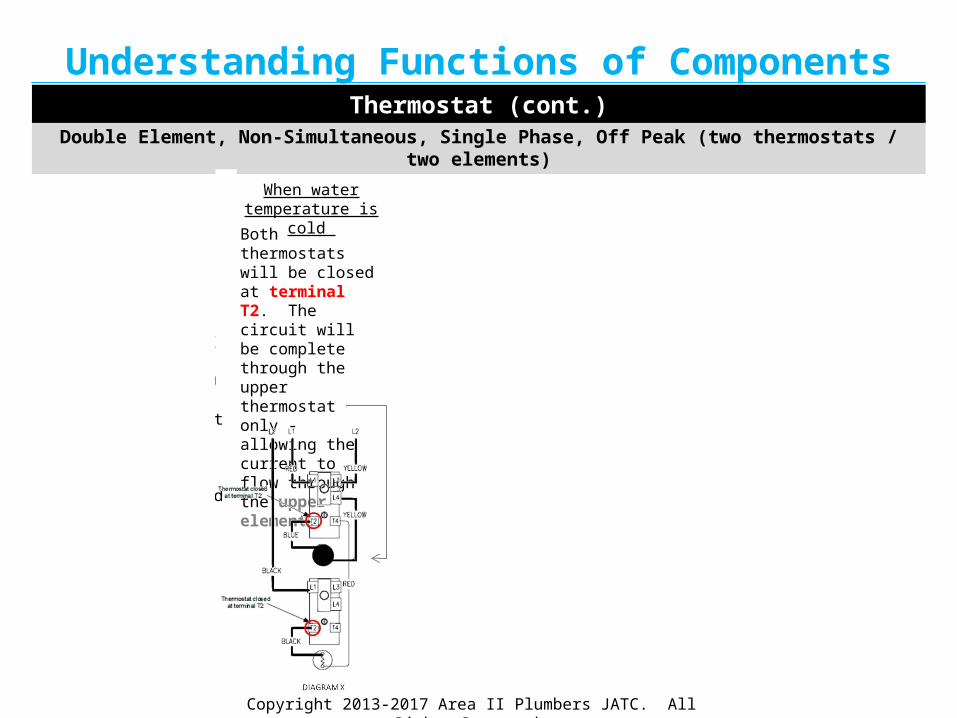
Double Element, Non-Simultaneous, Single Phase (two thermostats / two elements)
Electricity (line voltage) is applied across terminal L1 and terminal L3 of the thermostat. The ECO (Energy Cut Off) is closed, so there is voltage at terminal L4 and to one side of the upper and lower elements.

Copyright 2013-2017 Area II Plumbers JATC. All Rights Reserved.
Understanding Functions of Components
Electricity (line voltage) is applied across terminal L1 and terminal L3 of the thermostat. The ECO (Energy Cut Off) is closed, so there is voltage at terminal L4 and to one side of the upper and lower elements.
Both thermostats will be closed at terminal T2 and terminal 2. The circuit will be complete through the upper thermostat only-allowing the current to flow through the upper element.
When water temperature is cold
Thermostat (cont.)
Double Element, Non-Simultaneous, Single Phase (two thermostats / two elements)
The upper thermostat will be satisfied, terminal T2 will be open, there will be no current to the upper element, and terminal T4 will be closed—allowing flow through the lower thermostat and the lower element.
When water in the tophalf is optimally heated

Copyright 2013-2017 Area II Plumbers JATC. All Rights Reserved.
Understanding Functions of Components
Electricity (line voltage) is applied across terminal L1 and terminal L3 of the thermostat. The ECO (Energy Cut Off) is closed, so there is voltage at terminal L4 and to one side of the upper and lower elements.
Both thermostats will be closed at terminal T2 and terminal 2. The circuit will be complete through the upper thermostat only-allowing the current to flow through the upper element.
The upper thermostat will be satisfied, terminal T2 will be open, there will be no current to the upper element, and terminal T4 will be closed—allowing flow through the lower thermostat and the lower element.
When water temperature is cold
When water in the tophalf is optimally heated
Thermostat (cont.)
Double Element, Non-Simultaneous, Single Phase (two thermostats / two elements)
Because the lower thermostat is satisfied, terminal 2 will open and the lower element will no longer heat – placing the system in stand-by mode.
When water in the bottom half is optimally heated

Copyright 2013-2017 Area II Plumbers JATC. All Rights Reserved.
Understanding Functions of Components
Electricity (line voltage) is applied across terminal L1 and terminal L3 of the thermostat. The ECO (Energy Cut Off) is closed, so there is voltage at terminal L4 and to one side of the upper and lower elements.
Both thermostats will be closed at terminal T2 and terminal 2. The circuit will be complete through the upper thermostat only-allowing the current to flow through the upper element.
The upper thermostat will be satisfied, terminal T2 will be open, there will be no current to the upper element, and terminal T4 will be closed—allowing flow through the lower thermostat and the lower element.
When water temperature is cold
When water in the tophalf is optimally heated
Because the lower thermostat is satisfied, terminal 2 will open and the lower element will no longer heat – placing the system in stand-by mode.
When water in the bottom half is optimally heated
Thermostat (cont.)
Double Element, Non-Simultaneous, Single Phase (two thermostats / two elements)
When the tank is cold, and in times of high demand, the upper thermostat will engage before the lower thermostat has reached it’s optimal temperature. Terminal T4 will open and terminal T2 will close. As a result, only the upper element will heat.
On and Off Cycling
Copyright 2013-2017 Area II Plumbers JATC. All Rights Reserved.
Thermostat Components
Double Element, Simultaneous, Single Phase, 4 Wire Service
(two thermostats / two elements)
Copyright 2013-2017 Area II Plumbers JATC. All Rights Reserved.
Understanding Functions of ComponentsThermostat (cont.)

Copyright 2013-2017 Area II Plumbers JATC. All Rights Reserved.
Understanding Functions of Components
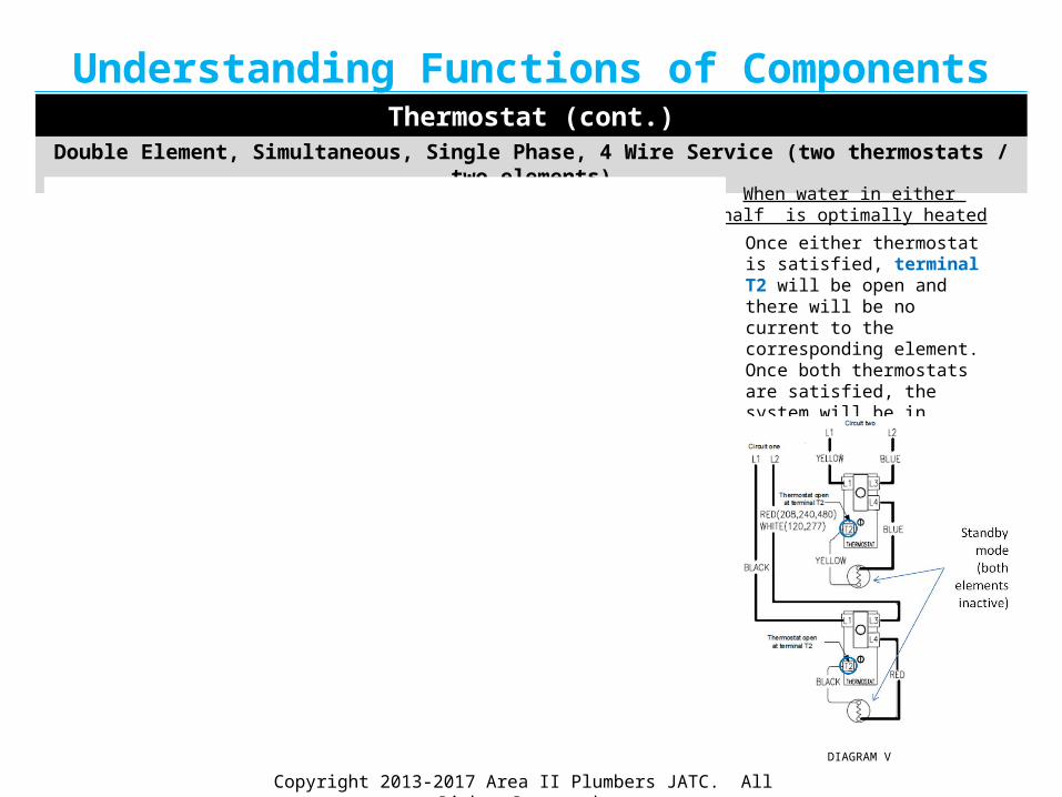
Double Element, Simultaneous, Single Phase, 4 Wire Service (two thermostats / two elements)
Thermostat (cont.)

Copyright 2013-2017 Area II Plumbers JATC. All Rights Reserved.
Understanding Functions of Components
Double Element, Simultaneous, Single Phase, 4 Wire Service (two thermostats / two elements)
Thermostat (cont.)
Electricity (line voltage) for circuit one is applied across terminal L1 and terminal L3 of the lower thermostat. Voltage for circuit two is applied across terminal L1 and terminal L3 of the upper thermostat. The ECO (Energy Cut Off) in both thermostats is closed, so there is voltage at terminal L4 of each thermostat and to one side of the upper and lower elements.
DIAGRAM T

Copyright 2013-2017 Area II Plumbers JATC. All Rights Reserved.
Understanding Functions of Components
Double Element, Simultaneous, Single Phase, 4 Wire Service (two thermostats / two elements)
Electricity (line voltage) for circuit one is applied across terminal L1 and terminal L3 of the lower thermostat. Voltage for circuit two is applied across terminal L1 and terminal L3 of the upper thermostat. The ECO (Energy Cut Off) in both thermostats is closed, so there is voltage at terminal L4 of each thermostat and to one side of the upper and lower elements.
Thermostat (cont.)
DIAGRAM T
Both thermostats will be closed at terminal T2. The circuit will be complete through both thermostats-allowing the current to flow through both elements.
When water temperature is cold
DIAGRAM U
DIAGRAM U
Copyright 2013-2017 Area II Plumbers JATC. All Rights Reserved.
Understanding Functions of Components
Double Element, Simultaneous, Single Phase, 4 Wire Service (two thermostats / two elements)
Electricity (line voltage) for circuit one is applied across terminal L1 and terminal L3 of the lower thermostat. Voltage for circuit two is applied across terminal L1 and terminal L3 of the upper thermostat. The ECO (Energy Cut Off) in both thermostats is closed, so there is voltage at terminal L4 of each thermostat and to one side of the upper and lower elements.
Both thermostats will be closed at terminal T2. The circuit will be complete through both thermostats-allowing the current to flow through both elements.
Thermostat (cont.)
When water temperature is cold
DIAGRAM T DIAGRAM U
Once either thermostat is satisfied, terminal T2 will be open and there will be no current to the corresponding element. Once both thermostats are satisfied, the system will be in stand-by mode. Thermostats will operate independent of one another.
When water in either half is optimally heated
DIAGRAM V

Copyright 2013-2017 Area II Plumbers JATC. All Rights Reserved.
Thermostat Components
Double Element, Non-Simultaneous, Single Phase, Off Peak
(two thermostats / two elements)

Copyright 2013-2017 Area II Plumbers JATC. All Rights Reserved.
Understanding Functions of ComponentsThermostat (cont.)

Copyright 2013-2017 Area II Plumbers JATC. All Rights Reserved.
Understanding Functions of Components
Double Element, Non-Simultaneous, Single Phase, Off Peak (two thermostats / two elements)
Thermostat (cont.)

Copyright 2013-2017 Area II Plumbers JATC. All Rights Reserved.
Understanding Functions of Components
Double Element, Non-Simultaneous, Single Phase, Off Peak (two thermostats / two elements)
Thermostat (cont.)
Electricity (line voltage) is applied across terminal L1 and terminal L3 of the upper thermostat. Line voltage from off peak meter is supplied to terminal L1 of lower thermostat. The ECO (Energy Cut Off) in the upper thermostat is closed, so there is voltage at terminal L4 of the upper thermostat and to one side of the upper element.
Both thermostats will be closed at terminal T2. The circuit will be complete through the upper thermostat only - allowing the current to flow through the upper element.
When water temperature is cold

Copyright 2013-2017 Area II Plumbers JATC. All Rights Reserved.
Understanding Functions of Components
Double Element, Non-Simultaneous, Single Phase, Off Peak (two thermostats / two elements)
Thermostat (cont.)
Electricity (line voltage) is applied across terminal L1 and terminal L3 of the upper thermostat. Line voltage from off peak meter is supplied to terminal L1 of lower thermostat. The ECO (Energy Cut Off) in the upper thermostat is closed, so there is voltage at terminal L4 of the upper thermostat and to one side of the upper element.
Both thermostats will be closed at terminal T2. The circuit will be complete through the upper thermostat only-allowing the current to flow through the upper element.
When water temperature is cold
The upper thermostat will be satisfied, terminal T2 will be open, there will be no current to the upper element, and terminal T4 will be closed—allowing flow through one side of the lower thermostat. With the circuit through the lower thermostat and off peak meter now complete, there will be flow through the lower element.
When water in the tophalf is optimally heated

Copyright 2013-2017 Area II Plumbers JATC. All Rights Reserved.
Understanding Functions of Components
Double Element, Non-Simultaneous, Single Phase, Off Peak (two thermostats / two elements)
Thermostat (cont.)
Electricity (line voltage) is applied across terminal L1 and terminal L3 of the upper thermostat. Line voltage from off peak meter is supplied to terminal L1 of lower thermostat. The ECO (Energy Cut Off) in the upper thermostat is closed, so there is voltage at terminal L4 of the upper thermostat and to one side of the upper element.
Both thermostats will be closed at terminal T2. The circuit will be complete through the upper thermostat only -allowing the current to flow through the upper element.
The upper thermostat will be satisfied, terminal T2 will be open, there will be no current to the upper element, and terminal T4 will be closed—allowing flow through one side of the lower thermostat. With the circuit through the lower thermostat and off peak meter now complete, there will be flow through the lower element.
When water temperature is cold
When water in the tophalf is optimally heated
Because the lower thermostat is satisfied, terminal T2 will open and the lower element will no longer heat – placing the system in stand-by mode.
When water in the bottom half is optimally heated
The off peak meter will interrupt power to terminal L1 of the lower thermostat. Only the top thermostat / element combination is allowed to operate. Note: the local utility will determine high demand times.
Peak Power Demands

Copyright 2013-2017 Area II Plumbers JATC. All Rights Reserved.
Electrical Components

Copyright 2013-2017 Area II Plumbers JATC. All Rights Reserved.
Understanding Functions of Components
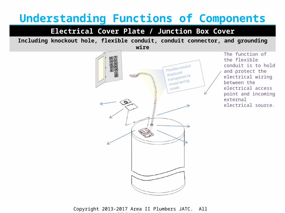
Including knockout hole, flexible conduit, conduit connector, and grounding wire
Electrical Cover Plate / Junction Box Cover
The electrical cover plate serves as both the cover and as the ground.
Copyright 2013-2017 Area II Plumbers JATC. All Rights Reserved.
Understanding Functions of Components
Including knockout hole, flexible conduit, conduit connector, and grounding wire
Electrical Cover Plate / Junction Box Cover
The function of the flexible conduit is to hold and protect the electrical wiring between the electrical access point and incoming external electrical source.

Copyright 2013-2017 Area II Plumbers JATC. All Rights Reserved.
Understanding Functions of Components
Including knockout hole, flexible conduit, conduit connector, and grounding wire
Electrical Cover Plate / Junction Box Cover
The conduit connector is thread into the knockout hole. The conduit will be fitted into the conduit connector.

Copyright 2013-2017 Area II Plumbers JATC. All Rights Reserved.
Understanding Functions of Components
Including knockout hole, flexible conduit, conduit connector, and grounding wire
Electrical Cover Plate / Junction Box Cover
If there is no established hole (i.e., on the electrical cover plate), there should be a knockout hole available near the cover plate. Once the hole cover has been removed, the wires will eventually feed into this hole to provide the electrical source to the water heater.

Copyright 2013-2017 Area II Plumbers JATC. All Rights Reserved.
Remaining Components
Copyright 2013-2017 Area II Plumbers JATC. All Rights Reserved.
Understanding Functions of Remaining ComponentsHeating Elements

Copyright 2013-2017 Area II Plumbers JATC. All Rights Reserved.
Understanding Functions of Remaining ComponentsHeating Elements
This is a screw in heating element for a residential water heater.

Copyright 2013-2017 Area II Plumbers JATC. All Rights Reserved.
Understanding Functions of Remaining ComponentsHeating Elements
This is a screw in heating element for a residential water heater.
Electricity is supplied to the heating element when the thermostat registers a pre-determined drop in water temperature.
Electricity is supplied to the heating element when the thermostat registers a pre-determined drop in water temperature. The element(s) then heat the water until it reaches a pre-determined temperature. The thermostat will then prevent the electricity from reaching the element—until the water has become too cool again—when the cycle will repeat.

Copyright 2013-2017 Area II Plumbers JATC. All Rights Reserved.
Understanding Functions of Remaining ComponentsHeating Elements
This is a screw in heating element for a residential water heater.
Electricity is supplied to the heating element when the thermostat registers a pre-determined drop in water temperature.
The screw in heating element is
A simple U-shape element. The ad-vantage of this element is cost-effectiveness.
Electricity is supplied to the heating element when the thermostat registers a pre-determined drop in water temperature. The element(s) then heat the water until it reaches a pre-determined temperature. The thermostat will then prevent the electricity from reaching the element—until the water has become too cool again—when the cycle will repeat.
connected to the water heaterwith a large thread and nut. The
Element pictured (lower left), is

Copyright 2013-2017 Area II Plumbers JATC. All Rights Reserved.
Understanding Functions of Remaining ComponentsHeating Elements
Another heating elements design is the folded back version. Pictured below (side right). The advantage of this design is its ability to prevent mineral buildup. The cost is a disadvantage when compared to the more widely used, simple, U-shape element.
This is a screw in heating element for a residential water heater.
Electricity is supplied to the heating element when the thermostat registers a pre-determined drop in water temperature.
The screw in heating element is
A simple U-shape element. The ad-vantage of this element is cost-effectiveness.
Electricity is supplied to the heating element when the thermostat registers a pre-determined drop in water temperature. The element(s) then heat the water until it reaches a pre-determined temperature. The thermostat will then prevent the electricity from reaching the element—until the water has become too cool again—when the cycle will repeat.
connected to the water heaterwith a large thread and nut. The
Element pictured (lower left), is

Copyright 2013-2017 Area II Plumbers JATC. All Rights Reserved.
Understanding Functions of Remaining ComponentsHot Water Outlet Components
Copyright 2013-2017 Area II Plumbers JATC. All Rights Reserved.
Understanding Functions of Remaining ComponentsHot Water Outlet Components
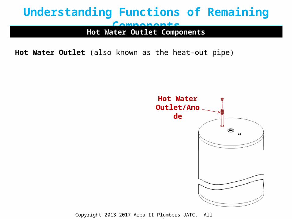
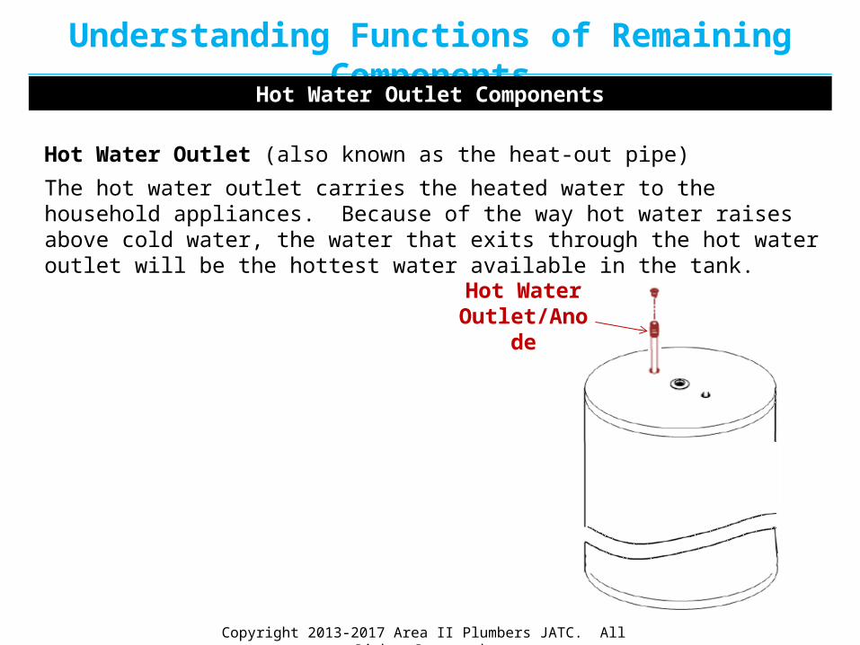
Hot Water Outlet (also known as the heat-out pipe)
Hot Water Outlet/Anode
Copyright 2013-2017 Area II Plumbers JATC. All Rights Reserved.
Understanding Functions of Remaining ComponentsHot Water Outlet Components
The hot water outlet carries the heated water to the household appliances. Because of the way hot water raises above cold water, the water that exits through the hot water outlet will be the hottest water available in the tank.
Hot Water Outlet (also known as the heat-out pipe)
Hot Water Outlet/Anode

Copyright 2013-2017 Area II Plumbers JATC. All Rights Reserved.
Understanding Functions of Remaining ComponentsHot Water Outlet Components
The hot water outlet carries the heated water to the household appliances. Because of the way hot water raises above cold water, the water that exits through the hot water outlet will be the hottest water available in the tank.
Hot Water Outlet (also known as the heat-out pipe)
Heat Trap InsertHot Water
Outlet/Anode
Heat Trap Insert
(Outlet)

Copyright 2013-2017 Area II Plumbers JATC. All Rights Reserved.
Understanding Functions of Remaining ComponentsHot Water Outlet Components
The hot water outlet carries the heated water to the household appliances. Because of the way hot water raises above cold water, the water that exits through the hot water outlet will be the hottest water available in the tank.
The heat trap insert prevents excessive heat loss through the outlet piping. A good heat trap insert would reduce standby heat loss up to 40% or more.
Hot Water Outlet (also known as the heat-out pipe)
Heat Trap InsertHot Water
Outlet/Anode
Heat Trap Insert
(Outlet)

Copyright 2013-2017 Area II Plumbers JATC. All Rights Reserved.
Understanding Functions of Remaining Components
The older version of heat trap inserts utilize a ball, which is prone to making noise. The newer versions are quieter.
Hot Water Outlet Components
The hot water outlet carries the heated water to the household appliances. Because of the way hot water raises above cold water, the water that exits through the hot water outlet will be the hottest water available in the tank.
The heat trap insert prevents excessive heat loss through the outlet piping. A good heat trap insert would reduce standby heat loss up to 40% or more.
Hot Water Outlet (also known as the heat-out pipe)
Heat Trap InsertHot Water
Outlet/Anode
Heat Trap Insert
(Outlet)
Copyright 2013-2017 Area II Plumbers JATC. All Rights Reserved.
Understanding Functions of Remaining ComponentsCold Water Inlet (Dip Tube) Components

Copyright 2013-2017 Area II Plumbers JATC. All Rights Reserved.
Understanding Functions of Remaining ComponentsCold Water Inlet (Dip Tube) Components
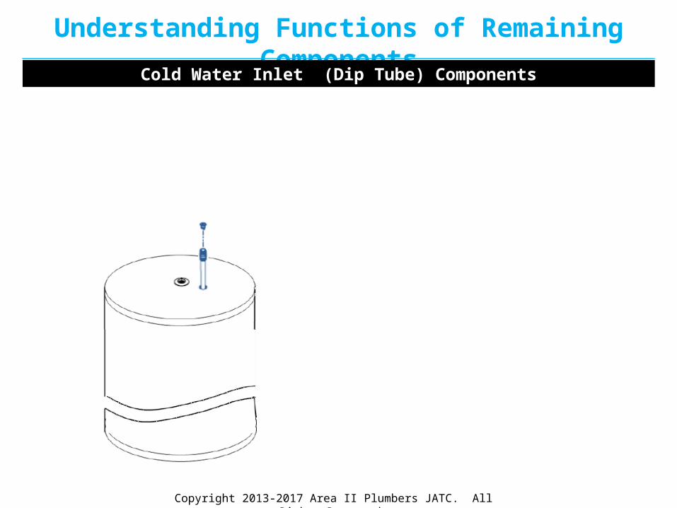
Cold Water Inlet (also known as the Dip Tube)
Cold Water Inlet Dip
Tube

Copyright 2013-2017 Area II Plumbers JATC. All Rights Reserved.
Understanding Functions of Remaining ComponentsCold Water Inlet (Dip Tube) Components
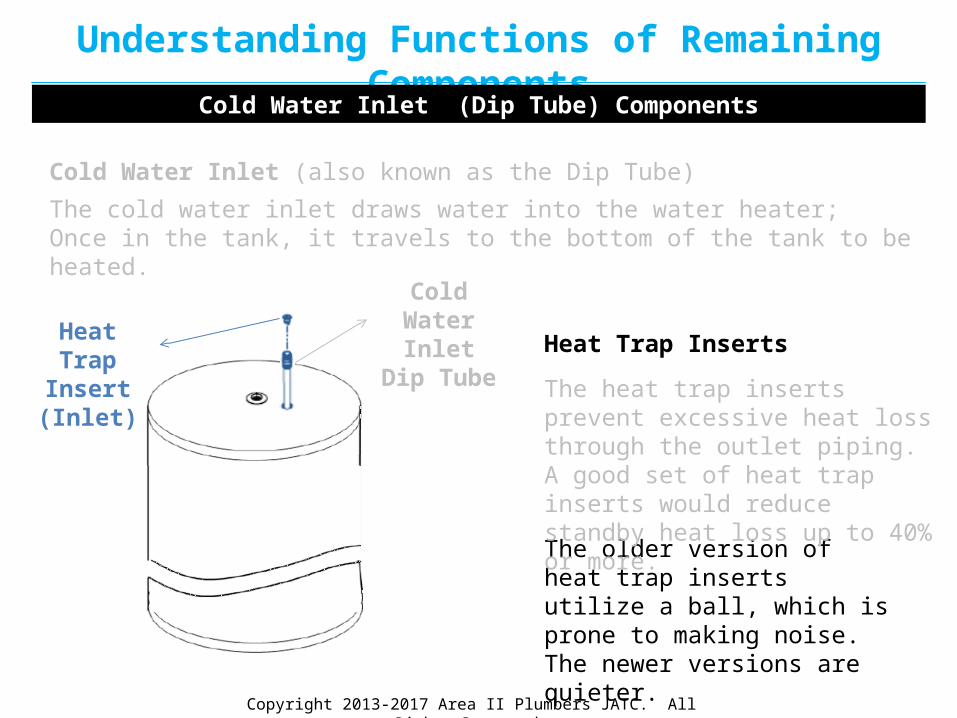
The cold water inlet draws water into the water heater; Once in the tank, it travels to the bottom of the tank to be heated.
Cold Water Inlet Dip
Tube
Cold Water Inlet (also known as the Dip Tube)

Copyright 2013-2017 Area II Plumbers JATC. All Rights Reserved.
Understanding Functions of Remaining ComponentsCold Water Inlet (Dip Tube) Components
Heat Trap Insert (Inlet)
Cold Water Inlet Dip
Tube
The cold water inlet draws water into the water heater; Once in the tank, it travels to the bottom of the tank to be heated.
Cold Water Inlet (also known as the Dip Tube)
Heat Trap Inserts

Copyright 2013-2017 Area II Plumbers JATC. All Rights Reserved.
Understanding Functions of Remaining ComponentsCold Water Inlet (Dip Tube) Components
Heat Trap Insert (Inlet)
Cold Water Inlet Dip
Tube
The cold water inlet draws water into the water heater; Once in the tank, it travels to the bottom of the tank to be heated.
Cold Water Inlet (also known as the Dip Tube)
The heat trap inserts prevent excessive heat loss through the outlet piping. A good set of heat trap inserts would reduce standby heat loss up to 40% or more.
Heat Trap Inserts
Copyright 2013-2017 Area II Plumbers JATC. All Rights Reserved.
Understanding Functions of Remaining ComponentsCold Water Inlet (Dip Tube) Components
Heat Trap Insert (Inlet)
Cold Water Inlet Dip
Tube
The cold water inlet draws water into the water heater; Once in the tank, it travels to the bottom of the tank to be heated.
Cold Water Inlet (also known as the Dip Tube)
The older version of heat trap inserts utilize a ball, which is prone to making noise. The newer versions are quieter.
The heat trap inserts prevent excessive heat loss through the outlet piping. A good set of heat trap inserts would reduce standby heat loss up to 40% or more.
Heat Trap Inserts

Copyright 2013-2017 Area II Plumbers JATC. All Rights Reserved.
Understanding Functions of Remaining ComponentsSacrificial Anode

Copyright 2013-2017 Area II Plumbers JATC. All Rights Reserved.
Understanding Functions of Remaining Components
Sacrificial Anode
The sacrificial anode rod draws to itself the harmful conductivity caused by oxygen, magnesium, fluoride, chlorine and suspended particles within the tank. In essence, it sacrifices itself by drawing this conductivity and allowing itself to be the focus of corrosion before the tank becomes deteriorated.
Sacrificial Anode
Not all water heaters have a sacrificial anode rod. Once the anode rod becomes corroded, it can cause a bad odor. The odor has been described as similar to rotten eggs.
However, this odor can also be caused by having an anode made of the wrong type of material. Sometimes, switching from one type (magnesium, zinc aluminum) to another can solve the problem.

Copyright 2013-2017 Area II Plumbers JATC. All Rights Reserved.
Understanding Functions of Remaining Components
T&P Relief Valve
Alternative Placement for the T&P Relief Valve
Temperature & Pressure Relief Valve

Copyright 2013-2017 Area II Plumbers JATC. All Rights Reserved.
Understanding Functions of Remaining Components
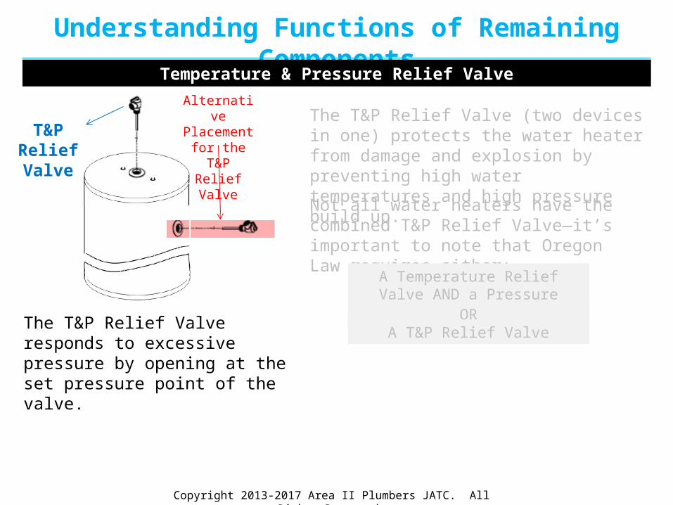
The T&P Relief Valve (two devices in one) protects the water heater from damage and explosion by preventing high water temperatures and high pressure build up.
T&P Relief Valve
Alternative Placement for the T&P Relief Valve
Temperature & Pressure Relief Valve

Copyright 2013-2017 Area II Plumbers JATC. All Rights Reserved.
Understanding Functions of Remaining Components
The T&P Relief Valve (two devices in one) protects the water heater from damage and explosion by preventing high water temperatures and high pressure build up.
T&P Relief Valve
Alternative Placement for the T&P Relief Valve
Temperature & Pressure Relief Valve
Not all water heaters have the combined T&P Relief Valve—it’s important to note that Oregon Law requires either:
A Temperature Relief Valve AND a Pressure Relief Valve
ORA T&P Relief Valve
Copyright 2013-2017 Area II Plumbers JATC. All Rights Reserved.
Understanding Functions of Remaining Components
The T&P Relief Valve (two devices in one) protects the water heater from damage and explosion by preventing high water temperatures and high pressure build up.
T&P Relief Valve
Alternative Placement for the T&P Relief Valve
Temperature & Pressure Relief Valve
Not all water heaters have the combined T&P Relief Valve—it’s important to note that Oregon Law requires either:
A Temperature Relief Valve AND a Pressure Relief Valve
ORA T&P Relief ValveThe T&P Relief Valve responds to
excessive pressure by opening at the set pressure point of the valve.

Copyright 2013-2017 Area II Plumbers JATC. All Rights Reserved.
Understanding Functions of Remaining Components
T&P Relief Valve
Alternative Placement for the T&P Relief Valve
Temperature & Pressure Relief Valve
The T&P Relief Valve responds to excessive pressure by opening at the set pressure point of the valve.
When it senses a build up of pressure, it opens to relieve the thermal expansion and returns the pressure back to normal.
The T&P Relief Valve (two devices in one) protects the water heater from damage and explosion by preventing high water temperatures and high pressure build up.
Not all water heaters have the combined T&P Relief Valve—it’s important to note that Oregon Law requires either:
A Temperature Relief Valve AND a Pressure Relief Valve
ORA T&P Relief Valve

Copyright 2013-2017 Area II Plumbers JATC. All Rights Reserved.
Understanding Functions of Remaining Components
The T&P Relief Valve (two devices in one) protects the water heater from damage and explosion by preventing high water temperatures and high pressure build up.
T&P Relief Valve
Alternative Placement for the T&P Relief Valve
Temperature & Pressure Relief Valve
Not all water heaters have the combined T&P Relief Valve—it’s important to note that Oregon Law requires either:
A Temperature Relief Valve AND a Pressure Relief Valve
ORA T&P Relief ValveThe T&P Relief Valve responds to
excessive pressure by opening at the set pressure point of the valve.
When it senses a build up of pressure, it opens to relieve the thermal expansion and returns the pressure back to normal.
When the temperature of the water reaches 210 degrees, the T&P Relief Valve discharges the overheated water, allowing the cooler water to enter the tank and bring temperatures back to normal.

Copyright 2013-2017 Area II Plumbers JATC. All Rights Reserved.
Understanding Functions of Remaining Components
Overflow Pipe
The overflow pipe, connected to the temperature / pressure relief valve, directs leaking water away from the tank and to the floor.
Diagram K1
Overflow Pipe
Overflow Pipe

Copyright 2013-2017 Area II Plumbers JATC. All Rights Reserved.
Understanding Functions of Remaining ComponentsShut-Off Valve (Water Supply Valve)

Copyright 2013-2017 Area II Plumbers JATC. All Rights Reserved.
Understanding Functions of Remaining Components
Whether the cold water shut-off valve, otherwise known as a water supply valve, is the gate or ball style—its function is to stop the flow of water into the tank. The ball valve is the
more widely used of the two.
Shut-OffBall
Valve
Shut-Off Valve (Water Supply Valve)
Shut-OffGate
Valve

Copyright 2013-2017 Area II Plumbers JATC. All Rights Reserved.
Understanding Functions of Remaining ComponentsDrain Valve
Copyright 2013-2017 Area II Plumbers JATC. All Rights Reserved.
Understanding Functions of Remaining ComponentsDrain Valve
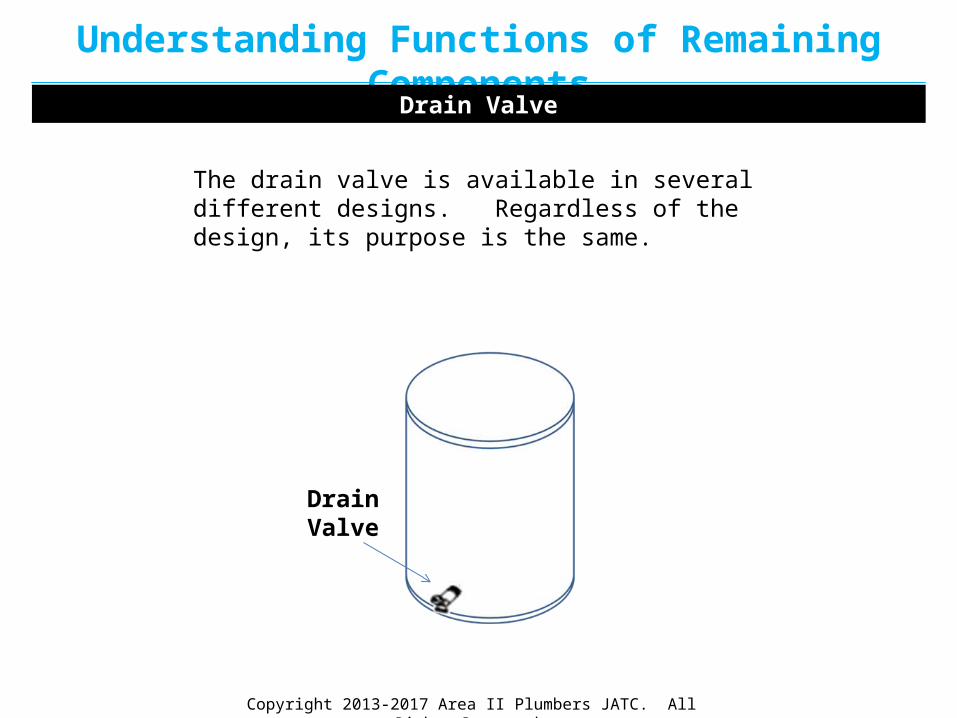
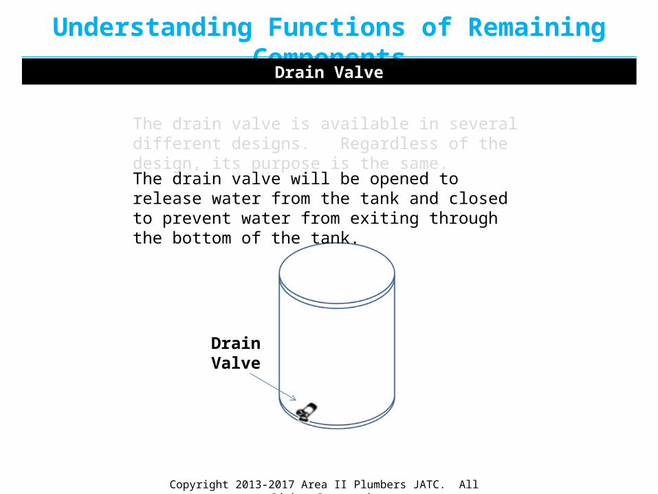
Drain Valve
The drain valve is available in several different designs. Regardless of the design, its purpose is the same.
Copyright 2013-2017 Area II Plumbers JATC. All Rights Reserved.
Understanding Functions of Remaining ComponentsDrain Valve
Drain Valve
The drain valve is available in several different designs. Regardless of the design, its purpose is the same.
The drain valve will be opened to release water from the tank and closed to prevent water from exiting through the bottom of the tank.

Copyright 2013-2017 Area II Plumbers JATC. All Rights Reserved.
Understanding Functions of Remaining ComponentsEarthquake Ties

Copyright 2013-2017 Area II Plumbers JATC. All Rights Reserved.
Understanding Functions of Remaining ComponentsEarthquake Ties
In seismic design categories C, D, E, and F, water heaters shall be anchored or strapped to resist horizontal displacement due to earthquake motion.
Return to Installing the Residential Hot Water Heater

Copyright 2013-2017 Area II Plumbers JATC. All Rights Reserved.
Understanding Functions of Remaining ComponentsEarthquake Ties
In seismic design categories C, D, E, and F, water heaters shall be anchored or strapped to resist horizontal displacement due to earthquake motion.
Exception: Water heaters in residential structures in seismic design category C
are not required to be strapped or anchored to resist horizontal
displacement due to earthquake motion.
Return to Installing the Residential Hot Water Heater

Copyright 2013-2017 Area II Plumbers JATC. All Rights Reserved.
Understanding Functions of Remaining ComponentsEarthquake Ties
EarthquakeTies
In seismic design categories C, D, E, and F, water heaters shall be anchored or strapped to resist horizontal displacement due to earthquake motion.
Strapping shall be at points within the upper one-third (1/3) and lower one-third (1/3) of its vertical dimensions.
Exception: Water heaters in residential structures in seismic design category C
are not required to be strapped or anchored to resist horizontal
displacement due to earthquake motion.
Return to Installing the Residential Hot Water Heater

Copyright 2013-2017 Area II Plumbers JATC. All Rights Reserved.
Understanding Functions of Remaining ComponentsEarthquake Ties
EarthquakeTies
In seismic design categories C, D, E, and F, water heaters shall be anchored or strapped to resist horizontal displacement due to earthquake motion.
At the lower point, a distance of not less than four (4) inches (102 mm) shall be maintained above the controls with the strapping.
Strapping shall be at points within the upper one-third (1/3) and lower one-third (1/3) of its vertical dimensions.
Exception: Water heaters in residential structures in seismic design category C
are not required to be strapped or anchored to resist horizontal
displacement due to earthquake motion.
Return to Installing the Residential Hot Water Heater