copper twin-axial cable
TRANSCRIPT
802.3 NGOATH Study Group1
50 Gb/s Ethernet over a Single Laneand Next Generation 100 Gb/s and200 Gb/s Ethernet Study Groups
Considerations for Cable Assembly, Test Fixture and Channel Specifications
Chris DiMinicoMC Communications/PHY-SI LLC/[email protected]
802.3 NGOATH Study Group2
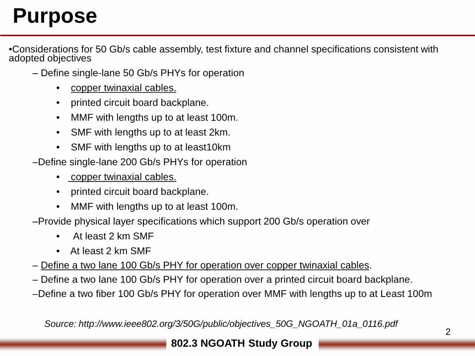
Purpose•Considerations for 50 Gb/s cable assembly, test fixture and channel specifications consistent with adopted objectives
‒ Define single-lane 50 Gb/s PHYs for operation• copper twinaxial cables.• printed circuit board backplane.• MMF with lengths up to at least 100m. • SMF with lengths up to at least 2km.• SMF with lengths up to at least10km
‒Define single-lane 200 Gb/s PHYs for operation• copper twinaxial cables.• printed circuit board backplane.• MMF with lengths up to at least 100m.
‒Provide physical layer specifications which support 200 Gb/s operation over• At least 2 km SMF• At least 2 km SMF
– Define a two lane 100 Gb/s PHY for operation over copper twinaxial cables.– Define a two lane 100 Gb/s PHY for operation over a printed circuit board backplane.–Define a two fiber 100 Gb/s PHY for operation over MMF with lengths up to at Least 100m
Source: http://www.ieee802.org/3/50G/public/objectives_50G_NGOATH_01a_0116.pdf
802.3 NGOATH Study Group3
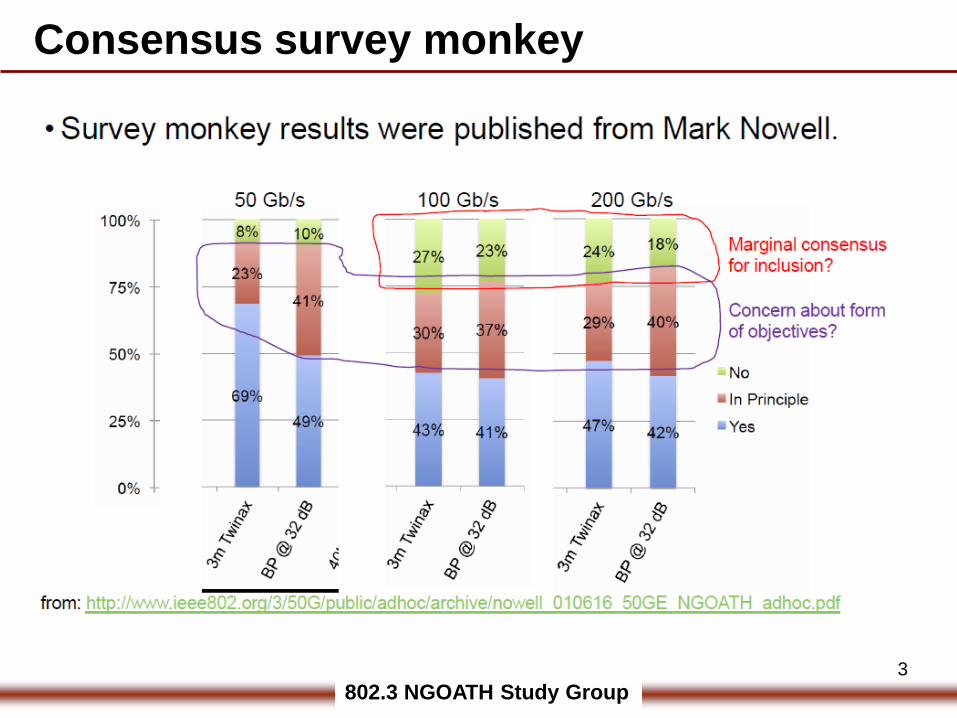
Consensus survey monkey
802.3 NGOATH Study Group4
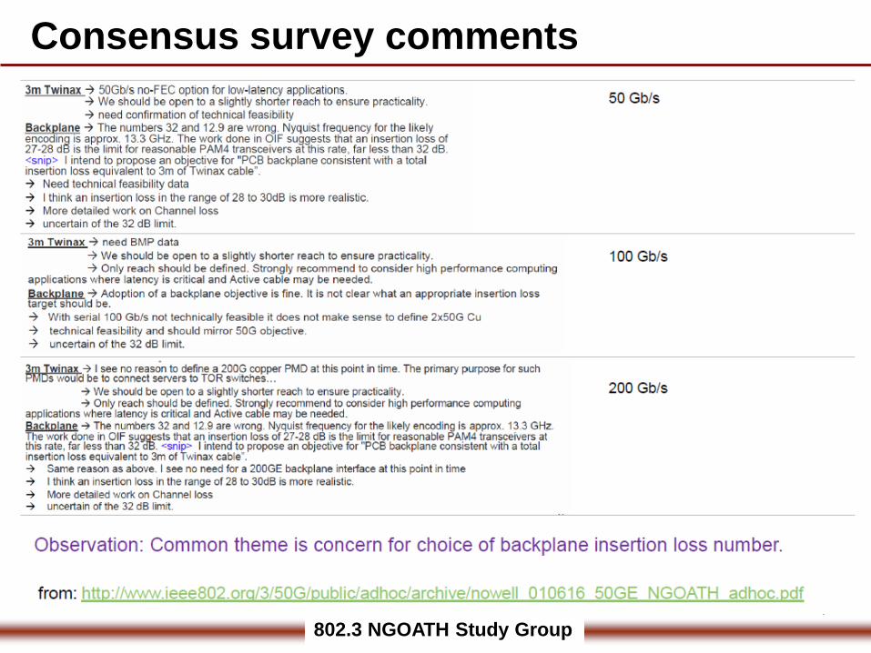
Consensus survey comments

802.3 NGOATH Study Group5
•Considerations for 50 Gb/s cable assembly, test fixture and channel specifications consistent with adopted objectives
‒ Define single-lane 50 Gb/s PHYs for operation• copper twinaxial cables.
–Define a two lane 100 Gb/s PHY for operation over copper twinaxial cables.‒Define single-lane 200 Gb/s PHYs for operation
• copper twinaxial cables.
•802.3by Adopted and approved Objective‒ Define a single‐lane 25 Gb/s PHY for operation over links consistent with copper twin axial cables, with lengths up to at least 3m
•Considerations for 50 Gb/s, 100 Gb/s, 200 Gb/s cable assembly, test fixture and channel specifications consistent with adopted objectives
‒ Define single-lane 50 Gb/s PHYs for operation over links consistent with copper twin axial cables with lengths up to at least 3 m. ‒Define two-lane 100 Gb/s PHYs for operation over links consistent with copper twin axial cables with lengths up to at least 3 m. –Define four-lane 200 Gb/s PHYs for operation over links consistent with copper twin axial cables with lengths up to at least 3 m.
Copper twinaxial cables objectives
802.3 NGOATH Study Group6
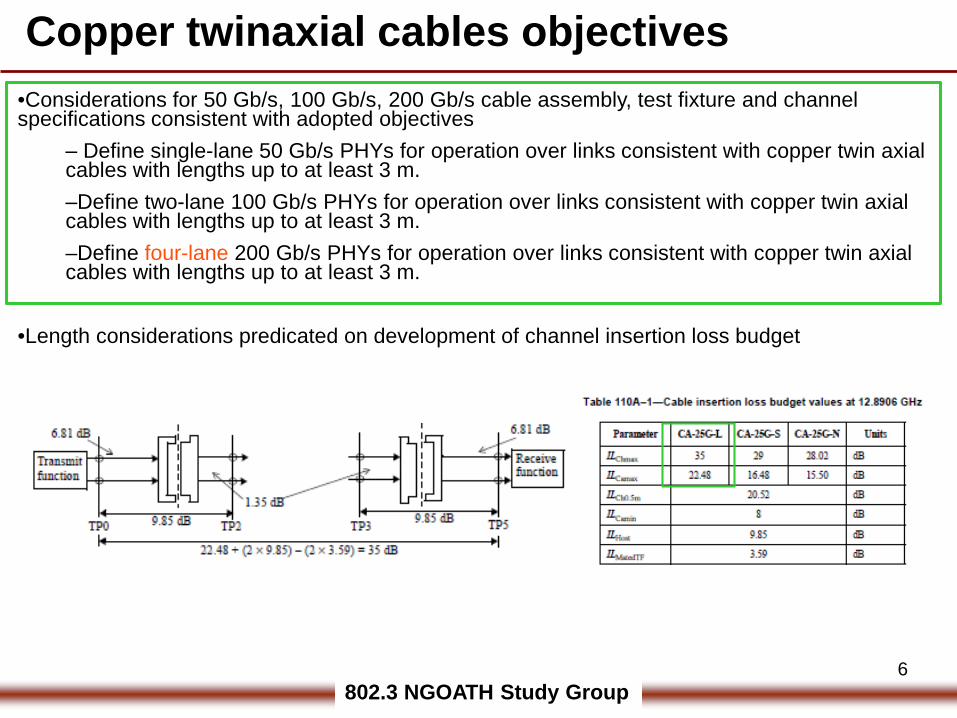
•Considerations for 50 Gb/s, 100 Gb/s, 200 Gb/s cable assembly, test fixture and channel specifications consistent with adopted objectives
‒ Define single-lane 50 Gb/s PHYs for operation over links consistent with copper twin axial cables with lengths up to at least 3 m. ‒Define two-lane 100 Gb/s PHYs for operation over links consistent with copper twin axial cables with lengths up to at least 3 m. –Define four-lane 200 Gb/s PHYs for operation over links consistent with copper twin axial cables with lengths up to at least 3 m.
•Length considerations predicated on development of channel insertion loss budget
Copper twinaxial cables objectives
802.3 NGOATH Study Group7
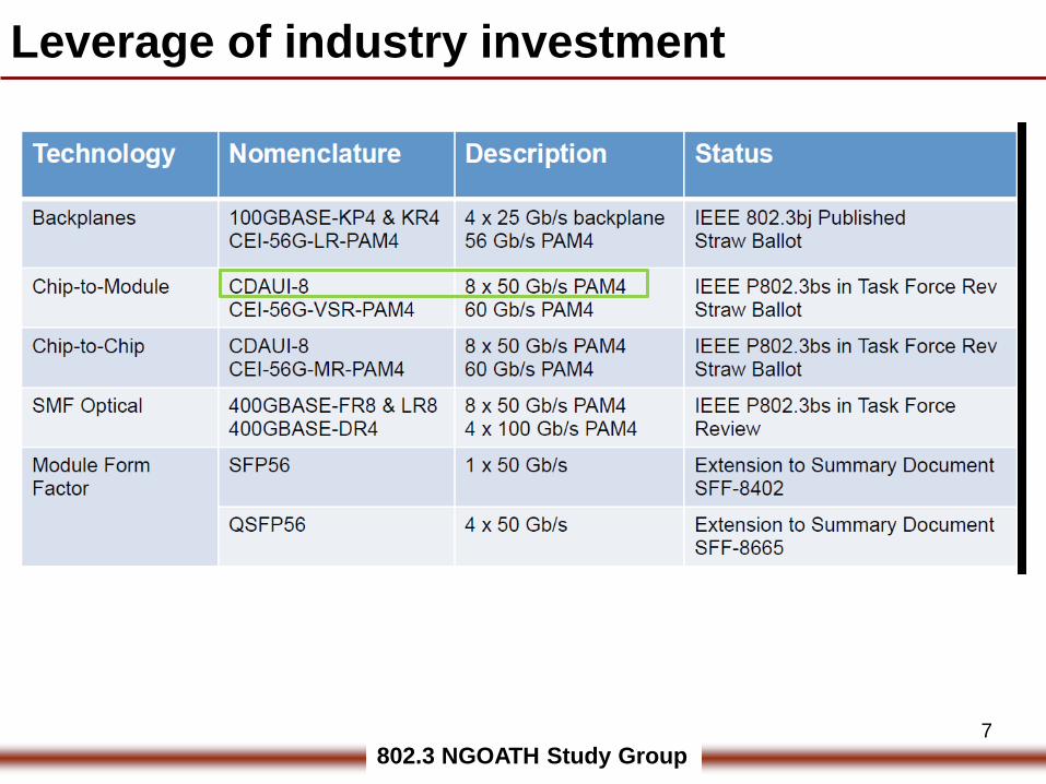
Leverage of industry investment
802.3 NGOATH Study Group8
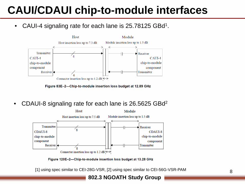
CAUI/CDAUI chip-to-module interfaces• CAUI-4 signaling rate for each lane is 25.78125 GBd1.
• CDAUI-8 signaling rate for each lane is 26.5625 GBd2
[1] using spec similar to CEI-28G-VSR, [2] using spec similar to CEI-56G-VSR-PAM
802.3 NGOATH Study Group9
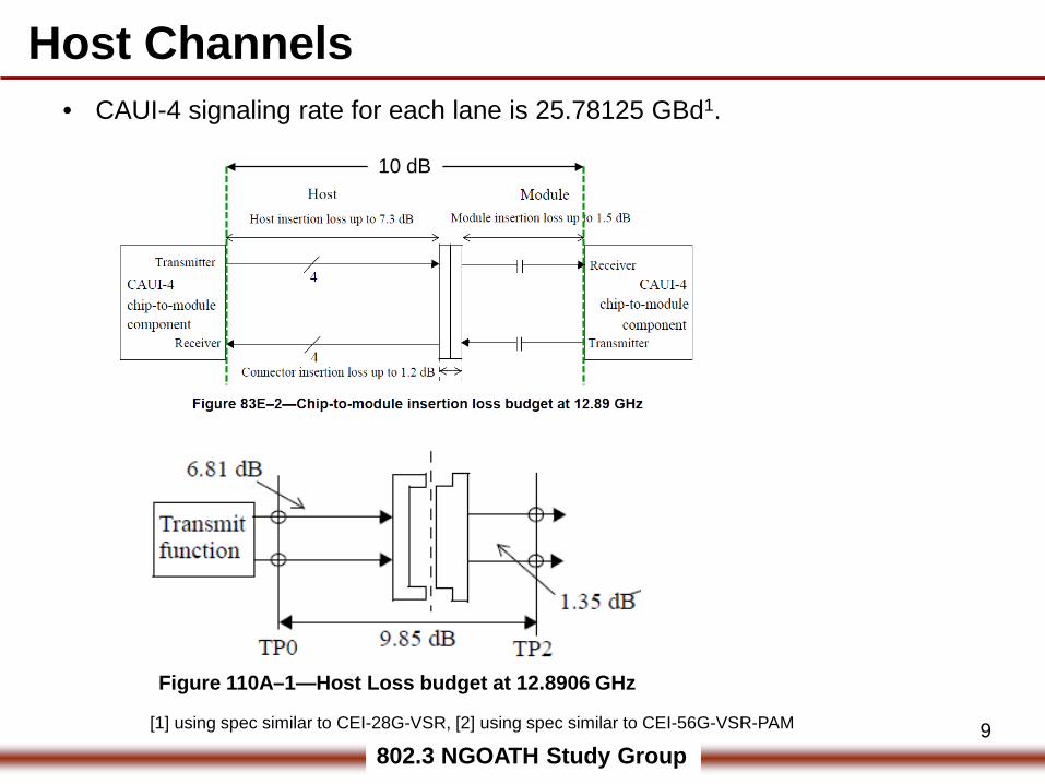
Host Channels• CAUI-4 signaling rate for each lane is 25.78125 GBd1.
[1] using spec similar to CEI-28G-VSR, [2] using spec similar to CEI-56G-VSR-PAM
Figure 110A–1—Host Loss budget at 12.8906 GHz
10 dB
802.3 NGOATH Study Group10
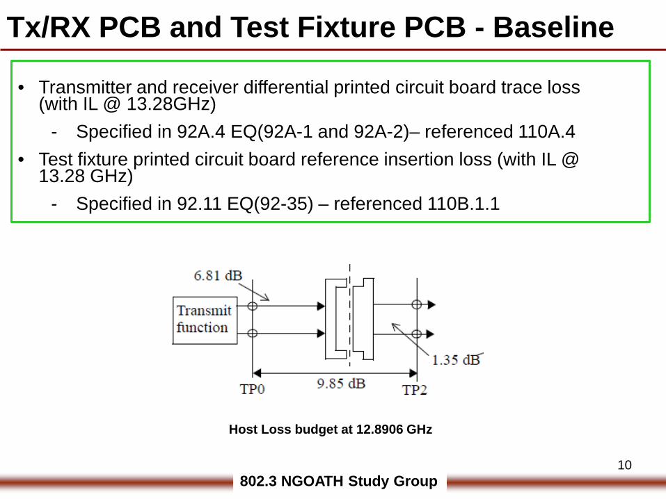
Tx/RX PCB and Test Fixture PCB - Baseline
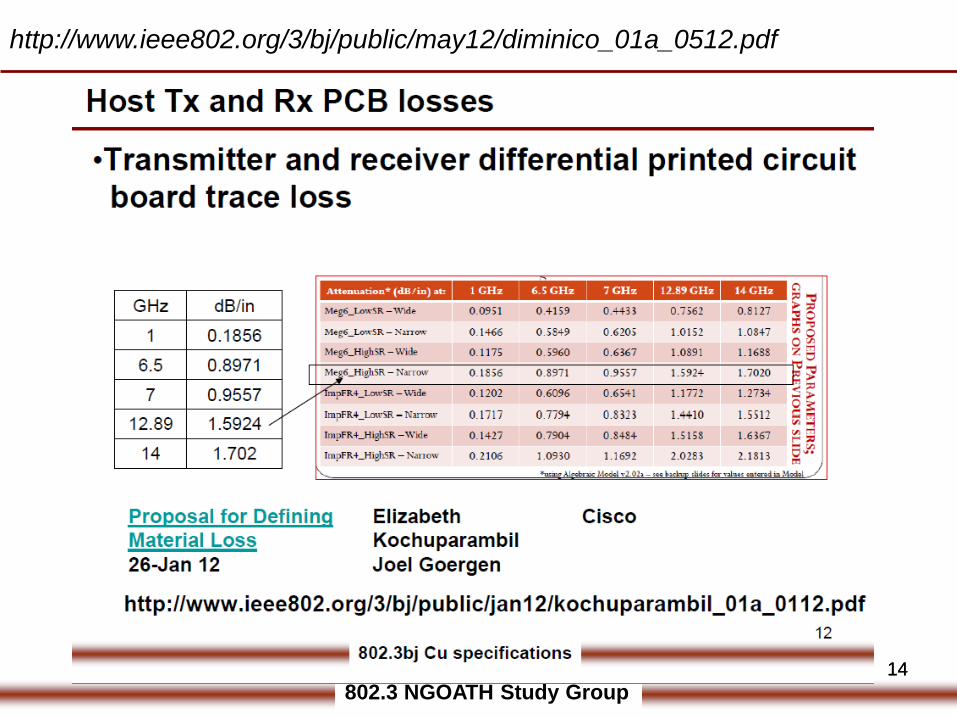
• Transmitter and receiver differential printed circuit board trace loss (with IL @ 13.28GHz)
- Specified in 92A.4 EQ(92A-1 and 92A-2)– referenced 110A.4• Test fixture printed circuit board reference insertion loss (with IL @
13.28 GHz)- Specified in 92.11 EQ(92-35) – referenced 110B.1.1
Host Loss budget at 12.8906 GHz
802.3 NGOATH Study Group11
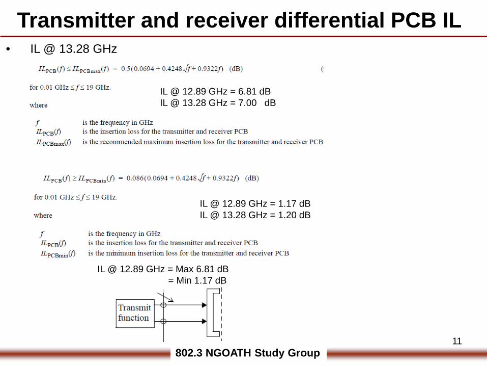
Transmitter and receiver differential PCB IL
IL @ 12.89 GHz = 6.81 dBIL @ 13.28 GHz = 7.00 dB
IL @ 12.89 GHz = 1.17 dBIL @ 13.28 GHz = 1.20 dB
• IL @ 13.28 GHz
IL @ 12.89 GHz = Max 6.81 dB= Min 1.17 dB
802.3 NGOATH Study Group
12
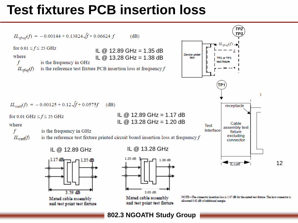
Test fixtures PCB insertion lossTP2TP3
IL @ 12.89 GHz
IL @ 12.89 GHz = 1.35 dBIL @ 13.28 GHz = 1.38 dB
IL @ 12.89 GHz = 1.17 dBIL @ 13.28 GHz = 1.20 dB
IL @ 13.28 GHz1.20 dB 1.38 dB
3.65 dB
802.3 NGOATH Study Group13
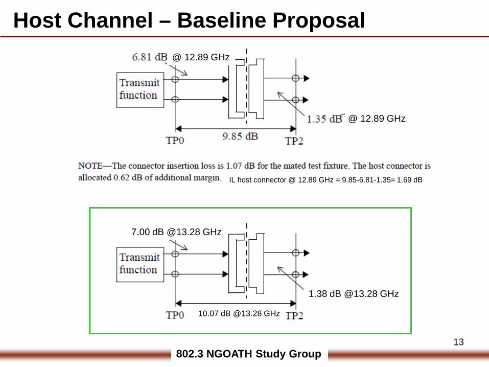
Host Channel – Baseline Proposal
@ 12.89 GHz
7.00 dB @13.28 GHz
1.38 dB @13.28 GHz
IL host connector @ 12.89 GHz = 9.85-6.81-1.35= 1.69 dB
@ 12.89 GHz
10.07 dB @13.28 GHz
802.3 NGOATH Study Group1414
http://www.ieee802.org/3/bj/public/may12/diminico_01a_0512.pdf
802.3 NGOATH Study Group
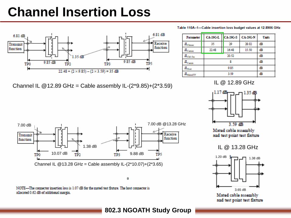
Channel Insertion Loss
7.00 dB
1.38 dB
Channel IL @13.28 GHz = Cable assembly IL-(2*10.07)+(2*3.65)
IL @ 13.28 GHz1.20 dB 1.38 dB
3.65 dB
IL @ 12.89 GHzChannel IL @12.89 GHz = Cable assembly IL-(2*9.85)+(2*3.59)
7.00 dB @13.28 GHz
10.07 dB 9.88 dB
802.3 NGOATH Study Group
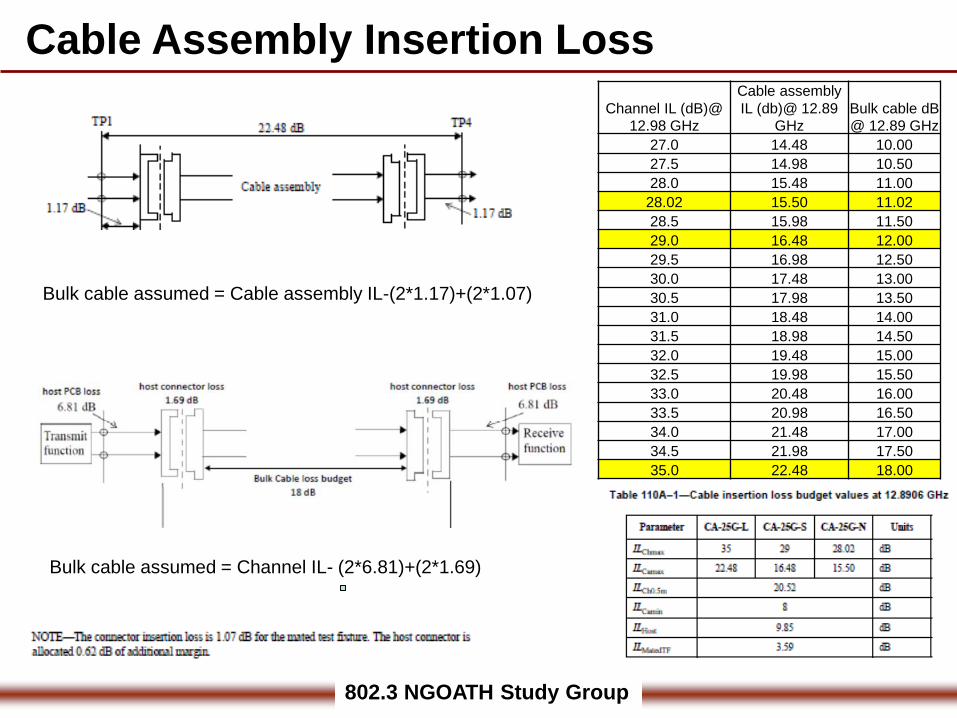
Cable Assembly Insertion Loss
Bulk cable assumed = Cable assembly IL-(2*1.17)+(2*1.07)
Bulk cable assumed = Channel IL- (2*6.81)+(2*1.69)
Channel IL (dB)@ 12.98 GHz
Cable assembly IL (db)@ 12.89
GHzBulk cable dB @ 12.89 GHz
27.0 14.48 10.0027.5 14.98 10.5028.0 15.48 11.00
28.02 15.50 11.0228.5 15.98 11.5029.0 16.48 12.0029.5 16.98 12.5030.0 17.48 13.0030.5 17.98 13.5031.0 18.48 14.0031.5 18.98 14.5032.0 19.48 15.0032.5 19.98 15.5033.0 20.48 16.0033.5 20.98 16.5034.0 21.48 17.0034.5 21.98 17.5035.0 22.48 18.00
802.3 NGOATH Study Group
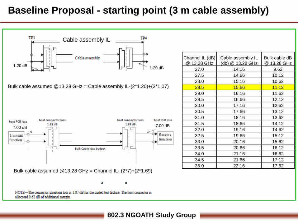
Baseline Proposal - starting point (3 m cable assembly)
Bulk cable assumed @13.28 GHz = Cable assembly IL-(2*1.20)+(2*1.07)
1.20 dB 1.20 dB
Cable assembly IL
Channel IL (dB) @ 13.28 GHz
Cable assembly IL (db) @ 13.28 GHz
Bulk cable dB @ 13.28 GHz
27.0 14.16 9.6227.5 14.66 10.1228.0 15.16 10.6228.5 15.66 11.1229.0 16.16 11.6229.5 16.66 12.1230.0 17.16 12.6230.5 17.66 13.1231.0 18.16 13.6231.5 18.66 14.1232.0 19.16 14.6232.5 19.66 15.1233.0 20.16 15.6233.5 20.66 16.1234.0 21.16 16.6234.5 21.66 17.1235.0 22.16 17.62
Bulk cable assumed @13.28 GHz = Channel IL- (2*7)+(2*1.69)
7.00 dB 7.00 dB
802.3 NGOATH Study Group18
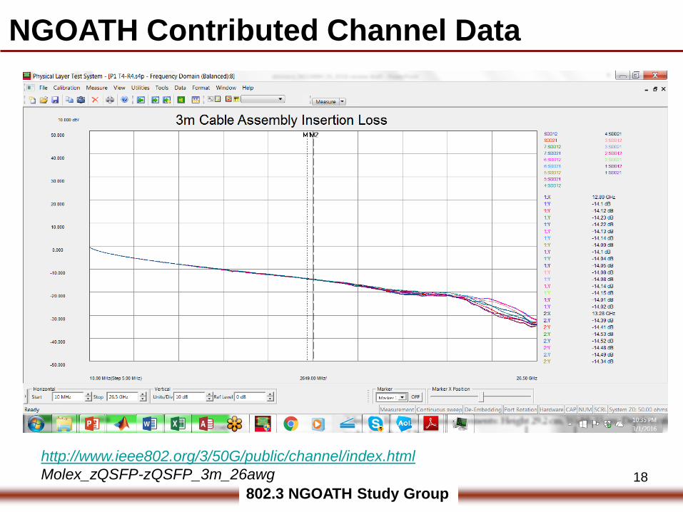
http://www.ieee802.org/3/50G/public/channel/index.htmlMolex_zQSFP-zQSFP_3m_26awg
NGOATH Contributed Channel Data
802.3 NGOATH Study Group19
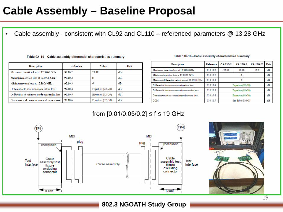
Cable Assembly – Baseline Proposal
• Cable assembly - consistent with CL92 and CL110 – referenced parameters @ 13.28 GHz
from [0.01/0.05/0.2] ≤ f ≤ 19 GHz
802.3 NGOATH Study Group20
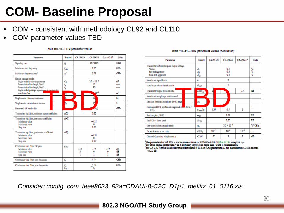
COM- Baseline Proposal• COM - consistent with methodology CL92 and CL110• COM parameter values TBD
TBD TBD
Consider: config_com_ieee8023_93a=CDAUI-8-C2C_D1p1_mellitz_01_0116.xls
802.3 NGOATH Study Group2121
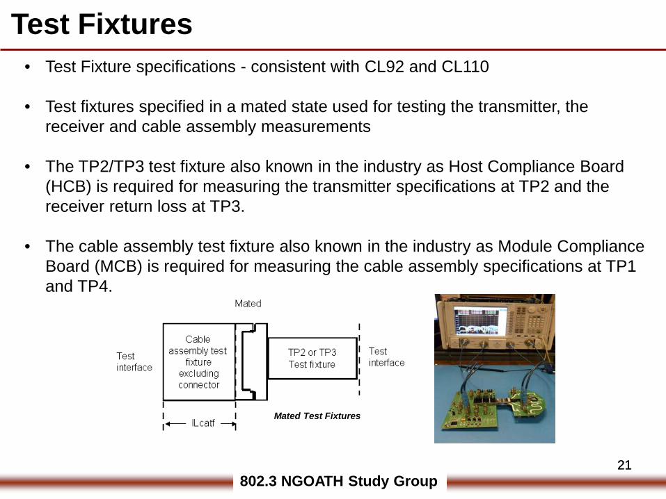
• Test Fixture specifications - consistent with CL92 and CL110
• Test fixtures specified in a mated state used for testing the transmitter, the receiver and cable assembly measurements
• The TP2/TP3 test fixture also known in the industry as Host Compliance Board (HCB) is required for measuring the transmitter specifications at TP2 and the receiver return loss at TP3.
• The cable assembly test fixture also known in the industry as Module Compliance Board (MCB) is required for measuring the cable assembly specifications at TP1 and TP4.
Mated Test Fixtures
Test Fixtures
802.3 NGOATH Study Group2222
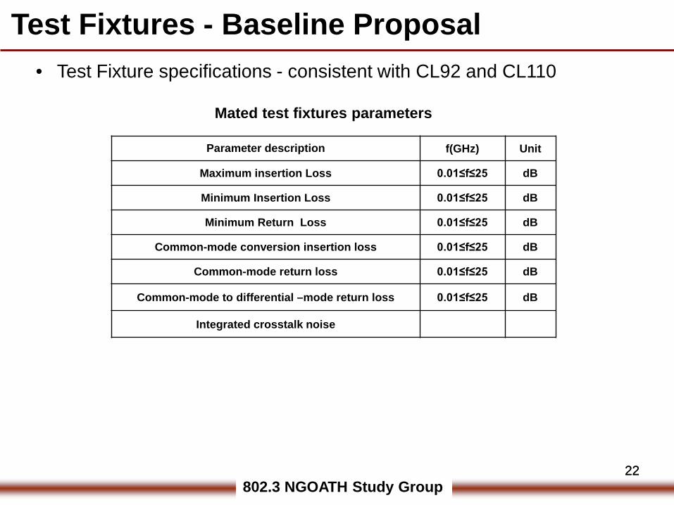
• Test Fixture specifications - consistent with CL92 and CL110
Test Fixtures - Baseline Proposal
Parameter description f(GHz) Unit
Maximum insertion Loss 0.01≤f≤25 dB
Minimum Insertion Loss 0.01≤f≤25 dB
Minimum Return Loss 0.01≤f≤25 dB
Common-mode conversion insertion loss 0.01≤f≤25 dB
Common-mode return loss 0.01≤f≤25 dB
Common-mode to differential –mode return loss 0.01≤f≤25 dB
Integrated crosstalk noise
Mated test fixtures parameters
802.3 NGOATH Study Group23
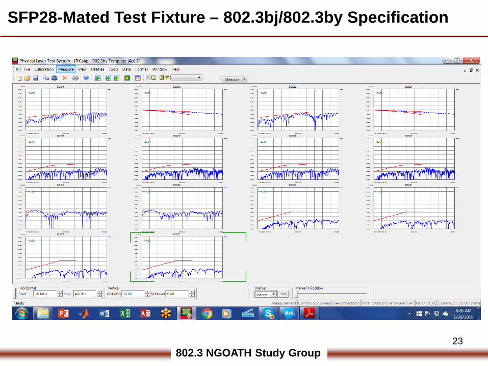
SFP28-Mated Test Fixture – 802.3bj/802.3by Specification
802.3 NGOATH Study Group24
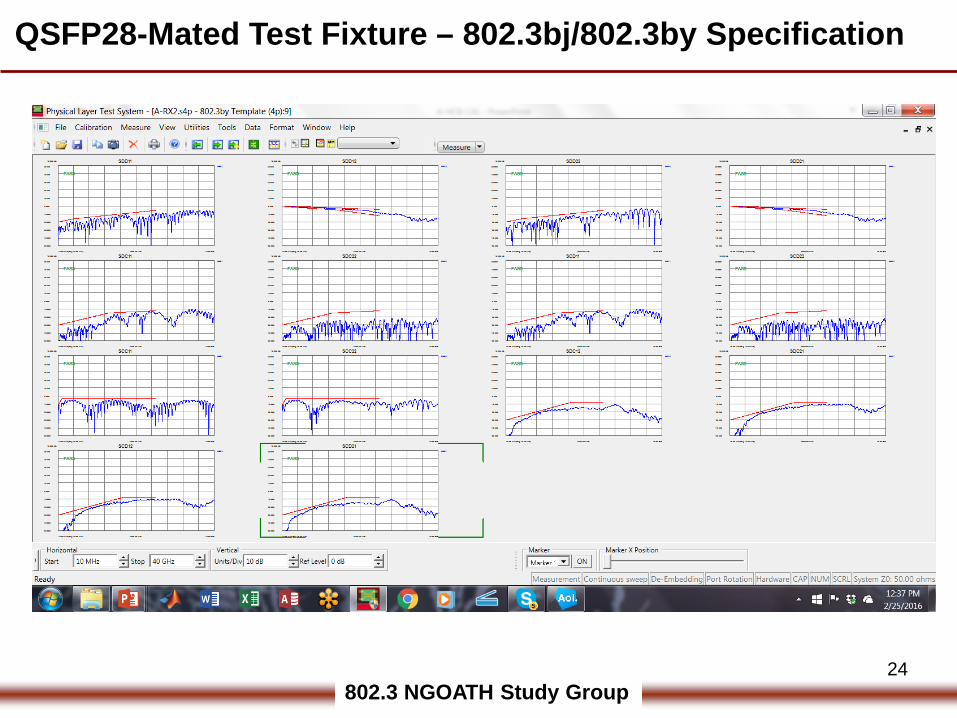
QSFP28-Mated Test Fixture – 802.3bj/802.3by Specification
802.3 NGOATH Study Group25
BACKUP
802.3 NGOATH Study Group26
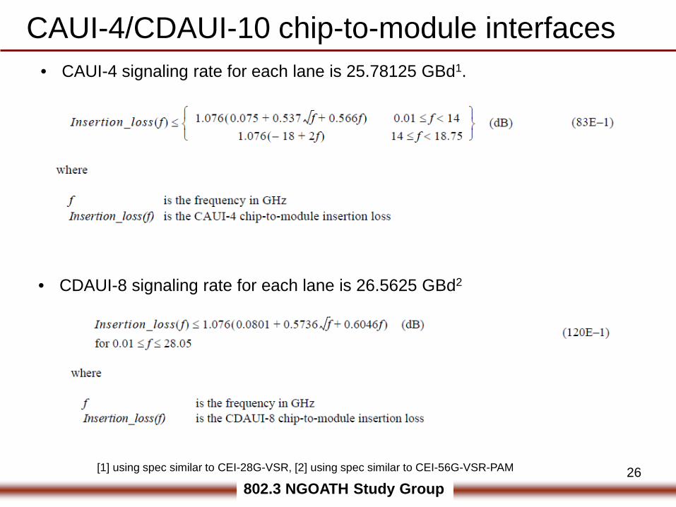
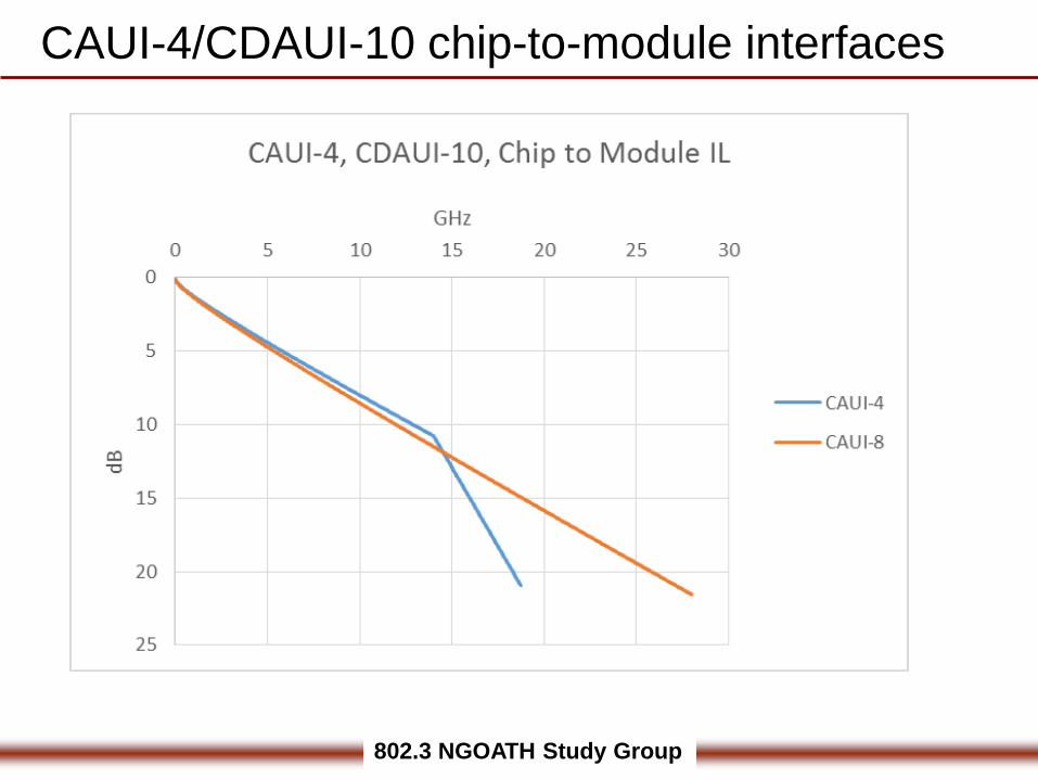
CAUI-4/CDAUI-10 chip-to-module interfaces• CAUI-4 signaling rate for each lane is 25.78125 GBd1.
• CDAUI-8 signaling rate for each lane is 26.5625 GBd2
[1] using spec similar to CEI-28G-VSR, [2] using spec similar to CEI-56G-VSR-PAM
802.3 NGOATH Study Group
CAUI-4/CDAUI-10 chip-to-module interfaces