coordinate systems, measured surveys for bim, total ... · • tekla structures • autodesk revit...
TRANSCRIPT

• Coordinate systems,
• measured surveys for BIM,
• total station for BIM,
• as-built surveys,
• setting-out
What is a BIM
What does a BIM do
Why use a BIM
BIM Software
BIM and the Surveyor
How do they relate to us in the Surveying and Spatial industry
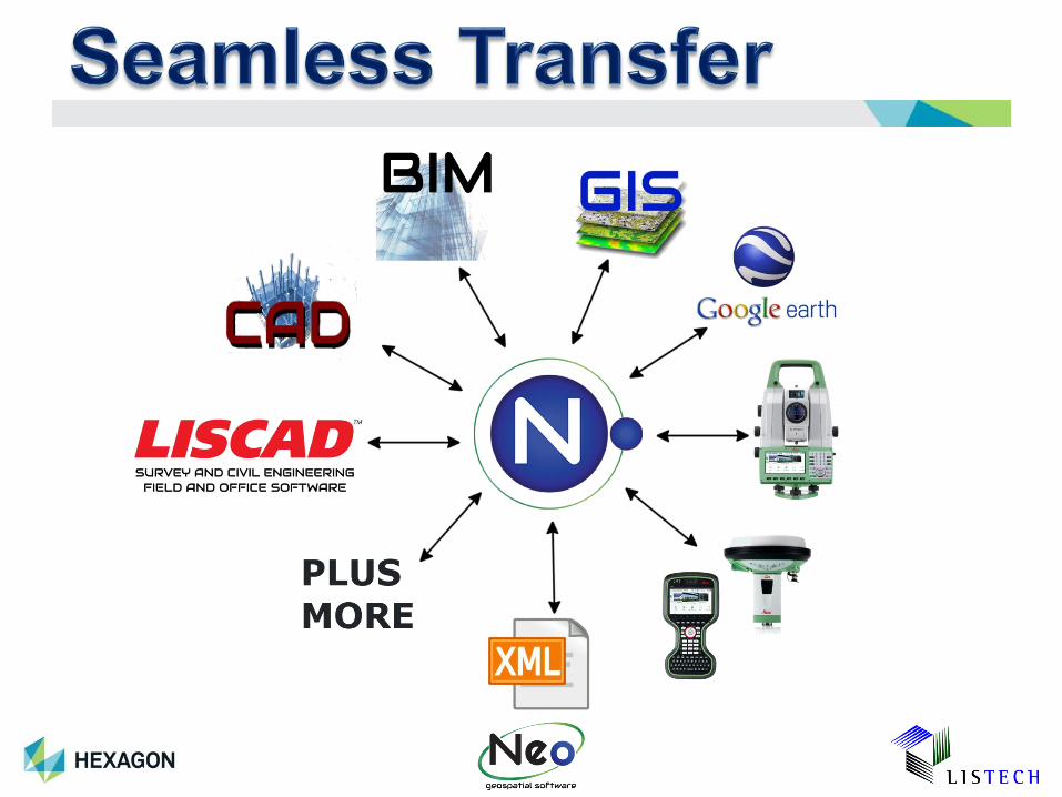
LISTECH Neo – The surveyors interface to BIM
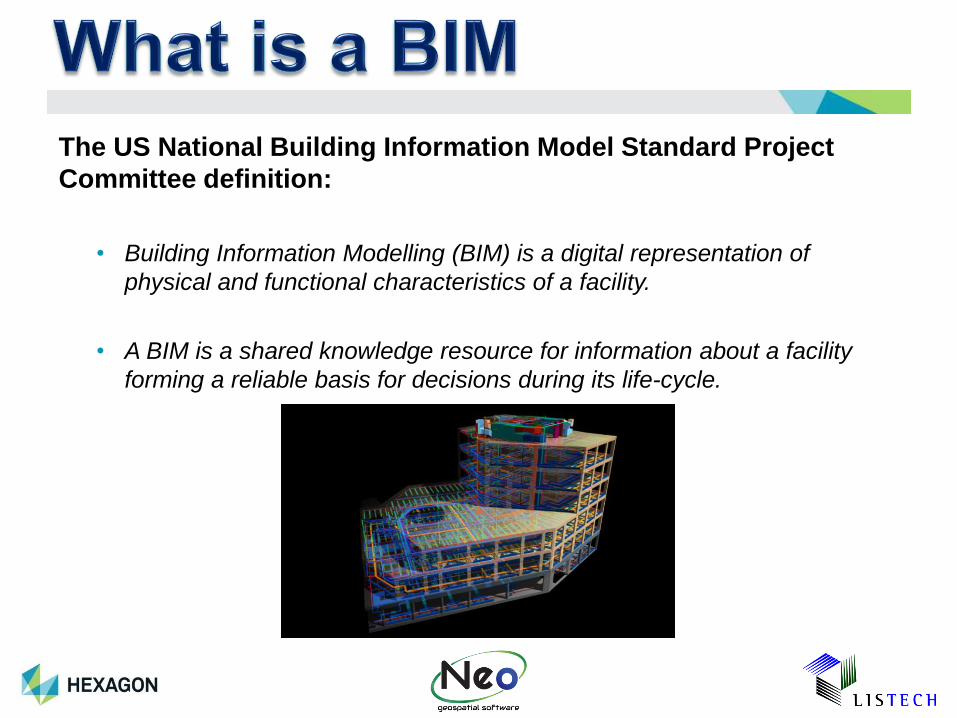
The US National Building Information Model Standard Project
Committee definition:
• Building Information Modelling (BIM) is a digital representation of
physical and functional characteristics of a facility.
• A BIM is a shared knowledge resource for information about a facility
forming a reliable basis for decisions during its life-cycle.
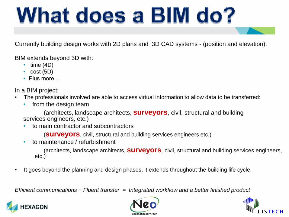
Currently building design works with 2D plans and 3D CAD systems - (position and elevation).
BIM extends beyond 3D with:• time (4D)
• cost (5D)
• Plus more…
In a BIM project:• The professionals involved are able to access virtual information to allow data to be transferred:
• from the design team
(architects, landscape architects, surveyors, civil, structural and building services engineers, etc.)
• to main contractor and subcontractors
(surveyors, civil, structural and building services engineers etc.)
• to maintenance / refurbishment
(architects, landscape architects, surveyors, civil, structural and building services engineers, etc.)
• It goes beyond the planning and design phases, it extends throughout the building life cycle.
Efficient communications + Fluent transfer = Integrated workflow and a better finished product
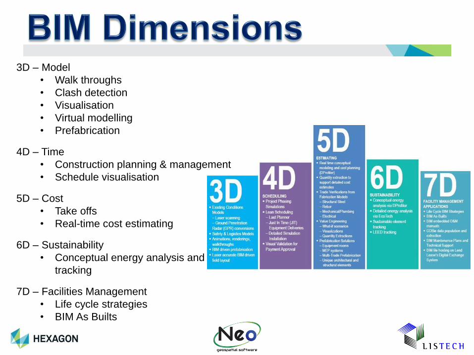
3D – Model
• Walk throughs
• Clash detection
• Visualisation
• Virtual modelling
• Prefabrication
4D – Time
• Construction planning & management
• Schedule visualisation
5D – Cost
• Take offs
• Real-time cost estimating
6D – Sustainability
• Conceptual energy analysis and
tracking
7D – Facilities Management
• Life cycle strategies
• BIM As Builts
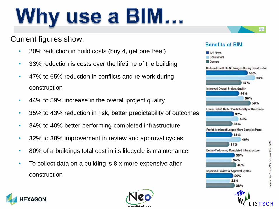
Current figures show:
• 20% reduction in build costs (buy 4, get one free!)
• 33% reduction is costs over the lifetime of the building
• 47% to 65% reduction in conflicts and re-work during
construction
• 44% to 59% increase in the overall project quality
• 35% to 43% reduction in risk, better predictability of outcomes
• 34% to 40% better performing completed infrastructure
• 32% to 38% improvement in review and approval cycles
• 80% of a buildings total cost in its lifecycle is maintenance
• To collect data on a building is 8 x more expensive after
construction

Software designed specifically for BIM include:
• Bentley AECOsim Building Designer
• ArchiCAD
• Tekla Structures
• Autodesk Revit
• VectorWorks
These packages have their proprietary data formats.
Non-proprietary or open BIM standards
• BIM is associated with Industry Foundation Classes (IFCs) and aecXML
• IFCs have been developed by buildingSMART (the former International Alliance for
Interoperability), as a neutral, non-proprietary or open standard for sharing BIM data
among different software applications.

Owner
Surveyor:
Existing conditions / Detail Survey
Property Manager
BIM Architect
Engineers
Surveyor:
Sets out Design for Builder/Contractors
Contractor
Builder
Surveyor:
Title Survey
Surveyor:
Performs As
Constructed
Survey
Issues that Surveyors will and do encounter with BIM.
• Coordinate Systems
• Measuring with Total Stations and GNSS
• Set out
• As constructed
• Creating Point Data
• Attributing
BIM’s and the “real world”.
BIM’s a system for the management of the construction of a “Building”
• Usually on a “local” coordinate datum
• No scale factors
BIM’s now being used for larger infrastructure projects – rail, road and
other such projects that are over a larger area.
• Need to work in the real world
• Datum’s and Projections
• Real world coordinates
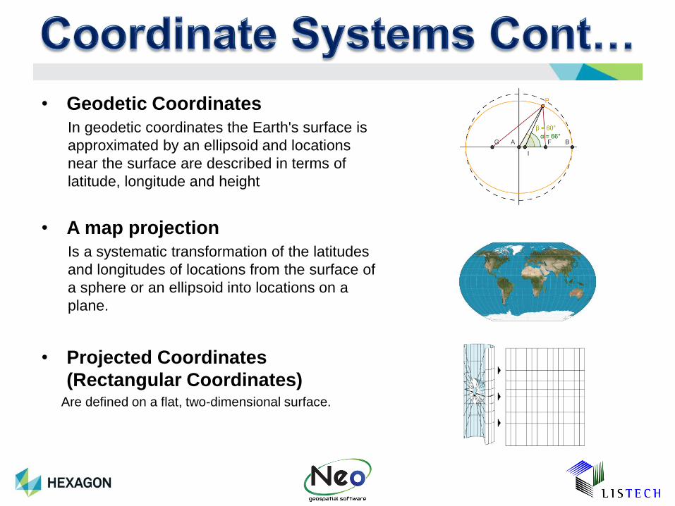
• Geodetic Coordinates
In geodetic coordinates the Earth's surface is
approximated by an ellipsoid and locations
near the surface are described in terms of
latitude, longitude and height
• A map projection
Is a systematic transformation of the latitudes
and longitudes of locations from the surface of
a sphere or an ellipsoid into locations on a
plane.
• Projected Coordinates
(Rectangular Coordinates)Are defined on a flat, two-dimensional surface.
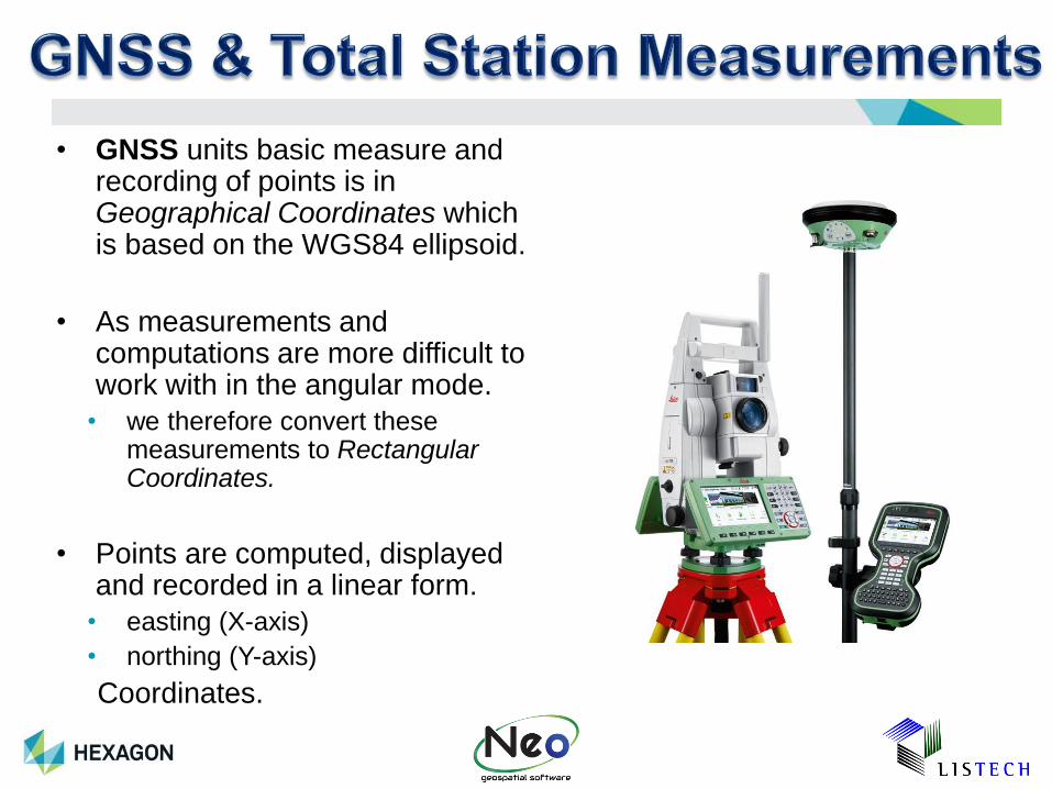
• GNSS units basic measure and recording of points is in Geographical Coordinates which is based on the WGS84 ellipsoid.
• As measurements and computations are more difficult to work with in the angular mode.
• we therefore convert these measurements to Rectangular Coordinates.
• Points are computed, displayed and recorded in a linear form.
• easting (X-axis)
• northing (Y-axis)
Coordinates.
Issues that Surveyors deal with daily….
What is…
• a ground distance?
• an ellipsoid distance?
• a grid distance?
• a local distance?
• a plane bearing?
• a Grid bearing?
• a local bearing?
• Sea Level Correction?
• Projection Point & Line Scale Factors?
• Combined Scale Factor?
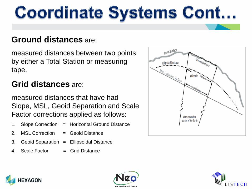
Ground distances are:
measured distances between two points
by either a Total Station or measuring
tape.
Grid distances are:
measured distances that have had
Slope, MSL, Geoid Separation and Scale
Factor corrections applied as follows:
1. Slope Correction = Horizontal Ground Distance
2. MSL Correction = Geoid Distance
3. Geoid Separation = Ellipsoidal Distance
4. Scale Factor = Grid Distance
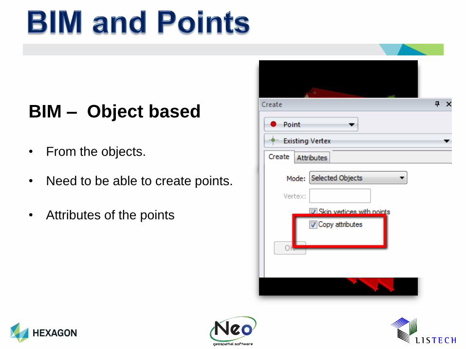
BIM – Object based
• From the objects.
• Need to be able to create points.
• Attributes of the points
The Surveyors interface to BIM
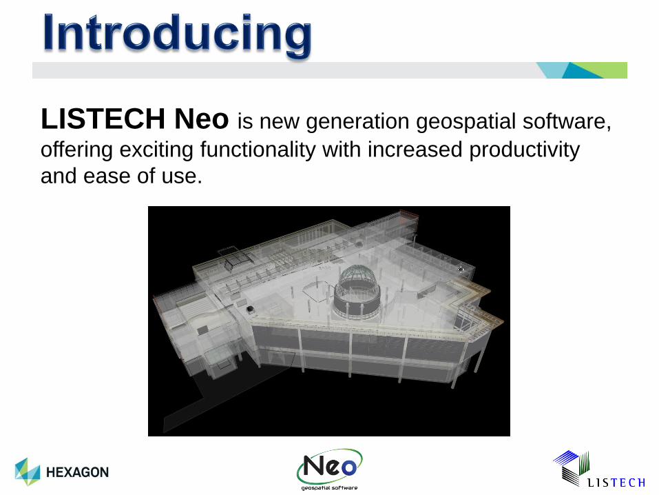
LISTECH Neo is new generation geospatial software,
offering exciting functionality with increased productivity
and ease of use.
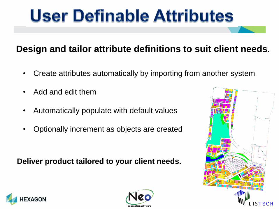
Design and tailor attribute definitions to suit client needs.
• Points and point symbols
• Lines (made up of straight, arc and spline segments) and line styles
• Polygons and polygon hatching
• Annotations (text) with TrueType fonts
• Integrated 3D topological database
• Fully self contained database (embedded file system)
• Create attributes automatically by importing from another system
• Add and edit them
• Automatically populate with default values
• Optionally increment as objects are created
Deliver product tailored to your client needs.
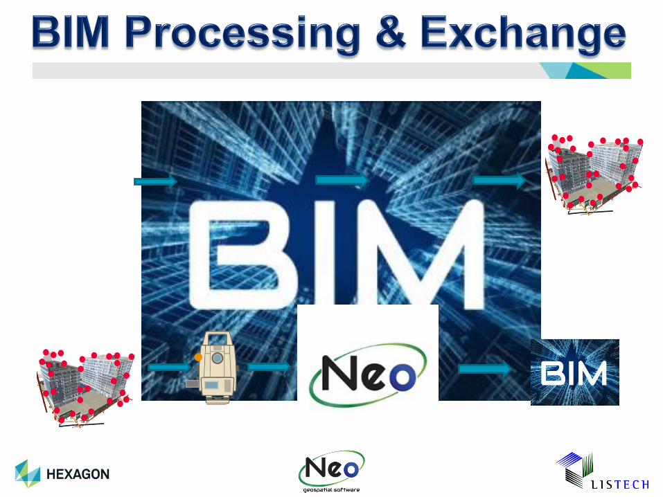
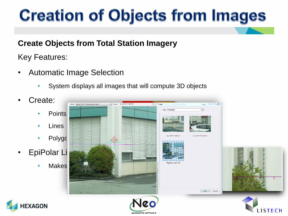
Create Objects from Total Station Imagery
Key Features:
• Automatic Image Selection
• System displays all images that will compute 3D objects
• Create:
• Points
• Lines
• Polygons
• EpiPolar Line
• Makes for easy digitising on second image
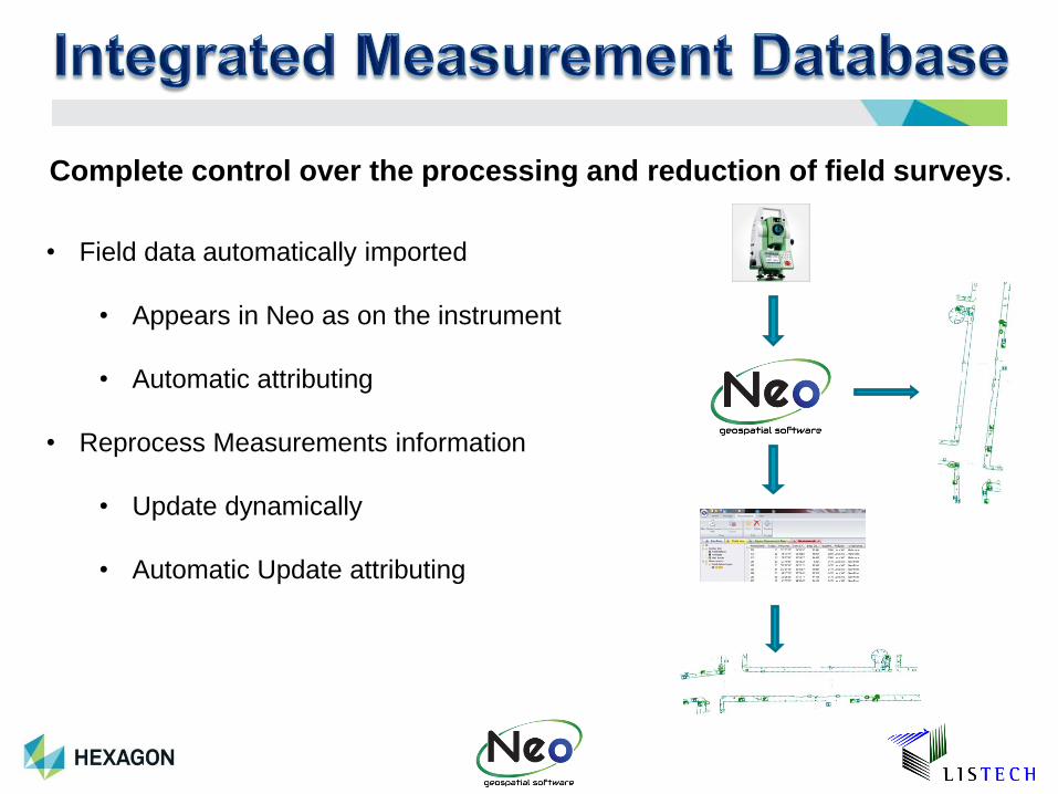
Complete control over the processing and reduction of field surveys.
• Field data automatically imported
• Appears in Neo as on the instrument
• Automatic attributing
• Reprocess Measurements information
• Update dynamically
• Automatic Update attributing
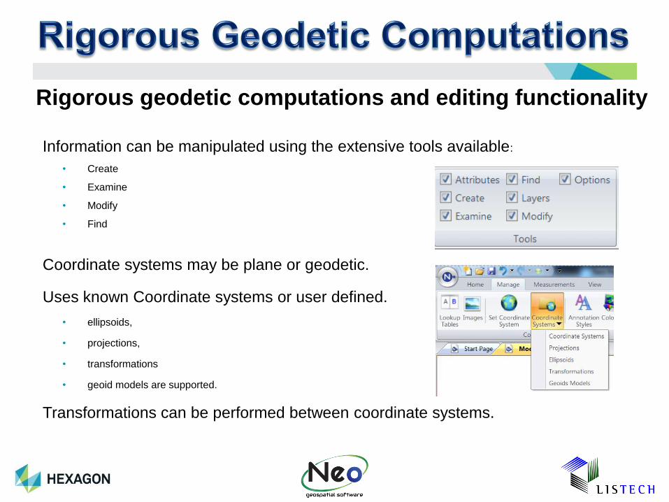
Information can be manipulated using the extensive tools available:
• Create
• Examine
• Modify
• Find
Coordinate systems may be plane or geodetic.
Uses known Coordinate systems or user defined.
• ellipsoids,
• projections,
• transformations
• geoid models are supported.
Transformations can be performed between coordinate systems.
Rigorous geodetic computations and editing functionality