controlling the outside world servo motor. servo motor a feedback controlled motor –the parallax...
TRANSCRIPT

Controlling the Outside World
Servo Motor
Servo motor
• A feedback controlled motor– The Parallax standard servo motor has built in
feedback– Range of motion is limited
• Parallax also supplies continuous servo motors for robotic applications but…
– This is not a continuous servo!• That is, it will not go 360º• It will hit “stops” at either direction around
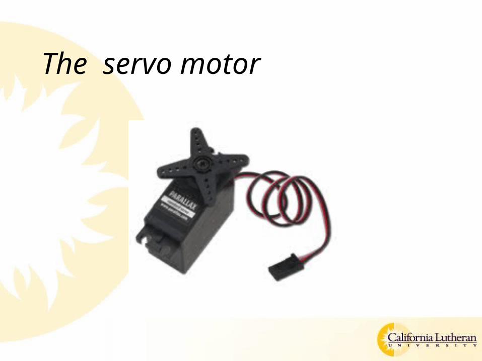
The servo motor
Wiring the servo motor
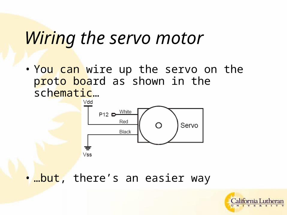
• You can wire up the servo on the proto board as shown in the schematic…
• …but, there’s an easier way
Wiring the servo motor
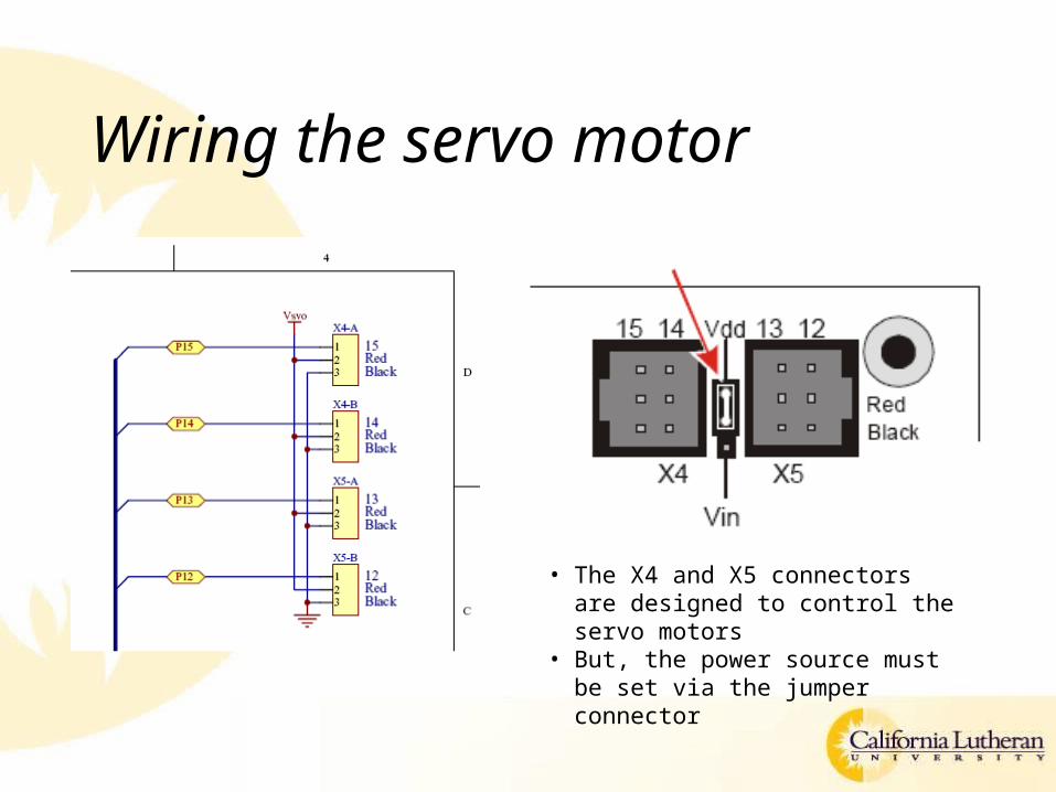
Wiring the servo motor
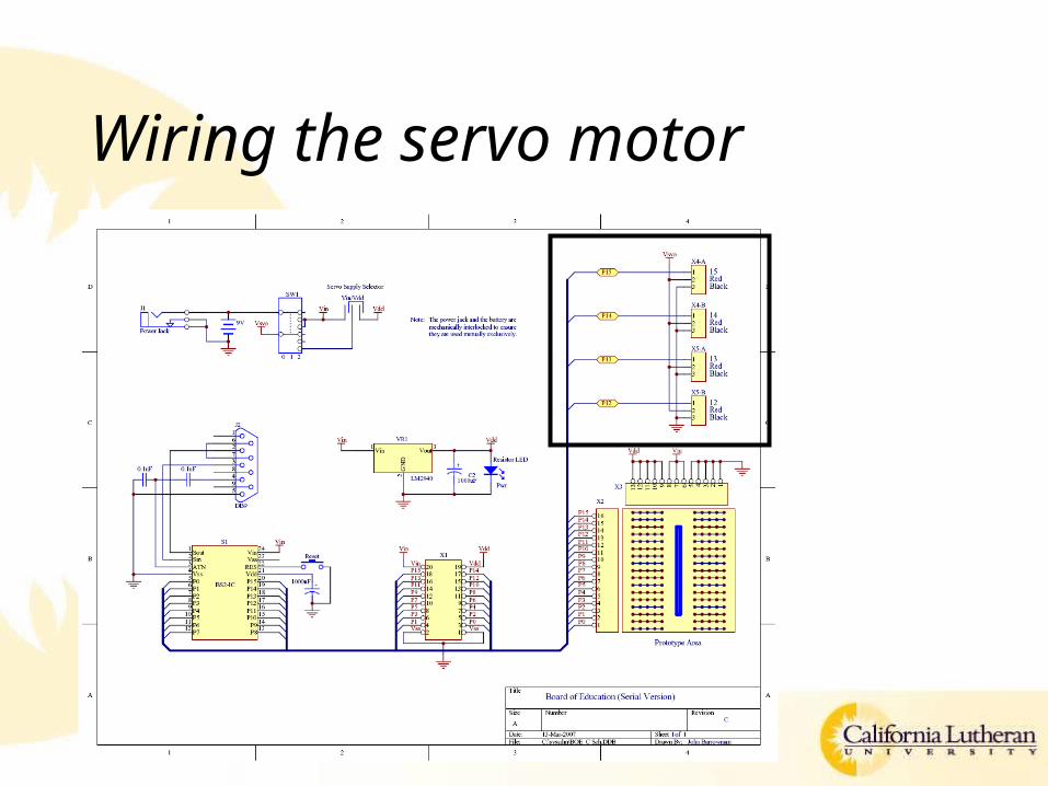
• The X4 and X5 connectors are designed to control the servo motors
• But, the power source must be set via the jumper connector
Power
• Check your power source!– If using a DC power blocks, it may be 9V or
it may be 6V– Set the Vdd/Vin jumper as specified
• Vdd if using a 9V source (or 9V battery)• Vin if using a 6V source
– Power switch must be in position 2 to send power to the X4/X5 (servo) connectors
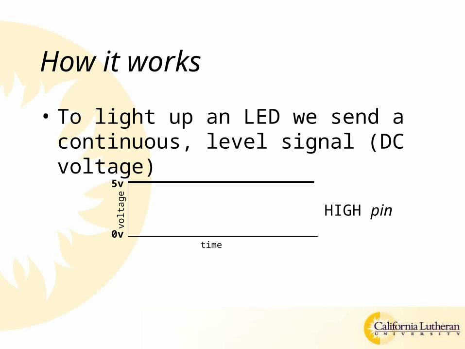
How it works
• To light up an LED we send a continuous, level signal (DC voltage)
0v
5v
volta
ge
time
HIGH pin
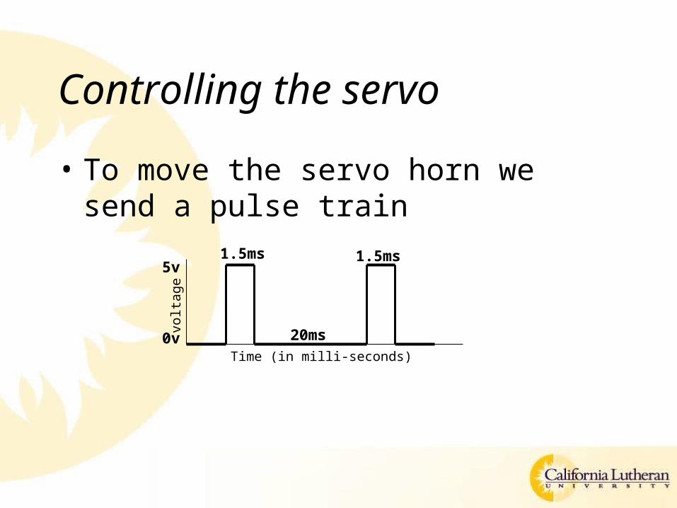
Controlling the servo
• To move the servo horn we send a pulse train
0v
5v
volta
ge
Time (in milli-seconds)
1.5ms 1.5ms
20ms
Controlling the servo
• The pulse width will control the location of the servo
• The time between pulses should be 20 milli-seconds
From PBASIC
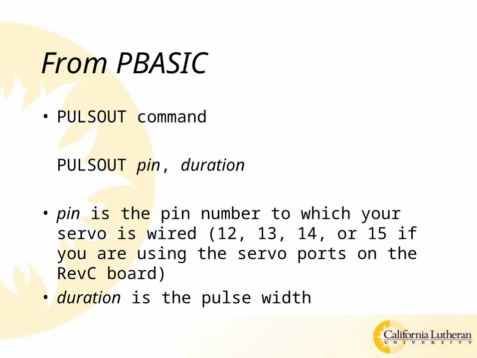
• PULSOUT command
PULSOUT pin, duration
• pin is the pin number to which your servo is wired (12, 13, 14, or 15 if you are using the servo ports on the RevC board)
• duration is the pulse width
PULSOUT command details
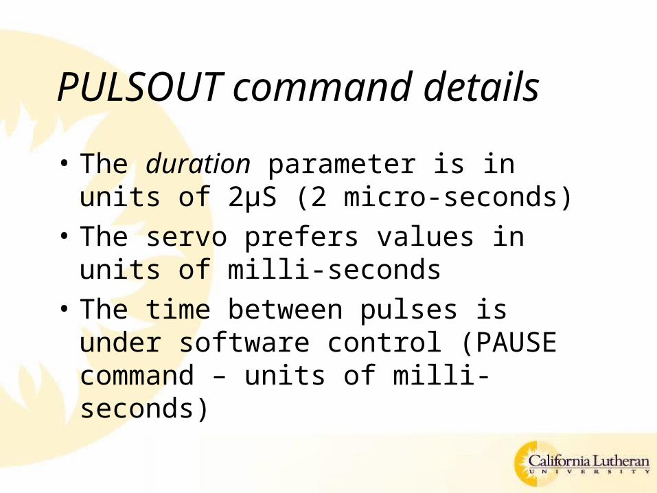
• The duration parameter is in units of 2μS (2 micro-seconds)
• The servo prefers values in units of milli-seconds
• The time between pulses is under software control (PAUSE command – units of milli-seconds)
Activity – in class
• Test the servo– Test all 4 servo ports
• Find the values of the duration parameter (in the PULSOUT command) that cause the servo to hit the stops in both the clockwise and counter-clockwise directions
Homework
• Design a system that continually moves the servo from one stop to the other– That is, it goes from full counter-clockwise to full clockwise and back again,
continuously• Add two buttons to the board (B1 and B2)
– B1 is the emergency stop (EStop)• When it is pressed all servo motion stops
– B2 is the reset button• When it is pressed the servo motion begins again
• Add two LEDs– The red LED lights when the servo is all the way clockwise– The green LED lights when the servo is all the way counterclockwise– Both LEDs are off (not lit) when the servo is somewhere between clockwise
and counterclockwise• The servo should not “slam” into the stops
Deliverables
• A state-machine diagram depicting the operation of the system
• Source code
• A schematic diagram of the circuit
• A working demonstration on the Basic Stamp development board (in class)