controlling speed of motor powered by solar energystc.fs.cvut.cz/pdf12/2532.pdfcontrolling speed of...
TRANSCRIPT
Řízení otáček elektrického motoru napájeného solární energií
Controlling speed of motor powered by solar energy
Bc. Zdeněk Novák1
Vedoucí práce: prof. Ing. Milan Hofreiter, CSc.2 Abstrakt Na téma řízení otáček motorů, které jsou napájeny pomocí elektřiny ze střídavé sítě, bylo již v historii vypracováno několik prací a lze toto téma považovat za dobře zmapovanou oblast. Existují však i konstrukce motorů, jenž nemusejí být napájeny stejnosměrným či střídavým proudem přímo ze sítě. Mezi takové motory patří i tzv. motor Mendocino. Tento motor levituje na magnetickém polštáři a je napájen pomocí solárních článků umístěných po obvodu jeho konstrukce. Cílem této práce je vyvinutí řídící jednotky, pomocí které bude možné měnit otáčky motoru Mendocino v závislosti na intenzitě dopadajícího světla. Tato jednotka bude komunikovat s počítačem a uživatel bude moci zadávat otáčky motoru v prostředí Simulink, které bude disponovat programovatelnými regulačními prvky navržené autorem. Jelikož není motor Mendocino běžně dostupný výrobek, bude nutné navrhnout konstrukci vhodnou do laboratorního prostředí a motor vyrobit. Keywords Mendocino motor, microcontroller, PCB, solar cell, electromagnetism, Simulink
1. Introduction The first idea of motor powered by solar energy - causing electromagnetic induction in its coils within magnetic field (and therefore its rotation) - came from the Bell telephone laboratories in 1962 [1]. Its description was made by Daril Chapyn. It was probably only an experimental device for presenting the sun as a source of power, because scientists just developed the modern photovoltaic cell (1953). At this time motor didn't levitated on magnetic cushion.. This was made later by Larry Spring in 1994, and because his experimental laboratory was located in Mendocino Coast, motor was named “Larry Spring's Magnetic Levitation Mendocino Brushless Solar Motor” or simply Mendocino motor [2].
Before the construction of motor itself, there are several tasks to do. Firstly, a controlling unit equiped with development kit is required. This unit will have to be able to collect data about speed of motor, send them to computer for computing next step in control process of regulation and after receiving an order from computer, setting the power of selected lamps (appropriately chosen to fit solar cells characteristics) to required level. Secondly, programming of Matlab Simulink application for future controlling of motor is necessary. The application has to be updated after construction of motor to fit its requirements. And thirdly, measurements of basic characteristics of solar cells have to be done for choosing adequate lamps and design of motor coils. Department of Instrumentation and Control Engineering, Faculty of Mechanical Engineering, Czech Technical University in Prague, Prague, Czech republic e-mail: [email protected]
There are further sidesteps, which will be described later in the text. The construction of motor is not hard, but due to its small dimensions, a little of patient and precision is required. Designing of motor should be made according to laws of electromagnetic induction for a better performance. Selecting appropriate materials and its dimensions is the key to success.
2. Design, construction and experiments
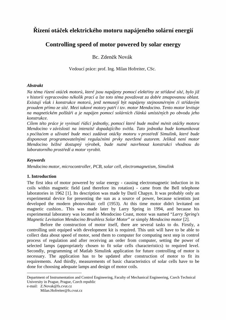
2.1 Development kit On market, there are already some development kits available. They are equipped with microcontroller unit, have various inputs and outputs and different kind of specific functions. The price varies from low price models (usually for specific purpose) to higher price models (usually universal purpose). Because one task of my thesis is to design my own control unit, I decided to make it as universal, due to future plans with this project (such as controlling motor from remote desktop). So far, laboratory of control engineering had to buy this kind of devices from the manufacturers, so the price of device was raised by profit of selling company. From now on, laboratory can become independent in this task, allowing to save some money in future projects. First step of designing circuit for development kit is choosing a microcontroller. Basically, this section determines what user will be able to do with kit in the future. For its good attributes, such as rewritable program flash memory and high speed core, the 8-bit microcontroller C8051F3401 was chosen. According to specifications of manufacturer and its original development kit [4], blueprint for controlling unit using TinyCad2 was drawn (Fig. 1). This kit is designed to connect to PC via USB or RS232, it has 32 input/output pins for wide range of usage, 2 pre-prepared pins for connecting buttons, 2 LEDs for monitoring program behavior and 1 pre-prepared section for PWM. Second step, after choosing all components in circuit, is designing printed circuit board (PCB). There are some important rules to follow, all can be found in [5]. To create PCB’s blueprint (Fig. 2), computer program FreePCB3 was used. This kind of PCB cannot be made with basic equipment of our laboratory, because it contains routes with width of 0, 2 mm. That’s why production of PCB was made as a contract by PragoBoard company and completed PCB is shown on Fig. 4 (left). Used technologies on bilateral PCB were solder mask, HAL (Hot Air Leveling), printing and electrical testing for blind holes and short circuits. Last step in production of development kit is assembling PCB with electronics. Even though PCB contains several SMD components; it was decided to do it in laboratory with using basic equipment for soldering, such as soldering iron, tweezers, tin, rosin and others. After this last step development kit was completed (Fig. 4 right) and ready for mounting to controlling unit and its programming.
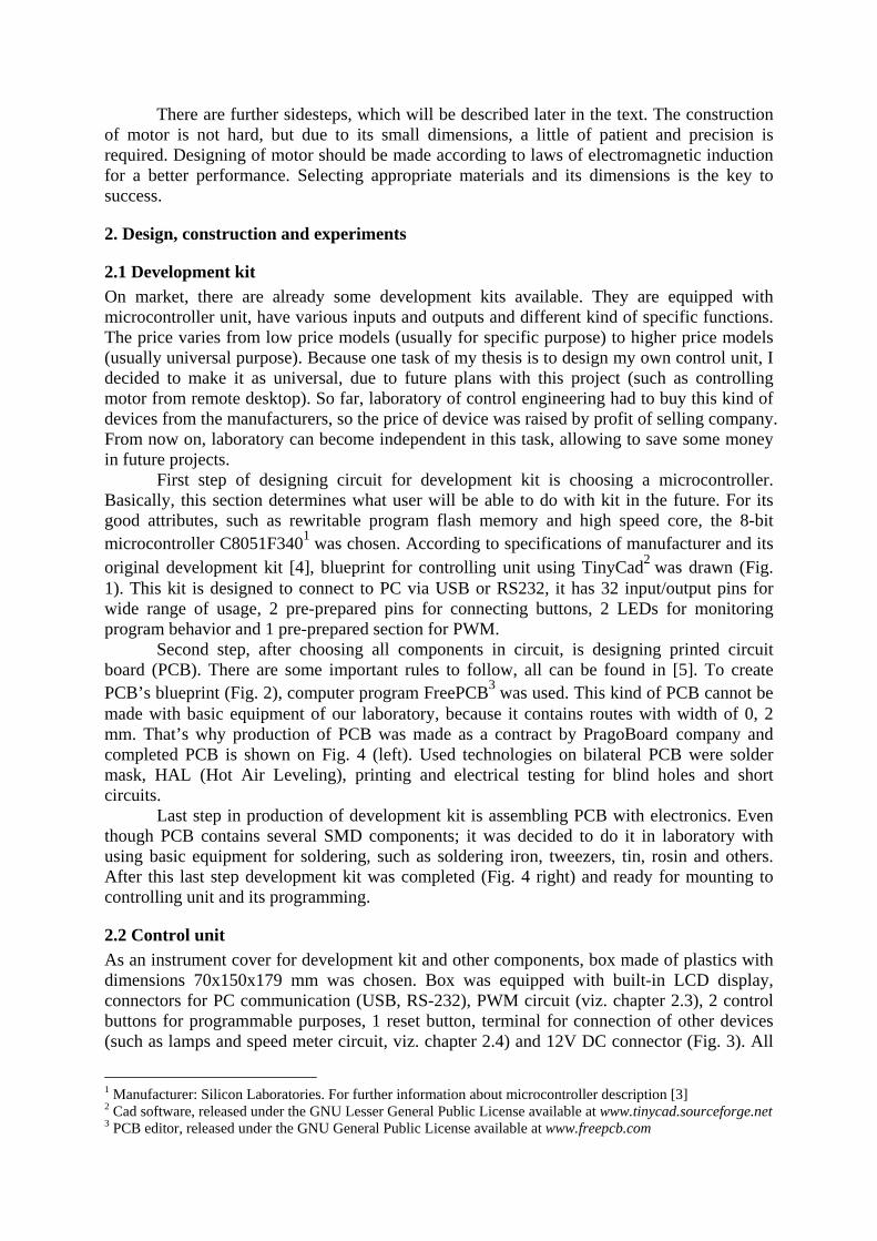
2.2 Control unit As an instrument cover for development kit and other components, box made of plastics with dimensions 70x150x179 mm was chosen. Box was equipped with built-in LCD display, connectors for PC communication (USB, RS-232), PWM circuit (viz. chapter 2.3), 2 control buttons for programmable purposes, 1 reset button, terminal for connection of other devices (such as lamps and speed meter circuit, viz. chapter 2.4) and 12V DC connector (Fig. 3). All
1 Manufacturer: Silicon Laboratories. For further information about microcontroller description [3] 2 Cad software, released under the GNU Lesser General Public License available at www.tinycad.sourceforge.net 3 PCB editor, released under the GNU General Public License available at www.freepcb.com
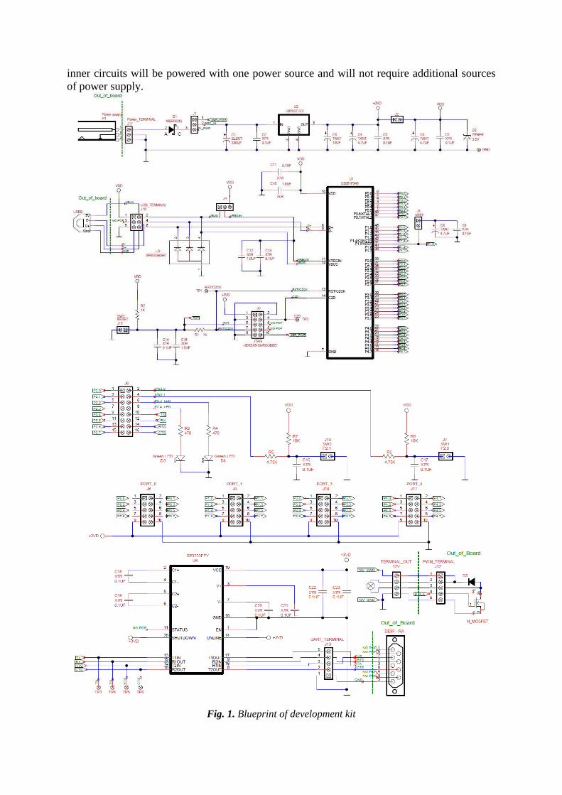
inner circuits will be powered with one power source and will not require additional sources of power supply.
Fig. 1. Blueprint of development kit
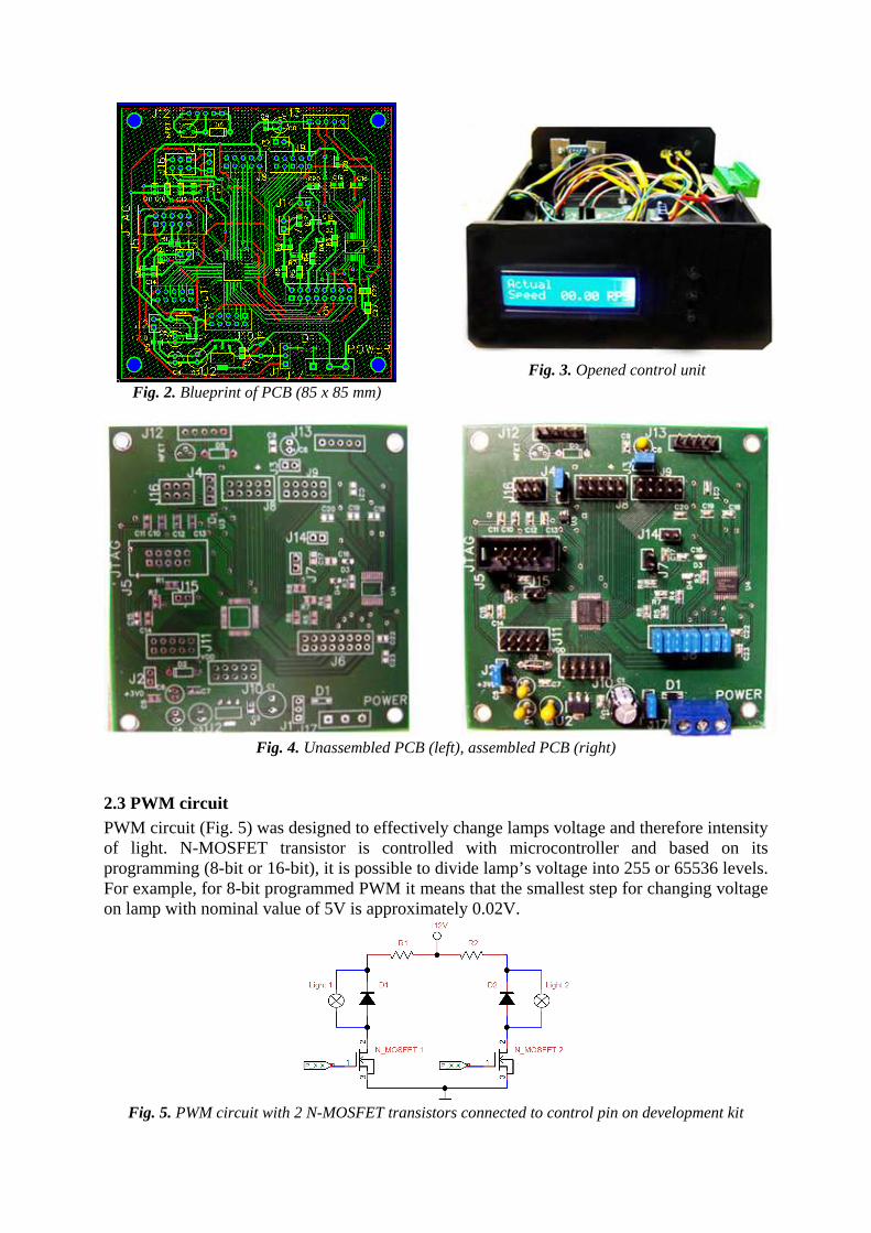
Fig. 3. Opened control unit
Fig. 2. Blueprint of PCB (85 x 85 mm)
Fig. 4. Unassembled PCB (left), assembled PCB (right)
2.3 PWM circuit PWM circuit (Fig. 5) was designed to effectively change lamps voltage and therefore intensity of light. N-MOSFET transistor is controlled with microcontroller and based on its programming (8-bit or 16-bit), it is possible to divide lamp’s voltage into 255 or 65536 levels. For example, for 8-bit programmed PWM it means that the smallest step for changing voltage on lamp with nominal value of 5V is approximately 0.02V.
Fig. 5. PWM circuit with 2 N-MOSFET transistors connected to control pin on development kit
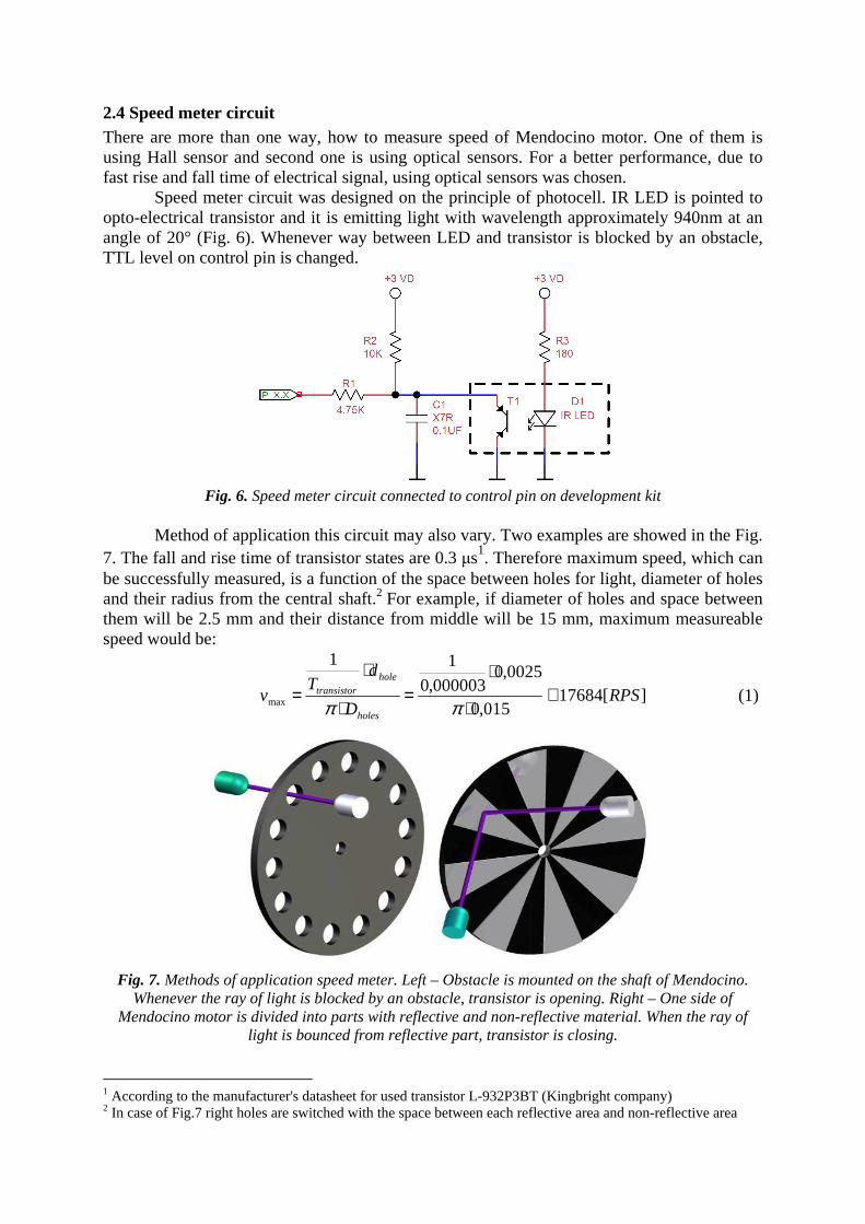
2.4 Speed meter circuit There are more than one way, how to measure speed of Mendocino motor. One of them is using Hall sensor and second one is using optical sensors. For a better performance, due to fast rise and fall time of electrical signal, using optical sensors was chosen.
Speed meter circuit was designed on the principle of photocell. IR LED is pointed to opto-electrical transistor and it is emitting light with wavelength approximately 940nm at an angle of 20° (Fig. 6). Whenever way between LED and transistor is blocked by an obstacle, TTL level on control pin is changed.
Fig. 6. Speed meter circuit connected to control pin on development kit
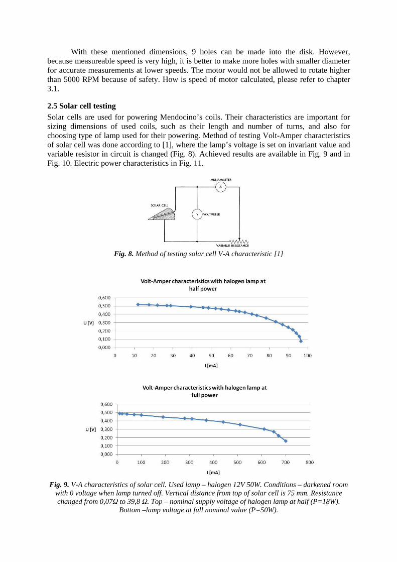
Method of application this circuit may also vary. Two examples are showed in the Fig.
7. The fall and rise time of transistor states are 0.3 µs1. Therefore maximum speed, which can be successfully measured, is a function of the space between holes for light, diameter of holes and their radius from the central shaft.2 For example, if diameter of holes and space between them will be 2.5 mm and their distance from middle will be 15 mm, maximum measureable speed would be:
][17684
015,0
0025,0000003,0
11
max RPSD
dT
vholes
holetransistor ≅
⋅
⋅=
⋅
⋅=
ππ
(1)
Fig. 7. Methods of application speed meter. Left – Obstacle is mounted on the shaft of Mendocino.
Whenever the ray of light is blocked by an obstacle, transistor is opening. Right – One side of Mendocino motor is divided into parts with reflective and non-reflective material. When the ray of
light is bounced from reflective part, transistor is closing.
1 According to the manufacturer's datasheet for used transistor L-932P3BT (Kingbright company) 2 In case of Fig.7 right holes are switched with the space between each reflective area and non-reflective area
With these mentioned dimensions, 9 holes can be made into the disk. However, because measureable speed is very high, it is better to make more holes with smaller diameter for accurate measurements at lower speeds. The motor would not be allowed to rotate higher than 5000 RPM because of safety. How is speed of motor calculated, please refer to chapter 3.1.
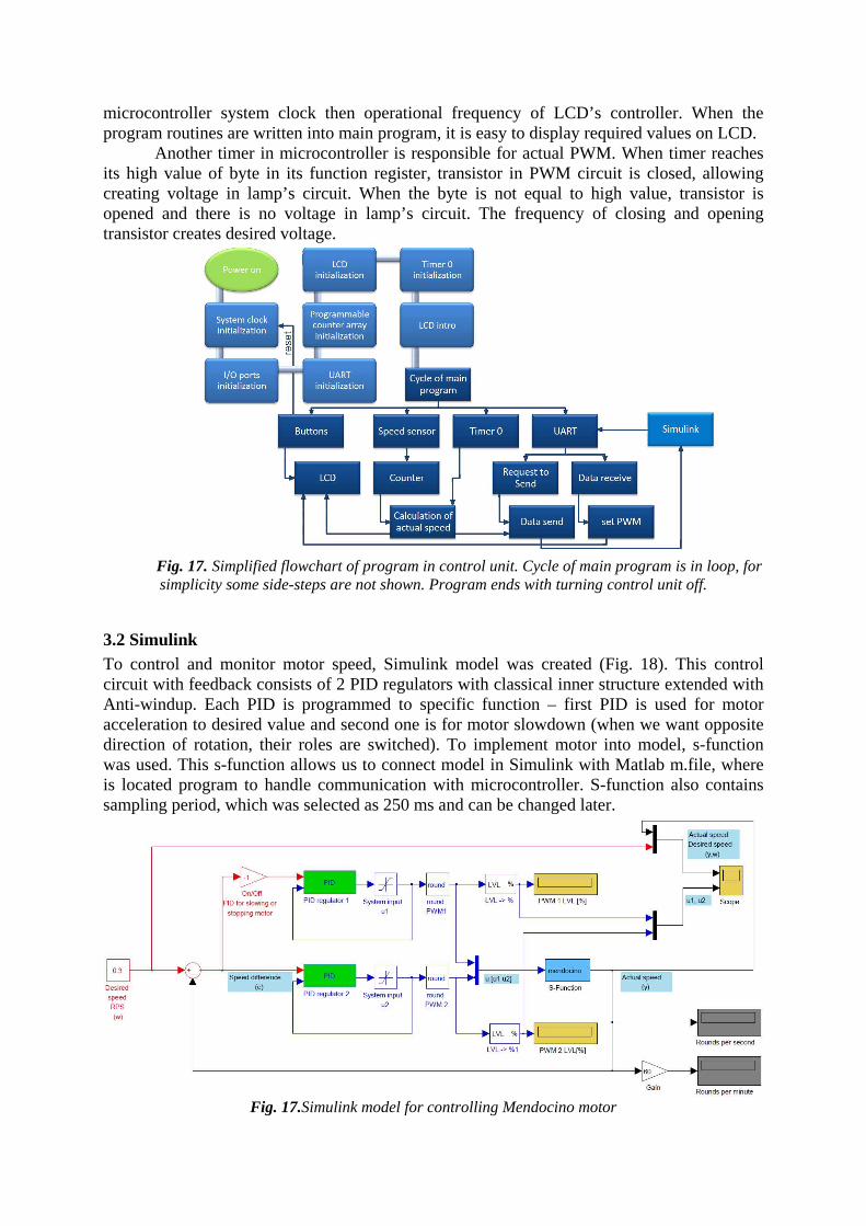
2.5 Solar cell testing Solar cells are used for powering Mendocino’s coils. Their characteristics are important for sizing dimensions of used coils, such as their length and number of turns, and also for choosing type of lamp used for their powering. Method of testing Volt-Amper characteristics of solar cell was done according to [1], where the lamp’s voltage is set on invariant value and variable resistor in circuit is changed (Fig. 8). Achieved results are available in Fig. 9 and in Fig. 10. Electric power characteristics in Fig. 11.
Fig. 8. Method of testing solar cell V-A characteristic [1]
Fig. 9. V-A characteristics of solar cell. Used lamp – halogen 12V 50W. Conditions – darkened room
with 0 voltage when lamp turned off. Vertical distance from top of solar cell is 75 mm. Resistance changed from 0,07Ω to 39,8 Ω. Top – nominal supply voltage of halogen lamp at half (P=18W).
Bottom –lamp voltage at full nominal value (P=50W).

Fig. 10. V-A characteristics of solar cell. Used lamps – 2 high power LED (one with 1.6V), white light. Conditions – darkened room with 0 voltage when LEDs turned off. Vertical distance from top of solar
cell is 5 mm. Resistance changed from 0,07Ω to 39,8 Ω. Both LED at nominal values of voltage.
Fig. 11. Electric power characteristics of solar cell for previous settings from Fig. 9 and 10. Top –
Pmax=28,643 mW, U=0,403 V, I=71 mA; middle - Pmax=184,83 mW, U=0,303 V, I=610 mA; bottom- Pmax=20,162 mW, U=0,414 V, I=48,7 mA

Because in the real model, electrical resistance of coil will be permanent (change of resistance with heat can be neglected), another characteristics have been done. In this case, only with voltmeter plugged in circuit and one stable resistor. Taken characteristics are available in Fig. 12 and Fig. 13. Also it should be mentioned, that solar cells have different efficiency with different wavelength of used light [6].
Fig. 12. V-A characteristics of solar cell. Used
lamps – 2 high power LED (one with 1.6V), white lamp. Conditions – darkened room with
0 voltage when LEDs turned off. Vertical distance from top of solar cell is 5 mm. Voltage
on LEDs changing from bottom value to top value (nominal voltage). Used electrical
resistance in circuit is 5,2 Ω. Solar cell inner electrical resistance is equal to 0,2 Ω.
Fig. 13. V-A characteristics of solar cell. Used lamp – halogen 12V 50W. Conditions –
darkened room with 0 voltage when lamp turned off. Vertical distance from top of solar
cell is 75 mm. Voltage on halogen lamp changing from bottom value to top value
(nominal voltage). Used electrical resistance in circuit is 20 Ω. Solar cell inner electrical
resistance is equal to 0,2 Ω.
2.6 Mendocino motor1 Basic concept of motor is shown in Fig. 14 and its principle can be found in Fig. 15.
Fig. 14.Concept of Mendocino motor – motor is levitating above 2 neodymium magnets, which are
replacing the bearings for no friction. Function of central neodymium magnet is described in Fig. 14. Because of opposite poles of neodymium magnets, motor is pushed towards the wall, making it stable
in one position. There are several upgrades that can be made to improve its performance, such as adding more magnets and lamps around to create higher voltage on solar cells.
1 At a time of the deadline for this paper for Students conference 2012, Mendocino motor concept is finished. Parts of motor will be built in upcoming days and hopefully - after assembling - real motor will be shown during the conference. For that reason, please accept my apologies for no pictures of real model.

Fig. 15.Principle of the Mendocino motor with inner coil - every coil is connected to the opposite
solar panel as shown above. Turning one of lamps on creates voltage on desired solar panel. Current will start to flow through circuit, causing magnetic induction inside and outside of coil. Directions of
magnetic field lines depend on a direction of current in circuit and inside of coil these lines are parallel. Permanent neodymium magnet is located under motor. If the lines of magnetic induction
have same direction as lines of magnet, attractive force will appear, making motor to rotate clockwise (lamp 1 turned on). If the same lines have opposite direction, then repulsive force will come in action and try to switch sides of coil to the right direction (S pole of coil to N pole of magnet), making motor
to rotate under clockwise (lamp 2 turned on). That allows us to spin Mendocino motor, create our wanted direction of rotation or simply slowing down motor to required speed.
Magnetic induction in case of coil with solenoid shape can be described as [7]:
selenoidl
INB
⋅⋅= 0µ
(2)
The magnetic moment for coil is [7]:
BxSINMrr
⋅⋅=
(3)
And another important equation is wire resistance, equal to [7]:
S
lR conductor⋅= ρ
(4)
Because winding of coil is not in whole section inside of Mendocino motor, it can be designed as Brooks coil, which is a type of multilayer coil (Fig. 16 left). Optimal proportions of coil without core for highest inductance are [8]:
2016994,023
Nc
L ⋅⋅=
(5)
Or we can use Wheeler’s formula for short cross-wound coil (Fig. 16 right) [9]:
bar
NrL
1096315,0 22
++⋅⋅=
(6)

Fig. 16.Brooks coil (left), Cross-wound coil (right)
These equations are required for designing optimal coil’s length and cross-section; otherwise magnetic moment would not be large enough to spin motor. Also, light weight of its structure is necessary. That’s why it should be made of light materials such as aluminum or Plexiglas.
However, solar panels are rotating and the lamp is shining on one or two of them (based on lamp’s location), therefore voltage in circuit is not permanent. Also, transient phenomenon of RL circuit occurs. This part of theory requires more investigation.
3. Programming
3.1 Development kit and its accessories It was necessary to program microcontroller for wide range of purposes. As a development environment Silicon Laboratories IDE was used. Because this program is distributed by microcontroller’s manufacturer, it allows user to easily implement SFR register of microcontroller and directly download program code into its programmable flash memory. Used programming language has been C++. Microcontroller is programmed for these main functions:
- Half-duplex communication with computer - handling operation of LCD, where user can choose between information about
actual speed (in RPS) or actual power in lamps (in percents from 0%-100%) - setting PWM to control value of voltage on lamps - calculating actual speed based on speed meter settings Microcontroller was set to use system clock equaled to its high oscillator frequency of
12 Mhz. Because of its pipeline instruction architecture, it executes 70% of instructions in 1 or 2 system clocks [3]. That gives us enough of processing power to handle all these tasks mentioned above.
For calculating speed, one of the microcontroller timers was used. Now, it is programmed to measure time interval of 250 ms and it can be change in the future. Accuracy of this time interval is given by accuracy of internal oscillator which is %25,0± . Signals from speed meter causes on selected pin (set to edge sensitive) of microcontroller an interrupt and when the time reach its interval of 250 ms, microcontroller simply computes speed based on number of interrupts in the time interval.
Because computer is programmed as master device, when it sends specific byte to microcontroller serial buffer, microcontroller is responding with sending computed speed to computer. Before this request, computer is always sending settings of actual PWM to set. So the whole code send from computer to microcontroller can be explained as “PWM1PWM2RequestingByteForSpeed”.
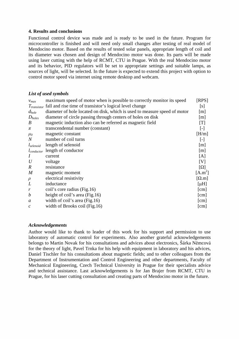
Programming of LCD has its own rules, primarily based on timing of communication between microcontroller and LCD’s controller. This is caused by higher frequency of
microcontroller system clock then operational frequency of LCD’s controller. When the program routines are written into main program, it is easy to display required values on LCD.
Another timer in microcontroller is responsible for actual PWM. When timer reaches its high value of byte in its function register, transistor in PWM circuit is closed, allowing creating voltage in lamp’s circuit. When the byte is not equal to high value, transistor is opened and there is no voltage in lamp’s circuit. The frequency of closing and opening transistor creates desired voltage.
Fig. 17. Simplified flowchart of program in control unit. Cycle of main program is in loop, for simplicity some side-steps are not shown. Program ends with turning control unit off.
3.2 Simulink To control and monitor motor speed, Simulink model was created (Fig. 18). This control circuit with feedback consists of 2 PID regulators with classical inner structure extended with Anti-windup. Each PID is programmed to specific function – first PID is used for motor acceleration to desired value and second one is for motor slowdown (when we want opposite direction of rotation, their roles are switched). To implement motor into model, s-function was used. This s-function allows us to connect model in Simulink with Matlab m.file, where is located program to handle communication with microcontroller. S-function also contains sampling period, which was selected as 250 ms and can be changed later.
Fig. 17.Simulink model for controlling Mendocino motor
4. Results and conclusions Functional control device was made and is ready to be used in the future. Program for microcontroller is finished and will need only small changes after testing of real model of Mendocino motor. Based on the results of tested solar panels, appropriate length of coil and its diameter was chosen and design of Mendocino motor was done. Its parts will be made using laser cutting with the help of RCMT, CTU in Prague. With the real Mendocino motor and its behavior, PID regulators will be set to appropriate settings and suitable lamps, as sources of light, will be selected. In the future is expected to extend this project with option to control motor speed via internet using remote desktop and webcam. List of used symbols vmax maximum speed of motor when is possible to correctly monitor its speed [RPS] Ttransistor fall and rise time of transistor’s logical level change [s] dhole diameter of hole located on disk, which is used to measure speed of motor [m] Dholes diameter of circle passing through centers of holes on disk [m] B magnetic induction also can be referred as magnetic field [T] π transcendental number (constant) [-] µ0 magnetic constant [H/m] N number of coil turns [-] lselenoid length of selenoid [m] lconductor length of conductor [m] I current [A] U voltage [V] R resistance [Ω] M magnetic moment [A.m2] ρ electrical resistivity [Ω.m] L inductance [µH] r coil’s core radius (Fig.16) [cm] b height of coil’s area (Fig.16) [cm] a width of coil’s area (Fig.16) [cm] c width of Brooks coil (Fig.16) [cm] Acknowledgements Author would like to thank to leader of this work for his support and permission to use laboratory of automatic control for experiments. Also another grateful acknowledgements belongs to Martin Novak for his consultations and advices about electronics, Šárka Němcová for the theory of light, Pavel Trnka for his help with equipment in laboratory and his advices, Daniel Tischler for his consultations about magnetic fields; and to other colleagues from the Department of Instrumentation and Control Engineering and other departments, Faculty of Mechanical Engineering, Czech Technical University in Prague for their specialists advice and technical assistance. Last acknowledgements is for Jan Brajer from RCMT, CTU in Prague, for his laser cutting consultation and creating parts of Mendocino motor in the future.

References [1] CHAPIN, Daryl M. BELL TELEPHONE LABORATORIES. Energy from the sun. 4th
edition. Baltimore: Waverly Press, 1964. [2] Larryspring.com: Motors. Larryspring School of common sense physics [online]. [cit.
2012-03-17]. Available at: http://www.larryspring.com/sub06_motors.html [3] C8051F34x Data Sheet [online pdf], Austin (Texas): Silicon Laboratiories Inc.,
10.7.2009 [cit. 17.2.2012 ]. Datasheet of C8051F340. Available at: <http://www.silabs.com/support/pages/support.aspx?ProductFamily=USB+MCUs>
[4] C8051F34x-DK User Guide [online pdf], Austin (Texas): Silicon Laboratiories Inc.,
10.7.2009 [cit. 17.2.2012 ]. Datasheet of development kit C8051F340. Available at: <http://www.silabs.com/support/pages/support.aspx?ProductFamily=USB+MCUs>
[5] ZÁHLAVA, Vít. Návrh a konstrukce desek plošných spojů: principy a pravidla
praktického návrhu. Praha: BEN - technická literatura, 2010. ISBN 978-80-7300-266-4.
[6] HABEL, Jiří. Základy světelné techniky (4): Základy fotometrie (1.část). Světlo 3, pp
44-48 (2009). Available at <http://www.odbornecasopisy.cz/res/pdf/39195.pdf> [7] SOPKO, Bruno, Ladislav SAMEK a František ČERNÝ. Fyzika 2. Praha:
Vydavatelství ČVUT, 2005. ISBN 80-01-03194-2. [8] GROWER, Frederick W. Inductance Calculations. Mineola,N.Y: Dover phoenix
Editions, 2004. ISBN 0-486-49577-9. [9] LANGFORD-SMITH, Fritz. AMALGAMATED WIRELESS VALVE COMPANY.
Radiotron Designer's Handbook. Reproduced and Distributed by Radio Corporation of America (1960). Originally printed in Glebe (Australia): Wireless Press, 1952. fourth edition.