contribution to the wwh-obd gtr with regard to the ... · with regard to the implementation of...
TRANSCRIPT
Transmitted by the expert from ISO Informal document No. GRPE-52-12 (52nd GRPE, 6-9 June 2006,
agenda item 1.3.)
CONTRIBUTION to the WWH-OBD gtr With regard to the implementation of WWH-OBD communication requirements, draft document ISO/PDPAS 27145-1.4. (part 1 to part 4) have been made available to GRPE secretariat and to GRPE experts for being referenced in the WWH-OBD gtr. As these parts are voluminous, they will not be distributed as a paper version during the 52nd GRPE session. However, all four parts are electronically attached to this informal document and can be consulted or downloaded from the GRPE website at the address: http://www.unece.org/trans/main/wp29/wp29wgs/wp29grpe/grpeinf52.html
- - - - -
© ISO 2006 – All rights reserved
Document type: Publicly Available Specification Document subtype: Document stage: (20) Preparatory Document language: E C:\WWH-obd\GENEVA 2006_06\prepa meeting\ISO_PAS_27145-1.4_(E)_WWH-OBD_GIUC_RevOn_2006-04-27.doc STD Version 2.1c2
ISO TC 22/SC 3 N Date: 2006-04-27
ISO/PDPAS 27145-1.4
ISO TC 22/SC 3/WG 1
Secretariat: DIN
Road vehicles — Implementation of WWH-OBD communication requirements — Part 1: General information and use case definition
Élément introductif — Élément central — Partie 1: Titre de la partie
Warning
This document is not an ISO International Standard. It is distributed for review and comment. It is subject to change without notice and may not be referred to as an International Standard.
Recipients of this draft are invited to submit, with their comments, notification of any relevant patent rights of which they are aware and to provide supporting documentation.
ISO/PDPAS 27145-1.4
ii © ISO 2006 – All rights reserved
Copyright notice
This ISO document is a working draft or committee draft and is copyright-protected by ISO. While the reproduction of working drafts or committee drafts in any form for use by participants in the ISO standards development process is permitted without prior permission from ISO, neither this document nor any extract from it may be reproduced, stored or transmitted in any form for any other purpose without prior written permission from ISO.
Requests for permission to reproduce this document for the purpose of selling it should be addressed as shown below or to ISO's member body in the country of the requester:
[Indicate the full address, telephone number, fax number, telex number, and electronic mail address, as appropriate, of the Copyright Manger of the ISO member body responsible for the secretariat of the TC or SC within the framework of which the working document has been prepared.]
Reproduction for sales purposes may be subject to royalty payments or a licensing agreement.
Violators may be prosecuted.
ISO/PDPAS 27145-1.4
© ISO 2006 – All rights reserved iii
Contents Page
1 Scope ......................................................................................................................................................1 2 Normative references............................................................................................................................1 3 Terms and definitions ...........................................................................................................................2 4 Symbols and abbreviated terms ..........................................................................................................3 5 Conventions...........................................................................................................................................3 6 Document overview...............................................................................................................................4 7 Use case description.............................................................................................................................5 7.1 Overview.................................................................................................................................................5 7.2 Emissions-related use cases ...............................................................................................................5 7.2.1 Use case summary ................................................................................................................................5 7.2.2 Use case 1 – Information about the emissions-related OBD system state .....................................5 7.2.3 Use case 2 – Information about active and confirmed emission-related malfunctions.................6 7.2.4 Use case 3 – Information related to diagnosis for the purpose of repair........................................6 8 Vehicle On-Board Diagnostic (VOBD) .................................................................................................7 8.1 VOBD definition .....................................................................................................................................7 8.2 VOBD system.........................................................................................................................................7 8.3 VOBD data set........................................................................................................................................9 8.4 VOBD access method .........................................................................................................................10 8.4.1 Overview...............................................................................................................................................10 8.4.2 VOBD data caching mode...................................................................................................................10 8.4.3 VOBD direct data mode ......................................................................................................................13
ISO/PDPAS 27145-1.4
iv © ISO 2006 – All rights reserved
Foreword
ISO (the International Organization for Standardization) is a worldwide federation of national standards bodies (ISO member bodies). The work of preparing International Standards is normally carried out through ISO technical committees. Each member body interested in a subject for which a technical committee has been established has the right to be represented on that committee. International organizations, governmental and non-governmental, in liaison with ISO, also take part in the work. ISO collaborates closely with the International Electrotechnical Commission (IEC) on all matters of electrotechnical standardization.
International Standards are drafted in accordance with the rules given in the ISO/IEC Directives, Part 2.
The main task of technical committees is to prepare International Standards. Draft International Standards adopted by the technical committees are circulated to the member bodies for voting. Publication as an International Standard requires approval by at least 75 % of the member bodies casting a vote.
In other circumstances, particularly when there is an urgent market requirement for such documents, a technical committee may decide to publish other types of normative document:
— an ISO Publicly Available Specification (ISO/PAS) represents an agreement between technical experts in an ISO working group and is accepted for publication if it is approved by more than 50 % of the members of the parent committee casting a vote;
— an ISO Technical Specification (ISO/TS) represents an agreement between the members of a technical committee and is accepted for publication if it is approved by 2/3 of the members of the committee casting a vote.
An ISO/PAS or ISO/TS is reviewed after three years in order to decide whether it will be confirmed for a further three years, revised to become an International Standard, or withdrawn. If the ISO/PAS or ISO/TS is confirmed, it is reviewed again after a further three years, at which time it must either be transformed into an International Standard or be withdrawn.
Attention is drawn to the possibility that some of the elements of this document may be the subject of patent rights. ISO shall not be held responsible for identifying any or all such patent rights.
ISO/PAS 27145-1 was prepared by Technical Committee ISO/TC 22, Road vehicles, Subcommittee SC 3, Electrical and electronic equipment.
ISO/PAS 27145 consists of the following parts, under the general title Road vehicles — Implementation of WWH-OBD communication requirements:
Part 1: General information and use case definition
Part 2: Common emissions-related data dictionary
Part 3: Common message dictionary
Part 4: Connection between vehicle and test equipment
Part 5: External test equipment
NOTE Part 4 of the standard will be extended as necessary due to introduction of additional communication media.
ISO/PDPAS 27145-1.4
© ISO 2006 – All rights reserved v
Introduction
This document set includes the communication between the vehicle's OBD systems and test equipment implemented across vehicles within the scope of the WWH-OBD GTR (World Wide Harmonized On-Board Diagnostics Global Technical Regulations).
It has been established in order to apply the unified diagnostic services (specified in ISO 14229-1 Road vehicles – Unified diagnostic services (UDS) – Part 1: Specification and requirements) to WWH OBD systems.
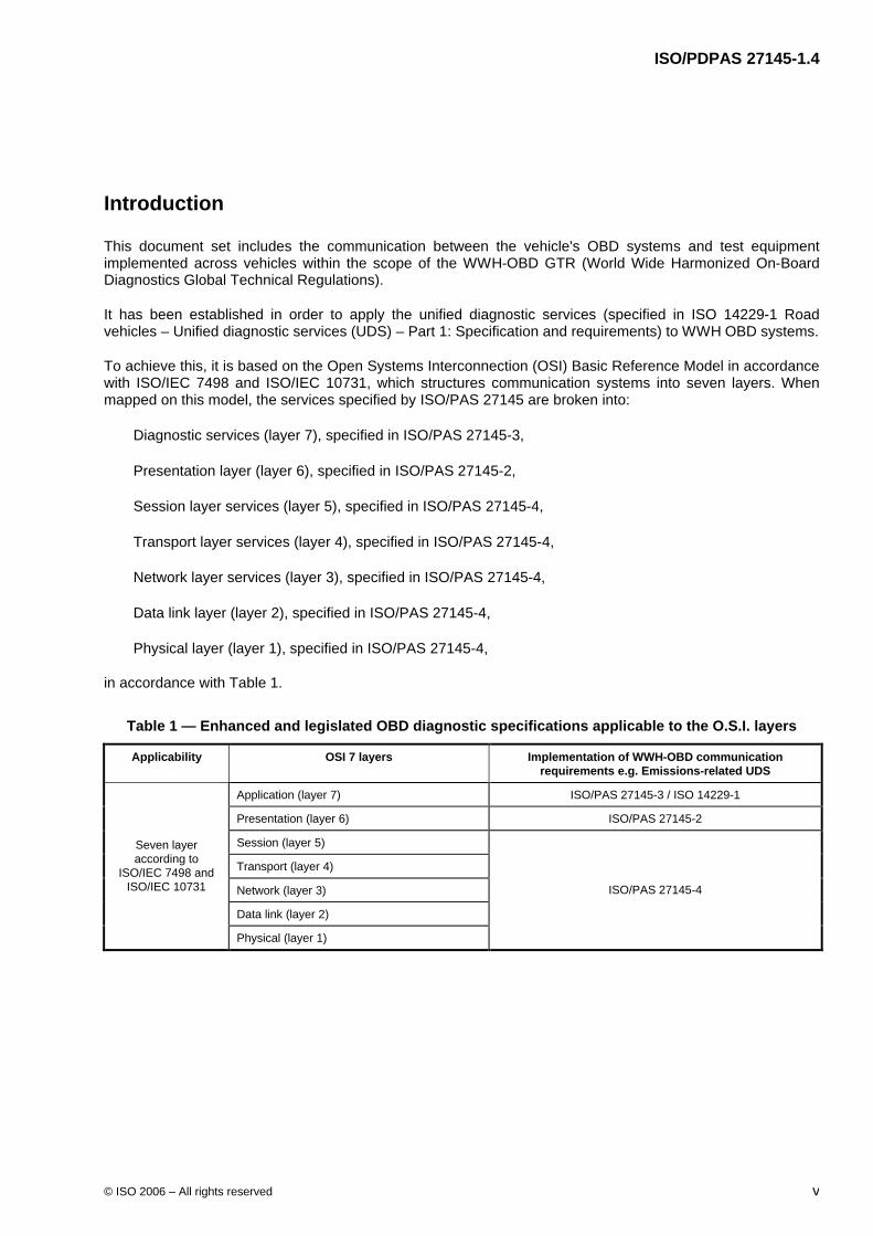
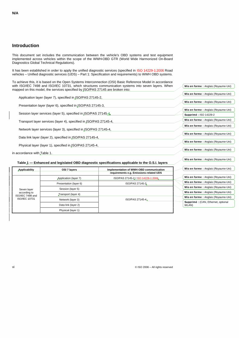
To achieve this, it is based on the Open Systems Interconnection (OSI) Basic Reference Model in accordance with ISO/IEC 7498 and ISO/IEC 10731, which structures communication systems into seven layers. When mapped on this model, the services specified by ISO/PAS 27145 are broken into:
Diagnostic services (layer 7), specified in ISO/PAS 27145-3,
Presentation layer (layer 6), specified in ISO/PAS 27145-2,
Session layer services (layer 5), specified in ISO/PAS 27145-4,
Transport layer services (layer 4), specified in ISO/PAS 27145-4,
Network layer services (layer 3), specified in ISO/PAS 27145-4,
Data link layer (layer 2), specified in ISO/PAS 27145-4,
Physical layer (layer 1), specified in ISO/PAS 27145-4,
in accordance with Table 1.
Table 1 — Enhanced and legislated OBD diagnostic specifications applicable to the O.S.I. layers
Applicability OSI 7 layers Implementation of WWH-OBD communication requirements e.g. Emissions-related UDS
Application (layer 7) ISO/PAS 27145-3 / ISO 14229-1
Presentation (layer 6) ISO/PAS 27145-2
Session (layer 5)
Transport (layer 4)
Network (layer 3)
Data link (layer 2)
Seven layer according to
ISO/IEC 7498 and ISO/IEC 10731
Physical (layer 1)
ISO/PAS 27145-4

WORKING DRAFT ISO/PDPAS 27145-1.4
© ISO 2006 – All rights reserved 1
Road vehicles — Implementation of WWH-OBD communication requirements — Part 1: General information and use case definition
1 Scope
Part 1: General Information and use case definition of ISO/PAS 27145 gives an overview of the structure and the partitioning of the different parts of this standard and shows the relation between the parts. In addition it outlines the use case scenarios where the ISO/PAS 27145 document set will be used. All terminology that is common throughout the ISO/PAS 27145 document set is also outlined here.
ISO/PAS 27145 is intended to become the single communication standard for access to OBD – related information. To allow for a smooth migration from the existing communication standards to this future world-wide standardised communication standard the initial communication concept will be based on CAN. In a second step ISO/PAS 27145 will be extended to define the world-wide harmonised OBD communication standard based on existing industry communications standards (e.g. Internet Protocol) over Ethernet. Due to the usage of standard network layer protocols, future extensions to optional physical layers (e.g. wireless) are possible.
2 Normative references
The following referenced documents are indispensable for the application of this document. For dated references, only the edition cited applies. For undated references, the latest edition of the referenced document (including any amendments) applies.
ISO 7498-1:1984, Information processing systems - Open systems interconnection - Basic reference model
ISO/IEC 10731:1994, Information technology -- Open Systems Interconnection -- Basic Reference Model -- Conventions for the definition of OSI services
ISO 4092:1988/, Road vehicles - Testers for motor vehicles - Vocabulary Technical Corrigendum 1 Cor.1:1991
ISO 14229-1:2006, Road vehicles — Unified diagnostic services (UDS) — Part 1: Specification and requirements
ISO/PAS 27145-2, Road vehicles — Implementation of WWH-OBD communication requirements — Part 2: Common emissions-related data dictionary
ISO/PAS 27145-3, Road vehicles — Implementation of WWH-OBD communication requirements — Part 3: Common message dictionary
ISO/PAS 27145-4, Road vehicles — Implementation of WWH-OBD communication requirements — Part 4: Connection between vehicle and test equipment
ISO/PAS 27145-5, Road vehicles — Implementation of WWH-OBD communication requirements — Part 5: External test equipment
ISO/PDPAS 27145-1.4
2 © ISO 2006 – All rights reserved
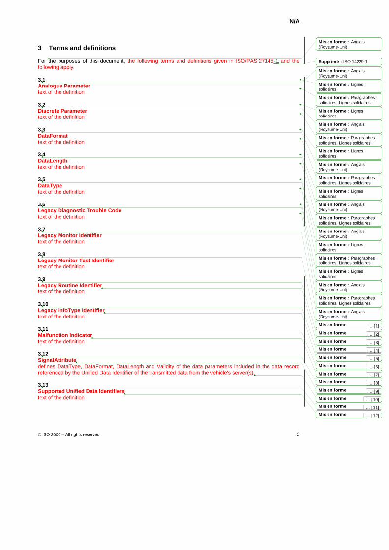
3 Terms and definitions
For the purposes of this document, the following terms and definitions in ISO 14229-1and the following applies.
3.1 CALID Calibration Identification is the identification code for a specific software/calibration contained in a server/ECU. If regulations require calibration identifications for emission-related software, those shall be reported in a standardised format as specified in Part 2.
3.2 Class A, B1, B2, C malfunctions These definitions apply to emissions-related OBD systems. Class A, B1, B2 or C are attributes of a DTC. These attributes characterise the impact of a malfunction on emissions or on the OBD system's monitoring capability according to the requirements of the WWH-OBD GTR.
3.3 Continuous-MI "Continuous-MI" means the malfunction indicator showing a steady indication at all times while the key is in the on (run) position with the engine running [ignition ON – engine ON].
3.4 Continuous-MI counter A Continuous-MI counter conveys the amount of time during which the OBD system has been operated while a Continuous-MI is activated.
3.5 CVN Calibration Verification Number is the server/ECU calculated verification number of a calibration identification number to verify the integrity of the software/calibration contained in a server/ECU. If regulations require calibration identifications for emission-related software, those shall be reported in a standardised format as specified in Part 2.
3.6 Discriminatory display This definition applies to emissions-related OBD systems. The discriminatory display strategy requires the MI to be activated according to the class in which a malfunction has been classified.
3.7 Malfunction Malfunction means a failure or deterioration of a vehicle or engine system or component, including the OBD system. The WWH-OBD GTR will specifically identify what conditions are considered to be malfunctions.
3.8 MI Malfunction Indicator is an indicator which clearly informs the driver of the vehicle in the event of a malfunction. Additional detail is included in the WWH-OBD GTR.
3.9 MI Counter A Malfunction Indicator counter conveys the amount of time during which the OBD system has operated while a malfunction is active.
3.10 Non – Discriminatory display This definition applies to emissions-related OBD systems. The non-discriminatory display strategy requires only a single type of MI activation.
ISO/PDPAS 27145-1.4
© ISO 2006 – All rights reserved 3
3.11 OBD A system that monitors some or all computer input and control signals. Signal(s) outside of the predetermined limits imply a fault in the system or in a related system.
3.12 Vehicle Identification Number The Vehicle Identification Number is the identification number specific and unique to each vehicle following the applicable legal provisions of each national/regional authority.
3.13 Vehicle On-Board Diagnostics The Vehicle On-Board Diagnostics provides a single access point for external test equipment to retrieve all data of the OBD system.
3.14 WWH-OBD GTR or GTR World Wide Harmonized On-Board Diagnostics Global Technical Regulation.
4 Symbols and abbreviated terms
CALID Calibration Identification
CVN Calibration Verification Number
DTC Diagnostic Trouble Code
DID Diagnostic Data Identifier
ECM Engine control module
ECU Electronic Control Unit
GTR Global Technical Regulations
MI Malfunction Indicator
VIN Vehicle Identification Number
VOBD Vehicle On-Board Diagnostics
WLAN Wireless Local Area Network
WWH-OBD Word Wide Harmonized On-Board Diagnostics
5 Conventions
ISO/PAS 27145 is based on the conventions discussed in the O.S.I. Service Conventions (ISO/IEC 10731:1994) as they apply for diagnostic services.
ISO/PDPAS 27145-1.4
4 © ISO 2006 – All rights reserved
6 Document overview
The ISO/PAS 27145 document set provides an implementer with all documents and references required to support the implementation of legislated on board diagnostics in accordance with the requirements set forth in GTR (Global Technical Regulation).
ISO/PAS 27145 – 1: General information and use case definitions (this part), provides an overview of the document set along with the use case definitions and a common set of resources (definitions, references) for use by all subsequent parts.
ISO/PAS 27145 – 2: Common emissions-related data dictionary, provides data definitions for emissions-related legislated diagnostics (see also Note below).
ISO/PAS 27145 – 3: Common message dictionary, provides the message implementation details from ISO 14229 – UDS to support the required legislated OBD.
ISO/PAS 27145 – 4: Connection between vehicle and test equipment, defines the details necessary to implement the communication between the vehicle's OBD systems and test equipment including the definition/reference of physical layers, data link layers, network layer, transport layer and session layer. This part of the standard will be extended as necessary due to introduction of additional communication media.
ISO/PAS 27145 – 5: External test equipment, provides the requirements according to the use cases defined in part 1 of this standard and how to establish, maintain, perform and terminate communication with the vehicle from the external test equipment point of view.
NOTE Additional parts of this standard will be introduced as necessary to consider further OBD systems not yet covered by this standard.
ISO/PDPAS 27145-1.4
© ISO 2006 – All rights reserved 5
7 Use case description
7.1 Overview
The OBD system is required to make available vehicle diagnostic information under several different use cases as specified by the GTR (Global Technical Regulation). These use cases provide the implementer with guidance in the implementation of the VOBD (described later in this document), and methodology used on the vehicle to make the required data available. This part of the standard will be extended as necessary due to introduction of additional WWH-OBD GTR use cases (i.e. non emissions-related).
7.2 Emissions-related use cases
7.2.1 Use case summary
The following is a summary of the use cases applicable to emissions-related OBD systems:
Use case 1: Information about the emissions-related OBD system state – The purpose of this information package is to provide the minimum data set specified as necessary by the WWH-OBD GTR to obtain the vehicle, or engine state with respect to its emission performance as specified in the GTR. A typical use of this information package may be a ‘Roadside Check’ performed by an enforcement authority.
Use case 2: Information about active emission-related malfunctions – The purpose of this information package is to provide access to the expanded data set specified as necessary by the WWH-OBD GTR to determine vehicle readiness and characterise the malfunctions detected by the OBD system. A typical use of this information package may be a periodic inspection by enforcement authorities.
Use case 3: Information related to diagnosis for the purpose of repair – The purpose of this information package is to provide access to all OBD data required by the WWH-OBD GTR and available from the OBD system. A typical use of this information package may be the Diagnostic Servicing of the vehicle or system in a workshop environment.
Detailed definition of each data item listed in the use cases can be found in the emissions-related module of the WWH-OBD GTR.
7.2.2 Use case 1 – Information about the emissions-related OBD system state
This use case provides an enforcement agency with the Malfunction Indication status and associated vehicle system data (e.g. MI counter, readiness status etc.).
The OBD system shall provide the data items as required by the emissions-related module of the WWH-OBD GTR and in the format as specified in ISO/PAS 27145–2 for the external roadside check test equipment to assimilate and provide the enforcement agency with the following information.
a) The GTR (and revision) number.
b) Discriminatory / Non-Discriminatory display strategy.
c) The VIN (Vehicle Identification Number).
d) Presence of a Continuous-MI.
e) The readiness status of the OBD system.
f) The number of engine operating hours during which a Continuous-MI was last activated (Continuous-MI counter).
This information shall be read-only access (i.e. no clearing) within the context of use case 1.
ISO/PDPAS 27145-1.4
6 © ISO 2006 – All rights reserved
7.2.3 Use case 2 – Information about active and confirmed emission-related malfunctions
This information will provide any inspection station with a subset of engine related OBD data including the Malfunction Indicator status and associated data (MI counters), a list of active/confirmed malfunctions of classes A and B and associated data (e.g. B1-counter).
The OBD system shall provide the data items as required by the emissions-related module of the WWH-OBD GTR and in the format as specified in ISO/PAS 27145–2 for the external inspection test equipment to assimilate the data and provide an inspector with the following information:
a) The GTR (and revision) number.
b) Discriminatory/non-discriminatory display strategy.
c) The VIN (Vehicle Identification Number).
d) The Malfunction Indicator status.
e) The Readiness status of the OBD system.
f) The number of engine operating hours since the Malfunction Indicator has been activated (Continuous-MI counter).
g) The cumulated operating hours with a Continuous-MI (cumulative Continuous-MI counter).
h) The confirmed and active DTCs for Class A malfunctions.
i) The confirmed and active DTCs for Classes B (B1 and B2) malfunctions.
j) The confirmed and active DTCs Class B1 malfunctions.
This information shall be read only access (i.e. no clearing) within the context of use case 2.
7.2.4 Use case 3 – Information related to diagnosis for the purpose of repair
This information will provide repair technicians with all OBD data specified in the GTR (e.g. Freeze Frame information).
The OBD system shall provide the data items as required by the emissions-related module of the WWH-OBD GTR and in the format as specified in ISO/PAS 27145–2 for the external repair test equipment to assimilate the data and provide a repair technician with the following information:
a) The GTR (and revision) number.
b) The VIN (Vehicle Identification Number).
c) The Malfunction Indicator status.
d) The Readiness status of the OBD system.
e) The number of engine operating hours since the Malfunction Indicator has been activated (Continuous-MI counter).
f) The confirmed and active DTCs for Class A malfunctions.
g) The confirmed and active DTCs for Classes B (B1 and B2) malfunctions.
h) The confirmed and active DTCs for Class B1 malfunctions and the number of engine operating hours from the B1 counters.
ISO/PDPAS 27145-1.4
© ISO 2006 – All rights reserved 7
i) The confirmed and active DTCs for Class C malfunctions.
j) The pending DTCs and their associated class.
k) The previously active DTCs and their associated class.
l) Real-time information on OEM selected and supported sensor signals, internal parameters and output signals.
m) The freeze frame data.
n) The software CALID(s) (calibration identification(s)).
o) The CVN(s) (calibration verification number(s)).
The OBD system shall clear all the recorded information related to malfunctions of the engine system and related data (operating time information, freeze frame, etc.) in accordance with the provisions of the WWH-OBD GTR, when this request is provided via the external repair test equipment according to ISO/PAS 27145–2.
8 Vehicle On-Board Diagnostic (VOBD)
8.1 VOBD definition
The following specifies general VOBD information including but not limited to minimum functionality, system data storage, and application examples. The information provided in this standard should be used as a reference framework for VOBD system implementers.
The VOBD consists of:
The "VOBD system" which consists of the individual OBD system(s) (e.g. ECUs),
A "single VOBD access method" as required by the WWH-OBD GTR to provide access to the VOBD data set and all other diagnostic functions,
The "VOBD data set" which is defined as a limited set of data provided by the OBD systems to fulfil the requirements of the various use cases as defined in the WWH-OBD GTR.
The VOBD will always support the same request and response behaviour when communicating with the external test equipment.
8.2 VOBD system
The VOBD system shall be implemented in the vehicle's electrical architecture and shall meet the communication performance requirements as specified in the WWH-OBD GTR.
The VOBD system provides the flexibility for the extension of the use of the ISO/PAS 27145 document set (e.g. add the wireless access to emissions-related OBD data defined in use case 1 in the future).
One of the ECU(s) of the VOBD system may act as a Gateway between the external test equipment and the other ECU(s) of the VOBD system in case the O.S.I. layers 1 through 4 of the in-vehicle network are different from those defined within this document.
The VOBD system may be (a) dedicated ECU(s), or be provided by another vehicle ECU or system. It is possible, that the VOBD functionality may exist as a ‘Software only’ module in a vehicle system. The VOBD system provides the flexibility to support not only emissions-related OBD systems but also other legislated vehicle systems that may or may not be under consideration today.
ISO/PDPAS 27145-1.4
8 © ISO 2006 – All rights reserved
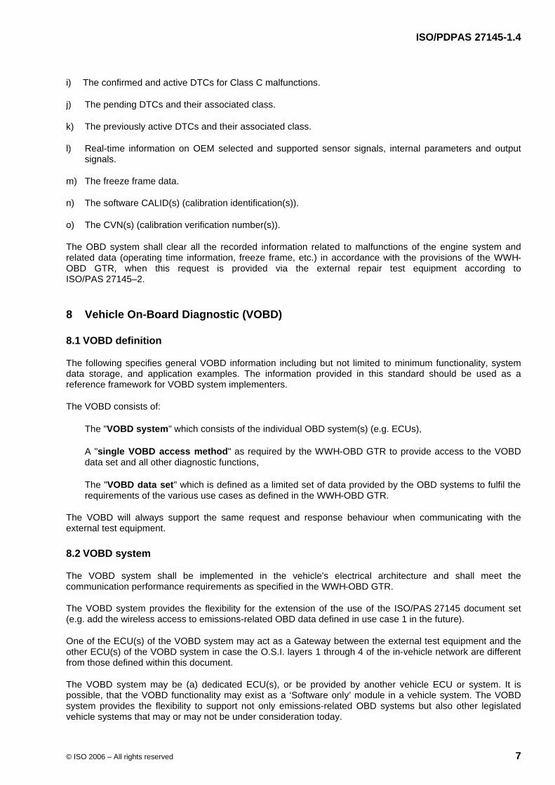
The following are examples for the implementation of the VOBD system in the vehicle's network.
Figure 1 shows an implementation example of the VOBD system in a Gateway ECU and the Engine ECU (ECU 1). The Gateway ECU is not part of the e.g. emissions-related OBD system.
Key
1 Connection according to ISO/PAS 27145–4
Figure 1 — Implementation example of VOBD in a Gateway ECU and Engine ECU
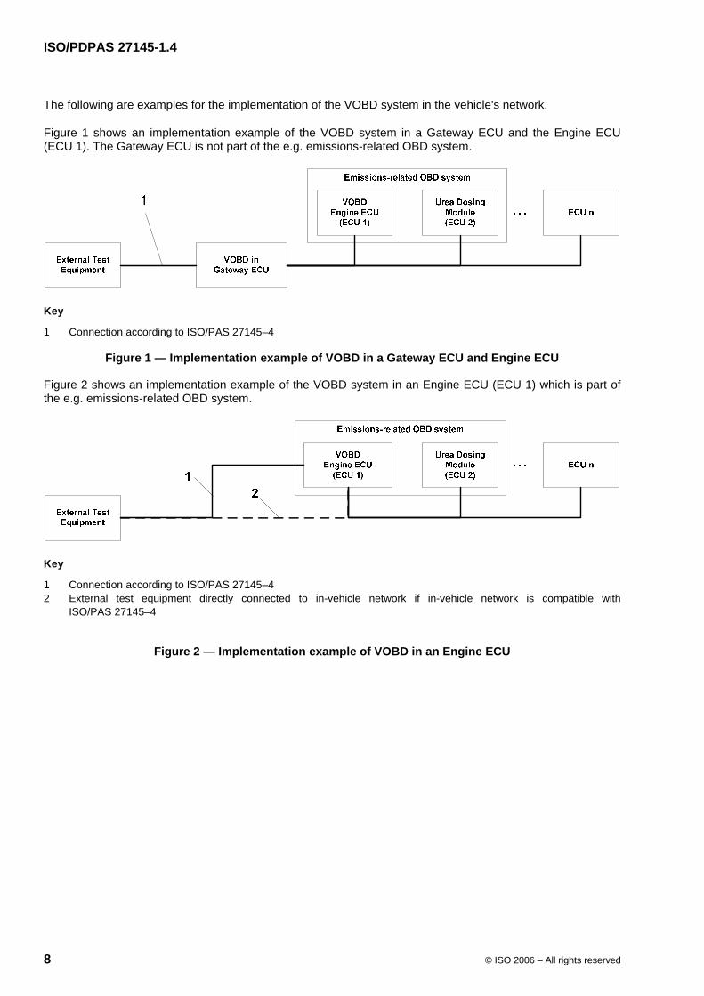
Figure 2 shows an implementation example of the VOBD system in an Engine ECU (ECU 1) which is part of the e.g. emissions-related OBD system.
Key
1 Connection according to ISO/PAS 27145–4 2 External test equipment directly connected to in-vehicle network if in-vehicle network is compatible with
ISO/PAS 27145–4
Figure 2 — Implementation example of VOBD in an Engine ECU
ISO/PDPAS 27145-1.4
© ISO 2006 – All rights reserved 9
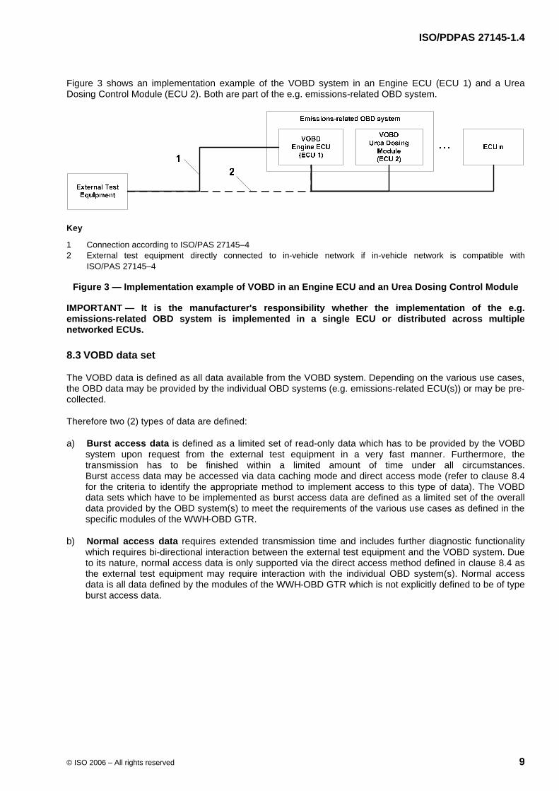
Figure 3 shows an implementation example of the VOBD system in an Engine ECU (ECU 1) and a Urea Dosing Control Module (ECU 2). Both are part of the e.g. emissions-related OBD system.
Key
1 Connection according to ISO/PAS 27145–4 2 External test equipment directly connected to in-vehicle network if in-vehicle network is compatible with
ISO/PAS 27145–4
Figure 3 — Implementation example of VOBD in an Engine ECU and an Urea Dosing Control Module
IMPORTANT — It is the manufacturer's responsibility whether the implementation of the e.g. emissions-related OBD system is implemented in a single ECU or distributed across multiple networked ECUs.
8.3 VOBD data set
The VOBD data is defined as all data available from the VOBD system. Depending on the various use cases, the OBD data may be provided by the individual OBD systems (e.g. emissions-related ECU(s)) or may be pre-collected.
Therefore two (2) types of data are defined:
a) Burst access data is defined as a limited set of read-only data which has to be provided by the VOBD system upon request from the external test equipment in a very fast manner. Furthermore, the transmission has to be finished within a limited amount of time under all circumstances. Burst access data may be accessed via data caching mode and direct access mode (refer to clause 8.4 for the criteria to identify the appropriate method to implement access to this type of data). The VOBD data sets which have to be implemented as burst access data are defined as a limited set of the overall data provided by the OBD system(s) to meet the requirements of the various use cases as defined in the specific modules of the WWH-OBD GTR.
b) Normal access data requires extended transmission time and includes further diagnostic functionality which requires bi-directional interaction between the external test equipment and the VOBD system. Due to its nature, normal access data is only supported via the direct access method defined in clause 8.4 as the external test equipment may require interaction with the individual OBD system(s). Normal access data is all data defined by the modules of the WWH-OBD GTR which is not explicitly defined to be of type burst access data.
ISO/PDPAS 27145-1.4
10 © ISO 2006 – All rights reserved
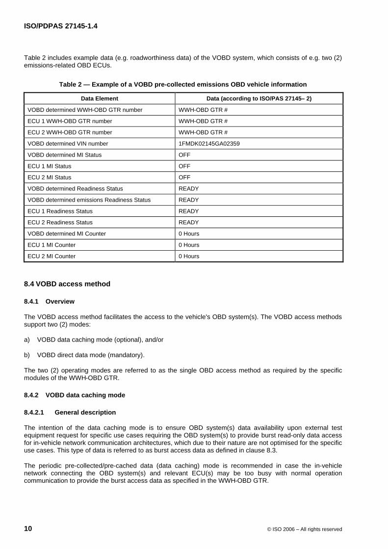
Table 2 includes example data (e.g. roadworthiness data) of the VOBD system, which consists of e.g. two (2) emissions-related OBD ECUs.
Table 2 — Example of a VOBD pre-collected emissions OBD vehicle information
Data Element Data (according to ISO/PAS 27145– 2)
VOBD determined WWH-OBD GTR number WWH-OBD GTR #
ECU 1 WWH-OBD GTR number WWH-OBD GTR #
ECU 2 WWH-OBD GTR number WWH-OBD GTR #
VOBD determined VIN number 1FMDK02145GA02359
VOBD determined MI Status OFF
ECU 1 MI Status OFF
ECU 2 MI Status OFF
VOBD determined Readiness Status READY
VOBD determined emissions Readiness Status READY
ECU 1 Readiness Status READY
ECU 2 Readiness Status READY
VOBD determined MI Counter 0 Hours
ECU 1 MI Counter 0 Hours
ECU 2 MI Counter 0 Hours
8.4 VOBD access method
8.4.1 Overview
The VOBD access method facilitates the access to the vehicle's OBD system(s). The VOBD access methods support two (2) modes:
a) VOBD data caching mode (optional), and/or
b) VOBD direct data mode (mandatory).
The two (2) operating modes are referred to as the single OBD access method as required by the specific modules of the WWH-OBD GTR.
8.4.2 VOBD data caching mode
8.4.2.1 General description
The intention of the data caching mode is to ensure OBD system(s) data availability upon external test equipment request for specific use cases requiring the OBD system(s) to provide burst read-only data access for in-vehicle network communication architectures, which due to their nature are not optimised for the specific use cases. This type of data is referred to as burst access data as defined in clause 8.3.
The periodic pre-collected/pre-cached data (data caching) mode is recommended in case the in-vehicle network connecting the OBD system(s) and relevant ECU(s) may be too busy with normal operation communication to provide the burst access data as specified in the WWH-OBD GTR.
ISO/PDPAS 27145-1.4
© ISO 2006 – All rights reserved 11
In this mode the data cache of the VOBD acts as the source of information defined by those use cases, which require the OBD system(s) to make burst access data available upon the external test equipment's request. The VOBD system continuously caches information from the relevant OBD system(s). This information is then available for e.g. inspection by external inspection test equipment.
The information requested by the external test equipment depends on the specific use cases as specified by the specific modules of the WWH-OBD GTR. Each use case requires a set of data supported by the individual OBD system(s).
IMPORTANT — It is the manufacturer's responsibility to determine the necessity of the implementation of VOBD data caching mode to support the burst data access in order to comply with the WWH-OBD GTR communication performance requirements.
8.4.2.2 VOBD data caching sampling period definition
The maximum age of each data item is defined in ISO/PAS 27145–2 Common emissions-related data dictionary in compliance with the requirements of the WWH-OBD GTR, which will be referred to as maximum data age. In case additional modules of the WWH-OBD GTR are legislated the ISO/PAS 27145 set of documents will be extended accordingly.
IMPORTANT — The maximum data age is different from the communication timing requirements associated with burst access data and normal access data.
EXAMPLE A specific data item may be required not to be older than 10 seconds but may be required to be implemented as burst access data.
8.4.2.3 VOBD caching mode implementation
This section describes the implementation of the VOBD data caching mode. The Gateway ECU utilises the same diagnostic services as the external test equipment would use in direct data mode to cache read-only data from the e.g. emissions-related OBD system ECU(s). Alternatively the Gateway ECU may retrieve the requested information via normal communication on the vehicle's network.
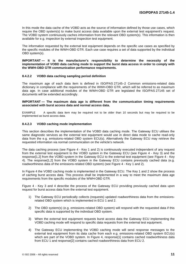
The data caching process (see Figure 4 - Key 1 and 2) is continuously executed independent of any request from the external test equipment to the VOBD system in the Gateway ECU (see Figure 4 - Key 3) and the response[1,2] from the VOBD system in the Gateway ECU to the external test equipment (see Figure 4 - Key 4). The response[1,2] from the VOBD system in the Gateway ECU contains previously cached data (e.g. roadworthiness data of the emissions-related OBD system) (see Figure 4 - Key 1 and 2).
In Figure 4 the VOBD caching mode is implemented in the Gateway ECU. The Key 1 and 2 show the process of caching burst access data. This process shall be implemented in a way to meet the maximum data age requirements from the specific modules of the WWH-OBD GTR.
Figure 4 - Key 3 and 4 describe the process of the Gateway ECU providing previously cached data upon request for burst access data from the external test equipment.
1) The Gateway ECU periodically collects (requests) updated roadworthiness data from the emissions-related OBD system which is implemented in ECU 1 and 2.
2) The OBD system(s) (e.g. emissions-related OBD system) will respond with the requested data if this specific data is supported by the individual OBD system.
3) When the external test equipment requests burst access data the Gateway ECU implementing the VOBD caching mode will respond to specific data requests from the external test equipment.
4) The Gateway ECU implementing the VOBD caching mode will send response messages to the external test equipment from its data cache from each e.g. emissions-related OBD system ECU(s) which are part of the VOBD system. In Figure 4, response[1] contains cached roadworthiness data from ECU 1 and response[2] contains cached roadworthiness data from ECU 2.
ISO/PDPAS 27145-1.4
12 © ISO 2006 – All rights reserved
Key
1 Request from Gateway ECU to emissions-related OBD system ECUs to cache burst access data 2 Gateway ECU collects response[1] from Engine ECU and response[2] from Urea Dosing Control Module 3 Request from external test equipment to the VOBD system to retrieve emissions-related burst access data 4 Response[1,2] from VOBD system in the Gateway ECU containing the cached data (e.g. roadworthiness data) of the
emissions-related OBD system.
Figure 4 — VOBD caching methodology of roadworthiness data in a Gateway ECU
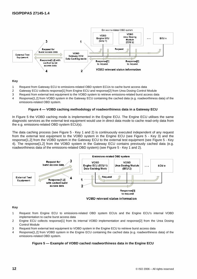
In Figure 5 the VOBD caching mode is implemented in the Engine ECU. The Engine ECU utilises the same diagnostic services as the external test equipment would use in direct data mode to cache read-only data from the e.g. emissions-related OBD system ECU(s).
The data caching process (see Figure 5 - Key 1 and 2) is continuously executed independent of any request from the external test equipment to the VOBD system in the Engine ECU (see Figure 5 - Key 3) and the response[1,2] from the VOBD system in the Gateway ECU to the external test equipment (see Figure 5 - Key 4). The response[1,2] from the VOBD system in the Gateway ECU contains previously cached data (e.g. roadworthiness data of the emissions-related OBD system) (see Figure 5 - Key 1 and 2).
Key
1 Request from Engine ECU to emissions-related OBD system ECUs and the Engine ECU’s internal VOBD implementation to cache burst access data
2 Engine ECU collects response[1] from its internal VOBD implementation and response[2] from the Urea Dosing Control Module
3 Request from external test equipment to VOBD system in the Engine ECU to retrieve burst access data 4 Response[1,2] from VOBD system in the Engine ECU containing the cached data (e.g. roadworthiness data) of the
emissions-related OBD system.
Figure 5 — Example of VOBD cached roadworthiness data in the Engine ECU
ISO/PDPAS 27145-1.4
© ISO 2006 – All rights reserved 13
8.4.3 VOBD direct data mode
8.4.3.1 General description
The pass-through data (direct data) mode is recommended in case the in-vehicle network connecting the OBD system(s) and relevant ECU(s) meet the communication performance requirements of the specific module of the WWH-OBD GTR. This mode of operation is recommended for the burst data access, if the OBD system and vehicle network performance is sufficient to comply with the WWH-OBD GTR communication performance requirements. It is recommended that this choice should minimise the impact of possible future evolutions e.g. new OBD systems required by specific modules of the WWH-OBD GTR.
In this mode the VOBD system is in a pass-through (direct data) mode of operation and acts as a message header converter in case the data link between the external test equipment and the ECU(s), containing the VOBD system, is different.
8.4.3.2 VOBD direct data mode implementation
The external test equipment requests VOBD emissions-related OBD system status information (e.g. roadworthiness data) from the VOBD.
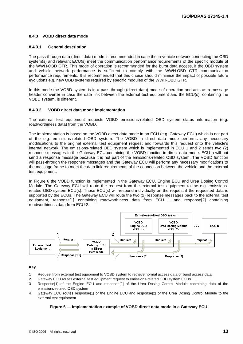
The implementation is based on the VOBD direct data mode in an ECU (e.g. Gateway ECU) which is not part of the e.g. emissions-related OBD system. The VOBD in direct data mode performs any necessary modifications to the original external test equipment request and forwards this request onto the vehicle's internal network. The emissions-related OBD system which is implemented in ECU 1 and 2 sends two (2) response messages to the Gateway ECU containing the VOBD function in direct data mode. ECU n will not send a response message because it is not part of the emissions-related OBD system. The VOBD function will pass-through the response messages and the Gateway ECU will perform any necessary modifications to the message frame to meet the data link requirements of the connection between the vehicle and the external test equipment.
In Figure 6 the VOBD function is implemented in the Gateway ECU, Engine ECU and Urea Dosing Control Module. The Gateway ECU will route the request from the external test equipment to the e.g. emissions-related OBD system ECU(s). Those ECU(s) will respond individually on the request if the requested data is supported by the ECUs. The Gateway ECU will route the two (2) response messages back to the external test equipment, response[1] containing roadworthiness data from ECU 1 and response[2] containing roadworthiness data from ECU 2.
Key
1 Request from external test equipment to VOBD system to retrieve normal access data or burst access data 2 Gateway ECU routes external test equipment request to emissions-related OBD system ECUs 3 Response[1] of the Engine ECU and response[2] of the Urea Dosing Control Module containing data of the
emissions-related OBD system 4 Gateway ECU routes response[1] of the Engine ECU and response[2] of the Urea Dosing Control Module to the
external test equipment
Figure 6 — Implementation example of VOBD direct data mode in a Gateway ECU
ISO/PDPAS 27145-1.4
14 © ISO 2006 – All rights reserved
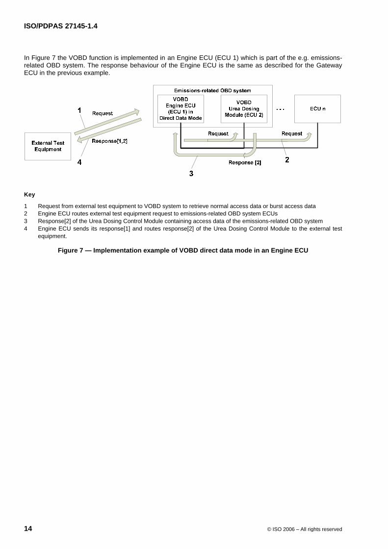
In Figure 7 the VOBD function is implemented in an Engine ECU (ECU 1) which is part of the e.g. emissions-related OBD system. The response behaviour of the Engine ECU is the same as described for the Gateway ECU in the previous example.
Key
1 Request from external test equipment to VOBD system to retrieve normal access data or burst access data 2 Engine ECU routes external test equipment request to emissions-related OBD system ECUs 3 Response[2] of the Urea Dosing Control Module containing access data of the emissions-related OBD system 4 Engine ECU sends its response[1] and routes response[2] of the Urea Dosing Control Module to the external test
equipment.
Figure 7 — Implementation example of VOBD direct data mode in an Engine ECU
© ISO 2006 – All rights reserved
Document type: Publicly Available Specification Document subtype: Document stage: (30) Committee Document language: E C:\WWH-obd\GENEVA 2006_06\prepa meeting\ISO_PAS_27145-2.8_(E)_WWH-OBD_CDD-Emissions_2006-05-29.doc STD Version 2.1c2
ISO TC 22/SC 3 N Date: 2006-05-29
N/A
ISO TC 22/SC 3/WG 1
Secretariat: DIN
Road vehicles — Implementation of WWH-OBD communication requirements — Part 2: Common emissions-related data dictionary
Élément introductif — Élément central — Partie 2: Titre de la partie
Warning
This document is not an ISO International Standard. It is distributed for review and comment. It is subject to change without notice and may not be referred to as an International Standard.
Recipients of this draft are invited to submit, with their comments, notification of any relevant patent rights of which they are aware and to provide supporting documentation.
Mis en forme : Anglais(Royaume-Uni)
Mis en forme : Anglais(Royaume-Uni)
Mis en forme : Anglais(Royaume-Uni)
Mis en forme : Anglais(Royaume-Uni)
Mis en forme : Anglais(Royaume-Uni)
Mis en forme : Anglais(Royaume-Uni)
Mis en forme : Anglais(Royaume-Uni)
Mis en forme : Anglais(Royaume-Uni)
Mis en forme : Anglais(Royaume-Uni)
Mis en forme : Anglais(Royaume-Uni)
Mis en forme : Anglais(Royaume-Uni)
Mis en forme : Anglais(Royaume-Uni)
Mis en forme : Anglais(Royaume-Uni)
Mis en forme : Anglais(Royaume-Uni)
Mis en forme : Anglais(Royaume-Uni)
Mis en forme : Anglais(Royaume-Uni)
N/A
ii © ISO 2006 – All rights reserved
Copyright notice
This ISO document is a working draft or committee draft and is copyright-protected by ISO. While the reproduction of working drafts or committee drafts in any form for use by participants in the ISO standards development process is permitted without prior permission from ISO, neither this document nor any extract from it may be reproduced, stored or transmitted in any form for any other purpose without prior written permission from ISO.
Requests for permission to reproduce this document for the purpose of selling it should be addressed as shown below or to ISO's member body in the country of the requester:
[Indicate the full address, telephone number, fax number, telex number, and electronic mail address, as appropriate, of the Copyright Manger of the ISO member body responsible for the secretariat of the TC or SC within the framework of which the working document has been prepared.]
Reproduction for sales purposes may be subject to royalty payments or a licensing agreement.
Violators may be prosecuted.
N/A
© ISO 2006 – All rights reserved iii
Contents Page
Foreword ............................................................................................................................................................ iv Introduction........................................................................................................................................................ iv 1 Scope ......................................................................................................................................................4 2 Normative references............................................................................................................................4 3 Terms and definitions ...........................................................................................................................4 4 Symbols and abbreviated terms ..........................................................................................................4 5 Conventions...........................................................................................................................................4 6 Common data dictionary ......................................................................................................................4 7 Data identifier and data record requirements.....................................................................................4 7.1 Legacy data identifiers..........................................................................................................................4 7.1.1 ISO 15031-5:2006 and ISO 14229-1:2006 legacy DID definition........................................................4 7.1.2 Legacy ISO 15031-5:2006 identifier supported definition .................................................................4 7.1.3 Legacy data record definition ..............................................................................................................4 7.1.4 Overview.................................................................................................................................................4 7.1.5 Legacy PID data record structure ........................................................................................................4 7.1.6 Legacy MID data record structure .......................................................................................................4 7.1.7 Legacy InfoType ID data record structure ..........................................................................................4 7.1.8 Legacy RID data record structure........................................................................................................4 7.1.9 SAE J1939 legacy data identifier definition ........................................................................................4 7.2 Unified data identifiers..........................................................................................................................4 7.2.1 Unified data identifier range layout .....................................................................................................4 7.2.2 Unified data identifier supported definition........................................................................................4 7.3 Manufacturer data identifier .................................................................................................................4 7.3.1 Manufacturer data identifier range layout...........................................................................................4 7.3.2 Manufacturer data parameter requirements .......................................................................................4 7.4 Unified data record definition ..............................................................................................................4 7.4.1 Overview.................................................................................................................................................4 7.4.2 Remotely received sub-node information and validity......................................................................4 7.4.3 SignalAttribute (SA) A1 and A2 definition ..........................................................................................4 7.4.4 Supported data types............................................................................................................................4 7.4.5 Unified PID data record structure ........................................................................................................4 7.4.6 Unified MID data record structure .......................................................................................................4 7.4.7 Unified InfoType ID data record structure ..........................................................................................4 7.4.8 Unified RID data record structure........................................................................................................4 8 Diagnostic Trouble Code definition.....................................................................................................4 8.1 Overview.................................................................................................................................................4 8.2 Legacy DTCs..........................................................................................................................................4 8.2.1 ISO 15031 legacy DTC to unified DTC mapping .................................................................................4 8.2.2 ISO 15031-6:2005 legacy DTC encoding .............................................................................................4 8.2.3 SAE J1939-73 legacy DTC to unified DTC mapping ..........................................................................4 8.2.4 SAE J1939-73 legacy DTC encoding ...................................................................................................4 8.3 Unified DTC ............................................................................................................................................4 8.3.1 Unified DTC range layout......................................................................................................................4 8.3.2 Unified DTC format................................................................................................................................4 8.3.3 Unified DTC encoding ...........................................................................................................................4 8.3.4 BaseDTC supported Unified PID data record structure ....................................................................4 8.4 Manufacturer DTC .................................................................................................................................4 8.4.1 Manufacturer DTC range layout...........................................................................................................4
Mis en forme : Anglais(Royaume-Uni)
N/A
iv © ISO 2006 – All rights reserved
8.4.2 Manufacturer DTC based on unified DTC format ...............................................................................4 8.4.3 Manufacturer DTC encoding.................................................................................................................4 Annex A (normative) Emissions-related Data Identifier supported definition..............................................4 Annex B (normative) Emissions-related Legacy PIDs (LPID).........................................................................4 B.1 Emissions-related LPID definition and scaling ..................................................................................4 B.2 Standard set of emissions-related LPIDs of DTC specific snapshot ...............................................4 Annex C (normative) Emissions-related Legacy Monitor TIDs (LMTID)........................................................4 C.1 Standardized OBD Monitor Test IDs....................................................................................................4 C.2 Manufacturer defined OBD Monitor Test IDs......................................................................................4 Annex D (normative) Emissions-related Legacy MIDs (LMID) .......................................................................4 Annex E (normative) Emissions-related Legacy Monitor Units and Scalings ..............................................4 E.1 Emissions-related Legacy Monitor Unit and Scaling definition .......................................................4 E.1.1 Unsigned Unit and Scaling Identifiers definition................................................................................4 E.1.2 Signed Unit and Scaling Identifiers definition ....................................................................................4 Annex F (normative) Emissions-related Legacy Routine Identifier (LRID) ...................................................4 F.1 Emissions-related LRID definition .......................................................................................................4 Annex G (normative) Emissions-related Legacy InfoType IDs (LITID) ..........................................................4 G.1 Emissions-related LITID definition and scaling..................................................................................4 Annex H (normative) Emissions-related DTCExtendedData record definition.............................................4 Annex I (normative) Emissions-related Unified Parameter Identifier (UPID) ................................................4 Annex J (normative) Emissions-related Legacy DTC (LDTC).........................................................................4 Annex K (normative) Legacy DTC Failure Type Byte (FTB)............................................................................4 Annex L (normative) Unified DTC definition (UDTC) .......................................................................................4 Annex M (normativ) Unified DTC Failure Type Byte (FTB) .............................................................................4
N/A
© ISO 2006 – All rights reserved v
Foreword
ISO (the International Organization for Standardization) is a worldwide federation of national standards bodies (ISO member bodies). The work of preparing International Standards is normally carried out through ISO technical committees. Each member body interested in a subject for which a technical committee has been established has the right to be represented on that committee. International organizations, governmental and non-governmental, in liaison with ISO, also take part in the work. ISO collaborates closely with the International Electrotechnical Commission (IEC) on all matters of electrotechnical standardization.
International Standards are drafted in accordance with the rules given in the ISO/IEC Directives, Part 2.
The main task of technical committees is to prepare International Standards. Draft International Standards adopted by the technical committees are circulated to the member bodies for voting. Publication as an International Standard requires approval by at least 75 % of the member bodies casting a vote.
In other circumstances, particularly when there is an urgent market requirement for such documents, a technical committee may decide to publish other types of normative document:
— an ISO Publicly Available Specification (ISO/PAS) represents an agreement between technical experts in an ISO working group and is accepted for publication if it is approved by more than 50 % of the members of the parent committee casting a vote;
— an ISO Technical Specification (ISO/TS) represents an agreement between the members of a technical committee and is accepted for publication if it is approved by 2/3 of the members of the committee casting a vote.
An ISO/PAS or ISO/TS is reviewed after three years in order to decide whether it will be confirmed for a further three years, revised to become an International Standard, or withdrawn. If the ISO/PAS or ISO/TS is confirmed, it is reviewed again after a further three years, at which time it must either be transformed into an International Standard or be withdrawn.
Attention is drawn to the possibility that some of the elements of this document may be the subject of patent rights. ISO shall not be held responsible for identifying any or all such patent rights.
ISO/PAS 27145-2 was prepared by Technical Committee ISO/TC 22, Road vehicles, Subcommittee SC 3, Electrical and electronic equipment.
ISO/PAS 27145 consists of the following parts, under the general title Road vehicles — Implementation of WWH-OBD communication requirements:
Part 1: General information and use case definition
Part 2: Common emissions-related data dictionary
Part 3: Common message dictionary
Part 4: Connection between vehicle and test equipment
Part 5: External test equipment
NOTE Part 4 of the standard will be extended as necessary due to introduction of additional communication media.
Mis en forme : Anglais(Royaume-Uni)
Mis en forme : Anglais(Royaume-Uni)
Supprimé : <#>Part 6: Conformance test
N/A
vi © ISO 2006 – All rights reserved
Introduction
This document set includes the communication between the vehicle's OBD systems and test equipment implemented across vehicles within the scope of the WWH-OBD GTR (World Wide Harmonized On-Board Diagnostics Global Technical Regulations).
It has been established in order to apply the unified diagnostic services (specified in ISO 14229-1:2006 Road vehicles – Unified diagnostic services (UDS) – Part 1: Specification and requirements) to WWH OBD systems.
To achieve this, it is based on the Open Systems Interconnection (OSI) Basic Reference Model in accordance with ISO/IEC 7498 and ISO/IEC 10731, which structures communication systems into seven layers. When mapped on this model, the services specified by ISO/PAS 27145 are broken into:
Application layer (layer 7), specified in ISO/PAS 27145-2,
Presentation layer (layer 6), specified in ISO/PAS 27145-3,
Session layer services (layer 5), specified in ISO/PAS 27145-4,
Transport layer services (layer 4), specified in ISO/PAS 27145-4,
Network layer services (layer 3), specified in ISO/PAS 27145-4,
Data link layer (layer 2), specified in ISO/PAS 27145-4,
Physical layer (layer 1), specified in ISO/PAS 27145-4,
in accordance with Table 1.
Table 1 — Enhanced and legislated OBD diagnostic specifications applicable to the O.S.I. layers
Applicability OSI 7 layers Implementation of WWH-OBD communication requirements e.g. Emissions-related UDS
Application (layer 7) ISO/PAS 27145-2 / ISO 14229-1:2006
Presentation (layer 6) ISO/PAS 27145-3
Session (layer 5)
Transport (layer 4)
Network (layer 3)
Data link (layer 2)
Seven layer according to
ISO/IEC 7498 and ISO/IEC 10731
Physical (layer 1)
ISO/PAS 27145-4
Mis en forme : Anglais (Royaume-Uni)
Mis en forme : Anglais (Royaume-Uni)
Mis en forme : Anglais (Royaume-Uni)
Mis en forme : Anglais (Royaume-Uni)
Mis en forme : Anglais (Royaume-Uni)
Mis en forme : Anglais (Royaume-Uni)
Mis en forme : Anglais (Royaume-Uni)
Mis en forme : Anglais (Royaume-Uni)
Mis en forme : Anglais (Royaume-Uni)
Mis en forme : Anglais (Royaume-Uni)
Mis en forme : Anglais (Royaume-Uni)
Mis en forme : Anglais (Royaume-Uni)
Mis en forme : Anglais (Royaume-Uni)
Mis en forme : Anglais (Royaume-Uni)
Mis en forme : Anglais (Royaume-Uni)
Mis en forme : Anglais (Royaume-Uni)
Supprimé : ISO 14229-2
Supprimé : (CAN, Ethernet, optional WLAN)
N/A
© ISO 2006 – All rights reserved 1
Road vehicles — Implementation of WWH-OBD communication requirements — Part 2: Common emissions-related data dictionary
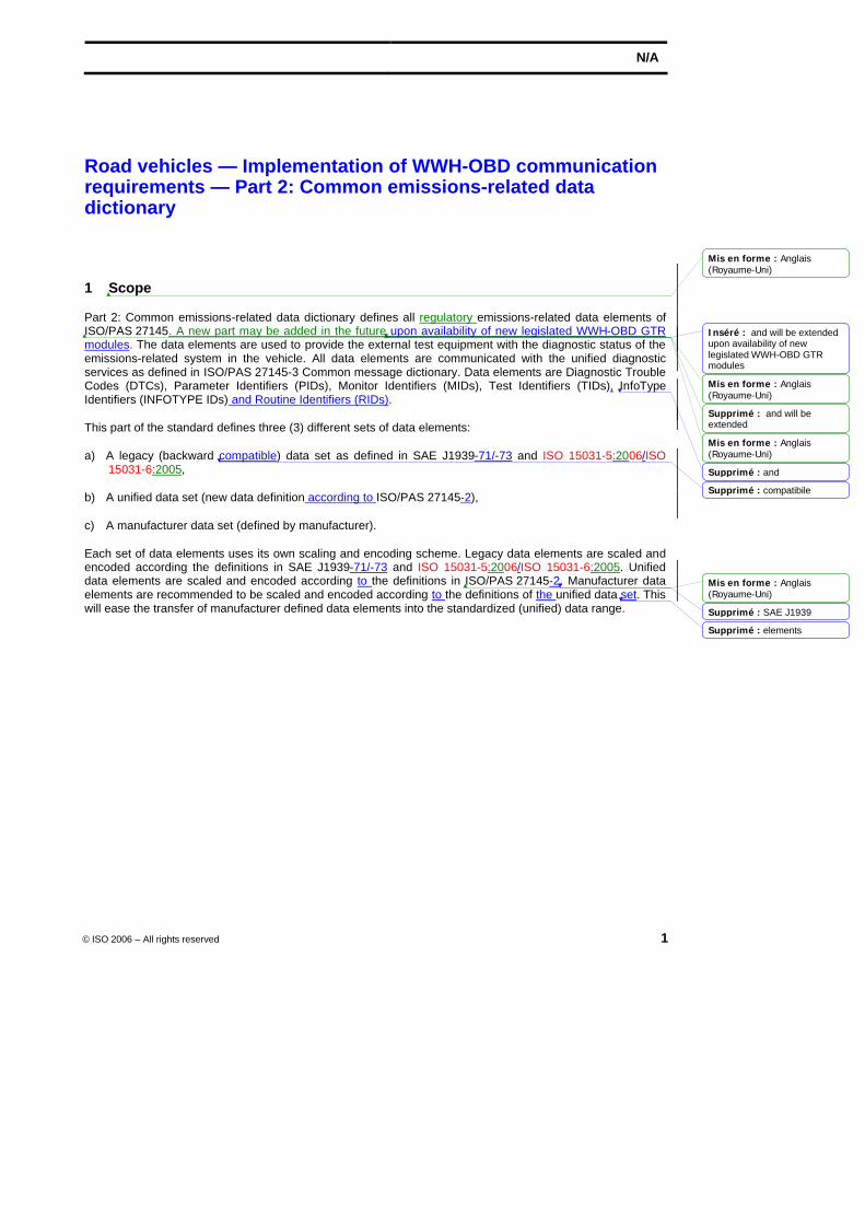
1 Scope
Part 2: Common emissions-related data dictionary defines all regulatory emissions-related data elements of ISO/PAS 27145. A new part may be added in the future upon availability of new legislated WWH-OBD GTR modules. The data elements are used to provide the external test equipment with the diagnostic status of the emissions-related system in the vehicle. All data elements are communicated with the unified diagnostic services as defined in ISO/PAS 27145-3 Common message dictionary. Data elements are Diagnostic Trouble Codes (DTCs), Parameter Identifiers (PIDs), Monitor Identifiers (MIDs), Test Identifiers (TIDs), InfoType Identifiers (INFOTYPE IDs) and Routine Identifiers (RIDs).
This part of the standard defines three (3) different sets of data elements:
a) A legacy (backward compatible) data set as defined in SAE J1939-71/-73 and ISO 15031-5:2006/ISO 15031-6:2005,
b) A unified data set (new data definition according to ISO/PAS 27145-2),
c) A manufacturer data set (defined by manufacturer).
Each set of data elements uses its own scaling and encoding scheme. Legacy data elements are scaled and encoded according the definitions in SAE J1939-71/-73 and ISO 15031-5:2006/ISO 15031-6:2005. Unified data elements are scaled and encoded according to the definitions in ISO/PAS 27145-2. Manufacturer data elements are recommended to be scaled and encoded according to the definitions of the unified data set. This will ease the transfer of manufacturer defined data elements into the standardized (unified) data range.
Mis en forme : Anglais(Royaume-Uni)
Mis en forme : Anglais(Royaume-Uni)
Mis en forme : Anglais(Royaume-Uni)
Mis en forme : Anglais(Royaume-Uni)
Inséré : and will be extended upon availability of new legislated WWH-OBD GTR modules
Supprimé : and will be extended
Supprimé : and
Supprimé : compatibile
Supprimé : SAE J1939
Supprimé : elements
N/A
2 © ISO 2006 – All rights reserved
2 Normative references
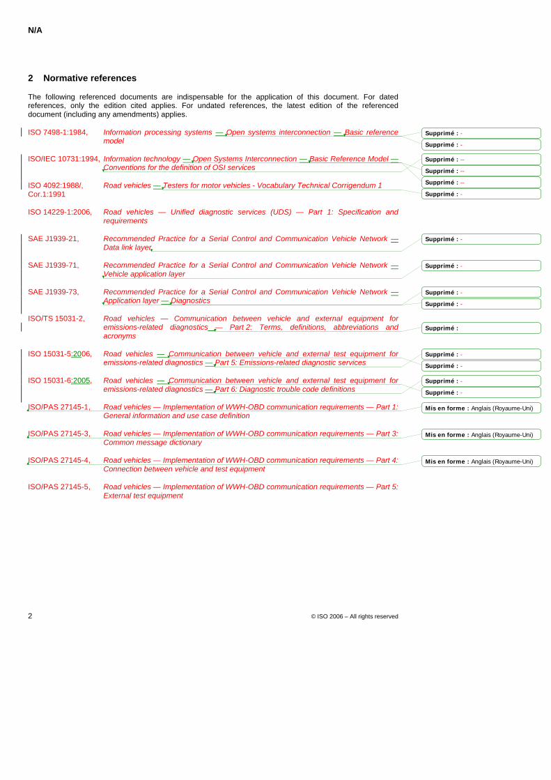
The following referenced documents are indispensable for the application of this document. For dated references, only the edition cited applies. For undated references, the latest edition of the referenced document (including any amendments) applies.
ISO 7498-1:1984, Information processing systems — Open systems interconnection — Basic reference model
ISO/IEC 10731:1994, Information technology — Open Systems Interconnection — Basic Reference Model — Conventions for the definition of OSI services
ISO 4092:1988/, Road vehicles — Testers for motor vehicles - Vocabulary Technical Corrigendum 1 Cor.1:1991
ISO 14229-1:2006, Road vehicles — Unified diagnostic services (UDS) — Part 1: Specification and requirements
SAE J1939-21, Recommended Practice for a Serial Control and Communication Vehicle Network — Data link layer
SAE J1939-71, Recommended Practice for a Serial Control and Communication Vehicle Network — Vehicle application layer
SAE J1939-73, Recommended Practice for a Serial Control and Communication Vehicle Network — Application layer — Diagnostics
ISO/TS 15031-2, Road vehicles — Communication between vehicle and external equipment for emissions-related diagnostics — Part 2: Terms, definitions, abbreviations and acronyms
ISO 15031-5:2006, Road vehicles — Communication between vehicle and external test equipment for emissions-related diagnostics — Part 5: Emissions-related diagnostic services
ISO 15031-6:2005, Road vehicles — Communication between vehicle and external test equipment for emissions-related diagnostics — Part 6: Diagnostic trouble code definitions
ISO/PAS 27145-1, Road vehicles — Implementation of WWH-OBD communication requirements — Part 1: General information and use case definition
ISO/PAS 27145-3, Road vehicles — Implementation of WWH-OBD communication requirements — Part 3: Common message dictionary
ISO/PAS 27145-4, Road vehicles — Implementation of WWH-OBD communication requirements — Part 4: Connection between vehicle and test equipment
ISO/PAS 27145-5, Road vehicles — Implementation of WWH-OBD communication requirements — Part 5: External test equipment
Mis en forme : Anglais (Royaume-Uni)
Mis en forme : Anglais (Royaume-Uni)
Mis en forme : Anglais (Royaume-Uni)
Supprimé : -
Supprimé : -
Supprimé : --
Supprimé : --
Supprimé : --
Supprimé : -
Supprimé : -
Supprimé : -
Supprimé : -
Supprimé : -
Supprimé :
Supprimé : -
Supprimé : -
Supprimé : -
Supprimé : -
N/A
© ISO 2006 – All rights reserved 3
3 Terms and definitions
For the purposes of this document, the following terms and definitions given in ISO/PAS 27145-1 and the following apply.
3.1 Analogue Parameter text of the definition
3.2 Discrete Parameter text of the definition
3.3 DataFormat text of the definition
3.4 DataLength text of the definition
3.5 DataType text of the definition
3.6 Legacy Diagnostic Trouble Code text of the definition
3.7 Legacy Monitor Identifier text of the definition
3.8 Legacy Monitor Test Identifier text of the definition
3.9 Legacy Routine Identifier text of the definition
3.10 Legacy InfoType Identifier text of the definition
3.11 Malfunction Indicator text of the definition
3.12 SignalAttribute defines DataType, DataFormat, DataLength and Validity of the data parameters included in the data record referenced by the Unified Data Identifier of the transmitted data from the vehicle's server(s).
3.13 Supported Unified Data Identifiers text of the definition
Mis en forme : Anglais(Royaume-Uni)
Mis en forme : Anglais(Royaume-Uni)
Mis en forme : Lignessolidaires
Mis en forme : Paragraphessolidaires, Lignes solidaires
Mis en forme : Lignessolidaires
Mis en forme : Anglais(Royaume-Uni)
Mis en forme : Paragraphessolidaires, Lignes solidaires
Mis en forme : Lignessolidaires
Mis en forme : Anglais(Royaume-Uni)
Mis en forme : Paragraphessolidaires, Lignes solidaires
Mis en forme : Lignessolidaires
Mis en forme : Anglais(Royaume-Uni)
Mis en forme : Paragraphessolidaires, Lignes solidaires
Mis en forme : Anglais(Royaume-Uni)
Mis en forme : Lignessolidaires
Mis en forme : Paragraphessolidaires, Lignes solidaires
Mis en forme : Lignessolidaires
Mis en forme : Anglais(Royaume-Uni)
Mis en forme : Paragraphessolidaires, Lignes solidaires
Mis en forme : Anglais(Royaume-Uni)
Mis en forme
Mis en forme
Mis en forme
Mis en forme
Mis en forme
Mis en forme
Mis en forme
Mis en forme
Mis en forme
Mis en forme
Mis en forme
Mis en forme
Supprimé : ISO 14229-1
... [1]
... [2]
... [3]
... [8]
... [4]
... [9]
... [5]
... [10]
... [6]
... [11]
... [7]
... [12]
N/A
4 © ISO 2006 – All rights reserved
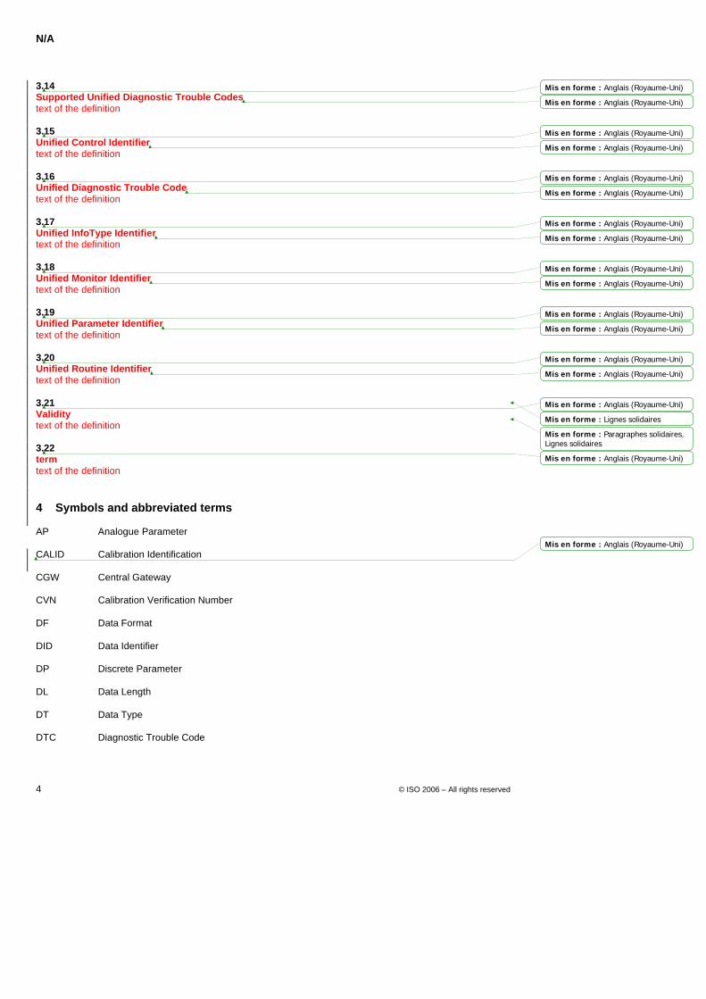
3.14 Supported Unified Diagnostic Trouble Codes text of the definition
3.15 Unified Control Identifier text of the definition
3.16 Unified Diagnostic Trouble Code text of the definition
3.17 Unified InfoType Identifier text of the definition
3.18 Unified Monitor Identifier text of the definition
3.19 Unified Parameter Identifier text of the definition
3.20 Unified Routine Identifier text of the definition
3.21 Validity text of the definition
3.22 term text of the definition
4 Symbols and abbreviated terms
AP Analogue Parameter
CALID Calibration Identification
CGW Central Gateway
CVN Calibration Verification Number
DF Data Format
DID Data Identifier
DP Discrete Parameter
DL Data Length
DT Data Type
DTC Diagnostic Trouble Code
Mis en forme : Anglais (Royaume-Uni)
Mis en forme : Anglais (Royaume-Uni)
Mis en forme : Anglais (Royaume-Uni)
Mis en forme : Anglais (Royaume-Uni)
Mis en forme : Anglais (Royaume-Uni)
Mis en forme : Anglais (Royaume-Uni)
Mis en forme : Anglais (Royaume-Uni)
Mis en forme : Anglais (Royaume-Uni)
Mis en forme : Anglais (Royaume-Uni)
Mis en forme : Anglais (Royaume-Uni)
Mis en forme : Anglais (Royaume-Uni)
Mis en forme : Anglais (Royaume-Uni)
Mis en forme : Anglais (Royaume-Uni)
Mis en forme : Anglais (Royaume-Uni)
Mis en forme : Anglais (Royaume-Uni)
Mis en forme : Lignes solidaires
Mis en forme : Paragraphes solidaires,Lignes solidaires
Mis en forme : Anglais (Royaume-Uni)
Mis en forme : Anglais (Royaume-Uni)
N/A
© ISO 2006 – All rights reserved 5
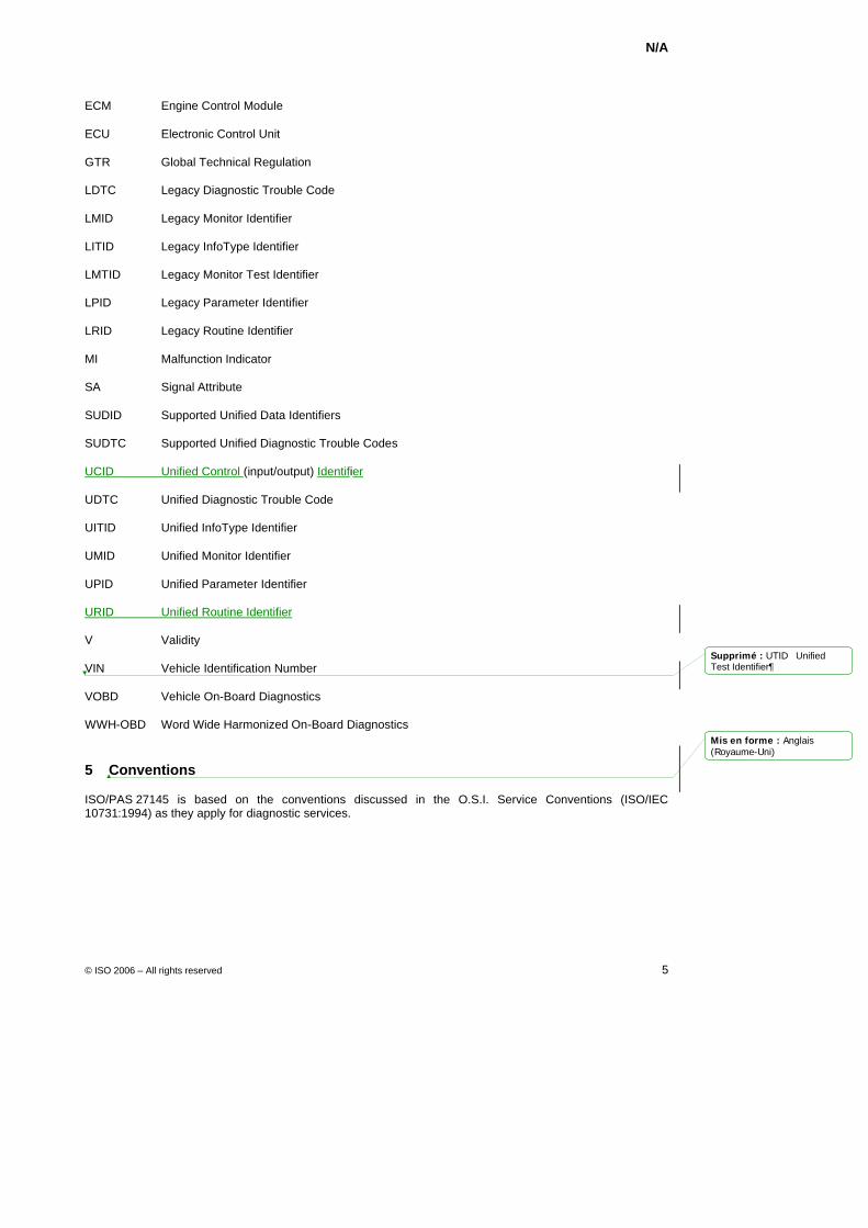
ECM Engine Control Module
ECU Electronic Control Unit
GTR Global Technical Regulation
LDTC Legacy Diagnostic Trouble Code
LMID Legacy Monitor Identifier
LITID Legacy InfoType Identifier
LMTID Legacy Monitor Test Identifier
LPID Legacy Parameter Identifier
LRID Legacy Routine Identifier
MI Malfunction Indicator
SA Signal Attribute
SUDID Supported Unified Data Identifiers
SUDTC Supported Unified Diagnostic Trouble Codes
UCID Unified Control (input/output) Identifier
UDTC Unified Diagnostic Trouble Code
UITID Unified InfoType Identifier
UMID Unified Monitor Identifier
UPID Unified Parameter Identifier
URID Unified Routine Identifier
V Validity
VIN Vehicle Identification Number
VOBD Vehicle On-Board Diagnostics
WWH-OBD Word Wide Harmonized On-Board Diagnostics
5 Conventions
ISO/PAS 27145 is based on the conventions discussed in the O.S.I. Service Conventions (ISO/IEC 10731:1994) as they apply for diagnostic services.
Mis en forme : Anglais(Royaume-Uni)
Supprimé : UTID Unified Test Identifier
N/A
6 © ISO 2006 – All rights reserved
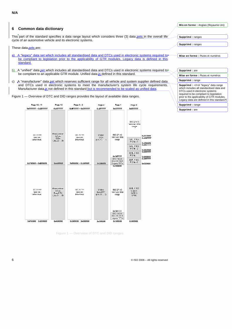
6 Common data dictionary
This part of the standard specifies a data range layout which considers three (3) data sets in the overall life cycle of an automotive vehicle and its electronic systems.
These data sets are:
a) A "legacy" data set which includes all standardised data and DTCs used in electronic systems required to be compliant to legislation prior to the applicability of GTR modules. Legacy data is defined in this standard.
b) A "unified" data set which includes all standardised data and DTCs used in electronic systems required to be compliant to an applicable GTR module. Unified data is defined in this standard.
c) A "manufacturer" data set which reserves sufficient range for all vehicle and system supplier defined data and DTCs used in electronic systems to meet the manufacturer's system life cycle requirements. Manufacturer data is not defined in this standard but is recommended to be scaled as unified data.
Figure 1 — Overview of DTC and DID ranges provides the layout of available data ranges.
Figure 1 — Overview of DTC and DID ranges
Mis en forme : Anglais (Royaume-Uni)
Mise en forme : Puces et numéros
Mise en forme : Puces et numéros
Supprimé : ranges
Supprimé : ranges
Supprimé : are
Supprimé : range
Supprimé : <#>A "legacy" data range which includes all standardised data and DTCs used in electronic systems required to be compliant to legislation prior to the applicability of GTR modules. Legacy data are defined in this standard.
Supprimé : range
Supprimé : are
N/A
© ISO 2006 – All rights reserved 7
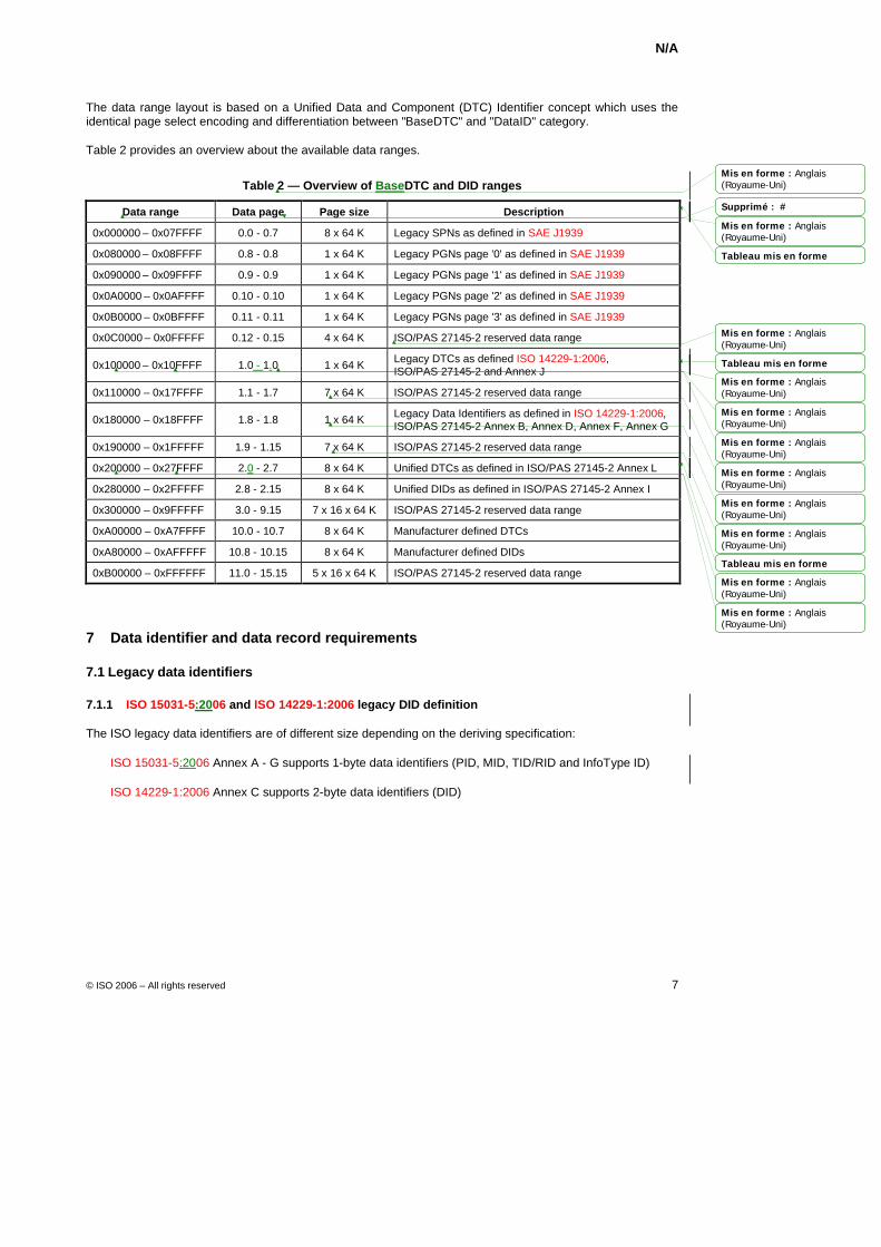
The data range layout is based on a Unified Data and Component (DTC) Identifier concept which uses the identical page select encoding and differentiation between "BaseDTC" and "DataID" category.
Table 2 provides an overview about the available data ranges.
Table 2 — Overview of BaseDTC and DID ranges
Data range Data page Page size Description
0x000000 – 0x07FFFF 0.0 - 0.7 8 x 64 K Legacy SPNs as defined in SAE J1939
0x080000 – 0x08FFFF 0.8 - 0.8 1 x 64 K Legacy PGNs page '0' as defined in SAE J1939
0x090000 – 0x09FFFF 0.9 - 0.9 1 x 64 K Legacy PGNs page '1' as defined in SAE J1939
0x0A0000 – 0x0AFFFF 0.10 - 0.10 1 x 64 K Legacy PGNs page '2' as defined in SAE J1939
0x0B0000 – 0x0BFFFF 0.11 - 0.11 1 x 64 K Legacy PGNs page '3' as defined in SAE J1939
0x0C0000 – 0x0FFFFF 0.12 - 0.15 4 x 64 K ISO/PAS 27145-2 reserved data range
0x100000 – 0x10FFFF 1.0 - 1.0 1 x 64 K Legacy DTCs as defined ISO 14229-1:2006, ISO/PAS 27145-2 and Annex J
0x110000 – 0x17FFFF 1.1 - 1.7 7 x 64 K ISO/PAS 27145-2 reserved data range
0x180000 – 0x18FFFF 1.8 - 1.8 1 x 64 K Legacy Data Identifiers as defined in ISO 14229-1:2006, ISO/PAS 27145-2 Annex B, Annex D, Annex F, Annex G
0x190000 – 0x1FFFFF 1.9 - 1.15 7 x 64 K ISO/PAS 27145-2 reserved data range
0x200000 – 0x27FFFF 2.0 - 2.7 8 x 64 K Unified DTCs as defined in ISO/PAS 27145-2 Annex L
0x280000 – 0x2FFFFF 2.8 - 2.15 8 x 64 K Unified DIDs as defined in ISO/PAS 27145-2 Annex I
0x300000 – 0x9FFFFF 3.0 - 9.15 7 x 16 x 64 K ISO/PAS 27145-2 reserved data range
0xA00000 – 0xA7FFFF 10.0 - 10.7 8 x 64 K Manufacturer defined DTCs
0xA80000 – 0xAFFFFF 10.8 - 10.15 8 x 64 K Manufacturer defined DIDs
0xB00000 – 0xFFFFFF 11.0 - 15.15 5 x 16 x 64 K ISO/PAS 27145-2 reserved data range
7 Data identifier and data record requirements
7.1 Legacy data identifiers
7.1.1 ISO 15031-5:2006 and ISO 14229-1:2006 legacy DID definition
The ISO legacy data identifiers are of different size depending on the deriving specification:
ISO 15031-5:2006 Annex A - G supports 1-byte data identifiers (PID, MID, TID/RID and InfoType ID)
ISO 14229-1:2006 Annex C supports 2-byte data identifiers (DID)
Mis en forme : Anglais(Royaume-Uni)
Mis en forme : Anglais(Royaume-Uni)
Tableau mis en forme
Mis en forme : Anglais(Royaume-Uni)
Tableau mis en forme
Mis en forme : Anglais(Royaume-Uni)
Mis en forme : Anglais(Royaume-Uni)
Mis en forme : Anglais(Royaume-Uni)
Mis en forme : Anglais(Royaume-Uni)
Mis en forme : Anglais(Royaume-Uni)
Mis en forme : Anglais(Royaume-Uni)
Tableau mis en forme
Mis en forme : Anglais(Royaume-Uni)
Mis en forme : Anglais(Royaume-Uni)
Supprimé : #
N/A
8 © ISO 2006 – All rights reserved
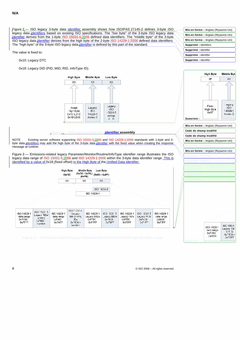
Figure 2 — ISO legacy 3-byte data identifier assembly shows how ISO/PAS 27145-2 defines 3-byte ISO legacy data identifiers based on existing ISO specifications. The "low byte" of the 3-byte ISO legacy data identifier derives from the 1-byte ISO 15031-5:2006 defined data identifiers. The "middle byte" of the 3-byte ISO legacy data identifier derives from the high byte of the 2-byte ISO 14229-1:2006 defined data identifiers. The "high byte" of the 3-byte ISO legacy data identifier is defined by this part of the standard.
The value is fixed to:
0x10: Legacy DTC
0x18: Legacy DID (PID, MID, RID, InfoType ID).
Figure 2 — ISO legacy 3-byte data identifier assembly
NOTE Existing server software supporting ISO 15031-5:2006 and ISO 14229-1:2006 standards with 1-byte and 2-byte data identifiers may add the high byte of the 3-byte data identifier with the fixed value when creating the response message at runtime.
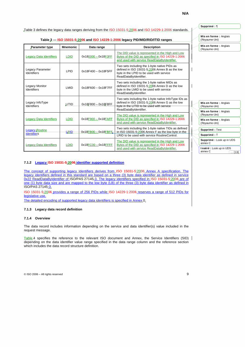
Figure 3 — Emissions-related legacy Parameter/Monitor/Routine/InfoType identifier range illustrates the ISO legacy data range of ISO 15031-5:2006 and ISO 14229-1:2006 within the 3-byte data identifier range. This is identified by a value of 0x18 (fixed offset) in the High Byte of the Unified Data Identifier.
Figure 3 — Emissions-related legacy Parameter/Monitor/Routine/InfoType identifier range
Mis en forme : Anglais (Royaume-Uni)
Mis en forme : Anglais (Royaume-Uni)
Mis en forme : Anglais (Royaume-Uni)
Mis en forme : Anglais (Royaume-Uni)
Code de champ modifié
Code de champ modifié
Mis en forme : Anglais (Royaume-Uni)
Mis en forme : Anglais (Royaume-Uni)
Supprimé : identifers
Supprimé : identifer
Supprimé : identifer
Supprimé : identifer
Supprimé :
Supprimé : identifer
Supprimé : identifers
Supprimé : identifer
Commentaire : Change figure (box on the very right)
Commentaire :
Commentaire :
Supprimé :
N/A
© ISO 2006 – All rights reserved 9
Table 3 defines the legacy data ranges deriving from the ISO 15031-5:2006 and ISO 14229-1:2006 standards.
Table 3 — ISO 15031-5:2006 and ISO 14229-1:2006 legacy PID/MID/RID/ITID ranges
Parameter type Mnemonic Data range Description
Legacy Data Identifiers LDID 0x180000 – 0x18F3FF The DID value is represented in the High and Low Bytes of the DID as specified in ISO 14229-1:2006 and used with service ReadDataByIdentifier.
Legacy Parameter Identifiers LPID 0x18F400 – 0x18F5FF
Two sets including the 1-byte native PIDs as defined in ISO 15031-5:2006 Annex B as the low byte in the LPID to be used with service ReadDataByIdentifier.
Legacy Monitor Identifiers LMID 0x18F600 – 0x18F7FF
Two sets including the 1-byte native MIDs as defined in ISO 15031-5:2006 Annex D as the low byte in the LMID to be used with service ReadDataByIdentifier.
Legacy InfoType Identifiers LITID 0x18F800 – 0x18F8FF
Two sets including the 1-byte native InfoType IDs as defined in ISO 15031-5:2006 Annex G as the low byte in the LITID to be used with service ReadDataByIdentifier.
Legacy Data Identifiers LDID 0x18F900 – 0x18FAFF The DID value is represented in the High and Low Bytes of the DID as specified in ISO 14229-1:2006 and used with service ReadDataByIdentifier.
Legacy Routine Identifiers LRID 0x18FB00 – 0x18FBFF
Two sets including the 1-byte native TIDs as defined in ISO 15031-5:2006 Annex F as the low byte in the LRID to be used with service RoutineControl.
Legacy Data Identifiers LDID 0x18FC00 – 0x18FFFF The DID value is represented in the High and Low Bytes of the DID as specified in ISO 14229-1:2006 and used with service ReadDataByIdentifier.
7.1.2 Legacy ISO 15031-5:2006 identifier supported definition
The concept of supporting legacy Identifiers derives from ISO 15031-5:2006 Annex A specification. The legacy identifiers defined in this standard are based on a three (3) byte data identifier as defined in service 0x22 ReadDataByIdentifier of ISO/PAS 27145-3. The legacy identifiers specified in ISO 15031-5:2006 are of one (1) byte data size and are mapped to the low byte (LB) of the three (3) byte data identifier as defined in ISO/PAS 27145-3.
ISO 15031-5:2006 provides a range of 256 PIDs while ISO 14229-1:2006 reserves a range of 512 PIDs for legislative use. The detailed encoding of supported legacy data identifiers is specified in Annex 0.
7.1.3 Legacy data record definition
7.1.4 Overview
The data record includes information depending on the service and data identifier(s) value included in the request message.
Table 4 specifies the reference to the relevant ISO document and Annex, the Service Identifiers (SID) depending on the data identifier value range specified in the data range column and the reference section which includes the data record structure definition.
Mis en forme : Anglais(Royaume-Uni)
Mis en forme : Anglais(Royaume-Uni)
Mis en forme : Anglais(Royaume-Uni)
Mis en forme : Anglais(Royaume-Uni)
Mis en forme : Anglais(Royaume-Uni)
Supprimé : 
Supprimé : Test
Supprimé : T
Supprimé : Look up in UDS annex C
Inséré : Look up in UDS annex C ... [13]
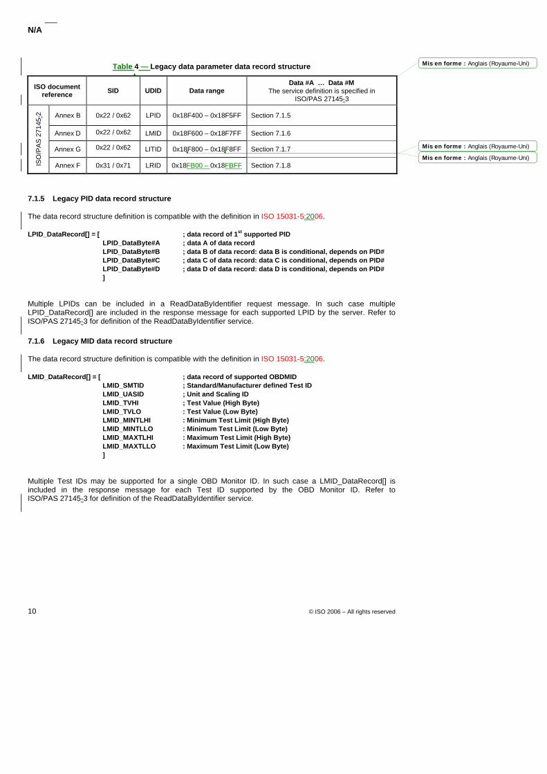
N/A
10 © ISO 2006 – All rights reserved
Table 4 — Legacy data parameter data record structure
ISO document reference SID UDID Data range
Data #A … Data #M The service definition is specified in
ISO/PAS 27145-3
Annex B 0x22 / 0x62 LPID 0x18F400 – 0x18F5FF Section 7.1.5
Annex D 0x22 / 0x62 LMID 0x18F600 – 0x18F7FF Section 7.1.6
Annex G 0x22 / 0x62 LITID 0x18F800 – 0x18F8FF Section 7.1.7
ISO
/PA
S 2
7145
-2
Annex F 0x31 / 0x71 LRID 0x18FB00 – 0x18FBFF Section 7.1.8
7.1.5 Legacy PID data record structure
The data record structure definition is compatible with the definition in ISO 15031-5:2006.
LPID_DataRecord[] = [ ; data record of 1st supported PID LPID_DataByte#A ; data A of data record LPID_DataByte#B ; data B of data record: data B is conditional, depends on PID# LPID_DataByte#C ; data C of data record: data C is conditional, depends on PID# LPID_DataByte#D ; data D of data record: data D is conditional, depends on PID# ]
Multiple LPIDs can be included in a ReadDataByIdentifier request message. In such case multiple LPID_DataRecord[] are included in the response message for each supported LPID by the server. Refer to ISO/PAS 27145-3 for definition of the ReadDataByIdentifier service.
7.1.6 Legacy MID data record structure
The data record structure definition is compatible with the definition in ISO 15031-5:2006.
LMID_DataRecord[] = [ ; data record of supported OBDMID LMID_SMTID ; Standard/Manufacturer defined Test ID LMID_UASID ; Unit and Scaling ID LMID_TVHI ; Test Value (High Byte) LMID_TVLO : Test Value (Low Byte) LMID_MINTLHI : Minimum Test Limit (High Byte) LMID_MINTLLO : Minimum Test Limit (Low Byte) LMID_MAXTLHI : Maximum Test Limit (High Byte) LMID_MAXTLLO : Maximum Test Limit (Low Byte) ]
Multiple Test IDs may be supported for a single OBD Monitor ID. In such case a LMID_DataRecord[] is included in the response message for each Test ID supported by the OBD Monitor ID. Refer to ISO/PAS 27145-3 for definition of the ReadDataByIdentifier service.
Mis en forme : Anglais (Royaume-Uni)
Mis en forme : Anglais (Royaume-Uni)
Mis en forme : Anglais (Royaume-Uni)
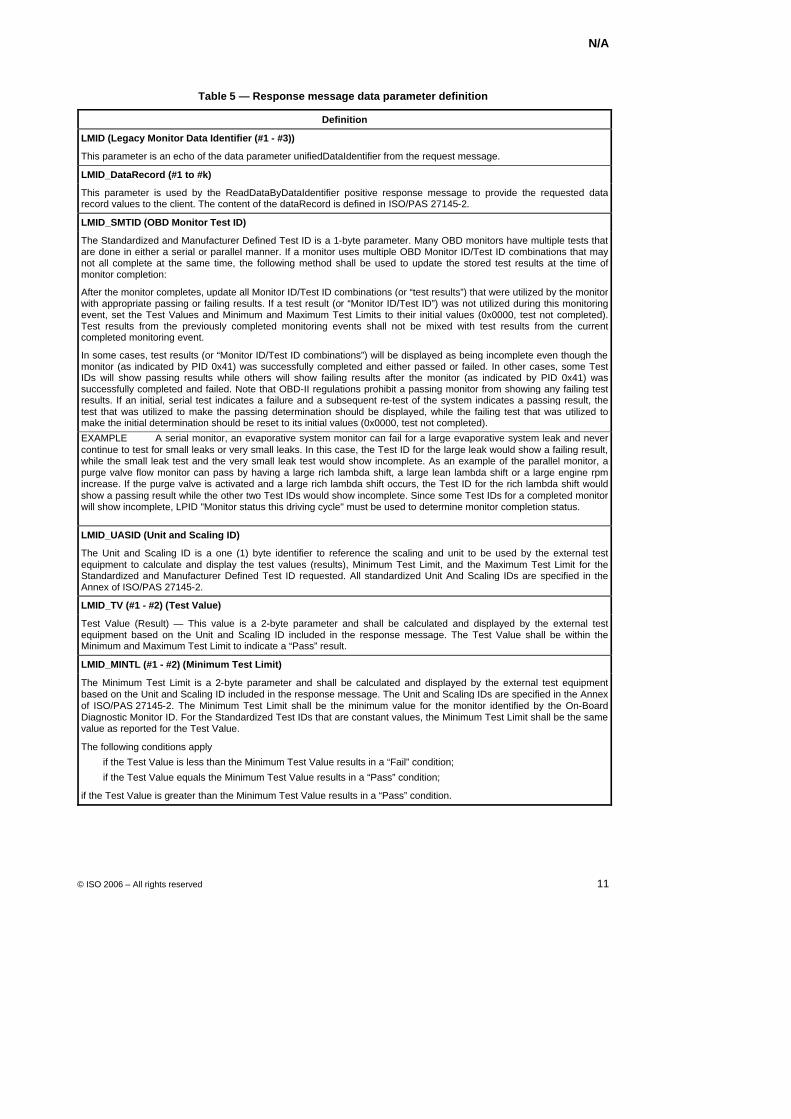
N/A
© ISO 2006 – All rights reserved 11
Table 5 — Response message data parameter definition
Definition
LMID (Legacy Monitor Data Identifier (#1 - #3))
This parameter is an echo of the data parameter unifiedDataIdentifier from the request message.
LMID_DataRecord (#1 to #k)
This parameter is used by the ReadDataByDataIdentifier positive response message to provide the requested data record values to the client. The content of the dataRecord is defined in ISO/PAS 27145-2.
LMID_SMTID (OBD Monitor Test ID)
The Standardized and Manufacturer Defined Test ID is a 1-byte parameter. Many OBD monitors have multiple tests that are done in either a serial or parallel manner. If a monitor uses multiple OBD Monitor ID/Test ID combinations that may not all complete at the same time, the following method shall be used to update the stored test results at the time of monitor completion:
After the monitor completes, update all Monitor ID/Test ID combinations (or “test results”) that were utilized by the monitor with appropriate passing or failing results. If a test result (or “Monitor ID/Test ID”) was not utilized during this monitoring event, set the Test Values and Minimum and Maximum Test Limits to their initial values (0x0000, test not completed). Test results from the previously completed monitoring events shall not be mixed with test results from the current completed monitoring event.
In some cases, test results (or “Monitor ID/Test ID combinations”) will be displayed as being incomplete even though the monitor (as indicated by PID 0x41) was successfully completed and either passed or failed. In other cases, some Test IDs will show passing results while others will show failing results after the monitor (as indicated by PID 0x41) was successfully completed and failed. Note that OBD-II regulations prohibit a passing monitor from showing any failing test results. If an initial, serial test indicates a failure and a subsequent re-test of the system indicates a passing result, the test that was utilized to make the passing determination should be displayed, while the failing test that was utilized to make the initial determination should be reset to its initial values (0x0000, test not completed).
EXAMPLE A serial monitor, an evaporative system monitor can fail for a large evaporative system leak and never continue to test for small leaks or very small leaks. In this case, the Test ID for the large leak would show a failing result, while the small leak test and the very small leak test would show incomplete. As an example of the parallel monitor, a purge valve flow monitor can pass by having a large rich lambda shift, a large lean lambda shift or a large engine rpm increase. If the purge valve is activated and a large rich lambda shift occurs, the Test ID for the rich lambda shift would show a passing result while the other two Test IDs would show incomplete. Since some Test IDs for a completed monitor will show incomplete, LPID "Monitor status this driving cycle" must be used to determine monitor completion status.
LMID_UASID (Unit and Scaling ID)
The Unit and Scaling ID is a one (1) byte identifier to reference the scaling and unit to be used by the external test equipment to calculate and display the test values (results), Minimum Test Limit, and the Maximum Test Limit for the Standardized and Manufacturer Defined Test ID requested. All standardized Unit And Scaling IDs are specified in the Annex of ISO/PAS 27145-2.
LMID_TV (#1 - #2) (Test Value)
Test Value (Result) — This value is a 2-byte parameter and shall be calculated and displayed by the external test equipment based on the Unit and Scaling ID included in the response message. The Test Value shall be within the Minimum and Maximum Test Limit to indicate a “Pass” result.
LMID_MINTL (#1 - #2) (Minimum Test Limit)
The Minimum Test Limit is a 2-byte parameter and shall be calculated and displayed by the external test equipment based on the Unit and Scaling ID included in the response message. The Unit and Scaling IDs are specified in the Annex of ISO/PAS 27145-2. The Minimum Test Limit shall be the minimum value for the monitor identified by the On-Board Diagnostic Monitor ID. For the Standardized Test IDs that are constant values, the Minimum Test Limit shall be the same value as reported for the Test Value.
The following conditions apply
if the Test Value is less than the Minimum Test Value results in a “Fail” condition;
if the Test Value equals the Minimum Test Value results in a “Pass” condition;
if the Test Value is greater than the Minimum Test Value results in a “Pass” condition.
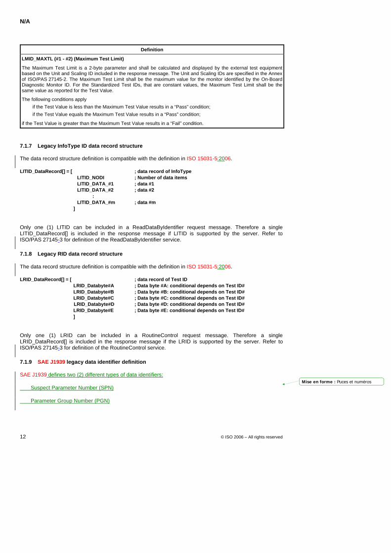
N/A
12 © ISO 2006 – All rights reserved
Definition
LMID_MAXTL (#1 - #2) (Maximum Test Limit)
The Maximum Test Limit is a 2-byte parameter and shall be calculated and displayed by the external test equipment based on the Unit and Scaling ID included in the response message. The Unit and Scaling IDs are specified in the Annex of ISO/PAS 27145-2. The Maximum Test Limit shall be the maximum value for the monitor identified by the On-Board Diagnostic Monitor ID. For the Standardized Test IDs, that are constant values, the Maximum Test Limit shall be the same value as reported for the Test Value.
The following conditions apply
if the Test Value is less than the Maximum Test Value results in a “Pass” condition;
if the Test Value equals the Maximum Test Value results in a “Pass” condition;
if the Test Value is greater than the Maximum Test Value results in a “Fail” condition.
7.1.7 Legacy InfoType ID data record structure
The data record structure definition is compatible with the definition in ISO 15031-5:2006.
LITID_DataRecord[] = [ ; data record of InfoType LITID_NODI ; Number of data items LITID_DATA_#1 ; data #1 LITID_DATA_#2 ; data #2 : LITID_DATA_#m ; data #m
]
Only one (1) LITID can be included in a ReadDataByIdentifier request message. Therefore a single LITID_DataRecord[] is included in the response message if LITID is supported by the server. Refer to ISO/PAS 27145-3 for definition of the ReadDataByIdentifier service.
7.1.8 Legacy RID data record structure
The data record structure definition is compatible with the definition in ISO 15031-5:2006.
LRID_DataRecord[] = [ ; data record of Test ID LRID_Databyte#A ; Data byte #A: conditional depends on Test ID# LRID_Databyte#B ; Data byte #B: conditional depends on Test ID# LRID_Databyte#C ; Data byte #C: conditional depends on Test ID# LRID_Databyte#D ; Data byte #D: conditional depends on Test ID# LRID_Databyte#E ; Data byte #E: conditional depends on Test ID# ]
Only one (1) LRID can be included in a RoutineControl request message. Therefore a single LRID_DataRecord[] is included in the response message if the LRID is supported by the server. Refer to ISO/PAS 27145-3 for definition of the RoutineControl service.
7.1.9 SAE J1939 legacy data identifier definition
SAE J1939 defines two (2) different types of data identifiers:
Suspect Parameter Number (SPN)
Parameter Group Number (PGN)
Mise en forme : Puces et numéros
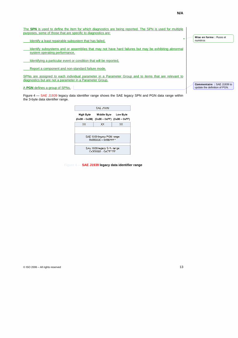
N/A
© ISO 2006 – All rights reserved 13
The SPN is used to define the item for which diagnostics are being reported. The SPN is used for multiple purposes, some of those that are specific to diagnostics are:
Identify a least repairable subsystem that has failed,
Identify subsystems and or assemblies that may not have hard failures but may be exhibiting abnormal system operating performance,
Identifying a particular event or condition that will be reported,
Report a component and non-standard failure mode.
SPNs are assigned to each individual parameter in a Parameter Group and to items that are relevant to diagnostics but are not a parameter in a Parameter Group.
A PGN defines a group of SPNs.
Figure 4 — SAE J1939 legacy data identifier range shows the SAE legacy SPN and PGN data range within the 3-byte data identifier range.
Figure 4 — SAE J1939 legacy data identifier range
Mise en forme : Puces etnuméros
Commentaire : SAE J1939 to update the definition of PGN.
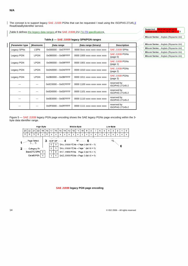
N/A
14 © ISO 2006 – All rights reserved
The concept is to support legacy SAE J1939 PGNs that can be requested / read using the ISO/PAS 27145-3 ReadDataByIdentifier service.
Table 6 defines the legacy data ranges of the SAE J1939-21/-71/-73 specifications.
Table 6 — SAE J1939 legacy SPN/PGN ranges
Parameter type Mnemonic Data range Data range (binary) Description
Legacy SPNs LSPN 0x000000 – 0x07FFFF 0000 0xxx xxxx xxxx xxxx xxxx SAE J1939 SPNs
Legacy PGN LPGN 0x080000 – 0x08FFFF 0000 1000 xxxx xxxx xxxx xxxx SAE J1939 PGNs (page 0)
Legacy PGN LPGN 0x090000 – 0x09FFFF 0000 1001 xxxx xxxx xxxx xxxx SAE J1939 PGNs (page 1)
Legacy PGN LPGN 0x0A0000 – 0x0AFFFF 0000 1010 xxxx xxxx xxxx xxxx SAE J1939 PGNs (page 2)
Legacy PGN LPGN 0x0B0000 – 0x0BFFFF 0000 1011 xxxx xxxx xxxx xxxx SAE J1939 PGNs (page 3)
--- --- 0x0C0000 – 0x0CFFFF 0000 1100 xxxx xxxx xxxx xxxx reserved by ISO/PAS 27145-2
--- --- 0x0D0000 – 0x0DFFFF 0000 1101 xxxx xxxx xxxx xxxx reserved by ISO/PAS 27145-2
--- --- 0x0E0000 – 0x0EFFFF 0000 1110 xxxx xxxx xxxx xxxx reserved by ISO/PAS 27145-2
--- --- 0x0F0000 – 0x0FFFFF 0000 1111 xxxx xxxx xxxx xxxx reserved by ISO/PAS 27145-2
Figure 5 — SAE J1939 legacy PGN page encoding shows the SAE legacy PGNs page encoding within the 3-byte data identifier range.
Key
1 Page Select: 0 - 15 2 Category: BaseDTC/SPN = 0, DataID/PGN = 1 3 EDP: Extended Data Page 4 DP: Data Page 5 PF: PDU Format 6: PS: PDU Specific
Figure 5 — SAE J1939 legacy PGN page encoding
Mis en forme : Anglais (Royaume-Uni)
Mis en forme : Anglais (Royaume-Uni)
Mis en forme : Anglais (Royaume-Uni)
Mis en forme : Anglais (Royaume-Uni)
Mis en forme : Anglais (Royaume-Uni)
Supprimé : Need better picture to illustrate data ranges, DP 0, DP 1, … 
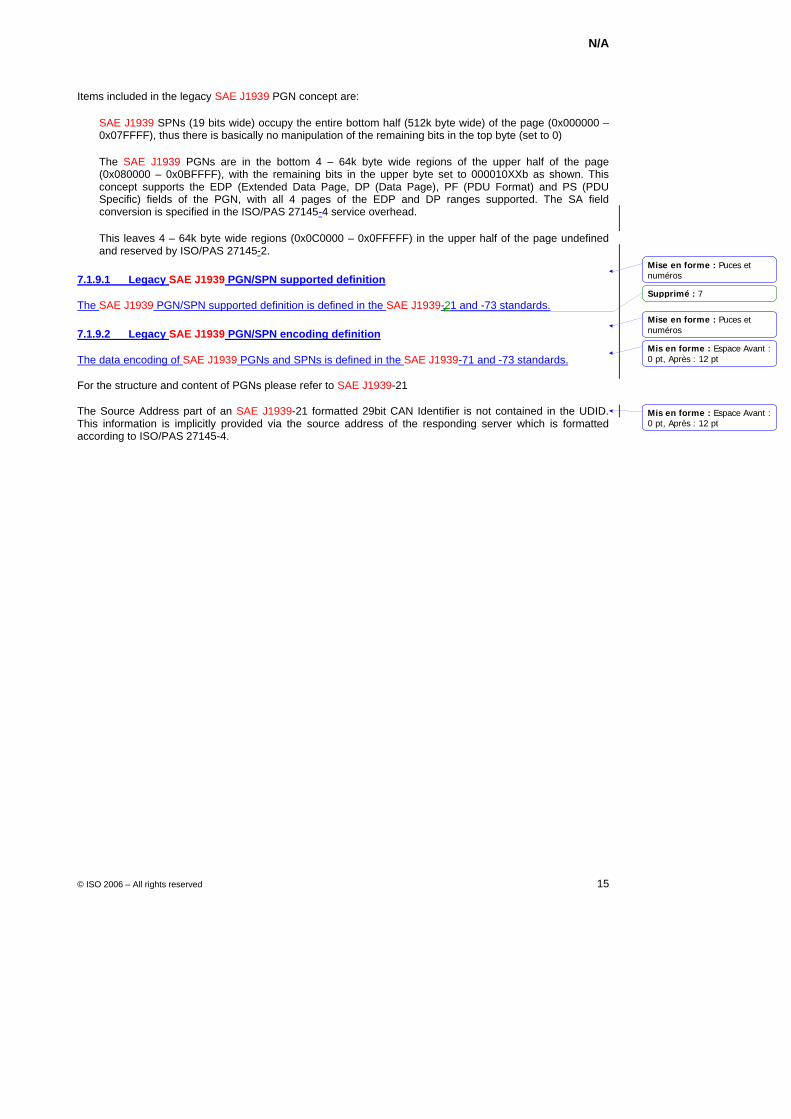
N/A
© ISO 2006 – All rights reserved 15
Items included in the legacy SAE J1939 PGN concept are:
SAE J1939 SPNs (19 bits wide) occupy the entire bottom half (512k byte wide) of the page (0x000000 – 0x07FFFF), thus there is basically no manipulation of the remaining bits in the top byte (set to 0)
The SAE J1939 PGNs are in the bottom 4 – 64k byte wide regions of the upper half of the page (0x080000 – 0x0BFFFF), with the remaining bits in the upper byte set to 000010XXb as shown. This concept supports the EDP (Extended Data Page, DP (Data Page), PF (PDU Format) and PS (PDU Specific) fields of the PGN, with all 4 pages of the EDP and DP ranges supported. The SA field conversion is specified in the ISO/PAS 27145-4 service overhead.
This leaves 4 – 64k byte wide regions (0x0C0000 – 0x0FFFFF) in the upper half of the page undefined and reserved by ISO/PAS 27145-2.
7.1.9.1 Legacy SAE J1939 PGN/SPN supported definition
The SAE J1939 PGN/SPN supported definition is defined in the SAE J1939-21 and -73 standards.
7.1.9.2 Legacy SAE J1939 PGN/SPN encoding definition
The data encoding of SAE J1939 PGNs and SPNs is defined in the SAE J1939-71 and -73 standards.
For the structure and content of PGNs please refer to SAE J1939-21
The Source Address part of an SAE J1939-21 formatted 29bit CAN Identifier is not contained in the UDID. This information is implicitly provided via the source address of the responding server which is formatted according to ISO/PAS 27145-4.
Mise en forme : Puces etnuméros
Mise en forme : Puces etnuméros
Mis en forme : Espace Avant :0 pt, Après : 12 pt
Mis en forme : Espace Avant :0 pt, Après : 12 pt
Supprimé : 7
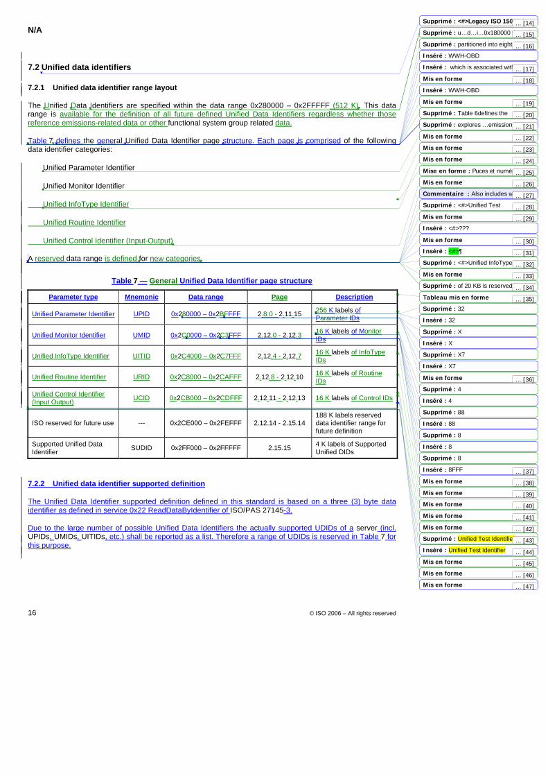
N/A
16 © ISO 2006 – All rights reserved
7.2 Unified data identifiers
7.2.1 Unified data identifier range layout
The Unified Data Identifiers are specified within the data range 0x280000 – 0x2FFFFF (512 K). This data range is available for the definition of all future defined Unified Data Identifiers regardless whether those reference emissions-related data or other functional system group related data.
Table 7 defines the general Unified Data Identifier page structure. Each page is comprised of the following data identifier categories:
Unified Parameter Identifier
Unified Monitor Identifier
Unified InfoType Identifier
Unified Routine Identifier
Unified Control Identifier (Input-Output)
A reserved data range is defined for new categories.
Table 7 — General Unified Data Identifier page structure
Parameter type Mnemonic Data range Page Description
Unified Parameter Identifier UPID 0x280000 – 0x2BFFFF 2.8.0 - 2.11.15 256 K labels of Parameter IDs
Unified Monitor Identifier UMID 0x2C0000 – 0x2C3FFF 2.12.0 - 2.12.3 16 K labels of Monitor IDs
Unified InfoType Identifier UITID 0x2C4000 – 0x2C7FFF 2.12.4 - 2.12.7 16 K labels of InfoType IDs
Unified Routine Identifier URID 0x2C8000 – 0x2CAFFF 2.12.8 - 2.12.10 16 K labels of Routine IDs
Unified Control Identifier (Input Output) UCID 0x2CB000 – 0x2CDFFF 2.12.11 - 2.12.13 16 K labels of Control IDs
ISO reserved for future use --- 0x2CE000 – 0x2FEFFF 2.12.14 - 2.15.14 188 K labels reserved data identifier range for future definition
Supported Unified Data Identifier SUDID 0x2FF000 – 0x2FFFFF 2.15.15 4 K labels of Supported
Unified DIDs
7.2.2 Unified data identifier supported definition
The Unified Data Identifier supported definition defined in this standard is based on a three (3) byte data identifier as defined in service 0x22 ReadDataByIdentifier of ISO/PAS 27145-3.
Due to the large number of possible Unified Data Identifiers the actually supported UDIDs of a server (incl. UPIDs, UMIDs, UITIDs, etc.) shall be reported as a list. Therefore a range of UDIDs is reserved in Table 7 for this purpose.
Mis en forme
Mis en forme
Mis en forme
Mis en forme
Mis en forme
Mis en forme
Mis en forme
Mis en forme
Mise en forme : Puces et numéros
Mis en forme
Mis en forme
Mis en forme
Mis en forme
Tableau mis en forme
Mis en forme
Mis en forme
Mis en forme
Mis en forme
Mis en forme
Mis en forme
Supprimé : <#>Legacy ISO 15031-5 data encoding definition¶Supprimé : u…d…i…0x180000 through 0x1FFFFFSupprimé : partitioned into eight (8) pages of 64 KB segments. Page 1.8 Inséré : WWH-OBD
Inséré : which is associated with page 1.8
Inséré : WWH-OBD
Supprimé : Table 6defines the emissions-related Unified Data Identifier Supprimé : explores …emissions-related …1.8…Emissions-related data
Commentaire : Also includes what was formerly known as TestID Supprimé : <#>Unified Test Identifier???
Inséré : <#>???
Inséré : <#>¶<#>Unified Input-Output Control IdentifierSupprimé : <#>Unified InfoType Identifier
Supprimé : of 20 KB is reserved …a future defined new category(ies)
Supprimé : 32
Inséré : 32
Supprimé : X
Inséré : X
Supprimé : X7
Inséré : X7
Supprimé : 4
Inséré : 4
Supprimé : 88
Inséré : 88
Supprimé : 8
Inséré : 8
Supprimé : 8
Inséré : 8FFF
Supprimé : Unified Test Identifier
Inséré : Unified Test Identifier
... [27]
... [26]
... [17]
... [35]
... [36]
... [25]
... [14]
... [29]
... [15]
... [28]
... [16]
... [24]
... [18]
... [37]
... [22]
... [38]
... [23]
... [39]
... [19]
... [40]
... [20]
... [41]
... [21]
... [42]
... [30]
... [43]
... [31]
... [44]
... [32]
... [45]
... [33]
... [46]
... [34]
... [47]
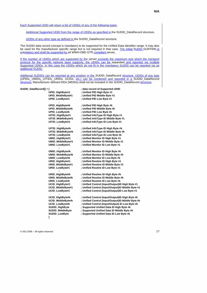
N/A
© ISO 2006 – All rights reserved 17
Each Supported UDID will return a list of UDIDs of any of the following types:
Additional Supported UDID from the range of UDIDs as specified in the SUDID_DataRecord structure,
UDIDs of any other type as defined in the SUDID_DataRecord structure.
The SUDID data record concept is mandatory to be supported for the Unified Data Identifier range. It may also be used for the manufacturer specific range but is not required in that case. The initial SUDID 0x2FF000 is mandatory and shall be supported by all WWH-OBD GTR compliant server.
If the number of UDIDs which are supported by the server exceeds the maximum size which the transport protocol for the specific network layer supports, the UDIDs can be separated and reported via multiple Supported UDIDs. In this case the UDIDs which do not fit in the mandatory SUDID can be reported via an additional SUDID.
Additional SUDIDs can be reported at any position in the SUDID_DataRecord structure. UDIDs of any type (UPIDs, UMIDs, UITIDs, URIDs, UCIDs, etc.) can be combined and reported in a SUDID_DataRecord structure. Manufacturer defined DIDs (MDIDs) shall not be included in the SUDID_DataRecord structure.
SUDID_DataRecord[] = [ ; data record of Supported UDID UPID_HighByte#1 ; Unified PID High Byte #1 UPID_MiddleByte#1 ; Unified PID Middle Byte #1 UPID_LowByte#1 ; Unified PID Low Byte #1 : UPID_HighByte#k ; Unified PID High Byte #k UPID_MiddleByte#k ; Unified PID Middle Byte #k UPID_LowByte#k ; Unified PID Low Byte #k UITID_HighByte#1 ; Unified InfoType ID High Byte #1 UITID_MiddleByte#1 ; Unified InfoType ID Middle Byte #1 UITID_LowByte#1 ; Unified InfoType ID Low Byte #1 : UITID_HighByte#k ; Unified InfoType ID High Byte #k UITID_MiddleByte#k ; Unified InfoType ID Middle Byte #k UITID_LowByte#k ; Unified InfoType ID Low Byte #k UMID_HighByte#1 ; Unified Monitor ID High Byte #1 UMID_MiddleByte#1 ; Unified Monitor ID Middle Byte #1 UMID_LowByte#1 ; Unified Monitor ID Low Byte #1 : UMID_HighByte#k ; Unified Monitor ID High Byte #k UMID_MiddleByte#k ; Unified Monitor ID Middle Byte #k UMID_LowByte#k ; Unified Monitor ID Low Byte #k URID_HighByte#1 ; Unified Routine ID High Byte #1 URID_MiddleByte#1 ; Unified Routine ID Middle Byte #1 URID_LowByte#1 ; Unified Routine ID Low Byte #1 : URID_HighByte#k ; Unified Routine ID High Byte #k URID_MiddleByte#k ; Unified Routine ID Middle Byte #k URID_LowByte#k ; Unified Routine ID Low Byte #k UCID_HighByte#1 ; Unified Control (Input/Output)ID High Byte #1 UCID_MiddleByte#1 ; Unified Control (Input/Output)ID Middle Byte #1 UCID_LowByte#1 ; Unified Control (Input/Output)ID Low Byte #1 : UCID_HighByte#k ; Unified Control (Input/Output)ID High Byte #k UCID_MiddleByte#k ; Unified Control (Input/Output)ID Middle Byte #k UCID_LowByte#k ; Unified Control (Input/Output) ID Low Byte #k SUDID_HighByte ; Supported Unified Data ID High Byte #k SUDID_MiddleByte ; Supported Unified Data ID Middle Byte #k SUDID_LowByte ; Supported Unified Data ID Low Byte #k ]
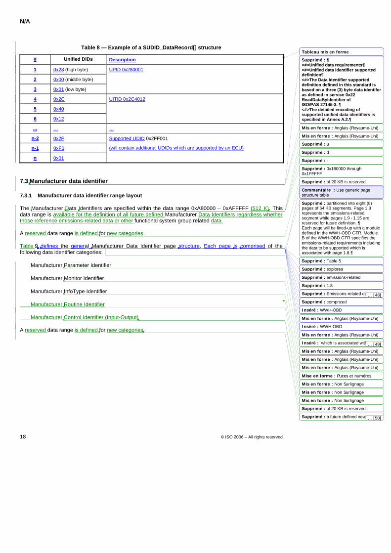
N/A
18 © ISO 2006 – All rights reserved
Table 8 — Example of a SUDID_DataRecord[] structure
# Unified DIDs Description
1 0x28 (high byte)
2 0x00 (middle byte)
3 0x01 (low byte)
UPID 0x280001
4 0x2C
5 0x40
6 0x12
UITID 0x2C4012
... … …
n-2 0x2F
n-1 0xF0
n 0x01
Supported UDID 0x2FF001
(will contain additional UDIDs which are supported by an ECU)
7.3 Manufacturer data identifier
7.3.1 Manufacturer data identifier range layout
The Manufacturer Data Identifiers are specified within the data range 0xA80000 – 0xAFFFFF (512 K). This data range is available for the definition of all future defined Manufacturer Data Identifiers regardless whether those reference emissions-related data or other functional system group related data.
A reserved data range is defined for new categories.
Table 9 defines the general Manufacturer Data Identifier page structure. Each page is comprised of the following data identifier categories:
Manufacturer Parameter Identifier
Manufacturer Monitor Identifier
Manufacturer InfoType Identifier
Manufacturer Routine Identifier
Manufacturer Control Identifier (Input-Output)
A reserved data range is defined for new categories.
Tableau mis en forme
Mis en forme : Anglais (Royaume-Uni)
Mis en forme : Anglais (Royaume-Uni)
Mis en forme : Anglais (Royaume-Uni)
Mis en forme : Anglais (Royaume-Uni)
Mis en forme : Non Surlignage
Mis en forme : Anglais (Royaume-Uni)
Mis en forme : Anglais (Royaume-Uni)
Mis en forme : Anglais (Royaume-Uni)
Mise en forme : Puces et numéros
Mis en forme : Non Surlignage
Mis en forme : Non Surlignage
Supprimé : ¶<#>Unified data requirements¶<#>Unified data identifier supported definition¶<#>The Data Identifier supported definition defined in this standard is based on a three (3) byte data identifer as defined in service 0x22 ReadDataByIdentifier of ISO/PAS 27145-3. ¶<#>The detailed encoding of supported unified data identifiers is specified in Annex A.2.
Supprimé : u
Supprimé : d
Supprimé : i
Supprimé : 0x180000 through 0x1FFFFF
Supprimé : of 20 KB is reserved
Commentaire : Use generic page structure table
Supprimé : partitioned into eight (8) pages of 64 KB segments. Page 1.8 represents the emissions-related segment while pages 1.9 - 1.15 are reserved for future definition. ¶Each page will be lined-up with a module defined in the WWH-OBD GTR. Module B of the WWH-OBD GTR specifies the emissions-related requirements including the data to be supported which is associated with page 1.8.
Supprimé : Table 5
Supprimé : explores
Supprimé : emissions-related
Supprimé : 1.8
Supprimé : Emissions-related data parameters areSupprimé : comprized
Inséré : WWH-OBD
Inséré : WWH-OBD
Inséré : which is associated with page 1.8
Supprimé : of 20 KB is reserved
Supprimé : a future defined new category(ies)
... [49]
... [48]
... [50]
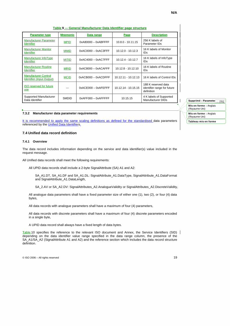
N/A
© ISO 2006 – All rights reserved 19
Table 9 — General Manufacturer Data Identifier page structure
Parameter type Mnemonic Data range Page Description
Manufacturer Parameter Identifier MPID 0xA80000 – 0xABFFFF 10.8.0 - 10.11.15 256 K labels of
Parameter IDs
Manufacturer Monitor Identifier MMID 0xAC0000 – 0xAC3FFF 10.12.0 - 10.12.3 16 K labels of Monitor
IDs
Manufacturer InfoType Identifier MITID 0xAC4000 – 0xAC7FFF 10.12.4 - 10.12.7 16 K labels of InfoType
IDs
Manufacturer Routine Identifier MRID 0xAC8000 – 0xACAFFF 10.12.8 - 10.12.10 16 K labels of Routine
IDs
Manufacturer Control Identifier (Input Output) MCID 0xACB000 – 0xACDFFF 10.12.11 - 10.12.13 16 K labels of Control IDs
ISO reserved for future use --- 0xACE000 – 0xAFEFFF 10.12.14 - 10.15.15
188 K reserved data identifier range for future definition
Supported Manufacturer Data Identifier SMDID 0xAFF000 – 0xAFFFFF 10.15.15 4 K labels of Supported
Manufacturer DIDs
7.3.2 Manufacturer data parameter requirements
It is recommended to apply the same scaling definitions as defined for the standardised data parameters referenced by the Unified Data Identifiers.
7.4 Unified data record definition
7.4.1 Overview
The data record includes information depending on the service and data identifier(s) value included in the request message.
All Unified data records shall meet the following requirements:
All UPID data records shall include a 2-byte SignalAttribute (SA) A1 and A2:
SA_A1.DT, SA_A1.DF and SA_A1.DL: SignalAttribute_A1.DataType, SignalAttribute_A1.DataFormat and SignalAttribute_A1.DataLength,
SA_2.AV or SA_A2.DV: SignalAttributes_A2.AnalogueValidity or SignalAttributes_A2.DiscreteValidity,
All analogue data parameters shall have a fixed parameter size of either one (1), two (2), or four (4) data bytes,
All data records with analogue parameters shall have a maximum of four (4) parameters,
All data records with discrete parameters shall have a maximum of four (4) discrete parameters encoded in a single byte,
A UPID data record shall always have a fixed length of data bytes.
Table 10 specifies the reference to the relevant ISO document and Annex, the Service Identifiers (SID) depending on the data identifier value range specified in the data range column, the presence of the SA_A1/SA_A2 (SignalAttribute A1 and A2) and the reference section which includes the data record structure definition.
Mis en forme : Anglais(Royaume-Uni)
Mis en forme : Anglais(Royaume-Uni)
Tableau mis en forme
Supprimé : Parameter type... [51]
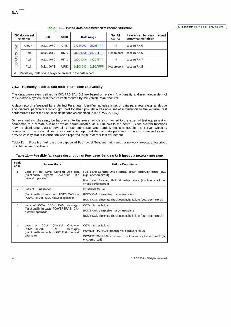
N/A
20 © ISO 2006 – All rights reserved
Table 10 — Unified data parameter data record structure
ISO document reference SID UDID Data range SA_A1
SA_A2 Reference to data record parameter definition
Annex I 0x22 / 0x62 UPID 0x280000 – 0x2BFFFF M section 7.4.5
Tbd. 0x22 / 0x62 UMID 0x2C0000 – 0x2C3FFF Not present section 7.4.6
Tbd. 0x22 / 0x62 UITID 0x2C4000 – 0x2C7FFF M section 7.4.7
ISO
/PA
S 2
7145
-2
Tbd. 0x31 / 0x71 URID 0x2C8000 – 0x2CAFFF Not present section 7.4.8
M Mandatory, data shall always be present in the data record
7.4.2 Remotely received sub-node information and validity
The data parameters defined in ISO/PAS 27145-2 are based on system functionality and are independent of the electronic system architecture implemented by the vehicle manufacturer.
A data record referenced by a Unified Parameter Identifier includes a set of data parameters e.g. analogue and discrete parameters which grouped together provide a valuable set of information to the external test equipment to meet the use case definitions as specified in ISO/PAS 27145-1.
Sensors and switches may be hard-wired to the server which is connected to the external test equipment or connected to a remote sub-node which communicates via a Sub-Net to the server. Since system functions may be distributed across several remote sub-nodes and partially implemented in the server which is connected to the external test equipment it is important that all data parameters based on sensed signals provide validity status information when reported to the external test equipment.
Table 11 — Possible fault case description of Fuel Level Sending Unit input via network message describes possible failure conditions.
Table 11 — Possible fault case description of Fuel Level Sending Unit input via network message
Fault case Failure Mode Failure Conditions
1 Loss of Fuel Level Sending Unit data (functionally impacts Powertrain CAN network operation)
Fuel Level Sending Unit electrical circuit continuity failure (low, high, or open circuit)
Fuel Level Sending Unit rationality failure (inactive, stuck, or erratic performance)
2 Loss of IC messages
(functionally impacts both BODY CAN and POWERTRAIN CAN network operation)
IC internal failure
BODY CAN transceiver hardware failure
BODY CAN electrical circuit continuity failure (dual open circuit)
3 Loss of CGW BODY CAN messages (functionally impacts POWERTRAIN CAN network operation)
CGW internal failure
BODY CAN transceiver hardware failure
BODY CAN electrical circuit continuity failure (dual open circuit)
4 Loss of CGW (Central Gateway) POWERTRAIN CAN messages (functionally impacts BODY CAN network operation)
CGW internal failure
POWERTRAIN CAN transceiver hardware failure
POWERTRAIN CAN electrical circuit continuity failure (low, high, or open circuit)
Mis en forme : Anglais (Royaume-Uni)
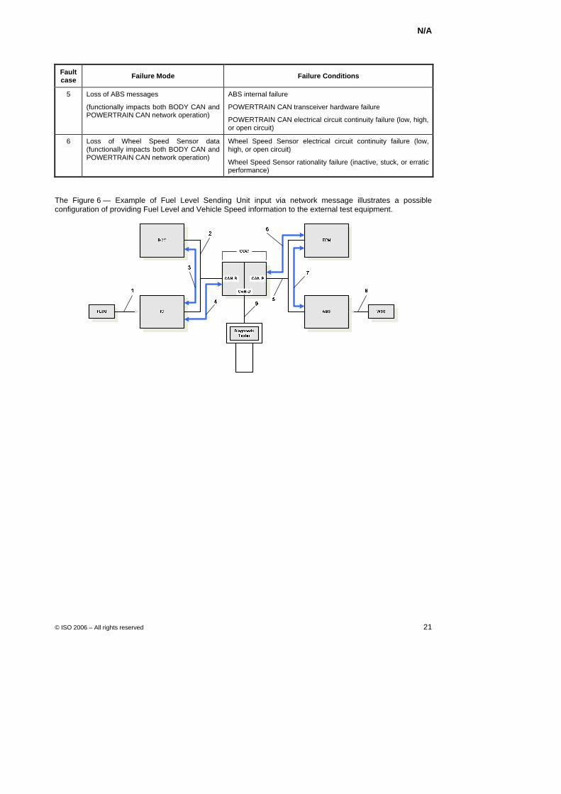
N/A
© ISO 2006 – All rights reserved 21
Fault case Failure Mode Failure Conditions
5 Loss of ABS messages
(functionally impacts both BODY CAN and POWERTRAIN CAN network operation)
ABS internal failure
POWERTRAIN CAN transceiver hardware failure
POWERTRAIN CAN electrical circuit continuity failure (low, high, or open circuit)
6 Loss of Wheel Speed Sensor data (functionally impacts both BODY CAN and POWERTRAIN CAN network operation)
Wheel Speed Sensor electrical circuit continuity failure (low, high, or open circuit)
Wheel Speed Sensor rationality failure (inactive, stuck, or erratic performance)
The Figure 6 — Example of Fuel Level Sending Unit input via network message illustrates a possible configuration of providing Fuel Level and Vehicle Speed information to the external test equipment.
Key
1 Fuel Level Sending Unit connected to Instrument Cluster via Body CAN (networked A/D read for ECM) 2 Body CAN bus 3 IC sends fuel level data to BCM 4 IC sends fuel level data to CGW 5 Powertrain CAN bus 6 ECM sends wheel speed data to CGW 7 ABS sends wheel speed data to ECM via Powertrain CAN bus 8 Wheel Speed Sensor connected to ABS via Powertrain CAN (networked Wheel Speed read for ECM) 9 Diagnostic CAN bus ABS Anti-lock Brake Control Module BCM Body Control Module CAN-B Body CAN CAN-P Powertrain CAN CAN-D Diagnostic CAN CGW Central Gateway ECM Engine Control Module FLSU Fuel Level Sending Unit IC Instrument Cluster WSS Wheel Speed Sensor
Figure 6 — Example of Fuel Level Sending Unit input via network message
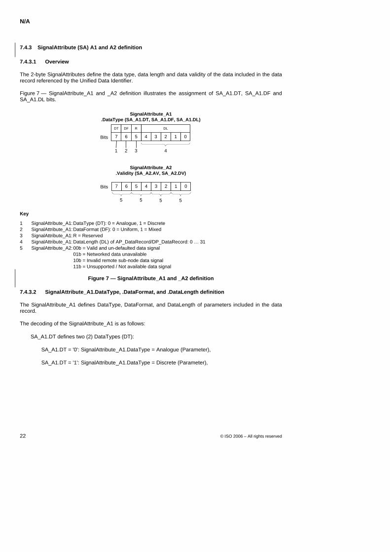
N/A
22 © ISO 2006 – All rights reserved
7.4.3 SignalAttribute (SA) A1 and A2 definition
7.4.3.1 Overview
The 2-byte SignalAttributes define the data type, data length and data validity of the data included in the data record referenced by the Unified Data Identifier.
Figure 7 — SignalAttribute_A1 and _A2 definition illustrates the assignment of SA_A1.DT, SA_A1.DF and SA_A1.DL bits.
67 45 23 01
SignalAttribute_A1.DataType (SA_A1.DT, SA_A1.DF, SA_A1.DL)
Bits
SignalAttribute_A2.Validity (SA_A2.AV, SA_A2.DV)
67 45 23 01
31 4
DT DL
5 5 5 5
Bits
DF R
2
Key
1 SignalAttribute_A1: DataType (DT): 0 = Analogue, 1 = Discrete 2 SignalAttribute_A1: DataFormat (DF): 0 = Uniform, 1 = Mixed 3 SignalAttribute_A1: R = Reserved 4 SignalAttribute_A1: DataLength (DL) of AP_DataRecord/DP_DataRecord: 0 … 31 5 SignalAttribute_A2: 00b = Valid and un-defaulted data signal 01b = Networked data unavailable 10b = Invalid remote sub-node data signal 11b = Unsupported / Not available data signal
Figure 7 — SignalAttribute_A1 and _A2 definition
7.4.3.2 SignalAttribute_A1.DataType, .DataFormat, and .DataLength definition
The SignalAttribute_A1 defines DataType, DataFormat, and DataLength of parameters included in the data record.
The decoding of the SignalAttribute_A1 is as follows:
SA_A1.DT defines two (2) DataTypes (DT):
SA_A1.DT = '0': SignalAttribute_A1.DataType = Analogue (Parameter),
SA_A1.DT = '1': SignalAttribute_A1.DataType = Discrete (Parameter),
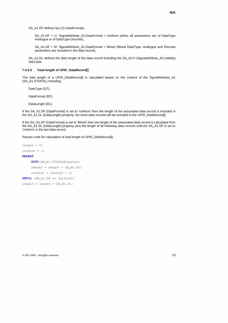
N/A
© ISO 2006 – All rights reserved 23
SA_A1.DF defines two (2) DataFormats:
SA_A1.DF = U: SignalAttribute_A1.DataFormat = Uniform (either all parameters are of DataType Analogue or of DataType Discrete),
SA_A1.DF = M: SignalAttribute_A1.DataFormat = Mixed (Mixed DataType, Analogue and Discrete parameters are included in the data record),
SA_A1.DL defines the data length of the data record including the SA_A2.V (SignalAttribute_A2.Validity) data byte.
7.4.3.3 Total length of UPID_DataRecord[]
The total length of a UPID_DataRecord[] is calculated based on the content of the SignalAttribute_A1 (SA_A1.DTDFDL) including:
DataType (DT),
DataFormat (DF),
DataLength (DL).
If the SA_A1.DF (DataFormat) is set to 'Uniform' then the length of the associated data record is included in the SA_A1.DL (DataLength) property. No more data records will be included in the UPID_DataRecord[].
If the SA_A1.DF (DataFormat) is set to 'Mixed' then the length of the associated data record is calculated from the SA_A1.DL (DataLength) property plus the length of all following data records until the SA_A1.DF is set to 'Uniform' in the last data record.
Pseudo code for calculation of total length of UPID_DataRecord[].
length = 0;
counter = 1;
REPEAT
GOTO SA_A1.DTDFDL#counter;
length = length + SA_A1.DL;
counter = counter + 1;
UNTIL (SA_A1.DF == Uniform);
length = length + SA_A1.DL;
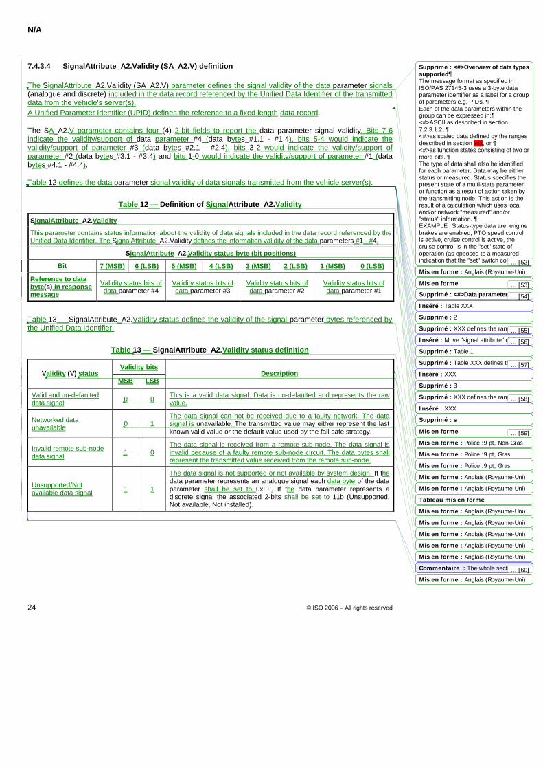
N/A
24 © ISO 2006 – All rights reserved
7.4.3.4 SignalAttribute_A2.Validity (SA_A2.V) definition
The SignalAttribute_A2.Validity (SA_A2.V) parameter defines the signal validity of the data parameter signals (analogue and discrete) included in the data record referenced by the Unified Data Identifier of the transmitted data from the vehicle's server(s). A Unified Parameter Identifier (UPID) defines the reference to a fixed length data record.
The SA_A2.V parameter contains four (4) 2-bit fields to report the data parameter signal validity. Bits 7-6 indicate the validity/support of data parameter #4 (data bytes #1.1 - #1.4), bits 5-4 would indicate the validity/support of parameter #3 (data bytes #2.1 - #2.4), bits 3-2 would indicate the validity/support of parameter #2 (data bytes #3.1 - #3.4) and bits 1-0 would indicate the validity/support of parameter #1 (data bytes #4.1 - #4.4).
Table 12 defines the data parameter signal validity of data signals transmitted from the vehicle server(s).
Table 12 — Definition of SignalAttribute_A2.Validity
SignalAttribute_A2.Validity
This parameter contains status information about the validity of data signals included in the data record referenced by the Unified Data Identifier. The SignalAttribute_A2.Validity defines the information validity of the data parameters #1 - #4.
SignalAttribute_A2.Validity status byte (bit positions)
Bit 7 (MSB) 6 (LSB) 5 (MSB) 4 (LSB) 3 (MSB) 2 (LSB) 1 (MSB) 0 (LSB)
Reference to data byte(s) in response message
Validity status bits of data parameter #4
Validity status bits of data parameter #3
Validity status bits of data parameter #2
Validity status bits of data parameter #1
Table 13 — SignalAttribute_A2.Validity status defines the validity of the signal parameter bytes referenced by the Unified Data Identifier.
Table 13 — SignalAttribute_A2.Validity status definition
Validity bits Validity (V) status
MSB LSB Description
Valid and un-defaulted data signal 0 0 This is a valid data signal. Data is un-defaulted and represents the raw
value.
Networked data unavailable 0 1
The data signal can not be received due to a faulty network. The data signal is unavailable. The transmitted value may either represent the last known valid value or the default value used by the fail-safe strategy.
Invalid remote sub-node data signal 1 0
The data signal is received from a remote sub-node. The data signal is invalid because of a faulty remote sub-node circuit. The data bytes shall represent the transmitted value received from the remote sub-node.
Unsupported/Not available data signal 1 1
The data signal is not supported or not available by system design. If the data parameter represents an analogue signal each data byte of the data parameter shall be set to 0xFF. If the data parameter represents a discrete signal the associated 2-bits shall be set to 11b (Unsupported, Not available, Not installed).
Mis en forme : Anglais (Royaume-Uni)
Mis en forme
Mis en forme : Anglais (Royaume-Uni)
Tableau mis en forme
Mis en forme : Anglais (Royaume-Uni)
Mis en forme : Police :9 pt, Gras
Mis en forme : Anglais (Royaume-Uni)
Mis en forme : Anglais (Royaume-Uni)
Mis en forme
Mis en forme : Anglais (Royaume-Uni)
Mis en forme : Police :9 pt, Non Gras
Mis en forme : Police :9 pt, Gras
Mis en forme : Anglais (Royaume-Uni)
Mis en forme : Anglais (Royaume-Uni)
Mis en forme : Anglais (Royaume-Uni)
Supprimé : <#>Overview of data types supported¶The message format as specified in ISO/PAS 27145-3 uses a 3-byte data parameter identifier as a label for a group of parameters e.g. PIDs. ¶Each of the data parameters within the group can be expressed in:¶<#>ASCII as described in section 7.2.3.1.2, ¶<#>as scaled data defined by the ranges described in section xxx, or ¶<#>as function states consisting of two or more bits. ¶The type of data shall also be identified for each parameter. Data may be either status or measured. Status specifies the present state of a multi-state parameter or function as a result of action taken by the transmitting node. This action is the result of a calculation which uses local and/or network "measured" and/or "status" information. ¶EXAMPLE Status-type data are: engine brakes are enabled, PTO speed control is active, cruise control is active, the cruise control is in the "set" state of operation (as opposed to a measured indication that the "set" switch contacts are closed), diagnostic trouble codes,
Supprimé : <#>Data parameter ranges¶Move "signal attribute" definition from Inséré : Table XXX
Supprimé : 2
Supprimé : XXX defines the ranges used to denote the state of a discrete Inséré : Move "signal attribute" definition from ISO27145-3 to this document and Supprimé : Table 1
Supprimé : Table XXX defines the ranges used to determine the validity of a Inséré : XXX
Supprimé : 3
Supprimé : XXX defines the ranges used to denote the state of a control Inséré : XXX
Supprimé : s
Commentaire : The whole section may be moved to ISO/PAS27145-2 as it
... [56]
... [54]
... [53]
... [57]
... [58]
... [55]
... [52]
... [60]
... [59]
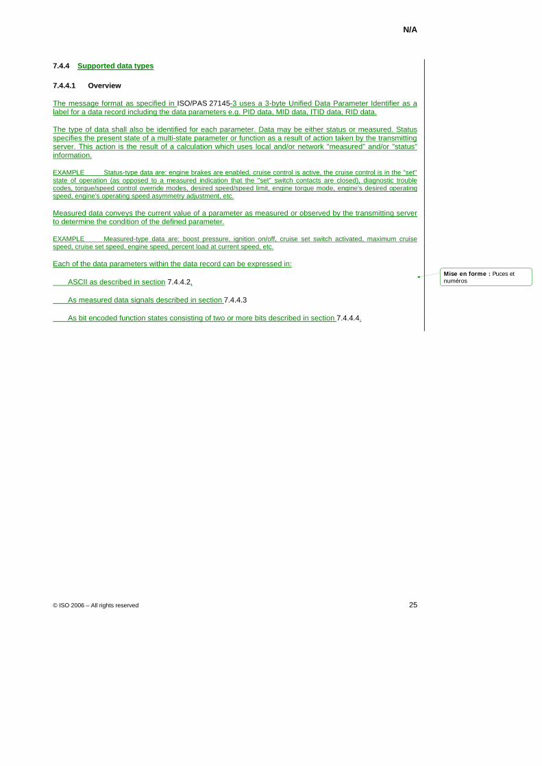
N/A
© ISO 2006 – All rights reserved 25
7.4.4 Supported data types
7.4.4.1 Overview
The message format as specified in ISO/PAS 27145-3 uses a 3-byte Unified Data Parameter Identifier as a label for a data record including the data parameters e.g. PID data, MID data, ITID data, RID data.
The type of data shall also be identified for each parameter. Data may be either status or measured. Status specifies the present state of a multi-state parameter or function as a result of action taken by the transmitting server. This action is the result of a calculation which uses local and/or network "measured" and/or "status" information.
EXAMPLE Status-type data are: engine brakes are enabled, cruise control is active, the cruise control is in the "set" state of operation (as opposed to a measured indication that the "set" switch contacts are closed), diagnostic trouble codes, torque/speed control override modes, desired speed/speed limit, engine torque mode, engine's desired operating speed, engine's operating speed asymmetry adjustment, etc.
Measured data conveys the current value of a parameter as measured or observed by the transmitting server to determine the condition of the defined parameter.
EXAMPLE Measured-type data are: boost pressure, ignition on/off, cruise set switch activated, maximum cruise speed, cruise set speed, engine speed, percent load at current speed, etc.
Each of the data parameters within the data record can be expressed in:
ASCII as described in section 7.4.4.2,
As measured data signals described in section 7.4.4.3
As bit encoded function states consisting of two or more bits described in section 7.4.4.4.
Mise en forme : Puces etnuméros
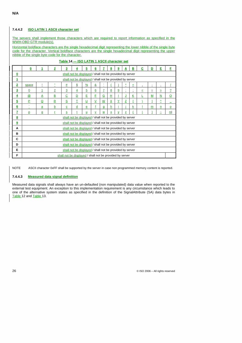
N/A
26 © ISO 2006 – All rights reserved
7.4.4.2 ISO LATIN 1 ASCII character set
The servers shall implement those characters which are required to report information as specified in the WWH-OBD GTR module(s).
Horizontal boldface characters are the single hexadecimal digit representing the lower nibble of the single byte code for the character. Vertical boldface characters are the single hexadecimal digit representing the upper nibble of the single byte code for the character.
Table 14 — ISO LATIN 1 ASCII character set
0 1 2 3 4 5 6 7 8 9 A B C D E F
0 shall not be displayed / shall not be provided by server
1 shall not be displayed / shall not be provided by server
2 space ! " # $ % & ' ( ) * + , - . /
3 0 1 2 3 4 5 6 7 8 9 : ; < = > ?
4 @ A B C D E F G H I J K L M N O
5 P Q R S T U V W X Y Z [ \ ] ^ _
6 ` a b c d e f g h i j k l m n o
7 p q r s t u v w x y z | ~ nil
8 shall not be displayed / shall not be provided by server
9 shall not be displayed / shall not be provided by server
A shall not be displayed / shall not be provided by server
B shall not be displayed / shall not be provided by server
C shall not be displayed / shall not be provided by server
D shall not be displayed / shall not be provided by server
E shall not be displayed / shall not be provided by server
F shall not be displayed / shall not be provided by server
NOTE ASCII character 0xFF shall be supported by the server in case non programmed memory content is reported.
7.4.4.3 Measured data signal definition
Measured data signals shall always have an un-defaulted (non manipulated) data value when reported to the external test equipment. An exception to this implementation requirement is any circumstance which leads to one of the alternative system states as specified in the definition of the SignalAttribute (SA) data bytes in Table 12 and Table 13.
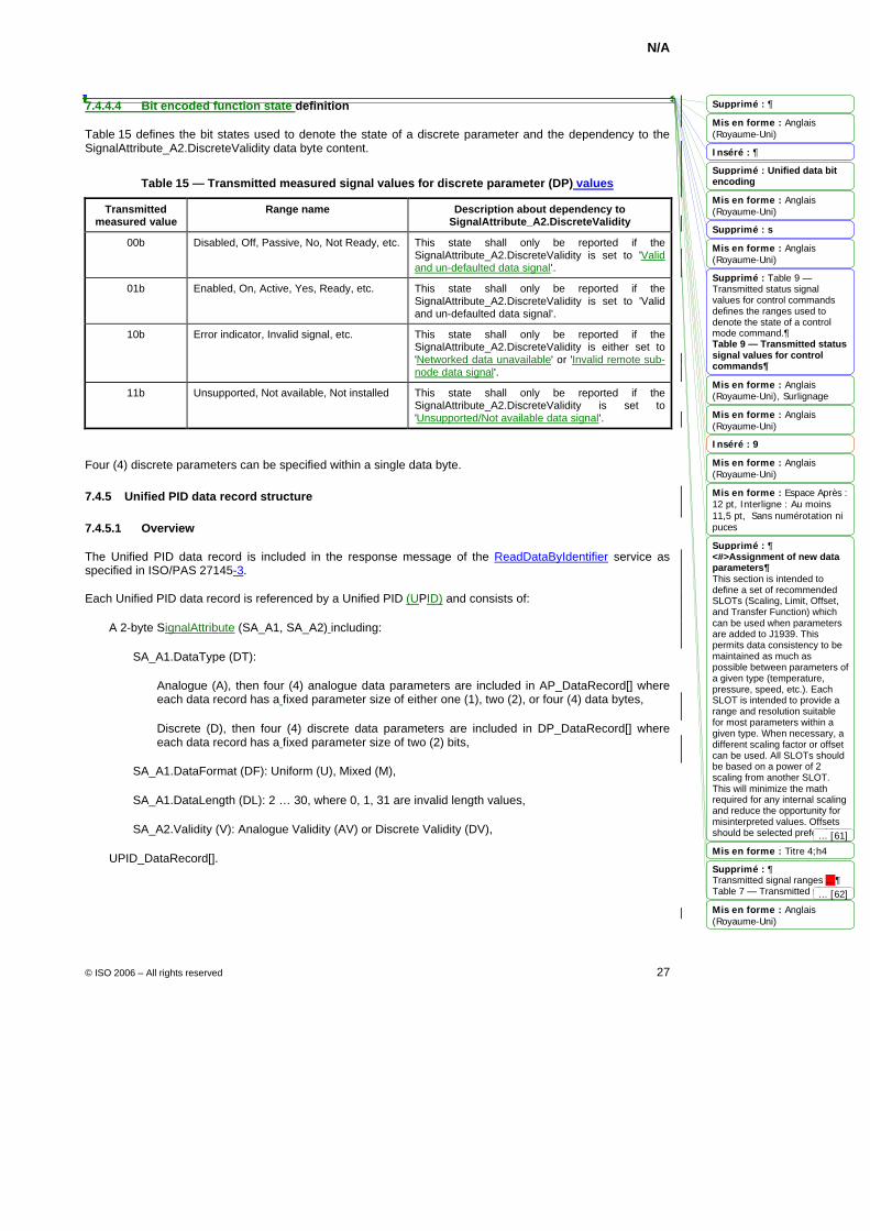
N/A
© ISO 2006 – All rights reserved 27
7.4.4.4 Bit encoded function state definition
Table 15 defines the bit states used to denote the state of a discrete parameter and the dependency to the SignalAttribute_A2.DiscreteValidity data byte content.
Table 15 — Transmitted measured signal values for discrete parameter (DP) values
Transmitted measured value
Range name Description about dependency to SignalAttribute_A2.DiscreteValidity
00b Disabled, Off, Passive, No, Not Ready, etc. This state shall only be reported if the SignalAttribute_A2.DiscreteValidity is set to 'Valid and un-defaulted data signal'.
01b Enabled, On, Active, Yes, Ready, etc. This state shall only be reported if the SignalAttribute_A2.DiscreteValidity is set to 'Valid and un-defaulted data signal'.
10b Error indicator, Invalid signal, etc. This state shall only be reported if the SignalAttribute_A2.DiscreteValidity is either set to 'Networked data unavailable' or 'Invalid remote sub-node data signal'.
11b Unsupported, Not available, Not installed This state shall only be reported if the SignalAttribute_A2.DiscreteValidity is set to 'Unsupported/Not available data signal'.
Four (4) discrete parameters can be specified within a single data byte.
7.4.5 Unified PID data record structure
7.4.5.1 Overview
The Unified PID data record is included in the response message of the ReadDataByIdentifier service as specified in ISO/PAS 27145-3.
Each Unified PID data record is referenced by a Unified PID (UPID) and consists of:
A 2-byte SignalAttribute (SA_A1, SA_A2) including:
SA_A1.DataType (DT):
Analogue (A), then four (4) analogue data parameters are included in AP_DataRecord[] where each data record has a fixed parameter size of either one (1), two (2), or four (4) data bytes,
Discrete (D), then four (4) discrete data parameters are included in DP_DataRecord[] where each data record has a fixed parameter size of two (2) bits,
SA_A1.DataFormat (DF): Uniform (U), Mixed (M),
SA_A1.DataLength (DL): 2 … 30, where 0, 1, 31 are invalid length values,
SA_A2.Validity (V): Analogue Validity (AV) or Discrete Validity (DV),
UPID_DataRecord[].
Mis en forme : Anglais(Royaume-Uni)
Mis en forme : Anglais(Royaume-Uni)
Mis en forme : Anglais(Royaume-Uni)
Mis en forme : Anglais(Royaume-Uni), Surlignage
Mis en forme : Anglais(Royaume-Uni)
Mis en forme : Anglais(Royaume-Uni)
Mis en forme : Espace Après :12 pt, Interligne : Au moins11,5 pt, Sans numérotation nipuces
Mis en forme : Titre 4;h4
Mis en forme : Anglais(Royaume-Uni)
Supprimé : 
Inséré : 
Supprimé : Unified data bit encoding
Supprimé : s
Supprimé : Table 9 — Transmitted status signal values for control commands defines the ranges used to denote the state of a control mode command.¶Table 9 — Transmitted status signal values for control commands
Inséré : 9
Supprimé : ¶<#>Assignment of new data parameters¶This section is intended to define a set of recommended SLOTs (Scaling, Limit, Offset, and Transfer Function) which can be used when parameters are added to J1939. This permits data consistency to be maintained as much as possible between parameters of a given type (temperature, pressure, speed, etc.). Each SLOT is intended to provide a range and resolution suitable for most parameters within a given type. When necessary, a different scaling factor or offset can be used. All SLOTs should be based on a power of 2 scaling from another SLOT. This will minimize the math required for any internal scaling and reduce the opportunity for misinterpreted values. Offsets should be selected preferably on the following basis:
Supprimé : ¶Transmitted signal ranges …¶Table 7 — Transmitted signal ranges
... [61]
... [62]
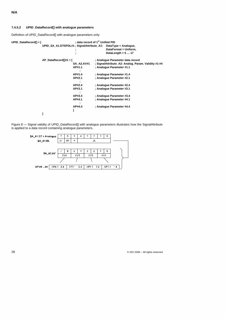
N/A
28 © ISO 2006 – All rights reserved
7.4.5.2 UPID_DataRecord[] with analogue parameters
Definition of UPID_DataRecord[] with analogue parameters only:
UPID_DataRecord[] = [ ; data record of 1st Unified PID UPID_SA_A1.DTDFDL#1 ; SignalAttribute_A1: DataType = Analogue,
; DataFormat = Uniform, ; DataLength = 5 … 17
AP_DataRecord[]#1 = [ ; Analogue Parameter data record
SA_A2.AV#1 ; SignalAttribute_A2: Analog. Param. Validity #1-#4 AP#1.1 ; Analogue Parameter #1.1 : AP#1.4 ; Analogue Parameter #1.4 AP#2.1 ; Analogue Parameter #2.1 : AP#2.4 ; Analogue Parameter #2.4 AP#3.1 ; Analogue Parameter #3.1 : AP#3.4 ; Analogue Parameter #3.4 AP#4.1 ; Analogue Parameter #4.1 : AP#4.4 ; Analogue Parameter #4.4 ]
]
Figure 8 — Signal validity of UPID_DataRecord[] with analogue parameters illustrates how the SignalAttribute is applied to a data record containing analogue parameters.
Key
SA_A1.DTDFDL SignalAttribute_A1: DataType, DataFormat, DataLength R Reserved SA_A2.AV SignalAttribute_A2: AnalogueValidity AP AnalogueParameter
Figure 8 — Signal validity of UPID_DataRecord[] with analogue parameters
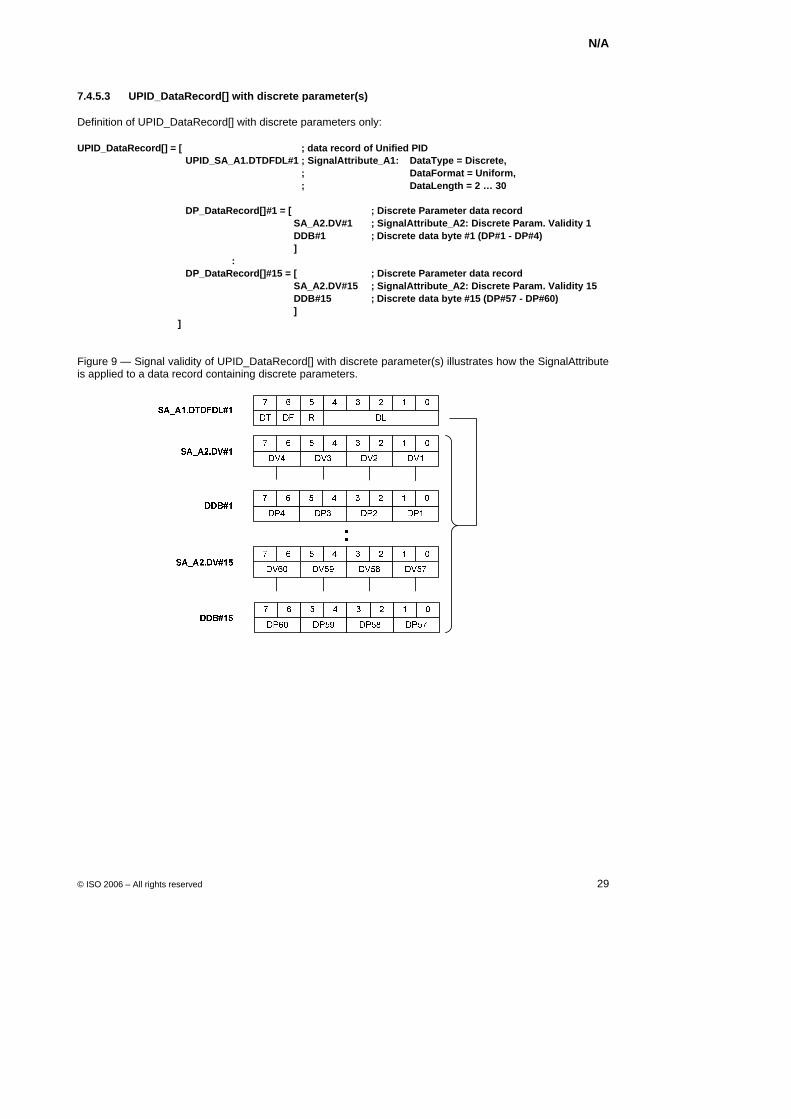
N/A
© ISO 2006 – All rights reserved 29
7.4.5.3 UPID_DataRecord[] with discrete parameter(s)
Definition of UPID_DataRecord[] with discrete parameters only:
UPID_DataRecord[] = [ ; data record of Unified PID UPID_SA_A1.DTDFDL#1 ; SignalAttribute_A1: DataType = Discrete,
; DataFormat = Uniform, ; DataLength = 2 … 30
DP_DataRecord[]#1 = [ ; Discrete Parameter data record
SA_A2.DV#1 ; SignalAttribute_A2: Discrete Param. Validity 1 DDB#1 ; Discrete data byte #1 (DP#1 - DP#4) ]
: DP_DataRecord[]#15 = [ ; Discrete Parameter data record
SA_A2.DV#15 ; SignalAttribute_A2: Discrete Param. Validity 15 DDB#15 ; Discrete data byte #15 (DP#57 - DP#60) ]
]
Figure 9 — Signal validity of UPID_DataRecord[] with discrete parameter(s) illustrates how the SignalAttribute is applied to a data record containing discrete parameters.
Key
SA_A1.DTDFDL SignalAttribute_A1: DataType, DataFormat, DataLength R Reserved SA_A2.DV SignalAttribute_A2: DiscreteValidity DDB Discrete Data Byte DP DiscreteParameter
Figure 9 — Signal validity of UPID_DataRecord[] with discrete parameter(s)
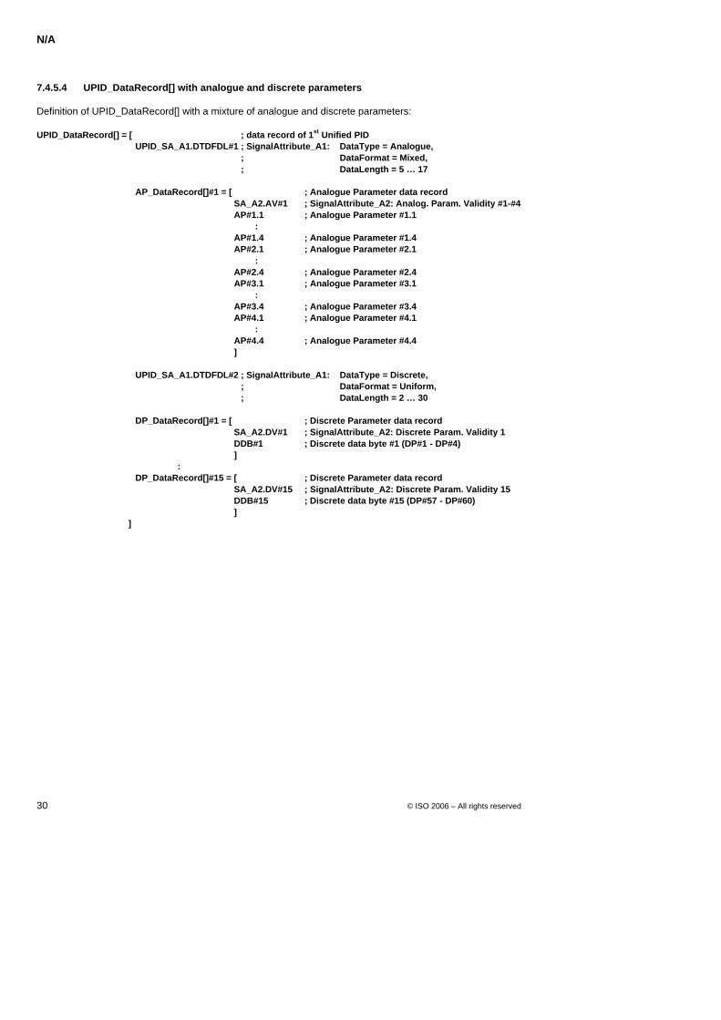
N/A
30 © ISO 2006 – All rights reserved
7.4.5.4 UPID_DataRecord[] with analogue and discrete parameters
Definition of UPID_DataRecord[] with a mixture of analogue and discrete parameters:
UPID_DataRecord[] = [ ; data record of 1st Unified PID UPID_SA_A1.DTDFDL#1 ; SignalAttribute_A1: DataType = Analogue,
; DataFormat = Mixed, ; DataLength = 5 … 17
AP_DataRecord[]#1 = [ ; Analogue Parameter data record
SA_A2.AV#1 ; SignalAttribute_A2: Analog. Param. Validity #1-#4 AP#1.1 ; Analogue Parameter #1.1 : AP#1.4 ; Analogue Parameter #1.4 AP#2.1 ; Analogue Parameter #2.1 : AP#2.4 ; Analogue Parameter #2.4 AP#3.1 ; Analogue Parameter #3.1 : AP#3.4 ; Analogue Parameter #3.4 AP#4.1 ; Analogue Parameter #4.1 : AP#4.4 ; Analogue Parameter #4.4 ]
UPID_SA_A1.DTDFDL#2 ; SignalAttribute_A1: DataType = Discrete,
; DataFormat = Uniform, ; DataLength = 2 … 30
DP_DataRecord[]#1 = [ ; Discrete Parameter data record
SA_A2.DV#1 ; SignalAttribute_A2: Discrete Param. Validity 1 DDB#1 ; Discrete data byte #1 (DP#1 - DP#4) ]
: DP_DataRecord[]#15 = [ ; Discrete Parameter data record
SA_A2.DV#15 ; SignalAttribute_A2: Discrete Param. Validity 15 DDB#15 ; Discrete data byte #15 (DP#57 - DP#60) ]
]
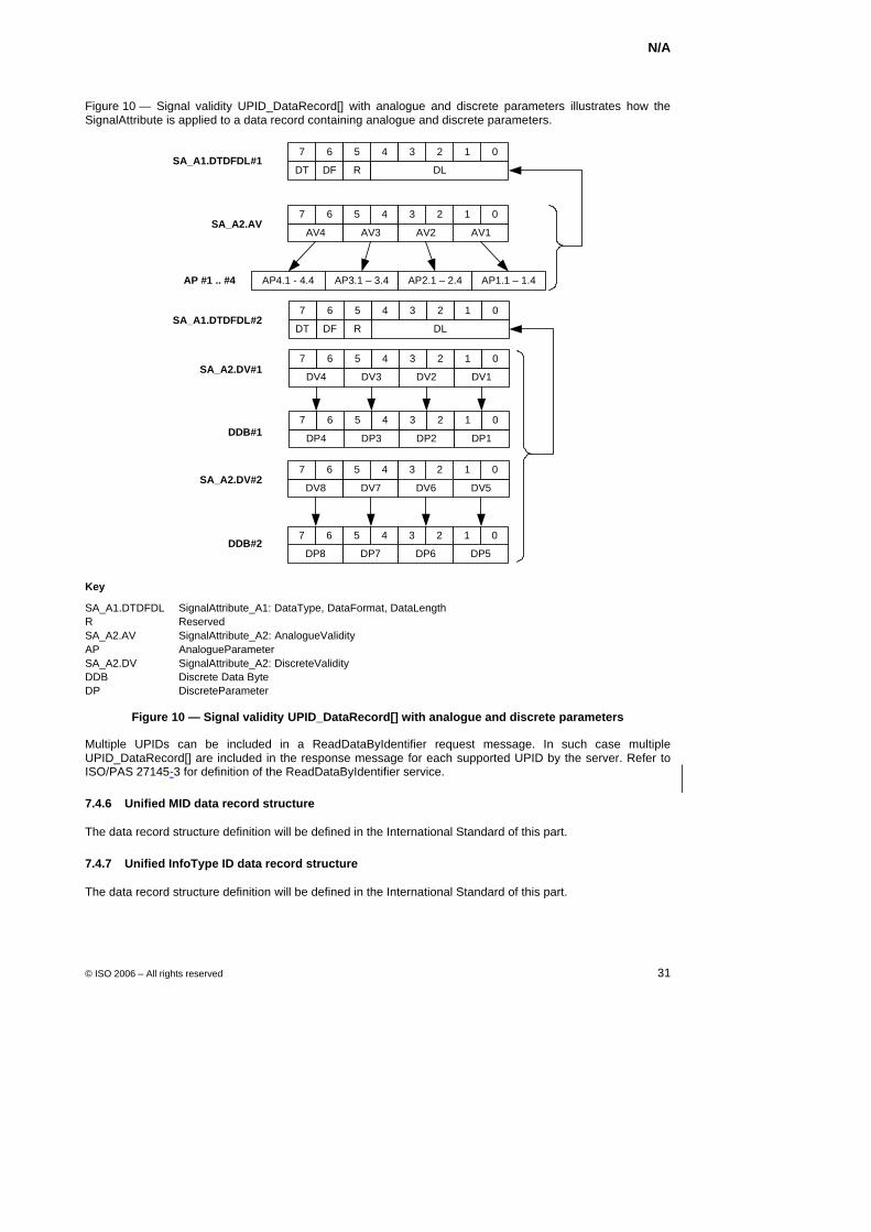
N/A
© ISO 2006 – All rights reserved 31
Figure 10 — Signal validity UPID_DataRecord[] with analogue and discrete parameters illustrates how the SignalAttribute is applied to a data record containing analogue and discrete parameters.
DFDT R DL
67 45 0123
AV4 AV3 AV1
67 45 0123
AV2SA_A2.AV
AP4.1 - 4.4 AP3.1 – 3.4 AP1.1 – 1.4AP2.1 – 2.4AP #1 .. #4
DFDT R DL
67 45 0123
DV4 DV3 DV1
67 45 0123
DV2
DP4 DP3 DP1DP2
DV8 DV7 DV5
67 45 0123
DV6
DP8 DP7 DP5DP6
SA_A1.DTDFDL#1
DDB#1
SA_A2.DV#1
DDB#2
SA_A2.DV#2
SA_A1.DTDFDL#2
67 45 0123
67 45 0123
Key
SA_A1.DTDFDL SignalAttribute_A1: DataType, DataFormat, DataLength R Reserved SA_A2.AV SignalAttribute_A2: AnalogueValidity AP AnalogueParameter SA_A2.DV SignalAttribute_A2: DiscreteValidity DDB Discrete Data Byte DP DiscreteParameter
Figure 10 — Signal validity UPID_DataRecord[] with analogue and discrete parameters
Multiple UPIDs can be included in a ReadDataByIdentifier request message. In such case multiple UPID_DataRecord[] are included in the response message for each supported UPID by the server. Refer to ISO/PAS 27145-3 for definition of the ReadDataByIdentifier service.
7.4.6 Unified MID data record structure
The data record structure definition will be defined in the International Standard of this part.
7.4.7 Unified InfoType ID data record structure
The data record structure definition will be defined in the International Standard of this part.
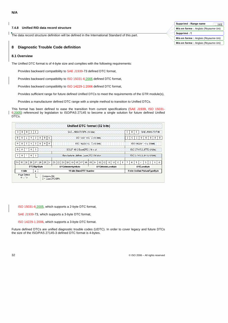
N/A
32 © ISO 2006 – All rights reserved
7.4.8 Unified RID data record structure
The data record structure definition will be defined in the International Standard of this part.
8 Diagnostic Trouble Code definition
8.1 Overview
The Unified DTC format is of 4-byte size and complies with the following requirements:
Provides backward compatibility to SAE J1939-73 defined DTC format,
Provides backward compatibility to ISO 15031-6:2005 defined DTC format,
Provides backward compatibility to ISO 14229-1:2006 defined DTC format,
Provides sufficient range for future defined Unified DTCs to meet the requirements of the GTR module(s),
Provides a manufacturer defined DTC range with a simple method to transition to Unified DTCs.
This format has been defined to ease the transition from current specifications (SAE J1939, ISO 15031-6:2005) referenced by legislation to ISO/PAS 27145 to become a single solution for future defined Unified DTCs.
Figure 11 — ISO 27145-2 Unified DTC format
ISO/PAS 27145-3 defines a 4-byte diagnostic trouble code format in order to provide backward compatibility to:
ISO 15031-6:2005, which supports a 2-byte DTC format,
SAE J1939-73, which supports a 3-byte DTC format,
ISO 14229-1:2006, which supports a 3-byte DTC format.
Future defined DTCs are unified diagnostic trouble codes (UDTC). In order to cover legacy and future DTCs the size of the ISO/PAS 27145-3 defined DTC format is 4-bytes.
Mis en forme : Anglais (Royaume-Uni)
Mis en forme : Anglais (Royaume-Uni)
Mis en forme : Anglais (Royaume-Uni)
Supprimé : Range name
Supprimé : 
... [63]
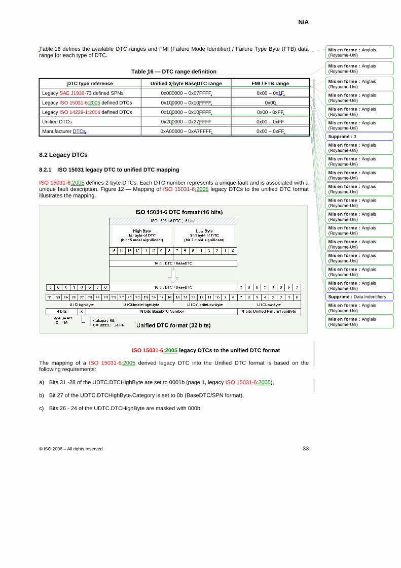
N/A
© ISO 2006 – All rights reserved 33
Table 16 defines the available DTC ranges and FMI (Failure Mode Identifier) / Failure Type Byte (FTB) data range for each type of DTC.
Table 16 — DTC range definition
DTC type reference Unified 3-byte BaseDTC range FMI / FTB range
Legacy SAE J1939-73 defined SPNs 0x000000 – 0x07FFFF 0x00 – 0x1F
Legacy ISO 15031-6:2005 defined DTCs 0x100000 – 0x10FFFF 0x00
Legacy ISO 14229-1:2006 defined DTCs 0x100000 – 0x10FFFF 0x00 - 0xFF
Unified DTCs 0x200000 – 0x27FFFF 0x00 – 0xFF
Manufacturer DTCs 0xA00000 – 0xA7FFFF 0x00 – 0xFF
8.2 Legacy DTCs
8.2.1 ISO 15031 legacy DTC to unified DTC mapping
ISO 15031-6:2005 defines 2-byte DTCs. Each DTC number represents a unique fault and is associated with a unique fault description. Figure 12 — Mapping of ISO 15031-6:2005 legacy DTCs to the unified DTC format illustrates the mapping.
Figure 12 — Mapping of ISO 15031-6:2005 legacy DTCs to the unified DTC format
The mapping of a ISO 15031-6:2005 derived legacy DTC into the Unified DTC format is based on the following requirements:
a) Bits 31 -28 of the UDTC.DTCHighByte are set to 0001b (page 1, legacy ISO 15031-6:2005),
b) Bit 27 of the UDTC.DTCHighByte.Category is set to 0b (BaseDTC/SPN format),
c) Bits 26 - 24 of the UDTC.DTCHighByte are masked with 000b,
Mis en forme : Anglais(Royaume-Uni)
Mis en forme : Anglais(Royaume-Uni)
Mis en forme : Anglais(Royaume-Uni)
Mis en forme : Anglais(Royaume-Uni)
Mis en forme : Anglais(Royaume-Uni)
Mis en forme : Anglais(Royaume-Uni)
Mis en forme : Anglais(Royaume-Uni)
Mis en forme : Anglais(Royaume-Uni)
Mis en forme : Anglais(Royaume-Uni)
Mis en forme : Anglais(Royaume-Uni)
Mis en forme : Anglais(Royaume-Uni)
Mis en forme : Anglais(Royaume-Uni)
Mis en forme : Anglais(Royaume-Uni)
Mis en forme : Anglais(Royaume-Uni)
Mis en forme : Anglais(Royaume-Uni)
Mis en forme : Anglais(Royaume-Uni)
Mis en forme : Anglais(Royaume-Uni)
Mis en forme : Anglais(Royaume-Uni)
Mis en forme : Anglais(Royaume-Uni)
Supprimé : 3
Supprimé : Data Indentifiers
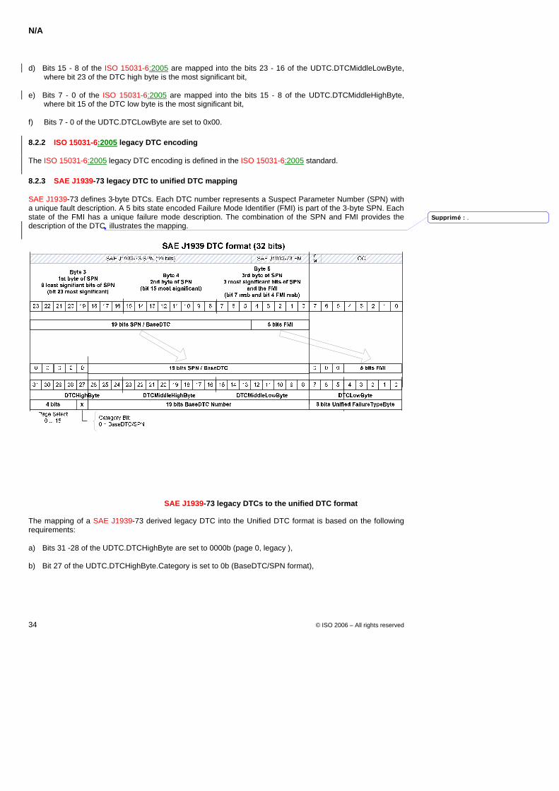
N/A
34 © ISO 2006 – All rights reserved
d) Bits 15 - 8 of the ISO 15031-6:2005 are mapped into the bits 23 - 16 of the UDTC.DTCMiddleLowByte, where bit 23 of the DTC high byte is the most significant bit,
e) Bits 7 - 0 of the ISO 15031-6:2005 are mapped into the bits 15 - 8 of the UDTC.DTCMiddleHighByte, where bit 15 of the DTC low byte is the most significant bit,
f) Bits 7 - 0 of the UDTC.DTCLowByte are set to 0x00.
8.2.2 ISO 15031-6:2005 legacy DTC encoding
The ISO 15031-6:2005 legacy DTC encoding is defined in the ISO 15031-6:2005 standard.
8.2.3 SAE J1939-73 legacy DTC to unified DTC mapping
SAE J1939-73 defines 3-byte DTCs. Each DTC number represents a Suspect Parameter Number (SPN) with a unique fault description. A 5 bits state encoded Failure Mode Identifier (FMI) is part of the 3-byte SPN. Each state of the FMI has a unique failure mode description. The combination of the SPN and FMI provides the description of the DTC illustrates the mapping.
Key
SPN Suspect Parameter Number FMI Failure Mode Identifier CM Conversion method OC Occurrence count
Figure 13 — Mapping of SAE J1939-73 legacy DTCs to the unified DTC format
The mapping of a SAE J1939-73 derived legacy DTC into the Unified DTC format is based on the following requirements:
a) Bits 31 -28 of the UDTC.DTCHighByte are set to 0000b (page 0, legacy ),
b) Bit 27 of the UDTC.DTCHighByte.Category is set to 0b (BaseDTC/SPN format),
Supprimé : .
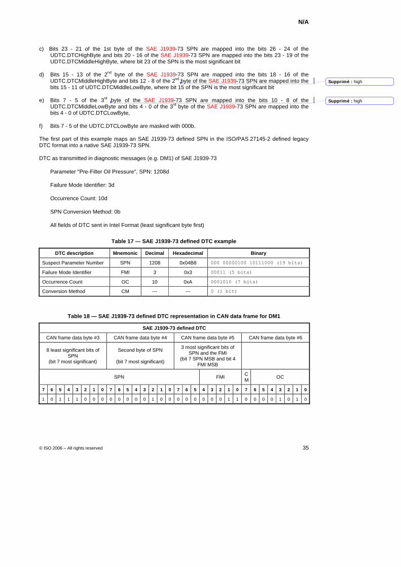
N/A
© ISO 2006 – All rights reserved 35
c) Bits 23 - 21 of the 1st byte of the SAE J1939-73 SPN are mapped into the bits 26 - 24 of the UDTC.DTCHighByte and bits 20 - 16 of the SAE J1939-73 SPN are mapped into the bits 23 - 19 of the UDTC.DTCMiddleHighByte, where bit 23 of the SPN is the most significant bit
d) Bits 15 - 13 of the 2nd byte of the SAE J1939-73 SPN are mapped into the bits 18 - 16 of the UDTC.DTCMiddleHighByte and bits 12 - 8 of the 2nd byte of the SAE J1939-73 SPN are mapped into the bits 15 - 11 of UDTC.DTCMiddleLowByte, where bit 15 of the SPN is the most significant bit
e) Bits 7 - 5 of the 3rd byte of the SAE J1939-73 SPN are mapped into the bits 10 - 8 of the UDTC.DTCMiddleLowByte and bits 4 - 0 of the 3rd byte of the SAE J1939-73 SPN are mapped into the bits 4 - 0 of UDTC.DTCLowByte,
f) Bits 7 - 5 of the UDTC.DTCLowByte are masked with 000b.
The first part of this example maps an SAE J1939-73 defined SPN in the ISO/PAS 27145-2 defined legacy DTC format into a native SAE J1939-73 SPN.
DTC as transmitted in diagnostic messages (e.g. DM1) of SAE J1939-73
Parameter "Pre-Filter Oil Pressure", SPN: 1208d
Failure Mode Identifier: 3d
Occurrence Count: 10d
SPN Conversion Method: 0b
All fields of DTC sent in Intel Format (least significant byte first)
Table 17 — SAE J1939-73 defined DTC example
DTC description Mnemonic Decimal Hexadecimal Binary
Suspect Parameter Number SPN 1208 0x04B8 000 00000100 10111000 (19 bits)
Failure Mode Identifier FMI 3 0x3 00011 (5 bits)
Occurrence Count OC 10 0xA 0001010 (7 bits)
Conversion Method CM --- --- 0 (1 bit)
Table 18 — SAE J1939-73 defined DTC representation in CAN data frame for DM1
SAE J1939-73 defined DTC
CAN frame data byte #3 CAN frame data byte #4 CAN frame data byte #5 CAN frame data byte #6
8 least significant bits of SPN
(bit 7 most significant)
Second byte of SPN
(bit 7 most significant)
3 most significant bits of SPN and the FMI
(bit 7 SPN MSB and bit 4 FMI MSB
SPN FMI CM OC
7 6 5 4 3 2 1 0 7 6 5 4 3 2 1 0 7 6 5 4 3 2 1 0 7 6 5 4 3 2 1 0
1 0 1 1 1 0 0 0 0 0 0 0 0 1 0 0 0 0 0 0 0 0 1 1 0 0 0 0 1 0 1 0
Supprimé : high
Supprimé : high
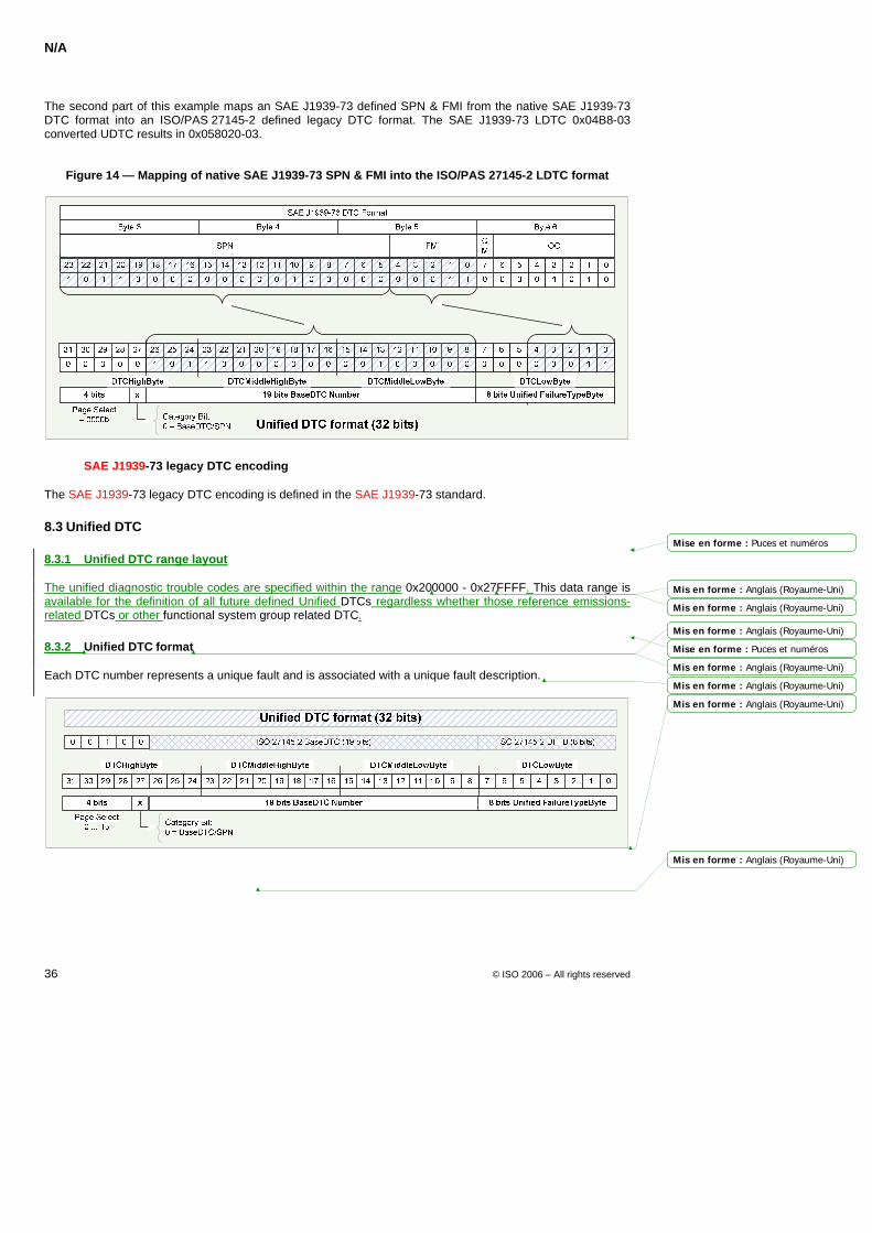
N/A
36 © ISO 2006 – All rights reserved
The second part of this example maps an SAE J1939-73 defined SPN & FMI from the native SAE J1939-73 DTC format into an ISO/PAS 27145-2 defined legacy DTC format. The SAE J1939-73 LDTC 0x04B8-03 converted UDTC results in 0x058020-03.
Figure 14 — Mapping of native SAE J1939-73 SPN & FMI into the ISO/PAS 27145-2 LDTC format
8.2.4 SAE J1939-73 legacy DTC encoding
The SAE J1939-73 legacy DTC encoding is defined in the SAE J1939-73 standard.
8.3 Unified DTC
8.3.1 Unified DTC range layout
The unified diagnostic trouble codes are specified within the range 0x200000 - 0x27FFFF. This data range is available for the definition of all future defined Unified DTCs regardless whether those reference emissions-related DTCs or other functional system group related DTC.
8.3.2 Unified DTC format
Each DTC number represents a unique fault and is associated with a unique fault description.
Figure 15 — Unified DTC format definition
Mise en forme : Puces et numéros
Mis en forme : Anglais (Royaume-Uni)
Mis en forme : Anglais (Royaume-Uni)
Mis en forme : Anglais (Royaume-Uni)
Mise en forme : Puces et numéros
Mis en forme : Anglais (Royaume-Uni)
Mis en forme : Anglais (Royaume-Uni)
Mis en forme : Anglais (Royaume-Uni)
Mis en forme : Anglais (Royaume-Uni)
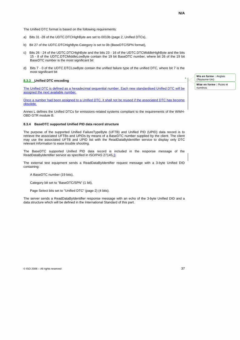
N/A
© ISO 2006 – All rights reserved 37
The Unified DTC format is based on the following requirements:
a) Bits 31 -28 of the UDTC.DTCHighByte are set to 0010b (page 2, Unified DTCs),
b) Bit 27 of the UDTC.DTCHighByte.Category is set to 0b (BaseDTC/SPN format),
c) Bits 26 - 24 of the UDTC.DTCHighByte and the bits 23 - 16 of the UDTC.DTCMiddleHighByte and the bits 15 - 8 of the UDTC.DTCMiddleLowByte contain the 19 bit BaseDTC number, where bit 26 of the 19 bit BaseDTC number is the most significant bit
d) Bits 7 - 0 of the UDTC.DTCLowByte contain the unified failure type of the unified DTC, where bit 7 is the most significant bit
8.3.3 Unified DTC encoding
The Unified DTC is defined as a hexadecimal sequential number. Each new standardised Unified DTC will be assigned the next available number.
Once a number had been assigned to a Unified DTC, it shall not be reused if the associated DTC has become obsolete.
Annex L defines the Unified DTCs for emissions-related systems compliant to the requirements of the WWH-OBD GTR module B.
8.3.4 BaseDTC supported Unified PID data record structure
The purpose of the supported Unified FailureTypeByte (UFTB) and Unified PID (UPID) data record is to retrieve the associated UFTBs and UPIDs by means of a BaseDTC number supplied by the client. The client may use the associated UFTB and UPID list with the ReadDataByIdentifier service to display only DTC relevant information to ease trouble shooting.
The BaseDTC supported Unified PID data record is included in the response message of the ReadDataByIdentifier service as specified in ISO/PAS 27145-3.
The external test equipment sends a ReadDataByIdentifier request message with a 3-byte Unified DID containing:
A BaseDTC number (19 bits),
Category bit set to "BaseDTC/SPN" (1 bit),
Page Select bits set to "Unified DTC" (page 2) (4 bits).
The server sends a ReadDataByIdentifier response message with an echo of the 3-byte Unified DID and a data structure which will be defined in the International Standard of this part.
Mis en forme : Anglais(Royaume-Uni)
Mise en forme : Puces etnuméros
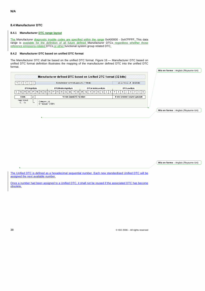
N/A
38 © ISO 2006 – All rights reserved
8.4 Manufacturer DTC
8.4.1 Manufacturer DTC range layout
The Manufacturer diagnostic trouble codes are specified within the range 0xA00000 - 0xA7FFFF. This data range is available for the definition of all future defined Manufacturer DTCs regardless whether those reference emissions-related DTCs or other functional system group related DTC.
8.4.2 Manufacturer DTC based on unified DTC format
The Manufacturer DTC shall be based on the unified DTC format. Figure 16 — Manufacturer DTC based on unified DTC format definition illustrates the mapping of the manufacturer defined DTC into the unified DTC format.
Figure 16 — Manufacturer DTC based on unified DTC format definition
The Manufacturer DTC shall be based on the unified DTC format and meets the following requirements:
a) Bits 31 -28 of the UDTC.DTCHighByte are set to 1010b (page 10, Manufacturer defined DTCs),
b) Bit 27 of the UDTC.DTCHighByte.Category is set to 0b (BaseDTC/SPN format),
c) Bits 26 - 24 of the UDTC.DTCHighByte and the bits 23 - 16 of the UDTC.DTCMiddleHighByte and the bits 15 - 8 of the UDTC.DTCMiddleLowByte contain the 19 bit BaseDTC number, where bit 26 of the 19 bit BaseDTC number is the most significant bit
d) Bits 7 - 0 of the UDTC.DTCLowByte contain the unified failure type of the unified DTC, where bit 7 is the most significant bit
8.4.3 Manufacturer DTC encoding
The Unified DTC is defined as a hexadecimal sequential number. Each new standardised Unified DTC will be assigned the next available number.
Once a number had been assigned to a Unified DTC, it shall not be reused if the associated DTC has become obsolete.
Mis en forme : Anglais (Royaume-Uni)
Mis en forme : Anglais (Royaume-Uni)
Mis en forme : Anglais (Royaume-Uni)
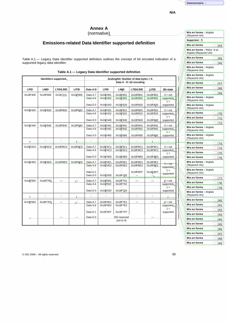
N/A
© ISO 2006 – All rights reserved 39
Annex A (normative)
Emissions-related Data Identifier supported definition
Table A.1 — Legacy Data Identifier supported definition outlines the concept of bit encoded indication of a supported legacy data identifier.
Table A.1 — Legacy Data Identifier supported definition
Identifiers supported
Scaling/bit: Number of data bytes = 4: Data A - D: bit encoding
LPID LMID LTID/LRID LITID Data A-D LPID LMID LTID/LRID LITID Bit state
0x18F400 0x18F600 0x18FB00 0x18F800 Data A.7 Data A.6
: Data D.0
0x18F401 0x18F402
: 0x18F420
0x18F601 0x18F602
: 0x18F620
0x18FB01 0x18FB02
: 0x18FB20
0x18F801 0x18F802
: 0x18F820
0 = not supported,
1 = supported
0x18F420 0x18F620 0x18FB20 0x18F820 Data A.7 Data A.6
: Data D.0
0x18F421 0x18F422
: 0x18F440
0x18F621 0x18F622
: 0x18F640
0x18FB01 0x18FB22
: 0x18FB40
0x18F821 0x18F822
: 0x18F840
0 = not supported,
1 = supported
0x18F440 0x18F640 0x18FB40 0x18F840 Data A.7 Data A.6
: Data D.0
0x18F441 0x18F442
: 0x18F460
0x18F641 0x18F642
: 0x18F660
0x18FB41 0x18FB42
: 0x18FB60
0x18F841 0x18F842
: 0x18F860
0 = not supported,
1 = supported
: : : : : : : : : :
0x18F4C0 0x18F6C0 0x18FBC0 0x18F8C0 Data A.7 Data A.6
: Data D.0
0x18F4C1 0x18F4C2
: 0x18F4E0
0x18F6C1 0x18F6C2
: 0x18F6E0
0x18FBC1 0x18FBC2
: 0x18FBE0
0x18F8C1 0x18F8C2
: 0x18F8E0
0 = not supported,
1 = supported
0x18F4E0 0x18F6E0 0x18FBE0 0x18F8E0 Data A.7 Data A.6
: Data D.1 Data D.0
0x18F4E1 0x18F4E2
: :
0x18F500
0x18F6E1 0x18F6E2
: :
0x18F700
0x18FBE1 0x18FBE2
: 0x18FBFF
---
0x18F8E1 0x18F8E2
: 0x18F8FF
---
0 = not supported,
1 = supported
0x18F500 0x18F700 --- --- Data A.7 Data A.6
: Data D.0
0x18F501 0x18F502
: 0x18F520
0x18F701 0x18F702
: 0x18F720
--- --- 0 = not supported,
1 = supported
: : : : : : : : : :
0x18F5E0 0x18F7E0 --- --- Data A.7 Data A.6
: Data D.1
0x18F5E1 0x18F5E2
: 0x18F5FF
0x18F7E1 0x18F7E2
: 0x18F7FF
--- --- 0 = not supported,
1 = supported
--- --- Data D.0 ISO reserved (set to 0)
---
Mis en forme : Anglais(Royaume-Uni)
Mis en forme
Mis en forme
Mis en forme : Police :8 pt,Anglais (Royaume-Uni)
Mis en forme
Mis en forme : Anglais(Royaume-Uni)
Mis en forme
Mis en forme
Mis en forme : Anglais(Royaume-Uni)
Mis en forme : Anglais(Royaume-Uni)
Mis en forme
Mis en forme
Mis en forme
Mis en forme : Anglais(Royaume-Uni)
Mis en forme
Mis en forme
Mis en forme : Anglais(Royaume-Uni)
Mis en forme : Anglais(Royaume-Uni)
Mis en forme
Mis en forme
Mis en forme : Anglais(Royaume-Uni)
Mis en forme
Mis en forme
Mis en forme
Mis en forme : Anglais(Royaume-Uni)
Mis en forme
Mis en forme
Mis en forme
Mis en forme
Mis en forme
Mis en forme : Anglais(Royaume-Uni)
Mis en forme
Mis en forme
Mis en forme
Mis en forme
Mis en forme
Mis en forme
Commentaire :
Supprimé : 
... [64]
... [71]
... [77]
... [73]
... [78]
... [74]
... [72]
... [75]
... [70]
... [79]
... [65]
... [69]
... [66]
... [83]
... [76]
... [84]
... [67]
... [85]
... [68]
... [86]
... [80]
... [87]
... [81]
... [88]
... [82]
... [89]
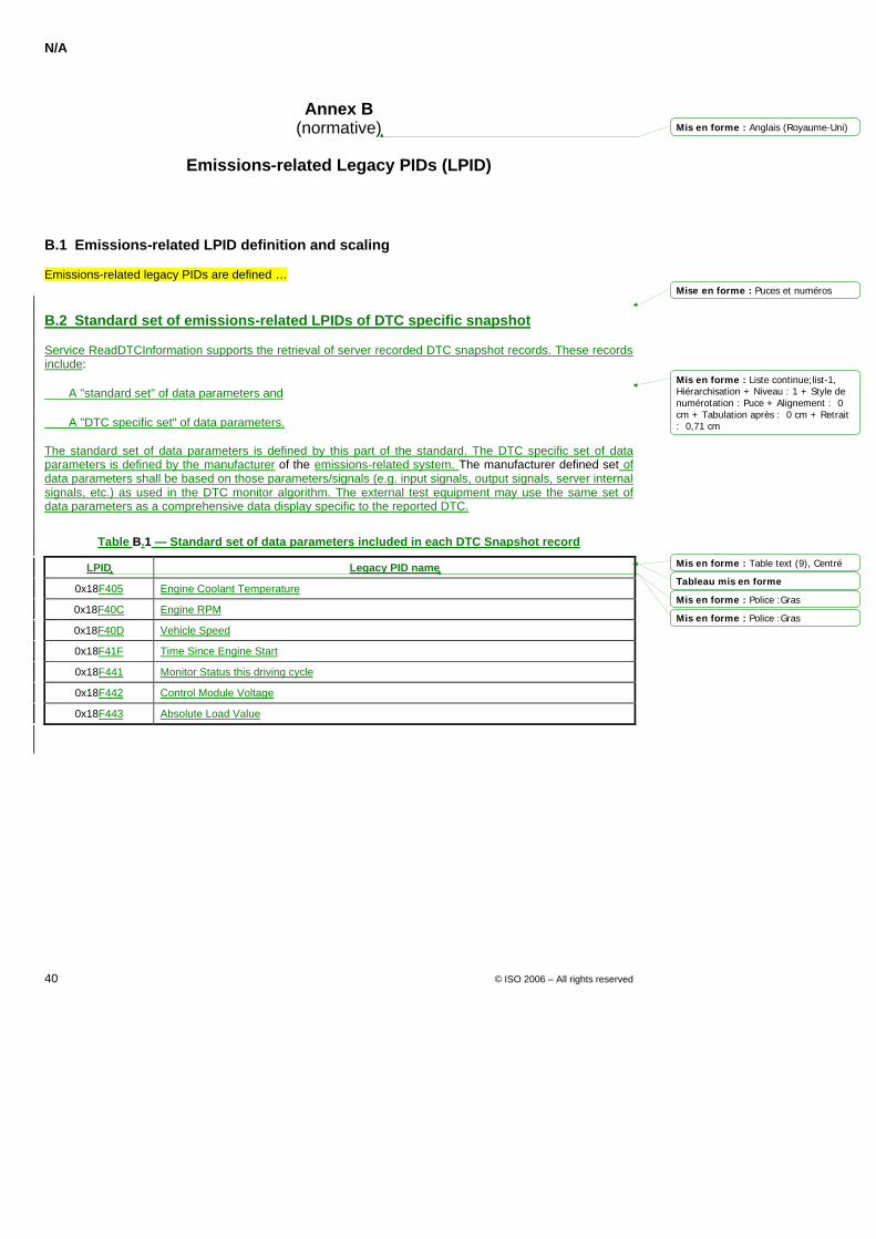
N/A
40 © ISO 2006 – All rights reserved
Annex B (normative)
Emissions-related Legacy PIDs (LPID)
B.1 Emissions-related LPID definition and scaling
Emissions-related legacy PIDs are defined …
B.2 Standard set of emissions-related LPIDs of DTC specific snapshot
Service ReadDTCInformation supports the retrieval of server recorded DTC snapshot records. These records include:
A "standard set" of data parameters and
A "DTC specific set" of data parameters.
The standard set of data parameters is defined by this part of the standard. The DTC specific set of data parameters is defined by the manufacturer of the emissions-related system. The manufacturer defined set of data parameters shall be based on those parameters/signals (e.g. input signals, output signals, server internal signals, etc.) as used in the DTC monitor algorithm. The external test equipment may use the same set of data parameters as a comprehensive data display specific to the reported DTC.
Table B.1 — Standard set of data parameters included in each DTC Snapshot record
LPID Legacy PID name
0x18F405 Engine Coolant Temperature
0x18F40C Engine RPM
0x18F40D Vehicle Speed
0x18F41F Time Since Engine Start
0x18F441 Monitor Status this driving cycle
0x18F442 Control Module Voltage
0x18F443 Absolute Load Value
Mis en forme : Anglais (Royaume-Uni)
Mise en forme : Puces et numéros
Mis en forme : Liste continue;list-1,Hiérarchisation + Niveau : 1 + Style denumérotation : Puce + Alignement : 0cm + Tabulation après : 0 cm + Retrait: 0,71 cm
Mis en forme : Table text (9), Centré
Tableau mis en forme
Mis en forme : Police :Gras
Mis en forme : Police :Gras
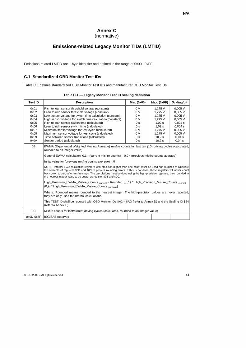
N/A
© ISO 2006 – All rights reserved 41
Annex C (normative)
Emissions-related Legacy Monitor TIDs (LMTID)
Emissions-related LMTID are 1-byte identifier and defined in the range of 0x00 - 0xFF.
C.1 Standardized OBD Monitor Test IDs
Table C.1 defines standardized OBD Monitor Test IDs and manufacturer OBD Monitor Test IDs.
Table C.1 — Legacy Monitor Test ID scaling definition
Test ID Description Min. (0x00) Max. (0xFF) Scaling/bit
0x01 0x02 0x03 0x04 0x05 0x06 0x07 0x08 0x09 0x0A
Rich to lean sensor threshold voltage (constant) Lean to rich sensor threshold voltage (constant) Low sensor voltage for switch time calculation (constant) High sensor voltage for switch time calculation (constant) Rich to lean sensor switch time (calculated) Lean to rich sensor switch time (calculated) Minimum sensor voltage for test cycle (calculated) Maximum sensor voltage for test cycle (calculated) Time between sensor transitions (calculated) Sensor period (calculated)
0 V 0 V 0 V 0 V 0 s 0 s 0 V 0 V 0 s 0 s
1,275 V 1,275 V 1,275 V 1,275 V 1,02 s 1,02 s
1,275 V 1,275 V 10,2 s 10,2 s
0,005 V 0,005 V 0,005 V 0,005 V 0,004 s 0,004 s 0,005 V 0,005 V 0,04 s 0,04 s
0B EWMA (Exponential Weighted Moving Average) misfire counts for last ten (10) driving cycles (calculated, rounded to an integer value)
General EWMA calculation: 0,1 * (current misfire counts) + 0,9 * (previous misfire counts average)
Initial value for (previous misfire counts average) = 0
NOTE Internal ECU calculation registers with precision higher than one count must be used and retained to calculate the contents of registers $0B and $0C to prevent rounding errors. If this is not done, these registers will never count back down to zero after misfire stops. The calculations must be done using the high-precision registers, then rounded to the nearest integer value to be output as register $0B and $0C.
High_Precision_EWMA_Misfire_Counts current = Rounded [(0,1) * High_Precision_Misfire_Counts current + (0,9) * High_Precision_EWMA_Misfire_Counts previous]
Where: Rounded means rounded to the nearest integer. The high-precision values are never reported, they are only used for internal calculations.
This TEST ID shall be reported with OBD Monitor IDs $A2 – $AD (refer to Annex D) and the Scaling ID $24 (refer to Annex E).
0C Misfire counts for last/current driving cycles (calculated, rounded to an integer value)
0x0D-0x7F ISO/SAE reserved
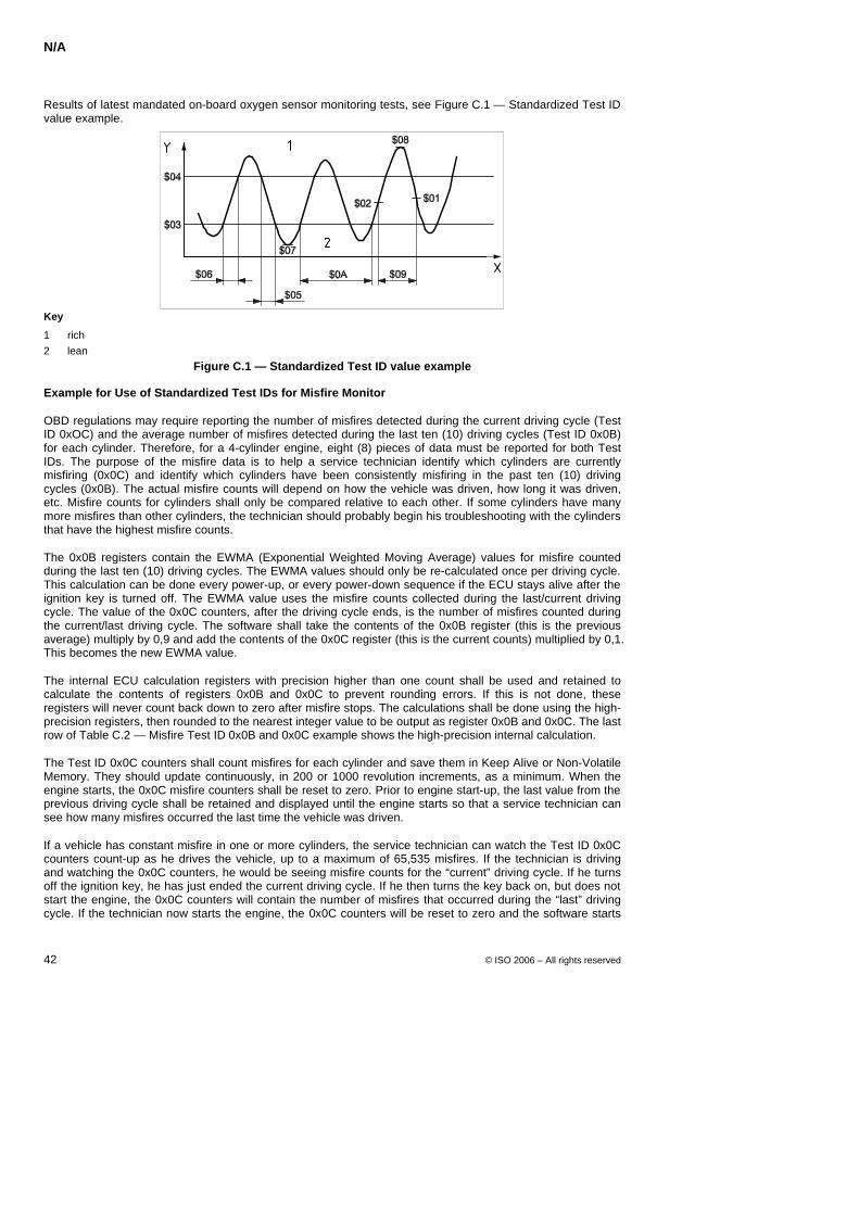
N/A
42 © ISO 2006 – All rights reserved
Results of latest mandated on-board oxygen sensor monitoring tests, see Figure C.1 — Standardized Test ID value example.
Key
1 rich 2 lean
Figure C.1 — Standardized Test ID value example
Example for Use of Standardized Test IDs for Misfire Monitor
OBD regulations may require reporting the number of misfires detected during the current driving cycle (Test ID 0xOC) and the average number of misfires detected during the last ten (10) driving cycles (Test ID 0x0B) for each cylinder. Therefore, for a 4-cylinder engine, eight (8) pieces of data must be reported for both Test IDs. The purpose of the misfire data is to help a service technician identify which cylinders are currently misfiring (0x0C) and identify which cylinders have been consistently misfiring in the past ten (10) driving cycles (0x0B). The actual misfire counts will depend on how the vehicle was driven, how long it was driven, etc. Misfire counts for cylinders shall only be compared relative to each other. If some cylinders have many more misfires than other cylinders, the technician should probably begin his troubleshooting with the cylinders that have the highest misfire counts.
The 0x0B registers contain the EWMA (Exponential Weighted Moving Average) values for misfire counted during the last ten (10) driving cycles. The EWMA values should only be re-calculated once per driving cycle. This calculation can be done every power-up, or every power-down sequence if the ECU stays alive after the ignition key is turned off. The EWMA value uses the misfire counts collected during the last/current driving cycle. The value of the 0x0C counters, after the driving cycle ends, is the number of misfires counted during the current/last driving cycle. The software shall take the contents of the 0x0B register (this is the previous average) multiply by 0,9 and add the contents of the 0x0C register (this is the current counts) multiplied by 0,1. This becomes the new EWMA value.
The internal ECU calculation registers with precision higher than one count shall be used and retained to calculate the contents of registers 0x0B and 0x0C to prevent rounding errors. If this is not done, these registers will never count back down to zero after misfire stops. The calculations shall be done using the high-precision registers, then rounded to the nearest integer value to be output as register 0x0B and 0x0C. The last row of Table C.2 — Misfire Test ID 0x0B and 0x0C example shows the high-precision internal calculation.
The Test ID 0x0C counters shall count misfires for each cylinder and save them in Keep Alive or Non-Volatile Memory. They should update continuously, in 200 or 1000 revolution increments, as a minimum. When the engine starts, the 0x0C misfire counters shall be reset to zero. Prior to engine start-up, the last value from the previous driving cycle shall be retained and displayed until the engine starts so that a service technician can see how many misfires occurred the last time the vehicle was driven.
If a vehicle has constant misfire in one or more cylinders, the service technician can watch the Test ID 0x0C counters count-up as he drives the vehicle, up to a maximum of 65,535 misfires. If the technician is driving and watching the 0x0C counters, he would be seeing misfire counts for the “current” driving cycle. If he turns off the ignition key, he has just ended the current driving cycle. If he then turns the key back on, but does not start the engine, the 0x0C counters will contain the number of misfires that occurred during the “last” driving cycle. If the technician now starts the engine, the 0x0C counters will be reset to zero and the software starts
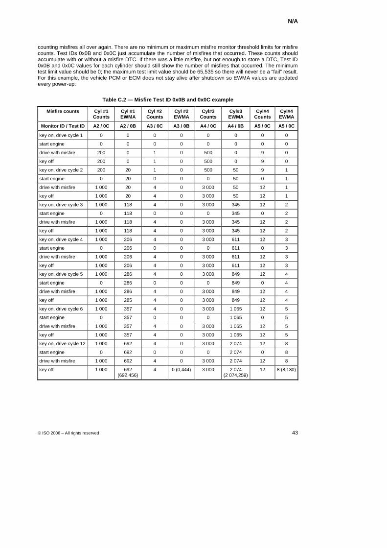
N/A
© ISO 2006 – All rights reserved 43
counting misfires all over again. There are no minimum or maximum misfire monitor threshold limits for misfire counts. Test IDs 0x0B and 0x0C just accumulate the number of misfires that occurred. These counts should accumulate with or without a misfire DTC. If there was a little misfire, but not enough to store a DTC, Test ID 0x0B and 0x0C values for each cylinder should still show the number of misfires that occurred. The minimum test limit value should be 0; the maximum test limit value should be 65,535 so there will never be a “fail” result. For this example, the vehicle PCM or ECM does not stay alive after shutdown so EWMA values are updated every power-up:
Table C.2 — Misfire Test ID 0x0B and 0x0C example
Misfire counts Cyl #1 Counts
Cyl #1 EWMA
Cyl #2 Counts
Cyl #2 EWMA
Cyl#3 Counts
Cyl#3 EWMA
Cyl#4 Counts
Cyl#4 EWMA
Monitor ID / Test ID A2 / 0C A2 / 0B A3 / 0C A3 / 0B A4 / 0C A4 / 0B A5 / 0C A5 / 0C
key on, drive cycle 1 0 0 0 0 0 0 0 0
start engine 0 0 0 0 0 0 0 0
drive with misfire 200 0 1 0 500 0 9 0
key off 200 0 1 0 500 0 9 0
key on, drive cycle 2 200 20 1 0 500 50 9 1
start engine 0 20 0 0 0 50 0 1
drive with misfire 1 000 20 4 0 3 000 50 12 1
key off 1 000 20 4 0 3 000 50 12 1
key on, drive cycle 3 1 000 118 4 0 3 000 345 12 2
start engine 0 118 0 0 0 345 0 2
drive with misfire 1 000 118 4 0 3 000 345 12 2
key off 1 000 118 4 0 3 000 345 12 2
key on, drive cycle 4 1 000 206 4 0 3 000 611 12 3
start engine 0 206 0 0 0 611 0 3
drive with misfire 1 000 206 4 0 3 000 611 12 3
key off 1 000 206 4 0 3 000 611 12 3
key on, drive cycle 5 1 000 286 4 0 3 000 849 12 4
start engine 0 286 0 0 0 849 0 4
drive with misfire 1 000 286 4 0 3 000 849 12 4
key off 1 000 285 4 0 3 000 849 12 4
key on, drive cycle 6 1 000 357 4 0 3 000 1 065 12 5
start engine 0 357 0 0 0 1 065 0 5
drive with misfire 1 000 357 4 0 3 000 1 065 12 5
key off 1 000 357 4 0 3 000 1 065 12 5
key on, drive cycle 12 1 000 692 4 0 3 000 2 074 12 8
start engine 0 692 0 0 0 2 074 0 8
drive with misfire 1 000 692 4 0 3 000 2 074 12 8
key off 1 000 692 (692,456)
4 0 (0,444) 3 000 2 074 (2 074,259)
12 8 (8,130)
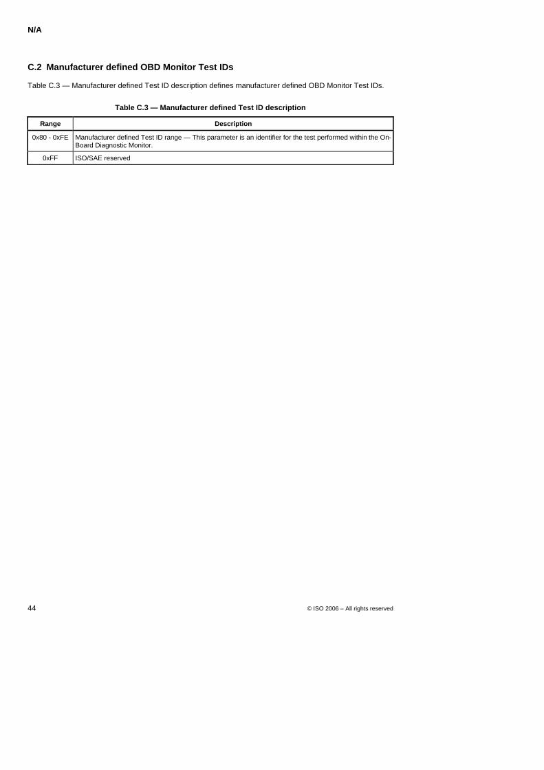
N/A
44 © ISO 2006 – All rights reserved
C.2 Manufacturer defined OBD Monitor Test IDs
Table C.3 — Manufacturer defined Test ID description defines manufacturer defined OBD Monitor Test IDs.
Table C.3 — Manufacturer defined Test ID description
Range Description
0x80 - 0xFE Manufacturer defined Test ID range — This parameter is an identifier for the test performed within the On-Board Diagnostic Monitor.
0xFF ISO/SAE reserved
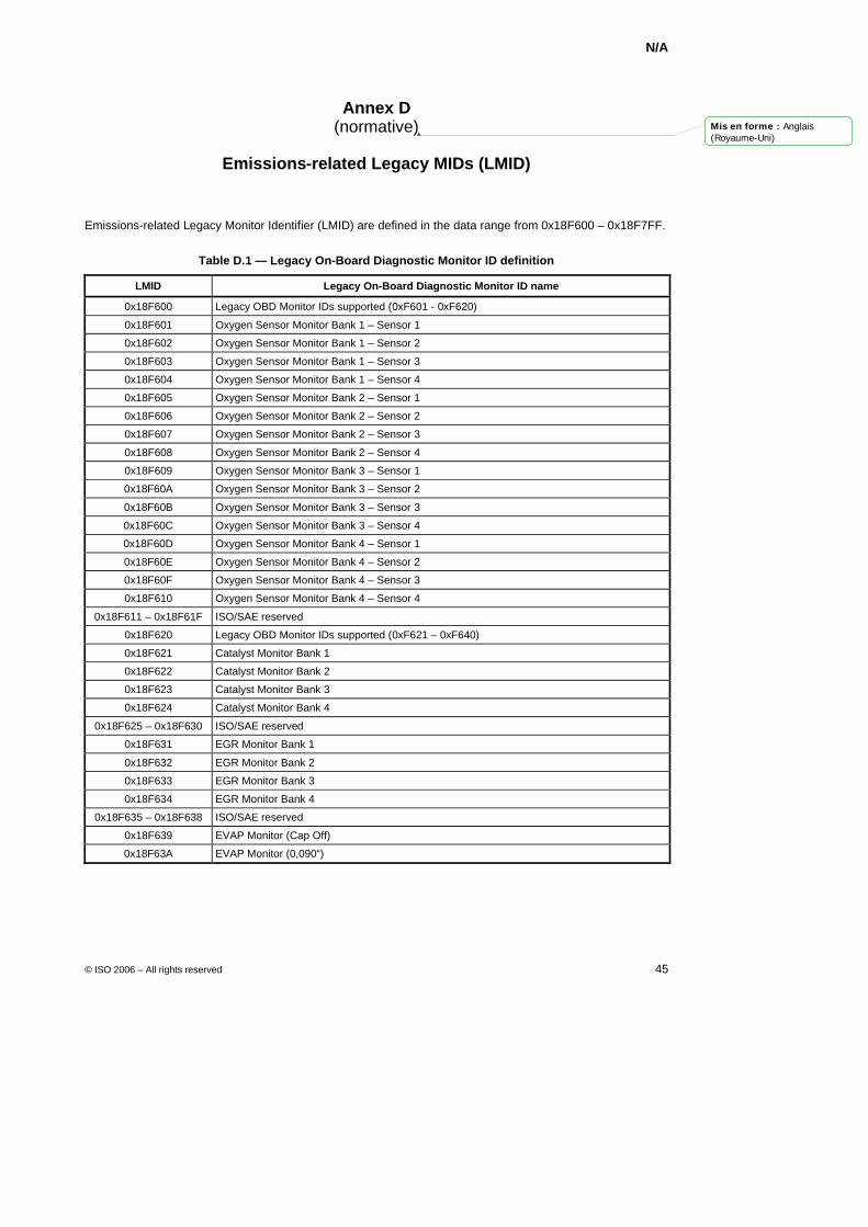
N/A
© ISO 2006 – All rights reserved 45
Annex D (normative)
Emissions-related Legacy MIDs (LMID)
Emissions-related Legacy Monitor Identifier (LMID) are defined in the data range from 0x18F600 – 0x18F7FF.
Table D.1 — Legacy On-Board Diagnostic Monitor ID definition
LMID Legacy On-Board Diagnostic Monitor ID name
0x18F600 Legacy OBD Monitor IDs supported (0xF601 - 0xF620)
0x18F601 Oxygen Sensor Monitor Bank 1 – Sensor 1
0x18F602 Oxygen Sensor Monitor Bank 1 – Sensor 2
0x18F603 Oxygen Sensor Monitor Bank 1 – Sensor 3
0x18F604 Oxygen Sensor Monitor Bank 1 – Sensor 4
0x18F605 Oxygen Sensor Monitor Bank 2 – Sensor 1
0x18F606 Oxygen Sensor Monitor Bank 2 – Sensor 2
0x18F607 Oxygen Sensor Monitor Bank 2 – Sensor 3
0x18F608 Oxygen Sensor Monitor Bank 2 – Sensor 4
0x18F609 Oxygen Sensor Monitor Bank 3 – Sensor 1
0x18F60A Oxygen Sensor Monitor Bank 3 – Sensor 2
0x18F60B Oxygen Sensor Monitor Bank 3 – Sensor 3
0x18F60C Oxygen Sensor Monitor Bank 3 – Sensor 4
0x18F60D Oxygen Sensor Monitor Bank 4 – Sensor 1
0x18F60E Oxygen Sensor Monitor Bank 4 – Sensor 2
0x18F60F Oxygen Sensor Monitor Bank 4 – Sensor 3
0x18F610 Oxygen Sensor Monitor Bank 4 – Sensor 4
0x18F611 – 0x18F61F ISO/SAE reserved
0x18F620 Legacy OBD Monitor IDs supported (0xF621 – 0xF640)
0x18F621 Catalyst Monitor Bank 1
0x18F622 Catalyst Monitor Bank 2
0x18F623 Catalyst Monitor Bank 3
0x18F624 Catalyst Monitor Bank 4
0x18F625 – 0x18F630 ISO/SAE reserved
0x18F631 EGR Monitor Bank 1
0x18F632 EGR Monitor Bank 2
0x18F633 EGR Monitor Bank 3
0x18F634 EGR Monitor Bank 4
0x18F635 – 0x18F638 ISO/SAE reserved
0x18F639 EVAP Monitor (Cap Off)
0x18F63A EVAP Monitor (0,090“)
Mis en forme : Anglais(Royaume-Uni)
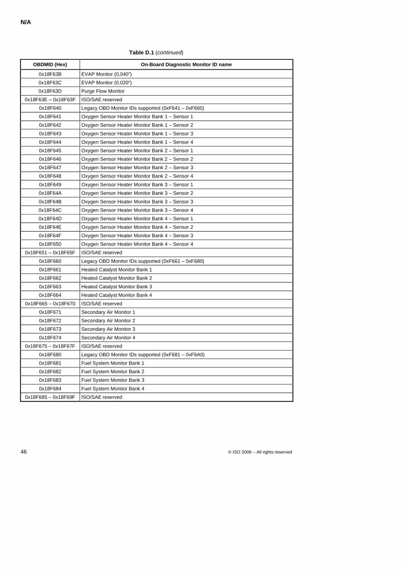
N/A
46 © ISO 2006 – All rights reserved
Table D.1 (continued)
OBDMID (Hex) On-Board Diagnostic Monitor ID name
0x18F63B EVAP Monitor (0,040”)
0x18F63C EVAP Monitor (0,020“)
0x18F63D Purge Flow Monitor
0x18F63E – 0x18F63F ISO/SAE reserved
0x18F640 Legacy OBD Monitor IDs supported (0xF641 – 0xF660)
0x18F641 Oxygen Sensor Heater Monitor Bank 1 – Sensor 1
0x18F642 Oxygen Sensor Heater Monitor Bank 1 – Sensor 2
0x18F643 Oxygen Sensor Heater Monitor Bank 1 – Sensor 3
0x18F644 Oxygen Sensor Heater Monitor Bank 1 – Sensor 4
0x18F645 Oxygen Sensor Heater Monitor Bank 2 – Sensor 1
0x18F646 Oxygen Sensor Heater Monitor Bank 2 – Sensor 2
0x18F647 Oxygen Sensor Heater Monitor Bank 2 – Sensor 3
0x18F648 Oxygen Sensor Heater Monitor Bank 2 – Sensor 4
0x18F649 Oxygen Sensor Heater Monitor Bank 3 – Sensor 1
0x18F64A Oxygen Sensor Heater Monitor Bank 3 – Sensor 2
0x18F64B Oxygen Sensor Heater Monitor Bank 3 – Sensor 3
0x18F64C Oxygen Sensor Heater Monitor Bank 3 – Sensor 4
0x18F64D Oxygen Sensor Heater Monitor Bank 4 – Sensor 1
0x18F64E Oxygen Sensor Heater Monitor Bank 4 – Sensor 2
0x18F64F Oxygen Sensor Heater Monitor Bank 4 – Sensor 3
0x18F650 Oxygen Sensor Heater Monitor Bank 4 – Sensor 4
0x18F651 – 0x18F65F ISO/SAE reserved
0x18F660 Legacy OBD Monitor IDs supported (0xF661 – 0xF680)
0x18F661 Heated Catalyst Monitor Bank 1
0x18F662 Heated Catalyst Monitor Bank 2
0x18F663 Heated Catalyst Monitor Bank 3
0x18F664 Heated Catalyst Monitor Bank 4
0x18F665 – 0x18F670 ISO/SAE reserved
0x18F671 Secondary Air Monitor 1
0x18F672 Secondary Air Monitor 2
0x18F673 Secondary Air Monitor 3
0x18F674 Secondary Air Monitor 4
0x18F675 – 0x18F67F ISO/SAE reserved
0x18F680 Legacy OBD Monitor IDs supported (0xF681 – 0xF6A0)
0x18F681 Fuel System Monitor Bank 1
0x18F682 Fuel System Monitor Bank 2
0x18F683 Fuel System Monitor Bank 3
0x18F684 Fuel System Monitor Bank 4
0x18F685 – 0x18F69F ISO/SAE reserved
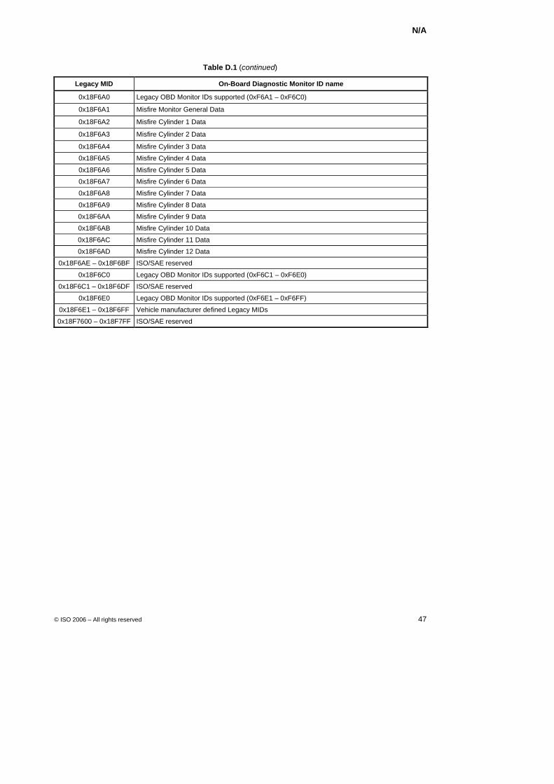
N/A
© ISO 2006 – All rights reserved 47
Table D.1 (continued)
Legacy MID On-Board Diagnostic Monitor ID name
0x18F6A0 Legacy OBD Monitor IDs supported (0xF6A1 – 0xF6C0)
0x18F6A1 Misfire Monitor General Data
0x18F6A2 Misfire Cylinder 1 Data
0x18F6A3 Misfire Cylinder 2 Data
0x18F6A4 Misfire Cylinder 3 Data
0x18F6A5 Misfire Cylinder 4 Data
0x18F6A6 Misfire Cylinder 5 Data
0x18F6A7 Misfire Cylinder 6 Data
0x18F6A8 Misfire Cylinder 7 Data
0x18F6A9 Misfire Cylinder 8 Data
0x18F6AA Misfire Cylinder 9 Data
0x18F6AB Misfire Cylinder 10 Data
0x18F6AC Misfire Cylinder 11 Data
0x18F6AD Misfire Cylinder 12 Data
0x18F6AE – 0x18F6BF ISO/SAE reserved
0x18F6C0 Legacy OBD Monitor IDs supported (0xF6C1 – 0xF6E0)
0x18F6C1 – 0x18F6DF ISO/SAE reserved
0x18F6E0 Legacy OBD Monitor IDs supported (0xF6E1 – 0xF6FF)
0x18F6E1 – 0x18F6FF Vehicle manufacturer defined Legacy MIDs
0x18F7600 – 0x18F7FF ISO/SAE reserved
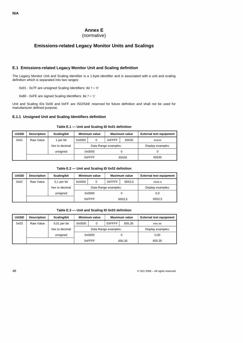
N/A
48 © ISO 2006 – All rights reserved
Annex E (normative)
Emissions-related Legacy Monitor Units and Scalings
E.1 Emissions-related Legacy Monitor Unit and Scaling definition
The Legacy Monitor Unit and Scaling Identifier is a 1-byte identifier and is associated with a unit and scaling definition which is separated into two ranges:
0x01 - 0x7F are unsigned Scaling Identifiers: Bit 7 = ‘0’
0x80 - 0xFE are signed Scaling Identifiers: Bit 7 = ‘1’
Unit and Scaling IDs 0x00 and 0xFF are ISO/SAE reserved for future definition and shall not be used for manufacturer defined purpose.
E.1.1 Unsigned Unit and Scaling Identifiers definition
Table E.1 — Unit and Scaling ID 0x01 definition
UASID Description Scaling/bit Minimum value Maximum value External test equipment
0x01 Raw Value 1 per bit 0x0000 0 0xFFFF 65535 xxxxx
hex to decimal Data Range examples: Display examples:
unsigned 0x0000 0 0
0xFFFF + 65535 65535
Table E.2 — Unit and Scaling ID 0x02 definition
UASID Description Scaling/bit Minimum value Maximum value External test equipment
0x02 Raw Value 0,1 per bit 0x0000 0 0XFFFF 6553,5 xxxx.x
hex to decimal Data Range examples: Display examples:
unsigned 0x0000 0 0,0
0xFFFF + 6553,5 6553,5
Table E.3 — Unit and Scaling ID 0x03 definition
UASID Description Scaling/bit Minimum value Maximum value External test equipment
0x03 Raw Value 0,01 per bit 0x0000 0 0XFFFF 655,35 xxx.xx
hex to decimal Data Range examples: Display examples:
unsigned 0x0000 0 0,00
0xFFFF + 655,35 655,35
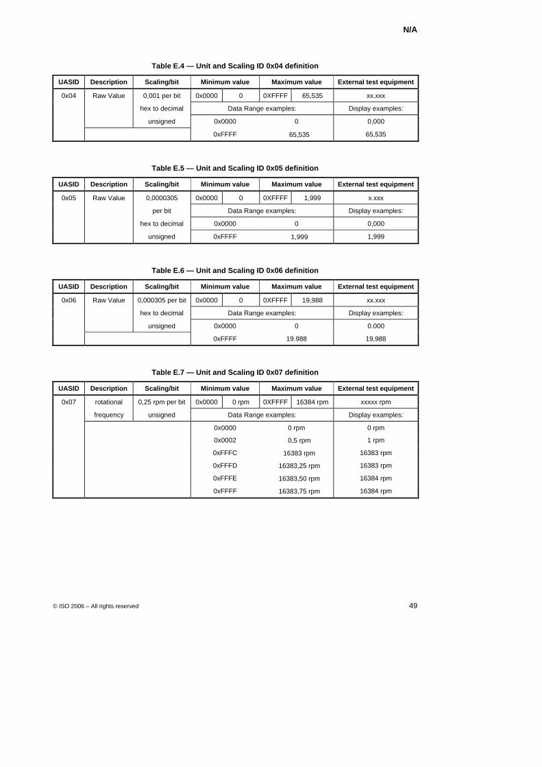
N/A
© ISO 2006 – All rights reserved 49
Table E.4 — Unit and Scaling ID 0x04 definition
UASID Description Scaling/bit Minimum value Maximum value External test equipment
0x04 Raw Value 0,001 per bit 0x0000 0 0XFFFF 65,535 xx.xxx
hex to decimal Data Range examples: Display examples:
unsigned 0x0000 0 0,000
0xFFFF + 65,535 65,535
Table E.5 — Unit and Scaling ID 0x05 definition
UASID Description Scaling/bit Minimum value Maximum value External test equipment
0x05 Raw Value 0,0000305 0x0000 0 0XFFFF 1,999 x.xxx
per bit Data Range examples: Display examples:
hex to decimal 0x0000 0 0,000
unsigned 0xFFFF + 1,999 1,999
Table E.6 — Unit and Scaling ID 0x06 definition
UASID Description Scaling/bit Minimum value Maximum value External test equipment
0x06 Raw Value 0,000305 per bit 0x0000 0 0XFFFF 19,988 xx.xxx
hex to decimal Data Range examples: Display examples:
unsigned 0x0000 0 0.000
0xFFFF 19.988 19,988
Table E.7 — Unit and Scaling ID 0x07 definition
UASID Description Scaling/bit Minimum value Maximum value External test equipment
0x07 rotational 0,25 rpm per bit 0x0000 0 rpm 0XFFFF 16384 rpm xxxxx rpm
frequency unsigned Data Range examples: Display examples:
0x0000 0 rpm 0 rpm
0x0002 + 0,5 rpm 1 rpm
0xFFFC + 16383 rpm 16383 rpm
0xFFFD + 16383,25 rpm 16383 rpm
0xFFFE + 16383,50 rpm 16384 rpm
0xFFFF + 16383,75 rpm 16384 rpm
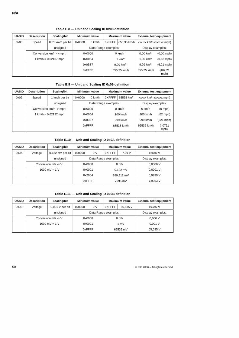
N/A
50 © ISO 2006 – All rights reserved
Table E.8 — Unit and Scaling ID 0x08 definition
UASID Description Scaling/bit Minimum value Maximum value External test equipment
0x08 Speed 0,01 km/h per bit 0x0000 0 km/h 0XFFFF 655,35 km/h xxx.xx km/h (xxx.xx mph)
unsigned Data Range examples: Display examples:
Conversion km/h -> mph: 0x0000 0 km/h 0,00 km/h (0,00 mph)
1 km/h = 0.62137 mph 0x0064 + 1 km/h 1,00 km/h (0,62 mph)
0x03E7 + 9,99 km/h 9,99 km/h (6,21 mph)
0xFFFF + 655,35 km/h 655,35 km/h (407,21 mph)
Table E.9 — Unit and Scaling ID 0x09 definition
UASID Description Scaling/bit Minimum value Maximum value External test equipment
0x09 Speed 1 km/h per bit 0x0000 0 km/h 0XFFFF 65535 km/h xxxxx km/h (xxxxx mph)
unsigned Data Range examples: Display examples:
Conversion km/h -> mph: 0x0000 0 km/h 0 km/h (0 mph)
1 km/h = 0,62137 mph 0x0064 + 100 km/h 100 km/h (62 mph)
0x03E7 + 999 km/h 999 km/h (621 mph)
0xFFFF + 65535 km/h 65535 km/h (40721 mph)
Table E.10 — Unit and Scaling ID 0x0A definition
UASID Description Scaling/bit Minimum value Maximum value External test equipment
0x0A Voltage 0,122 mV per bit 0x0000 0 V 0XFFFF 7,99 V x.xxxx V
unsigned Data Range examples: Display examples:
Conversion mV -> V: 0x0000 0 mV 0,0000 V
1000 mV = 1 V 0x0001 + 0,122 mV 0,0001 V
0x2004 + 999,912 mV 0,9999 V
0xFFFF + 7995 mV 7,9953 V
Table E.11 — Unit and Scaling ID 0x0B definition
UASID Description Scaling/bit Minimum value Maximum value External test equipment
0x0B Voltage 0,001 V per bit 0x0000 0 V 0XFFFF 65,535 V xx.xxx V
unsigned Data Range examples: Display examples:
Conversion mV -> V: 0x0000 0 mV 0,000 V
1000 mV = 1 V 0x0001 + 1 mV 0,001 V
0xFFFF + 65535 mV 65,535 V
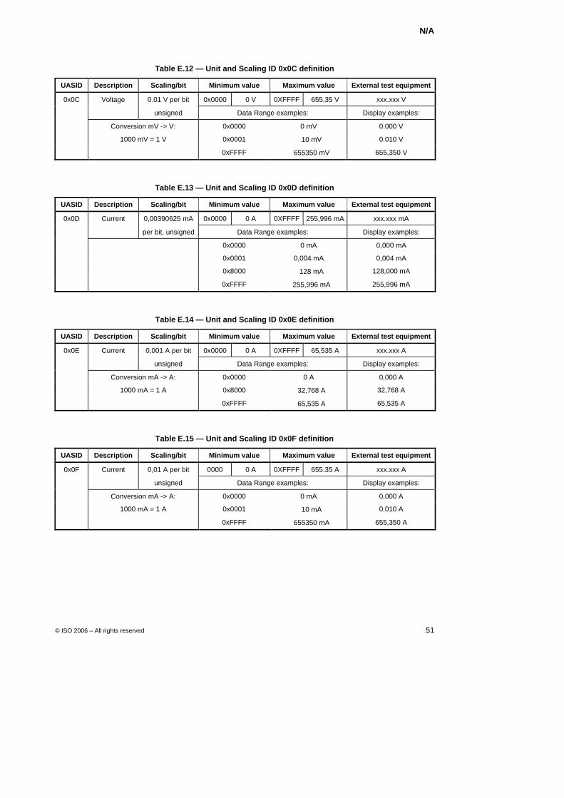
N/A
© ISO 2006 – All rights reserved 51
Table E.12 — Unit and Scaling ID 0x0C definition
UASID Description Scaling/bit Minimum value Maximum value External test equipment
0x0C Voltage 0.01 V per bit 0x0000 0 V 0XFFFF 655,35 V xxx.xxx V
unsigned Data Range examples: Display examples:
Conversion mV -> V: 0x0000 0 mV 0.000 V
1000 mV = 1 V 0x0001 + 10 mV 0.010 V
0xFFFF + 655350 mV 655,350 V
Table E.13 — Unit and Scaling ID 0x0D definition
UASID Description Scaling/bit Minimum value Maximum value External test equipment
0x0D Current 0,00390625 mA 0x0000 0 A 0XFFFF 255,996 mA xxx.xxx mA
per bit, unsigned Data Range examples: Display examples:
0x0000 0 mA 0,000 mA
0x0001 0,004 mA 0,004 mA
0x8000 + 128 mA 128,000 mA
0xFFFF + 255,996 mA 255,996 mA
Table E.14 — Unit and Scaling ID 0x0E definition
UASID Description Scaling/bit Minimum value Maximum value External test equipment
0x0E Current 0,001 A per bit 0x0000 0 A 0XFFFF 65,535 A xxx.xxx A
unsigned Data Range examples: Display examples:
Conversion mA -> A: 0x0000 0 A 0,000 A
1000 mA = 1 A 0x8000 + 32,768 A 32,768 A
0xFFFF + 65,535 A 65,535 A
Table E.15 — Unit and Scaling ID 0x0F definition
UASID Description Scaling/bit Minimum value Maximum value External test equipment
0x0F Current 0,01 A per bit 0000 0 A 0XFFFF 655.35 A xxx.xxx A
unsigned Data Range examples: Display examples:
Conversion mA -> A: 0x0000 0 mA 0,000 A
1000 mA = 1 A 0x0001 + 10 mA 0,010 A
0xFFFF + 655350 mA 655,350 A
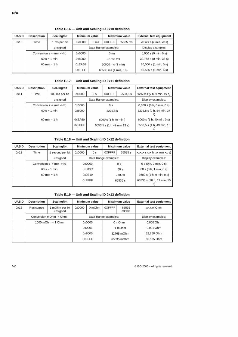
N/A
52 © ISO 2006 – All rights reserved
Table E.16 — Unit and Scaling ID 0x10 definition
UASID Description Scaling/bit Minimum value Maximum value External test equipment
0x10 Time 1 ms per bit 0x0000 0 ms 0XFFFF 65535 ms xx.xxx s (x min, xx s)
unsigned Data Range examples: Display examples:
Conversion s -> min -> h: 0x0000 0 ms 0,000 s (0 min, 0 s)
60 s = 1 min 0x8000 + 32768 ms 32,768 s (0 min, 33 s)
60 min = 1 h 0xEA60 + 60000 ms (1 min) 60,000 s (1 min, 0 s)
0xFFFF + 65535 ms (1 min, 6 s) 65,535 s (1 min, 6 s)
Table E.17 — Unit and Scaling ID 0x11 definition
UASID Description Scaling/bit Minimum value Maximum value External test equipment
0x11 Time 100 ms per bit 0x0000 0 s 0XFFFF 6553,5 s xxxx.x s (x h, x min, xx s)
unsigned Data Range examples: Display examples:
Conversion s -> min -> h: 0x0000 0 s 0,000 s (0 h, 0 min, 0 s)
60 s = 1 min 0x8000 + 3276.8 s 3276,8 s (0 h, 54 min, 37 s)
60 min = 1 h 0xEA60 + 6000 s (1 h 40 min ) 6000 s (1 h, 40 min, 0 s)
0xFFFF + 6553.5 s (1h, 49 min 13 s) 6553,5 s (1 h, 49 min, 13 s)
Table E.18 — Unit and Scaling ID 0x12 definition
UASID Description Scaling/bit Minimum value Maximum value External test equipment
0x12 Time 1 second per bit 0x0000 0 s 0XFFFF 65535 s xxxxx s (xx h, xx min xx s)
unsigned Data Range examples: Display examples:
Conversion s -> min -> h: 0x0000 0 s 0 s (0 h, 0 min, 0 s)
60 s = 1 min 0x003C + 60 s 60 s (0 h, 1 min, 0 s)
60 min = 1 h 0x0E10 + 3600 s 3600 s (1 h, 0 min, 0 s)
0xFFFF + 65535 s 65535 s (18 h, 12 min, 15 s)
Table E.19 — Unit and Scaling ID 0x13 definition
UASID Description Scaling/bit Minimum value Maximum value External test equipment
0x13 Resistance 1 mOhm per bit unsigned
0x0000 0 mOhm 0XFFFF 65535 mOhm
xx.xxx Ohm
Conversion mOhm -> Ohm: Data Range examples: Display examples:
1000 mOhm = 1 Ohm 0x0000 0 mOhm 0,000 Ohm
0x0001 + 1 mOhm 0,001 Ohm
0x8000 + 32768 mOhm 32,768 Ohm
0xFFFF + 65535 mOhm 65,535 Ohm
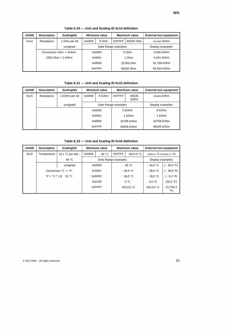
N/A
© ISO 2006 – All rights reserved 53
Table E.20 — Unit and Scaling ID 0x14 definition
UASID Description Scaling/bit Minimum value Maximum value External test equipment
0x14 Resistance 1 Ohm per bit 0x0000 0 Ohm 0XFFFF 65535 Ohm xx.xxx kOhm
unsigned Data Range examples: Display examples:
Conversion Ohm -> kOhm: 0x0000 0 Ohm 0,000 kOhm
1000 Ohm = 1 kOhm 0x0001 + 1 Ohm 0,001 kOhm
0x8000 + 32768 Ohm 32,768 kOhm
0xFFFF + 65535 Ohm 65,535 kOhm
Table E.21 — Unit and Scaling ID 0x15 definition
UASID Description Scaling/bit Minimum value Maximum value External test equipment
0x15 Resistance 1 kOhm per bit 0x0000 0 kOhm 0XFFFF 65535 kOhm
xxxxx kOhm
unsigned Data Range examples: Display examples:
0x0000 0 kOhm 0 kOhm
0x0001 + 1 kOhm 1 kOhm
0x8000 + 32768 kOhm 32768 kOhm
0xFFFF + 65535 kOhm 65535 kOhm
Table E.22 — Unit and Scaling ID 0x16 definition
UASID Description Scaling/bit Minimum value Maximum value External test equipment
0x16 Temperature (0.1 °C per bit) - 0x0000 − 40 °C 0XFFFF + 6513.5 °C xxxx.x °C (xxxxx.x °F)
40 °C Data Range examples: Display examples:
unsigned 0x0000 − 40 °C − 40,0 °C (− 40,0 °F)
Conversion °C -> °F: 0x0001 − 39,9 °C − 39,9 °C (− 39,8 °F)
°F = °C * 1.8 + 32 °C 0x00DC − 18,0 °C − 18,0 °C (− 0,4 °F)
0x0190 0 °C 0,0 °C (32,0 °F)
0xFFFF + 6513,5 °C 6513,5 °C (11756,3 °F)
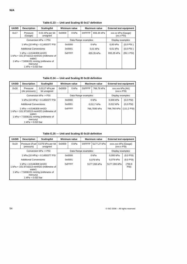
N/A
54 © ISO 2006 – All rights reserved
Table E.23 — Unit and Scaling ID 0x17 definition
UASID Description Scaling/bit Minimum value Maximum value External test equipment
0x17 Pressure (Gauge)
0.01 kPa per bit unsigned
0x0000 0 kPa 0XFFFF 655.35 kPa xxx.xx kPa (Gauge) (xx.x PSI)
Conversion kPa -> PSI: Data Range examples: Display examples:
1 kPa (10 HPa) = 0,1450377 PSI 0x0000 0 kPa 0,00 kPa (0,0 PSI )
Additional Conversions: 0x0001 + 0,01 kPa 0,01 kPa (0,0 PSI )
1 kPa = 4,0146309 inH2O 1 kPa = 101,9716213 mmH2O (millimetre of
water) 1 kPa = 7,5006151 mmHg (millimetre of
mercury) 1 kPa = 0,010 bar
0xFFFF + 655,35 kPa 655,35 kPa (95,1 PSI)
Table E.24 — Unit and Scaling ID 0x18 definition
UASID Description Scaling/bit Minimum value Maximum value External test equipment
0x18 Pressure (Air pressure)
0,0117 kPa per bit unsigned
0x0000 0 kPa 0XFFFF 766,76 kPa xxx.xxx kPa (Air) (xxx.x PSI)
Conversion kPa -> PSI: Data Range examples: Display examples:
1 kPa (10 HPa) = 0.1450377 PSI 0x0000 0 kPa 0,000 kPa (0,0 PSI)
Additional Conversions: 0x0001 + 0,0117 kPa 0,012 kPa (0,0 PSI)
1 kPa = 4.0146309 inH2O 1 kPa = 101.9716213 mmH2O (millimetre of
water) 1 kPa = 7.5006151 mmHg (millimetre of
mercury) 1 kPa = 0.010 bar
0xFFFF + 766,7595 kPa 766,760 kPa (111,2 PSI)
Table E.25 — Unit and Scaling ID 0x19 definition
UASID Description Scaling/bit Minimum value Maximum value External test equipment
0x19 Pressure (Fuel pressure)
0,079 kPa per bit unsigned
0x0000 0 kPa 0XFFFF 5177,27 kPa xxxx.xxx kPa (Gauge) (xxx.x PSI)
Conversion kPa -> PSI: Data Range examples: Display examples:
1 kPa (10 HPa) = 0.1450377 PSI 0x0000 0 kPa 0,000 kPa (0,0 PSI)
Additional Conversions: 0x0001 + 0,079 kPa 0,079 kPa (0,0 PSI)
1 kPa = 4.0146309 inH2O 1 kPa = 101.9716213 mmH2O (millimetre of
water) 1 kPa = 7.5006151 mmHg (millimetre of
mercury) 1 kPa = 0.010 bar
0xFFFF + 5177,265 kPa 5177,265 kPa (750,9 PSI)
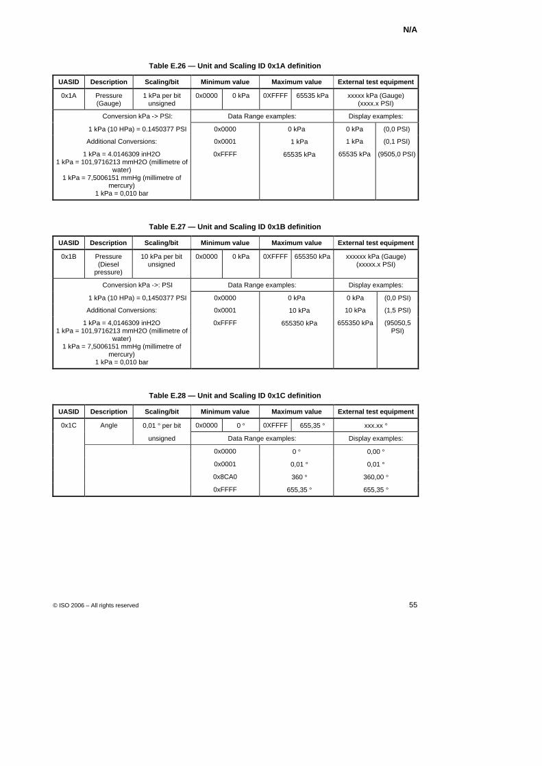
N/A
© ISO 2006 – All rights reserved 55
Table E.26 — Unit and Scaling ID 0x1A definition
UASID Description Scaling/bit Minimum value Maximum value External test equipment
0x1A Pressure (Gauge)
1 kPa per bit unsigned
0x0000 0 kPa 0XFFFF 65535 kPa xxxxx kPa (Gauge) (xxxx.x PSI)
Conversion kPa -> PSI: Data Range examples: Display examples:
1 kPa (10 HPa) = 0.1450377 PSI 0x0000 0 kPa 0 kPa (0,0 PSI)
Additional Conversions: 0x0001 + 1 kPa 1 kPa (0,1 PSI)
1 kPa = 4.0146309 inH2O 1 kPa = 101,9716213 mmH2O (millimetre of
water) 1 kPa = 7,5006151 mmHg (millimetre of
mercury) 1 kPa = 0,010 bar
0xFFFF + 65535 kPa 65535 kPa (9505,0 PSI)
Table E.27 — Unit and Scaling ID 0x1B definition
UASID Description Scaling/bit Minimum value Maximum value External test equipment
0x1B Pressure (Diesel
pressure)
10 kPa per bit unsigned
0x0000 0 kPa 0XFFFF 655350 kPa xxxxxx kPa (Gauge) (xxxxx.x PSI)
Conversion kPa ->: PSI Data Range examples: Display examples:
1 kPa (10 HPa) = 0,1450377 PSI 0x0000 0 kPa 0 kPa (0,0 PSI)
Additional Conversions: 0x0001 + 10 kPa 10 kPa (1,5 PSI)
1 kPa = 4,0146309 inH2O 1 kPa = 101,9716213 mmH2O (millimetre of
water) 1 kPa = 7,5006151 mmHg (millimetre of
mercury) 1 kPa = 0,010 bar
0xFFFF + 655350 kPa 655350 kPa (95050,5 PSI)
Table E.28 — Unit and Scaling ID 0x1C definition
UASID Description Scaling/bit Minimum value Maximum value External test equipment
0x1C Angle 0,01 ° per bit 0x0000 0 ° 0XFFFF 655,35 ° xxx.xx °
unsigned Data Range examples: Display examples:
0x0000 0 ° 0,00 °
0x0001 + 0,01 ° 0,01 °
0x8CA0 + 360 ° 360,00 °
0xFFFF + 655,35 ° 655,35 °
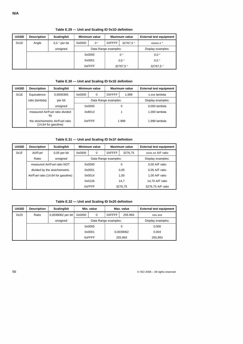
N/A
56 © ISO 2006 – All rights reserved
Table E.29 — Unit and Scaling ID 0x1D definition
UASID Description Scaling/bit Minimum value Maximum value External test equipment
0x1D Angle 0,5 ° per bit 0x0000 0 ° 0XFFFF 32767,5 ° xxxxx.x °
unsigned Data Range examples: Display examples:
0x0000 0 ° 0,0 °
0x0001 0,5 ° 0,5 °
0xFFFF 32767,5 ° 32767,5 °
Table E.30 — Unit and Scaling ID 0x1E definition
UASID Description Scaling/bit Minimum value Maximum value External test equipment
0x1E Equivalence 0,0000305 0x0000 0 0XFFFF 1,999 x.xxx lambda
ratio (lambda) per bit Data Range examples: Display examples:
unsigned 0x0000 0 0,000 lambda
measured Air/Fuel ratio divided by
0x8013 1 1,000 lambda
the stoichiometric Air/Fuel ratio (14,64 for gasoline)
0xFFFF 1.999 1,999 lambda
Table E.31 — Unit and Scaling ID 0x1F definition
UASID Description Scaling/bit Minimum value Maximum value External test equipment
0x1F Air/Fuel 0,05 per bit 0x0000 0 0XFFFF 3276,75 xxxx.xx A/F ratio
Ratio unsigned Data Range examples: Display examples:
measured Air/Fuel ratio NOT 0x0000 0 0,00 A/F ratio
divided by the stoichiometric 0x0001 0,05 0,05 A/F ratio
Air/Fuel ratio (14,64 for gasoline) 0x0014 1,00 1,00 A/F ratio
0x0126 14,7 14,70 A/F ratio
0xFFFF 3276,75 3276,75 A/F ratio
Table E.32 — Unit and Scaling ID 0x20 definition
UASID Description Scaling/bit Min. value Max. value External test equipment
0x20 Ratio 0,0039062 per bit 0x0000 0 0XFFFF 255.993 xxx.xxx
unsigned Data Range examples: Display examples:
0x0000 0 0,000
0x0001 0,0039062 0,004
0xFFFF 255,993 255,993
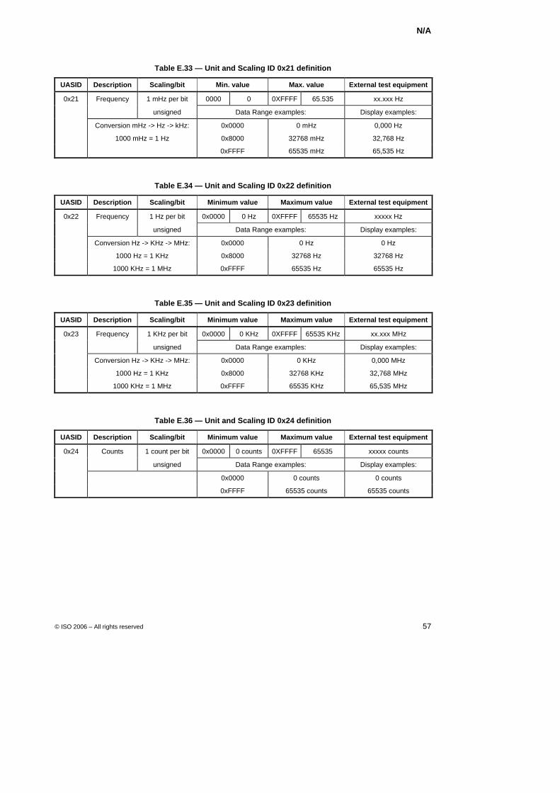
N/A
© ISO 2006 – All rights reserved 57
Table E.33 — Unit and Scaling ID 0x21 definition
UASID Description Scaling/bit Min. value Max. value External test equipment
0x21 Frequency 1 mHz per bit 0000 0 0XFFFF 65.535 xx.xxx Hz
unsigned Data Range examples: Display examples:
Conversion mHz -> Hz -> kHz: 0x0000 0 mHz 0,000 Hz
1000 mHz = 1 Hz 0x8000 32768 mHz 32,768 Hz
0xFFFF 65535 mHz 65,535 Hz
Table E.34 — Unit and Scaling ID 0x22 definition
UASID Description Scaling/bit Minimum value Maximum value External test equipment
0x22 Frequency 1 Hz per bit 0x0000 0 Hz 0XFFFF 65535 Hz xxxxx Hz
unsigned Data Range examples: Display examples:
Conversion Hz -> KHz -> MHz: 0x0000 0 Hz 0 Hz
1000 Hz = 1 KHz 0x8000 32768 Hz 32768 Hz
1000 KHz = 1 MHz 0xFFFF 65535 Hz 65535 Hz
Table E.35 — Unit and Scaling ID 0x23 definition
UASID Description Scaling/bit Minimum value Maximum value External test equipment
0x23 Frequency 1 KHz per bit 0x0000 0 KHz 0XFFFF 65535 KHz xx.xxx MHz
unsigned Data Range examples: Display examples:
Conversion Hz -> KHz -> MHz: 0x0000 0 KHz 0,000 MHz
1000 Hz = 1 KHz 0x8000 32768 KHz 32,768 MHz
1000 KHz = 1 MHz 0xFFFF 65535 KHz 65,535 MHz
Table E.36 — Unit and Scaling ID 0x24 definition
UASID Description Scaling/bit Minimum value Maximum value External test equipment
0x24 Counts 1 count per bit 0x0000 0 counts 0XFFFF 65535 xxxxx counts
unsigned Data Range examples: Display examples:
0x0000 0 counts 0 counts
0xFFFF 65535 counts 65535 counts
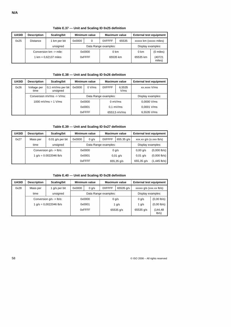
N/A
58 © ISO 2006 – All rights reserved
Table E.37 — Unit and Scaling ID 0x25 definition
UASID Description Scaling/bit Minimum value Maximum value External test equipment
0x25 Distance 1 km per bit 0x0000 0 0XFFFF 65535 xxxxx km (xxxxx miles)
unsigned Data Range examples: Display examples:
Conversion km -> mile: 0x0000 0 km 0 km (0 miles)
1 km = 0,62137 miles 0xFFFF 65535 km 65535 km (40721 miles)
Table E.38 — Unit and Scaling ID 0x26 definition
UASID Description Scaling/bit Minimum value Maximum value External test equipment
0x26 Voltage per time
0,1 mV/ms per bit unsigned
0x0000 0 V/ms 0XFFFF 6,5535 V/ms
xx.xxxx V/ms
Conversion mV/ms -> V/ms: Data Range examples: Display examples:
1000 mV/ms = 1 V/ms 0x0000 0 mV/ms 0,0000 V/ms
0x0001 0,1 mV/ms 0,0001 V/ms
0xFFFF + 6553,5 mV/ms 6,5535 V/ms
Table E.39 — Unit and Scaling ID 0x27 definition
UASID Description Scaling/bit Minimum value Maximum value External test equipment
0x27 Mass per 0.01 g/s per bit 0x0000 0 g/s 0XFFFF 655.35 g/s xxx.xx g/s (x.xxx lb/s)
time unsigned Data Range examples: Display examples:
Conversion g/s -> lb/s: 0x0000 0 g/s 0,00 g/s (0,000 lb/s)
1 g/s = 0.0022046 lb/s 0x0001 + 0,01 g/s 0,01 g/s (0,000 lb/s)
0xFFFF + 655,35 g/s 655,35 g/s (1,445 lb/s)
Table E.40 — Unit and Scaling ID 0x28 definition
UASID Description Scaling/bit Minimum value Maximum value External test equipment
0x28 Mass per 1 g/s per bit 0x0000 0 g/s 0XFFFF 65535 g/s xxxxx g/s (xxx.xx lb/s)
time unsigned Data Range examples: Display examples:
Conversion g/s -> lb/s: 0x0000 0 g/s 0 g/s (0,00 lb/s)
1 g/s = 0,0022046 lb/s 0x0001 + 1 g/s 1 g/s (0,00 lb/s)
0xFFFF + 65535 g/s 65535 g/s (144,48 lb/s)
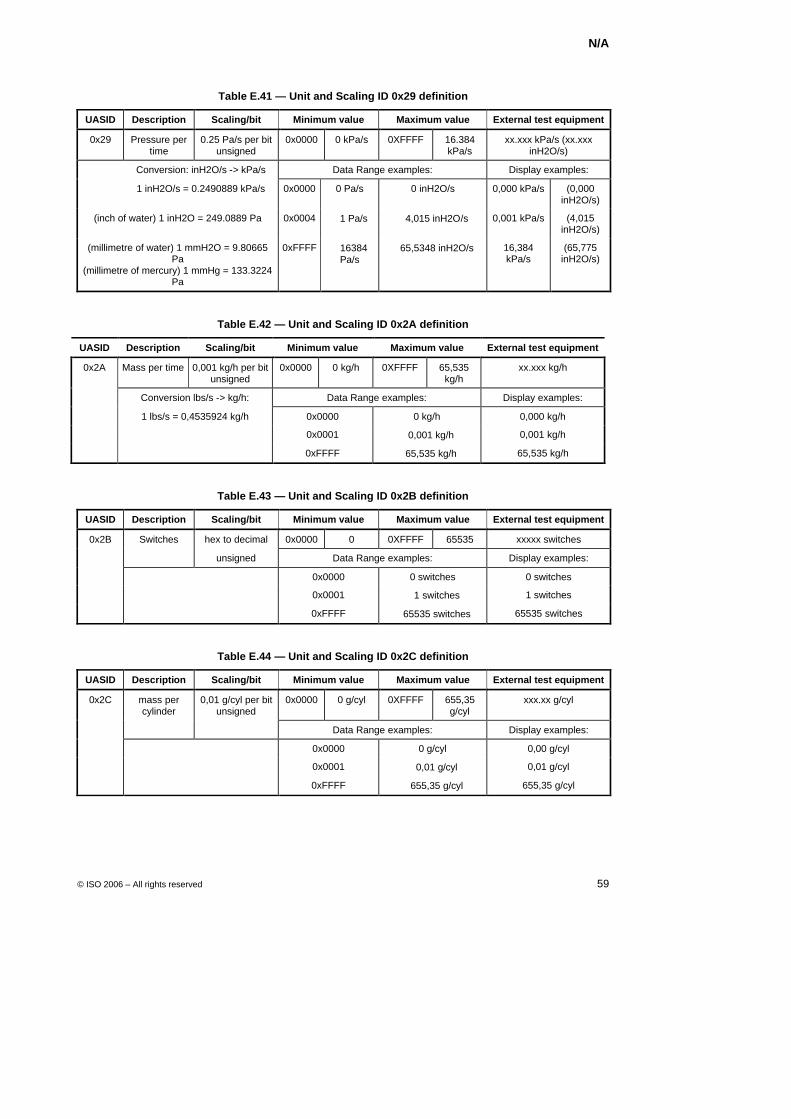
N/A
© ISO 2006 – All rights reserved 59
Table E.41 — Unit and Scaling ID 0x29 definition
UASID Description Scaling/bit Minimum value Maximum value External test equipment
0x29 Pressure per time
0.25 Pa/s per bit unsigned
0x0000 0 kPa/s 0XFFFF 16.384 kPa/s
xx.xxx kPa/s (xx.xxx inH2O/s)
Conversion: inH2O/s -> kPa/s Data Range examples: Display examples:
1 inH2O/s = 0.2490889 kPa/s 0x0000 0 Pa/s 0 inH2O/s 0,000 kPa/s (0,000 inH2O/s)
(inch of water) 1 inH2O = 249.0889 Pa 0x0004 + 1 Pa/s + 4,015 inH2O/s 0,001 kPa/s (4,015 inH2O/s)
(millimetre of water) 1 mmH2O = 9.80665 Pa
(millimetre of mercury) 1 mmHg = 133.3224 Pa
0xFFFF + 16384 Pa/s
+ 65,5348 inH2O/s 16,384 kPa/s
(65,775 inH2O/s)
Table E.42 — Unit and Scaling ID 0x2A definition
UASID Description Scaling/bit Minimum value Maximum value External test equipment
0x2A Mass per time 0,001 kg/h per bit unsigned
0x0000 0 kg/h 0XFFFF 65,535 kg/h
xx.xxx kg/h
Conversion lbs/s -> kg/h: Data Range examples: Display examples:
1 lbs/s = 0,4535924 kg/h 0x0000 0 kg/h 0,000 kg/h
0x0001 + 0,001 kg/h 0,001 kg/h
0xFFFF + 65,535 kg/h 65,535 kg/h
Table E.43 — Unit and Scaling ID 0x2B definition
UASID Description Scaling/bit Minimum value Maximum value External test equipment
0x2B Switches hex to decimal 0x0000 0 0XFFFF 65535 xxxxx switches
unsigned Data Range examples: Display examples:
0x0000 0 switches 0 switches
0x0001 + 1 switches 1 switches
0xFFFF + 65535 switches 65535 switches
Table E.44 — Unit and Scaling ID 0x2C definition
UASID Description Scaling/bit Minimum value Maximum value External test equipment
0x2C 0x0000 0 g/cyl 0XFFFF 655,35 g/cyl
xxx.xx g/cyl
mass per cylinder
0,01 g/cyl per bit unsigned
Data Range examples: Display examples:
0x0000 0 g/cyl 0,00 g/cyl
0x0001 + 0,01 g/cyl 0,01 g/cyl
0xFFFF + 655,35 g/cyl 655,35 g/cyl
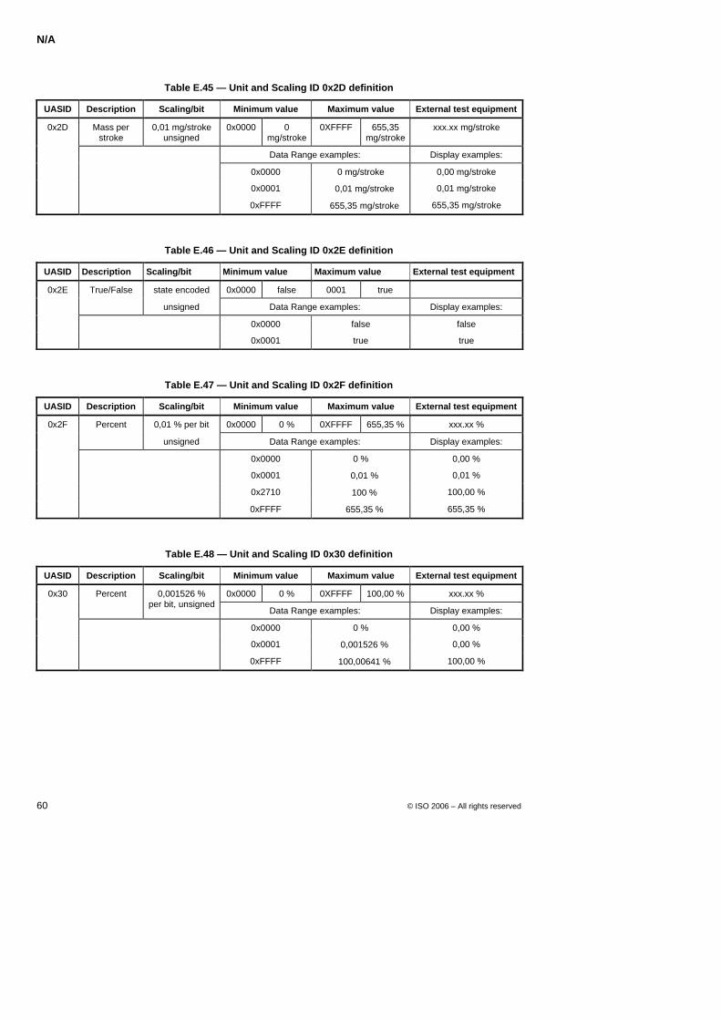
N/A
60 © ISO 2006 – All rights reserved
Table E.45 — Unit and Scaling ID 0x2D definition
UASID Description Scaling/bit Minimum value Maximum value External test equipment
0x2D Mass per stroke
0,01 mg/stroke unsigned
0x0000 0 mg/stroke
0XFFFF 655,35 mg/stroke
xxx.xx mg/stroke
Data Range examples: Display examples:
0x0000 0 mg/stroke 0,00 mg/stroke
0x0001 + 0,01 mg/stroke 0,01 mg/stroke
0xFFFF + 655,35 mg/stroke 655,35 mg/stroke
Table E.46 — Unit and Scaling ID 0x2E definition
UASID Description Scaling/bit Minimum value Maximum value External test equipment
0x2E True/False state encoded 0x0000 false 0001 true
unsigned Data Range examples: Display examples:
0x0000 false false
0x0001 true true
Table E.47 — Unit and Scaling ID 0x2F definition
UASID Description Scaling/bit Minimum value Maximum value External test equipment
0x2F Percent 0,01 % per bit 0x0000 0 % 0XFFFF 655,35 % xxx.xx %
unsigned Data Range examples: Display examples:
0x0000 0 % 0,00 %
0x0001 + 0,01 % 0,01 %
0x2710 + 100 % 100,00 %
0xFFFF + 655,35 % 655,35 %
Table E.48 — Unit and Scaling ID 0x30 definition
UASID Description Scaling/bit Minimum value Maximum value External test equipment
0x30 Percent 0x0000 0 % 0XFFFF 100,00 % xxx.xx %
0,001526 % per bit, unsigned
Data Range examples: Display examples:
0x0000 0 % 0,00 %
0x0001 + 0,001526 % 0,00 %
0xFFFF + 100,00641 % 100,00 %
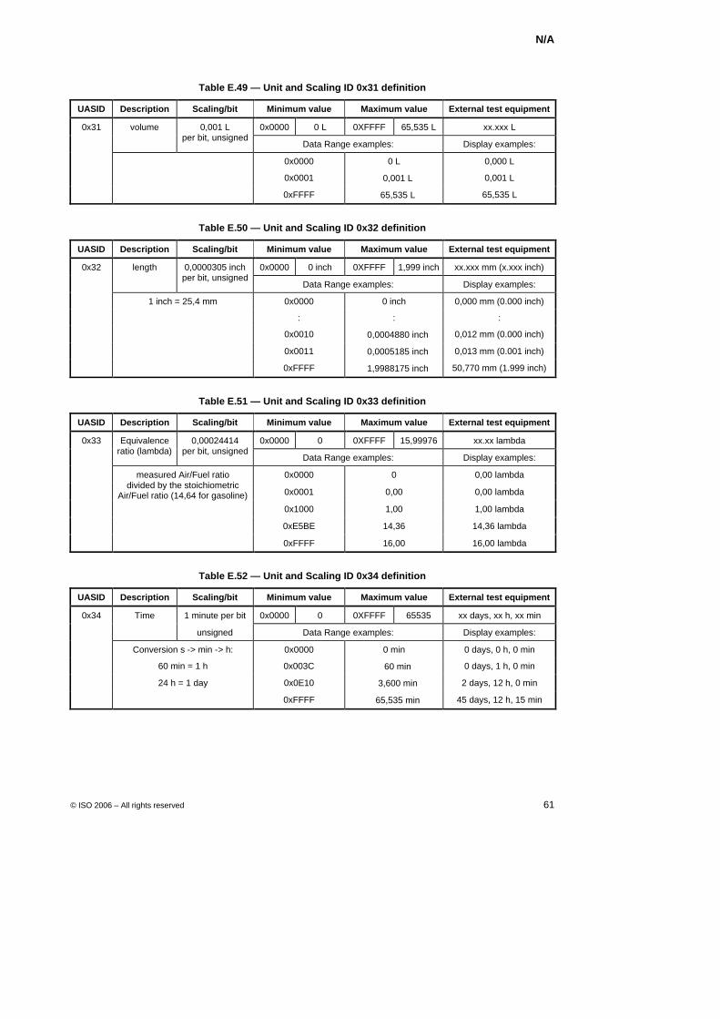
N/A
© ISO 2006 – All rights reserved 61
Table E.49 — Unit and Scaling ID 0x31 definition
UASID Description Scaling/bit Minimum value Maximum value External test equipment
0x31 volume 0x0000 0 L 0XFFFF 65,535 L xx.xxx L
0,001 L per bit, unsigned
Data Range examples: Display examples:
0x0000 0 L 0,000 L
0x0001 + 0,001 L 0,001 L
0xFFFF + 65,535 L 65,535 L
Table E.50 — Unit and Scaling ID 0x32 definition
UASID Description Scaling/bit Minimum value Maximum value External test equipment
0x32 length 0x0000 0 inch 0XFFFF 1,999 inch xx.xxx mm (x.xxx inch)
0,0000305 inch per bit, unsigned
Data Range examples: Display examples:
1 inch = 25,4 mm 0x0000 0 inch 0,000 mm (0.000 inch)
: : :
0x0010 + 0,0004880 inch 0,012 mm (0.000 inch)
0x0011 + 0,0005185 inch 0,013 mm (0.001 inch)
0xFFFF + 1,9988175 inch 50,770 mm (1.999 inch)
Table E.51 — Unit and Scaling ID 0x33 definition
UASID Description Scaling/bit Minimum value Maximum value External test equipment
0x33 0x0000 0 0XFFFF 15,99976 xx.xx lambda
Equivalence ratio (lambda)
0,00024414 per bit, unsigned
Data Range examples: Display examples:
0x0000 0 0,00 lambda
0x0001 0,00 0,00 lambda
0x1000 1,00 1,00 lambda
0xE5BE 14,36 14,36 lambda
measured Air/Fuel ratio divided by the stoichiometric
Air/Fuel ratio (14,64 for gasoline)
0xFFFF 16,00 16,00 lambda
Table E.52 — Unit and Scaling ID 0x34 definition
UASID Description Scaling/bit Minimum value Maximum value External test equipment
0x34 Time 1 minute per bit 0x0000 0 0XFFFF 65535 xx days, xx h, xx min
unsigned Data Range examples: Display examples:
Conversion s -> min -> h: 0x0000 0 min 0 days, 0 h, 0 min
60 min = 1 h 0x003C + 60 min 0 days, 1 h, 0 min
24 h = 1 day 0x0E10 + 3,600 min 2 days, 12 h, 0 min
0xFFFF + 65,535 min 45 days, 12 h, 15 min
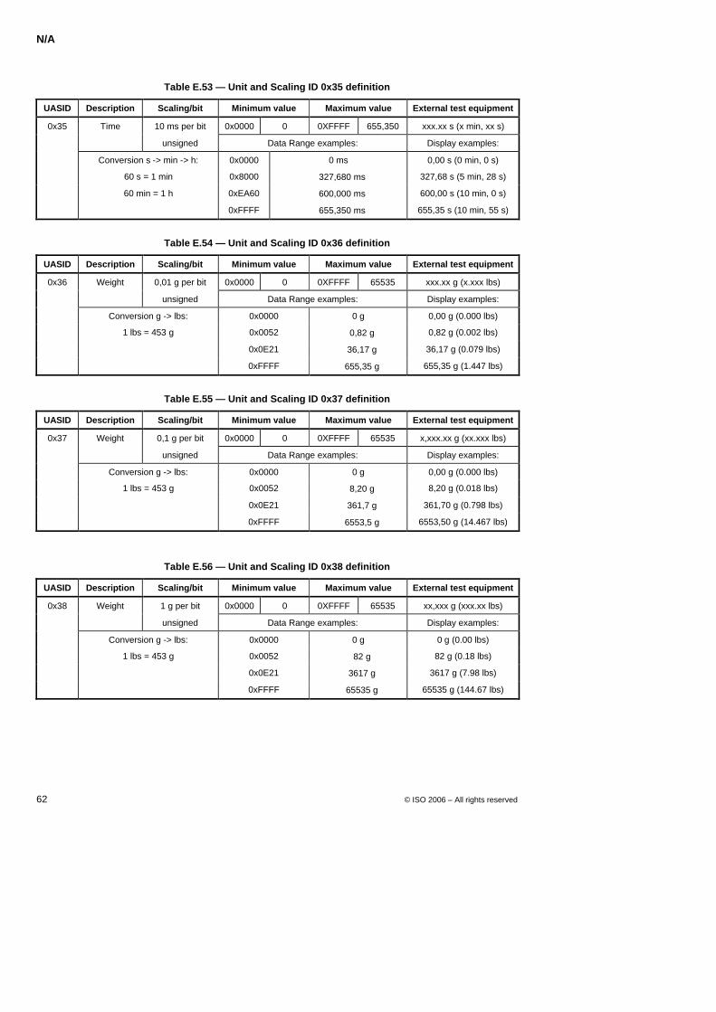
N/A
62 © ISO 2006 – All rights reserved
Table E.53 — Unit and Scaling ID 0x35 definition
UASID Description Scaling/bit Minimum value Maximum value External test equipment
0x35 Time 10 ms per bit 0x0000 0 0XFFFF 655,350 xxx.xx s (x min, xx s)
unsigned Data Range examples: Display examples:
Conversion s -> min -> h: 0x0000 0 ms 0,00 s (0 min, 0 s)
60 s = 1 min 0x8000 + 327,680 ms 327,68 s (5 min, 28 s)
60 min = 1 h 0xEA60 + 600,000 ms 600,00 s (10 min, 0 s)
0xFFFF + 655,350 ms 655,35 s (10 min, 55 s)
Table E.54 — Unit and Scaling ID 0x36 definition
UASID Description Scaling/bit Minimum value Maximum value External test equipment
0x36 Weight 0,01 g per bit 0x0000 0 0XFFFF 65535 xxx.xx g (x.xxx lbs)
unsigned Data Range examples: Display examples:
Conversion g -> lbs: 0x0000 0 g 0,00 g (0.000 lbs)
1 lbs = 453 g 0x0052 + 0,82 g 0,82 g (0.002 lbs)
0x0E21 + 36,17 g 36,17 g (0.079 lbs)
0xFFFF + 655,35 g 655,35 g (1.447 lbs)
Table E.55 — Unit and Scaling ID 0x37 definition
UASID Description Scaling/bit Minimum value Maximum value External test equipment
0x37 Weight 0,1 g per bit 0x0000 0 0XFFFF 65535 x,xxx.xx g (xx.xxx lbs)
unsigned Data Range examples: Display examples:
Conversion g -> lbs: 0x0000 0 g 0,00 g (0.000 lbs)
1 lbs = 453 g 0x0052 + 8,20 g 8,20 g (0.018 lbs)
0x0E21 + 361,7 g 361,70 g (0.798 lbs)
0xFFFF + 6553,5 g 6553,50 g (14.467 lbs)
Table E.56 — Unit and Scaling ID 0x38 definition
UASID Description Scaling/bit Minimum value Maximum value External test equipment
0x38 Weight 1 g per bit 0x0000 0 0XFFFF 65535 xx,xxx g (xxx.xx lbs)
unsigned Data Range examples: Display examples:
Conversion g -> lbs: 0x0000 0 g 0 g (0.00 lbs)
1 lbs = 453 g 0x0052 + 82 g 82 g (0.18 lbs)
0x0E21 + 3617 g 3617 g (7.98 lbs)
0xFFFF + 65535 g 65535 g (144.67 lbs)
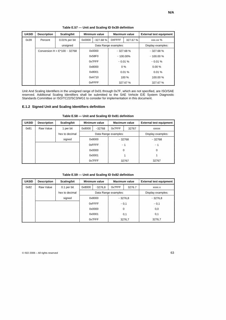
N/A
© ISO 2006 – All rights reserved 63
Table E.57 — Unit and Scaling ID 0x39 definition
UASID Description Scaling/bit Minimum value Maximum value External test equipment
0x39 Percent 0.01% per bit 0x0000 −327.68 % 0XFFFF +327.67 % xxx.xx %
unsigned Data Range examples: Display examples:
Conversion H = E*100 − 32768 0x0000 − 327.68 % − 327.68 %
0x58F0 − 100.00% − 100.00 %
0x7FFF − 0.01 % − 0.01 %
0x8000 0 % 0.00 %
0x8001 + 0.01 % + 0.01 %
0xA710 + 100 % + 100.00 %
0xFFFF + 327.67 % + 327.67 %
Unit And Scaling Identifiers in the unsigned range of 0x01 through 0x7F, which are not specified, are ISO/SAE reserved. Additional Scaling Identifiers shall be submitted to the SAE Vehicle E/E System Diagnostic Standards Committee or ISO/TC22/SC3/WG1 to consider for implementation in this document.
E.1.2 Signed Unit and Scaling Identifiers definition
Table E.58 — Unit and Scaling ID 0x81 definition
UASID Description Scaling/bit Minimum value Maximum value External test equipment
0x81 Raw Value 1 per bit 0x8000 −32768 0x7FFF +32767 xxxxx
hex to decimal Data Range examples: Display examples:
signed 0x8000 − 32768 − 32768
0xFFFF − 1 − 1
0x0000 0 0
0x0001 + 1 1
0x7FFF + 32767 32767
Table E.59 — Unit and Scaling ID 0x82 definition
UASID Description Scaling/bit Minimum value Maximum value External test equipment
0x82 Raw Value 0.1 per bit 0x8000 −3276,8 0x7FFF +3276.7 xxxx.x
hex to decimal Data Range examples: Display examples:
signed 0x8000 − 3276,8 − 3276,8
0xFFFF − 0,1 − 0,1
0x0000 0 0,0
0x0001 + 0,1 0,1
0x7FFF + 3276,7 3276,7
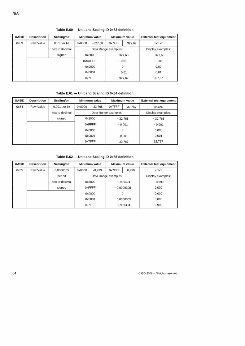
N/A
64 © ISO 2006 – All rights reserved
Table E.60 — Unit and Scaling ID 0x83 definition
UASID Description Scaling/bit Minimum value Maximum value External test equipment
0x83 Raw Value 0,01 per bit 0x8000 −327,68 0x7FFF +327,67 xxx.xx
hex to decimal Data Range examples: Display examples:
signed 0x8000 − 327,68 − 327,68
0x0XFFFF − 0,01 − 0,01
0x0000 0 0,00
0x0001 + 0,01 0,01
0x7FFF + 327,67 327,67
Table E.61 — Unit and Scaling ID 0x84 definition
UASID Description Scaling/bit Minimum value Maximum value External test equipment
0x84 Raw Value 0,001 per bit 0x8000 -32,768 0x7FFF +32,767 xx.xxx
hex to decimal Data Range examples: Display examples:
signed 0x8000 − 32,768 − 32,768
0xFFFF − 0,001 − 0,001
0x0000 0 0,000
0x0001 + 0,001 0,001
0x7FFF + 32,767 32,767
Table E.62 — Unit and Scaling ID 0x85 definition
UASID Description Scaling/bit Minimum value Maximum value External test equipment
0x85 Raw Value 0,0000305 0x8000 -0,999 0x7FFF 0,999 x.xxx
per bit Data Range examples: Display examples:
hex to decimal 0x8000 − 0,999424 − 0,999
signed 0xFFFF − 0,0000305 0,000
0x0000 0 0,000
0x0001 + 0,0000305 0,000
0x7FFF + 0,999394 0,999
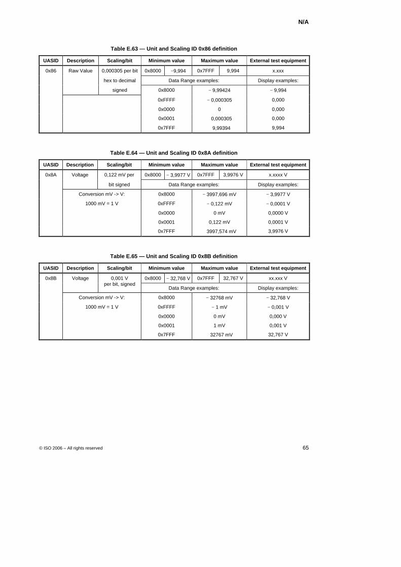
N/A
© ISO 2006 – All rights reserved 65
Table E.63 — Unit and Scaling ID 0x86 definition
UASID Description Scaling/bit Minimum value Maximum value External test equipment
0x86 Raw Value 0,000305 per bit 0x8000 −9,994 0x7FFF 9,994 x.xxx
hex to decimal Data Range examples: Display examples:
signed 0x8000 − 9,99424 − 9,994
0xFFFF − 0,000305 0,000
0x0000 0 0,000
0x0001 + 0,000305 0,000
0x7FFF + 9,99394 9,994
Table E.64 — Unit and Scaling ID 0x8A definition
UASID Description Scaling/bit Minimum value Maximum value External test equipment
0x8A Voltage 0,122 mV per 0x8000 − 3,9977 V 0x7FFF 3,9976 V x.xxxx V
bit signed Data Range examples: Display examples:
Conversion mV -> V: 0x8000 − 3997,696 mV − 3,9977 V
1000 mV = 1 V 0xFFFF − 0,122 mV − 0,0001 V
0x0000 0 mV 0,0000 V
0x0001 0,122 mV 0,0001 V
0x7FFF + 3997,574 mV 3,9976 V
Table E.65 — Unit and Scaling ID 0x8B definition
UASID Description Scaling/bit Minimum value Maximum value External test equipment
0x8B Voltage 0x8000 − 32,768 V 0x7FFF 32,767 V xx.xxx V
0,001 V per bit, signed
Data Range examples: Display examples:
Conversion mV -> V: 0x8000 − 32768 mV − 32,768 V
1000 mV = 1 V 0xFFFF − 1 mV − 0,001 V
0x0000 0 mV 0,000 V
0x0001 1 mV 0,001 V
0x7FFF + 32767 mV 32,767 V
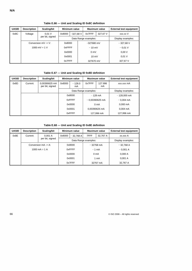
N/A
66 © ISO 2006 – All rights reserved
Table E.66 — Unit and Scaling ID 0x8C definition
UASID Description Scaling/bit Minimum value Maximum value External test equipment
0x8C Voltage 0x8000 −327,68 V 0x7FFF 327,67 V xxx.xx V
0,01 V per bit, signed
Data Range examples: Display examples:
Conversion mV -> V: 0x8000 −327680 mV − 327,68 V
1000 mV = 1 V 0xFFFF − 10 mV − 0,01 V
0x0000 0 mV 0,00 V
0x0001 + 10 mV 0,01 V
0x7FFF +327670 mV 327,67 V
Table E.67 — Unit and Scaling ID 0x8D definition
UASID Description Scaling/bit Minimum value Maximum value External test equipment
0x8D Current 0x8000 − 128.0 mA
0x7FFF 127.996 mA
xxx.xxx mA
0,00390625 mA per bit, signed
Data Range examples: Display examples:
0x8000 − 128 mA − 128,000 mA
0xFFFF − 0,00390625 mA − 0,004 mA
0x0000 + 0 mA 0,000 mA
0x0001 0,00390625 mA 0,004 mA
0xFFFF + 127,996 mA 127,996 mA
Table E.68 — Unit and Scaling ID 0x8E definition
UASID Description Scaling/bit Minimum value Maximum value External test equipment
0x8E Current 0x8000 − 32,768 A 7FFF 32,767 A xx.xxx A
0,001 A per bit, signed
Data Range examples: Display examples:
Conversion mA -> A: 0x8000 − 32768 mA − 32,768 A
1000 mA = 1 A 0xFFFF − 1 mA − 0,001 A
0x0000 0 mA 0,000 A
0x0001 + 1 mA 0,001 A
0x7FFF + 32767 mA 32,767 A

N/A
© ISO 2006 – All rights reserved 67
Table E.69 — Unit and Scaling ID 0x90 definition
UASID Description Scaling/bit Minimum value Maximum value External test equipment
0x90 Time 0x8000 − 32,768 s 0x7FFF + 32,767 s xx.xxx s
1 ms per bit, signed
Data Range examples: Display examples:
0x8000 − 32768 ms − 32,768 s
0x0001 + 1 ms + 0,001 s
0x7FFF + 32767 ms + 32,767 s
Table E.70 — Unit and Scaling ID 0x96 definition
UASID Description Scaling/bit Minimum value Maximum value External test equipment
0x96 Temperature 0x8000 −3276,8 °C
0x7FFF +3276,7 °C
xxxx.x °C (xxxx.x °F)
0,1 °C per bit, signed
Data Range examples: Display examples:
Conversion °C -> °F: 0x8000 − 3276,8 °C − 3276,8 °C (− 5886,2 °F)
°F = °C * 1.8 + 32 °C 0xFE70 − 40 °C − 40,0 °C (− 40,0 °F)
0xFFFF − 0,1 °C -0,1 °C (31,8 °F)
0x0000 0 °C 0,0 °C (32,0 °F)
0x0001° + 0,1 °C 0,1 °C (32,2 °F)
0x4E20° + 2000 °C 2000,0 °C (3632,0 °F)
0x7FFF° + 3276,7 °C 3276,7 °C (5930,1 °F)
Table E.71 — Unit and Scaling ID 0x9C definition
UASID Description Scaling/bit Minimum value Maximum value External test equipment
0x9C Angle 0x8000 − 327,68 ° 0x7FFF 327,67 ° xxx.xx °
0,01° per bit, signed
Data Range examples: Display examples:
0x8000 − 327,68 ° − 327,68 °
0xF060 − 40 ° − 40,00 °
0xFFFF − 0,01 ° − 0,01 °
0x0000 0 ° 0,00 °
0x0FA0 + 40 ° + 40,00 °
0x7FFF + 327,67 ° + 327,67 °
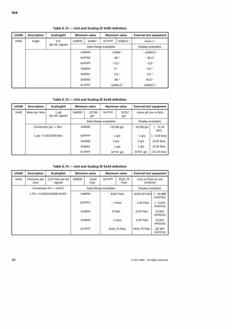
N/A
68 © ISO 2006 – All rights reserved
Table E.72 — Unit and Scaling ID 0x9D definition
UASID Description Scaling/bit Minimum value Maximum value External test equipment
0x9D Angle 0x8000 -16384 ° 0x7FFF 16383,5 ° xxxxx.x °
0,5° per bit, signed
Data Range examples: Display examples:
0x8000 − 16384 ° − 16384,0 °
0xFF60 − 80 ° − 80,0 °
0xFFFF − 0,5 ° − 0,5 °
0x0000 0 ° 0,0 °
0x0001 + 0,5 ° 0,5 °
0x00A0 + 80 ° 80,0 °
0x7FFF + 16383,5 ° 16383,5 °
Table E.73 — Unit and Scaling ID 0xA8 definition
UASID Description Scaling/bit Minimum value Maximum value External test equipment
0xA8 0x8000 − 32768 g/s
0x7FFF + 32767 g/s
xxxxx g/s (xx.xx lb/s)
Mass per time 1 g/s per bit, signed
Data Range examples: Display examples:
Conversion g/s -> lb/s: 0x8000 − 32768 g/s − 32768 g/s (− 72.24 lb/s)
1 g/s = 0.0022046 lb/s 0xFFFF − 1 g/s − 1 g/s (− 0.00 lb/s)
0x0000 0 g/s 0 g/s (0.00 lb/s)
0x0001 + 1 g/s 1 g/s (0.00 lb/s)
0x7FFF + 32767 g/s 32767 g/s (72.24 lb/s)
Table E.74 — Unit and Scaling ID 0xA9 definition
UASID Description Scaling/bit Minimum value Maximum value External test equipment
0xA9 Pressure per time
0,25 Pa/s per bit signed
0x8000 − 8192 Pa/s
0x7FFF 8191,75 Pa/s
xxxx.xx Pa/s (xx.xxx inH2O/s)
Conversion Pa -> inH2O Data Range examples: Display examples:
1 Pa = 0.0040146309 inH2O 0x8000 − 8192 Pa/s − 8192,00 Pa/s (− 32,888 inH2O/s)
0xFFFC − 1 Pa/s − 1,00 Pa/s (− 0,004 inH2O/s)
0x0000 0 Pa/s 0,00 Pa/s (0,000 inH2O/s)
0x0004 + 1 Pa/s 1,00 Pa/s (0,004 inH2O/s)
0x7FFF + 8191,75 Pa/s 8191,75 Pa/s (32,887 inH2O/s)
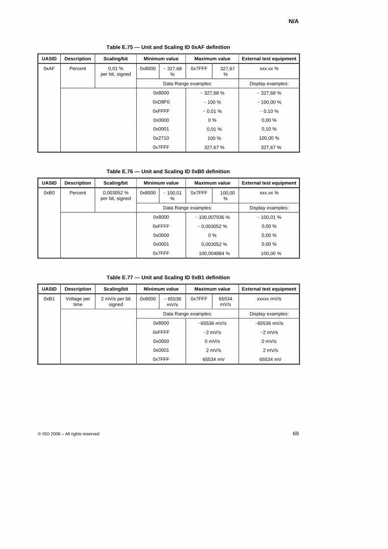
N/A
© ISO 2006 – All rights reserved 69
Table E.75 — Unit and Scaling ID 0xAF definition
UASID Description Scaling/bit Minimum value Maximum value External test equipment
0xAF Percent 0x8000 − 327,68 %
0x7FFF + 327,67 %
xxx.xx %
0,01 % per bit, signed
Data Range examples: Display examples:
0x8000 − 327,68 % − 327,68 %
0xD8F0 − 100 % − 100,00 %
0xFFFF − 0,01 % − 0,10 %
0x0000 0 % 0,00 %
0x0001 + 0,01 % 0,10 %
0x2710 + 100 % 100,00 %
0x7FFF + 327,67 % + 327,67 %
Table E.76 — Unit and Scaling ID 0xB0 definition
UASID Description Scaling/bit Minimum value Maximum value External test equipment
0xB0 Percent 0x8000 − 100,01 %
0x7FFF + 100,00 %
xxx.xx %
0,003052 % per bit, signed
Data Range examples: Display examples:
0x8000 − 100,007936 % − 100,01 %
0xFFFF − 0,003052 % 0,00 %
0x0000 0 % 0,00 %
0x0001 + 0,003052 % 0,00 %
0x7FFF + 100,004884 % + 100,00 %
Table E.77 — Unit and Scaling ID 0xB1 definition
UASID Description Scaling/bit Minimum value Maximum value External test equipment
0xB1 Voltage per time
2 mV/s per bit signed
0x8000 − 65536 mV/s
0x7FFF 65534 mV/s
xxxxx mV/s
Data Range examples: Display examples:
0x8000 −65536 mV/s −65536 mV/s
0xFFFF −2 mV/s −2 mV/s
0x0000 0 mV/s 0 mV/s
0x0001 +2 mV/s +2 mV/s
0x7FFF +65534 mV +65534 mV
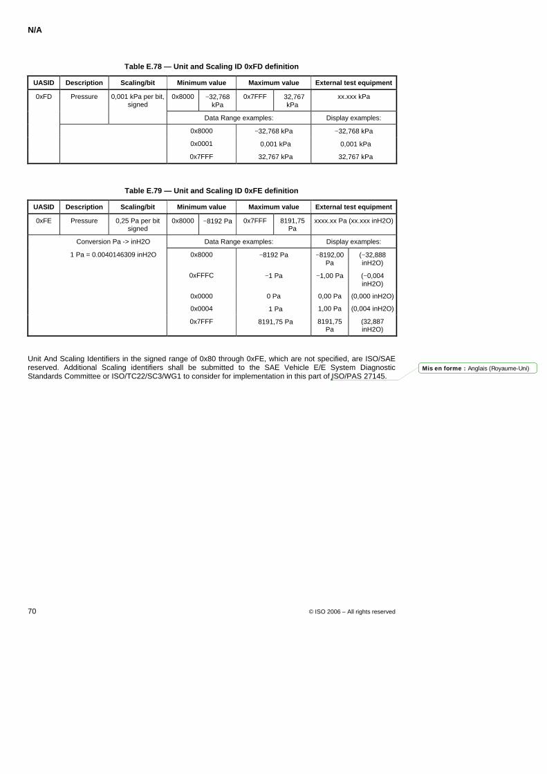
N/A
70 © ISO 2006 – All rights reserved
Table E.78 — Unit and Scaling ID 0xFD definition
UASID Description Scaling/bit Minimum value Maximum value External test equipment
0xFD Pressure 0,001 kPa per bit, signed
0x8000 −32,768 kPa
0x7FFF +32,767 kPa
xx.xxx kPa
Data Range examples: Display examples:
0x8000 −32,768 kPa −32,768 kPa
0x0001 +0,001 kPa +0,001 kPa
0x7FFF +32,767 kPa +32,767 kPa
Table E.79 — Unit and Scaling ID 0xFE definition
UASID Description Scaling/bit Minimum value Maximum value External test equipment
0xFE Pressure 0,25 Pa per bit signed
0x8000 −8192 Pa 0x7FFF 8191,75 Pa
xxxx.xx Pa (xx.xxx inH2O)
Conversion Pa -> inH2O Data Range examples: Display examples:
1 Pa = 0.0040146309 inH2O 0x8000 −8192 Pa −8192,00 Pa
(−32,888 inH2O)
0xFFFC −1 Pa −1,00 Pa (−0,004 inH2O)
0x0000 0 Pa 0,00 Pa (0,000 inH2O)
0x0004 +1 Pa 1,00 Pa (0,004 inH2O)
0x7FFF +8191,75 Pa 8191,75 Pa
(32,887 inH2O)
Unit And Scaling Identifiers in the signed range of 0x80 through 0xFE, which are not specified, are ISO/SAE reserved. Additional Scaling identifiers shall be submitted to the SAE Vehicle E/E System Diagnostic Standards Committee or ISO/TC22/SC3/WG1 to consider for implementation in this part of ISO/PAS 27145.
Mis en forme : Anglais (Royaume-Uni)
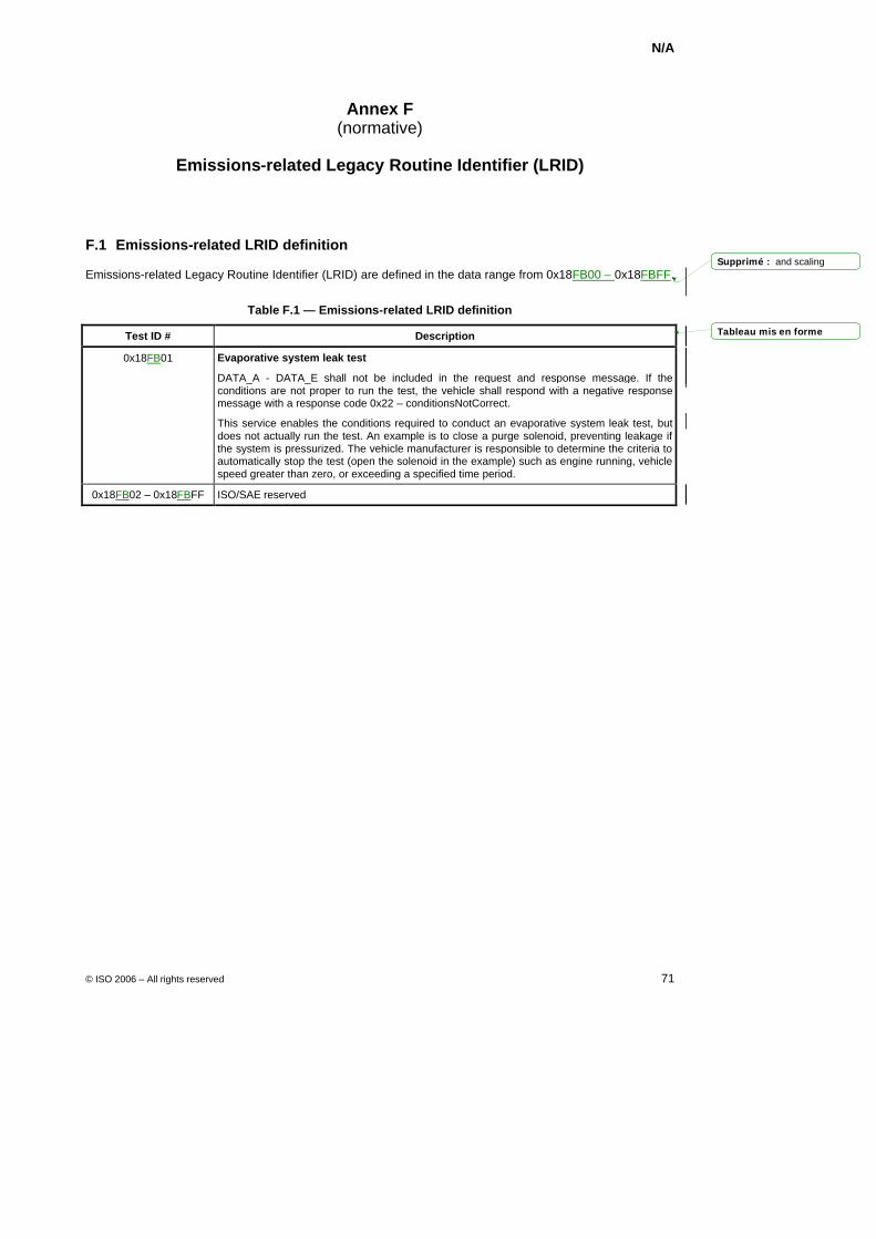
N/A
© ISO 2006 – All rights reserved 71
Annex F (normative)
Emissions-related Legacy Routine Identifier (LRID)
F.1 Emissions-related LRID definition
Emissions-related Legacy Routine Identifier (LRID) are defined in the data range from 0x18FB00 – 0x18FBFF.
Table F.1 — Emissions-related LRID definition
Test ID # Description
0x18FB01 Evaporative system leak test
DATA_A - DATA_E shall not be included in the request and response message. If the conditions are not proper to run the test, the vehicle shall respond with a negative response message with a response code 0x22 – conditionsNotCorrect.
This service enables the conditions required to conduct an evaporative system leak test, but does not actually run the test. An example is to close a purge solenoid, preventing leakage if the system is pressurized. The vehicle manufacturer is responsible to determine the criteria to automatically stop the test (open the solenoid in the example) such as engine running, vehicle speed greater than zero, or exceeding a specified time period.
0x18FB02 – 0x18FBFF ISO/SAE reserved
Tableau mis en forme
Supprimé : and scaling
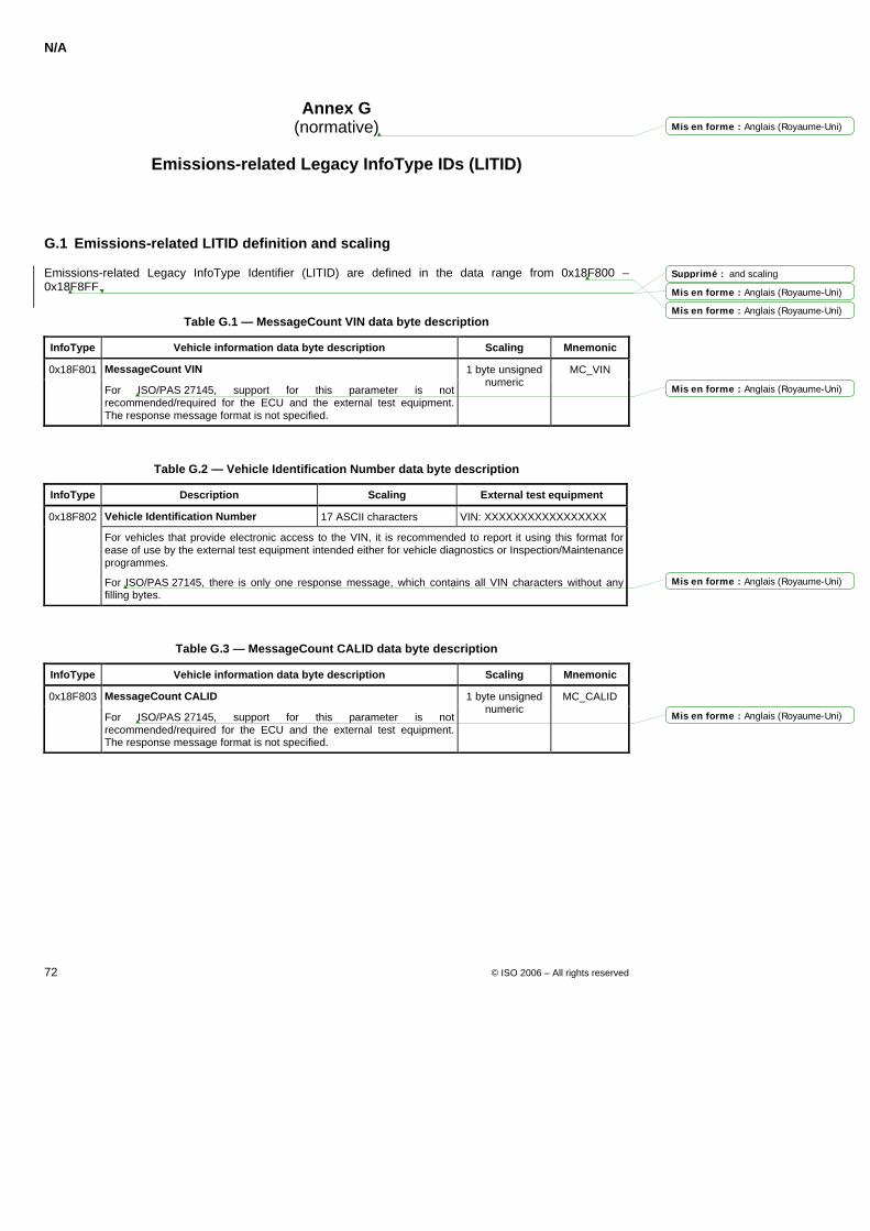
N/A
72 © ISO 2006 – All rights reserved
Annex G (normative)
Emissions-related Legacy InfoType IDs (LITID)
G.1 Emissions-related LITID definition and scaling
Emissions-related Legacy InfoType Identifier (LITID) are defined in the data range from 0x18F800 – 0x18F8FF.
Table G.1 — MessageCount VIN data byte description
InfoType Vehicle information data byte description Scaling Mnemonic
0x18F801 MessageCount VIN
For ISO/PAS 27145, support for this parameter is not recommended/required for the ECU and the external test equipment. The response message format is not specified.
1 byte unsigned numeric
MC_VIN
Table G.2 — Vehicle Identification Number data byte description
InfoType Description Scaling External test equipment
0x18F802 Vehicle Identification Number 17 ASCII characters VIN: XXXXXXXXXXXXXXXXX
For vehicles that provide electronic access to the VIN, it is recommended to report it using this format for ease of use by the external test equipment intended either for vehicle diagnostics or Inspection/Maintenance programmes.
For ISO/PAS 27145, there is only one response message, which contains all VIN characters without any filling bytes.
Table G.3 — MessageCount CALID data byte description
InfoType Vehicle information data byte description Scaling Mnemonic
0x18F803 MessageCount CALID MC_CALID
For ISO/PAS 27145, support for this parameter is not recommended/required for the ECU and the external test equipment. The response message format is not specified.
1 byte unsigned numeric
Mis en forme : Anglais (Royaume-Uni)
Mis en forme : Anglais (Royaume-Uni)
Mis en forme : Anglais (Royaume-Uni)
Mis en forme : Anglais (Royaume-Uni)
Mis en forme : Anglais (Royaume-Uni)
Mis en forme : Anglais (Royaume-Uni)
Supprimé : and scaling
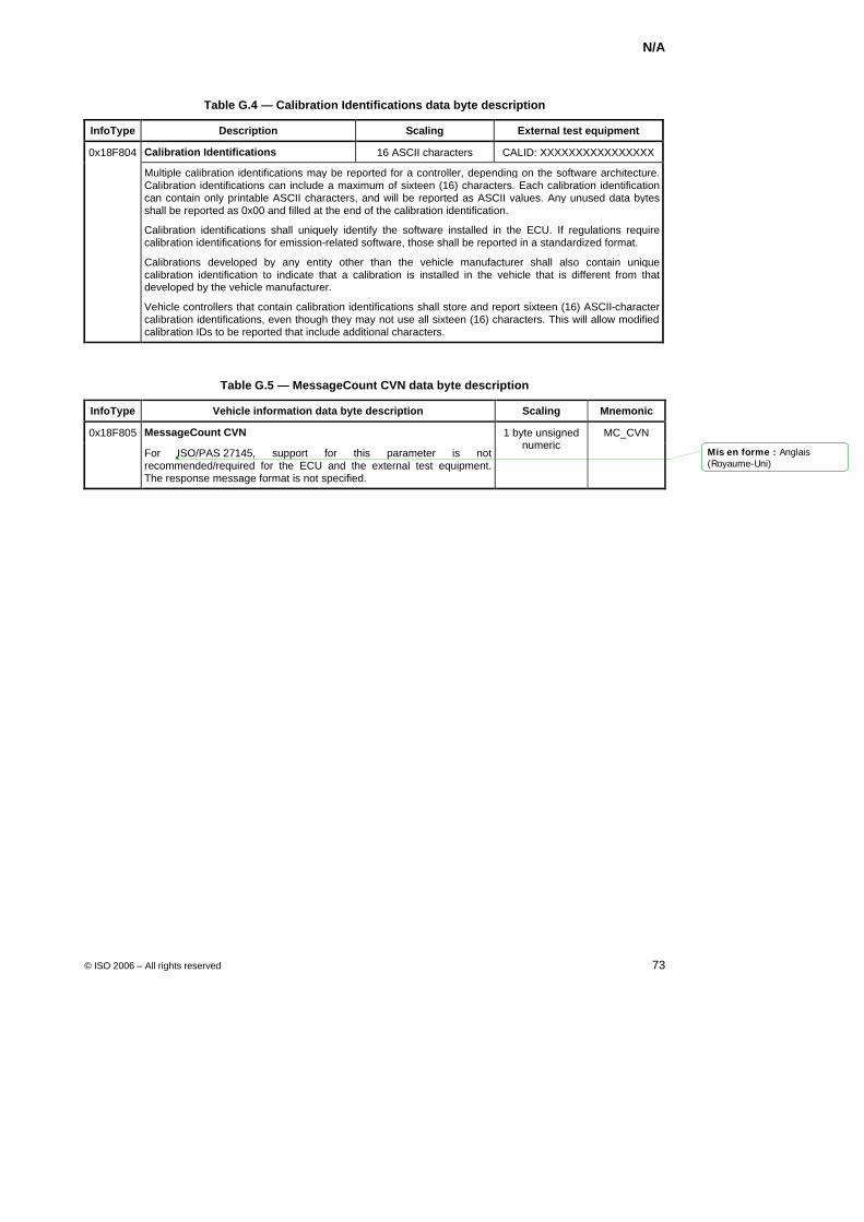
N/A
© ISO 2006 – All rights reserved 73
Table G.4 — Calibration Identifications data byte description
InfoType Description Scaling External test equipment
0x18F804 Calibration Identifications 16 ASCII characters CALID: XXXXXXXXXXXXXXXX
Multiple calibration identifications may be reported for a controller, depending on the software architecture. Calibration identifications can include a maximum of sixteen (16) characters. Each calibration identification can contain only printable ASCII characters, and will be reported as ASCII values. Any unused data bytes shall be reported as 0x00 and filled at the end of the calibration identification.
Calibration identifications shall uniquely identify the software installed in the ECU. If regulations require calibration identifications for emission-related software, those shall be reported in a standardized format.
Calibrations developed by any entity other than the vehicle manufacturer shall also contain unique calibration identification to indicate that a calibration is installed in the vehicle that is different from that developed by the vehicle manufacturer.
Vehicle controllers that contain calibration identifications shall store and report sixteen (16) ASCII-character calibration identifications, even though they may not use all sixteen (16) characters. This will allow modified calibration IDs to be reported that include additional characters.
Table G.5 — MessageCount CVN data byte description
InfoType Vehicle information data byte description Scaling Mnemonic
0x18F805 MessageCount CVN MC_CVN
For ISO/PAS 27145, support for this parameter is not recommended/required for the ECU and the external test equipment. The response message format is not specified.
1 byte unsigned numeric
Mis en forme : Anglais(Royaume-Uni)
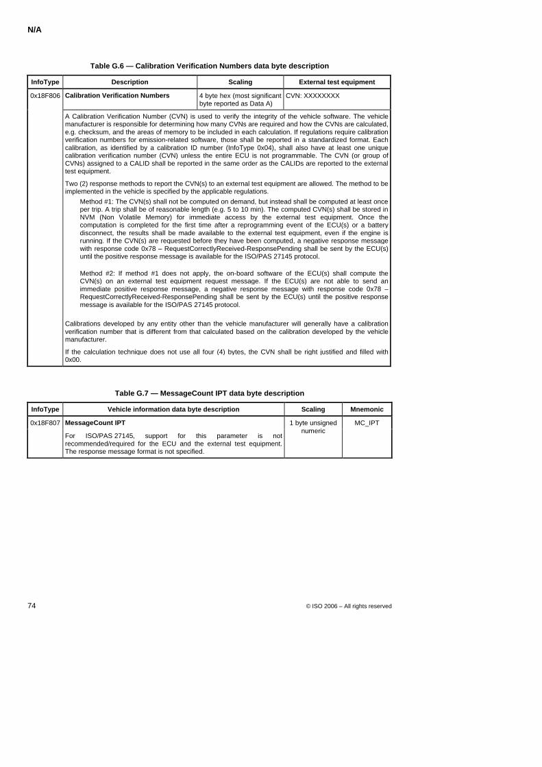
N/A
74 © ISO 2006 – All rights reserved
Table G.6 — Calibration Verification Numbers data byte description
InfoType Description Scaling External test equipment
0x18F806 Calibration Verification Numbers 4 byte hex (most significant byte reported as Data A)
CVN: XXXXXXXX
A Calibration Verification Number (CVN) is used to verify the integrity of the vehicle software. The vehicle manufacturer is responsible for determining how many CVNs are required and how the CVNs are calculated, e.g. checksum, and the areas of memory to be included in each calculation. If regulations require calibration verification numbers for emission-related software, those shall be reported in a standardized format. Each calibration, as identified by a calibration ID number (InfoType 0x04), shall also have at least one unique calibration verification number (CVN) unless the entire ECU is not programmable. The CVN (or group of CVNs) assigned to a CALID shall be reported in the same order as the CALIDs are reported to the external test equipment.
Two (2) response methods to report the CVN(s) to an external test equipment are allowed. The method to be implemented in the vehicle is specified by the applicable regulations. Method #1: The CVN(s) shall not be computed on demand, but instead shall be computed at least once
per trip. A trip shall be of reasonable length (e.g. 5 to 10 min). The computed CVN(s) shall be stored in NVM (Non Volatile Memory) for immediate access by the external test equipment. Once the computation is completed for the first time after a reprogramming event of the ECU(s) or a battery disconnect, the results shall be made available to the external test equipment, even if the engine is running. If the CVN(s) are requested before they have been computed, a negative response message with response code 0x78 – RequestCorrectlyReceived-ResponsePending shall be sent by the ECU(s) until the positive response message is available for the ISO/PAS 27145 protocol.
Method #2: If method #1 does not apply, the on-board software of the ECU(s) shall compute the CVN(s) on an external test equipment request message. If the ECU(s) are not able to send an immediate positive response message, a negative response message with response code 0x78 – RequestCorrectlyReceived-ResponsePending shall be sent by the ECU(s) until the positive response message is available for the ISO/PAS 27145 protocol.
Calibrations developed by any entity other than the vehicle manufacturer will generally have a calibration verification number that is different from that calculated based on the calibration developed by the vehicle manufacturer.
If the calculation technique does not use all four (4) bytes, the CVN shall be right justified and filled with 0x00.
Table G.7 — MessageCount IPT data byte description
InfoType Vehicle information data byte description Scaling Mnemonic
0x18F807 MessageCount IPT
For ISO/PAS 27145, support for this parameter is not recommended/required for the ECU and the external test equipment. The response message format is not specified.
1 byte unsigned numeric
MC_IPT
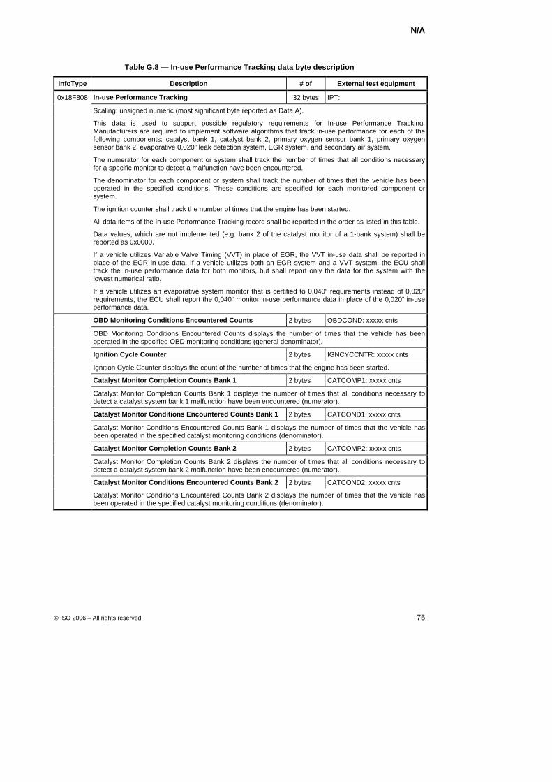
N/A
© ISO 2006 – All rights reserved 75
Table G.8 — In-use Performance Tracking data byte description
InfoType Description # of External test equipment
0x18F808 In-use Performance Tracking 32 bytes IPT:
Scaling: unsigned numeric (most significant byte reported as Data A).
This data is used to support possible regulatory requirements for In-use Performance Tracking. Manufacturers are required to implement software algorithms that track in-use performance for each of the following components: catalyst bank 1, catalyst bank 2, primary oxygen sensor bank 1, primary oxygen sensor bank 2, evaporative 0,020” leak detection system, EGR system, and secondary air system.
The numerator for each component or system shall track the number of times that all conditions necessary for a specific monitor to detect a malfunction have been encountered.
The denominator for each component or system shall track the number of times that the vehicle has been operated in the specified conditions. These conditions are specified for each monitored component or system.
The ignition counter shall track the number of times that the engine has been started.
All data items of the In-use Performance Tracking record shall be reported in the order as listed in this table.
Data values, which are not implemented (e.g. bank 2 of the catalyst monitor of a 1-bank system) shall be reported as 0x0000.
If a vehicle utilizes Variable Valve Timing (VVT) in place of EGR, the VVT in-use data shall be reported in place of the EGR in-use data. If a vehicle utilizes both an EGR system and a VVT system, the ECU shall track the in-use performance data for both monitors, but shall report only the data for the system with the lowest numerical ratio.
If a vehicle utilizes an evaporative system monitor that is certified to 0,040“ requirements instead of 0,020” requirements, the ECU shall report the 0,040“ monitor in-use performance data in place of the 0,020” in-use performance data.
OBD Monitoring Conditions Encountered Counts 2 bytes OBDCOND: xxxxx cnts
OBD Monitoring Conditions Encountered Counts displays the number of times that the vehicle has been operated in the specified OBD monitoring conditions (general denominator).
Ignition Cycle Counter 2 bytes IGNCYCCNTR: xxxxx cnts
Ignition Cycle Counter displays the count of the number of times that the engine has been started.
Catalyst Monitor Completion Counts Bank 1 2 bytes CATCOMP1: xxxxx cnts
Catalyst Monitor Completion Counts Bank 1 displays the number of times that all conditions necessary to detect a catalyst system bank 1 malfunction have been encountered (numerator).
Catalyst Monitor Conditions Encountered Counts Bank 1 2 bytes CATCOND1: xxxxx cnts
Catalyst Monitor Conditions Encountered Counts Bank 1 displays the number of times that the vehicle has been operated in the specified catalyst monitoring conditions (denominator).
Catalyst Monitor Completion Counts Bank 2 2 bytes CATCOMP2: xxxxx cnts
Catalyst Monitor Completion Counts Bank 2 displays the number of times that all conditions necessary to detect a catalyst system bank 2 malfunction have been encountered (numerator).
Catalyst Monitor Conditions Encountered Counts Bank 2 2 bytes CATCOND2: xxxxx cnts
Catalyst Monitor Conditions Encountered Counts Bank 2 displays the number of times that the vehicle has been operated in the specified catalyst monitoring conditions (denominator).
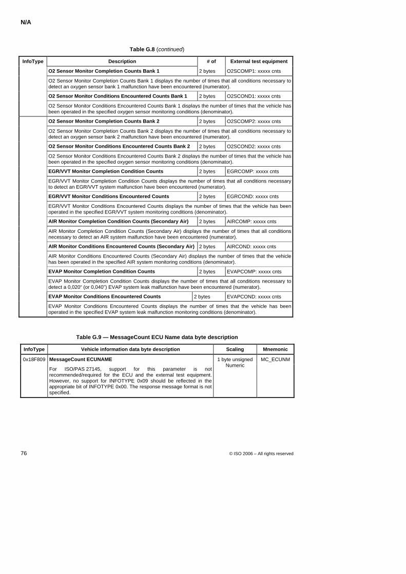
N/A
76 © ISO 2006 – All rights reserved
Table G.8 (continued)
InfoType Description # of External test equipment
O2 Sensor Monitor Completion Counts Bank 1 2 bytes O2SCOMP1: xxxxx cnts
O2 Sensor Monitor Completion Counts Bank 1 displays the number of times that all conditions necessary to detect an oxygen sensor bank 1 malfunction have been encountered (numerator).
O2 Sensor Monitor Conditions Encountered Counts Bank 1 2 bytes O2SCOND1: xxxxx cnts
O2 Sensor Monitor Conditions Encountered Counts Bank 1 displays the number of times that the vehicle has been operated in the specified oxygen sensor monitoring conditions (denominator).
O2 Sensor Monitor Completion Counts Bank 2 2 bytes O2SCOMP2: xxxxx cnts
O2 Sensor Monitor Completion Counts Bank 2 displays the number of times that all conditions necessary to detect an oxygen sensor bank 2 malfunction have been encountered (numerator).
O2 Sensor Monitor Conditions Encountered Counts Bank 2 2 bytes O2SCOND2: xxxxx cnts
O2 Sensor Monitor Conditions Encountered Counts Bank 2 displays the number of times that the vehicle has been operated in the specified oxygen sensor monitoring conditions (denominator).
EGR/VVT Monitor Completion Condition Counts 2 bytes EGRCOMP: xxxxx cnts
EGR/VVT Monitor Completion Condition Counts displays the number of times that all conditions necessary to detect an EGR/VVT system malfunction have been encountered (numerator).
EGR/VVT Monitor Conditions Encountered Counts 2 bytes EGRCOND: xxxxx cnts
EGR/VVT Monitor Conditions Encountered Counts displays the number of times that the vehicle has been operated in the specified EGR/VVT system monitoring conditions (denominator).
AIR Monitor Completion Condition Counts (Secondary Air) 2 bytes AIRCOMP: xxxxx cnts
AIR Monitor Completion Condition Counts (Secondary Air) displays the number of times that all conditions necessary to detect an AIR system malfunction have been encountered (numerator).
AIR Monitor Conditions Encountered Counts (Secondary Air) 2 bytes AIRCOND: xxxxx cnts
AIR Monitor Conditions Encountered Counts (Secondary Air) displays the number of times that the vehicle has been operated in the specified AIR system monitoring conditions (denominator).
EVAP Monitor Completion Condition Counts 2 bytes EVAPCOMP: xxxxx cnts
EVAP Monitor Completion Condition Counts displays the number of times that all conditions necessary to detect a 0,020“ (or 0,040”) EVAP system leak malfunction have been encountered (numerator).
EVAP Monitor Conditions Encountered Counts 2 bytes EVAPCOND: xxxxx cnts
EVAP Monitor Conditions Encountered Counts displays the number of times that the vehicle has been operated in the specified EVAP system leak malfunction monitoring conditions (denominator).
Table G.9 — MessageCount ECU Name data byte description
InfoType Vehicle information data byte description Scaling Mnemonic
0x18F809 MessageCount ECUNAME
For ISO/PAS 27145, support for this parameter is not recommended/required for the ECU and the external test equipment. However, no support for INFOTYPE 0x09 should be reflected in the appropriate bit of INFOTYPE 0x00. The response message format is not specified.
1 byte unsigned Numeric
MC_ECUNM
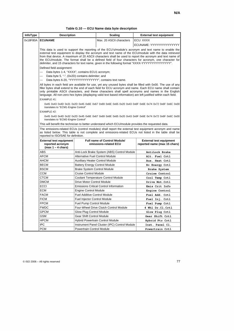
N/A
© ISO 2006 – All rights reserved 77
Table G.10 — ECU Name data byte description
InfoType Description Scaling External test equipment
0x18F80A ECUNAME Max. 20 ASCII characters ECU: XXXX
ECUNAME: YYYYYYYYYYYYYYY
This data is used to support the reporting of the ECU’s/module’s acronym and text name to enable the external test equipment to display the acronym and text name of the ECU/module with the data retrieved from that device. A maximum of 20 ASCII characters shall be used to report the acronym and text name of the ECU/module. The format shall be a defined field of four characters for acronym, one character for delimiter, and 15 characters for text name, given in the following format “XXXX-YYYYYYYYYYYYYYY”.
Defined field assignment: — Data bytes 1-4, “XXXX”, contains ECU1 acronym; — Data byte 5, “-”, (0x2D) contains delimiter; and — Data bytes 6-20, “YYYYYYYYYYYYYYY”, contains text name.
All bytes in each field are available for use, yet any unused bytes shall be filled with 0x00. The use of any filler bytes shall extend to the end of each field for ECU acronym and name. Each ECU name shall contain only printable ASCII characters, and these characters shall spell acronyms and names in the English language. All non-zero hex bytes (displaying valid text based information) are left justified within each field.
EXAMPLE #1:
0x45 0x43 0x4D 0x31 0x2D 0x45 0x6E 0x67 0x69 0x6E 0x65 0x20 0x43 0x6F 0x6E 0x74 0x72 0x6F 0x6C 0x00 translates to “ECM1-Engine Control”
EXAMPLE #2:
0x45 0x43 0x4D 0x32 0x2D 0x45 0x6E 0x67 0x69 0x6E 0x65 0x20 0x43 0x6F 0x6E 0x74 0x72 0x6F 0x6C 0x00 translates to “ECM2-Engine Control”
This will benefit the technician to better understand which ECU/module provides the requested data.
The emissions-related ECUs (control modules) shall report the external test equipment acronym and name as listed below. This table is not complete and emissions-related ECUs not listed in the table shall be reported to ISO/SAE for definition.
External test equipment reported acronym (max 1 – 4 chars)
Full name of Control Module/ emissions-related ECU
External test equipment reported name (max 15 chars)
ABS Anti-Lock Brake System (ABS) Control Module AntiLock Brake AFCM Alternative Fuel Control Module Alt. Fuel Crtl AHCM Auxiliary Heater Control Module Aux. Heat Crtl BECM Battery Energy Control Module B+ Energy Crtl BSCM Brake System Control Module Brake System CCM Cruise Control Module Cruise Control CTCM Coolant Temperature Control Module Cool Temp Crtl DMCM Drive Motor Control Module Drive Mot.Crtl ECCI Emissions Critical Control Information Emis Crit Info ECM Engine Control Module Engine Control FACM Fuel Additive Control Module Fuel Add. Crtl FICM Fuel Injector Control Module Fuel Inj. Crtl FPCM Fuel Pump Control Module Fuel Pump Crtl FWDC Four-Wheel Drive Clutch Control Module 4 Whl Dr.Cl.Crtl GPCM Glow Plug Control Module Glow Plug Crtl GSM Gear Shift Control Module Gear Shift Crtl HPCM Hybrid Powertrain Control Module Hybrid Ptr Crtl IPC Instrument Panel Cluster (IPC) Control Module Inst. Panel Cl.
PCM Powertrain Control Module Powertrain Crtl
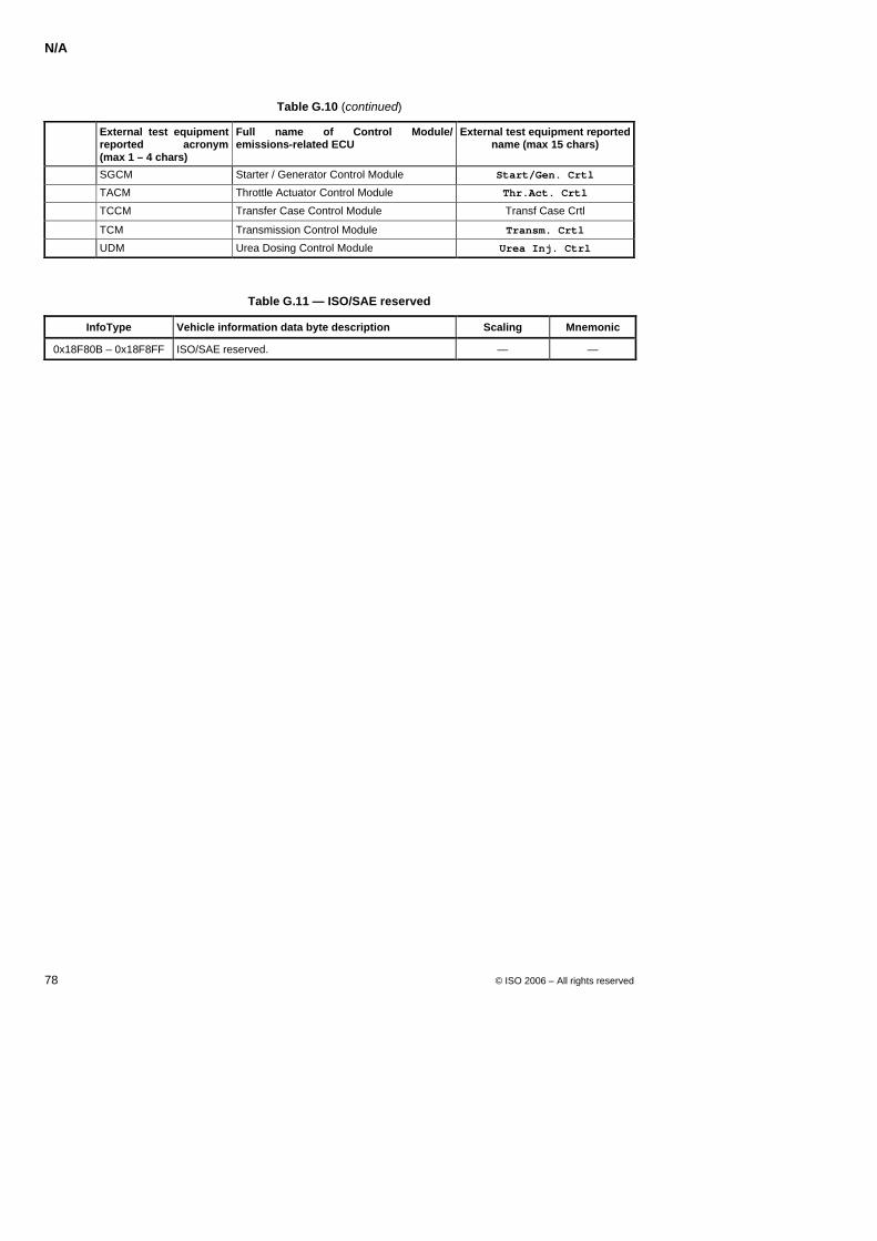
N/A
78 © ISO 2006 – All rights reserved
Table G.10 (continued)
External test equipment reported acronym (max 1 – 4 chars)
Full name of Control Module/ emissions-related ECU
External test equipment reported name (max 15 chars)
SGCM Starter / Generator Control Module Start/Gen. Crtl
TACM Throttle Actuator Control Module Thr.Act. Crtl
TCCM Transfer Case Control Module Transf Case Crtl
TCM Transmission Control Module Transm. Crtl
UDM Urea Dosing Control Module Urea Inj. Ctrl
Table G.11 — ISO/SAE reserved
InfoType Vehicle information data byte description Scaling Mnemonic
0x18F80B – 0x18F8FF ISO/SAE reserved. — —
N/A
© ISO 2006 – All rights reserved 79
Annex H (normative)
Emissions-related DTCExtendedData record definition
A value of 0x90 - 0xEF requests the server to report legislated OBD stored DTCExtendedData records.
DTC Occurrence Counter
Mise en forme : Puces etnuméros
Mis en forme : Police :NonGras
Mis en forme : Police :10 pt
N/A
80 © ISO 2006 – All rights reserved
Annex I (normative)
Emissions-related Unified Parameter Identifier (UPID)
This section will be defined in a future release of the standard.
Mise en forme : Puces et numéros
Mis en forme : Anglais (Royaume-Uni)
Mis en forme : Normal, Pas de lignessolidaires

N/A
© ISO 2006 – All rights reserved 81
Annex J (normative)
Emissions-related Legacy DTC (LDTC)
Mise en forme : Puces etnuméros
Mis en forme : Anglais(Royaume-Uni)
N/A
82 © ISO 2006 – All rights reserved
Annex K (normative)
Legacy DTC Failure Type Byte (FTB)
Mise en forme : Puces et numéros
Mis en forme : Police :Non Gras
N/A
© ISO 2006 – All rights reserved 83
Annex L (normative)
Unified DTC definition (UDTC)
This section will be defined in a future release of the standard.
Mise en forme : Puces etnuméros
Mis en forme : Anglais(Royaume-Uni)
Mis en forme : Anglais(Royaume-Uni)
N/A
84 © ISO 2006 – All rights reserved
Annex M (normativ)
Unified DTC Failure Type Byte (FTB)
This section will be defined in a future release of the standard.
Mise en forme : Puces et numéros
Mis en forme : Police :Non Gras
Mis en forme : Anglais (Royaume-Uni)
Mis en forme : Anglais (Royaume-Uni)
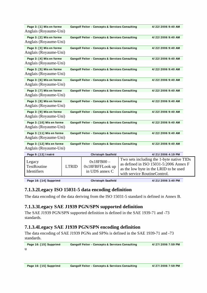
Page 3: [1] Mis en forme Gangolf Feiter - Concepts & Services Consulting 4/22/2006 9:40 AM
Anglais (Royaume-Uni)
Page 3: [2] Mis en forme Gangolf Feiter - Concepts & Services Consulting 4/22/2006 9:40 AM
Anglais (Royaume-Uni)
Page 3: [3] Mis en forme Gangolf Feiter - Concepts & Services Consulting 4/22/2006 9:40 AM
Anglais (Royaume-Uni)
Page 3: [4] Mis en forme Gangolf Feiter - Concepts & Services Consulting 4/22/2006 9:40 AM
Anglais (Royaume-Uni)
Page 3: [5] Mis en forme Gangolf Feiter - Concepts & Services Consulting 4/22/2006 9:40 AM
Anglais (Royaume-Uni)
Page 3: [6] Mis en forme Gangolf Feiter - Concepts & Services Consulting 4/22/2006 9:40 AM
Anglais (Royaume-Uni)
Page 3: [7] Mis en forme Gangolf Feiter - Concepts & Services Consulting 4/22/2006 9:40 AM
Anglais (Royaume-Uni)
Page 3: [8] Mis en forme Gangolf Feiter - Concepts & Services Consulting 4/22/2006 9:40 AM
Anglais (Royaume-Uni)
Page 3: [9] Mis en forme Gangolf Feiter - Concepts & Services Consulting 4/22/2006 9:40 AM
Anglais (Royaume-Uni)
Page 3: [10] Mis en forme Gangolf Feiter - Concepts & Services Consulting 4/22/2006 9:40 AM
Anglais (Royaume-Uni)
Page 3: [11] Mis en forme Gangolf Feiter - Concepts & Services Consulting 4/22/2006 9:40 AM
Anglais (Royaume-Uni)
Page 3: [12] Mis en forme Gangolf Feiter - Concepts & Services Consulting 4/22/2006 9:40 AM
Anglais (Royaume-Uni)
Page 9: [13] Inséré Christoph Saalfeld 4/21/2006 4:19 PM
Legacy TestRoutine Identifiers
LTRID 0x18FB00 –
0x18FBFFLook up in UDS annex C
Two sets including the 1-byte native TIDs as defined in ISO 15031-5:2006 Annex F as the low byte in the LRID to be used with service RoutineControl.
Page 16: [14] Supprimé Christoph Saalfeld 4/21/2006 3:40 PM
7.1.3.2Legacy ISO 15031-5 data encoding definition The data encoding of the data deriving from the ISO 15031-5 standard is defined in Annex B.
7.1.3.3Legacy SAE J1939 PGN/SPN supported definition The SAE J1939 PGN/SPN supported definition is defined in the SAE 1939-71 and -73 standards.
7.1.3.4Legacy SAE J1939 PGN/SPN encoding definition The data encoding of SAE J1939 PGNs and SPNs is defined in the SAE 1939-71 and -73 standards.
Page 16: [15] Supprimé Gangolf Feiter - Concepts & Services Consulting 4/27/2006 7:59 PM
u
Page 16: [15] Supprimé Gangolf Feiter - Concepts & Services Consulting 4/27/2006 7:59 PM
d
Page 16: [15] Supprimé Gangolf Feiter - Concepts & Services Consulting 4/27/2006 7:59 PM
i
Page 16: [15] Supprimé Gangolf Feiter - Concepts & Services Consulting 4/22/2006 8:18 AM
0x180000 through 0x1FFFFF
Page 16: [16] Supprimé Gangolf Feiter - Concepts & Services Consulting 4/27/2006 7:59 PM
partitioned into eight (8) pages of 64 KB segments. Page 1.8 represents the emissions-related segment while pages 1.9 - 1.15 are reserved for future definition. Each page will be lined-up with a module defined in the WWH-OBD GTR. Module B of the WWH-OBD GTR specifies the emissions-related requirements including the data to be supported which is associated with page 1.8.
Page 16: [17] Inséré Christoph Saalfeld 4/21/2006 3:43 PM
which is associated with page 1.8
Page 16: [18] Mis en forme Gangolf Feiter - Concepts & Services Consulting 4/22/2006 9:40 AM
Anglais (Royaume-Uni)
Page 16: [19] Mis en forme Gangolf Feiter - Concepts & Services Consulting 4/22/2006 9:40 AM
Anglais (Royaume-Uni)
Page 16: [20] Supprimé Gangolf Feiter - Concepts & Services Consulting 4/22/2006 9:05 AM
Table 6defines the emissions-related Unified Data Identifier page 1.8. Emissions-related data parameters are comprised of the following data identifier categories: Table 6
Page 16: [21] Supprimé Christoph Saalfeld 4/21/2006 3:46 PM
explores
Page 16: [21] Supprimé Christoph Saalfeld 4/21/2006 3:50 PM
emissions-related
Page 16: [21] Supprimé Christoph Saalfeld 4/21/2006 3:50 PM
1.8
Page 16: [21] Supprimé Christoph Saalfeld 4/21/2006 3:51 PM
Emissions-related data parameters are
Page 16: [21] Supprimé Christoph Saalfeld 4/21/2006 3:46 PM
comprized
Page 16: [22] Mis en forme Gangolf Feiter - Concepts & Services Consulting 4/22/2006 9:40 AM
Anglais (Royaume-Uni)
Page 16: [23] Mis en forme Gangolf Feiter - Concepts & Services Consulting 4/22/2006 9:40 AM
Anglais (Royaume-Uni)
Page 16: [24] Mis en forme Gangolf Feiter - Concepts & Services Consulting 4/22/2006 9:40 AM
Non Surlignage
Page 16: [25] Modifier Gangolf Feiter - Concepts & Services Consulting 4/21/2006 7:35 PM
Puces et numéros mis en forme
Page 16: [26] Mis en forme Gangolf Feiter - Concepts & Services Consulting 4/22/2006 9:40 AM
Non Surlignage
Page 16: [27] Commentaire Christoph Saalfeld 4/21/2006 4:44 PM
Also includes what was formerly known as TestID
Page 16: [28] Supprimé Gangolf Feiter - Concepts & Services Consulting 4/22/2006 9:05 AM
? Unified Test Identifier??? Unified Input-Output Control Identifier
Page 16: [29] Mis en forme Gangolf Feiter - Concepts & Services Consulting 4/22/2006 9:40 AM
Anglais (Royaume-Uni)
Page 16: [30] Mis en forme Gangolf Feiter - Concepts & Services Consulting 4/22/2006 9:40 AM
Non Surlignage
Page 16: [31] Inséré Christoph Saalfeld 4/21/2006 4:10 PM
Unified Input-Output Control Identifier
Page 16: [32] Supprimé Gangolf Feiter - Concepts & Services Consulting 4/19/2006 4:24 PM
? Unified InfoType Identifier
Page 16: [33] Mis en forme Gangolf Feiter - Concepts & Services Consulting 4/22/2006 9:40 AM
Anglais (Royaume-Uni)
Page 16: [34] Supprimé Gangolf Feiter - Concepts & Services Consulting 4/28/2006 11:30 AM
of 20 KB is reserved
Page 16: [34] Supprimé Gangolf Feiter - Concepts & Services Consulting 4/22/2006 9:06 AM
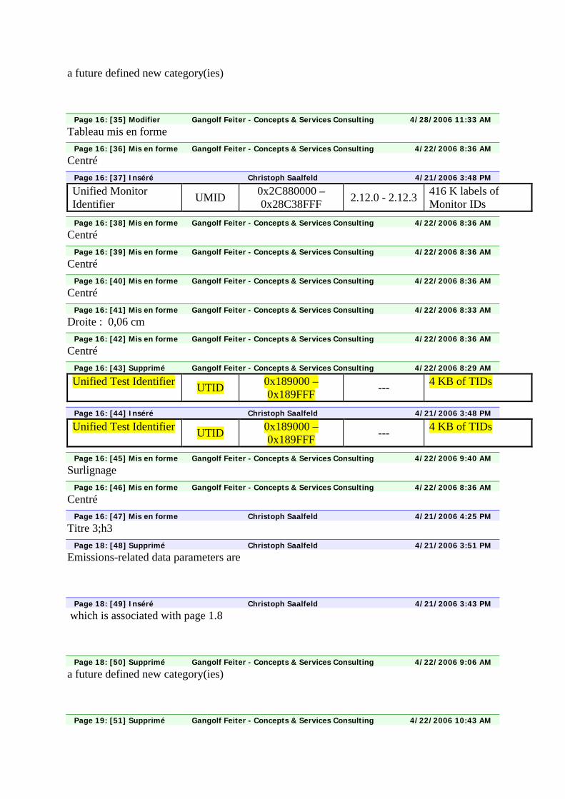
a future defined new category(ies)
Page 16: [35] Modifier Gangolf Feiter - Concepts & Services Consulting 4/28/2006 11:33 AM
Tableau mis en forme
Page 16: [36] Mis en forme Gangolf Feiter - Concepts & Services Consulting 4/22/2006 8:36 AM
Centré
Page 16: [37] Inséré Christoph Saalfeld 4/21/2006 3:48 PM
Unified Monitor Identifier UMID 0x2C880000 –
0x28C38FFF 2.12.0 - 2.12.3 416 K labels of Monitor IDs
Page 16: [38] Mis en forme Gangolf Feiter - Concepts & Services Consulting 4/22/2006 8:36 AM
Centré
Page 16: [39] Mis en forme Gangolf Feiter - Concepts & Services Consulting 4/22/2006 8:36 AM
Centré
Page 16: [40] Mis en forme Gangolf Feiter - Concepts & Services Consulting 4/22/2006 8:36 AM
Centré
Page 16: [41] Mis en forme Gangolf Feiter - Concepts & Services Consulting 4/22/2006 8:33 AM
Droite : 0,06 cm
Page 16: [42] Mis en forme Gangolf Feiter - Concepts & Services Consulting 4/22/2006 8:36 AM
Centré
Page 16: [43] Supprimé Gangolf Feiter - Concepts & Services Consulting 4/22/2006 8:29 AM
Unified Test Identifier UTID 0x189000 – 0x189FFF --- 4 KB of TIDs
Page 16: [44] Inséré Christoph Saalfeld 4/21/2006 3:48 PM
Unified Test Identifier UTID 0x189000 – 0x189FFF --- 4 KB of TIDs
Page 16: [45] Mis en forme Gangolf Feiter - Concepts & Services Consulting 4/22/2006 9:40 AM
Surlignage
Page 16: [46] Mis en forme Gangolf Feiter - Concepts & Services Consulting 4/22/2006 8:36 AM
Centré
Page 16: [47] Mis en forme Christoph Saalfeld 4/21/2006 4:25 PM
Titre 3;h3
Page 18: [48] Supprimé Christoph Saalfeld 4/21/2006 3:51 PM
Emissions-related data parameters are
Page 18: [49] Inséré Christoph Saalfeld 4/21/2006 3:43 PM
which is associated with page 1.8
Page 18: [50] Supprimé Gangolf Feiter - Concepts & Services Consulting 4/22/2006 9:06 AM
a future defined new category(ies)
Page 19: [51] Supprimé Gangolf Feiter - Concepts & Services Consulting 4/22/2006 10:43 AM
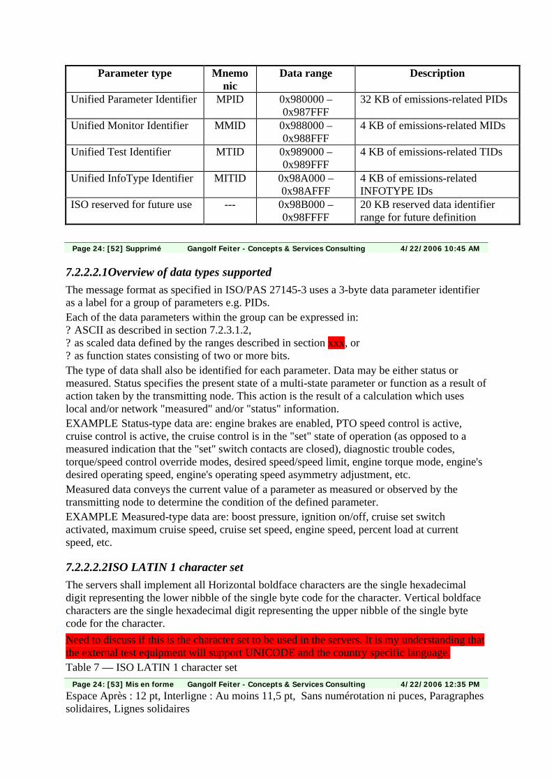
Parameter type Mnemonic
Data range Description
Unified Parameter Identifier MPID 0x980000 – 0x987FFF
32 KB of emissions-related PIDs
Unified Monitor Identifier MMID 0x988000 – 0x988FFF
4 KB of emissions-related MIDs
Unified Test Identifier MTID 0x989000 – 0x989FFF
4 KB of emissions-related TIDs
Unified InfoType Identifier MITID 0x98A000 – 0x98AFFF
4 KB of emissions-related INFOTYPE IDs
ISO reserved for future use --- 0x98B000 – 0x98FFFF
20 KB reserved data identifier range for future definition
Page 24: [52] Supprimé Gangolf Feiter - Concepts & Services Consulting 4/22/2006 10:45 AM
7.2.2.2.1Overview of data types supported The message format as specified in ISO/PAS 27145-3 uses a 3-byte data parameter identifier as a label for a group of parameters e.g. PIDs. Each of the data parameters within the group can be expressed in: ? ASCII as described in section 7.2.3.1.2, ? as scaled data defined by the ranges described in section xxx, or ? as function states consisting of two or more bits. The type of data shall also be identified for each parameter. Data may be either status or measured. Status specifies the present state of a multi-state parameter or function as a result of action taken by the transmitting node. This action is the result of a calculation which uses local and/or network "measured" and/or "status" information. EXAMPLE Status-type data are: engine brakes are enabled, PTO speed control is active, cruise control is active, the cruise control is in the "set" state of operation (as opposed to a measured indication that the "set" switch contacts are closed), diagnostic trouble codes, torque/speed control override modes, desired speed/speed limit, engine torque mode, engine's desired operating speed, engine's operating speed asymmetry adjustment, etc. Measured data conveys the current value of a parameter as measured or observed by the transmitting node to determine the condition of the defined parameter. EXAMPLE Measured-type data are: boost pressure, ignition on/off, cruise set switch activated, maximum cruise speed, cruise set speed, engine speed, percent load at current speed, etc.
7.2.2.2.2ISO LATIN 1 character set The servers shall implement all Horizontal boldface characters are the single hexadecimal digit representing the lower nibble of the single byte code for the character. Vertical boldface characters are the single hexadecimal digit representing the upper nibble of the single byte code for the character. Need to discuss if this is the character set to be used in the servers. It is my understanding that the external test equipment will support UNICODE and the country specific language. Table 7 — ISO LATIN 1 character set
Page 24: [53] Mis en forme Gangolf Feiter - Concepts & Services Consulting 4/22/2006 12:35 PM
Espace Après : 12 pt, Interligne : Au moins 11,5 pt, Sans numérotation ni puces, Paragraphes solidaires, Lignes solidaires
Page 24: [54] Supprimé Gangolf Feiter - Concepts & Services Consulting 4/22/2006 10:48 AM
7.2.2.2.3Data parameter ranges Move "signal attribute" definition from ISO27145-3 to this document and reword following section to not use data range as validity/error indicator anymore.
Page 24: [55] Supprimé Gangolf Feiter - Concepts & Services Consulting 4/22/2006 10:55 AM
XXX defines the ranges used to denote the state of a discrete parameter and Table
Page 24: [56] Inséré Christoph Saalfeld 4/21/2006 4:37 PM
Move "signal attribute" definition from ISO27145-3 to this document and reword following section to not use data range as validity/error indicator anymore.
Page 24: [57] Supprimé Gangolf Feiter - Concepts & Services Consulting 4/22/2006 10:54 AM
Table XXX defines the ranges used to determine the validity of a transmitted signal. Table
Page 24: [58] Supprimé Gangolf Feiter - Concepts & Services Consulting 4/22/2006 10:55 AM
XXX defines the ranges used to denote the state of a control mode command. The values in the range "error indicator" provide a means for a module to immediately indicate that valid parametric data is not currently available due to some type of error in the sensor, sub-system, or module. The values in the range "not available" provide a means for a module to transmit a message which contains a parameter that is not available or not supported in that module. The values in the range "not requested" provide a means for a device to transmit a command message and identify those parameters where no response is expected from the receiving device. If a component failure prevents the transmission of valid data for a parameter, the error indicator as described in Tables xxx and xxx should be used in place of that parameter’s data. However, if the measured or calculated data has yielded a value that is valid yet exceeds the defined parameter range, the error indicator should not be used. The data should be transmitted using the appropriate minimum or maximum parameter value.
Page 24: [59] Mis en forme Gangolf Feiter - Concepts & Services Consulting 4/22/2006 9:40 AM
Police :9 pt, Anglais (Royaume-Uni)
Page 24: [60] Commentaire Christoph Saalfeld 5/11/2006 3:55 PM
The whole section may be moved to ISO/PAS27145-2 as it defines the encoding of data content.
Page 27: [61] Supprimé Gangolf Feiter - Concepts & Services Consulting 4/22/2006 9:40 AM
7.2.2.2.4Assignment of new data parameters This section is intended to define a set of recommended SLOTs (Scaling, Limit, Offset, and Transfer Function) which can be used when parameters are added to J1939. This permits data consistency to be maintained as much as possible between parameters of a given type (temperature, pressure, speed, etc.). Each SLOT is intended to provide a range and resolution suitable for most parameters within a given type. When necessary, a different scaling factor or
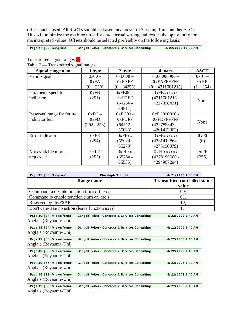
offset can be used. All SLOTs should be based on a power of 2 scaling from another SLOT. This will minimize the math required for any internal scaling and reduce the opportunity for misinterpreted values. Offsets should be selected preferably on the following basis:
Page 27: [62] Supprimé Gangolf Feiter - Concepts & Services Consulting 4/22/2006 10:50 AM
Transmitted signal ranges … Table 7 — Transmitted signal ranges
Signal range name 1 byte 2 byte 4 bytes ASCII Valid signal 0x00 –
0xFA (0 – 250)
0x0000 – 0xFAFF
(0 - 64255)
0x00000000 – 0xFAFFFFFF
(0 – 4211081215)
0x01 – 0xFE
(1 – 254) Parameter specific indicator
0xFB (251)
0xFB00 - 0xFBFF (64256 - 64511)
0xFBxxxxxx (4211081216 - 4227858431) None
Reserved range for future indicator bits
0xFC – 0xFD
(252 - 253)
0xFC00 - 0xFDFF (64512 - 65023)
0xFC000000 - 0xFDFFFFFF (4227858432 - 4261412863)
None
Error indicator 0xFE (254)
0xFExx (65024 - 65279)
0xFExxxxxx (4261412864 - 4278190079)
0x00 (0)
Not available or not requested
0xFF (255)
0xFFxx (65280 - 65535)
0xFFxxxxxx (4278190080 - 4294967294)
0xFF (255)
Page 32: [63] Supprimé Christoph Saalfeld 4/21/2006 4:56 PM
Range name Transmitted controlled status value
Command to disable function (turn off, etc.) 002 Command to enable function (turn on, etc.) 012 Reserved by ISO/SAE 102 Don't care/take no action (leave function as is) 112
Page 39: [64] Mis en forme Gangolf Feiter - Concepts & Services Consulting 4/22/2006 9:40 AM
Anglais (Royaume-Uni)
Page 39: [64] Mis en forme Gangolf Feiter - Concepts & Services Consulting 4/22/2006 9:40 AM
Anglais (Royaume-Uni)
Page 39: [65] Mis en forme Gangolf Feiter - Concepts & Services Consulting 4/22/2006 9:40 AM
Anglais (Royaume-Uni)
Page 39: [65] Mis en forme Gangolf Feiter - Concepts & Services Consulting 4/22/2006 9:40 AM
Anglais (Royaume-Uni)
Page 39: [65] Mis en forme Gangolf Feiter - Concepts & Services Consulting 4/22/2006 9:40 AM
Anglais (Royaume-Uni)
Page 39: [65] Mis en forme Gangolf Feiter - Concepts & Services Consulting 4/22/2006 9:40 AM
Anglais (Royaume-Uni)
Page 39: [66] Mis en forme Gangolf Feiter - Concepts & Services Consulting 4/22/2006 9:40 AM
Anglais (Royaume-Uni)
Page 39: [66] Mis en forme Gangolf Feiter - Concepts & Services Consulting 4/22/2006 9:40 AM
Anglais (Royaume-Uni)
Page 39: [67] Mis en forme Gangolf Feiter - Concepts & Services Consulting 4/22/2006 9:40 AM
Anglais (Royaume-Uni)
Page 39: [67] Mis en forme Gangolf Feiter - Concepts & Services Consulting 4/22/2006 9:40 AM
Anglais (Royaume-Uni)
Page 39: [67] Mis en forme Gangolf Feiter - Concepts & Services Consulting 4/22/2006 9:40 AM
Anglais (Royaume-Uni)
Page 39: [68] Mis en forme Gangolf Feiter - Concepts & Services Consulting 4/22/2006 9:40 AM
Anglais (Royaume-Uni)
Page 39: [68] Mis en forme Gangolf Feiter - Concepts & Services Consulting 4/22/2006 9:40 AM
Anglais (Royaume-Uni)
Page 39: [68] Mis en forme Gangolf Feiter - Concepts & Services Consulting 4/22/2006 9:40 AM
Anglais (Royaume-Uni)
Page 39: [68] Mis en forme Gangolf Feiter - Concepts & Services Consulting 4/22/2006 9:40 AM
Anglais (Royaume-Uni)
Page 39: [69] Mis en forme Gangolf Feiter - Concepts & Services Consulting 4/22/2006 9:40 AM
Anglais (Royaume-Uni)
Page 39: [69] Mis en forme Gangolf Feiter - Concepts & Services Consulting 4/22/2006 9:40 AM
Anglais (Royaume-Uni)
Page 39: [70] Mis en forme Gangolf Feiter - Concepts & Services Consulting 4/22/2006 9:40 AM
Anglais (Royaume-Uni)
Page 39: [70] Mis en forme Gangolf Feiter - Concepts & Services Consulting 4/22/2006 9:40 AM
Anglais (Royaume-Uni)
Page 39: [70] Mis en forme Gangolf Feiter - Concepts & Services Consulting 4/22/2006 9:40 AM
Anglais (Royaume-Uni)
Page 39: [71] Mis en forme Gangolf Feiter - Concepts & Services Consulting 4/22/2006 9:40 AM
Anglais (Royaume-Uni)
Page 39: [71] Mis en forme Gangolf Feiter - Concepts & Services Consulting 4/22/2006 9:40 AM
Anglais (Royaume-Uni)
Page 39: [71] Mis en forme Gangolf Feiter - Concepts & Services Consulting 4/22/2006 9:40 AM
Anglais (Royaume-Uni)
Page 39: [71] Mis en forme Gangolf Feiter - Concepts & Services Consulting 4/22/2006 9:40 AM
Anglais (Royaume-Uni)
Page 39: [72] Mis en forme Gangolf Feiter - Concepts & Services Consulting 4/22/2006 9:40 AM
Anglais (Royaume-Uni)
Page 39: [72] Mis en forme Gangolf Feiter - Concepts & Services Consulting 4/22/2006 9:40 AM
Anglais (Royaume-Uni)
Page 39: [73] Mis en forme Gangolf Feiter - Concepts & Services Consulting 4/22/2006 9:40 AM
Anglais (Royaume-Uni)
Page 39: [73] Mis en forme Gangolf Feiter - Concepts & Services Consulting 4/22/2006 9:40 AM
Anglais (Royaume-Uni)
Page 39: [73] Mis en forme Gangolf Feiter - Concepts & Services Consulting 4/22/2006 9:40 AM
Anglais (Royaume-Uni)
Page 39: [74] Mis en forme Gangolf Feiter - Concepts & Services Consulting 4/22/2006 9:40 AM
Anglais (Royaume-Uni)
Page 39: [74] Mis en forme Gangolf Feiter - Concepts & Services Consulting 4/22/2006 9:40 AM
Anglais (Royaume-Uni)
Page 39: [74] Mis en forme Gangolf Feiter - Concepts & Services Consulting 4/22/2006 9:40 AM
Anglais (Royaume-Uni)
Page 39: [75] Mis en forme Gangolf Feiter - Concepts & Services Consulting 4/22/2006 9:40 AM
Anglais (Royaume-Uni)
Page 39: [75] Mis en forme Gangolf Feiter - Concepts & Services Consulting 4/22/2006 9:40 AM
Anglais (Royaume-Uni)
Page 39: [75] Mis en forme Gangolf Feiter - Concepts & Services Consulting 4/22/2006 9:40 AM
Anglais (Royaume-Uni)
Page 39: [75] Mis en forme Gangolf Feiter - Concepts & Services Consulting 4/22/2006 9:40 AM
Anglais (Royaume-Uni)
Page 39: [76] Mis en forme Gangolf Feiter - Concepts & Services Consulting 4/22/2006 9:40 AM
Anglais (Royaume-Uni)
Page 39: [76] Mis en forme Gangolf Feiter - Concepts & Services Consulting 4/22/2006 9:40 AM
Anglais (Royaume-Uni)
Page 39: [77] Mis en forme Gangolf Feiter - Concepts & Services Consulting 4/22/2006 9:40 AM
Anglais (Royaume-Uni)
Page 39: [77] Mis en forme Gangolf Feiter - Concepts & Services Consulting 4/22/2006 9:40 AM
Anglais (Royaume-Uni)
Page 39: [77] Mis en forme Gangolf Feiter - Concepts & Services Consulting 4/22/2006 9:40 AM
Anglais (Royaume-Uni)
Page 39: [78] Mis en forme Gangolf Feiter - Concepts & Services Consulting 4/22/2006 9:40 AM
Anglais (Royaume-Uni)
Page 39: [78] Mis en forme Gangolf Feiter - Concepts & Services Consulting 4/22/2006 9:40 AM
Anglais (Royaume-Uni)
Page 39: [78] Mis en forme Gangolf Feiter - Concepts & Services Consulting 4/22/2006 9:40 AM
Anglais (Royaume-Uni)
Page 39: [79] Mis en forme Gangolf Feiter - Concepts & Services Consulting 4/22/2006 9:40 AM
Anglais (Royaume-Uni)
Page 39: [79] Mis en forme Gangolf Feiter - Concepts & Services Consulting 4/22/2006 9:40 AM
Anglais (Royaume-Uni)
Page 39: [79] Mis en forme Gangolf Feiter - Concepts & Services Consulting 4/22/2006 9:40 AM
Anglais (Royaume-Uni)
Page 39: [80] Mis en forme Gangolf Feiter - Concepts & Services Consulting 4/22/2006 9:40 AM
Anglais (Royaume-Uni)
Page 39: [81] Mis en forme Gangolf Feiter - Concepts & Services Consulting 4/22/2006 9:40 AM
Anglais (Royaume-Uni)
Page 39: [81] Mis en forme Gangolf Feiter - Concepts & Services Consulting 4/22/2006 9:40 AM
Anglais (Royaume-Uni)
Page 39: [81] Mis en forme Gangolf Feiter - Concepts & Services Consulting 4/22/2006 9:40 AM
Anglais (Royaume-Uni)
Page 39: [82] Mis en forme Gangolf Feiter - Concepts & Services Consulting 4/22/2006 9:40 AM
Anglais (Royaume-Uni)
Page 39: [82] Mis en forme Gangolf Feiter - Concepts & Services Consulting 4/22/2006 9:40 AM
Anglais (Royaume-Uni)
Page 39: [82] Mis en forme Gangolf Feiter - Concepts & Services Consulting 4/22/2006 9:40 AM
Anglais (Royaume-Uni)
Page 39: [83] Mis en forme Gangolf Feiter - Concepts & Services Consulting 4/22/2006 9:40 AM
Anglais (Royaume-Uni)
Page 39: [83] Mis en forme Gangolf Feiter - Concepts & Services Consulting 4/22/2006 9:40 AM
Anglais (Royaume-Uni)
Page 39: [84] Mis en forme Gangolf Feiter - Concepts & Services Consulting 4/22/2006 9:40 AM
Anglais (Royaume-Uni)
Page 39: [85] Mis en forme Gangolf Feiter - Concepts & Services Consulting 4/22/2006 9:40 AM
Anglais (Royaume-Uni)
Page 39: [85] Mis en forme Gangolf Feiter - Concepts & Services Consulting 4/22/2006 9:40 AM
Anglais (Royaume-Uni)
Page 39: [86] Mis en forme Gangolf Feiter - Concepts & Services Consulting 4/22/2006 9:40 AM
Anglais (Royaume-Uni)
Page 39: [87] Mis en forme Gangolf Feiter - Concepts & Services Consulting 4/22/2006 9:40 AM
Anglais (Royaume-Uni)
Page 39: [87] Mis en forme Gangolf Feiter - Concepts & Services Consulting 4/22/2006 9:40 AM
Anglais (Royaume-Uni)
Page 39: [87] Mis en forme Gangolf Feiter - Concepts & Services Consulting 4/22/2006 9:40 AM
Anglais (Royaume-Uni)
Page 39: [88] Mis en forme Gangolf Feiter - Concepts & Services Consulting 4/22/2006 9:40 AM
Anglais (Royaume-Uni)
Page 39: [88] Mis en forme Gangolf Feiter - Concepts & Services Consulting 4/22/2006 9:40 AM
Anglais (Royaume-Uni)
Page 39: [89] Mis en forme Gangolf Feiter - Concepts & Services Consulting 4/22/2006 9:40 AM
Anglais (Royaume-Uni)
© ISO 2006 – All rights reserved
Document type: Publicly Available Specification Document subtype: Document stage: (30) Committee Document language: E C:\WWH-obd\GENEVA 2006_06\prepa meeting\ISO_PAS_27145-3.2_(E)_WWH-OBD_CMD_2006-05-29.doc STD Version 2.1c2
ISO TC 22/SC 3 N Date: 2006-05-29
N/A
ISO TC 22/SC 3/WG 1
Secretariat: DIN
Road vehicles — Implementation of emissions-related WWH-OBD communication requirements — Part 3: Common message dictionary
Élément introductif — Élément central — Partie 3: Titre de la partie
Warning
This document is not an ISO International Standard. It is distributed for review and comment. It is subject to change without notice and may not be referred to as an International Standard.
Recipients of this draft are invited to submit, with their comments, notification of any relevant patent rights of which they are aware and to provide supporting documentation.

N/A
ii © ISO 2006 – All rights reserved
Copyright notice
This ISO document is a working draft or committee draft and is copyright-protected by ISO. While the reproduction of working drafts or committee drafts in any form for use by participants in the ISO standards development process is permitted without prior permission from ISO, neither this document nor any extract from it may be reproduced, stored or transmitted in any form for any other purpose without prior written permission from ISO.
Requests for permission to reproduce this document for the purpose of selling it should be addressed as shown below or to ISO's member body in the country of the requester:
[Indicate the full address, telephone number, fax number, telex number, and electronic mail address, as appropriate, of the Copyright Manger of the ISO member body responsible for the secretariat of the TC or SC within the framework of which the working document has been prepared.]
Reproduction for sales purposes may be subject to royalty payments or a licensing agreement.
Violators may be prosecuted.
N/A
© ISO 2006 – All rights reserved iii
Contents Page
Foreword ............................................................................................................................................................ iv Introduction.........................................................................................................................................................v 1 Scope ......................................................................................................................................................1 2 Normative references............................................................................................................................2 3 Terms and definitions ...........................................................................................................................2 4 Symbols and abbreviated terms ..........................................................................................................3 5 Conventions...........................................................................................................................................4 6 General requirements ...........................................................................................................................4 6.1 Overview of unified diagnostic services.............................................................................................4 6.2 Message byte order...............................................................................................................................4 7 Emissions-related diagnostic services implementation ...................................................................5 7.1 ReadProtocolIdentification (12 hex) service.......................................................................................5 7.1.1 Service description ...............................................................................................................................5 7.1.2 Request message..................................................................................................................................5 7.1.3 Positive response message .................................................................................................................6 7.1.4 Supported negative response codes (NRC_) .....................................................................................6 7.1.5 Message flow example ReadProtocolIdentification...........................................................................7 7.2 ClearDiagnosticInformation (14 hex) service .....................................................................................8 7.2.1 Service description ...............................................................................................................................8 7.2.2 Request message..................................................................................................................................9 7.2.3 Positive response message ...............................................................................................................10 7.2.4 Supported negative response codes (NRC_) ...................................................................................11 7.2.5 Message flow examples of ClearDiagnosticInformation.................................................................11 7.3 ReadDTCInformation (19 hex) service ..............................................................................................14 7.3.1 Service description .............................................................................................................................14 7.3.2 Request message definition...............................................................................................................15 7.3.3 Positive response message ...............................................................................................................18 7.3.4 Supported negative response codes (NRC_) ...................................................................................23 7.3.5 Message flow examples – ReadDTCInformation .............................................................................23 7.4 ReadDataByDataIdentifier (0x22) service .........................................................................................30 7.4.1 Service requirements ..........................................................................................................................30 7.4.2 Supported negative response codes (NRC_) ...................................................................................33 7.4.3 Message flow example ReadDataByDataIdentifier ..........................................................................34 7.5 RoutineControl (0x31) service ...........................................................................................................39 7.5.1 Request message................................................................................................................................39 7.5.2 Positive response message ...............................................................................................................40 7.5.3 Supported negative response codes (NRC_) ...................................................................................41 7.5.4 Message flow example(s) RoutineControl ........................................................................................42 Annex A (normative) DTC attribute definition................................................................................................43 A.1 Functional Group Identifier definition ...............................................................................................43 A.2 DTC severity and class definition......................................................................................................43 A.2.1 DTC severity definition .......................................................................................................................43 A.2.2 DTC severity bit definition..................................................................................................................44 A.2.3 DTC class definition ............................................................................................................................44 A.3 DTC status bit definition .....................................................................................................................45
N/A
iv © ISO 2006 – All rights reserved
Foreword
ISO (the International Organization for Standardization) is a worldwide federation of national standards bodies (ISO member bodies). The work of preparing International Standards is normally carried out through ISO technical committees. Each member body interested in a subject for which a technical committee has been established has the right to be represented on that committee. International organizations, governmental and non-governmental, in liaison with ISO, also take part in the work. ISO collaborates closely with the International Electrotechnical Commission (IEC) on all matters of electrotechnical standardization.
International Standards are drafted in accordance with the rules given in the ISO/IEC Directives, Part 2.
The main task of technical committees is to prepare International Standards. Draft International Standards adopted by the technical committees are circulated to the member bodies for voting. Publication as an International Standard requires approval by at least 75 % of the member bodies casting a vote.
In other circumstances, particularly when there is an urgent market requirement for such documents, a technical committee may decide to publish other types of normative document:
— an ISO Publicly Available Specification (ISO/PAS) represents an agreement between technical experts in an ISO working group and is accepted for publication if it is approved by more than 50 % of the members of the parent committee casting a vote;
— an ISO Technical Specification (ISO/TS) represents an agreement between the members of a technical committee and is accepted for publication if it is approved by 2/3 of the members of the committee casting a vote.
An ISO/PAS or ISO/TS is reviewed after three years in order to decide whether it will be confirmed for a further three years, revised to become an International Standard, or withdrawn. If the ISO/PAS or ISO/TS is confirmed, it is reviewed again after a further three years, at which time it must either be transformed into an International Standard or be withdrawn.
Attention is drawn to the possibility that some of the elements of this document may be the subject of patent rights. ISO shall not be held responsible for identifying any or all such patent rights.
ISO/PAS 27145-3 was prepared by Technical Committee ISO/TC 22, Road vehicles, Subcommittee SC 3, Electrical and electronic equipment.
ISO/PAS 27145 consists of the following parts, under the general title Road vehicles — Implementation of emissions-related WWH-OBD communication requirements:
Part 1: General information and use cases definition
Part 2: Common emissions-related data dictionary
Part 3: Common message dictionary
Part 4: Connection between vehicle and test equipment
Part 5: External test equipment
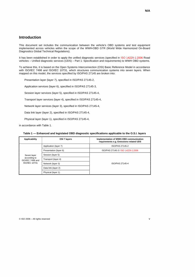
N/A
© ISO 2006 – All rights reserved v
Introduction
This document set includes the communication between the vehicle's OBD systems and test equipment implemented across vehicles within the scope of the WWH-OBD GTR (World Wide Harmonized On-Board Diagnostics Global Technical Regulations).
It has been established in order to apply the unified diagnostic services (specified in ISO 14229-1:2006 Road vehicles – Unified diagnostic services (UDS) – Part 1: Specification and requirements) to WWH OBD systems.
To achieve this, it is based on the Open Systems Interconnection (OSI) Basic Reference Model in accordance with ISO/IEC 7498 and ISO/IEC 10731, which structures communication systems into seven layers. When mapped on this model, the services specified by ISO/PAS 27145 are broken into:
Presentation layer (layer 7), specified in ISO/PAS 27145-2,
Application services (layer 6), specified in ISO/PAS 27145-3,
Session layer services (layer 5), specified in ISO/PAS 27145-4,
Transport layer services (layer 4), specified in ISO/PAS 27145-4,
Network layer services (layer 3), specified in ISO/PAS 27145-4,
Data link layer (layer 2), specified in ISO/PAS 27145-4,
Physical layer (layer 1), specified in ISO/PAS 27145-4,
in accordance with Table 1.
Table 1 — Enhanced and legislated OBD diagnostic specifications applicable to the O.S.I. layers
Applicability OSI 7 layers Implementation of WWH-OBD communication requirements e.g. Emissions-related UDS
Application (layer 7) ISO/PAS 27145-2
Presentation (layer 6) ISO/PAS 27145-3 / ISO 14229-1:2006
Session (layer 5)
Transport (layer 4)
Network (layer 3)
Data link (layer 2)
Seven layer according to
ISO/IEC 7498 and ISO/IEC 10731
Physical (layer 1)
ISO/PAS 27145-4

N/A
© ISO 2006 – All rights reserved 1
Road vehicles — Implementation of emissions-related WWH-OBD communication requirements — Part 3: Common message dictionary
1 Scope
Part 3: Common message dictionary definition of ISO/PAS 27145 specifies the implementation of a subset of unified diagnostic services (UDS) as specified in ISO 14229-1:2006. The diagnostic services are used to communicate all diagnostic data as defined in ISO/PAS 27145-2 Common emissions-related data dictionary and future specifications as part of this standard between the vehicle under test and the external test equipment.
The subset of unified diagnostic services derives from the requirements stated in the WWH-OBD GTR (World Wide Harmonised Global Technical Regulations). The common message set defined in this part is independent of the underlying Transport, Network, Data Link and Physical Layer. This document does not specify any requirements for the in-vehicle network architecture.
This part of the International Standard includes a superset of a modified version of ISO 14229-1:2006. Several significant modifications are included in this part in order to support the data set of SAE J1939, ISO 15031-5:2006 and ISO 15031-6:2005:
ISO/PAS 27145-3 supports a 3-byte Unified Data Identifier format in all services which support a 2-byte data identifier format in the ISO 14229-1:2006,
ISO/PAS 27145-3 supports a 4-byte Diagnostic Trouble Code format in all services which support a 3-byte Diagnostic Trouble Code format in the ISO 14229-1:2006,
ISO/PAS 27145-3 supports a separation of BaseDTC number from a FailureTypeByte including the symptom of the Diagnostic Trouble Code.
This specification is designed to provide the basis of unified diagnostic services for future GTR modules provided by legislation.
N/A
2 © ISO 2006 – All rights reserved
2 Normative references
The following referenced documents are indispensable for the application of this document. For dated references, only the edition cited applies. For undated references, the latest edition of the referenced document (including any amendments) applies.
ISO 7498-1:1984, Information processing systems — Open systems interconnection — Basic reference model
ISO/IEC 10731:1994, Information technology — Open Systems Interconnection — Basic Reference Model — Conventions for the definition of OSI services
ISO 4092:1988/, Road vehicles — Testers for motor vehicles — Vocabulary Technical Corrigendum 1 Cor.1:1991
ISO 14229-1:2006, Road vehicles — Unified diagnostic services (UDS) — Part 1: Specification and requirements
ISO 15031-5:2006, Road vehicles — Communication between vehicle and external test equipment for emissions-related diagnostics — Part 5: Emissions-related diagnostic services
ISO 15031-6:2005, Road vehicles — Communication between vehicle and external test equipment for emissions-related diagnostics — Part 6: Diagnostic trouble code definition
SAE J1939-21, Recommended Practice for a Serial Control and Communication Vehicle Network — Data link layer
SAE J1939-71, Recommended Practice for a Serial Control and Communication Vehicle Network — Vehicle application layer
SAE J1939-73, Recommended Practice for a Serial Control and Communication Vehicle Network — Application layer — Diagnostics
ISO/PAS 27145-1, Road vehicles — Implementation of WWH-OBD communication requirements — Part 1: General information and use case definition
ISO/PAS 27145-2, Road vehicles — Implementation of WWH-OBD communication requirements — Part 2: Common emissions-related data dictionary
ISO/PAS 27145-4, Road vehicles — Implementation of WWH-OBD communication requirements — Part 4: Connection between vehicle and test equipment
ISO/PAS 27145-5, Road vehicles — Implementation of WWH-OBD communication requirements — Part 5: External test equipment
3 Terms and definitions
For the purposes of this document, the terms and definitions given in ISO/PAS 27145-1 and the following applies.
3.1 3.2 term text of the definition
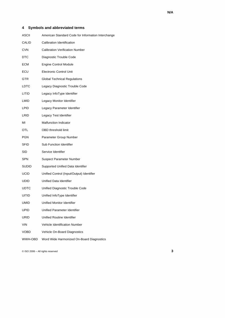
N/A
© ISO 2006 – All rights reserved 3
4 Symbols and abbreviated terms
ASCII American Standard Code for Information Interchange
CALID Calibration Identification
CVN Calibration Verification Number
DTC Diagnostic Trouble Code
ECM Engine Control Module
ECU Electronic Control Unit
GTR Global Technical Regulations
LDTC Legacy Diagnostic Trouble Code
LITID Legacy InfoType Identifier
LMID Legacy Monitor Identifier
LPID Legacy Parameter Identifier
LRID Legacy Test Identifier
MI Malfunction Indicator
OTL OBD threshold limit
PGN Parameter Group Number
SFID Sub Function Identifier
SID Service Identifier
SPN Suspect Parameter Number
SUDID Supported Unified Data Identifier
UCID Unified Control (Input/Output) Identifier
UDID Unified Data Identifier
UDTC Unified Diagnostic Trouble Code
UITID Unified InfoType Identifier
UMID Unified Monitor Identifier
UPID Unified Parameter Identifier
URID Unified Routine Identifier
VIN Vehicle Identification Number
VOBD Vehicle On-Board Diagnostics
WWH-OBD Word Wide Harmonized On-Board Diagnostics
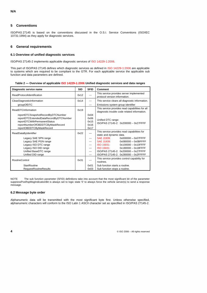
N/A
4 © ISO 2006 – All rights reserved
5 Conventions
ISO/PAS 27145 is based on the conventions discussed in the O.S.I. Service Conventions (ISO/IEC 10731:1994) as they apply for diagnostic services.
6 General requirements
6.1 Overview of unified diagnostic services
ISO/PAS 27145-2 implements applicable diagnostic services of ISO 14229-1:2006.
This part of ISO/PAS 27145 defines which diagnostic services as defined in ISO 14229-1:2006 are applicable to systems which are required to be compliant to the GTR. For each applicable service the applicable sub function and data parameters are defined.
Table 2 — Overview of applicable ISO 14229-1:2006 Unified diagnostic services and data ranges
Diagnostic service name SID SFID Comment
ReadProtocolIdentification 0x12 --- This service provides server implemented protocol version information.
ClearDiagnosticInformation 0x14 --- This service clears all diagnostic information.
groupOfDTC --- Emissions system group identifier
ReadDTCInformation 0x19 This service provides read capabilities for all diagnostic trouble code related information.
reportDTCSnapshotRecordByDTCNumber reportDTCExtendedDataRecordByDTCNumber reportDTCWithPermanentStatus reportNumberOfOBDDTCByMaskRecord reportOBDDTCByMaskRecord
0x04 0x06 0x15 0x16 0x17
Unified DTC range: ISO/PAS 27145-2: 0x200000 – 0x27FFFF
ReadDataByIdentifier 0x22 --- This service provides read capabilities for static and dynamic data.
Legacy SAE SPN range Legacy SAE PGN range Legacy ISO DTC range Legacy ISO DID range Unified BaseDTC range Unified DID range
--- --- --- --- --- ---
SAE J1939: 0x000000 – 0x07FFFF SAE J1939: 0x080000 – 0x0BFFFF ISO 15031: 0x100000 – 0x10FFFF ISO 15031: 0x180000 – 0x18FFFF ISO/PAS 27145-2: 0x200000 – 0x27FFFF ISO/PAS 27145-2: 0x280000 – 0x2FFFFF
RoutineControl 0x31 --- This service provides control capability for routines.
StartRoutine RequestRoutineResults
0x01 0x03
Sub function starts a routine. Sub function stops a routine.
NOTE The sub function parameter (SFID) definitions take into account that the most significant bit of the parameter suppressPosRspMsgIndicationBit is always set to logic state '0' to always force the vehicle server(s) to send a response message.
6.2 Message byte order
Alphanumeric data will be transmitted with the most significant byte first. Unless otherwise specified, alphanumeric characters will conform to the ISO Latin 1 ASCII character set as specified in ISO/PAS 27145-2.
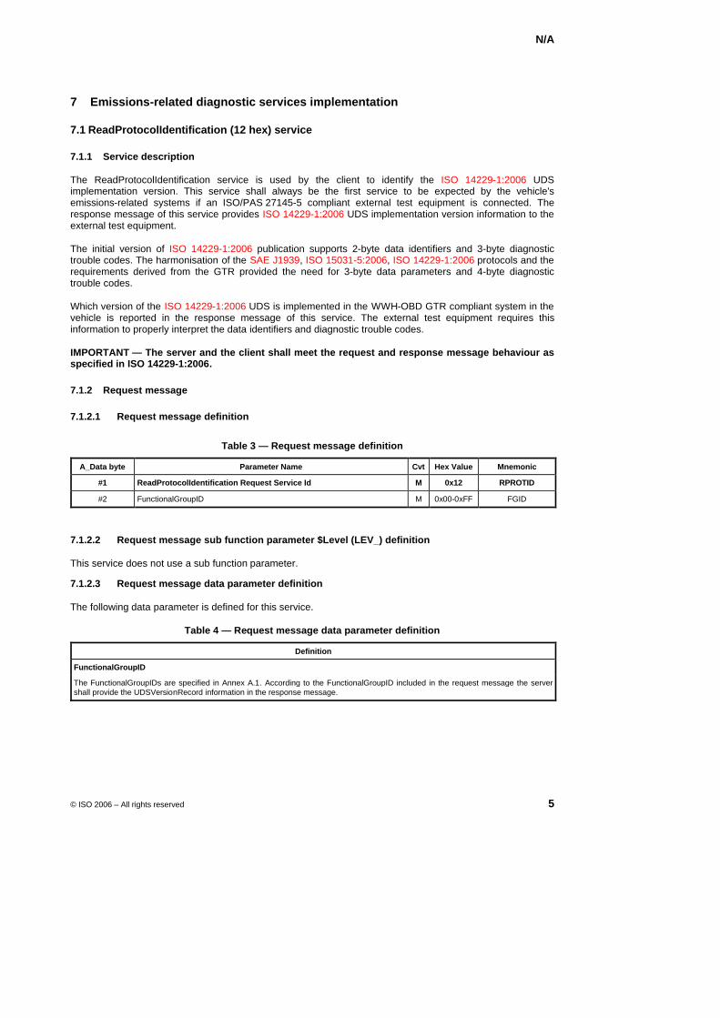
N/A
© ISO 2006 – All rights reserved 5
7 Emissions-related diagnostic services implementation
7.1 ReadProtocolIdentification (12 hex) service
7.1.1 Service description
The ReadProtocolIdentification service is used by the client to identify the ISO 14229-1:2006 UDS implementation version. This service shall always be the first service to be expected by the vehicle's emissions-related systems if an ISO/PAS 27145-5 compliant external test equipment is connected. The response message of this service provides ISO 14229-1:2006 UDS implementation version information to the external test equipment.
The initial version of ISO 14229-1:2006 publication supports 2-byte data identifiers and 3-byte diagnostic trouble codes. The harmonisation of the SAE J1939, ISO 15031-5:2006, ISO 14229-1:2006 protocols and the requirements derived from the GTR provided the need for 3-byte data parameters and 4-byte diagnostic trouble codes.
Which version of the ISO 14229-1:2006 UDS is implemented in the WWH-OBD GTR compliant system in the vehicle is reported in the response message of this service. The external test equipment requires this information to properly interpret the data identifiers and diagnostic trouble codes.
IMPORTANT — The server and the client shall meet the request and response message behaviour as specified in ISO 14229-1:2006.
7.1.2 Request message
7.1.2.1 Request message definition
Table 3 — Request message definition
A_Data byte Parameter Name Cvt Hex Value Mnemonic
#1 ReadProtocolIdentification Request Service Id M 0x12 RPROTID
#2 FunctionalGroupID M 0x00-0xFF FGID
7.1.2.2 Request message sub function parameter $Level (LEV_) definition
This service does not use a sub function parameter.
7.1.2.3 Request message data parameter definition
The following data parameter is defined for this service.
Table 4 — Request message data parameter definition
Definition
FunctionalGroupID
The FunctionalGroupIDs are specified in Annex A.1. According to the FunctionalGroupID included in the request message the server shall provide the UDSVersionRecord information in the response message.
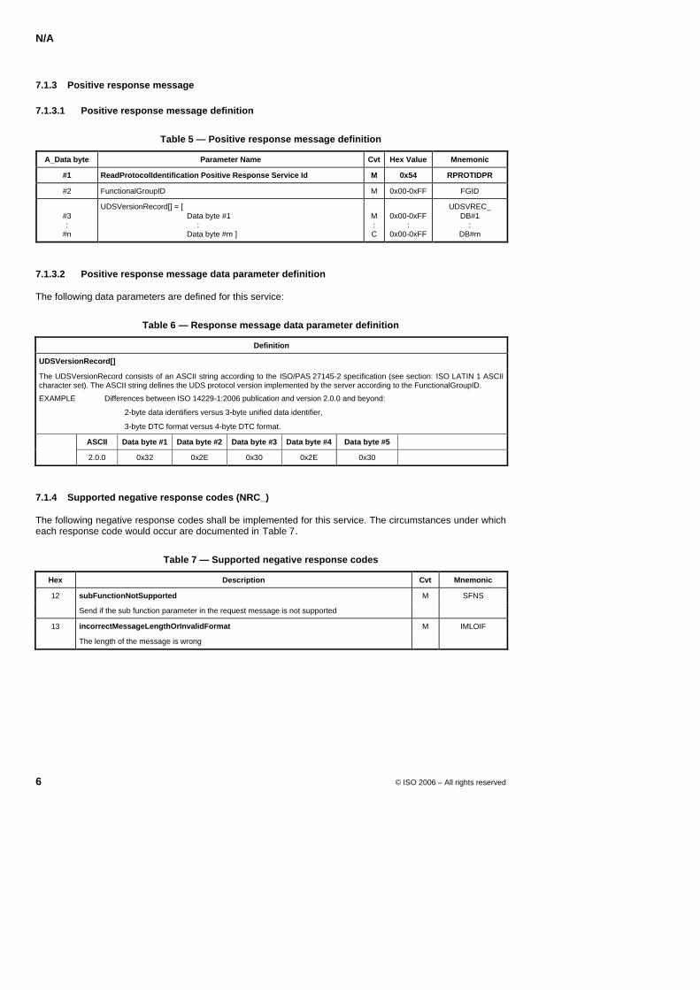
N/A
6 © ISO 2006 – All rights reserved
7.1.3 Positive response message
7.1.3.1 Positive response message definition
Table 5 — Positive response message definition
A_Data byte Parameter Name Cvt Hex Value Mnemonic
#1 ReadProtocolIdentification Positive Response Service Id M 0x54 RPROTIDPR
#2 FunctionalGroupID M 0x00-0xFF FGID
#3 :
#n
UDSVersionRecord[] = [ Data byte #1 : Data byte #m ]
M : C
0x00-0xFF
: 0x00-0xFF
UDSVREC_ DB#1
: DB#m
7.1.3.2 Positive response message data parameter definition
The following data parameters are defined for this service:
Table 6 — Response message data parameter definition
Definition
UDSVersionRecord[]
The UDSVersionRecord consists of an ASCII string according to the ISO/PAS 27145-2 specification (see section: ISO LATIN 1 ASCII character set). The ASCII string defines the UDS protocol version implemented by the server according to the FunctionalGroupID.
EXAMPLE Differences between ISO 14229-1:2006 publication and version 2.0.0 and beyond:
2-byte data identifiers versus 3-byte unified data identifier,
3-byte DTC format versus 4-byte DTC format.
ASCII Data byte #1 Data byte #2 Data byte #3 Data byte #4 Data byte #5
2.0.0 0x32 0x2E 0x30 0x2E 0x30
7.1.4 Supported negative response codes (NRC_)
The following negative response codes shall be implemented for this service. The circumstances under which each response code would occur are documented in XTable 7X.
Table 7 — Supported negative response codes
Hex Description Cvt Mnemonic
12 subFunctionNotSupported M SFNS
Send if the sub function parameter in the request message is not supported
13 incorrectMessageLengthOrInvalidFormat M IMLOIF
The length of the message is wrong
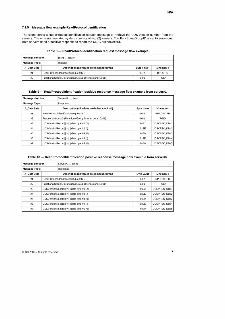
N/A
© ISO 2006 – All rights reserved 7
7.1.5 Message flow example ReadProtocolIdentification
The client sends a ReadProtocolIdentification request message to retrieve the UDS version number from the servers. The emissions-related system consists of two (2) servers. The FunctionalGroupID is set to emissions. Both servers send a positive response to report the UDSVersionRecord.
Table 8 — ReadProtocolIdentification request message flow example
Message direction: client → server
Message Type: Request
A_Data Byte Description (all values are in hexadecimal) Byte Value Mnemonic
#1 ReadProtocolIdentification request SID 0x12 RPROTID
#2 FunctionalGroupID (FunctionalGroupID=emissions=0x01) 0x01 FGID
Table 9 — ReadProtocolIdentification positive response message flow example from server#1
Message direction: Server#1 → client
Message Type: Response
A_Data Byte Description (all values are in hexadecimal) Byte Value Mnemonic
#1 ReadProtocolIdentification request SID 0x52 RPROTIDPR
#2 FunctionalGroupID (FunctionalGroupID=emissions=0x01) 0x01 FGID
#3 UDSVersionRecord[] = [ ] data byte #1 (2) 0x32 UDSVREC_DB#1
#4 UDSVersionRecord[] = [ ] data byte #2 (.) 0x2E UDSVREC_DB#2
#5 UDSVersionRecord[] = [ ] data byte #3 (0) 0x30 UDSVREC_DB#3
#6 UDSVersionRecord[] = [ ] data byte #4 (.) 0x2E UDSVREC_DB#4
#7 UDSVersionRecord[] = [ ] data byte #5 (0) 0x30 UDSVREC_DB#5
Table 10 — ReadProtocolIdentification positive response message flow example from server#2
Message direction: Server#2 → client
Message Type: Response
A_Data Byte Description (all values are in hexadecimal) Byte Value Mnemonic
#1 ReadProtocolIdentification request SID 0x52 RPROTIDPR
#2 FunctionalGroupID (FunctionalGroupID=emissions=0x01) 0x01 FGID
#3 UDSVersionRecord[] = [ ] data byte #1 (2) 0x32 UDSVREC_DB#1
#4 UDSVersionRecord[] = [ ] data byte #2 (.) 0x2E UDSVREC_DB#2
#5 UDSVersionRecord[] = [ ] data byte #3 (0) 0x30 UDSVREC_DB#3
#6 UDSVersionRecord[] = [ ] data byte #4 (.) 0x2E UDSVREC_DB#4
#7 UDSVersionRecord[] = [ ] data byte #5 (0) 0x30 UDSVREC_DB#5
N/A
8 © ISO 2006 – All rights reserved
7.2 ClearDiagnosticInformation (14 hex) service
7.2.1 Service description
The ClearDiagnosticInformation service is used by the client to clear diagnostic information in one or multiple servers’ memory.
The server shall send a positive response when the ClearDiagnosticInformation service is completely processed. The server shall send a positive response even if no DTCs are stored. The server shall support an additional copy of permanentDTC status information in memory. Individual DTCs are erased by the server DTC monitoring logic if successfully executed with a 'pass' result. The permanentDTC status information within a server's memory shall neither be possible to be cleared by an external test equipment nor by a battery disconnect. Additional copies, e.g. backup copy in long-term memory, are updated according to the appropriate backup strategy (e.g. in the power-latch phase).
NOTE In case the power-latch phase is disturbed (e.g., a battery disconnect during the power-latch phase) this may cause data inconsistency.
The request message of the client contains the parameter groupOfDTC which allows the client to clear a functional system group of DTCs (e.g., emissions), or a specific DTC.
This service provides means for the external test equipment to command servers to clear all diagnostic information related to the functional group identifier included in the request message.
For the emissions functional system group the following diagnostic information shall be cleared:
MIL and number of diagnostic trouble codes,
I/M (Inspection/Maintenance) readiness bits,
Confirmed diagnostic trouble codes,
Pending diagnostic trouble codes,
Diagnostic trouble code for snapshot record data,
Snapshot record data,
Status of system monitoring tests,
On-board monitoring test results,
Distance travelled while MIL is activated,
Number of warm-ups since DTCs cleared,
Distance travelled since DTCs cleared,
Time run by the engine while MIL is activated,
Time since diagnostic trouble codes cleared,
Reset misfire counts of standardized Test ID 0x0B to zero,
DTC status byte,
captured DTC extended data (DTCExtendedData, ReadDTCInformationX),
other DTC related data such as first/most recent DTC, flags, counters, timers, etc. specific to DTCs.
Other manufacturer specific “clearing/resetting” actions may also occur in response to this request message. If any of the above requirements is in conflict with the applicable local regulation the legislated requirements supersede.
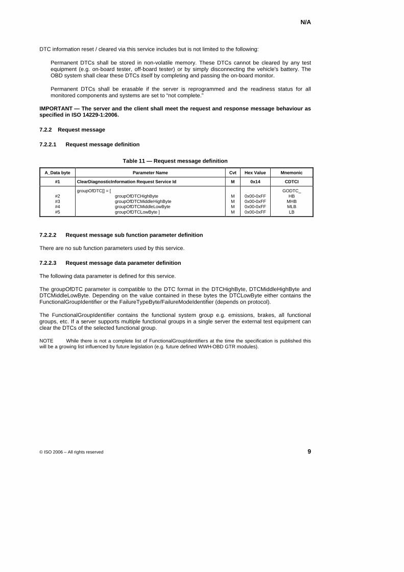
N/A
© ISO 2006 – All rights reserved 9
DTC information reset / cleared via this service includes but is not limited to the following:
Permanent DTCs shall be stored in non-volatile memory. These DTCs cannot be cleared by any test equipment (e.g. on-board tester, off-board tester) or by simply disconnecting the vehicle's battery. The OBD system shall clear these DTCs itself by completing and passing the on-board monitor.
Permanent DTCs shall be erasable if the server is reprogrammed and the readiness status for all monitored components and systems are set to “not complete.”
IMPORTANT — The server and the client shall meet the request and response message behaviour as specified in ISO 14229-1:2006.
7.2.2 Request message
7.2.2.1 Request message definition
Table 11 — Request message definition
A_Data byte Parameter Name Cvt Hex Value Mnemonic
#1 ClearDiagnosticInformation Request Service Id M 0x14 CDTCI
#2 #3 #4 #5
groupOfDTC[] = [ groupOfDTCHighByte groupOfDTCMiddleHighByte groupOfDTCMiddleLowByte groupOfDTCLowByte ]
M M M M
0x00-0xFF 0x00-0xFF 0x00-0xFF 0x00-0xFF
GODTC_ HB
MHB MLB LB
7.2.2.2 Request message sub function parameter definition
There are no sub function parameters used by this service.
7.2.2.3 Request message data parameter definition
The following data parameter is defined for this service.
The groupOfDTC parameter is compatible to the DTC format in the DTCHighByte, DTCMiddleHighByte and DTCMiddleLowByte. Depending on the value contained in these bytes the DTCLowByte either contains the FunctionalGroupIdentifier or the FailureTypeByte/FailureModeIdentifier (depends on protocol).
The FunctionalGroupIdentifier contains the functional system group e.g. emissions, brakes, all functional groups, etc. If a server supports multiple functional groups in a single server the external test equipment can clear the DTCs of the selected functional group.
NOTE While there is not a complete list of FunctionalGroupIdentifiers at the time the specification is published this will be a growing list influenced by future legislation (e.g. future defined WWH-OBD GTR modules).
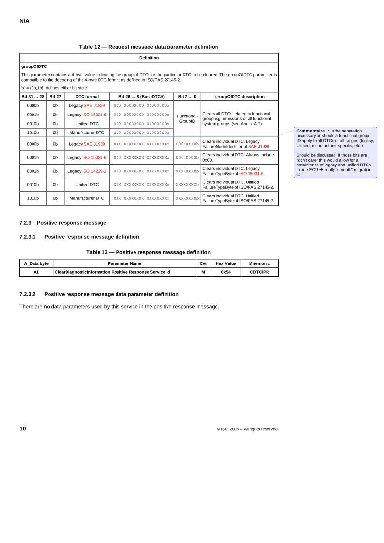
N/A
10 © ISO 2006 – All rights reserved
Table 12 — Request message data parameter definition
Definition
groupOfDTC
This parameter contains a 4-byte value indicating the group of DTCs or the particular DTC to be cleared. The groupOfDTC parameter is compatible to the decoding of the 4-byte DTC format as defined in ISO/PAS 27145-2.
'x' = 0b,1b, defines either bit state.
Bit 31 … 28 Bit 27 DTC format Bit 26 … 8 (BaseDTC#) Bit 7 … 0 groupOfDTC description
0000b 0b Legacy SAE J1939 000 00000000 00000000b
0001b 0b Legacy ISO 15031-6 000 00000000 00000000b
0010b 0b Unified DTC 000 00000000 00000000b
1010b 0b Manufacturer DTC 000 00000000 00000000b
Functional- GroupID
Clears all DTCs related to functional group e.g. emissions or all functional system groups (see Annex A.1)
0000b 0b Legacy SAE J1939 XXX XXXXXXXX XXXXXXXXb 000XXXXXb Clears individual DTC. Legacy FailureModeIdentifier of SAE J1939.
0001b 0b Legacy ISO 15031-6 000 XXXXXXXX XXXXXXXXb 00000000b Clears individual DTC. Always include 0x00.
0001b 0b Legacy ISO 14229-1 000 XXXXXXXX XXXXXXXXb XXXXXXXXb Clears individual DTC. Legacy FailureTypeByte of ISO 15031-6.
0010b 0b Unified DTC XXX XXXXXXXX XXXXXXXXb XXXXXXXXb Clears individual DTC. Unified FailureTypeByte of ISO/PAS 27145-2.
1010b 0b Manufacturer DTC XXX XXXXXXXX XXXXXXXXb XXXXXXXXb Clears individual DTC. Unified FailureTypeByte of ISO/PAS 27145-2.
7.2.3 Positive response message
7.2.3.1 Positive response message definition
Table 13 — Positive response message definition
A_Data byte Parameter Name Cvt Hex Value Mnemonic
#1 ClearDiagnosticInformation Positive Response Service Id M 0x54 CDTCIPR
7.2.3.2 Positive response message data parameter definition
There are no data parameters used by this service in the positive response message.
Commentaire : Is the separation necessary or should a functional group ID apply to all DTCs of all ranges (legacy, Unified, manufacturer specific, etc.) Should be discussed. If those bits are "don't care" this would allow for a coexistence of legacy and unified DTCs in one ECU à really "smooth" migration
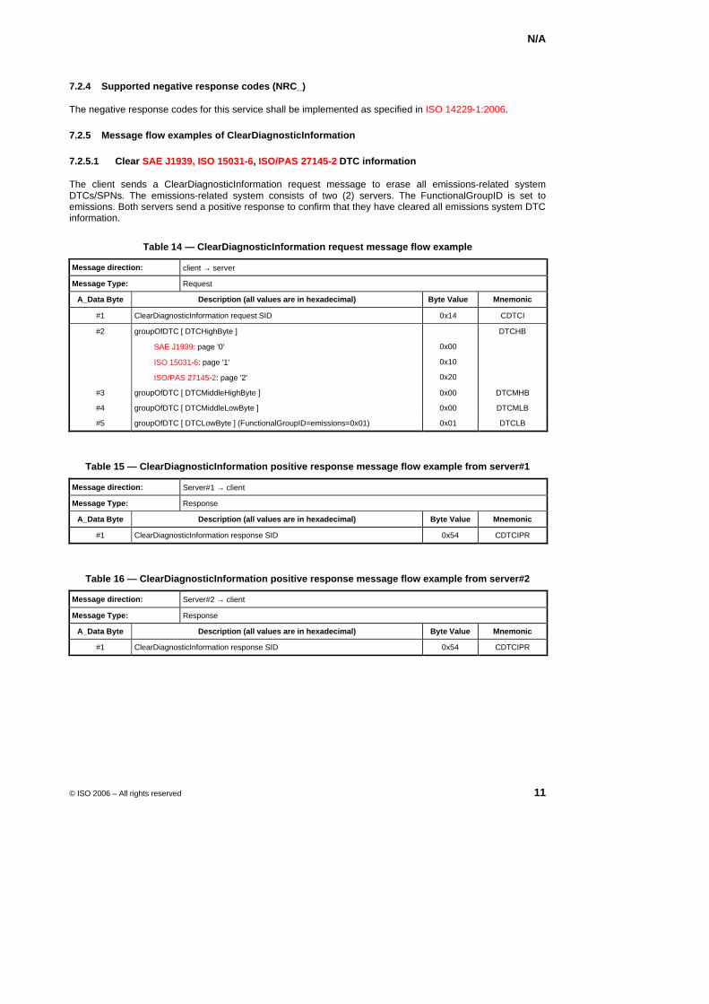
N/A
© ISO 2006 – All rights reserved 11
7.2.4 Supported negative response codes (NRC_)
The negative response codes for this service shall be implemented as specified in ISO 14229-1:2006.
7.2.5 Message flow examples of ClearDiagnosticInformation
7.2.5.1 Clear SAE J1939, ISO 15031-6, ISO/PAS 27145-2 DTC information
The client sends a ClearDiagnosticInformation request message to erase all emissions-related system DTCs/SPNs. The emissions-related system consists of two (2) servers. The FunctionalGroupID is set to emissions. Both servers send a positive response to confirm that they have cleared all emissions system DTC information.
Table 14 — ClearDiagnosticInformation request message flow example
Message direction: client → server
Message Type: Request
A_Data Byte Description (all values are in hexadecimal) Byte Value Mnemonic
#1 ClearDiagnosticInformation request SID 0x14 CDTCI
#2 groupOfDTC [ DTCHighByte ]
SAE J1939: page '0'
ISO 15031-6: page '1'
ISO/PAS 27145-2: page '2'
0x00
0x10
0x20
DTCHB
#3 groupOfDTC [ DTCMiddleHighByte ] 0x00 DTCMHB
#4 groupOfDTC [ DTCMiddleLowByte ] 0x00 DTCMLB
#5 groupOfDTC [ DTCLowByte ] (FunctionalGroupID=emissions=0x01) 0x01 DTCLB
Table 15 — ClearDiagnosticInformation positive response message flow example from server#1
Message direction: Server#1 → client
Message Type: Response
A_Data Byte Description (all values are in hexadecimal) Byte Value Mnemonic
#1 ClearDiagnosticInformation response SID 0x54 CDTCIPR
Table 16 — ClearDiagnosticInformation positive response message flow example from server#2
Message direction: Server#2 → client
Message Type: Response
A_Data Byte Description (all values are in hexadecimal) Byte Value Mnemonic
#1 ClearDiagnosticInformation response SID 0x54 CDTCIPR
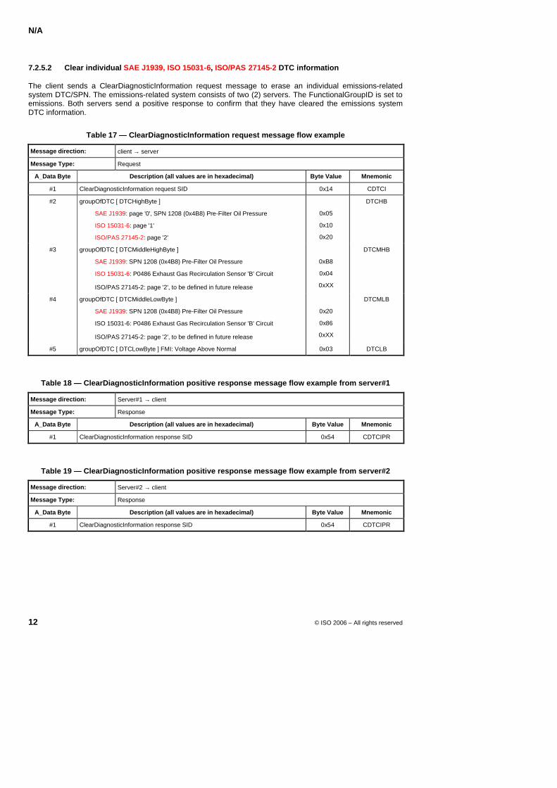
N/A
12 © ISO 2006 – All rights reserved
7.2.5.2 Clear individual SAE J1939, ISO 15031-6, ISO/PAS 27145-2 DTC information
The client sends a ClearDiagnosticInformation request message to erase an individual emissions-related system DTC/SPN. The emissions-related system consists of two (2) servers. The FunctionalGroupID is set to emissions. Both servers send a positive response to confirm that they have cleared the emissions system DTC information.
Table 17 — ClearDiagnosticInformation request message flow example
Message direction: client → server
Message Type: Request
A_Data Byte Description (all values are in hexadecimal) Byte Value Mnemonic
#1 ClearDiagnosticInformation request SID 0x14 CDTCI
#2 groupOfDTC [ DTCHighByte ]
SAE J1939: page '0', SPN 1208 (0x4B8) Pre-Filter Oil Pressure
ISO 15031-6: page '1'
ISO/PAS 27145-2: page '2'
0x05
0x10
0x20
DTCHB
#3 groupOfDTC [ DTCMiddleHighByte ]
SAE J1939: SPN 1208 (0x4B8) Pre-Filter Oil Pressure
ISO 15031-6: P0486 Exhaust Gas Recirculation Sensor 'B' Circuit
ISO/PAS 27145-2: page '2', to be defined in future release
0xB8
0x04
0xXX
DTCMHB
#4 groupOfDTC [ DTCMiddleLowByte ]
SAE J1939: SPN 1208 (0x4B8) Pre-Filter Oil Pressure
ISO 15031-6: P0486 Exhaust Gas Recirculation Sensor 'B' Circuit
ISO/PAS 27145-2: page '2', to be defined in future release
0x20
0x86
0xXX
DTCMLB
#5 groupOfDTC [ DTCLowByte ] FMI: Voltage Above Normal 0x03 DTCLB
Table 18 — ClearDiagnosticInformation positive response message flow example from server#1
Message direction: Server#1 → client
Message Type: Response
A_Data Byte Description (all values are in hexadecimal) Byte Value Mnemonic
#1 ClearDiagnosticInformation response SID 0x54 CDTCIPR
Table 19 — ClearDiagnosticInformation positive response message flow example from server#2
Message direction: Server#2 → client
Message Type: Response
A_Data Byte Description (all values are in hexadecimal) Byte Value Mnemonic
#1 ClearDiagnosticInformation response SID 0x54 CDTCIPR
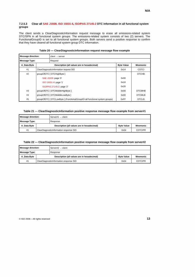
N/A
© ISO 2006 – All rights reserved 13
7.2.5.3 Clear all SAE J1939, ISO 15031-6, ISO/PAS 27145-2 DTC information in all functional system groups
The client sends a ClearDiagnosticInformation request message to erase all emissions-related system DTC/SPN in all functional system groups. The emissions-related system consists of two (2) servers. The FunctionalGroupID is set to all functional system groups. Both servers send a positive response to confirm that they have cleared all functional system group DTC information.
Table 20 — ClearDiagnosticInformation request message flow example
Message direction: client → server
Message Type: Request
A_Data Byte Description (all values are in hexadecimal) Byte Value Mnemonic
#1 ClearDiagnosticInformation request SID 0x14 CDTCI
#2 groupOfDTC [ DTCHighByte ]
SAE J1939: page '0'
ISO 15031-6: page '1'
ISO/PAS 27145-2: page '2'
0x00
0x10
0x20
DTCHB
#3 groupOfDTC [ DTCMiddleHighByte ] 0x00 DTCMHB
#4 groupOfDTC [ DTCMiddleLowByte ] 0x00 DTCMLB
#5 groupOfDTC [ DTCLowByte ] (FunctionalGroupID=all functional system groups) 0xFF DTCLB
Table 21 — ClearDiagnosticInformation positive response message flow example from server#1
Message direction: Server#1 → client
Message Type: Response
A_Data Byte Description (all values are in hexadecimal) Byte Value Mnemonic
#1 ClearDiagnosticInformation response SID 0x54 CDTCIPR
Table 22 — ClearDiagnosticInformation positive response message flow example from server#2
Message direction: Server#2 → client
Message Type: Response
A_Data Byte Description (all values are in hexadecimal) Byte Value Mnemonic
#1 ClearDiagnosticInformation response SID 0x54 CDTCIPR
N/A
14 © ISO 2006 – All rights reserved
7.3 ReadDTCInformation (19 hex) service
7.3.1 Service description
This service allows a client to read the status of server resident Diagnostic Trouble Code (DTC) information from any server, or group of servers within a vehicle.
This service allows the client to do the following:
Retrieve the number of system DTCs matching a client defined DTC status mask,
Retrieve the list of all system DTCs matching a client defined DTC status mask.
Retrieve all DTCs with "permanentDTC" status from the emissions-related system. These DTCs have been previously cleared by the ClearDiagnosticInformation service but remain in the non-volatile memory of the server until the appropriate monitors for each DTC have successfully passed,
Retrieve DTCSnapshot data associated with a client defined DTC and status mask combination: DTC Snapshots are specific data records associated with a DTC, that are stored in the server's memory. Only part of the content of the DTC Snapshots is defined in ISO/PAS 27145-2. The remaining part is based on the parameter identifier list as part of the ISO/PAS 27145-2 standard. The typical usage of DTC Snapshots is to store data upon detection of a system malfunction. The DTC Snapshots will act as a snapshot of data values from the time of the system malfunction occurrence. The data parameters stored in the DTC Snapshot shall be associated to the DTC. The DTC specific data parameters are intended to ease the fault isolation process by the technician.
Retrieve DTCExtendedData associated with a client defined DTC and status mask combination out of the DTC memory or the DTC mirror memory. DTCExtendedData consist of extended status information associated with a DTC. DTCExtendedData contains DTC parameter values, which have been identified at the time of the request. A typical use of DTCExtendedData is to store dynamic data associated with the DTC, e.g.
DTC B1 Malfunction Indicator counter which conveys the amount of time (number of engine operating hours) during which the OBD system has operated while a malfunction is active,
DTC Occurrence Counter, counts number of driving cycles in which "testFailed" has been reported,
DTC aging counter, counts number of driving cycles since the fault was latest failed excluding the driving cycles in which the test has not reported "testPassed" or "testFailed",
specific counters for OBD (e.g. number of remaining driving cycles until the "check engine" lamp is switched off if driving cycle can be performed in a fault free mode).
time of last occurrence (etc.).
test failed counter, counts number of reported "test failed" and possible other counters if the validation is performed in several steps,
uncompleted test counter, counts number of driving cycles since the test was latest completed i.e. since the test reported "testPassed" or "testFailed".

N/A
© ISO 2006 – All rights reserved 15
7.3.2 Request message definition
7.3.2.1 Request message definition
The following tables show the different structures of the ReadDTCInformation request message, based on the used sub function parameter.
Table 23 describes the request format for the reportDTCSnapshotRecordByDTCNumber sub function.
Table 23 — Request message definition - sub function = reportDTCSnapshotRecordByDTCNumber
A_Data byte Parameter Name Cvt Hex Value Mnemonic
#1 ReadDTCInformation request Service Id M 0x19 RDTCI
#2 sub function = [ reportDTCSnapshotRecordByDTCNumber ]
M 0x04
LEV_ RDTCSSBDTC
#3 #4 #5 #6
DTCMaskRecord[] = [ DTCHighByte DTCMiddleHighByte DTCMiddleLowByte DTCLowByte ]
M M M M
0x00-0xFF 0x00-0xFF 0x00-0xFF 0x00-0xFF
DTCMREC_ DTCHB
DTCMHB DTCMLB DTCLB
#7 DTCSnapshotRecordNumber M 0x00-0xFF DTCSSRN
Table 24 describes the request format for the reportDTCExtendedDataRecordByDTCNumber sub function.
Table 24 — Request message definition - sub function = reportDTCExtendedDataRecordByDTCNumber
A_Data byte Parameter Name Cvt Hex Value Mnemonic
#1 ReadDTCInformation request Service Id M 0x19 RDTCI
#2 sub function = [ reportDTCExtendedDataRecordByDTCNumber ]
M 0x06
LEV_ RDTCEDRBDN
#3 #4 #5 #6
DTCMaskRecord[] = [ DTCHighByte DTCMiddleHighByte DTCMiddleLowByte DTCLowByte ]
M M M M
0x00-0xFF 0x00-0xFF 0x00-0xFF 0x00-0xFF
DTCMREC_ DTCHB
DTCMHB DTCMLB DTCLB
#7 DTCExtendedDataRecordNumber M 0x00-0xFF DTCEDRN
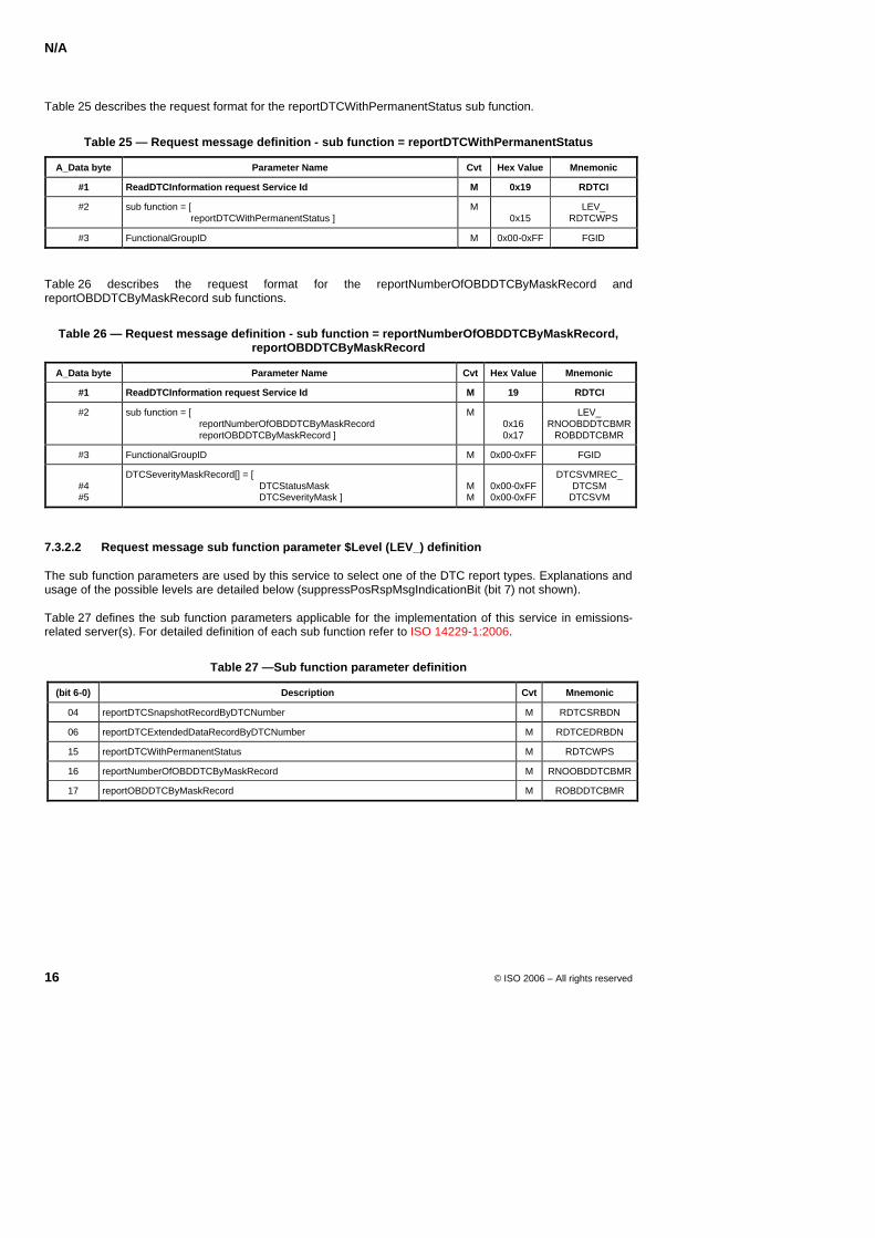
N/A
16 © ISO 2006 – All rights reserved
Table 25 describes the request format for the reportDTCWithPermanentStatus sub function.
Table 25 — Request message definition - sub function = reportDTCWithPermanentStatus
A_Data byte Parameter Name Cvt Hex Value Mnemonic
#1 ReadDTCInformation request Service Id M 0x19 RDTCI
#2 sub function = [ reportDTCWithPermanentStatus ]
M 0x15
LEV_ RDTCWPS
#3 FunctionalGroupID M 0x00-0xFF FGID
Table 26 describes the request format for the reportNumberOfOBDDTCByMaskRecord and reportOBDDTCByMaskRecord sub functions.
Table 26 — Request message definition - sub function = reportNumberOfOBDDTCByMaskRecord, reportOBDDTCByMaskRecord
A_Data byte Parameter Name Cvt Hex Value Mnemonic
#1 ReadDTCInformation request Service Id M 19 RDTCI
#2 sub function = [ reportNumberOfOBDDTCByMaskRecord reportOBDDTCByMaskRecord ]
M 0x16 0x17
LEV_ RNOOBDDTCBMR
ROBDDTCBMR
#3 FunctionalGroupID M 0x00-0xFF FGID
#4 #5
DTCSeverityMaskRecord[] = [ DTCStatusMask DTCSeverityMask ]
M M
0x00-0xFF 0x00-0xFF
DTCSVMREC_ DTCSM
DTCSVM
7.3.2.2 Request message sub function parameter $Level (LEV_) definition
The sub function parameters are used by this service to select one of the DTC report types. Explanations and usage of the possible levels are detailed below (suppressPosRspMsgIndicationBit (bit 7) not shown).
Table 27 defines the sub function parameters applicable for the implementation of this service in emissions-related server(s). For detailed definition of each sub function refer to ISO 14229-1:2006.
Table 27 —Sub function parameter definition
(bit 6-0) Description Cvt Mnemonic
04 reportDTCSnapshotRecordByDTCNumber M RDTCSRBDN
06 reportDTCExtendedDataRecordByDTCNumber M RDTCEDRBDN
15 reportDTCWithPermanentStatus M RDTCWPS
16 reportNumberOfOBDDTCByMaskRecord M RNOOBDDTCBMR
17 reportOBDDTCByMaskRecord M ROBDDTCBMR
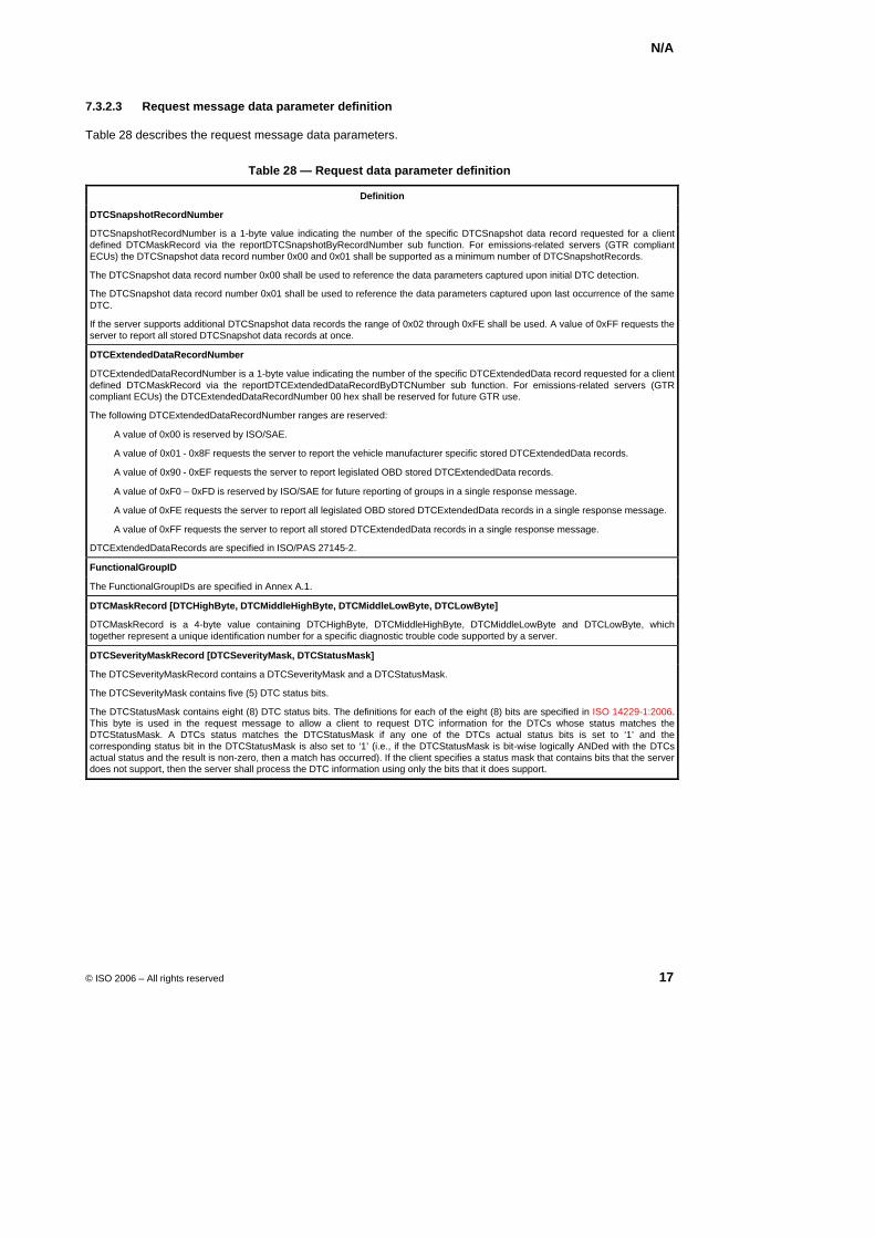
N/A
© ISO 2006 – All rights reserved 17
7.3.2.3 Request message data parameter definition
Table 28 describes the request message data parameters.
Table 28 — Request data parameter definition
Definition
DTCSnapshotRecordNumber
DTCSnapshotRecordNumber is a 1-byte value indicating the number of the specific DTCSnapshot data record requested for a client defined DTCMaskRecord via the reportDTCSnapshotByRecordNumber sub function. For emissions-related servers (GTR compliant ECUs) the DTCSnapshot data record number 0x00 and 0x01 shall be supported as a minimum number of DTCSnapshotRecords.
The DTCSnapshot data record number 0x00 shall be used to reference the data parameters captured upon initial DTC detection.
The DTCSnapshot data record number 0x01 shall be used to reference the data parameters captured upon last occurrence of the same DTC.
If the server supports additional DTCSnapshot data records the range of 0x02 through 0xFE shall be used. A value of 0xFF requests the server to report all stored DTCSnapshot data records at once.
DTCExtendedDataRecordNumber
DTCExtendedDataRecordNumber is a 1-byte value indicating the number of the specific DTCExtendedData record requested for a client defined DTCMaskRecord via the reportDTCExtendedDataRecordByDTCNumber sub function. For emissions-related servers (GTR compliant ECUs) the DTCExtendedDataRecordNumber 00 hex shall be reserved for future GTR use.
The following DTCExtendedDataRecordNumber ranges are reserved:
A value of 0x00 is reserved by ISO/SAE.
A value of 0x01 - 0x8F requests the server to report the vehicle manufacturer specific stored DTCExtendedData records.
A value of 0x90 - 0xEF requests the server to report legislated OBD stored DTCExtendedData records.
A value of 0xF0 – 0xFD is reserved by ISO/SAE for future reporting of groups in a single response message.
A value of 0xFE requests the server to report all legislated OBD stored DTCExtendedData records in a single response message.
A value of 0xFF requests the server to report all stored DTCExtendedData records in a single response message.
DTCExtendedDataRecords are specified in ISO/PAS 27145-2.
FunctionalGroupID
The FunctionalGroupIDs are specified in Annex A.1.
DTCMaskRecord [DTCHighByte, DTCMiddleHighByte, DTCMiddleLowByte, DTCLowByte]
DTCMaskRecord is a 4-byte value containing DTCHighByte, DTCMiddleHighByte, DTCMiddleLowByte and DTCLowByte, which together represent a unique identification number for a specific diagnostic trouble code supported by a server.
DTCSeverityMaskRecord [DTCSeverityMask, DTCStatusMask]
The DTCSeverityMaskRecord contains a DTCSeverityMask and a DTCStatusMask.
The DTCSeverityMask contains five (5) DTC status bits.
The DTCStatusMask contains eight (8) DTC status bits. The definitions for each of the eight (8) bits are specified in ISO 14229-1:2006. This byte is used in the request message to allow a client to request DTC information for the DTCs whose status matches the DTCStatusMask. A DTCs status matches the DTCStatusMask if any one of the DTCs actual status bits is set to ‘1’ and the corresponding status bit in the DTCStatusMask is also set to ‘1’ (i.e., if the DTCStatusMask is bit-wise logically ANDed with the DTCs actual status and the result is non-zero, then a match has occurred). If the client specifies a status mask that contains bits that the server does not support, then the server shall process the DTC information using only the bits that it does support.
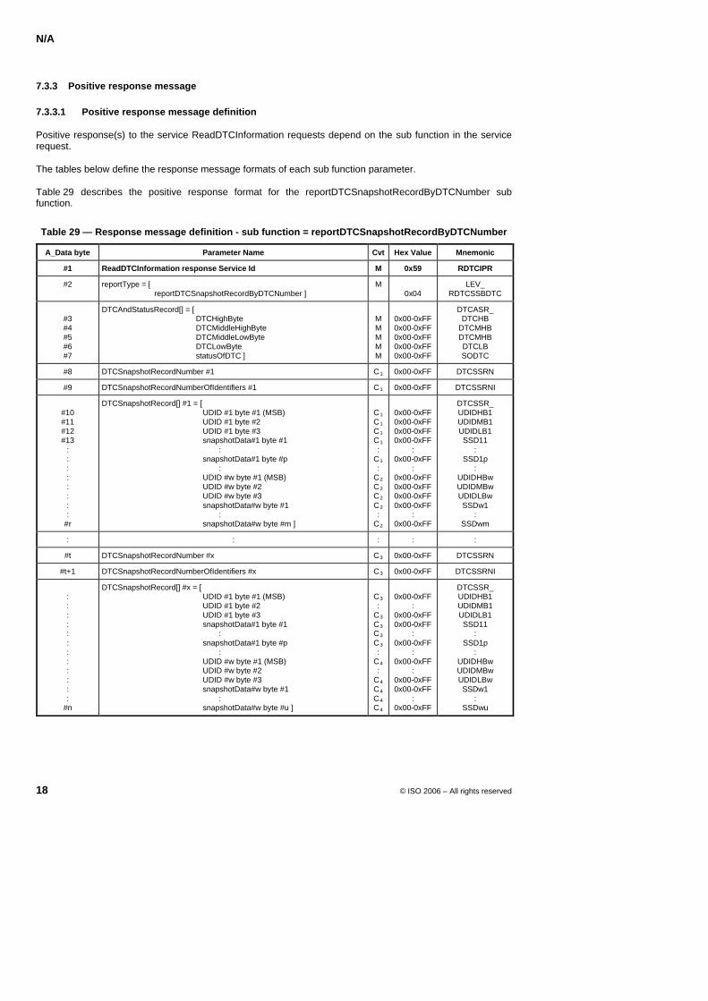
N/A
18 © ISO 2006 – All rights reserved
7.3.3 Positive response message
7.3.3.1 Positive response message definition
Positive response(s) to the service ReadDTCInformation requests depend on the sub function in the service request.
The tables below define the response message formats of each sub function parameter.
Table 29X describes the positive response format for the reportDTCSnapshotRecordByDTCNumber sub function.
Table 29 — Response message definition - sub function = reportDTCSnapshotRecordByDTCNumber
A_Data byte Parameter Name Cvt Hex Value Mnemonic
#1 ReadDTCInformation response Service Id M 0x59 RDTCIPR
#2 reportType = [ reportDTCSnapshotRecordByDTCNumber ]
M 0x04
LEV_ RDTCSSBDTC
#3 #4 #5 #6 #7
DTCAndStatusRecord[] = [ DTCHighByte DTCMiddleHighByte DTCMiddleLowByte DTCLowByte statusOfDTC ]
M M M M M
0x00-0xFF 0x00-0xFF 0x00-0xFF 0x00-0xFF 0x00-0xFF
DTCASR_ DTCHB
DTCMHB DTCMHB DTCLB SODTC
#8 DTCSnapshotRecordNumber #1 CB1B 0x00-0xFF DTCSSRN
#9 DTCSnapshotRecordNumberOfIdentifiers #1 CB1B 0x00-0xFF DTCSSRNI
#10 #11 #12 #13
: : : : : : : :
#r
DTCSnapshotRecord[] #1 = [ UDID #1 byte #1 (MSB) UDID #1 byte #2 UDID #1 byte #3 snapshotData#1 byte #1 : snapshotData#1 byte #p : UDID #w byte #1 (MSB) UDID #w byte #2 UDID #w byte #3 snapshotData#w byte #1 : snapshotData#w byte #m ]
CB1B CB1B CB1B CB1B :
CB1B :
CB2B CB2B CB2B CB2B :
CB2B
0x00-0xFF 0x00-0xFF 0x00-0xFF 0x00-0xFF
: 0x00-0xFF
: 0x00-0xFF 0x00-0xFF 0x00-0xFF 0x00-0xFF
: 0x00-0xFF
DTCSSR_ UDIDHB1 UDIDMB1 UDIDLB1 SSD11
: SSD1p
: UDIDHBw UDIDMBw UDIDLBw SSDw1
: SSDwm
: : : : :
#t DTCSnapshotRecordNumber #x CB3B 0x00-0xFF DTCSSRN
#t+1 DTCSnapshotRecordNumberOfIdentifiers #x CB3B 0x00-0xFF DTCSSRNI
: : : : : : : : : : : :
#n
DTCSnapshotRecord[] #x = [ UDID #1 byte #1 (MSB) UDID #1 byte #2 UDID #1 byte #3 snapshotData#1 byte #1 : snapshotData#1 byte #p : UDID #w byte #1 (MSB) UDID #w byte #2 UDID #w byte #3 snapshotData#w byte #1 : snapshotData#w byte #u ]
CB3B :
CB3B CB3B CB3B CB3B :
CB4B :
CB4B CB4B CB4B CB4B
0x00-0xFF
: 0x00-0xFF 0x00-0xFF
: 0x00-0xFF
: 0x00-0xFF
: 0x00-0xFF 0x00-0xFF
: 0x00-0xFF
DTCSSR_ UDIDHB1 UDIDMB1 UDIDLB1 SSD11
: SSD1p
: UDIDHBw UDIDMBw UDIDLBw SSDw1
: SSDwu
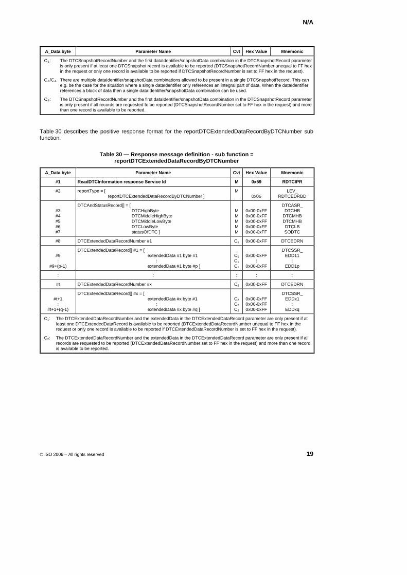
N/A
© ISO 2006 – All rights reserved 19
A_Data byte Parameter Name Cvt Hex Value Mnemonic
CB1B: The DTCSnapshotRecordNumber and the first dataIdentifier/snapshotData combination in the DTCSnapshotRecord parameter is only present if at least one DTCSnapshot record is available to be reported (DTCSnapshotRecordNumber unequal to FF hex in the request or only one record is available to be reported if DTCSnapshotRecordNumber is set to FF hex in the request).
CB2B/CB4B There are multiple dataIdentifier/snapshotData combinations allowed to be present in a single DTCSnapshotRecord. This can e.g. be the case for the situation where a single dataIdentifier only references an integral part of data. When the dataIdentifier references a block of data then a single dataIdentifier/snapshotData combination can be used.
CB3B: The DTCSnapshotRecordNumber and the first dataIdentifier/snapshotData combination in the DTCSnapshotRecord parameter is only present if all records are requested to be reported (DTCSnapshotRecordNumber set to FF hex in the request) and more than one record is available to be reported.
Table 30 describes the positive response format for the reportDTCExtendedDataRecordByDTCNumber sub function.
Table 30 — Response message definition - sub function = reportDTCExtendedDataRecordByDTCNumber
A_Data byte Parameter Name Cvt Hex Value Mnemonic
#1 ReadDTCInformation response Service Id M 0x59 RDTCIPR
#2 reportType = [ reportDTCExtendedDataRecordByDTCNumber ]
M 0x06
LEV_ RDTCEDRBD
#3 #4 #5 #6 #7
DTCAndStatusRecord[] = [ DTCHighByte DTCMiddleHighByte DTCMiddleLowByte DTCLowByte statusOfDTC ]
M M M M M
0x00-0xFF 0x00-0xFF 0x00-0xFF 0x00-0xFF 0x00-0xFF
DTCASR_ DTCHB
DTCMHB DTCMHB DTCLB SODTC
#8 DTCExtendedDataRecordNumber #1 C1 0x00-0xFF DTCEDRN
#9 :
#9+(p-1)
DTCExtendedDataRecord[] #1 = [ extendedData #1 byte #1 : extendedData #1 byte #p ]
C1 C1 C1
0x00-0xFF
: 0x00-0xFF
DTCSSR_ EDD11
: EDD1p
: : : : :
#t DTCExtendedDataRecordNumber #x C2 0x00-0xFF DTCEDRN
#t+1
: #t+1+(q-1)
DTCExtendedDataRecord[] #x = [ extendedData #x byte #1 : extendedData #x byte #q ]
C2 C2 C2
0x00-0xFF 0x00-0xFF 0x00-0xFF
DTCSSR_ EDDx1
: EDDxq
C1: The DTCExtendedDataRecordNumber and the extendedData in the DTCExtendedDataRecord parameter are only present if at least one DTCExtendedDataRecord is available to be reported (DTCExtendedDataRecordNumber unequal to FF hex in the request or only one record is available to be reported if DTCExtendedDataRecordNumber is set to FF hex in the request).
C2: The DTCExtendedDataRecordNumber and the extendedData in the DTCExtendedDataRecord parameter are only present if all records are requested to be reported (DTCExtendedDataRecordNumber set to FF hex in the request) and more than one record is available to be reported.
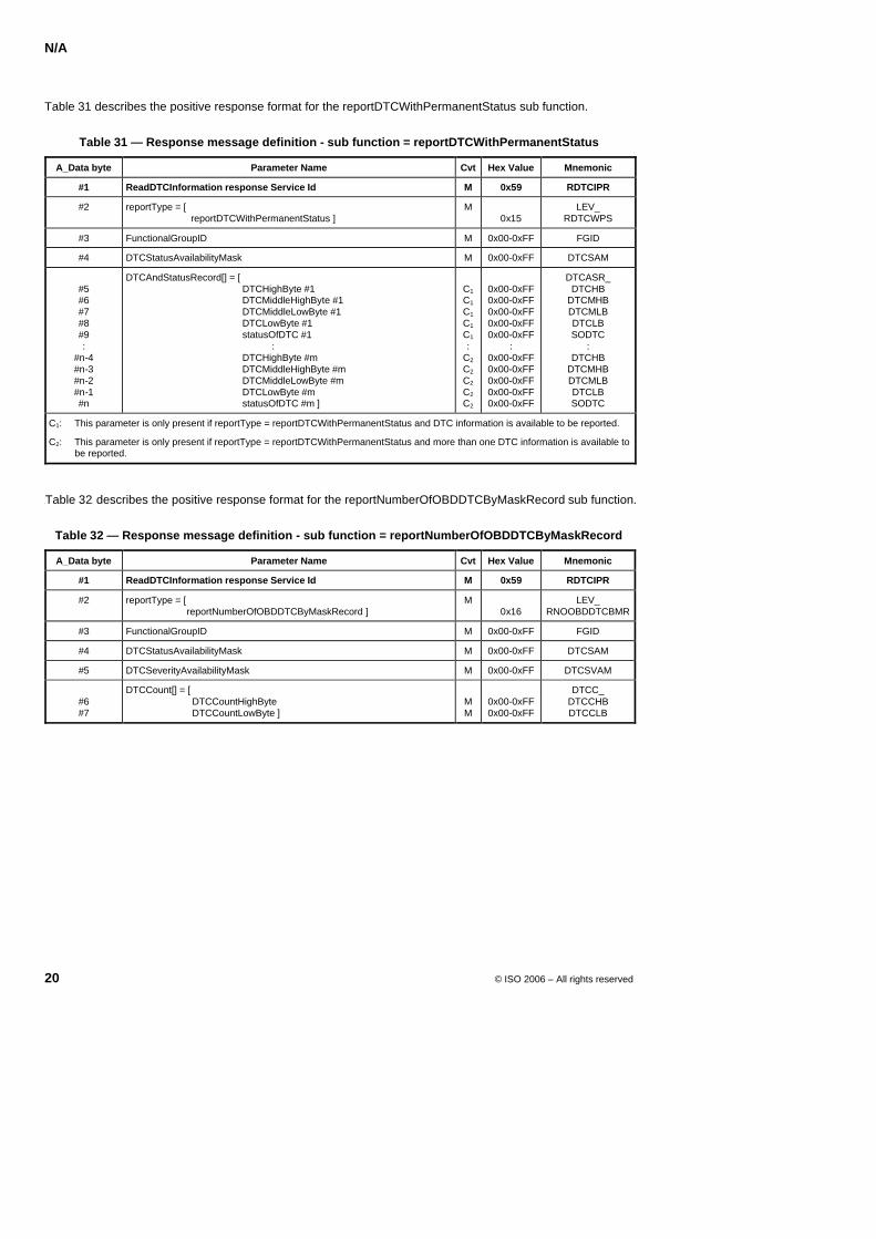
N/A
20 © ISO 2006 – All rights reserved
Table 31 describes the positive response format for the reportDTCWithPermanentStatus sub function.
Table 31 — Response message definition - sub function = reportDTCWithPermanentStatus
A_Data byte Parameter Name Cvt Hex Value Mnemonic
#1 ReadDTCInformation response Service Id M 0x59 RDTCIPR
#2 reportType = [ reportDTCWithPermanentStatus ]
M 0x15
LEV_ RDTCWPS
#3 FunctionalGroupID M 0x00-0xFF FGID
#4 DTCStatusAvailabilityMask M 0x00-0xFF DTCSAM
#5 #6 #7 #8 #9 :
#n-4 #n-3 #n-2 #n-1 #n
DTCAndStatusRecord[] = [ DTCHighByte #1 DTCMiddleHighByte #1 DTCMiddleLowByte #1 DTCLowByte #1 statusOfDTC #1 : DTCHighByte #m DTCMiddleHighByte #m DTCMiddleLowByte #m DTCLowByte #m statusOfDTC #m ]
C1 C1 C1 C1 C1
: C2 C2
C2 C2 C2
0x00-0xFF 0x00-0xFF 0x00-0xFF 0x00-0xFF 0x00-0xFF
: 0x00-0xFF 0x00-0xFF 0x00-0xFF 0x00-0xFF 0x00-0xFF
DTCASR_ DTCHB
DTCMHB DTCMLB DTCLB SODTC
: DTCHB
DTCMHB DTCMLB DTCLB SODTC
C1: This parameter is only present if reportType = reportDTCWithPermanentStatus and DTC information is available to be reported.
C2: This parameter is only present if reportType = reportDTCWithPermanentStatus and more than one DTC information is available to be reported.
XTable 32X describes the positive response format for the reportNumberOfOBDDTCByMaskRecord sub function.
Table 32 — Response message definition - sub function = reportNumberOfOBDDTCByMaskRecord
A_Data byte Parameter Name Cvt Hex Value Mnemonic
#1 ReadDTCInformation response Service Id M 0x59 RDTCIPR
#2 reportType = [ reportNumberOfOBDDTCByMaskRecord ]
M 0x16
LEV_ RNOOBDDTCBMR
#3 FunctionalGroupID M 0x00-0xFF FGID
#4 DTCStatusAvailabilityMask M 0x00-0xFF DTCSAM
#5 DTCSeverityAvailabilityMask M 0x00-0xFF DTCSVAM
#6 #7
DTCCount[] = [ DTCCountHighByte DTCCountLowByte ]
M M
0x00-0xFF 0x00-0xFF
DTCC_ DTCCHB DTCCLB
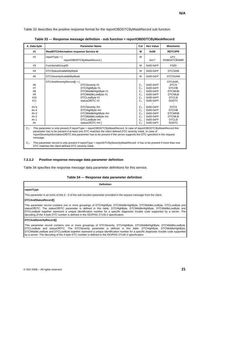
N/A
© ISO 2006 – All rights reserved 21
XTable 33X describes the positive response format for the reportOBDDTCByMaskRecord sub function.
Table 33 — Response message definition - sub function = reportOBDDTCByMaskRecord
A_Data byte Parameter Name Cvt Hex Value Mnemonic
#1 ReadDTCInformation response Service Id M 0x59 RDTCIPR
#2 reportType = [ reportOBDDTCByMaskRecord ]
M 0x17
LEV_ ROBDDTCBSMR
#3 FunctionalGroupID M 0x00-0xFF FGID
#4 DTCStatusAvailabilityMask M 0x00-0xFF DTCSAM
#5 DTCSeverityAvailabilityMask M 0x00-0xFF DTCSVAM
#6 #7 #8 #9
#10 #11
: #n-5 #n-4 #n-3 #n-2 #n-1 #n
DTCAndSeverityRecord[] = [ DTCSeverity #1 DTCHighByte #1 DTCMiddleHighByte #1 DTCMiddleLowByte #1 DTCLowByte #1 statusOfDTC #1 : DTCSeverity #m DTCHighByte #m DTCMiddleHighByte #m DTCMiddleLowByte #m DTCLowByte #m statusOfDTC #m ]
CB1B CB1B CB1B CB1B CB1B C B1
B: CB2B CB2B CB2B CB2B CB2B CB2B
0x00-0xFF 0x00-0xFF 0x00-0xFF 0x00-0xFF 0x00-0xFF 0x00-0xFF
: 0x00-0xFF 0x00-0xFF 0x00-0xFF 0x00-0xFF 0x00-0xFF 0x00-0xFF
DTCASR_ DTCS
DTCHB DTCMHB DTCMLB DTCLB SODTC
: DTCS
DTCHB DTCMHB DTCMLB DTCLB SODTC
CB1B: This parameter is only present if reportType = reportOBDDTCByMaskRecord. In case of reportOBDDTCByMaskRecord this parameter has to be present if at least one DTC matches the client defined DTC severity mask. In case of reportSeverityInformationOfDTC this parameter has to be present if the server supports the DTC specified in the request message.
CB2B: This parameter record is only present if reportType = reportDTCBySeverityMaskRecord. It has to be present if more than one DTC matches the client defined DTC severity mask.
7.3.3.2 Positive response message data parameter definition
Table 34 specifies the response message data parameter definitions for this service.
Table 34 — Response data parameter definition
Definition
reportType
This parameter is an echo of bits 6 - 0 of the sub function parameter provided in the request message from the client.
DTCAndStatusRecord[]
This parameter record contains one or more groupings of DTCHighByte, DTCMiddleHighByte, DTCMiddleLowByte, DTCLowByte and statusOfDTC. The statusOfDTC parameter is defined in this table. DTCHighByte, DTCMiddleHighByte, DTCMiddleLowByte and DTCLowByte together represent a unique identification number for a specific diagnostic trouble code supported by a server. The decoding of the 4-byte DTC number is defined in the ISO/PAS 27145-2 specification.
DTCAndSeverityRecord[]
This parameter record contains one or more groupings of DTCSeverity, DTCHighByte, DTCMiddleHighByte, DTCMiddleLowByte, DTCLowByte and statusOfDTC. The DTCSeverity parameter is defined in this table. DTCHighByte, DTCMiddleHighByte, DTCMiddleLowByte and DTCLowByte together represent a unique identification number for a specific diagnostic trouble code supported by a server. The decoding of the 4-byte DTC number is defined in the ISO/PAS 27145-2 specification.
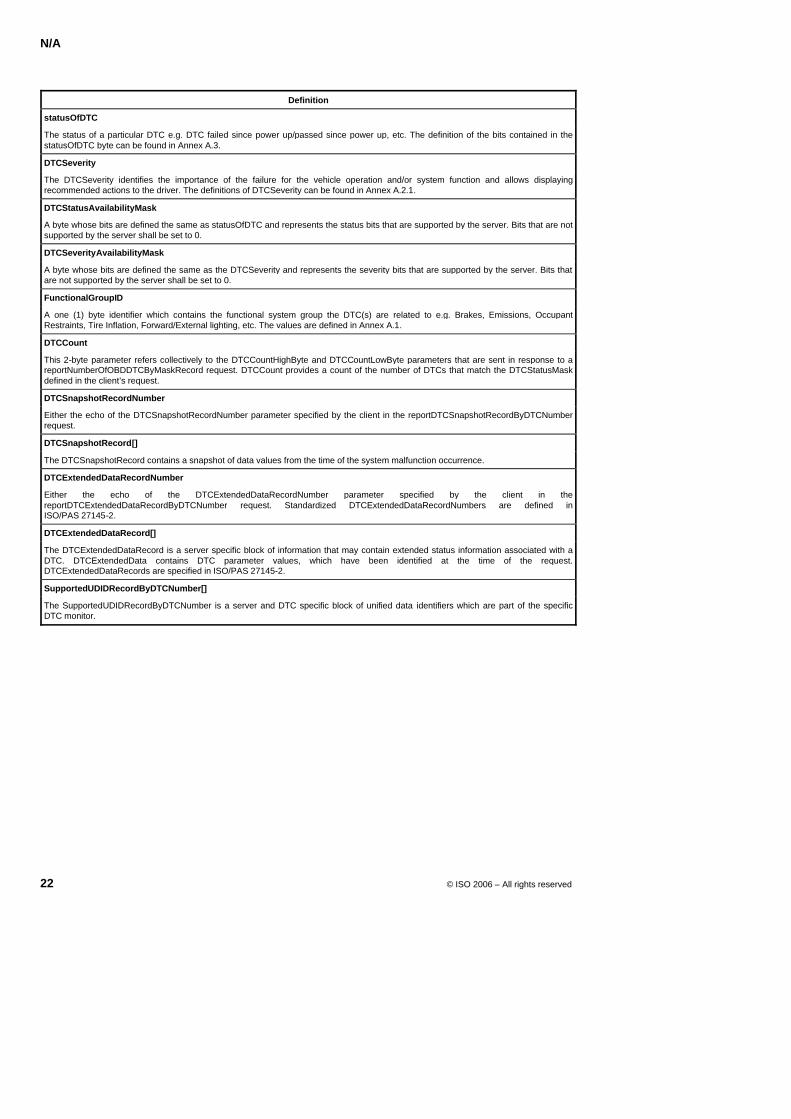
N/A
22 © ISO 2006 – All rights reserved
Definition
statusOfDTC
The status of a particular DTC e.g. DTC failed since power up/passed since power up, etc. The definition of the bits contained in the statusOfDTC byte can be found in Annex A.3.
DTCSeverity
The DTCSeverity identifies the importance of the failure for the vehicle operation and/or system function and allows displaying recommended actions to the driver. The definitions of DTCSeverity can be found in Annex A.2.1.
DTCStatusAvailabilityMask
A byte whose bits are defined the same as statusOfDTC and represents the status bits that are supported by the server. Bits that are not supported by the server shall be set to 0.
DTCSeverityAvailabilityMask
A byte whose bits are defined the same as the DTCSeverity and represents the severity bits that are supported by the server. Bits that are not supported by the server shall be set to 0.
FunctionalGroupID
A one (1) byte identifier which contains the functional system group the DTC(s) are related to e.g. Brakes, Emissions, Occupant Restraints, Tire Inflation, Forward/External lighting, etc. The values are defined in Annex A.1.
DTCCount
This 2-byte parameter refers collectively to the DTCCountHighByte and DTCCountLowByte parameters that are sent in response to a reportNumberOfOBDDTCByMaskRecord request. DTCCount provides a count of the number of DTCs that match the DTCStatusMask defined in the client’s request.
DTCSnapshotRecordNumber
Either the echo of the DTCSnapshotRecordNumber parameter specified by the client in the reportDTCSnapshotRecordByDTCNumber request.
DTCSnapshotRecord[]
The DTCSnapshotRecord contains a snapshot of data values from the time of the system malfunction occurrence.
DTCExtendedDataRecordNumber
Either the echo of the DTCExtendedDataRecordNumber parameter specified by the client in the reportDTCExtendedDataRecordByDTCNumber request. Standardized DTCExtendedDataRecordNumbers are defined in ISO/PAS 27145-2.
DTCExtendedDataRecord[]
The DTCExtendedDataRecord is a server specific block of information that may contain extended status information associated with a DTC. DTCExtendedData contains DTC parameter values, which have been identified at the time of the request. DTCExtendedDataRecords are specified in ISO/PAS 27145-2.
SupportedUDIDRecordByDTCNumber[]
The SupportedUDIDRecordByDTCNumber is a server and DTC specific block of unified data identifiers which are part of the specific DTC monitor.
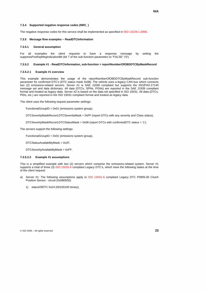
N/A
© ISO 2006 – All rights reserved 23
7.3.4 Supported negative response codes (NRC_)
The negative response codes for this service shall be implemented as specified in ISO 14229-1:2006.
7.3.5 Message flow examples – ReadDTCInformation
7.3.5.1 General assumption
For all examples the client requests to have a response message by setting the suppressPosRspMsgIndicationBit (bit 7 of the sub-function parameter) to "FALSE" ('0').
7.3.5.2 Example #1 - ReadDTCInformation, sub-function = reportNumberOfOBDDTCByMaskRecord
7.3.5.2.1 Example #1 overview
This example demonstrates the usage of the reportNumberOfOBDDTCByMaskRecord sub-function parameter for confirmed DTC's (DTC status mask 0x08). The vehicle uses a legacy CAN bus which connects two (2) emissions-related servers. Server #1 is SAE J1939 compliant but supports the ISO/PAS 27145 message set and data dictionary. All data (DTCs, SPNs, PGNs) are reported in the SAE J1939 compliant format and treated as legacy data. Server #2 is based on the data set specified in ISO 15031. All data (DTCs, PIDs, etc.) are reported in the ISO 15031 compliant format and treated as legacy data.
The client uses the following request parameter settings:
FunctionalGroupID = 0x01 (emissions system group),
DTCSeverityMaskRecord.DTCSeverityMask = 0xFF (report DTCs with any severity and Class status),
DTCSeverityMaskRecord.DTCStatusMask = 0x08 (report DTCs with confirmedDTC status = '1').
The servers support the following settings:
FunctionalGroupID = 0x01 (emissions system group),
DTCStatusAvailabilityMask = 0x2F,
DTCSeverityAvailabilityMask = 0xFF.
7.3.5.2.2 Example #1 assumptions
This is a simplified example with two (2) servers which comprise the emissions-related system. Server #1 supports a total of three (3) ISO 15031-6 compliant Legacy DTC's, which have the following states at the time of the client request:
a) Server #1: The following assumptions apply to ISO 15031-6 compliant Legacy DTC P0805-00 Clutch Position Sensor - circuit (0x080500):
1) statusOfDTC 0x24 (00100100 binary),
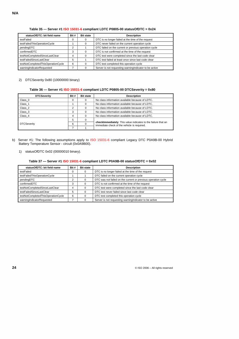
N/A
24 © ISO 2006 – All rights reserved
Table 35 — Server #1 ISO 15031-6 compliant LDTC P0805-00 statusOfDTC = 0x24
statusOfDTC: bit field name Bit # Bit state Description
testFailed 0 0 DTC is no longer failed at the time of the request
testFailedThisOperationCycle 1 0 DTC never failed on the current operation cycle pendingDTC 2 1 DTC failed on the current or previous operation cycle
confirmedDTC 3 0 DTC is not confirmed at the time of the request
testNotCompletedSinceLastClear 4 0 DTC test were completed since the last code clear testFailedSinceLastClear 5 1 DTC test failed at least once since last code clear
testNotCompletedThisOperationCycle 6 0 DTC test completed this operation cycle warningIndicatorRequested 7 0 Server is not requesting warningIndicator to be active
2) DTCSeverity 0x80 (10000000 binary)
Table 36 — Server #1 ISO 15031-6 compliant LDTC P0805-00 DTCSeverity = 0x80
DTCSeverity Bit # Bit state Description
Class_0 0 0 No class information available because of LDTC. Class_1 1 0 No class information available because of LDTC. Class_2 2 0 No class information available because of LDTC. Class_3 3 0 No class information available because of LDTC. Class_4 4 0 No class information available because of LDTC.
5 0
6 0 DTCSeverity
7 1
checkImmediately: This value indicates to the failure that an immediate check of the vehicle is required.
b) Server #1: The following assumptions apply to ISO 15031-6 compliant Legacy DTC P0A9B-00 Hybrid Battery Temperature Sensor - circuit (0x0A9B00).
1) statusOfDTC 0x02 (00000010 binary).
Table 37 — Server #1 ISO 15031-6 compliant LDTC P0A9B-00 statusOfDTC = 0x02
statusOfDTC: bit field name Bit # Bit state Description testFailed 0 0 DTC is no longer failed at the time of the request
testFailedThisOperationCycle 1 1 DTC failed on the current operation cycle
pendingDTC 2 0 DTC was not failed on the current or previous operation cycle confirmedDTC 3 0 DTC is not confirmed at the time of the request
testNotCompletedSinceLastClear 4 0 DTC test were completed since the last code clear
testFailedSinceLastClear 5 0 DTC test never failed since last code clear testNotCompletedThisOperationCycle 6 0 DTC test completed this operation cycle
warningIndicatorRequested 7 0 Server is not requesting warningIndicator to be active
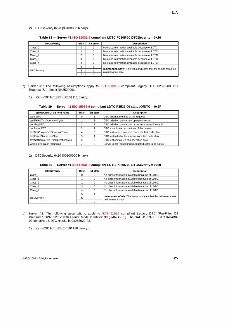
N/A
© ISO 2006 – All rights reserved 25
2) DTCSeverity 0x20 (00100000 binary)
Table 38 — Server #1 ISO 15031-6 compliant LDTC P0805-00 DTCSeverity = 0x20
DTCSeverity Bit # Bit state Description
Class_0 0 0 No class information available because of LDTC. Class_1 1 0 No class information available because of LDTC. Class_2 2 0 No class information available because of LDTC. Class_3 3 0 No class information available because of LDTC. Class_4 4 0 No class information available because of LDTC.
5 1
6 0 DTCSeverity
7 0
maintenanceOnly: This value indicates that the failure requests maintenance only.
c) Server #1: The following assumptions apply to ISO 15031-6 compliant Legacy DTC P2522-00 A/C Request “B” - circuit (0x252200).
1) statusOfDTC 0x2F (00101111 binary).
Table 39 — Server #1 ISO 15031-6 compliant LDTC P2522-00 statusOfDTC = 0x2F
statusOfDTC: bit field name Bit # Bit state Description
testFailed 0 1 DTC failed at the time of the request testFailedThisOperationCycle 1 1 DTC failed on the current operation cycle
pendingDTC 2 1 DTC failed on the current or previous operation cycle
confirmedDTC 3 1 DTC is confirmed at the time of the request testNotCompletedSinceLastClear 4 0 DTC test were completed since the last code clear
testFailedSinceLastClear 5 1 DTC test failed at least once since last code clear testNotCompletedThisOperationCycle 6 0 DTC test completed this operation cycle
warningIndicatorRequested 7 0 Server is not requesting warningIndicator to be active
2) DTCSeverity 0x20 (00100000 binary)
Table 40 — Server #1 ISO 15031-6 compliant LDTC P0805-00 DTCSeverity = 0x20
DTCSeverity Bit # Bit state Description
Class_0 0 0 No class information available because of LDTC. Class_1 1 0 No class information available because of LDTC. Class_2 2 0 No class information available because of LDTC. Class_3 3 0 No class information available because of LDTC. Class_4 4 0 No class information available because of LDTC.
5 1
6 0 DTCSeverity
7 0
maintenanceOnly: This value indicates that the failure requests maintenance only.
d) Server #2: The following assumptions apply to SAE J1939 compliant Legacy DTC "Pre-Filter Oil Pressure", SPN: 1208d with Failure Mode Identifier: 3d (0x04B8-03). The SAE J1939-73 LDTC 0x04B8-03 converted UDTC results in 0x058020-03.
1) statusOfDTC 0x2E (00101110 binary).
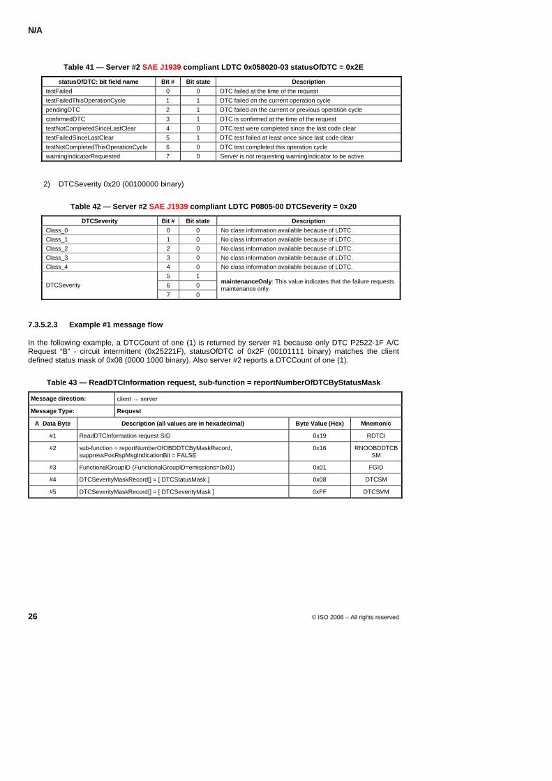
N/A
26 © ISO 2006 – All rights reserved
Table 41 — Server #2 SAE J1939 compliant LDTC 0x058020-03 statusOfDTC = 0x2E
statusOfDTC: bit field name Bit # Bit state Description
testFailed 0 0 DTC failed at the time of the request
testFailedThisOperationCycle 1 1 DTC failed on the current operation cycle pendingDTC 2 1 DTC failed on the current or previous operation cycle
confirmedDTC 3 1 DTC is confirmed at the time of the request
testNotCompletedSinceLastClear 4 0 DTC test were completed since the last code clear testFailedSinceLastClear 5 1 DTC test failed at least once since last code clear
testNotCompletedThisOperationCycle 6 0 DTC test completed this operation cycle warningIndicatorRequested 7 0 Server is not requesting warningIndicator to be active
2) DTCSeverity 0x20 (00100000 binary)
Table 42 — Server #2 SAE J1939 compliant LDTC P0805-00 DTCSeverity = 0x20
DTCSeverity Bit # Bit state Description
Class_0 0 0 No class information available because of LDTC. Class_1 1 0 No class information available because of LDTC. Class_2 2 0 No class information available because of LDTC. Class_3 3 0 No class information available because of LDTC. Class_4 4 0 No class information available because of LDTC.
5 1
6 0 DTCSeverity
7 0
maintenanceOnly: This value indicates that the failure requests maintenance only.
7.3.5.2.3 Example #1 message flow
In the following example, a DTCCount of one (1) is returned by server #1 because only DTC P2522-1F A/C Request “B” - circuit intermittent (0x25221F), statusOfDTC of 0x2F (00101111 binary) matches the client defined status mask of 0x08 (0000 1000 binary). Also server #2 reports a DTCCount of one (1).
Table 43 — ReadDTCInformation request, sub-function = reportNumberOfDTCByStatusMask
Message direction: client → server
Message Type: Request
A_Data Byte Description (all values are in hexadecimal) Byte Value (Hex) Mnemonic
#1 ReadDTCInformation request SID 0x19 RDTCI
#2 sub-function = reportNumberOfOBDDTCByMaskRecord, suppressPosRspMsgIndicationBit = FALSE
0x16 RNOOBDDTCBSM
#3 FunctionalGroupID (FunctionalGroupID=emissions=0x01) 0x01 FGID
#4 DTCSeverityMaskRecord[] = [ DTCStatusMask ] 0x08 DTCSM
#5 DTCSeverityMaskRecord[] = [ DTCSeverityMask ] 0xFF DTCSVM
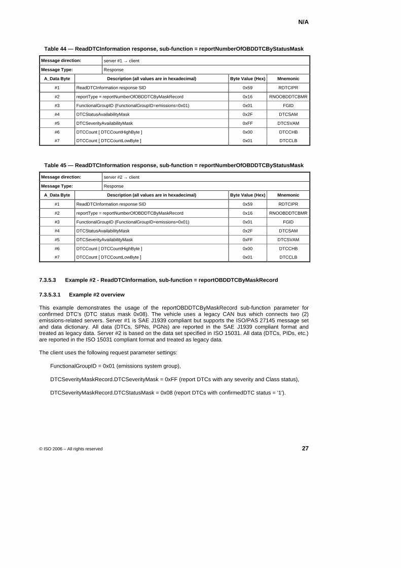
N/A
© ISO 2006 – All rights reserved 27
Table 44 — ReadDTCInformation response, sub-function = reportNumberOfOBDDTCByStatusMask
Message direction: server #1 → client
Message Type: Response
A_Data Byte Description (all values are in hexadecimal) Byte Value (Hex) Mnemonic
#1 ReadDTCInformation response SID 0x59 RDTCIPR
#2 reportType = reportNumberOfOBDDTCByMaskRecord 0x16 RNOOBDDTCBMR
#3 FunctionalGroupID (FunctionalGroupID=emissions=0x01) 0x01 FGID
#4 DTCStatusAvailabilityMask 0x2F DTCSAM
#5 DTCSeverityAvailabilityMask 0xFF DTCSVAM
#6 DTCCount [ DTCCountHighByte ] 0x00 DTCCHB
#7 DTCCount [ DTCCountLowByte ] 0x01 DTCCLB
Table 45 — ReadDTCInformation response, sub-function = reportNumberOfOBDDTCByStatusMask
Message direction: server #2 → client
Message Type: Response
A_Data Byte Description (all values are in hexadecimal) Byte Value (Hex) Mnemonic
#1 ReadDTCInformation response SID 0x59 RDTCIPR
#2 reportType = reportNumberOfOBDDTCByMaskRecord 0x16 RNOOBDDTCBMR
#3 FunctionalGroupID (FunctionalGroupID=emissions=0x01) 0x01 FGID
#4 DTCStatusAvailabilityMask 0x2F DTCSAM
#5 DTCSeverityAvailabilityMask 0xFF DTCSVAM
#6 DTCCount [ DTCCountHighByte ] 0x00 DTCCHB
#7 DTCCount [ DTCCountLowByte ] 0x01 DTCCLB
7.3.5.3 Example #2 - ReadDTCInformation, sub-function = reportOBDDTCByMaskRecord
7.3.5.3.1 Example #2 overview
This example demonstrates the usage of the reportOBDDTCByMaskRecord sub-function parameter for confirmed DTC's (DTC status mask 0x08). The vehicle uses a legacy CAN bus which connects two (2) emissions-related servers. Server #1 is SAE J1939 compliant but supports the ISO/PAS 27145 message set and data dictionary. All data (DTCs, SPNs, PGNs) are reported in the SAE J1939 compliant format and treated as legacy data. Server #2 is based on the data set specified in ISO 15031. All data (DTCs, PIDs, etc.) are reported in the ISO 15031 compliant format and treated as legacy data.
The client uses the following request parameter settings:
FunctionalGroupID = 0x01 (emissions system group),
DTCSeverityMaskRecord.DTCSeverityMask = 0xFF (report DTCs with any severity and Class status),
DTCSeverityMaskRecord.DTCStatusMask = 0x08 (report DTCs with confirmedDTC status = '1').
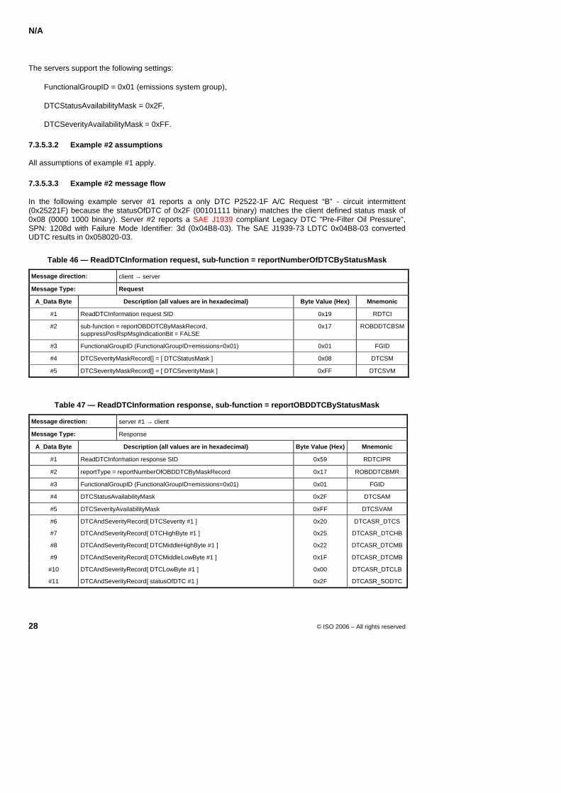
N/A
28 © ISO 2006 – All rights reserved
The servers support the following settings:
FunctionalGroupID = 0x01 (emissions system group),
DTCStatusAvailabilityMask = 0x2F,
DTCSeverityAvailabilityMask = 0xFF.
7.3.5.3.2 Example #2 assumptions
All assumptions of example #1 apply.
7.3.5.3.3 Example #2 message flow
In the following example server #1 reports a only DTC P2522-1F A/C Request “B” - circuit intermittent (0x25221F) because the statusOfDTC of 0x2F (00101111 binary) matches the client defined status mask of 0x08 (0000 1000 binary). Server #2 reports a SAE J1939 compliant Legacy DTC "Pre-Filter Oil Pressure", SPN: 1208d with Failure Mode Identifier: 3d (0x04B8-03). The SAE J1939-73 LDTC 0x04B8-03 converted UDTC results in 0x058020-03.
Table 46 — ReadDTCInformation request, sub-function = reportNumberOfDTCByStatusMask
Message direction: client → server
Message Type: Request
A_Data Byte Description (all values are in hexadecimal) Byte Value (Hex) Mnemonic
#1 ReadDTCInformation request SID 0x19 RDTCI
#2 sub-function = reportOBDDTCByMaskRecord, suppressPosRspMsgIndicationBit = FALSE
0x17 ROBDDTCBSM
#3 FunctionalGroupID (FunctionalGroupID=emissions=0x01) 0x01 FGID
#4 DTCSeverityMaskRecord[] = [ DTCStatusMask ] 0x08 DTCSM
#5 DTCSeverityMaskRecord[] = [ DTCSeverityMask ] 0xFF DTCSVM
Table 47 — ReadDTCInformation response, sub-function = reportOBDDTCByStatusMask
Message direction: server #1 → client
Message Type: Response
A_Data Byte Description (all values are in hexadecimal) Byte Value (Hex) Mnemonic
#1 ReadDTCInformation response SID 0x59 RDTCIPR
#2 reportType = reportNumberOfOBDDTCByMaskRecord 0x17 ROBDDTCBMR
#3 FunctionalGroupID (FunctionalGroupID=emissions=0x01) 0x01 FGID
#4 DTCStatusAvailabilityMask 0x2F DTCSAM
#5 DTCSeverityAvailabilityMask 0xFF DTCSVAM
#6 DTCAndSeverityRecord[ DTCSeverity #1 ] 0x20 DTCASR_DTCS
#7 DTCAndSeverityRecord[ DTCHighByte #1 ] 0x25 DTCASR_DTCHB
#8 DTCAndSeverityRecord[ DTCMiddleHighByte #1 ] 0x22 DTCASR_DTCMB
#9 DTCAndSeverityRecord[ DTCMiddleLowByte #1 ] 0x1F DTCASR_DTCMB
#10 DTCAndSeverityRecord[ DTCLowByte #1 ] 0x00 DTCASR_DTCLB
#11 DTCAndSeverityRecord[ statusOfDTC #1 ] 0x2F DTCASR_SODTC
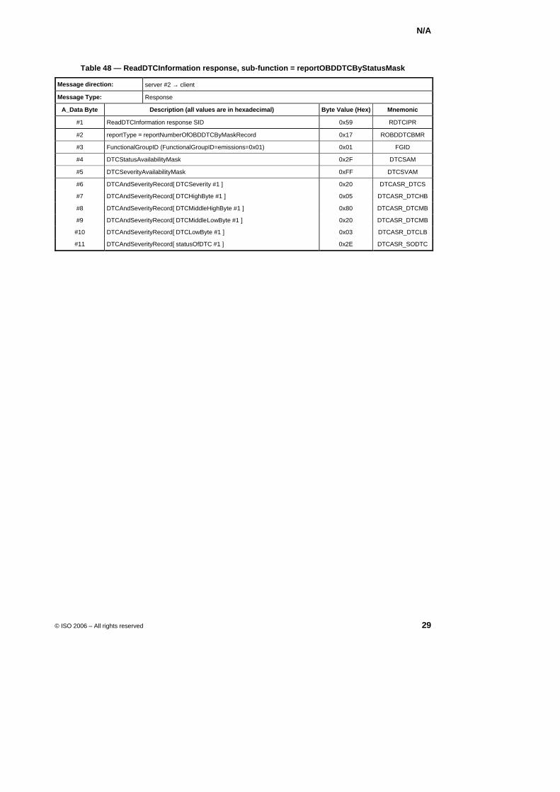
N/A
© ISO 2006 – All rights reserved 29
Table 48 — ReadDTCInformation response, sub-function = reportOBDDTCByStatusMask
Message direction: server #2 → client
Message Type: Response
A_Data Byte Description (all values are in hexadecimal) Byte Value (Hex) Mnemonic
#1 ReadDTCInformation response SID 0x59 RDTCIPR
#2 reportType = reportNumberOfOBDDTCByMaskRecord 0x17 ROBDDTCBMR
#3 FunctionalGroupID (FunctionalGroupID=emissions=0x01) 0x01 FGID
#4 DTCStatusAvailabilityMask 0x2F DTCSAM
#5 DTCSeverityAvailabilityMask 0xFF DTCSVAM
#6 DTCAndSeverityRecord[ DTCSeverity #1 ] 0x20 DTCASR_DTCS
#7 DTCAndSeverityRecord[ DTCHighByte #1 ] 0x05 DTCASR_DTCHB
#8 DTCAndSeverityRecord[ DTCMiddleHighByte #1 ] 0x80 DTCASR_DTCMB
#9 DTCAndSeverityRecord[ DTCMiddleLowByte #1 ] 0x20 DTCASR_DTCMB
#10 DTCAndSeverityRecord[ DTCLowByte #1 ] 0x03 DTCASR_DTCLB
#11 DTCAndSeverityRecord[ statusOfDTC #1 ] 0x2E DTCASR_SODTC
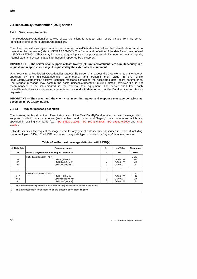
N/A
30 © ISO 2006 – All rights reserved
7.4 ReadDataByDataIdentifier (0x22) service
7.4.1 Service requirements
The ReadDataByDataIdentifier service allows the client to request data record values from the server identified by one or more unifiedDataIdentifiers.
The client request message contains one or more unifiedDataIdentifier values that identify data record(s) maintained by the server (refer to ISO/PAS 27145-2). The format and definition of the dataRecord are defined in ISO/PAS 27145-2. Those may include analogue input and output signals, digital input and output signals, internal data, and system status information if supported by the server.
IMPORTANT — The server shall support at least twenty (20) unifiedDataIdentifiers simultaneously in a request and response message if requested by the external test equipment.
Upon receiving a ReadDataByDataIdentifier request, the server shall access the data elements of the records specified by the unifiedDataIdentifier parameter(s) and transmit their value in one single ReadDataByDataIdentifier positive response message containing the associated dataRecord parameter(s). The request message may contain the same unifiedDataIdentifier multiple times, however this is not recommended to be implemented in the external test equipment. The server shall treat each unifiedDataIdentifier as a separate parameter and respond with data for each unifiedDataIdentifier as often as requested.
IMPORTANT — The server and the client shall meet the request and response message behaviour as specified in ISO 14229-1:2006.
7.4.1.1 Request message definition
The following tables show the different structures of the ReadDataByDataIdentifier request message, which supports "unified" data parameters (standardised world wide) and "legacy" data parameters which are specified in existing standards (e.g. ISO 14229-1:2006, ISO 15031-5:2006, ISO 15031-6:2005 and SAE J1939).
Table 49 specifies the request message format for any type of data identifier described in Table 50 including one or multiple UDID(s). The UDID can be set to any data type of "unified" or "legacy" data interpretation.
Table 49 — Request message definition with UDID(s)
A_Data Byte Parameter Name Cvt Hex Value Mnemonic
#1 ReadDataByDataIdentifier Request Service Id M 0x22 RDBI
#2 #3 #4
unifiedDataIdentifier[] #1 = [ UDIDHighByte #1 UDIDMiddleByte #1 UDIDLowByte #1 ]
M M M
0x00-0xFF 0x00-0xFF 0x00-0xFF
UDID_ HB MB LB
: : : : :
#n-2 #n-1 #n
unifiedDataIdentifier[] #m = [ UDIDHighByte #m UDIDMiddleByte #m UDIDLowByte #m ]
U C C
0x00-0xFF 0x00-0xFF 0x00-0xFF
UDID_ HB MB LB
U: This parameter is only present if more than one (1) UnifiedDataIdentifier is requested.
C: This parameter is present depending on the presence of the preceding byte.
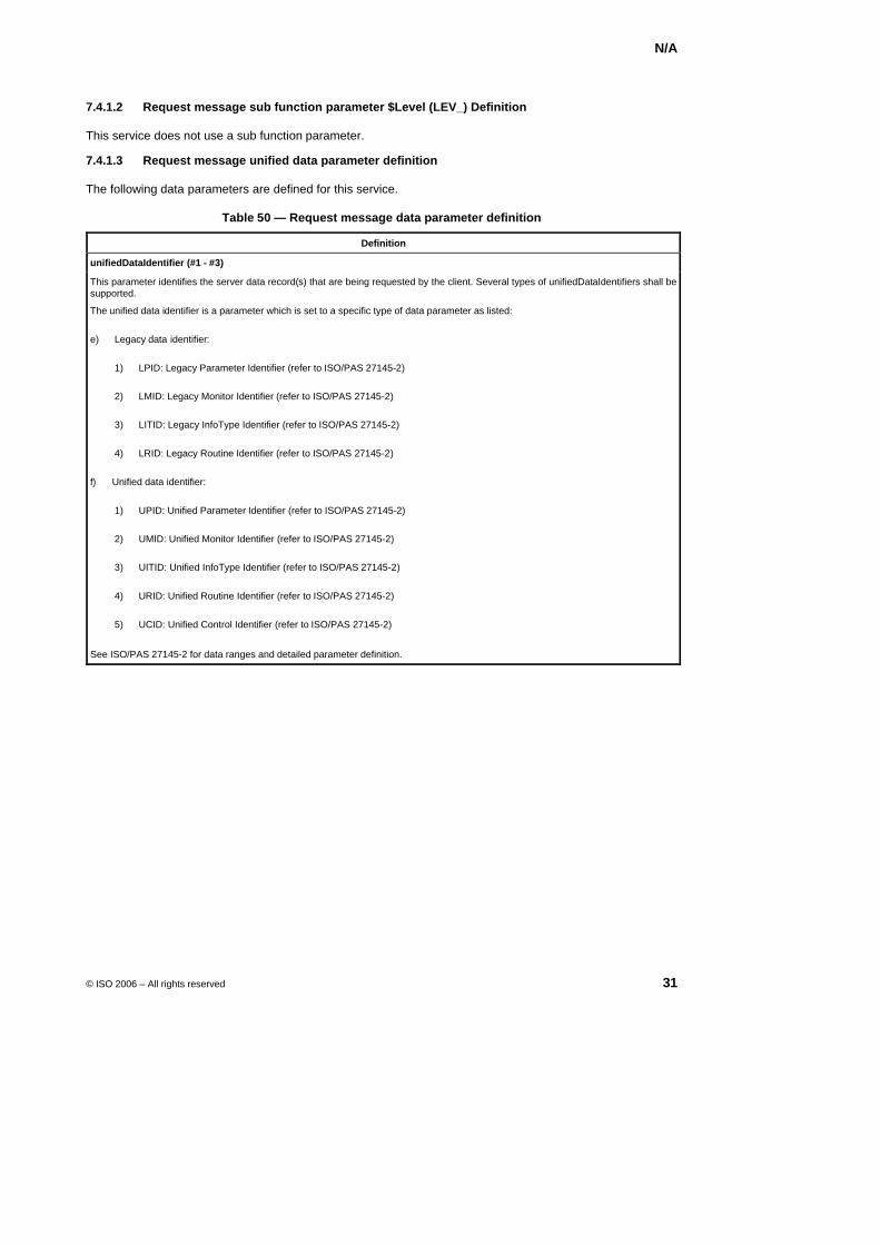
N/A
© ISO 2006 – All rights reserved 31
7.4.1.2 Request message sub function parameter $Level (LEV_) Definition
This service does not use a sub function parameter.
7.4.1.3 Request message unified data parameter definition
The following data parameters are defined for this service.
Table 50 — Request message data parameter definition
Definition
unifiedDataIdentifier (#1 - #3)
This parameter identifies the server data record(s) that are being requested by the client. Several types of unifiedDataIdentifiers shall be supported.
The unified data identifier is a parameter which is set to a specific type of data parameter as listed:
e) Legacy data identifier:
1) LPID: Legacy Parameter Identifier (refer to ISO/PAS 27145-2)
2) LMID: Legacy Monitor Identifier (refer to ISO/PAS 27145-2)
3) LITID: Legacy InfoType Identifier (refer to ISO/PAS 27145-2)
4) LRID: Legacy Routine Identifier (refer to ISO/PAS 27145-2)
f) Unified data identifier:
1) UPID: Unified Parameter Identifier (refer to ISO/PAS 27145-2)
2) UMID: Unified Monitor Identifier (refer to ISO/PAS 27145-2)
3) UITID: Unified InfoType Identifier (refer to ISO/PAS 27145-2)
4) URID: Unified Routine Identifier (refer to ISO/PAS 27145-2)
5) UCID: Unified Control Identifier (refer to ISO/PAS 27145-2)
See ISO/PAS 27145-2 for data ranges and detailed parameter definition.
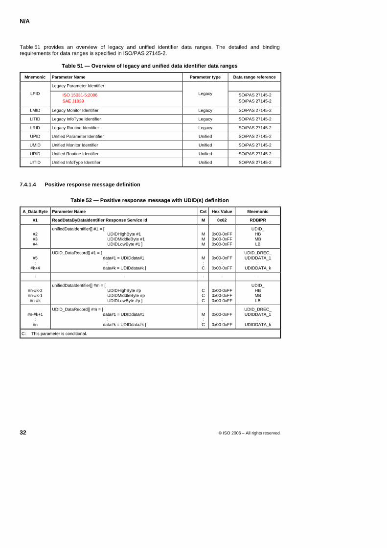
N/A
32 © ISO 2006 – All rights reserved
Table 51 provides an overview of legacy and unified identifier data ranges. The detailed and binding requirements for data ranges is specified in ISO/PAS 27145-2.
Table 51 — Overview of legacy and unified data identifier data ranges
Mnemonic Parameter Name Parameter type Data range reference
Legacy Parameter Identifier
LPID ISO 15031-5:2006 SAE J1939
Legacy ISO/PAS 27145-2 ISO/PAS 27145-2
LMID Legacy Monitor Identifier Legacy ISO/PAS 27145-2
LITID Legacy InfoType Identifier Legacy ISO/PAS 27145-2
LRID Legacy Routine Identifier Legacy ISO/PAS 27145-2
UPID Unified Parameter Identifier Unified ISO/PAS 27145-2
UMID Unified Monitor Identifier Unified ISO/PAS 27145-2
URID Unified Routine Identifier Unified ISO/PAS 27145-2
UITID Unified InfoType Identifier Unified ISO/PAS 27145-2
7.4.1.4 Positive response message definition
Table 52 — Positive response message with UDID(s) definition
A_Data Byte Parameter Name Cvt Hex Value Mnemonic
#1 ReadDataByDataIdentifier Response Service Id M 0x62 RDBIPR
#2 #3 #4
unifiedDataIdentifier[] #1 = [ UDIDHighByte #1 UDIDMiddleByte #1 UDIDLowByte #1 ]
M M M
0x00-0xFF 0x00-0xFF 0x00-0xFF
UDID_ HB MB LB
#5 :
#k+4
UDID_DataRecord[] #1 = [ data#1 = UDIDdata#1 : data#k = UDIDdata#k ]
M : C
0x00-0xFF
: 0x00-0xFF
UDID_DREC_ UDIDDATA_1
: UDIDDATA_k
: : : : :
#n-#k-2 #n-#k-1 #n-#k
unifiedDataIdentifier[] #m = [ UDIDHighByte #p UDIDMiddleByte #p UDIDLowByte #p ]
C C C
0x00-0xFF 0x00-0xFF 0x00-0xFF
UDID_ HB MB LB
#n-#k+1
: #n
UDID_DataRecord[] #m = [ data#1 = UDIDdata#1 : data#k = UDIDdata#k ]
M : C
0x00-0xFF
: 0x00-0xFF
UDID_DREC_ UDIDDATA_1
: UDIDDATA_k
C: This parameter is conditional.
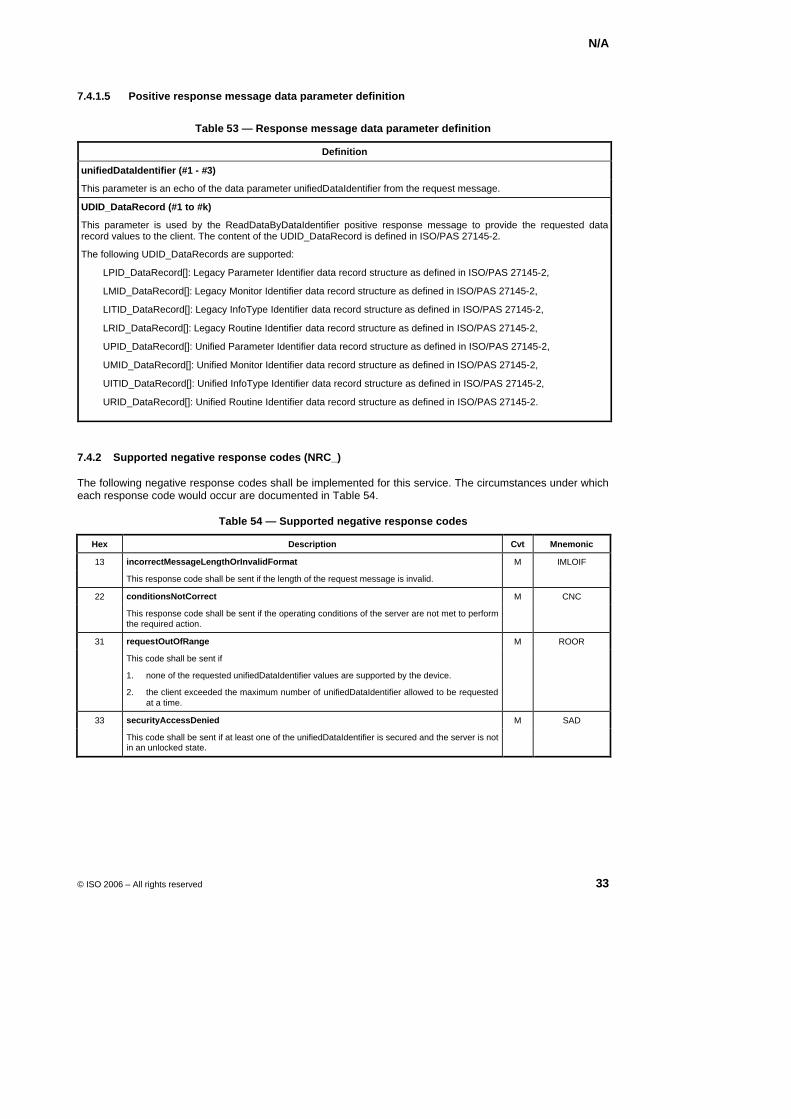
N/A
© ISO 2006 – All rights reserved 33
7.4.1.5 Positive response message data parameter definition
Table 53 — Response message data parameter definition
Definition
unifiedDataIdentifier (#1 - #3)
This parameter is an echo of the data parameter unifiedDataIdentifier from the request message.
UDID_DataRecord (#1 to #k)
This parameter is used by the ReadDataByDataIdentifier positive response message to provide the requested data record values to the client. The content of the UDID_DataRecord is defined in ISO/PAS 27145-2.
The following UDID_DataRecords are supported:
LPID_DataRecord[]: Legacy Parameter Identifier data record structure as defined in ISO/PAS 27145-2,
LMID_DataRecord[]: Legacy Monitor Identifier data record structure as defined in ISO/PAS 27145-2,
LITID_DataRecord[]: Legacy InfoType Identifier data record structure as defined in ISO/PAS 27145-2,
LRID_DataRecord[]: Legacy Routine Identifier data record structure as defined in ISO/PAS 27145-2,
UPID_DataRecord[]: Unified Parameter Identifier data record structure as defined in ISO/PAS 27145-2,
UMID_DataRecord[]: Unified Monitor Identifier data record structure as defined in ISO/PAS 27145-2,
UITID_DataRecord[]: Unified InfoType Identifier data record structure as defined in ISO/PAS 27145-2,
URID_DataRecord[]: Unified Routine Identifier data record structure as defined in ISO/PAS 27145-2.
7.4.2 Supported negative response codes (NRC_)
The following negative response codes shall be implemented for this service. The circumstances under which each response code would occur are documented in Table 54.
Table 54 — Supported negative response codes
Hex Description Cvt Mnemonic
13 incorrectMessageLengthOrInvalidFormat M IMLOIF
This response code shall be sent if the length of the request message is invalid.
22 conditionsNotCorrect M CNC
This response code shall be sent if the operating conditions of the server are not met to perform the required action.
31 requestOutOfRange M ROOR
This code shall be sent if
1. none of the requested unifiedDataIdentifier values are supported by the device.
2. the client exceeded the maximum number of unifiedDataIdentifier allowed to be requested at a time.
33 securityAccessDenied M SAD
This code shall be sent if at least one of the unifiedDataIdentifier is secured and the server is not in an unlocked state.
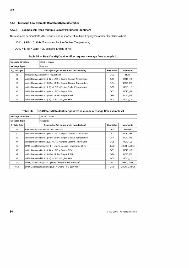
N/A
34 © ISO 2006 – All rights reserved
7.4.3 Message flow example ReadDataByDataIdentifier
7.4.3.1 Example #1: Read multiple Legacy Parameter Identifiers
This example demonstrates the request and response of multiple Legacy Parameter Identifiers where:
UDID = LPID = 0x10F405 contains Engine Coolant Temperature,
UDID = LPID = 0x10F40C contains Engine RPM.
Table 55 — ReadDataByDataIdentifier request message flow example #1
Message direction: client → server
Message Type: Request
A_Data byte Description (all values are in hexadecimal) Hex Value Mnemonic
#1 ReadDataByDataIdentifier request SID 0x22 RDBI
#2 unifiedDataIdentifier #1 (HB) = LPID = Engine Coolant Temperature 0x01 UDID_HB
#3 unifiedDataIdentifier #1 (MB) = LPID = Engine Coolant Temperature 0xF4 UDID_MB
#4 unifiedDataIdentifier #1 (LB) = LPID = Engine Coolant Temperature 0x05 UDID_LB
#5 unifiedDataIdentifier #2 (HB) = LPID = Engine RPM 0x01 UDID_HB
#6 unifiedDataIdentifier #2 (MB) = LPID = Engine RPM 0xF4 UDID_MB
#7 unifiedDataIdentifier #2 (LB) = LPID = Engine RPM 0x0C UDID_LB
Table 56 — ReadDataByDataIdentifier positive response message flow example #1
Message direction: server → client
Message Type: Response
A_Data Byte Description (all values are in hexadecimal) Hex Value Mnemonic
#1 ReadDataByDataIdentifier response SID 0x62 RDBIPR
#2 unifiedDataIdentifier #1 (HB) = LPID = Engine Coolant Temperature 0x01 UDID_HB
#3 unifiedDataIdentifier #1 (MB) = LPID = Engine Coolant Temperature 0xF4 UDID_MB
#4 unifiedDataIdentifier #1 (LB) = LPID = Engine Coolant Temperature 0x05 UDID_LB
#5 LPID_DataRecord[ data#1 ] = Engine Coolant Temperature 85 °C 0x2D DREC_DATA1
#6 unifiedDataIdentifier #2 (HB) = LPID = Engine RPM 0x01 UDID_HB
#7 unifiedDataIdentifier #2 (MB) = LPID = Engine RPM 0xF4 UDID_MB
#8 unifiedDataIdentifier #2 (LB) = LPID = Engine RPM 0x0C UDID_LB
#9 LPID_DataRecord[ data#1 ] (HB) = Engine RPM 1500 min-1 0x17 DREC_DATA1
#10 LPID_DataRecord[ data#2 ] (LB) = Engine RPM 1500 min-1 0x70 DREC_DATA2
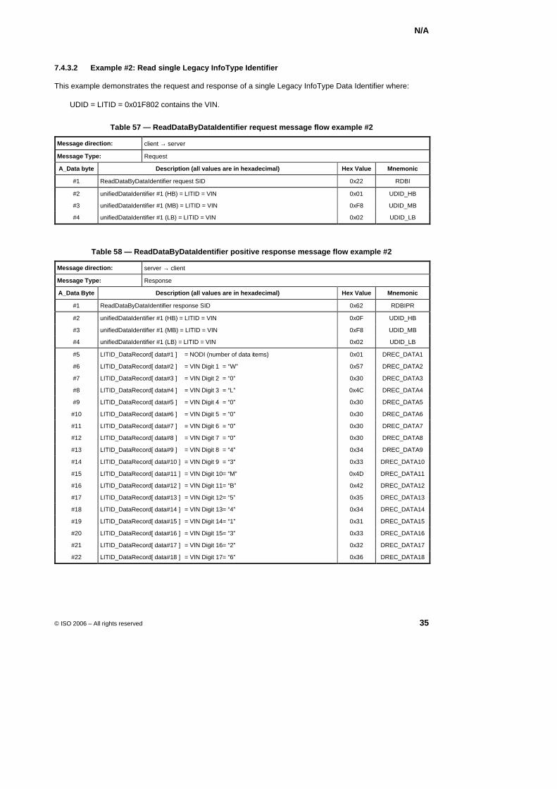
N/A
© ISO 2006 – All rights reserved 35
7.4.3.2 Example #2: Read single Legacy InfoType Identifier
This example demonstrates the request and response of a single Legacy InfoType Data Identifier where:
UDID = LITID = 0x01F802 contains the VIN.
Table 57 — ReadDataByDataIdentifier request message flow example #2
Message direction: client → server
Message Type: Request
A_Data byte Description (all values are in hexadecimal) Hex Value Mnemonic
#1 ReadDataByDataIdentifier request SID 0x22 RDBI
#2 unifiedDataIdentifier #1 (HB) = LITID = VIN 0x01 UDID_HB
#3 unifiedDataIdentifier #1 (MB) = LITID = VIN 0xF8 UDID_MB
#4 unifiedDataIdentifier #1 (LB) = LITID = VIN 0x02 UDID_LB
Table 58 — ReadDataByDataIdentifier positive response message flow example #2
Message direction: server → client
Message Type: Response
A_Data Byte Description (all values are in hexadecimal) Hex Value Mnemonic
#1 ReadDataByDataIdentifier response SID 0x62 RDBIPR
#2 unifiedDataIdentifier #1 (HB) = LITID = VIN 0x0F UDID_HB
#3 unifiedDataIdentifier #1 (MB) = LITID = VIN 0xF8 UDID_MB
#4 unifiedDataIdentifier #1 (LB) = LITID = VIN 0x02 UDID_LB
#5 LITID_DataRecord[ data#1 ] = NODI (number of data items) 0x01 DREC_DATA1
#6 LITID_DataRecord[ data#2 ] = VIN Digit 1 = “W” 0x57 DREC_DATA2
#7 LITID_DataRecord[ data#3 ] = VIN Digit 2 = “0” 0x30 DREC_DATA3
#8 LITID_DataRecord[ data#4 ] = VIN Digit 3 = “L” 0x4C DREC_DATA4
#9 LITID_DataRecord[ data#5 ] = VIN Digit 4 = “0” 0x30 DREC_DATA5
#10 LITID_DataRecord[ data#6 ] = VIN Digit 5 = “0” 0x30 DREC_DATA6
#11 LITID_DataRecord[ data#7 ] = VIN Digit 6 = “0” 0x30 DREC_DATA7
#12 LITID_DataRecord[ data#8 ] = VIN Digit 7 = “0” 0x30 DREC_DATA8
#13 LITID_DataRecord[ data#9 ] = VIN Digit 8 = “4” 0x34 DREC_DATA9
#14 LITID_DataRecord[ data#10 ] = VIN Digit 9 = “3” 0x33 DREC_DATA10
#15 LITID_DataRecord[ data#11 ] = VIN Digit 10= “M” 0x4D DREC_DATA11
#16 LITID_DataRecord[ data#12 ] = VIN Digit 11= “B” 0x42 DREC_DATA12
#17 LITID_DataRecord[ data#13 ] = VIN Digit 12= “5” 0x35 DREC_DATA13
#18 LITID_DataRecord[ data#14 ] = VIN Digit 13= “4” 0x34 DREC_DATA14
#19 LITID_DataRecord[ data#15 ] = VIN Digit 14= “1” 0x31 DREC_DATA15
#20 LITID_DataRecord[ data#16 ] = VIN Digit 15= “3” 0x33 DREC_DATA16
#21 LITID_DataRecord[ data#17 ] = VIN Digit 16= “2” 0x32 DREC_DATA17
#22 LITID_DataRecord[ data#18 ] = VIN Digit 17= “6” 0x36 DREC_DATA18
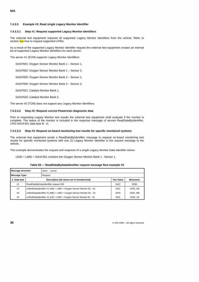
N/A
36 © ISO 2006 – All rights reserved
7.4.3.3 Example #3: Read single Legacy Monitor Identifier
7.4.3.3.1 Step #1: Request supported Legacy Monitor Identifiers
The external test equipment requests all supported Legacy Monitor Identifiers from the vehicle. Refer to section xxx how to request supported LPIDs.
As a result of the supported Legacy Monitor Identifier request the external test equipment creates an internal list of supported Legacy Monitor Identifiers for each server:
The server #1 (ECM) supports Legacy Monitor Identifiers:
0x01F601: Oxygen Sensor Monitor Bank 1 – Sensor 1,
0x01F602: Oxygen Sensor Monitor Bank 1 – Sensor 2,
0x01F605: Oxygen Sensor Monitor Bank 2 – Sensor 1,
0x01F606: Oxygen Sensor Monitor Bank 2 – Sensor 2,
0x01F621: Catalyst Monitor Bank 1,
0x01F622: Catalyst Monitor Bank 2.
The server #2 (TCM) does not support any Legacy Monitor Identifiers.
7.4.3.3.2 Step #2: Request current Powertrain diagnostic data
Prior to requesting Legacy Monitor test results the external test equipment shall evaluate if the monitor is complete. The status of the monitor is included in the response message of service ReadDataByIdentifier, LPID 0x01F401 data byte B - D.
7.4.3.3.3 Step #3: Request on-board monitoring test results for specific monitored systems
The external test equipment sends a ReadDataByIdentifier message to request on-board monitoring test results for specific monitored systems with one (1) Legacy Monitor Identifier in the request message to the vehicle.
This example demonstrates the request and response of a single Legacy Monitor Data Identifier where:
UDID = LMID = 0x01F601 contains the Oxygen Sensor Monitor Bank 1 - Sensor 1.
Table 59 — ReadDataByDataIdentifier request message flow example #3
Message direction: client → server
Message Type: Request
A_Data byte Description (all values are in hexadecimal) Hex Value Mnemonic
#1 ReadDataByDataIdentifier request SID 0x22 RDBI
#2 unifiedDataIdentifier #1 (HB) = LMID = Oxygen Sensor Monitor B1 - S1 0x01 UDID_HB
#3 unifiedDataIdentifier #1 (MB) = LMID = Oxygen Sensor Monitor B1 - S1 0xF6 UDID_MB
#4 unifiedDataIdentifier #1 (LB) = LMID = Oxygen Sensor Monitor B1 - S1 0x01 UDID_LB
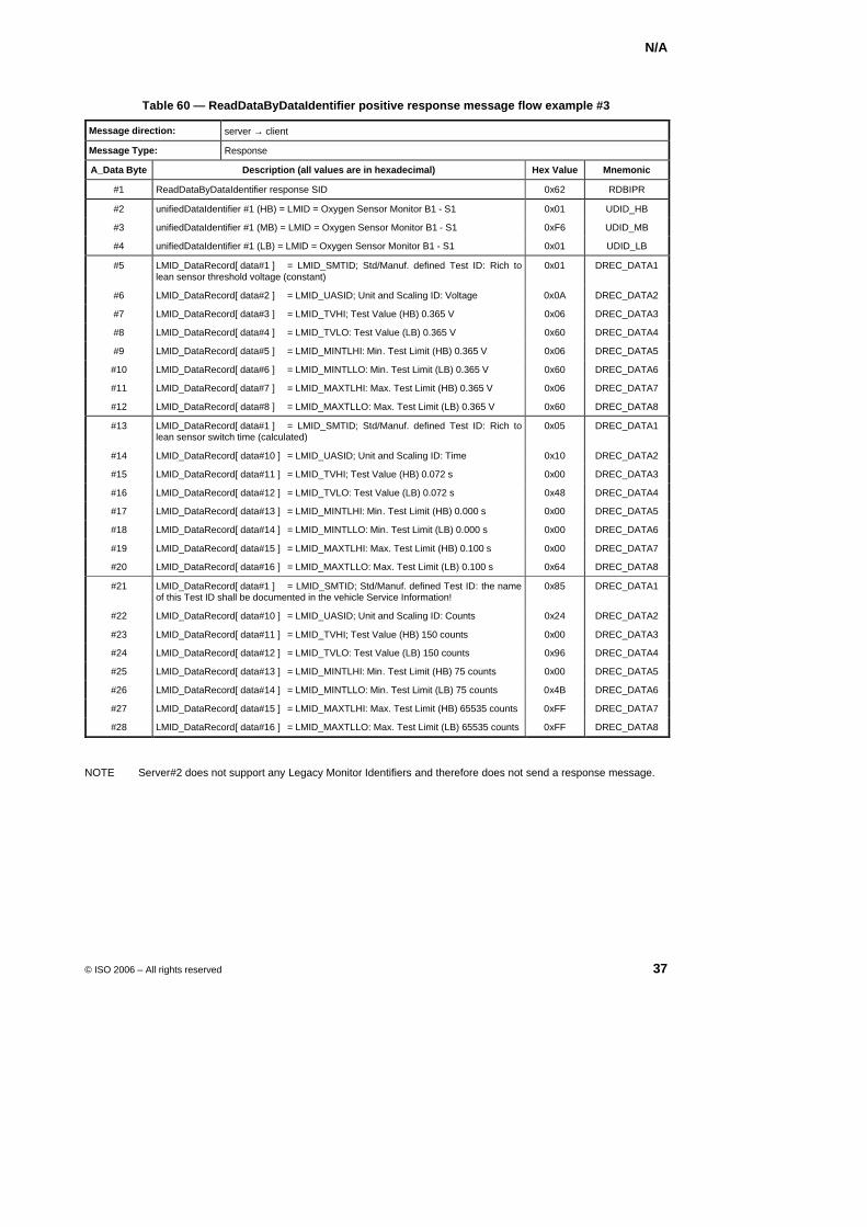
N/A
© ISO 2006 – All rights reserved 37
Table 60 — ReadDataByDataIdentifier positive response message flow example #3
Message direction: server → client
Message Type: Response
A_Data Byte Description (all values are in hexadecimal) Hex Value Mnemonic
#1 ReadDataByDataIdentifier response SID 0x62 RDBIPR
#2 unifiedDataIdentifier #1 (HB) = LMID = Oxygen Sensor Monitor B1 - S1 0x01 UDID_HB
#3 unifiedDataIdentifier #1 (MB) = LMID = Oxygen Sensor Monitor B1 - S1 0xF6 UDID_MB
#4 unifiedDataIdentifier #1 (LB) = LMID = Oxygen Sensor Monitor B1 - S1 0x01 UDID_LB
#5 LMID_DataRecord[ data#1 ] = LMID_SMTID; Std/Manuf. defined Test ID: Rich to lean sensor threshold voltage (constant)
0x01 DREC_DATA1
#6 LMID_DataRecord[ data#2 ] = LMID_UASID; Unit and Scaling ID: Voltage 0x0A DREC_DATA2
#7 LMID_DataRecord[ data#3 ] = LMID_TVHI; Test Value (HB) 0.365 V 0x06 DREC_DATA3
#8 LMID_DataRecord[ data#4 ] = LMID_TVLO: Test Value (LB) 0.365 V 0x60 DREC_DATA4
#9 LMID_DataRecord[ data#5 ] = LMID_MINTLHI: Min. Test Limit (HB) 0.365 V 0x06 DREC_DATA5
#10 LMID_DataRecord[ data#6 ] = LMID_MINTLLO: Min. Test Limit (LB) 0.365 V 0x60 DREC_DATA6
#11 LMID_DataRecord[ data#7 ] = LMID_MAXTLHI: Max. Test Limit (HB) 0.365 V 0x06 DREC_DATA7
#12 LMID_DataRecord[ data#8 ] = LMID_MAXTLLO: Max. Test Limit (LB) 0.365 V 0x60 DREC_DATA8
#13 LMID_DataRecord[ data#1 ] = LMID_SMTID; Std/Manuf. defined Test ID: Rich to lean sensor switch time (calculated)
0x05 DREC_DATA1
#14 LMID_DataRecord[ data#10 ] = LMID_UASID; Unit and Scaling ID: Time 0x10 DREC_DATA2
#15 LMID_DataRecord[ data#11 ] = LMID_TVHI; Test Value (HB) 0.072 s 0x00 DREC_DATA3
#16 LMID_DataRecord[ data#12 ] = LMID_TVLO: Test Value (LB) 0.072 s 0x48 DREC_DATA4
#17 LMID_DataRecord[ data#13 ] = LMID_MINTLHI: Min. Test Limit (HB) 0.000 s 0x00 DREC_DATA5
#18 LMID_DataRecord[ data#14 ] = LMID_MINTLLO: Min. Test Limit (LB) 0.000 s 0x00 DREC_DATA6
#19 LMID_DataRecord[ data#15 ] = LMID_MAXTLHI: Max. Test Limit (HB) 0.100 s 0x00 DREC_DATA7
#20 LMID_DataRecord[ data#16 ] = LMID_MAXTLLO: Max. Test Limit (LB) 0.100 s 0x64 DREC_DATA8
#21 LMID_DataRecord[ data#1 ] = LMID_SMTID; Std/Manuf. defined Test ID: the name of this Test ID shall be documented in the vehicle Service Information!
0x85 DREC_DATA1
#22 LMID_DataRecord[ data#10 ] = LMID_UASID; Unit and Scaling ID: Counts 0x24 DREC_DATA2
#23 LMID_DataRecord[ data#11 ] = LMID_TVHI; Test Value (HB) 150 counts 0x00 DREC_DATA3
#24 LMID_DataRecord[ data#12 ] = LMID_TVLO: Test Value (LB) 150 counts 0x96 DREC_DATA4
#25 LMID_DataRecord[ data#13 ] = LMID_MINTLHI: Min. Test Limit (HB) 75 counts 0x00 DREC_DATA5
#26 LMID_DataRecord[ data#14 ] = LMID_MINTLLO: Min. Test Limit (LB) 75 counts 0x4B DREC_DATA6
#27 LMID_DataRecord[ data#15 ] = LMID_MAXTLHI: Max. Test Limit (HB) 65535 counts 0xFF DREC_DATA7
#28 LMID_DataRecord[ data#16 ] = LMID_MAXTLLO: Max. Test Limit (LB) 65535 counts 0xFF DREC_DATA8
NOTE Server#2 does not support any Legacy Monitor Identifiers and therefore does not send a response message.
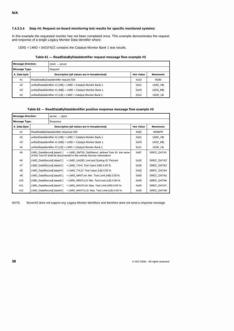
N/A
38 © ISO 2006 – All rights reserved
7.4.3.3.4 Step #4: Request on-board monitoring test results for specific monitored systems
In this example the requested monitor has not been completed once. This example demonstrates the request and response of a single Legacy Monitor Data Identifier where:
UDID = LMID = 0x01F621 contains the Catalyst Monitor Bank 1 test results.
Table 61 — ReadDataByDataIdentifier request message flow example #3
Message direction: client → server
Message Type: Request
A_Data byte Description (all values are in hexadecimal) Hex Value Mnemonic
#1 ReadDataByDataIdentifier request SID 0x22 RDBI
#2 unifiedDataIdentifier #1 (HB) = LMID = Catalyst Monitor Bank 1 0x01 UDID_HB
#3 unifiedDataIdentifier #1 (MB) = LMID = Catalyst Monitor Bank 1 0xF6 UDID_MB
#4 unifiedDataIdentifier #1 (LB) = LMID = Catalyst Monitor Bank 1 0x21 UDID_LB
Table 62 — ReadDataByDataIdentifier positive response message flow example #3
Message direction: server → client
Message Type: Response
A_Data Byte Description (all values are in hexadecimal) Hex Value Mnemonic
#1 ReadDataByDataIdentifier response SID 0x62 RDBIPR
#2 unifiedDataIdentifier #1 (HB) = LMID = Catalyst Monitor Bank 1 0x01 UDID_HB
#3 unifiedDataIdentifier #1 (MB) = LMID = Catalyst Monitor Bank 1 0xF6 UDID_MB
#4 unifiedDataIdentifier #1 (LB) = LMID = Catalyst Monitor Bank 1 0x21 UDID_LB
#5 LMID_DataRecord[ data#1 ] = LMID_SMTID; Std/Manuf. defined Test ID: the name of this Test ID shall be documented in the vehicle Service Information!
0x87 DREC_DATA1
#6 LMID_DataRecord[ data#2 ] = LMID_UASID; Unit and Scaling ID: Percent 0x2E DREC_DATA2
#7 LMID_DataRecord[ data#3 ] = LMID_TVHI; Test Value (HB) 0.00 % 0x00 DREC_DATA3
#8 LMID_DataRecord[ data#4 ] = LMID_TVLO: Test Value (LB) 0.00 % 0x00 DREC_DATA4
#9 LMID_DataRecord[ data#5 ] = LMID_MINTLHI: Min. Test Limit (HB) 0.00 % 0x00 DREC_DATA5
#10 LMID_DataRecord[ data#6 ] = LMID_MINTLLO: Min. Test Limit (LB) 0.00 % 0x00 DREC_DATA6
#11 LMID_DataRecord[ data#7 ] = LMID_MAXTLHI: Max. Test Limit (HB) 0.00 % 0x00 DREC_DATA7
#12 LMID_DataRecord[ data#8 ] = LMID_MAXTLLO: Max. Test Limit (LB) 0.00 % 0x00 DREC_DATA8
NOTE Server#2 does not support any Legacy Monitor Identifiers and therefore does not send a response message.
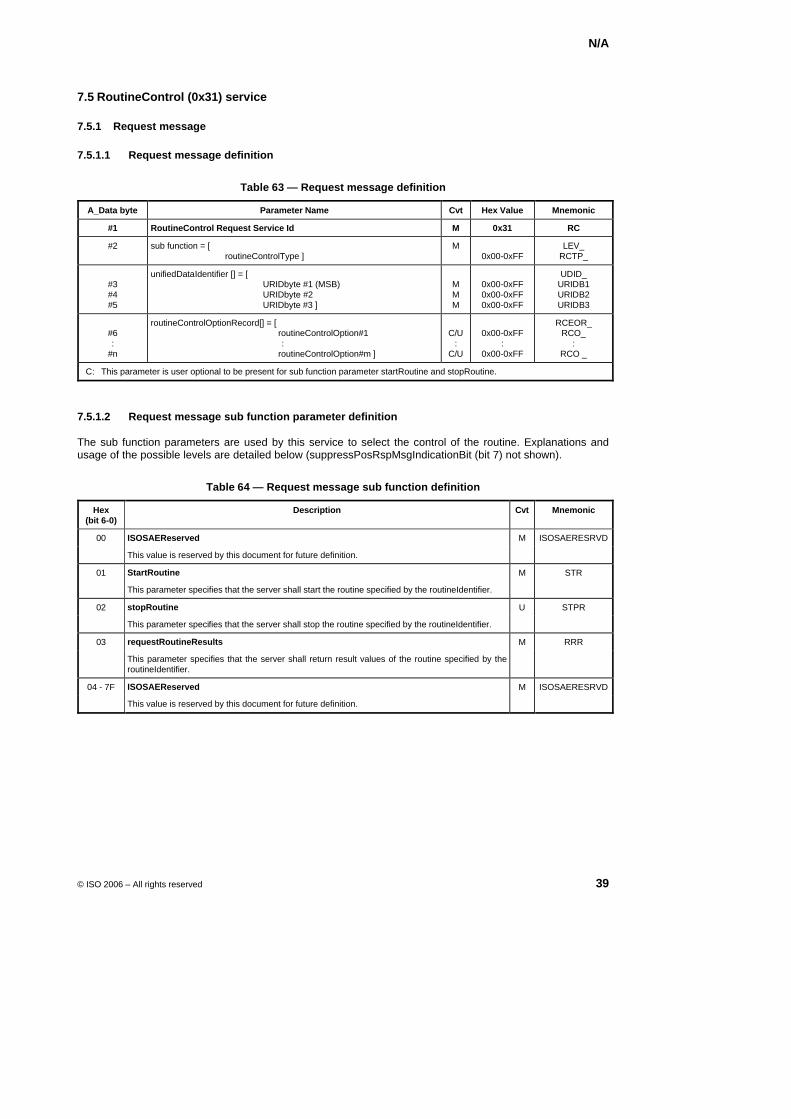
N/A
© ISO 2006 – All rights reserved 39
7.5 RoutineControl (0x31) service
7.5.1 Request message
7.5.1.1 Request message definition
Table 63 — Request message definition
A_Data byte Parameter Name Cvt Hex Value Mnemonic
#1 RoutineControl Request Service Id M 0x31 RC
#2 sub function = [ routineControlType ]
M 0x00-0xFF
LEV_ RCTP_
#3 #4 #5
unifiedDataIdentifier [] = [ URIDbyte #1 (MSB) URIDbyte #2 URIDbyte #3 ]
M M M
0x00-0xFF 0x00-0xFF 0x00-0xFF
UDID_ URIDB1 URIDB2 URIDB3
#6 :
#n
routineControlOptionRecord[] = [ routineControlOption#1 : routineControlOption#m ]
C/U
: C/U
0x00-0xFF
: 0x00-0xFF
RCEOR_ RCO_
: RCO _
C: This parameter is user optional to be present for sub function parameter startRoutine and stopRoutine.
7.5.1.2 Request message sub function parameter definition
The sub function parameters are used by this service to select the control of the routine. Explanations and usage of the possible levels are detailed below (suppressPosRspMsgIndicationBit (bit 7) not shown).
Table 64 — Request message sub function definition
Hex (bit 6-0)
Description Cvt Mnemonic
00 ISOSAEReserved M ISOSAERESRVD
This value is reserved by this document for future definition.
01 StartRoutine M STR
This parameter specifies that the server shall start the routine specified by the routineIdentifier.
02 stopRoutine U STPR
This parameter specifies that the server shall stop the routine specified by the routineIdentifier.
03 requestRoutineResults M RRR
This parameter specifies that the server shall return result values of the routine specified by the routineIdentifier.
04 - 7F ISOSAEReserved M ISOSAERESRVD
This value is reserved by this document for future definition.
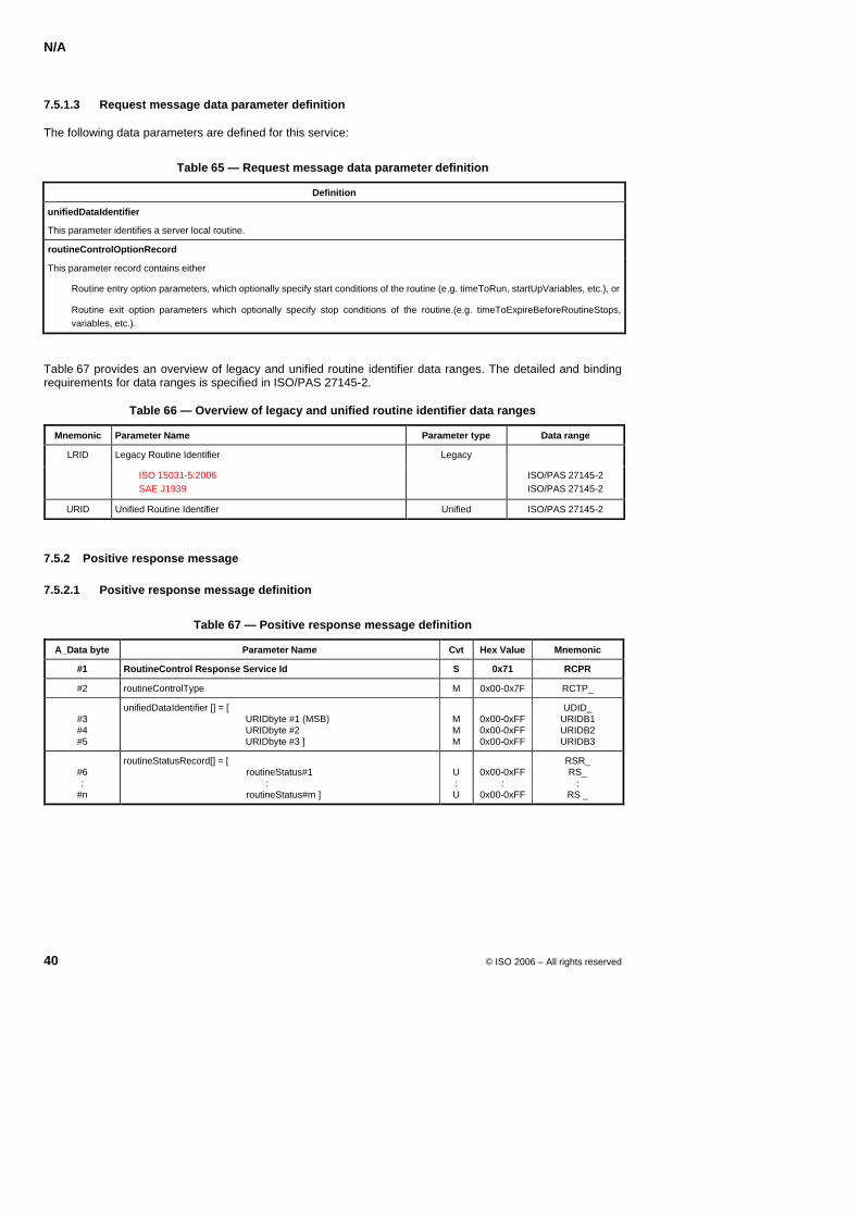
N/A
40 © ISO 2006 – All rights reserved
7.5.1.3 Request message data parameter definition
The following data parameters are defined for this service:
Table 65 — Request message data parameter definition
Definition
unifiedDataIdentifier
This parameter identifies a server local routine.
routineControlOptionRecord
This parameter record contains either
Routine entry option parameters, which optionally specify start conditions of the routine (e.g. timeToRun, startUpVariables, etc.), or
Routine exit option parameters which optionally specify stop conditions of the routine.(e.g. timeToExpireBeforeRoutineStops, variables, etc.).
Table 67 provides an overview of legacy and unified routine identifier data ranges. The detailed and binding requirements for data ranges is specified in ISO/PAS 27145-2.
Table 66 — Overview of legacy and unified routine identifier data ranges
Mnemonic Parameter Name Parameter type Data range
Legacy Routine Identifier LRID
ISO 15031-5:2006 SAE J1939
Legacy
ISO/PAS 27145-2 ISO/PAS 27145-2
URID Unified Routine Identifier Unified ISO/PAS 27145-2
7.5.2 Positive response message
7.5.2.1 Positive response message definition
Table 67 — Positive response message definition
A_Data byte Parameter Name Cvt Hex Value Mnemonic
#1 RoutineControl Response Service Id S 0x71 RCPR
#2 routineControlType M 0x00-0x7F RCTP_
#3 #4 #5
unifiedDataIdentifier [] = [ URIDbyte #1 (MSB) URIDbyte #2 URIDbyte #3 ]
M M M
0x00-0xFF 0x00-0xFF 0x00-0xFF
UDID_ URIDB1 URIDB2 URIDB3
#6 :
#n
routineStatusRecord[] = [ routineStatus#1 : routineStatus#m ]
U : U
0x00-0xFF
: 0x00-0xFF
RSR_ RS_
: RS _
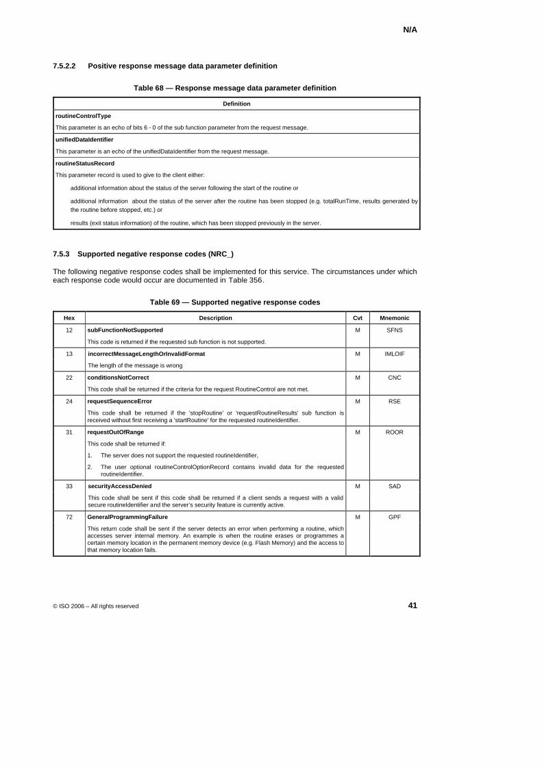
N/A
© ISO 2006 – All rights reserved 41
7.5.2.2 Positive response message data parameter definition
Table 68 — Response message data parameter definition
Definition
routineControlType
This parameter is an echo of bits 6 - 0 of the sub function parameter from the request message.
unifiedDataIdentifier
This parameter is an echo of the unifiedDataIdentifier from the request message.
routineStatusRecord
This parameter record is used to give to the client either:
additional information about the status of the server following the start of the routine or
additional information about the status of the server after the routine has been stopped (e.g. totalRunTime, results generated by the routine before stopped, etc.) or
results (exit status information) of the routine, which has been stopped previously in the server.
7.5.3 Supported negative response codes (NRC_)
The following negative response codes shall be implemented for this service. The circumstances under which each response code would occur are documented in XTable 356X.
Table 69 — Supported negative response codes
Hex Description Cvt Mnemonic
12 subFunctionNotSupported M SFNS
This code is returned if the requested sub function is not supported.
13 incorrectMessageLengthOrInvalidFormat M IMLOIF
The length of the message is wrong
22 conditionsNotCorrect M CNC
This code shall be returned if the criteria for the request RoutineControl are not met.
24 requestSequenceError M RSE
This code shall be returned if the 'stopRoutine' or 'requestRoutineResults' sub function is received without first receiving a 'startRoutine' for the requested routineIdentifier.
31 requestOutOfRange M ROOR
This code shall be returned if:
1. The server does not support the requested routineIdentifier,
2. The user optional routineControlOptionRecord contains invalid data for the requested routineIdentifier.
33 securityAccessDenied M SAD
This code shall be sent if this code shall be returned if a client sends a request with a valid secure routineIdentifier and the server’s security feature is currently active.
72 GeneralProgrammingFailure M GPF
This return code shall be sent if the server detects an error when performing a routine, which accesses server internal memory. An example is when the routine erases or programmes a certain memory location in the permanent memory device (e.g. Flash Memory) and the access to that memory location fails.

N/A
42 © ISO 2006 – All rights reserved
7.5.4 Message flow example(s) RoutineControl
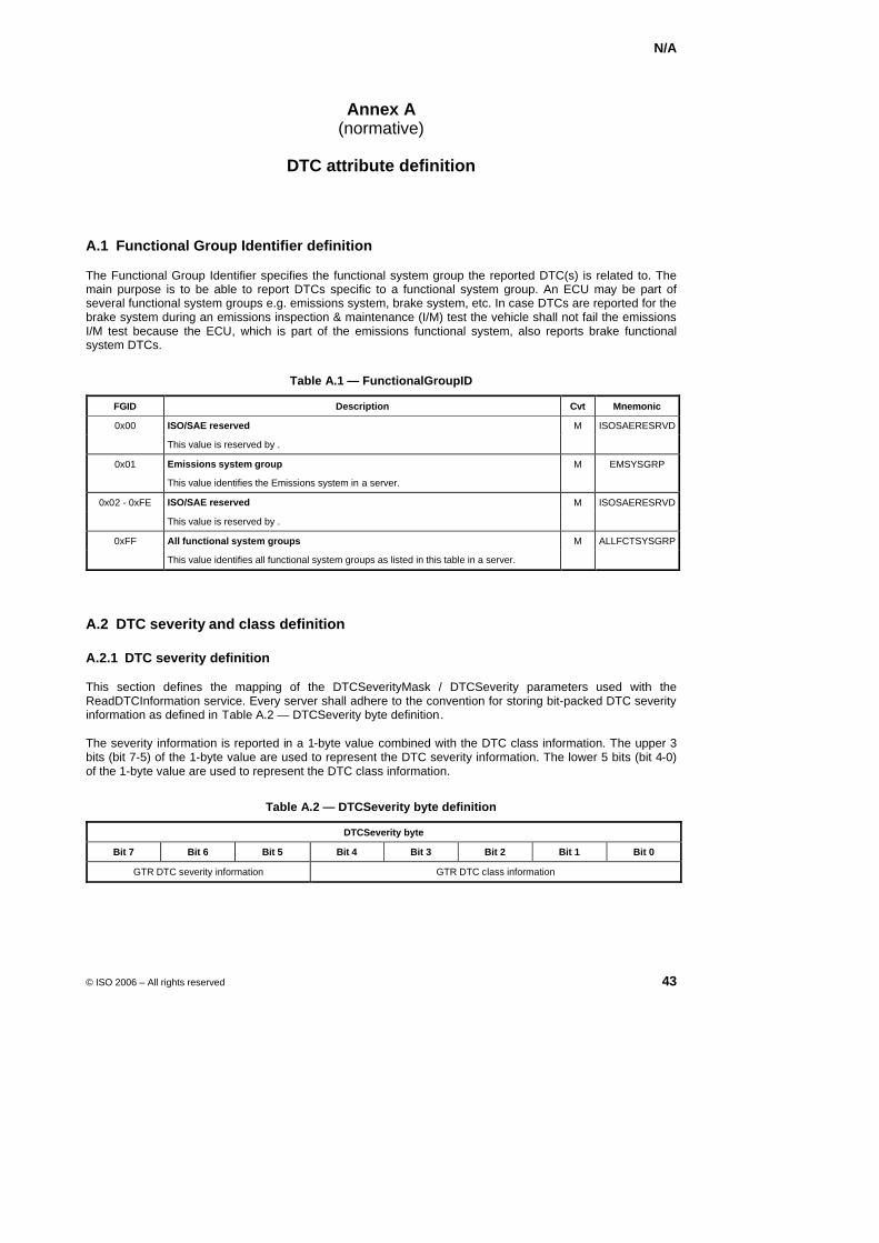
N/A
© ISO 2006 – All rights reserved 43
Annex A (normative)
DTC attribute definition
A.1 Functional Group Identifier definition
The Functional Group Identifier specifies the functional system group the reported DTC(s) is related to. The main purpose is to be able to report DTCs specific to a functional system group. An ECU may be part of several functional system groups e.g. emissions system, brake system, etc. In case DTCs are reported for the brake system during an emissions inspection & maintenance (I/M) test the vehicle shall not fail the emissions I/M test because the ECU, which is part of the emissions functional system, also reports brake functional system DTCs.
Table A.1 — FunctionalGroupID
FGID Description Cvt Mnemonic
0x00 ISO/SAE reserved M ISOSAERESRVD
This value is reserved by .
0x01 Emissions system group M EMSYSGRP
This value identifies the Emissions system in a server.
0x02 - 0xFE ISO/SAE reserved M ISOSAERESRVD
This value is reserved by .
0xFF All functional system groups M ALLFCTSYSGRP
This value identifies all functional system groups as listed in this table in a server.
A.2 DTC severity and class definition
A.2.1 DTC severity definition
This section defines the mapping of the DTCSeverityMask / DTCSeverity parameters used with the ReadDTCInformation service. Every server shall adhere to the convention for storing bit-packed DTC severity information as defined in XTable A.2 — DTCSeverity byte definitionX.
The severity information is reported in a 1-byte value combined with the DTC class information. The upper 3 bits (bit 7-5) of the 1-byte value are used to represent the DTC severity information. The lower 5 bits (bit 4-0) of the 1-byte value are used to represent the DTC class information.
Table A.2 — DTCSeverity byte definition
DTCSeverity byte
Bit 7 Bit 6 Bit 5 Bit 4 Bit 3 Bit 2 Bit 1 Bit 0
GTR DTC severity information GTR DTC class information
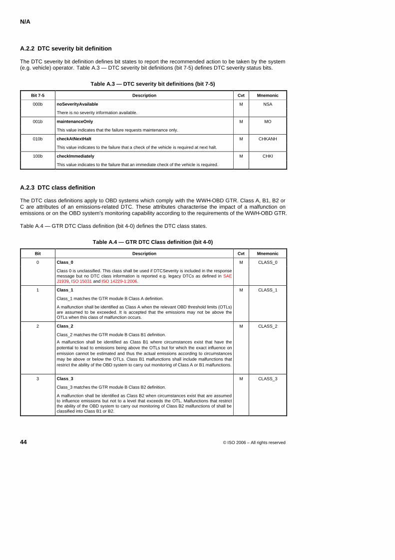
N/A
44 © ISO 2006 – All rights reserved
A.2.2 DTC severity bit definition
The DTC severity bit definition defines bit states to report the recommended action to be taken by the system (e.g. vehicle) operator. XTable A.3 — DTC severity bit definitions (bit 7-5) defines DTC severity status bits.X
Table A.3 — DTC severity bit definitions (bit 7-5)
Bit 7-5 Description Cvt Mnemonic
000b noSeverityAvailable M NSA
There is no severity information available.
001b maintenanceOnly M MO
This value indicates that the failure requests maintenance only.
010b checkAtNextHalt M CHKANH
This value indicates to the failure that a check of the vehicle is required at next halt.
100b checkImmediately M CHKI
This value indicates to the failure that an immediate check of the vehicle is required.
A.2.3 DTC class definition
The DTC class definitions apply to OBD systems which comply with the WWH-OBD GTR. Class A, B1, B2 or C are attributes of an emissions-related DTC. These attributes characterise the impact of a malfunction on emissions or on the OBD system's monitoring capability according to the requirements of the WWH-OBD GTR.
Table A.4 — GTR DTC Class definition (bit 4-0) defines the DTC class states.
Table A.4 — GTR DTC Class definition (bit 4-0)
Bit Description Cvt Mnemonic
0 Class_0 M CLASS_0
Class 0 is unclassified. This class shall be used if DTCSeverity is included in the response message but no DTC class information is reported e.g. legacy DTCs as defined in SAE J1939, ISO 15031 and ISO 14229-1:2006.
1 Class_1 M CLASS_1
Class_1 matches the GTR module B Class A definition.
A malfunction shall be identified as Class A when the relevant OBD threshold limits (OTLs) are assumed to be exceeded. It is accepted that the emissions may not be above the OTLs when this class of malfunction occurs.
2 Class_2 M CLASS_2
Class_2 matches the GTR module B Class B1 definition.
A malfunction shall be identified as Class B1 where circumstances exist that have the potential to lead to emissions being above the OTLs but for which the exact influence on emission cannot be estimated and thus the actual emissions according to circumstances may be above or below the OTLs. Class B1 malfunctions shall include malfunctions that restrict the ability of the OBD system to carry out monitoring of Class A or B1 malfunctions.
3 Class_3 M CLASS_3
Class_3 matches the GTR module B Class B2 definition.
A malfunction shall be identified as Class B2 when circumstances exist that are assumed to influence emissions but not to a level that exceeds the OTL. Malfunctions that restrict the ability of the OBD system to carry out monitoring of Class B2 malfunctions of shall be classified into Class B1 or B2.
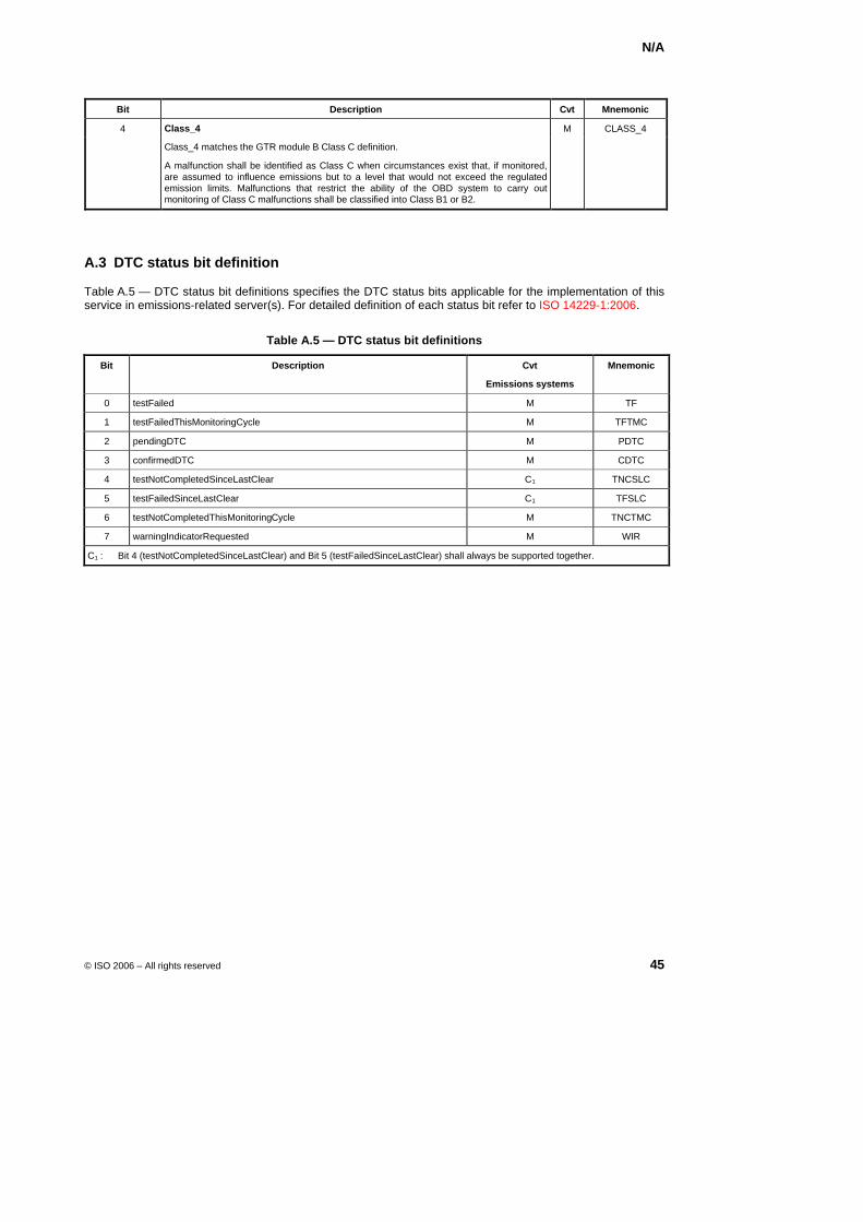
N/A
© ISO 2006 – All rights reserved 45
Bit Description Cvt Mnemonic
4 Class_4 M CLASS_4
Class_4 matches the GTR module B Class C definition.
A malfunction shall be identified as Class C when circumstances exist that, if monitored, are assumed to influence emissions but to a level that would not exceed the regulated emission limits. Malfunctions that restrict the ability of the OBD system to carry out monitoring of Class C malfunctions shall be classified into Class B1 or B2.
A.3 DTC status bit definition
Table A.5 — DTC status bit definitions specifies the DTC status bits applicable for the implementation of this service in emissions-related server(s). For detailed definition of each status bit refer to ISO 14229-1:2006.
Table A.5 — DTC status bit definitions
Bit Description Cvt Mnemonic
Emissions systems
0 testFailed M TF
1 testFailedThisMonitoringCycle M TFTMC
2 pendingDTC M PDTC
3 confirmedDTC M CDTC
4 testNotCompletedSinceLastClear C1 TNCSLC
5 testFailedSinceLastClear C1 TFSLC
6 testNotCompletedThisMonitoringCycle M TNCTMC
7 warningIndicatorRequested M WIR
C1 : Bit 4 (testNotCompletedSinceLastClear) and Bit 5 (testFailedSinceLastClear) shall always be supported together.
© ISO 2006 – All rights reserved
Document type: Publicly Available Specification Document subtype: Document stage: (20) Preparatory Document language: E
ISO TC 22/SC 3 N Date: N 2006-05-23
ISO/PDPAS 27145-4.5
ISO TC 22/SC 3/WG 1
Secretariat: DIN
Road vehicles — Implementation of WWH-OBD communication requirements — Part 4: Connection between vehicle and test equipment
Élément introductif — Élément central — Partie 4: Titre de la partie
Warning
This document is not an ISO International Standard. It is distributed for review and comment. It is subject to change without notice and may not be referred to as an International Standard.
Recipients of this draft are invited to submit, with their comments, notification of any relevant patent rights of which they are aware and to provide supporting documentation.
ISO/PDPAS 27145-4.5
ii © ISO 2006 – All rights reserved
Copyright notice
This ISO document is a working draft or committee draft and is copyright-protected by ISO. While the reproduction of working drafts or committee drafts in any form for use by participants in the ISO standards development process is permitted without prior permission from ISO, neither this document nor any extract from it may be reproduced, stored or transmitted in any form for any other purpose without prior written permission from ISO.
Requests for permission to reproduce this document for the purpose of selling it should be addressed as shown below or to ISO's member body in the country of the requester:
[Indicate the full address, telephone number, fax number, telex number, and electronic mail address, as appropriate, of the Copyright Manger of the ISO member body responsible for the secretariat of the TC or SC within the framework of which the working document has been prepared.]
Reproduction for sales purposes may be subject to royalty payments or a licensing agreement.
Violators may be prosecuted.
ISO/PDPAS 27145-4.5
© ISO 2006 – All rights reserved iii
Contents Page
Foreword ............................................................................................................................................................ iv Introduction.........................................................................................................................................................v 1 Scope ......................................................................................................................................................1 2 Normative references............................................................................................................................2 3 Terms and definitions ...........................................................................................................................3 4 Symbols and abbreviated terms ..........................................................................................................3 5 Conventions...........................................................................................................................................4 6 Vehicle and external test equipment connection requirements.......................................................5 6.1 Overview.................................................................................................................................................5 7 CAN based wired connection...............................................................................................................5 7.1 Diagnostic connector............................................................................................................................5 7.2 Initialization sequence ..........................................................................................................................5 7.2.1 External test equipment error detection provisions..........................................................................7 7.2.2 11 bit CAN identifier verification procedure .......................................................................................8 7.2.3 29 bit CAN identifier verification procedure .....................................................................................11 7.3 Application layer..................................................................................................................................14 7.3.1 General .................................................................................................................................................14 7.3.2 Application layer timing parameters .................................................................................................15 7.4 Presentation layer ...............................................................................................................................16 7.4.1 Communication and addressing types .............................................................................................17 7.4.2 Diagnostic protocol timing parameters ............................................................................................17 7.5 Session layer .......................................................................................................................................19 7.6 Network layer .......................................................................................................................................19 7.6.1 Addressing formats.............................................................................................................................19 7.6.2 Data link layer interface ......................................................................................................................19 7.6.3 Maximum number of WWH-OBD ECUs.............................................................................................22 7.6.4 Functional addressing ........................................................................................................................22 7.6.5 Physical addressing............................................................................................................................23 7.6.6 Network layer timing parameter values ............................................................................................24 7.6.7 Definition of network layer parameter values...................................................................................24 7.7 Data link layer ......................................................................................................................................25 7.8 Physical layer.......................................................................................................................................26 7.8.1 External test equipment baudrates ...................................................................................................26 7.8.2 External test equipment CAN bit timing............................................................................................26 7.8.3 External test equipment......................................................................................................................28
ISO/PDPAS 27145-4.5
iv © ISO 2006 – All rights reserved
Foreword
ISO (the International Organization for Standardization) is a worldwide federation of national standards bodies (ISO member bodies). The work of preparing International Standards is normally carried out through ISO technical committees. Each member body interested in a subject for which a technical committee has been established has the right to be represented on that committee. International organizations, governmental and non-governmental, in liaison with ISO, also take part in the work. ISO collaborates closely with the International Electrotechnical Commission (IEC) on all matters of electrotechnical standardization.
International Standards are drafted in accordance with the rules given in the ISO/IEC Directives, Part 2.
The main task of technical committees is to prepare International Standards. Draft International Standards adopted by the technical committees are circulated to the member bodies for voting. Publication as an International Standard requires approval by at least 75 % of the member bodies casting a vote.
In other circumstances, particularly when there is an urgent market requirement for such documents, a technical committee may decide to publish other types of normative document:
— an ISO Publicly Available Specification (ISO/PAS) represents an agreement between technical experts in an ISO working group and is accepted for publication if it is approved by more than 50 % of the members of the parent committee casting a vote;
— an ISO Technical Specification (ISO/TS) represents an agreement between the members of a technical committee and is accepted for publication if it is approved by 2/3 of the members of the committee casting a vote.
An ISO/PAS or ISO/TS is reviewed after three years in order to decide whether it will be confirmed for a further three years, revised to become an International Standard, or withdrawn. If the ISO/PAS or ISO/TS is confirmed, it is reviewed again after a further three years, at which time it must either be transformed into an International Standard or be withdrawn.
Attention is drawn to the possibility that some of the elements of this document may be the subject of patent rights. ISO shall not be held responsible for identifying any or all such patent rights.
ISO/PAS 27145-4 was prepared by Technical Committee ISO/TC 22, Road vehicles, Subcommittee SC 3, Electrical and electronic equipment.
ISO/PAS 27145 consists of the following parts, under the general title Road vehicles — Implementation of WWH-OBD communication requirements:
Part 1: General information and use case definition
Part 2: Common emissions-related data dictionary
Part 3: Common message dictionary
Part 4: Connection between vehicle and test equipment
Part 5: External test equipment
NOTE Part 4 of the standard will be extended as necessary upon introduction of additional communication media as noted in the scope of this document.
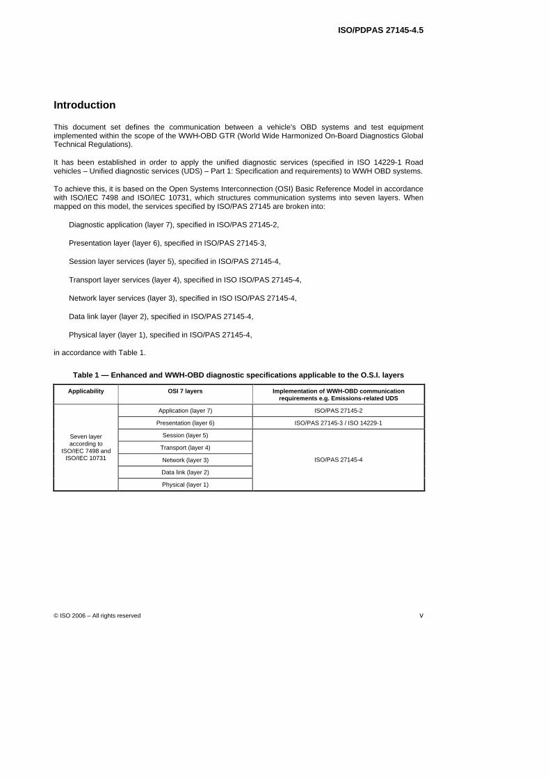
ISO/PDPAS 27145-4.5
© ISO 2006 – All rights reserved v
Introduction
This document set defines the communication between a vehicle's OBD systems and test equipment implemented within the scope of the WWH-OBD GTR (World Wide Harmonized On-Board Diagnostics Global Technical Regulations).
It has been established in order to apply the unified diagnostic services (specified in ISO 14229-1 Road vehicles – Unified diagnostic services (UDS) – Part 1: Specification and requirements) to WWH OBD systems.
To achieve this, it is based on the Open Systems Interconnection (OSI) Basic Reference Model in accordance with ISO/IEC 7498 and ISO/IEC 10731, which structures communication systems into seven layers. When mapped on this model, the services specified by ISO/PAS 27145 are broken into:
Diagnostic application (layer 7), specified in ISO/PAS 27145-2,
Presentation layer (layer 6), specified in ISO/PAS 27145-3,
Session layer services (layer 5), specified in ISO/PAS 27145-4,
Transport layer services (layer 4), specified in ISO ISO/PAS 27145-4,
Network layer services (layer 3), specified in ISO ISO/PAS 27145-4,
Data link layer (layer 2), specified in ISO/PAS 27145-4,
Physical layer (layer 1), specified in ISO/PAS 27145-4,
in accordance with Table 1.
Table 1 — Enhanced and WWH-OBD diagnostic specifications applicable to the O.S.I. layers
Applicability OSI 7 layers Implementation of WWH-OBD communication requirements e.g. Emissions-related UDS
Application (layer 7) ISO/PAS 27145-2
Presentation (layer 6) ISO/PAS 27145-3 / ISO 14229-1
Session (layer 5)
Transport (layer 4)
Network (layer 3)
Data link (layer 2)
Seven layer according to
ISO/IEC 7498 and ISO/IEC 10731
Physical (layer 1)
ISO/PAS 27145-4

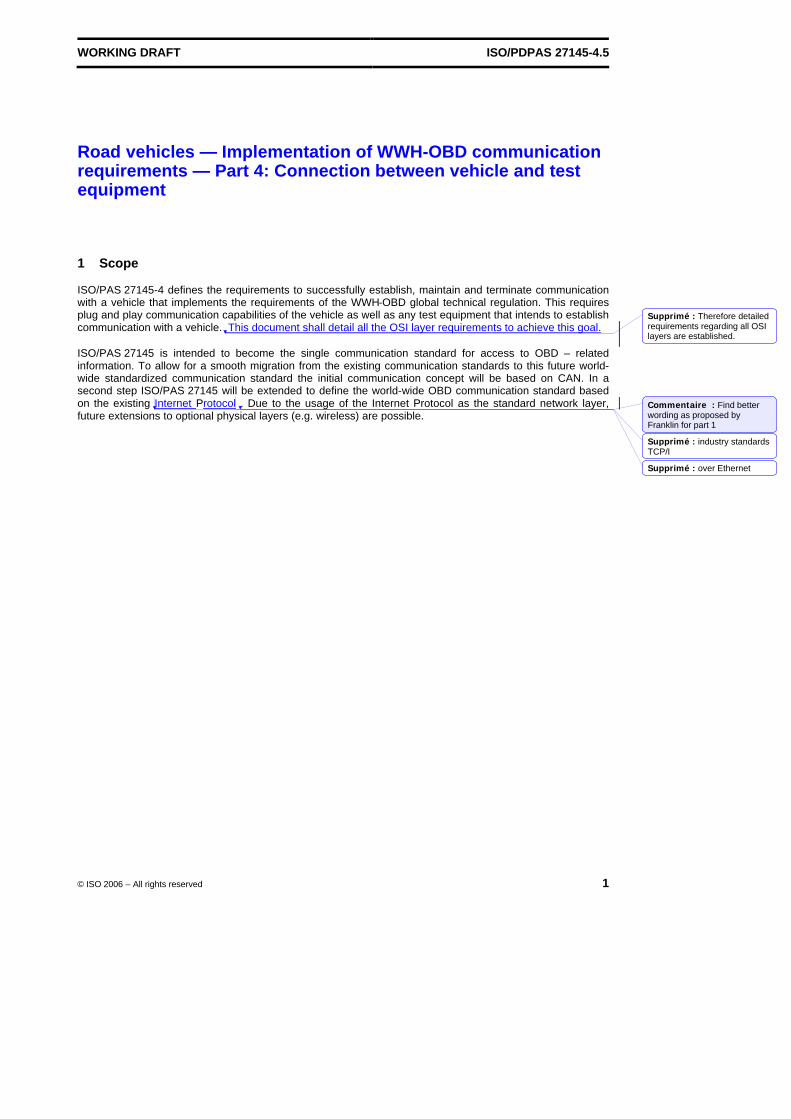
WORKING DRAFT ISO/PDPAS 27145-4.5
© ISO 2006 – All rights reserved 1
Road vehicles — Implementation of WWH-OBD communication requirements — Part 4: Connection between vehicle and test equipment
1 Scope
ISO/PAS 27145-4 defines the requirements to successfully establish, maintain and terminate communication with a vehicle that implements the requirements of the WWH-OBD global technical regulation. This requires plug and play communication capabilities of the vehicle as well as any test equipment that intends to establish communication with a vehicle. This document shall detail all the OSI layer requirements to achieve this goal.
ISO/PAS 27145 is intended to become the single communication standard for access to OBD – related information. To allow for a smooth migration from the existing communication standards to this future world-wide standardized communication standard the initial communication concept will be based on CAN. In a second step ISO/PAS 27145 will be extended to define the world-wide OBD communication standard based on the existing Internet Protocol . Due to the usage of the Internet Protocol as the standard network layer, future extensions to optional physical layers (e.g. wireless) are possible.
Supprimé : Therefore detailed requirements regarding all OSI layers are established.
Commentaire : Find better wording as proposed by Franklin for part 1
Supprimé : industry standards TCP/I
Supprimé : over Ethernet
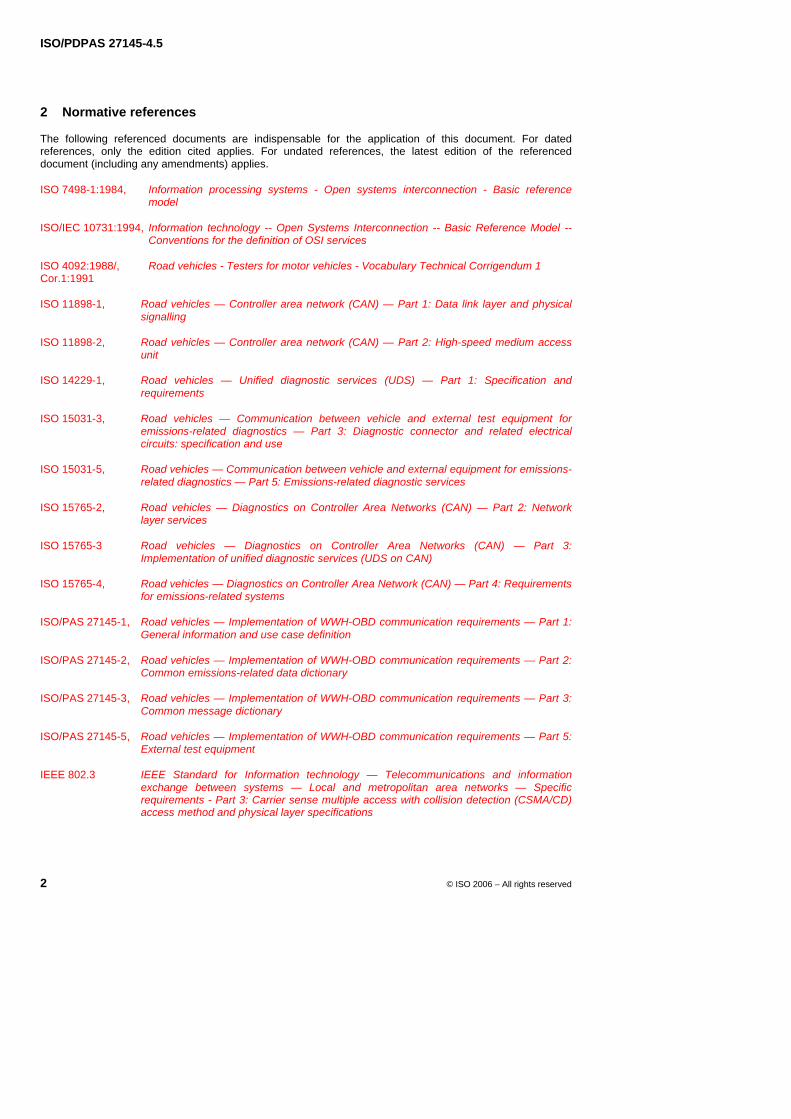
ISO/PDPAS 27145-4.5
2 © ISO 2006 – All rights reserved
2 Normative references
The following referenced documents are indispensable for the application of this document. For dated references, only the edition cited applies. For undated references, the latest edition of the referenced document (including any amendments) applies.
ISO 7498-1:1984, Information processing systems - Open systems interconnection - Basic reference model
ISO/IEC 10731:1994, Information technology -- Open Systems Interconnection -- Basic Reference Model -- Conventions for the definition of OSI services
ISO 4092:1988/, Road vehicles - Testers for motor vehicles - Vocabulary Technical Corrigendum 1 Cor.1:1991
ISO 11898-1, Road vehicles — Controller area network (CAN) — Part 1: Data link layer and physical signalling
ISO 11898-2, Road vehicles — Controller area network (CAN) — Part 2: High-speed medium access unit
ISO 14229-1, Road vehicles — Unified diagnostic services (UDS) — Part 1: Specification and requirements
ISO 15031-3, Road vehicles — Communication between vehicle and external test equipment for emissions-related diagnostics — Part 3: Diagnostic connector and related electrical circuits: specification and use
ISO 15031-5, Road vehicles — Communication between vehicle and external equipment for emissions-related diagnostics — Part 5: Emissions-related diagnostic services
ISO 15765-2, Road vehicles — Diagnostics on Controller Area Networks (CAN) — Part 2: Network layer services
ISO 15765-3 Road vehicles — Diagnostics on Controller Area Networks (CAN) — Part 3: Implementation of unified diagnostic services (UDS on CAN)
ISO 15765-4, Road vehicles — Diagnostics on Controller Area Network (CAN) — Part 4: Requirements for emissions-related systems
ISO/PAS 27145-1, Road vehicles — Implementation of WWH-OBD communication requirements — Part 1: General information and use case definition
ISO/PAS 27145-2, Road vehicles — Implementation of WWH-OBD communication requirements — Part 2: Common emissions-related data dictionary
ISO/PAS 27145-3, Road vehicles — Implementation of WWH-OBD communication requirements — Part 3: Common message dictionary
ISO/PAS 27145-5, Road vehicles — Implementation of WWH-OBD communication requirements — Part 5: External test equipment
IEEE 802.3 IEEE Standard for Information technology — Telecommunications and information exchange between systems — Local and metropolitan area networks — Specific requirements - Part 3: Carrier sense multiple access with collision detection (CSMA/CD) access method and physical layer specifications
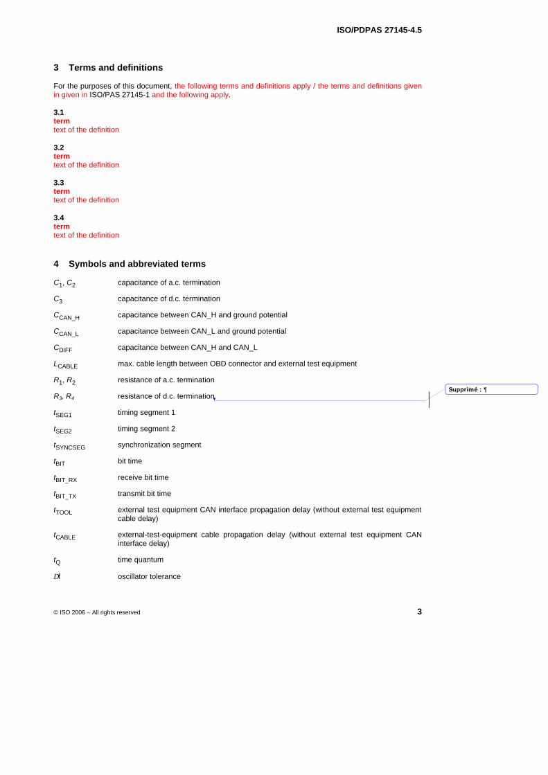
ISO/PDPAS 27145-4.5
© ISO 2006 – All rights reserved 3
3 Terms and definitions
For the purposes of this document, the following terms and definitions apply / the terms and definitions given in given in ISO/PAS 27145-1 and the following apply.
3.1 term text of the definition
3.2 term text of the definition
3.3 term text of the definition
3.4 term text of the definition
4 Symbols and abbreviated terms
C1, C2 capacitance of a.c. termination
C3 capacitance of d.c. termination
CCAN_H capacitance between CAN_H and ground potential
CCAN_L capacitance between CAN_L and ground potential
CDIFF capacitance between CAN_H and CAN_L
LCABLE max. cable length between OBD connector and external test equipment
R1, R2 resistance of a.c. termination
R3, R4 resistance of d.c. termination
tSEG1 timing segment 1
tSEG2 timing segment 2
tSYNCSEG synchronization segment
tBIT bit time
tBIT_RX receive bit time
tBIT_TX transmit bit time
tTOOL external test equipment CAN interface propagation delay (without external test equipment cable delay)
tCABLE external-test-equipment cable propagation delay (without external test equipment CAN interface delay)
tQ time quantum
∆f oscillator tolerance
Supprimé : 
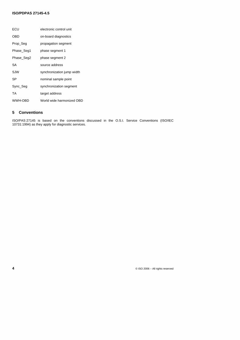
ISO/PDPAS 27145-4.5
4 © ISO 2006 – All rights reserved
ECU electronic control unit
OBD on-board diagnostics
Prop_Seg propagation segment
Phase_Seg1 phase segment 1
Phase_Seg2 phase segment 2
SA source address
SJW synchronization jump width
SP nominal sample point
Sync_Seg synchronization segment
TA target address
WWH-OBD World wide harmonized OBD
5 Conventions
ISO/PAS 27145 is based on the conventions discussed in the O.S.I. Service Conventions (ISO/IEC 10731:1994) as they apply for diagnostic services.
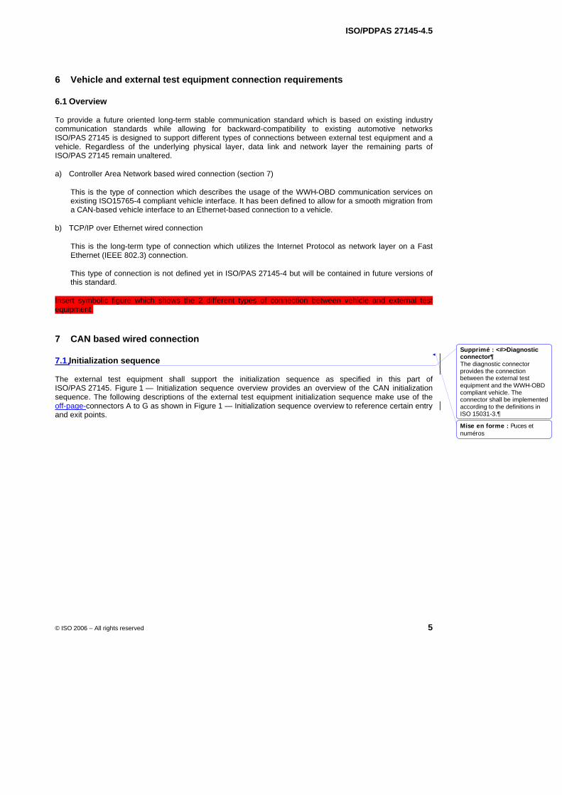
ISO/PDPAS 27145-4.5
© ISO 2006 – All rights reserved 5
6 Vehicle and external test equipment connection requirements
6.1 Overview
To provide a future oriented long-term stable communication standard which is based on existing industry communication standards while allowing for backward-compatibility to existing automotive networks ISO/PAS 27145 is designed to support different types of connections between external test equipment and a vehicle. Regardless of the underlying physical layer, data link and network layer the remaining parts of ISO/PAS 27145 remain unaltered.
a) Controller Area Network based wired connection (section 7)
This is the type of connection which describes the usage of the WWH-OBD communication services on existing ISO15765-4 compliant vehicle interface. It has been defined to allow for a smooth migration from a CAN-based vehicle interface to an Ethernet-based connection to a vehicle.
b) TCP/IP over Ethernet wired connection
This is the long-term type of connection which utilizes the Internet Protocol as network layer on a Fast Ethernet (IEEE 802.3) connection.
This type of connection is not defined yet in ISO/PAS 27145-4 but will be contained in future versions of this standard.
Insert symbolic figure which shows the 2 different types of connection between vehicle and external test equipment.
7 CAN based wired connection
7.1 Initialization sequence
The external test equipment shall support the initialization sequence as specified in this part of ISO/PAS 27145. Figure 1 — Initialization sequence overview provides an overview of the CAN initialization sequence. The following descriptions of the external test equipment initialization sequence make use of the off-page-connectors A to G as shown in Figure 1 — Initialization sequence overview to reference certain entry and exit points.
Mise en forme : Puces etnuméros
Supprimé : <#>Diagnostic connector¶The diagnostic connector provides the connection between the external test equipment and the WWH-OBD compliant vehicle. The connector shall be implemented according to the definitions in ISO 15031-3.
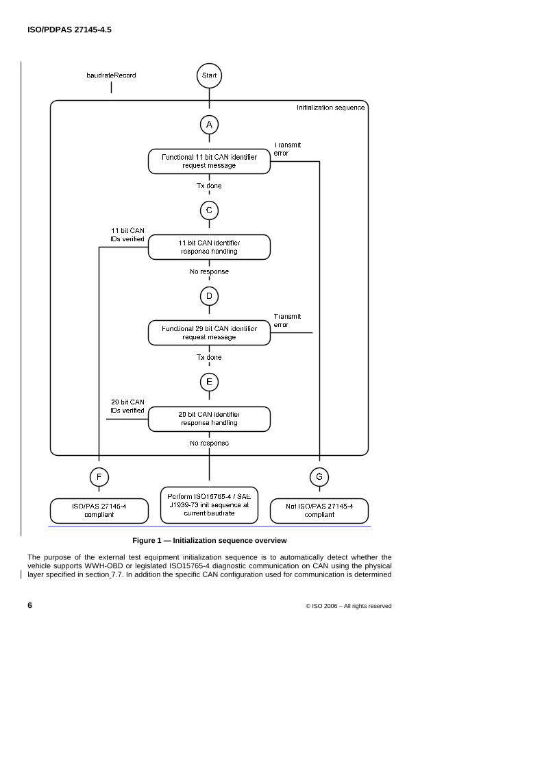
ISO/PDPAS 27145-4.5
6 © ISO 2006 – All rights reserved
Figure 1 — Initialization sequence overview
The purpose of the external test equipment initialization sequence is to automatically detect whether the vehicle supports WWH-OBD or legislated ISO15765-4 diagnostic communication on CAN using the physical layer specified in section 7.7. In addition the specific CAN configuration used for communication is determined
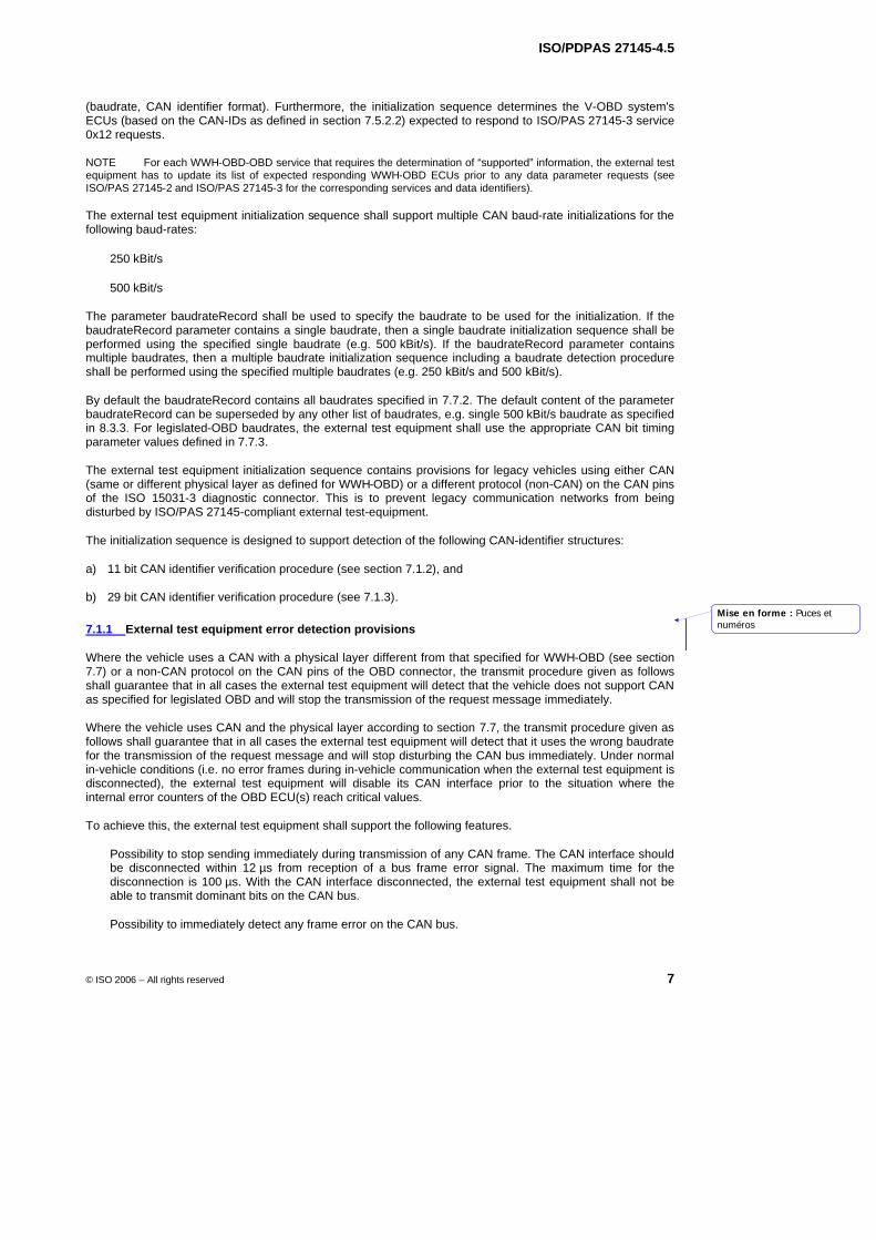
ISO/PDPAS 27145-4.5
© ISO 2006 – All rights reserved 7
(baudrate, CAN identifier format). Furthermore, the initialization sequence determines the V-OBD system's ECUs (based on the CAN-IDs as defined in section 7.5.2.2) expected to respond to ISO/PAS 27145-3 service 0x12 requests.
NOTE For each WWH-OBD-OBD service that requires the determination of “supported” information, the external test equipment has to update its list of expected responding WWH-OBD ECUs prior to any data parameter requests (see ISO/PAS 27145-2 and ISO/PAS 27145-3 for the corresponding services and data identifiers).
The external test equipment initialization sequence shall support multiple CAN baud-rate initializations for the following baud-rates:
250 kBit/s
500 kBit/s
The parameter baudrateRecord shall be used to specify the baudrate to be used for the initialization. If the baudrateRecord parameter contains a single baudrate, then a single baudrate initialization sequence shall be performed using the specified single baudrate (e.g. 500 kBit/s). If the baudrateRecord parameter contains multiple baudrates, then a multiple baudrate initialization sequence including a baudrate detection procedure shall be performed using the specified multiple baudrates (e.g. 250 kBit/s and 500 kBit/s).
By default the baudrateRecord contains all baudrates specified in 7.7.2. The default content of the parameter baudrateRecord can be superseded by any other list of baudrates, e.g. single 500 kBit/s baudrate as specified in 8.3.3. For legislated-OBD baudrates, the external test equipment shall use the appropriate CAN bit timing parameter values defined in 7.7.3.
The external test equipment initialization sequence contains provisions for legacy vehicles using either CAN (same or different physical layer as defined for WWH-OBD) or a different protocol (non-CAN) on the CAN pins of the ISO 15031-3 diagnostic connector. This is to prevent legacy communication networks from being disturbed by ISO/PAS 27145-compliant external test-equipment.
The initialization sequence is designed to support detection of the following CAN-identifier structures:
a) 11 bit CAN identifier verification procedure (see section 7.1.2), and
b) 29 bit CAN identifier verification procedure (see 7.1.3).
7.1.1 External test equipment error detection provisions
Where the vehicle uses a CAN with a physical layer different from that specified for WWH-OBD (see section 7.7) or a non-CAN protocol on the CAN pins of the OBD connector, the transmit procedure given as follows shall guarantee that in all cases the external test equipment will detect that the vehicle does not support CAN as specified for legislated OBD and will stop the transmission of the request message immediately.
Where the vehicle uses CAN and the physical layer according to section 7.7, the transmit procedure given as follows shall guarantee that in all cases the external test equipment will detect that it uses the wrong baudrate for the transmission of the request message and will stop disturbing the CAN bus immediately. Under normal in-vehicle conditions (i.e. no error frames during in-vehicle communication when the external test equipment is disconnected), the external test equipment will disable its CAN interface prior to the situation where the internal error counters of the OBD ECU(s) reach critical values.
To achieve this, the external test equipment shall support the following features.
Possibility to stop sending immediately during transmission of any CAN frame. The CAN interface should be disconnected within 12 µs from reception of a bus frame error signal. The maximum time for the disconnection is 100 µs. With the CAN interface disconnected, the external test equipment shall not be able to transmit dominant bits on the CAN bus.
Possibility to immediately detect any frame error on the CAN bus.
Mise en forme : Puces etnuméros
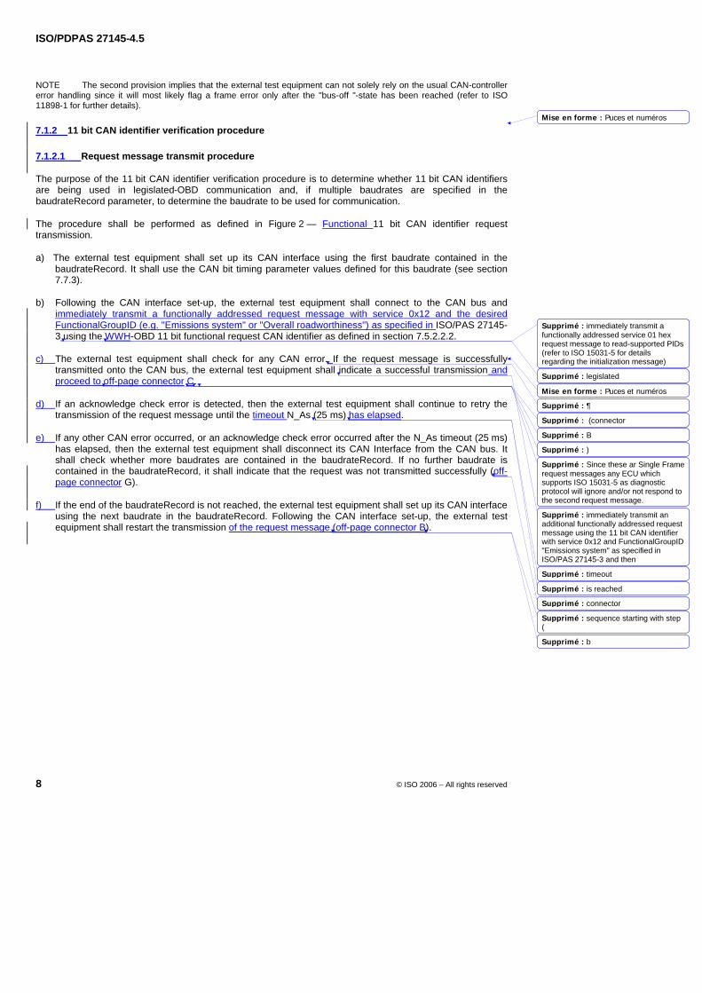
ISO/PDPAS 27145-4.5
8 © ISO 2006 – All rights reserved
NOTE The second provision implies that the external test equipment can not solely rely on the usual CAN-controller error handling since it will most likely flag a frame error only after the "bus-off "-state has been reached (refer to ISO 11898-1 for further details).
7.1.2 11 bit CAN identifier verification procedure
7.1.2.1 Request message transmit procedure
The purpose of the 11 bit CAN identifier verification procedure is to determine whether 11 bit CAN identifiers are being used in legislated-OBD communication and, if multiple baudrates are specified in the baudrateRecord parameter, to determine the baudrate to be used for communication.
The procedure shall be performed as defined in Figure 2 — Functional 11 bit CAN identifier request transmission.
a) The external test equipment shall set up its CAN interface using the first baudrate contained in the baudrateRecord. It shall use the CAN bit timing parameter values defined for this baudrate (see section 7.7.3).
b) Following the CAN interface set-up, the external test equipment shall connect to the CAN bus and immediately transmit a functionally addressed request message with service 0x12 and the desired FunctionalGroupID (e.g. "Emissions system" or "Overall roadworthiness") as specified in ISO/PAS 27145-3 using the WWH-OBD 11 bit functional request CAN identifier as defined in section 7.5.2.2.2.
c) The external test equipment shall check for any CAN error. If the request message is successfully transmitted onto the CAN bus, the external test equipment shall indicate a successful transmission and proceed to off-page connector C.
d) If an acknowledge check error is detected, then the external test equipment shall continue to retry the transmission of the request message until the timeout N_As (25 ms) has elapsed.
e) If any other CAN error occurred, or an acknowledge check error occurred after the N_As timeout (25 ms) has elapsed, then the external test equipment shall disconnect its CAN Interface from the CAN bus. It shall check whether more baudrates are contained in the baudrateRecord. If no further baudrate is contained in the baudrateRecord, it shall indicate that the request was not transmitted successfully (off-page connector G).
f) If the end of the baudrateRecord is not reached, the external test equipment shall set up its CAN interface using the next baudrate in the baudrateRecord. Following the CAN interface set-up, the external test equipment shall restart the transmission of the request message (off-page connector B).
Mise en forme : Puces et numéros
Mise en forme : Puces et numéros
Supprimé : immediately transmit a functionally addressed service 01 hex request message to read-supported PIDs (refer to ISO 15031-5 for details regarding the initialization message)
Supprimé : legislated
Supprimé : 
Supprimé : (connector
Supprimé : B
Supprimé : )
Supprimé : Since these ar Single Frame request messages any ECU which supports ISO 15031-5 as diagnostic protocol will ignore and/or not respond to the second request message.
Supprimé : immediately transmit an additional functionally addressed request message using the 11 bit CAN identifier with service 0x12 and FunctionalGroupID "Emissions system" as specified in ISO/PAS 27145-3 and then
Supprimé : timeout
Supprimé : is reached
Supprimé : connector
Supprimé : sequence starting with step (
Supprimé : b
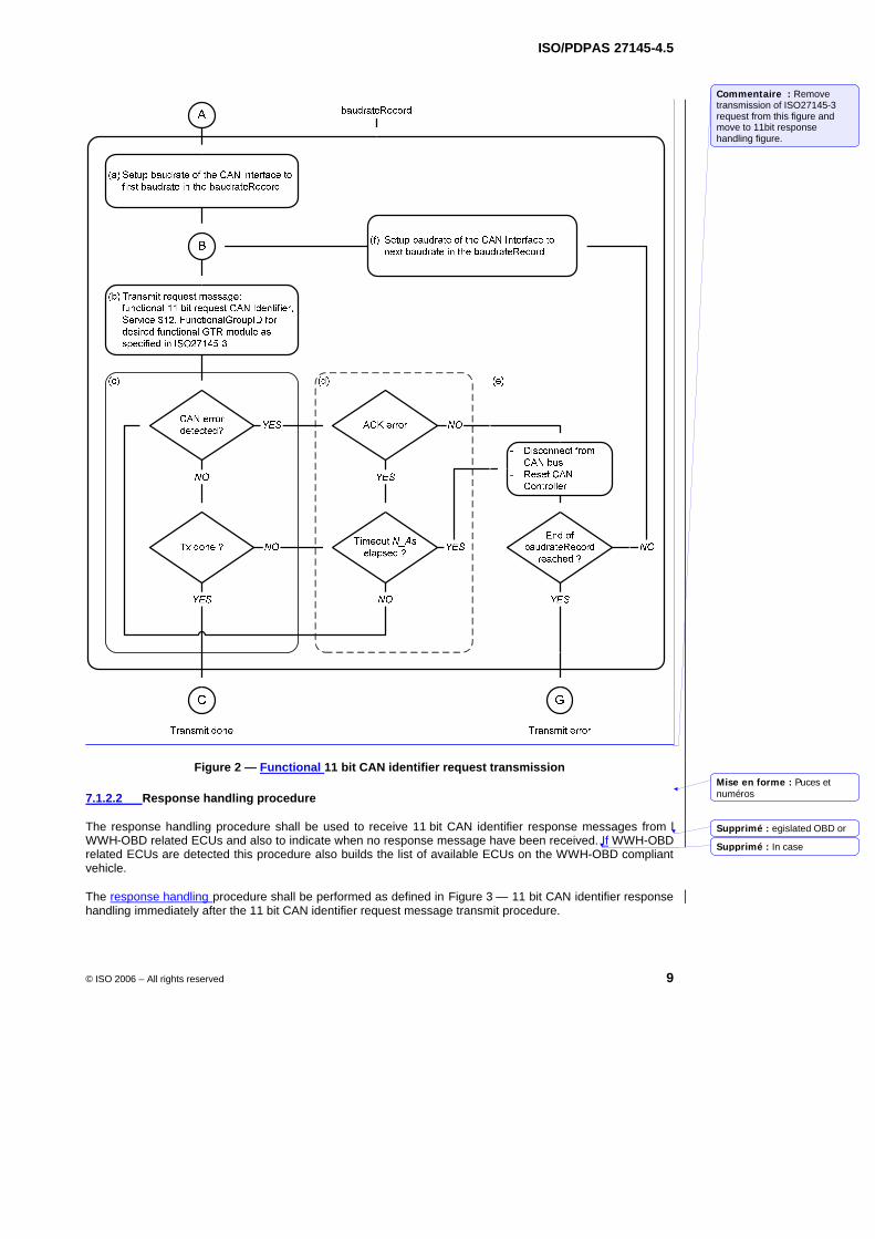
ISO/PDPAS 27145-4.5
© ISO 2006 – All rights reserved 9
Figure 2 — Functional 11 bit CAN identifier request transmission
7.1.2.2 Response handling procedure
The response handling procedure shall be used to receive 11 bit CAN identifier response messages from l WWH-OBD related ECUs and also to indicate when no response message have been received. If WWH-OBD related ECUs are detected this procedure also builds the list of available ECUs on the WWH-OBD compliant vehicle.
The response handling procedure shall be performed as defined in Figure 3 — 11 bit CAN identifier response handling immediately after the 11 bit CAN identifier request message transmit procedure.
Mise en forme : Puces etnuméros
Commentaire : Remove transmission of ISO27145-3 request from this figure and move to 11bit response handling figure.
Supprimé : egislated OBD or
Supprimé : In case
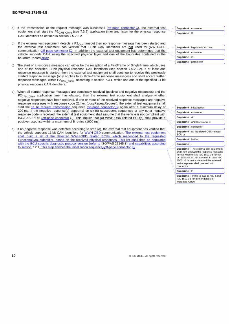
ISO/PDPAS 27145-4.5
10 © ISO 2006 – All rights reserved
a) If the transmission of the request message was successful (off-page connector C), the external test equipment shall start the P2CAN_Client (see 7.3.2) application timer and listen for the physical response CAN identifiers as defined in section 7.5.2.2.2.
b) If the external test equipment detects a P2CAN timeout then no response message has been started and the external test equipment has verified that 11 bit CAN identifiers are not used for WWH-OBD communication (off-page connector D). In addition the external test equipment has determined that the vehicle supports CAN, using the specified physical layer and one of the baudrates contained in the baudrateRecord array.
c) The start of a response message can either be the reception of a FirstFrame or SingleFrame which uses one of the specified 11 bit physical response CAN identifiers (see section 7.5.2.2.2). If at least one response message is started, then the external test equipment shall continue to receive this previously started response message (only applies to multiple-frame response messages) and shall accept further response messages, within P2CAN_Client according to section 7.3.1, which use one of the specified 11 bit physical response CAN identifiers.
d) When all started response messages are completely received (positive and negative responses) and the P2CAN_Client application timer has elapsed, then the external test equipment shall analyse whether negative responses have been received. If one or more of the received response messages are negative response messages with response code 21 hex (busyRepeatRequest), the external test equipment shall start the 11 bit request transmission sequence (off-page connector B) again after a minimum delay of 200 ms. If the negative response(s) appear(s) on six (6) subsequent sequences or any other negative response code is received, the external test equipment shall assume that the vehicle is not compliant with ISO/PAS 27145 (off-page connector G). This implies that (a) WWH-OBD related ECU(s) shall provide a positive response within a maximum of 5 retries (1000 ms).
e) If no negative response was detected according to step (d), the external test equipment has verified that the vehicle supports 11 bit CAN identifiers for WWH-OBD communication. The external test equipment shall build a list of the detected WWH-OBD related ECUs, which responded to the requested FunctionalGroupIdentifier, based on the received physical responses. This list shall then be populated with the ECU specific diagnostic protocol version (refer to ISO/PAS 27145-3) and capabilities according to section 7.2.1. This step finishes the initialization sequence (off-page connector F).
Supprimé : connector
Supprimé : B
Supprimé : legislated-OBD and
Supprimé : connector
Supprimé : C
Supprimé : parameter
Supprimé : initialization
Supprimé : connector
Supprimé : A
Supprimé : and ISO 15765-4
Supprimé : connector
Supprimé : (a) legislated OBD-related ECU or
Supprimé : further
Supprimé : .
Supprimé : The external test equipment shall now analyze the response message format whether it is ISO 15031-5 format or ISO/PAS 27145-3 format. In case ISO 15031-5 format is detected the external test equipment shall proceed with connector
Supprimé : E
Supprimé : (refer to ISO 15765-4 and ISO 15031-5 for further details for legislated-OBD)
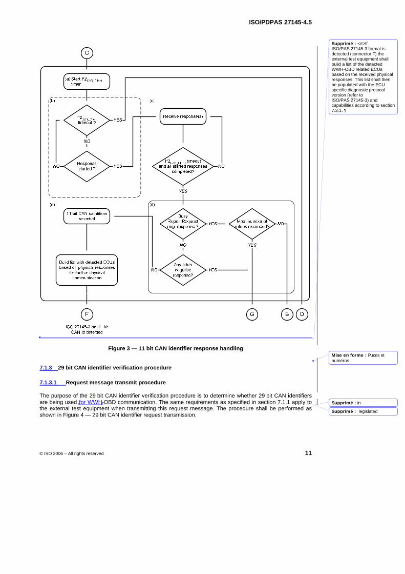
ISO/PDPAS 27145-4.5
© ISO 2006 – All rights reserved 11
Figure 3 — 11 bit CAN identifier response handling
7.1.3 29 bit CAN identifier verification procedure
7.1.3.1 Request message transmit procedure
The purpose of the 29 bit CAN identifier verification procedure is to determine whether 29 bit CAN identifiers are being used for WWH-OBD communication. The same requirements as specified in section 7.1.1 apply to the external test equipment when transmitting this request message. The procedure shall be performed as shown in Figure 4 — 29 bit CAN identifier request transmission.
Mise en forme : Puces etnuméros
Supprimé : <#>If ISO/PAS 27145-3 format is detected (connector F) the external test equipment shall build a list of the detected WWH-OBD related ECUs based on the received physical responses. This list shall then be populated with the ECU specific diagnostic protocol version (refer to ISO/PAS 27145-3) and capabilities according to section 7.3.1. 
Supprimé : in
Supprimé : legislated
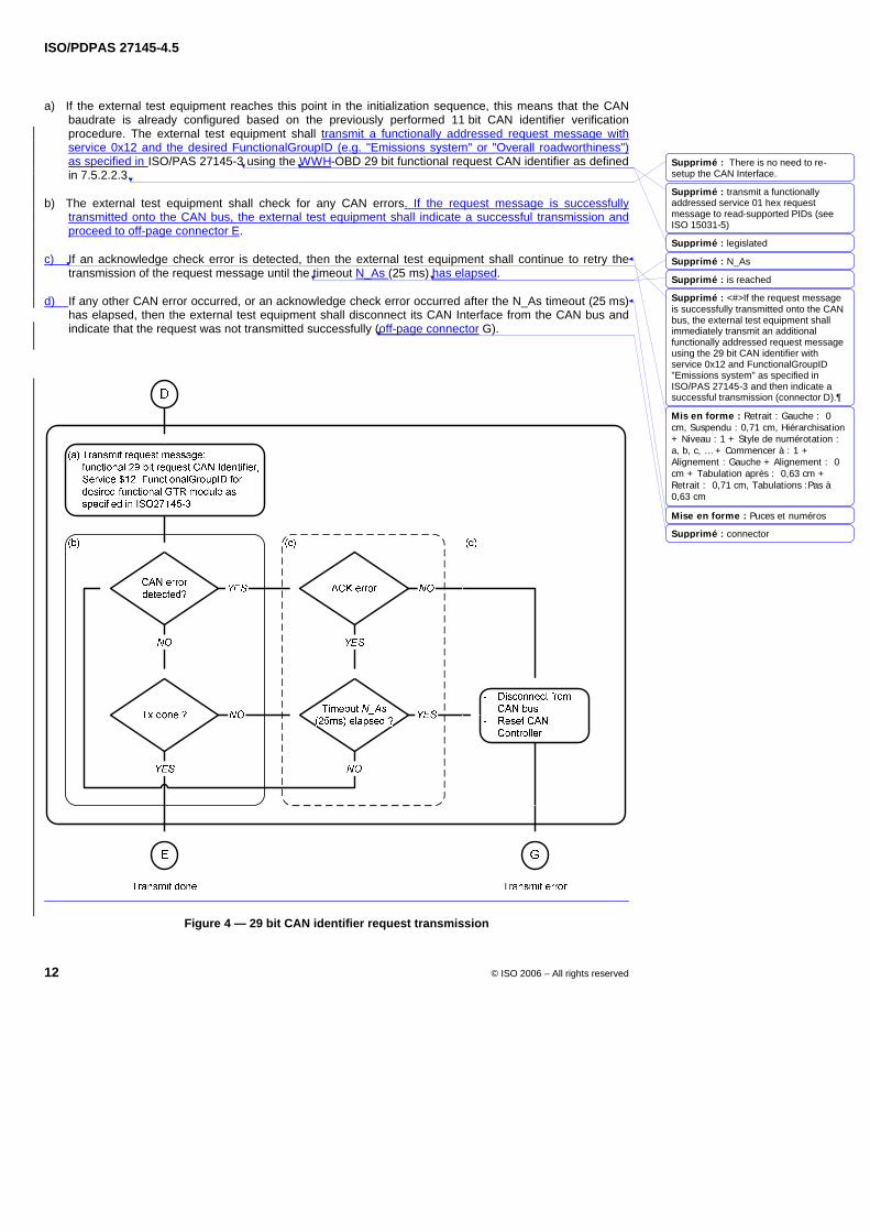
ISO/PDPAS 27145-4.5
12 © ISO 2006 – All rights reserved
a) If the external test equipment reaches this point in the initialization sequence, this means that the CAN baudrate is already configured based on the previously performed 11 bit CAN identifier verification procedure. The external test equipment shall transmit a functionally addressed request message with service 0x12 and the desired FunctionalGroupID (e.g. "Emissions system" or "Overall roadworthiness") as specified in ISO/PAS 27145-3 using the WWH-OBD 29 bit functional request CAN identifier as defined in 7.5.2.2.3.
b) The external test equipment shall check for any CAN errors. If the request message is successfully transmitted onto the CAN bus, the external test equipment shall indicate a successful transmission and proceed to off-page connector E.
c) If an acknowledge check error is detected, then the external test equipment shall continue to retry the transmission of the request message until the timeout N_As (25 ms) has elapsed.
d) If any other CAN error occurred, or an acknowledge check error occurred after the N_As timeout (25 ms) has elapsed, then the external test equipment shall disconnect its CAN Interface from the CAN bus and indicate that the request was not transmitted successfully (off-page connector G).
Figure 4 — 29 bit CAN identifier request transmission
Mis en forme : Retrait : Gauche : 0cm, Suspendu : 0,71 cm, Hiérarchisation+ Niveau : 1 + Style de numérotation :a, b, c, … + Commencer à : 1 +Alignement : Gauche + Alignement : 0cm + Tabulation après : 0,63 cm +Retrait : 0,71 cm, Tabulations :Pas à 0,63 cm
Mise en forme : Puces et numéros
Supprimé : There is no need to re-setup the CAN Interface.
Supprimé : transmit a functionally addressed service 01 hex request message to read-supported PIDs (see ISO 15031-5)
Supprimé : legislated
Supprimé : N_As
Supprimé : is reached
Supprimé : <#>If the request message is successfully transmitted onto the CAN bus, the external test equipment shall immediately transmit an additional functionally addressed request message using the 29 bit CAN identifier with service 0x12 and FunctionalGroupID "Emissions system" as specified in ISO/PAS 27145-3 and then indicate a successful transmission (connector D).
Supprimé : connector
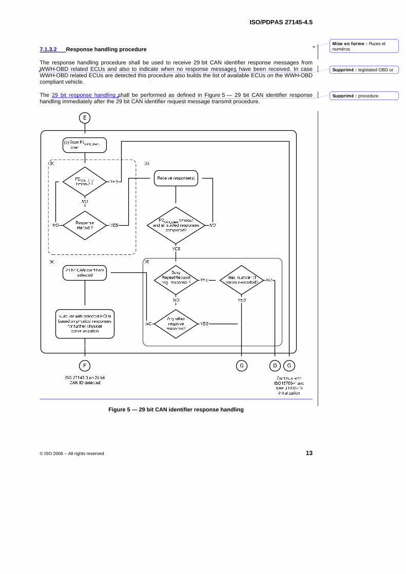
ISO/PDPAS 27145-4.5
© ISO 2006 – All rights reserved 13
7.1.3.2 Response handling procedure
The response handling procedure shall be used to receive 29 bit CAN identifier response messages from WWH-OBD related ECUs and also to indicate when no response messages have been received. In case WWH-OBD related ECUs are detected this procedure also builds the list of available ECUs on the WWH-OBD compliant vehicle.
The 29 bit response handling shall be performed as defined in Figure 5 — 29 bit CAN identifier response handling immediately after the 29 bit CAN identifier request message transmit procedure.
Figure 5 — 29 bit CAN identifier response handling
Mise en forme : Puces etnuméros
Supprimé : legislated OBD or
Supprimé : procedure
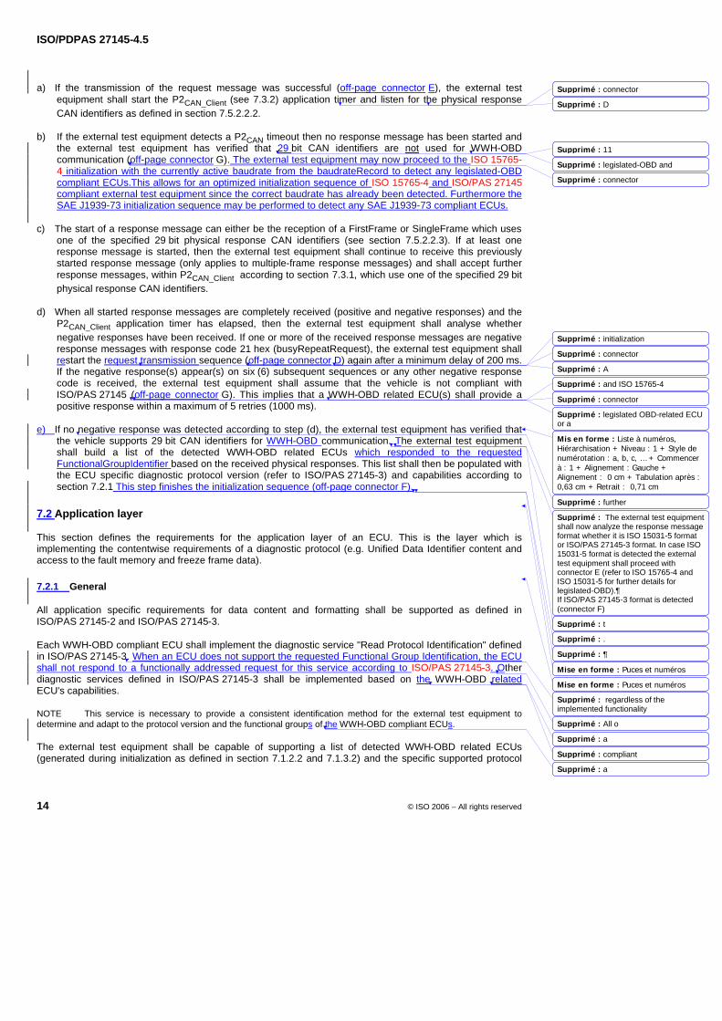
ISO/PDPAS 27145-4.5
14 © ISO 2006 – All rights reserved
a) If the transmission of the request message was successful (off-page connector E), the external test equipment shall start the P2CAN_Client (see 7.3.2) application timer and listen for the physical response CAN identifiers as defined in section 7.5.2.2.2.
b) If the external test equipment detects a P2CAN timeout then no response message has been started and the external test equipment has verified that 29 bit CAN identifiers are not used for WWH-OBD communication (off-page connector G). The external test equipment may now proceed to the ISO 15765-4 initialization with the currently active baudrate from the baudrateRecord to detect any legislated-OBD compliant ECUs.This allows for an optimized initialization sequence of ISO 15765-4 and ISO/PAS 27145 compliant external test equipment since the correct baudrate has already been detected. Furthermore the SAE J1939-73 initialization sequence may be performed to detect any SAE J1939-73 compliant ECUs.
c) The start of a response message can either be the reception of a FirstFrame or SingleFrame which uses one of the specified 29 bit physical response CAN identifiers (see section 7.5.2.2.3). If at least one response message is started, then the external test equipment shall continue to receive this previously started response message (only applies to multiple-frame response messages) and shall accept further response messages, within P2CAN_Client according to section 7.3.1, which use one of the specified 29 bit physical response CAN identifiers.
d) When all started response messages are completely received (positive and negative responses) and the P2CAN_Client application timer has elapsed, then the external test equipment shall analyse whether negative responses have been received. If one or more of the received response messages are negative response messages with response code 21 hex (busyRepeatRequest), the external test equipment shall restart the request transmission sequence (off-page connector D) again after a minimum delay of 200 ms. If the negative response(s) appear(s) on six (6) subsequent sequences or any other negative response code is received, the external test equipment shall assume that the vehicle is not compliant with ISO/PAS 27145 (off-page connector G). This implies that a WWH-OBD related ECU(s) shall provide a positive response within a maximum of 5 retries (1000 ms).
e) If no negative response was detected according to step (d), the external test equipment has verified that the vehicle supports 29 bit CAN identifiers for WWH-OBD communication. The external test equipment shall build a list of the detected WWH-OBD related ECUs which responded to the requested FunctionalGroupIdentifier based on the received physical responses. This list shall then be populated with the ECU specific diagnostic protocol version (refer to ISO/PAS 27145-3) and capabilities according to section 7.2.1 This step finishes the initialization sequence (off-page connector F).
7.2 Application layer
This section defines the requirements for the application layer of an ECU. This is the layer which is implementing the contentwise requirements of a diagnostic protocol (e.g. Unified Data Identifier content and access to the fault memory and freeze frame data).
7.2.1 General
All application specific requirements for data content and formatting shall be supported as defined in ISO/PAS 27145-2 and ISO/PAS 27145-3.
Each WWH-OBD compliant ECU shall implement the diagnostic service "Read Protocol Identification" defined in ISO/PAS 27145-3. When an ECU does not support the requested Functional Group Identification, the ECU shall not respond to a functionally addressed request for this service according to ISO/PAS 27145-3. Other diagnostic services defined in ISO/PAS 27145-3 shall be implemented based on the WWH-OBD related ECU's capabilities.
NOTE This service is necessary to provide a consistent identification method for the external test equipment to determine and adapt to the protocol version and the functional groups of the WWH-OBD compliant ECUs.
The external test equipment shall be capable of supporting a list of detected WWH-OBD related ECUs (generated during initialization as defined in section 7.1.2.2 and 7.1.3.2) and the specific supported protocol
Mis en forme : Liste à numéros,Hiérarchisation + Niveau : 1 + Style denumérotation : a, b, c, … + Commencerà : 1 + Alignement : Gauche +Alignement : 0 cm + Tabulation après : 0,63 cm + Retrait : 0,71 cm
Mise en forme : Puces et numéros
Mise en forme : Puces et numéros
Supprimé : connector
Supprimé : D
Supprimé : 11
Supprimé : legislated-OBD and
Supprimé : connector
Supprimé : initialization
Supprimé : connector
Supprimé : A
Supprimé : and ISO 15765-4
Supprimé : connector
Supprimé : legislated OBD-related ECU or a
Supprimé : further
Supprimé : The external test equipment shall now analyze the response message format whether it is ISO 15031-5 format or ISO/PAS 27145-3 format. In case ISO 15031-5 format is detected the external test equipment shall proceed with connector E (refer to ISO 15765-4 and ISO 15031-5 for further details for legislated-OBD).¶If ISO/PAS 27145-3 format is detected (connector F)
Supprimé : t
Supprimé : .
Supprimé : 
Supprimé : regardless of the implemented functionality
Supprimé : All o
Supprimé : a
Supprimé : compliant
Supprimé : a
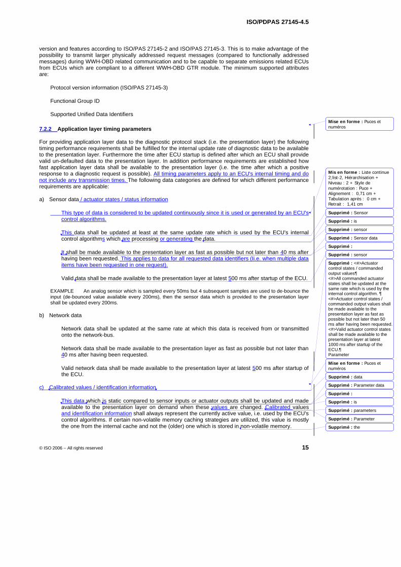
ISO/PDPAS 27145-4.5
© ISO 2006 – All rights reserved 15
version and features according to ISO/PAS 27145-2 and ISO/PAS 27145-3. This is to make advantage of the possibility to transmit larger physically addressed request messages (compared to functionally addressed messages) during WWH-OBD related communication and to be capable to separate emissions related ECUs from ECUs which are compliant to a different WWH-OBD GTR module. The minimum supported attributes are:
Protocol version information (ISO/PAS 27145-3)
Functional Group ID
Supported Unified Data Identifiers
7.2.2 Application layer timing parameters
For providing application layer data to the diagnostic protocol stack (i.e. the presentation layer) the following timing performance requirements shall be fulfilled for the internal update rate of diagnostic data to be available to the presentation layer. Furthermore the time after ECU startup is defined after which an ECU shall provide valid un-defaulted data to the presentation layer. In addition performance requirements are established how fast application layer data shall be available to the presentation layer (i.e. the time after which a positive response to a diagnostic request is possible). All timing parameters apply to an ECU's internal timing and do not include any transmission times. The following data categories are defined for which different performance requirements are applicable:
a) Sensor data / actuator states / status information
This type of data is considered to be updated continuously since it is used or generated by an ECU's control algorithms.
This data shall be updated at least at the same update rate which is used by the ECU's internal control algorithms which are processing or generating the data.
It shall be made available to the presentation layer as fast as possible but not later than 40 ms after having been requested. This applies to data for all requested data identifiers (Ii.e. when multiple data items have been requested in one request).
Valid data shall be made available to the presentation layer at latest 500 ms after startup of the ECU.
EXAMPLE An analog sensor which is sampled every 50ms but 4 subsequent samples are used to de-bounce the input (de-bounced value available every 200ms), then the sensor data which is provided to the presentation layer shall be updated every 200ms.
b) Network data
Network data shall be updated at the same rate at which this data is received from or transmitted onto the network-bus.
Network data shall be made available to the presentation layer as fast as possible but not later than 40 ms after having been requested.
Valid network data shall be made available to the presentation layer at latest 500 ms after startup of the ECU.
c) Calibrated values / identification information
This data which is static compared to sensor inputs or actuator outputs shall be updated and made available to the presentation layer on demand when these values are changed. Calibrated values and identification information shall always represent the currently active value, i.e. used by the ECU's control algorithms. If certain non-volatile memory caching strategies are utilized, this value is mostly the one from the internal cache and not the (older) one which is stored in non-volatile memory.
Mise en forme : Puces etnuméros
Mis en forme : Liste continue2;list-2, Hiérarchisation +Niveau : 2 + Style denumérotation : Puce +Alignement : 0,71 cm +Tabulation après : 0 cm +Retrait : 1,41 cm
Mise en forme : Puces etnuméros
Supprimé : Sensor
Supprimé : is
Supprimé : sensor
Supprimé : Sensor data
Supprimé :
Supprimé : sensor
Supprimé : <#>Actuator control states / commanded output values¶<#>All commanded actuator states shall be updated at the same rate which is used by the internal control algorithm. ¶<#>Actuator control states / commanded output values shall be made available to the presentation layer as fast as possible but not later than 50 ms after having been requested.<#>Valid actuator control states shall be made available to the presentation layer at latest 1000 ms after startup of the ECU.¶Parameter
Supprimé : data
Supprimé : Parameter data
Supprimé :
Supprimé : is
Supprimé : parameters
Supprimé : Parameter
Supprimé : the
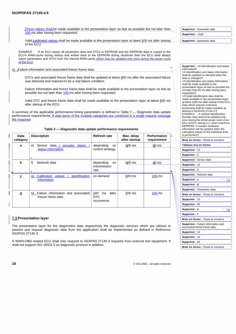
ISO/PDPAS 27145-4.5
16 © ISO 2006 – All rights reserved
These values shall be made available to the presentation layer as fast as possible but not later than 100 ms after having been requested.
Valid calibrated values shall be made available to the presentation layer at latest 500 ms after startup of the ECU.
EXAMPLE If an ECU stores all parametric data and DTCs in EEPROM and the EEPROM data is copied to the ECU's RAM-cache during startup and written back to the EEPROM during shutdown then the ECU shall always report parameters and DTCs from the internal RAM-cache which may be updated only once during the power cycle of the ECU.
d) Failure information and associated freeze frame data
DTCs and associated freeze frame data shall be updated at latest 500 ms after the associated failure was detected and matured to be a real failure condition.
Failure information and freeze frame data shall be made available to the presentation layer as fast as possible but not later than 100 ms after having been requested.
Valid DTC and freeze frame data shall be made available to the presentation layer at latest 500 ms after startup of the ECU.
A summary of the applicable performance timing parameters is defined in Table 2 — Diagnostic data update performance requirements. If data items of the multiple categories are combined in a single request message the response
Table 2 — Diagnostic data update performance requirements
Data category
Description Refresh rate Max. delay after startup
Performance requirement
a e) Sensor data / actuator states / status information
depending on control strategy
500 ms 40 ms
b f) Network data
depending on transmission rate
500 ms 40 ms
c g) Calibrated values / identification information
on demand 500 ms 100 ms
d h) Failure information and associated freeze frame data
500 ms after DTC occurrence
500 ms 100 ms
7.3 Presentation layer
The presentation layer for the diagnostics data respectively the diagnostic services which are utilized to present and request diagnostic data from the application shall be implemented as defined in Reference ISO/PAS 27145-3.
A WWH-OBD related ECU shall only respond to ISO/PAS 27145-3 requests from external test equipment. It shall not support ISO 15031-5 as diagnostic protocol in addition.
Mise en forme : Puces et numéros
Tableau mis en forme
Mise en forme : Puces et numéros
Mise en forme : Puces et numéros
Mise en forme : Puces et numéros
Supprimé : Parameter data
Supprimé : shall
Supprimé : parametric data
Supprimé : <#>Identification and status information¶<#>Identification and status information shall be updated on demand when the data is changed.¶<#>Identification and status information shall be made available to the presentation layer as fast as possible but not later than 80 ms after having been requested.¶<#>Valid identification data shall be made available to the presentation layer at latest 1000 ms after startup of the ECU. Data which requires extensive processing shall be made available as defined in ISO/PAS 27145-2.¶EXAMPLE A Vehicle Identification Number may need to be updated only once during the whole power cycle of an ECU at ECU startup (i.e. when read from EEPROM). A monitor readiness information will be updated when the calculation based on the individual tests is performed.
Supprimé : 10
Supprimé : 5
Supprimé : Sensor data
Supprimé : 10
Supprimé : 5
Supprimé : Network data
Supprimé : c
Supprimé : d
Supprimé : Parametric data
Supprimé : 10
Supprimé : 80
Supprimé : e
Supprimé : f
Supprimé : Failure information and associated freeze frame data
Supprimé : 10
Supprimé : 10
Supprimé : 80
... [2]
... [1]
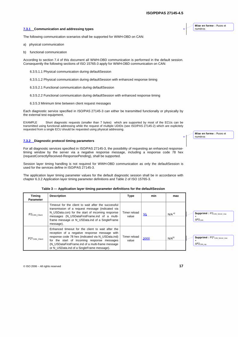
ISO/PDPAS 27145-4.5
© ISO 2006 – All rights reserved 17
7.3.1 Communication and addressing types
The following communication scenarios shall be supported for WWH-OBD on CAN:
a) physical communication
b) functional communication
According to section 7.4 of this document all WWH-OBD communication is performed in the default session. Consequently the following sections of ISO 15765-3 apply for WWH-OBD communication on CAN:
6.3.5.1.1 Physical communication during defaultSession
6.3.5.1.2 Physical communication during defaultSession with enhanced response timing
6.3.5.2.1 Functional communication during defaultSession
6.3.5.2.2 Functional communication during defaultSession with enhanced response timing
6.3.5.3 Minimum time between client request messages
Each diagnostic service specified in ISO/PAS 27145-3 can either be transmitted functionally or physically by the external test equipment.
EXAMPLE Short diagnostic requests (smaller than 7 bytes) which are supported by most of the ECUs can be transmitted using functional addressing while the request of multiple UDIDs (see ISO/PAS 27145-2) which are explicitely requested from a single ECU should be requested using physical addressing.
7.3.2 Diagnostic protocol timing parameters
For all diagnostic services specified in ISO/PAS 27145-3, the possibility of requesting an enhanced response-timing window by the server via a negative response message, including a response code 78 hex (requestCorrectlyReceived-ResponsePending), shall be supported.
Session layer timing handling is not required for WWH-OBD communication as only the defaultSession is used for the services define in ISO/PAS 27145-3.
The application layer timing parameter values for the default diagnostic session shall be in accordance with chapter 6.3.2 Application layer timing parameter definitions and Table 2 of ISO 15765-3.
Table 3 — Application layer timing parameter definitions for the defaultSession
Timing Parameter
Description Type min max
P2CAN_Client
Timeout for the client to wait after the successful transmission of a request message (indicated via N_USData.con) for the start of incoming response messages (N_USDataFirstFrame.ind of a multi-frame message or N_USData.ind of a SingleFrame message).
Timer reload value
50 N/A a)
P2*CAN_Client
Enhanced timeout for the client to wait after the reception of a negative response message with response code 78 hex (indicated via N_USData.ind) for the start of incoming response messages (N_USDataFirstFrame.ind of a multi-frame message or N_USData.ind of a SingleFrame message).
Timer reload value
5000 N/Ab)
Mise en forme : Puces etnuméros
Mise en forme : Puces etnuméros
Supprimé : P2CAN_Server_max
+∆P2CAN
Supprimé : P2*CAN_Server_max
+∆P2CAN_rsp
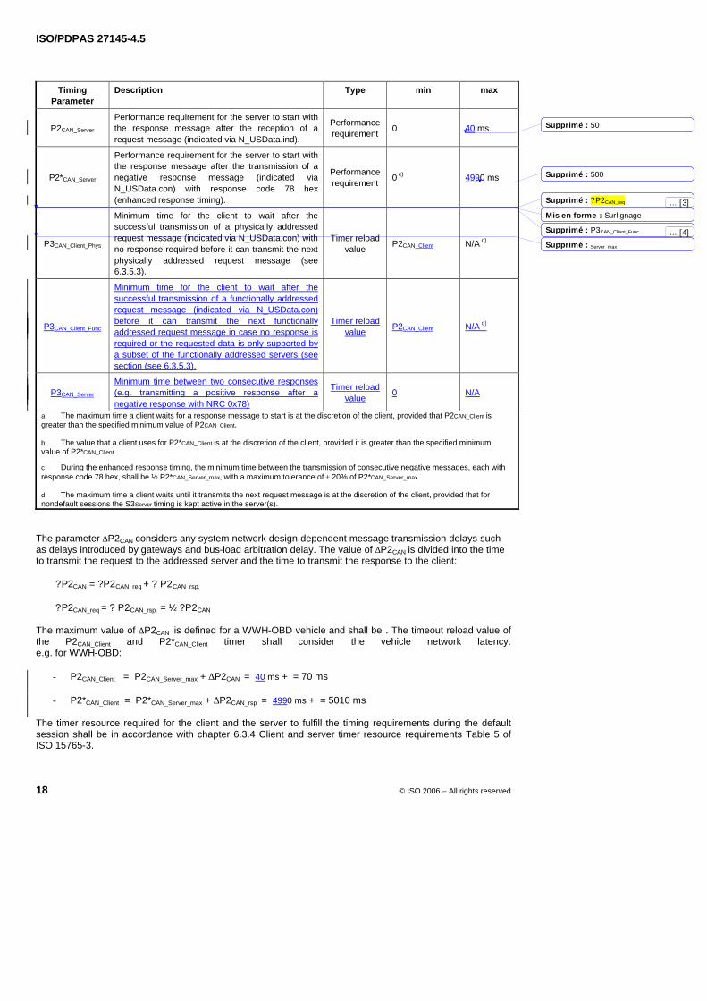
ISO/PDPAS 27145-4.5
18 © ISO 2006 – All rights reserved
Timing Parameter
Description Type min max
P2CAN_Server Performance requirement for the server to start with the response message after the reception of a request message (indicated via N_USData.ind).
Performance requirement
0 40 ms
P2*CAN_Server
Performance requirement for the server to start with the response message after the transmission of a negative response message (indicated via N_USData.con) with response code 78 hex (enhanced response timing).
Performance requirement
0 c) 4990 ms
P3CAN_Client_Phys
Minimum time for the client to wait after the successful transmission of a physically addressed request message (indicated via N_USData.con) with no response required before it can transmit the next physically addressed request message (see 6.3.5.3).
Timer reload value
P2CAN_Client N/A d)
P3CAN_Client_Func
Minimum time for the client to wait after the successful transmission of a functionally addressed request message (indicated via N_USData.con) before it can transmit the next functionally addressed request message in case no response is required or the requested data is only supported by a subset of the functionally addressed servers (see section (see 6.3.5.3).
Timer reload value
P2CAN_Client N/A d)
P3CAN_Server Minimum time between two consecutive responses (e.g. transmitting a positive response after a negative response with NRC 0x78)
Timer reload value
0 N/A
a The maximum time a client waits for a response message to start is at the discretion of the client, provided that P2CAN_Client is greater than the specified minimum value of P2CAN_Client. b The value that a client uses for P2*CAN_Client is at the discretion of the client, provided it is greater than the specified minimum value of P2*CAN_Client. c During the enhanced response timing, the minimum time between the transmission of consecutive negative messages, each with response code 78 hex, shall be ½ P2*CAN_Server_max, with a maximum tolerance of ± 20% of P2*CAN_Server_max.. d The maximum time a client waits until it transmits the next request message is at the discretion of the client, provided that for nondefault sessions the S3Server timing is kept active in the server(s).
The parameter ∆P2CAN considers any system network design-dependent message transmission delays such as delays introduced by gateways and bus-load arbitration delay. The value of ∆P2CAN is divided into the time to transmit the request to the addressed server and the time to transmit the response to the client: ?P2CAN = ?P2CAN_req + ? P2CAN_rsp.
?P2CAN_req = ? P2CAN_rsp. = ½ ?P2CAN
The maximum value of ∆P2CAN is defined for a WWH-OBD vehicle and shall be . The timeout reload value of the P2CAN_Client and P2*CAN_Client timer shall consider the vehicle network latency. e.g. for WWH-OBD:
- P2CAN_Client = P2CAN_Server_max + ∆P2CAN = 40 ms + = 70 ms
- P2*CAN_Client = P2*CAN_Server_max + ∆P2CAN_rsp = 4990 ms + = 5010 ms
The timer resource required for the client and the server to fulfill the timing requirements during the default session shall be in accordance with chapter 6.3.4 Client and server timer resource requirements Table 5 of ISO 15765-3.
Mis en forme : Surlignage
Supprimé : 50
Supprimé : 500
Supprimé : ?P2CAN_req
Supprimé : P3CAN_Client_Func
Supprimé : Server_max
... [3]
... [4]
ISO/PDPAS 27145-4.5
© ISO 2006 – All rights reserved 19
7.4 Session layer
All WWH-OBD communication shall take place during the default diagnostic session.
There shall always be exactly one diagnostic session active in a WWH-OBD related ECU. A WWH-OBD related ECU shall always start the default diagnostic session when powered up. If no other diagnostic session is started, then the default diagnostic session shall be running as long as the WWH-OBD related ECU is powered.
A WWH-OBD related ECU shall be capable of providing all diagnostic functionality defined for WWH-OBD in the default diagnostic session and under normal operating conditions.
NOTE If in multi-tester environments (e.g. additional on-vehicle monitoring unit) a different session is active while an external test tool transmits requests then the default diagnostic session only needs to be entered if the WWH-OBD communication requirements (incl. application requirements) can not be fulfilled in the currently active non-default session.
There shall be no need for any diagnostic service to be sent to the WWH-OBD related ECU to keep the default diagnostic session active.
7.5 Network layer
The network layer of the external test equipment and the legislated-OBD-compliant vehicle ECU(s) — from the external test equipment point of view — shall be in accordance with ISO 15765-2 and the restrictions/additions defined in 7.5.1 through 7.5.7.
7.5.1 Addressing formats
For WWH-OBD communication, only the normal addressing format — in case of 11 bit CAN identifiers are used— and only the normal fixed addressing format — in case of 29 bit CAN identifiers are used — as defined in ISO 15765-2, shall be used.
7.5.2 Data link layer interface
7.5.2.1 CAN identifier requirements
7.5.2.1.1 External test equipment
The external test equipment shall support 11 bit and 29 bit CAN identifiers for WWH-OBD communication, for which it shall only accept CAN identifiers which fit into the defined WWH-OBD CAN identifier ranges for 11 bit or 29 bit CAN identifiers (see 7.5.2.2).
For WWH-OBD communication following the initialization sequence, the external test equipment shall only use 11 bit or 29 bit CAN identifiers depending on the format which was detected during the initialization sequence.
7.5.2.1.2 WWH-OBD ECUs
A WWH-OBD-compliant vehicle shall use either 11 bit or 29 bit CAN identifier format. The CAN-identfier formats shall not be mixed (11 bit and 29 bit format on one vehicle) for WWH-OBD communication.
From the external test equipment point of view each WWH-OBD server in one WWH-OBD compliant vehicle shall:
support either 11 bit or 29 bit CAN identifiers for WWH-OBD request and response messages.
support one pair of physical request and response CAN identifiers as specified in section 7.5.2.2.1.
accept the functional request CAN identifier of the supported CAN identifier set (11 bit or 29 bit) for functionally addressed WWH-OBD request messages.
Mise en forme : Puces etnuméros
Mise en forme : Puces etnuméros
Mise en forme : Puces etnuméros
Mise en forme : Puces etnuméros
Mise en forme : Puces etnuméros
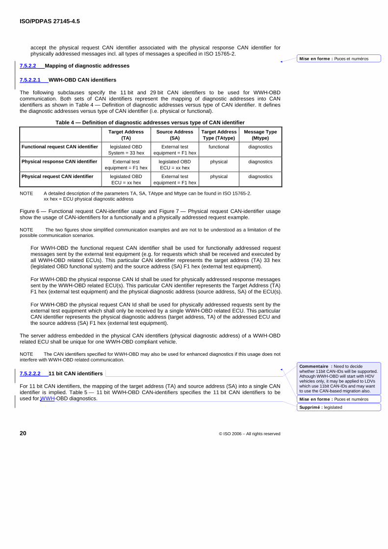
ISO/PDPAS 27145-4.5
20 © ISO 2006 – All rights reserved
accept the physical request CAN identifier associated with the physical response CAN identifier for physically addressed messages incl. all types of messages a specified in ISO 15765-2.
7.5.2.2 Mapping of diagnostic addresses
7.5.2.2.1 WWH-OBD CAN identifiers
The following subclauses specify the 11 bit and 29 bit CAN identifiers to be used for WWH-OBD communication. Both sets of CAN identifiers represent the mapping of diagnostic addresses into CAN identifiers as shown in Table 4 — Definition of diagnostic addresses versus type of CAN identifier. It defines the diagnostic addresses versus type of CAN identifier (i.e. physical or functional).
Table 4 — Definition of diagnostic addresses versus type of CAN identifier
Target Address (TA)
Source Address (SA)
Target Address Type (TAtype)
Message Type (Mtype)
Functional request CAN identifier legislated OBD System = 33 hex
External test equipment = F1 hex
functional diagnostics
Physical response CAN identifier External test equipment = F1 hex
legislated OBD ECU = xx hex
physical diagnostics
Physical request CAN identifier legislated OBD ECU = xx hex
External test equipment = F1 hex
physical diagnostics
NOTE A detailed description of the parameters TA, SA, TAtype and Mtype can be found in ISO 15765-2. xx hex = ECU physical diagnostic address
Figure 6 — Functional request CAN-identifier usage and Figure 7 — Physical request CAN-identifier usage show the usage of CAN-identifiers for a functionally and a physically addressed request example.
NOTE The two figures show simplified communication examples and are not to be understood as a limitation of the possible communication scenarios.
For WWH-OBD the functional request CAN identifier shall be used for functionally addressed request messages sent by the external test equipment (e.g. for requests which shall be received and executed by all WWH-OBD related ECUs). This particular CAN identifier represents the target address (TA) 33 hex (legislated OBD functional system) and the source address (SA) F1 hex (external test equipment).
For WWH-OBD the physical response CAN Id shall be used for physically addressed response messages sent by the WWH-OBD related ECU(s). This particular CAN identifier represents the Target Address (TA) F1 hex (external test equipment) and the physical diagnostic address (source address, SA) of the ECU(s).
For WWH-OBD the physical request CAN Id shall be used for physically addressed requests sent by the external test equipment which shall only be received by a single WWH-OBD related ECU. This particular CAN identifier represents the physical diagnostic address (target address, TA) of the addressed ECU and the source address (SA) F1 hex (external test equipment).
The server address embedded in the physical CAN identifiers (physical diagnostic address) of a WWH-OBD related ECU shall be unique for one WWH-OBD compliant vehicle.
NOTE The CAN identifiers specified for WWH-OBD may also be used for enhanced diagnostics if this usage does not interfere with WWH-OBD related communication.
7.5.2.2.2 11 bit CAN identifiers
For 11 bit CAN identifiers, the mapping of the target address (TA) and source address (SA) into a single CAN identifier is implied. Table 5 — 11 bit WWH-OBD CAN-identifiers specifies the 11 bit CAN identifiers to be used for WWH-OBD diagnostics.
Mise en forme : Puces et numéros
Mise en forme : Puces et numéros
Commentaire : Need to decide whether 11bit CAN-IDs will be supported. Athough WWH-OBD will start with HDV vehicles only, it may be applied to LDVs which use 11bit CAN-IDs and may want to use the CAN-based migration also.
Supprimé : legislated
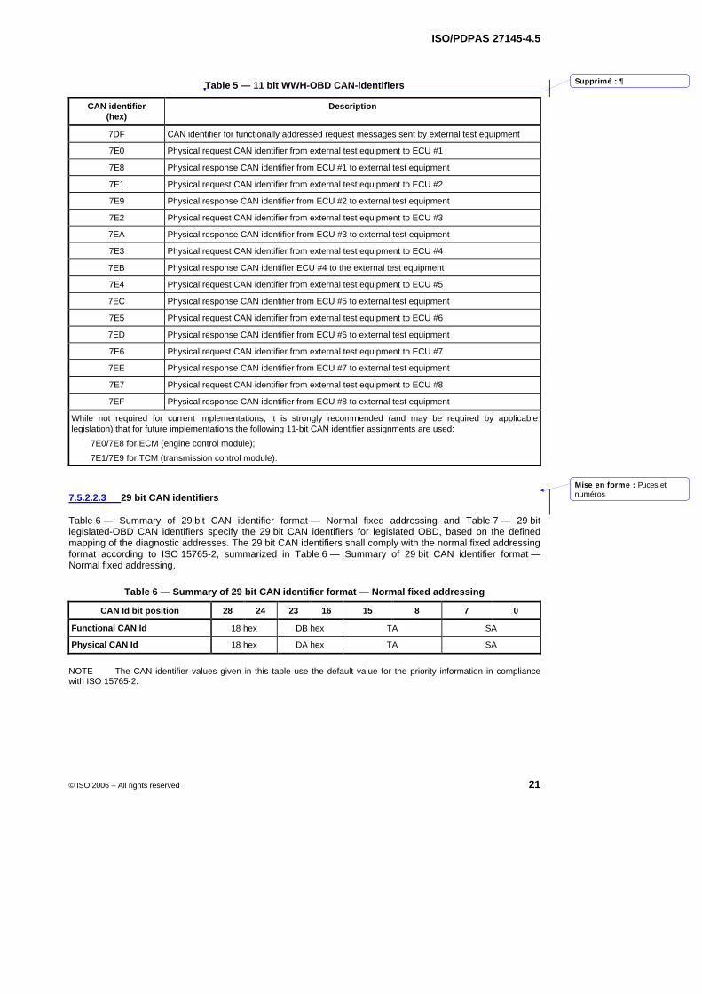
ISO/PDPAS 27145-4.5
© ISO 2006 – All rights reserved 21
Table 5 — 11 bit WWH-OBD CAN-identifiers
CAN identifier (hex)
Description
7DF CAN identifier for functionally addressed request messages sent by external test equipment
7E0 Physical request CAN identifier from external test equipment to ECU #1
7E8 Physical response CAN identifier from ECU #1 to external test equipment
7E1 Physical request CAN identifier from external test equipment to ECU #2
7E9 Physical response CAN identifier from ECU #2 to external test equipment
7E2 Physical request CAN identifier from external test equipment to ECU #3
7EA Physical response CAN identifier from ECU #3 to external test equipment
7E3 Physical request CAN identifier from external test equipment to ECU #4
7EB Physical response CAN identifier ECU #4 to the external test equipment
7E4 Physical request CAN identifier from external test equipment to ECU #5
7EC Physical response CAN identifier from ECU #5 to external test equipment
7E5 Physical request CAN identifier from external test equipment to ECU #6
7ED Physical response CAN identifier from ECU #6 to external test equipment
7E6 Physical request CAN identifier from external test equipment to ECU #7
7EE Physical response CAN identifier from ECU #7 to external test equipment
7E7 Physical request CAN identifier from external test equipment to ECU #8
7EF Physical response CAN identifier from ECU #8 to external test equipment
While not required for current implementations, it is strongly recommended (and may be required by applicable legislation) that for future implementations the following 11-bit CAN identifier assignments are used:
7E0/7E8 for ECM (engine control module);
7E1/7E9 for TCM (transmission control module).
7.5.2.2.3 29 bit CAN identifiers
Table 6 — Summary of 29 bit CAN identifier format — Normal fixed addressing and Table 7 — 29 bit legislated-OBD CAN identifiers specify the 29 bit CAN identifiers for legislated OBD, based on the defined mapping of the diagnostic addresses. The 29 bit CAN identifiers shall comply with the normal fixed addressing format according to ISO 15765-2, summarized in Table 6 — Summary of 29 bit CAN identifier format — Normal fixed addressing.
Table 6 — Summary of 29 bit CAN identifier format — Normal fixed addressing
CAN Id bit position 28 24 23 16 15 8 7 0
Functional CAN Id 18 hex DB hex TA SA
Physical CAN Id 18 hex DA hex TA SA
NOTE The CAN identifier values given in this table use the default value for the priority information in compliance with ISO 15765-2.
Mise en forme : Puces etnuméros
Supprimé : 
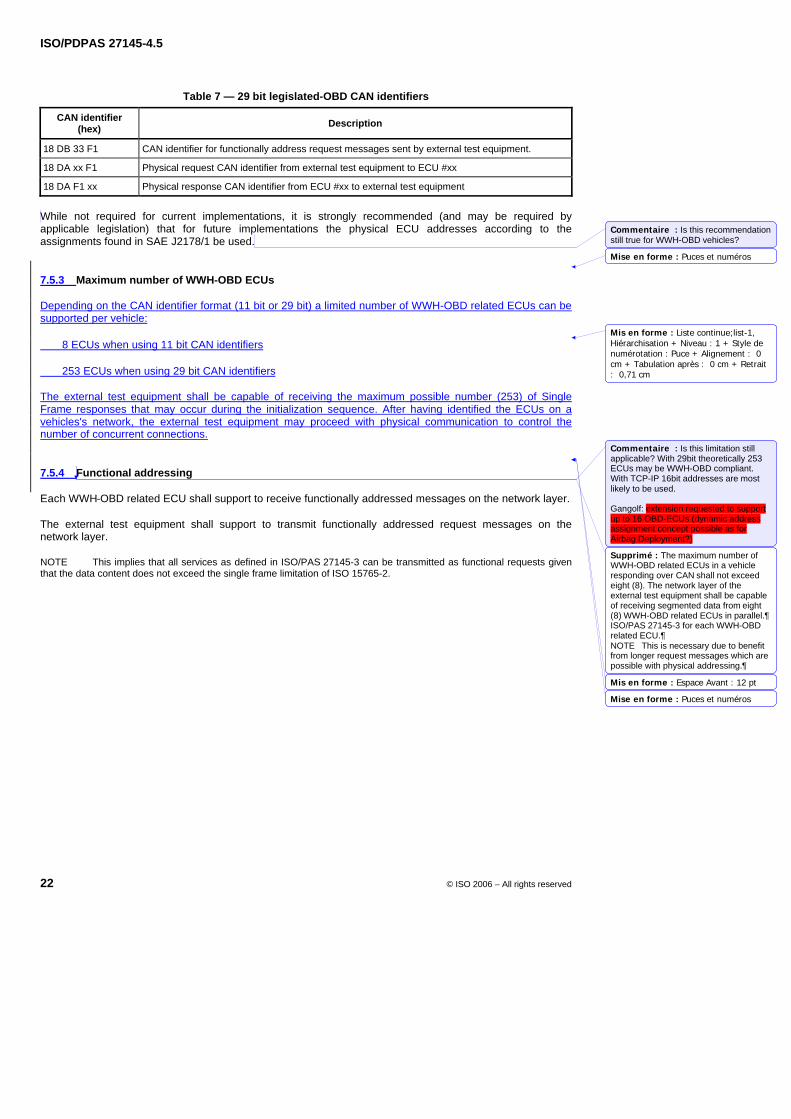
ISO/PDPAS 27145-4.5
22 © ISO 2006 – All rights reserved
Table 7 — 29 bit legislated-OBD CAN identifiers
CAN identifier (hex) Description
18 DB 33 F1 CAN identifier for functionally address request messages sent by external test equipment.
18 DA xx F1 Physical request CAN identifier from external test equipment to ECU #xx
18 DA F1 xx Physical response CAN identifier from ECU #xx to external test equipment
While not required for current implementations, it is strongly recommended (and may be required by applicable legislation) that for future implementations the physical ECU addresses according to the assignments found in SAE J2178/1 be used.
7.5.3 Maximum number of WWH-OBD ECUs
Depending on the CAN identifier format (11 bit or 29 bit) a limited number of WWH-OBD related ECUs can be supported per vehicle:
8 ECUs when using 11 bit CAN identifiers
253 ECUs when using 29 bit CAN identifiers
The external test equipment shall be capable of receiving the maximum possible number (253) of Single Frame responses that may occur during the initialization sequence. After having identified the ECUs on a vehicles's network, the external test equipment may proceed with physical communication to control the number of concurrent connections.
7.5.4 Functional addressing
Each WWH-OBD related ECU shall support to receive functionally addressed messages on the network layer.
The external test equipment shall support to transmit functionally addressed request messages on the network layer.
NOTE This implies that all services as defined in ISO/PAS 27145-3 can be transmitted as functional requests given that the data content does not exceed the single frame limitation of ISO 15765-2.
Mise en forme : Puces et numéros
Mis en forme : Liste continue;list-1,Hiérarchisation + Niveau : 1 + Style denumérotation : Puce + Alignement : 0cm + Tabulation après : 0 cm + Retrait: 0,71 cm
Mis en forme : Espace Avant : 12 pt
Mise en forme : Puces et numéros
Commentaire : Is this recommendation still true for WWH-OBD vehicles?
Commentaire : Is this limitation still applicable? With 29bit theoretically 253 ECUs may be WWH-OBD compliant. With TCP-IP 16bit addresses are most likely to be used. Gangolf: extension requested to support up to 16 OBD-ECUs (dynamic address assignment concept possible as for Airbag Deployment?)
Supprimé : The maximum number of WWH-OBD related ECUs in a vehicle responding over CAN shall not exceed eight (8). The network layer of the external test equipment shall be capable of receiving segmented data from eight (8) WWH-OBD related ECUs in parallel.¶ISO/PAS 27145-3 for each WWH-OBD related ECU.¶NOTE This is necessary due to benefit from longer request messages which are possible with physical addressing.
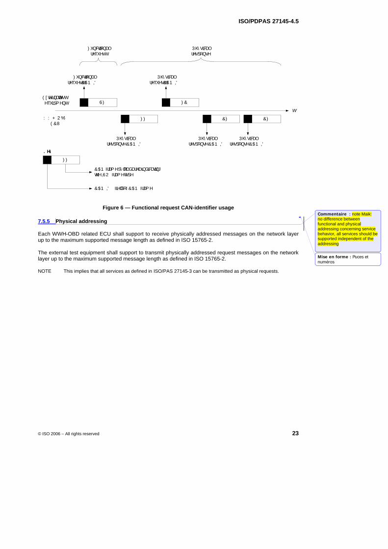
ISO/PDPAS 27145-4.5
© ISO 2006 – All rights reserved 23
) XQFWLRQDOUHTXHVW
( [ WHUQDOWHVWHTXLSP HQW
: : + 2 %'( &8
3K\ VLFDOUHVSRQVH
) XQFWLRQDOUHTXHVW&$1 ,'
3K\ VLFDOUHTXHVW&$1 ,'
3K\ VLFDOUHVSRQVH&$1 ,'
3K\ VLFDOUHVSRQVH&$1 ,'
3K\ VLFDOUHVSRQVH&$1 ,'
W
6)
) )
) &
&) &)
) )
. H\
&$1 IUDP HS\ ORDGDUHDLQGLFDWLQJWKH,62 IUDP HW\ SH
&$1 ,' ILHOGRI&$1 IUDP H
Figure 6 — Functional request CAN-identifier usage
7.5.5 Physical addressing
Each WWH-OBD related ECU shall support to receive physically addressed messages on the network layer up to the maximum supported message length as defined in ISO 15765-2.
The external test equipment shall support to transmit physically addressed request messages on the network layer up to the maximum supported message length as defined in ISO 15765-2.
NOTE This implies that all services as defined in ISO/PAS 27145-3 can be transmitted as physical requests.
Mise en forme : Puces etnuméros
Commentaire : note Maik: no difference between functional and physical addressing concerning service behavior, all services should be supported independent of the addressing
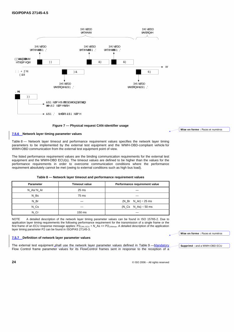
ISO/PDPAS 27145-4.5
24 © ISO 2006 – All rights reserved
3K\ VLFDOUHVSRQVH
( [ WHUQDOWHVWHTXLSP HQW
: : + 2 %'( &8
3K\ VLFDOUHTXHVW
3K\ VLFDOUHTXHVW&$1 ,'
3K\ VLFDOUHTXHVW&$1 ,'
3K\ VLFDOUHVSRQVH&$1 ,'
3K\ VLFDOUHTXHVW&$1 ,'
3K\ VLFDOUHVSRQVH&$1 ,'
W
&)
6)
&)
) &
) )
) )
. H\
&$1 IUDP HS\ ORDGDUHDLQGLFDWLQJWKH,62 IUDP HW\ SH
&$1 ,' ILHOGRI&$1 IUDP H
Figure 7 — Physical request CAN-identifier usage
7.5.6 Network layer timing parameter values
Table 8 — Network layer timeout and performance requirement values specifies the network layer timing parameters to be implemented by the external test equipment and the WWH-OBD-compliant vehicle for WWH-OBD communication from the external test equipment point of view.
The listed performance requirement values are the binding communication requirements for the external test equipment and the WWH-OBD ECU(s). The timeout values are defined to be higher than the values for the performance requirements in order to overcome communication conditions where the performance requirement absolutely cannot be met (owing to external conditions such as high bus load).
Table 8 — Network layer timeout and performance requirement values
Parameter Timeout value Performance requirement value
N_As/ N_Ar 25 ms —
N_Bs 75 ms —
N_Br — (N_Br + N_Ar) < 25 ms
N_Cs — (N_Cs + N_As) < 50 ms
N_Cr 150 ms —
NOTE A detailed description of the network layer timing parameter values can be found in ISO 15765-2. Due to application layer timing requirements the following performance requirement for the transmission of a single frame or the first frame of an ECU response message applies: P2CAN, ECU + N_As <= P2CANmax. A detailed description of the application layer timing parameter P2 can be found in ISO/PAS 27145-3.
7.5.7 Definition of network layer parameter values
The external test equipment shall use the network layer parameter values defined in Table 9 —Mandatory Flow Control frame parameter values for its FlowControl frames sent in response to the reception of a
Mise en forme : Puces et numéros
Mise en forme : Puces et numéros
Supprimé : and a WWH-OBD ECU
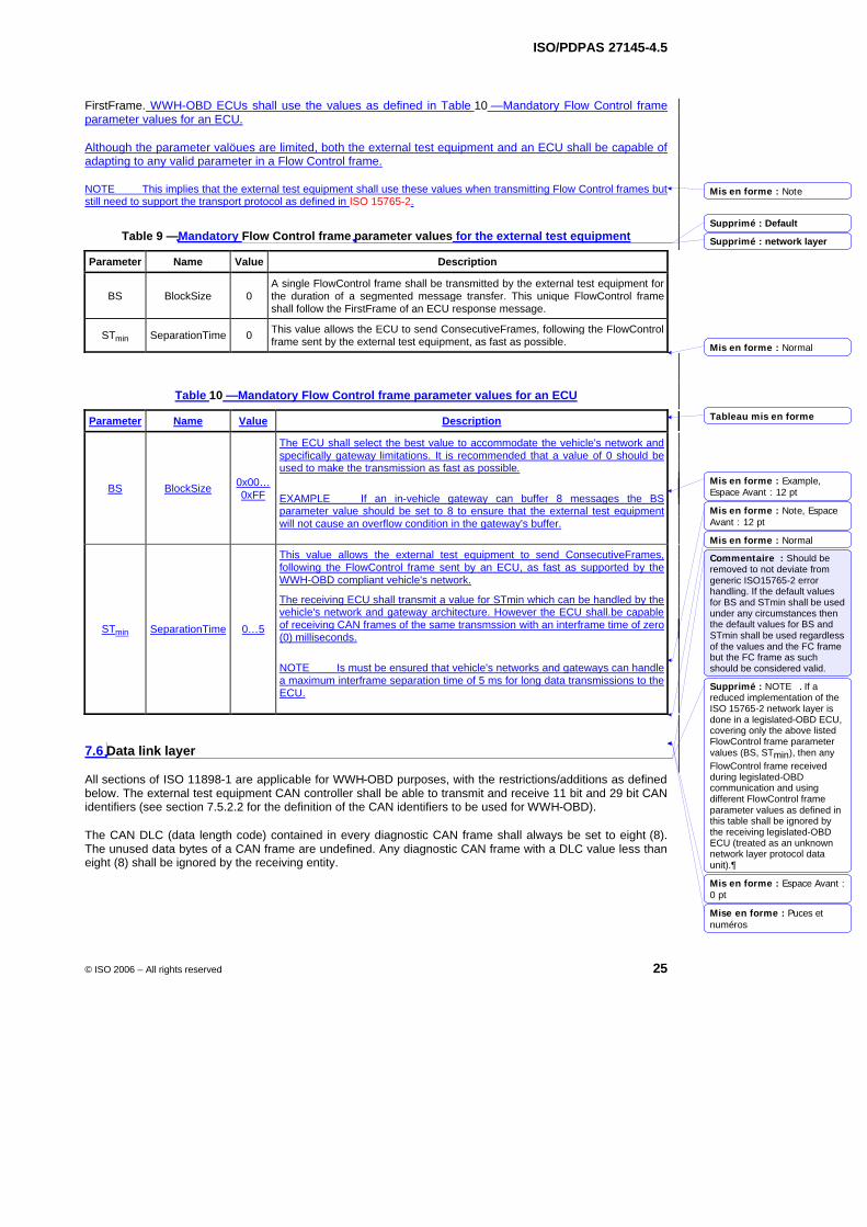
ISO/PDPAS 27145-4.5
© ISO 2006 – All rights reserved 25
FirstFrame. WWH-OBD ECUs shall use the values as defined in Table 10 —Mandatory Flow Control frame parameter values for an ECU.
Although the parameter valöues are limited, both the external test equipment and an ECU shall be capable of adapting to any valid parameter in a Flow Control frame.
NOTE This implies that the external test equipment shall use these values when transmitting Flow Control frames but still need to support the transport protocol as defined in ISO 15765-2.
Table 9 —Mandatory Flow Control frame parameter values for the external test equipment
Parameter Name Value Description
BS BlockSize 0 A single FlowControl frame shall be transmitted by the external test equipment for the duration of a segmented message transfer. This unique FlowControl frame shall follow the FirstFrame of an ECU response message.
STmin SeparationTime 0 This value allows the ECU to send ConsecutiveFrames, following the FlowControl frame sent by the external test equipment, as fast as possible.
Table 10 —Mandatory Flow Control frame parameter values for an ECU
Parameter Name Value Description
BS BlockSize 0x00…0xFF
The ECU shall select the best value to accommodate the vehicle's network and specifically gateway limitations. It is recommended that a value of 0 should be used to make the transmission as fast as possible.
EXAMPLE If an in-vehicle gateway can buffer 8 messages the BS parameter value should be set to 8 to ensure that the external test equipment will not cause an overflow condition in the gateway's buffer.
STmin SeparationTime 0…5
This value allows the external test equipment to send ConsecutiveFrames, following the FlowControl frame sent by an ECU, as fast as supported by the WWH-OBD compliant vehicle's network.
The receiving ECU shall transmit a value for STmin which can be handled by the vehicle's network and gateway architecture. However the ECU shall.be capable of receiving CAN frames of the same transmssion with an interframe time of zero (0) milliseconds.
NOTE Is must be ensured that vehicle's networks and gateways can handle a maximum interframe separation time of 5 ms for long data transmissions to the ECU.
7.6 Data link layer
All sections of ISO 11898-1 are applicable for WWH-OBD purposes, with the restrictions/additions as defined below. The external test equipment CAN controller shall be able to transmit and receive 11 bit and 29 bit CAN identifiers (see section 7.5.2.2 for the definition of the CAN identifiers to be used for WWH-OBD).
The CAN DLC (data length code) contained in every diagnostic CAN frame shall always be set to eight (8). The unused data bytes of a CAN frame are undefined. Any diagnostic CAN frame with a DLC value less than eight (8) shall be ignored by the receiving entity.
Mis en forme : Note
Mis en forme : Normal
Tableau mis en forme
Mis en forme : Example,Espace Avant : 12 pt
Mis en forme : Note, EspaceAvant : 12 pt
Mis en forme : Normal
Mis en forme : Espace Avant :0 pt
Mise en forme : Puces etnuméros
Supprimé : Default
Supprimé : network layer
Commentaire : Should be removed to not deviate from generic ISO15765-2 error handling. If the default values for BS and STmin shall be used under any circumstances then the default values for BS and STmin shall be used regardless of the values and the FC frame but the FC frame as such should be considered valid.
Supprimé : NOTE If a reduced implementation of the ISO 15765-2 network layer is done in a legislated-OBD ECU, covering only the above listed FlowControl frame parameter values (BS, STmin), then any FlowControl frame received during legislated-OBD communication and using different FlowControl frame parameter values as defined in this table shall be ignored by the receiving legislated-OBD ECU (treated as an unknown network layer protocol data unit).
ISO/PDPAS 27145-4.5
26 © ISO 2006 – All rights reserved
7.7 Physical layer
The physical layer and physical signalling of the external test equipment shall be in accordance with IISO 11898-1 and ISO ISO 11898-2, with the following restrictions and additions.
7.7.1 Diagnostic connector
The diagnostic connector provides the connection between the external test equipment and the WWH-OBD compliant vehicle. The connector shall be implemented according to the definitions in ISO 15031-3.
7.7.2 External test equipment baudrates
The external test equipment shall support the WWH-OBD baudrates. These can vary depending on the local legislation. Where the applicable legislation does not specify baudrates, use either
250 kBit/s or
500 kBit/s
7.7.3 External test equipment CAN bit timing
7.7.3.1 CAN bit timing parameter values
The specified CAN bit timing parameter values apply to the external test equipment. The WWH-OBD-compliant vehicle may use different CAN bit timing parameter values to achieve its WWH-OBD-compliant baudrate, however, it shall be able to communicate with the defined external test equipment.
The following specifies the required CAN bit timing parameter settings for the external test equipment based on the timing parameter definitions given in ISO 11898-1. All requirements are specified for operation at 250 kBit/s and 500 kBit/s. The bit timing is according to ISO 11898. The CAN controller shall support the protocol specifications CAN 2.0A (standard format) and CAN 2.0B passive (29 bit ID extended format) and shall be in compliance with ISO 11898.
For example, the enhanced protocol for higher clock tolerance shall be supported (e.g. tolerate 2 bit message intermission) and extended frame messages shall not be disturbed unless bit errors are being detected.
The CAN bit timing parameter values used in this part of ISO/PAS 27145 are based on equivalent terms in ISO 11898-1 (see Figure 8 — Partitioning of CAN bit time):
tSYNCSEG = Sync_Seg = 1 * tQ
tSEG1 = Prop_Seg + Phase_Seg1 = tBIT − tSYNCSEG − tSEG2
tSEG2 = Phase_Seg2
tSJW = resynchronization jump width
tBIT = tB (nominal bit time)
tQ = time quantum
SP = nominal sample point position = (1 − tSEG2/tBIT) * 100 %
NOTE Compliance with the nominal bit time tolerance requirement given in this part of ISO/PAS 27145 is directly dependent on the CAN system clock tolerance of the external test equipment and the programmed nominal bit time value. In a typical CAN controller, the nominal bit time value must be an integer multiple of its system clock periods. When the programmable nominal bit time value is set exactly to the required nominal bit time value, accuracy is only affected by the
Mis en forme : Espace Avant : 12 pt
Mise en forme : Puces et numéros
Mis en forme : Titre 3;h3, Sansnumérotation ni puces
Mise en forme : Puces et numéros
Mise en forme : Puces et numéros
Supprimé : 
Supprimé : 
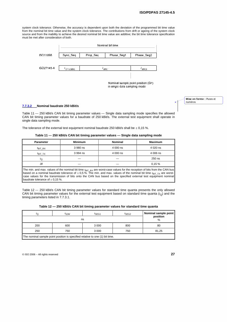
ISO/PDPAS 27145-4.5
© ISO 2006 – All rights reserved 27
system clock tolerance. Otherwise, the accuracy is dependent upon both the deviation of the programmed bit time value from the nominal bit time value and the system clock tolerance. The contributions from drift or ageing of the system clock source and from the inability to achieve the desired nominal bit time value are additive; the bit time tolerance specification must be met after consideration of both.
Figure 8 — Partitioning of CAN bit time
7.7.3.2 Nominal baudrate 250 kBit/s
Table 11 — 250 kBit/s CAN bit timing parameter values — Single data sampling mode specifies the allowed CAN bit timing parameter values for a baudrate of 250 kBit/s. The external test equipment shall operate in single data sampling mode.
The tolerance of the external test equipment nominal baudrate 250 kBit/s shall be ± 0,15 %.
Table 11 — 250 kBit/s CAN bit timing parameter values — Single data sampling mode
Parameter Minimum Nominal Maximum
tBIT_RX 3 980 ns 4 000 ns 4 020 ns
tBIT_TX 3 994 ns 4 000 ns 4 006 ns
tQ — — 250 ns
∆f — — 0,15 %
The min. and max. values of the nominal bit time tBIT_RX are worst-case values for the reception of bits from the CAN bus based on a nominal baudrate tolerance of ± 0,5 %. The min. and max. values of the nominal bit time tBIT_TX are worst-case values for the transmission of bits onto the CAN bus based on the specified external test equipment nominal baudrate tolerance of ± 0,15 %.
Table 12 — 250 kBit/s CAN bit timing parameter values for standard time quanta presents the only allowed CAN bit timing parameter values for the external test equipment based on standard time quanta (tQ) and the timing parameters listed in 7.7.3.1.
Table 12 — 250 kBit/s CAN bit timing parameter values for standard time quanta
tQ tSJW tSEG1 tSEG2
ns
Nominal sample point position
%
200 600 3 000 800 80
250 750 3 000 750 81,25
The nominal sample point position is specified relative to one (1) bit time.
Mise en forme : Puces etnuméros
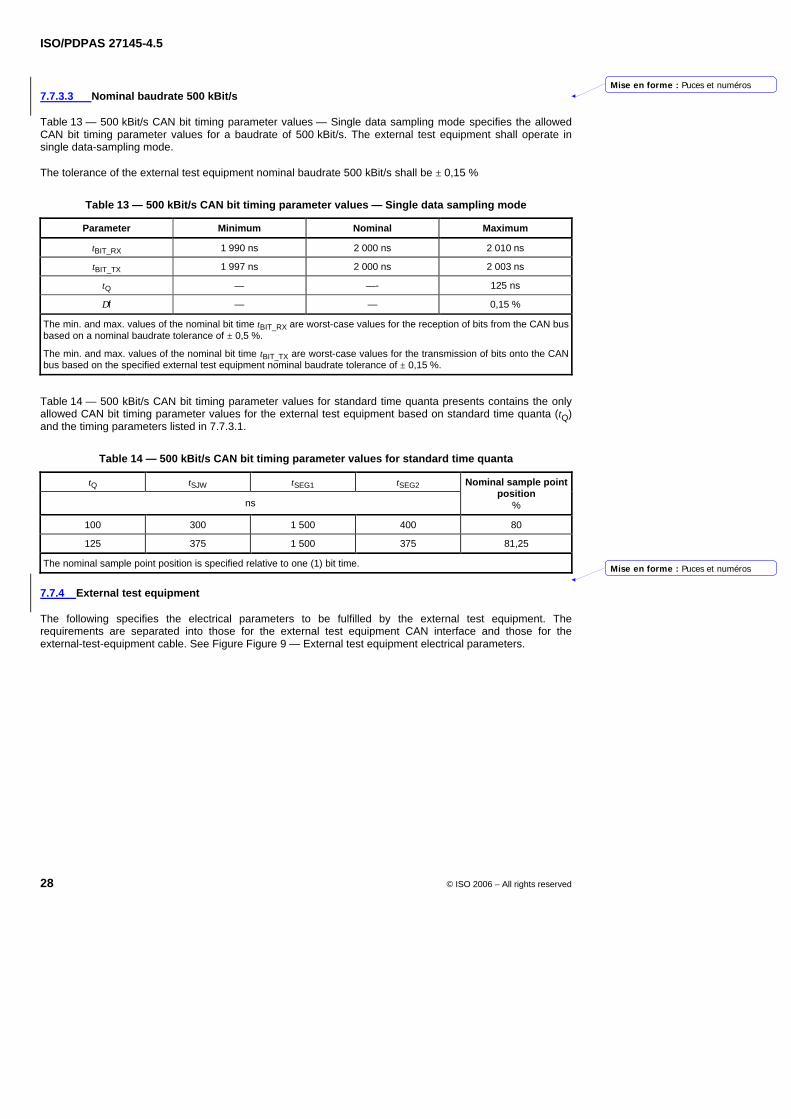
ISO/PDPAS 27145-4.5
28 © ISO 2006 – All rights reserved
7.7.3.3 Nominal baudrate 500 kBit/s
Table 13 — 500 kBit/s CAN bit timing parameter values — Single data sampling mode specifies the allowed CAN bit timing parameter values for a baudrate of 500 kBit/s. The external test equipment shall operate in single data-sampling mode.
The tolerance of the external test equipment nominal baudrate 500 kBit/s shall be ± 0,15 %
Table 13 — 500 kBit/s CAN bit timing parameter values — Single data sampling mode
Parameter Minimum Nominal Maximum
tBIT_RX 1 990 ns 2 000 ns 2 010 ns
tBIT_TX 1 997 ns 2 000 ns 2 003 ns
tQ — —- 125 ns
∆f — — 0,15 %
The min. and max. values of the nominal bit time tBIT_RX are worst-case values for the reception of bits from the CAN bus based on a nominal baudrate tolerance of ± 0,5 %.
The min. and max. values of the nominal bit time tBIT_TX are worst-case values for the transmission of bits onto the CAN bus based on the specified external test equipment nominal baudrate tolerance of ± 0,15 %.
Table 14 — 500 kBit/s CAN bit timing parameter values for standard time quanta presents contains the only allowed CAN bit timing parameter values for the external test equipment based on standard time quanta (tQ) and the timing parameters listed in 7.7.3.1.
Table 14 — 500 kBit/s CAN bit timing parameter values for standard time quanta
tQ tSJW tSEG1 tSEG2
ns
Nominal sample point position
%
100 300 1 500 400 80
125 375 1 500 375 81,25
The nominal sample point position is specified relative to one (1) bit time.
7.7.4 External test equipment
The following specifies the electrical parameters to be fulfilled by the external test equipment. The requirements are separated into those for the external test equipment CAN interface and those for the external-test-equipment cable. See Figure Figure 9 — External test equipment electrical parameters.
Mise en forme : Puces et numéros
Mise en forme : Puces et numéros
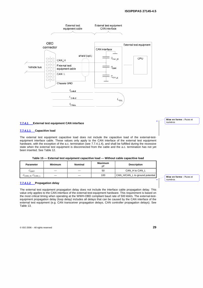
ISO/PDPAS 27145-4.5
© ISO 2006 – All rights reserved 29
Figure 9 — External test equipment electrical parameters
7.7.4.1 External test equipment CAN interface
7.7.4.1.1 Capacitive load
The external test equipment capacitive load does not include the capacitive load of the external-test-equipment interface cable. These values only apply to the CAN interface of the external test equipment hardware, with the exception of the a.c. termination (see 7.7.4.1.4), and shall be fulfilled during the recessive state when the external test equipment is disconnected from the cable and the a.c. termination has not yet been inserted. See Table 12.
Table 15 — External test equipment capacitive load — Without cable capacitive load
Parameter Minimum Nominal Maximum pF
Description
CDIFF — — 50 CAN_H to CAN_L
CCAN_H, CCAN_L — — 100 CAN_H/CAN_L to ground potential
7.7.4.1.2 Propagation delay
The external test equipment propagation delay does not include the interface cable propagation delay. This value only applies to the CAN interface of the external-test-equipment hardware. This requirement is based on the most critical timing when operating at the WWH-OBD compliant baud rate of 500 kbit/s. The external-test-equipment propagation delay (loop delay) includes all delays that can be caused by the CAN interface of the external test equipment (e.g. CAN transceiver propagation delays, CAN controller propagation delays). See Table 13.
Mise en forme : Puces etnuméros
Mise en forme : Puces etnuméros
ISO/PDPAS 27145-4.5
30 © ISO 2006 – All rights reserved
Table 16 — External test equipment propagation delay — Loop delay without cable delay
Parameter Minimum Nominal Maximum ns
Description
tTOOL — — 390 Loop delay of external test equipment
7.7.4.1.3 CAN bus termination
The following sub-clauses specify the termination requirements to be fulfilled by the external test equipment. Two alternative terminations are specified, one a.c. termination (section 7.7.4.1.4) and one d.c. termination (section 7.7.4.1.5) of which either one is allowed.
NOTE For new implementations, the d.c. termination as defined in section 7.7.4.1.5 is recommended.
7.7.4.1.4 A.C. termination
For the a.c. termination alternative, there shall be no termination resistor between the CAN conductors CAN_H and CAN_L in the external test equipment for the adaptation to the physical media impedance. The external test equipment shall be an un-terminated node on the CAN bus to which it is connected (see Figure 10 — External test equipment CAN bus a.c. termination).
2%
'FR
QQHF
WRU
Figure 10 — External test equipment CAN bus a.c. termination
The external test equipment using an a.c. termination for the purpose of minimizing reflections on the CAN bus shall use parameter values for the termination of the network according to Table 17 — External-test-equipment a.c. termination parameters.
Table 17 — External-test-equipment a.c. termination parameters
Parameter Minimum Nominal Maximum Description
R1, R2 90 Ω 100 Ω 110 Ω Resistor of the a.c. termination
C1, C2 470 pF 560 pF 640 pF Capacitor of the a.c. termination
Mise en forme : Puces et numéros
Mise en forme : Puces et numéros
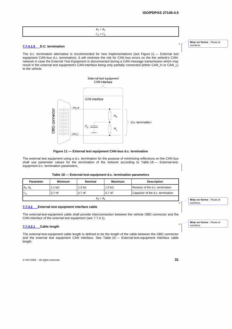
ISO/PDPAS 27145-4.5
© ISO 2006 – All rights reserved 31
R1 = R2
C1 = C2
7.7.4.1.5 D.C. termination
The d.c. termination alternative is recommended for new implementations (see Figure 11 — External test equipment CAN-bus d.c. termination). It will minimize the risk for CAN bus errors on the the vehicle's CAN-network in case the External Test Equipment is disconnected during a CAN message transmission which may result in the external test equipment's CAN-interface being only partially connected (either CAN_H or CAN_L) to the vehicle.
Figure 11 — External test equipment CAN-bus d.c. termination
The external test equipment using a d.c. termination for the purpose of minimizing reflections on the CAN bus shall use parameter values for the termination of the network according to Table 18 — External-test-equipment d.c. termination parameters.
Table 18 — External-test-equipment d.c. termination parameters
Parameter Minimum Nominal Maximum Description
R3, R4 1,1 kΩ 1,3 kΩ 1,5 kΩ Resistor of the d.c. termination
C3 3,7 nF 4,7 nF 5,7 nF Capacitor of the d.c. termination
R3 = R4
7.7.4.2 External test equipment interface cable
The external-test-equipment cable shall provide interconnection between the vehicle OBD connector and the CAN interface of the external test equipment (see 7.7.4.1).
7.7.4.2.1 Cable length
The external-test-equipment cable length is defined to be the length of the cable between the OBD connector and the external test equipment CAN interface. See Table 19 — External-test-equipment interface cable length.
Mise en forme : Puces etnuméros
Mise en forme : Puces etnuméros
Mise en forme : Puces etnuméros
ISO/PDPAS 27145-4.5
32 © ISO 2006 – All rights reserved
Table 19 — External-test-equipment interface cable length
Parameter Minimum Nominal Maximum m
Description
LCABLE — — 5 External-test-equipment cable length
7.7.4.2.2 Propagation delay
The cable propagation delay shall not include the external test equipment propagation delay. This value only applies to the interface cable. This requirement is based on the most critical timing when operating at the baudrate of 500 kbit/s. The cable propagation delay is defined as a one-way delay, from the OBD connector to the external test equipment CAN interface. See Table 20 — External-test-equipment interface cable propagation delay.
Table 20 — External-test-equipment interface cable propagation delay
Parameter Minimum Nominal Maximum ns Description
tCABLE — — 27,5 External-test-equipment cable delay
7.7.4.2.3 Cable configuration requirements
The following configuration requirements apply to the external-test-equipment cable.
No other wires shall be twisted with CAN conductor(s) CAN_H or CAN_L. However, twisting of the CAN conductors with Signal Ground is allowed.
NOTE There are no aditional requirements for twisting.
The CAN_H and CAN_L conductors shall have the same length and traverse the same path for the entire distance.
CAN_H and CAN_L conductors shall not be included in a bundle containing radiating wires which induce more than 0,5 V noise modulation on either CAN conductor relative to Signal Ground.
The cable shall be shielded where the external-test-equipment cable length exceeds 1 m. The shield shall be connected to the chassis ground pin of the cable side of the OBD connector.
Mise en forme : Puces et numéros
Mise en forme : Puces et numéros
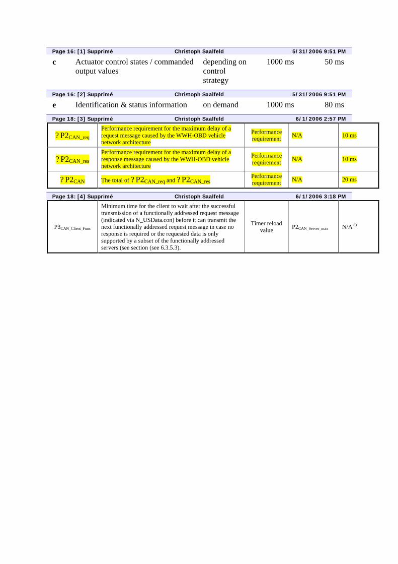
Page 16: [1] Supprimé Christoph Saalfeld 5/31/2006 9:51 PM
c Actuator control states / commanded output values
depending on control strategy
1000 ms 50 ms
Page 16: [2] Supprimé Christoph Saalfeld 5/31/2006 9:51 PM
e Identification & status information on demand 1000 ms 80 ms
Page 18: [3] Supprimé Christoph Saalfeld 6/1/2006 2:57 PM
? P2CAN_req Performance requirement for the maximum delay of a request message caused by the WWH-OBD vehicle network architecture
Performance requirement N/A 10 ms
? P2CAN_res Performance requirement for the maximum delay of a response message caused by the WWH-OBD vehicle network architecture
Performance requirement N/A 10 ms
? P2CAN The total of ? P2CAN_req and ? P2CAN_res Performance requirement N/A 20 ms
Page 18: [4] Supprimé Christoph Saalfeld 6/1/2006 3:18 PM
P3CAN_Client_Func
Minimum time for the client to wait after the successful transmission of a functionally addressed request message (indicated via N_USData.con) before it can transmit the next functionally addressed request message in case no response is required or the requested data is only supported by a subset of the functionally addressed servers (see section (see 6.3.5.3).
Timer reload value P2CAN_Server_max N/A d)