contents byte precabling solution - home | controller ... · contents byte precabling solution byte...
TRANSCRIPT
Byt
e P
reca
blin
g S
olu
tio
n
C
C.1
Contents
Byte Precabling Solution
Byte Precabling System C.2
Selection Guide C.4
PLC Front Adapter for SIEMENS S7 C.7
PLC Input/Output Module Passive C.10
PLC Input/Output Module Active C.16
Adapter and Solution for MICROSERIES Relays and Optocouplers C.21
Relays – MICROSERIES C.24
Optos – MICROSERIES C.27
Universal Cables C.31
Accessories C.34
Byte Precabling Solution

Byt
e P
reca
blin
g S
olu
tio
n
C
C.2
Byte Precabling System
This system allows the user to design a byte wiring system fordigital inputs as well as outputs.It is possible to connect the inputs and outputs either directly byusing an 8-channel wiring interface or interface them with relaysand optocouplers.In this case, individual modules from the MICROseries family areused which are directly assembled in groups of 8 and connectedby cable to the PLC using an adapter fitted with a 10-pole HE10 female connector.You can thus use different power supplies on each of the 8 channels.
• Screw or tension clamp connection • Very compact modules• Clear and accurate labelling
Block of eight MICROseries modulesfor interfacing through relay or optocoupler
Digital MICROinterface adapter
Wiring interface module for direct connection to the PLC
Cable for Siemens S7-300 PLC with front adapter
Cable for Télémécanique Micro and Premium PLCs
PLC connector
Byte precabling system

Byt
e P
reca
blin
g S
olu
tio
n
C
C.3
Byte Precabling System
PLC system interface
Wiring and circuitry is becoming increasingly complicated as a result of the growing complexity of machines and systems in process, automation and building services control systems. Conventional connections (point-to-point wiring) between PLC controllers and peripheral devices result in high installation and commissioning cost. The Weidmuller range of PLC system interface products provides the user with a quickly and easily installed output level for SIEMENS SIMATIC® S7.
The specific front adapters replace the usual screw terminal technology used on the PLC input/output cards. 40- or 10-poleconnectors transfer the PLC signals to the active or passive components via pre-assembled control leads.
The PLC signals are converted either• in double word mode to a 40-pole ribbon cable connector,
or• in byte mode to 4 ribbon cable connectors each with 10 poles.PLC I/O cards usually have two connection systems:• screw clamp• crimp connectorsIn both cases, the signals have to be wired individually with thecorresponding connection elements.
Disadvantages of individual wiring:• High assembly cost• The risk of wiring mistakes increases with the number of
individual wires at one point• Requires considerable space in the switchboard• High installation workload• Time-consuming routing and assembly of connecting leads• High labelling and documentation workload
System advantages
• Fast– Reduced planning and design time– Time-saving installation– Less time required for commissioning and troubleshooting– Minimized wiring effort on site thanks to plug-type connectors
• Safe– Rules out the risk of wiring mistakes– Clear organization in the switchboard (system cable instead
of individual wires)– Marking corresponds with PLC– Additional individual marking
• Variable– Multitude of about 40 different I/O components– Variable cable lengths– Modular design of all components– 1 x 4 byte and 4 x 1 byte system designs without signal
routing module– Functions mixed by byte to an input or output level– Expansion possible without difficulty– Flexibility due to simple swapping of input/output interfaces
• Small– Saves space in cable ducts– Small module widths– No terminal levels
Use of PLC front adapters

C.4
Byt
e P
reca
blin
g S
olu
tio
n
C
PLC Siemens - S7-300
Selection Guide
PLC connector
Cable 843331xxxxBlock of 8 MICROseries modules
Cable 7789235xxx
* Note: It is possible to replace these standard relay modules with the “ACT” version which provides a non-wired common.• MRS 24Vdc ACT 8660920000 (screw connection) instead of 8533640000• MRZ 24Vdc ACT 8660910000 (tension clamp connection) instead of 8533660000
Dig
ital
inp
utD
igit
al o
utp
ut
6ES7 321-1BH01-0AA0
6ES7 321-1BH81-0AA0
6ES7 321-1BL00-0AA0
7789235xxx 2
2
4
4
2
2
2
2
4
C.25
C.25
C.25
C.25
C.25
C.25
C.25
C.25
C.25
C.27
C.27
C.27
C.27
C.27
C.27
C.29
C.29
C.29
C.23
C.23
C.23
C.23
C.23
C.23
C.23
C.23
C.23
16
16
32
32
16
16
16
16
32
16
16
32
32
16
16
16
16
32
2
2
4
4
2
2
2
2
4
7789235xxx
843331xxxx
1
1
1
6ES7 321-1BL80-0AA0
6ES7 321-1BH50-0AA0
6ES7 321-7RD00-0AB0
843331xxxx
7789235xxx
7789235xxx
1
1
1
6ES7 322-1BH01-0AA0
6ES7 322-1BH81-0AA0
6ES7 322-1BL00-0AA0
7789235xxx
7789235xxx
843331xxxx
1
1
1
8248050000
8428870000
8248050000
8428870000
8248050000
8428870000
8248050000
8428870000
8248050000
8428870000
8248050000
8428870000
8248050000
8428870000
8248050000
8428870000
8248050000
8428870000
Z
Z
Z
Z
Z
Z
Z
Z
Z
V
V
V
V
V
V
V
V
V
Manufacturer order numbers Order No.Order No.
I/O cards
PLC Cables Interfaces
StandardOption 1 Option 2: adapter + relay or optocoupler as desired
Direct inputs or outputs Inputs or outputs with relay
Inputs or outputswith optocoupler
Qty
Connection
Screw Tension c. Qty Page Order No. Qty Page
8556060000
8556080000
8556060000
8556080000
8556060000
8556080000
8556060000
8556080000
8556060000
8556080000
8556060000
8556080000
8533640000*
8533660000*
8533640000*
8533660000*
8533640000*
8533660000*
Order No. Qty Page
8607340000
8607360000
8607340000
8607360000
8607340000
8607360000
8607340000
8607360000
8607340000
8607360000
8607340000
8607360000
8607350000
8607370000
8607350000
8607370000
8607350000
8607370000
Order No. Qty Page
Adapter
8773510000
8773530000
8773510000
8773530000
8773510000
8773530000
8773510000
8773530000
8773510000
8773530000
8773510000
8773530000
8773600000
8773620000
8773600000
8773620000
8773600000
8773620000
C.12
C.11
C.12
C.11
C.12
C.11
C.12
C.11
C.12
C.11
C.12
C.11
C.12
C.11
C.12
C.11
C.12
C.11

C.5
Byt
e P
reca
blin
g S
olu
tio
n
C
PLC Siemens - S7-400
Selection Guide
Cable 833591xxxxBlock of 8 MICROseries modules
* Note: It is possible to replace these standard relay modules with the “ACT” version which provides a non-wired common.• MRS 24Vdc ACT 8660920000 (screw connection) instead of 8533640000• MRZ 24Vdc ACT 8660910000 (tension clamp connection) instead of 8533660000
ES
6ES7 421-1BL00-0AA0
6ES7 422-1BL00-0AA0
6ES7 422-7BL00-0AB0
833591xxxx
833591xxxx
833591xxxx
1
1
1
8248050000
8428870000
8248050000
8428870000
8248050000
8428870000
Z
Z
Z
V
V
V
Manufacturer order numbers Order No.Order No.
I/O cards
PLC Cables Interfaces
StandardOption 1 Option 2: adapter + relay or optocoupler as desired
Direct inputs or outputs
Inputs or outputswith relay
Inputs or outputswith optocoupler
Qty
Connection
Screw Tension c. Qty Page Order No. Qty Page
8556060000
8556080000
8533640000*
8533660000*
8533640000*
8533660000*
Order No. Qty Page
8607340000
8607360000
8607350000
8607370000
8607350000
8607370000
Order No. Qty Page
Adapter
8773510000
8773530000
8773600000
8773620000
8773600000
8773620000
4
4
4
4
4
4
32
32
32
32
32
32
C.23
C.23
C.23
C.25
C.25
C.25
C.27
C.29
C.29
C.12
C.11
C.12
C.11
C.12
C.11

C.6
Byt
e P
reca
blin
g S
olu
tio
n
C
PLC Télémécanique - Premium/Micro
Selection Guide
PLC connector
Cable 7789303xxxBlock of 8 MICROseries modules
* Note: It is possible to replace these standard relay modules with the “ACT” version which provides a non-wired common.• MRS 24Vdc ACT 8660920000 (screw connection) instead of 8533640000• MRZ 24Vdc ACT 8660910000 (tension clamp connection) instead of 8533660000
Input
OutputTSX DMZ 64DTK
TSX DEY 16FK
TSX DEY 32D2K
TSX DEY 64D2K
TSX DSY 32T2K
TSX DSY 64T2K
7789303xxx
7789303xxx
7789303xxx
7789303xxx
7789303xxx
7789303xxx
4
1
2
4
2
4
8248050000
8428870000
8248050000
8428870000
8248050000
8428870000
8248050000
8428870000
8248050000
8428870000
8248050000
8428870000
8248050000
8428870000
Z
Z
Z
Z
Z
Z
Z
V
V
V
V
V
V
V
Digi
tal o
utpu
tD
igit
al in
put
Dig
ital I
/O
Manufacturer order numbers Order No.Order No.
I/O cards
PLC Cables Interfaces
StandardOption 1 Option 2: adapter + relay or optocoupler as desired
Direct inputs or outputs
Inputs or outputswith relay
Inputs or outputswith optocoupler
Qty TypeScrew Tension c. Qty Page Order No. Qty Page
8596060000
8596080000
8533640000
8533660000
8596060000
8596080000
8596060000
8596080000
8596060000
8596080000
8533640000*
8533660000*
8533640000*
8533660000*
Order No. Qty Page
8607340000
8607360000
8607350000
8607370000
8607340000
8607360000
8607340000
8607360000
8607340000
8607360000
8607350000
8607370000
8607350000
8607370000
Order No. Qty Page
Adapter
8773510000
8773530000
8773600000
8773620000
8773510000
8773530000
8773510000
8773530000
8773510000
8773530000
8773600000
8773620000
8773600000
8773620000
Connection
4
4
2
4
8
4
8
4
4
2
4
8
4
8
C.27
C.27
C.27
C.27
C.27
C.29
C.29
C.25
C.25
C.25
C.25
C.25
C.25
C.25
C.23
C.23
C.23
C.23
C.23
C.23
C.23
32
32
16
32
64
32
64
32
32
16
32
64
32
64
C.12
C.11
C.12
C.11
C.12
C.11
C.12
C.11
C.12
C.11
C.12
C.11
C.12
C.11
C.7
Byt
e P
reca
blin
g S
olu
tio
n
C
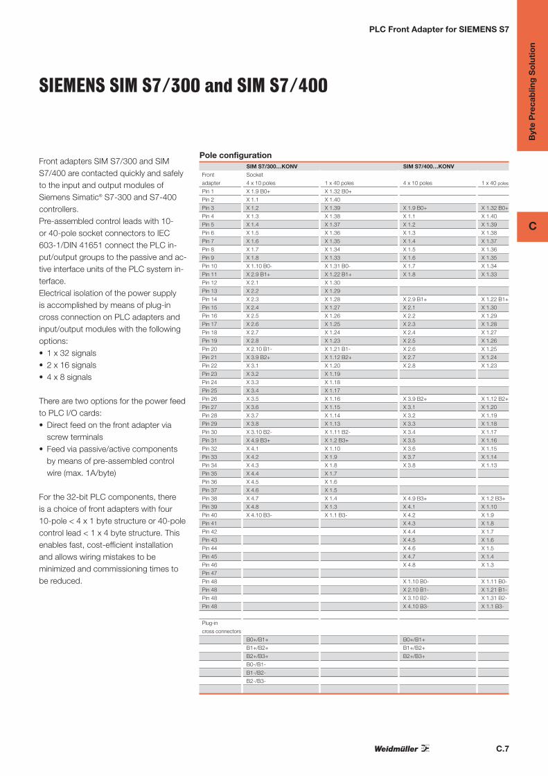
PLC Front Adapter for SIEMENS S7
Front adapters SIM S7/300 and SIMS7/400 are contacted quickly and safelyto the input and output modules of Siemens Simatic® S7-300 and S7-400 controllers.Pre-assembled control leads with 10- or 40-pole socket connectors to IEC603-1/DIN 41651 connect the PLC in-put/output groups to the passive and ac-tive interface units of the PLC system in-terface.Electrical isolation of the power supply is accomplished by means of plug-incross connection on PLC adapters andinput/output modules with the followingoptions:• 1 x 32 signals• 2 x 16 signals• 4 x 8 signals
There are two options for the power feedto PLC I/O cards:• Direct feed on the front adapter via
screw terminals• Feed via passive/active components
by means of pre-assembled controlwire (max. 1A/byte)
For the 32-bit PLC components, there is a choice of front adapters with four10-pole < 4 x 1 byte structure or 40-polecontrol lead < 1 x 4 byte structure. Thisenables fast, cost-efficient installationand allows wiring mistakes to be minimized and commissioning times tobe reduced.
Pole configurationSIM S7/300…KONV SIM S7/400…KONV
Front Socket
adapter 4 x 10 poles 1 x 40 poles 4 x 10 poles 1 x 40 poles
Pin 1 X 1.9 B0+ X 1.32 B0+
Pin 2 X 1.1 X 1.40
Pin 3 X 1.2 X 1.39 X 1.9 B0+ X 1.32 B0+
Pin 4 X 1.3 X 1.38 X 1.1 X 1.40
Pin 5 X 1.4 X 1.37 X 1.2 X 1.39
Pin 6 X 1.5 X 1.36 X 1.3 X 1.38
Pin 7 X 1.6 X 1.35 X 1.4 X 1.37
Pin 8 X 1.7 X 1.34 X 1.5 X 1.36
Pin 9 X 1.8 X 1.33 X 1.6 X 1.35
Pin 10 X 1.10 B0- X 1.31 B0- X 1.7 X 1.34
Pin 11 X 2.9 B1+ X 1.22 B1+ X 1.8 X 1.33
Pin 12 X 2.1 X 1.30
Pin 13 X 2.2 X 1.29
Pin 14 X 2.3 X 1.28 X 2.9 B1+ X 1.22 B1+
Pin 15 X 2.4 X 1.27 X 2.1 X 1.30
Pin 16 X 2.5 X 1.26 X 2.2 X 1.29
Pin 17 X 2.6 X 1.25 X 2.3 X 1.28
Pin 18 X 2.7 X 1.24 X 2.4 X 1.27
Pin 19 X 2.8 X 1.23 X 2.5 X 1.26
Pin 20 X 2.10 B1- X 1.21 B1- X 2.6 X 1.25
Pin 21 X 3.9 B2+ X 1.12 B2+ X 2.7 X 1.24
Pin 22 X 3.1 X 1.20 X 2.8 X 1.23
Pin 23 X 3.2 X 1.19
Pin 24 X 3.3 X 1.18
Pin 25 X 3.4 X 1.17
Pin 26 X 3.5 X 1.16 X 3.9 B2+ X 1.12 B2+
Pin 27 X 3.6 X 1.15 X 3.1 X 1.20
Pin 28 X 3.7 X 1.14 X 3.2 X 1.19
Pin 29 X 3.8 X 1.13 X 3.3 X 1.18
Pin 30 X 3.10 B2- X 1.11 B2- X 3.4 X 1.17
Pin 31 X 4.9 B3+ X 1.2 B3+ X 3.5 X 1.16
Pin 32 X 4.1 X 1.10 X 3.6 X 1.15
Pin 33 X 4.2 X 1.9 X 3.7 X 1.14
Pin 34 X 4.3 X 1.8 X 3.8 X 1.13
Pin 35 X 4.4 X 1.7
Pin 36 X 4.5 X 1.6
Pin 37 X 4.6 X 1.5
Pin 38 X 4.7 X 1.4 X 4.9 B3+ X 1.2 B3+
Pin 39 X 4.8 X 1.3 X 4.1 X 1.10
Pin 40 X 4.10 B3- X 1.1 B3- X 4.2 X 1.9
Pin 41 X 4.3 X 1.8
Pin 42 X 4.4 X 1.7
Pin 43 X 4.5 X 1.6
Pin 44 X 4.6 X 1.5
Pin 45 X 4.7 X 1.4
Pin 46 X 4.8 X 1.3
Pin 47
Pin 48 X 1.10 B0- X 1.11 B0-
Pin 48 X 2.10 B1- X 1.21 B1-
Pin 48 X 3.10 B2- X 1.31 B2-
Pin 48 X 4.10 B3- X 1.1 B3-
Plug-in
cross connectors
B0+/B1+ B0+/B1+
B1+/B2+ B1+/B2+
B2+/B3+ B2+/B3+
B0-/B1-
B1-/B2-
B2-/B3-
SIEMENS SIM S7/300 and SIM S7/400

C.8
Byt
e P
reca
blin
g S
olu
tio
n
C
PLC front adapter for SIEMENS S7
• Pre-assembled control cable
• Control cable 1x40- or 4x10 pole in 4 standardlengths
• Separate feeding of the supply voltage via screwconnection terminals
• Outstanding cross connectability using ZQVsystem
• Versatile accessories
• Inexpensive coupling of the interface modules
Front adapter for SIEMENS S7 300 E/A-mod-ules
Digital input:
S7/300 6ES7 321-1BL00-0AA0, 32DI
Digital output :
S7/300 6ES7 322-1BL00-0AA0, 32DO
Digital input/output:
S7/300 6ES7 323-1BL00-0AA0, 16DI/16DO
Technical dataConnection data
Connection on process side g
Type of connection sembled cable with IEC603/1 plug-in con-
nector
Design ole pre-assembled cable with 10-pole female connec-
tor
Configuration of single conductor
Connection system, supply voltage/other connections
Rated data
Number of signals
Rated voltage DC
Rated current per connection
Current-carrying capacity/ cable 10-pole/Line, 40-pole
Voltage supply/Byte discon.
Total current feed, max.
Dimensions
Clamping range (rating- / min. / max.) mm2
Length x width x height mm
Note
Ordering data
2 m control line
2.5 m control line
3 m control line
5 m control line
Note
PLC Front Adapter for SIEMENS S7
SIEMENS S7/300 1 x 4 Byte
Simatic S7/300 1x4 Byte
X 1
X 3 X 4 X 1
X 2
Connection data
SIEMENS front panel housing
1x40-pole pre-assembled cable with IEC603/1 plug-in con-
nector or
1x40-pole pre-assembled cable with female connector nnec-
tor
7-core control line AWG 26/7 ctor
PCB screw connection terminals ge/other connections
Rated data
32 / 1x4 byte als
60 V AC/ 75 V DC
1 A ed current per connection
/26 A/ dT = 20 K capacity/ cable 10-pole/Line, 40-pole
yes age supply/Byte discon.
16 A l current feed, max.
115 x 22 x 32
Type Qty. Order No.
SIM S7/300 FB40 2.0M 1 8433290200
SIM S7/300 FB40 2.5M 1 8433290250
SIM S7/300 FB40 3.0M 1 8433290300
SIM S7/300 FB40 5.0M 1 8433290500
SIEMENS S7/300 4 x 1 Byte
Simatic S7/300 4x1Byte
X 1
X 3 X 4 X 1
X 2
Connection data
SIEMENS front panel housing
4 x 10-pole pre-assembled cable with IEC603/1 plug-in con-
nector
4x10-pole pre-assembled cable with 10-pole female connec-
tor
7-core control line AWG 26/7 ctor
PCB screw connection terminals ge/other connections
Rated data
32 / 4x1 byte als
60 V AC/ 75 V DC
1 A ed current per connection
11.5 A/ dT = 20 K / pacity/ cable 10-pole/Line, 40-pole
yes age supply/Byte discon.
16 A l current feed, max.
115 x 22 x 32
Type Qty. Order No.
SIM S7/300 FB4*10 2.0M 1 8433310200
SIM S7/300 FB4*10 2.5M 1 8433310250
SIM S7/300 FB4*10 3.0M 1 8433310300
SIM S7/300 FB4*10 5.0M 1 8433310500

C.9
Byt
e P
reca
blin
g S
olu
tio
n
C
PLC front adapter for SIEMENS S7
• Pre-assembled control cable
• 1x40-pole or 4x10-pole cables in 4 standardlengths
• Separate feeding of supply voltage via screwconnection terminals
• Outstanding cross connectability using ZQVsystem
• Versatile system accessories
• Inexpensive coupling of interface modules
Front adapter for SIEMENS S7 400 I/O mod-ules
Digital input:
S7/400 6ES7 421-1BL00-0AA0, 32DI
Digital output:
S7/400 6ES7 422-1BL00-0AA0, 32DO
Technical dataConnection data
Connection on process side g
Type of connection sembled cable with IEC603/1 plug-in con-
nector
Design ole pre-assembled cable with 10-pole female connec-
tor
Configuration of single conductor
Connection system, supply voltage/other connections
Rated data
Number of signals
Rated voltage DC
Rated current per connection
Current-carrying capacity/ cable 10-pole/Line, 40-pole
Voltage supply/Byte discon.
Total current feed, max.
Dimensions
Clamping range (rating- / min. / max.) mm2
Length x width x height mm
Note
Ordering data
2 m control line
2.5 m control line
3 m control line
5 m control line
Note
PLC Front Adapter for SIEMENS S7
SIEMENS S7/400 1x 4 Byte
Simatic S7/400 1x4Byte
X 1
X 3 X 4 X 1
X 2
Connection data
SIEMENS front panel housing
1x40-pole pre-assembled cable with IEC603/1 plug-in con-
nector or
1x40-pole pre-assembled cable with female connector nnec-
tor
7-core control line AWG 26/7 ctor
PCB screw connection terminals ge/other connections
Rated data
32 / 1x4 byte als
60 V AC/ 75 V DC
1 A ed current per connection
/26 A/ dT = 20 K capacity/ cable 10-pole/Line, 40-pole
yes age supply/Byte discon.
16 A l current feed, max.
274 x 19 x 55
Type Qty. Order No.
SIM S7/400 FB40 2.0M 1 8335900200
SIM S7/400 FB40 2.5M 1 8335900250
SIM S7/400 FB40 3.0M 1 8335900300
SIM S7/400 FB40 5.0M 1 8335900500
SIEMENS S7/400 4 x 1 Byte
Simatic S7/400 4x1Byte
X 1
X 3 X 4 X 1
X 2
Connection data
SIEMENS front panel housing
4 x 10-pole pre-assembled cable with IEC603/1 plug-in con-
nector
4x10-pole pre-assembled cable with 10-pole female connec-
tor
7-core control line AWG 26/7 ctor
PCB screw connection terminals ge/other connections
Rated data
32 / 4x1 byte als
60 V AC/ 75 V DC
1 A ed current per connection
11.5 A/ dT = 20 K / pacity/ cable 10-pole/Line, 40-pole
yes age supply/Byte discon.
16 A l current feed, max.
274 x 19 x 55
Type Qty. Order No.
SIM S7/400 FB4*10 2.0M 1 8335910200
SIM S7/400 FB4*10 2.5M 1 8335910250
SIM S7/400 FB4*10 3.0M 1 8335910300
SIM S7/400 FB4*10 5.0M 1 8335910500

C.10
Byt
e P
reca
blin
g S
olu
tio
n
C
Passive components
PLC Input/Output Module Passive
The RSF40 or RS F10 passive interface units for 32 or 8 signals allow for efficient connection of peripheral initiators, sensors and actuators to PLC input/output modules. The linkbetween the PLC and the interface module consists of the controller-specific front adapter and the pre-assembled controllead. This wiring version replaces point-to-point wiring, which isprone to mistakes and is costly to install. The necessary auxiliary voltage is provided at the connection units. An optional status indicator (LED) shows the switching state and the operating voltages.
Input/output module RS 45 profile designed for
• 1:1 signal transfer of 32 or 8 signals to PLC input/output modules,
• connection of RS F40 LPK2 and RS F10 LPK2 two-wire andthree-wire sensors/initiators to PLC input/output modules.
Features• Choice of screw or tension clamp terminal• RS45 modules with extremely narrow width of 45 mm• 32x module via plug-in jumpers in sensor groups
(1 x 32, 2 x 16 or 4 x 8 signals)• Signals grouped by byte• Test point on the board through connection element• Clearly organized terminal marking• Additional labelling panel for group identification• Clips to TS35 DIN rail (RS 45 profile) in 45 mm width and
TS 32/35 DIN rail in 87 mm width
Individual wiring

C.11
Byt
e P
reca
blin
g S
olu
tio
n
C
Input/Output in single-conductorsystem
• Compact design
• Tension clamp connection system
• Clear connection type
• Clips to TS 35
Technical dataConnection data
Connection on process side
Stripping length
Connection system, supply voltage/other connections
Coupling on control side, 8- way module
Coupling on control side, 32- way module
Rated data
Number of signals
Rated voltage DC
Rated current per connection
Common potential at terminal/Voltage supply/Byte discon.
Ambient temperature (operational)/Storage temperature
Surge category/Pollution severity
Terminal rail
Dimensions
Clamping range (rating- / min. / max.) mm2
Length x width x height mm
Note
Ordering data
Note
PLC Input/Output Module Passive
RS F10 I/O8 LMZF
I/O module
123456789
10
X 1.0.1
.3
.5
.7
.L-
Connection data
PCB terminal LMZF ess side
7.0 mm ing length
Tension clamp connection terminal other connections
10-pole FB-socket IEC 603-1 - way module
Coupling on control side, 32- way module
Rated data
8 / 1x1 byte nals
60 V AC/ 75 V DC
1 A ed current per connection
/ ommon potential at terminal/Voltage supply/Byte discon.
0 °C…+55 °C /-40 °C…+70 °C l)/Storage temperature
II /2 category/Pollution severity
TS 35 nal rail
1.5 / 0.5 / 2.5
45 x 43 x 54
Type Qty. Order No.
RS F10 I/O8 LMZF 1 8428870000
RS F40 I/O32 LMZF
I/O module
40393837
3534
3231
2928
2625
2322
2019
1716
1413
1110987654321
X 10.00.10.20.30.40.50.6
0.L+0.L-
1.11.2
1.41.5
1.71.L+
2.02.1
2.32.4
2.62.72.L+1.L-3.03.13.23.33.43.53.63.73.L+3.L-
Connection data
PCB terminal LMZF ess side
7.0 mm ing length
Tension clamp connection terminal other connections
Coupling on control side, 8- way module
40-pole FB-socket IEC 603-1 2- way module
Rated data
32 / 1x4 byte als
60 V AC/ 75 V DC
1 A ed current per connection
/no on potential at terminal/Voltage supply/Byte discon.
0 °C…+55 °C /-40 °C…+70 °C l)/Storage temperature
II /2 category/Pollution severity
TS 35 nal rail
1.5 / 0.5 / 2.5
45 x 125 x 54
Type Qty. Order No.
RS F40 I/O32 LMZF 1 8428880000

C.12
Byt
e P
reca
blin
g S
olu
tio
n
C
Input/Output in single-conductorsystem
• Compact design
• Screw connection system
• Clear connection type
• Clips to TS 35
Technical dataConnection data
Connection on process side
Stripping length
Connection system, supply voltage/other connections
Coupling on control side, 8- way module
Coupling on control side, 32- way module
Rated data
Number of signals
Rated voltage DC
Rated current per connection
Common potential at terminal/Voltage supply/Byte discon.
Ambient temperature (operational)/Storage temperature
Surge category/Pollution severity
Terminal rail
Dimensions
Clamping range (rating- / min. / max.) mm2
Length x width x height mm
Note
Ordering data
Note
PLC Input/Output Module Passive
RS F10 LPK 2H/12
I/O module
.0X 1
X 2
.1
1
2
.2
.3
3
4
.4
.5
5
6
.6
.7
7
8
+
-
9
10
P
P
Connection data
PCB terminal LPK 2 H side
7.0 mm ing length
Screw connection , supply voltage/other connections
10-pole FB-socket IEC 603-1 - way module
Coupling on control side, 32- way module
Rated data
8 / 1x1 byte nals
60 V AC/ 75 V DC
1 A ed current per connection
/- mon potential at terminal/Voltage supply/Byte discon.
0 °C…+55 °C /-40 °C…+70 °C l)/Storage temperature
II /2 category/Pollution severity
TS 35 nal rail
1.5 / 0.5 / 2.5
45 x 49 x 65.5
Type Qty. Order No.
RS F10 LPK 2H/12 1 8248050000
RS F40 LPK 2H/42
I/O module
3 L-X 1
3 L+1
3.73
2 L-2 L+
11
12
131415
2.7
2.62.5
1 L-1 L+
21
22
232425
1.7
1.61.5
0 L-0 L+
31
32
333435
0.10.0
39
40
0.7
0.60.5
X 2 PP
.
....
......
......
......
Connection data
PCB terminal LPK 2 H side
7.0 mm ing length
Screw connection , supply voltage/other connections
Coupling on control side, 8- way module
40-pole FB-socket IEC 603-1 2- way module
Rated data
32 / 1x4 byte als
60 V AC/ 75 V DC
1 A ed current per connection
/no on potential at terminal/Voltage supply/Byte discon.
0 °C…+55 °C /-40 °C…+70 °C l)/Storage temperature
II /2 category/Pollution severity
TS 35 nal rail
1.5 / 0.5 / 2.5
45 x 121 x 65.5
Type Qty. Order No.
RS F40 LPK 2H/42 1 8248060000

C.13
Byt
e P
reca
blin
g S
olu
tio
n
C
Input/Output in single-conductorsystem
• Screw connection system
• Clear connection type
• Optional status indicator
• Additional labelling panel for group type
• Clips to TS 32/35
Technical dataConnection data
Connection on process side
Stripping length
Connection system, supply voltage/other connections
Coupling on control side, 8- way module
Rated data
Number of signals
Rated voltage mn;20 %
Rated current per connection
LED current mA
Ambient temperature (operational)/Storage temperature
Surge category/Pollution severity
Terminal rail
Dimensions
Clamping range (rating- / min. / max.) mm2
Length x width x height mm
Note
Ordering data
Note
PLC Input/Output Module Passive
RS F10 I/O8 LPK2
I/O module
.0 1X 1
.1 2
.7 8
+ 9
- 10
.
.
....
Connection data
PCB terminal LPK 2 H side
7.0 mm ing length
Screw connection , supply voltage/other connections
10-pole FB-socket IEC 603-1 - way module
Rated data
8 / 1x1 byte nals
60 V AC/ 75 V DC 0 %
1 A ed current per connection
&lt; 5 mA
0 °C…+55 °C /-40 °C…+70 °C l)/Storage temperature
II /2 category/Pollution severity
TS 32, TS 35 l
1.5 / 0.5 / 2.5
87 x 40 x 80
Type Qty. Order No.
RS F10 I/O8 LPK2 1 8224290000
RS F10 I/O8 LD LPK2
I/O module
.0 1X 1
.1 2
.7 8
+ 9+
--
10
.
.
....
Connection data
PCB terminal LPK 2 H side
7.0 mm ing length
Screw connection , supply voltage/other connections
10-pole FB-socket IEC 603-1 - way module
Rated data
8 / 1x1 byte nals
24 V DC ±20 %
1 A ed current per connection
< 5 mA
0 °C…+55 °C /-40 °C…+70 °C l)/Storage temperature
II /2 category/Pollution severity
TS 32, TS 35 l
1.5 / 0.5 / 2.5
87 x 40 x 80
Type Qty. Order No.
RS F10 I/O8 LD LPK2 1 8224260000

C.14
Byt
e P
reca
blin
g S
olu
tio
n
C
Input module in 3-conductor system
• Tension clamp connection system
• Connection of 3-wire initiators
• Optional status indicator
• Additional labelling panel for group type
• Clips to TS 32/35
Technical dataConnection data
Connection on process side
Stripping length
Connection system, supply voltage/other connections
Coupling on control side, 8- way module e
Rated data
Number of signals
Rated voltage mn;20 %
Rated current per connection
LED current mA
Common potential at terminal/Voltage supply/Byte discon.
Ambient temperature (operational)/Storage temperature
Surge category/Pollution severity
Terminal rail
Dimensions
Clamping range (rating- / min. / max.) mm2
Length x width x height mm
Note
Ordering data
Note
PLC Input/Output Module Passive
RS F10 INIT8 LD LMZF
Input module
1
2
3
4
5
6
7
8
9
.0
.1
.2
.3
.4
.5
.6
.7
L-
10
L+
L+
L-
L-L+
L-L+
L-L+
L-L+
L-L+
L-L+
X 1
Connection data
PCB terminal LMZF ess side
7.0 mm ing length
Tension clamp connection terminal /other connections
10-pole FB-socket IEC 603-1 2- way module
Rated data
8 / 1x1 byte nals
24 V DC ±20 %
1 A ed current per connection
< 5 mA
+/- potential /- at terminal/Voltage supply/Byte discon.
0 °C…+55 °C /-40 °C…+70 °C l)/Storage temperature
II /2 category/Pollution severity
TS 32, TS 35 l
1.5 / 0.5 / 2.5
87 x 54 x 73
Type Qty. Order No.
RS F10 INIT8 LD LMZF 1 8428890000

C.15
Byt
e P
reca
blin
g S
olu
tio
n
C
Input module in 3-conductor system
• Tension clamp connection system
• Connection of 3-wire initiators
• Wire jumpers on the 32-way modules enablegroup-type splitting of the initiators into 1x32,2x16 or 4x8 signals
• Clear byte-by-byte grouping of signals
• Optional status indicator
• Additional labelling panel for group type
• Clips to TS 32/35
Technical dataConnection data
Connection on process side
Stripping length
Connection system, supply voltage/other connections
Coupling on control side, 32- way module
Rated data
Number of signals
Rated voltage mn;20 %
Rated current per connection
LED current mA
Common potential at terminal/Voltage supply/Byte discon.
Ambient temperature (operational)/Storage temperature
Surge category/Pollution severity
Terminal rail
Dimensions
Clamping range (rating- / min. / max.) mm2
Length x width x height mm
Note
Ordering data
Note
PLC Input/Output Module Passive
RS F40 INIT32 LMZF
Input module
32
31
21
3029
22
Connection data
PCB terminal LMZF ess side
7.0 mm ing length
Tension clamp connection terminal /other connections
40-pole FB-socket IEC 603-1 2- way module
Rated data
32 / 1x4 byte als
60 V AC/ 75 V DC 0 %
1 A ed current per connection
&lt; 5 mA
+/- potential /yes terminal/Voltage supply/Byte discon.
0 °C…+55 °C /-40 °C…+70 °C l)/Storage temperature
II /2 category/Pollution severity
TS 32, TS 35 l
1.5 / 0.5 / 2.5
87 x 185 x 73
Type Qty. Order No.
RS F40 INIT32 LMZF 1 8430980000
RS F40 INIT32 LD LMZF
Input module
32
31
21
3029
22
Connection data
PCB terminal LMZF ess side
7.0 mm ing length
Tension clamp connection terminal /other connections
40-pole FB-socket IEC 603-1 2- way module
Rated data
32 / 1x4 byte als
24 V DC ±20 %
1 A ed current per connection
< 5 mA
+/- potential /yes terminal/Voltage supply/Byte discon.
0 °C…+55 °C /-40 °C…+70 °C l)/Storage temperature
II /2 category/Pollution severity
TS 32, TS 35 l
1.5 / 0.5 / 2.5
87 x 185 x 73
Type Qty. Order No.
RS F40 INIT32 LD LMZF 1 8428900000

C.16
Byt
e P
reca
blin
g S
olu
tio
n
C
Active components
PLC Input/Output Module Active
Relay output modules allow transmission of electric signals be-tween PLC controller and the actuator level. A signal isolatorguarantees transmission free of reference potential and decoupling of the electric signals.
Relay output modules for controlling actuators free from reference potential from a PLC.
• RS F40 16 RS for output of 16 signals (with expansion module max. 32 signals),
• RS F40 LMZF 32 RS for output of 32 signals,• RS F10 8RS for output of 8 signals.
The advantages of active interface components:
- low-disturbance and noise-free signal transmission- power gain- compact design- cost- and time-saving wiring with pre-assembled lines- screw or tension spring connections as required- inexpensive adaptation via pre-assembled control lines to
the PLC- electrical isolation of input and output circuits- expansion board for upgrading a 16-way module to a 32-way
module- plug-in relay- integral switching status indicator- labelling panel for group type- can be clipped to TS 32/35

C.17
Byt
e P
reca
blin
g S
olu
tio
n
C
Relays
• Screw connection system
• Base and expansion modules each equippedwith 16 relays
• Plug-in relays with changeover contact
• Expansion module connected via 20-pole ribboncable
• Electrical isolation of input and output circuits
• LED status indicator
• For mounting on TS 32/35
Technical dataConnection data
Number of signals
Connection on process side
Type of connection tor IEC 603/1
Connection system, supply voltage/other connections
Stripping length
Input
Rated voltage mn;10%
DC Response/drop-out Volt
Rated current DC
Pick-up/drop-out current, DC coil
Power rating
Status indicator LED / current consumption
Response time / Drop-out time
max. switching frequency at rated load
Output
max. switching voltage AC/max. DC
Continuous current/Making current/min. switching current
max. switching power
Type of relay/Relay mounting
Type of contact/Contact base material
Insulation coordination (EN 50178)
Ambient temperature (operational)
Storage temperature
Rated voltage
Dielectric strength, Input/Output
Surge category
Pollution severity
DIN Rail compatibility
Standards/Approvals
Dimensions
Clamping range (rating- / min. / max.) mm2
Length x width x height mm
Note
Ordering data
Basic module
Expansion module
Note
AccessoriesNote
39
x 1400.1 11
14
12
303939
32
31
0.2 21
24
22
0 L1
0 L-
330.7 81
84
82
301.0
2.02.1
2.7
91
94
92
291.1 101
104
102
231.7 161
164
162
......
......
..................
......
..................
22
21
1 L+
1 L-
2L+2L-
2019
131211
131211
20X 2
19
3.03.1
109 10
9
3.73L+3L-
321
321
PLC Input/Output Module Active
RS F40 16RS OUT
Output module
Connection data
16 / 1x2 byte als
Screw connection cess side
40-pole pin connector IEC 603/1
Screw connection/ IEC 603-1 20-pole her connections
7.00 mm ng length
Input
24 V DC ±10%
> 16 V / < 4 V pout Volt
30 mA current DC
23 mA / 2 mA out current, DC coil
0.75 W ating
yellow /3.00 mA r/LED - current consumption
< 8 ms/ < 7 ms Drop-out time
10.0 Hz itching frequency at rated load
Output
250 V/250 V ing voltage AC/max. DC
6 A/8 A /100 mA ent/Making current/min. switching current
2000 VA / 200 W ower
RCL314024 /pluggable ounting
CO contact /AgNi 90/10 base material
Insulation coordination (EN 50178)
0 °C…+55 °C ature (operational)
-40 °C…+70 °C ure
300 V voltage
4 kVeff , Input/Output
II ge category
2 llution severity
TS 32, TS 35 atibility
EN 50178 /CE rovals
2.5 / 0.5 / 4
87 x 350 x 76
Type Qty. Order No.
RS F40 16RS OUT 24VDC 1 8224181001
RS F40 16RS OUT 24VDC E 1 8224191001
Spare relay RCL314024 8693260000

C.18
Byt
e P
reca
blin
g S
olu
tio
n
C
Relays
• Screw connection system
• Compact design
• Electrical isolation of input and output circuits
• Relay soldered with changeover contact
• LED status indicator
• Clips to TS 35
Technical dataConnection data
Type 03-1 10-pole/ screw connection
Number of signals
Connection on process side
Type of connection tor IEC 603/1
Connection system, supply voltage/other connections
Stripping length
Input
Rated voltage mn;10%
DC Response/drop-out Volt
Rated current DC
Pick-up/drop-out current, DC coil
Power rating
Status indicator LED / current consumption
Response time / Drop-out time
Output
max. switching voltage AC/max. DC
Continuous current/Making current/min. switching current
max. switching power
Type of relay/Relay mounting
Type of contact/Contact base material
Insulation coordination (EN 50178)
Ambient temperature (operational)
Storage temperature
Rated voltage
Dielectric strength, Input/Output
Surge category
Pollution severity
DIN Rail compatibility
Standards/Approvals
Dimensions
Clamping range (rating- / min. / max.) mm2
Length x width x height mm
Note
Ordering data
IEC603-1 10-pole/ screw connection
Note
AccessoriesNote
x 11.0
2.1
8.7
11
14
12
9
10
21
24
22
81
84
82
.
.
....
PLC Input/Output Module Active
RS F10 8R OUT 24VDC
Output module
Connection data
IEC603-1 10-pole/ screw connection
8 / 1x1 byte nals
Screw connection cess side
10-pole pin connector IEC 603/1
Screw connection LM 3.5 y voltage/other connections
5.00 mm ng length
Input
24 V DC ±10%
> 18 V/ < 4 V opout Volt
20 mA current DC
20 mA/ 2mA p-out current, DC coil
0.5 W rating
yellow /5.00 mA r/LED - current consumption
< 8 ms/ < 4 ms Drop-out time
Output
250 V/120 V ing voltage AC/max. DC
3 A/5 A /100 mA ent/Making current/min. switching current
1250 VA / 80 W power
DOLD OW5691 /soldered unting
CO contact /AgNi ontact base material
Insulation coordination (EN 50178)
0 °C…+55 °C ature (operational)
-40 °C…+70 °C ure
250 V voltage
4 kVeff , Input/Output
II ge category
2 llution severity
TS 32, TS 35 atibility
EN 50178 /CE rovals
1.5 / 0.5 / 1.5
45 x 93 x 51
Type Qty. Order No.
RS F10 8R OUT 24VDC 1 8329800000

C.19
Byt
e P
reca
blin
g S
olu
tio
n
C
Relays
• Tension clamp connection system
• Compact design
• Electrical isolation of input and output circuits
• 8 plug-in relays
• NO contact design
• LED status indicator
• Additional labelling panel for group type
• Clips to TS 32/35
Technical dataConnection data
Type 03-1 10-pole/ tension clamp connection
Number of signals
Connection on process side
Type of connection tor IEC 603/1
Connection system, supply voltage/other connections
Stripping length
Input
Rated voltage mn;10%
DC Response/drop-out Volt
Rated current DC
Pick-up/drop-out current, DC coil
Power rating
Status indicator LED / current consumption
Response time / Drop-out time
Output
max. switching voltage AC/max. DC
Continuous current/Making current/min. switching current
max. switching power
Type of relay/Relay mounting
Type of contact/Contact base material
Insulation coordination (EN 50178)
Ambient temperature (operational)
Storage temperature
Rated voltage
Dielectric strength, Input/Output
Surge category
Pollution severity
DIN Rail compatibility
Standards/Approvals
Dimensions
Clamping range (rating- / min. / max.) mm2
Length x width x height mm
Note
Ordering data
IEC603-1 10-pole/ tension clamp connection
Note
AccessoriesNote
.0 1
.1 2
.2 3
.3 4
.4 5
.5 6
.6 7
.7 8
X 1
13
14
23
24
33
34
43
44
9
10
L+
L-
53
54
63
64
73
74
83
84
PLC Input/Output Module Active
RS F10 8RS OUT LMZF
Output module
Connection data
IEC603-1 10-pole/ tension clamp connection
8 / 1x1 byte nals
PCB terminal LMZF ess side
10-pole pin connector IEC 603/1
Tension clamp connection voltage/other connections
7.00 mm ng length
Input
24 V DC ±10%
> 19 V/ < 7 V opout Volt
30 mA current DC
20 mA/ 2mA p-out current, DC coil
0.5 W rating
yellow /3.00 mA r/LED - current consumption
< 5 ms /< 15 ms Drop-out time
Output
250 V/125 V ing voltage AC/max. DC
3 A/5 A /10 mA rent/Making current/min. switching current
1250 VA / 600 W ower
FUJITSU NYP-24WK /pluggable
NO contact /AgNi 5µm Au base material
Insulation coordination (EN 50178)
0 °C…+55 °C ature (operational)
-40 °C…+70 °C ure
300 V voltage
2.5 kV ric strength, Input/Output
II ge category
2 llution severity
TS 32, TS 35 atibility
EN 50178 /CE rovals
1.5 / 0.5 / 2.5
87 x 78 x 73
Type Qty. Order No.
RS F10 8RS OUT LMZF 1 8430990000
Spare relay NYP-24 WK 4052510000

C.20
Byt
e P
reca
blin
g S
olu
tio
n
C
Relays
• Tension clamp connection system
• Compact design
• Electrical isolation of input and output circuits
• 32 plug-in relays
• NO contact design
• LED status indicator
• Additional labelling panel for group type
• Clips to TS 32/35
Technical dataConnection data
Type 03-1 40-pole/ tension clamp connection
Number of signals
Connection on process side
Type of connection tor IEC 603/1
Connection system, supply voltage/other connections
Stripping length
Input
Rated voltage mn;10%
DC Response/drop-out Volt
Rated current DC
Pick-up/drop-out current, DC coil
Power rating
Status indicator LED / current consumption
Response time / Drop-out time
Output
max. switching voltage AC/max. DC
Continuous current/Making current/min. switching current
max. switching power
Type of relay/Relay mounting
Type of contact/Contact base material
Insulation coordination (EN 50178)
Ambient temperature (operational)
Storage temperature
Rated voltage
Dielectric strength, Input/Output
Surge category
Pollution severity
DIN Rail compatibility
Standards/Approvals
Dimensions
Clamping range (rating- / min. / max.) mm2
Length x width x height mm
Note
Ordering data
IEC603-1 40-pole/ tension clamp connection
Note
AccessoriesNote
0.1
0.0 13
24
23
14
0.7 83
84
3.1
3.0 253
254
263
264
3.7 323
324
40-pol.
LMZF 2
LMZF
JUMPER
JUMPER
JUMPER
LMZF 2
PLC Input/Output Module Active
RS F40 32RS OUT LMZF
Output module
Connection data
IEC603-1 40-pole/ tension clamp connection
32 / 1x4 byte als
PCB terminal LMZF ess side
40-pole pin connector IEC 603/1
Tension clamp connection voltage/other connections
7.00 mm ng length
Input
24 V DC ±10%
> 19 V/ < 7 V opout Volt
30 mA current DC
20 mA/ 2mA p-out current, DC coil
0.5 W rating
yellow /3.00 mA r/LED - current consumption
< 5 ms /< 15 ms Drop-out time
Output
250 V/125 V ing voltage AC/max. DC
3 A/5 A /10 mA rent/Making current/min. switching current
1250 VA / 600 W ower
FUJITSU NYP-24WK /pluggable
NO contact /AgNi 5µm Au base material
Insulation coordination (EN 50178)
0 °C…+55 °C ature (operational)
-40 °C…+70 °C ure
300 V voltage
2.5 kV ric strength, Input/Output
II ge category
2 llution severity
TS 32, TS 35 atibility
EN 50178 /CE rovals
1.5 / 0.5 / 2.5
87 x 263 x 73
Type Qty. Order No.
RS F40 32RS OUT LMZF 1 8431000000
Spare relay NYP-24 WK 4052510000
C.21
Byt
e P
reca
blin
g S
olu
tio
n
C
Adapter and Solution for MICROSERIES Relays and Optocouplers
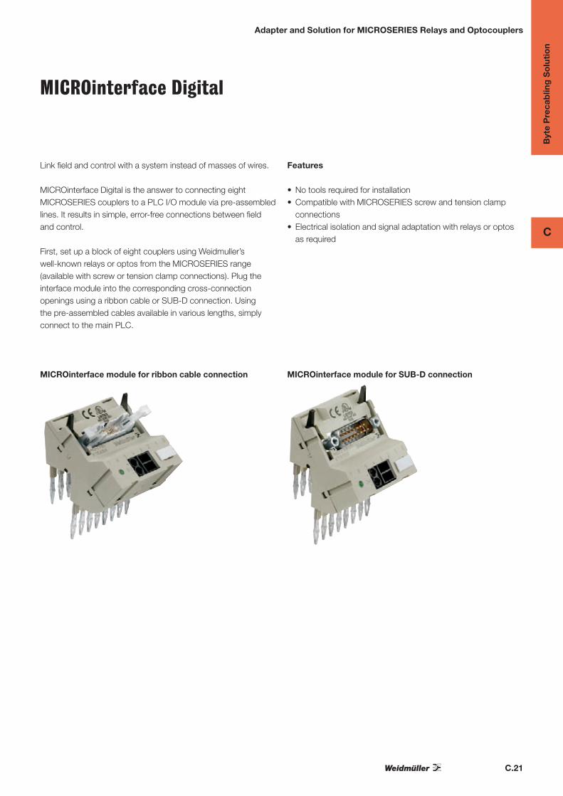
MICROinterface Digital
Link field and control with a system instead of masses of wires.
MICROinterface Digital is the answer to connecting eight MICROSERIES couplers to a PLC I/O module via pre-assembledlines. It results in simple, error-free connections between fieldand control.
First, set up a block of eight couplers using Weidmuller’s well-known relays or optos from the MICROSERIES range (available with screw or tension clamp connections). Plug the interface module into the corresponding cross-connection openings using a ribbon cable or SUB-D connection. Using the pre-assembled cables available in various lengths, simply connect to the main PLC.
Features
• No tools required for installation• Compatible with MICROSERIES screw and tension clamp
connections• Electrical isolation and signal adaptation with relays or optos
as required
MICROinterface module for ribbon cable connection MICROinterface module for SUB-D connection

C.22
Byt
e P
reca
blin
g S
olu
tio
n
C
Assemble a block of 8 MICROseries on the rail and adjust the stops
Insert the adapter in the transverse connection channel and ensure it is correctly positioned
Connect the prefabricated cable fitted with an HE10 or D-SUB connector
To remove the cable, move the two retainingclips apart
Push down on the center of the adapter from above
Instructions for assembling the adapter
Adapter and Solution for MICROSERIES Relays and Optocouplers

C.23
Byt
e P
reca
blin
g S
olu
tio
n
C
MICROinterface digital
Technical dataConnection data
Type ut module
Type of terminal / Connection system onnection;Available for
ribbon cable or Sub-D connection
Rated data
Operating voltage, max.
Current-carrying capacity
Total current feed, max.
Impulse withstand voltage (1.2/50 µs)
Rated insulation voltage
Storage temperature
Ambient temperature (operational)
Insulation coordination (EN 50 178)
Surge category
Pollution severity
Clearances/Creepage distances to EN
Clamping range (rating- / min. / max.) mm2
Length x width x height mm
Note
Ordering dataConnection system, pre-assembled cable
Ribbon cable connector, 10-pole
SUB-D plug, 15-pole
Ribbon cable connector, 10-pole
SUB-D plug, 15-pole
Note
AccessoriesNote
Adapter and Solution for MICROSERIES Relays and Optocouplers
MI8DI-S/Z
Input module
11
14
1.....................8
12
34
56
78
910
Connection data
Input module e
MICROSERIES;Screw or tension clamp connection;Available
for ribbon cable or Sub-D connection
Rated data
30 V AC/DC voltage, max.
0.5 A per channel capacity
2 A al current feed, max.
330 V se withstand voltage (1.2/50 µs)
32 V d insulation voltage
-20 °C…+85 °C ture
0 °C…+55 °C rature (operational)
Insulation coordination (EN 50 178)
I urge category
2 ollution severity
0.1 mm nces/Creepage distances to EN
2.5 / 0.5 / 2.5
48 x 59 x 53
Wiring diagram for ribbon cable
Type Qty Order No.
MI8DI-S F10 S 1 8773510000
MI8DI-S SUB D15S 1 8773460000
MI8DI-Z F10 S 1 8773530000
MI8DI-Z SUB D15S 1 8773490000
MI8DI-S = Screw connectionMI8DI-Z = Tension clamp connection
10-pole ribbon cable (see pg. C.33 for additional options) 823536000015-pole female D-Sub cable (see pg. C.31) 7789250xxx
MI8DO-S/Z
Output module
A2A2
A1A1
1.....................8
12
34
56
78
910
Connection data
Output module
MICROSERIES;Screw or tension clamp connection;Available
for ribbon cable or Sub-D connection
Rated data
30 V AC/DC voltage, max.
0.5 A per channel capacity
2 A al current feed, max.
330 V se withstand voltage (1.2/50 µs)
32 V d insulation voltage
-20 °C…+85 °C ture
0 °C…+55 °C rature (operational)
Insulation coordination (EN 50 178)
I urge category
2 ollution severity
0.1 mm nces/Creepage distances to EN
2.5 / 0.5 / 2.5
48 x 59 x 53
Wiring diagram for SUB-D
Type Qty Order No.
MI8DO-S F10 S 1 8773600000
MI8DO-S SUB D15S 1 8773550000
MI8DO-Z F10 S 1 8773620000
MI8DO-Z SUB D15S 1 8773570000
MI8DI-S = Screw connectionMI8DI-Z = Tension clamp connection
10-pole ribbon cable (see pg. C.33 for additional options) 823536000015-pole female D-Sub cable (see pg. C.31) 7789250xxx

C.24
Byt
e P
reca
blin
g S
olu
tio
n
C
Relays – MICROSERIES
1 change-over contactAC/DC/UC coil
Modulee can be used as an universal interface between thecontroller and the actuator to switch small and medium-sized loads.
• Relay module interchangeable, also for an opto module
• 6.1 mm wide
• Pluggable cross-connection at input and output minimizesthe wiring workload.
11
14
12
A2
A1
11
14
12
A2
A1
11
14
12
A2
A1
11
14
12
A2
A1
(5/12 V DC)
(24/60 V DC)
(24/48/120 V UC)
(230 V AC)
Output
max. switching voltage AC1/Continuous current 250 V/6 A
min. switching power 12 V / 100 mA
Response time / Drop-out time 6.2ms/3.9ms
Contact base material AgSnO
Mechanical endurance 20*106 switching cycles
max. switching frequency at rated load 0.1 Hz
Rated data
Status indicator/Free wheel diode green LED/Yes
Reverse pol. prot available
Ambient temperature (operational) -25 °C…+50 °C
Storage temperature -40 °C…+60 °C
Humidity 40°C/93% RH, no condensation
Approvals CE; cULus;
Insulation coordination (EN 50178)
Standards EN 50178
Rated voltage 300 V
Impulse withstand voltage 4 kV
Clearance and creepage distances for control/load side ≥ 5.5 mm
Surge category III
Pollution severity 2
Protective separation to VDE 0106 part 101 Yes
Dimensions Screw connection Tension clamp connection
Clamping range (rating- / min. / max.) mm2 2.5 / 0.5 / 4 1.5 / 0.5 / 2.5
Length x width x height mm 93 / 6.1 / 92 94 / 6.1 / 91
Note Cross-connectors and markers - refer to MICROSERIES accessories
400
300
200
100
00.1 1 5
AC Ohmic load
DC Ohmic load
Limit curve
Volta
ge[V
]
Current [A]
Current–Temperature rise curve
Out
put c
urre
nt [A
]
Ambient temperature [C]
Sw
itchi
ng c
ycle
sS
witc
hing
cyc
les
Current [A]
Current [A]
Sw
itchi
ng c
ycle
s
acc. to
Applications

C.25
Byt
e P
reca
blin
g S
olu
tio
n
C
Relays – MICROSERIES
1 change-over contactAC/DC/UC coil
Ordering dataInput
Rated voltage
Rated current AC
Rated current DC
Power rating
AC Response/dropout Volt
DC Response/dropout Volt
AC pickup/dropout current
DC pickup/dropout current
Ordering data Relay with socket
Screw connection Type
Order No.
Tension spring connection Type
Order No.
Ordering data Spare relay (pluggable)
Type
Order No.
Note
5 V DC 1CO
5 V DC ±20%
38.5 mA
193 mW
3.2V/1.6V
21.6mA/8mA
MRS 5Vdc 1CO
8556080000
MRZ 5Vdc 1CO
8556150000
RSS113005 05Vdc-Rel1U
4061580000
12 VDC 1CO
12 V DC ±20%
17 mA
210 mW
6.4V/ 2.5V
8.4mA/2.4mA
MRS 12Vdc 1CO
8556070000
MRZ 12Vdc 1CO
8556140000
RSS113012 12Vdc-Rel1U
4061610000
24 V DC 1CO
24 V DC ±20 %
6.6mA
160 mW
15.4V/6.5V
4mA/1.2mA
MRS 24Vdc 1CO
8533640000
MRZ 24VDC 1CO
8533660000
RSS113024 24Vdc-Rel1U
4060120000
24 V UC 1CO
24 V UC ±10 %
11 mA
6.4 mA
154 mW
15.8V/7V
15.8V/7V
3.6mA/1.3mA
3.6mA/1.3mA
MRS 24Vuc 1CO
8556050000
MRZ 24Vuc 1CO
8556120000
RSS113024 24Vdc-Rel1U
4060120000
Ordering dataInput
Rated voltage
Rated current AC
Rated current DC
Power rating
AC Response/dropout Volt
DC Response/dropout Volt
AC pickup/dropout current
DC pickup/dropout current
Ordering data Relay with socket
Screw connection Type
Order No.
Tension spring connection Type
Order No.
Ordering data Spare relay (pluggable)
Type
Order No.
Note
48 V UC 1CO
48 V UC ±10 %
5 mA
4 mA
190 mW
29V/11V
29V/11V
2.2mA/1.3mA
2.2mA/1.3mA
MRS 48Vuc 1CO
8556040000
MRZ 48Vuc 1CO
8556110000
RSS113048 48Vdc-Rel1U
4061620000
60 V DC 1CO
5 V DC ±20%
3.3 mA
200 mW
35V/11V
1.6mA/0.6mA
MRS 60Vdc 1CO
8556060000
MRZ 60Vdc 1CO
8556130000
RSS113060 60Vdc-Rel1U
4061630000
120 V UC 1CO
120 V UC + 10 %/ -15 %
3.5 mA
3.5 mA
0.42 VA
71V/22V
71V/22V
1.8mA/0.5mA
1.8mA/0.5mA
MRS 120Vuc 1CO
8556030000
MRZ 120Vuc 1CO
8556100000
RSS113060 60Vdc-Rel1U
4061630000
230 V AC 1CO
230 V AC ±10%
7.6 mA
1.75 VA
103V/49V
5mA/2.5mA
MRS 230Vac 1CO
8556020000
MRZ 230Vac 1CO
8556090000
RSS113024 24Vdc-Rel1U
4060120000

C.26
Byt
e P
reca
blin
g S
olu
tio
n
C
Relays – MICROSERIES
1 NO contactspecial versions
• 24 VDC actuator version:Bridgeable, potential-free connection for direct connection of actuators at the output
• 120 VAC RC version:RC circuit at the input guarantees safeswitching thresholds, e.g. for leakage currents on the con-trol side
• 230 V UC version:Can also be interconnected at input with DC signals
13
11
12
14
CC
14
A2
A1
A1
A2
(24 V DC)
(230 V UC)
(120 V AC RC)
11
14
12
A2
A1
Output
max. switching voltage AC1/Continuous current 250 V/6 A
min. switching power 12 V / 100 mA
Response time / Drop-out time 6.6 ms/5.8 ms
Contact base material AgSnO
Mechanical endurance 20*106 switching cycles
max. switching frequency at rated load 0.1 Hz
Rated data
Status indicator/Free wheel diode green LED/Yes
Reverse pol. prot available
Ambient temperature (operational) -25 °C…+ 55 °C
Storage temperature -40 °C…+60 °C
Humidity 40°C/93% RH, no condensation
Approvals CE; cULus;
Insulation coordination (EN 50178)
Standards EN 50178
Rated voltage 300 V
Impulse withstand voltage 4 kV (1.2/50 µs)
Clearance and creepage distances for control/load side ≥ 5.5 mm
Surge category III
Pollution severity 2
Protective separation to VDE 0106 part 101
Dimensions Screw connection Tension clamp connection
Clamping range (rating- / min. / max.) mm2 2.5 / 0.5 / 4 1.5 / 0.5 / 2.5
Length x width x height mm 93 / 6.1 / 92 94 / 6.1 / 91
Note Cross-connectors and markers - refer to MICROSERIES accessories
Ordering data
Ordering data Complete module
Screw connection Type
Order No.
Tension clamp connection Type
Order No.
Ordering data Spare relay, pluggable
Type
Order No.
Input
Rated voltage
Rated current AC
Rated current DC
Power rating
AC Response/dropout Volt
DC Response/dropout Volt
AC pickup/dropout current
DC pickup/dropout current
Note
24 V DC ACT
24 V DC ±20 %
6.6 mA
160 mW
15,4 V / 6,5 V
4 mA / 1,2 mA
MRS 24Vdc ACT
8660920000
MRZ 24VDC ACT
8660910000
RSS113024 24Vdc-Rel1U
4060120000
120 V AC 1CO RC
120 V AC + 10 %/ -15 %
7 mA
0.84 VA
79 V / 65 V
4.5 mA / 3.7 mA
MRS 120VUC 1CO RC
8825970000
MRZ 120VUC 1CO RC
8825960000
RSS113060 60Vdc-Rel1U
4061630000
230 V UC 1CO
230 V UC +10 % / -15 %
3.5 mA
2.9 mA
0.8 VA / 660 mW
146 V / 124 V
155 V / 115 V
1.9 mA / 1.5 mA
1.9 mA / 1.0 mA
MRS 230VUC 1CO
8825990000
MRZ 230VUC 1CO
8825980000
RSS113060 60Vdc-Rel1U
4061630000

C.27
Byt
e P
reca
blin
g S
olu
tio
n
C
Optos – MICROSERIES
MOS / MOZ 3…48 V DC / 0.1 A
Universal interface between control and sensor/actuator
• Plug-in cross-connection ZQV 4N
• Interchangeable solid-state relay
• 6.1 mm wide
• Screw or tension clamp connection
• For mounting on TS 35
(24 V DC)
(120 V UC)
(230 V AC)
Load side
Nominal switching voltage 3…48 V DC
Nominal switching current 0.1 A
Voltage drop at max. load ≤ 1 V
Leakage current ≤ 1 mA
Short-circuit-proof/Protective circuit no/Integrated free-wheel diode
General data
Ambient temperature (operational) -25 °C…+50 °C
Storage temperature -40 °C…+60 °C
Approvals CE; cULus;
Insulation coordination (EN 50 178)
Standards EN 50178
Rated voltage 300 V
Rated impulse withstand voltage 4.0 kV
Clearance and creepage distances for control/load side ≥ 5.5 mm
Surge category III
Pollution severity 2
Dimensions Screw connection Tension clamp connection
Clamping range (rating- / min. / max.) mm2 2.5 / 0.5 / 4 1.5 / 0.5 / 2.5
Length x width x height mm 93 / 6.1 / 92 94 / 6.1 / 91
Note Cross-connectors and markers - refer to MICROSERIES accessories
Ordering data
Ordering data Complete module
Screw connection Type
Order No.
Tension clamp connection Type
Order No.
Ordering data Spare relay, pluggable
Type
Order No.
Control side
Rated voltage
Power rating
max. input frequency
Switch-on delay
Switch-off delay
Note
5 V DC / 24 V DC 0.1 A
5 V DC ±20%
55 mW ±10 %
10 Hz
< 6,5 ms
< 10 ms
MOS 5Vdc / 24Vdc 0,1A
8633020000
MOZ 5Vdc / 24Vdc 0.1A
8633010000
SSS Relais 5V/24V 0,1ADC
4064320000
24 V DC / 24 V DC 0,1 A
24 V DC ±20 %
140 mW
300 Hz
35µs
355µs
MOS 24Vdc / 24Vdc 0.1A
8607340000
MOZ 24Vdc / 24Vdc 0,1A
8607360000
SSS Relais 24V/24V 0,1Adc
4061180000
120 V UC / 24 V DC 0,1 A
120 V UC + 10 %/ -15 %
340 mW / 0.4 VA
DC: 10 Hz /AC: 3 Hz
< 6.5 ms
< 10 ms
MOS 120Vuc / 24Vdc 0.1A
8607690000
MOZ 120Vuc / 24Vdc 0.1A
8607730000
SSS Relais 60V/24V 0,1Adc
4061230000
230 V AC / 24 V DC 0,1 A
230 V AC ±10%
1.7 VA
3 Hz
< 6.5 ms
< 10 ms
MOS 230Vac / 24Vdc 0.1A
8607710000
MOZ 230Vac / 24Vdc 0.1A
8607750000
SSS Relais 24V/24V 0,1Adc
4061180000

C.28
Byt
e P
reca
blin
g S
olu
tio
n
C
Optos – MICROSERIES
MOS / MOZ 24…240 V AC / 1 A
Universal interface between control and sensor/actuator
• Plug-in cross-connection ZQV 4N
• Interchangeable solid-state relay
• 6.1 mm wide
• Screw or tension clamp connection
• For mounting on TS 35
(24 V DC)
(120 V UC)
(230 V AC)
Load side
Nominal switching voltage 24…240 V AC
Nominal switching current 1 A
Voltage drop at max. load approx. 1.6 V
Leakage current ≤ 20 µA
Short-circuit-proof/Protective circuit no/Integrated free-wheel diode
General data
Ambient temperature (operational) -25 °C…+50 °C
Storage temperature -40 °C…+60 °C
Approvals CE; cULus;
Insulation coordination (EN 50 178)
Standards EN 50178
Rated voltage 300 V
Rated impulse withstand voltage 4.0 kV
Clearance and creepage distances for control/load side ≥ 5.5 mm
Surge category III
Pollution severity 2
Dimensions Screw connection Tension clamp connection
Clamping range (rating- / min. / max.) mm2 2.5 / 0.5 / 4 1.5 / 0.5 / 2.5
Length x width x height mm 93 / 6.1 / 92 94 / 6.1 / 91
Note Cross-connectors and markers - refer to MICROSERIES accessories
Ordering data
Ordering data Complete module
Screw connection Type
Order No.
Tension clamp connection Type
Order No.
Ordering data Spare relay, pluggable
Type
Order No.
Control side
Rated voltage
Power rating
max. input frequency
Switch-on delay
Switch-off delay
Note
24 V DC / 230 V AC 1 A
24 V DC ±20 %
250 mW ± 15 %
3 Hz
< 11 ms
< 11 ms
MOS 24Vdc/ 230VAC 1A
8652010000
MOZ 24Vdc/ 230VAC 1A
8652020000
SSS Relais 24V/230V 1Aac
4061210000
120 V UC / 230 V AC 1 A
120 V UC + 10 %/ -15 %
0.4 VA ±15%
3 Hz
< 11 ms
< 11 ms
MOS 120Vuc / 230VAC 1A
8651930000
MOZ 120Vuc / 230VAC 1A
8651950000
SSS Relais 60V/230V 1Aac
4061220000
230 V AC / 230 V AC 1 A
230 V UC ±10 %
1,7 VA ± 20%
3 Hz
< 20 ms
< 20 ms
MOS 230Vuc/ 230Vac 1A
8651990000
MOZ 230Vuc/ 230VAC 1A
8651970000
SSS Relais 24V/230V 1Aac
4061210000

C.29
Byt
e P
reca
blin
g S
olu
tio
n
C
Optos – MICROSERIES
MOS / MOZ 3…33 V DC / 2 A
Universal interface between control and sensor/actuator
• Plug-in cross-connection ZQV 4N
• Interchangeable solid-state relay
• 6.1 mm wide
• Screw or tension clamp connection
• For mounting on TS 35
(230 V AC)
(120 V UC)
(24 V DC)
Load side
Nominal switching voltage 3…33 V DC
Nominal switching current 2 A
Voltage drop at max. load ≤ 120 mV
Leakage current ≤ 1 mA
Short-circuit-proof/Protective circuit no/Integrated free-wheel diode
General data
Ambient temperature (operational) -25 °C…+50 °C
Storage temperature -40 °C…+60 °C
Approvals CE; cULus;
Insulation coordination (EN 50 178)
Standards EN 50178
Rated voltage 300 V
Rated impulse withstand voltage 4.0 kV
Clearance and creepage distances for control/load side ≥ 5.5 mm
Surge category III
Pollution severity 2
Dimensions Screw connection Tension clamp connection
Clamping range (rating- / min. / max.) mm2 2.5 / 0.5 / 4 1.5 / 0.5 / 2.5
Length x width x height mm 93 / 6.1 / 92 94 / 6.1 / 91
Note Cross-connectors and markers - refer to MICROSERIES accessories
Ordering data
Ordering data Complete module
Screw connection Type
Order No.
Tension clamp connection Type
Order No.
Ordering data Spare relay, pluggable
Type
Order No.
Control side
Rated voltage
Power rating
max. input frequency
Switch-on delay
Switch-off delay
Note
5 V DC / 24 V DC 2 A
5 V DC ±20%
55 mW ±10 %
300 Hz
< 55 µs
< 1 ms
MOS 5Vdc / 24Vdc 2A
8633000000
MOZ 5Vdc / 24Vdc 2A
8632990000
SSS Relais 5V/24V 2ADC
4064310000
24 V DC / 24 V DC 2 A
24 V DC ±20 %
140 mW
300 Hz
< 55 µs
< 1.2 ms
MOS 24Vdc / 24Vdc 2A
8607350000
MOZ 24Vdc / 24Vdc 2A
8607370000
SSS Relais 24V/24V 2Adc
4061190000
120 V UC / 24 V DC 2 A
120 V UC + 10 %/ -15 %
340 mW / 0.4 VA
DC: 10 Hz /AC: 3 Hz
< 6.5 ms
< 10 ms
MOS 120Vuc / 24Vdc 2A
8607700000
MOZ 120Vuc / 24Vdc 2A
8607740000
SSS Relais 60V/24V 2Adc
4061200000
230 V AC / 24 V DC 2 A
230 V AC ±10%
1.7 VA
3 Hz
< 6.5 ms
< 10 ms
MOS 230Vac / 24Vdc 2A
8607720000
MOZ 230Vac / 24Vdc 2A
8607760000
SSS Relais 24V/24V 2Adc
4061190000

C.30
Byt
e P
reca
blin
g S
olu
tio
n
C
Optos – MICROSERIES
MOS / MOZ actuator version 3…33 V DC / 2 A
Universal interface between control and sensor/actuator
• Plug-in cross-connection ZQV 4N
• Interchangeable solid-state relay
• 6.1 mm wide
• Screw or tension clamp connection
• For mounting on TS 35
• 24 V DC actuator version:Bridgeable, potential-free connection of actuators on out-put
(24 V DC)cc
13
Load side
Nominal switching voltage 3…33 V DC
Nominal switching current 2 A
Voltage drop at max. load ≤ 120 mV
Short-circuit-proof/Protective circuit no/Integrated free-wheel diode
General data
Ambient temperature (operational) -25 °C…+50 °C
Storage temperature -40 °C…+60 °C
Approvals CE; cULus;
Insulation coordination (EN 50 178)
Standards EN 50178
Rated voltage 300 V
Rated impulse withstand voltage 4.0 kV
Clearance and creepage distances for control/load side ≥ 5.5 mm
Surge category III
Pollution severity 2
Dimensions Screw connection Tension clamp connection
Clamping range (rating- / min. / max.) mm2 2.5 / 0.5 / 4 1.5 / 0.5 / 2.5
Length x width x height mm 93 / 6.1 / 92 94 / 6.1 / 91
Note Cross-connectors and markers - refer to MICROSERIES accessories
Ordering data
Ordering data Complete module
Screw connection Type
Order No.
Tension clamp connection Type
Order No.
Ordering data Spare relay, pluggable
Type
Order No.
Control side
Rated voltage
Power rating
max. input frequency
Switch-on delay
Switch-off delay
Note
24 V DC ACT
24 V DC ±20 %
140 mW ±10 %
< 55 µs
< 1,2 ms
MOS 24Vdc / 24Vdc ACT
8676250000
MOZ 24Vdc / 24Vdc ACT
8676230000
SSS Relais 24V/24V 2Adc
4061190000

C.31
Byt
e P
reca
blin
g S
olu
tio
n
C
Universal Cables
H-system cables
All PLCs
Card type
Order No.
Data
Interface connector
Cable type
Resistance
PLC connector
16-Input/Output card (LC)
7789388xxx
HE - 20-pole female
0.14 mm2 LIYY
< 150 Ω/km
No connector - ferrules
16-Input/Output card
7789100xxx
HE - 20-pole female
0.25 mm2 LIYY
< 80 Ω/km
No connector - ferrules
S-system cables
All PLCs
Card type
Order No.
Data
Interface connector
Cable type
Resistance
PLC connector
4-Input/Output card
7789250xxx
D-Sub - 15-pole female
0.25 mm2 LIYCY
< 80 Ω/km
No connector - ferrules
8-Input/Output card
7789252xxx
D-Sub - 25-pole female
0.25 mm2 LIYCY
< 80 Ω/km
No connector - ferrules
16-Input/Output card
7789254xxx
D-Sub - 37-pole female
0.25 mm2 LIYCY
< 80 Ω/km
No connector - ferrules
8 - 16-Input/Output card
7789262xxx
D-Sub - 37-pole female
0.25 mm2 LIYCY
< 80 Ω/km
D-Sub - 37-pole male
16-Input/Output card (LC)
7789301xxx
HE - 20-pole female
0.14 mm2 LIYY
< 150 Ω/km
HE – 20-pole female
16-Input/Output card
7789306xxx
HE - 20-pole female
0.25 mm2 LIYY
< 80 Ω/km
HE – 20-pole female
C.32
Byt
e P
reca
blin
g S
olu
tio
n
C
Universal Cables
No. Color
1 White
2 Brown
3 Green
4 Yellow
5 Gray
6 Pink
7 Blue
8 Red
9 Black
10 Violet
11 Gray/Pink
12 Red/Blue
13 White/Green
14 Brown/Green
15 White/Yellow
16 Yellow/Brown
17 White/Gray
18 Gray/Brown
19 White/Pink
20 Pink/Brown
21 White/Blue
No. Color
22 Brown/Blue
23 White/Red
24 Brown/Red
25 White/Black
26 Brown/Black
27 Gray/Green
28 Yellow/Gray
29 Pink/Green
30 Yellow/Pink
31 Green/Blue
32 Yellow/Blue
33 Green/Red
34 Yellow/Red
35 Green/Black
36 Yellow/Black
37 Gray/Blue
38 Pink/Blue
39 Gray/Red
40 Pink/Red
41 Gray/Black
42 Pink/Black
No. Color
43 Blue/Black
44 Red/Black
45 White/Brown/Black
46 Yellow/Green/Black
47 Gray/Pink/Black
48 Blue/Red/Black
49 White/Green/Black
50 Green/Brown/Black
51 White/Yellow/Black
52 Yellow/Brown/Black
53 White/Gray/Black
54 Gray/Brown/Black
55 White/Pink/Black
56 Pink/Brown/Black
57 White/Blue/Black
58 Brown/Blue/Black
59 White/Red/Black
60 Brown/Red/Black
61 Black/White
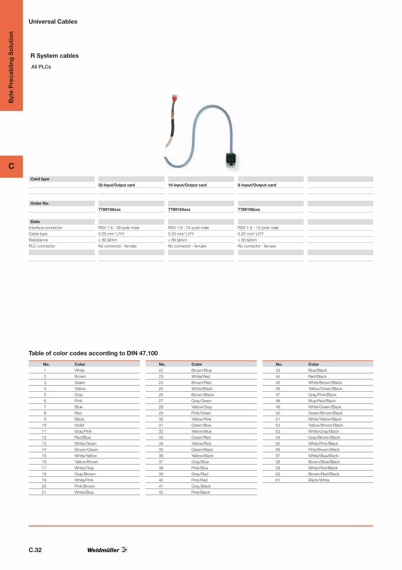
Table of color codes according to DIN 47.100
R System cables
All PLCs
32-Input/Output card
7789106xxx
RSV 1.6 - 36-pole male
0.25 mm2 LIYY
< 80 Ω/km
No connector - ferrules
16-Input/Output card
7789104xxx
RSV 1.6 - 24-pole male
0.25 mm2 LIYY
< 80 Ω/km
No connector - ferrules
8-Input/Output card
7789108xxx
RSV 1.6 - 12-pole male
0.25 mm2 LIYY
< 80 Ω/km
No connector - ferrules
Card type
Order No.
Data
Interface connector
Cable type
Resistance
PLC connector

C.33
Byt
e P
reca
blin
g S
olu
tio
n
C
Universal Cables
Ribbon round conductor designed on both sides
Type Length* Order No.
10-pole plug connector for transfer of 1 byte
to DIN 41651 / IEC 603-1
FBK 10/100 RK 1.00 m 8235360000
FBK 10/200 RK 2.00 m 8235380000
FBK 10/350 RK 3.50 m 8235410000
FBK 10/400 RK 4.00 m 8235420000
FBK 10/500 RK 5.00 m 8235440000
Ribbon round conductor designed on both sides
Type Length* Order No.
40-pole plug connector for transfer of 4 byte
to DIN 41651 / IEC 603-1
FBK 40/050 RK 1.00 m 8216350000
FBK 40/150 RK 1.50 m 8216360000
FBK 40/200 RK 2.00 m 8216370000
FBK 40/250 RK 2.50 m 8216380000
FBK 40/300 RK 3.00 m 8216390000
FBK 40/350 RK 3.50 m 8216400000
FBK 40/400 RK 4.00 m 8216410000
FBK 40/500 RK 5.00 m 8235350000
Rated voltage
Current carrying capacity
Total current load
- 40-pole lead
- 10-pole lead
Rated cross-section of cores
Resistance value
Storage temperature
300 V
1 A
26 A/∅T = 20 K
11,5 A/∅T = 20 K
0,14 mm2
55 mΩ/m
-10 ºC...+80 ºC
Preassembled control leadThe control lead is preassembled with 10 or 40 poleplug-in socket according to IEC 603/1 DIN 41 651.
It is used for connecting the PLC front adapter withthe passive or active PLC input/output modules.
The connecting line for the PLC system interface isavailable in standard lengths of 1m to 5m.
Technical data
Ordering data Ordering data
Spring socket DIN 416451 / IEC 603-1No. Color code Function
1 black B-
2 brown B3 +
3 red B3.7
4 orange B3.6
5 yellow B3.5
6 green B3.4
7 blue B3.3
8 violet B3.2
9 gray B3.1
10 white B3.0
11 white/black B-
12 white/brown B2 +
13 white/red B2.7
14 white/orange B2.6
15 white/yellow B2.5
16 white/green B2.4
17 white/blue B2.3
18 white/violet B2.2
19 white/gray B2.1
20 brown/black B2.0
21 brown/red B-
22 brown/orange B1 +
23 brown/yellow B1.7
24 brown/green B1.6
25 brown/blue B1.5
26 brown/violet B1.4
27 brown/gray B1.3
28 brown/white B1.2
29 green/black B1.1
30 green/brown B1.0
31 green/red B-
32 green/orange B0 +
33 green/blue B0.7
34 green/violet B0.6
35 green/gray B0.5
36 green/white B0.4
37 yellow-black B0.3
38 yellow-brown B0.2
39 yellow-red B0.1
40 yellow-orange B0.0
* special lengths on request

C.34
Byt
e P
reca
blin
g S
olu
tio
n
C
Electromechanical relays
Static relays
Relay type
Order No.
Data
Coil rated voltage
Coil rated current/Power consumption
Release Voltage/Min. holding current
Contact configuration
Contact material
Max. turn on delay / max turn-off delay
Power/ max. resistive load switchable under AC
Power/max. switchable resistive load under DC
Max. current
Min. switchable load
Dielectric strength voltage (coil/contact)
Dielectric strength voltage (between contacts of the same pole)
Dielectric strength voltage (between contacts of different poles)
Mechanical service life
Electrical service life
Type Riderseries - 1CO
RCL 314024 8693260000
24 Vdc (+10, -30%)
17 mA / 0.4 VA
2.4 V/1.6 mA
1CO
AgNi 90/10
7 ms / 3 ms (20 ms with damping diode.)
4000 VA / 250 V - 16 A (cosϕ=1)
300 W / 30 V - 10 A (L/R=0 ms)
16 A
10 mA/ 12 V
4000 Vac (50/60Hz) / 1 min.
1000 Vac (50/60Hz) / 1 min.
-
30 x 106 switching cycles
1 x 10⁵ switching cycles (2500 VA - cosϕ=1)
Type Microseries - 1CO
RSS 113024 (standard) 4060120000
RSS 112024 (Au plated) 4061590000
Standard Au plated
24 Vdc (+/– 20%)
6.6 mA / 160 mW
6.5 V/ 1.2 mA
1CO
AgSnO2 AgSnO2 5µ Au
5 ms / 2.5 ms
1500 VA / 250 V - 6 A (cosϕ=1)
–
6 A
100 mA / 12 V 10 mA / 12 V
20 x 106 switching cycles
6 x 10⁴ switching cycles (1500 VA - cosϕ=1)
Type Riderseries - 2CO
RCL 424024 4058570000
24 Vdc (+10, -30%)
17 mA / 0.4 VA
2.4 V/ 1.6 mA
2CO
AgNi 90/10
7 ms / 3 ms (20 ms with damping diode.)
2000 VA / 250 V - 8 A (cosϕ=1)
150 W / 30 V - 5 A (L/R=0 ms)
8 A
10 mA/ 12 V
4000 Vac (50/60Hz) / 1 min.
1000 Vac (50/60Hz) / 1 min.
2500 Vac (50/60Hz) / 1 min.
30 x 106 switching cycles
1 x 10⁵ switching cycles (1250 VA - cosϕ=1)
Type Plugseries - ODC
STD 07205 8576340000
15...24 Vdc / 12...30 Vdc
max. 10 mA
–
max. 30 Vdc
0.001...2.5 Adc
12 Adc (1 s)
2 ms max.
18 ms max.
max. 0.4 V
10 µA
4000 Vac
Type Microseries
SSS 24/24-100mA 4061180000
SSS 24/24-2A 4061190000
100 mA version 2 A version
24 Vdc/16...30 Vdc 24 Vdc/16...30 Vdc
7 mA ±10% 7 mA ±10%
10 Vdc 10 Vdc
3…48 Vdc 3…33 Vdc
100 mAdc max. 2 Adc
– –
– –
– –
<1 V <120 mV
– –
2500 Vac 2500 Vac
Type Plugseries - OAC
STA 07220 8576370000
15...24 Vdc - / 12...30 Vdc
max. 10 mA
–
12...275 Vac
0.05...2 Aac
100 Aac (10 ms)
12 ms max.
20 ms max.
-
10 µA
4000 Vac
Static relay type
Order No.
Data
Rated input voltage/operating voltage
Input current
Drop out voltage
Output voltage
Output current
Inrush current
Turn-on delay
Turn-off delay
Output voltage drop
Leakage current
Dielectric strength voltage (input/output)
Accessories

C.35
Byt
e P
reca
blin
g S
olu
tio
n
C
Accessories
Type Qty Order No.Base only
MRZ 24VDC 1CO BASIS 10 8826000000
MRS 24VDC 1CO BASIS 10 8826010000
MRZ 120VUC 1CO BASIS 10 8826020000
MRS 120VUC 1CO BASIS 10 8826030000
MRZ 230VAC 1CO BASIS 10 8826040000
MRS 230VAC 1CO BASIS 10 8826050000
Markers
WS 12/6 12 x 6 mm 200 1061160000
Labels, Lasermark
LM MT 300 15/6 ge 484 labels / sheet 10 1686360000
Screwdriver
SD 0,6 x 3,5 x 100 10 9008330000
Accessories General data – MICROSERIES
Tension clamp ScrewConductor connection connection
Solid H07V-U mm2 0.5 … 2.5 0.5 … 4.0
Stranded H07V-K mm2 0.5 … 2.5 0.5 … 2.5
“f” with wire end ferrules to DIN 46228-1 mm2 0.5 … 1.5 0.5 … 1.5
“f” with wire end ferrules with plastic collar mm2 0.5 … 1.5 0.5 … 1.5
Max. clamping range mm2 0.13 … 2.5 0.13 … 4.0
Plug gauge to IEC 60947-1 size A 2 A 3
General technical data
Nominal torque - 0.6
Continuous current for 2-pole cross-connection A 10 10
Continuous current for multi-pole cross-connection A 10 10
Stripping length mm 10 7
Ingress protection class IP 20 IP 20
Housing material Wemid Wemid
UL 94 flammability rating V-0 V-0
Nominal current A 6 6
Nominal voltage V 250 250
Plug-in cross-connection Technical dataType No. of poles Qty Order No.yellow
ZQV 4N / 2 GE 2 60 1758250000
ZQV 4N / 3 GE 3 60 1762630000
ZQV 4N / 4 GE 4 60 1762620000
ZQV 4N / 10 GE 10 20 1758260000
ZQV 4N / 20 20 20 1909020000
red
ZQV 4N / 2 RT 2 60 1793950000
ZQV 4N / 3 RT 3 60 1793980000
ZQV 4N / 4 RT 4 60 1794010000
ZQV 4N / 10 RT 10 20 1794040000
ZQV 4N / 20 RT 20 20 1909150000
blue
ZQV 4N / 2 BL 2 60 1793960000
ZQV 4N / 3 BL 3 60 1793990000
ZQV 4N / 4 BL 4 60 1794020000
ZQV 4N / 10 BL 10 20 1794050000
ZQV 4N / 20 BL 20 20 1909100000
black
ZQV 4N / 2 SW 2 60 1793970000
ZQV 4N / 3 SW 3 60 1794000000
ZQV 4N / 4 SW 4 60 1794030000
ZQV 4N / 10 SW 10 20 1794060000
ZQV 4N / 20 SW 20 20 1909120000
Other accessories Dimensions
Tension clamp connection Screw connection
91 m
m
94 mm
6.1
mm
92 m
m
93 mm
6.1
mm

C.36
Byt
e P
reca
blin
g S
olu
tio
n
C