contact lens monthly update on corneal … · for topography in general clinical practice and refer...
TRANSCRIPT

TODAY, EYE CARE CLINICIANSknow what a corneal topographer is andwhat it can be used for.
Nevertheless, it is not always clear thatall will know how to interpret the resultsgiven by the instruments and how tooptimise the use of their applications. Thismay partly explain why, despite the factthat these devices have been around formany years and have dropped consider-ably in price, they have not becomecommonplace in primary eye carepractices yet.
Different methods have been appliedby different clinical topographers todetermine anterior corneal topography; agood description of each method can befound in the literature.1 Certainly, themost popular is Placido-based cornealtopography, as used by most cornealtopographers, such as Nidek’s latest devicethe Magellan Mapper.
This device uses a Placido cone,enabling the instrument to be placedcloser to the patient’s eye, thus givinglarger corneal coverage than some discsystems, although disc-based systems (forexample, the Oculus Keratograph) mayhave fewer focusing errors.
Over the last decade, and certainlymotivated by the advent of refractivesurgery, topography systems haveimproved considerably. Many of the initialalgorithm inaccuracies have been dealtwith.
The Orbscan IIz system, from Bausch& Lomb, is a popular and extremelyuseful clinical tool that allows the determi-nation of a number of ocular parameters ofthe anterior segment, namely anterior andposterior corneal surface topographies (ina number of different displays), cornealthickness and anterior chamber depth.
Additionally, knowing these parame-ters allows the system to offer a series ofapplications such asiridocorneal angleestimation, determi-nation of a correctionfactor to apply topneumo-tonometryreadings based oncorneal shape charac-teristics and also
16
C O N T A C T L E N S M O N T H L Y
Dr Shehzad Naroo and Alejandro Cervino describe the potentialfor topography in general clinical practice and refer to a case wherethe data obtained was essential for accurate contact lens fitting
Update on corneal topographersand their use in CL practice
simulation of contact lens fitting andfluorescein patterns.
The system uses a slit scanningtechnique. Forty sections of the corneaare recorded in two scans, each of whichtakes approximately 0.7 seconds, that is aslit scan is performed from left to rightand then from right to left obtaining 20frames of corneal sections at differentlocation during each of those scans.
The data obtained from the section isused to reconstruct the surfaces. Slitscanning techniques would avoid theapproximation errors that arise fromPlacido-based systems since each surfaceis measured directly.
Nevertheless, the technique hasdisadvantages as well. First, the fact ofbeing a scanning technique means that ifthe measure is not instantaneous, and if ittakes more than 30 milliseconds, the
ocular micromovements must be takeninto account. The Orbscan IIz solves thisproblem by using a tracking system.Figure 1a shows the original Orbscan unit;note that it does not have a Placido disc,which was introduced on the later version(Figure 1b).
Another recent device, the OculusPentacam from Oculus, in Giessen,Germany, has also moved away from theidea of Placido technology and uses arotating Scheimpflug camera.
This allows structures behind thecornea to be imaged too. It provides datafrom the anterior and posterior cornealshape (represented as either elevation orcurvature data), plus corneal pachymetrydata, anterior chamber volume, anteriorchamber depth and anterior chamberangle. There is also a useful image of theanterior lens surface and, in patients witha sufficiently large pupil, the posterior lenssurface can also be imaged (althoughshape of power data in not given for thelens). Figure 2 shows an image from the
FIGURE 2. Image from the
Pentcam
FIGURE 1a. OriginalOrbscan unit.Courtesy of Bauschand Lomb
FIGURE 1b. The later Orbscan
unit with Placido disc
www.optometryonline.netOptician AUGUST 6, 2004 NO 5963 VOL 228
17
C O N T A C T L E N S M O N T H L Y
AUGUST 6, 2004 NO 5963 VOL 228 Opticianwww.optometryonline.net
▲
Pentcam. All this information collectedby topography systems comes fromthousands of points, and needs to beconverted into some form that allows aquick interpretation of the information.To take full advantage of the cornealtopography measures, one must be able todifferentiate rapidly and effectively thedifferent conditions that may appear.
There are a number of ways torepresent topography data: numeric, withpowers displayed over the surface pointwhere it was collected; wire-meshrepresentation, allowing 3D modelling;and colour-coded contour maps, allowingan easier interpretation.
The maps are considered the standardfor representation of topography. A cornealtopography map is a 2D displayrepresenting the variations in curvatureas we move from the centre towards theperiphery. In these maps, differences incurvature are represented by a colourlegend in which each colour covers avariable range of dioptres. These changesin colour will form the pattern, which tellsthe practitioner the topographic variationsof the corneal surface.
The clinical utility of these mapsdepends on the interpretation skills of thepractitioner, as well as the colour-codedmaps’ capability to be interpreted.2 Thisinvolves two aspects:
The colour association, with the coldcolours (blues) representing the low
powers, large radius, flattest surfaces ordepressions from a reference point (thelatter would apply if considering anelevation map), and the warm colours(reds) representing the high powers, shortradius, steepest surfaces or elevations froma reference point (the latter would applyif considering an elevation map).
Pattern recognition to allow differenti-ation of different topographic entities fromthe regular corneal contours, this involvesusing a series of different scales in thetopography systems.
All the topography systems offer thepossibility of changing and customisingthe colour-scale in order to reveal aspectsof interest of the corneal topography, or tohide the normal variation and make theidentification of different abnormalentities easier.
The relative scale (or normalised scale)is set for that individual cornea, the middlecolour on the scale (usually green) isallocated to the middle radius of curvatureof that cornea and all other radii are plottedat small intervals (usually 0.25-0.50dioptres) – this scale would allow subtleirregularities to be shown better. Theabsolute (or standardised scale) is pre-setby the machine and uses the same scale forall pictures taken on that device, namely,the steepest and flattest curvatures arepre-set and the intervals between thecolours are usually 1 dioptre – this scalewould allow different corneas to becompared (such as right eye versus lefteye), or an eye to be checked over time onthe same scale.
Nearly all corneal topography devicesincorporate contact lens fitting software.
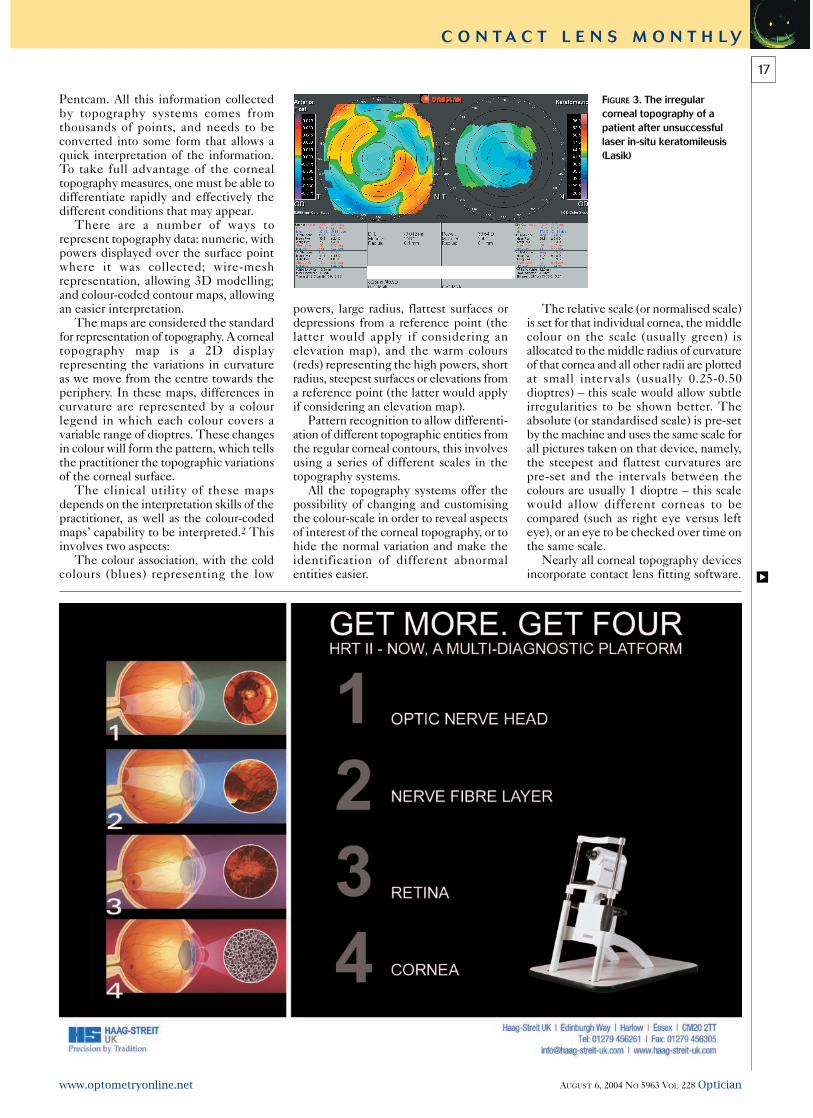
FIGURE 3. The irregularcorneal topography of apatient after unsuccessfullaser in-situ keratomileusis(Lasik)
18
C O N T A C T L E N S M O N T H L Y
Optician AUGUST 6, 2004 NO 5963 VOL 228 www.optometryonline.net
This software will range from pre-loadeddesigns of current lens manufacturers’stock lenses to those topography units thatallow the clinician to create their owncontact lens design.
The new Nidek Magellan Mapper, forexample, allows a corneal lens to becreated with up to seven customisedperipheral curves. The Orbscan IIz allowscreation of a clinician’s own contact lensdesigns or selection of pre-loadedmanufacturers’ designs.
Figure 3 shows the irregular cornealtopography of a patient after unsuccessfullaser in-situ keratomileusis (Lasik).
The patient, a 32-year-old male formersoft lens wearer, had successful Lasik onhis left eye but had epithelial in-growthunder his corneal flap on his right eye. Hethen underwent flap ‘lift and clean’ butunfortunately had a flap melt resulting ina very irregular corneal profile to this eye.
His best corrected visual acuity withtrial lenses in the affected eye was 6/12+(refractive error was +1.00/-2.00x015).
It was decided to fit a rigid gas-permeable contact lens to this eye.Regular fitting sets were tried and with anover refraction the best corrected visualacuity improved to 6/5 but lens stabilitywas very poor.
It was decided to fit a contact lensspecifically to his corneal shape using theOrbscan IIz contact lens fitting software,Fitscan. The default lens that theprogramme created (Figure 4) was orderedto a mean spherical equivalent power of -1.00 dioptres. This lens was found to beunderpowered and too mobile, so the lensfit was steepened and peripheral curvesaltered slightly to improve tear flowaround the new tighter lens, and the powerwas re-ordered incorporating the positivetear lens (Figure 5).
The new power ordered was -3.00dioptres. This lens was found to becomfortable by the patient and providedexcellent Snellen acuity (6/5). The patientused this lens successfully for manymonths but nearly a year after he initiallypresented he returned complaining ofincreased lens awareness and worseningvision. His corneal profile was found tohave altered further. This time a contactlens was refitted using the Keratron Scoutcorneal topographer. This device links
directly to the Wave contact lenses that arespecifically custom-made to the cornealshape by Northern Lenses.
These lenses have variable refractivepower plus a variable base curve. Figures6a and 6b show the fluorescein pattern ofthis lens design.
In the top section of each figure notethe very small post-lens tear film, theresult of this can be seen in the simulatedfluorescein pattern which shows very littlefluorescein pooling. Also, note the whiteradius marker on the fluoresecin pattern(bottom right in each picture) in the twofigures is located at different places in thetwo pictures, the corresponding power andbase curve reading (bottom left in eachpicture) is different in each picture – thushighlighting the unusual design of theWave contact lenses.
In Figure 6a the power is -0.81 dioptresand base curve is 8.29 mm and in Figure6b the power is +0.38 dioptres and thebase curve is 8.54 mm. So far the patienthas been happy with this lens.
Many practices will own cornealtopography devices but may not haveutilised them for more than screening ofcorneal abnormalities, although the uses ofthese devices stretch much further thanthat. Some devices have additionalcapabilities (such as poster shape andpachymetry measures with Orbscan IIzand Pentacam) or ocular wavefront maps(such as Nidek OPD unit) or cornealwavefront maps (Keratron Scout, OculusKeratograph and others) and of course thecontact lens fitting software. Figure 7shows a 3D fluorescein simulation fromthe Magellan Mapper.
REFERENCES1 Dave T. Current developments in measurementsof corneal topography; Contact Lens and Anterior Eye,1998;21(Supplement):S13-S30.2 Naroo SA, Cervino A. Corneal topography and itsrole in refractive surgery; In Naroo SA, (editor),Refractive Surgery: A guide to assessment and management.London: Butterworth-Heinemann; 2004, pp 9-16.
◆ Shehzad Naroo is a lecturer andAlejandro Cervino a research optometrist atAston University, School of Life and HealthSciences
FIGURES 6a and 6b. Fluorescein pattern of Wave lenses with variable refractive power plus avariable base curve
FIGURE 7. 3D fluorescein simulation byMagellan Mapper
FIGURE 4. The default lens that the programmecreated was ordered to a mean sphericalequivalent power of -1.00 dioptres
FIGURE 5. The new power
ordered was -3.00 dioptres