consumer electronics
DESCRIPTION
Electronic Servicing and ApplicationsTRANSCRIPT
Republic of the PhilippinesDEPARTMENT OF EDUCATION
K to 12 Basic Education CurriculumTechnology and Livelihood Education
Learning Module
CONSUMERELECTRONICS SERVICING
EXPLORATORY COURSEGrade 7 and Grade 8

TABLE OF CONTENTS
What Is This Module About ?.........................................................................2
How Do You Use This Module ………………………………………………3
LESSON 1 – Use Hand Tools................................................................4-22
LESSON 2 – Perform Mensuration and Calculation. . .23-53
LESSON 3 – Prepare and Interpret Technical Drawings...................................................................................................................................54-100
LESSON 4 – Practice Occupational Safety and Health.................................................................................................................................101-125
LESSON 5 – Maintain Tools and Equipment.................126-143
Answer Keys..................................................................................................144-151
Acknowledgment................................................................................................152
CONSUMER ELECTRONICS SERVICING 1K to 12 – Technology and Livelihood Education
What Is This Module About?Welcome to the world of Consumer Electronics Servicing!
This Module is an exploratory course which leads you to Consumer Electronics Servicing National Certificate Level II ( NC II)1. It covers five common competencies that a Grade 7 / Grade 8 Technology and Livelihood Education (TLE) student like you ought to possess, namely:
1) Use Hand Tools; 2) Perform Mensuration and Calculation; 3) Prepare and Interpret Technical Drawings; 4) Practice Occupational Safety and Health; and 5) Maintain Tools and Equipment
These five common competencies are covered separately in five lessons. As shown below, each lesson is directed to the attainment of one or three learning outcomes:
Lesson 1 – Use Hand ToolsLO1. Prepare hand toolsLO 2. Use appropriate hand tools and test equipment
Lesson 2 – Perform Mensuration and CalculationsLO 1. Select measuring instrumentsLO 2. Carry out measurements and calculationsLO 3. Maintain measuring instruments
Lesson 3 – Prepare and Interpret Technical DrawingsLO1. Identify different kinds of technical drawings LO2. Interpret technical drawingLO3. Prepare/Make changes in electrical/electronic schematics and diagrams
Lesson 4 – Practice Occupational Health and SafetyLO 1. Identify health hazards and occupational risksLO 2.Observe occupational and safety practices
Lesson 5 – Maintain Tools and EquipmentLO 1. Maintain hand tools and equipmentLO 2 Perform basic preventive maintenance of electronic tools and equipment
Your success in this exploratory course on Consumer Electronics Servicing can be seen in your ability to do the performance standards found in each lesson.
1NATIONAL CERTIFICATE (NC) is a certification issued to individuals who achieved all the required units of competency for a national qualification as defined under the Training Regulations. NCs are aligned to specific levels within the PTQF. (TESDA Board ResolutionNo. 2004-13, Training Regulations Framework)
NATIONAL CERTIFICATE LEVEL refers to the four (4) qualification levels defined in the Philippine TVET Qualifications Framework (PTQF) where the worker with:
a.NC I performs a routine and predictable tasks; has little judgment; and, works under supervision; b.NC II performs prescribed range of functions involving known routines and procedures; has limited choice and complexity of functions, and has little accountability;
CONSUMER ELECTRONICS SERVICING 2K to 12 – Technology and Livelihood Education
How Do You Use This Module?This Module has five Lessons. Each Lesson has the following parts:
Learning Outcomes Performance Standards Materials/Resources Definition of Terms What Do You Already Know? What Do You Need to Know? How Much Have You Learned? How Do You Apply What You Have Learned? How Well Did You Perform? References
To get the most from this Module, you need to do the following:
1. Begin by reading and understanding the Learning Outcome/s and Performance Standards. These will tell you what you should know and be able to do at the end of this Module.
2. Find out what you already know by taking the Pretest then check your answer against the Answer Key. If you get 99 to 100% of the items correctly, you may proceed to the next Lesson. This means that you need not go through theLesson because you already know what it is about. If you fail to get 99 to 100%correctly, go through the Lesson again and review especially those items whichyou failed to get.
3. Do the required Learning Activities. They begin with one or more InformationSheets. An Information Sheet contains important notes or basic information thatyou need to know.
After reading the Information Sheet, test yourself on how much you havelearned by means of the Self-check. Refer to the Answer Key for correction. Donot hesitate to go back to the Information Sheet when you do not get all testitems correctly. This will ensure your mastery of basic information.
4. Demonstrate what you learned by doing what the Activity / Operation /Job Sheetdirects you to do.
5. You must be able to apply what you have learned in another activity or in a real life situation.
6. Accomplish the Scoring Rubrics for you to know how well you performed.
Each Lesson also provides you with references and definition of key terms for your guide. They can be of great help. Use them fully.
If you have questions, ask your teacher for assistance.
CONSUMER ELECTRONICS SERVICING 3K to 12 – Technology and Livelihood Education

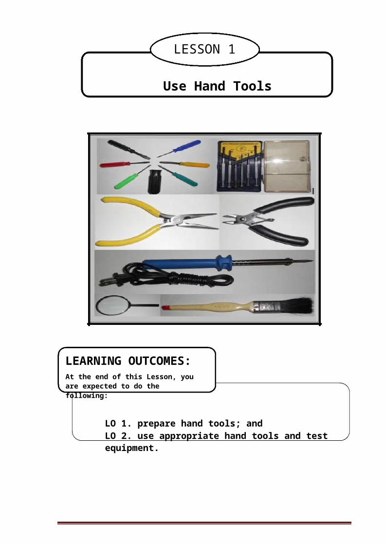
LESSON 1
Use Hand Tools
LEARNING OUTCOMES:At the end of this Lesson, you are expected to do the following:
LO 1. prepare hand tools; andLO 2. use appropriate hand tools and test equipment.
CONSUMER ELECTRONICS SERVICING 4
K to 12 – Technology and Livelihood Education
Definition of TermsAccidental - occurring unexpectedly, unintentionally, or by chance.Alternating current - an electric current that is continually varying in value and
reversing its direction of flow at regular intervalAnode - a positive electrode of semiconductor deviceCapacitance - a property that exists whenever two conductors are separated by
insulating material, permitting the storage of electricityCapacitor - a component designed intentionally to have a definite amount of
capacitanceCircuit - an arrangement of one or more complete paths of electron flow.Conductor - a wire, cable, or other body or medium that is suitable for carrying
electric currentCurrent - the rate of transfer of electricity from one point to anotherDesoldering - a process of unsoldering unwanted parts or components in the circuit
with the support of a soldering toolDielectric material - a material that serves as insulator because it has poor electric
conductivityDirect current - an electric current that flows in one direction Discrete components- separated or individual componentsElectronics - a branch of science and technology that deals with the controlled flow
of electronsFlammable - tending to burn quickly Hazards - risks; dangersMalfunction - not in normal operating conditionOhmmeter - an instrument that measures the amount of resistance in certain
component or circuitsResistance - the opposition that a component or material offers to the flow current Resistor – a component designed intentionally to have a definite amount of
resistanceSoldering - a process of joining two metals caused by heatSoldering technique - a strategy in which the solder (lead) is being applied in a
connection or in the printed circuit boardSplicing – connecting two lengths of conductorTechnician - a person skilled in mechanical or industrial techniques or in a particular
technical fieldTool kit - a small bag or box equipped with hand tools Troubleshooting - identifying and repairing faults in equipmentVoltage - the electrical pressure that exist between two points and capable of
producing a flow of current when a close circuit is connected between the points.
Voltmeter - an instrument that measures the amount of electromotive force in a component or circuit.
Acronyms
PCB – Printed Circuit BoardPPE – Personal Protective EquipmentVOM – Volt-Ohm-Milliameter
CONSUMER ELECTRONICS SERVICING 5K to 12 – Technology and Livelihood Education
LEARNING OUTCOME 1
Prepare Hand Tools
PERFORMANCE STANDARDS
Appropriate hand tools are identified. Appropriate tools are selected according to task requirements.
What Do You Already Know?Let us determine how much you already know about the different hand tools. Take this test.
Pretest LO 1
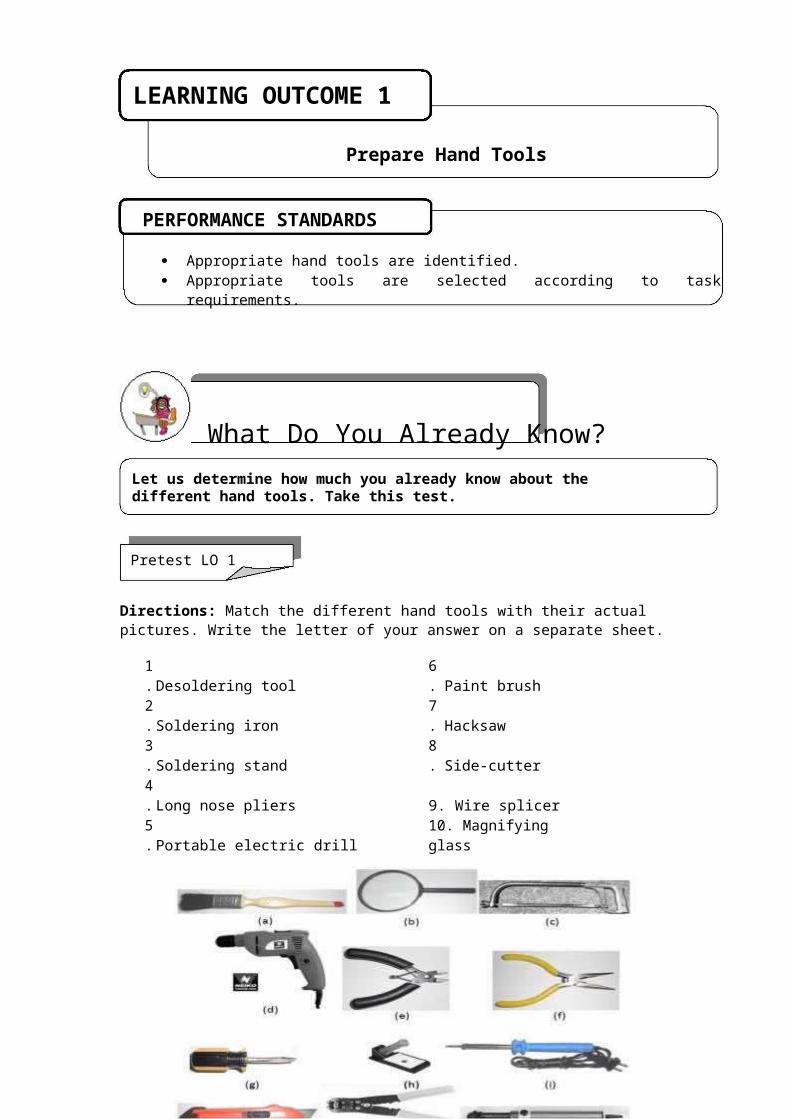
Directions: Match the different hand tools with their actual pictures. Write the letter of your answer on a separate sheet.
1. Desoldering tool 6. Paint brush2. Soldering iron 7. Hacksaw3. Soldering stand 8. Side-cutter4. Long nose pliers 9. Wire splicer5. Portable electric drill 10. Magnifying glass
CONSUMER ELECTRONICS SERVICING 6K to 12 – Technology and Livelihood Education

What Do You Need To Know?Read Information Sheet 1.1 very well; then, find out how much you can remember and how much you have learned by answering the Self-check.
Information Sheet 1.1
Basic Hand Tools
Driving of Tools
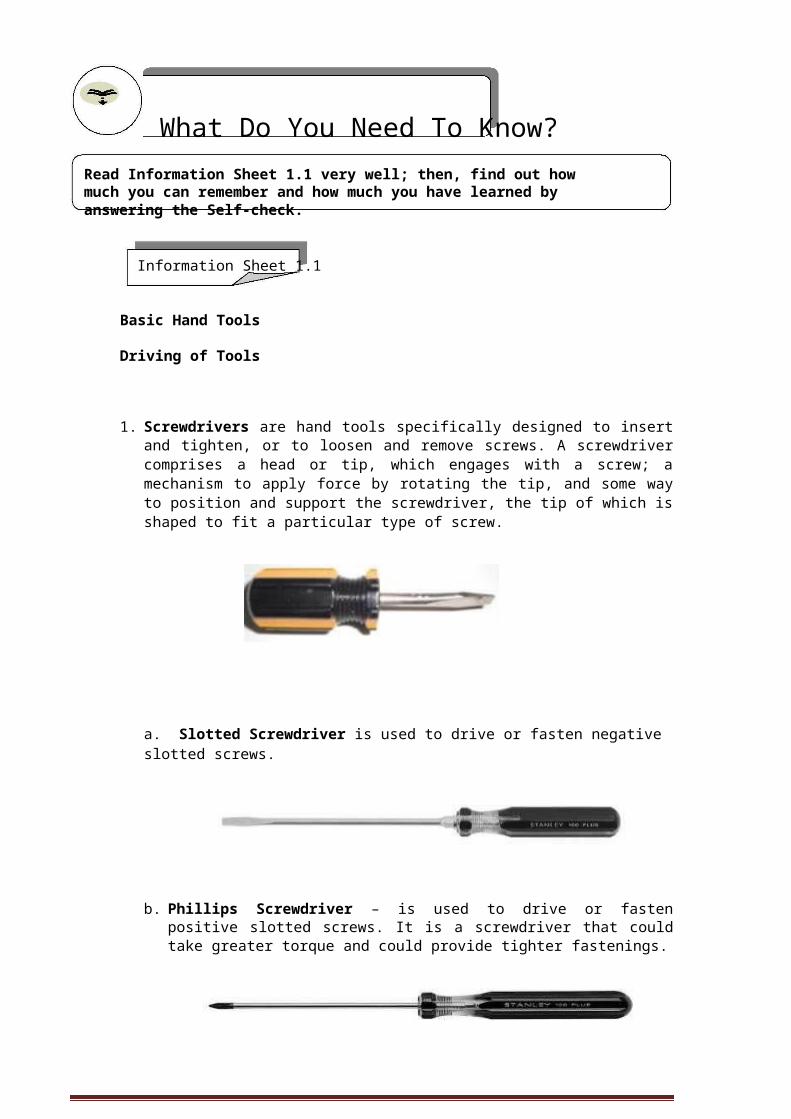
1. Screwdrivers are hand tools specifically designed to insert and tighten, or to loosen and remove screws. A screwdriver comprises a head or tip, which engages with a screw; a mechanism to apply force by rotating the tip, and some way to position and support the screwdriver, the tip of which is shaped to fit a particular type of screw.
a. Slotted Screwdriver is used to drive or fasten negative slotted screws.
b. Phillips Screwdriver – is used to drive or fasten positive slotted screws. It is a screwdriver that could take greater torque and could provide tighter fastenings.
CONSUMER ELECTRONICS SERVICING 7K to 12 – Technology and Livelihood Education
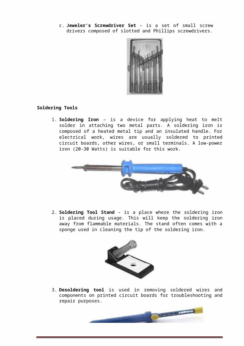
c. Jeweler's Screwdriver Set – is a set of small screw drivers composed of slotted and Phillips screwdrivers.
Soldering Tools
1. Soldering Iron – is a device for applying heat to melt solder in attaching two metal parts. A soldering iron is composed of a heated metal tip and an insulated handle. For electrical work, wires are usually soldered to printed circuit boards, other wires, or small terminals. A low-power iron (20-30 Watts) is suitable for this work.
2. Soldering Tool Stand – is a place where the soldering iron is placed during usage. This will keep the soldering iron away from flammable materials. The stand often comes with a sponge used in cleaning the tip of the soldering iron.
3. Desoldering tool is used in removing soldered wires and components on printed circuit boards for troubleshooting and repair purposes.
CONSUMER ELECTRONICS SERVICING 8K to 12 – Technology and Livelihood Education
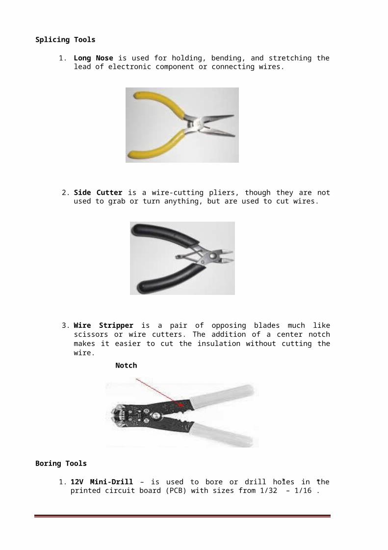
Splicing Tools
1. Long Nose is used for holding, bending, and stretching the lead of electronic component or connecting wires.
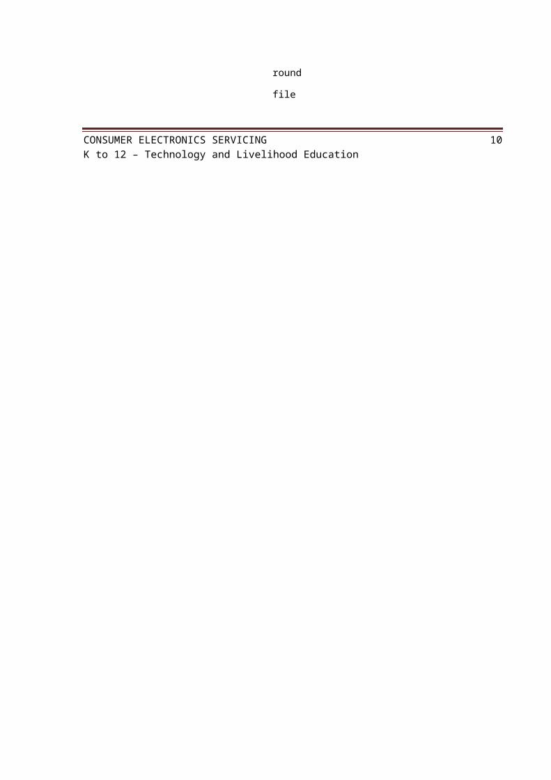
2. Side Cutter is a wire-cutting pliers, though they are not used to grab or turn anything, but are used to cut wires.
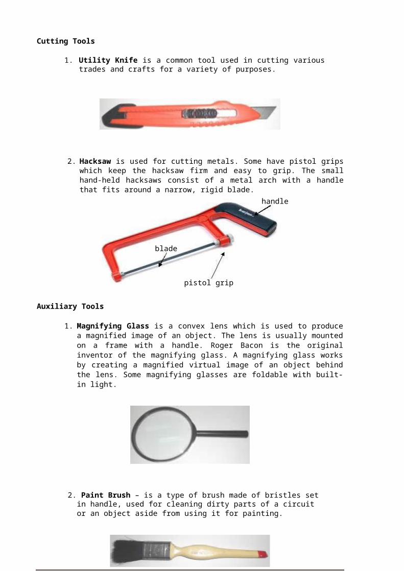
3. Wire Stripper is a pair of opposing blades much like scissors or wire cutters. The addition of a center notch makes it easier to cut the insulation without cutting the wire.
Notch
Boring Tools
1. 12V Mini-Drill – is used to bore or drill holes in the printed circuit board (PCB) with sizes from 1/32” – 1/16”.
CONSUMER ELECTRONICS SERVICING 9K to 12 – Technology and Livelihood Education
2. Portable Electric Drill is used for boring hole(s) in plastic or metal chassis with the use of drill bits having sizes from 1/6” to approximately 1/4”.
3. Metal Files These are hand tools having a series of sharp, parallel ridges or teeth. Most files have a narrow, pointed tang at one end to which a handle can be fitted.
Flat File is parallel in width and tapered in thickness; they are used for flat surfaces and edges.
Half Round File is tapered in width and thickness, coming to a point, and is narrower than a standard half round and used for filing inside of rings.
Round File - is also called rat-tail file which is gradually tapered and used for many tasks that require a round tool, such as enlarging round holes or cutting a scalloped edge.
triangular file
flat file
half-round file
round file
CONSUMER ELECTRONICS SERVICING 10K to 12 – Technology and Livelihood Education

Cutting Tools
1. Utility Knife is a common tool used in cutting various trades and crafts for a variety of purposes.
2. Hacksaw is used for cutting metals. Some have pistol grips which keep the hacksaw firm and easy to grip. The small hand-held hacksaws consist of a metal arch with a handle that fits around a narrow, rigid blade.
handle
blade
pistol grip
Auxiliary Tools
1. Magnifying Glass is a convex lens which is used to produce a magnified image of an object. The lens is usually mounted on a frame with a handle. Roger Bacon is the original inventor of the magnifying glass. A magnifying glass works by creating a magnified virtual image of an object behind the lens. Some magnifying glasses are foldable with built-in light.
2. Paint Brush – is a type of brush made of bristles set in handle, used for cleaning dirty parts of a circuit or an object aside from using it for painting.
CONSUMER ELECTRONICS SERVICING 11K to 12 – Technology and Livelihood Education
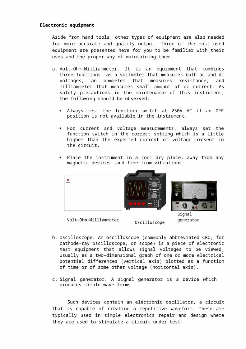
Electronic equipment
Aside from hand tools, other types of equipment are also needed for more accurate and quality output. Three of the most used equipment are presented here for you to be familiar with their uses and the proper way of maintaining them.
a. Volt-Ohm-Milliammeter. It is an equipment that combines three functions: as a voltmeter that measures both ac and dc voltages; an ohmmeter that measures resistance; and milliammeter that measures small amount of dc current. As safety precautions in the maintenance of this instrument, the following should be observed:
Always rest the function switch at 250V AC if an OFF position is not available in the instrument.
For current and voltage measurements, always set the function switch in the correct setting which is a little higher than the expected current or voltage present in the circuit.
Place the instrument in a cool dry place, away from any magnetic devices, and free from vibrations.
Volt-Ohm-Milliammeter Oscilloscope Signal generator
b. Oscilloscope. An oscilloscope (commonly abbreviated CRO, for cathode-ray oscilloscope, or scope) is a piece of electronic test equipment that allows signal voltages to be viewed, usually as a two-dimensional graph of one or more electrical potential differences (vertical axis) plotted as a function of time or of some other voltage (horizontal axis).
c. Signal generator. A signal generator is a device which produces simple wave forms.
Such devices contain an electronic oscillator, a circuit that is capable of creating a repetitive waveform. These are typically used in simple electronics repair and design where they are used to stimulate a circuit under test.
Oscilloscope and signal generator should be given regular checkup for at least once a week by connecting them to the power line. This will help prevent their components from having moisture that might cause trouble in their circuits.
In any activity involving skills, it is a standard procedure that you must always use the right tool or equipment properly needed for particular task. However, despite
CONSUMER ELECTRONICS SERVICING 12K to 12 – Technology and Livelihood Education

this reminder or caution, some students abuse the use of tools. The following are common faults that must be avoided:
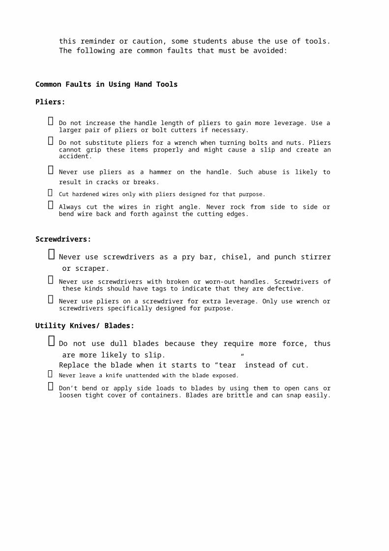
Common Faults in Using Hand Tools
Pliers:
Do not increase the handle length of pliers to gain more leverage. Use a larger pair of pliers or bolt cutters if necessary.
Do not substitute pliers for a wrench when turning bolts and nuts. Pliers cannot grip these items properly and might cause a slip and create an accident.
Never use pliers as a hammer on the handle. Such abuse is likely to result in cracks or breaks.
Cut hardened wires only with pliers designed for that purpose.
Always cut the wires in right angle. Never rock from side to side or bend wire back and forth against the cutting edges.
Screwdrivers:
Never use screwdrivers as a pry bar, chisel, and punch stirrer or scraper.
Never use screwdrivers with broken or worn-out handles. Screwdrivers of these kinds should have tags to indicate that they are defective.
Never use pliers on a screwdriver for extra leverage. Only use wrench or screwdrivers specifically designed for purpose.
Utility Knives/ Blades:
Do not use dull blades because they require more force, thus are more likely to slip. Replace the blade when it starts to “tear” instead of cut.
Never leave a knife unattended with the blade exposed.
Don’t bend or apply side loads to blades by using them to open cans or loosen tight cover of containers. Blades are brittle and can snap easily.
CONSUMER ELECTRONICS SERVICING 13K to 12 – Technology and Livelihood Education
How Much Have You Learned?
Self-Check 1.1
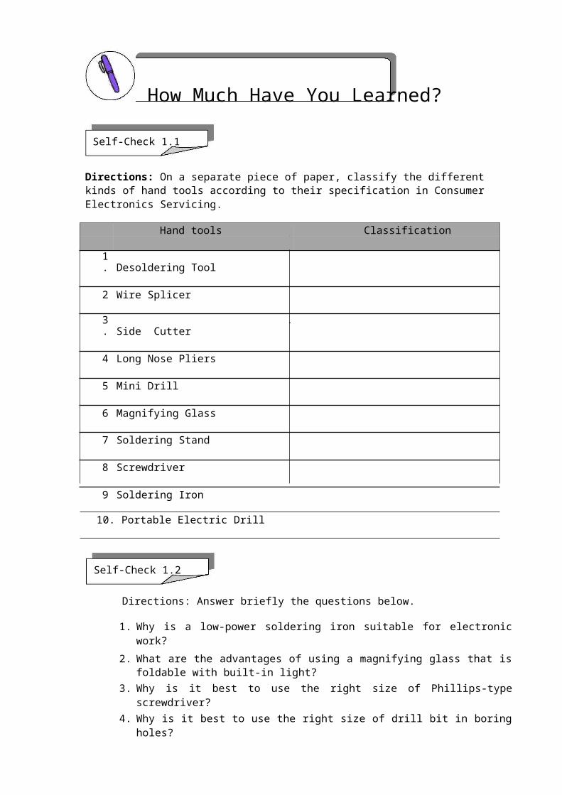
Directions: On a separate piece of paper, classify the different kinds of hand tools according to their specification in Consumer Electronics Servicing.
Hand tools Classification
1. Desoldering Tool
2 Wire Splicer
3. Side Cutter
4 Long Nose Pliers
5 Mini Drill
6 Magnifying Glass
7 Soldering Stand
8 Screwdriver
9 Soldering Iron
10. Portable Electric Drill
Self-Check 1.2
Directions: Answer briefly the questions below.
1. Why is a low-power soldering iron suitable for electronic work? 2. What are the advantages of using a magnifying glass that is foldable with built-in
light? 3. Why is it best to use the right size of Phillips-type screwdriver? 4. Why is it best to use the right size of drill bit in boring holes? 5. Why do you think is it best for a soldering iron to have its soldering stand?
Refer to the Answer Key. What is your score?
CONSUMER ELECTRONICS SERVICING 14K to 12 – Technology and Livelihood Education

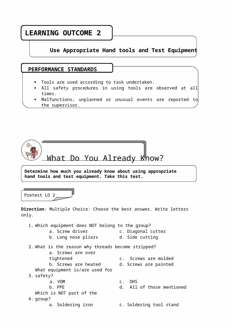
LEARNING OUTCOME 2
Use Appropriate Hand tools and Test Equipment
PERFORMANCE STANDARDS
Tools are used according to task undertaken. All safety procedures in using tools are observed at all times. Malfunctions, unplanned or unusual events are reported to the supervisor.
What Do You Already Know?Determine how much you already know about using appropriate hand tools and test equipment. Take this test.
Pretest LO 2
Direction: Multiple Choice: Choose the best answer. Write letters only.
1. Which equipment does NOT belong to the group?a. Screw driver c. Diagonal cutterb. Long nose pliers d. Side cutting
2. What is the reason why threads become stripped?a. Screws are over tightened c. Screws are moldedb. Screws are heated d. Screws are painted
3. What equipment is/are used for safety?a. VOM c. OHSb. PPE d. All of those mentioned
4. Which is NOT part of the group?a. Soldering iron c. Soldering tool standb. Desoldering tool d. Wire stripper
5. Which hand tool is used solely for cutting metals?a. Utility knife c. Magnifying glassb. Saw d. Paint brush
CONSUMER ELECTRONICS SERVICING 15K to 12 – Technology and Livelihood Education
What Do You Need To Know?Read Information Sheet 2.1 very well. Then find out how much you can remember and how much you learned by answering the Self-check.
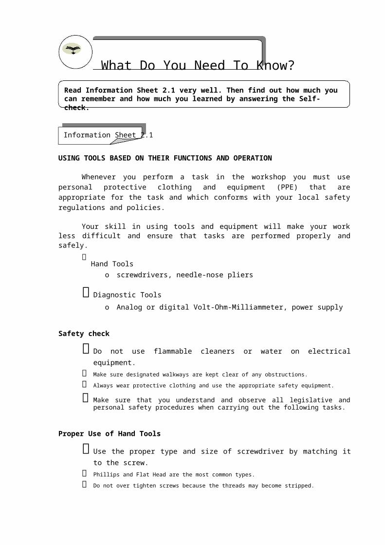
Information Sheet 2.1
USING TOOLS BASED ON THEIR FUNCTIONS AND OPERATION
Whenever you perform a task in the workshop you must use personal protective clothing and equipment (PPE) that are appropriate for the task and which conforms with your local safety regulations and policies.
Your skill in using tools and equipment will make your work less difficult and ensure that tasks are performed properly and safely.
Hand Tools
o screwdrivers, needle-nose pliers
Diagnostic Tools o Analog or digital Volt-Ohm-Milliammeter, power supply
Safety check
Do not use flammable cleaners or water on electrical equipment.
Make sure designated walkways are kept clear of any obstructions.
Always wear protective clothing and use the appropriate safety equipment.
Make sure that you understand and observe all legislative and personal safety procedures when carrying out the following tasks.
Proper Use of Hand Tools
Use the proper type and size of screwdriver by matching it to the screw. Phillips and Flat Head are the most common types.
Do not over tighten screws because the threads may become stripped.
In many types of work, hand tools are used every day. They make work easier and allow people to be more efficient. However, majority of students often fail to see the hazards these tools can introduce. In this module "Hand Tool Safety" shows workers how accidents can be significantly reduced by reviewing the various hazards that are associated with specific types of tools.
CONSUMER ELECTRONICS SERVICING 16K to 12 – Technology and Livelihood Education

How Much Have You Learned?Self-check 2.1
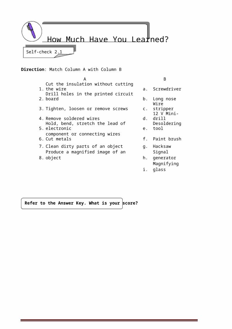
Direction: Match Column A with Column B
A B1. Cut the insulation without cutting the wire a. Screwdriver
2. Drill holes in the printed circuit board b. Long nose
3. Tighten, loosen or remove screws c. Wire stripper
4. Remove soldered wires d. 12 V Mini-drill
5. Hold, bend, stretch the lead of electronic e. Desoldering toolcomponent or connecting wires
6. Cut metals f. Paint brush
7. Clean dirty parts of an object g. Hacksaw
8. Produce a magnified image of an object h. Signal generator
i. Magnifying glass
Refer to the Answer Key. What is your score?
CONSUMER ELECTRONICS SERVICING 17K to 12 – Technology and Livelihood Education

How Do You Apply What You Have Learned?Show that you have learned something by doing this activity.
Operation Sheet 2.1
Instruction:
1. Do the following Operation Sheets:
a. Procedure in using a soldering iron b. Mounting and soldering of components on PCB c. Disassembly and assembly of the circuit
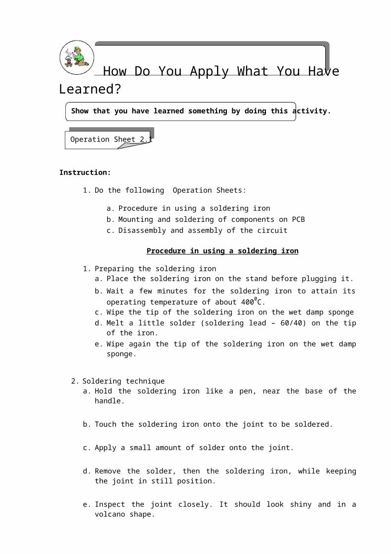
Procedure in using a soldering iron
1. Preparing the soldering iron a. Place the soldering iron on the stand before plugging it. b. Wait a few minutes for the soldering iron to attain its operating temperature of
about 4000C. c. Wipe the tip of the soldering iron on the wet damp sponge d. Melt a little solder (soldering lead – 60/40) on the tip of the iron. e. Wipe again the tip of the soldering iron on the wet damp sponge.
2. Soldering technique a. Hold the soldering iron like a pen, near the base of the handle.
b. Touch the soldering iron onto the joint to be soldered.
c. Apply a small amount of solder onto the joint.
d. Remove the solder, then the soldering iron, while keeping the joint in still position.
e. Inspect the joint closely. It should look shiny and in a volcano shape.
CONSUMER ELECTRONICS SERVICING 18K to 12 – Technology and Livelihood Education
Operation Sheet 2.2
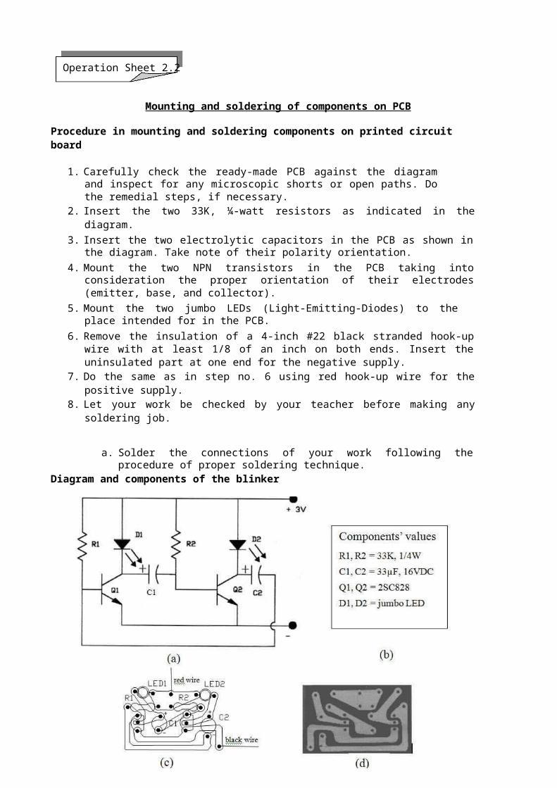
Mounting and soldering of components on PCB
Procedure in mounting and soldering components on printed circuit board
1. Carefully check the ready-made PCB against the diagram and inspect for any microscopic shorts or open paths. Do the remedial steps, if necessary.
2. Insert the two 33K, ¼-watt resistors as indicated in the diagram. 3. Insert the two electrolytic capacitors in the PCB as shown in the diagram. Take note
of their polarity orientation. 4. Mount the two NPN transistors in the PCB taking into consideration the proper
orientation of their electrodes (emitter, base, and collector). 5. Mount the two jumbo LEDs (Light-Emitting-Diodes) to the place intended for in the
PCB. 6. Remove the insulation of a 4-inch #22 black stranded hook-up wire with at least 1/8 of
an inch on both ends. Insert the uninsulated part at one end for the negative supply. 7. Do the same as in step no. 6 using red hook-up wire for the positive supply. 8. Let your work be checked by your teacher before making any soldering job.
a. Solder the connections of your work following the procedure of proper soldering technique.
Diagram and components of the blinker
Blinker circuit. (a) Schematic diagram (b) Parts list (c) Components’ lay out (top view) (d)Foil pattern on PCB (bottom view)
CONSUMER ELECTRONICS SERVICING 19K to 12 – Technology and Livelihood Education
Operation Sheet 2.3
Disassembly and assembly of the circuit
Desoldering
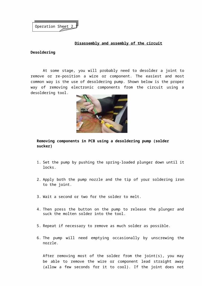
At some stage, you will probably need to desolder a joint to remove or re-position a wire or component. The easiest and most common way is the use of desoldering pump. Shown below is the proper way of removing electronic components from the circuit using a desoldering tool.
Removing components in PCB using a desoldering pump (solder sucker)
1. Set the pump by pushing the spring-loaded plunger down until it locks.
2. Apply both the pump nozzle and the tip of your soldering iron to the joint.
3. Wait a second or two for the solder to melt.
4. Then press the button on the pump to release the plunger and suck the molten solder into the tool.
5. Repeat if necessary to remove as much solder as possible.
6. The pump will need emptying occasionally by unscrewing the nozzle.
After removing most of the solder from the joint(s), you may be able to remove the wire or component lead straight away (allow a few seconds for it to cool). If the joint does not come apart easily, apply your soldering iron to melt the remaining traces of solder, at the same time pulling the joint apart, taking care to avoid burning yourself.
Be careful in desoldering to be sure that no component is damaged during the process.
CONSUMER ELECTRONICS SERVICING 20K to 12 – Technology and Livelihood Education

How Well Did You Perform?Find out by accomplishing the Scoring Rubric honestly and sincerely. Remember it is your learning at stake!
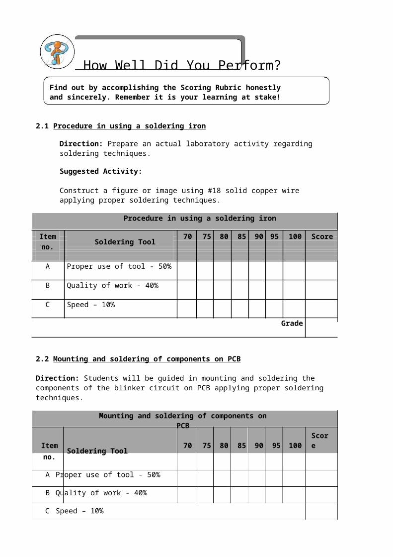
2.1 Procedure in using a soldering iron
Direction: Prepare an actual laboratory activity regarding soldering techniques.
Suggested Activity:
Construct a figure or image using #18 solid copper wire applying proper soldering techniques.
Procedure in using a soldering iron
Item Soldering Tool 70 75 80 85 90 95 100 Scoreno.
A Proper use of tool - 50%
B Quality of work - 40%
C Speed – 10%
Grade
2.2 Mounting and soldering of components on PCB
Direction: Students will be guided in mounting and soldering the components of the blinker circuit on PCB applying proper soldering techniques.
Mounting and soldering of components on PCB
Item Soldering Tool 70 75 80 85 90 95 100 Scoreno.
A Proper use of tool - 50%
B Quality of work - 40%
C Speed – 10%
Grade
CONSUMER ELECTRONICS SERVICING 21K to 12 – Technology and Livelihood Education
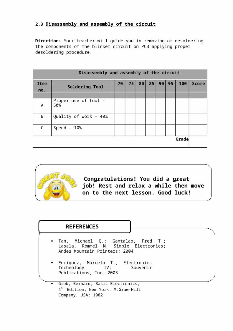
2.3 Disassembly and assembly of the circuit
Direction: Your teacher will guide you in removing or desoldering the components of the blinker circuit on PCB applying proper desoldering procedure.
Disassembly and assembly of the circuit
Item Soldering Tool 70 75 80 85 90 95 100 Scoreno.
A Proper use of tool - 50%
B Quality of work - 40%
C Speed – 10%
Grade
Congratulations! You did a great job! Rest and relax a while then move on to the next lesson. Good luck!
REFERENCES
Tan, Michael Q.; Gantalao, Fred T.; Lasala, Rommel M. Simple Electronics; Andes Mountain Printers; 2004
Enriquez, Marcelo T., Electronics Technology IV; Souvenir Publications, Inc. 2003
Grob, Bernard, Basic Electronics, 4th Edition; New York: McGraw-Hill Company, USA: 1982
CONSUMER ELECTRONICS SERVICING 22K to 12 – Technology and Livelihood Education

LESSON 2
Perform Mensuration and Calculations
LEARNING OUTCOMES:At the end of this Lesson, you are expected to do the following:
LO 1. select measuring instruments;LO 2. carry out measurements and calculations; andLO 3. maintain measuring instruments.
CONSUMER ELECTRONICS SERVICING 23
K to 12 – Technology and Livelihood Education

Definition of Terms
Ampere - basic unit of current
Current - the flow of electrons moving in a given direction
Electronic measuring instrument – a portable instrument used to measure electrical quantities such as current, voltage, and resistance
Ohmmeter - an electronic instrument used to measure resistance of a component or the entire circuit
Ohmmeter scale - section of the ohmmeter where the value of the resistance is being indicated
Range multiplier - a portion in the ohmmeter where the actual reading is multiplied by the range value
Resistance - the opposition to the flow of electrons
Resistor - an electronic component that is used to offer opposition to current in an electrical circuit
Resistor color coding - a scheme to determine the value of resistors by color bands printed on their bodies as code
Test Probes - connectors connected to terminals of the VOM and component’s terminals or test points in a circuit to be tested. They are oftentimes red and black in color
Tolerance - the fourth color in the 3-band color coding that indicates the percentage of deviation from its color coded value
Volt - basic unit of voltage
Voltage - an electrical pressure that pushes current to flow within a load through a conductor
Zero-ohm adjuster - part of the ohmmeter that is used in adjusting the pointer of the ohmmeter to zero before resistance measurements or continuity tests are made.
CONSUMER ELECTRONICS SERVICING 24K to 12 – Technology and Livelihood Education
LEARNING OUTCOME 1
Select measuring instrument
PERFORMANCE STANDARDS
Object or component to be measured is identified. Correct specifications are obtained from relevant
source. Appropriate measuring instrument is
selected in line with job requirement.
What Do You Already Know?Let us determine how much you already know about selecting measuring instrument. Take this test.
Pretest LO 1
Directions: Choose the best answer. Write the letter only.
1. Which component resists the flow of current in an electrical circuit?A) Capacitor B) Inductor C) Resistor D) Transistor
2. What kind of component is a resistor?A) Combined B) Discrete C) Integrated D) Hybrid
3. What color in the color coding scheme has an equivalent of 5 in the 2nd band?
A) Brown B) Green C) Red D) Yellow
4. What is the color of the tolerance representing ± 10%?A) Gold B) Black C) Orange D) Silver
5. What is the value of a resistor with the following colors : Green - Black- Silver- Gold?
A) 500 Ohms ±5% C) 5.0 Ohms ± 5%
B) 50 Ohms ± 5% D) 0.5 Ohm ± 5%
CONSUMER ELECTRONICS SERVICING 25K to 12 – Technology and Livelihood Education

What Do You Need To Know?
Read Information Sheet 1.1 very well then find out how much you can remember and how much you have learned by doing Self-Check.
Information Sheet 1.1
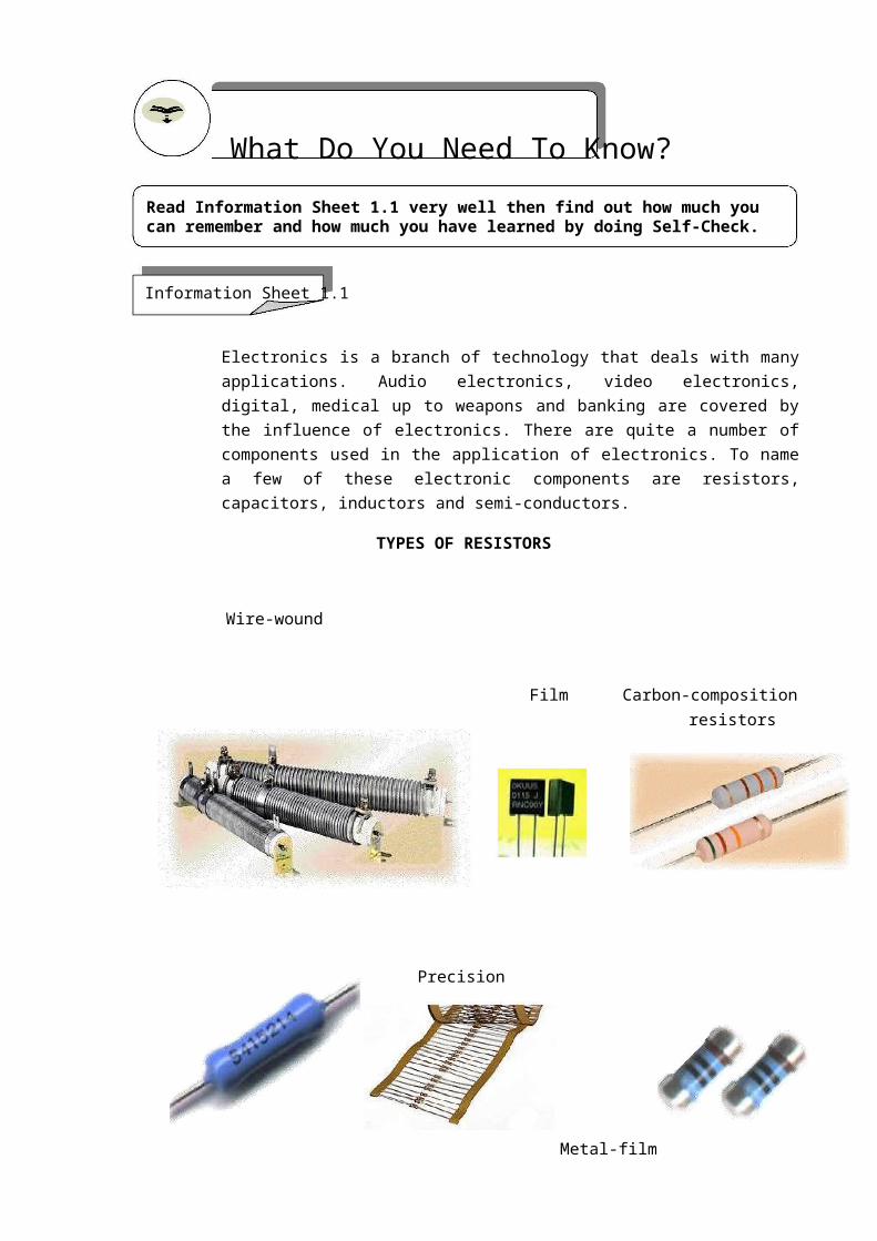
Electronics is a branch of technology that deals with many applications. Audio electronics, video electronics, digital, medical up to weapons and banking are covered by the influence of electronics. There are quite a number of components used in the application of electronics. To name a few of these electronic components are resistors, capacitors, inductors and semi-conductors.
TYPES OF RESISTORS
Wire-wound
Film Carbon-compositionresistors
Precision
Metal-film
Resistors in band
CONSUMER ELECTRONICS SERVICING 26K to 12 – Technology and Livelihood Education
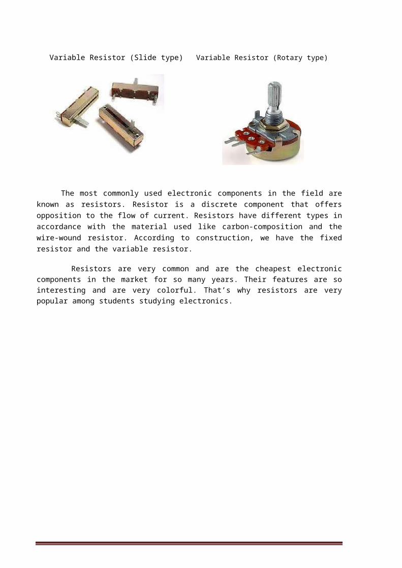
Variable Resistor (Slide type) Variable Resistor (Rotary type)
The most commonly used electronic components in the field are known as resistors. Resistor is a discrete component that offers opposition to the flow of current. Resistors have different types in accordance with the material used like carbon-composition and the wire-wound resistor. According to construction, we have the fixed resistor and the variable resistor.
Resistors are very common and are the cheapest electronic components in the market for so many years. Their features are so interesting and are very colorful. That’s why resistors are very popular among students studying electronics.
CONSUMER ELECTRONICS SERVICING 27K to 12 – Technology and Livelihood Education

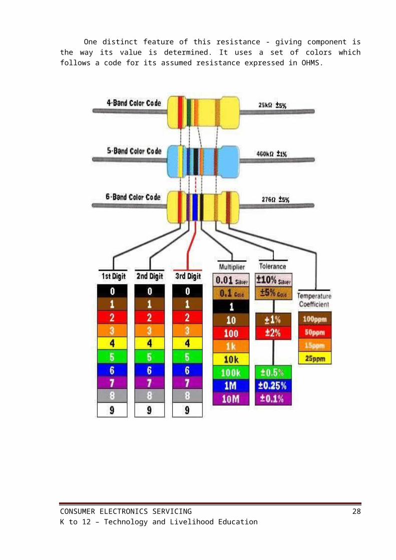
One distinct feature of this resistance - giving component is the way its value is determined. It uses a set of colors which follows a code for its assumed resistance expressed in OHMS.
CONSUMER ELECTRONICS SERVICING 28K to 12 – Technology and Livelihood Education
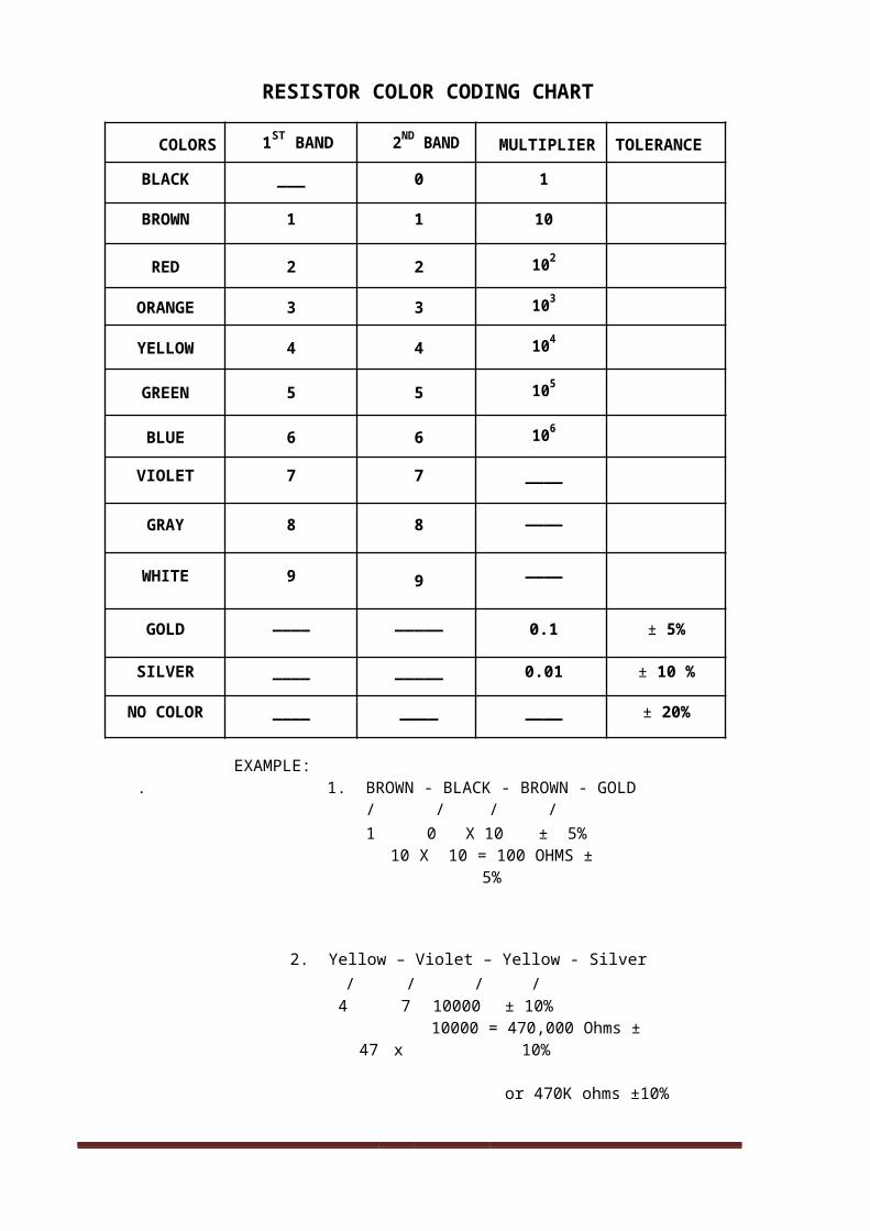
RESISTOR COLOR CODING CHART
COLORS 1ST BAND 2ND BAND MULTIPLIER TOLERANCE
BLACK ___ 0 1
BROWN 1 1 10
RED 2 2 102
ORANGE 3 3 103
YELLOW 4 4 104
GREEN 5 5 105
BLUE 6 6 106
VIOLET 7 7 ____
GRAY 8 8 ____
WHITE 9 9 ____
GOLD ____ _____ 0.1 ± 5%
SILVER ____ _____ 0.01 ± 10 %
NO COLOR ____ ____ ____ ± 20%
EXAMPLE:. 1. BROWN - BLACK - BROWN - GOLD
/ / / /1 0 X 10 ± 5%
10 X 10 = 100 OHMS ± 5%
2. Yellow – Violet – Yellow - Silver/ / / /
4 7 10000 ± 10%
47 x 10000 = 470,000 Ohms ± 10%
or 470K ohms ±10%
CONSUMER ELECTRONICS SERVICING 29K to 12 – Technology and Livelihood Education
How Much Have You Learned?
Self-Check 1.1
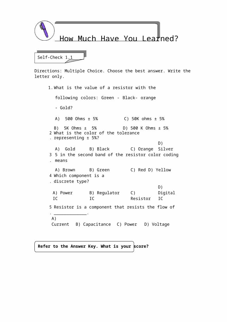
Directions: Multiple Choice. Choose the best answer. Write the letter only.
1. What is the value of a resistor with the following colors:
Green - Black- orange - Gold?
A) 500 Ohms ± 5% C) 50K ohms ± 5%
B) 5K Ohms ± 5% D) 500 K Ohms ± 5%
2. What is the color of the tolerance representing ± 5%?
A) Gold B) Black C) Orange D) Silver
3. 5 in the second band of the resistor color coding means
A) Brown B) Green C) Red D) Yellow
4. Which component is a discrete type?
A) Power IC B) Regulator IC C) Resistor D) Digital IC
5. Resistor is a component that resists the flow of _____________.
A) Current B) Capacitance C) Power D) Voltage
Refer to the Answer Key. What is your score?
CONSUMER ELECTRONICS SERVICING 30K to 12 – Technology and Livelihood Education
How Do You Apply What You Have Learned?Show that you learned something by doing this activity
Operation Sheet 1.1
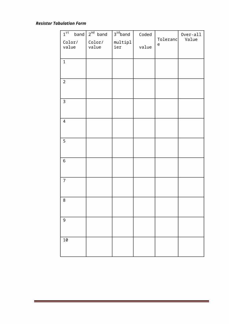
Materials:
10 pieces - Carbon resistors, 1 watt, assorted values
1 pc - Resistor Tabulation form
Procedure:
1. Arrange the resistors on a piece of styrofor in random manner.
2. Identify the colors of the resistors one by one and record them in the resistor tabulation form.
3. Compute for the resistance value of each resistor by following the color coding scheme.
4. Write the value of the resistance in the tabulation form.
5. Arrange the resistors in such a way that the value is in ascending manner.
CONSUMER ELECTRONICS SERVICING 31K to 12 – Technology and Livelihood Education

Resistor Tabulation Form
1st band 2nd band 3rdband Coded Over-all
Color/value Color/value multiplier value Tolerance Value
1
2
3
4
5
6
7
8
9
10
CONSUMER ELECTRONICS SERVICING 32K to 12 – Technology and Livelihood Education
How Well Did You Perform?
Find out by accomplishing the Scoring Rubric honestly and sincerely. Remember it is your learning at stake!
Find out by accomplishing the Scoring Rubrics honestly and sincerely. Remember it is your learning at stake
With perfect score of 10 ………………………….. 5
With 1 mistake …………………………………….. 4
With 2 – 3 mistakes…………………………………3
With 4 – 5 mistakes ……………………………….. 2
With more than 5 mistakes ………………………. 1
CONSUMER ELECTRONICS SERVICING 33K to 12 – Technology and Livelihood Education

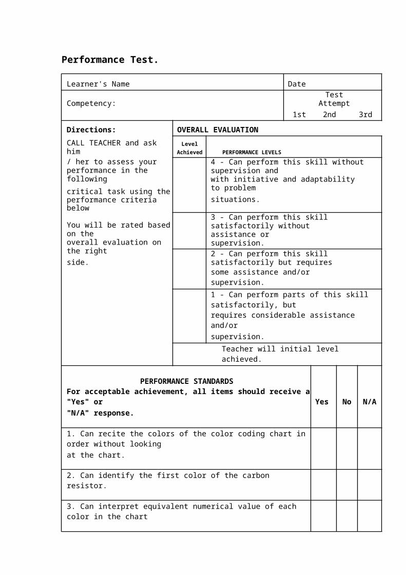
Performance Test.
Learner's Name Date
Competency: Test Attempt1st 2nd 3rd
Directions: OVERALL EVALUATION
CALL TEACHER and ask himLevel
Achieved PERFORMANCE LEVELS/ her to assess your
4 - Can perform this skill without supervision andperformance in the followingwith initiative and adaptability to problemcritical task using thesituations.performance criteria below
You will be rated based on the3 - Can perform this skill satisfactorily withoutassistance or supervision.
overall evaluation on the right2 - Can perform this skill satisfactorily but requiresside.some assistance and/or supervision.
1 - Can perform parts of this skill satisfactorily, butrequires considerable assistance and/orsupervision.
Teacher will initial level achieved.
PERFORMANCE STANDARDS
For acceptable achievement, all items should receive a "Yes" or Yes No N/A"N/A" response.
1. Can recite the colors of the color coding chart in order without lookingat the chart.
2. Can identify the first color of the carbon resistor.
3. Can interpret equivalent numerical value of each color in the chart
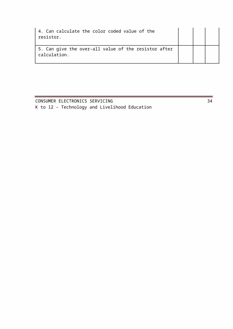
4. Can calculate the color coded value of the resistor.
5. Can give the over-all value of the resistor after calculation.
CONSUMER ELECTRONICS SERVICING 34K to 12 – Technology and Livelihood Education
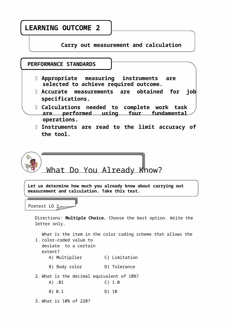
LEARNING OUTCOME 2
Carry out measurement and calculation
PERFORMANCE STANDARDS
Appropriate measuring instruments are selected to achieve required outcome.
Accurate measurements are obtained for job specifications.
Calculations needed to complete work task are performed using four fundamental operations.
Instruments are read to the limit accuracy of the tool.
What Do You Already Know?
Let us determine how much you already know about carrying out measurement and calculation. Take this test.
Pretest LO 2
Directions: Multiple Choice. Choose the best option. Write the letter only.
1. What is the item in the color coding scheme that allows the color-coded value todeviate to a certain extent?
A) Multiplier C) Limitation
B) Body color D) Tolerance
2. What is the decimal equivalent of 10%?A) .01 C) 1.0
B) 0.1 D) 10
3. What is 10% of 220?A) 210 C) 22
B) 2.2 D) 11
4. What Is the maximum deviation of a 220ohms + 10% tolerance?A) 230ohms C) 224 ohms
B) 242 ohms D) 236 ohms

CONSUMER ELECTRONICS SERVICING 35K to 12 – Technology and Livelihood Education
5. What is the minimum deviation of – 10% tolerance of the same resistor cited in no. 4?
A) 90 ohms C) 190 ohms
B) 198 ohms D) 210 ohms
What Do You Need To Know?
Read Information Sheet 2.1 very well then find out how much you can remember and how much you learned by doing Self-Check.
Information Sheet 2.1
Resistor color coded value is not absolute. The real resistance of the resistor is sometimes lower or higher than its color coded value but not to exceed its tolerance level.
Tolerance is the limit on how far the real value of the resistor can deviate from its color coded value. It can be more or less but subjected to a tolerable limit.
In the color coding chart there is a column for tolerance. Color gold is + or – 5%, silver is + or – 10 %, and the no color means + or – 20%.
Procedure in interpreting the tolerance of resistor
1. Identify the tolerance color of the resistor being analyzed. Assuming the color is gold which has a value of + or – 5%.
2. Convert the percentage into its decimal equivalent. 5% is equivalent to .05 3. Compute for the percentage of the color coded value. Assuming that the color
coded value is 100 ohms ± 5%. So 100 x .05 = 5
4. For the + side, add 5 to the color coded value of 100. 100 + 5= 105 ohms
That is the maximum deviation for that resistor. Beyond that, the resistor will not be fitted for the circuit which requires such tolerance.
5. For the – side, deduct 5 from the color coded value of 100. 100 – 5 = 95 ohms
That will be the minimum deviation for that particular resistor. Far beyond that the resistor will be considered to be defective.
6. Finally the value of the resistor with colors brown- black- brown – gold is 100 ohms with a deviation of +5 or -5. (95 ohms -105 ohms)
CONSUMER ELECTRONICS SERVICING 36K to 12 – Technology and Livelihood Education

How Much Have You Learned?Self-Check 2.1
Directions: Choose the best option. Write the letter only.
1. What is the minimum resistance of a 100 ohm resistor with 10% tolerance?
A) 90 ohms C) 190 ohms
B) 190 ohms D) 210 ohms
2. What Is the maximum value of a 220 ohm resistor with a + 10% tolerance?
A) 230ohms C) 224 ohms
B) 242 ohms D) 236 ohms
3. What is 10% of 220?
A) 210 C) 22
B) 2.2 D) 11
4. What is the decimal equivalent of 5%?
A) .01 C) 1.0
B) .05 D) 10
5. The band in the color coding scheme that permits the value to deviate to a certain extent?
A) Multiplier C) Limitation
B) Body color D) Tolerance
Refer to the Answer Key. What is your score?
CONSUMER ELECTRONICS SERVICING 37K to 12 – Technology and Livelihood Education
How Do You Apply What You Have Learned?Show that you learned something by doing this activity
Operation Sheet 2.1
Objective: To compute for the tolerance ceiling of carbon resistors.
Materials:
10pcs. Carbon resistors Paper and pencil
Procedure:
1. Arrange resistors as done in the first operation. 2. Identify the tolerance color and record them in the resistor
tabulation sheet. 3. Compute for the maximum value of the + tolerance. 4. Compute for the maximum value of the – tolerance.
RESISTOR TABULATION SHEET
Coded Maximum Minimum
Colors value Tolerance value value
CONSUMER ELECTRONICS SERVICING 38K to 12 – Technology and Livelihood Education

How Well Did You Perform?
Find out by accomplishing the Scoring Rubric honestly and sincerely. Remember it is your learning at stake!
With perfect score of 10 ………………………….5
With 1 mistake …………………………………….4
With 2 – 3 mistakes……………………………… 3
With 4 – 5 mistakes ………………………………2
With more than 5 mistakes ………………………1
Information Sheet 2.2
Resistor color coding gives us the color coded value of a given resistor as well as the maximum and minimum value as dictated by the tolerance but the actual resistance is still unknown to us. The actual value of the resistor and the recorded data will confirm the status of the resistor, whether good or defective.
OHMMETER
Ohmmeter is a measuring instrument used to determine the resistance of a component or equipment. This instrument is a great help in knowing the actual resistance of the resistors we use in the two operation sheets.
The commonly used ohmmeter in electro-electrical laboratories nowadays is embedded in a multi-function testing instrument called the (Volt-Ohm-Milliammeter ) VOM. For this discussion the VOM will be used but confined only to the ohmmeter section.
CONSUMER ELECTRONICS SERVICING 39K to 12 – Technology and Livelihood Education
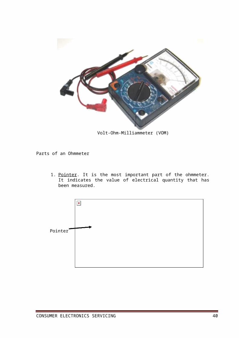
Volt-Ohm-Milliammeter (VOM)
Parts of an Ohmmeter
1. Pointer . It is the most important part of the ohmmeter. It indicates the value of electrical quantity that has been measured.
Pointer
CONSUMER ELECTRONICS SERVICING 40K to 12 – Technology and Livelihood Education

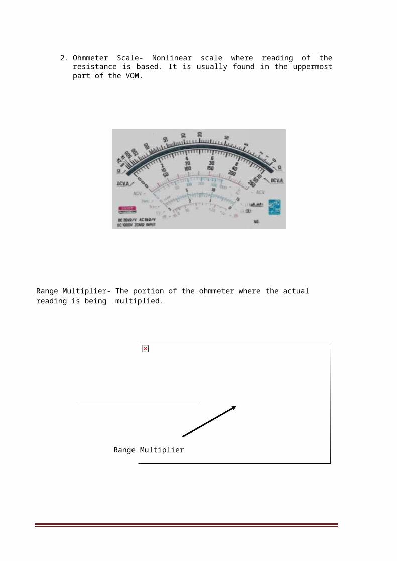
2. Ohmmeter Scale - Nonlinear scale where reading of the resistance is based. It is usually found in the uppermost part of the VOM.
Range Multiplier- The portion of the ohmmeter where the actual reading is being multiplied.
Range Multiplier
CONSUMER ELECTRONICS SERVICING 41K to 12 – Technology and Livelihood Education
Zero Ohm Adjustment – It is the portion of the ohmmeter where it is adjusted when the pointer of the ohmmeter fails to point to zero.
ZERO OHM ADJUST
Test Probe- It serves as the input portion of the ohmmeter. It has the Red test probe as negative while the black one is positive.
Test Probes
CONSUMER ELECTRONICS SERVICING 42K to 12 – Technology and Livelihood Education

PROCEDURE ON HOW TO INTERPRET RESISTANCE READING IN AN OHMMETER
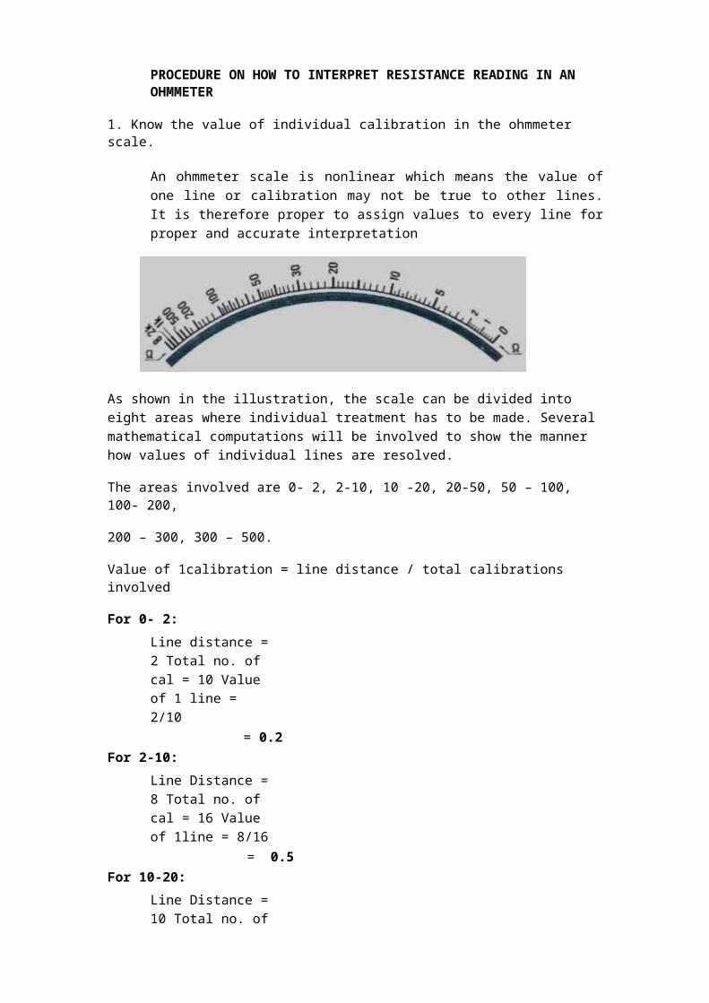
1. Know the value of individual calibration in the ohmmeter scale.
An ohmmeter scale is nonlinear which means the value of one line or calibration may not be true to other lines. It is therefore proper to assign values to every line for proper and accurate interpretation
As shown in the illustration, the scale can be divided into eight areas where individual treatment has to be made. Several mathematical computations will be involved to show the manner how values of individual lines are resolved.
The areas involved are 0- 2, 2-10, 10 -20, 20-50, 50 – 100, 100- 200,
200 – 300, 300 – 500.
Value of 1calibration = line distance / total calibrations involved
For 0- 2:Line distance = 2 Total no. of cal = 10 Value of 1 line = 2/10
= 0.2For 2-10:
Line Distance = 8 Total no. of cal = 16 Value of 1line = 8/16
= 0.5For 10-20:
Line Distance = 10 Total no. of cal = 10 Value of 1line= 10 /10
= 1
For 20 -50:Line Distance = 30 Total no. of cal = 15 Value of 1 line = 30/15
= 2.0
CONSUMER ELECTRONICS SERVICING 43K to 12 – Technology and Livelihood Education
For 50-100:Line Distance = 50 Total no. of cal = 10 Value of 1 line = 50/10
= 5.0For 100 – 200:
Line Distance = 100 Total no. of cal = 5 Value of 1 line = 100/5
= 20For 200-300:
Line Distance= 100 Total no. of lines = 2 Value of 1 line = 100/2
= 50
For 300–500:Line Distance = 200Total no. of cal= 2Value of 1 line = 200/2
= 100
2. Identify the appropriate range multiplier to be used Range multiplier is from R X 1, RX 10, R X 100, R X 1K, and R X 10K.
3. Connect the metallic part of the test probes and take note if the pointer points at zero. If not, adjust the zero ohm adjustment to zero.
4. Make the necessary resistance measurements.
CONSUMER ELECTRONICS SERVICING 44K to 12 – Technology and Livelihood Education

How Much Have You Learned?Self-Check 2.2
Directions: Choose the best answer. Write the letter only.
1. What is the instrument that is used to measure resistance?A) Ammeter C) Voltmeter
B) Ohmmeter D) Wattmeter
2. From what part of the ohmmeter do you derive resistance reading?A) Range Multiplier C) Test Probes
B) Reading Scale D) Pointer
3. What is the lowest range multiplier in an ohmmeter?A) RX 1 C) R X 100
B) R X 10 D) R X 1K
4. The reading scale of the ohmmeter is of what type?A) Horizontal C) Nonlinear
B) Linear D) Vertical
5. In what instrument can you find the ohmmeter?A) Ammeter C) DMM
B) Tube tester D) VOM
Refer to the Answer Key. What is your score?
CONSUMER ELECTRONICS SERVICING 45K to 12 – Technology and Livelihood Education
How Do You Apply What You Have Learned?Show that you learned something by doing this activity
Operation Sheet 2.2
Tools and Materials:
1 unit Ohmmeter
1 pair Long nose pliers
10 pieces assorted value carbon resistors
Directions: On a piece of paper (Resistor Tabulation Sheet), record the resistances of the 10 resistors following the procedure in resistance measurements. Compare the reading (measured value) with the color-coded value.
RESISTOR TABULATION SHEET
Color - Maximum Minimum Measuredcoded Tolerance RemarksValueColors Value Value Value
CONSUMER ELECTRONICS SERVICING 46K to 12 – Technology and Livelihood Education
How Well Did You Perform?
Find out by accomplishing the Scoring Rubric honestly and sincerely. Remember it is your learning at stake!
With perfect score of 10 ………………………….. 5
With 1 mistake …………………………………….. 4
With 2 – 3 mistakes…………………………………3
With 4 – 5 mistakes ………………………………...2
With more than 5 mistakes ………………………. 1
CONSUMER ELECTRONICS SERVICING 47K to 12 – Technology and Livelihood Education
LEARNING OUTCOME 3
Maintain measuring instruments
PERFORMANCE STANDARDS
Measuring instruments are handled properly to avoid damage.
Measuring instruments are cleaned before and after using
Proper storage of instruments is undertaken according to the manufacturer’s specifications and standard operating procedure.
Materials
What Do You Already Know?Let us determine how much you already know about maintaining measuring instrument. Take this test.
Pretest LO 3
Directions: Choose the best answer and write the letter only.
1. Which instrument serves as 3 measuring instruments in one?A) Audio Generator C) Signal Generator
B) Oscilloscope D) VOM
2. Which device produces simple wave forms?A) Audio Amplifier C) Signal tracer
B) VOM D) Signal Generator
3. Where is the function switch rested if an off position is not available In the VOM?A) 10VDC C) 100 VAC
B) 50 VAC D) 250 VAC

CONSUMER ELECTRONICS SERVICING 48K to 12 – Technology and Livelihood Education
4. Place instruments in a cool dry place and away from any ____________devices.
A) Audio amplifiers C) Magnetic devices
B) Other instruments D) Digital sources
5. What measuring instrument should be given regular check up by connecting it to power line?
A) Capacitor Tester C) Oscilloscope
B) DMM D) VOM
]
What Do You Need To Know?Read Information Sheet 3.1 very well then find out how much you can remember and how much you learned by doing Self-Check.
Information Sheet 3.1
Measuring instruments in electronics are confined only to analog testers and sometimes digital millimeter. Either way the maintenance of these instruments is a priority in all electronics laboratory rooms.
Electronic Measuring Instruments
Aside from hand tools, measuring instruments are also needed for more accurate and quality output. In this connection, three of the most used instruments are presented here for you to be familiar with their uses and the proper way of maintaining them.
CONSUMER ELECTRONICS SERVICING 49K to 12 – Technology and Livelihood Education

Volt-Ohm-Milliammeter. It is an equipment that combines three functions: as a voltmeter that measures both ac and dc voltages; an ohmmeter that measures resistance; and as a milliammeter that measures small amount of dc current. As safety precautions in the maintenance of this instrument, the following should be observed:
VOLT – OHM - Millimeter
Always rest the function switch at 250V AC, if an OFF position is not available in the instrument.
For current and voltage measurements, always set the function switch in the correct setting which is a little higher than the expected current or voltage present in the circuit.
Place the instrument in a cool dry place, away from any magnetic devices, and free from vibrations.
CONSUMER ELECTRONICS SERVICING 50K to 12 – Technology and Livelihood Education
Oscilloscope. An oscilloscope (commonly abbreviated CRO, for cathode-ray oscilloscope, or scope) is a piece of electronic test equipment that allows signal voltages to be viewed, usually as a two-dimensional graph of one or more electrical potential differences (vertical axis) plotted as a function of time or of some other voltage (horizontal axis).
OSCILLOSCOPE
Signal generator. A signal generator is a device which produces simple waveforms.
SIGNAL GENERATOR
CONSUMER ELECTRONICS SERVICING 51K to 12 – Technology and Livelihood Education
Such devices contain an electronic oscillator, a circuit that is capable of creating a repetitive waveform. These are typically used in simple electronics repair and design where they are used to stimulate a circuit under test.
Oscilloscope and signal generator should be given regular checkup for at least once a week by connecting them to the power line. This will help prevent their components from having moisture that might cause trouble in their circuits.
In any activity involving skills, it is a standard procedure that you must always use the right tool or equipment properly needed for particular task. However, in spite of this reminder or caution, some students abuse the use of tools.
How Much Have You Learned?Self-Check 3.1
Directions: Choose the best answer and write the letter only.
1. What is the instrument that serves as 3 measuring instruments in one?
A) Audio Generator C) Signal Generator
B) Oscilloscope D) VOM
2. What is a device which produces simple wave forms?A) Audio Amplifier C) Signal tracer
B) VOM D) Signal Generator
3. Where is the function switch rested if an off position is not available in the VOM?A) 10VDC C) !00 VAC
B) 50 VAC D) 250 VAC
4. Place instruments in a cool dry place and away from any ____________ devices.A) Other instruments C) Magnetic devices
B) Audio amplifiers D) Digital sources
5. What measuring instrument should be given regular checkup by connecting them to power line?
A) Capacitor Tester C) Oscilloscope
B) DMM D) VOM
Refer to the Answer Key. What is your score?
CONSUMER ELECTRONICS SERVICING 52K to 12 – Technology and Livelihood Education

Congratulations! You did a great job! Rest and relax a while then move on to the next lesson. Good luck!
REFERENCES
Enriquez, Marcelo T., Electronics Technology IV; Souvenir Publications, Inc. 2003
Grob, Bernard, Basic Electronics, 4th Edition; New York: McGraw-Hill Company, USA: 1982
Tan, Michael Q.; Gantalao, Fred T.; Lasala, Rommel M. Simple Electronics; Andes Mountain Printers; 2004
CONSUMER ELECTRONICS SERVICING 53K to 12 – Technology and Livelihood Education
LESSON 3
Prepare and Interpret Technical Drawings
LEARNING OUTCOMES:At the end of this Lesson, you are expected to do the following:
LO 1. identify different kinds of technical drawings; LO 2. interpret technical drawing; andLO 3. prepare/ make changes on electrical/ electronic schematics and diagrams.

CONSUMER ELECTRONICS SERVICING 54K to 12 – Technology and Livelihood Education

Definition of TermsAC voltage - a voltage in which the polarity alternates
Anode - the positive electrode or terminal of a device. The “P” material of a diode
Bridge Rectifier - a circuit using four diodes to provide full-wave rectification. It converts AC voltage to a pulsating DC voltage
Calibration – used to adjust the correct value of a reading with comparison to a standard value
Color Code - set of colors used to indicate value of a component
DC Power Supply – converts alternating current to direct current power source
Diode - a two terminal device that conducts in only one direction
Full Wave Rectifier - the rectifier that makes use of the full ac wave in both positive and negative half cycles
Fuse - a device in the current path that melts or breaks when current protective exceeds a predetermined maximum value
Half Wave Rectifier - a diode rectifier that converts AC to pulsating DC by eliminating either the negative or positive alternation of each input AC cycle
Leakage - small undesirable flow of current through an insulator or dielectric
Light Emitting Diode - a semiconductor diode that converts electric energy into electromagnetic radiation at a visible and near infrared frequencies when its PN junction is forward bias
Output - terminal at which a component, circuit or piece of equipment delivers current, voltage or power
Power Supply - electrical equipment used to deliver either AC or DC voltage
Primary - first winding of a transformer winding that is connected to the source as opposed to secondary which is a winding connected to a load
Printed Circuit Board (PCB) - insulating board containing conductive tracks forcircuit connections
Rectification - process that converts alternating current to direct current
Rectifier - diode circuit that converts AC to pulsating DC
CONSUMER ELECTRONICS SERVICING 55K to 12 – Technology and Livelihood Education

Regulated Power Supply - power supply that maintains a constant output voltage under changing load condition
Rotary Switch - electromechanical device that has a rotating shaft connected to one terminal capable of making, breaking a connection to one or more other terminals
Schematic Diagram - illustration of an electrical or electronic circuit with the components represented by their symbol
Secondary - output winding of a transformer winding that is connected to a load
Short Circuit - Low resistance connection between two points in a circuit typically causing excessive current and overheating
Solder - metallic alloy used to join two metal surfaces
Soldering Iron - tool with an internal heating element used to heat surfaces being soldered where the solder becomes molten
Substrate - mechanical insulating support upon which a device is fabricated
Switch - electrical device having two states, ON (closed) or OFF (open)
Test - sequence of operations intended to verify the correct operation or malfunctioning of a piece of equipment or system
Transformer - inductor with two or more windings
Troubleshooting - systematic approach to locate the cause of a fault in an electronic circuit or system
Volt-Ohm-Milliammeter - known as a multitester. A test equipment used to check AC, DC voltages, current in a circuit and resistance of any components out of the circuit
CONSUMER ELECTRONICS SERVICING 56K to 12 – Technology and Livelihood Education
LEARNING OUTCOME 1
Identifying different kinds of technical drawings
PERFORMANCE STANDARDS
Correct technical drawing is selected according to job requirements.
Technical drawings are segregated in accordance with the types and kinds of drawings.
What Do You Already Know?Let us determine how much you already know about identifying different kinds of technical drawings. Take this test.
Pretest LO 1
DIRECTIONS: Write the letter of the best answer on the space provided for before each
number. Use another sheet of paper for your answer.
______ 1. A drawing instrument consisting of two parts namely the stock and the blade,
joined together at right angles to each other by means of screws.
A. L-square C. T-square
B. Try square D. Protractor
______ 2. It is a combination of T-squares, scales, set squares, and protractors attached to
a drawing board.
A. Drafter C. Drawing set
B. Electronic template D. French curve
______ 3. This device includes symbols for electronic and electrical design that can be traced using a drawing pencil.
A. Triangular rule C. French curve
B. Electronic manual D. Electronic template
CONSUMER ELECTRONICS SERVICING 57K to 12 – Technology and Livelihood Education

______ 4. It is a smooth board usually rectangular in shape provided with perfectly straight edge which is used as working edge on which the T-square is
moved while making drawings.
A. Drawing board C. T-square
B. Breadboard D. Set of squares
_______ 5. A drawing instrument with two legs hinged at one end and is used for
drawing circles and arcs of circles.
A. Drafting pen C. Technical pen
B. Compass D. Protractor
Criteria for Evaluating Results of Pre-Test
100%-skip the Learning Outcome and proceed to the next Learning Outcome
99%-below – Go through the Learning Outcome
What Do You Need To Know?Read Information Sheet 1.1 very well then find out how much you can remember and how much you learned by doing Self-check 1.1.
Information Sheet 1.1
When you purchase a brand new appliance or equipment, it is very important that a diagram is included with the product to insure that there will be a reference material in case the appliance or equipment becomes defective. Shown in Fig. 1-1a is the schematic diagram of a 1-watt stereo audio amplifier, while Fig. 1-1b is its pictorial diagram.
CONSUMER ELECTRONICS SERVICING 58K to 12 – Technology and Livelihood Education

Fig. 1-1a. Schematic diagram of the 1-watt stereo amplifier.
Fig. 1-1b. Pictorial diagram of the 1-watt stereo amplifier.
CONSUMER ELECTRONICS SERVICING 59K to 12 – Technology and Livelihood Education

To produce a quality and marketable electronic diagram, you have to follow the Electronic Drafting Standards which is the process of illustrating various kinds of circuits and wiring systems.
The most common graphical languages used in the illustration of components in circuits and wiring systems are block, schematic, wiring, and pictorial diagrams.
Most symbols that you will encounter in laying out electronic diagrams are accepted as standard, but in some cases some manufacturers modify symbols and practices to suit a particular industrial policy while others use their own symbols to represent unique or special component and devices.
Do you know that electronic symbols and their use in conjunction with
recommended drafting practices have been developed through the years, and have been standardized by a number of different organizations? Among these are the American National Standards
Institute (ANSI), the Electronics Industries Association (IEA), the Institute of Electrical and Electronics Engineers (IEEE), and the International Electrotechnical Commission (IEC).
CONSUMER ELECTRONICS SERVICING 60K to 12 – Technology and Livelihood Education
Schematic Symbols of Electronic Components
Some of the electronic symbols that were mentioned earlier are shown in Fig. 1-2. You can use several electronic templates shown in Fig. 1-3 to help you in drawing these symbols.
Fig. 1-2. Schematic Symbols of Electronic Components.
Fig. 1-3. Electronic templates
Drawing instruments and their uses
Drawing instruments are used in preparing accurate drawings. Quality drawing instruments can produce accurate and good and presentable drawings. Below is a list of some of the most common used drawing instruments and materials in electronic drafting.
CONSUMER ELECTRONICS SERVICING 61K to 12 – Technology and Livelihood Education
1. Drawing board. A smooth board usually rectangular in shape provided with perfectly straight edge which is used as working edge on which the T-square is moved while making drawings.
2. T-square. A T-square consists of two parts namely the stock and the blade joined together at right angles to each other by means of screws. The stock is made to slide along the working edge and the blade moves on the drawing board. The working edge of a T-square is used to draw parallel lines, vertical lines or inclined lines at 30 or 60 degrees.
3 the uses andprotractors are
top end of the
CONSUMER ELECTRONICS SERVICING 62K to 12 – Technology and Livelihood Education
4. Set squares. Set squares are generally made from plastic material. They are triangular in shape with one corner, a triangle. A pair of set squares (30o- 60o) and 45o. They are used to draw lines at 30o, 60o and 45o to the vertical or horizontal.
5. Protractor. Protractors are used to mark or measure angles between 0 and 180o. They are semicircular in shape and are made of plastic. Protractors with circular shape are capable of marking and measuring 0 to 360 o are also available in the market.
CONSUMER ELECTRONICS SERVICING 63K to 12 – Technology and Livelihood
6. Drawing pencils. The accuracy and appearance of a drawing depends on the quality of pencil used to make drawing. The grade of a pencil lead is marked on the pencil. HB denotes medium grade. Increase in hardness is shown by the value put in front of H such as 2H, 3H, etc. Softer pencils are marked as 2B, 3B, and 4B etc. A pencil marked 3B is softer than 2B and pencil marked 4B is softer than 3B and so on. Beginning of a drawing may be made with H or 2H. For lettering and dimensioning, H or HB pencils are used.
7. Compass. A compass is used for drawing circles and arcs of circles. The compass has two legs hinged at one end. One of the legs has pointed needle fitted at the lower end whereas the other end has provision for inserting pencil lead.
8. Drawing pins and clips. These are used to fix the drawing sheet on the drawing board.
K to
9. Electronic templates include symbols for electronic and electrical design that can be traced using a drawing pencil.
CONSUMER ELECTRONICS SERVICING 65K to 12 – Technology and Livelihood Education
How Much Have You Learned?Self-Check 1.1
DIRECTIONS: Draw at least five (5) drawing instruments, describe and give the function of each.
Drawing instrument Description Use
Refer to the Answer Key. What is your score?
CONSUMER ELECTRONICS SERVICING 66K to 12 – Technology and Livelihood Education
What Do You Already Know?Let us determine how much you already know about the use farm tools and equipment. Take this test.
Pretest LO 2.1
Directions: Match the electronic and electrical symbols in Column A with the corresponding descriptions in column B. Write the letter of your answer on the space provided before each number.
Column A Column B
A. Capacitor______ 1.
B. Transistor
______ 2.
C. Transformer______ 3.
D. Fuse
______ 4.
______ 5.
E. Resistor
F. Diode
CONSUMER ELECTRONICS SERVICING 67K to 12 – Technology and Livelihood Education

What Do You Need To Know?
Read Information Sheet 1.2 very well then find out how much you can remember and how much you learned by doing Self-check 1.2.
Information Sheet 2.1
Resistor
A resistor is a device with a known value of resistance. Its main function is to reduce voltage and to limit the flow of current in a circuit. This resistance is actually the opposition that a component or material offers to the flow of current.
Resistance may or may not be useful in circuit/s. When too much current passes through a conductor, (solid, liquid, gas through which electrons pass easily) the resistance of the conductor may cause it to become hot. This, in turn, can create a fire hazard or cause the conductor to burn out. In this case, it is not desirable. In other cases, when it is placed intentionally in the circuit, it performs its specific task.
Symbol of Resistor
Fixed Variable
Fixed Resistors
It is a single value resistance, which remains the same under the normal condition. The two common kinds of fixed resistors are carbon resistor and film-type resistor.
Carbon Resistor Film Resistor
CONSUMER ELECTRONICS SERVICING 68K to 12 – Technology and Livelihood Education
Variable Resistor
Variable resistors are used when it is necessary to change the amount of resistance in a circuit. There are two common variable resistors, the potentiometer and rheostat. Generally a potentiometer is generally has carbon resistive element while the rheostat is generally made of resistance wire.
Potentiometer Rheostat
Both devices have a sliding arm that brings into contact with the resistance element. In most variable resistors the arm is attached to the shaft that can be adjusted
CONSUMER ELECTRONICS SERVICING 69K to 12 – Technology and Livelihood Education

A potentiometer is commonly used as control device. It can be used to vary the value of voltage applied to a certain circuit such as in the amplifier, television, and different kinds of meter circuit.
Resistor Power Rating
Power rating of resistors changes with their sizes, the bigger the resistor the greater the wattages and the smaller the resistor the lesser the wattage. Different sizes of resistors are shown below which are drawn to the exact proportion.
1/8W 1/4W 1/2W 1W 2W5W
A capacitor is a device that consists essentially of two conducting surfaces separated by a dielectric material like air, paper, mica, ceramic, glass, or Mylar. It makes it possible to store electric energy. Electrons are detained within a capacitor. This, in effect, is stored electricity. It is known as electrical potential or an electrostatic field. Electrostatic field hold electrons. When the increase of electrons becomes great enough, the electrical potentials are now ready to be discharged.
The component is designed intentionally to have a definite amount of capacitance. This capacitance is a property that exists whenever insulating material permits the storage of electricity. It is measured in Farad (F) micro Farad (µF), nano Farad (nF), and picoFarad (pF).
Characteristics of a Capacitor:
1. It can store electric charge even though the voltage source is already disconnected.
2. It can discharge electrical voltages.
Symbols of Capacitor
OR
Fixed Variable Polarized
CONSUMER ELECTRONICS SERVICING 70K to 12 – Technology and Livelihood Education
Common Types of Fixed CapacitorAluminum Electrolytic Capacitors (polarized)
Axial Leads Radial Leads Computer Grade Snap Mount Twist Lock Surface Mount
Tantalum Capacitors (polarized)
Solid Tantalum Solid Tantalum Foil Tantalum( Axial Leads ) ( Radial Leads ) ( Axial Leads ) Wet Tantalum Surface Mount
Dipped Tantalum
Ceramic Capacitors
Dip guard Monolithic Monolithic Disc
(Axial Leads) (Radial Leads)
Surface Mount
Film Capacitors
Polyester
(Axial Leads) Polyester Polypropylene Polypropylene Polystyrene
(Radial Leads) (Axial Leads) (Radial Leads) (Axial Leads)
CONSUMER ELECTRONICS SERVICING 71K to 12 – Technology and Livelihood Education

Variable capacitors used as tuning capacitor for radio receivers
1. Semiconductor Diodes
2. Bipolar Junction Transistors (BJT)
Rectifier ZenerLED
PNPNPN
Pictorial Symbol
CONSUMER ELECTRONICS SERVICING 72
K to 12 – Technology and Livelihood Education

3. Integrated Circuit (IC)
Pictorial Package
CONSUMER ELECTRONICS SERVICING 73K to 12 – Technology and Livelihood Education
How Much Have You Learned?
Self-Check 2.1
DIRECTIONS: Draw the schematic symbol and physical appearance of the following electronic components and give the function(s) of each (Table 1-1).
Table 1-1 Electronic Components
Type / Symbol Actual / Physical appearance Uses / Application
1. NPN Transistor
2. Zener diode
3. Polarized capacitor
4. Light-Emitting
Diode (LED)
5. PNP transistor
6. Battery
7. Variable capacitor
8. Potentiometer
Refer to the Answer Key. What is your score?
CONSUMER ELECTRONICS SERVICING 74K to 12 – Technology and Livelihood Education

LEARNING OUTCOME 2
Interpret Technical Drawings
PERFORMANCE STANDARDS
Components, assemblies or objects are recognized as required. Dimensions of the key features of the objects depicted in the drawing are
correctly identified. Symbols used in the drawing are identified and interpreted correctly. Drawings are checked and validated against job requirements or equipment in
accordance with standard operating procedure.
What Do You Already Know?Let us determine how much you already know about interpreting technical drawings. Take this test.
Pretest LO 2
Directions: Answer the following questions. Write the letter of the best answer.
1. A geometric figure usually used to represent a stage in a block diagram.A. Rectangle C. PentagonB. Circle D. Hexagon
2. It is the process of illustrating various kinds of circuits and wiring systems.A. Reference designation C. Freehand drawingB. Electronic Drafting D. Mechanical drawing
3. It shows the relationship between the various component groups or stages in the operation of the circuit.
A. Wiring diagram C. Pictorial diagramB. Block diagram D. Schematic diagram
4. Another name for connection diagram.A. Wiring diagram C. pictorial diagramB. Block diagram D. schematic diagram
CONSUMER ELECTRONICS SERVICING 75K to 12 – Technology and Livelihood Education
5. It is a picture or a sketch drawn to show the component of a circuit and how These components are connected together.
A. Wiring diagram C. Pictorial diagram
B. Block diagram D. Schematic diagram
Criteria for Evaluating Results of Pre-Test
100%-skip the Learning Outcome and proceed to the next Learning Outcome
99%-below – Go through the Learning Outcome
What Do You Need To Know?Read Information Sheet 2.1 very well then find out how much you can remember and how much you learned by doing Self-check 2.1.
Information Sheet 2.1
All electronic circuits from the simplest to the most complex design need diagrams to be used as reference in designing, modifying, and troubleshooting the circuit. The most common used electronic diagrams are schematic, pictorial, wiring, and block diagrams. Each one of these diagrams has its own unique characteristics in presenting the circuit. The different diagrams that you should be familiar with are the following:
Pictorial diagram - It shows the pictures of the actual components and wiring connections although it does not provide the exact size of components. It shows exact shape in proportion to the actual component or device.
CONSUMER ELECTRONICS SERVICING 76K to 12 – Technology and Livelihood Education

Pictorial Diagram of a Regulated Power Supply
Block Diagram – This form usually uses block of squares, rectangles or triangles to represent components, group of components or units of equivalent. Block diagrams are particularly used to represent internal components of an integrated circuit.
POWER DIODES OR
RECTIFIERS FILTER CIRCUIT REGULATOR
Block Diagram of a Regulated Power Supply
Schematic diagram – A diagram that shows the components used in their interconnection. Each graphic symbol is also accompanied with a reference designation to distinguish it from other similar symbols. It does not illustrate the physical size, shape or chassis location of the component parts and devices.
CONSUMER ELECTRONICS SERVICING 77
K to 12 – Technology and Livelihood Education
Schematic Diagram of a Regulated Power Supply (power transformer is NOT shown)
Wiring diagram – A diagram that shows wiring connection in a simplified, easy to follow manner. It may show either internal or external connections or both and is usually drawn as simple as possible to trace out the connection of a circuit. The components of the circuit are identified by name or are represented by means of pictorial illustrations that do not follow any well-defined standard form.
Wiring diagram of a selector switch for different input multi-media equipment
CONSUMER ELECTRONICS SERVICING 78K to 12 – Technology and Livelihood Education
How Much Have You Learned?Self-Check 2.1
DIRECTIONS: Shown below are different electronic diagrams. Write the name of the diagram in the space provided for at the bottom of each diagram.
1.______________________ 2.______________________
3.______________________
4.______________________ 5.______________________
Refer to the Answer Key. What is your score?
CONSUMER ELECTRONICS SERVICING 79K to 12 – Technology and Livelihood Education

LEARNING OUTCOME 3
Prepare electronic diagrams
PERFORMANCE STANDARDS
Electrical/ electronic schematic diagrams are drawn and correctly identified. Correct drawings are identified, equipment are selected and used
in accordance with job requirements
What Do You Already Know?Let us determine how much you already know about preparing electronic diagrams. Take this test.
Pretest LO 3
Directions: Answer the following questions. Encircle the letter of the best answer.
1. If the Greek letter Omega (Ω) appears in a schematic diagram, the component value being represented is a
A. Capacitor C. Transformer
B. Transistor D. Resistor
2. The labels of a capacitor C1A and C1B in a diagram are examples of _____.
A. Designated letters C. Subscript letters
B. Suffix letters D. Coefficient letters
3. These types of lines are used on schematic diagrams to show a mechanical linkage between components.
A. Dashed lines C. Thick linesB. Medium lines D. Thin lines
CONSUMER ELECTRONICS SERVICING 80K to 12 – Technology and Livelihood Education
4. One of these is NOT given in a schematic diagram A. Wiring specifications C. Actual appearance of components
B. Point-to-point resistance values D. Operating instructions
5. The symbols on a schematic diagram are arranged so that the diagram can be “read” in this manner.
A. Top to bottom C. Right to leftB. Bottom to top D. Left to right
Criteria for Evaluating Results
100%-skip the Learning Outcome and proceed to the next Learning Outcome
99%-below – Go through the Learning Outcome
What Do You Need To Know?
Read Information Sheet 3.1 very well then find out how much you can remember and how much you learned by doing Self-check 3.1.
Information Sheet 3.1
One of the features of a quality electronic diagram is its appearance with simplicity in design and easy-to-understand layout. To achieve this, you have to follow the following standards in laying out electronic diagrams.Rules for Drawing Symbols
Recommended practices to be used in the application of symbols to a circuit diagram are listed below.
1. The position of a symbol on a diagram does not affect its meaning.
2. The weight of a line used in drawing a symbol does not affect its meaning. In some cases, a heavier line may be used to emphasize a particular symbol.
3. A given symbol may be drawn in any size that is suitable for use in any particular diagram. However, when a symbol is enlarged or reduced in size, it should be drawn in proportion to the rest of the drawing.
CONSUMER ELECTRONICS SERVICING 81K to 12 – Technology and Livelihood Education

4. If necessary for contrast, some symbols may be drawn smaller or larger than other symbols on a diagram. However, for simplicity, it is recommended that not more than two different sizes of symbols be used on any one diagram.
5. In general, a connecting line should be brought to a symbol either vertically or horizontally, but a connecting line brought to a symbol at an angle has no particular significance unless otherwise noted.
6. The arrowhead of a symbol may be open ( ) or closed ( unlessotherwise noted.
7. The standard symbol for terminal (o) may be added to any symbol. But when this is done, the terminal symbol should not be considered a part of the symbol itself.
Reference Designations
The symbols used to represent various components on a circuit diagram are most often accompanied by a combination of letters that identify the components but are not themselves a part of the symbol (Table 3-1).
Table 3-1. Reference Designations of Electronic Components
Components Class Designation Letter(s)
Capacitor C
Diode D
Resistor R
Switch S or SW
Transformer T
Transistor Q or TR
When more than one symbol of a specific type of component appears on a diagram, the letter (or letters) is followed by numbers that identify the components. These combinations of letters and numbers are referred to as reference designations (Fig. 3-1).
CONSUMER ELECTRONICS SERVICING 82K to 12 – Technology and Livelihood Education
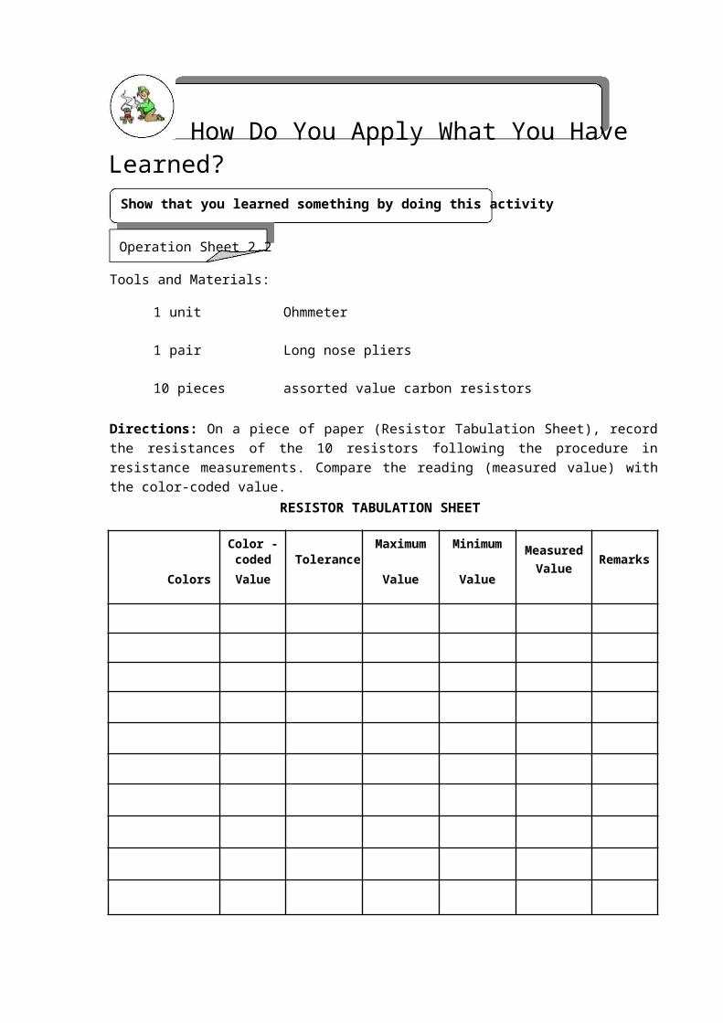
Fig. 3-1. Recommended methods of indicating reference designations and component values.
Numerical Values of Components
When details of the type, rating or value of a particular component are to be given on a diagram, this information is placed adjacent to the symbol or is given by means of notes accompanying the diagram. For example, resistance and capacitance values are indicated as shown in Fig. 3-1. In this scheme, the symbol Ω for ohms and the abbreviations µF and pF for capacitance values are usually omitted and are instead replaced by notes such as the following:
1. All resistors expressed in ohms unless otherwise indicated. 2. All capacitors expressed in microfarads unless otherwise indicated.
A resistance value of 1,000 ohms or more is most often expressed in terms of Kilohm (K) or Meghm (M) units. Thus a resistance of 4,700 ohms is written as 4.7K, while a resistance of 270,000 ohms may be written as 270K or as 0.27M. The comma used when writing a 4-digit number such as 4,700 is not used when such a number is given on a diagram.
Capacitance values of 1 through 9,999 picofarads are usually expressed in picofarad units. Capacitance values greater than 10,000 picofarads should be expressed in microfarad units.
Suffix Letters
Suffix letters are used to identify separate parts of a unit upon a diagram when such components appear as a single, enclosed unit as shown in Fig. 3-2. C1A and C1B are the suffix letters used in the diagram.
CONSUMER ELECTRONICS SERVICING 83K to 12 – Technology and Livelihood Education

C1A C1B
Fig. 3-2. Two capacitors are enclosed in one unit.
Layout
The layout or form of a diagram should show the main features prominently. The parts of a diagram should be carefully spaced to provide an even balance between blank spaces and lines. Enough blank space should be left in the areas near symbols to avoid crowding any necessary notes or reference information (Fig. 3-3).
Fig. 3-3. Schematic diagram of an audio amplifier.
Line Thickness
As with other types of diagrams, a schedule of line weights or line conventions is used in drawing electrical and electronics diagrams. The standard line conventions used in the preparation of these diagrams are shown in Table 3-2.
CONSUMER ELECTRONICS SERVICING 84K to 12 – Technology and Livelihood Education
Table 3-2. Line thickness
Line application Line thickness
For general useMedium
Mechanical connection, shielding, and future Mediumcircuits line
Bracket-connecting dash line Medium
Brackets and leader linesThin
Boundary of mechanical grouping Thin
For emphasis Thick
CONSUMER ELECTRONICS SERVICING 85K to 12 – Technology and Livelihood Education

Connecting Lines
Lines connecting symbols and other parts on a diagram should, whenever possible, be drawn either horizontally or vertically. As a general rule, no more than three lines should be drawn to any point on a circuit diagram (Fig. 3-4A). This procedure reduces the possibility of line crowding that could make the interpretation of a diagram more difficult than necessary.
RECOMMENDED AVOID IF POSSIBLE
(A) (B)
Fig. 3-4. Connecting lines. (A) recommended and undesirable methods of drawing lines to a point upon a diagram, (B) two “groups” of connecting lines drawn parallel to each other.
When connecting lines are drawn parallel to each other, the space between them should be at least 1/16 inch when the diagram is reduced to a final size.
Interrupted Lines
Connecting lines whether single or in groups, may be interrupted when a diagram does not provide for a continuation of these lines to their final destination. When a single line is interrupted, the line identification can also indicate the destination (Fig. 3-5A). When groups of lines are interrupted, the destination of the lines is usually given in conjunction with brackets (Fig. 3-5B). In all cases, the lines should be located as close as possible to the point of interruption.
TO LEFT AND RIGHT
output CHANNELS
Fig. 3-5A. Fig. 3-5B.
Fig. 3-5. Methods of identifying the destination of single and grouped connecting lines.
CONSUMER ELECTRONICS SERVICING 86K to 12 – Technology and Livelihood Education
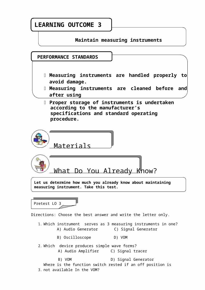
Dashed Lines
Dashed lines (------) are used on schematic and other types of diagrams to show a mechanical linkage between components or parts of components (Fig. 3-6).
Fig. 3-6. Dashed lines are used to indicate the mechanical linkage of a 2-pole, 3-position selector switch.
CONSUMER ELECTRONICS SERVICING 87K to 12 – Technology and Livelihood Education
How Much Have You Learned?Self-Check 3.1
DIRECTIONS: Write the letter of the best answer on the space provided for before each number.
______ 1. A letter designation is written near or beside a symbol to indicate what type of component that symbol is. The letter designation for transistor is _______.
A. Q C. S
B. R D. T
______ 2. These types of lines are used to show mechanical linkages between
components or parts of components on schematic diagram.
A. Connecting lines C. Medium lines
B. Dashed lines D. Thin lines
______ 3. This punctuation mark is used to show the destination of grouped
interrupted lines in a diagram.
A. Bracket C. Open and close quotations
B. Comma D. Question mark
______ 4. To avoid crowding of any necessary notes or reference information,
enough blank space should be left in the areas near, which of the following elements
on a schematic diagram should be considered?
A. Component labels C. Dashed lines
B. Connecting lines D. Symbols
_______5. In a schematic diagram, values of resistors are usually labeled in this unit otherwise noted by the manufacturer.
A. KΩ C. Ohms
B. MΩ D. Resistance
Refer to the Answer Key. What is your score?
CONSUMER ELECTRONICS SERVICING 88K to 12 – Technology and Livelihood Education
How Do You Apply What You Have Learned?Show that you learned something by doing this activity.
Operation Sheet 3.1
I. Directions: Using your electronic template, redraw the schematic diagram of a six-input mixer shown below. Label all components using the values listed as parts list. Be sure to follow the rules in drawing symbols.
Schematic diagram of a six-input audio mixer filter.
Parts list:
R1 – R6 = 22KΩ R16 = 68Ω
R7 – R12 = 39K Ω R17 = 1KΩ
R13 = 100K Ω C1 – C6 = 10µF/16V
R14 = 2.2KΩ C7 – C8 = 47µF/16V
R15 = 6.8KΩ Q1 = 2SC945
CONSUMER ELECTRONICS SERVICING 89K to 12 – Technology and Livelihood Education

II. Redraw the diagram of a 30-watt audio amplifier shown below applying the standard drafting practices. Label all components of the 30-watt audio amplifier using the values listed in the parts list.
Schematic diagram of a 30-watt audio amplifier.
CONSUMER ELECTRONICS SERVICING 90K to 12 – Technology and Livelihood Education
III. DIRECTIONS: Shown in Fig. 3-7A is a schematic diagram of a 50-watt booster amplifier and in Fig. 3-7B is its pictorial diagram. Redraw the pictorial diagram and write in Table 3-3 the name of components/devices indicated by arrows and give their functions.
Fig. 3-7A. Schematic diagram of a 50-watt booster amplifier.
Fig. 3-7B. Pictorial diagram of a 50-watt booster amplifier.
CONSUMER ELECTRONICS SERVICING 91K to 12 – Technology and Livelihood Education

Table 3-3. Name of components, devices and their functions.
Name of component/device Function in the circuit
1.
2.
3.
4.
5.
6.
7.
8.
IV. DIRECTIONS: Redraw the diagram of a discrete audio amplifier of a typical AM
radio receiver shown below which is NOT properly drawn. Be sure to make your
diagram more presentable by following the Standard Drafting Practices.
C18
CONSUMER ELECTRONICS SERVICING 92K to 12 – Technology and Livelihood Education
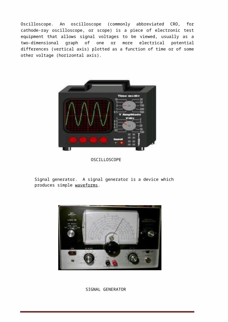
How Well Did You Perform?
Find out by accomplishing the Scoring Rubric honestly and sincerely. Remember it is your learning at stake!
ASSESSMENT PLANDirections: Put a check on designated box if you observed the following criteria.
Get from assessment criteria of the module (CBC) YES NO
Electronic components are specified according to their jobs.
Electronic components are identified based on their functions.
Electronic components which do not conform to the quality standard are identified and marked for disposal.
Electronic diagrams are identified according to job requirements.
The equivalent components of the electronic symbols are identified.
The connection of the electronic symbols in a circuit is identified
The symbols used are appropriate to the electronic components.
Electronic diagrams are drawn based on the requirements of the job.
The diagrams drawn provide all the specifications required by the job identified.
Prepared by: Date:
Checked by: Date:
CONSUMER ELECTRONICS SERVICING 93K to 12 – Technology and Livelihood Education

Observation Checklist
Students name:Teachers name:Name of School
Competency standards
Unit of competency:Instructions for the teacher:1. Observe the student [insert description of activity being observed]. 2. Describe the assessment activity and the date in which it was undertaken. 3. Place a tick in the box to show that the student completed each aspect of the activity in
accordance with the standard expected in the enterprise. 4. Complete the feedback sections of the form. Date of observation
Description of assessment activityLocation of assessment activityThe Student…… If yes, tick the box
Did the student overall performance meet the standard? Yes No
Feedback to student
Teachers signature: Date:
CONSUMER ELECTRONICS SERVICING 94K to 12 – Technology and Livelihood Education
Observation and Questioning Checklist
Student’s name:Teacher’s name:Assessment Center
Competency standards
Unit of competency:Instructions for the teacher:1. Observe the student [insert description of activity being observed]. 2. Describe the assessment activity and the date on which it was undertaken. 3. Place a tick in the box to show that the student completed each aspect of the activity in
accordance with the standard expected in the enterprise. 4. Ask the student a selection of the questions from the attached list to confirm his/her
underpinning knowledge. 5. Place a tick in the box to show that the student answered the questions correctly. 6. Complete the feedback sections of the form. Date of observation
Description of assessment activity
Location of assessment activityThe student…. If yes, tick the box can
Did the student’s overall performance meet the standard? Yes No
CONSUMER ELECTRONICS SERVICING 95K to 12 – Technology and Livelihood Education

Demonstration
Students name:
Teacher’s name:
Unit of competency:
Competency standards:
Date of assessment:
Time of assessment:
Instructions for demonstrationGiven the necessary materials the trainee/student must be able to:
Materials and equipment:
to show if evidence is
demonstrated
During the demonstration of skills, did the Yes No N/Astudent:
The student’s demonstration was:
Satisfactory
Not Satisfactory
CONSUMER ELECTRONICS SERVICING 96K to 12 – Technology and Livelihood Education
PERFORMANCE TEST
Student Name Date
Competency: Test Attempt
1st2nd3rd
Directions:
CALL TEACHER and ask him/her to assess your performance in the following critical task and performance criteria below
You will be rated based on the overall evaluation on the right side.
OVERALL EVALUATION
Level
AchievedPERFORMANCE LEVELS
4 - Can perform this skill without supervision and with initiative and adaptability to problem situations.
3 - Can perform this skill satisfactorily without assistance or supervision.
2 - Can perform this skill satisfactorily but requires some assistance and/or supervision.
1 - Can perform parts of this skill satisfactorily, but requires considerable assistance and/or supervision.
Teacher will initial level achieved.
CONSUMER ELECTRONICS SERVICING 97

K to 12 – Technology and Livelihood Education
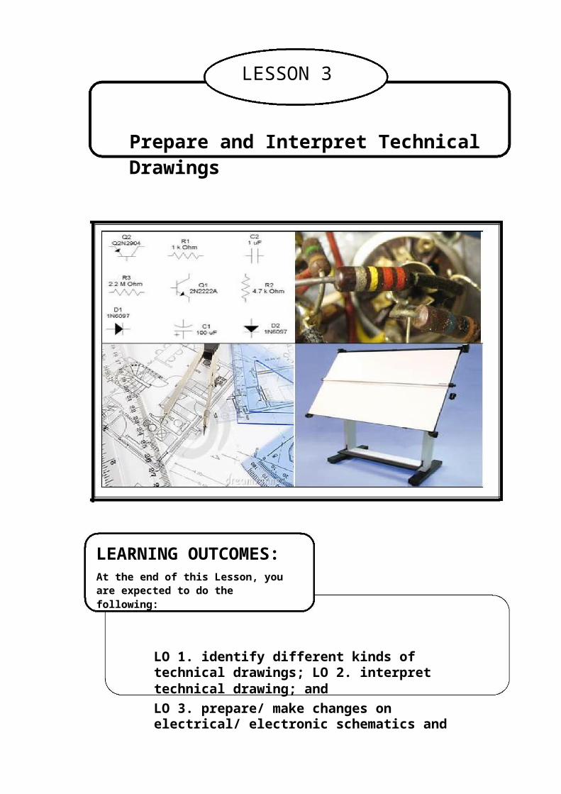
PERFORMANCE STANDARDS
For acceptable achievement, all items should receive a "Yes" or Yes NoN/A"N/A" response.
Get from Performance criteria of the module (TR)
CONSUMER ELECTRONICS SERVICING 98K to 12 – Technology and Livelihood Education

Written report
Student’s name:Teacher’s name:Assessment Center
Competency standards
Unit of competency:Task:Your task is to: [insert description of task]
Submission date:
Use the checklist below as a basis for judging whether the student’s report meets the required competency standards.The student’s report…. If yes, tick the box can solve quantities needed through percentage can tabulate data correctly can convert temperature to the required temperature scale
can fill in appropriate form completely and correctly
can identify proper method of sealing packed products can label correctly packed products Overall did the student’s report meet the standard? Yes No
Comments:
Student’s Date:signature:Teacher’s Date:signature:
CONSUMER ELECTRONICS SERVICING 99K to 12 – Technology and Livelihood Education
Congratulations! You did a great job! Rest and relax a while then move on to the next lesson. Good luck!
REFERENCES
Enriquez, Marcelo T. Electronics Technology IV; Souvenir Publications, Inc.: 2003
L Tan, Michael Q., Gantalao, Fred T., Lasala, Rommel M. Simple Electronics; Andes Mountain Printers: 2004
CONSUMER ELECTRONICS SERVICING 100K to 12 – Technology and Livelihood Education
LESSON 4
Practice Occupational Health and Safety
LEARNING OUTCOMES:At the end of this Lesson, you are expected to do the following:
LO 1. identify health hazards and occupational risks; and
LO 2. observe occupational and safety practices.
CONSUMER ELECTRONICS SERVICING 101
K to 12 – Technology and Livelihood Education

Definition of TermsElectronics Laboratory - a place where activities pertaining to electronics projects are done
Electric shock - a sudden discharge of electricity
Electrostatic discharge - releasing of the electrical charges produced by the human body to ground
Gloves - covering of leather, cotton, silk, etc for the hand usually with separated fingers.
Goggle - spectacles for protecting eyes from glare, dust, and other pollutants.
Hazard - something causing danger
Mask - covering for concealing the face
Maintenance - keeping up with an A1 operation
Occupational health - pertaining to wellness of an individual with reference to an activity or job in any of the workplace identified
Personal Protective Equipment - (PPE) equipment used to protect one’s body from hazards and danger of the electronics trades
Risk - exposure to something unpleasant
Safety practices - set of rules or procedures intended for a safe execution of a certain activity or job in a laboratory
5S - five actions that start with letter S that helps in the arrangement of things in a laboratory Systematize. Sort, Sweep, Self discipline, Sanitize
Systematize – to arrange methodically things in a laboratory
Standardize - to make things in same features or level in quality or achievement
Sort - arrange things according to kinds, types, or classification
Injury - damage or harm to the structure or function of the body caused by an outside agent or force, which may be physical or chemical
Cuts - break in the skin inflicted by sharp objects
Burns - damage in the skin caused by exposure to fire or excessive heat
Fire extinguisher - an equipment of chemicals intended to terminate or extinguish fire
First Aid Kit – a kit containing medicine for initial treatment of any wounds inflicted to a person
CONSUMER ELECTRONICS SERVICING 102K to 12 – Technology and Livelihood Education
LEARNING OUTCOME 1
Identify health hazards and occupational risks
PERFORMANCE STANDARDS
Health hazards and occupational risks are identified. Safety nets are formulated and installed. Protective equipment are identified. Occupational health and safety practices are observed
What Do You Already Know?Let us determine how much you already know about identifying health hazards and occupational risks. Take this test.
Pretest LO 1
Directions: Choose the best answer. Write letters only.
1. What is the equipment that is used to discharge electrical charges produced by thehuman body?
A.) Audio Generator C) ESDB) Signal Generator D) VOM
2. What is the term for an exposure to unpleasant situation?A) Chance C) DangerB) Opportunity D) Risk
3. What are the set of rules or practices intended for a safe execution of work?A) Safety practices C) Policy orderB) Rules and regulations D) Action plan
4. What tools are not recommended to be used in electronics work?A) Brand new tools C) Damaged toolsB) Branded tools D) Standard tools
5. What is the best place for electronic hand tools and equipment?A) Tool box C) Tool roomB) Tool cabinet D) Tool bag
CONSUMER ELECTRONICS SERVICING 103K to 12 – Technology and Livelihood Education

What Do You Need To Know?Read Information Sheet 1.1 very well then find out how much you can remember and how much you learned by doing Self-check 1.1.
Information Sheet 1.1
In every field of work, there are safety precautions and practices to be followed to prevent accidents. Sometimes before an accident occurs a warning is given, so the individual concerned can prepare for the undesirable eventualities. In some situations, no warning at all is served and anyone is caught by surprise.
In areas where students are acquiring basic technical skills safety begins the moment they enter the work area or even before reaching that work area. Identifying health hazards and occupational risks is indispensable. In laboratory areas where students stay to acquire skills there are certain points to consider.
1. Electrical hazards. Electrical hazards are the type of risks that are more likely fatal than any other hazards that can happen in a laboratory room. Electrical hazards such as electrical shocks from open wires, grounded electrical appliances can be found anywhere in a disorganized laboratory area.
CONSUMER ELECTRONICS SERVICING 104K to 12 – Technology and Livelihood Education
2. Hazards from improper use of hand tools. Hand tools are classified into cutting
tools, driving tools, boring tools, joining tools, and measuring tools.
Cutting tools may inflict injuries when improperly handled due to their sharp edges that can cut through the skin of the human body.
Cutter knife hacksaw scraper
Driving tools
Driving tools like screw drivers and hammers, when used improperly can break human flesh or fracture bones which are very painful to an individual.
Claw hammer
Screwdrivers
CONSUMER ELECTRONICS SERVICING 105K to 12 – Technology and Livelihood Education

Boring tools
Drill bits, Center punch, and reamer are boring tools. These tools also do damage when not properly used.
Electric drill Drill bits with handle
Soldering tools
Soldering tools such as soldering iron, soldering gun, and hot air soldering cause extreme heat and can burn the skin when improperly used.
Soldering gunSoldering iron
Other hazards and risks can be caused by objects not properly placed in laboratory area where crumbling or falling is highly possible.
CONSUMER ELECTRONICS SERVICING 106K to 12 – Technology and Livelihood Education
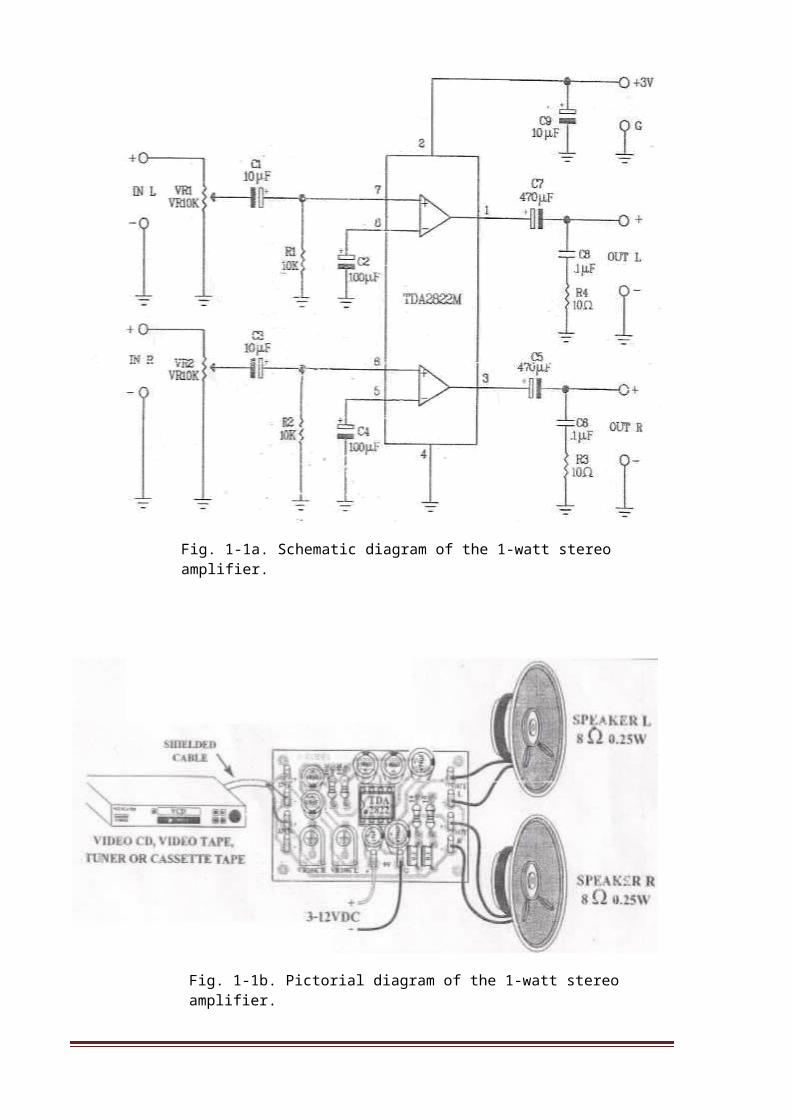
Objects placed on top of a cabinet can be very dangerous to students and teachers as well. Other untoward incidents can also happen as a result of haste and sometimes neglect of
tools, materials, and equipment in the shop. Disorderliness can also make things worse, hence presence of mind, particularly while working is important. It is very useful to
follow guidelines that will serve as a safety net.
TOOLS MAINTENANCE and SAFETY RULES
Tools will last longer when properly kept and maintained. A good worker keeps and cares for his tools. The following are some pointers to follow in keeping hand tools in good condition.
1. Be sure to inspect tools before using them. This is to check if they are in good working condition. The evidence is when you are able to use them smoothly and conveniently with ease and comfort.
2. After using a tool, clean it thoroughly with a damp cloth before keeping it in a tool box or cabinet.
3. Oil the metal parts of a tool to prevent any form of damage caused by air, water, or rust.
CONSUMER ELECTRONICS SERVICING 107K to 12 – Technology and Livelihood Education

The following safety rules should be understood and strictly followed to avoid accidents while working.
1. Avoid wearing loose clothing when working. Sleeves should be fit and shirts tucked in as much as possible. Remove ties, watches, rings, and other jewelry from your body.
2. Report immediately injuries or accidents of any type to your teacher.
3. Never put fasteners or any small metal articles in or near your mouth when working.
4. Never throw tools of any type around. Make sure the sharp edge of cutting tools are away from the edge of the table or work bench.
5. Keep working areas clean and free from disposable materials.
6. Secure the help of your classmates when carrying heavy tools to avoid accidents.
7. Never use dull or damaged tools.
8. Do not use tools with loose handles and ragged. Report cases like these to the teacher and do the necessary repair and adjustments, if possible.
9. Know and observe safety measures specific for each tool or operation.
Safety Requirements
For your protection, observe the following safety requirements:
Follow all cautions, warnings, and instructions marked on the equipment.
Ensure that the voltage and frequency rating of the power outlet matches the electrical rating labels on the system.
Use properly grounded power outlets.
Safety Requirements with the Use of Personal Protective Equipment
CONSUMER ELECTRONICS SERVICING 108K to 12 – Technology and Livelihood Education
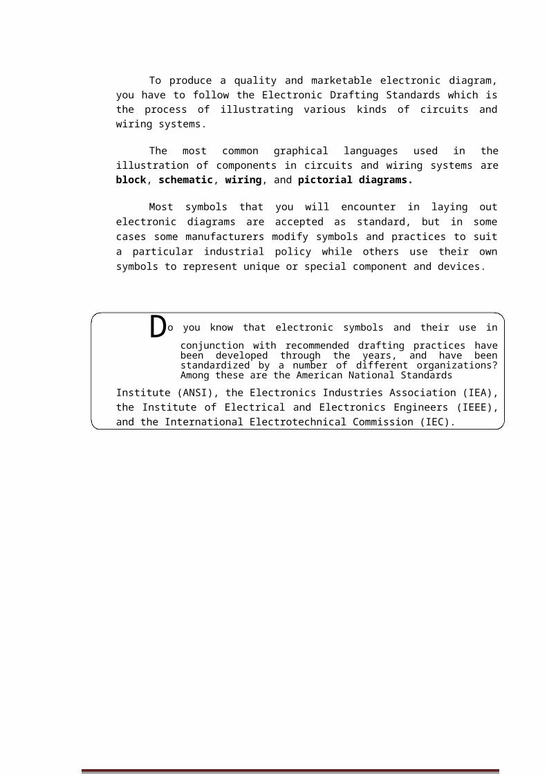
Hand Tool Design, Selection, and Setup
1. Weight - Use the lightest weight tool possible to avoid injury. Excessively heavy tools must be equipped with mechanical support and attached hoses should be supported.
Support - Equip tools with some means of mechanical support so you don't need to hold a heavy tool continuously while working. If mechanical support cannot be provided, the workstation should be designed so you can put the tool down or rest it in a holster when it is not in use.
2. Balance - Additional force is required to use an unbalanced tool. The tool's center of gravity should be close to the body, close to the handles, and in line with the center of the hand holding the tool.
CONSUMER ELECTRONICS SERVICING 109K to 12 – Technology and Livelihood Education

3. Torque Control - High torque requires a lot of force to keep the tool from rotating out of your hand. Torque settings should be set to the minimum required by job specifications, especially for in-line and pistol-shaped tools.
4. Grip - Tool handles should allow stable and efficient grip. The handle should be cylindrical or oval in shape, with a diameter of between 1.25 and 1.75 inches. Tool handles should contact as much of the hand and fingers as possible. Grips should be made of non-slip compressible and non-conductive material. Avoid form-fitting handles (handles with finger grooves), since they may not fit the hand size of every user. Handles should be kept clean and free from slippery grease, oil, or sweat.
CONSUMER ELECTRONICS SERVICING 110K to 12 – Technology and Livelihood Education
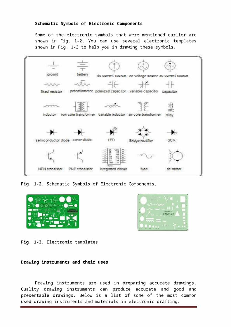
5. Span - On two-handled manual tools, like pliers, the open span should be about 4 inches and the closed span should only be about 1.5 inches.
6. Spring-loaded handles - A spring-loaded mechanism saves muscular effort and reduces mechanical stress on the backs and sides of fingers for such tools as scissors, pliers, and other manual cutting and gripping tools which have to be opened and closed repeatedly during use.
7. Choose the right tool shape - Pistol-shaped tools should be used on a vertical surface or on a horizontal surface below waist height. Bend the tool, not the wrist.
8. Avoid bending over your work.
CONSUMER ELECTRONICS SERVICING 111K to 12 – Technology and Livelihood Education

9. Avoid overhead work if possible. Use a ladder to reduce the need for outstretched arms.
10. Keep the elbows close to the body.
11. Tilt the work surface instead of the wrist.
CONSUMER ELECTRONICS SERVICING 112K to 12 – Technology and Livelihood Education
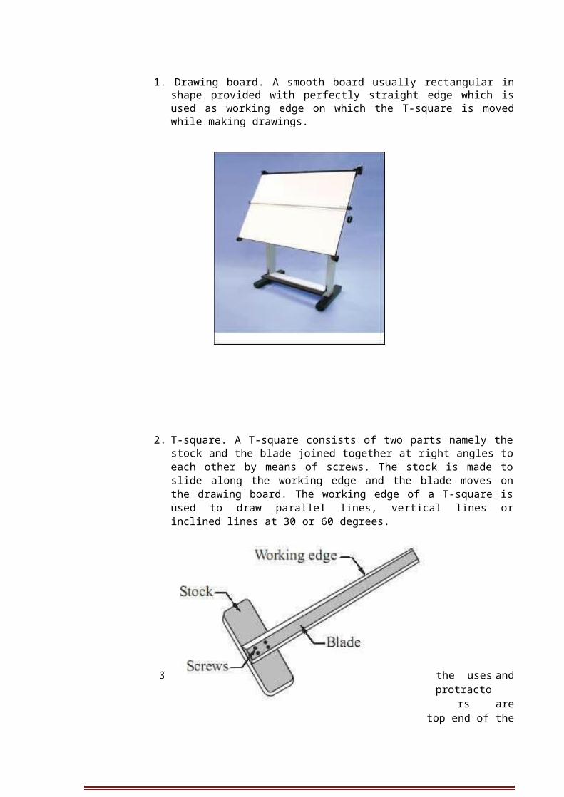
12. Stand with weight evenly distributed on both feet. When standing for long periods of time, rest one foot on a sturdy object above floor height and switch legs periodically.
13. Sit up straight so the chair offers good back support. Adjust the chair back so it comfortably supports the natural curve of the lower back. Adjust the seat height to allow thighs to be parallel to the floor.
CONSUMER ELECTRONICS SERVICING 113K to 12 – Technology and Livelihood Education

How Much Have You Learned?
Self-Check 1.1
Directions: Write the safety requirement indicated in each number on a separate sheet of paper
1. 2.
3. 4. 5.
CONSUMER ELECTRONICS SERVICING 114K to 12 – Technology and Livelihood Education
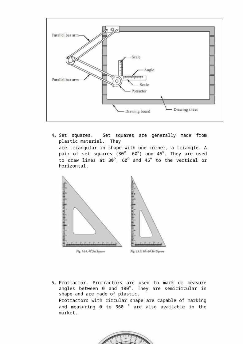
How Do You Apply What You Have Learned?Show that you learned something by doing this activity
Operation Sheet 1.1
Safety Requirements with the Use of Personal Protective Equipment
Instruction:
1. Without looking at Information Sheet 1.1, answer the written test on the safety requirements in using hand tools and test equipment in Self-Check 1.1.
2. After finishing your test, you can compare your answer with Answer Key 1.1.
3. You must get a score of 7 - 9 to get a grade of Very Good and pass the self-check based on Assessment Criteria 1.1.
Operation Sheet 1.2
Objective: To arrange tools and equipment in a tool cabinet according to the tools’ classification.
Materials, Tools and Equipment:
Assorted basic electronic hand tools and equipment Tool cabinet Paper Marking pen
Procedure:
1. Make a list of electronic hand tools and equipment. 2. Sort electronic hand tools according to their function. 3. Place electronic hand tools in separate areas in the cabinet according to their
function. a. Soldering tools b. Cutting tools c. Boring tools d. Bending tools e. Measuring tools
4. Label the areas according to functions of tools. 5. Locate tools that are defective. 6. Make an inventory of the tools and equipment according to function and label
the status of the tools and equipment.
CONSUMER ELECTRONICS SERVICING 115K to 12 – Technology and Livelihood Education

Operation Sheet 1.3
Objective: To evaluate an electronics room as to the status of health hazards and occupational risks.
Materials, Tools, and Equipment:
1. Electronics Room 2. Laboratory tables with electrical wiring 3. Tool cabinet/ Tool room
Instructions:
1. Evaluate an electronics room as to the following: Health hazards in the laboratory tables Health hazards in the tool room/tool cabinet Occupational risks when using electronics equipment
How Well Did You Perform?Find out by accomplishing the Scoring Rubric honestly and sincerely. Remember it is your learning at stake!
Assessment Criteria 1.1
Score Descriptive Grade
5 Excellent
4 Very good
3 Good
1-2 Fair
0 Poor
CONSUMER ELECTRONICS SERVICING 116K to 12 – Technology and Livelihood Education
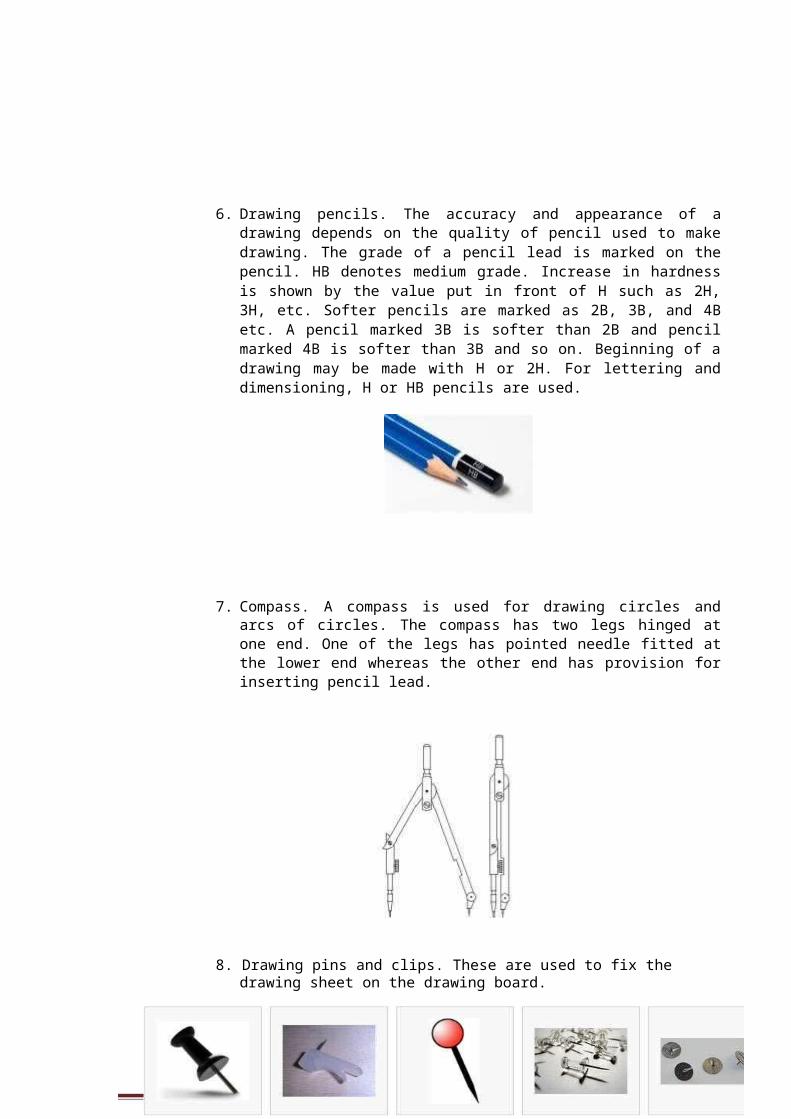
PERFORMANCE TEST
Learner's Name Date
Competency: Test Attempt
1st 2nd 3rd
Directions: OVERALL EVALUATION
Level
CALL TEACHER and ask Achieved PERFORMANCE LEVELShim/her to assess yourperformance in the following 4 - Perform this skill without supervision and withcritical task and performance initiative and adaptability to problem situations.criteria below
3 - Perform this skill satisfactorily withoutassistance or supervision.
You will be rated based on the 2 - Perform this skill satisfactorily but requiresoverall evaluation on the right some assistance and/or supervision.side.
1 - Perform parts of this skill satisfactorily, butrequires considerable assistance and/orsupervision.
Teacher will initial the level achieved.
PERFORMANCE STANDARDS
For acceptable achievement, all items should receive a "Yes" or Yes No N/A"N/A" response.
1. Identify health hazards and occupational risks in the workingplace.
2. Identify health hazards and occupational risks in thearrangement of tools and equipment.
3. Identify health hazards and occupational risks in the manner ofhandling tools and equipment.
4. Identify health hazards and occupational risks inlaboratory’s electrical wiring system.
5. Identify health hazards and occupational risks in thestructure of the laboratory room.
CONSUMER ELECTRONICS SERVICING 117K to 12 – Technology and Livelihood Education

How Do You Extend Your Learning?
Objective: To reinforce the knowledge and skills acquired in the information sheet, job sheet, and operation sheet.
1. Prepare a tools and equipment maintenance chart. Inspect all tools and equipment found in your shop room.
2. Indicate which ones need cleaning, repairing, rearranging, and labeling.
3. Determine what safety devices are found in your shop.
4. Identify health hazards and occupational risks found in your shop room.
CONSUMER ELECTRONICS SERVICING 118K to 12 – Technology and Livelihood Education
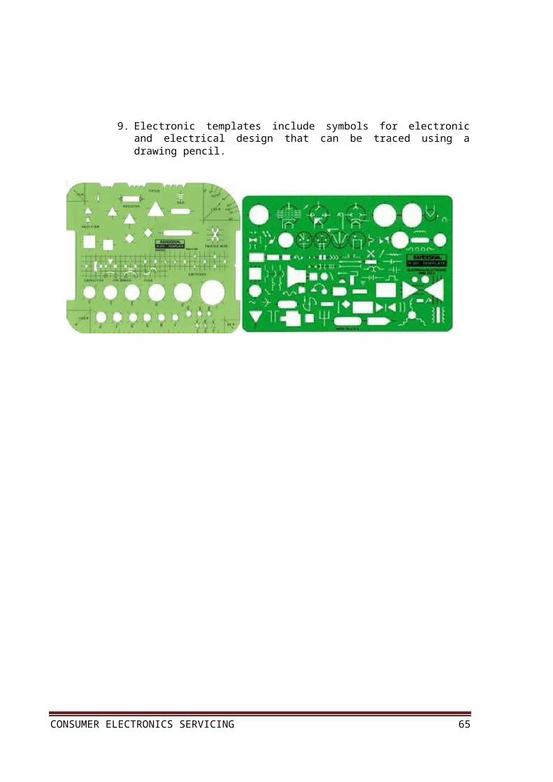
LEARNING OUTCOME 2
Observe occupational health and safety practices
PERFORMANCE STANDARDS
Measure advancing occupational health are observed. Safety Procedures are practiced.
What Do You Already Know?Let us determine how much you already know about observing occupational health and safety practices. Take this test.
Pretest LO 2
Directions: Modified true or false. Write true if the statement is true. If it is not true, write the word or words that make the statement false.
1. As a general rule, all passages must be free of any obstruction that will hamper the movement of persons in the area.
2. Treat every wire in the electrical system as live wire and act accordingly. Always attempt to work in any “live” electronic or electrical circuits.
3. Never use tools or equipment you are not familiar with or you do not know how to operate. Always ask assistance from your teacher to avoid accidents.
4. The shop is a place of work so one can engage in a play while at work.
5. Keep the work area always clean and orderly.
CONSUMER ELECTRONICS SERVICING 119K to 12 – Technology and Livelihood Education

What Do You Need To Know?
Read Information Sheet 2.1 very well then find out how much you can remember and how much you have learned by doing Self-check 2.1.
Information Sheet 2.1
In the process of observing occupational health and safety practices, measures must be set to be followed by the students. Particularly, an electronics lab has these measures to highlight the manner of observing safety practices.
1. As a general rule all passages must be free of any obstruction that will hamper the movement of persons in the area. This provision also provides safety during emergency situations like fire and earthquake.
2. Treat every wire in the electrical system as live wire and act accordingly. Never attempt to work in any “live” electronic or electrical circuits.
3. All tools and equipment must be checked to be in A1 condition before they are lent to users.
4. All instructions must be centralized and must emanate from the person-in-charge.
5. The shop is a place of work, so do not engage in a play while at work.
6. Never use tools or equipment you are not familiar with or you do not know how to operate. Always ask assistance from your teacher to avoid accidents.
7. Keep hand tools such as screw driver, files, and pliers on the table or tool cabinet and not in your pocket as it might hurt you or other people.
8. Use only tools that are in good condition.
9. Report accidents and injuries to your teacher no matter how minor.
10. Keep the work area always clean and orderly.
CONSUMER ELECTRONICS SERVICING 120K to 12 – Technology and Livelihood Education
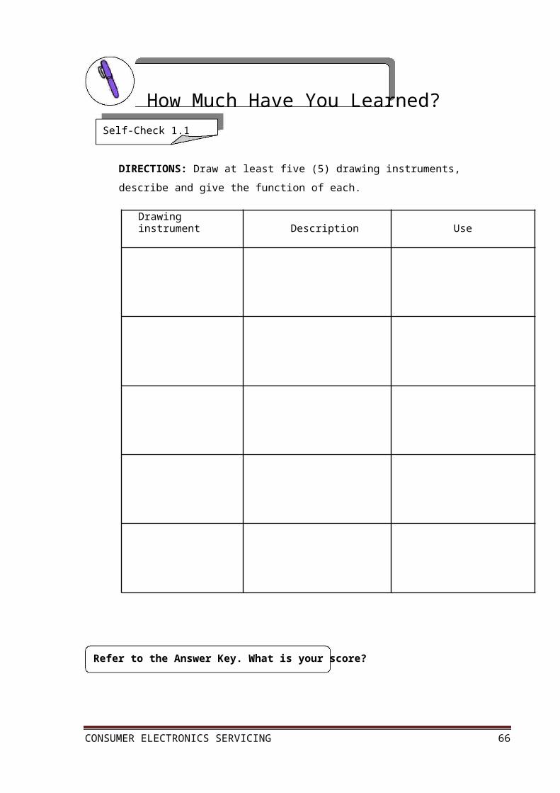
In every field of life whether in school, industries, and elsewhere, the observance of safety is a must. There are basic safety guidelines to prevent minor injuries such as cuts, burns, electrical shock and damage to eyesight as well as the loss of human lives. As a good practice, make sure that a fire extinguisher and a first aid kit are available in case of injury or even fire.
Personal Safety Guidelines
These are general guidelines for all types of troubleshooting, installation and maintenance tasks. Take them seriously. They may keep you out of a dangerous situation.
1. Never work alone in any electronics project. Always have someone to keep an eye out for any potential problem.
2. Always use protective eyewear or safety goggles when appropriate.
3. Do not go barefoot when moving tool boxes or laboratory equipment.
4. Never assume that an electrical device is safe to handle. Perform your test with the device disconnected from the power source.
5. Some tests must be connected with power applied. Be extremely cautious when performing these tests.
6. Do not wear jewelry of any kind while performing works in the laboratory.
CONSUMER ELECTRONICS SERVICING 121K to 12 – Technology and Livelihood Education

How Much Have You Learned?Self-Check 2.1
Directions: Modified TRUE or FALSE. Write true if the statement is true. If it is not true, write the word or words that make the statement false.
1. As a general rule, all passages must be free of any obstruction that will hamper the movement of persons in the area.
2. Treat every wire in the electrical system as live wire and act accordingly. Always attempt to work in any “live” electronic or electrical circuits.
3. Never use tools or equipment you are not familiar with or you do not know how to operate. Always ask assistance from your teacher to avoid accidents.
4. The shop is a place of work so one can engage in a play while at work. 5. Keep the work area always clean and orderly.
Refer to the Answer Key. What is your score?
CONSUMER ELECTRONICS SERVICING 122K to 12 – Technology and Livelihood Education
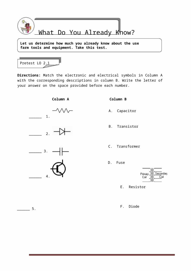
How Do You Apply What You Have Learned?
Show that you have learned something by doing this activity.
Operation Sheet 2.1
Materials, Tools and Equipment:
Electronic componentsElectric wiresBasic hand toolsMeasuring equipmentWorking tablesChairs and other lab facilities
Procedure:
1. Arrange electronic components based on safety considerations.
2. Arrange the basic hand tools together in a tool cabinet as to facilitate the measures regarding tools for occupational health and safety practices.
3. Arrange electrical wires according to standard safety measures.
4. Arrange electronic equipment considering occupational health and safety standards.
5. Arrange lab tables, chairs, and other related facilities in line with standard occupational health and safety practices.
6. Prepare an occupational health and safety practices report according to the result of the operation made.
Operation Sheet 2.2
Materials, Tools, and Equipment:
Meter for measurement
Drawing papers
A laboratory room
Laboratory tables, chairs
Tool cabinet
CONSUMER ELECTRONICS SERVICING 123K to 12 – Technology and Livelihood Education

Instructions:
Using a meter, measure the dimension of the laboratory room and other facilities and make a layout of your room. Review the set occupational health and safety practices and relate it to the existing shop layout.
Using your observation and analyses, draw a proposed layout of your shop room showing the flow of shop activities focusing on occupational health and safety practices.
How Well Did You Perform?
Find out by accomplishing the Scoring Rubric honestly and sincerely. Remember it is your learning at stake!
PERFORMANCE TEST
Learner's Name Date
Competency: Test Attempt
1st 2nd 3rdOVERALL EVALUATION
Directions: Level
Achieved PERFORMANCE LEVELSCALL TEACHER, ask him/her
4 - Perform this skill without supervision and withto assess your performance ininitiative and adaptability to problem situations.the following critical task and
performance criteria below 3 - Perform this skill satisfactorily withoutassistance or supervision.
You will be rated based on the 2 - Perform this skill satisfactorily but requires
overall evaluation on the right some assistance and/or supervision.side.
1 - Perform parts of this skill satisfactorily, butrequires considerable assistance and/orsupervision.
Teacher will initial the level achieved.
CONSUMER ELECTRONICS SERVICING 124K to 12 – Technology and Livelihood Education
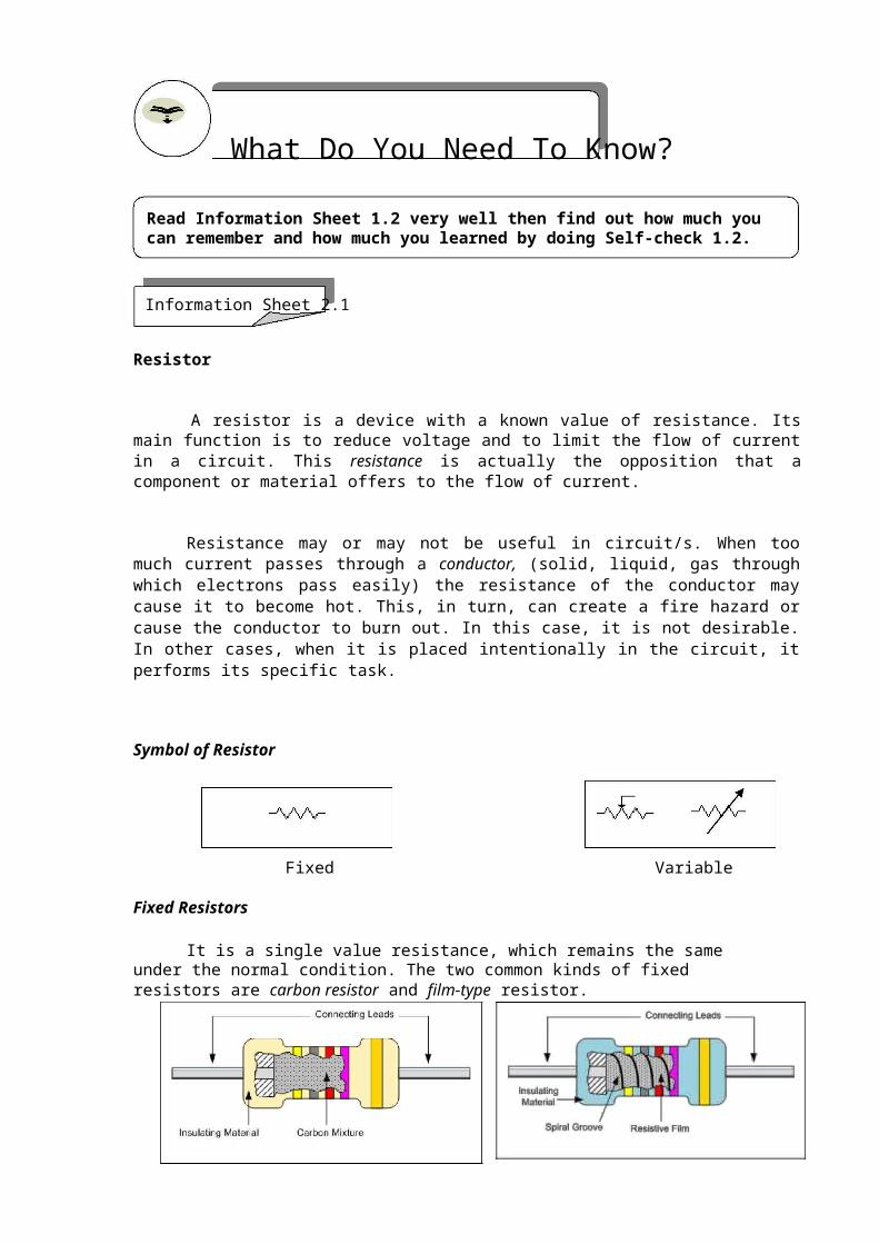
PERFORMANCE STANDARDS
For acceptable achievement, all items should receive a "Yes" or Yes No N/A "N/A" response.
1. Perform occupational health and safety practices with respect to the movement in the laboratory.
2. Perform occupational health and safety practices in the arrangement of basic hand tools and equipment.
3. Perform occupational health and safety practices in the
arrangement of wires in the laboratory area.
4. Manifest danger in the arrangement of facilities in the laboratory area.
5. Suggest laboratory set-up based on the standard occupational health and safety practices.
Congratulations! You did a great job! Rest and relax a while then move on to the next lesson. Good luck!
REFERENCES
Enriquez, Marcelo T., Electronics Technology IV; Souvenir Publications, Inc. 2003
Grob, Bernard, Basic Electronics, 4th Edition; New York: McGraw-Hill Company, USA: 1982
Tan, Michael Q.; Gantalao, Fred T.; Lasala, Rommel M. Simple Electronics; Andes Mountain Printers; 2004
CONSUMER ELECTRONICS SERVICING 125K to 12 – Technology and Livelihood Education

LESSON 5
Maintain Tools and Equipment
LEARNING OUTCOMES:At the end of this Lesson, you are expected to do the following:
LO 1. maintain hand tools and equipment; andLO 2. perform basic preventive maintenance of electronic tools and equipment.
CONSUMER ELECTRONICS SERVICING 126
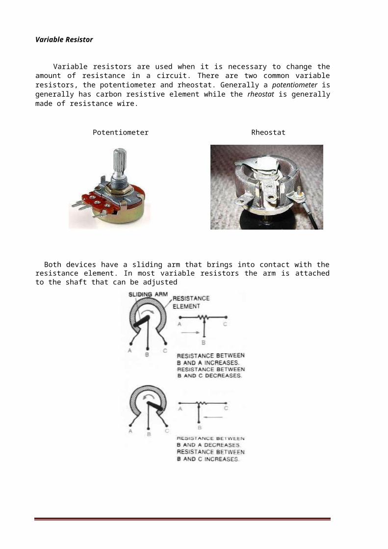
K to 12 – Technology and Livelihood Education