construction soil and water management sub- plan resource centre... · aecom teralba sustainable...
TRANSCRIPT
AECOM Teralba Sustainable Resource Centre
13 January 2012
C
Appendix C
Construction Soil and Water Management Sub-Plan

Teralba Sustainable Resource Centre CiviLake 13 January 2012
Soil and Water Management Plan Teralba Sustainable Resource Centre
AECOM Teralba Sustainable Resource Centre Soil and Water Management Plan
13 January 2012
Soil and Water Management Plan Teralba Sustainable Resource Centre
Prepared for
CiviLake
Prepared by AECOM Australia Pty Ltd Level 21, 420 George Street, Sydney NSW 2000, PO Box Q410, QVB Post Office NSW 1230, Australia T +61 2 8934 0000 F +61 2 8934 0001 www.aecom.com ABN 20 093 846 925
13 January 2012
AECOM in Australia and New Zealand is certified to the latest version of ISO9001 and ISO14001.
© AECOM Australia Pty Ltd (AECOM). All rights reserved.
AECOM has prepared this document for the sole use of the Client and for a specific purpose, each as expressly stated in the document. No other party should rely on this document without the prior written consent of AECOM. AECOM undertakes no duty, nor accepts any responsibility, to any third party who may rely upon or use this document. This document has been prepared based on the Client’s description of its requirements and AECOM’s experience, having regard to assumptions that AECOM can reasonably be expected to make in accordance with sound professional principles. AECOM may also have relied upon information provided by the Client and other third parties to prepare this document, some of which may not have been verified. Subject to the above conditions, this document may be transmitted, reproduced or disseminated only in its entirety.
AECOM Teralba Sustainable Resource Centre Soil and Water Management Plan
13 January 2012
Quality Information Document Soil and Water Management Plan
Ref
p:\60101141_lmrc\4. tech work area\cemp\appendices to cemp\appendix c construction soil and water management plan\soil and water management plan - final.doc
Date 13 January 2012
Prepared by Celeste Swan
Reviewed by Andrew Kielniacz
Revision History
Revision Revision Date Details
Authorised
Name/Position Signature
3 12-Oct-2011 Final Joshua Lasky Project Manager
AECOM Teralba Sustainable Resource Centre Soil and Water Management Plan
13 January 2012
Table of Contents 1.0 Introduction 1
1.1 Background 1 1.2 Purpose 1 1.3 Objectives 1
2.0 Site Characteristics 3 3.0 Water Quality Targets 4 4.0 Sediment and Erosion Control Measures 5
4.1 Construction Activities 5 4.2 Management of Activities 5 4.3 Mitigation Measure Requirements 9
4.3.1 Design Requirements 9 4.3.2 Installation and Maintenance Requirements 11
5.0 SWMP Implementation 12 5.1 Overview 12 5.2 Inspection Requirements 14
5.2.1 Pre-Inspection 14 5.2.2 Scope 14 5.2.3 Non-Conformance and Corrective Actions 14
5.3 Roles and Responsibilities 15 Appendix A
Receiving Environment Plan A Appendix B
Erosion and Sediment Control Plan (ESCP) and Typical Details B Appendix C
Control Measure Installation and Maintenance Guidelines C
List of Tables
Table 1 Construction Activities and Management Controls 5 Table 2 Sediment Basin Design Criteria 10 Table 3 Total Sediment basin Volume requirements for 4.7ha site disturbance 11 Table 4 Sediment Basin Volume Requirements Based on disturbed Area of Site 11 Table 5 SWMP Implementation and Operation Requirements 12 Table 6 Roles and Responsibilities 15
AECOM Teralba Sustainable Resource Centre Soil and Water Management Plan
13 January 2012
1
1.0 Introduction
1.1 Background CiviLake is proposing to develop and operate The Teralba Sustainable Resource Centre (referred to as the proposed Facility) on a Site at The Weir Road, Teralba, known as Lots 42, 43, 53 and 54 in Deposited Plan (DP) 16062.
The proposed Facility would be a crushing, grinding and separating operation for construction and green waste materials including concrete, asphalt, recycled asphalt pavement, road base, green waste, bricks, tiles and soil.
The proposed Facility would accept up to 200,000 tonnes per annum (tpa) of construction and green waste material for reuse within CiviLake operations and resale to the construction industry. The project will significantly decrease both the amount of virgin materials Council is required to purchase for its civil works and the volume of construction waste Council disposes to landfill, providing a dual economic and environmental benefit.
The site of the proposed Facility has an area of approximately 7 hectares and is located approximately 2km north of the village of Teralba on a floodplain to the south and west of Cockle Creek. The site will be accessed from a new entry intersection with the Weir Road which adjoins the southern boundary of the site. The site is currently used for light agriculture and is elevated approximately 1m relative to the adjoining land, due to the previous land use of sanitary disposal involving the deposit of biosolids and fill over the site. The site level is proposed to be further raised through filling to cap existing contamination, raise the site above flood levels and facilitate appropriate water management.
The site has been designed in order to enable the practical requirements of the proposed Facility’s operation and to minimise the potential impacts of the proposal on the surrounding environment.
1.2 Purpose The purpose of this Soil and Water Management Plan (SWMP) is to provide a description of the measures to be implemented to mitigate potential soil erosion and resulting water quality impacts on land and water resources within and beyond the areas disturbed during the construction of the Facility. It is a sub-plan of the Construction Environmental Management Plan (CEMP) and assists in ensuring compliance with the DoPI’s Conditions of Approval.
This document details proposed erosion and sediment controls and is intended to document the performance standards and framework for the preparation and implementation of soil and water management controls by CiviLake.
The Conditions of Consent regarding preparation of a Soil and Water Management Plan specifically relate to the operation of the facility.
However the Statement of Commitments included preparation of a Construction Environmental Management Plan that was to include soil and water management measures. :
In addition, Condition 10 of Schedule 4 of DoPI’s Conditions of Approval relevant to the facility during construction require:
10. Except as may be expressly provided in an EPL for the site, the Proponent shall comply with Section 120 of the PEOA Act.
1.3 Objectives The objectives of this SWMP are to:
- Specify relevant erosion and sediment control (ESC) performance criteria and design guidelines;
- Detail the standard ESC controls to be implemented to control soil erosion and water management on site to meet with specified surface water discharge limits
- Document maintenance requirements for the controls
- Establish an inspection framework to ensure proactive management of erosion and sedimentation impacts

AECOM Teralba Sustainable Resource Centre Soil and Water Management Plan
13 January 2012
2
- Outline the reporting and reviewing requirements
- Detail the responsibilities associated with erosion and sedimentation management.
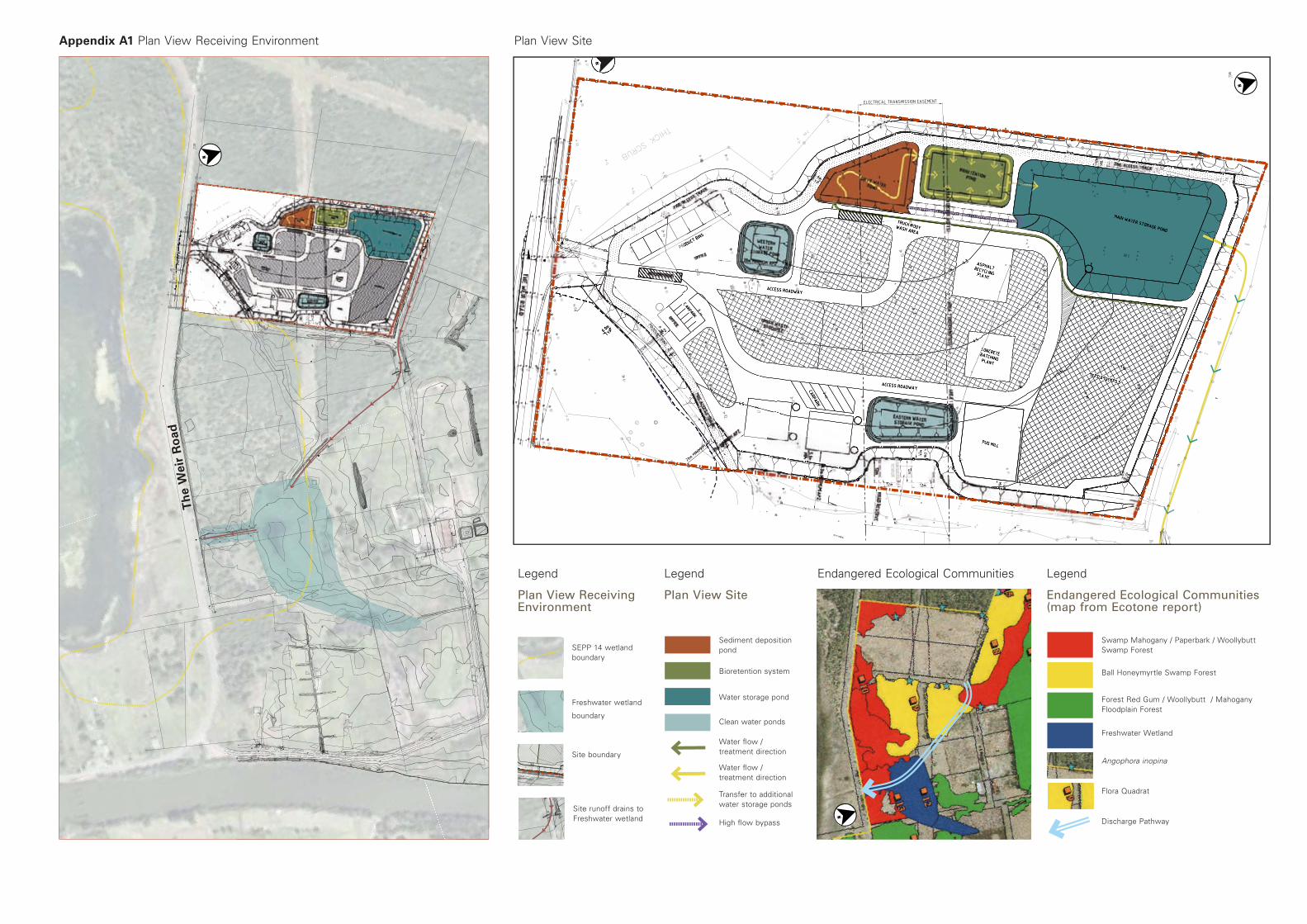
Water discharged from the Teralba Sustainable Resource Centre Project follows an existing drainage pathway (man-made channels) through the downstream swamp forest and freshwater wetland communities and conveys flows into a SEPP14 wetland. The flow pathway is illustrated in Receiving Environment Plan provided in Appendix A. If not managed appropriately, construction activities have the potential to cause environmental harm to these waterways, through offsite transport of pollutants (i.e. sediment, oils and greases, contaminated water).
Therefore, management of construction activities and implementation of ESCs is required to ensure the project maintains a high level of environmental performance and is compliant with the project Conditions of Consent and statutory requirements.
AECOM Teralba Sustainable Resource Centre Soil and Water Management Plan
13 January 2012
3
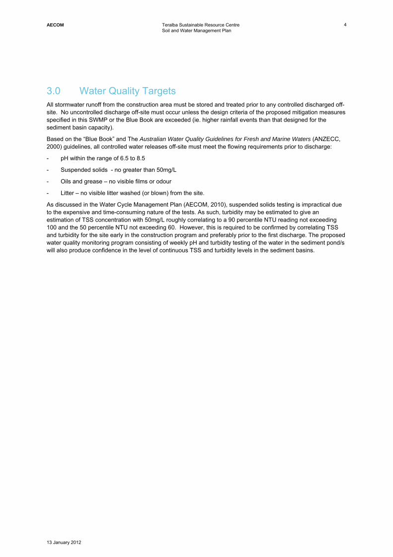
2.0 Site Characteristics The site is located in an alluvial back swamp approximately 200m south of Cockle Creek. The closest point of the creek is approximately 200m from the proposed Facility. A SEPP 14 Wetland exists 200m to the south of the subject site and a number of vegetation communities adjoin the site to the north, west and east. Shallow unlined drainage channels flow east from the site through an existing drainage pathway and eventually into the wetland. The groundwater levels measured at the site range from around 0.5m RL in dry periods and 1.5-1.8m RL measured following high rainfall.
The land is elevated approximately 1m relative to the adjoining land, due to the previous land use of sanitary disposal involving the deposition of biosolids over the site. Fill depths of greater than 2.9 m have been recorded. Locally the site is gently undulating, and the ground surface is hummocky and irregular due to the presence of fill on the site. The ground surface contains troughs approximately 1m in depth. Generally the site slopes at <5° to the south. Surface soils consist of loose sand and clayey sand fill.
AECOM Teralba Sustainable Resource Centre Soil and Water Management Plan
13 January 2012
4
3.0 Water Quality Targets All stormwater runoff from the construction area must be stored and treated prior to any controlled discharged off-site. No uncontrolled discharge off-site must occur unless the design criteria of the proposed mitigation measures specified in this SWMP or the Blue Book are exceeded (ie. higher rainfall events than that designed for the sediment basin capacity).
Based on the “Blue Book” and The Australian Water Quality Guidelines for Fresh and Marine Waters (ANZECC, 2000) guidelines, all controlled water releases off-site must meet the flowing requirements prior to discharge:
- pH within the range of 6.5 to 8.5
- Suspended solids - no greater than 50mg/L
- Oils and grease – no visible films or odour
- Litter – no visible litter washed (or blown) from the site.
As discussed in the Water Cycle Management Plan (AECOM, 2010), suspended solids testing is impractical due to the expensive and time-consuming nature of the tests. As such, turbidity may be estimated to give an estimation of TSS concentration with 50mg/L roughly correlating to a 90 percentile NTU reading not exceeding 100 and the 50 percentile NTU not exceeding 60. However, this is required to be confirmed by correlating TSS and turbidity for the site early in the construction program and preferably prior to the first discharge. The proposed water quality monitoring program consisting of weekly pH and turbidity testing of the water in the sediment pond/s will also produce confidence in the level of continuous TSS and turbidity levels in the sediment basins.
AECOM Teralba Sustainable Resource Centre Soil and Water Management Plan
13 January 2012
5
4.0 Sediment and Erosion Control Measures
4.1 Construction Activities The construction of the Teralba Sustainable Resource Centre will comprise the following civil works activities:
- Site preparation including clearing and any regrading of the site required
- Construction of a perimeter earth bund and pad for the facility using compacted fill materials
- Construction of water storage / treatment ponds
- Construction of stormwater diversion drains
- Construction of a site access intersection and internal roadways
- Utility installations
- Construction of buildings and carpark/hardstand areas
- Erection of perimeter fencing
- Landscaping of embankment batters and channels.
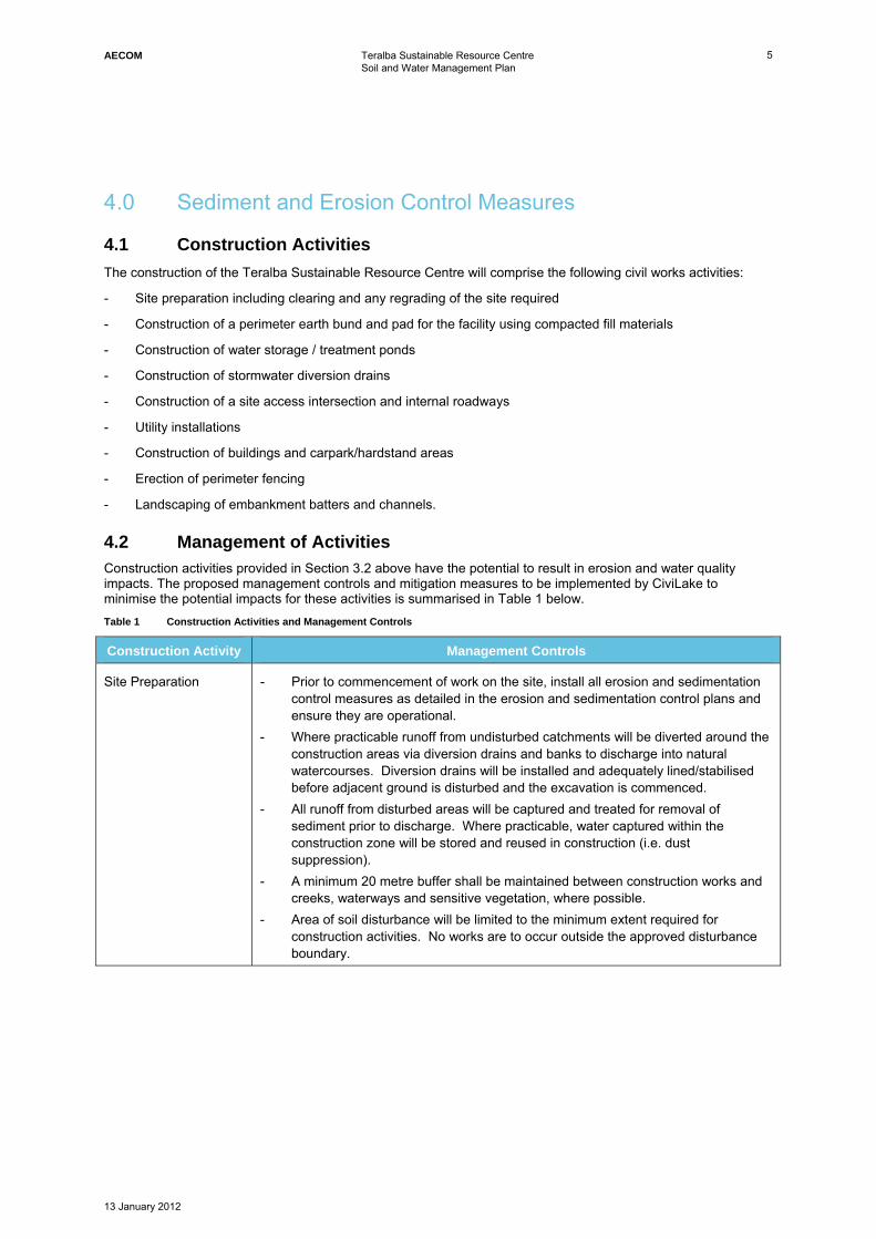
4.2 Management of Activities Construction activities provided in Section 3.2 above have the potential to result in erosion and water quality impacts. The proposed management controls and mitigation measures to be implemented by CiviLake to minimise the potential impacts for these activities is summarised in Table 1 below. Table 1 Construction Activities and Management Controls
Construction Activity Management Controls
Site Preparation - Prior to commencement of work on the site, install all erosion and sedimentation control measures as detailed in the erosion and sedimentation control plans and ensure they are operational.
- Where practicable runoff from undisturbed catchments will be diverted around the construction areas via diversion drains and banks to discharge into natural watercourses. Diversion drains will be installed and adequately lined/stabilised before adjacent ground is disturbed and the excavation is commenced.
- All runoff from disturbed areas will be captured and treated for removal of sediment prior to discharge. Where practicable, water captured within the construction zone will be stored and reused in construction (i.e. dust suppression).
- A minimum 20 metre buffer shall be maintained between construction works and creeks, waterways and sensitive vegetation, where possible.
- Area of soil disturbance will be limited to the minimum extent required for construction activities. No works are to occur outside the approved disturbance boundary.
AECOM Teralba Sustainable Resource Centre Soil and Water Management Plan
13 January 2012
6
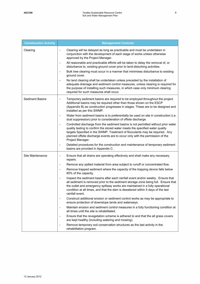
Construction Activity Management Controls
Clearing - Clearing will be delayed as long as practicable and must be undertaken in conjunction with the development of each stage of works unless otherwise approved by the Project Manager.
- All reasonable and practicable efforts will be taken to delay the removal of, or disturbance to, existing ground cover prior to land-disturbing activities.
- Bulk tree clearing must occur in a manner that minimises disturbance to existing ground cover.
- No land clearing shall be undertaken unless preceded by the installation of adequate drainage and sediment control measures, unless clearing is required for the purpose of installing such measures, in which case only minimum clearing required for such measures shall occur.
Sediment Basins - Temporary sediment basins are required to be employed throughout the project. Additional basins may be required other than those shown on the ESCP (Appendix B) as construction progresses in stages. These are to be designed and installed as per this SWMP.
- Water from sediment basins is to preferentially be used on site in construction (i.e. dust suppression) prior to consideration of offsite discharge.
- Controlled discharge from the sediment basins is not permitted without prior water quality testing to confirm the stored water meets the specified water quality targets Specified in the SWMP. Treatment of flocculants may be required. Any planned offsite discharge events are to occur only with the permission of the Project Manager.
- Detailed procedures for the construction and maintenance of temporary sediment basins are provided in Appendix C.
Site Maintenance - Ensure that all drains are operating effectively and shall make any necessary repairs.
- Remove any spilled material from area subject to runoff or concentrated flow. - Remove trapped sediment where the capacity of the trapping device falls below
60% of the capacity. - Inspect the sediment basins after each rainfall event and/or weekly. Ensure that
all sediment is removed prior to the sediment storage zone being full. Ensure that the outlet and emergency spillway works are maintained in a fully operational condition at all times, and that the dam is dewatered within 5 days of the last rainfall event.
- Construct additional erosion or sediment control works as may be appropriate to ensure protection of downslope lands and waterways.
- Maintain erosion and sediment control measures in a fully functioning condition at all times until the site is rehabilitated.
- Ensure that the revegetation scheme is adhered to and that the all grass covers are kept healthy (including watering and mowing).
- Remove temporary soil conservation structures as the last activity in the rehabilitation program.
AECOM Teralba Sustainable Resource Centre Soil and Water Management Plan
13 January 2012
7
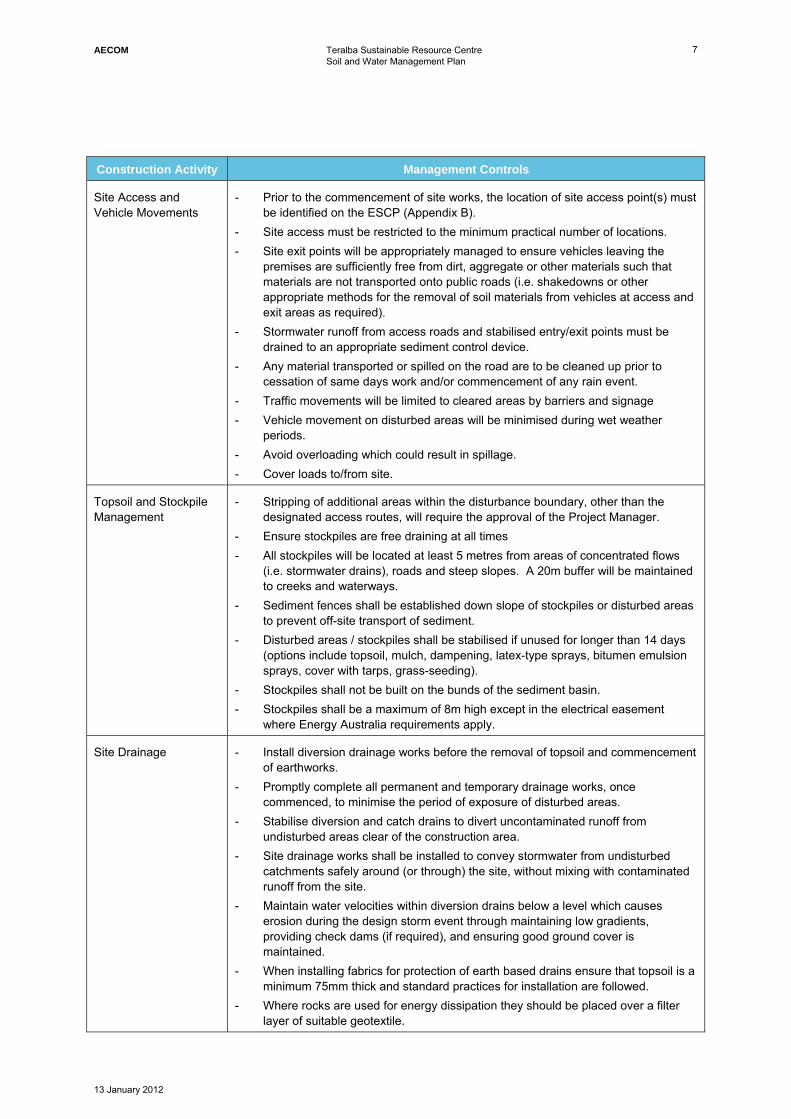
Construction Activity Management Controls
Site Access and Vehicle Movements
- Prior to the commencement of site works, the location of site access point(s) must be identified on the ESCP (Appendix B).
- Site access must be restricted to the minimum practical number of locations. - Site exit points will be appropriately managed to ensure vehicles leaving the
premises are sufficiently free from dirt, aggregate or other materials such that materials are not transported onto public roads (i.e. shakedowns or other appropriate methods for the removal of soil materials from vehicles at access and exit areas as required).
- Stormwater runoff from access roads and stabilised entry/exit points must be drained to an appropriate sediment control device.
- Any material transported or spilled on the road are to be cleaned up prior to cessation of same days work and/or commencement of any rain event.
- Traffic movements will be limited to cleared areas by barriers and signage - Vehicle movement on disturbed areas will be minimised during wet weather
periods. - Avoid overloading which could result in spillage. - Cover loads to/from site.
Topsoil and Stockpile Management
- Stripping of additional areas within the disturbance boundary, other than the designated access routes, will require the approval of the Project Manager.
- Ensure stockpiles are free draining at all times - All stockpiles will be located at least 5 metres from areas of concentrated flows
(i.e. stormwater drains), roads and steep slopes. A 20m buffer will be maintained to creeks and waterways.
- Sediment fences shall be established down slope of stockpiles or disturbed areas to prevent off-site transport of sediment.
- Disturbed areas / stockpiles shall be stabilised if unused for longer than 14 days (options include topsoil, mulch, dampening, latex-type sprays, bitumen emulsion sprays, cover with tarps, grass-seeding).
- Stockpiles shall not be built on the bunds of the sediment basin. - Stockpiles shall be a maximum of 8m high except in the electrical easement
where Energy Australia requirements apply.
Site Drainage - Install diversion drainage works before the removal of topsoil and commencement of earthworks.
- Promptly complete all permanent and temporary drainage works, once commenced, to minimise the period of exposure of disturbed areas.
- Stabilise diversion and catch drains to divert uncontaminated runoff from undisturbed areas clear of the construction area.
- Site drainage works shall be installed to convey stormwater from undisturbed catchments safely around (or through) the site, without mixing with contaminated runoff from the site.
- Maintain water velocities within diversion drains below a level which causes erosion during the design storm event through maintaining low gradients, providing check dams (if required), and ensuring good ground cover is maintained.
- When installing fabrics for protection of earth based drains ensure that topsoil is a minimum 75mm thick and standard practices for installation are followed.
- Where rocks are used for energy dissipation they should be placed over a filter layer of suitable geotextile.
AECOM Teralba Sustainable Resource Centre Soil and Water Management Plan
13 January 2012
8
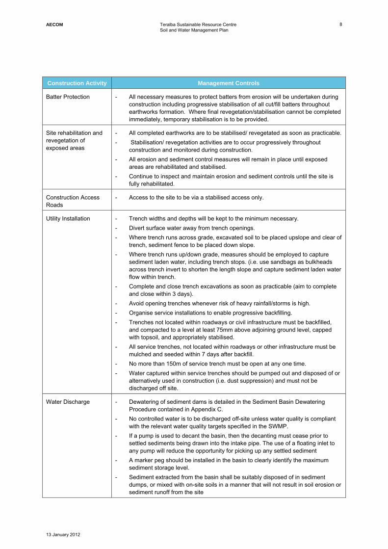
Construction Activity Management Controls
Batter Protection - All necessary measures to protect batters from erosion will be undertaken during construction including progressive stabilisation of all cut/fill batters throughout earthworks formation. Where final revegetation/stabilisation cannot be completed immediately, temporary stabilisation is to be provided.
Site rehabilitation and revegetation of exposed areas
- All completed earthworks are to be stabilised/ revegetated as soon as practicable. - Stabilisation/ revegetation activities are to occur progressively throughout
construction and monitored during construction. - All erosion and sediment control measures will remain in place until exposed
areas are rehabilitated and stabilised. - Continue to inspect and maintain erosion and sediment controls until the site is
fully rehabilitated.
Construction Access Roads
- Access to the site to be via a stabilised access only.
Utility Installation - Trench widths and depths will be kept to the minimum necessary. - Divert surface water away from trench openings. - Where trench runs across grade, excavated soil to be placed upslope and clear of
trench, sediment fence to be placed down slope. - Where trench runs up/down grade, measures should be employed to capture
sediment laden water, including trench stops. (i.e. use sandbags as bulkheads across trench invert to shorten the length slope and capture sediment laden water flow within trench.
- Complete and close trench excavations as soon as practicable (aim to complete and close within 3 days).
- Avoid opening trenches whenever risk of heavy rainfall/storms is high. - Organise service installations to enable progressive backfilling. - Trenches not located within roadways or civil infrastructure must be backfilled,
and compacted to a level at least 75mm above adjoining ground level, capped with topsoil, and appropriately stabilised.
- All service trenches, not located within roadways or other infrastructure must be mulched and seeded within 7 days after backfill.
- No more than 150m of service trench must be open at any one time. - Water captured within service trenches should be pumped out and disposed of or
alternatively used in construction (i.e. dust suppression) and must not be discharged off site.
Water Discharge - Dewatering of sediment dams is detailed in the Sediment Basin Dewatering Procedure contained in Appendix C.
- No controlled water is to be discharged off-site unless water quality is compliant with the relevant water quality targets specified in the SWMP.
- If a pump is used to decant the basin, then the decanting must cease prior to settled sediments being drawn into the intake pipe. The use of a floating inlet to any pump will reduce the opportunity for picking up any settled sediment
- A marker peg should be installed in the basin to clearly identify the maximum sediment storage level.
- Sediment extracted from the basin shall be suitably disposed of in sediment dumps, or mixed with on-site soils in a manner that will not result in soil erosion or sediment runoff from the site
AECOM Teralba Sustainable Resource Centre Soil and Water Management Plan
13 January 2012
9
Construction Activity Management Controls
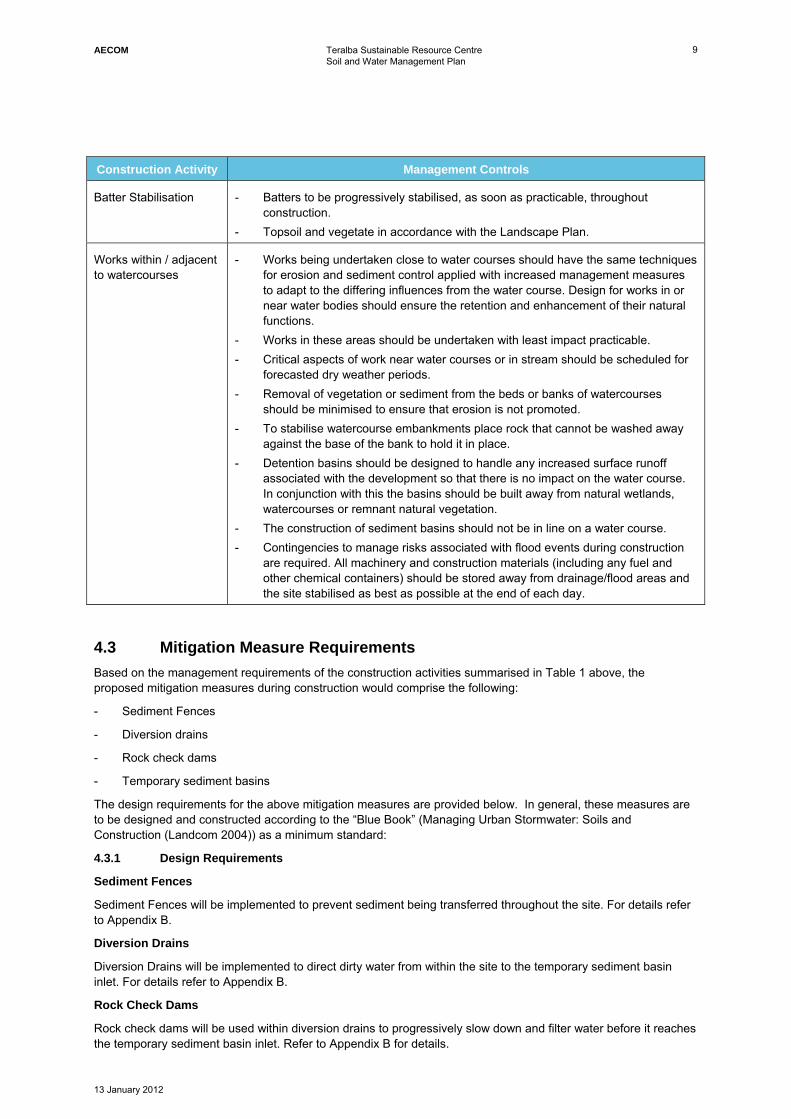
Batter Stabilisation - Batters to be progressively stabilised, as soon as practicable, throughout construction.
- Topsoil and vegetate in accordance with the Landscape Plan.
Works within / adjacent to watercourses
- Works being undertaken close to water courses should have the same techniques for erosion and sediment control applied with increased management measures to adapt to the differing influences from the water course. Design for works in or near water bodies should ensure the retention and enhancement of their natural functions.
- Works in these areas should be undertaken with least impact practicable. - Critical aspects of work near water courses or in stream should be scheduled for
forecasted dry weather periods. - Removal of vegetation or sediment from the beds or banks of watercourses
should be minimised to ensure that erosion is not promoted. - To stabilise watercourse embankments place rock that cannot be washed away
against the base of the bank to hold it in place. - Detention basins should be designed to handle any increased surface runoff
associated with the development so that there is no impact on the water course. In conjunction with this the basins should be built away from natural wetlands, watercourses or remnant natural vegetation.
- The construction of sediment basins should not be in line on a water course. - Contingencies to manage risks associated with flood events during construction
are required. All machinery and construction materials (including any fuel and other chemical containers) should be stored away from drainage/flood areas and the site stabilised as best as possible at the end of each day.
4.3 Mitigation Measure Requirements Based on the management requirements of the construction activities summarised in Table 1 above, the proposed mitigation measures during construction would comprise the following:
- Sediment Fences
- Diversion drains
- Rock check dams
- Temporary sediment basins
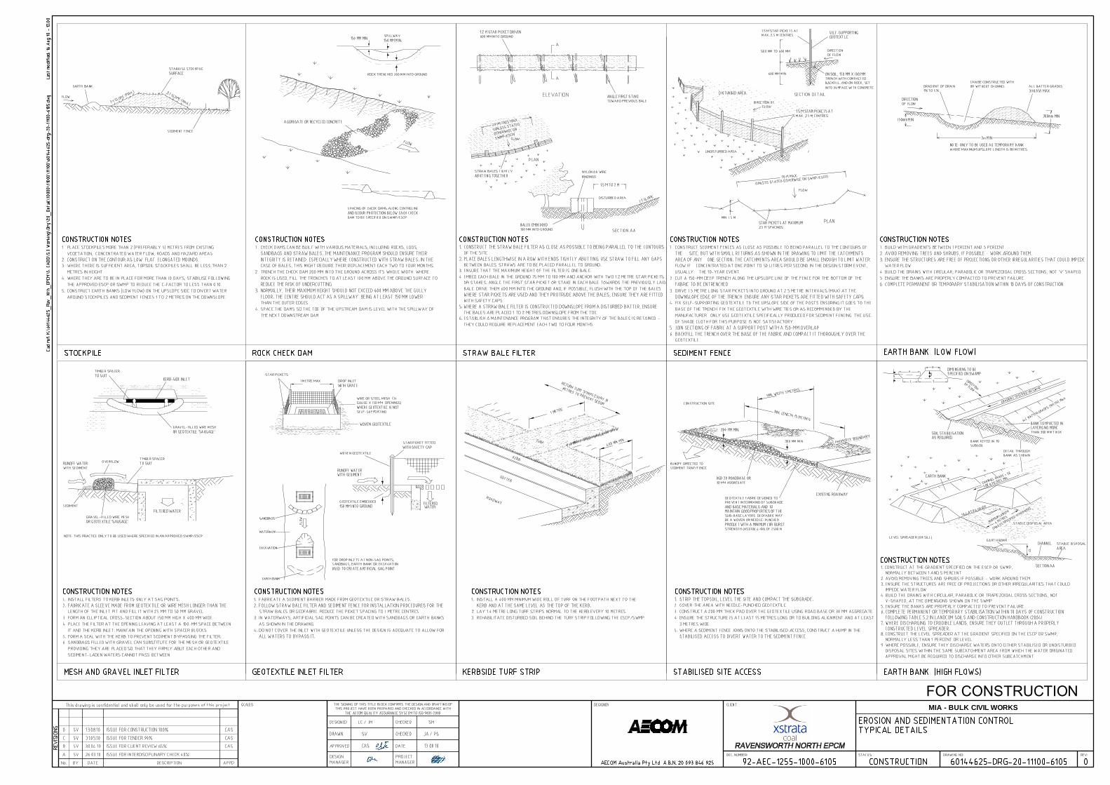
The design requirements for the above mitigation measures are provided below. In general, these measures are to be designed and constructed according to the “Blue Book” (Managing Urban Stormwater: Soils and Construction (Landcom 2004)) as a minimum standard:
4.3.1 Design Requirements
Sediment Fences
Sediment Fences will be implemented to prevent sediment being transferred throughout the site. For details refer to Appendix B.
Diversion Drains
Diversion Drains will be implemented to direct dirty water from within the site to the temporary sediment basin inlet. For details refer to Appendix B.
Rock Check Dams
Rock check dams will be used within diversion drains to progressively slow down and filter water before it reaches the temporary sediment basin inlet. Refer to Appendix B for details.
AECOM Teralba Sustainable Resource Centre Soil and Water Management Plan
13 January 2012
10
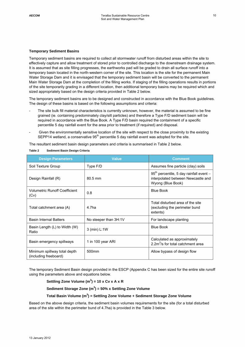
Temporary Sediment Basins
Temporary sediment basins are required to collect all stormwater runoff from disturbed areas within the site to effectively capture and allow treatment of stored prior to controlled discharge to the downstream drainage system. It is assumed that as site filling progresses, the earthworks pad will be graded to drain all surface runoff into a temporary basin located in the north-western corner of the site. This location is the site for the permanent Main Water Storage Dam and it is envisaged that the temporary sediment basin will be converted to the permanent Main Water Storage Dam at the completion of the filling works. If staging of the filling operations results in portions of the site temporarily grading in a different location, then additional temporary basins may be required which and sized appropriately based on the design criteria provided in Table 2 below.
The temporary sediment basins are to be designed and constructed in accordance with the Blue Book guidelines. The design of these basins is based on the following assumptions and criteria:
- The site bulk fill material characteristics is currently unknown, however, the material is assumed to be fine grained (ie. containing predominately clay/silt particles) and therefore a Type F/D sediment basin will be required in accordance with the Blue Book. A Type F/D basin required the containment of a specific percentile 5 day rainfall event for the area prior to treatment (if required) and disposal.
- Given the environmentally sensitive location of the site with respect to the close proximity to the existing SEPP14 wetland, a conservative 95th percentile 5 day rainfall event was adopted for the site.
The resultant sediment basin design parameters and criteria is summarised in Table 2 below. Table 2 Sediment Basin Design Criteria
Design Parameters Value Comment
Soil Texture Group Type F/D Assumes fine particle (clay) soils
Design Rainfall (R) 80.5 mm 95th percentile, 5 day rainfall event – interpolated between Newcastle and Wyong (Blue Book)
Volumetric Runoff Coefficient (Cv) 0.8 Blue Book
Total catchment area (A) 4.7ha Total disturbed area of the site (excluding the perimeter bund extents)
Basin Internal Batters No steeper than 3H:1V For landscape planting
Basin Length (L) to Width (W) Ratio 3 (min) L:1W Blue Book
Basin emergency spillways 1 in 100 year ARI Calculated as approximately 2.2m3/s for total catchment area
Minimum spillway total depth (including freeboard)
500mm Allow bypass of design flow
The temporary Sediment Basin design provided in the ESCP (Appendix C has been sized for the entire site runoff using the parameters above and equations below.
Settling Zone Volume (m3) = 10 x Cv x A x R
Sediment Storage Zone (m3) = 50% x Settling Zone Volume
Total Basin Volume (m3) = Settling Zone Volume + Sediment Storage Zone Volume
Based on the above design criteria, the sediment basin volumes requirements for the site (for a total disturbed area of the site within the perimeter bund of 4.7ha) is provided in the Table 3 below.
AECOM Teralba Sustainable Resource Centre Soil and Water Management Plan
13 January 2012
11
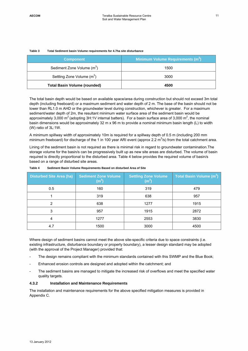
Table 3 Total Sediment basin Volume requirements for 4.7ha site disturbance
Component Minimum Volume Requirements (m3)
Sediment Zone Volume (m3) 1500
Settling Zone Volume (m3) 3000
Total Basin Volume (rounded) 4500
The total basin depth would be based on available space/area during construction but should not exceed 3m total depth (including freeboard) or a maximum sediment and water depth of 2 m. The base of the basin should not be lower than RL1.0 m AHD or the groundwater level during construction, whichever is greater. For a maximum sediment/water depth of 2m, the resultant minimum water surface area of the sediment basin would be approximately 3,000 m2 (adopting 3H:1V internal batters). For a basin surface area of 3,000 m2, the nominal basin dimensions would be approximately 32 m x 96 m to provide a nominal minimum basin length (L) to width (W) ratio of 3L:1W.
A minimum spillway width of approximately 10m is required for a spillway depth of 0.5 m (including 200 mm minimum freeboard) for discharge of the 1 in 100 year ARI event (approx 2.2 m3/s) from the total catchment area.
Lining of the sediment basin is not required as there is minimal risk in regard to groundwater contamination.The storage volume for the basin/s can be progressively built up as new site areas are disturbed. The volume of basin required is directly proportional to the disturbed area. Table 4 below provides the required volume of basin/s based on a range of disturbed site areas. Table 4 Sediment Basin Volume Requirements Based on disturbed Area of Site
Disturbed Site Area (ha) Sediment Zone Volume (m3)
Settling Zone Volume (m3)
Total Basin Volume (m3)
0.5 160 319 479
1 319 638 957
2 638 1277 1915
3 957 1915 2872
4 1277 2553 3830
4.7 1500 3000 4500
Where design of sediment basins cannot meet the above site-specific criteria due to space constraints (i.e. existing infrastructure, disturbance boundary or property boundary), a lesser design standard may be adopted (with the approval of the Project Manager) provided that:
- The design remains compliant with the minimum standards contained with this SWMP and the Blue Book;
- Enhanced erosion controls are designed and adopted within the catchment; and
- The sediment basins are managed to mitigate the increased risk of overflows and meet the specified water quality targets.
4.3.2 Installation and Maintenance Requirements
The installation and maintenance requirements for the above specified mitigation measures is provided in Appendix C.
AECOM Teralba Sustainable Resource Centre Soil and Water Management Plan
13 January 2012
12
5.0 SWMP Implementation
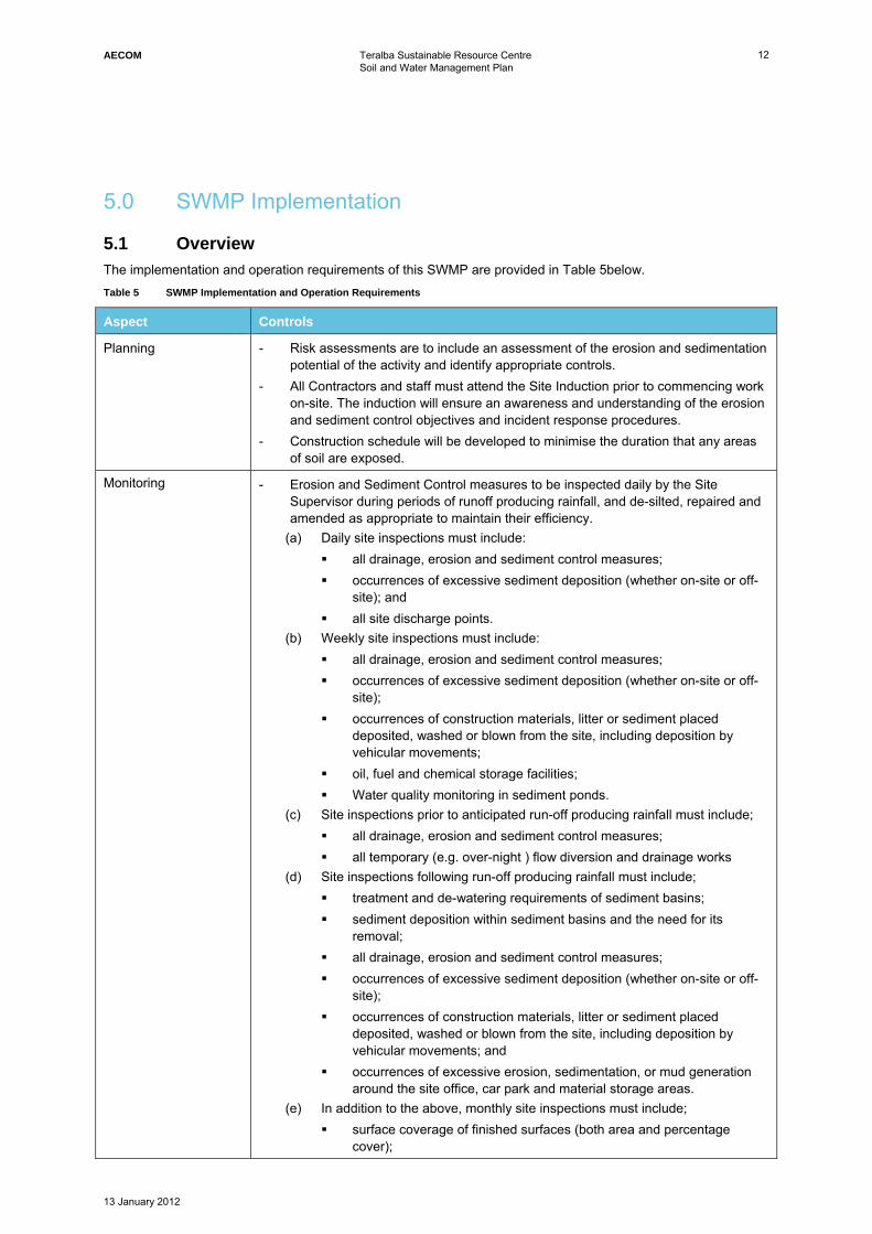
5.1 Overview The implementation and operation requirements of this SWMP are provided in Table 5below. Table 5 SWMP Implementation and Operation Requirements
Aspect Controls
Planning - Risk assessments are to include an assessment of the erosion and sedimentation potential of the activity and identify appropriate controls.
- All Contractors and staff must attend the Site Induction prior to commencing work on-site. The induction will ensure an awareness and understanding of the erosion and sediment control objectives and incident response procedures.
- Construction schedule will be developed to minimise the duration that any areas of soil are exposed.
Monitoring
- Erosion and Sediment Control measures to be inspected daily by the Site Supervisor during periods of runoff producing rainfall, and de-silted, repaired and amended as appropriate to maintain their efficiency.
(a) Daily site inspections must include: all drainage, erosion and sediment control measures; occurrences of excessive sediment deposition (whether on-site or off-
site); and all site discharge points.
(b) Weekly site inspections must include: all drainage, erosion and sediment control measures; occurrences of excessive sediment deposition (whether on-site or off-
site); occurrences of construction materials, litter or sediment placed
deposited, washed or blown from the site, including deposition by vehicular movements;
oil, fuel and chemical storage facilities; Water quality monitoring in sediment ponds.
(c) Site inspections prior to anticipated run-off producing rainfall must include; all drainage, erosion and sediment control measures; all temporary (e.g. over-night ) flow diversion and drainage works
(d) Site inspections following run-off producing rainfall must include; treatment and de-watering requirements of sediment basins; sediment deposition within sediment basins and the need for its
removal; all drainage, erosion and sediment control measures; occurrences of excessive sediment deposition (whether on-site or off-
site); occurrences of construction materials, litter or sediment placed
deposited, washed or blown from the site, including deposition by vehicular movements; and
occurrences of excessive erosion, sedimentation, or mud generation around the site office, car park and material storage areas.
(e) In addition to the above, monthly site inspections must include; surface coverage of finished surfaces (both area and percentage
cover);
AECOM Teralba Sustainable Resource Centre Soil and Water Management Plan
13 January 2012
13
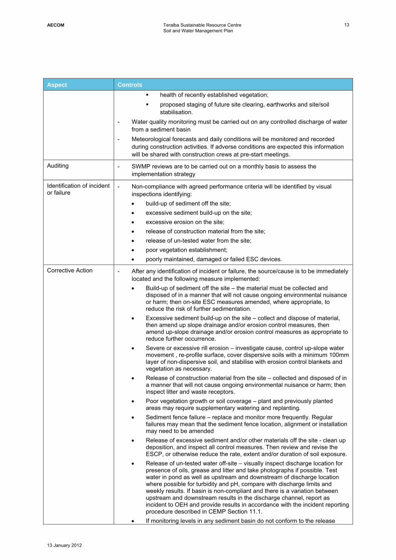
Aspect Controls health of recently established vegetation; proposed staging of future site clearing, earthworks and site/soil
stabilisation. - Water quality monitoring must be carried out on any controlled discharge of water
from a sediment basin - Meteorological forecasts and daily conditions will be monitored and recorded
during construction activities. If adverse conditions are expected this information will be shared with construction crews at pre-start meetings.
Auditing
- SWMP reviews are to be carried out on a monthly basis to assess the implementation strategy
Identification of incident or failure
- Non-compliance with agreed performance criteria will be identified by visual inspections identifying: • build-up of sediment off the site; • excessive sediment build-up on the site; • excessive erosion on the site; • release of construction material from the site; • release of un-tested water from the site; • poor vegetation establishment; • poorly maintained, damaged or failed ESC devices.
Corrective Action
- After any identification of incident or failure, the source/cause is to be immediately located and the following measure implemented: • Build-up of sediment off the site – the material must be collected and
disposed of in a manner that will not cause ongoing environmental nuisance or harm; then on-site ESC measures amended, where appropriate, to reduce the risk of further sedimentation.
• Excessive sediment build-up on the site – collect and dispose of material, then amend up slope drainage and/or erosion control measures, then amend up-slope drainage and/or erosion control measures as appropriate to reduce further occurrence.
• Severe or excessive rill erosion – investigate cause, control up-slope water movement , re-profile surface, cover dispersive soils with a minimum 100mm layer of non-dispersive soil, and stabilise with erosion control blankets and vegetation as necessary.
• Release of construction material from the site – collected and disposed of in a manner that will not cause ongoing environmental nuisance or harm; then inspect litter and waste receptors.
• Poor vegetation growth or soil coverage – plant and previously planted areas may require supplementary watering and replanting.
• Sediment fence failure – replace and monitor more frequently. Regular failures may mean that the sediment fence location, alignment or installation may need to be amended
• Release of excessive sediment and/or other materials off the site - clean up deposition, and inspect all control measures. Then review and revise the ESCP, or otherwise reduce the rate, extent and/or duration of soil exposure.
• Release of un-tested water off-site – visually inspect discharge location for presence of oils, grease and litter and take photographs if possible. Test water in pond as well as upstream and downstream of discharge location where possible for turbidity and pH, compare with discharge limits and weekly results. If basin is non-compliant and there is a variation between upstream and downstream results in the discharge channel, report as incident to OEH and provide results in accordance with the incident reporting procedure described in CEMP Section 11.1.
• If monitoring levels in any sediment basin do not conform to the release
AECOM Teralba Sustainable Resource Centre Soil and Water Management Plan
13 January 2012
14
Aspect Controls criteria for; a) TSS – flocculate as per determined flocculation procedure and re-test; b) pH –dose with hydrated lime if pH is too low, and retest. If still does not comply then consider options which may include further re-dosing with flocculent / lime or offsite disposal by tanker to an appropriate facility.
Reporting - As detailed in Section 10.1 in CEMP.
5.2 Inspection Requirements The site inspections should consider how the individual erosion and sediment controls act as part of a whole system and the individual performance of each ultimately determines the success or malfunction of the system.
5.2.1 Pre-Inspection
Items which should be reviewed / understood before conducting a site inspection are as follows:
- Legislation required by the governing body to be adhered to by site; and
- Policies and guidelines specific to the project should be reviewed to check they are being followed; and
- Aim of the erosion and sediment control plan, to ensure that what is implemented on site as per the plan is suitable; and
- Practices and operations being used on site (this includes and is not limited to client-specific as well as contractor-specific procedures and operations relevant to the project); and
- Weather forecast and construction schedule should be assessed to ensure the inspection is not being carried out at an inappropriate or unsafe time; and
- Plans for construction to gain an understanding of project; and
- Compliance history to allow an understanding of where the project may be lacking or has improved.
5.2.2 Scope
Ideally the full site should be inspected; however, where this is too large and packages of work are being carried out the area of current development should be covered.
Appendix H of the CEMP contains a template for site inspections. These are prompts and as site specific items are observed, these should be noted in the additional comments section of the inspection checklist.
The site inspection report should:
- Note where an ESC is not appropriate and where it may need an amendment or additional information;
- Focus on the good and bad practices as well as identify where aspects of erosion and sediment control are critical within any given works;
- Record all non conformances, maintenance and amendments necessary to achieve and/or maintain the required treatment and performance standard;
If an inspection is not carried out according to the inspection schedule then this should also be reported and recorded with justification as to why the inspection did not occur.
5.2.3 Non-Conformance and Corrective Actions
Refer to Section 12 of the CEMP for Non-conformance and Corrective Action procedures to be followed. For incident response procedures, refer to Section 11 of the CEMP.
AECOM Teralba Sustainable Resource Centre Soil and Water Management Plan
13 January 2012
15
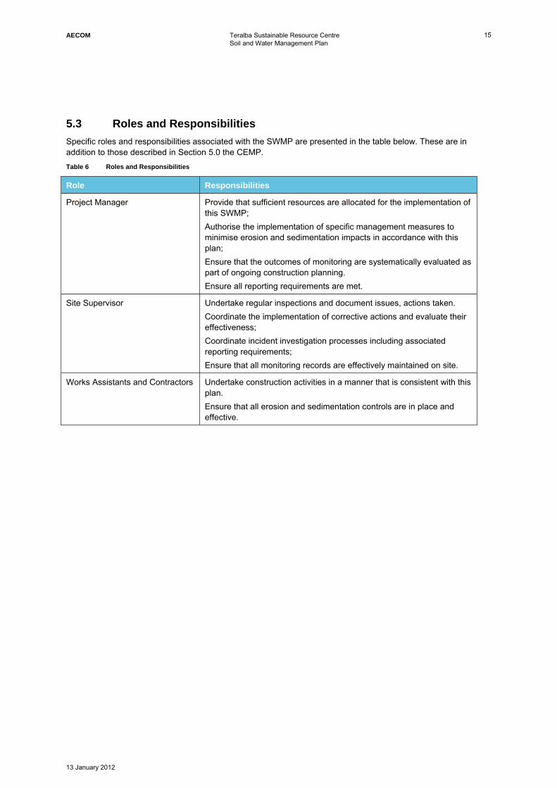
5.3 Roles and Responsibilities Specific roles and responsibilities associated with the SWMP are presented in the table below. These are in addition to those described in Section 5.0 the CEMP. Table 6 Roles and Responsibilities
Role Responsibilities
Project Manager Provide that sufficient resources are allocated for the implementation of this SWMP; Authorise the implementation of specific management measures to minimise erosion and sedimentation impacts in accordance with this plan; Ensure that the outcomes of monitoring are systematically evaluated as part of ongoing construction planning. Ensure all reporting requirements are met.
Site Supervisor Undertake regular inspections and document issues, actions taken. Coordinate the implementation of corrective actions and evaluate their effectiveness; Coordinate incident investigation processes including associated reporting requirements; Ensure that all monitoring records are effectively maintained on site.
Works Assistants and Contractors Undertake construction activities in a manner that is consistent with this plan. Ensure that all erosion and sedimentation controls are in place and effective.
AECOM Teralba Sustainable Resource Centre Soil and Water Management Plan
13 January 2012
Appendix A
Receiving Environment Plan
1
174
191
16
203
202
205
196
198
200
201
198
198
191
192
194
193
195
111
751
681
791
771
7970
1.891
861
78
179
180
178
125
121
133
51
194
1
175
12
061
17
193
6
1 99
210
2022
12
196
1.00
1.00
2.00
2.00
2.00
111111.89111111
681111111
64646
11111172
111111162626
00000000061
67
0049
0036
43
0052525
1196
1183
45
2283
1195
1192929
222222
2
966
22
2
2
66
2.00
22222222222222282828
244444
66
22222222251
22222233
2.00
33 3332
22288
229
2299999
2222
224
5757
3.00
34343
2213
09
2222222402222222
42
09
2234343
213
224
2
772
7722
323222
922
2922222222222222
32
13
3222 632
2263
22
3 66322
32
22222230
22222222240
22222227111111
82828222222222222
16
222
22
2245
6999
0067
34343
2213
4
3
00
52525
0
23
2
444444
2222222216
240
2
98
2222222
22233
40
23
223
2277
2244444
66
2263
22229
2322
44
0000
2
4
228
22
5722
99
32
3
3 00
4
11
6969699
27
3
222
TRANSMISSIONTOW
ER
1
1 761 741 91
1 6
2 032 022 05
1 961 98
2 002 01
1 981 98
1 911 92
1 941 93
1 9511
1 751 68
1 791 77
1 79 70
1.891 86
1 78
1 791 80
1 801 78
1 74
1 09
1 090 810 83
0 720 61
0 520 59
0 670 39
0 760 340 30
1 681 64
1 541 251 21
1 3351
1 94
2 55
2 79
2 69
1
2 40
1 35
1 72
175
1 62
2 842 41
2 522 30
12
0 61
2 10
2 53
2 35
2 16
0 58
0 67
0 57
0 49
0 36 0 43
0 52
0 4
0 59
1 96
1 83
1 060 69
2 42
2 54
2 45
2 39
1 53
2 242 16
2 112 13
2 77
2 442 34
2 21
2 132 09
2 99
3 32
2 88
2 43
1 92
2 472 57
2 993 07
3 11
2 66
2 63
1 781 70
1 93
6
1 99
2 452 32
2 49
2 072 30
2 66
2 29
2 192 63
2 40
2 33
2 23
2 34
2 402 42
2 27
1 91
2 08
1 82
2 00
2 16
2 74
2 20
2 23
2 28
2 29
2 44
2 25
2 33
2 25
2 38
0 73
2 102 022 12
1 961 84
1 64
1 45
1 48
1.00
1.00
1.00
1.00
1.00
2.00
2.00
2.00
2.00
2.00
2.00
2.00
2.00
2.00
2.002.00
2.00
2.00
2.00
2.00
3.00
Appendix A1 Plan View Receiving Environment
TRANSMISSIONTOW
ER
1
176
174
191
16
203
202
205
196
198
200
201
198
198
191
192
194
193
195
111
751
681
791
771
7970
1.891
861
78
179
180
180
178
174
109
109
081
083
072
061
052
059
067
039
076
034
030
168
164
154
125
121
133
51
194
2 65
2 70
2 44
2 55
2 79
2 69
2 291
2 40
260
2 82
2 89
2 53
135
172
175
162
284
241
252
230
12
061
210
253
235
216
058
067
057
049
036 0
43
052
04
059
215
195
196
183
106
069
242
254
245
239
234
153
283
195
192
2 242 16
2 112 42
2 362 13
2 77
2 442 34
2 21
2 132 09
2 20
2 99
3 32
2 88
2 43
1 92
2 472 57
2 993 07
3 11
2 66
2 63
178
170
193
6
1 99
245
232
249
207
230
266
2 292 51
219
2 63
263
248
240
245
233
216
223
234
2402
42
227
191
208
182
200
216
274
220
223
228
229
244
225
233
2 25
238
073
210
2022
12
196
184
164
145
1 48
1.00
1.00
1.00
1.00
1.00
2.00
2.00
2.00
2.00
2.00
2.00
2.00
2.00
2.00
2.00
2.002.00
2.00
2.00
2.00
2.00
2.00
3.00
SEPP 14 wetland boundary
TRANSMISSIONTOW
ER
1
176
174
191
16
203
202
205
196
198
200
201
198
198
191
192
194
193
195
111
751
681
791
771
7970
1.891
861
78
179
180
180
178
174
109
109
081
083
072
061
052
059
067
039
076
034
030
168
164
154
125
121
133
51
194
2 65
2 70
2 44
2 55
2 79
2 69
2 291
2 40
260
2 82
2 89
2 53
135
172
175
162
284
241
252
230
12
061
210
253
235
216
058
067
057
049
036 0
43
052
04
059
215
195
196
183
106
069
242
254
245
239
234
153
283
195
192
2 242 16
2 112 42
2 362 13
2 77
2 442 34
2 21
2 132 09
2 20
2 99
3 32
2 88
2 43
1 92
2 472 57
2 993 07
3 11
2 66
2 63
178
170
193
6
1 99
245
232
249
207
230
266
2 292 51
219
2 63
263
248
240
245
233
216
223
234
2402
42
227
191
208
182
200
216
274
220
223
228
229
244
225
233
2 25
238
073
210
2022
12
196
184
164
145
1 48
1.00
1.00
1.00
1.00
1.00
2.00
2.00
2.00
2.00
2.00
2.00
2.00
2.00
2.00
2.00
2.002.00
2.00
2.00
2.00
2.00
2.00
3.00
Freshwater wetland
boundary
TRANSMISSIONTOW
ER
1
176
174
191
16
203
202
205
196
198
200
201
198
198
191
192
194
193
195
111
751
681
791
771
7970
1.891
861
78
179
180
180
178
174
109
109
081
083
072
061
052
059
067
039
076
034
030
168
164
154
125
121
133
51
194
2 65
2 70
2 44
2 55
2 79
2 69
2 291
2 40
260
2 82
2 89
2 53
135
172
175
162
284
241
252
230
12
061
210
253
235
216
058
067
057
049
036 0
43
052
04
059
215
195
196
183
106
069
242
254
245
239
234
153
283
195
192
2 242 16
2 112 42
2 362 13
2 77
2 442 34
2 21
2 132 09
2 20
2 99
3 32
2 88
2 43
1 92
2 472 57
2 993 07
3 11
2 66
2 63
178
170
193
6
1 99
245
232
249
207
230
266
2 292 51
219
2 63
263
248
240
245
233
216
223
234
2402
42
227
191
208
182
200
216
274
220
223
228
229
244
225
233
2 25
238
073
210
2022
12
196
184
164
145
1 48
1.00
1.00
1.00
1.00
1.00
2.00
2.00
2.00
2.00
2.00
2.00
2.00
2.00
2.00
2.00
2.002.00
2.00
2.00
2.00
2.00
2.00
3.00
Site boundaryTRANSMISSIONTOW
ER
1
176
174
191
16
203
202
205
196
198
200
201
198
198
191
192
194
193
195
111
751
681
791
771
7970
1.891
861
78
179
180
180
178
174
109
109
081
083
072
061
052
059
067
039
076
034
030
168
164
154
125
121
133
51
194
2 65
2 70
2 44
2 55
2 79
2 69
2 291
2 40
260
2 82
2 89
2 53
135
172
175
162
284
241
252
230
12
061
210
253
235
216
058
067
057
049
036 0
43
052
04
059
215
195
196
183
106
069
242
254
245
239
234
153
283
195
192
2 242 16
2 112 42
2 362 13
2 77
2 442 34
2 21
2 132 09
2 20
2 99
3 32
2 88
2 43
1 92
2 472 57
2 993 07
3 11
2 66
2 63
178
170
193
6
1 99
245
232
249
207
230
266
2 292 51
219
2 63
263
248
240
245
233
216
223
234
2402
42
227
191
208
182
200
216
274
220
223
228
229
244
225
233
2 25
238
073
210
2022
12
196
184
164
145
1 48
1.00
1.00
1.00
1.00
1.00
2.00
2.00
2.00
2.00
2.00
2.00
2.00
2.00
2.00
2.00
2.002.00
2.00
2.00
2.00
2.00
2.00
3.00
Site runoff drains to Freshwater wetland
Legend
Plan View Receiving Environment
Th
e W
eir
Ro
ad
Plan View Site
Sediment deposition pond
Swamp Mahogany / Paperbark / Woollybutt Swamp Forest
Bioretention system Ball Honeymyrtle Swamp Forest
Water storage pond Forest Red Gum / Woollybutt / Mahogany Floodplain Forest
Clean water pondsFreshwater Wetland
Legend
Plan View Site
Endangered Ecological Communities
Water flow / treatment direction
Water flow / treatment direction
Transfer to additional water storage ponds
High flow bypass
Legend
Endangered Ecological Communities (map from Ecotone report)
Angophora inopina
Flora Quadrat
Discharge Pathway
TRANSMISSIONTOW
ER
1
1 761 741 91
1 6
2 032 022 05
1 961 98
2 002 01
1 981 98
1 911 92
1 941 93
1 9511
1 751 68
1 791 77
1 79 70
1.891 86
1 78
1 791 80
1 801 78
1 74
1 09
1 090 810 83
0 720 61
0 520 59
0 670 39
0 760 340 30
1 681 64
1 541 251 21
1 3351
1 94
2 55
2 79
2 69
1
2 40
1 35
1 72
175
1 62
2 842 41
2 522 30
12
0 61
2 10
2 53
2 35
2 16
0 58
0 67
0 57
0 49
0 36 0 43
0 52
0 4
0 59
1 96
1 83
1 060 69
2 42
2 54
2 45
2 39
1 53
2 242 16
2 112 13
2 77
2 442 34
2 21
2 132 09
2 99
3 32
2 88
2 43
1 92
2 472 57
2 993 07
3 11
2 66
2 63
1 781 70
1 93
6
1 99
2 452 32
2 49
2 072 30
2 66
2 29
2 192 63
2 40
2 33
2 23
2 34
2 402 42
2 27
1 91
2 08
1 82
2 00
2 16
2 74
2 20
2 23
2 28
2 29
2 44
2 25
2 33
2 25
2 38
0 73
2 102 022 12
1 961 84
1 64
1 45
1 48
1.00
1.00
1.00
1.00
1.00
2.00
2.00
2.00
2.00
2.00
2.00
2.00
2.00
2.00
2.002.00
2.00
2.00
2.00
2.00
3.00

AECOM Teralba Sustainable Resource Centre Soil and Water Management Plan
13 January 2012
Appendix B
Erosion and Sediment Control Plan (ESCP) and Typical Details


TRANSMISSION
TOWER
1
1 761 741 91
1 68
2 032 02
2 051 961 98
2 002 01
1 981 98
1 911 92
1 941 93
1 95
1 91
1 75
1 68
1 79
1 77
1 79 70
1.891 86
1 781 79
1 801 80
1 781 74
1 091 090 81
0 830 720 61
0 520 59
0 670 39
0 760 340 30
1 68
1 64
1 54
1 251 21
1 3351
1 94
2 652 702 442 552 79
2 692 29
1
2 402 602 822 892 53
1 35
1 721 75
1 62
2 84
2 41
2 52
2 30
1 2
0 61
2 10
2 53
2 35
2 160 58
0 67
0 57
0 49
0 36
0 43
0 52
0 49
0 59
2 15
1 95
1 96
1 83
1 06
0 69
2 42
2 54
2 45
2 39
2 34
1 53
2 83
1 95
1 92
2 24
2 162 11
2 42
2 36
2 13 2 772 44
2 342 21
2 13
2 09
2 20
2 99
3 322 88
2 431 922 47
2 57
2 99
3 07
3 11
2 662 63
1 781 70
1 93
6
1 99
2 45
2 322 49
2 49
2 07
2 30
2 66
2 29
2 51
2 19
2 63
2 63
2 48
2 40
2 45
2 33
1 19
2 16
2 23
2 341 98
2 40
2 42
2 27
1 91
2 08
1 82
2 00
2 162 74
2 20
2 23
2 28
2 29
2 44 2 25
2 33
2 252 380 73
2 102 02
2 12
1 961 84
1 64
1 45
1 48
2 93
1.00
1.00
1.00
1.00 1.00
2.00
2.00
2.00
2.00
2.00
2.00
2.00
2.00
2.00
2.00
2.00
2.00
2.00
2.00
2.00
2.00
2.00
3.00
TERALBA SUSTAINABLE RESOURCE CENTRE
REVISION
IN PROGRESS
CHECK PRINTCHECK PRINT

FOR CONSTRUCTIONMIA - BULK CIVIL WORKS

AECOM Teralba Sustainable Resource Centre Soil and Water Management Plan
13 January 2012
Appendix C
Control Measure Installation and Maintenance Guidelines

AECOM
1
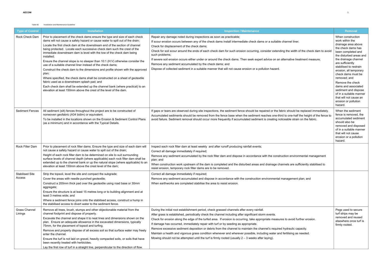
Table B1 Installation and Maintenance Guideline
Type of Control Installation Inspection / Maintenance Removal
Rock Check Dam Prior to placement of the check dams ensure the type and size of each check dams will not cause a safety hazard or cause water to spill out of the drain; Locate the first check dam at the downstream end of the section of channel being protected. Locate each successive check dam such the crest of the immediate downstream dam is level with the tow of the check dam being installed; Ensure the channel slope is no steeper than 10:1 (H:V) otherwise consider the use of a suitable channel liner instead of the check dams; Construct the check dam to the dimensions and profile shown with the approved plan; Where specified, the check dams shall be constructed on a sheet of geotextile fabric used as a downstream splash pad; and Each check dam shall be extended up the channel bank (where practical) to an elevation at least 150mm above the crest of the level of the dam.
Repair any damage noted during inspections as soon as practicable; If scour erosion occurs between any of the check dams install intermediate check dams or a suitable channel liner; Check for displacement of the check dams; Check for soil scour around the ends of each check dam for such erosion occurring, consider extending the width of the check dam to avoid such problems; If severe soil erosion occurs either under or around the check dams. Then seek expert advice on an alternative treatment measure; Remove any sediment accumulated by the check dams; and Dispose of collected sediment in a suitable manner that will not cause erosion or a pollution hazard.
When construction work within the drainage area above the check dams has been completed and the disturbed areas and the drainage channel are sufficiently stabilised to restrain erosion, all temporary check dams must be removed; and Remove the check dams and associated sediment and dispose of in a suitable manner that will not cause an erosion or pollution hazard.
Sediment Fences All sediment (silt) fences throughout the project are to be constructed of nonwoven geofabric (A34 bidim) or equivalent. To be installed in the locations shown on the Erosion & Sediment Control Plans (as a minimum) and in accordance with the Typical Details.
If gaps or tears are observed during site inspections, the sediment fence should be repaired or the fabric should be replaced immediately. Accumulated sediments should be removed from the fence base when the sediment reaches one-third to one-half the height of the fence to avoid failure. Sediment removal should occur more frequently if accumulated sediment is creating noticeable strain on the fabric.
When the sediment fence is removed, the accumulated sediment should also be removed and disposed of in a suitable manner that will not cause erosion or a pollution hazard.
Rock Filter Dam
Prior to placement of rock filter dams. Ensure the type and size of each dam will not cause a safety hazard or cause water to spill out of the drain; Height of each rock filter dam to be determined on site to suit surrounding surface levels of channel depth (where applicable) each rock filter dam shall be extended up to the channel bank or up the natural slope (where applicable) to an elevation at least 150mm above the crest level of the dam;
Inspect each rock filter dam at least weekly and after runoff producing rainfall events; Correct all damage immediately if required; Remove any sediment accumulated by the rock filter dam and dispose in accordance with the construction environmental management plan; and When construction work upstream of the dam is completed and the disturbed areas and drainage channels are sufficiently stabilised to resist erosion, temporary rock filter dams are to be removed.
Stabilised Site Access
Strip the topsoil, level the site and compact the subgrade; Cover the areas with needle punched geotextile; Construct a 200mm thick pad over the geotextile using road base or 30mm aggregate; Ensure the structure is at least 15 metres long or to building alignment and at least 3 metres wide; and Where a sediment fence joins onto the stabilised access, construct a hump in the stabilised access to divert water to the sediment fence.
Correct all damage immediately if required; Remove any sediment accumulated and dispose in accordance with the construction environmental management plan; and When earthworks are completed stabilise the area to resist erosion.
Grass Channel Linings
Remove all trees, brush, stumps and other objectionable material from the channel footprint and dispose of properly. Excavate the channel and shape it to neat lines and dimensions shown on the plan. Ensure an adequate allowance in the excavated dimensions, typically 75mm, for the placement of topsoil and turfing. Remove and properly dispose of all excess soil so that surface water may freely enter the channel. Ensure the turf is not laid on gravel, heavily compacted soils, or soils that have been recently treated with herbicides. Lay the first row of turf in a straight line, perpendicular to the direction of flow.
During the initial root establishment period, check grassed channels after every rainfall. After grass is established, periodically check the channel including after significant storm events. Check for erosion along the edge of the turfed area. If erosion is occurring, take appropriate measures to avoid further erosion. If damage has occurred, immediately repair with turf or by seeding as appropriate. Remove excessive sediment deposition or debris from the channel to maintain the channel’s required hydraulic capacity. Maintain a health and vigorous grass condition whenever and wherever possible, including water and fertilising as needed. Mowing should not be attempted until the turf is firmly rooted (usually 2 – 3 weeks after laying).
Pegs used to secure turf strips may be removed and reused elsewhere once turf is firmly rooted.
AECOM
2
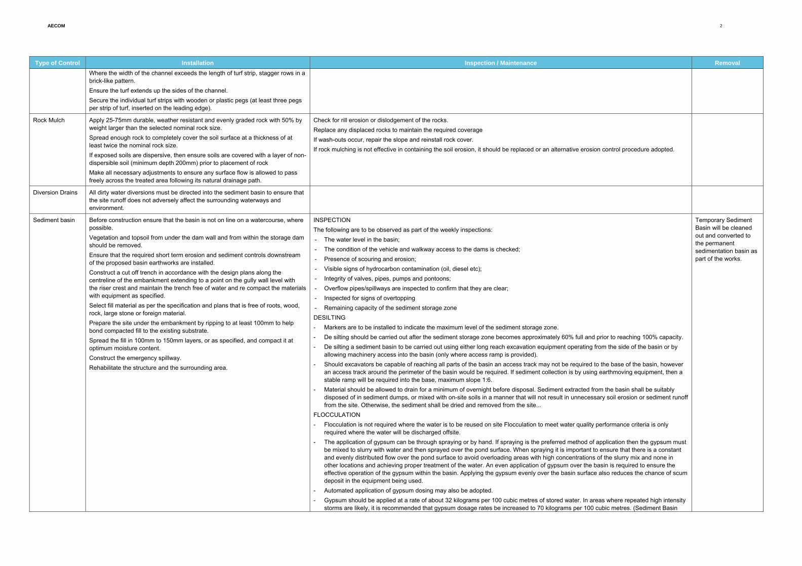
Type of Control Installation Inspection / Maintenance Removal Where the width of the channel exceeds the length of turf strip, stagger rows in a brick-like pattern. Ensure the turf extends up the sides of the channel. Secure the individual turf strips with wooden or plastic pegs (at least three pegs per strip of turf, inserted on the leading edge).
Rock Mulch Apply 25-75mm durable, weather resistant and evenly graded rock with 50% by weight larger than the selected nominal rock size. Spread enough rock to completely cover the soil surface at a thickness of at least twice the nominal rock size. If exposed soils are dispersive, then ensure soils are covered with a layer of non-dispersible soil (minimum depth 200mm) prior to placement of rock Make all necessary adjustments to ensure any surface flow is allowed to pass freely across the treated area following its natural drainage path.
Check for rill erosion or dislodgement of the rocks. Replace any displaced rocks to maintain the required coverage If wash-outs occur, repair the slope and reinstall rock cover. If rock mulching is not effective in containing the soil erosion, it should be replaced or an alternative erosion control procedure adopted.
Diversion Drains All dirty water diversions must be directed into the sediment basin to ensure that the site runoff does not adversely affect the surrounding waterways and environment.
Sediment basin Before construction ensure that the basin is not on line on a watercourse, where possible. Vegetation and topsoil from under the dam wall and from within the storage dam should be removed. Ensure that the required short term erosion and sediment controls downstream of the proposed basin earthworks are installed. Construct a cut off trench in accordance with the design plans along the centreline of the embankment extending to a point on the gully wall level with the riser crest and maintain the trench free of water and re compact the materials with equipment as specified. Select fill material as per the specification and plans that is free of roots, wood, rock, large stone or foreign material. Prepare the site under the embankment by ripping to at least 100mm to help bond compacted fill to the existing substrate. Spread the fill in 100mm to 150mm layers, or as specified, and compact it at optimum moisture content. Construct the emergency spillway. Rehabilitate the structure and the surrounding area.
INSPECTION The following are to be observed as part of the weekly inspections: - The water level in the basin; - The condition of the vehicle and walkway access to the dams is checked; - Presence of scouring and erosion; - Visible signs of hydrocarbon contamination (oil, diesel etc); - Integrity of valves, pipes, pumps and pontoons; - Overflow pipes/spillways are inspected to confirm that they are clear; - Inspected for signs of overtopping - Remaining capacity of the sediment storage zone DESILTING - Markers are to be installed to indicate the maximum level of the sediment storage zone. - De silting should be carried out after the sediment storage zone becomes approximately 60% full and prior to reaching 100% capacity. - De silting a sediment basin to be carried out using either long reach excavation equipment operating from the side of the basin or by
allowing machinery access into the basin (only where access ramp is provided). - Should excavators be capable of reaching all parts of the basin an access track may not be required to the base of the basin, however
an access track around the perimeter of the basin would be required. If sediment collection is by using earthmoving equipment, then a stable ramp will be required into the base, maximum slope 1:6.
- Material should be allowed to drain for a minimum of overnight before disposal. Sediment extracted from the basin shall be suitably disposed of in sediment dumps, or mixed with on-site soils in a manner that will not result in unnecessary soil erosion or sediment runoff from the site. Otherwise, the sediment shall be dried and removed from the site...
FLOCCULATION - Flocculation is not required where the water is to be reused on site Flocculation to meet water quality performance criteria is only
required where the water will be discharged offsite. - The application of gypsum can be through spraying or by hand. If spraying is the preferred method of application then the gypsum must
be mixed to slurry with water and then sprayed over the pond surface. When spraying it is important to ensure that there is a constant and evenly distributed flow over the pond surface to avoid overloading areas with high concentrations of the slurry mix and none in other locations and achieving proper treatment of the water. An even application of gypsum over the basin is required to ensure the effective operation of the gypsum within the basin. Applying the gypsum evenly over the basin surface also reduces the chance of scum deposit in the equipment being used.
- Automated application of gypsum dosing may also be adopted. - Gypsum should be applied at a rate of about 32 kilograms per 100 cubic metres of stored water. In areas where repeated high intensity
storms are likely, it is recommended that gypsum dosage rates be increased to 70 kilograms per 100 cubic metres. (Sediment Basin
Temporary Sediment Basin will be cleaned out and converted to the permanent sedimentation basin as part of the works.
AECOM
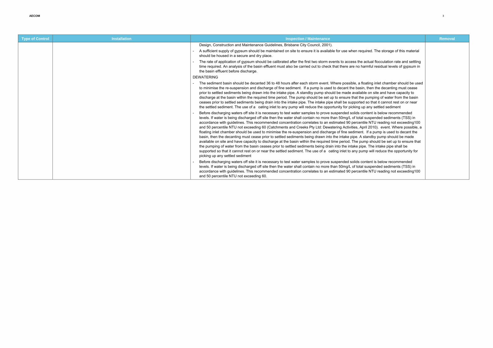
3
Type of Control Installation Inspection / Maintenance Removal Design, Construction and Maintenance Guidelines, Brisbane City Council, 2001).
- A sufficient supply of gypsum should be maintained on site to ensure it is available for use when required. The storage of this material should be housed in a secure and dry place.
- The rate of application of gypsum should be calibrated after the first two storm events to access the actual flocculation rate and settling time required. An analysis of the basin effluent must also be carried out to check that there are no harmful residual levels of gypsum in the basin effluent before discharge.
DEWATERING - The sediment basin should be decanted 36 to 48 hours after each storm event. Where possible, a floating inlet chamber should be used
to minimise the re-suspension and discharge of fine sediment. If a pump is used to decant the basin, then the decanting must cease prior to settled sediments being drawn into the intake pipe. A standby pump should be made available on site and have capacity to discharge at the basin within the required time period. The pump should be set up to ensure that the pumping of water from the basin ceases prior to settled sediments being drain into the intake pipe. The intake pipe shall be supported so that it cannot rest on or near the settled sediment. The use of a oating inlet to any pump will reduce the opportunity for picking up any settled sediment
- Before discharging waters off site it is necessary to test water samples to prove suspended solids content is below recommended levels. If water is being discharged off site then the water shall contain no more than 50mg/L of total suspended sediments (TSS) in accordance with guidelines. This recommended concentration correlates to an estimated 90 percentile NTU reading not exceeding100 and 50 percentile NTU not exceeding 60 (Catchments and Creeks Pty Ltd: Dewatering Activities, April 2010). event. Where possible, a floating inlet chamber should be used to minimise the re-suspension and discharge of fine sediment. If a pump is used to decant the basin, then the decanting must cease prior to settled sediments being drawn into the intake pipe. A standby pump should be made available on site and have capacity to discharge at the basin within the required time period. The pump should be set up to ensure that the pumping of water from the basin ceases prior to settled sediments being drain into the intake pipe. The intake pipe shall be supported so that it cannot rest on or near the settled sediment. The use of a oating inlet to any pump will reduce the opportunity for picking up any settled sediment
- Before discharging waters off site it is necessary to test water samples to prove suspended solids content is below recommended levels. If water is being discharged off site then the water shall contain no more than 50mg/L of total suspended sediments (TSS) in accordance with guidelines. This recommended concentration correlates to an estimated 90 percentile NTU reading not exceeding100 and 50 percentile NTU not exceeding 60.