constructing pure digital secondary moiré patterns
TRANSCRIPT
Constructing Pure Digital Secondary Moir6 Patterns
by Qi-Feng Yu
ABSTRACT--A new method of constructing pure digital secondary moird patterns of equal-strain fringes is proposed in this paper. By this method, a pure secondary moird pattern, without trace of primary moird fringes, is obtained directly from common digital moird patterns regardless of how low or high the fringe density. The pure secondary moir4 patterns eliminate the backnoise of primary fringes and give the strain value at every point over the whole strain field. This tech- nique can significantly increase the measurement accuracy and the range of moir~ techniques.
Introduction
An in-plane moir~ pattern consists of a group of equal- displacement fringes. However, the strain information for deformed objects is of more interest. Usually, displace- ment fields are extracted from an original moir~ pattern and then the strain fields are obtained from the displace- ment field by differentiation. Mechanical differentiation was developed to interweave and form a secondary moir~ pattern which consists of a group of equal-strain fringes. ~.2 However, a significant limitation of the mechanical differentiation is that it requires high fringe density of the moir6 pattern. Thus, it is difficult to get a good secondary moir6 pattern from a common geometric moir6 pattern; usually a mixture pattern of primary and secondary moir6 fringes with low accuracy is obtained. In order to obtain a secondary moir6 pattern, moir6 interferometry with a grating density more than 1000 e /mm is often used to get high density fringesP
The mechanical differentiation or the similar ones have been realized by digital-image-processing techniques. ' , ' Because these procedures themselves are still a version of mechanical differentiation, the main problems of mechanical differentiation remain unsolved. (1) They cannot eliminate the backnoise of the primary fringes which are very visible in their resultant patterns. (2) The fringe center lines of the resultant patterns, the strain corttours which are usually very sparse, are the only
Qi-Feng Yu is Associate Professor, Department o f Astronautics, Changsha Institute o f Technology, Changsha 410073, Hunan, People's Republic o f China. Paper was presented at the 1988 Spring Conference on Experimental Mechanics held in Portland, OR on June 5-10. Original manuscript submitted: April 22, 1988. Final manuscript received: January 31, 1990.
information that can be used. (3)The methods are not efficient when the primary fringes are not dense.
In this paper, constructing pure digital secondary moir6 patterns with the help of digital-image-processing techniques is proposed by utilizing fully the displacement information implied in the grey levels of the moir6 pattern. This method solves all the problems mentioned above. By this method, a pure secondary moir~ pattern, with no backnoise of primary fringes, is obtained from geometric moir6, or moir6 interferometry, regardless of the fringe density. The method not only gives the strain value at every point over the whole strain field but also increases the strain accuracy. Finally, to illustrate the procedure, some examples are given.
Basis and Preprocessing of Digital Moir~ Images
The bright and dark fringes in in-plane moir6 images represent the contour map of in-plane displacement in deformed specimens. After considering the nonlinear effect of the image system, the relationship between the grey levels of the digital moir~ pattern and the displacement of the deformed specimen is represented by an equation of the form (fundamental harmonic) ~.7
I ( x , y ) = I o ( x , y ) + I~ ( x , y ) . cos [ 2 7 r U ( x , y ) / P ]
+ L(x, y) (1)
where
I (x , y) = grey level of the moir6 pattern I, (x, y) = variation amplitude of the fringe grey level I o ( x , y) = grey level of the image background /~(x, y) = grey level of noise U ( x , y) = displacement of specimen perpendicular to
the reference grating P = pitch of the reference grating
Equation (1) is the law of grey level with respect to displacement which is the basis of the method presented in this paper.
In order to give a high quality primary moir~ image and make the proposed method applicable, the last term
Exper imenta l Mechanics �9 247
of eq (1) must be eliminated and [ o ( x , y ) and L ( x , y ) should be made constant over the whole field. In our project, the noise, 1. (x , y) , is eliminated by a spin filter which can filter out noise but not distort the fringe feature for fringe patterns? A separate linear enhancing method which is similar to the half-fringe method 7 is then used to make lo(X, y ) and L (x, y ) constant.
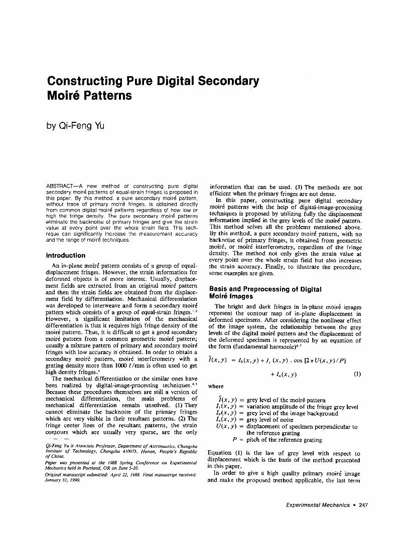
As shown in Fig. 1, the grey levels of a cross section of a moir~ pattern may be separated into several regions where both boundaries of each region are the neighboring top of the white fringe and bottom of the black fringe. In each region, there is a maximum grey level, Ira.., , and a minimum grey level, I , , .~ , which define the boundary points. The linear enhancing transformation below is performed in each separate region. In region i:
I ( x , y ) = B . [ ? ( x , y ) - I , . . , , . , ] l ( I = . , . - I . . , . , ) (2)
where I ( x , y ) . I ( x , y ) are, respectively, the grey levels before and after the transformation and B is the maximum grey level of the digital image system. (In our system. B = 255.) In each separated region, one has
L,.: , = Io(x,y) + L ( x , y )
I,,,,,, = l o ( x , y ) - I , ( x , y )
in region i. Substituting /mini, ImaXi and I ( x , y) of eq (1) into eq (2) yields
I ( x , y ) = B / 2 + B . cos [ 2 ~ r U ( x , y ) / P ] / 2
= /o +/~ �9 cos [ 2 r c U ( x , y ) / P ] O )
where Io = L = B I 2 = constant. Therefore, the linear enhancing transformation of eq (2) makes the top of the white fringe become B and the bottom of the black fringe become zero and the other grey levels become linearly transformed in between, in which the changes of the characteristics of original fringes can be neglected. Thus, a new moird pattern having constant fringe ampli tude/1 and background grey level, Io, in the whole field can be obtained by repeating the transformation of eq (2) for every separate region in the cross section as shown in
Fig. 1. Consequently, the grey level at every point in the n e w moir6 pattern of eq (3) implies directly certain dis- placement information about the specimen. Under the condition of eq (3), the moir~ pattern can be trans- formed into a pure secondary moir~ pattern as follows.
Construct ing Digital Secondary Moir6 Patterns First, the moir~ pattern of eq (3) is reconstructed
into a new moird pattern:
J ( x , y ) = /o+ /1 �9 sin [ 2 1 r U ( x , y ) l P ] (4)
Shifting the moird patterns of eq (3) and eq (4) in the x (or y) direction with a small equal increment Ax (or Ay) obtains two new patterns.
I ( x + A x , y ) = Io + I~ . cos [2~rU(x + A x , y ) / P ] =
h + I , �9 cos [ 2 r ( U ( x , y ) + A U ) / P ] (5)
J ( x + A x , y ) = Io + I~ . sin [ 2 w ( U ( x , y ) + A U ) / P ]
(6)
I ( x , y ) , [ (x , y)
/ : - I ! '1 I /
,,, >' II l \ t /
i i / / X 0 ini(d) .-
'Re [on i ' Reg/oll j ' Fig. 1--Gray-level scheme of a moir~ pattern in a cross section before and after the separate linear enhancing transformation
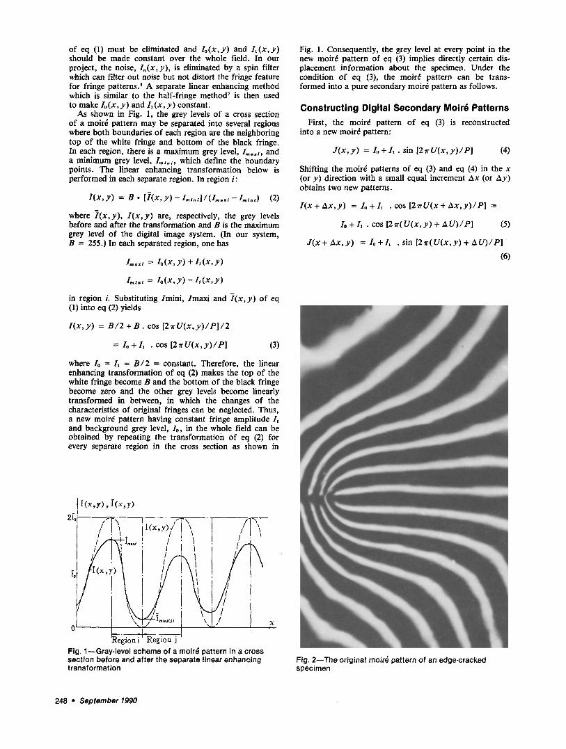
Fig. 2--The original moir4 pattern of an edge-cracked specimen
248 �9 September 1990
Doing arithmetic operations with the patterns of eqs (3), (5), (4) and (6) results in
M , = [ I ( x , y ) - Io1 �9 [ I ( x + , h x , y ) - Io1 =
It s [cos ( 2 7 r z ~ U / P ) + cos (21r(2U+ h U ) / P ) ] / 2
(7)
M2 = [ J ( x , y ) - h ] �9 [ J ( x + A x , y ) - lol =
I~ 2 [cos ( 2 ~ r A U / P ) - cos (2~r(2U + A U ) / P ) ] / 2
(8)
Adding eq (7) and eq (8), one obtains a digital pure secondary moir6 pattern M ( x , y):
M ( x , y ) = ( M I + M D / I o + Io = Io + I , . cos ( 2 7 r A U / P )
(9)
The physical meaning of the white fringes of eq (9) is analyzed as follows. Let
M ( x , y ) = Io +/~ = 2Io
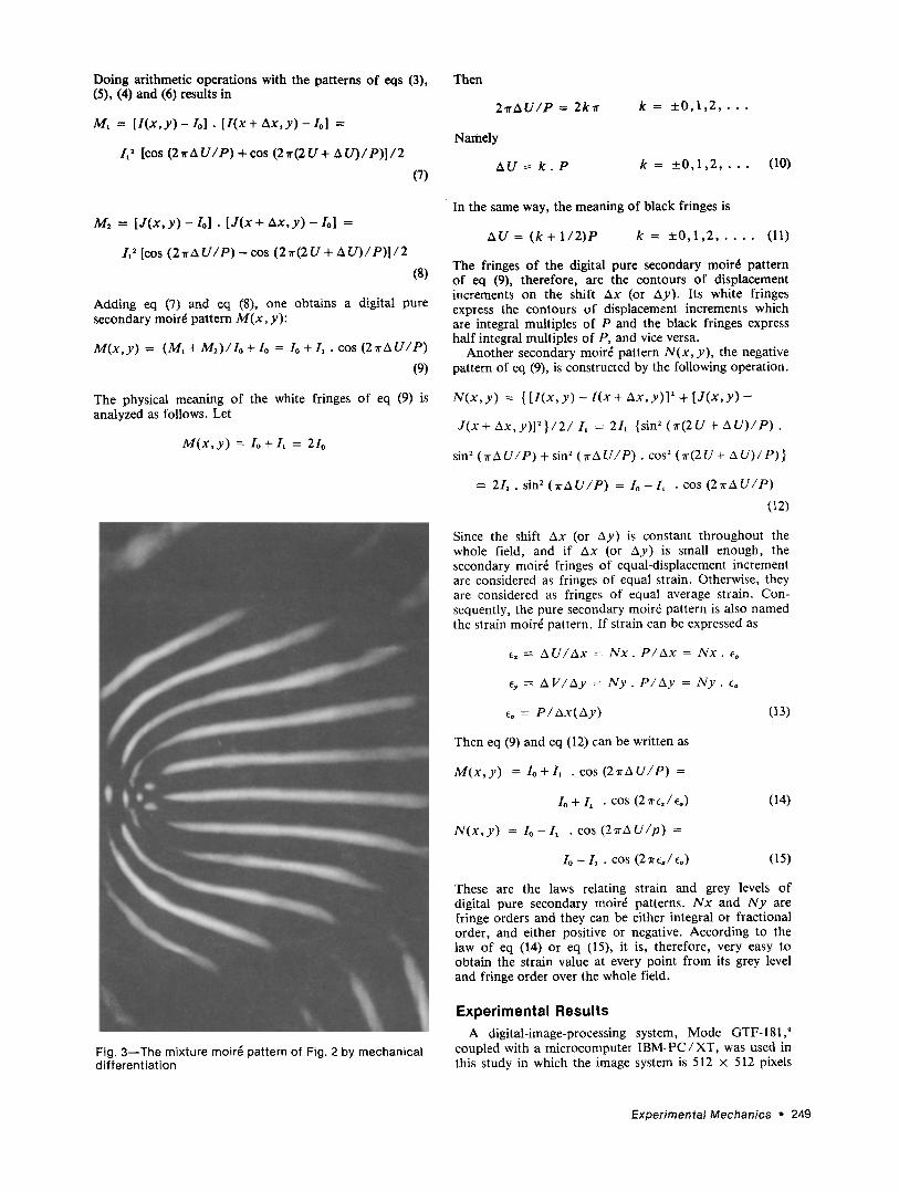
Fig. 3--The mixture moir~ pattern of Fig. 2 by mechanical differentiation
Then
2 ~ r A U / P = 2k'tr k = + _ 0 , 1 , 2 , . . .
N a m e l y
A U = k . P k = + _ 0 , 1 , 2 , . . . (10)
In the same way, the meaning of black fringes is
A U = ( k + l / 2 ) P k = +_0,1,2 . . . . . (11)
The fringes of the digital pure secondary moir~ pattern of eq (9), therefore, are the contours of displacement increments on the shift s (or Ay). Its white fringes express the contours of displacement increments which are integral multiples of P and the black fringes express half integral multiples of P, and vice versa.
Another secondary moir~ pattern N ( x , y ) , the negative pattern of eq (9), is constructed by the following operation.
N ( x , y ) = { [ I ( x , y ) - I ( x + A x , y ) ] 2 + [ J ( x , y ) -
J ( x + A x , y ) ] 2 } / 2 / /, = 2I, {sin ~ (Tr(2U + A U ) / P ) .
sin 2 ( r c A U / P ) + sin ~ O r A U / P ) . cos 2 (7r(2 U + 2 x U ) / P ) }
= 2/1 . sin 2 ( r A U / P ) = I o - L �9 cos ( 2 7 r A U / P )
(12)
Since the shift Ax (or Ay) is constant throughout the whole field, and if Ax (or Ay) is small enough, the secondary moir~ fringes of equal-displacement increment are considered as fringes of equal strain. Otherwise, they are considered as fringes of equal average strain. Con- sequently, the pure secondary moir6 pattern is also named the strain moir~ pattern. If strain can be expressed as
e~ = A U / A x = N x . P / A x = N x . e~
ey ---- A V / A y -- N y . P / A y = I V y . e,
eo = P / A x ( A y ) (i3)
Then eq (9) and eq (12) can be written as
M ( x , y ) = Io + I , . cos ( 2 ~ r A U / P ) =
/o + L �9 COS (27r~,/eo)
N ( x , y ) = I o - I ~ . cos ( 2 7 r A U / p ) =
I o - I, �9 cos (27r~/c0)
(14)
(15)
These are the laws relating strain and grey levels of digital pure secondary moir~ patterns. N x and IVy are fringe orders and they can be either integral or fractional order, and either positive or negative. According to the law of eq (14) or eq (15), it is, therefore, very easy to obtain the strain value at every point from its grey level and fringe order over the whole field.
Experimental Results A digital-image-processing system, Mode GTF-181, 9
coupled with a microcomputer IBM-PC/XT, was used in this study in which the image system is 512 x 512 pixels
Experimental Mechanics �9 249
with 256 grey levels. To give an example, a moir4 pattern of an edge-cracked specimen of polymer material with moir4 grating density of 20 e /mm was processed. The digital moird pattern was grabbed from the specimen directly. Figure 2 is the original moir6 pattern pre- processed by eq (2).
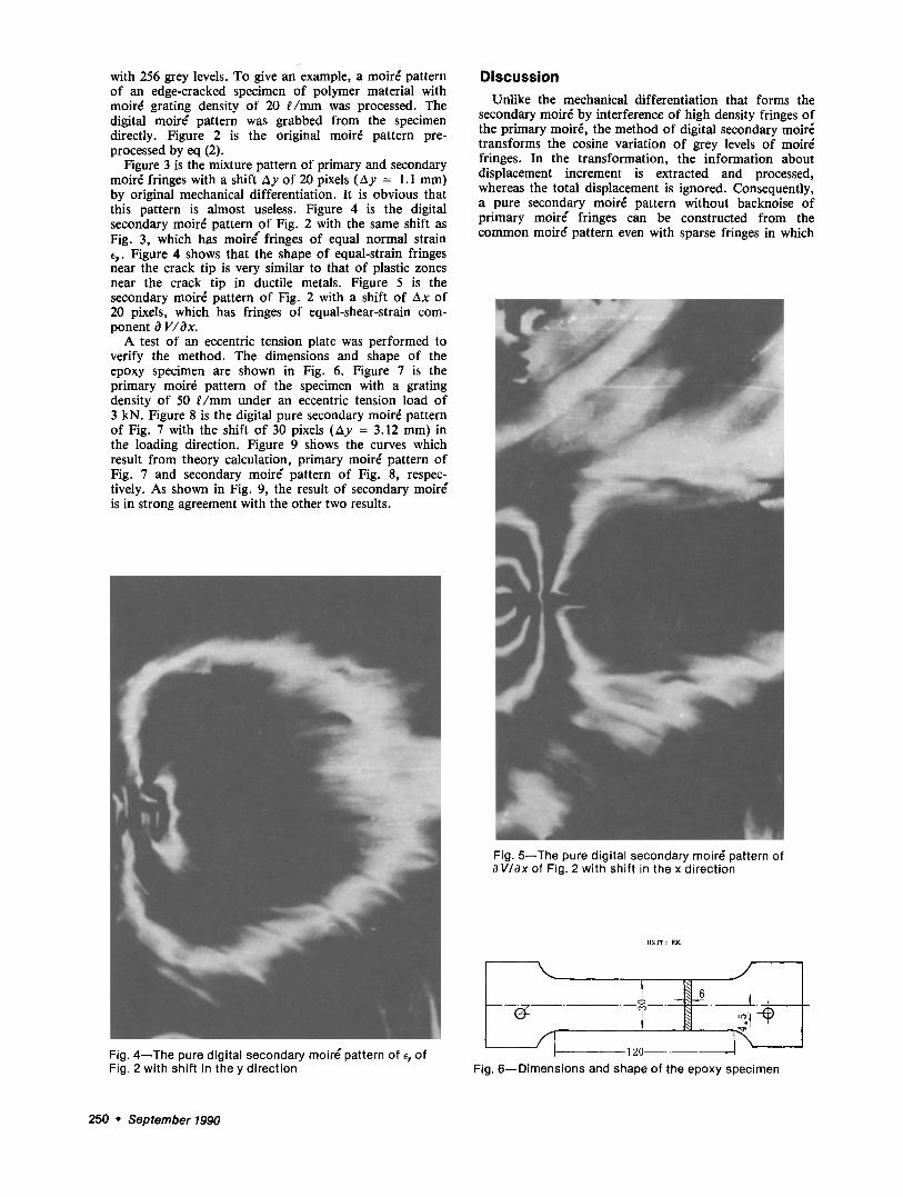
Figure 3 is the mixture pattern of primary and secondary moir4 fringes with a shift Ay of 20 pixels (Ay = 1.1 mm) by original mechanical differentiation. It is obvious that this pattern is almost useless. Figure 4 is the digital secondary moir4 pattern of Fig. 2 with the same shift as Fig. 3, which has moire" fringes of equal normal strain e,. Figure 4 shows that the shape of equal-strain fringes near the crack tip is very similar to that of plastic zones near the crack tip in ductile metals. Figure 5 is the secondary moir~ pattern of Fig. 2 with a shift of AX of 20 pixels, which has fringes of equal-shear-strain com- ponent O V/Ox.
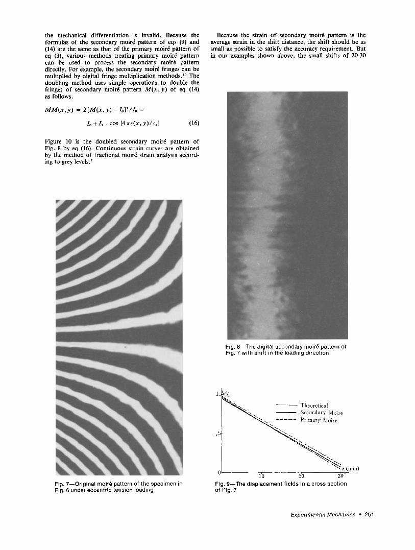
A test of an eccentric tension plate was performed to verify the method. The dimensions and shape of the epoxy specimen are shown in Fig, 6. Figure 7 is the primary moir6 pattern of the specimen with a grating density of 50 e /mm under an eccentric tension load of 3 kN. Figure 8 is the digital pure secondary moir4 pattern of Fig. 7 with the shift of 30 pixels (Ay = 3.12 mm) in the loading direction. Figure 9 shows the curves which result from theory calculation, primary moir~ pattern of Fig. 7 and secondary moire" pattern of Fig. 8, respec- tively. As shown in Fig. 9, the result of secondary moir( is in strong agreement with the other two results.
D i s c u s s i o n
Unlike the mechanical differentiation that forms the secondary moir4 by interference of high density fringes of the primary moire, the method of digital secondary moir6 transforms the cosine variation of grey levels of moir4 fringes. In the transformation, the information about displacement increment is extracted and processed, whereas the total displacement is ignored. Consequently, a pure secondary moir~ pattern without backnoise of primary moir4 fringes can be constructed from the common moir~ pattern even with sparse fringes in which
Fig. 5--The pure digital secondary moire; pattern of aWax of Fig. 2 with shift in the x direction
Fig. 4--The pure digital secondary moir6 pattern of ~y of Fig. 2 with shift in the y direction
UNiT :
1 2 0 - - ~- Fig. 6--Dimensions and shape of the epoxy specimen
250 �9 September 1990
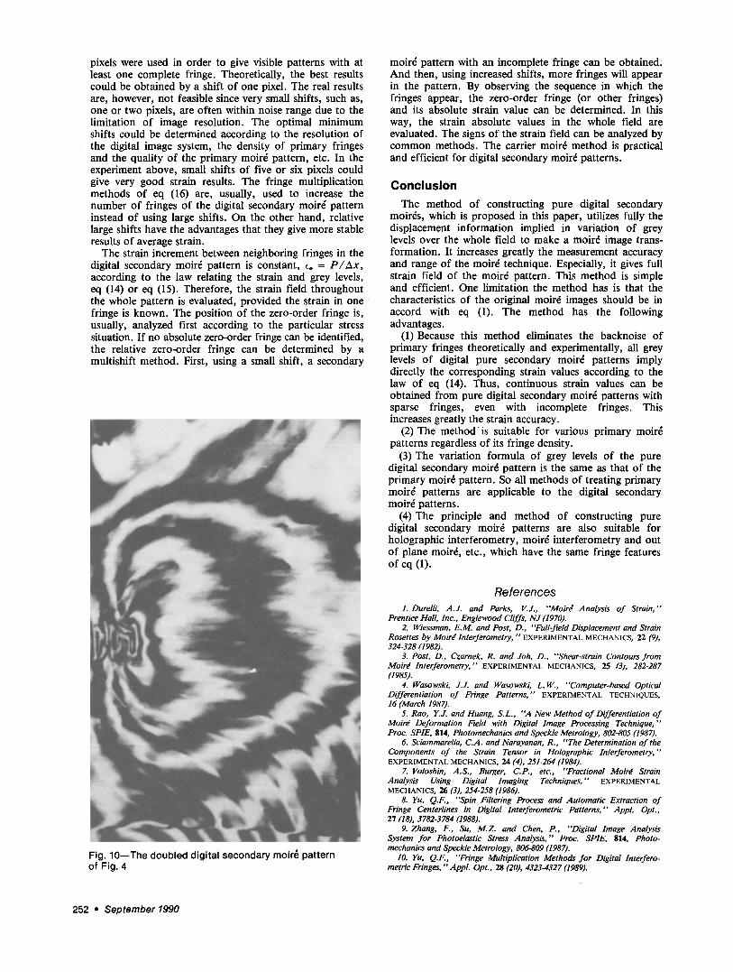
the mechanical differentiation is invalid. Because the formulas of the secondary moirg pattern of eqs (9) and (14) are the same as that of the primary moir~ pattern of eq (3), various methods treating primary moir~ pattern can be used to process the secondary moir~ pattern directly. For example, the secondary moir~ fringes can be multiplied by digital fringe multiplication methods? ~ The doubling method uses simple operations to double the fringes of secondary moir~ pattern M ( x , y ) of eq (14) as follows.
M M ( x , y) = 2 [M(x, y) - I o ] 2 / I o =
Io +/1 �9 cos [47re(x,y)/e.] (16)
Figure 10 is the doubled secondary moir~ pattern of Fig. 8 by eq (16). Continuous strain curves are obtained by the method of fractional moir6 strain analysis accord- ing to grey levels. 7
Because the strain of secondary moir6 pattern is the average strain in the shift distance, the shift should be as small as possible to satisfy the accuracy requirement. But in our examples shown above, the small shifts of 20-30
Fig. 8--The digital secondary moir~ pattern of Fig. 7 with shift in the loading direction
Fig. 7--Original moir~ pattern of the specimen in Fig. 6 under eccentric tension loading
.5
Theoretical x Secondary Moire
\ Primary Moire
x (mm) 1'0 - - 2~0 3~0 -
Fig. 9--The displacement fields in a cross section of Fig. 7
E x p e r i m e n t a l M e c h a n i c s ~ 251
pixels were used in order to give visible patterns with at least one complete fringe. Theoretically, the best results could be obtained by a shift of one pixel. The real results are, however, not feasible since very small shifts, such as, one or two pixels, are often within noise range due to the limitation of image resolution. The optimal minimum shifts could be determined according to the resolution of the digital image system, the density of primary fringes and the quality of the primary moir6 pattern, etc. In the experiment above, small shifts of five or six pixels could give very good strain results. The fringe multiplication methods of eq (16) are, usually, used to increase the number of fringes of the digital secondary moir~ pattern instead of using large shifts. On the other hand, relative large shifts have the advantages that they give more stable results of average strain.
The strain increment between neighboring fringes in the digital secondary moir~ pattern is constant, Co = P / A x ,
according to the law relating the strain and grey levels, eq (14) or eq (15). Therefore, the strain field throughout the whole pattern is evaluated, provided the strain in one fringe is known. The position of the zero-order fringe is, usually, analyzed first according to the particular stress situation. If no absolute zero-order fringe can be identified, the relative zero-order fringe can be determined by a multishift method. First, using a small shift, a secondary
Fig. 10--The doubled digital secondary moir6 pattern of Fig. 4
moir~ pattern with an incomplete fringe can be obtained. And then, using increased shifts, more fringes will appear in the pattern. By observing the sequence in which the fringes appear, the zero-order fringe (or other fringes) and its absolute strain value can be determined. In this way, the strain absolute values in the whole field are evaluated. The signs of the strain field can be analyzed by common methods. The carrier moir6 method is practical and efficient for digital secondary moir~ patterns.
Conclusion The method of constructing pure digital secondary
moires, which is proposed in this paper, utilizes fully the displacement information implied in variation of grey levels over the whole field to make a moire image trans- formation. It increases greatly the measurement accuracy and range of the moir~ technique. Especially, it gives full strain field of the moire pattern. This method is simple and efficient. One limitation the method has is that the characteristics of the original moir~ images should be in accord with eq (1). The method has the following advantages.
(1) Because this method eliminates the backnoise of primary fringes theoretically and experimentally, all grey levels of digital pure secondary moir~ patterns imply directly the corresponding strain values according to the law of eq (14). Thus, continuous strain values can be obtained from pure digital secondary moir~ patterns with sparse fringes, even with incomplete fringes. This increases greatly the strain accuracy.
(2) The method is suitable for various primary moir~ patterns regardless of its fringe density.
(3) The variation formula of grey levels of the pure digital secondary moir~ pattern is the same as that of the primary moir~ pattern. So all methods of treating primary moir~ patterns are applicable to the digital secondary moir~ patterns.
(4) The principle and method of constructing pure digital secondary moir~ patterns are also suitable for holographic interferometry, moir6 interferometry and out of plane moir6, etc., which have the same fringe features of eq (1).
References 1. Durelli, A.J. and Parks, V.J., "'Moir~ Analysis o f Strain,"
Prentice Hall, Inc., Englewood Cliffs, NJ (1970). 2. Wiessman, E.M. and Post, D., "'Full-field Displacement and Strain
Rosettes by Moird Interferometry, " EXPERIMENTAL MECHANICS, 22 (9), 324-328 (1982).
3. Post, D., Czarnek, R. and Joh, D., "'Shear-strain Contours from goird Interferometry, "" EXPERIMENTAL MECHANICS, 25 (3), 282-287 (1985).
4. Wasowski, J.J. and Wasowski, L.W., "'Computer-based Optical Differentiation of Fringe Patterns," EXPERIMENTAL TECHNIQUES, 16 (March 1987).
5. Rao, Y.J. and Huang, S.L., "'A New Method o f Differentiation of Moird Deformation Field with Digital Image Processing Technique, "" Proc. SPIE, 814, Photomechanics and Speckle Metrology, 802-805 (1987).
6. Sciammarella, C.A. and Narayanan, R., "'The Determination of the Components o f the Strain Tensor in Holographic Interferometry,'" EXPERIMENTAL MECHANICS, 24 (4), 251-264 (1984).
7. Voloshin, A.S., Burger, C.P., etc., "'Fractional Moird Strain Analysis Using Digital Imaging Techniques, "" EXPERIMENTAL MECHANICS, 26 (3), 254-2.58 (1986).
8. Yu, Q.F., "'Spin Filtering Process and Automatic Extraction of Fringe Centerlines in Digital Interferometric Patterns," Appl. Opt., 27 (18), 3782-3784 (1988).
9. Zhang, F,, Su, M.Z. and Chert, P., "'Digital Image Analysis System for Photoelastic Stress Analysis," Proc. SPIE, 814, Photo- mechanics and Speckle Metrology, 806-809 (1987).
10. Yu, Q.F., "'Fringe Multiplication Methods for Digital Interfero- metric Fringes, "" AppL Opt., 28 (20), 4323-4327 (1989).
252 �9 September 1990