configuring ctms administration software - cisco.com · to configure or edit access management...
TRANSCRIPT

Cisco TelePresence MOL-24273-01
C H A P T E R 3
Configuring CTMS Administration SoftwareMay 23, 2012
Contents• Overview, page 3-2
• Access Management, page 3-3
• Alert Management, page 3-6
• Configuration Files, page 3-8
• CTS-Manager, page 3-9
• Email Server, page 3-11
• Interface Failover, page 3-12
• Recording Server, page 3-13
• Security, page 3-14
• Services, page 3-14
• Software Upgrade, page 3-15
• System Settings, page 3-17
– IP, page 3-18
– NTP, page 3-19
– Route Pattern, page 3-20
– QoS, page 3-22
– Resources, page 3-25
– SNMP, page 3-26
– Call-in Timeout, page 3-31
– Restart CTMS, page 3-32
• Unified CM, page 3-32
– Unified CM, page 3-32
– SIP Profile Settings, page 3-34
• WebEx, page 3-36
3-1ultipoint Switch Release 1.9 Administration Guide
Chapter 3 Configuring CTMS Administration Software Overview
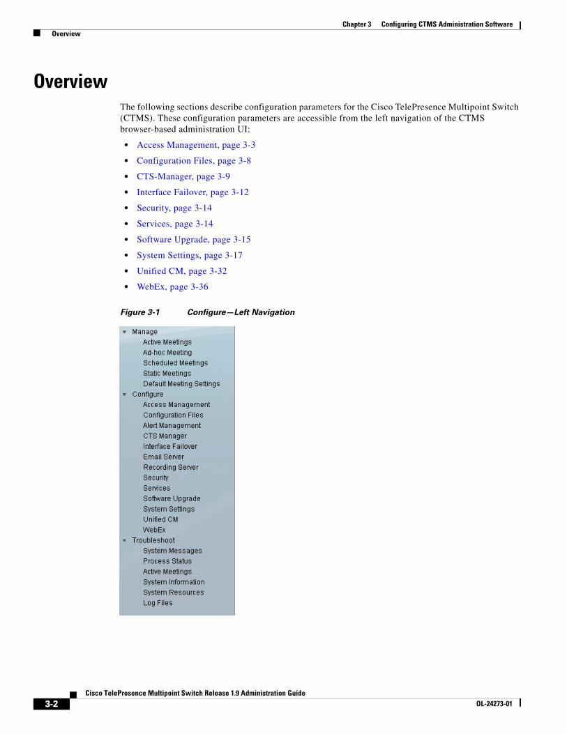
OverviewThe following sections describe configuration parameters for the Cisco TelePresence Multipoint Switch (CTMS). These configuration parameters are accessible from the left navigation of the CTMS browser-based administration UI:
• Access Management, page 3-3
• Configuration Files, page 3-8
• CTS-Manager, page 3-9
• Interface Failover, page 3-12
• Security, page 3-14
• Services, page 3-14
• Software Upgrade, page 3-15
• System Settings, page 3-17
• Unified CM, page 3-32
• WebEx, page 3-36
Figure 3-1 Configure—Left Navigation
3-2Cisco TelePresence Multipoint Switch Release 1.9 Administration Guide
OL-24273-01
Chapter 3 Configuring CTMS Administration Software Access Management
Access ManagementCTMS administration software recognizes three different administrative roles:
• Administrator: Administrators have the authority to perform all tasks associated with CTMS, including configuring settings; managing multipoint meetings; and maintaining, monitoring, and troubleshooting CTMS.
• Meeting Scheduler: Meeting Schedulers have the authority to perform multipoint meeting management tasks, such as defining meeting templates and setting up (and breaking down, as necessary) ad-hoc, static, and scheduled meetings.
• Diagnostic Technician: Diagnostic Technicians have the authority to perform CTMS monitoring and troubleshooting tasks.
Access to certain tasks and information is dependent on the administrative role. Administrative roles are considered a form of access management.
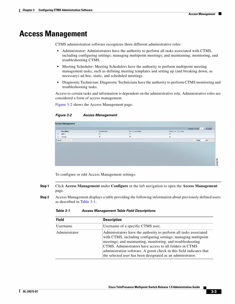
Figure 3-2 shows the Access Management page.
Figure 3-2 Access Management
To configure or edit Access Management settings:
Step 1 Click Access Management under Configure in the left navigation to open the Access Management page.
Step 2 Access Management displays a table providing the following information about previously defined users as described in Table 3-1.
Table 3-1 Access Management Table Field Descriptions
Field Description
Username Username of a specific CTMS user.
Administrator Administrators have the authority to perform all tasks associated with CTMS, including configuring settings; managing multipoint meetings; and maintaining, monitoring, and troubleshooting CTMS. Administrators have access to all folders in CTMS administration software. A green check in this field indicates that the selected user has been designated as an administrator.
3-3Cisco TelePresence Multipoint Switch Release 1.9 Administration Guide
OL-24273-01
Chapter 3 Configuring CTMS Administration Software Access Management
• To delete a user, click the radio button to the left of the entry. Then click Delete.
• To edit a user, click the radio button to the left of the entry. Then click Edit.
• To define a new user, click New,
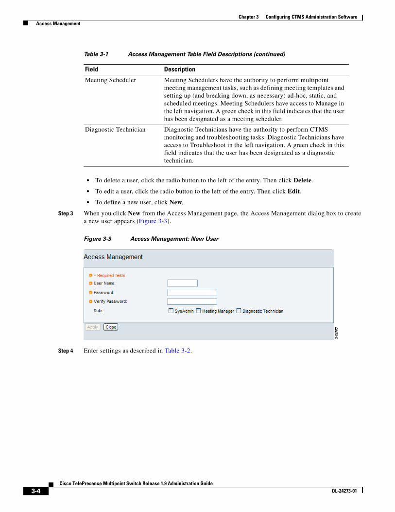
Step 3 When you click New from the Access Management page, the Access Management dialog box to create a new user appears (Figure 3-3).
Figure 3-3 Access Management: New User
Step 4 Enter settings as described in Table 3-2.
Meeting Scheduler Meeting Schedulers have the authority to perform multipoint meeting management tasks, such as defining meeting templates and setting up (and breaking down, as necessary) ad-hoc, static, and scheduled meetings. Meeting Schedulers have access to Manage in the left navigation. A green check in this field indicates that the user has been designated as a meeting scheduler.
Diagnostic Technician Diagnostic Technicians have the authority to perform CTMS monitoring and troubleshooting tasks. Diagnostic Technicians have access to Troubleshoot in the left navigation. A green check in this field indicates that the user has been designated as a diagnostic technician.
Table 3-1 Access Management Table Field Descriptions (continued)
Field Description
3-4Cisco TelePresence Multipoint Switch Release 1.9 Administration Guide
OL-24273-01
Chapter 3 Configuring CTMS Administration Software Access Management
• To register new or modified settings, click Apply.
• To close this window without applying settings, click Close.
Step 5 To edit an existing user profile, click the radio button to the left of the table entry to select the user. Then click Edit. When you click Edit, a dialog box appears.
Step 6 Enter settings as described in Table 3-3.
Table 3-2 New User Settings
Field or Button Setting
User Name Username of the new user.
Note A username must be at least 5 characters, but not more than 64 characters in length. The username must contain letters and numbers, but it cannot contain special characters, except for the underscore character. Letters can be uppercase and lowercase.
The username cannot be all numbers.
The following usernames are not allowed: apache, daemon, nobody, operator, and shutdown.
Password Password for the username indicated in the Username field.
Note Passwords must be at least 5 characters, but no more than 64 characters. Passwords must contain numbers and uppercase and lowercase letters. They can also contain special characters, such as the asterisk (*) or the hyphen (-).
Note When you change the Administrator role password for the first time after software installation, the new password cannot be similar to password that was configured during installation.
Verify Password Re-enter the password defined for this user.
Role Defines a specific user role. There are three possible roles, each with specific levels of administrative access:
• SysAdmin: Administrators have access to all pages and configuration tasks.
• Meeting Manager: Meeting managers have access only to the Manage pages and associated configuration tasks.
• Diagnostic Technician: Diagnostic technicians have access only to Troubleshoot pages and one task (system restart).
Note A single user can have more than one role.
Click the appropriate checkboxes to select.
3-5Cisco TelePresence Multipoint Switch Release 1.9 Administration Guide
OL-24273-01

Chapter 3 Configuring CTMS Administration Software Alert Management
• To register new settings, click Save.
• To close this window without applying settings, click Close.
Alert ManagementThe Alert Management page allows you to set the threshold that determines when CTMS sends email notifications that its hard disk is approaching or has exceeded the configured threshold or critical level.
Figure 3-4 shows the Alert Management page.
Figure 3-4 Alert Management
Table 3-3 Edit User Settings
Field or Button Setting
Username View only. Username of the CTMS user.
Current Password Current password for the CTMS user.
New Password New password for the CTMS user.
Note Passwords must be at least 5 characters, but no more than 64 characters. Passwords must contain numbers and uppercase and lowercase letters. They can also contain special characters, such as the asterisk (*) or the hyphen (-).
Note When you change the Administrator role password for the first time after software installation, the new password cannot be similar to password that was configured during installation.
Verify New Password Re-enter the password defined for this user.
3-6Cisco TelePresence Multipoint Switch Release 1.9 Administration Guide
OL-24273-01
Chapter 3 Configuring CTMS Administration Software Alert Management
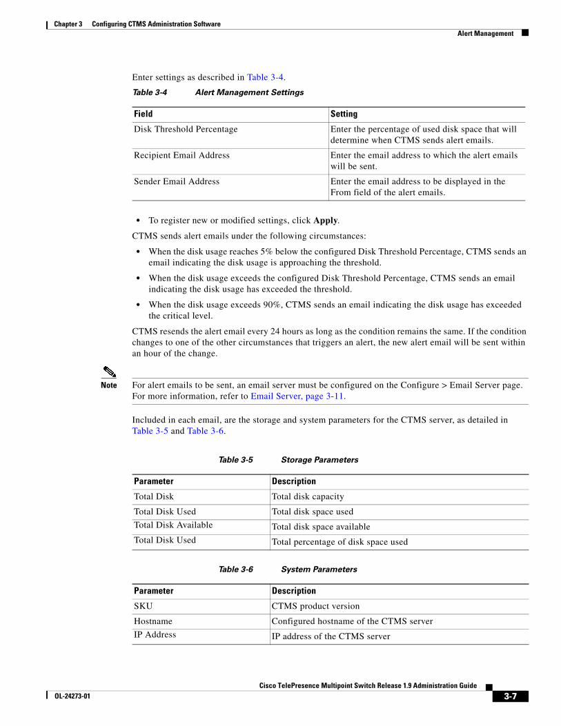
Enter settings as described in Table 3-4.
• To register new or modified settings, click Apply.
CTMS sends alert emails under the following circumstances:
• When the disk usage reaches 5% below the configured Disk Threshold Percentage, CTMS sends an email indicating the disk usage is approaching the threshold.
• When the disk usage exceeds the configured Disk Threshold Percentage, CTMS sends an email indicating the disk usage has exceeded the threshold.
• When the disk usage exceeds 90%, CTMS sends an email indicating the disk usage has exceeded the critical level.
CTMS resends the alert email every 24 hours as long as the condition remains the same. If the condition changes to one of the other circumstances that triggers an alert, the new alert email will be sent within an hour of the change.
Note For alert emails to be sent, an email server must be configured on the Configure > Email Server page. For more information, refer to Email Server, page 3-11.
Included in each email, are the storage and system parameters for the CTMS server, as detailed in Table 3-5 and Table 3-6.
Table 3-4 Alert Management Settings
Field Setting
Disk Threshold Percentage Enter the percentage of used disk space that will determine when CTMS sends alert emails.
Recipient Email Address Enter the email address to which the alert emails will be sent.
Sender Email Address Enter the email address to be displayed in the From field of the alert emails.
Table 3-5 Storage Parameters
Parameter Description
Total Disk Total disk capacity
Total Disk Used Total disk space used
Total Disk Available Total disk space available
Total Disk Used Total percentage of disk space used
Table 3-6 System Parameters
Parameter Description
SKU CTMS product version
Hostname Configured hostname of the CTMS server
IP Address IP address of the CTMS server
3-7Cisco TelePresence Multipoint Switch Release 1.9 Administration Guide
OL-24273-01
Chapter 3 Configuring CTMS Administration Software Configuration Files
Note The Disk Threshold Percentage setting is stored in the configuration files for CTMS.
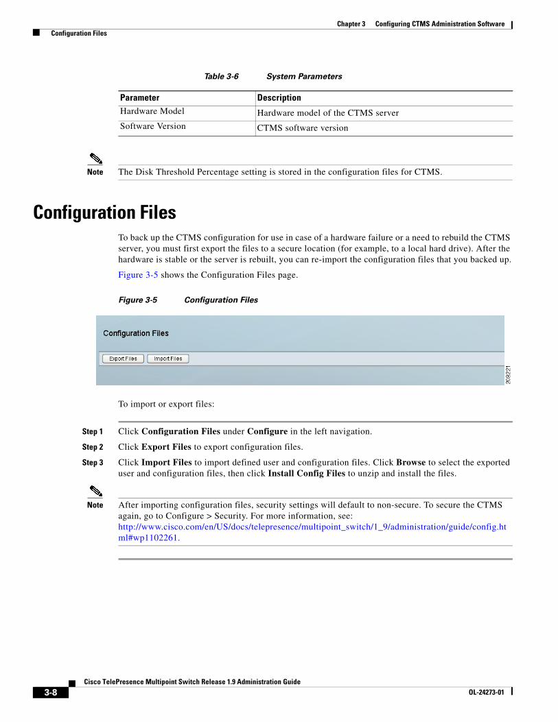
Configuration FilesTo back up the CTMS configuration for use in case of a hardware failure or a need to rebuild the CTMS server, you must first export the files to a secure location (for example, to a local hard drive). After the hardware is stable or the server is rebuilt, you can re-import the configuration files that you backed up.
Figure 3-5 shows the Configuration Files page.
Figure 3-5 Configuration Files
To import or export files:
Step 1 Click Configuration Files under Configure in the left navigation.
Step 2 Click Export Files to export configuration files.
Step 3 Click Import Files to import defined user and configuration files. Click Browse to select the exported user and configuration files, then click Install Config Files to unzip and install the files.
Note After importing configuration files, security settings will default to non-secure. To secure the CTMS again, go to Configure > Security. For more information, see: http://www.cisco.com/en/US/docs/telepresence/multipoint_switch/1_9/administration/guide/config.html#wp1102261.
Hardware Model Hardware model of the CTMS server
Software Version CTMS software version
Table 3-6 System Parameters
Parameter Description
3-8Cisco TelePresence Multipoint Switch Release 1.9 Administration Guide
OL-24273-01

Chapter 3 Configuring CTMS Administration Software CTS-Manager
CTS-ManagerThe Cisco TelePresence Manager (CTS-Man) manages CTMS resources for scheduled meetings. This section describes the settings that are necessary to build the communication channel between CTMS and CTS-Man. This section also includes information that CTS-Man needs to provide to the scheduled CTS endpoints.
Figure 3-6 shows the CTS-Manager page.
Figure 3-6 CTS-Manager
To configure or edit CTS-Manager settings:
Step 1 Click CTS-Manager under Configure in the left navigation to open the CTS-Manager page.
Step 2 The page displays the Cisco TelePresence Manager settings.
Step 3 Enter or edit settings as described in Table 3-7.
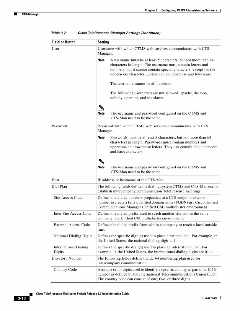
Table 3-7 Cisco TelePresence Manager Settings
Field or Button Setting
Description Text describing or identifying this particular CTMS. The maximum number of characters for this field is 62 characters.
Time Zone The time zone in which the CTMS is located. CTS-Man will use this setting to identify the closest CTMS for all scheduled CTS endpoints.
3-9Cisco TelePresence Multipoint Switch Release 1.9 Administration Guide
OL-24273-01
Chapter 3 Configuring CTMS Administration Software CTS-Manager
User Username with which CTMS web services communicates with CTS Manager.
Note A username must be at least 5 characters, but not more than 64 characters in length. The username must contain letters and numbers, but it cannot contain special characters, except for the underscore character. Letters can be uppercase and lowercase.
The username cannot be all numbers.
The following usernames are not allowed: apache, daemon, nobody, operator, and shutdown.
Note The username and password configured on the CTMS and CTS-Man need to be the same.
Password Password with which CTMS web services communicates with CTS Manager.
Note Passwords must be at least 5 characters, but not more than 64 characters in length. Passwords must contain numbers and uppercase and lowercase letters. They can contain the underscore and dash characters.
Note The username and password configured on the CTMS and CTS-Man need to be the same.
Host IP address or hostname of the CTS-Man.
Dial Plan The following fields define the dialing system CTMS and CTS-Man use to establish intercompany communication TelePresence meetings.
Site Access Code Defines the dialed numbers prepended to a CTS endpoint extension number to create a fully qualified domain name (FQDN) in a Cisco Unified Communications Manager (Unified CM) multicluster environment.
Inter Site Access Code Defines the dialed prefix used to reach another site within the same company in a Unified CM multicluster environment.
External Access Code Defines the dialed prefix from within a company to reach a local outside line.
National Dialing Digits Defines the specific digit(s) used to place a national call. For example, in the United States, the national dialing digit is 1.
International DialingDigits
Defines the specific digit(s) used to place an international call. For example, in the United States, the international dialing digits are 011.
Directory Number The following fields define the E.164 numbering plan used for intercompany communication.
Country Code A unique set of digits used to identify a specific country as part of an E.164 number as defined by the International Telecommunications Union (ITU). The country code can consist of one, two, or three digits.
Table 3-7 Cisco TelePresence Manager Settings (continued)
Field or Button Setting
3-10Cisco TelePresence Multipoint Switch Release 1.9 Administration Guide
OL-24273-01
Chapter 3 Configuring CTMS Administration Software Email Server
• To register new or modified settings, click Apply.
• To restore the original settings, click Cancel.
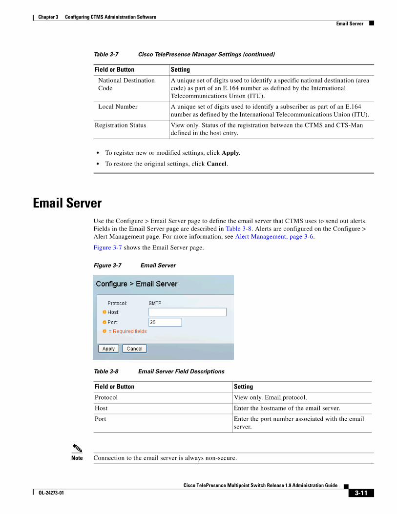
Email ServerUse the Configure > Email Server page to define the email server that CTMS uses to send out alerts. Fields in the Email Server page are described in Table 3-8. Alerts are configured on the Configure > Alert Management page. For more information, see Alert Management, page 3-6.
Figure 3-7 shows the Email Server page.
Figure 3-7 Email Server
Note Connection to the email server is always non-secure.
National DestinationCode
A unique set of digits used to identify a specific national destination (area code) as part of an E.164 number as defined by the International Telecommunications Union (ITU).
Local Number A unique set of digits used to identify a subscriber as part of an E.164 number as defined by the International Telecommunications Union (ITU).
Registration Status View only. Status of the registration between the CTMS and CTS-Man defined in the host entry.
Table 3-7 Cisco TelePresence Manager Settings (continued)
Field or Button Setting
Table 3-8 Email Server Field Descriptions
Field or Button Setting
Protocol View only. Email protocol.
Host Enter the hostname of the email server.
Port Enter the port number associated with the email server.
3-11Cisco TelePresence Multipoint Switch Release 1.9 Administration Guide
OL-24273-01
Chapter 3 Configuring CTMS Administration Software Interface Failover
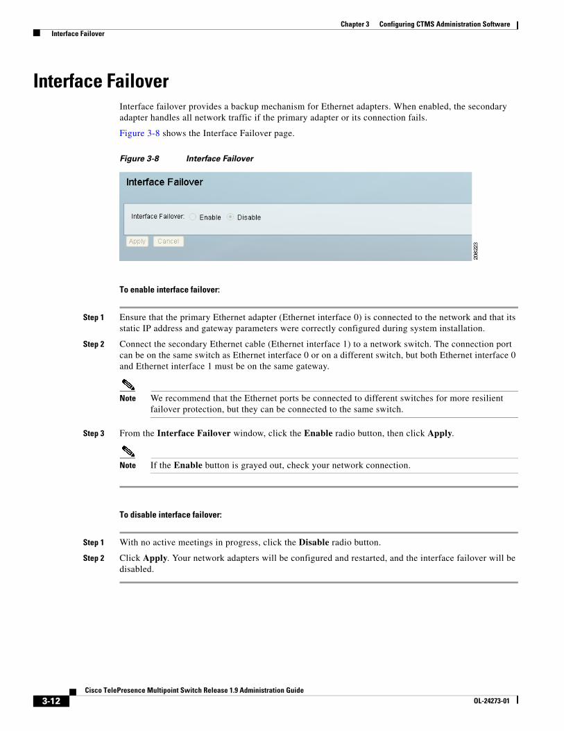
Interface FailoverInterface failover provides a backup mechanism for Ethernet adapters. When enabled, the secondary adapter handles all network traffic if the primary adapter or its connection fails.
Figure 3-8 shows the Interface Failover page.
Figure 3-8 Interface Failover
To enable interface failover:
Step 1 Ensure that the primary Ethernet adapter (Ethernet interface 0) is connected to the network and that its static IP address and gateway parameters were correctly configured during system installation.
Step 2 Connect the secondary Ethernet cable (Ethernet interface 1) to a network switch. The connection port can be on the same switch as Ethernet interface 0 or on a different switch, but both Ethernet interface 0 and Ethernet interface 1 must be on the same gateway.
Note We recommend that the Ethernet ports be connected to different switches for more resilient failover protection, but they can be connected to the same switch.
Step 3 From the Interface Failover window, click the Enable radio button, then click Apply.
Note If the Enable button is grayed out, check your network connection.
To disable interface failover:
Step 1 With no active meetings in progress, click the Disable radio button.
Step 2 Click Apply. Your network adapters will be configured and restarted, and the interface failover will be disabled.
3-12Cisco TelePresence Multipoint Switch Release 1.9 Administration Guide
OL-24273-01
Chapter 3 Configuring CTMS Administration Software Recording Server
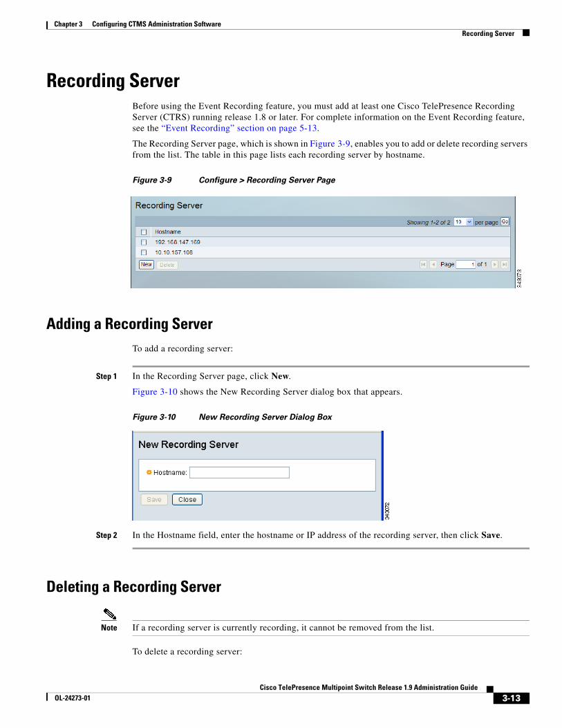
Recording ServerBefore using the Event Recording feature, you must add at least one Cisco TelePresence Recording Server (CTRS) running release 1.8 or later. For complete information on the Event Recording feature, see the “Event Recording” section on page 5-13.
The Recording Server page, which is shown in Figure 3-9, enables you to add or delete recording servers from the list. The table in this page lists each recording server by hostname.
Figure 3-9 Configure > Recording Server Page
Adding a Recording ServerTo add a recording server:
Step 1 In the Recording Server page, click New.
Figure 3-10 shows the New Recording Server dialog box that appears.
Figure 3-10 New Recording Server Dialog Box
Step 2 In the Hostname field, enter the hostname or IP address of the recording server, then click Save.
Deleting a Recording Server
Note If a recording server is currently recording, it cannot be removed from the list.
To delete a recording server:
3-13Cisco TelePresence Multipoint Switch Release 1.9 Administration Guide
OL-24273-01

Chapter 3 Configuring CTMS Administration Software Security
Step 1 In the Recording Server page, select one or more CTRS devices that you want to delete.
Step 2 Click Delete.
Step 3 To verify the deletion, click OK.
Security The CTMS supports these security types:
• Inter-device—Secures communication between Cisco TelePresence devices, which include the CTMS, Cisco TelePresence Manager (CTS-Manager), and Cisco TelePresence Recording Server (CTRS). In the case of the CTMS, securing communication between devices in turn enables you to determine the default security policy (secure or best effort) for multipoint meetings.
• Browser—Secures communication between the CTMS web server and the browser through which you access the CTMS Administrative UI. Browser security eliminates website security certificate warnings, which you receive if your web server is not secure.
You can set up either inter-device security or browser security on a CTMS, but not both at the same time.
For information on how to set up inter-device and browser security, see the Securing Cisco TelePresence Products, Release 1.8 and 1.9, which you can access at this location:
http://www.cisco.com/en/US/docs/telepresence/security_solutions/1_8/CTSS.html
Services CTMS uses Conference Control Protocol (CCP) to provide CTS endpoints with access to in-meeting functions, such as the participant list; room or speaker switching policies; and the lock meeting feature.
The participant list should include all endpoints, including audio add-ins. However, if an audio add-in is included through a CTS 1.6 or older endpoint, the audio add-in is not included in the participant list.
CCP is delivered over HTTP or HTTPS and can be forwarded to HTTP proxies in a secure enterprise domain where direct HTTP Internet access is not possible.
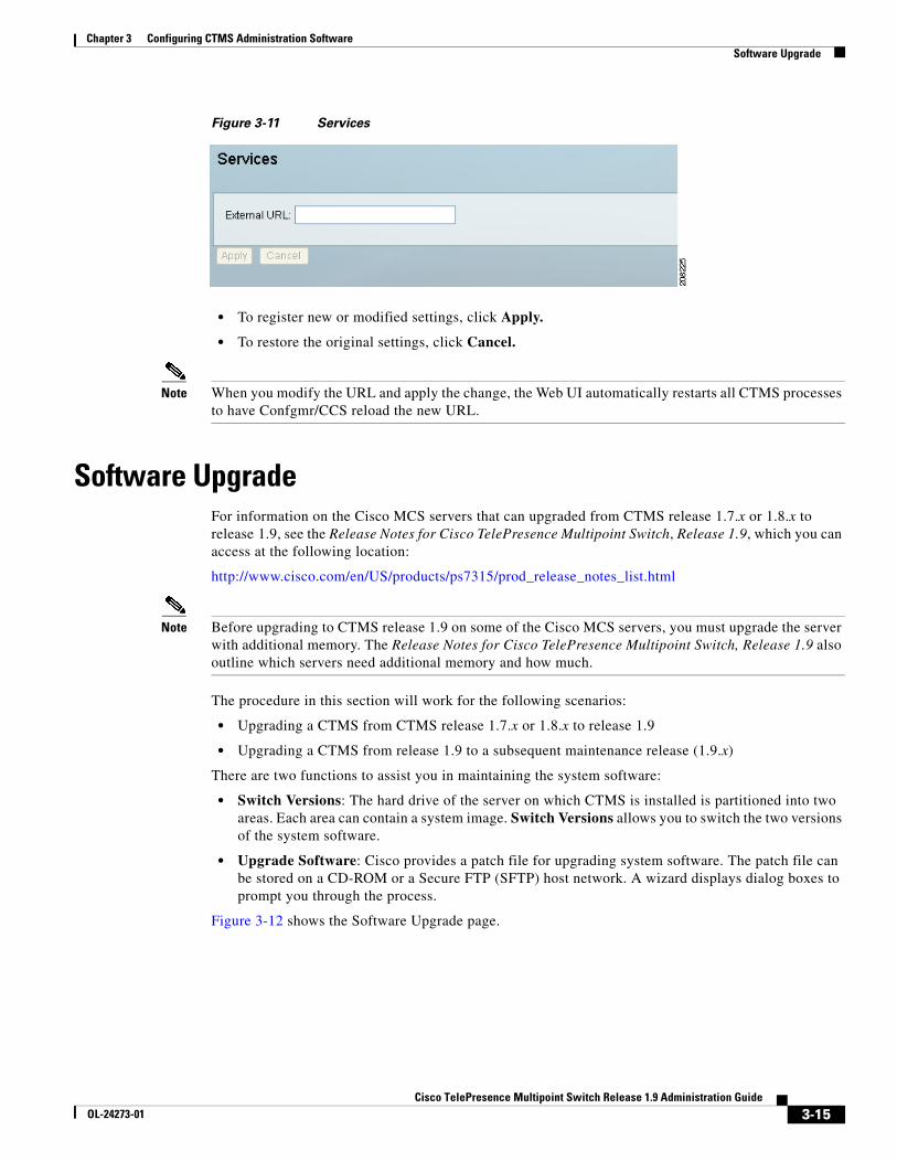
The Services section specifies the HTTP proxy URL that CTMS should advertise to the CTS endpoints in a multipoint meeting. Enterprises wishing to make InterCompany multipoint calls should work with their TelePresence provider to define the proxy requirement. If the URL is not specified, CTMS advertises its own default CCP URL. An incorrect URL stops in-meeting features from functioning but will not affect regular call setup and teardown.
3-14Cisco TelePresence Multipoint Switch Release 1.9 Administration Guide
OL-24273-01
Chapter 3 Configuring CTMS Administration Software Software Upgrade
Figure 3-11 Services
• To register new or modified settings, click Apply.
• To restore the original settings, click Cancel.
Note When you modify the URL and apply the change, the Web UI automatically restarts all CTMS processes to have Confgmr/CCS reload the new URL.
Software UpgradeFor information on the Cisco MCS servers that can upgraded from CTMS release 1.7.x or 1.8.x to release 1.9, see the Release Notes for Cisco TelePresence Multipoint Switch, Release 1.9, which you can access at the following location:
http://www.cisco.com/en/US/products/ps7315/prod_release_notes_list.html
Note Before upgrading to CTMS release 1.9 on some of the Cisco MCS servers, you must upgrade the server with additional memory. The Release Notes for Cisco TelePresence Multipoint Switch, Release 1.9 also outline which servers need additional memory and how much.
The procedure in this section will work for the following scenarios:
• Upgrading a CTMS from CTMS release 1.7.x or 1.8.x to release 1.9
• Upgrading a CTMS from release 1.9 to a subsequent maintenance release (1.9.x)
There are two functions to assist you in maintaining the system software:
• Switch Versions: The hard drive of the server on which CTMS is installed is partitioned into two areas. Each area can contain a system image. Switch Versions allows you to switch the two versions of the system software.
• Upgrade Software: Cisco provides a patch file for upgrading system software. The patch file can be stored on a CD-ROM or a Secure FTP (SFTP) host network. A wizard displays dialog boxes to prompt you through the process.
Figure 3-12 shows the Software Upgrade page.
3-15Cisco TelePresence Multipoint Switch Release 1.9 Administration Guide
OL-24273-01
Chapter 3 Configuring CTMS Administration Software Software Upgrade
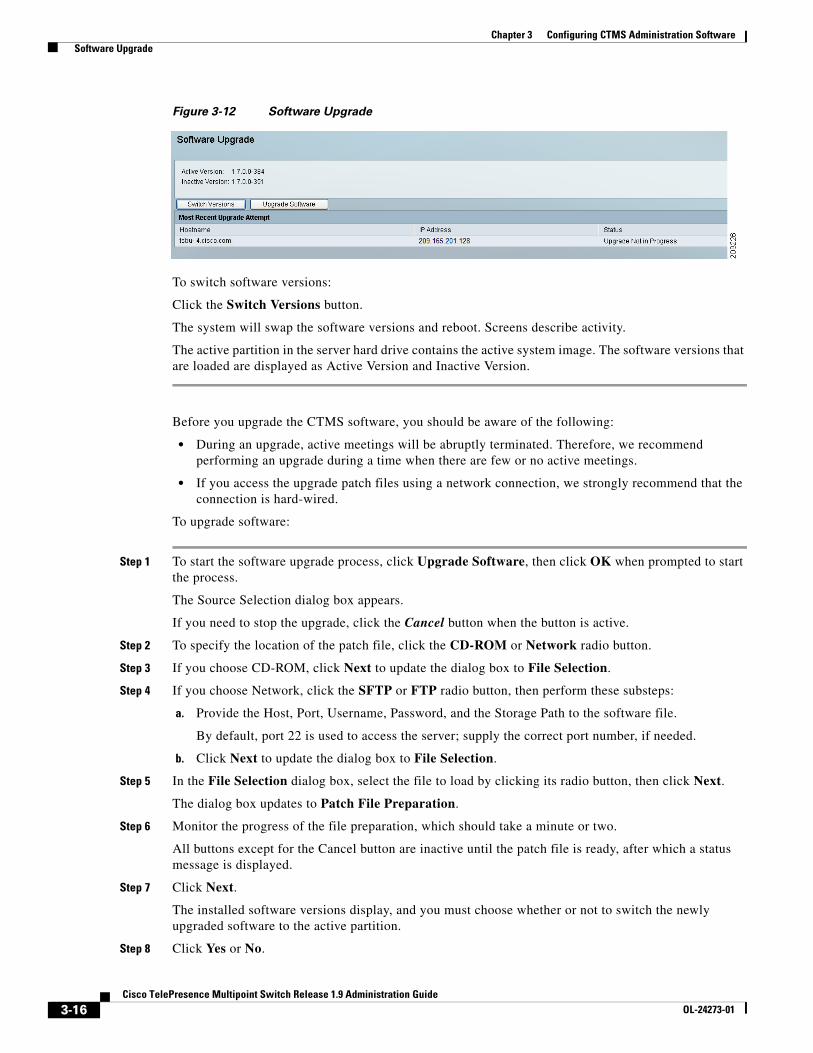
Figure 3-12 Software Upgrade
To switch software versions:
Click the Switch Versions button.
The system will swap the software versions and reboot. Screens describe activity.
The active partition in the server hard drive contains the active system image. The software versions that are loaded are displayed as Active Version and Inactive Version.
Before you upgrade the CTMS software, you should be aware of the following:
• During an upgrade, active meetings will be abruptly terminated. Therefore, we recommend performing an upgrade during a time when there are few or no active meetings.
• If you access the upgrade patch files using a network connection, we strongly recommend that the connection is hard-wired.
To upgrade software:
Step 1 To start the software upgrade process, click Upgrade Software, then click OK when prompted to start the process.
The Source Selection dialog box appears.
If you need to stop the upgrade, click the Cancel button when the button is active.
Step 2 To specify the location of the patch file, click the CD-ROM or Network radio button.
Step 3 If you choose CD-ROM, click Next to update the dialog box to File Selection.
Step 4 If you choose Network, click the SFTP or FTP radio button, then perform these substeps:
a. Provide the Host, Port, Username, Password, and the Storage Path to the software file.
By default, port 22 is used to access the server; supply the correct port number, if needed.
b. Click Next to update the dialog box to File Selection.
Step 5 In the File Selection dialog box, select the file to load by clicking its radio button, then click Next.
The dialog box updates to Patch File Preparation.
Step 6 Monitor the progress of the file preparation, which should take a minute or two.
All buttons except for the Cancel button are inactive until the patch file is ready, after which a status message is displayed.
Step 7 Click Next.
The installed software versions display, and you must choose whether or not to switch the newly upgraded software to the active partition.
Step 8 Click Yes or No.
3-16Cisco TelePresence Multipoint Switch Release 1.9 Administration Guide
OL-24273-01

Chapter 3 Configuring CTMS Administration Software System Settings
Step 9 Click Finish.
The Software Upgrade page reappears and displays the status of the upgrade and subsequent restart of the CTMS. The upgrade and restart can take several minutes.
The Continue button appears after the CTMS has restarted.
Step 10 To go to the CTMS Administrative UI login page, click Continue and log in if needed.
System SettingsSystem Settings are initially configured during CTMS administration software set up. Use System Settings to make changes to these initial settings:
• IP, page 3-18
• NTP, page 3-19
• Route Pattern, page 3-20
• QoS, page 3-22
• Resources, page 3-25
• SNMP, page 3-26
• Call-in Timeout, page 3-31
• Restart CTMS, page 3-32
3-17Cisco TelePresence Multipoint Switch Release 1.9 Administration Guide
OL-24273-01
Chapter 3 Configuring CTMS Administration Software System Settings
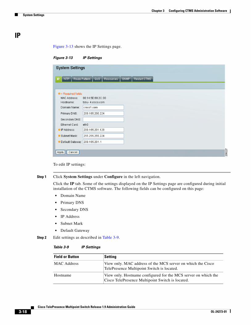
IPFigure 3-13 shows the IP Settings page.
Figure 3-13 IP Settings
To edit IP settings:
Step 1 Click System Settings under Configure in the left navigation.
Click the IP tab. Some of the settings displayed on the IP Settings page are configured during initial installation of the CTMS software. The following fields can be configured on this page:
• Domain Name
• Primary DNS
• Secondary DNS
• IP Address
• Subnet Mark
• Default Gateway
Step 2 Edit settings as described in Table 3-9.
Table 3-9 IP Settings
Field or Button Setting
MAC Address View only. MAC address of the MCS server on which the Cisco TelePresence Multipoint Switch is located.
Hostname View only. Hostname configured for the MCS server on which the Cisco TelePresence Multipoint Switch is located.
3-18Cisco TelePresence Multipoint Switch Release 1.9 Administration Guide
OL-24273-01

Chapter 3 Configuring CTMS Administration Software System Settings
• To register new or modified settings, click Apply.
• To restore the original settings, click Cancel.
NTPNetwork Time Protocol (NTP) servers allow CTMS to synchronize system time with CTS and CTS-Man. Synchronization is a critical component for scheduled meetings.
Caution NTP servers must be set up and functioning properly for CTMS to operate correctly.
Figure 3-14 shows the NTP Settings page.
Domain Name Domain name in which the MCS server on which the Cisco TelePresence Multipoint Switch is located.
Primary DNS IP address of the primary Domain Name System (DNS) server for the MCS server on which the Cisco TelePresence Multipoint Switch is located.
Secondary DNS IP address of the secondary Domain Name System (DNS) server for the MCS server on which the Cisco TelePresence Multipoint Switch is located.
Ethernet Card View only. Ethernet card being used on the MCU server to connect to the network.
IP Address IP address of the Cisco TelePresence Multipoint Switch.
Note After changing the IP address, close your browser window, then log into CTMS again using your new IP address.
Subnet Mask Subnet mask of the Cisco TelePresence Multipoint Switch.
Default Gateway Default gateway IP address for the Cisco TelePresence Multipoint Switch.
Table 3-9 IP Settings (continued)
Field or Button Setting
3-19Cisco TelePresence Multipoint Switch Release 1.9 Administration Guide
OL-24273-01

Chapter 3 Configuring CTMS Administration Software System Settings
Figure 3-14 NTP Settings
To edit NTP settings:
Step 1 Click System Settings under Configure in the left navigation.
Click the NTP tab to list the configured IP address of the NTP servers.
Step 2 Edit settings as described in Table 3-10.
• To register new or modified settings, click Apply.
• To restore the original settings, click Cancel.
Route PatternRoute pattern settings define route patterns—a string of digits that can be assigned to direct calls for specific devices and access numbers associated with this CTMS.
Note All of the settings in the Route Pattern page are derived from settings you previously configured in Cisco Unified Communications Manager (Cisco Unified CM).
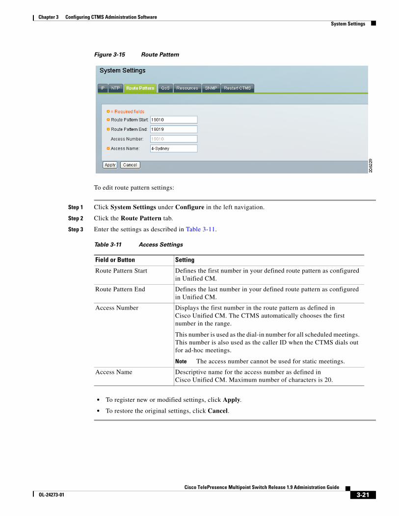
Figure 3-15 shows the Route Pattern page.
Table 3-10 NTP Settings
Field or Button Setting
NTP Server 1-5 IP address of the NTP server. To add an NTP server to the configuration, type the IP address in an NTP Server field. To change an NTP server in the configuration, highlight and delete the IP address in the NTP Server field and type in the new address.
Note You must configure at least two NTP servers.
3-20Cisco TelePresence Multipoint Switch Release 1.9 Administration Guide
OL-24273-01
Chapter 3 Configuring CTMS Administration Software System Settings
Figure 3-15 Route Pattern
To edit route pattern settings:
Step 1 Click System Settings under Configure in the left navigation.
Step 2 Click the Route Pattern tab.
Step 3 Enter the settings as described in Table 3-11.
• To register new or modified settings, click Apply.
• To restore the original settings, click Cancel.
Table 3-11 Access Settings
Field or Button Setting
Route Pattern Start Defines the first number in your defined route pattern as configured in Unified CM.
Route Pattern End Defines the last number in your defined route pattern as configured in Unified CM.
Access Number Displays the first number in the route pattern as defined in Cisco Unified CM. The CTMS automatically chooses the first number in the range.
This number is used as the dial-in number for all scheduled meetings. This number is also used as the caller ID when the CTMS dials out for ad-hoc meetings.
Note The access number cannot be used for static meetings.
Access Name Descriptive name for the access number as defined in Cisco Unified CM. Maximum number of characters is 20.
3-21Cisco TelePresence Multipoint Switch Release 1.9 Administration Guide
OL-24273-01
Chapter 3 Configuring CTMS Administration Software System Settings
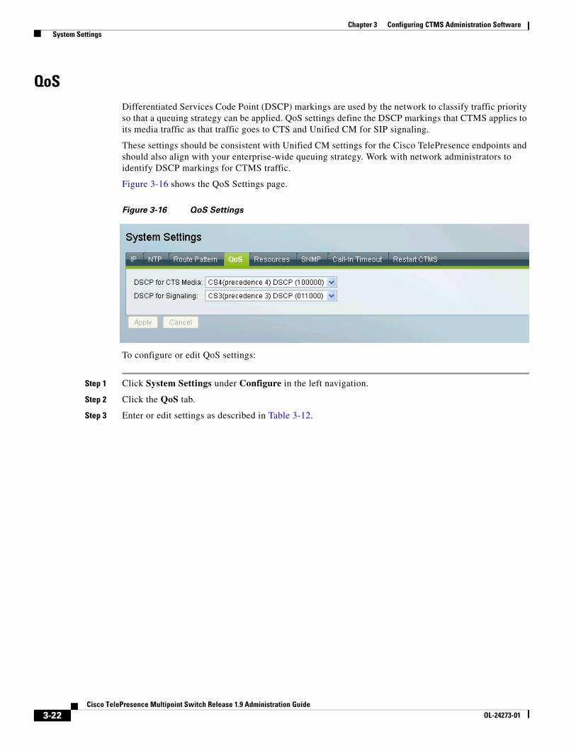
QoSDifferentiated Services Code Point (DSCP) markings are used by the network to classify traffic priority so that a queuing strategy can be applied. QoS settings define the DSCP markings that CTMS applies to its media traffic as that traffic goes to CTS and Unified CM for SIP signaling.
These settings should be consistent with Unified CM settings for the Cisco TelePresence endpoints and should also align with your enterprise-wide queuing strategy. Work with network administrators to identify DSCP markings for CTMS traffic.
Figure 3-16 shows the QoS Settings page.
Figure 3-16 QoS Settings
To configure or edit QoS settings:
Step 1 Click System Settings under Configure in the left navigation.
Step 2 Click the QoS tab.
Step 3 Enter or edit settings as described in Table 3-12.
3-22Cisco TelePresence Multipoint Switch Release 1.9 Administration Guide
OL-24273-01
Chapter 3 Configuring CTMS Administration Software System Settings
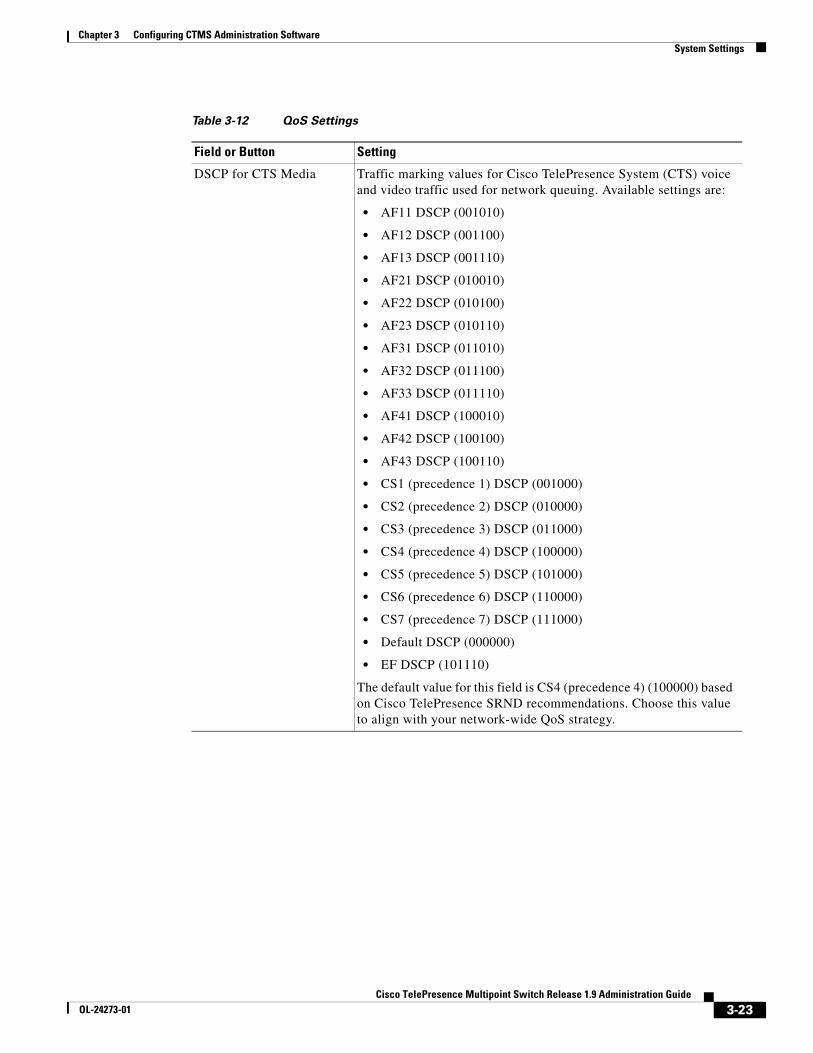
Table 3-12 QoS Settings
Field or Button Setting
DSCP for CTS Media Traffic marking values for Cisco TelePresence System (CTS) voice and video traffic used for network queuing. Available settings are:
• AF11 DSCP (001010)
• AF12 DSCP (001100)
• AF13 DSCP (001110)
• AF21 DSCP (010010)
• AF22 DSCP (010100)
• AF23 DSCP (010110)
• AF31 DSCP (011010)
• AF32 DSCP (011100)
• AF33 DSCP (011110)
• AF41 DSCP (100010)
• AF42 DSCP (100100)
• AF43 DSCP (100110)
• CS1 (precedence 1) DSCP (001000)
• CS2 (precedence 2) DSCP (010000)
• CS3 (precedence 3) DSCP (011000)
• CS4 (precedence 4) DSCP (100000)
• CS5 (precedence 5) DSCP (101000)
• CS6 (precedence 6) DSCP (110000)
• CS7 (precedence 7) DSCP (111000)
• Default DSCP (000000)
• EF DSCP (101110)
The default value for this field is CS4 (precedence 4) (100000) based on Cisco TelePresence SRND recommendations. Choose this value to align with your network-wide QoS strategy.
3-23Cisco TelePresence Multipoint Switch Release 1.9 Administration Guide
OL-24273-01
Chapter 3 Configuring CTMS Administration Software System Settings
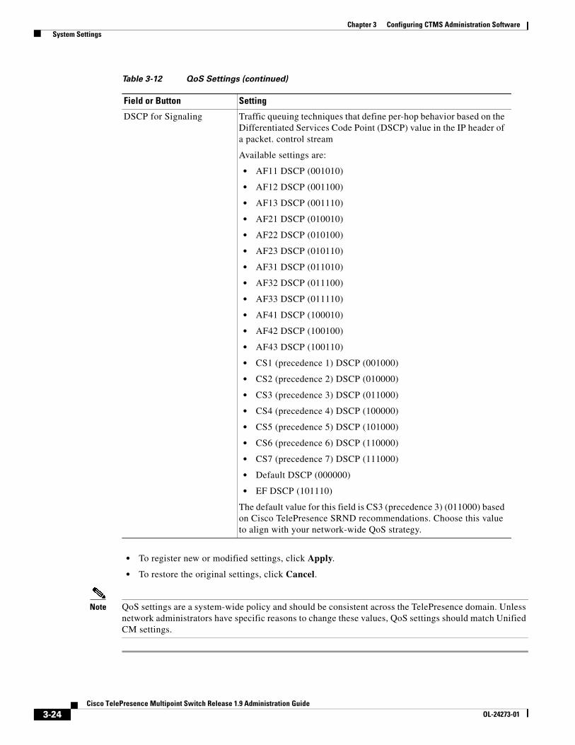
• To register new or modified settings, click Apply.
• To restore the original settings, click Cancel.
Note QoS settings are a system-wide policy and should be consistent across the TelePresence domain. Unless network administrators have specific reasons to change these values, QoS settings should match Unified CM settings.
DSCP for Signaling Traffic queuing techniques that define per-hop behavior based on the Differentiated Services Code Point (DSCP) value in the IP header of a packet. control stream
Available settings are:
• AF11 DSCP (001010)
• AF12 DSCP (001100)
• AF13 DSCP (001110)
• AF21 DSCP (010010)
• AF22 DSCP (010100)
• AF23 DSCP (010110)
• AF31 DSCP (011010)
• AF32 DSCP (011100)
• AF33 DSCP (011110)
• AF41 DSCP (100010)
• AF42 DSCP (100100)
• AF43 DSCP (100110)
• CS1 (precedence 1) DSCP (001000)
• CS2 (precedence 2) DSCP (010000)
• CS3 (precedence 3) DSCP (011000)
• CS4 (precedence 4) DSCP (100000)
• CS5 (precedence 5) DSCP (101000)
• CS6 (precedence 6) DSCP (110000)
• CS7 (precedence 7) DSCP (111000)
• Default DSCP (000000)
• EF DSCP (101110)
The default value for this field is CS3 (precedence 3) (011000) based on Cisco TelePresence SRND recommendations. Choose this value to align with your network-wide QoS strategy.
Table 3-12 QoS Settings (continued)
Field or Button Setting
3-24Cisco TelePresence Multipoint Switch Release 1.9 Administration Guide
OL-24273-01

Chapter 3 Configuring CTMS Administration Software System Settings
ResourcesResource Management settings enable you to specify the number of ad-hoc segments that can be scheduled for use.
Figure 3-17 shows the Resource Management page.
Figure 3-17 Resource Management
To configure or edit Resource Management settings:
Step 1 Click System Settings under Configure in the left navigation.
Step 2 Click the Resources tab.
Step 3 Enter or edit settings as described in Table 3-13.
3-25Cisco TelePresence Multipoint Switch Release 1.9 Administration Guide
OL-24273-01
Chapter 3 Configuring CTMS Administration Software System Settings
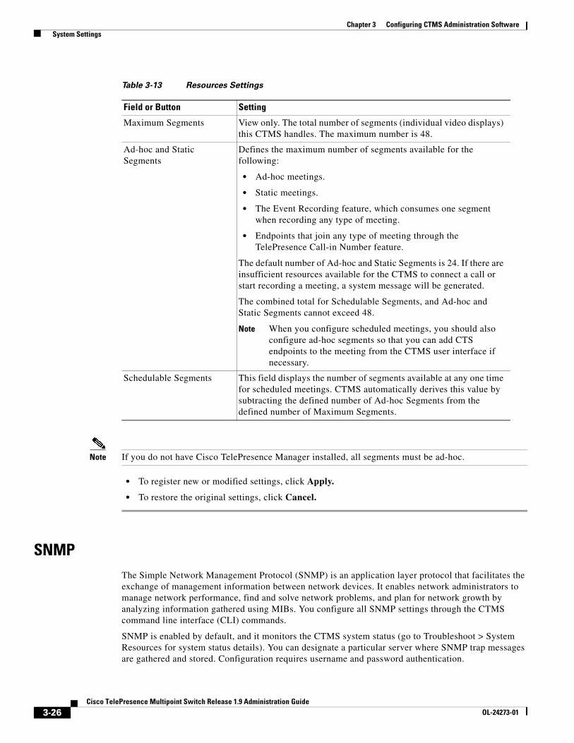
Note If you do not have Cisco TelePresence Manager installed, all segments must be ad-hoc.
• To register new or modified settings, click Apply.
• To restore the original settings, click Cancel.
SNMPThe Simple Network Management Protocol (SNMP) is an application layer protocol that facilitates the exchange of management information between network devices. It enables network administrators to manage network performance, find and solve network problems, and plan for network growth by analyzing information gathered using MIBs. You configure all SNMP settings through the CTMS command line interface (CLI) commands.
SNMP is enabled by default, and it monitors the CTMS system status (go to Troubleshoot > System Resources for system status details). You can designate a particular server where SNMP trap messages are gathered and stored. Configuration requires username and password authentication.
Table 3-13 Resources Settings
Field or Button Setting
Maximum Segments View only. The total number of segments (individual video displays) this CTMS handles. The maximum number is 48.
Ad-hoc and Static Segments
Defines the maximum number of segments available for the following:
• Ad-hoc meetings.
• Static meetings.
• The Event Recording feature, which consumes one segment when recording any type of meeting.
• Endpoints that join any type of meeting through the TelePresence Call-in Number feature.
The default number of Ad-hoc and Static Segments is 24. If there are insufficient resources available for the CTMS to connect a call or start recording a meeting, a system message will be generated.
The combined total for Schedulable Segments, and Ad-hoc and Static Segments cannot exceed 48.
Note When you configure scheduled meetings, you should also configure ad-hoc segments so that you can add CTS endpoints to the meeting from the CTMS user interface if necessary.
Schedulable Segments This field displays the number of segments available at any one time for scheduled meetings. CTMS automatically derives this value by subtracting the defined number of Ad-hoc Segments from the defined number of Maximum Segments.
3-26Cisco TelePresence Multipoint Switch Release 1.9 Administration Guide
OL-24273-01
Chapter 3 Configuring CTMS Administration Software System Settings
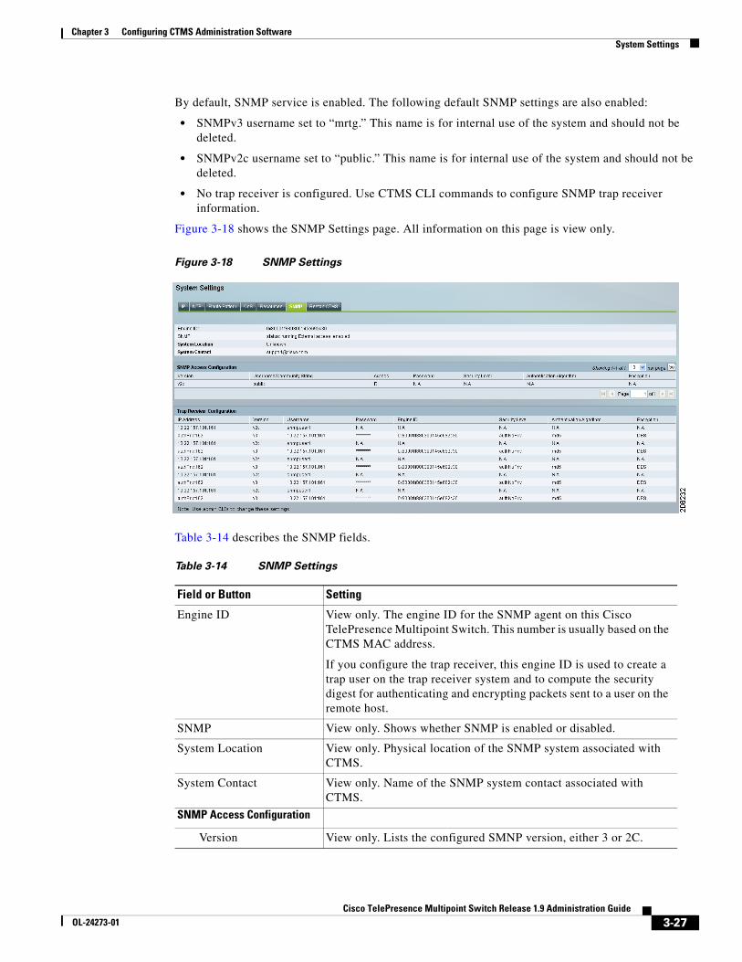
By default, SNMP service is enabled. The following default SNMP settings are also enabled:
• SNMPv3 username set to “mrtg.” This name is for internal use of the system and should not be deleted.
• SNMPv2c username set to “public.” This name is for internal use of the system and should not be deleted.
• No trap receiver is configured. Use CTMS CLI commands to configure SNMP trap receiver information.
Figure 3-18 shows the SNMP Settings page. All information on this page is view only.
Figure 3-18 SNMP Settings
Table 3-14 describes the SNMP fields.
Table 3-14 SNMP Settings
Field or Button Setting
Engine ID View only. The engine ID for the SNMP agent on this Cisco TelePresence Multipoint Switch. This number is usually based on the CTMS MAC address.
If you configure the trap receiver, this engine ID is used to create a trap user on the trap receiver system and to compute the security digest for authenticating and encrypting packets sent to a user on the remote host.
SNMP View only. Shows whether SNMP is enabled or disabled.
System Location View only. Physical location of the SNMP system associated with CTMS.
System Contact View only. Name of the SNMP system contact associated with CTMS.
SNMP Access Configuration
Version View only. Lists the configured SMNP version, either 3 or 2C.
3-27Cisco TelePresence Multipoint Switch Release 1.9 Administration Guide
OL-24273-01
Chapter 3 Configuring CTMS Administration Software System Settings
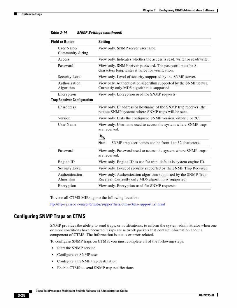
To view all CTMS MIBs, go to the following location:
ftp://ftp-sj.cisco.com/pub/mibs/supportlists/ctms/ctms-supportlist.html
Configuring SNMP Traps on CTMS
SNMP provides the ability to send traps, or notifications, to inform the system administrator when one or more conditions have occurred. Traps are network packets that contain information about a component of CTMS. The information is status or error-related.
To configure SNMP traps on CTMS, you must complete all of the following steps:
• Start the SNMP service
• Configure an SNMP user
• Configure an SNMP trap destination
• Enable CTMS to send SNMP trap notifications
User Name/ Community String
View only. SNMP server username.
Access View only. Indicates whether the access is read, writer or read/write.
Password View only. SNMP server password. The password must be 8 characters long. Enter it twice for verification.
Security Level View only. Level of security supported by the SNMP server.
Authorization Algorithm
View only. Authentication algorithm supported by the SNMP server. Currently only MD5 algorithm is supported.
Encryption View only. Encryption used for SNMP requests.
Trap Receiver Configuration
IP Address View only. IP address or hostname of the SNMP trap receiver (the remote SNMP system) where SNMP traps will be sent.
Version View only. Lists the configured SNMP version, either 3 or 2C.
User Name View only. Username used to access the system where SNMP traps are received.
Note SNMP trap user names can be from 1 to 32 characters.
Password View only. Password used to access the system where SNMP traps are received.
Engine ID View only. Engine ID to use for trap; default is system engine ID.
Security Level View only. Level of security supported by the SNMP Trap Receiver.
Authentication Algorithm
View only. Authentication algorithm supported by the SNMP Trap Receiver. Currently only MD5 algorithm is supported.
Encryption View only. Encryption used for SNMP requests.
Table 3-14 SNMP Settings (continued)
Field or Button Setting
3-28Cisco TelePresence Multipoint Switch Release 1.9 Administration Guide
OL-24273-01
Chapter 3 Configuring CTMS Administration Software System Settings
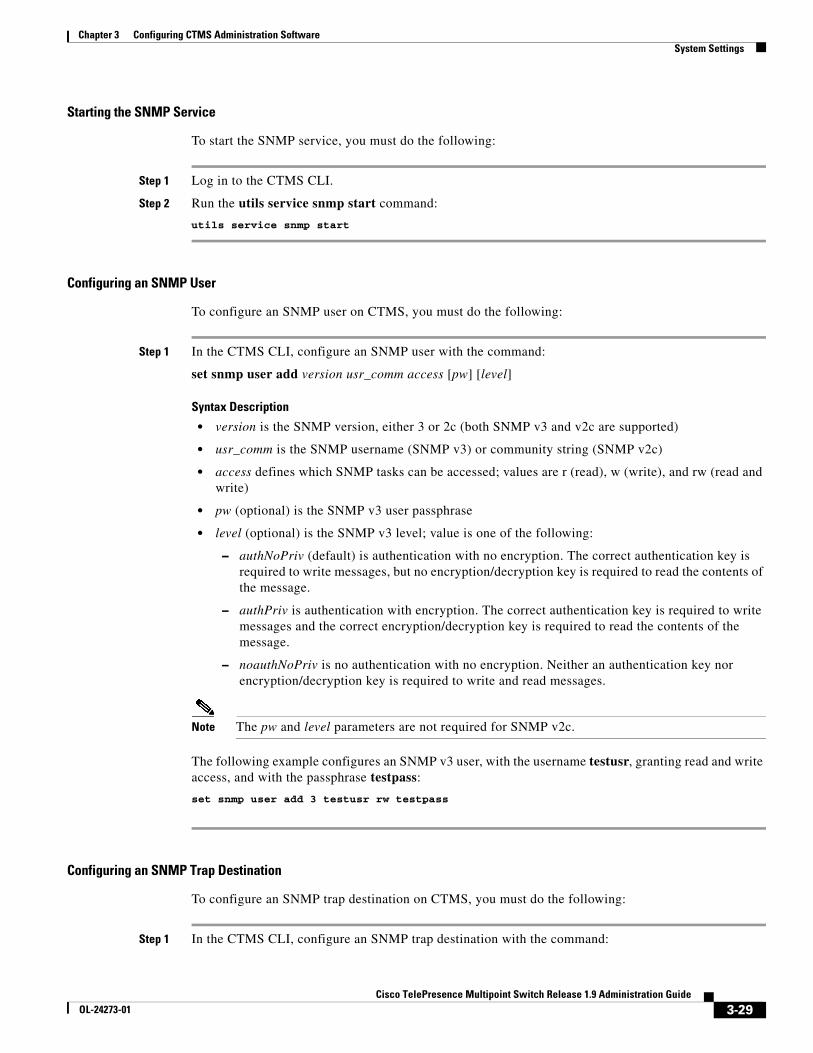
Starting the SNMP Service
To start the SNMP service, you must do the following:
Step 1 Log in to the CTMS CLI.
Step 2 Run the utils service snmp start command:
utils service snmp start
Configuring an SNMP User
To configure an SNMP user on CTMS, you must do the following:
Step 1 In the CTMS CLI, configure an SNMP user with the command:
set snmp user add version usr_comm access [pw] [level]
Syntax Description
• version is the SNMP version, either 3 or 2c (both SNMP v3 and v2c are supported)
• usr_comm is the SNMP username (SNMP v3) or community string (SNMP v2c)
• access defines which SNMP tasks can be accessed; values are r (read), w (write), and rw (read and write)
• pw (optional) is the SNMP v3 user passphrase
• level (optional) is the SNMP v3 level; value is one of the following:
– authNoPriv (default) is authentication with no encryption. The correct authentication key is required to write messages, but no encryption/decryption key is required to read the contents of the message.
– authPriv is authentication with encryption. The correct authentication key is required to write messages and the correct encryption/decryption key is required to read the contents of the message.
– noauthNoPriv is no authentication with no encryption. Neither an authentication key nor encryption/decryption key is required to write and read messages.
Note The pw and level parameters are not required for SNMP v2c.
The following example configures an SNMP v3 user, with the username testusr, granting read and write access, and with the passphrase testpass:
set snmp user add 3 testusr rw testpass
Configuring an SNMP Trap Destination
To configure an SNMP trap destination on CTMS, you must do the following:
Step 1 In the CTMS CLI, configure an SNMP trap destination with the command:
3-29Cisco TelePresence Multipoint Switch Release 1.9 Administration Guide
OL-24273-01
Chapter 3 Configuring CTMS Administration Software System Settings
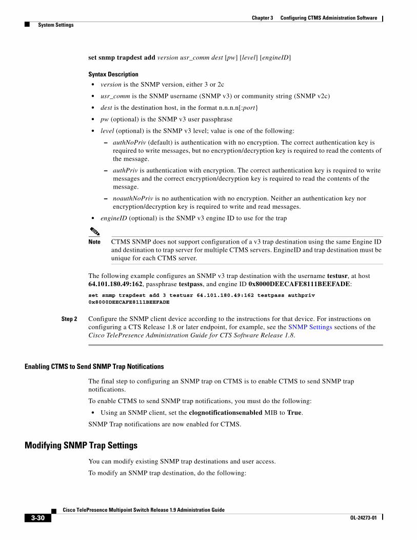
set snmp trapdest add version usr_comm dest [pw] [level] [engineID]
Syntax Description
• version is the SNMP version, either 3 or 2c
• usr_comm is the SNMP username (SNMP v3) or community string (SNMP v2c)
• dest is the destination host, in the format n.n.n.n[:port}
• pw (optional) is the SNMP v3 user passphrase
• level (optional) is the SNMP v3 level; value is one of the following:
– authNoPriv (default) is authentication with no encryption. The correct authentication key is required to write messages, but no encryption/decryption key is required to read the contents of the message.
– authPriv is authentication with encryption. The correct authentication key is required to write messages and the correct encryption/decryption key is required to read the contents of the message.
– noauthNoPriv is no authentication with no encryption. Neither an authentication key nor encryption/decryption key is required to write and read messages.
• engineID (optional) is the SNMP v3 engine ID to use for the trap
Note CTMS SNMP does not support configuration of a v3 trap destination using the same Engine ID and destination to trap server for multiple CTMS servers. EngineID and trap destination must be unique for each CTMS server.
The following example configures an SNMP v3 trap destination with the username testusr, at host 64.101.180.49:162, passphrase testpass, and engine ID 0x8000DEECAFE8111BEEFADE:
set snmp trapdest add 3 testusr 64.101.180.49:162 testpass authpriv 0x8000DEECAFE8111BEEFADE
Step 2 Configure the SNMP client device according to the instructions for that device. For instructions on configuring a CTS Release 1.8 or later endpoint, for example, see the SNMP Settings sections of the Cisco TelePresence Administration Guide for CTS Software Release 1.8.
Enabling CTMS to Send SNMP Trap Notifications
The final step to configuring an SNMP trap on CTMS is to enable CTMS to send SNMP trap notifications.
To enable CTMS to send SNMP trap notifications, you must do the following:
• Using an SNMP client, set the clognotificationsenabled MIB to True.
SNMP Trap notifications are now enabled for CTMS.
Modifying SNMP Trap Settings
You can modify existing SNMP trap destinations and user access.
To modify an SNMP trap destination, do the following:
3-30Cisco TelePresence Multipoint Switch Release 1.9 Administration Guide
OL-24273-01
Chapter 3 Configuring CTMS Administration Software System Settings
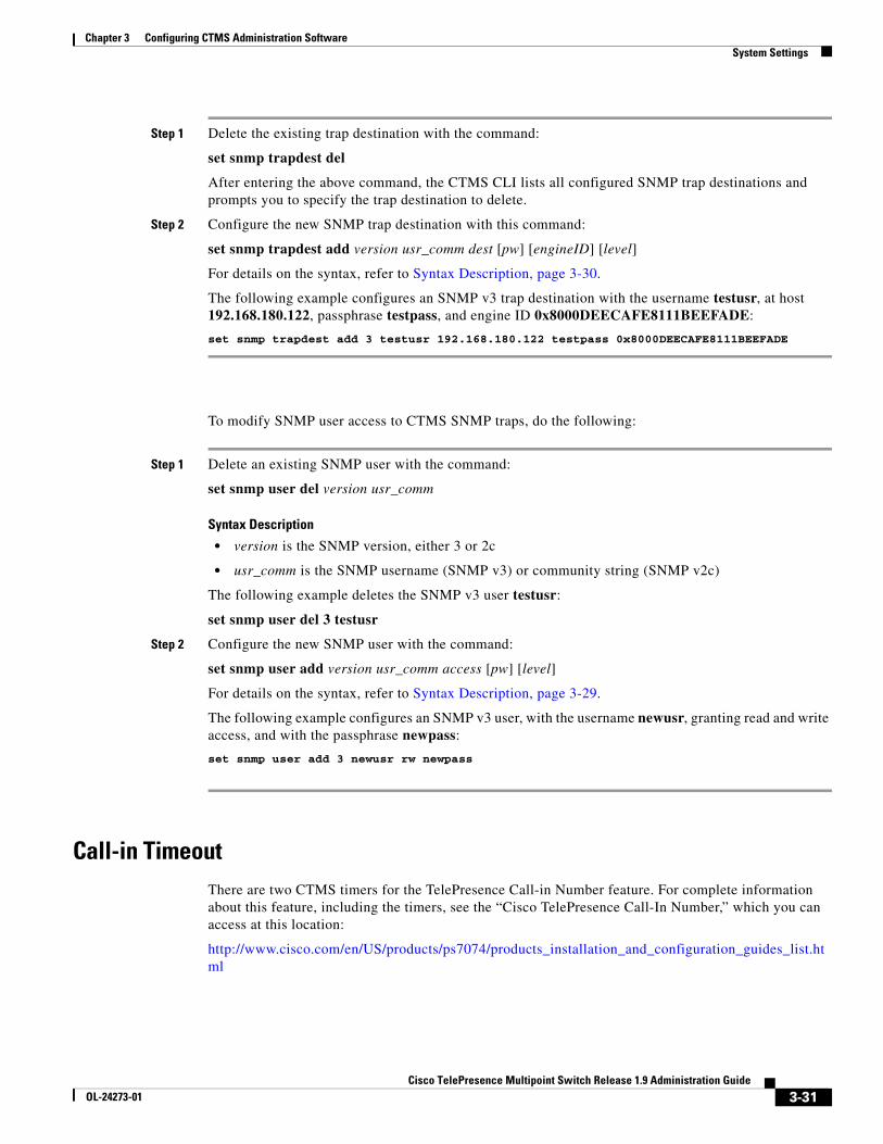
Step 1 Delete the existing trap destination with the command:
set snmp trapdest del
After entering the above command, the CTMS CLI lists all configured SNMP trap destinations and prompts you to specify the trap destination to delete.
Step 2 Configure the new SNMP trap destination with this command:
set snmp trapdest add version usr_comm dest [pw] [engineID] [level]
For details on the syntax, refer to Syntax Description, page 3-30.
The following example configures an SNMP v3 trap destination with the username testusr, at host 192.168.180.122, passphrase testpass, and engine ID 0x8000DEECAFE8111BEEFADE:
set snmp trapdest add 3 testusr 192.168.180.122 testpass 0x8000DEECAFE8111BEEFADE
To modify SNMP user access to CTMS SNMP traps, do the following:
Step 1 Delete an existing SNMP user with the command:
set snmp user del version usr_comm
Syntax Description
• version is the SNMP version, either 3 or 2c
• usr_comm is the SNMP username (SNMP v3) or community string (SNMP v2c)
The following example deletes the SNMP v3 user testusr:
set snmp user del 3 testusr
Step 2 Configure the new SNMP user with the command:
set snmp user add version usr_comm access [pw] [level]
For details on the syntax, refer to Syntax Description, page 3-29.
The following example configures an SNMP v3 user, with the username newusr, granting read and write access, and with the passphrase newpass:
set snmp user add 3 newusr rw newpass
Call-in TimeoutThere are two CTMS timers for the TelePresence Call-in Number feature. For complete information about this feature, including the timers, see the “Cisco TelePresence Call-In Number,” which you can access at this location:
http://www.cisco.com/en/US/products/ps7074/products_installation_and_configuration_guides_list.html
3-31Cisco TelePresence Multipoint Switch Release 1.9 Administration Guide
OL-24273-01

Chapter 3 Configuring CTMS Administration Software Unified CM
Restart CTMSFigure 3-19 shows the Restart CTMS page.
Figure 3-19 Restart CTMS
To restart CTMS or to shut down CTMS:
Step 1 Click System Settings under Configure in the left navigation.
Step 2 Click the Restart CTMS tab.
Step 3 Click Restart to restart—meaning shutdown and then reboot—CTMS.
Step 4 Click Shutdown to completely shutdown CTMS.
Unified CMThe following sections describe how to make changes to the Cisco Unified Communications Manager (Unified CM) settings:
• Unified CM, page 3-32
• SIP Profile Settings, page 3-34
Unified CMFigure 3-20 shows the Unified CM page.
3-32Cisco TelePresence Multipoint Switch Release 1.9 Administration Guide
OL-24273-01

Chapter 3 Configuring CTMS Administration Software Unified CM
Figure 3-20 Unified CM
To configure or edit Unified CM settings:
Step 1 Click Unified CM under Configure in the left navigation.
Step 2 Click the Unified CM Settings tab.
Step 3 Enter settings as described in Table 3-15.
• To register new or modified settings, click Apply.
• To restore the original settings, click Cancel.
Table 3-15 Unified CM Settings
Field or Button Setting
Unified CM 1 through 5 Hostnames or IP address(es) of the Unified CM server.
Note It is important to add all Unified CM servers in the cluster.
SIP Port Port number for Cisco Unified SIP IP Phones that are using UDP to listen for SIP messages from Unified CM. The default setting equals 5060.
3-33Cisco TelePresence Multipoint Switch Release 1.9 Administration Guide
OL-24273-01

Chapter 3 Configuring CTMS Administration Software Unified CM
SIP Profile SettingsFigure 3-21 shows the SIP Profile Settings page.
Figure 3-21 SIP Profile Settings
To configure or edit SIP Profile settings:
Step 1 Click Unified CM Settings under Configure in the left navigation.
Step 2 Click the SIP Profile Settings tab.
Step 3 Enter or edit settings as described in Table 3-16.
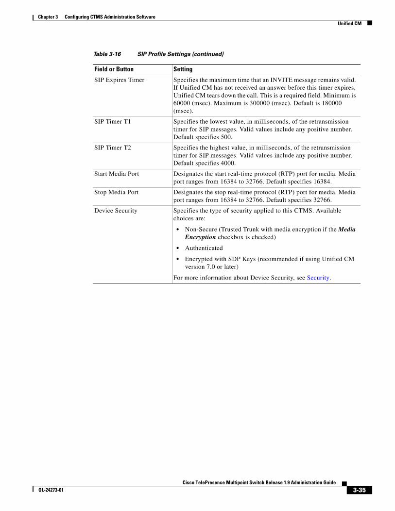
Table 3-16 SIP Profile Settings
Field or Button Setting
Retry Count for SIP Invite Specifies the number of times that Cisco Unified Communications Manager (Unified CM) will resend the INVITE message. This is a required field. Minimum is 1. Maximum is 10 Default is 6.
Retry Count for SIP non-Invite Request
Specifies the number of times that Unified CM will resend the non-INVITE message. This is a required field. Minimum is 1. Maximum is 10 Default is 6.
3-34Cisco TelePresence Multipoint Switch Release 1.9 Administration Guide
OL-24273-01
Chapter 3 Configuring CTMS Administration Software Unified CM
SIP Expires Timer Specifies the maximum time that an INVITE message remains valid. If Unified CM has not received an answer before this timer expires, Unified CM tears down the call. This is a required field. Minimum is 60000 (msec). Maximum is 300000 (msec). Default is 180000 (msec).
SIP Timer T1 Specifies the lowest value, in milliseconds, of the retransmission timer for SIP messages. Valid values include any positive number. Default specifies 500.
SIP Timer T2 Specifies the highest value, in milliseconds, of the retransmission timer for SIP messages. Valid values include any positive number. Default specifies 4000.
Start Media Port Designates the start real-time protocol (RTP) port for media. Media port ranges from 16384 to 32766. Default specifies 16384.
Stop Media Port Designates the stop real-time protocol (RTP) port for media. Media port ranges from 16384 to 32766. Default specifies 32766.
Device Security Specifies the type of security applied to this CTMS. Available choices are:
• Non-Secure (Trusted Trunk with media encryption if the Media Encryption checkbox is checked)
• Authenticated
• Encrypted with SDP Keys (recommended if using Unified CM version 7.0 or later)
For more information about Device Security, see Security.
Table 3-16 SIP Profile Settings (continued)
Field or Button Setting
3-35Cisco TelePresence Multipoint Switch Release 1.9 Administration Guide
OL-24273-01
Chapter 3 Configuring CTMS Administration Software WebEx
• To register new or modified settings, click Apply.
• To restore the original settings, click Cancel.
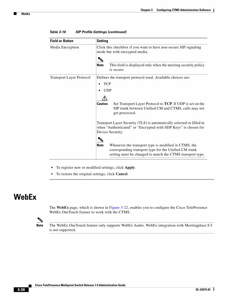
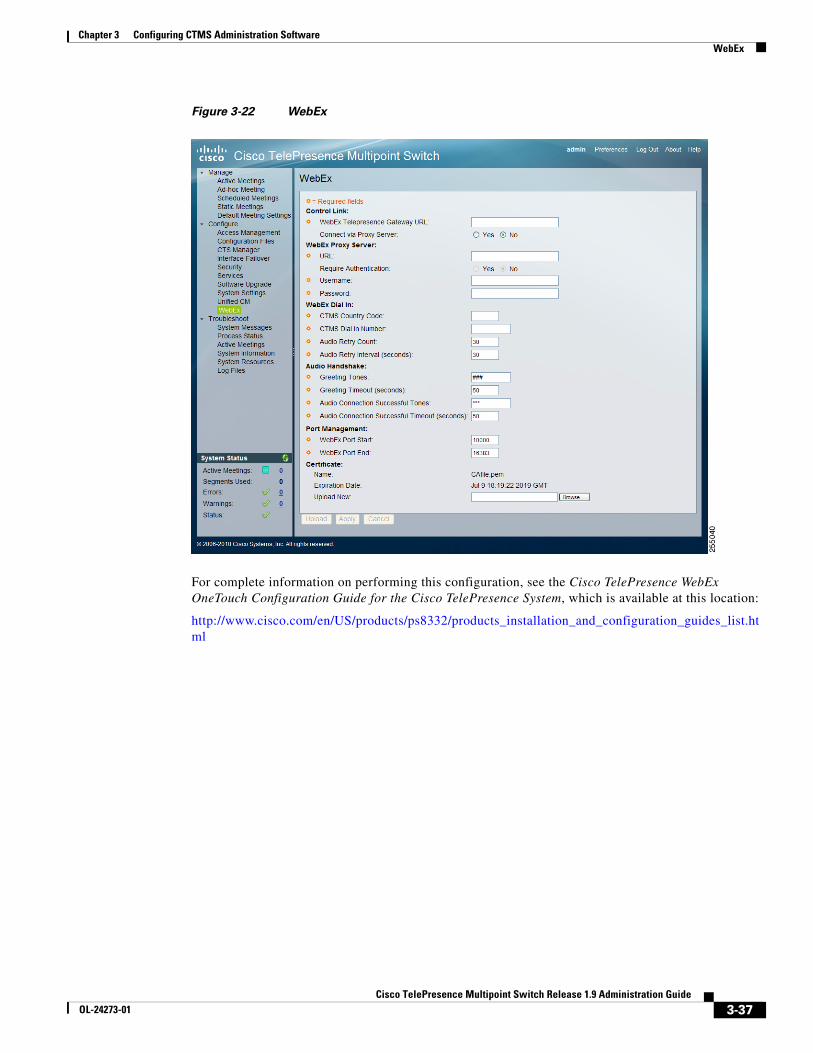
WebEx The WebEx page, which is shown in Figure 3-22, enables you to configure the Cisco TelePresence WebEx OneTouch feature to work with the CTMS.
Note The WebEx OneTouch feature only supports WebEx Audio. WebEx integration with Meetingplace 8.5 is not supported.
Media Encryption Click this checkbox if you want to have non-secure SIP signaling mode but with encrypted media.
Note This field is displayed only when the meeting security policy is secure.
Transport Layer Protocol Defines the transport protocol used. Available choices are:
• TCP
• UDP
Caution Set Transport Layer Protocol to TCP. If UDP is set on the SIP trunk between Unified CM and CTMS, calls may not get processed.
Transport Layer Security (TLS) is automatically selected or filled in when “Authenticated” or “Encrypted with SDP Keys” is chosen for Device Security.
Note Whenever the transport type is modified in CTMS, the corresponding transport type for the Unified CM trunk setting must be changed to match the CTMS transport type.
Table 3-16 SIP Profile Settings (continued)
Field or Button Setting
3-36Cisco TelePresence Multipoint Switch Release 1.9 Administration Guide
OL-24273-01
Chapter 3 Configuring CTMS Administration Software WebEx
Figure 3-22 WebEx
For complete information on performing this configuration, see the Cisco TelePresence WebEx OneTouch Configuration Guide for the Cisco TelePresence System, which is available at this location:
http://www.cisco.com/en/US/products/ps8332/products_installation_and_configuration_guides_list.html
3-37Cisco TelePresence Multipoint Switch Release 1.9 Administration Guide
OL-24273-01

Chapter 3 Configuring CTMS Administration Software WebEx
3-38Cisco TelePresence Multipoint Switch Release 1.9 Administration Guide
OL-24273-01