configuration space course: introduction to autonomous mobile robotics prof. jaebyung park...
TRANSCRIPT
Configuration SpaceCourse: Introduction to Autonomous Mobile Robotics
Prof. Jaebyung ParkIntelligent Systems & Robotics Lab.
Division of Electronic Engineering
Chonbuk National Univerisity
Presented by:Ram Kaji Budhathoki
Student ID: 201155431
Ansu Man Singh
Student ID:201150875
Basic Terminologies• System
A set of particles.
• Configuration
The location of every particle in the system.
• Configuration Space
The set of all possible configurations of the system.
• Degrees of Freedom
The independent ways in which the configurations of a system can change.
• Path
A continuous curve on the configuration space.
• Trajectory
A continuous curve on the configuration space parameterized by time.
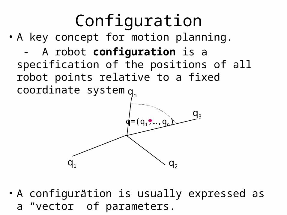
Configuration • A key concept for motion planning.
- A robot configuration is a specification of the positions of all robot points relative to a fixed coordinate system
• A configuration is usually expressed as a “vector” of parameters.
q=(q1,…,qn)
q1 q2
q3
qn
Configuration Space
• Space of all its possible configurations of the system
• But the topology of this space is usually not that of a Cartesian space
Circular Mobile Robot
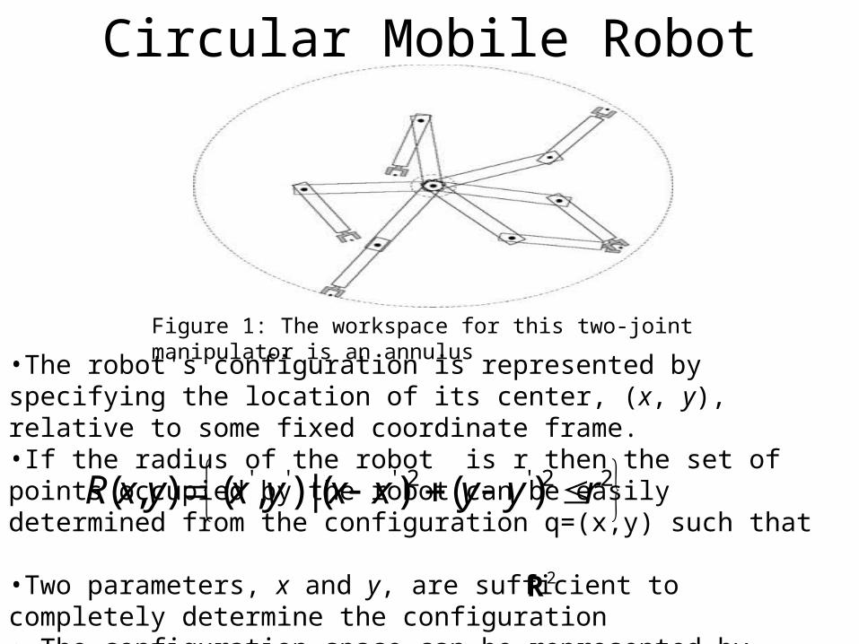
Figure 1: The workspace for this two-joint manipulator is an annulus
•The robot's configuration is represented by specifying the location of its center, (x, y), relative to some fixed coordinate frame. •If the radius of the robot is r then the set of points occupied by the robot can be easily determined from the configuration q=(x,y) such that
•Two parameters, x and y, are sufficient to completely determine the configuration • The configuration space can be represented by once a coordinate frame in the plane has been chosen.
' ' ' 2 ' 2 2( , ) ( , ) | ( ) ( )R x y x y x x y y r
2R
Two-Joint Planar Robot Arm
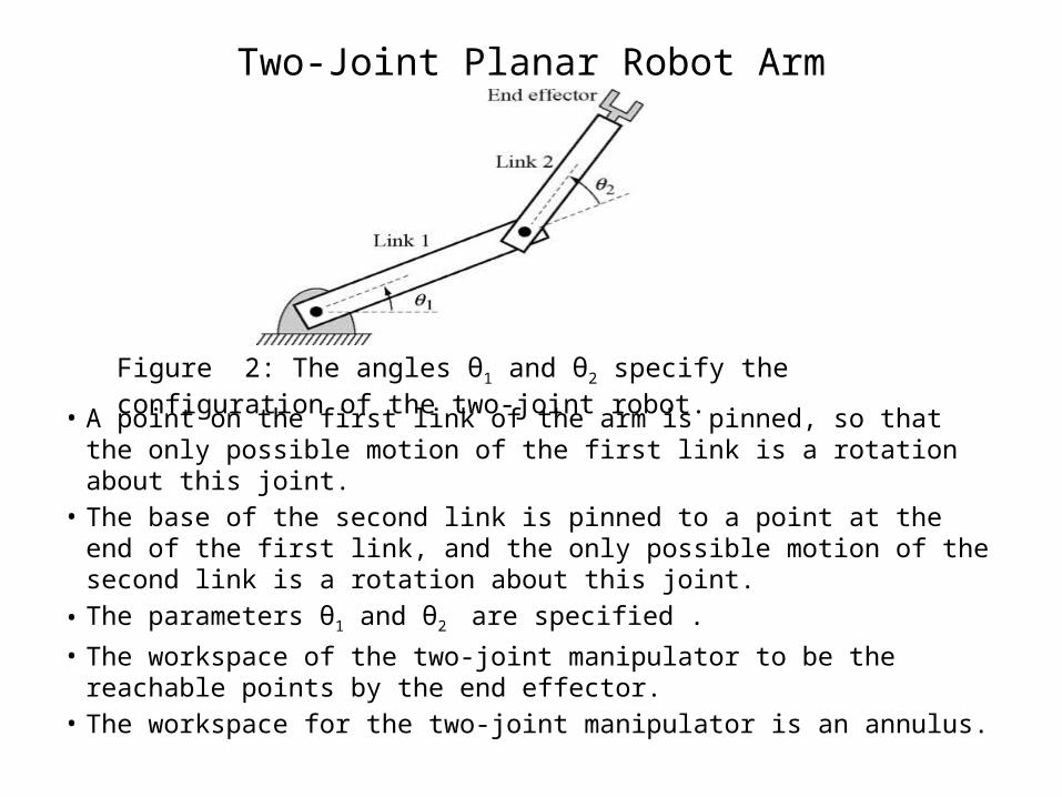
• A point on the first link of the arm is pinned, so that the only possible motion of the first link is a rotation about this joint.
• The base of the second link is pinned to a point at the end of the first link, and the only possible motion of the second link is a rotation about this joint.
• The parameters θ1 and θ2 are specified .
• The workspace of the two-joint manipulator to be the reachable points by the end effector.
• The workspace for the two-joint manipulator is an annulus.
Figure 2: The angles θ1 and θ2 specify the configuration of the two-joint robot.
A Two Joint Manipulator
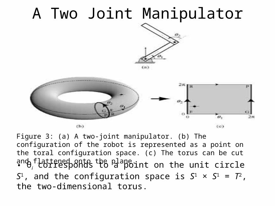
Figure 3: (a) A two-joint manipulator. (b) The configuration of the robot is represented as a point on the toral configuration space. (c) The torus can be cut and flattened onto the plane.
• θi corresponds to a point on the unit circle S1, and the configuration space is S1 × S1 = T2, the two-dimensional torus.

Difference in the Configuration Space
• It is seen that the configuration spaces of both the translating mobile robot and the two-joint manipulator are two-dimensional, but they are quite different.
• The torus T2 is doughnut-shaped with finite area, while is flat with infinite area.
2R
Obstacles in the Configuration Space
• A point in the configuration space corresponds to a particular configuration of the system. If there are obstacles, some configurations of the system will not be possible.
• The space of configurations that do not collide with obstacles is the free configuration space;
• The space of points in configuration space that cause collisions is the "configuration space obstacles”.
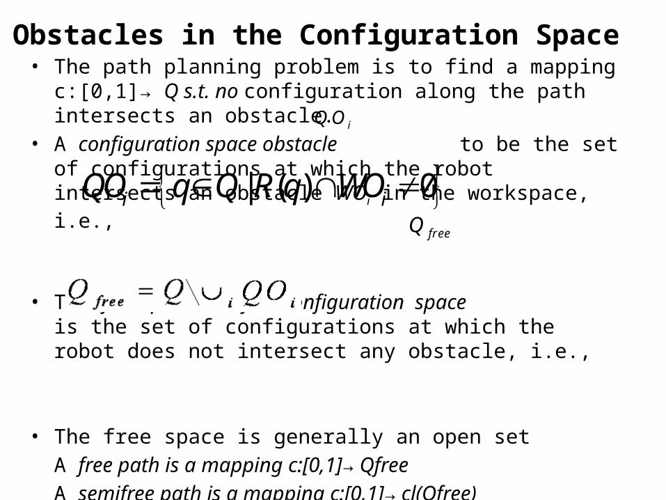
Obstacles in the Configuration Space• The path planning problem is to find a mapping c:[0,1]→ Q s.t. no
configuration along the path intersects an obstacle.• A configuration space obstacle to be the set of configurations at
which the robot intersects an obstacle WOi in the workspace, i.e.,
• The free space or free configuration space is the set of configurations at which the robot does not intersect any obstacle, i.e.,
• The free space is generally an open set
A free path is a mapping c:[0,1]→ Qfree
A semifree path is a mapping c:[0,1]→ cl(Qfree)
| ( ) 0i iQO q Q R q WO
iQO
freeQ
Trace Boundary of Workspace Circular Mobile Robot
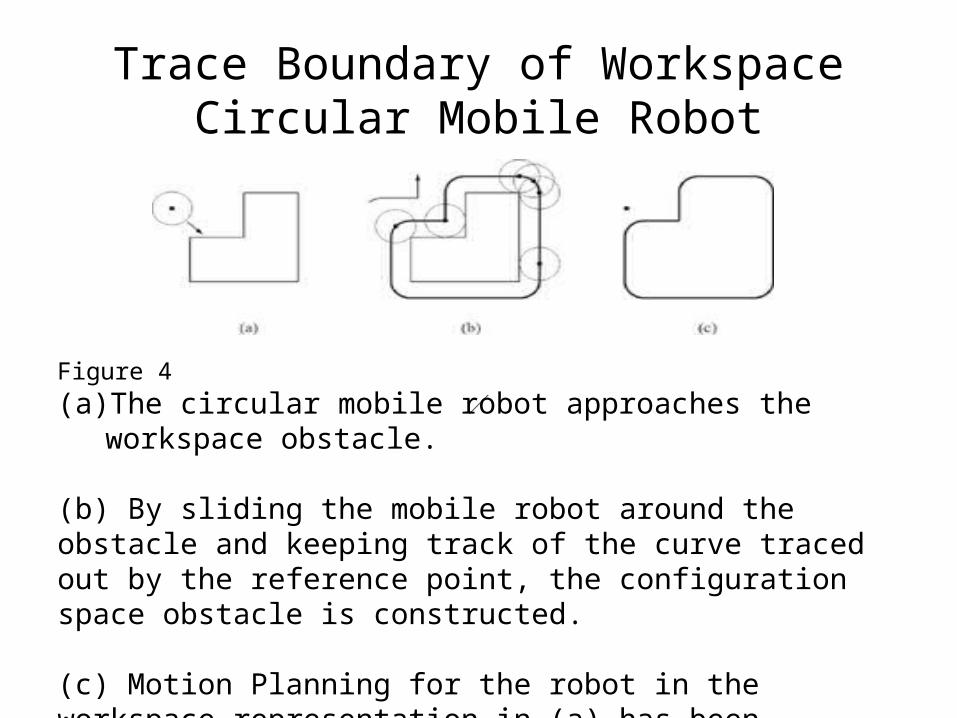
Figure 4
(a) The circular mobile robot approaches the workspace obstacle. (b) By sliding the mobile robot around the obstacle and keeping track of the curve traced out by the reference point, the configuration space obstacle is constructed.
(c) Motion Planning for the robot in the workspace representation in (a) has been transformed into motion planning for a point robot in the configuration space.
Workspace and Configuration space
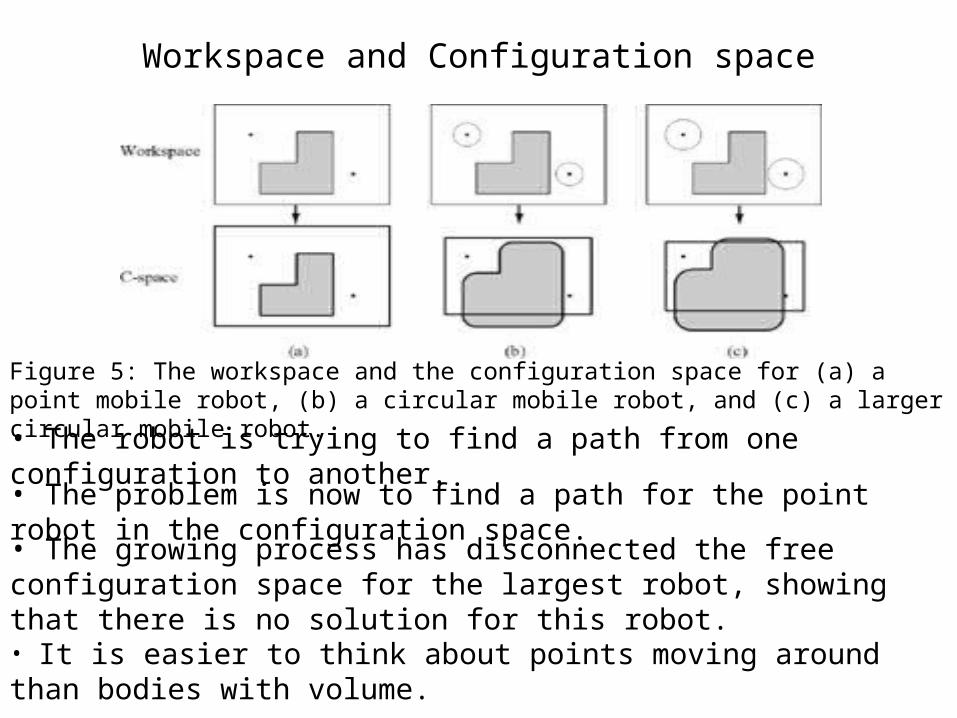
Figure 5: The workspace and the configuration space for (a) a point mobile robot, (b) a circular mobile robot, and (c) a larger circular mobile robot.
• The robot is trying to find a path from one configuration to another.
• The problem is now to find a path for the point robot in the configuration space.• The growing process has disconnected the free configuration space for the largest robot, showing that there is no solution for this robot.
• It is easier to think about points moving around than bodies with volume.
The Dimension of the Configuration Space
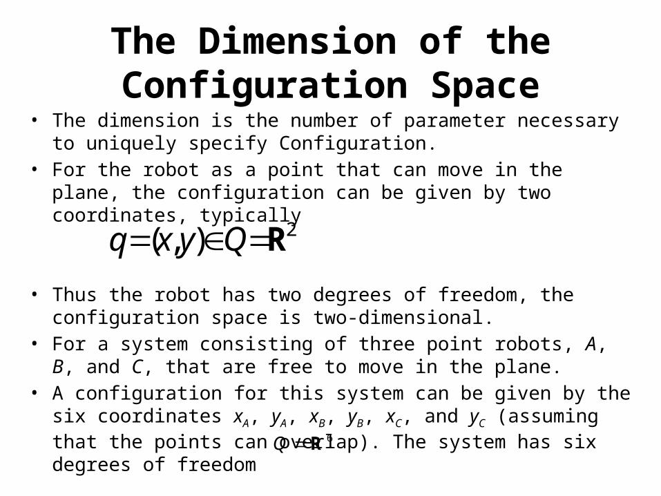
• The dimension is the number of parameter necessary to uniquely specify Configuration.
• For the robot as a point that can move in the plane, the configuration can be given by two coordinates, typically
• Thus the robot has two degrees of freedom, the configuration space is two-dimensional.
• For a system consisting of three point robots, A, B, and C, that are free to move in the plane.
• A configuration for this system can be given by the six coordinates xA, yA, xB, yB, xC, and yC (assuming that the points can overlap). The system has six degrees of freedom
2( , )q x y Q R
6Q R
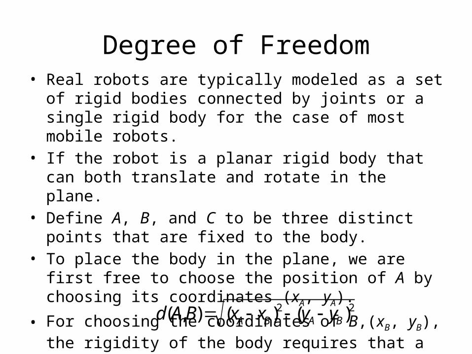
Degree of Freedom• Real robots are typically modeled as a set of rigid bodies
connected by joints or a single rigid body for the case of most mobile robots.
• If the robot is a planar rigid body that can both translate and rotate in the plane.
• Define A, B, and C to be three distinct points that are fixed to the body.
• To place the body in the plane, we are first free to choose the position of A by choosing its coordinates (xA, yA).
• For choosing the coordinates of B,(xB, yB), the rigidity of the body requires that a constant distance d( A, B) from A should be maintained: 2 2( , ) ( ) ( )A B A Bd A B x x y y
Degree of Freedom
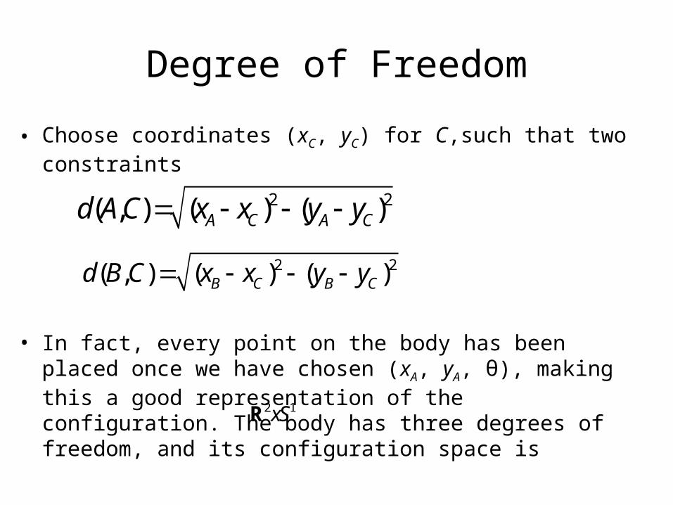
• Choose coordinates (xC, yC) for C,such that two constraints
• In fact, every point on the body has been placed once we have chosen (xA, yA, θ), making this a good representation of the configuration. The body has three degrees of freedom, and its configuration space is
2 2( , ) ( ) ( )A C A Cd A C x x y y
2 2( , ) ( ) ( )B C B Cd B C x x y y
2 1xSR
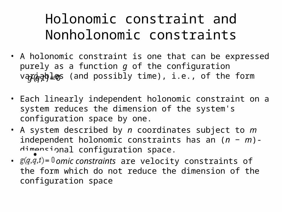
Holonomic constraint and Nonholonomic constraints
• A holonomic constraint is one that can be expressed purely as a function g of the configuration variables (and possibly time), i.e., of the form
• Each linearly independent holonomic constraint on a system reduces the dimension of the system's configuration space by one.
• A system described by n coordinates subject to m independent holonomic constraints has an (n − m)-dimensional configuration space.
• Nonholonomic constraints are velocity constraints of the form which do not reduce the dimension of the configuration space
( , ) 0g q t
Open Chain Robot
• The degrees of freedom of an open-chain jointed robot, also known as a serial mechanism, by adding the degrees of freedom at each joint.
• Common joints with one degree of freedom are revolute (R) joints, joints which rotate about an axis, and prismatic (P) joints, joints which allow translational motion along an axis.
• The two-joint robot is sometimes called an RR or 2R robot, indicating that both joints are revolute.
• An RP robot, on the other hand, has a revolute joint followed by a prismatic joint.
• Another common joint is a spherical (ball-and-socket) joint, which has three degrees of freedom.
Closed Chain Robot
• A closed-chain robot, also known as a parallel mechanism, is one where the links form one or more closed loops.
• If the mechanism has k links, then one is designated as a stationary "ground" link, and k − 1 links are movable.
• To determine the number of degrees of freedom, each movable link has N degrees of freedom(N=6 for spatial and N=3 for Planar mechanism)
• The system has N (k − 1) degrees of freedom before the joints are taken into account.
• Each of the n joints between the links places N − fi constraints on the feasible motions of the links, where fi is the number of degrees of freedom at joint i (e.g., fi = 1 for a revolute joint, and fi = 3 for a spherical joint).
Grübler's Formula of Mobility
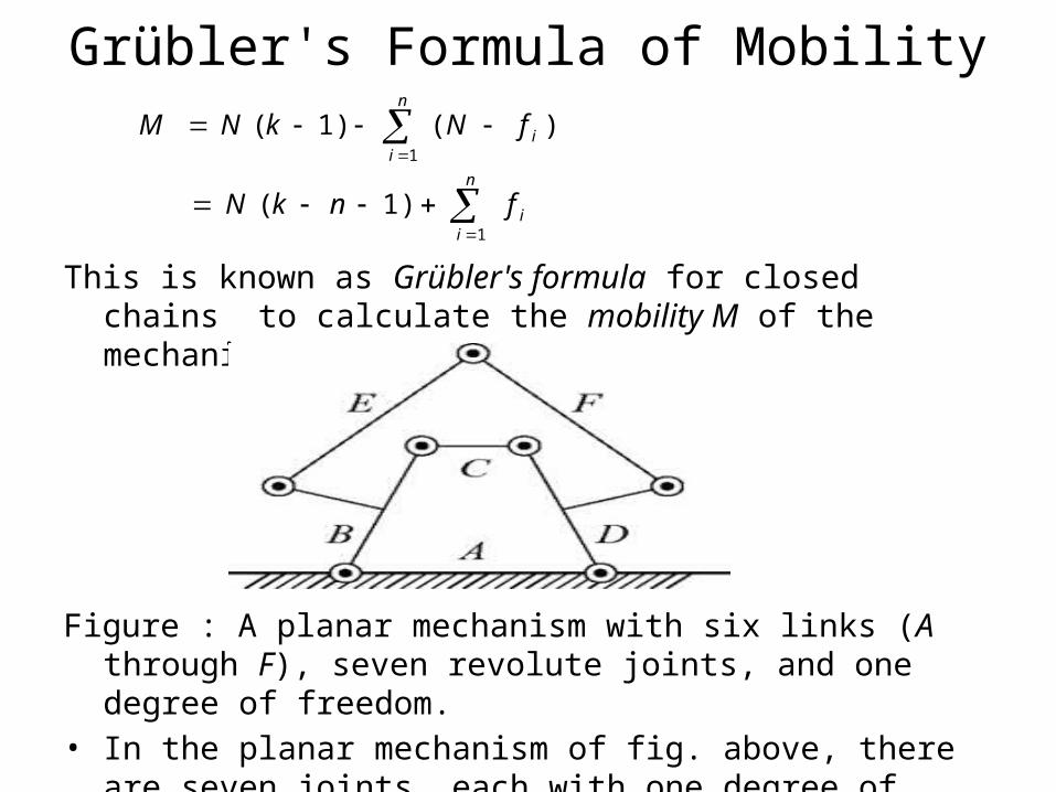
This is known as Grübler's formula for closed chains to calculate the mobility M of the mechanism
Figure : A planar mechanism with six links (A through F), seven revolute joints, and one degree of freedom.
• In the planar mechanism of fig. above, there are seven joints, each with one degree of freedom, and six links, yielding a mobility of
3(6 − 7 − 1) + 7 = 1.
1
( 1) ( )n
ii
M N k N f
1
( 1)n
ii
N k n f
The Topology of the Configuration Space• Topology is the “intrinsic character” of a space• Topology is a branch of mathematics that considers properties of objects
that do not change when the objects are subjected to arbitrary continuous transformations, such as stretching or bending.
• Two space have a different topology if cutting and pasting is required to make them the same
• Example :A polygon drawn on a rubber sheet. • Why study the Topology
- Extend results from one space to another: spheres to stars
- Impact the representation
- Know where you are
- we can derive a path-planning algorithm for one kind of topological space, then that algorithm may carry over to other spaces that are topologically equivalent.
• A basic mathematical mechanism for talking about topology is the homeomorphism.
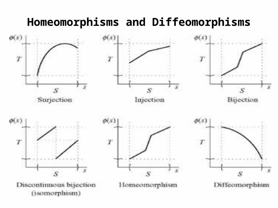
Homeomorphisms and Diffeomorphisms
• Mappings:
– φ: S → T
– If each elements of φ goes to a unique T, φ is injective (or 1-1)
– If each element of T has a corresponding preimage in S, then φ is surjective (or onto).
– If φ is surjective and injective, then it is bijective (in which case an inverse, φ-1 exists).
– φ is smooth if derivatives of all orders exist (we say φ is C∞)• If φ: S → T is a bijection, and both φ and φ-1 are continuous, φ is a
homeomorphism; if such a φ exists, S and T are homeomorphic.• If homeomorphism where both φ and φ-1 are smooth is a
diffeomorphism.
Homeomorphisms and Diffeomorphisms
Manifolds• A manifold is a special type of surface that is locally similar to Rd.
i.e, at every point on the surface, it is possible to attach a local coordinate system with d dimensions.
• If the configuration space is a manifold, there is a precise way to count the degrees of freedom of a system: the number of degrees of freedom is equal to the dimensionality of the manifold.
• A space S locally diffeomorphic (homeomorphic) to a space T if each p S there is a neighborhood containing it for which a ∈diffeomorphism (homeomorphism) to some neighborhood of T exists.
• S1 is locally diffeomorphic to ℜ1
• The sphere is locally diffeomorphic to the plane (as is the torus)
• A set S is a k-dimensional manifold if it is locally homeomorphic to ℜk
Charts and Differentiable Manifolds• A Chart is a pair (U,φ) such that U is an open set in a k-dimensional
manifold and φ is a diffeomorphism from U to some open set in ℜk
– think of this as a “coordinate system” for U (e.g. lines of latitude and longitude away form the poles).
– The inverse map is a parameterization of the manifold
• Many manifolds require more than one chart to cover (e.g. the circle
requires at least 2)
• An atlas is a set of charts that
– cover a manifold
– are smooth where they overlap
• A set S is a differentiable manifold of dimension n if there exists an atlas from S to ℜn
– For example, this is what allows us (locally) to view the (spherical) earth as flat and talk about translational velocities upon it.
Connectedness and Compactness•A manifold is path-connected if there is a path between any two
points.
• A space is compact if it is closed and bounded
– configuration space might be either depending on how we model things
• For manifolds, we can
– live with “global” parameterizations that introduce odd singularities (e.g. angle/elevation on a sphere)
– use atlases
– embed in a higher-dimensional space using constraints
• The later is preferred as it often avoids the complexities
associated with singularities and/or multiple overlapping maps
Embeddings of Manifolds
• Representation of Manifolds of k dimensions with more than k variables can be used to achieve single global representation.
• It is called embeddings of Manifolds• E.g for a sphere of 1 dimension we define
here S1 is represented by R2 .
• Similarly for the representation of T2 (a two dimensional manifold) R3 is used.
S1 ={(x, y) | x2 + y2 = 1};
Matrix representation of Rigid body Configuration
• Orientation and position of any frame can be represented in Matrix form
• For the representation of orientation only SO(n) matrix group is used where as for the position and orientation both SE(n) is used.
Matrix representation of Rigid body Configuration
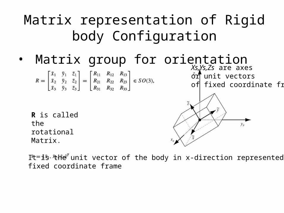
• Matrix group for orientation
R is called the rotational Matrix.
Xs,Ys,Zs are axes or unit vectors of fixed coordinate frame
It is the unit vector of the body in x-direction represented in fixed coordinate frame
Matrix representation of Rigid body Configuration
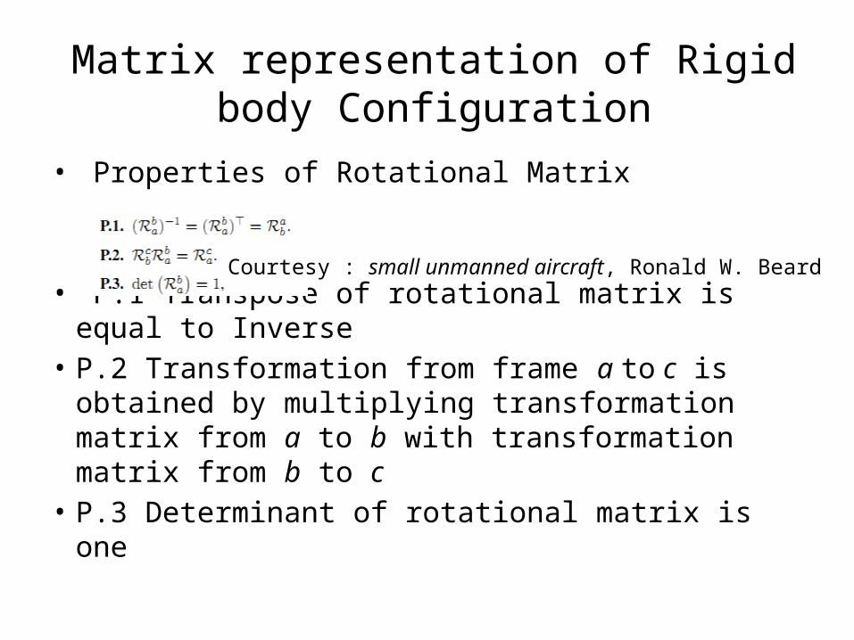
• Properties of Rotational Matrix
• P.1 Transpose of rotational matrix is equal to Inverse
• P.2 Transformation from frame a to c is obtained by multiplying transformation matrix from a to b with transformation matrix from b to c
• P.3 Determinant of rotational matrix is one
Courtesy : small unmanned aircraft, Ronald W. Beard
Matrix representation of Rigid body Configuration
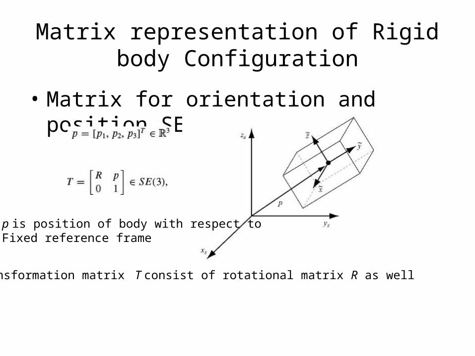
• Matrix for orientation and position SE(n)
Transformation matrix T consist of rotational matrix R as well
p is position of body with respect toFixed reference frame
Matrix representation of Rigid body Configuration
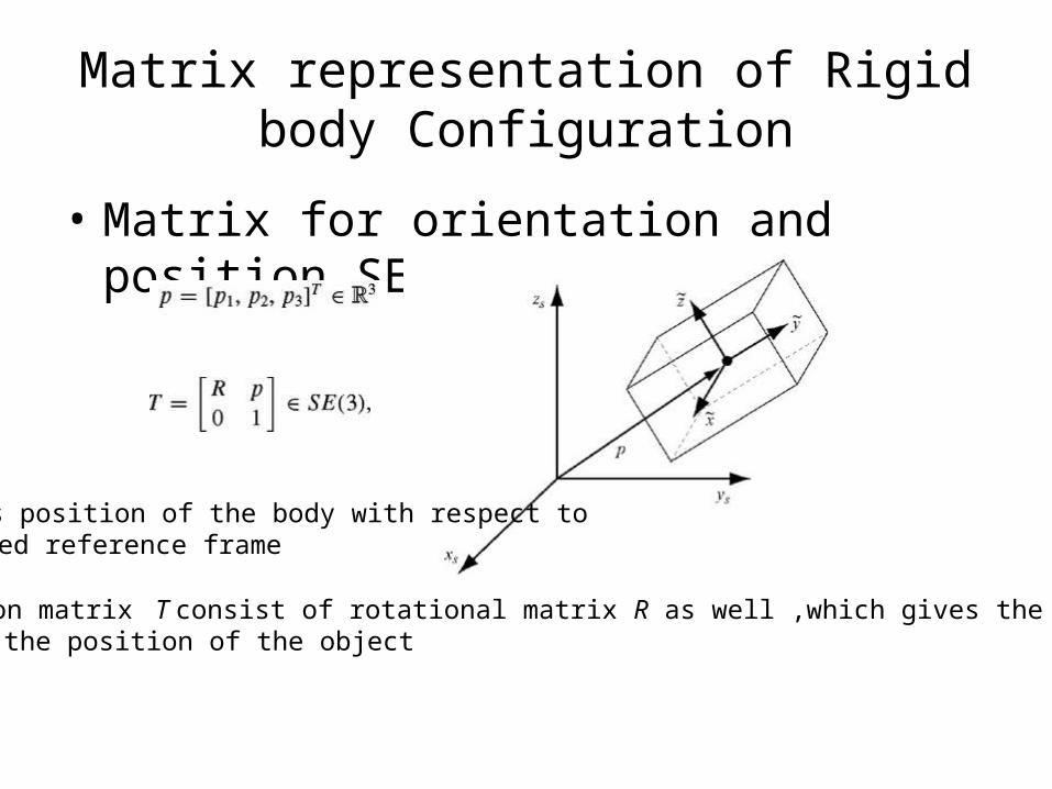
• Matrix for orientation and position SE(n)
p is position of the body with respect toFixed reference frame
Transformation matrix T consist of rotational matrix R as well ,which gives the orientation and p gives the position of the object
Matrix representation of Rigid body Configuration
• Usage of Matrix group SE(3)1. Represent rigid-body configurations2. Change the reference frame for the
representation of a configuration or a point3. Displace a configuration or a point
Matrix representation of Rigid body Configuration
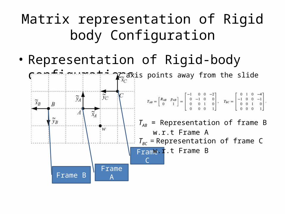
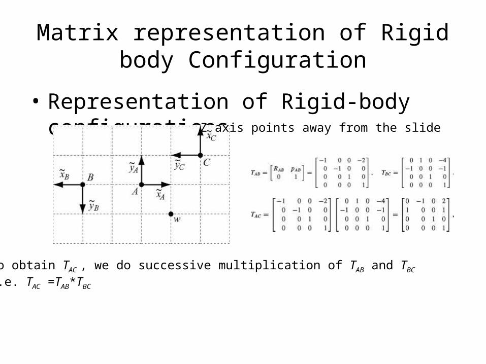
• Representation of Rigid-body configurations
Frame AFrame B
Frame C
TAB = Representation of frame B w.r.t Frame A
TBC = Representation of frame C w.r.t Frame B
Z axis points away from the slide
Matrix representation of Rigid body Configuration
• Representation of Rigid-body configurations
To obtain TAC , we do successive multiplication of TAB and TBC
i.e. TAC =TAB*TBC
Z axis points away from the slide
Matrix representation of Rigid body Configuration
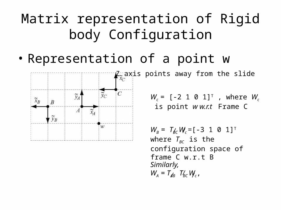
• Representation of a point wZ axis points away from the slide
Wc = [-2 1 0 1]T , where Wc is point w w.r.t Frame C
WB = TBC Wc =[-3 1 0 1]T where TBC is the configuration space of frame C w.r.t B
Similarly,WA = TAB TBC Wc,
Matrix representation of Rigid body Configuration
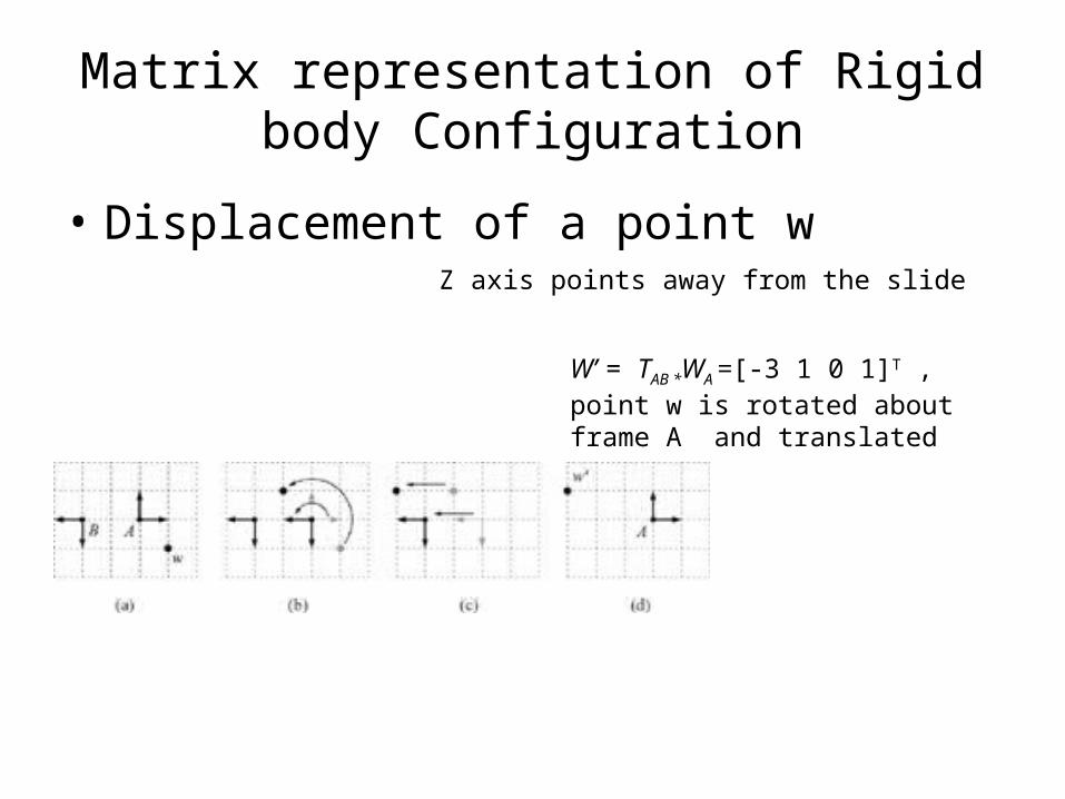
• Displacement of a point wZ axis points away from the slide
W’ = TAB *WA =[-3 1 0 1]T , point w is rotated about frame A and translated
Matrix representation of Rigid body Configuration
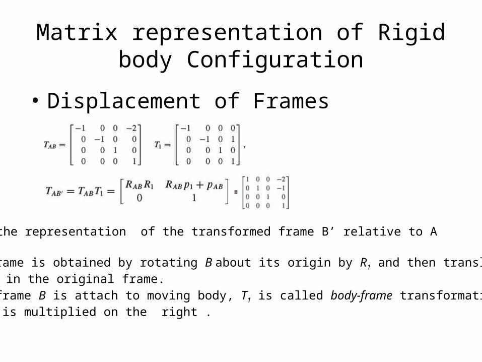
• Displacement of Frames
•TAB’ is the representation of the transformed frame B’ relative to A
•This frame is obtained by rotating B about its origin by R1 and then translating By p1 in the original frame.•Since frame B is attach to moving body, T1 is called body-frame transformation if it is multiplied on the right .

Matrix representation of Rigid body Configuration
• Displacement of Frames
•TAB” is the representation of the transformed frame B” relative to A
•This frame is obtained by rotating B about the origin of A by R1 and then translating By p1 in the A frame.•Since frame A is stationary frame, T1 is called world-frame transformation if it is multiplied on the left .
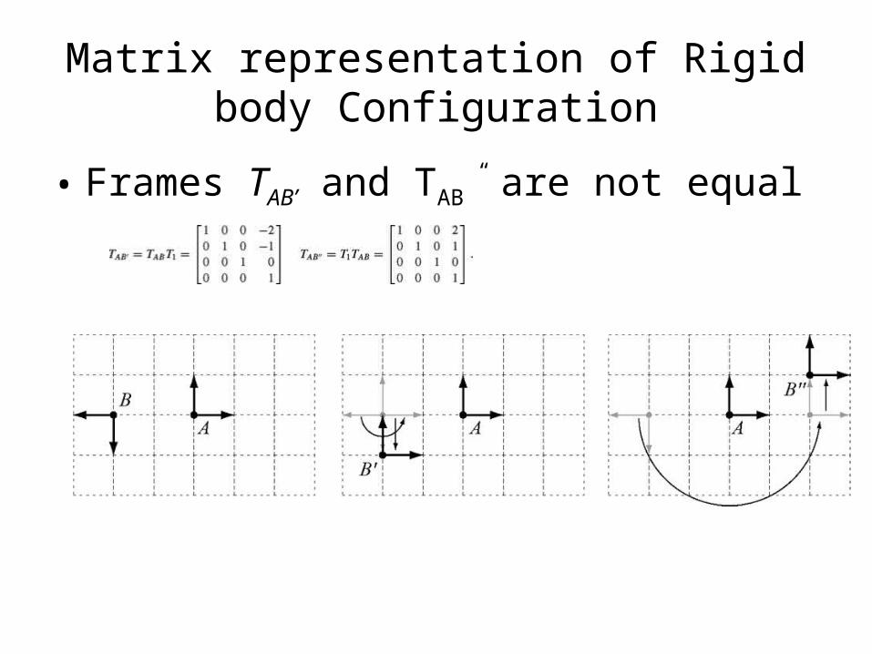
Matrix representation of Rigid body Configuration
• Frames TAB’ and TAB” are not equal
Parameterization of SO(3)
• SO(3) is parameterized by three angles known as Euler angles. They are given by (Ψ,θ,Φ)
• Yaw angle Ψ: is angle of rotating about z-axis• Pitch angle θ, is angle of rotating about Y-axis• Roll angle Φ is angle of rotation about z-axis
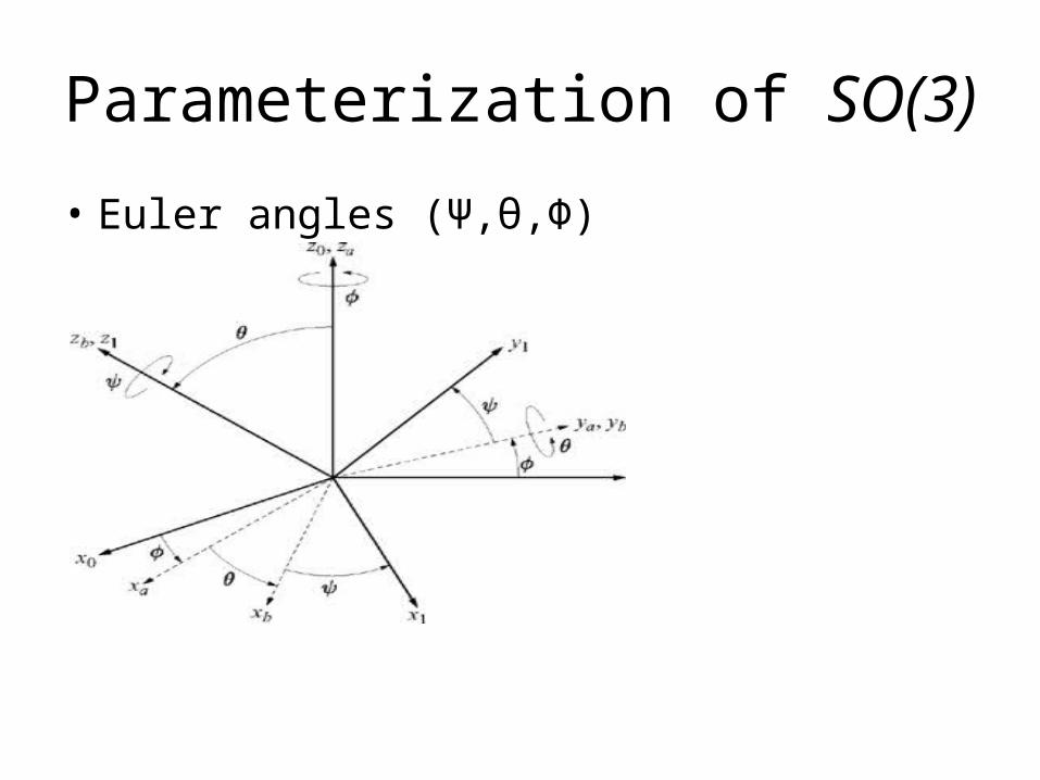
Parameterization of SO(3)
• Euler angles (Ψ,θ,Φ)

Examples of configuration spaces
Type of robot Representation of Q
Mobile robot translating in the plane R2
Mobile robot translating and rotating in the plane
R2* SO(2)
Rigid body translating in the three-space R3
A spacecraft R3*SO(3)
An n-joint revolute arm Tn
A planar mobile robot with an attached n-joint arm
SE(2) × Tn
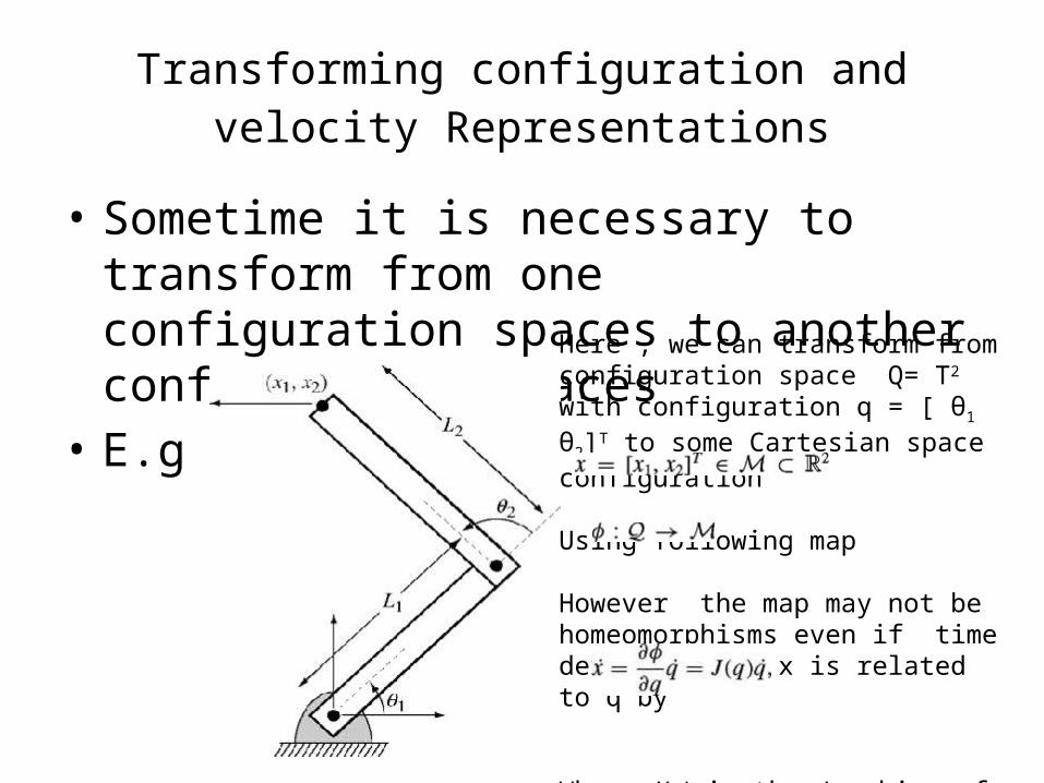
Transforming configuration and velocity Representations
• Sometime it is necessary to transform from one configuration spaces to another configuration spaces
• E.gHere , we can transform from configuration space Q= T2 with configuration q = [ θ1 θ2]T to some Cartesian space configuration
Using following map
However the map may not be homeomorphisms even if time derivative of x is related to q by
Where J(q) is the Jacobian of the map φ

Thank you