condition evaluation of bridge deck surface structure … · condition evaluation of bridge deck...
TRANSCRIPT
Condition Evaluation of Bridge Deck Surface Structure by Using State ofthe Art NDT- Techniques
Guy RAPAPORTRamboll Finland Oy, Bridge Asset Management, Kuopio, Finland; Phone +358 40 8245622, e-mail:
Abstract
This paper introduces recent experience of Ramboll Finland bridge inspectors and NDT- experts in conditionevaluation of road bridges deck surface structure by using state of the art NDT- techniques.This paper focuses onpossible benefits of applying NDT- techniques in condition evaluation of road bridge deck surface structures. Inaddition, examples from several actual test cases are reviewed. Only a simplified description concerning thetechnical properties of the used NDT- techniques will be given here.
Keywords: Bridges, bridge deck surface structure, NDT, Impulse-Response, Impact-Echo, bridge specialinspection, quality assurance, bridge repair
1. Main Terms
In this section definitions of the most relevant terms related to this paper are given.
Bridge deck: this paper refers to concrete deck slab of a road bridges. The main function of abridge deck slab is to support the vehicular loads and to distribute these loads to the bridgesuperstructure main supports (girder bridges). In case of slab bridge type the deck has also themain vehicular loads carrying role. In addition to the vehicular loads a bridge deck carriesother loads (wind, snow, dead load etc.).The mentioned bridge types are the most commonroad bridge types in use today.
Bridge deck surface structures: refers to the different layers applied on top of a bridge deckslab. The surface structures in Finland are usually composed of asphalt layers (wearing courseand base course), protective layer (asphalt mass or concrete) and waterproofing layers (sheetmembranes, epoxy treatment, asphalt mastic etc.).
The bridge deck surface structure layers must meet different requirements such as evenness,resistance to aging and deformations etc. The surface structure layers have to be well bondedto each other in order to ensure long term functionality and intactness. The waterproofing(sealing) layer must be water tight and well bonded to its substrate, the bridge deck uppersurface.
The upper part of the bridge deck slab concrete is also considered to be part of the bridge decksurface structures, as it functions as the base layer of the surface structures. The upper part ingenerally means several cm of the concrete top.
Well functioning surface structures will ensure road users safety, good distribution ofloads and long term durability of the structure.
A typical bridge deck surface structure used in Finland is shown in figure no. 1 taken from theFinnish Transport Agency (NCCI 1, guide no. 24/2014).
International Symposium Non-Destructive Testing in Civil Engineering (NDT-CE)
September 15 - 17, 2015, Berlin, Germany
Mor
e In
fo a
t Ope
n A
cces
s D
atab
ase
ww
w.n
dt.n
et/?
id=
1826
7
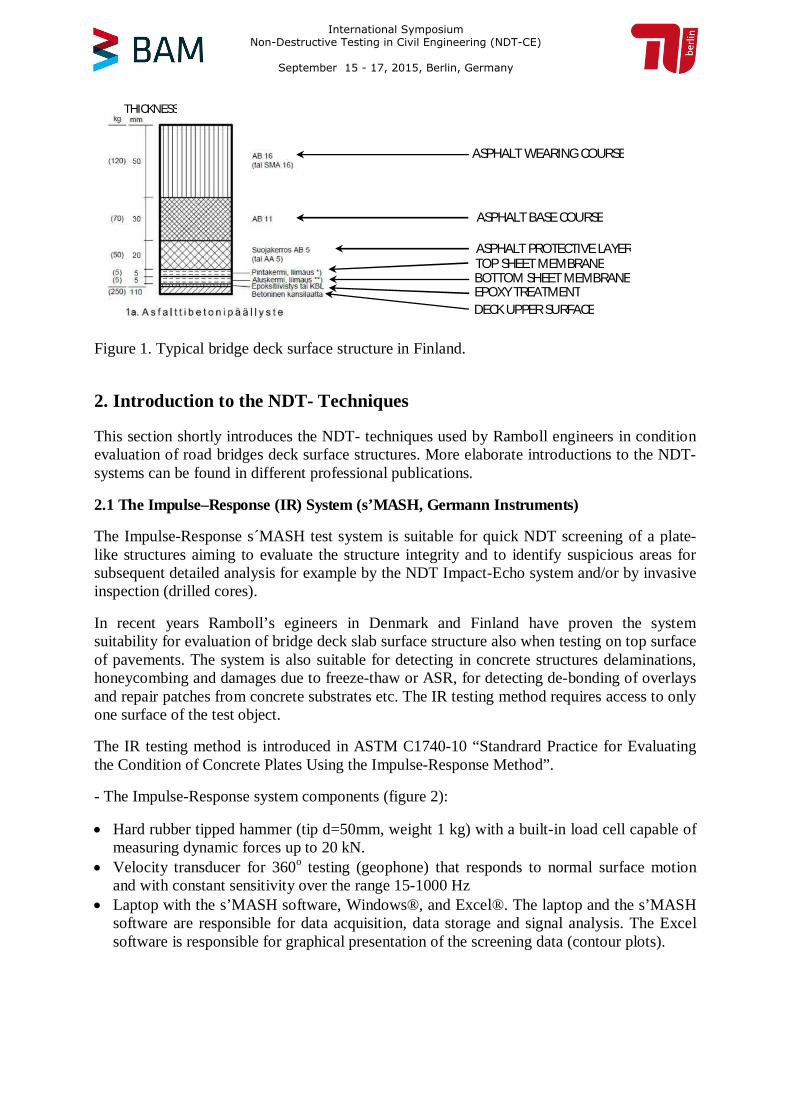
Figure 1. Typical bridge deck surface structure in Finland.
2. Introduction to the NDT- Techniques
This section shortly introduces the NDT- techniques used by Ramboll engineers in conditionevaluation of road bridges deck surface structures. More elaborate introductions to the NDT-systems can be found in different professional publications.
2.1 The Impulse–Response (IR) System (s’MASH, Germann Instruments)
The Impulse-Response s´MASH test system is suitable for quick NDT screening of a plate-like structures aiming to evaluate the structure integrity and to identify suspicious areas forsubsequent detailed analysis for example by the NDT Impact-Echo system and/or by invasiveinspection (drilled cores).
In recent years Ramboll’s egineers in Denmark and Finland have proven the systemsuitability for evaluation of bridge deck slab surface structure also when testing on top surfaceof pavements. The system is also suitable for detecting in concrete structures delaminations,honeycombing and damages due to freeze-thaw or ASR, for detecting de-bonding of overlaysand repair patches from concrete substrates etc. The IR testing method requires access to onlyone surface of the test object.
The IR testing method is introduced in ASTM C1740-10 “Standrard Practice for Evaluatingthe Condition of Concrete Plates Using the Impulse-Response Method”.
- The Impulse-Response system components (figure 2):
· Hard rubber tipped hammer (tip d=50mm, weight 1 kg) with a built-in load cell capable ofmeasuring dynamic forces up to 20 kN.· Velocity transducer for 360o testing (geophone) that responds to normal surface motionand with constant sensitivity over the range 15-1000 Hz· Laptop with the s’MASH software, Windows®, and Excel®. The laptop and the s’MASHsoftware are responsible for data acquisition, data storage and signal analysis. The Excelsoftware is responsible for graphical presentation of the screening data (contour plots).
EPOXYTREATMENTDECK UPPER SURFACE
BOTTOM SHEET MEMBRANETOP SHEET MEMBRANEASPHALT PROTECTIVE LAYER
ASPHALT BASE COURSE
ASPHALT WEARING COURSE
THICKNESS
International Symposium Non-Destructive Testing in Civil Engineering (NDT-CE)
September 15 - 17, 2015, Berlin, Germany
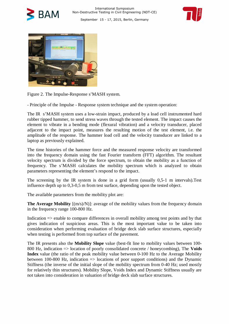
Figure 2. The Impulse-Response s’MASH system.
- Principle of the Impulse - Response system technique and the system operation:
The IR s’MASH system uses a low-strain impact, produced by a load cell instrumented hardrubber tipped hammer, to send stress waves through the tested element. The impact causes theelement to vibrate in a bending mode (flexural vibration) and a velocity transducer, placedadjacent to the impact point, measures the resulting motion of the test element, i.e. theamplitude of the response. The hammer load cell and the velocity transducer are linked to alaptop as previously explained.
The time histories of the hammer force and the measured response velocity are transformedinto the frequency domain using the fast Fourier transform (FFT) algorithm. The resultantvelocity spectrum is divided by the force spectrum, to obtain the mobility as a function offrequency. The s’MASH calculates the mobility spectrum which is analyzed to obtainparameters representing the element’s respond to the impact.
The screening by the IR system is done in a grid form (usually 0,5-1 m intervals).Testinfluence depth up to 0,3-0,5 m from test surface, depending upon the tested object.
The available parameters from the mobility plot are:
The Average Mobility [(m/s)/N)]: average of the mobility values from the frequency domainin the frequency range 100-800 Hz.
Indication => enable to compare differences in overall mobility among test points and by thatgives indication of suspicious areas. This is the most important value to be taken intoconsideration when performing evaluation of bridge deck slab surface structures, especiallywhen testing is performed from top surface of the pavement.
The IR presents also theMobility Slope value (best-fit line to mobility values between 100-800 Hz, indication => location of poorly consolidated concrete / honeycombing), TheVoidsIndex value (the ratio of the peak mobility value between 0-100 Hz to the Average Mobilitybetween 100-800 Hz, indication => locations of poor support conditions) and the DynamicStiffness (the inverse of the initial slope of the mobility spectrum from 0-40 Hz; used mostlyfor relatively thin structures). Mobility Slope, Voids Index and Dynamic Stiffness usually arenot taken into consideration in valuation of bridge deck slab surface structures.
International Symposium Non-Destructive Testing in Civil Engineering (NDT-CE)
September 15 - 17, 2015, Berlin, Germany
- The Impulse – Response s’MASH data presentation:
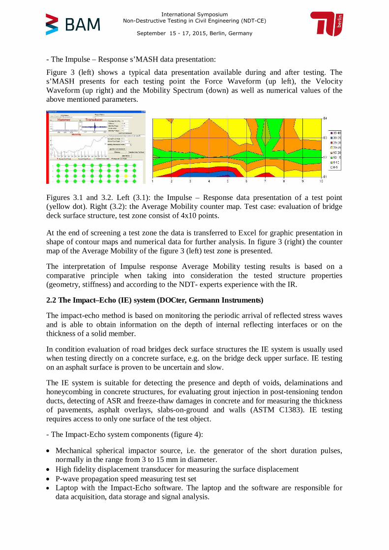
Figure 3 (left) shows a typical data presentation available during and after testing. Thes’MASH presents for each testing point the Force Waveform (up left), the VelocityWaveform (up right) and the Mobility Spectrum (down) as well as numerical values of theabove mentioned parameters.
Figures 3.1 and 3.2. Left (3.1): the Impulse – Response data presentation of a test point(yellow dot). Right (3.2): the Average Mobility counter map. Test case: evaluation of bridgedeck surface structure, test zone consist of 4x10 points.
At the end of screening a test zone the data is transferred to Excel for graphic presentation inshape of contour maps and numerical data for further analysis. In figure 3 (right) the countermap of the Average Mobility of the figure 3 (left) test zone is presented.
The interpretation of Impulse response Average Mobility testing results is based on acomparative principle when taking into consideration the tested structure properties(geometry, stiffness) and according to the NDT- experts experience with the IR.
2.2 The Impact–Echo (IE) system (DOCter, Germann Instruments)
The impact-echo method is based on monitoring the periodic arrival of reflected stress wavesand is able to obtain information on the depth of internal reflecting interfaces or on thethickness of a solid member.
In condition evaluation of road bridges deck surface structures the IE system is usually usedwhen testing directly on a concrete surface, e.g. on the bridge deck upper surface. IE testingon an asphalt surface is proven to be uncertain and slow.
The IE system is suitable for detecting the presence and depth of voids, delaminations andhoneycombing in concrete structures, for evaluating grout injection in post-tensioning tendonducts, detecting of ASR and freeze-thaw damages in concrete and for measuring the thicknessof pavements, asphalt overlays, slabs-on-ground and walls (ASTM C1383). IE testingrequires access to only one surface of the test object.
- The Impact-Echo system components (figure 4):
· Mechanical spherical impactor source, i.e. the generator of the short duration pulses,normally in the range from 3 to 15 mm in diameter.· High fidelity displacement transducer for measuring the surface displacement· P-wave propagation speed measuring test set· Laptop with the Impact-Echo software. The laptop and the software are responsible fordata acquisition, data storage and signal analysis.
International Symposium Non-Destructive Testing in Civil Engineering (NDT-CE)
September 15 - 17, 2015, Berlin, Germany
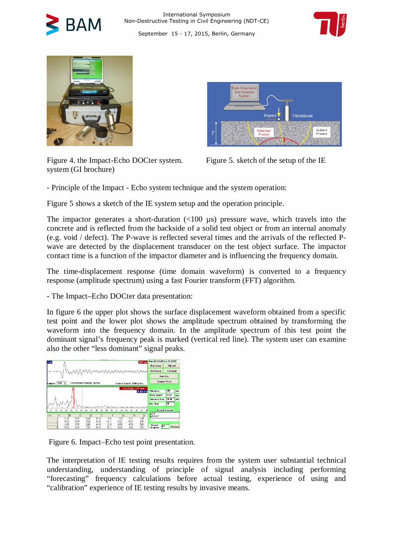
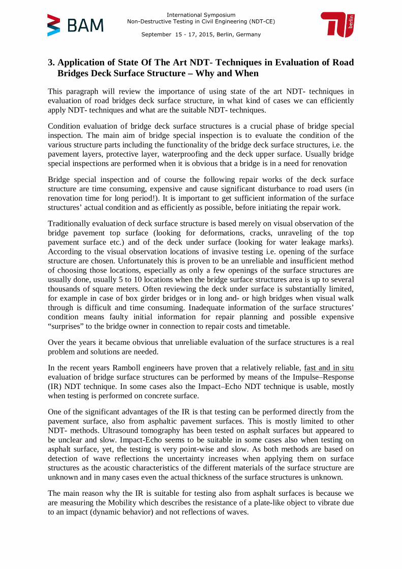
Figure 4. the Impact-Echo DOCter system. Figure 5. sketch of the setup of the IEsystem (GI brochure)
- Principle of the Impact - Echo system technique and the system operation:
Figure 5 shows a sketch of the IE system setup and the operation principle.
The impactor generates a short-duration (<100 µs) pressure wave, which travels into theconcrete and is reflected from the backside of a solid test object or from an internal anomaly(e.g. void / defect). The P-wave is reflected several times and the arrivals of the reflected P-wave are detected by the displacement transducer on the test object surface. The impactorcontact time is a function of the impactor diameter and is influencing the frequency domain.
The time-displacement response (time domain waveform) is converted to a frequencyresponse (amplitude spectrum) using a fast Fourier transform (FFT) algorithm.
- The Impact–Echo DOCter data presentation:
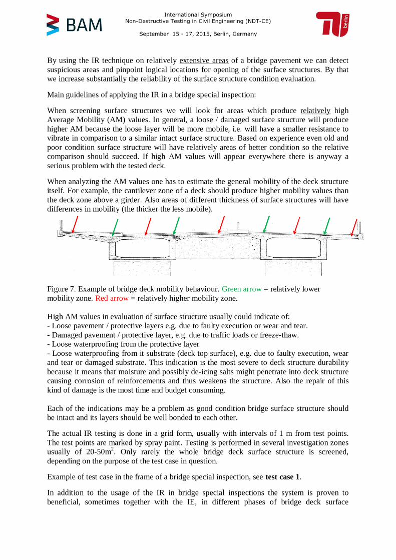
In figure 6 the upper plot shows the surface displacement waveform obtained from a specifictest point and the lower plot shows the amplitude spectrum obtained by transforming thewaveform into the frequency domain. In the amplitude spectrum of this test point thedominant signal’s frequency peak is marked (vertical red line). The system user can examinealso the other “less dominant” signal peaks.
Figure 6. Impact–Echo test point presentation.
The interpretation of IE testing results requires from the system user substantial technicalunderstanding, understanding of principle of signal analysis including performing“forecasting” frequency calculations before actual testing, experience of using and“calibration” experience of IE testing results by invasive means.
International Symposium Non-Destructive Testing in Civil Engineering (NDT-CE)
September 15 - 17, 2015, Berlin, Germany
3. Application of State Of The Art NDT- Techniques in Evaluation of RoadBridges Deck Surface Structure – Why and When
This paragraph will review the importance of using state of the art NDT- techniques inevaluation of road bridges deck surface structure, in what kind of cases we can efficientlyapply NDT- techniques and what are the suitable NDT- techniques.
Condition evaluation of bridge deck surface structures is a crucial phase of bridge specialinspection. The main aim of bridge special inspection is to evaluate the condition of thevarious structure parts including the functionality of the bridge deck surface structures, i.e. thepavement layers, protective layer, waterproofing and the deck upper surface. Usually bridgespecial inspections are performed when it is obvious that a bridge is in a need for renovation
Bridge special inspection and of course the following repair works of the deck surfacestructure are time consuming, expensive and cause significant disturbance to road users (inrenovation time for long period!). It is important to get sufficient information of the surfacestructures’ actual condition and as efficiently as possible, before initiating the repair work.
Traditionally evaluation of deck surface structure is based merely on visual observation of thebridge pavement top surface (looking for deformations, cracks, unraveling of the toppavement surface etc.) and of the deck under surface (looking for water leakage marks).According to the visual observation locations of invasive testing i.e. opening of the surfacestructure are chosen. Unfortunately this is proven to be an unreliable and insufficient methodof choosing those locations, especially as only a few openings of the surface structures areusually done, usually 5 to 10 locations when the bridge surface structures area is up to severalthousands of square meters. Often reviewing the deck under surface is substantially limited,for example in case of box girder bridges or in long and- or high bridges when visual walkthrough is difficult and time consuming. Inadequate information of the surface structures’condition means faulty initial information for repair planning and possible expensive“surprises” to the bridge owner in connection to repair costs and timetable.
Over the years it became obvious that unreliable evaluation of the surface structures is a realproblem and solutions are needed.
In the recent years Ramboll engineers have proven that a relatively reliable, fast and in situevaluation of bridge surface structures can be performed by means of the Impulse–Response(IR) NDT technique. In some cases also the Impact–Echo NDT technique is usable, mostlywhen testing is performed on concrete surface.
One of the significant advantages of the IR is that testing can be performed directly from thepavement surface, also from asphaltic pavement surfaces. This is mostly limited to otherNDT- methods. Ultrasound tomography has been tested on asphalt surfaces but appeared tobe unclear and slow. Impact-Echo seems to be suitable in some cases also when testing onasphalt surface, yet, the testing is very point-wise and slow. As both methods are based ondetection of wave reflections the uncertainty increases when applying them on surfacestructures as the acoustic characteristics of the different materials of the surface structure areunknown and in many cases even the actual thickness of the surface structures is unknown.
The main reason why the IR is suitable for testing also from asphalt surfaces is because weare measuring the Mobility which describes the resistance of a plate-like object to vibrate dueto an impact (dynamic behavior) and not reflections of waves.
International Symposium Non-Destructive Testing in Civil Engineering (NDT-CE)
September 15 - 17, 2015, Berlin, Germany
By using the IR technique on relatively extensive areas of a bridge pavement we can detectsuspicious areas and pinpoint logical locations for opening of the surface structures. By thatwe increase substantially the reliability of the surface structure condition evaluation.
Main guidelines of applying the IR in a bridge special inspection:
When screening surface structures we will look for areas which produce relatively highAverage Mobility (AM) values. In general, a loose / damaged surface structure will producehigher AM because the loose layer will be more mobile, i.e. will have a smaller resistance tovibrate in comparison to a similar intact surface structure. Based on experience even old andpoor condition surface structure will have relatively areas of better condition so the relativecomparison should succeed. If high AM values will appear everywhere there is anyway aserious problem with the tested deck.
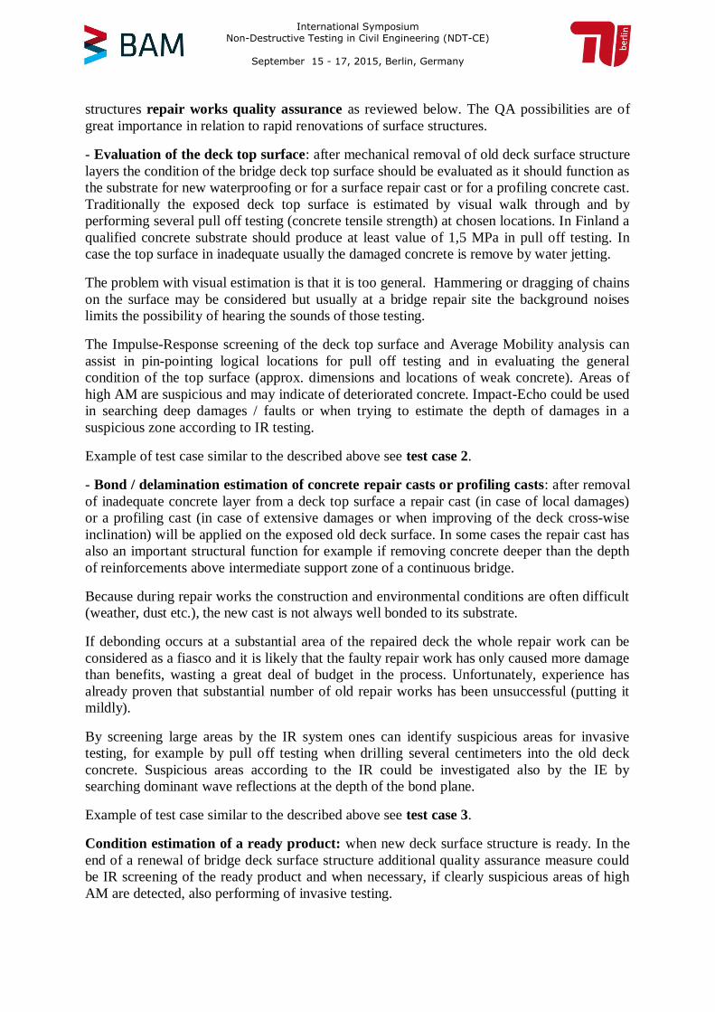
When analyzing the AM values one has to estimate the general mobility of the deck structureitself. For example, the cantilever zone of a deck should produce higher mobility values thanthe deck zone above a girder. Also areas of different thickness of surface structures will havedifferences in mobility (the thicker the less mobile).
Figure 7. Example of bridge deck mobility behaviour.Green arrow= relatively lowermobility zone.Red arrow= relatively higher mobility zone.
High AM values in evaluation of surface structure usually could indicate of:- Loose pavement / protective layers e.g. due to faulty execution or wear and tear.- Damaged pavement / protective layer, e.g. due to traffic loads or freeze-thaw.- Loose waterproofing from the protective layer- Loose waterproofing from it substrate (deck top surface), e.g. due to faulty execution, wearand tear or damaged substrate. This indication is the most severe to deck structure durabilitybecause it means that moisture and possibly de-icing salts might penetrate into deck structurecausing corrosion of reinforcements and thus weakens the structure. Also the repair of thiskind of damage is the most time and budget consuming.
Each of the indications may be a problem as good condition bridge surface structure shouldbe intact and its layers should be well bonded to each other.
The actual IR testing is done in a grid form, usually with intervals of 1 m from test points.The test points are marked by spray paint. Testing is performed in several investigation zonesusually of 20-50m2. Only rarely the whole bridge deck surface structure is screened,depending on the purpose of the test case in question.
Example of test case in the frame of a bridge special inspection, seetest case 1.
In addition to the usage of the IR in bridge special inspections the system is proven tobeneficial, sometimes together with the IE, in different phases of bridge deck surface
International Symposium Non-Destructive Testing in Civil Engineering (NDT-CE)
September 15 - 17, 2015, Berlin, Germany
structuresrepair works quality assurance as reviewed below. The QA possibilities are ofgreat importance in relation to rapid renovations of surface structures.
- Evaluation of the deck top surface: after mechanical removal of old deck surface structurelayers the condition of the bridge deck top surface should be evaluated as it should function asthe substrate for new waterproofing or for a surface repair cast or for a profiling concrete cast.Traditionally the exposed deck top surface is estimated by visual walk through and byperforming several pull off testing (concrete tensile strength) at chosen locations. In Finland aqualified concrete substrate should produce at least value of 1,5 MPa in pull off testing. Incase the top surface in inadequate usually the damaged concrete is remove by water jetting.
The problem with visual estimation is that it is too general. Hammering or dragging of chainson the surface may be considered but usually at a bridge repair site the background noiseslimits the possibility of hearing the sounds of those testing.
The Impulse-Response screening of the deck top surface and Average Mobility analysis canassist in pin-pointing logical locations for pull off testing and in evaluating the generalcondition of the top surface (approx. dimensions and locations of weak concrete). Areas ofhigh AM are suspicious and may indicate of deteriorated concrete. Impact-Echo could be usedin searching deep damages / faults or when trying to estimate the depth of damages in asuspicious zone according to IR testing.
Example of test case similar to the described above seetest case 2.
- Bond / delamination estimation of concrete repair casts or profiling casts: after removalof inadequate concrete layer from a deck top surface a repair cast (in case of local damages)or a profiling cast (in case of extensive damages or when improving of the deck cross-wiseinclination) will be applied on the exposed old deck surface. In some cases the repair cast hasalso an important structural function for example if removing concrete deeper than the depthof reinforcements above intermediate support zone of a continuous bridge.
Because during repair works the construction and environmental conditions are often difficult(weather, dust etc.), the new cast is not always well bonded to its substrate.
If debonding occurs at a substantial area of the repaired deck the whole repair work can beconsidered as a fiasco and it is likely that the faulty repair work has only caused more damagethan benefits, wasting a great deal of budget in the process. Unfortunately, experience hasalready proven that substantial number of old repair works has been unsuccessful (putting itmildly).
By screening large areas by the IR system ones can identify suspicious areas for invasivetesting, for example by pull off testing when drilling several centimeters into the old deckconcrete. Suspicious areas according to the IR could be investigated also by the IE bysearching dominant wave reflections at the depth of the bond plane.
Example of test case similar to the described above seetest case 3.
Condition estimation of a ready product: when new deck surface structure is ready. In theend of a renewal of bridge deck surface structure additional quality assurance measure couldbe IR screening of the ready product and when necessary, if clearly suspicious areas of highAM are detected, also performing of invasive testing.
International Symposium Non-Destructive Testing in Civil Engineering (NDT-CE)
September 15 - 17, 2015, Berlin, Germany
For the owner of the bridge this could mean additional quality assurance measure, i.e.additional indication that the renewed surface structure is intact. A logical time for performingthis kind of testing could be just before the end of the guarantee period given by the repairwork contactor for ensuring acceptance of a good quality product.
Example of test case similar to the described above seetest case 4.
In Finland Ramboll has frequently performed quality assurance NDT tasks in relation to rapidrenovations of surface structures when the assurance process should be fast andnondestructive as possible.
4. Example Test Cases
This paragraph will shortly review some selected test cases related to evaluation of bridgedeck surface structures by the mentioned NDT- techniques.
- Test case no. 1
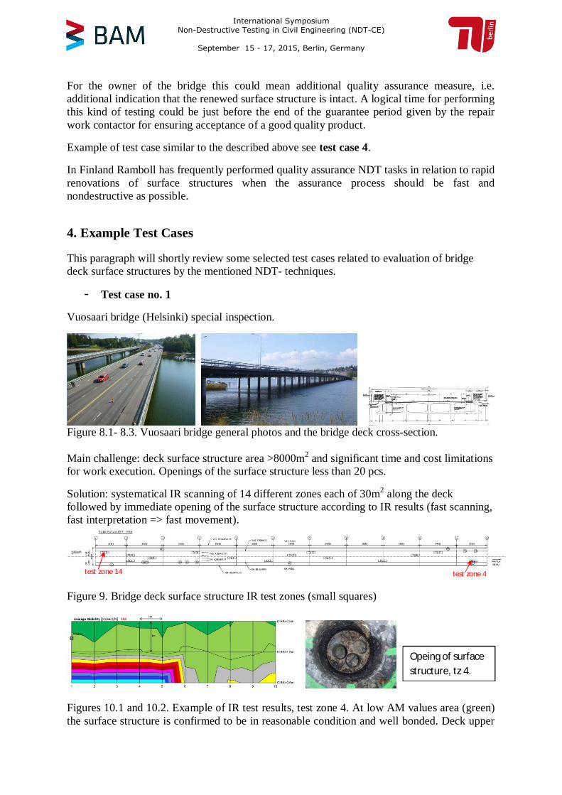
Vuosaari bridge (Helsinki) special inspection.
Figure 8.1- 8.3. Vuosaari bridge general photos and the bridge deck cross-section.
Main challenge: deck surface structure area >8000m2 and significant time and cost limitationsfor work execution. Openings of the surface structure less than 20 pcs.
Solution: systematical IR scanning of 14 different zones each of 30m2 along the deckfollowed by immediate opening of the surface structure according to IR results (fast scanning,fast interpretation => fast movement).
Figure 9. Bridge deck surface structure IR test zones (small squares)
Figures 10.1 and 10.2. Example of IR test results, test zone 4. At low AM values area (green)the surface structure is confirmed to be in reasonable condition and well bonded. Deck upper
Opeing of surfacestructure, tz 4.
test zone 4test zone 14
International Symposium Non-Destructive Testing in Civil Engineering (NDT-CE)
September 15 - 17, 2015, Berlin, Germany
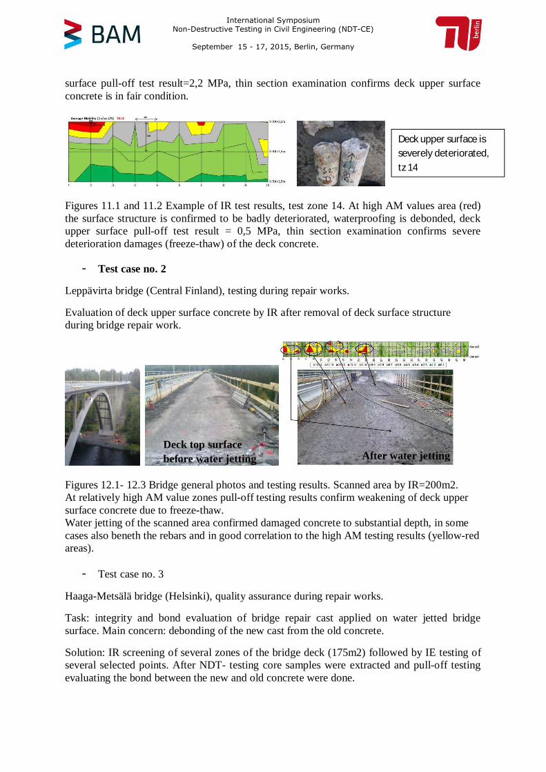
surface pull-off test result=2,2 MPa, thin section examination confirms deck upper surfaceconcrete is in fair condition.
Figures 11.1 and 11.2 Example of IR test results, test zone 14. At high AM values area (red)the surface structure is confirmed to be badly deteriorated, waterproofing is debonded, deckupper surface pull-off test result = 0,5 MPa, thin section examination confirms severedeterioration damages (freeze-thaw) of the deck concrete.
- Test case no. 2
Leppävirta bridge (Central Finland), testing during repair works.
Evaluation of deck upper surface concrete by IR after removal of deck surface structureduring bridge repair work.
Figures 12.1- 12.3 Bridge general photos and testing results. Scanned area by IR=200m2.At relatively high AM value zones pull-off testing results confirm weakening of deck uppersurface concrete due to freeze-thaw.Water jetting of the scanned area confirmed damaged concrete to substantial depth, in somecases also beneth the rebars and in good correlation to the high AM testing results (yellow-redareas).
- Test case no. 3
Haaga-Metsälä bridge (Helsinki), quality assurance during repair works.
Task: integrity and bond evaluation of bridge repair cast applied on water jetted bridgesurface. Main concern: debonding of the new cast from the old concrete.
Solution: IR screening of several zones of the bridge deck (175m2) followed by IE testing ofseveral selected points. After NDT- testing core samples were extracted and pull-off testingevaluating the bond between the new and old concrete were done.
Deck upper surface isseverely deteriorated,tz 14
Deck topsurfacebefore water jetting After water jetting
International Symposium Non-Destructive Testing in Civil Engineering (NDT-CE)
September 15 - 17, 2015, Berlin, Germany
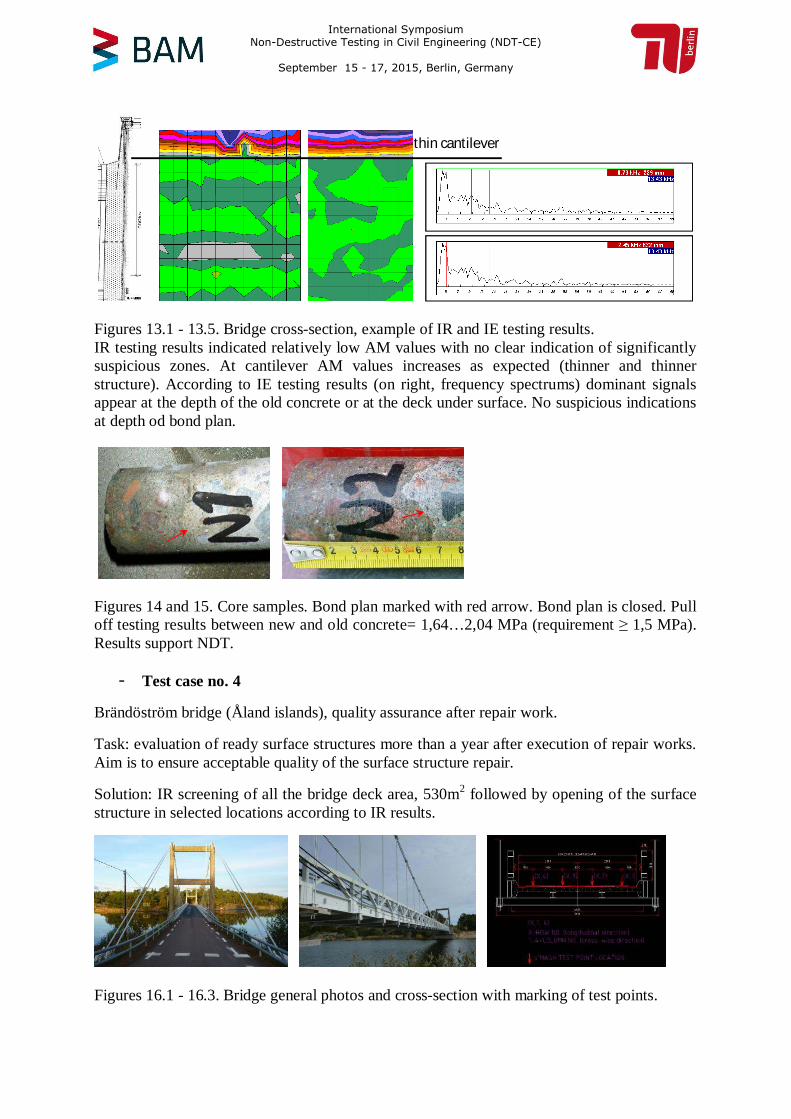
Figures 13.1 - 13.5. Bridge cross-section, example of IR and IE testing results.IR testing results indicated relatively low AM values with no clear indication of significantlysuspicious zones. At cantilever AM values increases as expected (thinner and thinnerstructure). According to IE testing results (on right, frequency spectrums) dominant signalsappear at the depth of the old concrete or at the deck under surface. No suspicious indicationsat depth od bond plan.
Figures 14 and 15. Core samples. Bond plan marked with red arrow. Bond plan is closed. Pulloff testing results between new and old concrete= 1,64…2,04 MPa (requirement ≥ 1,5 MPa).Results support NDT.
- Test case no. 4
Brändöström bridge (Åland islands), quality assurance after repair work.
Task: evaluation of ready surface structures more than a year after execution of repair works.Aim is to ensure acceptable quality of the surface structure repair.
Solution: IR screening of all the bridge deck area, 530m2 followed by opening of the surfacestructure in selected locations according to IR results.
Figures 16.1 - 16.3. Bridge general photos and cross-section with marking of test points.
thin cantilever
International Symposium Non-Destructive Testing in Civil Engineering (NDT-CE)
September 15 - 17, 2015, Berlin, Germany
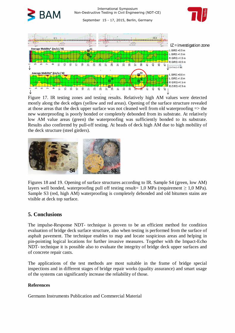
Figure 17. IR testing zones and testing results. Relatively high AM values were detectedmostly along the deck edges (yellow and red areas). Opening of the surface structure revealedat those areas that the deck upper surface was not cleaned well from old waterproofing => thenew waterproofing is poorly bonded or completely debonded from its substrate. At relativelylow AM value areas (green) the waterproofing was sufficiently bonded to its substrate.Results also confiremd by pull-off testing. At heads of deck high AM due to high mobility ofthe deck structure (steel girders).
Figures 18 and 19. Opening of surface structures according to IR. Sample S4 (green, low AM)layers well bonded, waterproofing pull off testing result= 1,0 MPa (requirement ≥ 1,0 MPa).Sample S3 (red, high AM) waterproofing is completely debonded and old bitumen stains arevisible at deck top surface.
5. Conclusions
The impulse-Response NDT- technique is proven to be an efficient method for conditionevaluation of bridge deck surface structure, also when testing is performed from the surface ofasphalt pavement. The technique enables to map and locate suspicious areas and helping inpin-pointing logical locations for further invasive measures. Together with the Impact-EchoNDT- technique it is possible also to evaluate the integrity of bridge deck upper surfaces andof concrete repair casts.
The applications of the test methods are most suitable in the frame of bridge specialinspections and in different stages of bridge repair works (quality assurance) and smart usageof the systems can significantly increase the reliability of those.
References
Germann Instruments Publication and Commercial Material
IZ = investigation zone
S3S4
International Symposium Non-Destructive Testing in Civil Engineering (NDT-CE)
September 15 - 17, 2015, Berlin, Germany