condenser and condensing units - aaon · condenser and condensing units installation, operation,...
TRANSCRIPT
CF Series
Condenser and Condensing Units
Installation Operation
amp Maintenance
If the information in this manual is not followed exactly a fire or explosion may result causing property damage personal injury or loss of life
WARNING
QUALIFIED INSTALLER
Improper installation adjustment alteration service or maintenance can cause property damage personal injury or loss of life Installation and service must be performed by a Factory Trained Service Technician A copy of this IOM should be kept with the unit
WARNING
FOR YOUR SAFETY
Do not store or use gasoline or other flammable vapors and liquids in the vicinity of this or any other appliance
WARNING
2
Table of Contents
AAON CF Series Features and Options Introduction 5 Safety 6 CF Series Feature String Nomenclature 11 General Information 15
Codes and Ordinances 15 Receiving Unit 15 Storage 16 Wiring Diagrams 17 General Maintenance 17
Installation 18 Forklifting the Unit 18
Lifting the Unit 19 Locating the Unit 19
Mounting Isolation 20 Access Doors 20
Standard Evacuation Instructions 20 Low Ambient amp Modulating Reheat System Evacuation Instructions 21 Adjusting Refrigerant Charge 22
Low Ambient Operation 27 Fan Cycling Low Ambient 27
Variable Speed Low Ambient 27 Flooded Condenser Low Ambient 27
LAC Valve 28 Refrigerant Piping 29
Determining Refrigerant Line Size 29 Liquid Line 30 Suction Line 31
Discharge Line 33 Hot Gas Bypass Line 35
Hot Gas Reheat 36 Electrical 37
Startup 39 Compressor Operation 39 Variable Capacity Compressor Controller 40
Low Voltage Terminals 40 High Voltage Terminals 40
Compressor Lockouts 42 Maintenance 43
General 43 Compressors 43 Refrigerant Filter Driers 43 Lubrication 44
3
Condenser Tube Inspection 44 Maintenance Recommendations 44 E-Coated Coil Cleaning 45 Service 48
Replacement Parts 48 AAON Technical Support 48
Split System Refrigerant Piping Diagrams 49
Index of Tables and Figures
Tables
Table 1 ndashClearances for Proper Operation 19 Table 2 ndash Clearances for Coil Pull 19
Table 3 - Acceptable Refrigeration Circuit Values 24
Table 4 ndash Charge to Flood Condenser Coil for Ambient Above 70degF 26 Table 5 ndash Charge to Flood Condenser Coil for Ambient Below 70degF 26 Table 6 - Nameplate Voltage Markings 37
Table 7 - Demand Signal vs Compressor Capacity Modulation 41 Table 8 - Thermistor Temperature vs Resistance Values 42
Table 9 - Max Filter Drier Pressure Drops 43 Table 10 - R-410A Refrigerant Temperature-Pressure Chart 44
Figures
Figure 1 - Forklifting a CF Series A Cabinet 18
Figure 2 - Forklifting a CF Series B and C Cabinet 18 Figure 3 ndash Lifting Details and Orientation of a CF Series 9-70 ton Condensing Unit 19 Figure 4 - Orientation of Series 2-7 ton Condensing Unit 19
Figure 5 ndash CU evacuation connections 21 Figure 6 ndash CU evacuation connections 22
Figure 7 - Adjustable Fan Cycling Switch 27 Figure 8 ndash LAC Piping Example 28 Figure 9 - Double Suction Riser Construction 32 Figure 10 ndash Heat Pump Piping Schematic of Cooling Mode in Double Riser 34 Figure 11 ndash Heat Pump Piping Schematic of Heating Mode in Double Riser 34
Figure 12 ndash Oil Return Line 36 Figure 13 - Variable Capacity Compressor Controller 40
Figure 14 - Compressor Controller Flash Code Details 41 Figure 15 - Adjustable compressor lockout 42 Figure 16 - Ambient sensor cover 42 Figure 17 - AC Split System Piping Suction Down 49 Figure 18 - AC Split System Piping Suction Up 50
Figure 19 - AC with LAC Split System Piping Suction Down 51 Figure 20 - AC with LAC Split System Piping Suction Up 52 Figure 21 - AC with Modulating Hot Gas Reheat Split System Piping Suction Down 53
4
Figure 22 - AC with Modulating Hot Gas Reheat Split System Piping Suction Up 54 Figure 23 - AC with Modulating Hot Gas Reheat Split + LAC System Piping Suction Down 55 Figure 24 - AC with Modulating Hot Gas Reheat Split + LAC System Piping Suction Up 56 Figure 25 - AC with Hot Gas Bypass Split System Piping Suction Down 57
Figure 26 - AC with Hot Gas Bypass Split System Piping Suction Up 58 Figure 27 - AC with Hot Gas Bypass + LAC Split System Piping Suction Down 59 Figure 28 - AC with Hot Gas Bypass + LAC Split System Piping Suction Up 60 Figure 29 - AC with Modulating Hot Gas Reheat and Hot Gas Bypass Split System Piping
Suction Down 61
Figure 30 - AC with Modulating Hot Gas Reheat and Hot Gas Bypass Split System Piping
Suction Up 62 Figure 31 - AC with Modulating Hot Gas Reheat and Hot Gas Bypass + LAC Split System
Piping Suction Down 63
Figure 32 - AC with Modulating Hot Gas Reheat and Hot Gas Bypass + LAC Split System
Piping Suction Up 64
Figure 33 - Heat Pump Split System Piping Suction Down 65 Figure 34 - Heat Pump Split System Piping Suction Up 66
Figure 35 - Heat Pump with Modulating Hot Gas Reheat Split System Piping Suction Down 67 Figure 36 - Heat Pump with Modulating Hot Gas Reheat Split System Piping Suction Up 68 Figure 37 - Heat Pump with Hot Gas Bypass Split System Piping Suction Down 69
Figure 38 - Heat Pump with Hot Gas Bypass Split System Piping Suction Up 70 Figure 39 ndash Heat Pump with Modulating Hot Gas Reheat and Hot Gas Bypass Split System
Piping Suction Down 71 Figure 40 ndash Heat Pump with Modulating Hot Gas Reheat and Hot Gas Bypass Split System
Piping Suction Up 72
V45040 Rev A 190709
(ACP J00424)
5
AAON CF Series Features and Options Introduction
Energy Efficiency
bull Two-Stage 10-100 Variable Capacity
or Tandem R-410A Scroll Compressors
bull Air-Source Heat Pump
bull VFD Controlled ECM Driven and
ECM Low Sound Condenser Fans
Humidity Control bull Modulating Hot Gas Reheat
bull Makeup Air Applications up to 100
Outside Air
Safety bull Phase and Brownout Protection
bull Single Point Non-Fused Disconnect
Power Switch
bull Automatic Low Pressure and Manual
Reset High Pressure Safety Cut-outs
bull Adjustable Compressor Lockout
Installation and Maintenance bull Isolated Controls and Compressor
Compartment
bull Access Doors with Full Length Stainless
Steel Piano Hinges
bull Molded Lockable Handles
bull Color-Coded Wiring Diagrams
bull Run Test Report and Installation Manual
Included in Controls Compartment
bull Factory Installed Convenience Outlet
bull Service Access Lights
bull Remote StartStop Terminals
bull Liquid Line Sight Glass
bull Compressor Isolation Valves
System Integration bull Complete Split System with AAON DX
Air Handling Units
bull Remote Air-Cooled Condenser Option
bull Labeled Split System Piping Stub Outs
with Shut-Off Valves
bull Flooded Condenser 0degF Low Ambient
Controls
bull Terminal Block for Thermostat with
Isolation Relays
bull Constant Air Volume (CAV) Makeup
Air (MUA) Variable Air Volume
(VAV) and Single Zone Variable Air
Volume (SZ VAV)
Environmentally Friendly bull R-410A Refrigerant
Extended Life bull Optional 5 Year Compressor Warranty
bull G90 Galvanized Steel Construction
bull 2500 Hour Salt Spray Tested Exterior
Corrosion Protection
bull 10000 Hour Salt Spray Tested Polymer
E-Coated Condenser Coils
bull Copper Fin and Stainless Steel Casing
Coils
bull Condenser Coil Guards
bull Custom Color Paint Options
6
Safety
Attention should be paid to the following statements
NOTE - Notes are intended to clarify the unit installation operation and maintenance
CAUTION - Caution statements are given to prevent actions that may result in equipment
damage property damage or personal injury
WARNING - Warning statements are given to prevent actions that could result in
equipment damage property damage personal injury or death
DANGER - Danger statements are given to prevent actions that will result in equipment
damage property damage severe personal injury or death
QUALIFIED INSTALLER Improper installation adjustment alteration service or maintenance can cause property damage personal injury or loss of life Startup and service must be performed by a Factory Trained Service Technician A copy of this IOM should be kept with the unit
WARNING
ELECTRIC SHOCK Electric shock hazard Before servicing shut off all electrical power to the unit including remote disconnects to avoid shock hazard or injury from rotating parts Follow proper Lockout-Tagout procedures
WARNING
ELECTRIC SHOCK FIRE OR EXPLOSION HAZARD Failure to follow safety warnings exactly could result in dangerous operation serious injury death or property damage Improper servicing could result in dangerous operation serious injury death or property damage When servicing controls label all
wires prior to disconnecting Reconnect wires correctly
Verify proper operation after servicing Secure all doors with key-lock or nut and bolt
WARNING
7
ROTATING COMPONENTS Unit contains fans with moving parts that can cause serious injury Do not remove grill containing fans until the power to the unit has been disconnected and fan has stopped rotating
WARNING
LIVE ELECTRICAL During installation testing servicing and troubleshooting of the equipment it may be necessary to work with live electrical components Only a qualified licensed electrician or individual properly trained in handling live electrical components shall perform these tasks Standard NFPA-70E an OSHA regulation requiring an Arc Flash Boundary to be field established and marked for identification of where appropriate Personal Protective Equipment (PPE) be worn should be followed
WARNING
FIRE EXPLOSION OR CARBON MONOXIDE POISONING HAZARD Failure to replace proper controls could result in fire explosion or carbon monoxide poisoning Failure to follow safety warnings exactly could result in serious injury death or property damage Do not store or use gasoline or other flammable vapors and liquids in the vicinity of this appliance
WARNING
GROUNDING REQUIRED All field installed wiring must be completed by qualified personnel Field installed wiring must comply with NECCEC local and state electrical code requirements Failure to follow code requirements could result in serious injury or death Provide proper unit ground in accordance with these code requirements
WARNING
VARIABLE FREQUENCY DRIVES
Do not leave VFDs unattended in hand mode or manual bypass Damage to personnel or equipment can occur if left unattended When in hand mode or manual bypass mode VFDs will not respond to controls or alarms
WARNING
8
LEAK TESTING
Do not use oxygen acetylene or air in place of refrigerant and dry nitrogen for leak testing A violent explosion may result causing injury or death
WARNING
VARIABLE FREQUENCY DRIVES
Electric motor over-current protection and overload protection may be a function of the Variable Frequency Drive to which the motors are wired Never defeat the VFD motor overload feature The overload ampere setting must not exceed 115 of the electric motors FLA rating as shown on the motor nameplate
CAUTION
PVC PIPING
PVC (Polyvinyl Chloride) and CPVC (Chlorinated Polyvinyl Chloride) are vulnerable to attack by certain chemicals Polyolester (POE) oils used with R-410A and other refrigerants even in trace amounts in a PVC or CPVC piping system will result in stress cracking of the piping and fittings and complete piping system failure
CAUTION
3-PHASE ROTATION
Rotation must be checked on all MOTORS AND COMPRESSORS of 3 phase units at startup by a qualified service technician Scroll compressors are directional and can be damaged if rotated in the wrong direction Compressor rotation must be checked using suction and discharge gauges Fan motor rotation should be checked for proper operation Alterations should only be made at the unit power connection
CAUTION
UNIT HANDLING To prevent injury or death lifting equipment capacity shall exceed unit weight by an adequate safety factor Always test-lift unit not more than 24 inches high to verify proper center of gravity lift point to avoid unit damage injury or death
WARNING
DOOR LATCHES
Door compartments containing hazardous voltage or rotating parts are equipped with door latches that allow locks Door latches are shipped with a nut and bolt requiring tooled access If the shipping hardware is not replaced with a pad lock always re-install the nut and bolt after closing the door to maintain tooled access
CAUTION
9
ENCLOSED AREA
Do not work in an enclosed area where refrigerant or nitrogen gases may be leaking A sufficient quantity of vapors may be present and cause
injury or death
WARNING
COMPRESSOR LUBRICANT
Polyolester (POE) and Polyvinylether (PVE) oils are two types of lubricants used in hydrofluorocarbon (HFC) refrigeration systems Refer to the compressor label for the proper compressor lubricant type
CAUTION
COIL CLEANERS
To prevent damage to the unit do not use acidic chemical coil cleaners Do not use alkaline chemical coil cleaners with a pH value greater than 85 after mixing without first using an aluminum corrosion inhibitor in the cleaning solution
CAUTION
COIL CLEANERS
Some chemical coil cleaning compounds are caustic or toxic Use these substances only in accordance with the manufacturerrsquos usage instructions Failure to follow instructions may result in equipment damage injury or death
WARNING
COIL CLEANING
Do not clean DX refrigerant coils with hot water or steam The use of hot water or steam on refrigerant coils will cause high pressure inside the coil tubing and damage to the coil
CAUTION
CONVENIENCE OUTLETS
Factory installed convenience outlets are not intended for use while the unit is operating
WARNING
10
1 Startup and service must be performed by
a Factory Trained Service Technician
2 The unit is for outdoor use only See
General Information section for more
information
3 Every unit has a unique equipment
nameplate with electrical operational
and unit clearance specifications
Always refer to the unit nameplate for
specific ratings unique to the model
purchased
4 READ THE ENTIRE INSTALLATION
OPERATION AND MAINTENANCE
MANUAL OTHER IMPORTANT
SAFETY PRECAUTIONS ARE
PROVIDED THROUGHOUT THIS
MANUAL
5 Keep this manual and all literature
safeguarded near or on the unit
COMPRESSOR CYCLING
5 MINUTE MINIMUM OFF TIME To prevent motor overheating compressors must cycle off for a minimum of 5 minutes
5 MINUTE MINIMUM ON TIME To maintain the proper oil level compressors must cycle on for a minimum of 5 minutes The cycle rate must not exceed 6 starts per hour
WARNING
CF Series Feature String Nomenclature
Model Options Unit Feature Options G
EN
MJ
RE
V
SIZ
E
SE
RIE
S
MN
RE
V
VL
T
A1
A2
A3
A4
A5
1
2A
2B
3A
3B
4
5
6A
6B
6C
7
8A
8B
8C
8D
9
10
11
12
13
14
15
CF A - 015 - B - A - 3 - D C 0 0 K 0 - A 0 - E 0 - C 0 - A N 0 - B - D E 0 0 - 0 0 A 0 E 0 0
0 0 0 0 0 D B
16
17
18
19
20
21
22
11
CF Series Feature String Nomenclature
MODEL OPTIONS Series and Generation
CF
Major Revision
A
Unit Size
002 = 2 ton Capacity
003 = 3 ton Capacity
004 = 4 ton Capacity
005 = 5 ton Capacity
006 = 6 ton Capacity
007 = 7 ton Capacity
009 = 9 ton Capacity
011 = 11 ton Capacity
013 = 13 ton Capacity
015 = 15 ton Capacity
016 = 16 ton Capacity
018 = 18 ton Capacity
020 = 20 ton Capacity
025 = 25 ton Capacity
026 = 26 ton Capacity
030 = 30 ton Capacity
031 = 31 ton Capacity
040 = 40 ton Capacity
050 = 50 ton Capacity
060 = 60 ton Capacity
070 = 70 ton Capacity
Series
A = 2-7 ton units
B = 9-15 ton units
C = 16-25 amp 30 ton units
D = 26 amp 31-70 ton units
Minor Revision
A
Voltage
1 = 230V1Φ60Hz
2 = 230V3Φ60Hz
3 = 460V3Φ60Hz
4 = 575V3Φ60Hz
8 = 208V3Φ60Hz
9 = 208V1Φ60Hz
A1 Compressor Style
0 = Air-Cooled Condenser - No Compressors
(1 Circuit)
A = R-410A Scroll Compressors
B = R-410A Two Step Capacity Scroll Compressors
D = R-410A Variable Capacity Scroll Compressors
E = R-410A Tandem Scroll Compressors
G = R-410A Tandem Variable Capacity Scroll
Compressors
P = Air-Cooled Condenser - No Compressors
(2 Circuits)
Q = Air-Cooled Condenser - No Compressors
(4 Circuits)
A2 Condenser Style
C = Air-Cooled Condenser
J = Air-Source Heat Pump
A3 Configuration
0 = Standard
A4 Coating
0 = Standard
E = Polymer E-Coated Condenser Coil
G = Copper Fin + Stainless Steel Casing - Condenser
Coil
A5 Staging
0 = No Cooling
G = 1 OnOff Refrigeration System
H = 1 Variable Capacity Refrigeration System
J = 2 OnOff Refrigeration Systems
K = 1 Variable Capacity Refrigeration System + 1
OnOff Refrigeration System
L = 2 Variable Capacity Refrigeration System
R = 4 OnOff Refrigeration Systems
T = 2 Variable Capacity Refrigeration Systems + 2
OnOff Refrigeration Systems
U = 4 Variable Capacity Refrigeration Systems
CF Series Feature String Nomenclature
Model Options Unit Feature Options G
EN
MJR
EV
SIZ
E
SE
RIE
S
MN
RE
V
VL
T
A1
A2
A3
A4
A5
1
2A
2B
3A
3B
4
5
6A
6B
6C
7
8A
8B
8C
8D
9
10
11
12
13
14
15
CF A - 015 - B - A - 3 - D C 0 0 K 0 - A 0 - E 0 - C 0 - A N 0 - B - D E 0 0 - 0 0 A 0 E 0 0
0 0 0 0 0 D B
16
17
18
19
20
21
22
12
UNIT FEATURE OPTIONS 1 Unit Orientation
0 = Vertical Condenser Discharge - Standard Access
A = Horizontal Condenser Discharge - Standard
Access
2A Refrigeration Control
0 = Standard
A = 5 Minute Compressor Off Timer + 20 Second
Compressor Stage Delay
C = Adjustable Fan Cycling
D = Adjustable Compressor Lockout
G = Option A + Adjustable Fan Cycling
H = Option A + Adjustable Compressor Lockout
M = Adjustable Fan Cycling + Adjustable
Compressor Lockout
W = Option A + Adjustable Fan Cycling +
Adjustable Compressor Lockout
2B Blank
0 = Standard
3A Refrigeration Options
0 = Standard
A = Hot Gas Bypass Lead Stage [HGB]
B = HGB Lead + HGB Lag
D = Hot Gas Bypass Non-Variable Capacity
Refrigeration Systems [HGBNV]
E = Modulating Hot Gas Reheat [MHGR]
H = HGB + MHGR
J = HGB Lead + HGB Lag + MHGR
L = HGBNV + MHGR
3B Blank
0 = Standard
4 Refrigeration Accessories
0 = Standard
A = Sight Glass
B = Compressor Isolation Valves
C = Options A + B
D = Flooded Condenser 0degF Low Ambient Controls ndash
One Circuit
E = Options A + D
F = Options B + D
G = Options A + B + D
H = Flooded Condenser 0degF Low Ambient Controls-
Two Circuits
J = Options A + H
K = Options B + H
L = Options A + B + H
R = Flooded Condenser 0degF Low Ambient Controls ndash
Four Circuits
S = Options A + R
T = Options B + R
U = Options A + B + R
5 Blank
0 = Standard
6A Unit Disconnect Type
0 = Single Point Power Block
A = Single Point Power Non-Fused Disconnect
6B Disconnect 1 Size
0 = Standard
N = 100 amps
R = 150 amps
V = 250 amps
Z = 400 amps
6C Blank
0 = Standard
CF Series Feature String Nomenclature
Model Options Unit Feature Options
GE
N
MJR
EV
SIZ
E
SE
RIE
S
MN
RE
V
VL
T
A1
A2
A3
A4
A5
1
2A
2B
3A
3B
4
5
6A
6B
6C
7
8A
8B
8
C
8D
9
10
11
12
13
14
15
CF A - 015 - B - 0 - 3 - D C 0 0 K 0 - A 0 - E 0 - C 0 - A N 0 - B - D C 0 0 - 0 0 A 0 E 0 0 0 0 0 0 0 D B
16
17
18
19
20
21
22
13
7 Accessories
0 = Standard
B = Phase amp Brown Out Protection
D = Suction Pressure Transducer on Each
Refrigeration Circuit
E = Compressor Sound Blanket
L = Options B + D
M = Options B + E
Q = Options D + E
1 = Options B + D + E
8A Control Sequence
A = Terminal Block for Thermostat w Isolation
Relays
D = VAV Unit Controller - VAV Cool + CAV Heat
E = CAV Unit Controller
F = Makeup Air Unit Controller - CAV Cool + CAV
Heat
H = Constant Volume HP Unit Controller - CAV
Cool + CAV Heat
J = Makeup Air HP Unit Controller - CAV Cool +
CAV Heat
N = Field Installed DDC Controls by Others with
Isolation Relays
8B Control Suppliers
0 = Standard
E = Orion VCC-X (Main Controller in Air Handling
Unit)
H = AAON Touchscreen Controller (Main Controller
in Air Handling Unit)
8C Control Supplier Options
0 = Standard
8D BMS Connection amp Diagnostics
0 = Standard
9 Blank
0 = Standard
10 Blank
0 = Standard
11 Maintenance Accessories
0 = Standard
A = Factory Wired 115VAC Convenience Outlet
B = Field Wired 115VAC Convenience Outlet
C = Service Lights
E = Remote Unit StartStop Terminals
F = Options A + C
H = Options A + E
J = Options B + C
L = Options B + E
N = Options C + E
R = Options A + C + E
U = Options B + C + E
12 Code Options
0 = Standard ETL USA Listing
B = ETL USA + Canada Listing
13 Air-Cooled Condenser Accessories
0 = Standard
A = Condenser Coil Guard
C = ECM Condenser Fan Head Pressure Control
E = VFD Condenser Fan Head Pressure Control
G = Options A + C
J = Options A + E
N = ECM Condenser Fan Head Pressure Control +
Low Sound Condenser Fan
S = Options A + N
14 Blank
0 = Standard
15 Blank
0 = Standard
16 Electrical Options
0 = Standard
17 Shipping Options
0 = Standard
A = Crating
B = Export Crating
CF Series Feature String Nomenclature
Model Options Unit Feature Options G
EN
MJR
EV
SIZ
E
SE
RIE
S
MN
RE
V
VL
T
A1
A2
A3
A4
A5
1
2A
2B
3A
3B
4
5
6A
6B
6C
7
8A
8B
8C
8D
9
10
11
12
13
14
15
CF A - 015 - B - A - 3 - D C 0 0 K 0 - A 0 - E 0 - C 0 - A N 0 - B - D E 0 0 - 0 0 A 0 E 0 0
0 0 0 0 0 D B 1
6
17
18
19
20
21
22
14
18 Blank
0 = Standard
19 Blank
0 = Standard
20 Cabinet Material
0 = Galvanized Steel Cabinet
21 Warranty
0 = Standard
D = Compressor Warranty - Years 2-5
22 Type
B = Premium AAON Gray Paint Exterior
E = Premium AAON Gray Paint Ext + Shrink Wrap
X = SPA + Premium AAON Gray Paint Exterior
1 = SPA + Premium AAON Gray Paint Exterior +
Shrink Wrap
15
General Information
AAON CF Series air-cooled condensers and
condensing units have been designed for
outdoor use only They are factory
assembled wired charged and run-tested
Codes and Ordinances
CF Series units have been tested and
certified by ETL in accordance with UL
Safety Standard 1995CSA C222 No 236
System should be sized in accordance with
the American Society of Heating
Refrigeration and Air Conditioning
Engineers Handbook
Installation of CF Series units must conform
to the ICC standards of the International
Mechanical Code the International Building
Code and local building plumbing and
electrical codes All appliances must be
electrically grounded in accordance with
local codes or in the absence of local codes
the current National Electric Code
ANSINFPA 70 or the current Canadian
Electrical Code CSA C221
Receiving Unit
When received the unit should be checked
for damage that might have occurred in
transit If damage is found it should be noted
on the carrierrsquos freight bill A request for
inspection by carrierrsquos agent should be made
in writing at once Nameplate should be
checked to ensure the correct model sizes and
voltages have been received to match the job
requirements
If repairs must be made to damaged goods
then the factory should be notified before any
repair action is taken in order to protect the
warranty Certain equipment alteration
repair and manipulation of equipment
without the manufacturerrsquos consent may void
the product warranty Contact AAON
Technical Support for assistance with
handling damaged goods repairs and freight
claims (918) 382-6450
SHARP EDGES
Coils and sheet metal surfaces present sharp edges and care must be taken when working with equipment
WARNING
QUALIFIED INSTALLER
Improper installation adjustment alteration service or maintenance can cause property damage personal injury or loss of life Installation and service must be performed by a Factory Trained Service Technician
WARNING
Failure to observe the following instructions will result in premature failure of your system and possible voiding of the warranty
WARNING
16
Storage
If installation will not occur immediately
following delivery store equipment in a dry
protected area away from construction traffic
and in the proper orientation as marked on the
packaging with all internal packaging in
place Secure all loose-shipped items
Failure to observe the following instructions
will result in premature failure of your
system and possible voiding of the warranty
Never turn off the main power supply to the
unit except for complete shutdown When
power is cut off from the unit any
compressors using crankcase heaters cannot
prevent refrigerant migration This means the
compressor will cool down and liquid
refrigerant may accumulate in the
compressor The compressor is designed to
pump refrigerant gas and damage may occur
if liquid enters the compressor when power is
restored
Before unit operation the main power switch
must be turned on for at least twenty-four
hours for units with compressor crankcase
heaters This will give the crankcase heater
time to clear any liquid accumulation out of
the compressor before it is required to run
Always control the system from the control
panel never at the main power supply (except
for emergency or for complete shutdown of
the system)
CLEAN AIR ACT
The Clean Air Act of 1990 bans the intentional venting of refrigerant as of July 1 1992 Approved methods of recovery recycling or reclaiming must be followed
CAUTION
CRANKCASE HEATER OPERATION
Units are equipped with compressor crankcase heaters which should be energized at least 24 hours prior to cooling operation to clear any liquid refrigerant from the compressors
CAUTION
3-PHASE ROTATION
Rotation must be checked on all MOTORS AND COMPRESSORS of three phase units All motors to include and not be limited to pump motors and condenser fan motors should all be checked by a qualified service technician at startup and any wiring alteration should only be made at the unit power connection
CAUTION
17
The standard compressors must be on a
minimum of 5 minutes and off for a minimum
of 5 minutes The cycle rate must be no more
than 6 starts per hour
The variable capacity compressors must be
on a minimum of 3 minutes and off for a
minimum of 3 minutes The cycle rate must
be no more than 6 starts per hour
The compressor life will be seriously
shortened by reduced lubrication and the
pumping of excessive amounts of liquid oil
and liquid refrigerant
Wiring Diagrams
A complete set of unit specific wiring
diagram in point-to-point form is laminated
in plastic and located inside the control
compartment door
General Maintenance
When the initial startup is made and on a
periodic schedule during operation it is
necessary to perform routine service checks
on the performance of the condensing unit
This includes reading and recording suction
pressures and checking for normal sub-
cooling and superheat
COMPRESSOR ROTATION
Scroll compressors are directional and will be damaged by operation in the wrong direction Low pressure switches on compressors have been disconnected after factory testing Rotation should be checked by a qualified service technician at startup using suction and discharge pressure gauges and any wiring alteration should only be made at the unit power connection
COMPRESSOR CYCLING
5 MINUTE MINIMUM OFF TIME To prevent motor overheating compressors must cycle off for a minimum of 5 minutes
5 MINUTE MINIMUM ON TIME To maintain the proper oil level compressors must cycle on for a minimum of 5 minutes The cycle rate must not exceed 6 starts per hour
WARNING
CAUTION
18
Installation
Forklifting the Unit
CF Series condensing unit sizes 2-25 amp 30
tons can be lifted using a forklift 2-7 ton
units must have forks at least 48rdquo in length
9-25 amp 30 ton units must have forks 72rdquo in
length or the forks must have 72rdquo fork
extensions Standard units can be lifted from
all sides except the condenser coil side CF
Series condensing unit sizes 26 amp 31-70 tons
cannot be lifted using a forklift They can be
lifted as shown in Figure 3
Forks must be perpendicular to the unit and
they must be in far enough that the back of
the forks are no more than 6rdquo away from the
edge of the unit
Figure 1 - Forklifting a CF Series A Cabinet
Figure 2 - Forklifting a CF Series B and C
Cabinet
FORKLIFTING 2-7 TON UNITS
Forks or Fork Extensions must be at least 48rdquo in length
CAUTION
FORKLIFTING 9-25 amp 30 TON UNITS
Forks or Fork Extensions must be at least 72rdquo in length
CAUTION
19
Lifting the Unit
If cables or chains are used to hoist the unit
they must be the same length Minimum
cable length is 99rdquo for CF Series 9-70 ton
units CF Series 2-7 ton units do not include
factory installed lifting lugs and should be
lifted by forklift only Care should be taken
to prevent damage to the cabinet coils and
condenser fans
Before lifting unit be sure that all shipping
material has been removed from unit Secure
hooks and cables at all lifting points lugs
provided on the unit
Figure 3 ndash Lifting Details and Orientation of
a CF Series 9-70 ton Condensing Unit
Locating the Unit
The CF Series condenser and condensing unit
is designed for outdoor applications and
mounting at ground level or on a rooftop It
must be placed on a level and solid
foundation that has been prepared to support
its weight When installed at ground level a
one-piece concrete slab should be used with
footings that extend below the frost line Also
with ground level installation care must be
taken to protect the coil fins from damage due
to vandalism or other causes
The first clearance table below gives the
clearance values for proper unit operation
The second clearance table gives the
clearance necessary for removing the coil
without disassembling a large part of the
condensing unit For ease of removing the
condenser coil use the second table
clearances for the right hand side of the unit
Table 1 ndashClearances for Proper Operation
Location Unit Size
2-7 tons 9-70 tons
Front -
(Controls
Side)
Unobstructed 36rdquo
Left Side 6rdquo 30rdquo
Right Side 6rdquo 36rdquo
Top 3rdquo Unobstructed
Back 18rdquo 6rdquo
Table 2 ndash Clearances for Coil Pull
Unit Size Right Hand Side
2-7 tons 42rdquo
9-15 tons 42rdquo
16-25 amp 30 tons 54rdquo
26 amp 31-70 tons 66rdquo
Figure 4 - Orientation of Series 2-7 ton
Condensing Unit
20
The placement relative to the building air
intakes and other structures must be carefully
selected Airflow to and from the condenser
or condensing unit must not be restricted to
prevent a decrease in performance and
efficiency
The installation position for 9-70 ton units
must provide at least 30rdquo of left and right side
clearance for proper airflow to the condenser
coils When units are mounted adjacent to
each other the minimum right and left side
clearance required between the units is 60rdquo or
5 feet Similarly when 2-7 ton units are
mounted adjacent to each other the minimum
clearance required between the back side of
the units is 36rdquo or 3 feet
Units should not be installed in an enclosure
or pit that is deeper than the height of the unit
When recessed installation is necessary the
clearance to maintain proper airflow is at
least 5 feet (3 feet for 2-7tons)
CF Series condensers and condensing units
that have a vertical air discharge must have
no obstruction above the equipment Do not
place the unit under an overhang CF Series
condensers and condensing units that have a
horizontal discharge must have no
obstruction in front of the unit
For proper unit operation the immediate area
around condenser must remain free of debris
that may be drawn in and obstruct airflow in
the condensing section
Consideration must be given to obstruction
caused by snow accumulation when placing
the unit
Mounting Isolation
For roof mounted applications or anytime
vibration transmission is a factor vibration
isolators may be used
Access Doors
Access doors are provided to the compressor
and electrical compartment
Standard Evacuation Instructions
Proper system evacuation is critical to
remove moisture and non-condensables from
the system before charging the system with
refrigerant A newly installed AAON
condensing unit has already been evacuated
and charged with some refrigerant at the
factory When evacuating a new system
keep the condensing unit service valves
closed and evacuate the suction and liquid
lines and the air handling unit If the entire
system must be evacuated use the following
procedure to ensure the entire system is
pulled into a good vacuum
1 System evacuation should be
performed anytime a system is open to
atmospheric pressure The POE oils
used with R-410A are extremely
hydroscopic in nature and immediately
begin pulling in moisture once the
system is opened to the atmosphere
2 Before starting to evacuate the
system you MUST ensure that there are
no leaks by pressurizing the system with
PVC PIPING
PVC (Polyvinyl Chloride) and CPVC (Chlorinated Polyvinyl Chloride) are vulnerable to attack by certain chemicals Polyolester (POE) oils used with R-410A and other refrigerants even in trace amounts in a PVC or CPVC piping system will result in stress cracking of the piping and fittings and complete piping system failure
CAUTION
21
400 psig of dry nitrogen and verifying no
pressure loss after one hour
3 Four valve manifold gauge sets are
more effective than standard manifold
gauge sets due to the extra hose port in
combination with a 38rsquorsquo evacuation
port The larger diameter evacuation port
will expedite system evacuation
4 The manifold set should be connected
to the condensing unit with one hose on
the suction line service valve one hose
on the liquid line service valve and if an
extra Schrader valve is field installed on
the suction line connect a third hose (not
shown) The vacuum pump should be
connected to the manifold set using a
38rdquo vacuum rated hose Figure 5 shows
two circuits Both circuits must be
evacuated separately
Figure 5 ndash CU evacuation connections
5 An accurate micron gauge must be
used and checked by pulling a vacuum
on the gauge by itself and verify a rapid
drop to less than 100 microns within a
few minutes
6 The micron gauge should not be
attached to the system until the gauge
manifold is reading 28rsquorsquo of vacuum to
ensure the micron gauge does not see
pressure and is thus damaged MICRON
GAUGES WILL BE DAMAGED BY
PRESSURE
7 It is a good practice to replace the
vacuum pump oil after one hour of the
evacuation process The oil can be
broken down in the pump in the initial
first hour causing system evacuation to
take longer than it should
8 The minimum micron level required
by AAON is 350 microns for systems
using POE oils
9 The system should then be isolated
and the pump turned off to check for
vacuum rise due to leaks or moisture in
the system The micron gauge should
not rise above 500 microns after 30
minutes of wait time
Low Ambient amp Modulating Reheat
System Evacuation Instructions
Proper system evacuation is critical to
remove moisture and non-condensables from
the system before charging the system with
refrigerant Systems with low ambient
flooded condenser option require the
following procedure to ensure the entire
system is pulled into a good vacuum
1 System evacuation should be
performed anytime a system is open to
atmospheric pressure The POE oils
used with R-410A are extremely
hydroscopic in nature and immediately
begin pulling in moisture once the
system is opened to the atmosphere
2 Open the reheat valve to 50 when
evacuating
3 Before starting to evacuate the
system you MUST ensure that there are
no leaks by pressurizing the system with
22
400 psig of dry nitrogen and verifying no
pressure loss after one hour
4 Four valve manifold gauge sets are
more effective than standard manifold
gauge sets due to the extra hose port in
combination with a 38rsquorsquo evacuation
port The larger diameter evacuation port
will expedite system evacuation
5 The manifold set should be connected
to the condensing unit with one hose on
the suction line service valve one hose
on the liquid line service valve and a
third hose on the reheat line service
valve The vacuum pump should be
connected to the manifold set using a
38rdquo vacuum rated hose Figure 6 shows
two circuits The first circuit has a
reheat line the second circuit is just the
suction and liquid line Both circuits
must be evacuated separately
Figure 6 ndash CU evacuation connections
6 FAILURE to connect to the liquid
line service valve will result in the
receiver tank not being fully evacuated
and most likely lead to non-
condensables in the system
7 An accurate micron gauge must be
used and checked by pulling a vacuum
on the gauge by itself and verify a rapid
drop to less than 100 microns within a
few minutes
8 The micron gauge should not be
attached to the system until the gauge
manifold is reading 28rsquorsquo of vacuum to
ensure the micron gauge does not see
pressure and is thus damaged MICRON
GAUGES WILL BE DAMAGED BY
PRESSURE
9 It is a good practice to replace the
vacuum pump oil after one hour of the
evacuation process The oil can be
broken down in the pump in the initial
first hour causing system evacuation to
take longer than it should
10 The minimum micron level required
by AAON is 350 microns for systems
using POE oils
11 The system should then be isolated
and the pump turned off to check for
vacuum rise due to leaks or moisture in
the system The micron gauge should
not rise above 500 microns after 30
minutes of wait time
Adjusting Refrigerant Charge
All AAON CF Series condensers and
condensing units are shipped with a factory
holding charge The factory charge is
different depending on the unit size and
system (heat pump modulating hot gas
reheat LAC) The factory charge per circuit
is shown on the unit nameplate Adjusting the
charge of the system will be required during
installation
23
Adjusting the charge of a system in the field
must be based on determination of liquid sub-
cooling and evaporator superheat On a
system with a thermostatic expansion valve
liquid sub-cooling is more representative of
the charge than evaporator superheat but both
measurements must be taken
Before Charging
Refer to the Unit Nameplate to determine
which refrigerant must be used to charge the
system
Unit being charged must be at or near full
load conditions before adjusting the charge
Units equipped with hot gas bypass must
have the hot gas bypass valve closed to get
the proper charge
Units equipped with hot gas reheat must be
charged with the hot gas valve closed while
the unit is in cooling mode After charging
unit should be operated in reheat
(dehumidification) mode to check for correct
operation
Units equipped with heat pump options
should be charged in cooling mode to get the
proper charge After charging unit should be
operated in heating mode to check for correct
charge Charge may need to be adjusted for
heating mode If adjustments are made in the
heating mode cooling mode must be rerun to
verify proper operation
After adding or removing charge the system
must be allowed to stabilize typically 10-15
minutes before making any other
adjustments
The type of unit and options determine the
ranges for liquid sub-cooling and evaporator
superheat Refer to Table 3 when determining
the proper sub-cooling
For units equipped with low ambient (0degF)
option see the special charging instructions at
the end of this section
Checking Liquid Sub-cooling
Measure the temperature of the liquid line as
it leaves the condenser coil
Read the gauge pressure at the liquid line
close to the point where the temperature was
taken You must use liquid line pressure as it
will vary from discharge pressure due to
condenser coil pressure drop
Convert the pressure obtained to a saturated
temperature using the appropriate refrigerant
temperature-pressure chart
COMPRESSOR LUBRICANT
Polyolester (POE) and Polyvinylether (PVE) oils are two types of lubricants used in hydrofluorocarbon (HFC) refrigeration systems Refer to the compressor label for the proper compressor lubricant type
CAUTION
CLEAN AIR ACT
The Clean Air Act of 1990 bans the intentional venting of refrigerant (CFCrsquos and HCFCrsquos) as of July 1 1992 Approved methods of recovery recycling or reclaiming must be followed Fines andor incarceration may be levied for non-compliance
CAUTION
24
Subtract the measured liquid line temperature
from the saturated temperature to determine
the liquid sub-cooling
Compare calculated sub-cooling to Table 3
for the appropriate unit type and options
Table 3 - Acceptable Refrigeration Circuit
Values
Cooling
Mode
Liquid Sub-
Cooling
Values
Cooling Only Unit4 8-15degF
Cooling Only Unit with Hot
Gas Reheat14 5-15degF
Heat PumpUnit24 2-4degF
Heat Pump Unit with Hot
Gas Reheat34 2-6degF
Cooling Only Unit with
LAC4 8-15degF
Cooling Only Unit with Hot
Gas Reheat amp LAC4 8-15degF
Notes 1 Must be charged with the hot gas valve
closed After charging unit should be
operated in reheat (dehumidification) mode
to check for correct operation
2 The sub-cooling value in this table is for the
unit running in cooling mode of operation
After charging unit should be operated in
heating mode to check for correct operation
3 The sub-cooling value in this table is for the
unit running in cooling mode of operation
and the hot gas valve closed After charging
unit should be operated in reheat
(dehumidification) mode to check for correct
operation and then in heating mode to check
for correct operation
4 Sub-cooling must be increased by 1degF per 10
feet of vertical liquid line rise for R-410A
(AHU above CU) For example a cooling
only unit with hot gas reheat and a vertical
liquid drop can charge to a sub-cooling value
of 5-15degF but a cooling only unit with hot
gas reheat and a vertical liquid rise of 30 ft
must charge to a sub-cooling value of at least
8-15degF DO NOT OVERCHARGE
Refrigerant overcharging leads to excess
refrigerant in the condenser coils resulting in
elevated compressor discharge pressure
Checking Evaporator Superheat
Measure the temperature of the suction line
close to the compressor
Read gauge pressure at the suction line close
to the compressor
Convert the pressure obtained to a saturated
temperature using the appropriate refrigerant
temperature-pressure chart
Subtract the saturated temperature from the
measured suction line temperature to
determine the evaporator superheat
For refrigeration systems with tandem
compressors it is critical that the suction
superheat setpoint on the TXV is set with one
compressor running The suction superheat
should be 10-13degF with one compressor
running The suction superheat will increase
with both compressors in a tandem running
Inadequate suction superheat can allow liquid
refrigerant to return to the compressors which
will wash the oil out of the compressor Lack
of oil lubrication will destroy a compressor
Liquid sub-cooling should be measured with
both compressors in a refrigeration system
running
Compare calculated superheat to the
acceptable cooling mode superheat values of
8-15degF for all system types Superheat will
increase with long suction line runs
25
Adjusting Sub-cooling and Superheat
Temperatures
The system is overcharged if the sub-cooling
temperature is too high compared to Table 3
and the evaporator is fully loaded (low loads
on the evaporator result in increased sub-
cooling) and the evaporator superheat is
within the temperature range of 8-15degF (high
superheat results in increased sub-cooling)
Correct an overcharged system by reducing
the amount of refrigerant in the system to
lower the sub-cooling
The system is undercharged if the superheat
is too high and the sub-cooling is too low
Correct an undercharged system by adding
refrigerant to the system to reduce superheat
and raise sub-cooling
If the sub-cooling is correct and the superheat
is too high the TXV may need adjustment to
correct the superheat
DO NOT OVERCHARGE Refrigerant overcharging leads to excess refrigerant in the condenser coils resulting in elevated compressor discharge pressure
CAUTION
EXPANSION VALVE ADJUSTMENT
Thermal expansion valves must be adjusted to approximately 8-15degF of suction superheat Failure to have sufficient superheat will damage the compressor and void the warranty
CAUTION
26
Special Low Ambient Option Charging
Instructions
For units equipped with low ambient
refrigerant flood back option being charged
in the summer when the ambient
temperature is warm
If the ambient is above 70degF charge to
approximately 1-2degF of sub-cooling
measured at the inlet to the expansion valve
Once enough charge has been added to get
the evaporator superheat and sub-cooling
values to the correct setting more charge
must be added Use Table 4 to find the
additional charge amount required for the
system when running in cold ambient
conditions
Table 4 ndash Charge to Flood Condenser Coil
for Ambient Above 70degF
CF Size of
circuits
Per Circuit
Charge (lbs)
CF 2 3 1 49
CF 4 5 6 7 1 92
CF 9 11 2 91
CF 13 15 2 121
CF 16 18 2 131
CF 20 25 30 2 175
CF 26 31 40 2 180
4 91
CF 50 60 70 2 438
4 221
For units equipped with low ambient
refrigerant flood back option being charged
in the winter when the ambient
temperature is cold
1 If the ambient is below 70degF charge
to approximately 1-2degF of sub-cooling
measured at the inlet to the expansion
valve Once enough charge has been
added to get the evaporator superheat
and sub-cooling values to the correct
setting more charge may need to be
added If the ambient temperature is 0degF
no more charge is required Ambient
temperatures above 0degF will require a
percentage of the per circuit charge
values from Table 4 Using your
ambient temperature find the
percentage value from Table 5 and
multiply the Per Circuit Charge value
from Table 4 and the value to
determine the additional charge amount
Table 5 ndash Charge to Flood Condenser
Coil for Ambient Below 70degF
Condenser
Ambient
Temperature ˚F
Percentage
Per Circuit
Charge from
Table 4
60 60
50 37
40 24
30 15
20 8
0 0
2 The unit should be checked for proper
operation once the ambient temperature
is above 80degF
Example A CF size 31 with tandem
compressors where the ambient
temperature is 40degF
From Table 4 ndash 18 lbs refrigerant charge
per circuit (tandem compressors would
have 2 circuits in this size of CF)
From Table 5 ndash 24 of Table 4 charge
Additional charge needed for a unit with
low ambient flooded condenser controls
= 18 lbs 024 = 432 lbs additional
refrigerant charge per circuit
27
Low Ambient Operation
During low ambient temperatures the vapor
refrigerant will migrate to the cold part of the
system and condense into liquid All CF
Series compressors are provided with factory
installed crankcase heaters to help prevent
liquid refrigerant from slugging the
compressors during startup in low ambient
conditions The condenser or condensing unit
must have continuous power 24 hours prior
to startup This ensures the compressor will
receive sufficient refrigerant vapor at startup
Standard units can operate down to 55degF
ambient temperature
AAON condenser fan head pressure control
units can operate down to 35degF ambient
temperature Three different condenser fan
head pressure control options available are
adjustable fan cycling ECM condenser fan
or VFD controlled condenser fans See
detailed information following
The AAON low ambient (condenser flood-
back) system is used to operate a refrigerant
system down to 0degF outside air temperature
See detailed information following
Fan Cycling Low Ambient
Adjustable fan cycling is a low ambient head
pressure control option that cycles the
condenser fans to maintain refrigerant circuit
head pressures at acceptable levels during
cooling operation The head pressure set
point (100-470 psi) and pressure differential
(35-200 psi) can be field adjusted using a
flathead screwdriver For example if the
head pressure is set to 300psi and the
differential is set to 100psi then fans will cut
in at 300psi and cut out at 200psi Fan
cycling and variable speed condenser fan
head pressure control options allow
mechanical cooling with ambient
temperatures down to 35degF
Figure 7 - Adjustable Fan Cycling Switch
Variable Speed Low Ambient
Variable speed condenser fan head pressure
control is a low ambient head pressure
control option that sends a variable signal in
relation to the refrigerant circuit head
pressure of the system to an electronically
commutated motor (ECM) or VFD The
motor either speeds up or slows down air
flow accordingly in order to maintain
constant head pressure Fan cycling and
variable speed condenser fan head pressure
control options allow mechanical cooling
with ambient temperatures down to 35degF
Flooded Condenser Low Ambient
Flooded condenser low ambient control
maintains normal head pressure during
periods of low ambient When the ambient
temperature drops the condensing
temperature and therefore pressure drops
Without ambient control the system would
shut down on low discharge pressure The
flooded condenser method of low ambient
control fills the condenser coil with liquid
refrigerant decreasing the heat transfer
capacity of the coil which allows the coil to
operate at an acceptable discharge pressure
28
The condenser coil will not be flooded during
summer ambient temperatures so a receiver
is included to store the additional liquid
refrigerant required to flood the condenser
coil in low ambient The receiver is factory-
sized to contain all of the flooded volume
Without a receiver there would be high head
pressures during higher ambient conditions
The low ambient system maintains normal
head pressure during periods of low ambient
by restricting liquid flow from the condenser
to the receiver and at the same time
bypassing hot gas around the condenser to the
inlet of the receiver This reduces liquid
refrigerant flow from the condenser reducing
its effective surface area which in turn
increases the condensing pressure At the
same time the bypassed hot gas raises liquid
pressure in the receiver allowing the system
to operate properly CF Series condensers
and condensing units use an LAC valve for
low ambient operation
LAC Valve
The Low Ambient Control (LAC) valve is a
non-adjustable three way valve that
modulates to maintain receiver pressure As
the receiver pressure drops below the valve
setting (295 psig for R-410A) the valve
modulates to bypass discharge gas around the
condenser The discharge gas warms the
liquid in the receiver and raises the pressure
to the valve setting The following schematic
shows an example system using the LAC
valve
Figure 8 ndash LAC Piping Example
29
Refrigerant Piping
(See back of the manual for refrigerant piping
diagrams)
General
Piping from the condensing unit to the air
handler is the responsibility of the installing
contractor
Use only clean type ldquoACRrdquo copper tubing
that has been joined with high temperature
brazing alloy
The pipe or line sizes must be selected to
meet the actual installation conditions and
NOT simply based on the connection sizes at
the condensing unit or air handler
All CF Series condensing units are provided
with in-line shutoff valves on both the liquid
and suction lines These should remain closed
until the system is ready for start-up after
installation
Piping should conform to generally accepted
practices and codes
Care must be taken not to cross the circuits
on multiple circuit systems
Upon completion of piping connection the
interconnecting piping and air handler MUST
BE evacuated to 500 microns or less leak
checked and charged with refrigerant
Determining Refrigerant Line Size
The piping between the condenser and low
side must ensure
1 Minimum pressure drop and
2 Continuous oil return and
3 Prevention of liquid refrigerant slugging
or carryover
Minimizing the refrigerant line size is
favorable from an economic perspective
reducing installation costs and reducing the
potential for leakage However as pipe
diameters decrease pressure drop increases
Excessive suction line pressure drop causes
loss of compressor capacity and increased
power usage resulting in reduced system
efficiency Excessive pressure drops in the
liquid line can cause the liquid refrigerant to
flash resulting in faulty TXV operation and
improper system performance In order to
operate efficiently and cost effectively while
avoiding malfunction refrigeration systems
must be designed to minimize both cost and
pressure loss
REFRIGERANT PIPING
Line sizes must be selected to meet actual installation conditions not simply based on the connection sizes at the condensing unit or air handling unit
CAUTION
REFRIGERANT PIPING
This section is for information only and is not intended to provide all details required by the designer or installer of the refrigerant piping between the condenser or condensing unit and the air handling unit AAON Inc is not responsible for interconnecting refrigerant piping Consult ASHRAE Handbook ndash Refrigeration and ASME Standards
CAUTION
30
Equivalent Line Length
All line lengths discussed in this manual
unless specifically stated otherwise are
Equivalent Line Lengths The frictional
pressure drop through valves fittings and
accessories is determined by establishing the
equivalent length of straight pipe of the same
diameter Always use equivalent line
lengths when calculating pressure drop
Special piping provisions must be taken
when lines are up vertical risers or in
excessively long line runs AAON does not
recommend running underground
refrigerant lines
Liquid Line
When sizing the liquid line it is important to
minimize the refrigerant charge to reduce
installation costs and improve system
reliability This can be achieved by
minimizing the liquid line diameter
However reducing the pipe diameter will
increase the velocity of the liquid refrigerant
which increases the frictional pressure drop
in the liquid line and causes other
undesirable effects such as noise
Maintaining the pressure in the liquid line is
critical to ensuring sufficient saturation
temperature avoiding flashing upstream of
the TXV and maintaining system efficiency
Pressure losses through the liquid line due to
frictional contact installed accessories and
vertical risers are inevitable Maintaining
adequate sub-cooling at the condenser to
overcome these losses is the only method to
ensure that liquid refrigerant reaches the
TXV
Liquid refrigerant traveling upwards in a riser
loses head pressure If the evaporator is
below the condenser with the liquid line
flowing down the gravitational force will
increase the pressure of the liquid refrigerant
This will allow the refrigerant to withstand
greater frictional losses without the
occurrence of flashing prior to the TXV
A moisture-indicating sight glass may be
field installed in the liquid line to indicate the
occurrence of premature flashing or moisture
in the line The sight glass should not be used
to determine if the system is properly
charged Use temperature and pressure
measurements to determine liquid sub-
cooling not the sight glass
Liquid Line Routing
Care should be taken with vertical risers
When the system is shut down gravity will
pull liquid down the vertical column and
back to the condenser when it is below the
evaporator This could potentially result in
compressor flooding A check valve can be
installed in the liquid line where the liquid
column rises above the condenser to prevent
this The liquid line is typically pitched along
with the suction line or hot gas line to
minimize the complexity of the
configuration
Liquid Line Insulation
In cooling only systems when the liquid line
is routed through regions where temperature
losses are expected no insulation is required
as this may provide additional sub-cooling to
the refrigerant When routing the liquid line
through high temperature areas insulation of
the line is appropriate to avoid loss of sub-
cooling through heat gain
In heat pump systems when the liquid line is
routed through regions where temperature
losses are expected (all lines exposed to
outside air conditions) insulate with a
minimum 1 inch thick Armaflex insulation
as this will prevent capacity loss during
heating mode of operation
31
Liquid Line Guidelines
In order to ensure liquid at the TXV the sum
of frictional losses and pressure loss due to
vertical rise must not exceed available sub-
cooling A commonly used guideline to
consider is a system design with pressure
losses due to friction through the line not to
exceed a corresponding 1-2degF change in
saturation temperature An additional
recommendation is that the sum of frictional
losses (including valve losses filter drier
losses other accessories and line losses) and
pressure loss due to vertical rise should not
exceed 8degF if the available sub-cooling is
10degF
If the velocity of refrigerant in the liquid line
is too great it could cause excessive noise or
piping erosion The recommended maximum
velocities for liquid lines are 100 fpm from
the condenser to a receiver to discourage
fluid backup and 500 fpm from receiver tank
to the evaporator (300 fpm if the line includes
an electric valve to minimize valve induced
liquid hammer)
Liquid Line Accessories
Liquid line shut off valves and filter driers are
factory provided The total length equivalent
of pressure losses through valves elbows and
fittings must be considered when adding
additional components in the field It is a
good practice to utilize the fewest elbows that
will allow the mating units to be successfully
joined
A liquid line receiver is factory installed on
units with modulating hot gas reheat units
with low ambient control flooded condenser
and units with heat pump
Suction Line
The suction line is more critical than the
liquid line from a design and construction
standpoint More care must be taken to
ensure that adequate velocity is achieved to
return oil to the compressor at minimum
loading conditions However reducing the
piping diameter to increase the velocity at
minimal load can result in excessive pressure
losses capacity reduction and noise at full
load
Suction Line Routing
For cooling only systems pitch the suction
line in the direction of flow (about 1 inch per
20 feet of length) to maintain oil flow
towards the compressor and keep it from
flooding back into the evaporator
For heat pump systems do not pitch lines
since they will be flowing in one direction in
cooling mode and the opposite direction in
heating mode
Crankcase heaters are provided to keep any
condensed refrigerant that collects in the
compressor from causing damage or wear
Make sure to provide support to maintain
suction line positioning and insulate
completely between the evaporator and
condensing unit
It is important to consider part load operation
when sizing suction lines At minimum
capacity refrigerant velocity may not be
adequate to return oil up the vertical riser
Decreasing the diameter of the vertical riser
will increase the velocity but also the
frictional loss
For difficult line routing applications a
double suction riser can be applied to the
situation of part load operation with a suction
riser A double suction riser is designed to
return oil at minimum load while not
incurring excessive frictional losses at full
load A double suction riser consists of a
small diameter riser in parallel with a larger
diameter riser and a trap at the base of the
large riser At minimum capacity refrigerant
velocity is not sufficient to carry oil up both
32
risers and it collects in the trap effectively
closing off the larger diameter riser and
diverting refrigerant up the small riser where
velocity of the refrigerant is sufficient to
maintain oil flow At full load the mass flow
clears the trap of oil and refrigerant is carried
through both risers The smaller diameter
pipe should be sized to return oil at minimum
load while the larger diameter pipe should be
sized so that flow through both pipes
provides acceptable pressure drop at full
load
Figure 9 - Double Suction Riser
Construction
A double riser can also be used for heat pump
operation The specific volume (ft3lb) of
refrigerant at the discharge temperature and
pressure (heating mode line conditions) is
significantly lower than the specific volume
at the suction temperature and pressure
(cooling mode line conditions) To
compound the issue the capacity in heating
mode is lower than the capacity in cooling
mode The discharge velocity in the riser
during heating mode is much lower than the
suction velocity during cooling mode Often
a double riser is necessary to get acceptable
velocities for the discharge mode and
acceptable velocities for the suction mode In
the example diagrams (See Figure 10 amp
Figure 11) the cooling mode will use both
lines and the heating mode will use only one
Suction Line Traps
Include a trap immediately after the
evaporator coil outlet to protect the TXV bulb
from liquid refrigerant
Include traps every 20 feet in vertical suction
riser sections for cooling only systems and
every 12 feet for heat pump systems
Suction Line Insulation
The entire suction line should be insulated
with a minimum 1 inch thick Armaflex
insulation This prevents condensation from
forming on the line and reduces any potential
loss in capacity associated with heat gain
placing additional load on the system This
line should still be insulated in heat pump
systems even though it acts as both a
discharge and suction line
Suction Line Guidelines
For proper performance suction line
velocities less than a 4000 fpm maximum are
recommended The minimum velocity
required to return oil is dependent on the pipe
diameter however a general guideline of
1000 fpm minimum may be applied
When suction flow is up variable capacity
compressors require a minimum velocity of
1500 fpm at full load
Tandem compressors must be considered for
full load operation (both compressors
operating) and at partial load (only one
compressor operating) When suction flow is
up and the tandem has a variable capacity
compressor the velocity for only one
compressor in operation must be greater than
1500 fpm For onoff compressors the
velocity must be greater than the minimum
velocity required to return oil
Heat pump vapor lines must be checked for
suction flow (cooling mode operation) and
discharge flow (heating mode operation)
33
The same line must be used for both modes
of operation
In a fashion similar to the liquid line a
common guideline to consider is a system
design with pressure losses due to friction
through the line not to exceed a
corresponding 1-2degF change in saturation
temperature
For split system piping with long horizontal
runs and short vertical risers a smaller pipe
size can be used to provide sufficient velocity
to return oil in vertical risers at part loads and
a larger size pipe can be used on the
horizontal runs and vertical drop sections
This helps with oil return yet keeps the
pressure drop to a minimum
Suction Line Accessories
If the job requirements specify suction
accumulators they must be separately
purchased and field installed Heat pump
units will include a factory installed suction
accumulator
Discharge Line
The discharge line is similar to the suction
line from a design and construction
standpoint Care must be taken to ensure that
adequate velocity is achieved to return oil to
the compressor at minimum loading
conditions However reducing the piping
diameter to increase the velocity at minimal
load can result in excessive pressure losses
capacity reduction and noise at full load
Pressure loss in the discharge line has less of
an impact on capacity than pressure loss in
the suction line Pressure loss in the
discharge line causes the compressors to
work harder and thus use more power
Discharge Line Routing
For cooling only remote condenser systems
pitch the discharge line in the direction of
flow (about 1 inch per 20 feet of length) to
maintain oil flow towards the compressor
In a heat pump system the field installed
suction line is also used as a discharge line in
the heating mode of operation so the line
must be sized to meet both the suction line
conditions in cooling mode and the discharge
line conditions in heating mode
Because it is used in both directions for a heat
pump unit the line should be installed level
not pitched to facilitate oil return in both
modes of operation
It is important to consider part load operation
when sizing discharge lines At minimum
capacity refrigerant velocity may not be
adequate to return oil up the vertical riser
Decreasing the diameter of the vertical riser
will increase the velocity but also the
frictional loss
For difficult line routing applications a
double discharge riser can be applied to the
situation of part load operation with a
discharge riser A double discharge riser is
designed to return oil at minimum load while
not incurring excessive frictional losses at
full load A double discharge riser consists of
a small diameter riser in parallel with a larger
diameter riser and a trap at the base of the
large riser At minimum capacity refrigerant
velocity is not sufficient to carry oil up both
risers and it collects in the trap effectively
closing off the larger diameter riser and
diverting refrigerant up the small riser where
SUCTION RISER TRAPS
Circuits require suction riser traps every 20 feet (every 12 feet for heat pumps)
CAUTION
34
velocity of the refrigerant is sufficient to
maintain oil flow At full load the mass flow
clears the trap of oil and refrigerant is carried
through both risers The smaller diameter
pipe should be sized to return oil at minimum
load while the larger diameter pipe should be
sized so that flow through both pipes
provides acceptable pressure drop at full
load (See the Double Suction Riser
Construction Figure 9)
A double riser can also be used for heat pump
operation The specific volume (ft3lb) of
refrigerant at the discharge temperature and
pressure (heating mode line conditions) is
significantly lower than the specific volume
at the suction temperature and pressure
(cooling mode line conditions) To
compound the issue the capacity in heating
mode is lower than the capacity in cooling
mode The discharge velocity in the riser
during heating mode is much lower than the
suction velocity during cooling mode Often
a double riser is necessary to get acceptable
velocities for the discharge mode and
acceptable velocities for the suction mode In
the example diagrams the cooling mode will
use both lines and the heating mode will use
only one See the following schematics that
illustrate how the double discharge riser can
work for heat pump applications
Figure 10 ndash Heat Pump Piping Schematic of
Cooling Mode in Double Riser
Figure 11 ndash Heat Pump Piping Schematic of
Heating Mode in Double Riser
35
Discharge Line Traps
Include traps every 12 feet in vertical
discharge riser sections
Discharge Line Insulation
Although a typical discharge line does not
need to be insulated the suction line does
Since the same line is used for both the line
must be insulated as described in the Suction
Line Insulation section
Discharge Line Guidelines
For proper performance discharge line
velocities less than a 3500 fpm maximum are
recommended The minimum velocity
required to return oil is dependent on the pipe
diameter however a general guideline of
900 fpm minimum may be applied
When discharge flow is up variable capacity
compressors require a minimum velocity of
900 fpm at full load
Tandem compressors must be considered for
full load operation (both compressors
operating) and at partial load (only one
compressor operating) When discharge flow
is up and the tandem has a variable capacity
compressor the velocity for only one
compressor in operation must be greater than
900 fpm For onoff compressors the
velocity must be greater than the minimum
velocity required to return oil
Heat pump vapor lines must be checked for
suction flow (cooling mode operation) and
discharge flow (heating mode operation)
The same line must be used for both modes
of operation
In a fashion similar to the suction line a
common guideline to consider is a system
design with pressure losses due to friction
through the line not to exceed a
corresponding 1-2degF change in saturation
temperature
For split system piping with long horizontal
runs and short vertical risers a smaller pipe
size can be used to provide sufficient velocity
to return oil in vertical risers at part loads and
a larger size pipe can be used on the
horizontal runs and vertical drop sections
This helps with oil return yet keeps the
pressure drop to a minimum
Hot Gas Bypass Line
Hot Gas Bypass is available for use with DX
systems that may experience low suction
pressure during the operating cycle This may
be due to varying load conditions associated
with VAV applications or units supplying a
large percentage of outside air The system is
designed to divert refrigerant from the
compressor discharge to the low pressure
side of the system in order to keep the
evaporator from freezing and to maintain
adequate refrigerant velocity for oil return at
minimum load
Hot discharge gas is redirected to the
evaporator inlet via an auxiliary side
connector (ASC) to false load the evaporator
when reduced suction pressure is sensed
Field piping between the condensing unit
and the evaporator is required
Hot Gas Bypass Piping Considerations
Pitch the hot gas bypass (HGB) line
downward in the direction of refrigerant
flow toward the evaporator
DISCHARGE RISER TRAPS
Circuits require discharge riser traps every 12 feet
CAUTION
36
When installing vertical hot gas bypass lines
an oil drip line must be provided at the lowest
point in the system The oil drip line must be
vertical its diameter should be the same as
the diameter of the riser and it should be
1 foot long Install a sight glass in the oil drip
line for observation Run an oil return line
using 18 inch capillary tube 10 feet in
length from the hot gas bypass line oil drip
line to the suction line Connect the oil return
line below the sight glass and 1 inch above
the bottom of the oil drip line
Figure 12 ndash Oil Return Line
HGB valves are adjustable Factory HGB
valve settings will be sufficient for most
applications but may require slight
adjustments for some applications including
some make up air applications
Insulate the entire length of the HGB line
with a minimum 1 inch thick Armaflex
insulation
Hot Gas Bypass Line Guidelines
Choose a small size line to ensure oil return
and minimize refrigerant charge
Maintain velocities below a maximum of
3500 fpm A general minimum velocity
guideline to use is approximately 2000 fpm
Hot Gas Reheat
The AAON modulating hot gas reheat system
diverts hot discharge gas from the condenser
to the air handling unit through the hot gas
line Field piping between the condensing
unit and the air handler is required
The line delivers the hot discharge gas to the
reheat coil andor the hot gas bypass valve so
it is sized as a discharge line
Discharge lines should be sized to ensure
adequate velocity of refrigerant to ensure oil
return avoid excessive noise associated with
velocities that are too high and to minimize
efficiency losses associated with friction
Pitch the hot gas line in the direction of flow
for oil return
When installing vertical hot gas reheat lines
an oil drip line must be provided at the lowest
point in the system The oil drip line must be
vertical its diameter should be the same as
the diameter of the riser and it should be
1 foot long Run an oil return line using 18
inch capillary tube 10 feet in length from the
hot gas reheat line oil drip line to the suction
line Connect the oil return line below the
sight glass and 1 inch above the bottom of the
oil drip line (See Oil Return Line Figure 12)
Insulate the entire length of the hot gas line
with a minimum 1 inch thick Armaflex
insulation
Hot Gas Reheat Guidelines
Maintain velocities below a maximum of
3500 fpm A general minimum velocity
guideline is 2000 fpm
37
Electrical
The single point electrical power connections
are made in the electrical control compartment
Verify the unit nameplate voltage agrees with
the power supply Connect power and control
field wiring as shown on the unit specific
wiring diagram provided with the unit
Table 6 - Nameplate Voltage Markings
Voltage Feature
Nameplate
Voltage
Marking
MinMax
VAC
1 230V1Φ60Hz 230 197252
2 230V3Φ60Hz 230 197252
3 460V3Φ60Hz 460 456504
4 575V3Φ60Hz 575 570630
8 208V3Φ60Hz 208 197228
9 208V1Φ60Hz 208 197228
NOTE Units are factory wired for 208V
230V 460V or 575V In some units the 208V
and 230V options may also be provided in
single or three phase configurations The
transformer configuration must be checked by
a qualified technician prior to startup
Size supply conductors based on the unit MCA
rating Supply conductors must be rated a
minimum of 167degF (75degC)
Route power and control wiring separately
through the utility entry Do not run power and
signal wires in the same conduit
Protect the branch circuit in accordance with
code requirements The unit must be
electrically grounded in accordance with local
codes or in the absence of local codes the
current National Electric Code ANSINFPA
70 or the current Canadian Electrical Code
CSA C221
Power wiring is to the unit terminal block or
main disconnect All wiring beyond this point
has been done by the manufacturer and cannot
be modified without affecting the units
agencysafety certification
Three phase voltage imbalance will cause
motor overheating and premature failure The
maximum allowable imbalance is 5
Voltage imbalance is defined as 100 times the
maximum deviation from the average voltage
divided by the average voltage
Example
(218V+237V+235V)3 = 230V then
100(230V-218V)230V = 52 which
exceeds the allowable imbalance
Check voltage imbalance at the unit disconnect
switch and at the compressor terminal
Contact your local power company for line
voltage corrections
3-PHASE ROTATION
Rotation must be checked on all MOTORS AND COMPRESSORS of three phase units Condenser fan motors should be checked by a qualified service technician at startup and any wiring alteration should only be made at the unit power connection Variable frequency drives are programmed to automatically rotate the fan in the correct rotation Do not rely on fans with variable frequency drives for compressor rotation
CAUTION
38
NOTE Startup technician must check for
proper motor rotation and check fan motor
amperage listed on the motor nameplate is not
exceeded Motor overload protection may be a
function of the variable frequency drive and
must not be bypassed
Wire control signals to the unitrsquos low voltage
terminal block located in the controls
compartment
If any factory installed wiring must be
replaced use a minimum 221degF (105degC) type
AWM insulated conductors
ELECTRIC SHOCK
Electric shock hazard Before attempting to perform any installation service or maintenance shut off all electrical power to the unit at the disconnect switches Unit may have multiple power supplies Failure to disconnect power could result in dangerous operation serious injury death or property damage
WARNING
SEALING ELECTRICAL ENTRIES
Installing Contractor is responsible for proper sealing of the electrical entries into the unit Failure to seal the entries may result in damage to the unit and property
CAUTION
39
Startup (See back of the manual for startup form)
Before startup of the condenser or condensing
unit make sure that the following items have
been checked
1 Verify that electrical power is available to
the unit
2 Verify that any remote stopstart device
connected to the unit controller is
requesting the unit to start
Cycle through all the compressors to confirm
that all are operating within tolerance
While performing the check use the startup
form to record observations of amps and
refrigerant pressures
When all is running properly place the
controller in the Run mode and observe the
system until it reaches a steady state of
operation
Compressor Operation
The compressors must be off for a minimum of
5 minutes and on for a minimum of 5 minutes
Short cycling of the compressors can cause
undue stress and wear
3-PHASE ROTATION
Rotation must be checked on all MOTORS AND COMPRESSORS of three phase units Condenser fan motors should all be checked by a qualified service technician at startup and any wiring alteration should only be made at the unit power connection Variable frequency drives are programmed to automatically rotate the fan in the correct rotation Do not rely on fans with variable frequency drives for compressor rotation
CAUTION
ELECTRIC SHOCK
Electric shock hazard Shut off all electrical power to the unit to avoid shock hazard or injury from rotating parts
WARNING
QUALIFIED INSTALLER
Improper installation adjustment alteration service or maintenance can cause property damage personal injury or loss of life Startup and service must be performed by a Factory Trained Service Technician
WARNING
Before completing installation a complete operating cycle should be observed to verify that all components are functioning properly
CAUTION
40
Variable Capacity Compressor Controller
Units with variable capacity scroll
compressors may include a variable capacity
compressor controller The following is an
explanation of the terminals and
troubleshooting of the alert flash codes on the
controller For more information on the
compressor controller see Emerson Climate
Bulletin AE8-1328
Figure 13 - Variable Capacity Compressor
Controller
Note When using field controls any variable
capacity compressors should run at 100 for 1
minute when starting
Low Voltage Terminals
24COM Module Common
24VAC Module Power
C1 Demand Input -
C2 Demand Input +
P1 Pressure Common
P2 Pressure Input
P3 Pressure Power 5VDC
P4 Pressure Shield
P5 Pressure Output -
P6 Pressure Output +
T1 amp T2 Discharge Temperature Sensor
High Voltage Terminals
A1 amp A2 Alarm Relay Out
M1 amp M2 Contactor
L1 Control Voltage N
L2 Control Voltage L
U1 amp U2 Variable Capacity Unloader Solenoid
V1 amp V2 Vapor Injection Solenoid
The compressor controller modulates the
compressor unloader solenoid in an onoff
pattern according the capacity demand signal
of the system The following table shows the
linear relationship between the demand signal
and compressor capacity modulation The
compressor controller also protects the
compressor against high discharge
temperature Refer to Table 8 for the
relationship between thermistor temperature
readings and resistance values
COMPRESSOR CONTROLLER
To avoid damaging the compressor controller DO NOT connect wires to terminals C3 C4 T3 T4 T5 or T6
WARNING
COMPRESSOR CYCLING
5 MINUTE MINIMUM OFF TIME To prevent motor overheating compressors must cycle off for a minimum of 5 minutes
5 MINUTE MINIMUM ON TIME To maintain the proper oil level compressors must cycle on for a minimum of 5 minutes The cycle rate must not exceed 6 starts per hour
WARNING
41
Table 7 - Demand Signal vs Compressor Capacity Modulation
Figure 14 - Compressor Controller Flash Code Details
Demand
Signal (VDC) Loaded Unloaded Time Loaded
Time
Unloaded
Compressor
Capacity
100 Off Off Off Off 0
144 10 90 15 sec 135 sec 10
300 50 50 75 sec 75 sec 50
420 80 20 12 sec 3 sec 80
500 100 0 15 sec 0 sec 100
42
Table 8 - Thermistor Temperature vs Resistance Values
degC degF kΩ degC degF kΩ
-40 -40 288960 75 167 1273
-35 -31 208722 80 176 1079
-30 -22 152220 85 185 920
-25 -13 112144 90 194 787
-20 -4 83472 95 203 677
-15 5 62728 100 212 585
-10 14 47574 105 221 509
-5 23 36399 110 230 445
0 32 28082 115 239 387
5 41 21841 120 248 335
10 50 17117 125 257 292
15 59 13514 130 266 258
20 68 10744 135 275 228
25 77 8600 140 284 202
30 86 6928 145 293 180
35 95 5616 150 302 159
40 104 4581 155 311 139
45 113 3758 160 320 125
50 122 3099 165 329 112
55 131 2568 170 338 101
60 140 2140 175 347 092
65 149 1791 180 356 083
70 158 1507
Compressor Lockouts
Some units include adjustable compressor
lockouts The compressor lockout in the
picture below can be set to any temperature
between -10degF and 70degF The ambient
temperature sensor hangs right outside the
unit with a cover
Figure 15 - Adjustable compressor lockout
Heat pump units include a non-adjustable
compressor lockout for the cooling mode set
to 55degF and an adjustable compressor
lockout for the heating mode that can be set
between 20degF to 95degF If a heat pump is
selected with the compressor lockout feature
the adjustable compressor lockout will
change to the -10degF to 70degF range
Figure 16 - Ambient sensor cover
43
Maintenance
General
Qualified technicians must perform routine
service checks and maintenance This
includes reading and recording the
condensing and suction pressures and
checking for normal sub-cooling and
superheat
Compressors
The scroll compressors are fully hermetic and
require no maintenance except keeping the
shell clean
Refrigerant Filter Driers
Each refrigerant circuit contains a filter drier
Replacement is recommended when there is
excessive pressure drop across the assembly
or moisture is indicated in a liquid line sight
glass
Table 9 - Max Filter Drier Pressure Drops
Circuit Loading Max Pressure Drop
100 10 psig
50 5 psig
Oil Level
It is critical that the refrigerant line piping is
designed to maintain proper oil return to the
compressors Some systems may require oil
to be added in addition to what is provided in
the compressors The oil is a POE type and
is available from your AAON Representative
under part number R63681
Proper oil level should be observed under
minimum load conditions On units equipped
with tandem compressors all oil is returned
to the lead compressor in each tandem pair
When only the lead compressor is running
the oil level should be a minimum of ⅜ from
the bottom of the sight glass With both
compressors running the level in the lead
compressor should drop to the bottom of the
sight glass and the level in the second
compressor should be a minimum of ⅜ from
the bottom of its sight glass Do not allow the
oil level in the sight glass to exceed frac34 full
level
44
Table 10 - R-410A Refrigerant Temperature-Pressure Chart
degF PSIG degF PSIG degF PSIG degF PSIG degF PSIG
20 783 47 1347 74 2137 101 3210 128 4632
21 800 48 1372 75 2171 102 3256 129 4693
22 818 49 1397 76 2206 103 3302 130 4754
23 836 50 1422 77 2241 104 3349 131 4816
24 854 51 1448 78 2277 105 3396 132 4878
25 872 52 1474 79 2313 106 3444 133 4941
26 891 53 1501 80 2349 107 3493 134 5005
27 910 54 1528 81 2386 108 3542 135 5069
28 929 55 1555 82 2423 109 3591 136 5134
29 949 56 1582 83 2460 110 3641 137 5200
30 968 57 1610 84 2498 111 3691 138 5266
31 988 58 1638 85 2537 112 3742 139 5333
32 1009 59 1667 86 2575 113 3794 140 5401
33 1029 60 1696 87 2614 114 3846 141 5470
34 1050 61 1725 88 2654 115 3899 142 5539
35 1071 62 1754 89 2694 116 3952 143 5609
36 1092 63 1784 90 2735 117 4005 144 5679
37 1114 64 1815 91 2776 118 4059 145 5751
38 1136 65 1845 92 2817 119 4114 146 5823
39 1158 66 1876 93 2859 120 4169 147 5896
40 1181 67 1907 94 2901 121 4225 148 5969
41 1203 68 1939 95 2944 122 4282 149 6044
42 1227 69 1971 96 2987 123 4339 150 6119
43 1250 70 2004 97 3030 124 4396
44 1274 71 2036 98 3075 125 4454
45 1298 72 2070 99 3119 126 4513
46 1322 73 2103 100 3164 127 4573
Lubrication
All original motors and bearings are
furnished with an original factory charge of
lubrication Certain applications require
bearings be re-lubricated periodically The
schedule will vary depending on operating
duty temperature variations or severe
atmospheric conditions
Bearings should be re-lubricated at normal
operating temperatures but not when
running
Condenser Tube Inspection
The coils are leak tested at 650 psig before
shipment AAON will not be responsible for
loss of refrigerant It is the responsibility of
the installer to verify that the system is sealed
before charging with refrigerant
Maintenance Recommendations
Fan Motor Maintenance
Cleaning - Remove oil dust water and
chemicals from exterior of motor Keep
motor air inlet and outlet open Blow out
45
interior of open motors with clean
compressed air at low pressure
Labeled Motors - It is imperative for repair of
a motor with Underwritersrsquo Laboratories
label that original clearances be held that all
plugs screws other hardware be fastened
securely and that parts replacements be exact
duplicates or approved equals Violation of
any of the above invalidates Underwritersrsquo
Label
Access Doors
If scale deposits or water is found around the
access doors adjust door for tightness
Adjust as necessary until leaking stops when
door is closed
Propeller Fans and Motors
The fans are directly mounted on the motor
shafts and the assemblies require minimal
maintenance except to assure they are clear
of dirt or debris that would impede the
airflow
Recommended Annual Inspection
In addition to the above maintenance
activities a general inspection of the unit
surface should be completed at least once a
year
Air-Cooled Condenser
The air-cooled condenser section rejects heat
by passing outdoor air over the fin tube coils
for cooling of the hot refrigerant gas from the
compressors
The condenser coils should be inspected
annually to ensure unrestricted airflow If the
installation has a large amount of airborne
dust or other material the condenser coils
should be cleaned with a water spray in a
direction opposite to airflow Care must be
taken to prevent bending of the aluminum
fins on the copper tubes
E-Coated Coil Cleaning
Documented quarterly cleaning of e-coated
coils is required to maintain coating warranty
coverage E-Coated Coil Maintenance
Record document is available on the AAON
website
Surface loaded fibers or dirt should be
removed prior to water rinse to prevent
restriction of airflow If unable to back wash
the side of the coil opposite of the coils
entering air side then surface loaded fibers or
dirt should be removed with a vacuum
cleaner If a vacuum cleaner is not available
a soft non-metallic bristle brush may be used
In either case the tool should be applied in
the direction of the fins Coil surfaces can be
easily damaged (fin edges bent over) if the
tool is applied across the fins
Use of a water stream such as a garden hose
against a surface loaded coil will drive the
fibers dirt and salts into the coil This will
make cleaning efforts more difficult Surface
loaded fibers must be completely removed
prior to using low velocity clean water rinse
Quarterly cleaning is required to maintain
warranty coverage and is essential to
maintain the life of an E-coated coil Coil
cleaning shall be part of the units regularly
scheduled maintenance procedures
ELECTRIC SHOCK
Electric shock hazard Shut off all electrical power to the unit to avoid shock hazard or injury from rotating parts
WARNING
46
Failure to clean an E-coated coil on the
prescribed quarterly cycle will void the
warranty and may result in reduced
efficiency and durability in the environment
A routine two-step quarterly coil cleaning is
required to maintain warranty
Step one is to clean the coil with the below
approved coil cleaner (see approved products
list under the Recommended Coil Cleanersrdquo
section
Step two is to use the approved saltchloride
remover under the Recommended Chloride
Removerrdquo section to dissolve soluble salts
and revitalize the unit It is very important
when cleaning andor rinsing not to exceed
130degF and potable water pressure is less than
100 psig to avoid damaging the unit and coil
fin edges
For routine quarterly cleaning first clean the
coil with the below approved coil
cleaner After cleaning the coils with the
approved cleaning agent use the approved
chloride remover to remove soluble salts and
revitalize the unit
Recommended Coil Cleaner ndash Step 1
GulfCoatTM Coil Cleaner assuming it is
used in accordance with the manufacturers
directions on the container for proper mixing
and cleaning has been approved for use on
E-coated coils to remove mold mildew dust
soot greasy residue lint and other
particulate Never use any cleaners that are
not approved
Recommended Chloride Remover ndash Step 2
CHLORRIDreg Concentrate assuming it
is used in accordance with the manufacturers
directions on the container for proper mixing
has been approved for use on E-coated coils
to remove chloridessalts amp sulfates Never
use any chloride removers that are not
approved
Warranty Protection ndash Step 1
Complete the coil cleaning following these
steps
1 Ensure that the power to the unit is off
and locked out
High velocity water from a pressure washer or compressed air should only be used at a very low pressure to prevent fin andor coil damages The force of the water or air jet may bend the fin edges and increase airside pressure drop Reduced unit performance or nuisance unit shutdowns may occur
Harsh chemicals household bleach or acid cleaners should not be used to clean e-coated coils These cleaners can be very difficult to rinse out of the coil and can accelerate corrosion and attack the e-coating If there is dirt below the surface of the coil use the recommended coil cleaners
CAUTION
CAUTION
47
2 Clean the area around the unit if
needed to ensure leaves grass or
loose debris will not be blown into the
coil
3 Remove panels or tops as required
gaining access to the coil(s) to be
cleaned
4 Using a pump up sprayer fill to the
appropriate level with potable water
and add the correct amount of
approved cleaner as per manufacture
instructions leaving room for the
pump plunger to be reinserted
NOTE Coils should always be cleaned
back flushed opposite of airflow to prevent
impacting the dirt into the coil
5 If the coils have heavy dirt fibers
grass leaves etc on the interior or
exterior face areas a vacuum and
brush should be used to remove those
surface contaminants prior to
applying cleaner The interior floor
drain tray or pan areas should also be
vacuumed
6 Apply the mixed cleaner to coil
surfaces using a pressurized pump up
sprayer maintaining a good rate of
pressure and at a medium size nozzle
spray (not a solid stream and not a
wide fan but somewhere in the
middle) Work in sectionspanels
ensuring that all areas are covered and
kept wetted
7 Apply the cleaner to unit interior air
exiting side coil surfaces first Work
in sectionspanels moving side to side
and from top to bottom
8 Generously soak coils by spraying
cleaner directly on and into the fin
pack section to be cleaned and allow
the cleaning solution to soak for 5 to
10 minutes
9 Using pressurized potable water
(lt100 psi) rinse the coils and
continue to always work in
sectionspanels Start at the top of the
coil and slowly move vertically
downward to the bottom Then
staying in the same vertical area
slowly move back up to the top where
you started Now move over slightly
overlapping the area just completed
and repeat above Continue until all
coil areas on the inside of the unit
have been rinsed
10 Complete steps 5-9 for the exterior air
entering side of the coils
11 Final rinse ndash Now complete a quick
rinse of both sides of the coil
including the headers piping
u-bends and hairpins
12 If the coil has a drain pan or unit floor
that is holding rinse water or cleaner
extra time and attention will need to
be taken in those areas to ensure a
proper rinse has been completed
Warranty Protection ndash Step 2
Complete the coil chloride (salt) removal
following these steps
1 CHLORRIDreg is a concentrate to be
used for both normal inland
applications at a 1001 mix ratio OR
for severe coastal applications 501
mix ratio with potable water
(256 ounces of Chlorrid to 1 gal of
water) Using a pump up sprayer fill
to the appropriate level with potable
water and add the correct amount of
CHLORRIDreg salt remover leaving
room for the pump plunger to be
reinserted
48
2 Apply CHLORRIDreg to all external
coil surfaces using a pressurized
pump up sprayer maintaining a good
rate of pressure and at a medium size
nozzle spray (not a solid stream and
not a wide fan but somewhere in the
middle) Work in sectionspanels
ensuring that all areas are covered and
kept wetted
3 Generously soak coils by spraying
CHLORRIDreg directly on and into
the fin pack section Let stand for 5 to
10 minutes keeping the area wetted
Do not allow to dry before rinsing
4 Using pressurized potable water
(lt100 psi) rinse the CHLORRIDreg
and dissolved chloridessalts off of
the coils continuing to always work in
sectionspanels
5 Starting at the top of the coil begin
rinsing the coil from side to side until
you reach the bottom Repeat as many
times as is necessary to ensure all coil
sectionspanels have been completed
and are thoroughly rinsed
6 Reinstall all panels and tops that were
removed
Service
If the unit will not operate correctly and a
service company is required only a company
with service technicians qualified and
experienced in both refrigerant chillers and
air conditioning are permitted to service the
systems to keep warranties in effect If
assistance is required the service technician
must contact AAON
Warranties
Please refer to the limitation of warranties in
effect at the time of purchase
Replacement Parts
Parts for AAON equipment may be obtained
by contacting your local AAON
representative When ordering parts
reference the serial number and part number
located on the external or internal nameplate
of the unit
AAON Technical Support
203 Gum Springs Rd
Longview TX 75602
Ph (918) 382-6450
techsupportAAONcom
wwwAAONcom
NOTE Before calling technician should
have model and serial number of the unit
available for the customer service department
to help answer questions regarding the unit
49
Split System Refrigerant Piping Diagrams
Figure 17 - AC Split System Piping Suction Down
50
Figure 18 - AC Split System Piping Suction Up
51
Figure 19 - AC with LAC Split System Piping Suction Down
52
Figure 20 - AC with LAC Split System Piping Suction Up
53
Figure 21 - AC with Modulating Hot Gas Reheat Split System Piping Suction Down
54
Figure 22 - AC with Modulating Hot Gas Reheat Split System Piping Suction Up
55
Figure 23 - AC with Modulating Hot Gas Reheat Split + LAC System Piping Suction Down
56
Figure 24 - AC with Modulating Hot Gas Reheat Split + LAC System Piping Suction Up
57
Figure 25 - AC with Hot Gas Bypass Split System Piping Suction Down
58
Figure 26 - AC with Hot Gas Bypass Split System Piping Suction Up
59
Figure 27 - AC with Hot Gas Bypass + LAC Split System Piping Suction Down
60
Figure 28 - AC with Hot Gas Bypass + LAC Split System Piping Suction Up
61
Figure 29 - AC with Modulating Hot Gas Reheat and Hot Gas Bypass Split System Piping
Suction Down
62
Figure 30 - AC with Modulating Hot Gas Reheat and Hot Gas Bypass Split System Piping
Suction Up
63
Figure 31 - AC with Modulating Hot Gas Reheat and Hot Gas Bypass + LAC Split System
Piping Suction Down
64
Figure 32 - AC with Modulating Hot Gas Reheat and Hot Gas Bypass + LAC Split System
Piping Suction Up
65
Figure 33 - Heat Pump Split System Piping Suction Down
66
Figure 34 - Heat Pump Split System Piping Suction Up
67
Figure 35 - Heat Pump with Modulating Hot Gas Reheat Split System Piping Suction Down
68
Figure 36 - Heat Pump with Modulating Hot Gas Reheat Split System Piping Suction Up
69
Figure 37 - Heat Pump with Hot Gas Bypass Split System Piping Suction Down
70
Figure 38 - Heat Pump with Hot Gas Bypass Split System Piping Suction Up
71
Figure 39 ndash Heat Pump with Modulating Hot Gas Reheat and Hot Gas Bypass Split System
Piping Suction Down
72
Figure 40 ndash Heat Pump with Modulating Hot Gas Reheat and Hot Gas Bypass Split System
Piping Suction Up
CF Series Startup Form
Job Name_____________________________________________
Date_____________
Address____________________________________________________________________
____________________________________________________________________________
Model Number_______________________________________________________________
Serial Number___________________________________________ Tag______________
Startup Contractor____________________________________________________________
Address____________________________________________________________________
_______________________________________________________
Phone_____________
Pre Startup Checklist
Installing contractor should verify the following items
1 Is there any visible shipping damage Yes No
2 Is the unit level Yes No
3 Are the unit clearances adequate for service and operation Yes No
4 Do all access doors open freely and are the handles operational Yes No
5 Have all shipping braces been removed Yes No
6 Have all electrical connections been tested for tightness Yes No
7 Does the electrical service correspond to the unit nameplate Yes No
8 On 208230V units has transformer tap been checked Yes No
9 Has overcurrent protection been installed to match the unit nameplate
requirement Yes No
10 Have all set screws on the fans been tightened Yes No
11 Do all fans rotate freely Yes No
Ambient Temperature
Ambient Dry Bulb Temperature ________degF
Ambient Wet Bulb Temperature ________degF
CompressorsDX Cooling
Check Rotation
Number Model L1 L2 L3
Head
Pressure
PSIG
Suction
Pressure
PSIG
Crankcase
Heater
Amps
1
2
3
4
Refrigeration System 1 - Cooling Mode
Pressure Saturated
Temperature
Line
Temperature Sub-cooling Superheat
Discharge NA NA
Suction NA
Liquid NA
Refrigeration System 2 - Cooling Mode
Pressure Saturated
Temperature
Line
Temperature Sub-cooling Superheat
Discharge NA NA
Suction NA
Liquid NA
Refrigeration System 3 - Cooling Mode
Pressure Saturated
Temperature
Line
Temperature Sub-cooling Superheat
Discharge NA NA
Suction NA
Liquid NA
Refrigeration System 4 - Cooling Mode
Pressure Saturated
Temperature
Line
Temperature Sub-cooling Superheat
Discharge NA NA
Suction NA
Liquid NA
Refrigeration System 1 - Heating Mode (Heat Pump Only)
Pressure Saturated
Temperature
Line
Temperature Sub-cooling Superheat
Discharge NA NA
Suction NA
Liquid NA
Refrigeration System 2 - Heating Mode (Heat Pump Only)
Pressure Saturated
Temperature
Line
Temperature Sub-cooling Superheat
Discharge NA NA
Suction NA
Liquid NA
Refrigeration System 3 - Heating Mode (Heat Pump Only)
Pressure Saturated
Temperature
Line
Temperature Sub-cooling Superheat
Discharge NA NA
Suction NA
Liquid NA
Refrigeration System 4 - Heating Mode (Heat Pump Only)
Pressure Saturated
Temperature
Line
Temperature Sub-cooling Superheat
Discharge NA NA
Suction NA
Liquid NA
Condenser Fans
Alignment
Check Rotation
Nameplate Amps________
Number hp L1 L2 L3
1
2
3
4
Maintenance Log
This log must be kept with the unit It is the responsibility of the owner andor maintenanceservice
contractor to document any service repair or adjustments AAON Service and Warranty
Departments are available to advise and provide phone help for proper operation and replacement
parts The responsibility for proper start-up maintenance and servicing of the equipment falls to
the owner and qualified licensed technician
Entry
Date
Action Taken NameTel
Literature Change History
July 2015
Initial version
March 2016
Clarified forklift instructions and removed wording about curb mounting
June 2016
Updated CF Series Features and Options Introduction Added Feature 17 Shipping Options in the
Feature String Nomenclature Added Storage information Added Table for Service Clearances
Clarified Low Ambient section and added a picture of an adjustable fan cycle switch Added
guidelines for variable capacity compressors and tandem compressors in the line sizing section
Added double riser schematics and discussion for heat pump operation Added a section on
compressor lockouts Included heat pump charging guidelines in the Acceptable Refrigeration
Circuit Values Table Added Special Low Ambient Option Charging Instructions Added AC
with LAC Piping to show low ambient piping which is internal to the condensing unit
March 2017
Updated Piping Diagrams because receivers are now factory installed in CF 2-7 tons
April 2017
Updated service clearances tables and added a table for coil pull Updated orientation of the CF
9-70 ton Added a note that AAON does not recommend underground refrigerant lines Added
clarification to the liquid line solenoid valve recommendation Added a double suction risers
figure Removed solenoid valve recommendation on the heat pump double risers and updated the
figures Added a suction line traps section Changed the suction flow minimum velocity for
variable compressors Changed the caution note by removing the variable capacity compressor
wording Added discharge line sizing guidelines Removed the hot gas bypass piping
considerations for evaporator below condensing unit since they are the same as for evaporator
above condensing unit Added a figure for oil return line Changed the maximum hot gas
maximum velocity from 4000 fpm to 3500 fpm Changed the sub-cooling values in the
Acceptable Refrigeration Circuit Values table Updated heat pump piping diagrams to include
suctiondischarge line traps in suction down diagrams Added all the LAC piping diagrams
October 2017
Updated digital compressor discharge up minimum velocity Updated charge information
Updated phase imbalance example Added Air Cooled Condenser Option in A1 Compressor Style
Added No Cooling Option in A5 Staging Added Orion VCCX
March 2018
Added AAON Touchscreen Controller feature 8B Updated Refrigerant Piping section to match
the DX Handbook Added note about running variable capacity compressors at 100 for 1 minute
when starting Updated Acceptable Refrigeration Circuit Values Table and notes Updated piping
diagrams with 3-way reheat valve
May 2018
Updated technical support contact information
June 2018
Updated E-coated coil cleaning procedure Added split system evacuation procedure for low
ambient and modulating hot gas reheat
November 2018
Added Feature Options N = ECM Condenser Fan Head Pressure Control + Low Sound Condenser
Fan amp S to Feature 13 Added Standard Evacuation Instructions amp Low Ambient amp Modulating
Reheat System Evacuation Instructions to Installation section Updated Special Low Ambient
Option Charging Instructions and the LAC Valve Piping Schematic figure
February 2019
Changed WattMaster to Orion Added Do Not Overcharge note to Acceptable Refrigeration
Circuit Values table
May 2019
Added the minimummaximum voltage range table in the Electrical section
July 2019
Removed most references to PVE oils except in the caution boxes
AAON
203 Gum Springs Rd
Longview TX 75602-1721
wwwAAONcom
CF Series
Installation Operation amp
Maintenance
V45040 Rev A 190709
(ACP J00424)
Factory Technical Support 918-382-6450 Note Before calling Technical Support please have the model and serial number
of the unit available
Parts For replacement parts please contact your local AAON Representative
It is the intent of AAON to provide accurate and current product information However in the
interest of product improvement AAON reserves the right to change pricing specifications andor
design of its product without notice obligation or liability
Copyright copy AAON all rights reserved throughout the world
AAONreg and AAONAIREreg are registered trademarks of AAON Inc Tulsa OK
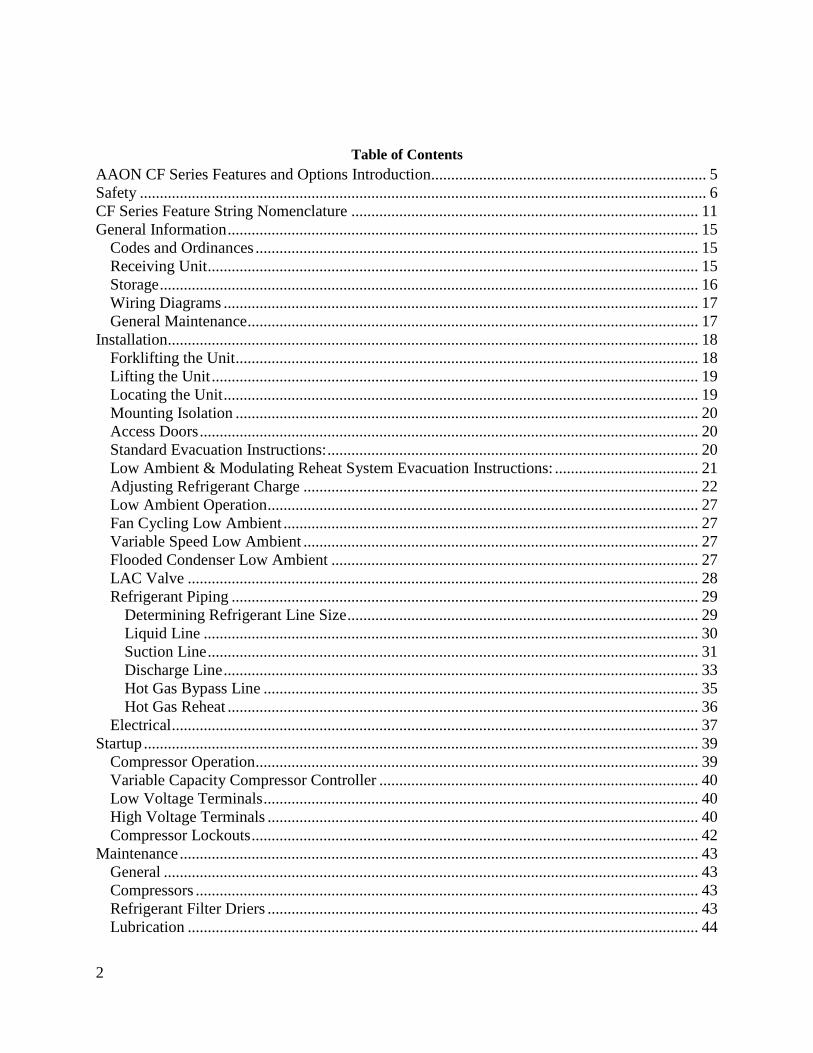
2
Table of Contents
AAON CF Series Features and Options Introduction 5 Safety 6 CF Series Feature String Nomenclature 11 General Information 15
Codes and Ordinances 15 Receiving Unit 15 Storage 16 Wiring Diagrams 17 General Maintenance 17
Installation 18 Forklifting the Unit 18
Lifting the Unit 19 Locating the Unit 19
Mounting Isolation 20 Access Doors 20
Standard Evacuation Instructions 20 Low Ambient amp Modulating Reheat System Evacuation Instructions 21 Adjusting Refrigerant Charge 22
Low Ambient Operation 27 Fan Cycling Low Ambient 27
Variable Speed Low Ambient 27 Flooded Condenser Low Ambient 27
LAC Valve 28 Refrigerant Piping 29
Determining Refrigerant Line Size 29 Liquid Line 30 Suction Line 31
Discharge Line 33 Hot Gas Bypass Line 35
Hot Gas Reheat 36 Electrical 37
Startup 39 Compressor Operation 39 Variable Capacity Compressor Controller 40
Low Voltage Terminals 40 High Voltage Terminals 40
Compressor Lockouts 42 Maintenance 43
General 43 Compressors 43 Refrigerant Filter Driers 43 Lubrication 44
3
Condenser Tube Inspection 44 Maintenance Recommendations 44 E-Coated Coil Cleaning 45 Service 48
Replacement Parts 48 AAON Technical Support 48
Split System Refrigerant Piping Diagrams 49
Index of Tables and Figures
Tables
Table 1 ndashClearances for Proper Operation 19 Table 2 ndash Clearances for Coil Pull 19
Table 3 - Acceptable Refrigeration Circuit Values 24
Table 4 ndash Charge to Flood Condenser Coil for Ambient Above 70degF 26 Table 5 ndash Charge to Flood Condenser Coil for Ambient Below 70degF 26 Table 6 - Nameplate Voltage Markings 37
Table 7 - Demand Signal vs Compressor Capacity Modulation 41 Table 8 - Thermistor Temperature vs Resistance Values 42
Table 9 - Max Filter Drier Pressure Drops 43 Table 10 - R-410A Refrigerant Temperature-Pressure Chart 44
Figures
Figure 1 - Forklifting a CF Series A Cabinet 18
Figure 2 - Forklifting a CF Series B and C Cabinet 18 Figure 3 ndash Lifting Details and Orientation of a CF Series 9-70 ton Condensing Unit 19 Figure 4 - Orientation of Series 2-7 ton Condensing Unit 19
Figure 5 ndash CU evacuation connections 21 Figure 6 ndash CU evacuation connections 22
Figure 7 - Adjustable Fan Cycling Switch 27 Figure 8 ndash LAC Piping Example 28 Figure 9 - Double Suction Riser Construction 32 Figure 10 ndash Heat Pump Piping Schematic of Cooling Mode in Double Riser 34 Figure 11 ndash Heat Pump Piping Schematic of Heating Mode in Double Riser 34
Figure 12 ndash Oil Return Line 36 Figure 13 - Variable Capacity Compressor Controller 40
Figure 14 - Compressor Controller Flash Code Details 41 Figure 15 - Adjustable compressor lockout 42 Figure 16 - Ambient sensor cover 42 Figure 17 - AC Split System Piping Suction Down 49 Figure 18 - AC Split System Piping Suction Up 50
Figure 19 - AC with LAC Split System Piping Suction Down 51 Figure 20 - AC with LAC Split System Piping Suction Up 52 Figure 21 - AC with Modulating Hot Gas Reheat Split System Piping Suction Down 53
4
Figure 22 - AC with Modulating Hot Gas Reheat Split System Piping Suction Up 54 Figure 23 - AC with Modulating Hot Gas Reheat Split + LAC System Piping Suction Down 55 Figure 24 - AC with Modulating Hot Gas Reheat Split + LAC System Piping Suction Up 56 Figure 25 - AC with Hot Gas Bypass Split System Piping Suction Down 57
Figure 26 - AC with Hot Gas Bypass Split System Piping Suction Up 58 Figure 27 - AC with Hot Gas Bypass + LAC Split System Piping Suction Down 59 Figure 28 - AC with Hot Gas Bypass + LAC Split System Piping Suction Up 60 Figure 29 - AC with Modulating Hot Gas Reheat and Hot Gas Bypass Split System Piping
Suction Down 61
Figure 30 - AC with Modulating Hot Gas Reheat and Hot Gas Bypass Split System Piping
Suction Up 62 Figure 31 - AC with Modulating Hot Gas Reheat and Hot Gas Bypass + LAC Split System
Piping Suction Down 63
Figure 32 - AC with Modulating Hot Gas Reheat and Hot Gas Bypass + LAC Split System
Piping Suction Up 64
Figure 33 - Heat Pump Split System Piping Suction Down 65 Figure 34 - Heat Pump Split System Piping Suction Up 66
Figure 35 - Heat Pump with Modulating Hot Gas Reheat Split System Piping Suction Down 67 Figure 36 - Heat Pump with Modulating Hot Gas Reheat Split System Piping Suction Up 68 Figure 37 - Heat Pump with Hot Gas Bypass Split System Piping Suction Down 69
Figure 38 - Heat Pump with Hot Gas Bypass Split System Piping Suction Up 70 Figure 39 ndash Heat Pump with Modulating Hot Gas Reheat and Hot Gas Bypass Split System
Piping Suction Down 71 Figure 40 ndash Heat Pump with Modulating Hot Gas Reheat and Hot Gas Bypass Split System
Piping Suction Up 72
V45040 Rev A 190709
(ACP J00424)
5
AAON CF Series Features and Options Introduction
Energy Efficiency
bull Two-Stage 10-100 Variable Capacity
or Tandem R-410A Scroll Compressors
bull Air-Source Heat Pump
bull VFD Controlled ECM Driven and
ECM Low Sound Condenser Fans
Humidity Control bull Modulating Hot Gas Reheat
bull Makeup Air Applications up to 100
Outside Air
Safety bull Phase and Brownout Protection
bull Single Point Non-Fused Disconnect
Power Switch
bull Automatic Low Pressure and Manual
Reset High Pressure Safety Cut-outs
bull Adjustable Compressor Lockout
Installation and Maintenance bull Isolated Controls and Compressor
Compartment
bull Access Doors with Full Length Stainless
Steel Piano Hinges
bull Molded Lockable Handles
bull Color-Coded Wiring Diagrams
bull Run Test Report and Installation Manual
Included in Controls Compartment
bull Factory Installed Convenience Outlet
bull Service Access Lights
bull Remote StartStop Terminals
bull Liquid Line Sight Glass
bull Compressor Isolation Valves
System Integration bull Complete Split System with AAON DX
Air Handling Units
bull Remote Air-Cooled Condenser Option
bull Labeled Split System Piping Stub Outs
with Shut-Off Valves
bull Flooded Condenser 0degF Low Ambient
Controls
bull Terminal Block for Thermostat with
Isolation Relays
bull Constant Air Volume (CAV) Makeup
Air (MUA) Variable Air Volume
(VAV) and Single Zone Variable Air
Volume (SZ VAV)
Environmentally Friendly bull R-410A Refrigerant
Extended Life bull Optional 5 Year Compressor Warranty
bull G90 Galvanized Steel Construction
bull 2500 Hour Salt Spray Tested Exterior
Corrosion Protection
bull 10000 Hour Salt Spray Tested Polymer
E-Coated Condenser Coils
bull Copper Fin and Stainless Steel Casing
Coils
bull Condenser Coil Guards
bull Custom Color Paint Options
6
Safety
Attention should be paid to the following statements
NOTE - Notes are intended to clarify the unit installation operation and maintenance
CAUTION - Caution statements are given to prevent actions that may result in equipment
damage property damage or personal injury
WARNING - Warning statements are given to prevent actions that could result in
equipment damage property damage personal injury or death
DANGER - Danger statements are given to prevent actions that will result in equipment
damage property damage severe personal injury or death
QUALIFIED INSTALLER Improper installation adjustment alteration service or maintenance can cause property damage personal injury or loss of life Startup and service must be performed by a Factory Trained Service Technician A copy of this IOM should be kept with the unit
WARNING
ELECTRIC SHOCK Electric shock hazard Before servicing shut off all electrical power to the unit including remote disconnects to avoid shock hazard or injury from rotating parts Follow proper Lockout-Tagout procedures
WARNING
ELECTRIC SHOCK FIRE OR EXPLOSION HAZARD Failure to follow safety warnings exactly could result in dangerous operation serious injury death or property damage Improper servicing could result in dangerous operation serious injury death or property damage When servicing controls label all
wires prior to disconnecting Reconnect wires correctly
Verify proper operation after servicing Secure all doors with key-lock or nut and bolt
WARNING
7
ROTATING COMPONENTS Unit contains fans with moving parts that can cause serious injury Do not remove grill containing fans until the power to the unit has been disconnected and fan has stopped rotating
WARNING
LIVE ELECTRICAL During installation testing servicing and troubleshooting of the equipment it may be necessary to work with live electrical components Only a qualified licensed electrician or individual properly trained in handling live electrical components shall perform these tasks Standard NFPA-70E an OSHA regulation requiring an Arc Flash Boundary to be field established and marked for identification of where appropriate Personal Protective Equipment (PPE) be worn should be followed
WARNING
FIRE EXPLOSION OR CARBON MONOXIDE POISONING HAZARD Failure to replace proper controls could result in fire explosion or carbon monoxide poisoning Failure to follow safety warnings exactly could result in serious injury death or property damage Do not store or use gasoline or other flammable vapors and liquids in the vicinity of this appliance
WARNING
GROUNDING REQUIRED All field installed wiring must be completed by qualified personnel Field installed wiring must comply with NECCEC local and state electrical code requirements Failure to follow code requirements could result in serious injury or death Provide proper unit ground in accordance with these code requirements
WARNING
VARIABLE FREQUENCY DRIVES
Do not leave VFDs unattended in hand mode or manual bypass Damage to personnel or equipment can occur if left unattended When in hand mode or manual bypass mode VFDs will not respond to controls or alarms
WARNING
8
LEAK TESTING
Do not use oxygen acetylene or air in place of refrigerant and dry nitrogen for leak testing A violent explosion may result causing injury or death
WARNING
VARIABLE FREQUENCY DRIVES
Electric motor over-current protection and overload protection may be a function of the Variable Frequency Drive to which the motors are wired Never defeat the VFD motor overload feature The overload ampere setting must not exceed 115 of the electric motors FLA rating as shown on the motor nameplate
CAUTION
PVC PIPING
PVC (Polyvinyl Chloride) and CPVC (Chlorinated Polyvinyl Chloride) are vulnerable to attack by certain chemicals Polyolester (POE) oils used with R-410A and other refrigerants even in trace amounts in a PVC or CPVC piping system will result in stress cracking of the piping and fittings and complete piping system failure
CAUTION
3-PHASE ROTATION
Rotation must be checked on all MOTORS AND COMPRESSORS of 3 phase units at startup by a qualified service technician Scroll compressors are directional and can be damaged if rotated in the wrong direction Compressor rotation must be checked using suction and discharge gauges Fan motor rotation should be checked for proper operation Alterations should only be made at the unit power connection
CAUTION
UNIT HANDLING To prevent injury or death lifting equipment capacity shall exceed unit weight by an adequate safety factor Always test-lift unit not more than 24 inches high to verify proper center of gravity lift point to avoid unit damage injury or death
WARNING
DOOR LATCHES
Door compartments containing hazardous voltage or rotating parts are equipped with door latches that allow locks Door latches are shipped with a nut and bolt requiring tooled access If the shipping hardware is not replaced with a pad lock always re-install the nut and bolt after closing the door to maintain tooled access
CAUTION
9
ENCLOSED AREA
Do not work in an enclosed area where refrigerant or nitrogen gases may be leaking A sufficient quantity of vapors may be present and cause
injury or death
WARNING
COMPRESSOR LUBRICANT
Polyolester (POE) and Polyvinylether (PVE) oils are two types of lubricants used in hydrofluorocarbon (HFC) refrigeration systems Refer to the compressor label for the proper compressor lubricant type
CAUTION
COIL CLEANERS
To prevent damage to the unit do not use acidic chemical coil cleaners Do not use alkaline chemical coil cleaners with a pH value greater than 85 after mixing without first using an aluminum corrosion inhibitor in the cleaning solution
CAUTION
COIL CLEANERS
Some chemical coil cleaning compounds are caustic or toxic Use these substances only in accordance with the manufacturerrsquos usage instructions Failure to follow instructions may result in equipment damage injury or death
WARNING
COIL CLEANING
Do not clean DX refrigerant coils with hot water or steam The use of hot water or steam on refrigerant coils will cause high pressure inside the coil tubing and damage to the coil
CAUTION
CONVENIENCE OUTLETS
Factory installed convenience outlets are not intended for use while the unit is operating
WARNING
10
1 Startup and service must be performed by
a Factory Trained Service Technician
2 The unit is for outdoor use only See
General Information section for more
information
3 Every unit has a unique equipment
nameplate with electrical operational
and unit clearance specifications
Always refer to the unit nameplate for
specific ratings unique to the model
purchased
4 READ THE ENTIRE INSTALLATION
OPERATION AND MAINTENANCE
MANUAL OTHER IMPORTANT
SAFETY PRECAUTIONS ARE
PROVIDED THROUGHOUT THIS
MANUAL
5 Keep this manual and all literature
safeguarded near or on the unit
COMPRESSOR CYCLING
5 MINUTE MINIMUM OFF TIME To prevent motor overheating compressors must cycle off for a minimum of 5 minutes
5 MINUTE MINIMUM ON TIME To maintain the proper oil level compressors must cycle on for a minimum of 5 minutes The cycle rate must not exceed 6 starts per hour
WARNING
CF Series Feature String Nomenclature
Model Options Unit Feature Options G
EN
MJ
RE
V
SIZ
E
SE
RIE
S
MN
RE
V
VL
T
A1
A2
A3
A4
A5
1
2A
2B
3A
3B
4
5
6A
6B
6C
7
8A
8B
8C
8D
9
10
11
12
13
14
15
CF A - 015 - B - A - 3 - D C 0 0 K 0 - A 0 - E 0 - C 0 - A N 0 - B - D E 0 0 - 0 0 A 0 E 0 0
0 0 0 0 0 D B
16
17
18
19
20
21
22
11
CF Series Feature String Nomenclature
MODEL OPTIONS Series and Generation
CF
Major Revision
A
Unit Size
002 = 2 ton Capacity
003 = 3 ton Capacity
004 = 4 ton Capacity
005 = 5 ton Capacity
006 = 6 ton Capacity
007 = 7 ton Capacity
009 = 9 ton Capacity
011 = 11 ton Capacity
013 = 13 ton Capacity
015 = 15 ton Capacity
016 = 16 ton Capacity
018 = 18 ton Capacity
020 = 20 ton Capacity
025 = 25 ton Capacity
026 = 26 ton Capacity
030 = 30 ton Capacity
031 = 31 ton Capacity
040 = 40 ton Capacity
050 = 50 ton Capacity
060 = 60 ton Capacity
070 = 70 ton Capacity
Series
A = 2-7 ton units
B = 9-15 ton units
C = 16-25 amp 30 ton units
D = 26 amp 31-70 ton units
Minor Revision
A
Voltage
1 = 230V1Φ60Hz
2 = 230V3Φ60Hz
3 = 460V3Φ60Hz
4 = 575V3Φ60Hz
8 = 208V3Φ60Hz
9 = 208V1Φ60Hz
A1 Compressor Style
0 = Air-Cooled Condenser - No Compressors
(1 Circuit)
A = R-410A Scroll Compressors
B = R-410A Two Step Capacity Scroll Compressors
D = R-410A Variable Capacity Scroll Compressors
E = R-410A Tandem Scroll Compressors
G = R-410A Tandem Variable Capacity Scroll
Compressors
P = Air-Cooled Condenser - No Compressors
(2 Circuits)
Q = Air-Cooled Condenser - No Compressors
(4 Circuits)
A2 Condenser Style
C = Air-Cooled Condenser
J = Air-Source Heat Pump
A3 Configuration
0 = Standard
A4 Coating
0 = Standard
E = Polymer E-Coated Condenser Coil
G = Copper Fin + Stainless Steel Casing - Condenser
Coil
A5 Staging
0 = No Cooling
G = 1 OnOff Refrigeration System
H = 1 Variable Capacity Refrigeration System
J = 2 OnOff Refrigeration Systems
K = 1 Variable Capacity Refrigeration System + 1
OnOff Refrigeration System
L = 2 Variable Capacity Refrigeration System
R = 4 OnOff Refrigeration Systems
T = 2 Variable Capacity Refrigeration Systems + 2
OnOff Refrigeration Systems
U = 4 Variable Capacity Refrigeration Systems
CF Series Feature String Nomenclature
Model Options Unit Feature Options G
EN
MJR
EV
SIZ
E
SE
RIE
S
MN
RE
V
VL
T
A1
A2
A3
A4
A5
1
2A
2B
3A
3B
4
5
6A
6B
6C
7
8A
8B
8C
8D
9
10
11
12
13
14
15
CF A - 015 - B - A - 3 - D C 0 0 K 0 - A 0 - E 0 - C 0 - A N 0 - B - D E 0 0 - 0 0 A 0 E 0 0
0 0 0 0 0 D B
16
17
18
19
20
21
22
12
UNIT FEATURE OPTIONS 1 Unit Orientation
0 = Vertical Condenser Discharge - Standard Access
A = Horizontal Condenser Discharge - Standard
Access
2A Refrigeration Control
0 = Standard
A = 5 Minute Compressor Off Timer + 20 Second
Compressor Stage Delay
C = Adjustable Fan Cycling
D = Adjustable Compressor Lockout
G = Option A + Adjustable Fan Cycling
H = Option A + Adjustable Compressor Lockout
M = Adjustable Fan Cycling + Adjustable
Compressor Lockout
W = Option A + Adjustable Fan Cycling +
Adjustable Compressor Lockout
2B Blank
0 = Standard
3A Refrigeration Options
0 = Standard
A = Hot Gas Bypass Lead Stage [HGB]
B = HGB Lead + HGB Lag
D = Hot Gas Bypass Non-Variable Capacity
Refrigeration Systems [HGBNV]
E = Modulating Hot Gas Reheat [MHGR]
H = HGB + MHGR
J = HGB Lead + HGB Lag + MHGR
L = HGBNV + MHGR
3B Blank
0 = Standard
4 Refrigeration Accessories
0 = Standard
A = Sight Glass
B = Compressor Isolation Valves
C = Options A + B
D = Flooded Condenser 0degF Low Ambient Controls ndash
One Circuit
E = Options A + D
F = Options B + D
G = Options A + B + D
H = Flooded Condenser 0degF Low Ambient Controls-
Two Circuits
J = Options A + H
K = Options B + H
L = Options A + B + H
R = Flooded Condenser 0degF Low Ambient Controls ndash
Four Circuits
S = Options A + R
T = Options B + R
U = Options A + B + R
5 Blank
0 = Standard
6A Unit Disconnect Type
0 = Single Point Power Block
A = Single Point Power Non-Fused Disconnect
6B Disconnect 1 Size
0 = Standard
N = 100 amps
R = 150 amps
V = 250 amps
Z = 400 amps
6C Blank
0 = Standard
CF Series Feature String Nomenclature
Model Options Unit Feature Options
GE
N
MJR
EV
SIZ
E
SE
RIE
S
MN
RE
V
VL
T
A1
A2
A3
A4
A5
1
2A
2B
3A
3B
4
5
6A
6B
6C
7
8A
8B
8
C
8D
9
10
11
12
13
14
15
CF A - 015 - B - 0 - 3 - D C 0 0 K 0 - A 0 - E 0 - C 0 - A N 0 - B - D C 0 0 - 0 0 A 0 E 0 0 0 0 0 0 0 D B
16
17
18
19
20
21
22
13
7 Accessories
0 = Standard
B = Phase amp Brown Out Protection
D = Suction Pressure Transducer on Each
Refrigeration Circuit
E = Compressor Sound Blanket
L = Options B + D
M = Options B + E
Q = Options D + E
1 = Options B + D + E
8A Control Sequence
A = Terminal Block for Thermostat w Isolation
Relays
D = VAV Unit Controller - VAV Cool + CAV Heat
E = CAV Unit Controller
F = Makeup Air Unit Controller - CAV Cool + CAV
Heat
H = Constant Volume HP Unit Controller - CAV
Cool + CAV Heat
J = Makeup Air HP Unit Controller - CAV Cool +
CAV Heat
N = Field Installed DDC Controls by Others with
Isolation Relays
8B Control Suppliers
0 = Standard
E = Orion VCC-X (Main Controller in Air Handling
Unit)
H = AAON Touchscreen Controller (Main Controller
in Air Handling Unit)
8C Control Supplier Options
0 = Standard
8D BMS Connection amp Diagnostics
0 = Standard
9 Blank
0 = Standard
10 Blank
0 = Standard
11 Maintenance Accessories
0 = Standard
A = Factory Wired 115VAC Convenience Outlet
B = Field Wired 115VAC Convenience Outlet
C = Service Lights
E = Remote Unit StartStop Terminals
F = Options A + C
H = Options A + E
J = Options B + C
L = Options B + E
N = Options C + E
R = Options A + C + E
U = Options B + C + E
12 Code Options
0 = Standard ETL USA Listing
B = ETL USA + Canada Listing
13 Air-Cooled Condenser Accessories
0 = Standard
A = Condenser Coil Guard
C = ECM Condenser Fan Head Pressure Control
E = VFD Condenser Fan Head Pressure Control
G = Options A + C
J = Options A + E
N = ECM Condenser Fan Head Pressure Control +
Low Sound Condenser Fan
S = Options A + N
14 Blank
0 = Standard
15 Blank
0 = Standard
16 Electrical Options
0 = Standard
17 Shipping Options
0 = Standard
A = Crating
B = Export Crating
CF Series Feature String Nomenclature
Model Options Unit Feature Options G
EN
MJR
EV
SIZ
E
SE
RIE
S
MN
RE
V
VL
T
A1
A2
A3
A4
A5
1
2A
2B
3A
3B
4
5
6A
6B
6C
7
8A
8B
8C
8D
9
10
11
12
13
14
15
CF A - 015 - B - A - 3 - D C 0 0 K 0 - A 0 - E 0 - C 0 - A N 0 - B - D E 0 0 - 0 0 A 0 E 0 0
0 0 0 0 0 D B 1
6
17
18
19
20
21
22
14
18 Blank
0 = Standard
19 Blank
0 = Standard
20 Cabinet Material
0 = Galvanized Steel Cabinet
21 Warranty
0 = Standard
D = Compressor Warranty - Years 2-5
22 Type
B = Premium AAON Gray Paint Exterior
E = Premium AAON Gray Paint Ext + Shrink Wrap
X = SPA + Premium AAON Gray Paint Exterior
1 = SPA + Premium AAON Gray Paint Exterior +
Shrink Wrap
15
General Information
AAON CF Series air-cooled condensers and
condensing units have been designed for
outdoor use only They are factory
assembled wired charged and run-tested
Codes and Ordinances
CF Series units have been tested and
certified by ETL in accordance with UL
Safety Standard 1995CSA C222 No 236
System should be sized in accordance with
the American Society of Heating
Refrigeration and Air Conditioning
Engineers Handbook
Installation of CF Series units must conform
to the ICC standards of the International
Mechanical Code the International Building
Code and local building plumbing and
electrical codes All appliances must be
electrically grounded in accordance with
local codes or in the absence of local codes
the current National Electric Code
ANSINFPA 70 or the current Canadian
Electrical Code CSA C221
Receiving Unit
When received the unit should be checked
for damage that might have occurred in
transit If damage is found it should be noted
on the carrierrsquos freight bill A request for
inspection by carrierrsquos agent should be made
in writing at once Nameplate should be
checked to ensure the correct model sizes and
voltages have been received to match the job
requirements
If repairs must be made to damaged goods
then the factory should be notified before any
repair action is taken in order to protect the
warranty Certain equipment alteration
repair and manipulation of equipment
without the manufacturerrsquos consent may void
the product warranty Contact AAON
Technical Support for assistance with
handling damaged goods repairs and freight
claims (918) 382-6450
SHARP EDGES
Coils and sheet metal surfaces present sharp edges and care must be taken when working with equipment
WARNING
QUALIFIED INSTALLER
Improper installation adjustment alteration service or maintenance can cause property damage personal injury or loss of life Installation and service must be performed by a Factory Trained Service Technician
WARNING
Failure to observe the following instructions will result in premature failure of your system and possible voiding of the warranty
WARNING
16
Storage
If installation will not occur immediately
following delivery store equipment in a dry
protected area away from construction traffic
and in the proper orientation as marked on the
packaging with all internal packaging in
place Secure all loose-shipped items
Failure to observe the following instructions
will result in premature failure of your
system and possible voiding of the warranty
Never turn off the main power supply to the
unit except for complete shutdown When
power is cut off from the unit any
compressors using crankcase heaters cannot
prevent refrigerant migration This means the
compressor will cool down and liquid
refrigerant may accumulate in the
compressor The compressor is designed to
pump refrigerant gas and damage may occur
if liquid enters the compressor when power is
restored
Before unit operation the main power switch
must be turned on for at least twenty-four
hours for units with compressor crankcase
heaters This will give the crankcase heater
time to clear any liquid accumulation out of
the compressor before it is required to run
Always control the system from the control
panel never at the main power supply (except
for emergency or for complete shutdown of
the system)
CLEAN AIR ACT
The Clean Air Act of 1990 bans the intentional venting of refrigerant as of July 1 1992 Approved methods of recovery recycling or reclaiming must be followed
CAUTION
CRANKCASE HEATER OPERATION
Units are equipped with compressor crankcase heaters which should be energized at least 24 hours prior to cooling operation to clear any liquid refrigerant from the compressors
CAUTION
3-PHASE ROTATION
Rotation must be checked on all MOTORS AND COMPRESSORS of three phase units All motors to include and not be limited to pump motors and condenser fan motors should all be checked by a qualified service technician at startup and any wiring alteration should only be made at the unit power connection
CAUTION
17
The standard compressors must be on a
minimum of 5 minutes and off for a minimum
of 5 minutes The cycle rate must be no more
than 6 starts per hour
The variable capacity compressors must be
on a minimum of 3 minutes and off for a
minimum of 3 minutes The cycle rate must
be no more than 6 starts per hour
The compressor life will be seriously
shortened by reduced lubrication and the
pumping of excessive amounts of liquid oil
and liquid refrigerant
Wiring Diagrams
A complete set of unit specific wiring
diagram in point-to-point form is laminated
in plastic and located inside the control
compartment door
General Maintenance
When the initial startup is made and on a
periodic schedule during operation it is
necessary to perform routine service checks
on the performance of the condensing unit
This includes reading and recording suction
pressures and checking for normal sub-
cooling and superheat
COMPRESSOR ROTATION
Scroll compressors are directional and will be damaged by operation in the wrong direction Low pressure switches on compressors have been disconnected after factory testing Rotation should be checked by a qualified service technician at startup using suction and discharge pressure gauges and any wiring alteration should only be made at the unit power connection
COMPRESSOR CYCLING
5 MINUTE MINIMUM OFF TIME To prevent motor overheating compressors must cycle off for a minimum of 5 minutes
5 MINUTE MINIMUM ON TIME To maintain the proper oil level compressors must cycle on for a minimum of 5 minutes The cycle rate must not exceed 6 starts per hour
WARNING
CAUTION
18
Installation
Forklifting the Unit
CF Series condensing unit sizes 2-25 amp 30
tons can be lifted using a forklift 2-7 ton
units must have forks at least 48rdquo in length
9-25 amp 30 ton units must have forks 72rdquo in
length or the forks must have 72rdquo fork
extensions Standard units can be lifted from
all sides except the condenser coil side CF
Series condensing unit sizes 26 amp 31-70 tons
cannot be lifted using a forklift They can be
lifted as shown in Figure 3
Forks must be perpendicular to the unit and
they must be in far enough that the back of
the forks are no more than 6rdquo away from the
edge of the unit
Figure 1 - Forklifting a CF Series A Cabinet
Figure 2 - Forklifting a CF Series B and C
Cabinet
FORKLIFTING 2-7 TON UNITS
Forks or Fork Extensions must be at least 48rdquo in length
CAUTION
FORKLIFTING 9-25 amp 30 TON UNITS
Forks or Fork Extensions must be at least 72rdquo in length
CAUTION
19
Lifting the Unit
If cables or chains are used to hoist the unit
they must be the same length Minimum
cable length is 99rdquo for CF Series 9-70 ton
units CF Series 2-7 ton units do not include
factory installed lifting lugs and should be
lifted by forklift only Care should be taken
to prevent damage to the cabinet coils and
condenser fans
Before lifting unit be sure that all shipping
material has been removed from unit Secure
hooks and cables at all lifting points lugs
provided on the unit
Figure 3 ndash Lifting Details and Orientation of
a CF Series 9-70 ton Condensing Unit
Locating the Unit
The CF Series condenser and condensing unit
is designed for outdoor applications and
mounting at ground level or on a rooftop It
must be placed on a level and solid
foundation that has been prepared to support
its weight When installed at ground level a
one-piece concrete slab should be used with
footings that extend below the frost line Also
with ground level installation care must be
taken to protect the coil fins from damage due
to vandalism or other causes
The first clearance table below gives the
clearance values for proper unit operation
The second clearance table gives the
clearance necessary for removing the coil
without disassembling a large part of the
condensing unit For ease of removing the
condenser coil use the second table
clearances for the right hand side of the unit
Table 1 ndashClearances for Proper Operation
Location Unit Size
2-7 tons 9-70 tons
Front -
(Controls
Side)
Unobstructed 36rdquo
Left Side 6rdquo 30rdquo
Right Side 6rdquo 36rdquo
Top 3rdquo Unobstructed
Back 18rdquo 6rdquo
Table 2 ndash Clearances for Coil Pull
Unit Size Right Hand Side
2-7 tons 42rdquo
9-15 tons 42rdquo
16-25 amp 30 tons 54rdquo
26 amp 31-70 tons 66rdquo
Figure 4 - Orientation of Series 2-7 ton
Condensing Unit
20
The placement relative to the building air
intakes and other structures must be carefully
selected Airflow to and from the condenser
or condensing unit must not be restricted to
prevent a decrease in performance and
efficiency
The installation position for 9-70 ton units
must provide at least 30rdquo of left and right side
clearance for proper airflow to the condenser
coils When units are mounted adjacent to
each other the minimum right and left side
clearance required between the units is 60rdquo or
5 feet Similarly when 2-7 ton units are
mounted adjacent to each other the minimum
clearance required between the back side of
the units is 36rdquo or 3 feet
Units should not be installed in an enclosure
or pit that is deeper than the height of the unit
When recessed installation is necessary the
clearance to maintain proper airflow is at
least 5 feet (3 feet for 2-7tons)
CF Series condensers and condensing units
that have a vertical air discharge must have
no obstruction above the equipment Do not
place the unit under an overhang CF Series
condensers and condensing units that have a
horizontal discharge must have no
obstruction in front of the unit
For proper unit operation the immediate area
around condenser must remain free of debris
that may be drawn in and obstruct airflow in
the condensing section
Consideration must be given to obstruction
caused by snow accumulation when placing
the unit
Mounting Isolation
For roof mounted applications or anytime
vibration transmission is a factor vibration
isolators may be used
Access Doors
Access doors are provided to the compressor
and electrical compartment
Standard Evacuation Instructions
Proper system evacuation is critical to
remove moisture and non-condensables from
the system before charging the system with
refrigerant A newly installed AAON
condensing unit has already been evacuated
and charged with some refrigerant at the
factory When evacuating a new system
keep the condensing unit service valves
closed and evacuate the suction and liquid
lines and the air handling unit If the entire
system must be evacuated use the following
procedure to ensure the entire system is
pulled into a good vacuum
1 System evacuation should be
performed anytime a system is open to
atmospheric pressure The POE oils
used with R-410A are extremely
hydroscopic in nature and immediately
begin pulling in moisture once the
system is opened to the atmosphere
2 Before starting to evacuate the
system you MUST ensure that there are
no leaks by pressurizing the system with
PVC PIPING
PVC (Polyvinyl Chloride) and CPVC (Chlorinated Polyvinyl Chloride) are vulnerable to attack by certain chemicals Polyolester (POE) oils used with R-410A and other refrigerants even in trace amounts in a PVC or CPVC piping system will result in stress cracking of the piping and fittings and complete piping system failure
CAUTION
21
400 psig of dry nitrogen and verifying no
pressure loss after one hour
3 Four valve manifold gauge sets are
more effective than standard manifold
gauge sets due to the extra hose port in
combination with a 38rsquorsquo evacuation
port The larger diameter evacuation port
will expedite system evacuation
4 The manifold set should be connected
to the condensing unit with one hose on
the suction line service valve one hose
on the liquid line service valve and if an
extra Schrader valve is field installed on
the suction line connect a third hose (not
shown) The vacuum pump should be
connected to the manifold set using a
38rdquo vacuum rated hose Figure 5 shows
two circuits Both circuits must be
evacuated separately
Figure 5 ndash CU evacuation connections
5 An accurate micron gauge must be
used and checked by pulling a vacuum
on the gauge by itself and verify a rapid
drop to less than 100 microns within a
few minutes
6 The micron gauge should not be
attached to the system until the gauge
manifold is reading 28rsquorsquo of vacuum to
ensure the micron gauge does not see
pressure and is thus damaged MICRON
GAUGES WILL BE DAMAGED BY
PRESSURE
7 It is a good practice to replace the
vacuum pump oil after one hour of the
evacuation process The oil can be
broken down in the pump in the initial
first hour causing system evacuation to
take longer than it should
8 The minimum micron level required
by AAON is 350 microns for systems
using POE oils
9 The system should then be isolated
and the pump turned off to check for
vacuum rise due to leaks or moisture in
the system The micron gauge should
not rise above 500 microns after 30
minutes of wait time
Low Ambient amp Modulating Reheat
System Evacuation Instructions
Proper system evacuation is critical to
remove moisture and non-condensables from
the system before charging the system with
refrigerant Systems with low ambient
flooded condenser option require the
following procedure to ensure the entire
system is pulled into a good vacuum
1 System evacuation should be
performed anytime a system is open to
atmospheric pressure The POE oils
used with R-410A are extremely
hydroscopic in nature and immediately
begin pulling in moisture once the
system is opened to the atmosphere
2 Open the reheat valve to 50 when
evacuating
3 Before starting to evacuate the
system you MUST ensure that there are
no leaks by pressurizing the system with
22
400 psig of dry nitrogen and verifying no
pressure loss after one hour
4 Four valve manifold gauge sets are
more effective than standard manifold
gauge sets due to the extra hose port in
combination with a 38rsquorsquo evacuation
port The larger diameter evacuation port
will expedite system evacuation
5 The manifold set should be connected
to the condensing unit with one hose on
the suction line service valve one hose
on the liquid line service valve and a
third hose on the reheat line service
valve The vacuum pump should be
connected to the manifold set using a
38rdquo vacuum rated hose Figure 6 shows
two circuits The first circuit has a
reheat line the second circuit is just the
suction and liquid line Both circuits
must be evacuated separately
Figure 6 ndash CU evacuation connections
6 FAILURE to connect to the liquid
line service valve will result in the
receiver tank not being fully evacuated
and most likely lead to non-
condensables in the system
7 An accurate micron gauge must be
used and checked by pulling a vacuum
on the gauge by itself and verify a rapid
drop to less than 100 microns within a
few minutes
8 The micron gauge should not be
attached to the system until the gauge
manifold is reading 28rsquorsquo of vacuum to
ensure the micron gauge does not see
pressure and is thus damaged MICRON
GAUGES WILL BE DAMAGED BY
PRESSURE
9 It is a good practice to replace the
vacuum pump oil after one hour of the
evacuation process The oil can be
broken down in the pump in the initial
first hour causing system evacuation to
take longer than it should
10 The minimum micron level required
by AAON is 350 microns for systems
using POE oils
11 The system should then be isolated
and the pump turned off to check for
vacuum rise due to leaks or moisture in
the system The micron gauge should
not rise above 500 microns after 30
minutes of wait time
Adjusting Refrigerant Charge
All AAON CF Series condensers and
condensing units are shipped with a factory
holding charge The factory charge is
different depending on the unit size and
system (heat pump modulating hot gas
reheat LAC) The factory charge per circuit
is shown on the unit nameplate Adjusting the
charge of the system will be required during
installation
23
Adjusting the charge of a system in the field
must be based on determination of liquid sub-
cooling and evaporator superheat On a
system with a thermostatic expansion valve
liquid sub-cooling is more representative of
the charge than evaporator superheat but both
measurements must be taken
Before Charging
Refer to the Unit Nameplate to determine
which refrigerant must be used to charge the
system
Unit being charged must be at or near full
load conditions before adjusting the charge
Units equipped with hot gas bypass must
have the hot gas bypass valve closed to get
the proper charge
Units equipped with hot gas reheat must be
charged with the hot gas valve closed while
the unit is in cooling mode After charging
unit should be operated in reheat
(dehumidification) mode to check for correct
operation
Units equipped with heat pump options
should be charged in cooling mode to get the
proper charge After charging unit should be
operated in heating mode to check for correct
charge Charge may need to be adjusted for
heating mode If adjustments are made in the
heating mode cooling mode must be rerun to
verify proper operation
After adding or removing charge the system
must be allowed to stabilize typically 10-15
minutes before making any other
adjustments
The type of unit and options determine the
ranges for liquid sub-cooling and evaporator
superheat Refer to Table 3 when determining
the proper sub-cooling
For units equipped with low ambient (0degF)
option see the special charging instructions at
the end of this section
Checking Liquid Sub-cooling
Measure the temperature of the liquid line as
it leaves the condenser coil
Read the gauge pressure at the liquid line
close to the point where the temperature was
taken You must use liquid line pressure as it
will vary from discharge pressure due to
condenser coil pressure drop
Convert the pressure obtained to a saturated
temperature using the appropriate refrigerant
temperature-pressure chart
COMPRESSOR LUBRICANT
Polyolester (POE) and Polyvinylether (PVE) oils are two types of lubricants used in hydrofluorocarbon (HFC) refrigeration systems Refer to the compressor label for the proper compressor lubricant type
CAUTION
CLEAN AIR ACT
The Clean Air Act of 1990 bans the intentional venting of refrigerant (CFCrsquos and HCFCrsquos) as of July 1 1992 Approved methods of recovery recycling or reclaiming must be followed Fines andor incarceration may be levied for non-compliance
CAUTION
24
Subtract the measured liquid line temperature
from the saturated temperature to determine
the liquid sub-cooling
Compare calculated sub-cooling to Table 3
for the appropriate unit type and options
Table 3 - Acceptable Refrigeration Circuit
Values
Cooling
Mode
Liquid Sub-
Cooling
Values
Cooling Only Unit4 8-15degF
Cooling Only Unit with Hot
Gas Reheat14 5-15degF
Heat PumpUnit24 2-4degF
Heat Pump Unit with Hot
Gas Reheat34 2-6degF
Cooling Only Unit with
LAC4 8-15degF
Cooling Only Unit with Hot
Gas Reheat amp LAC4 8-15degF
Notes 1 Must be charged with the hot gas valve
closed After charging unit should be
operated in reheat (dehumidification) mode
to check for correct operation
2 The sub-cooling value in this table is for the
unit running in cooling mode of operation
After charging unit should be operated in
heating mode to check for correct operation
3 The sub-cooling value in this table is for the
unit running in cooling mode of operation
and the hot gas valve closed After charging
unit should be operated in reheat
(dehumidification) mode to check for correct
operation and then in heating mode to check
for correct operation
4 Sub-cooling must be increased by 1degF per 10
feet of vertical liquid line rise for R-410A
(AHU above CU) For example a cooling
only unit with hot gas reheat and a vertical
liquid drop can charge to a sub-cooling value
of 5-15degF but a cooling only unit with hot
gas reheat and a vertical liquid rise of 30 ft
must charge to a sub-cooling value of at least
8-15degF DO NOT OVERCHARGE
Refrigerant overcharging leads to excess
refrigerant in the condenser coils resulting in
elevated compressor discharge pressure
Checking Evaporator Superheat
Measure the temperature of the suction line
close to the compressor
Read gauge pressure at the suction line close
to the compressor
Convert the pressure obtained to a saturated
temperature using the appropriate refrigerant
temperature-pressure chart
Subtract the saturated temperature from the
measured suction line temperature to
determine the evaporator superheat
For refrigeration systems with tandem
compressors it is critical that the suction
superheat setpoint on the TXV is set with one
compressor running The suction superheat
should be 10-13degF with one compressor
running The suction superheat will increase
with both compressors in a tandem running
Inadequate suction superheat can allow liquid
refrigerant to return to the compressors which
will wash the oil out of the compressor Lack
of oil lubrication will destroy a compressor
Liquid sub-cooling should be measured with
both compressors in a refrigeration system
running
Compare calculated superheat to the
acceptable cooling mode superheat values of
8-15degF for all system types Superheat will
increase with long suction line runs
25
Adjusting Sub-cooling and Superheat
Temperatures
The system is overcharged if the sub-cooling
temperature is too high compared to Table 3
and the evaporator is fully loaded (low loads
on the evaporator result in increased sub-
cooling) and the evaporator superheat is
within the temperature range of 8-15degF (high
superheat results in increased sub-cooling)
Correct an overcharged system by reducing
the amount of refrigerant in the system to
lower the sub-cooling
The system is undercharged if the superheat
is too high and the sub-cooling is too low
Correct an undercharged system by adding
refrigerant to the system to reduce superheat
and raise sub-cooling
If the sub-cooling is correct and the superheat
is too high the TXV may need adjustment to
correct the superheat
DO NOT OVERCHARGE Refrigerant overcharging leads to excess refrigerant in the condenser coils resulting in elevated compressor discharge pressure
CAUTION
EXPANSION VALVE ADJUSTMENT
Thermal expansion valves must be adjusted to approximately 8-15degF of suction superheat Failure to have sufficient superheat will damage the compressor and void the warranty
CAUTION
26
Special Low Ambient Option Charging
Instructions
For units equipped with low ambient
refrigerant flood back option being charged
in the summer when the ambient
temperature is warm
If the ambient is above 70degF charge to
approximately 1-2degF of sub-cooling
measured at the inlet to the expansion valve
Once enough charge has been added to get
the evaporator superheat and sub-cooling
values to the correct setting more charge
must be added Use Table 4 to find the
additional charge amount required for the
system when running in cold ambient
conditions
Table 4 ndash Charge to Flood Condenser Coil
for Ambient Above 70degF
CF Size of
circuits
Per Circuit
Charge (lbs)
CF 2 3 1 49
CF 4 5 6 7 1 92
CF 9 11 2 91
CF 13 15 2 121
CF 16 18 2 131
CF 20 25 30 2 175
CF 26 31 40 2 180
4 91
CF 50 60 70 2 438
4 221
For units equipped with low ambient
refrigerant flood back option being charged
in the winter when the ambient
temperature is cold
1 If the ambient is below 70degF charge
to approximately 1-2degF of sub-cooling
measured at the inlet to the expansion
valve Once enough charge has been
added to get the evaporator superheat
and sub-cooling values to the correct
setting more charge may need to be
added If the ambient temperature is 0degF
no more charge is required Ambient
temperatures above 0degF will require a
percentage of the per circuit charge
values from Table 4 Using your
ambient temperature find the
percentage value from Table 5 and
multiply the Per Circuit Charge value
from Table 4 and the value to
determine the additional charge amount
Table 5 ndash Charge to Flood Condenser
Coil for Ambient Below 70degF
Condenser
Ambient
Temperature ˚F
Percentage
Per Circuit
Charge from
Table 4
60 60
50 37
40 24
30 15
20 8
0 0
2 The unit should be checked for proper
operation once the ambient temperature
is above 80degF
Example A CF size 31 with tandem
compressors where the ambient
temperature is 40degF
From Table 4 ndash 18 lbs refrigerant charge
per circuit (tandem compressors would
have 2 circuits in this size of CF)
From Table 5 ndash 24 of Table 4 charge
Additional charge needed for a unit with
low ambient flooded condenser controls
= 18 lbs 024 = 432 lbs additional
refrigerant charge per circuit
27
Low Ambient Operation
During low ambient temperatures the vapor
refrigerant will migrate to the cold part of the
system and condense into liquid All CF
Series compressors are provided with factory
installed crankcase heaters to help prevent
liquid refrigerant from slugging the
compressors during startup in low ambient
conditions The condenser or condensing unit
must have continuous power 24 hours prior
to startup This ensures the compressor will
receive sufficient refrigerant vapor at startup
Standard units can operate down to 55degF
ambient temperature
AAON condenser fan head pressure control
units can operate down to 35degF ambient
temperature Three different condenser fan
head pressure control options available are
adjustable fan cycling ECM condenser fan
or VFD controlled condenser fans See
detailed information following
The AAON low ambient (condenser flood-
back) system is used to operate a refrigerant
system down to 0degF outside air temperature
See detailed information following
Fan Cycling Low Ambient
Adjustable fan cycling is a low ambient head
pressure control option that cycles the
condenser fans to maintain refrigerant circuit
head pressures at acceptable levels during
cooling operation The head pressure set
point (100-470 psi) and pressure differential
(35-200 psi) can be field adjusted using a
flathead screwdriver For example if the
head pressure is set to 300psi and the
differential is set to 100psi then fans will cut
in at 300psi and cut out at 200psi Fan
cycling and variable speed condenser fan
head pressure control options allow
mechanical cooling with ambient
temperatures down to 35degF
Figure 7 - Adjustable Fan Cycling Switch
Variable Speed Low Ambient
Variable speed condenser fan head pressure
control is a low ambient head pressure
control option that sends a variable signal in
relation to the refrigerant circuit head
pressure of the system to an electronically
commutated motor (ECM) or VFD The
motor either speeds up or slows down air
flow accordingly in order to maintain
constant head pressure Fan cycling and
variable speed condenser fan head pressure
control options allow mechanical cooling
with ambient temperatures down to 35degF
Flooded Condenser Low Ambient
Flooded condenser low ambient control
maintains normal head pressure during
periods of low ambient When the ambient
temperature drops the condensing
temperature and therefore pressure drops
Without ambient control the system would
shut down on low discharge pressure The
flooded condenser method of low ambient
control fills the condenser coil with liquid
refrigerant decreasing the heat transfer
capacity of the coil which allows the coil to
operate at an acceptable discharge pressure
28
The condenser coil will not be flooded during
summer ambient temperatures so a receiver
is included to store the additional liquid
refrigerant required to flood the condenser
coil in low ambient The receiver is factory-
sized to contain all of the flooded volume
Without a receiver there would be high head
pressures during higher ambient conditions
The low ambient system maintains normal
head pressure during periods of low ambient
by restricting liquid flow from the condenser
to the receiver and at the same time
bypassing hot gas around the condenser to the
inlet of the receiver This reduces liquid
refrigerant flow from the condenser reducing
its effective surface area which in turn
increases the condensing pressure At the
same time the bypassed hot gas raises liquid
pressure in the receiver allowing the system
to operate properly CF Series condensers
and condensing units use an LAC valve for
low ambient operation
LAC Valve
The Low Ambient Control (LAC) valve is a
non-adjustable three way valve that
modulates to maintain receiver pressure As
the receiver pressure drops below the valve
setting (295 psig for R-410A) the valve
modulates to bypass discharge gas around the
condenser The discharge gas warms the
liquid in the receiver and raises the pressure
to the valve setting The following schematic
shows an example system using the LAC
valve
Figure 8 ndash LAC Piping Example
29
Refrigerant Piping
(See back of the manual for refrigerant piping
diagrams)
General
Piping from the condensing unit to the air
handler is the responsibility of the installing
contractor
Use only clean type ldquoACRrdquo copper tubing
that has been joined with high temperature
brazing alloy
The pipe or line sizes must be selected to
meet the actual installation conditions and
NOT simply based on the connection sizes at
the condensing unit or air handler
All CF Series condensing units are provided
with in-line shutoff valves on both the liquid
and suction lines These should remain closed
until the system is ready for start-up after
installation
Piping should conform to generally accepted
practices and codes
Care must be taken not to cross the circuits
on multiple circuit systems
Upon completion of piping connection the
interconnecting piping and air handler MUST
BE evacuated to 500 microns or less leak
checked and charged with refrigerant
Determining Refrigerant Line Size
The piping between the condenser and low
side must ensure
1 Minimum pressure drop and
2 Continuous oil return and
3 Prevention of liquid refrigerant slugging
or carryover
Minimizing the refrigerant line size is
favorable from an economic perspective
reducing installation costs and reducing the
potential for leakage However as pipe
diameters decrease pressure drop increases
Excessive suction line pressure drop causes
loss of compressor capacity and increased
power usage resulting in reduced system
efficiency Excessive pressure drops in the
liquid line can cause the liquid refrigerant to
flash resulting in faulty TXV operation and
improper system performance In order to
operate efficiently and cost effectively while
avoiding malfunction refrigeration systems
must be designed to minimize both cost and
pressure loss
REFRIGERANT PIPING
Line sizes must be selected to meet actual installation conditions not simply based on the connection sizes at the condensing unit or air handling unit
CAUTION
REFRIGERANT PIPING
This section is for information only and is not intended to provide all details required by the designer or installer of the refrigerant piping between the condenser or condensing unit and the air handling unit AAON Inc is not responsible for interconnecting refrigerant piping Consult ASHRAE Handbook ndash Refrigeration and ASME Standards
CAUTION
30
Equivalent Line Length
All line lengths discussed in this manual
unless specifically stated otherwise are
Equivalent Line Lengths The frictional
pressure drop through valves fittings and
accessories is determined by establishing the
equivalent length of straight pipe of the same
diameter Always use equivalent line
lengths when calculating pressure drop
Special piping provisions must be taken
when lines are up vertical risers or in
excessively long line runs AAON does not
recommend running underground
refrigerant lines
Liquid Line
When sizing the liquid line it is important to
minimize the refrigerant charge to reduce
installation costs and improve system
reliability This can be achieved by
minimizing the liquid line diameter
However reducing the pipe diameter will
increase the velocity of the liquid refrigerant
which increases the frictional pressure drop
in the liquid line and causes other
undesirable effects such as noise
Maintaining the pressure in the liquid line is
critical to ensuring sufficient saturation
temperature avoiding flashing upstream of
the TXV and maintaining system efficiency
Pressure losses through the liquid line due to
frictional contact installed accessories and
vertical risers are inevitable Maintaining
adequate sub-cooling at the condenser to
overcome these losses is the only method to
ensure that liquid refrigerant reaches the
TXV
Liquid refrigerant traveling upwards in a riser
loses head pressure If the evaporator is
below the condenser with the liquid line
flowing down the gravitational force will
increase the pressure of the liquid refrigerant
This will allow the refrigerant to withstand
greater frictional losses without the
occurrence of flashing prior to the TXV
A moisture-indicating sight glass may be
field installed in the liquid line to indicate the
occurrence of premature flashing or moisture
in the line The sight glass should not be used
to determine if the system is properly
charged Use temperature and pressure
measurements to determine liquid sub-
cooling not the sight glass
Liquid Line Routing
Care should be taken with vertical risers
When the system is shut down gravity will
pull liquid down the vertical column and
back to the condenser when it is below the
evaporator This could potentially result in
compressor flooding A check valve can be
installed in the liquid line where the liquid
column rises above the condenser to prevent
this The liquid line is typically pitched along
with the suction line or hot gas line to
minimize the complexity of the
configuration
Liquid Line Insulation
In cooling only systems when the liquid line
is routed through regions where temperature
losses are expected no insulation is required
as this may provide additional sub-cooling to
the refrigerant When routing the liquid line
through high temperature areas insulation of
the line is appropriate to avoid loss of sub-
cooling through heat gain
In heat pump systems when the liquid line is
routed through regions where temperature
losses are expected (all lines exposed to
outside air conditions) insulate with a
minimum 1 inch thick Armaflex insulation
as this will prevent capacity loss during
heating mode of operation
31
Liquid Line Guidelines
In order to ensure liquid at the TXV the sum
of frictional losses and pressure loss due to
vertical rise must not exceed available sub-
cooling A commonly used guideline to
consider is a system design with pressure
losses due to friction through the line not to
exceed a corresponding 1-2degF change in
saturation temperature An additional
recommendation is that the sum of frictional
losses (including valve losses filter drier
losses other accessories and line losses) and
pressure loss due to vertical rise should not
exceed 8degF if the available sub-cooling is
10degF
If the velocity of refrigerant in the liquid line
is too great it could cause excessive noise or
piping erosion The recommended maximum
velocities for liquid lines are 100 fpm from
the condenser to a receiver to discourage
fluid backup and 500 fpm from receiver tank
to the evaporator (300 fpm if the line includes
an electric valve to minimize valve induced
liquid hammer)
Liquid Line Accessories
Liquid line shut off valves and filter driers are
factory provided The total length equivalent
of pressure losses through valves elbows and
fittings must be considered when adding
additional components in the field It is a
good practice to utilize the fewest elbows that
will allow the mating units to be successfully
joined
A liquid line receiver is factory installed on
units with modulating hot gas reheat units
with low ambient control flooded condenser
and units with heat pump
Suction Line
The suction line is more critical than the
liquid line from a design and construction
standpoint More care must be taken to
ensure that adequate velocity is achieved to
return oil to the compressor at minimum
loading conditions However reducing the
piping diameter to increase the velocity at
minimal load can result in excessive pressure
losses capacity reduction and noise at full
load
Suction Line Routing
For cooling only systems pitch the suction
line in the direction of flow (about 1 inch per
20 feet of length) to maintain oil flow
towards the compressor and keep it from
flooding back into the evaporator
For heat pump systems do not pitch lines
since they will be flowing in one direction in
cooling mode and the opposite direction in
heating mode
Crankcase heaters are provided to keep any
condensed refrigerant that collects in the
compressor from causing damage or wear
Make sure to provide support to maintain
suction line positioning and insulate
completely between the evaporator and
condensing unit
It is important to consider part load operation
when sizing suction lines At minimum
capacity refrigerant velocity may not be
adequate to return oil up the vertical riser
Decreasing the diameter of the vertical riser
will increase the velocity but also the
frictional loss
For difficult line routing applications a
double suction riser can be applied to the
situation of part load operation with a suction
riser A double suction riser is designed to
return oil at minimum load while not
incurring excessive frictional losses at full
load A double suction riser consists of a
small diameter riser in parallel with a larger
diameter riser and a trap at the base of the
large riser At minimum capacity refrigerant
velocity is not sufficient to carry oil up both
32
risers and it collects in the trap effectively
closing off the larger diameter riser and
diverting refrigerant up the small riser where
velocity of the refrigerant is sufficient to
maintain oil flow At full load the mass flow
clears the trap of oil and refrigerant is carried
through both risers The smaller diameter
pipe should be sized to return oil at minimum
load while the larger diameter pipe should be
sized so that flow through both pipes
provides acceptable pressure drop at full
load
Figure 9 - Double Suction Riser
Construction
A double riser can also be used for heat pump
operation The specific volume (ft3lb) of
refrigerant at the discharge temperature and
pressure (heating mode line conditions) is
significantly lower than the specific volume
at the suction temperature and pressure
(cooling mode line conditions) To
compound the issue the capacity in heating
mode is lower than the capacity in cooling
mode The discharge velocity in the riser
during heating mode is much lower than the
suction velocity during cooling mode Often
a double riser is necessary to get acceptable
velocities for the discharge mode and
acceptable velocities for the suction mode In
the example diagrams (See Figure 10 amp
Figure 11) the cooling mode will use both
lines and the heating mode will use only one
Suction Line Traps
Include a trap immediately after the
evaporator coil outlet to protect the TXV bulb
from liquid refrigerant
Include traps every 20 feet in vertical suction
riser sections for cooling only systems and
every 12 feet for heat pump systems
Suction Line Insulation
The entire suction line should be insulated
with a minimum 1 inch thick Armaflex
insulation This prevents condensation from
forming on the line and reduces any potential
loss in capacity associated with heat gain
placing additional load on the system This
line should still be insulated in heat pump
systems even though it acts as both a
discharge and suction line
Suction Line Guidelines
For proper performance suction line
velocities less than a 4000 fpm maximum are
recommended The minimum velocity
required to return oil is dependent on the pipe
diameter however a general guideline of
1000 fpm minimum may be applied
When suction flow is up variable capacity
compressors require a minimum velocity of
1500 fpm at full load
Tandem compressors must be considered for
full load operation (both compressors
operating) and at partial load (only one
compressor operating) When suction flow is
up and the tandem has a variable capacity
compressor the velocity for only one
compressor in operation must be greater than
1500 fpm For onoff compressors the
velocity must be greater than the minimum
velocity required to return oil
Heat pump vapor lines must be checked for
suction flow (cooling mode operation) and
discharge flow (heating mode operation)
33
The same line must be used for both modes
of operation
In a fashion similar to the liquid line a
common guideline to consider is a system
design with pressure losses due to friction
through the line not to exceed a
corresponding 1-2degF change in saturation
temperature
For split system piping with long horizontal
runs and short vertical risers a smaller pipe
size can be used to provide sufficient velocity
to return oil in vertical risers at part loads and
a larger size pipe can be used on the
horizontal runs and vertical drop sections
This helps with oil return yet keeps the
pressure drop to a minimum
Suction Line Accessories
If the job requirements specify suction
accumulators they must be separately
purchased and field installed Heat pump
units will include a factory installed suction
accumulator
Discharge Line
The discharge line is similar to the suction
line from a design and construction
standpoint Care must be taken to ensure that
adequate velocity is achieved to return oil to
the compressor at minimum loading
conditions However reducing the piping
diameter to increase the velocity at minimal
load can result in excessive pressure losses
capacity reduction and noise at full load
Pressure loss in the discharge line has less of
an impact on capacity than pressure loss in
the suction line Pressure loss in the
discharge line causes the compressors to
work harder and thus use more power
Discharge Line Routing
For cooling only remote condenser systems
pitch the discharge line in the direction of
flow (about 1 inch per 20 feet of length) to
maintain oil flow towards the compressor
In a heat pump system the field installed
suction line is also used as a discharge line in
the heating mode of operation so the line
must be sized to meet both the suction line
conditions in cooling mode and the discharge
line conditions in heating mode
Because it is used in both directions for a heat
pump unit the line should be installed level
not pitched to facilitate oil return in both
modes of operation
It is important to consider part load operation
when sizing discharge lines At minimum
capacity refrigerant velocity may not be
adequate to return oil up the vertical riser
Decreasing the diameter of the vertical riser
will increase the velocity but also the
frictional loss
For difficult line routing applications a
double discharge riser can be applied to the
situation of part load operation with a
discharge riser A double discharge riser is
designed to return oil at minimum load while
not incurring excessive frictional losses at
full load A double discharge riser consists of
a small diameter riser in parallel with a larger
diameter riser and a trap at the base of the
large riser At minimum capacity refrigerant
velocity is not sufficient to carry oil up both
risers and it collects in the trap effectively
closing off the larger diameter riser and
diverting refrigerant up the small riser where
SUCTION RISER TRAPS
Circuits require suction riser traps every 20 feet (every 12 feet for heat pumps)
CAUTION
34
velocity of the refrigerant is sufficient to
maintain oil flow At full load the mass flow
clears the trap of oil and refrigerant is carried
through both risers The smaller diameter
pipe should be sized to return oil at minimum
load while the larger diameter pipe should be
sized so that flow through both pipes
provides acceptable pressure drop at full
load (See the Double Suction Riser
Construction Figure 9)
A double riser can also be used for heat pump
operation The specific volume (ft3lb) of
refrigerant at the discharge temperature and
pressure (heating mode line conditions) is
significantly lower than the specific volume
at the suction temperature and pressure
(cooling mode line conditions) To
compound the issue the capacity in heating
mode is lower than the capacity in cooling
mode The discharge velocity in the riser
during heating mode is much lower than the
suction velocity during cooling mode Often
a double riser is necessary to get acceptable
velocities for the discharge mode and
acceptable velocities for the suction mode In
the example diagrams the cooling mode will
use both lines and the heating mode will use
only one See the following schematics that
illustrate how the double discharge riser can
work for heat pump applications
Figure 10 ndash Heat Pump Piping Schematic of
Cooling Mode in Double Riser
Figure 11 ndash Heat Pump Piping Schematic of
Heating Mode in Double Riser
35
Discharge Line Traps
Include traps every 12 feet in vertical
discharge riser sections
Discharge Line Insulation
Although a typical discharge line does not
need to be insulated the suction line does
Since the same line is used for both the line
must be insulated as described in the Suction
Line Insulation section
Discharge Line Guidelines
For proper performance discharge line
velocities less than a 3500 fpm maximum are
recommended The minimum velocity
required to return oil is dependent on the pipe
diameter however a general guideline of
900 fpm minimum may be applied
When discharge flow is up variable capacity
compressors require a minimum velocity of
900 fpm at full load
Tandem compressors must be considered for
full load operation (both compressors
operating) and at partial load (only one
compressor operating) When discharge flow
is up and the tandem has a variable capacity
compressor the velocity for only one
compressor in operation must be greater than
900 fpm For onoff compressors the
velocity must be greater than the minimum
velocity required to return oil
Heat pump vapor lines must be checked for
suction flow (cooling mode operation) and
discharge flow (heating mode operation)
The same line must be used for both modes
of operation
In a fashion similar to the suction line a
common guideline to consider is a system
design with pressure losses due to friction
through the line not to exceed a
corresponding 1-2degF change in saturation
temperature
For split system piping with long horizontal
runs and short vertical risers a smaller pipe
size can be used to provide sufficient velocity
to return oil in vertical risers at part loads and
a larger size pipe can be used on the
horizontal runs and vertical drop sections
This helps with oil return yet keeps the
pressure drop to a minimum
Hot Gas Bypass Line
Hot Gas Bypass is available for use with DX
systems that may experience low suction
pressure during the operating cycle This may
be due to varying load conditions associated
with VAV applications or units supplying a
large percentage of outside air The system is
designed to divert refrigerant from the
compressor discharge to the low pressure
side of the system in order to keep the
evaporator from freezing and to maintain
adequate refrigerant velocity for oil return at
minimum load
Hot discharge gas is redirected to the
evaporator inlet via an auxiliary side
connector (ASC) to false load the evaporator
when reduced suction pressure is sensed
Field piping between the condensing unit
and the evaporator is required
Hot Gas Bypass Piping Considerations
Pitch the hot gas bypass (HGB) line
downward in the direction of refrigerant
flow toward the evaporator
DISCHARGE RISER TRAPS
Circuits require discharge riser traps every 12 feet
CAUTION
36
When installing vertical hot gas bypass lines
an oil drip line must be provided at the lowest
point in the system The oil drip line must be
vertical its diameter should be the same as
the diameter of the riser and it should be
1 foot long Install a sight glass in the oil drip
line for observation Run an oil return line
using 18 inch capillary tube 10 feet in
length from the hot gas bypass line oil drip
line to the suction line Connect the oil return
line below the sight glass and 1 inch above
the bottom of the oil drip line
Figure 12 ndash Oil Return Line
HGB valves are adjustable Factory HGB
valve settings will be sufficient for most
applications but may require slight
adjustments for some applications including
some make up air applications
Insulate the entire length of the HGB line
with a minimum 1 inch thick Armaflex
insulation
Hot Gas Bypass Line Guidelines
Choose a small size line to ensure oil return
and minimize refrigerant charge
Maintain velocities below a maximum of
3500 fpm A general minimum velocity
guideline to use is approximately 2000 fpm
Hot Gas Reheat
The AAON modulating hot gas reheat system
diverts hot discharge gas from the condenser
to the air handling unit through the hot gas
line Field piping between the condensing
unit and the air handler is required
The line delivers the hot discharge gas to the
reheat coil andor the hot gas bypass valve so
it is sized as a discharge line
Discharge lines should be sized to ensure
adequate velocity of refrigerant to ensure oil
return avoid excessive noise associated with
velocities that are too high and to minimize
efficiency losses associated with friction
Pitch the hot gas line in the direction of flow
for oil return
When installing vertical hot gas reheat lines
an oil drip line must be provided at the lowest
point in the system The oil drip line must be
vertical its diameter should be the same as
the diameter of the riser and it should be
1 foot long Run an oil return line using 18
inch capillary tube 10 feet in length from the
hot gas reheat line oil drip line to the suction
line Connect the oil return line below the
sight glass and 1 inch above the bottom of the
oil drip line (See Oil Return Line Figure 12)
Insulate the entire length of the hot gas line
with a minimum 1 inch thick Armaflex
insulation
Hot Gas Reheat Guidelines
Maintain velocities below a maximum of
3500 fpm A general minimum velocity
guideline is 2000 fpm
37
Electrical
The single point electrical power connections
are made in the electrical control compartment
Verify the unit nameplate voltage agrees with
the power supply Connect power and control
field wiring as shown on the unit specific
wiring diagram provided with the unit
Table 6 - Nameplate Voltage Markings
Voltage Feature
Nameplate
Voltage
Marking
MinMax
VAC
1 230V1Φ60Hz 230 197252
2 230V3Φ60Hz 230 197252
3 460V3Φ60Hz 460 456504
4 575V3Φ60Hz 575 570630
8 208V3Φ60Hz 208 197228
9 208V1Φ60Hz 208 197228
NOTE Units are factory wired for 208V
230V 460V or 575V In some units the 208V
and 230V options may also be provided in
single or three phase configurations The
transformer configuration must be checked by
a qualified technician prior to startup
Size supply conductors based on the unit MCA
rating Supply conductors must be rated a
minimum of 167degF (75degC)
Route power and control wiring separately
through the utility entry Do not run power and
signal wires in the same conduit
Protect the branch circuit in accordance with
code requirements The unit must be
electrically grounded in accordance with local
codes or in the absence of local codes the
current National Electric Code ANSINFPA
70 or the current Canadian Electrical Code
CSA C221
Power wiring is to the unit terminal block or
main disconnect All wiring beyond this point
has been done by the manufacturer and cannot
be modified without affecting the units
agencysafety certification
Three phase voltage imbalance will cause
motor overheating and premature failure The
maximum allowable imbalance is 5
Voltage imbalance is defined as 100 times the
maximum deviation from the average voltage
divided by the average voltage
Example
(218V+237V+235V)3 = 230V then
100(230V-218V)230V = 52 which
exceeds the allowable imbalance
Check voltage imbalance at the unit disconnect
switch and at the compressor terminal
Contact your local power company for line
voltage corrections
3-PHASE ROTATION
Rotation must be checked on all MOTORS AND COMPRESSORS of three phase units Condenser fan motors should be checked by a qualified service technician at startup and any wiring alteration should only be made at the unit power connection Variable frequency drives are programmed to automatically rotate the fan in the correct rotation Do not rely on fans with variable frequency drives for compressor rotation
CAUTION
38
NOTE Startup technician must check for
proper motor rotation and check fan motor
amperage listed on the motor nameplate is not
exceeded Motor overload protection may be a
function of the variable frequency drive and
must not be bypassed
Wire control signals to the unitrsquos low voltage
terminal block located in the controls
compartment
If any factory installed wiring must be
replaced use a minimum 221degF (105degC) type
AWM insulated conductors
ELECTRIC SHOCK
Electric shock hazard Before attempting to perform any installation service or maintenance shut off all electrical power to the unit at the disconnect switches Unit may have multiple power supplies Failure to disconnect power could result in dangerous operation serious injury death or property damage
WARNING
SEALING ELECTRICAL ENTRIES
Installing Contractor is responsible for proper sealing of the electrical entries into the unit Failure to seal the entries may result in damage to the unit and property
CAUTION
39
Startup (See back of the manual for startup form)
Before startup of the condenser or condensing
unit make sure that the following items have
been checked
1 Verify that electrical power is available to
the unit
2 Verify that any remote stopstart device
connected to the unit controller is
requesting the unit to start
Cycle through all the compressors to confirm
that all are operating within tolerance
While performing the check use the startup
form to record observations of amps and
refrigerant pressures
When all is running properly place the
controller in the Run mode and observe the
system until it reaches a steady state of
operation
Compressor Operation
The compressors must be off for a minimum of
5 minutes and on for a minimum of 5 minutes
Short cycling of the compressors can cause
undue stress and wear
3-PHASE ROTATION
Rotation must be checked on all MOTORS AND COMPRESSORS of three phase units Condenser fan motors should all be checked by a qualified service technician at startup and any wiring alteration should only be made at the unit power connection Variable frequency drives are programmed to automatically rotate the fan in the correct rotation Do not rely on fans with variable frequency drives for compressor rotation
CAUTION
ELECTRIC SHOCK
Electric shock hazard Shut off all electrical power to the unit to avoid shock hazard or injury from rotating parts
WARNING
QUALIFIED INSTALLER
Improper installation adjustment alteration service or maintenance can cause property damage personal injury or loss of life Startup and service must be performed by a Factory Trained Service Technician
WARNING
Before completing installation a complete operating cycle should be observed to verify that all components are functioning properly
CAUTION
40
Variable Capacity Compressor Controller
Units with variable capacity scroll
compressors may include a variable capacity
compressor controller The following is an
explanation of the terminals and
troubleshooting of the alert flash codes on the
controller For more information on the
compressor controller see Emerson Climate
Bulletin AE8-1328
Figure 13 - Variable Capacity Compressor
Controller
Note When using field controls any variable
capacity compressors should run at 100 for 1
minute when starting
Low Voltage Terminals
24COM Module Common
24VAC Module Power
C1 Demand Input -
C2 Demand Input +
P1 Pressure Common
P2 Pressure Input
P3 Pressure Power 5VDC
P4 Pressure Shield
P5 Pressure Output -
P6 Pressure Output +
T1 amp T2 Discharge Temperature Sensor
High Voltage Terminals
A1 amp A2 Alarm Relay Out
M1 amp M2 Contactor
L1 Control Voltage N
L2 Control Voltage L
U1 amp U2 Variable Capacity Unloader Solenoid
V1 amp V2 Vapor Injection Solenoid
The compressor controller modulates the
compressor unloader solenoid in an onoff
pattern according the capacity demand signal
of the system The following table shows the
linear relationship between the demand signal
and compressor capacity modulation The
compressor controller also protects the
compressor against high discharge
temperature Refer to Table 8 for the
relationship between thermistor temperature
readings and resistance values
COMPRESSOR CONTROLLER
To avoid damaging the compressor controller DO NOT connect wires to terminals C3 C4 T3 T4 T5 or T6
WARNING
COMPRESSOR CYCLING
5 MINUTE MINIMUM OFF TIME To prevent motor overheating compressors must cycle off for a minimum of 5 minutes
5 MINUTE MINIMUM ON TIME To maintain the proper oil level compressors must cycle on for a minimum of 5 minutes The cycle rate must not exceed 6 starts per hour
WARNING
41
Table 7 - Demand Signal vs Compressor Capacity Modulation
Figure 14 - Compressor Controller Flash Code Details
Demand
Signal (VDC) Loaded Unloaded Time Loaded
Time
Unloaded
Compressor
Capacity
100 Off Off Off Off 0
144 10 90 15 sec 135 sec 10
300 50 50 75 sec 75 sec 50
420 80 20 12 sec 3 sec 80
500 100 0 15 sec 0 sec 100
42
Table 8 - Thermistor Temperature vs Resistance Values
degC degF kΩ degC degF kΩ
-40 -40 288960 75 167 1273
-35 -31 208722 80 176 1079
-30 -22 152220 85 185 920
-25 -13 112144 90 194 787
-20 -4 83472 95 203 677
-15 5 62728 100 212 585
-10 14 47574 105 221 509
-5 23 36399 110 230 445
0 32 28082 115 239 387
5 41 21841 120 248 335
10 50 17117 125 257 292
15 59 13514 130 266 258
20 68 10744 135 275 228
25 77 8600 140 284 202
30 86 6928 145 293 180
35 95 5616 150 302 159
40 104 4581 155 311 139
45 113 3758 160 320 125
50 122 3099 165 329 112
55 131 2568 170 338 101
60 140 2140 175 347 092
65 149 1791 180 356 083
70 158 1507
Compressor Lockouts
Some units include adjustable compressor
lockouts The compressor lockout in the
picture below can be set to any temperature
between -10degF and 70degF The ambient
temperature sensor hangs right outside the
unit with a cover
Figure 15 - Adjustable compressor lockout
Heat pump units include a non-adjustable
compressor lockout for the cooling mode set
to 55degF and an adjustable compressor
lockout for the heating mode that can be set
between 20degF to 95degF If a heat pump is
selected with the compressor lockout feature
the adjustable compressor lockout will
change to the -10degF to 70degF range
Figure 16 - Ambient sensor cover
43
Maintenance
General
Qualified technicians must perform routine
service checks and maintenance This
includes reading and recording the
condensing and suction pressures and
checking for normal sub-cooling and
superheat
Compressors
The scroll compressors are fully hermetic and
require no maintenance except keeping the
shell clean
Refrigerant Filter Driers
Each refrigerant circuit contains a filter drier
Replacement is recommended when there is
excessive pressure drop across the assembly
or moisture is indicated in a liquid line sight
glass
Table 9 - Max Filter Drier Pressure Drops
Circuit Loading Max Pressure Drop
100 10 psig
50 5 psig
Oil Level
It is critical that the refrigerant line piping is
designed to maintain proper oil return to the
compressors Some systems may require oil
to be added in addition to what is provided in
the compressors The oil is a POE type and
is available from your AAON Representative
under part number R63681
Proper oil level should be observed under
minimum load conditions On units equipped
with tandem compressors all oil is returned
to the lead compressor in each tandem pair
When only the lead compressor is running
the oil level should be a minimum of ⅜ from
the bottom of the sight glass With both
compressors running the level in the lead
compressor should drop to the bottom of the
sight glass and the level in the second
compressor should be a minimum of ⅜ from
the bottom of its sight glass Do not allow the
oil level in the sight glass to exceed frac34 full
level
44
Table 10 - R-410A Refrigerant Temperature-Pressure Chart
degF PSIG degF PSIG degF PSIG degF PSIG degF PSIG
20 783 47 1347 74 2137 101 3210 128 4632
21 800 48 1372 75 2171 102 3256 129 4693
22 818 49 1397 76 2206 103 3302 130 4754
23 836 50 1422 77 2241 104 3349 131 4816
24 854 51 1448 78 2277 105 3396 132 4878
25 872 52 1474 79 2313 106 3444 133 4941
26 891 53 1501 80 2349 107 3493 134 5005
27 910 54 1528 81 2386 108 3542 135 5069
28 929 55 1555 82 2423 109 3591 136 5134
29 949 56 1582 83 2460 110 3641 137 5200
30 968 57 1610 84 2498 111 3691 138 5266
31 988 58 1638 85 2537 112 3742 139 5333
32 1009 59 1667 86 2575 113 3794 140 5401
33 1029 60 1696 87 2614 114 3846 141 5470
34 1050 61 1725 88 2654 115 3899 142 5539
35 1071 62 1754 89 2694 116 3952 143 5609
36 1092 63 1784 90 2735 117 4005 144 5679
37 1114 64 1815 91 2776 118 4059 145 5751
38 1136 65 1845 92 2817 119 4114 146 5823
39 1158 66 1876 93 2859 120 4169 147 5896
40 1181 67 1907 94 2901 121 4225 148 5969
41 1203 68 1939 95 2944 122 4282 149 6044
42 1227 69 1971 96 2987 123 4339 150 6119
43 1250 70 2004 97 3030 124 4396
44 1274 71 2036 98 3075 125 4454
45 1298 72 2070 99 3119 126 4513
46 1322 73 2103 100 3164 127 4573
Lubrication
All original motors and bearings are
furnished with an original factory charge of
lubrication Certain applications require
bearings be re-lubricated periodically The
schedule will vary depending on operating
duty temperature variations or severe
atmospheric conditions
Bearings should be re-lubricated at normal
operating temperatures but not when
running
Condenser Tube Inspection
The coils are leak tested at 650 psig before
shipment AAON will not be responsible for
loss of refrigerant It is the responsibility of
the installer to verify that the system is sealed
before charging with refrigerant
Maintenance Recommendations
Fan Motor Maintenance
Cleaning - Remove oil dust water and
chemicals from exterior of motor Keep
motor air inlet and outlet open Blow out
45
interior of open motors with clean
compressed air at low pressure
Labeled Motors - It is imperative for repair of
a motor with Underwritersrsquo Laboratories
label that original clearances be held that all
plugs screws other hardware be fastened
securely and that parts replacements be exact
duplicates or approved equals Violation of
any of the above invalidates Underwritersrsquo
Label
Access Doors
If scale deposits or water is found around the
access doors adjust door for tightness
Adjust as necessary until leaking stops when
door is closed
Propeller Fans and Motors
The fans are directly mounted on the motor
shafts and the assemblies require minimal
maintenance except to assure they are clear
of dirt or debris that would impede the
airflow
Recommended Annual Inspection
In addition to the above maintenance
activities a general inspection of the unit
surface should be completed at least once a
year
Air-Cooled Condenser
The air-cooled condenser section rejects heat
by passing outdoor air over the fin tube coils
for cooling of the hot refrigerant gas from the
compressors
The condenser coils should be inspected
annually to ensure unrestricted airflow If the
installation has a large amount of airborne
dust or other material the condenser coils
should be cleaned with a water spray in a
direction opposite to airflow Care must be
taken to prevent bending of the aluminum
fins on the copper tubes
E-Coated Coil Cleaning
Documented quarterly cleaning of e-coated
coils is required to maintain coating warranty
coverage E-Coated Coil Maintenance
Record document is available on the AAON
website
Surface loaded fibers or dirt should be
removed prior to water rinse to prevent
restriction of airflow If unable to back wash
the side of the coil opposite of the coils
entering air side then surface loaded fibers or
dirt should be removed with a vacuum
cleaner If a vacuum cleaner is not available
a soft non-metallic bristle brush may be used
In either case the tool should be applied in
the direction of the fins Coil surfaces can be
easily damaged (fin edges bent over) if the
tool is applied across the fins
Use of a water stream such as a garden hose
against a surface loaded coil will drive the
fibers dirt and salts into the coil This will
make cleaning efforts more difficult Surface
loaded fibers must be completely removed
prior to using low velocity clean water rinse
Quarterly cleaning is required to maintain
warranty coverage and is essential to
maintain the life of an E-coated coil Coil
cleaning shall be part of the units regularly
scheduled maintenance procedures
ELECTRIC SHOCK
Electric shock hazard Shut off all electrical power to the unit to avoid shock hazard or injury from rotating parts
WARNING
46
Failure to clean an E-coated coil on the
prescribed quarterly cycle will void the
warranty and may result in reduced
efficiency and durability in the environment
A routine two-step quarterly coil cleaning is
required to maintain warranty
Step one is to clean the coil with the below
approved coil cleaner (see approved products
list under the Recommended Coil Cleanersrdquo
section
Step two is to use the approved saltchloride
remover under the Recommended Chloride
Removerrdquo section to dissolve soluble salts
and revitalize the unit It is very important
when cleaning andor rinsing not to exceed
130degF and potable water pressure is less than
100 psig to avoid damaging the unit and coil
fin edges
For routine quarterly cleaning first clean the
coil with the below approved coil
cleaner After cleaning the coils with the
approved cleaning agent use the approved
chloride remover to remove soluble salts and
revitalize the unit
Recommended Coil Cleaner ndash Step 1
GulfCoatTM Coil Cleaner assuming it is
used in accordance with the manufacturers
directions on the container for proper mixing
and cleaning has been approved for use on
E-coated coils to remove mold mildew dust
soot greasy residue lint and other
particulate Never use any cleaners that are
not approved
Recommended Chloride Remover ndash Step 2
CHLORRIDreg Concentrate assuming it
is used in accordance with the manufacturers
directions on the container for proper mixing
has been approved for use on E-coated coils
to remove chloridessalts amp sulfates Never
use any chloride removers that are not
approved
Warranty Protection ndash Step 1
Complete the coil cleaning following these
steps
1 Ensure that the power to the unit is off
and locked out
High velocity water from a pressure washer or compressed air should only be used at a very low pressure to prevent fin andor coil damages The force of the water or air jet may bend the fin edges and increase airside pressure drop Reduced unit performance or nuisance unit shutdowns may occur
Harsh chemicals household bleach or acid cleaners should not be used to clean e-coated coils These cleaners can be very difficult to rinse out of the coil and can accelerate corrosion and attack the e-coating If there is dirt below the surface of the coil use the recommended coil cleaners
CAUTION
CAUTION
47
2 Clean the area around the unit if
needed to ensure leaves grass or
loose debris will not be blown into the
coil
3 Remove panels or tops as required
gaining access to the coil(s) to be
cleaned
4 Using a pump up sprayer fill to the
appropriate level with potable water
and add the correct amount of
approved cleaner as per manufacture
instructions leaving room for the
pump plunger to be reinserted
NOTE Coils should always be cleaned
back flushed opposite of airflow to prevent
impacting the dirt into the coil
5 If the coils have heavy dirt fibers
grass leaves etc on the interior or
exterior face areas a vacuum and
brush should be used to remove those
surface contaminants prior to
applying cleaner The interior floor
drain tray or pan areas should also be
vacuumed
6 Apply the mixed cleaner to coil
surfaces using a pressurized pump up
sprayer maintaining a good rate of
pressure and at a medium size nozzle
spray (not a solid stream and not a
wide fan but somewhere in the
middle) Work in sectionspanels
ensuring that all areas are covered and
kept wetted
7 Apply the cleaner to unit interior air
exiting side coil surfaces first Work
in sectionspanels moving side to side
and from top to bottom
8 Generously soak coils by spraying
cleaner directly on and into the fin
pack section to be cleaned and allow
the cleaning solution to soak for 5 to
10 minutes
9 Using pressurized potable water
(lt100 psi) rinse the coils and
continue to always work in
sectionspanels Start at the top of the
coil and slowly move vertically
downward to the bottom Then
staying in the same vertical area
slowly move back up to the top where
you started Now move over slightly
overlapping the area just completed
and repeat above Continue until all
coil areas on the inside of the unit
have been rinsed
10 Complete steps 5-9 for the exterior air
entering side of the coils
11 Final rinse ndash Now complete a quick
rinse of both sides of the coil
including the headers piping
u-bends and hairpins
12 If the coil has a drain pan or unit floor
that is holding rinse water or cleaner
extra time and attention will need to
be taken in those areas to ensure a
proper rinse has been completed
Warranty Protection ndash Step 2
Complete the coil chloride (salt) removal
following these steps
1 CHLORRIDreg is a concentrate to be
used for both normal inland
applications at a 1001 mix ratio OR
for severe coastal applications 501
mix ratio with potable water
(256 ounces of Chlorrid to 1 gal of
water) Using a pump up sprayer fill
to the appropriate level with potable
water and add the correct amount of
CHLORRIDreg salt remover leaving
room for the pump plunger to be
reinserted
48
2 Apply CHLORRIDreg to all external
coil surfaces using a pressurized
pump up sprayer maintaining a good
rate of pressure and at a medium size
nozzle spray (not a solid stream and
not a wide fan but somewhere in the
middle) Work in sectionspanels
ensuring that all areas are covered and
kept wetted
3 Generously soak coils by spraying
CHLORRIDreg directly on and into
the fin pack section Let stand for 5 to
10 minutes keeping the area wetted
Do not allow to dry before rinsing
4 Using pressurized potable water
(lt100 psi) rinse the CHLORRIDreg
and dissolved chloridessalts off of
the coils continuing to always work in
sectionspanels
5 Starting at the top of the coil begin
rinsing the coil from side to side until
you reach the bottom Repeat as many
times as is necessary to ensure all coil
sectionspanels have been completed
and are thoroughly rinsed
6 Reinstall all panels and tops that were
removed
Service
If the unit will not operate correctly and a
service company is required only a company
with service technicians qualified and
experienced in both refrigerant chillers and
air conditioning are permitted to service the
systems to keep warranties in effect If
assistance is required the service technician
must contact AAON
Warranties
Please refer to the limitation of warranties in
effect at the time of purchase
Replacement Parts
Parts for AAON equipment may be obtained
by contacting your local AAON
representative When ordering parts
reference the serial number and part number
located on the external or internal nameplate
of the unit
AAON Technical Support
203 Gum Springs Rd
Longview TX 75602
Ph (918) 382-6450
techsupportAAONcom
wwwAAONcom
NOTE Before calling technician should
have model and serial number of the unit
available for the customer service department
to help answer questions regarding the unit
49
Split System Refrigerant Piping Diagrams
Figure 17 - AC Split System Piping Suction Down
50
Figure 18 - AC Split System Piping Suction Up
51
Figure 19 - AC with LAC Split System Piping Suction Down
52
Figure 20 - AC with LAC Split System Piping Suction Up
53
Figure 21 - AC with Modulating Hot Gas Reheat Split System Piping Suction Down
54
Figure 22 - AC with Modulating Hot Gas Reheat Split System Piping Suction Up
55
Figure 23 - AC with Modulating Hot Gas Reheat Split + LAC System Piping Suction Down
56
Figure 24 - AC with Modulating Hot Gas Reheat Split + LAC System Piping Suction Up
57
Figure 25 - AC with Hot Gas Bypass Split System Piping Suction Down
58
Figure 26 - AC with Hot Gas Bypass Split System Piping Suction Up
59
Figure 27 - AC with Hot Gas Bypass + LAC Split System Piping Suction Down
60
Figure 28 - AC with Hot Gas Bypass + LAC Split System Piping Suction Up
61
Figure 29 - AC with Modulating Hot Gas Reheat and Hot Gas Bypass Split System Piping
Suction Down
62
Figure 30 - AC with Modulating Hot Gas Reheat and Hot Gas Bypass Split System Piping
Suction Up
63
Figure 31 - AC with Modulating Hot Gas Reheat and Hot Gas Bypass + LAC Split System
Piping Suction Down
64
Figure 32 - AC with Modulating Hot Gas Reheat and Hot Gas Bypass + LAC Split System
Piping Suction Up
65
Figure 33 - Heat Pump Split System Piping Suction Down
66
Figure 34 - Heat Pump Split System Piping Suction Up
67
Figure 35 - Heat Pump with Modulating Hot Gas Reheat Split System Piping Suction Down
68
Figure 36 - Heat Pump with Modulating Hot Gas Reheat Split System Piping Suction Up
69
Figure 37 - Heat Pump with Hot Gas Bypass Split System Piping Suction Down
70
Figure 38 - Heat Pump with Hot Gas Bypass Split System Piping Suction Up
71
Figure 39 ndash Heat Pump with Modulating Hot Gas Reheat and Hot Gas Bypass Split System
Piping Suction Down
72
Figure 40 ndash Heat Pump with Modulating Hot Gas Reheat and Hot Gas Bypass Split System
Piping Suction Up
CF Series Startup Form
Job Name_____________________________________________
Date_____________
Address____________________________________________________________________
____________________________________________________________________________
Model Number_______________________________________________________________
Serial Number___________________________________________ Tag______________
Startup Contractor____________________________________________________________
Address____________________________________________________________________
_______________________________________________________
Phone_____________
Pre Startup Checklist
Installing contractor should verify the following items
1 Is there any visible shipping damage Yes No
2 Is the unit level Yes No
3 Are the unit clearances adequate for service and operation Yes No
4 Do all access doors open freely and are the handles operational Yes No
5 Have all shipping braces been removed Yes No
6 Have all electrical connections been tested for tightness Yes No
7 Does the electrical service correspond to the unit nameplate Yes No
8 On 208230V units has transformer tap been checked Yes No
9 Has overcurrent protection been installed to match the unit nameplate
requirement Yes No
10 Have all set screws on the fans been tightened Yes No
11 Do all fans rotate freely Yes No
Ambient Temperature
Ambient Dry Bulb Temperature ________degF
Ambient Wet Bulb Temperature ________degF
CompressorsDX Cooling
Check Rotation
Number Model L1 L2 L3
Head
Pressure
PSIG
Suction
Pressure
PSIG
Crankcase
Heater
Amps
1
2
3
4
Refrigeration System 1 - Cooling Mode
Pressure Saturated
Temperature
Line
Temperature Sub-cooling Superheat
Discharge NA NA
Suction NA
Liquid NA
Refrigeration System 2 - Cooling Mode
Pressure Saturated
Temperature
Line
Temperature Sub-cooling Superheat
Discharge NA NA
Suction NA
Liquid NA
Refrigeration System 3 - Cooling Mode
Pressure Saturated
Temperature
Line
Temperature Sub-cooling Superheat
Discharge NA NA
Suction NA
Liquid NA
Refrigeration System 4 - Cooling Mode
Pressure Saturated
Temperature
Line
Temperature Sub-cooling Superheat
Discharge NA NA
Suction NA
Liquid NA
Refrigeration System 1 - Heating Mode (Heat Pump Only)
Pressure Saturated
Temperature
Line
Temperature Sub-cooling Superheat
Discharge NA NA
Suction NA
Liquid NA
Refrigeration System 2 - Heating Mode (Heat Pump Only)
Pressure Saturated
Temperature
Line
Temperature Sub-cooling Superheat
Discharge NA NA
Suction NA
Liquid NA
Refrigeration System 3 - Heating Mode (Heat Pump Only)
Pressure Saturated
Temperature
Line
Temperature Sub-cooling Superheat
Discharge NA NA
Suction NA
Liquid NA
Refrigeration System 4 - Heating Mode (Heat Pump Only)
Pressure Saturated
Temperature
Line
Temperature Sub-cooling Superheat
Discharge NA NA
Suction NA
Liquid NA
Condenser Fans
Alignment
Check Rotation
Nameplate Amps________
Number hp L1 L2 L3
1
2
3
4
Maintenance Log
This log must be kept with the unit It is the responsibility of the owner andor maintenanceservice
contractor to document any service repair or adjustments AAON Service and Warranty
Departments are available to advise and provide phone help for proper operation and replacement
parts The responsibility for proper start-up maintenance and servicing of the equipment falls to
the owner and qualified licensed technician
Entry
Date
Action Taken NameTel
Literature Change History
July 2015
Initial version
March 2016
Clarified forklift instructions and removed wording about curb mounting
June 2016
Updated CF Series Features and Options Introduction Added Feature 17 Shipping Options in the
Feature String Nomenclature Added Storage information Added Table for Service Clearances
Clarified Low Ambient section and added a picture of an adjustable fan cycle switch Added
guidelines for variable capacity compressors and tandem compressors in the line sizing section
Added double riser schematics and discussion for heat pump operation Added a section on
compressor lockouts Included heat pump charging guidelines in the Acceptable Refrigeration
Circuit Values Table Added Special Low Ambient Option Charging Instructions Added AC
with LAC Piping to show low ambient piping which is internal to the condensing unit
March 2017
Updated Piping Diagrams because receivers are now factory installed in CF 2-7 tons
April 2017
Updated service clearances tables and added a table for coil pull Updated orientation of the CF
9-70 ton Added a note that AAON does not recommend underground refrigerant lines Added
clarification to the liquid line solenoid valve recommendation Added a double suction risers
figure Removed solenoid valve recommendation on the heat pump double risers and updated the
figures Added a suction line traps section Changed the suction flow minimum velocity for
variable compressors Changed the caution note by removing the variable capacity compressor
wording Added discharge line sizing guidelines Removed the hot gas bypass piping
considerations for evaporator below condensing unit since they are the same as for evaporator
above condensing unit Added a figure for oil return line Changed the maximum hot gas
maximum velocity from 4000 fpm to 3500 fpm Changed the sub-cooling values in the
Acceptable Refrigeration Circuit Values table Updated heat pump piping diagrams to include
suctiondischarge line traps in suction down diagrams Added all the LAC piping diagrams
October 2017
Updated digital compressor discharge up minimum velocity Updated charge information
Updated phase imbalance example Added Air Cooled Condenser Option in A1 Compressor Style
Added No Cooling Option in A5 Staging Added Orion VCCX
March 2018
Added AAON Touchscreen Controller feature 8B Updated Refrigerant Piping section to match
the DX Handbook Added note about running variable capacity compressors at 100 for 1 minute
when starting Updated Acceptable Refrigeration Circuit Values Table and notes Updated piping
diagrams with 3-way reheat valve
May 2018
Updated technical support contact information
June 2018
Updated E-coated coil cleaning procedure Added split system evacuation procedure for low
ambient and modulating hot gas reheat
November 2018
Added Feature Options N = ECM Condenser Fan Head Pressure Control + Low Sound Condenser
Fan amp S to Feature 13 Added Standard Evacuation Instructions amp Low Ambient amp Modulating
Reheat System Evacuation Instructions to Installation section Updated Special Low Ambient
Option Charging Instructions and the LAC Valve Piping Schematic figure
February 2019
Changed WattMaster to Orion Added Do Not Overcharge note to Acceptable Refrigeration
Circuit Values table
May 2019
Added the minimummaximum voltage range table in the Electrical section
July 2019
Removed most references to PVE oils except in the caution boxes
AAON
203 Gum Springs Rd
Longview TX 75602-1721
wwwAAONcom
CF Series
Installation Operation amp
Maintenance
V45040 Rev A 190709
(ACP J00424)
Factory Technical Support 918-382-6450 Note Before calling Technical Support please have the model and serial number
of the unit available
Parts For replacement parts please contact your local AAON Representative
It is the intent of AAON to provide accurate and current product information However in the
interest of product improvement AAON reserves the right to change pricing specifications andor
design of its product without notice obligation or liability
Copyright copy AAON all rights reserved throughout the world
AAONreg and AAONAIREreg are registered trademarks of AAON Inc Tulsa OK
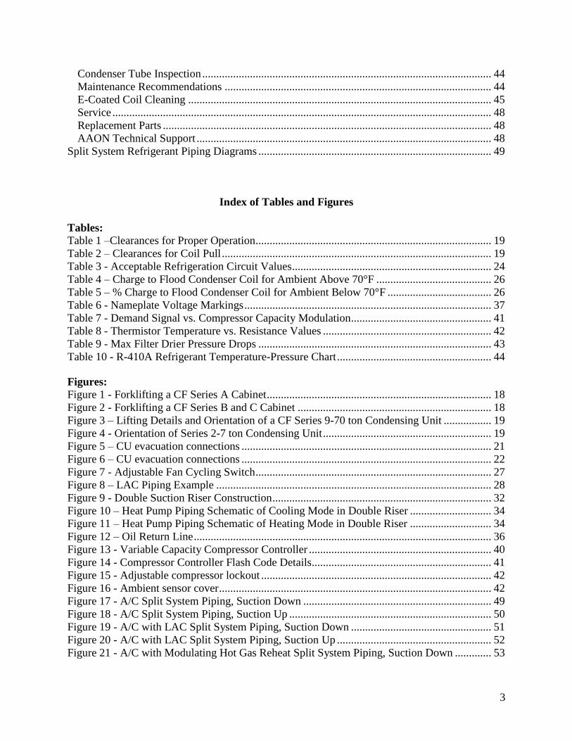
3
Condenser Tube Inspection 44 Maintenance Recommendations 44 E-Coated Coil Cleaning 45 Service 48
Replacement Parts 48 AAON Technical Support 48
Split System Refrigerant Piping Diagrams 49
Index of Tables and Figures
Tables
Table 1 ndashClearances for Proper Operation 19 Table 2 ndash Clearances for Coil Pull 19
Table 3 - Acceptable Refrigeration Circuit Values 24
Table 4 ndash Charge to Flood Condenser Coil for Ambient Above 70degF 26 Table 5 ndash Charge to Flood Condenser Coil for Ambient Below 70degF 26 Table 6 - Nameplate Voltage Markings 37
Table 7 - Demand Signal vs Compressor Capacity Modulation 41 Table 8 - Thermistor Temperature vs Resistance Values 42
Table 9 - Max Filter Drier Pressure Drops 43 Table 10 - R-410A Refrigerant Temperature-Pressure Chart 44
Figures
Figure 1 - Forklifting a CF Series A Cabinet 18
Figure 2 - Forklifting a CF Series B and C Cabinet 18 Figure 3 ndash Lifting Details and Orientation of a CF Series 9-70 ton Condensing Unit 19 Figure 4 - Orientation of Series 2-7 ton Condensing Unit 19
Figure 5 ndash CU evacuation connections 21 Figure 6 ndash CU evacuation connections 22
Figure 7 - Adjustable Fan Cycling Switch 27 Figure 8 ndash LAC Piping Example 28 Figure 9 - Double Suction Riser Construction 32 Figure 10 ndash Heat Pump Piping Schematic of Cooling Mode in Double Riser 34 Figure 11 ndash Heat Pump Piping Schematic of Heating Mode in Double Riser 34
Figure 12 ndash Oil Return Line 36 Figure 13 - Variable Capacity Compressor Controller 40
Figure 14 - Compressor Controller Flash Code Details 41 Figure 15 - Adjustable compressor lockout 42 Figure 16 - Ambient sensor cover 42 Figure 17 - AC Split System Piping Suction Down 49 Figure 18 - AC Split System Piping Suction Up 50
Figure 19 - AC with LAC Split System Piping Suction Down 51 Figure 20 - AC with LAC Split System Piping Suction Up 52 Figure 21 - AC with Modulating Hot Gas Reheat Split System Piping Suction Down 53
4
Figure 22 - AC with Modulating Hot Gas Reheat Split System Piping Suction Up 54 Figure 23 - AC with Modulating Hot Gas Reheat Split + LAC System Piping Suction Down 55 Figure 24 - AC with Modulating Hot Gas Reheat Split + LAC System Piping Suction Up 56 Figure 25 - AC with Hot Gas Bypass Split System Piping Suction Down 57
Figure 26 - AC with Hot Gas Bypass Split System Piping Suction Up 58 Figure 27 - AC with Hot Gas Bypass + LAC Split System Piping Suction Down 59 Figure 28 - AC with Hot Gas Bypass + LAC Split System Piping Suction Up 60 Figure 29 - AC with Modulating Hot Gas Reheat and Hot Gas Bypass Split System Piping
Suction Down 61
Figure 30 - AC with Modulating Hot Gas Reheat and Hot Gas Bypass Split System Piping
Suction Up 62 Figure 31 - AC with Modulating Hot Gas Reheat and Hot Gas Bypass + LAC Split System
Piping Suction Down 63
Figure 32 - AC with Modulating Hot Gas Reheat and Hot Gas Bypass + LAC Split System
Piping Suction Up 64
Figure 33 - Heat Pump Split System Piping Suction Down 65 Figure 34 - Heat Pump Split System Piping Suction Up 66
Figure 35 - Heat Pump with Modulating Hot Gas Reheat Split System Piping Suction Down 67 Figure 36 - Heat Pump with Modulating Hot Gas Reheat Split System Piping Suction Up 68 Figure 37 - Heat Pump with Hot Gas Bypass Split System Piping Suction Down 69
Figure 38 - Heat Pump with Hot Gas Bypass Split System Piping Suction Up 70 Figure 39 ndash Heat Pump with Modulating Hot Gas Reheat and Hot Gas Bypass Split System
Piping Suction Down 71 Figure 40 ndash Heat Pump with Modulating Hot Gas Reheat and Hot Gas Bypass Split System
Piping Suction Up 72
V45040 Rev A 190709
(ACP J00424)
5
AAON CF Series Features and Options Introduction
Energy Efficiency
bull Two-Stage 10-100 Variable Capacity
or Tandem R-410A Scroll Compressors
bull Air-Source Heat Pump
bull VFD Controlled ECM Driven and
ECM Low Sound Condenser Fans
Humidity Control bull Modulating Hot Gas Reheat
bull Makeup Air Applications up to 100
Outside Air
Safety bull Phase and Brownout Protection
bull Single Point Non-Fused Disconnect
Power Switch
bull Automatic Low Pressure and Manual
Reset High Pressure Safety Cut-outs
bull Adjustable Compressor Lockout
Installation and Maintenance bull Isolated Controls and Compressor
Compartment
bull Access Doors with Full Length Stainless
Steel Piano Hinges
bull Molded Lockable Handles
bull Color-Coded Wiring Diagrams
bull Run Test Report and Installation Manual
Included in Controls Compartment
bull Factory Installed Convenience Outlet
bull Service Access Lights
bull Remote StartStop Terminals
bull Liquid Line Sight Glass
bull Compressor Isolation Valves
System Integration bull Complete Split System with AAON DX
Air Handling Units
bull Remote Air-Cooled Condenser Option
bull Labeled Split System Piping Stub Outs
with Shut-Off Valves
bull Flooded Condenser 0degF Low Ambient
Controls
bull Terminal Block for Thermostat with
Isolation Relays
bull Constant Air Volume (CAV) Makeup
Air (MUA) Variable Air Volume
(VAV) and Single Zone Variable Air
Volume (SZ VAV)
Environmentally Friendly bull R-410A Refrigerant
Extended Life bull Optional 5 Year Compressor Warranty
bull G90 Galvanized Steel Construction
bull 2500 Hour Salt Spray Tested Exterior
Corrosion Protection
bull 10000 Hour Salt Spray Tested Polymer
E-Coated Condenser Coils
bull Copper Fin and Stainless Steel Casing
Coils
bull Condenser Coil Guards
bull Custom Color Paint Options
6
Safety
Attention should be paid to the following statements
NOTE - Notes are intended to clarify the unit installation operation and maintenance
CAUTION - Caution statements are given to prevent actions that may result in equipment
damage property damage or personal injury
WARNING - Warning statements are given to prevent actions that could result in
equipment damage property damage personal injury or death
DANGER - Danger statements are given to prevent actions that will result in equipment
damage property damage severe personal injury or death
QUALIFIED INSTALLER Improper installation adjustment alteration service or maintenance can cause property damage personal injury or loss of life Startup and service must be performed by a Factory Trained Service Technician A copy of this IOM should be kept with the unit
WARNING
ELECTRIC SHOCK Electric shock hazard Before servicing shut off all electrical power to the unit including remote disconnects to avoid shock hazard or injury from rotating parts Follow proper Lockout-Tagout procedures
WARNING
ELECTRIC SHOCK FIRE OR EXPLOSION HAZARD Failure to follow safety warnings exactly could result in dangerous operation serious injury death or property damage Improper servicing could result in dangerous operation serious injury death or property damage When servicing controls label all
wires prior to disconnecting Reconnect wires correctly
Verify proper operation after servicing Secure all doors with key-lock or nut and bolt
WARNING
7
ROTATING COMPONENTS Unit contains fans with moving parts that can cause serious injury Do not remove grill containing fans until the power to the unit has been disconnected and fan has stopped rotating
WARNING
LIVE ELECTRICAL During installation testing servicing and troubleshooting of the equipment it may be necessary to work with live electrical components Only a qualified licensed electrician or individual properly trained in handling live electrical components shall perform these tasks Standard NFPA-70E an OSHA regulation requiring an Arc Flash Boundary to be field established and marked for identification of where appropriate Personal Protective Equipment (PPE) be worn should be followed
WARNING
FIRE EXPLOSION OR CARBON MONOXIDE POISONING HAZARD Failure to replace proper controls could result in fire explosion or carbon monoxide poisoning Failure to follow safety warnings exactly could result in serious injury death or property damage Do not store or use gasoline or other flammable vapors and liquids in the vicinity of this appliance
WARNING
GROUNDING REQUIRED All field installed wiring must be completed by qualified personnel Field installed wiring must comply with NECCEC local and state electrical code requirements Failure to follow code requirements could result in serious injury or death Provide proper unit ground in accordance with these code requirements
WARNING
VARIABLE FREQUENCY DRIVES
Do not leave VFDs unattended in hand mode or manual bypass Damage to personnel or equipment can occur if left unattended When in hand mode or manual bypass mode VFDs will not respond to controls or alarms
WARNING
8
LEAK TESTING
Do not use oxygen acetylene or air in place of refrigerant and dry nitrogen for leak testing A violent explosion may result causing injury or death
WARNING
VARIABLE FREQUENCY DRIVES
Electric motor over-current protection and overload protection may be a function of the Variable Frequency Drive to which the motors are wired Never defeat the VFD motor overload feature The overload ampere setting must not exceed 115 of the electric motors FLA rating as shown on the motor nameplate
CAUTION
PVC PIPING
PVC (Polyvinyl Chloride) and CPVC (Chlorinated Polyvinyl Chloride) are vulnerable to attack by certain chemicals Polyolester (POE) oils used with R-410A and other refrigerants even in trace amounts in a PVC or CPVC piping system will result in stress cracking of the piping and fittings and complete piping system failure
CAUTION
3-PHASE ROTATION
Rotation must be checked on all MOTORS AND COMPRESSORS of 3 phase units at startup by a qualified service technician Scroll compressors are directional and can be damaged if rotated in the wrong direction Compressor rotation must be checked using suction and discharge gauges Fan motor rotation should be checked for proper operation Alterations should only be made at the unit power connection
CAUTION
UNIT HANDLING To prevent injury or death lifting equipment capacity shall exceed unit weight by an adequate safety factor Always test-lift unit not more than 24 inches high to verify proper center of gravity lift point to avoid unit damage injury or death
WARNING
DOOR LATCHES
Door compartments containing hazardous voltage or rotating parts are equipped with door latches that allow locks Door latches are shipped with a nut and bolt requiring tooled access If the shipping hardware is not replaced with a pad lock always re-install the nut and bolt after closing the door to maintain tooled access
CAUTION
9
ENCLOSED AREA
Do not work in an enclosed area where refrigerant or nitrogen gases may be leaking A sufficient quantity of vapors may be present and cause
injury or death
WARNING
COMPRESSOR LUBRICANT
Polyolester (POE) and Polyvinylether (PVE) oils are two types of lubricants used in hydrofluorocarbon (HFC) refrigeration systems Refer to the compressor label for the proper compressor lubricant type
CAUTION
COIL CLEANERS
To prevent damage to the unit do not use acidic chemical coil cleaners Do not use alkaline chemical coil cleaners with a pH value greater than 85 after mixing without first using an aluminum corrosion inhibitor in the cleaning solution
CAUTION
COIL CLEANERS
Some chemical coil cleaning compounds are caustic or toxic Use these substances only in accordance with the manufacturerrsquos usage instructions Failure to follow instructions may result in equipment damage injury or death
WARNING
COIL CLEANING
Do not clean DX refrigerant coils with hot water or steam The use of hot water or steam on refrigerant coils will cause high pressure inside the coil tubing and damage to the coil
CAUTION
CONVENIENCE OUTLETS
Factory installed convenience outlets are not intended for use while the unit is operating
WARNING
10
1 Startup and service must be performed by
a Factory Trained Service Technician
2 The unit is for outdoor use only See
General Information section for more
information
3 Every unit has a unique equipment
nameplate with electrical operational
and unit clearance specifications
Always refer to the unit nameplate for
specific ratings unique to the model
purchased
4 READ THE ENTIRE INSTALLATION
OPERATION AND MAINTENANCE
MANUAL OTHER IMPORTANT
SAFETY PRECAUTIONS ARE
PROVIDED THROUGHOUT THIS
MANUAL
5 Keep this manual and all literature
safeguarded near or on the unit
COMPRESSOR CYCLING
5 MINUTE MINIMUM OFF TIME To prevent motor overheating compressors must cycle off for a minimum of 5 minutes
5 MINUTE MINIMUM ON TIME To maintain the proper oil level compressors must cycle on for a minimum of 5 minutes The cycle rate must not exceed 6 starts per hour
WARNING
CF Series Feature String Nomenclature
Model Options Unit Feature Options G
EN
MJ
RE
V
SIZ
E
SE
RIE
S
MN
RE
V
VL
T
A1
A2
A3
A4
A5
1
2A
2B
3A
3B
4
5
6A
6B
6C
7
8A
8B
8C
8D
9
10
11
12
13
14
15
CF A - 015 - B - A - 3 - D C 0 0 K 0 - A 0 - E 0 - C 0 - A N 0 - B - D E 0 0 - 0 0 A 0 E 0 0
0 0 0 0 0 D B
16
17
18
19
20
21
22
11
CF Series Feature String Nomenclature
MODEL OPTIONS Series and Generation
CF
Major Revision
A
Unit Size
002 = 2 ton Capacity
003 = 3 ton Capacity
004 = 4 ton Capacity
005 = 5 ton Capacity
006 = 6 ton Capacity
007 = 7 ton Capacity
009 = 9 ton Capacity
011 = 11 ton Capacity
013 = 13 ton Capacity
015 = 15 ton Capacity
016 = 16 ton Capacity
018 = 18 ton Capacity
020 = 20 ton Capacity
025 = 25 ton Capacity
026 = 26 ton Capacity
030 = 30 ton Capacity
031 = 31 ton Capacity
040 = 40 ton Capacity
050 = 50 ton Capacity
060 = 60 ton Capacity
070 = 70 ton Capacity
Series
A = 2-7 ton units
B = 9-15 ton units
C = 16-25 amp 30 ton units
D = 26 amp 31-70 ton units
Minor Revision
A
Voltage
1 = 230V1Φ60Hz
2 = 230V3Φ60Hz
3 = 460V3Φ60Hz
4 = 575V3Φ60Hz
8 = 208V3Φ60Hz
9 = 208V1Φ60Hz
A1 Compressor Style
0 = Air-Cooled Condenser - No Compressors
(1 Circuit)
A = R-410A Scroll Compressors
B = R-410A Two Step Capacity Scroll Compressors
D = R-410A Variable Capacity Scroll Compressors
E = R-410A Tandem Scroll Compressors
G = R-410A Tandem Variable Capacity Scroll
Compressors
P = Air-Cooled Condenser - No Compressors
(2 Circuits)
Q = Air-Cooled Condenser - No Compressors
(4 Circuits)
A2 Condenser Style
C = Air-Cooled Condenser
J = Air-Source Heat Pump
A3 Configuration
0 = Standard
A4 Coating
0 = Standard
E = Polymer E-Coated Condenser Coil
G = Copper Fin + Stainless Steel Casing - Condenser
Coil
A5 Staging
0 = No Cooling
G = 1 OnOff Refrigeration System
H = 1 Variable Capacity Refrigeration System
J = 2 OnOff Refrigeration Systems
K = 1 Variable Capacity Refrigeration System + 1
OnOff Refrigeration System
L = 2 Variable Capacity Refrigeration System
R = 4 OnOff Refrigeration Systems
T = 2 Variable Capacity Refrigeration Systems + 2
OnOff Refrigeration Systems
U = 4 Variable Capacity Refrigeration Systems
CF Series Feature String Nomenclature
Model Options Unit Feature Options G
EN
MJR
EV
SIZ
E
SE
RIE
S
MN
RE
V
VL
T
A1
A2
A3
A4
A5
1
2A
2B
3A
3B
4
5
6A
6B
6C
7
8A
8B
8C
8D
9
10
11
12
13
14
15
CF A - 015 - B - A - 3 - D C 0 0 K 0 - A 0 - E 0 - C 0 - A N 0 - B - D E 0 0 - 0 0 A 0 E 0 0
0 0 0 0 0 D B
16
17
18
19
20
21
22
12
UNIT FEATURE OPTIONS 1 Unit Orientation
0 = Vertical Condenser Discharge - Standard Access
A = Horizontal Condenser Discharge - Standard
Access
2A Refrigeration Control
0 = Standard
A = 5 Minute Compressor Off Timer + 20 Second
Compressor Stage Delay
C = Adjustable Fan Cycling
D = Adjustable Compressor Lockout
G = Option A + Adjustable Fan Cycling
H = Option A + Adjustable Compressor Lockout
M = Adjustable Fan Cycling + Adjustable
Compressor Lockout
W = Option A + Adjustable Fan Cycling +
Adjustable Compressor Lockout
2B Blank
0 = Standard
3A Refrigeration Options
0 = Standard
A = Hot Gas Bypass Lead Stage [HGB]
B = HGB Lead + HGB Lag
D = Hot Gas Bypass Non-Variable Capacity
Refrigeration Systems [HGBNV]
E = Modulating Hot Gas Reheat [MHGR]
H = HGB + MHGR
J = HGB Lead + HGB Lag + MHGR
L = HGBNV + MHGR
3B Blank
0 = Standard
4 Refrigeration Accessories
0 = Standard
A = Sight Glass
B = Compressor Isolation Valves
C = Options A + B
D = Flooded Condenser 0degF Low Ambient Controls ndash
One Circuit
E = Options A + D
F = Options B + D
G = Options A + B + D
H = Flooded Condenser 0degF Low Ambient Controls-
Two Circuits
J = Options A + H
K = Options B + H
L = Options A + B + H
R = Flooded Condenser 0degF Low Ambient Controls ndash
Four Circuits
S = Options A + R
T = Options B + R
U = Options A + B + R
5 Blank
0 = Standard
6A Unit Disconnect Type
0 = Single Point Power Block
A = Single Point Power Non-Fused Disconnect
6B Disconnect 1 Size
0 = Standard
N = 100 amps
R = 150 amps
V = 250 amps
Z = 400 amps
6C Blank
0 = Standard
CF Series Feature String Nomenclature
Model Options Unit Feature Options
GE
N
MJR
EV
SIZ
E
SE
RIE
S
MN
RE
V
VL
T
A1
A2
A3
A4
A5
1
2A
2B
3A
3B
4
5
6A
6B
6C
7
8A
8B
8
C
8D
9
10
11
12
13
14
15
CF A - 015 - B - 0 - 3 - D C 0 0 K 0 - A 0 - E 0 - C 0 - A N 0 - B - D C 0 0 - 0 0 A 0 E 0 0 0 0 0 0 0 D B
16
17
18
19
20
21
22
13
7 Accessories
0 = Standard
B = Phase amp Brown Out Protection
D = Suction Pressure Transducer on Each
Refrigeration Circuit
E = Compressor Sound Blanket
L = Options B + D
M = Options B + E
Q = Options D + E
1 = Options B + D + E
8A Control Sequence
A = Terminal Block for Thermostat w Isolation
Relays
D = VAV Unit Controller - VAV Cool + CAV Heat
E = CAV Unit Controller
F = Makeup Air Unit Controller - CAV Cool + CAV
Heat
H = Constant Volume HP Unit Controller - CAV
Cool + CAV Heat
J = Makeup Air HP Unit Controller - CAV Cool +
CAV Heat
N = Field Installed DDC Controls by Others with
Isolation Relays
8B Control Suppliers
0 = Standard
E = Orion VCC-X (Main Controller in Air Handling
Unit)
H = AAON Touchscreen Controller (Main Controller
in Air Handling Unit)
8C Control Supplier Options
0 = Standard
8D BMS Connection amp Diagnostics
0 = Standard
9 Blank
0 = Standard
10 Blank
0 = Standard
11 Maintenance Accessories
0 = Standard
A = Factory Wired 115VAC Convenience Outlet
B = Field Wired 115VAC Convenience Outlet
C = Service Lights
E = Remote Unit StartStop Terminals
F = Options A + C
H = Options A + E
J = Options B + C
L = Options B + E
N = Options C + E
R = Options A + C + E
U = Options B + C + E
12 Code Options
0 = Standard ETL USA Listing
B = ETL USA + Canada Listing
13 Air-Cooled Condenser Accessories
0 = Standard
A = Condenser Coil Guard
C = ECM Condenser Fan Head Pressure Control
E = VFD Condenser Fan Head Pressure Control
G = Options A + C
J = Options A + E
N = ECM Condenser Fan Head Pressure Control +
Low Sound Condenser Fan
S = Options A + N
14 Blank
0 = Standard
15 Blank
0 = Standard
16 Electrical Options
0 = Standard
17 Shipping Options
0 = Standard
A = Crating
B = Export Crating
CF Series Feature String Nomenclature
Model Options Unit Feature Options G
EN
MJR
EV
SIZ
E
SE
RIE
S
MN
RE
V
VL
T
A1
A2
A3
A4
A5
1
2A
2B
3A
3B
4
5
6A
6B
6C
7
8A
8B
8C
8D
9
10
11
12
13
14
15
CF A - 015 - B - A - 3 - D C 0 0 K 0 - A 0 - E 0 - C 0 - A N 0 - B - D E 0 0 - 0 0 A 0 E 0 0
0 0 0 0 0 D B 1
6
17
18
19
20
21
22
14
18 Blank
0 = Standard
19 Blank
0 = Standard
20 Cabinet Material
0 = Galvanized Steel Cabinet
21 Warranty
0 = Standard
D = Compressor Warranty - Years 2-5
22 Type
B = Premium AAON Gray Paint Exterior
E = Premium AAON Gray Paint Ext + Shrink Wrap
X = SPA + Premium AAON Gray Paint Exterior
1 = SPA + Premium AAON Gray Paint Exterior +
Shrink Wrap
15
General Information
AAON CF Series air-cooled condensers and
condensing units have been designed for
outdoor use only They are factory
assembled wired charged and run-tested
Codes and Ordinances
CF Series units have been tested and
certified by ETL in accordance with UL
Safety Standard 1995CSA C222 No 236
System should be sized in accordance with
the American Society of Heating
Refrigeration and Air Conditioning
Engineers Handbook
Installation of CF Series units must conform
to the ICC standards of the International
Mechanical Code the International Building
Code and local building plumbing and
electrical codes All appliances must be
electrically grounded in accordance with
local codes or in the absence of local codes
the current National Electric Code
ANSINFPA 70 or the current Canadian
Electrical Code CSA C221
Receiving Unit
When received the unit should be checked
for damage that might have occurred in
transit If damage is found it should be noted
on the carrierrsquos freight bill A request for
inspection by carrierrsquos agent should be made
in writing at once Nameplate should be
checked to ensure the correct model sizes and
voltages have been received to match the job
requirements
If repairs must be made to damaged goods
then the factory should be notified before any
repair action is taken in order to protect the
warranty Certain equipment alteration
repair and manipulation of equipment
without the manufacturerrsquos consent may void
the product warranty Contact AAON
Technical Support for assistance with
handling damaged goods repairs and freight
claims (918) 382-6450
SHARP EDGES
Coils and sheet metal surfaces present sharp edges and care must be taken when working with equipment
WARNING
QUALIFIED INSTALLER
Improper installation adjustment alteration service or maintenance can cause property damage personal injury or loss of life Installation and service must be performed by a Factory Trained Service Technician
WARNING
Failure to observe the following instructions will result in premature failure of your system and possible voiding of the warranty
WARNING
16
Storage
If installation will not occur immediately
following delivery store equipment in a dry
protected area away from construction traffic
and in the proper orientation as marked on the
packaging with all internal packaging in
place Secure all loose-shipped items
Failure to observe the following instructions
will result in premature failure of your
system and possible voiding of the warranty
Never turn off the main power supply to the
unit except for complete shutdown When
power is cut off from the unit any
compressors using crankcase heaters cannot
prevent refrigerant migration This means the
compressor will cool down and liquid
refrigerant may accumulate in the
compressor The compressor is designed to
pump refrigerant gas and damage may occur
if liquid enters the compressor when power is
restored
Before unit operation the main power switch
must be turned on for at least twenty-four
hours for units with compressor crankcase
heaters This will give the crankcase heater
time to clear any liquid accumulation out of
the compressor before it is required to run
Always control the system from the control
panel never at the main power supply (except
for emergency or for complete shutdown of
the system)
CLEAN AIR ACT
The Clean Air Act of 1990 bans the intentional venting of refrigerant as of July 1 1992 Approved methods of recovery recycling or reclaiming must be followed
CAUTION
CRANKCASE HEATER OPERATION
Units are equipped with compressor crankcase heaters which should be energized at least 24 hours prior to cooling operation to clear any liquid refrigerant from the compressors
CAUTION
3-PHASE ROTATION
Rotation must be checked on all MOTORS AND COMPRESSORS of three phase units All motors to include and not be limited to pump motors and condenser fan motors should all be checked by a qualified service technician at startup and any wiring alteration should only be made at the unit power connection
CAUTION
17
The standard compressors must be on a
minimum of 5 minutes and off for a minimum
of 5 minutes The cycle rate must be no more
than 6 starts per hour
The variable capacity compressors must be
on a minimum of 3 minutes and off for a
minimum of 3 minutes The cycle rate must
be no more than 6 starts per hour
The compressor life will be seriously
shortened by reduced lubrication and the
pumping of excessive amounts of liquid oil
and liquid refrigerant
Wiring Diagrams
A complete set of unit specific wiring
diagram in point-to-point form is laminated
in plastic and located inside the control
compartment door
General Maintenance
When the initial startup is made and on a
periodic schedule during operation it is
necessary to perform routine service checks
on the performance of the condensing unit
This includes reading and recording suction
pressures and checking for normal sub-
cooling and superheat
COMPRESSOR ROTATION
Scroll compressors are directional and will be damaged by operation in the wrong direction Low pressure switches on compressors have been disconnected after factory testing Rotation should be checked by a qualified service technician at startup using suction and discharge pressure gauges and any wiring alteration should only be made at the unit power connection
COMPRESSOR CYCLING
5 MINUTE MINIMUM OFF TIME To prevent motor overheating compressors must cycle off for a minimum of 5 minutes
5 MINUTE MINIMUM ON TIME To maintain the proper oil level compressors must cycle on for a minimum of 5 minutes The cycle rate must not exceed 6 starts per hour
WARNING
CAUTION
18
Installation
Forklifting the Unit
CF Series condensing unit sizes 2-25 amp 30
tons can be lifted using a forklift 2-7 ton
units must have forks at least 48rdquo in length
9-25 amp 30 ton units must have forks 72rdquo in
length or the forks must have 72rdquo fork
extensions Standard units can be lifted from
all sides except the condenser coil side CF
Series condensing unit sizes 26 amp 31-70 tons
cannot be lifted using a forklift They can be
lifted as shown in Figure 3
Forks must be perpendicular to the unit and
they must be in far enough that the back of
the forks are no more than 6rdquo away from the
edge of the unit
Figure 1 - Forklifting a CF Series A Cabinet
Figure 2 - Forklifting a CF Series B and C
Cabinet
FORKLIFTING 2-7 TON UNITS
Forks or Fork Extensions must be at least 48rdquo in length
CAUTION
FORKLIFTING 9-25 amp 30 TON UNITS
Forks or Fork Extensions must be at least 72rdquo in length
CAUTION
19
Lifting the Unit
If cables or chains are used to hoist the unit
they must be the same length Minimum
cable length is 99rdquo for CF Series 9-70 ton
units CF Series 2-7 ton units do not include
factory installed lifting lugs and should be
lifted by forklift only Care should be taken
to prevent damage to the cabinet coils and
condenser fans
Before lifting unit be sure that all shipping
material has been removed from unit Secure
hooks and cables at all lifting points lugs
provided on the unit
Figure 3 ndash Lifting Details and Orientation of
a CF Series 9-70 ton Condensing Unit
Locating the Unit
The CF Series condenser and condensing unit
is designed for outdoor applications and
mounting at ground level or on a rooftop It
must be placed on a level and solid
foundation that has been prepared to support
its weight When installed at ground level a
one-piece concrete slab should be used with
footings that extend below the frost line Also
with ground level installation care must be
taken to protect the coil fins from damage due
to vandalism or other causes
The first clearance table below gives the
clearance values for proper unit operation
The second clearance table gives the
clearance necessary for removing the coil
without disassembling a large part of the
condensing unit For ease of removing the
condenser coil use the second table
clearances for the right hand side of the unit
Table 1 ndashClearances for Proper Operation
Location Unit Size
2-7 tons 9-70 tons
Front -
(Controls
Side)
Unobstructed 36rdquo
Left Side 6rdquo 30rdquo
Right Side 6rdquo 36rdquo
Top 3rdquo Unobstructed
Back 18rdquo 6rdquo
Table 2 ndash Clearances for Coil Pull
Unit Size Right Hand Side
2-7 tons 42rdquo
9-15 tons 42rdquo
16-25 amp 30 tons 54rdquo
26 amp 31-70 tons 66rdquo
Figure 4 - Orientation of Series 2-7 ton
Condensing Unit
20
The placement relative to the building air
intakes and other structures must be carefully
selected Airflow to and from the condenser
or condensing unit must not be restricted to
prevent a decrease in performance and
efficiency
The installation position for 9-70 ton units
must provide at least 30rdquo of left and right side
clearance for proper airflow to the condenser
coils When units are mounted adjacent to
each other the minimum right and left side
clearance required between the units is 60rdquo or
5 feet Similarly when 2-7 ton units are
mounted adjacent to each other the minimum
clearance required between the back side of
the units is 36rdquo or 3 feet
Units should not be installed in an enclosure
or pit that is deeper than the height of the unit
When recessed installation is necessary the
clearance to maintain proper airflow is at
least 5 feet (3 feet for 2-7tons)
CF Series condensers and condensing units
that have a vertical air discharge must have
no obstruction above the equipment Do not
place the unit under an overhang CF Series
condensers and condensing units that have a
horizontal discharge must have no
obstruction in front of the unit
For proper unit operation the immediate area
around condenser must remain free of debris
that may be drawn in and obstruct airflow in
the condensing section
Consideration must be given to obstruction
caused by snow accumulation when placing
the unit
Mounting Isolation
For roof mounted applications or anytime
vibration transmission is a factor vibration
isolators may be used
Access Doors
Access doors are provided to the compressor
and electrical compartment
Standard Evacuation Instructions
Proper system evacuation is critical to
remove moisture and non-condensables from
the system before charging the system with
refrigerant A newly installed AAON
condensing unit has already been evacuated
and charged with some refrigerant at the
factory When evacuating a new system
keep the condensing unit service valves
closed and evacuate the suction and liquid
lines and the air handling unit If the entire
system must be evacuated use the following
procedure to ensure the entire system is
pulled into a good vacuum
1 System evacuation should be
performed anytime a system is open to
atmospheric pressure The POE oils
used with R-410A are extremely
hydroscopic in nature and immediately
begin pulling in moisture once the
system is opened to the atmosphere
2 Before starting to evacuate the
system you MUST ensure that there are
no leaks by pressurizing the system with
PVC PIPING
PVC (Polyvinyl Chloride) and CPVC (Chlorinated Polyvinyl Chloride) are vulnerable to attack by certain chemicals Polyolester (POE) oils used with R-410A and other refrigerants even in trace amounts in a PVC or CPVC piping system will result in stress cracking of the piping and fittings and complete piping system failure
CAUTION
21
400 psig of dry nitrogen and verifying no
pressure loss after one hour
3 Four valve manifold gauge sets are
more effective than standard manifold
gauge sets due to the extra hose port in
combination with a 38rsquorsquo evacuation
port The larger diameter evacuation port
will expedite system evacuation
4 The manifold set should be connected
to the condensing unit with one hose on
the suction line service valve one hose
on the liquid line service valve and if an
extra Schrader valve is field installed on
the suction line connect a third hose (not
shown) The vacuum pump should be
connected to the manifold set using a
38rdquo vacuum rated hose Figure 5 shows
two circuits Both circuits must be
evacuated separately
Figure 5 ndash CU evacuation connections
5 An accurate micron gauge must be
used and checked by pulling a vacuum
on the gauge by itself and verify a rapid
drop to less than 100 microns within a
few minutes
6 The micron gauge should not be
attached to the system until the gauge
manifold is reading 28rsquorsquo of vacuum to
ensure the micron gauge does not see
pressure and is thus damaged MICRON
GAUGES WILL BE DAMAGED BY
PRESSURE
7 It is a good practice to replace the
vacuum pump oil after one hour of the
evacuation process The oil can be
broken down in the pump in the initial
first hour causing system evacuation to
take longer than it should
8 The minimum micron level required
by AAON is 350 microns for systems
using POE oils
9 The system should then be isolated
and the pump turned off to check for
vacuum rise due to leaks or moisture in
the system The micron gauge should
not rise above 500 microns after 30
minutes of wait time
Low Ambient amp Modulating Reheat
System Evacuation Instructions
Proper system evacuation is critical to
remove moisture and non-condensables from
the system before charging the system with
refrigerant Systems with low ambient
flooded condenser option require the
following procedure to ensure the entire
system is pulled into a good vacuum
1 System evacuation should be
performed anytime a system is open to
atmospheric pressure The POE oils
used with R-410A are extremely
hydroscopic in nature and immediately
begin pulling in moisture once the
system is opened to the atmosphere
2 Open the reheat valve to 50 when
evacuating
3 Before starting to evacuate the
system you MUST ensure that there are
no leaks by pressurizing the system with
22
400 psig of dry nitrogen and verifying no
pressure loss after one hour
4 Four valve manifold gauge sets are
more effective than standard manifold
gauge sets due to the extra hose port in
combination with a 38rsquorsquo evacuation
port The larger diameter evacuation port
will expedite system evacuation
5 The manifold set should be connected
to the condensing unit with one hose on
the suction line service valve one hose
on the liquid line service valve and a
third hose on the reheat line service
valve The vacuum pump should be
connected to the manifold set using a
38rdquo vacuum rated hose Figure 6 shows
two circuits The first circuit has a
reheat line the second circuit is just the
suction and liquid line Both circuits
must be evacuated separately
Figure 6 ndash CU evacuation connections
6 FAILURE to connect to the liquid
line service valve will result in the
receiver tank not being fully evacuated
and most likely lead to non-
condensables in the system
7 An accurate micron gauge must be
used and checked by pulling a vacuum
on the gauge by itself and verify a rapid
drop to less than 100 microns within a
few minutes
8 The micron gauge should not be
attached to the system until the gauge
manifold is reading 28rsquorsquo of vacuum to
ensure the micron gauge does not see
pressure and is thus damaged MICRON
GAUGES WILL BE DAMAGED BY
PRESSURE
9 It is a good practice to replace the
vacuum pump oil after one hour of the
evacuation process The oil can be
broken down in the pump in the initial
first hour causing system evacuation to
take longer than it should
10 The minimum micron level required
by AAON is 350 microns for systems
using POE oils
11 The system should then be isolated
and the pump turned off to check for
vacuum rise due to leaks or moisture in
the system The micron gauge should
not rise above 500 microns after 30
minutes of wait time
Adjusting Refrigerant Charge
All AAON CF Series condensers and
condensing units are shipped with a factory
holding charge The factory charge is
different depending on the unit size and
system (heat pump modulating hot gas
reheat LAC) The factory charge per circuit
is shown on the unit nameplate Adjusting the
charge of the system will be required during
installation
23
Adjusting the charge of a system in the field
must be based on determination of liquid sub-
cooling and evaporator superheat On a
system with a thermostatic expansion valve
liquid sub-cooling is more representative of
the charge than evaporator superheat but both
measurements must be taken
Before Charging
Refer to the Unit Nameplate to determine
which refrigerant must be used to charge the
system
Unit being charged must be at or near full
load conditions before adjusting the charge
Units equipped with hot gas bypass must
have the hot gas bypass valve closed to get
the proper charge
Units equipped with hot gas reheat must be
charged with the hot gas valve closed while
the unit is in cooling mode After charging
unit should be operated in reheat
(dehumidification) mode to check for correct
operation
Units equipped with heat pump options
should be charged in cooling mode to get the
proper charge After charging unit should be
operated in heating mode to check for correct
charge Charge may need to be adjusted for
heating mode If adjustments are made in the
heating mode cooling mode must be rerun to
verify proper operation
After adding or removing charge the system
must be allowed to stabilize typically 10-15
minutes before making any other
adjustments
The type of unit and options determine the
ranges for liquid sub-cooling and evaporator
superheat Refer to Table 3 when determining
the proper sub-cooling
For units equipped with low ambient (0degF)
option see the special charging instructions at
the end of this section
Checking Liquid Sub-cooling
Measure the temperature of the liquid line as
it leaves the condenser coil
Read the gauge pressure at the liquid line
close to the point where the temperature was
taken You must use liquid line pressure as it
will vary from discharge pressure due to
condenser coil pressure drop
Convert the pressure obtained to a saturated
temperature using the appropriate refrigerant
temperature-pressure chart
COMPRESSOR LUBRICANT
Polyolester (POE) and Polyvinylether (PVE) oils are two types of lubricants used in hydrofluorocarbon (HFC) refrigeration systems Refer to the compressor label for the proper compressor lubricant type
CAUTION
CLEAN AIR ACT
The Clean Air Act of 1990 bans the intentional venting of refrigerant (CFCrsquos and HCFCrsquos) as of July 1 1992 Approved methods of recovery recycling or reclaiming must be followed Fines andor incarceration may be levied for non-compliance
CAUTION
24
Subtract the measured liquid line temperature
from the saturated temperature to determine
the liquid sub-cooling
Compare calculated sub-cooling to Table 3
for the appropriate unit type and options
Table 3 - Acceptable Refrigeration Circuit
Values
Cooling
Mode
Liquid Sub-
Cooling
Values
Cooling Only Unit4 8-15degF
Cooling Only Unit with Hot
Gas Reheat14 5-15degF
Heat PumpUnit24 2-4degF
Heat Pump Unit with Hot
Gas Reheat34 2-6degF
Cooling Only Unit with
LAC4 8-15degF
Cooling Only Unit with Hot
Gas Reheat amp LAC4 8-15degF
Notes 1 Must be charged with the hot gas valve
closed After charging unit should be
operated in reheat (dehumidification) mode
to check for correct operation
2 The sub-cooling value in this table is for the
unit running in cooling mode of operation
After charging unit should be operated in
heating mode to check for correct operation
3 The sub-cooling value in this table is for the
unit running in cooling mode of operation
and the hot gas valve closed After charging
unit should be operated in reheat
(dehumidification) mode to check for correct
operation and then in heating mode to check
for correct operation
4 Sub-cooling must be increased by 1degF per 10
feet of vertical liquid line rise for R-410A
(AHU above CU) For example a cooling
only unit with hot gas reheat and a vertical
liquid drop can charge to a sub-cooling value
of 5-15degF but a cooling only unit with hot
gas reheat and a vertical liquid rise of 30 ft
must charge to a sub-cooling value of at least
8-15degF DO NOT OVERCHARGE
Refrigerant overcharging leads to excess
refrigerant in the condenser coils resulting in
elevated compressor discharge pressure
Checking Evaporator Superheat
Measure the temperature of the suction line
close to the compressor
Read gauge pressure at the suction line close
to the compressor
Convert the pressure obtained to a saturated
temperature using the appropriate refrigerant
temperature-pressure chart
Subtract the saturated temperature from the
measured suction line temperature to
determine the evaporator superheat
For refrigeration systems with tandem
compressors it is critical that the suction
superheat setpoint on the TXV is set with one
compressor running The suction superheat
should be 10-13degF with one compressor
running The suction superheat will increase
with both compressors in a tandem running
Inadequate suction superheat can allow liquid
refrigerant to return to the compressors which
will wash the oil out of the compressor Lack
of oil lubrication will destroy a compressor
Liquid sub-cooling should be measured with
both compressors in a refrigeration system
running
Compare calculated superheat to the
acceptable cooling mode superheat values of
8-15degF for all system types Superheat will
increase with long suction line runs
25
Adjusting Sub-cooling and Superheat
Temperatures
The system is overcharged if the sub-cooling
temperature is too high compared to Table 3
and the evaporator is fully loaded (low loads
on the evaporator result in increased sub-
cooling) and the evaporator superheat is
within the temperature range of 8-15degF (high
superheat results in increased sub-cooling)
Correct an overcharged system by reducing
the amount of refrigerant in the system to
lower the sub-cooling
The system is undercharged if the superheat
is too high and the sub-cooling is too low
Correct an undercharged system by adding
refrigerant to the system to reduce superheat
and raise sub-cooling
If the sub-cooling is correct and the superheat
is too high the TXV may need adjustment to
correct the superheat
DO NOT OVERCHARGE Refrigerant overcharging leads to excess refrigerant in the condenser coils resulting in elevated compressor discharge pressure
CAUTION
EXPANSION VALVE ADJUSTMENT
Thermal expansion valves must be adjusted to approximately 8-15degF of suction superheat Failure to have sufficient superheat will damage the compressor and void the warranty
CAUTION
26
Special Low Ambient Option Charging
Instructions
For units equipped with low ambient
refrigerant flood back option being charged
in the summer when the ambient
temperature is warm
If the ambient is above 70degF charge to
approximately 1-2degF of sub-cooling
measured at the inlet to the expansion valve
Once enough charge has been added to get
the evaporator superheat and sub-cooling
values to the correct setting more charge
must be added Use Table 4 to find the
additional charge amount required for the
system when running in cold ambient
conditions
Table 4 ndash Charge to Flood Condenser Coil
for Ambient Above 70degF
CF Size of
circuits
Per Circuit
Charge (lbs)
CF 2 3 1 49
CF 4 5 6 7 1 92
CF 9 11 2 91
CF 13 15 2 121
CF 16 18 2 131
CF 20 25 30 2 175
CF 26 31 40 2 180
4 91
CF 50 60 70 2 438
4 221
For units equipped with low ambient
refrigerant flood back option being charged
in the winter when the ambient
temperature is cold
1 If the ambient is below 70degF charge
to approximately 1-2degF of sub-cooling
measured at the inlet to the expansion
valve Once enough charge has been
added to get the evaporator superheat
and sub-cooling values to the correct
setting more charge may need to be
added If the ambient temperature is 0degF
no more charge is required Ambient
temperatures above 0degF will require a
percentage of the per circuit charge
values from Table 4 Using your
ambient temperature find the
percentage value from Table 5 and
multiply the Per Circuit Charge value
from Table 4 and the value to
determine the additional charge amount
Table 5 ndash Charge to Flood Condenser
Coil for Ambient Below 70degF
Condenser
Ambient
Temperature ˚F
Percentage
Per Circuit
Charge from
Table 4
60 60
50 37
40 24
30 15
20 8
0 0
2 The unit should be checked for proper
operation once the ambient temperature
is above 80degF
Example A CF size 31 with tandem
compressors where the ambient
temperature is 40degF
From Table 4 ndash 18 lbs refrigerant charge
per circuit (tandem compressors would
have 2 circuits in this size of CF)
From Table 5 ndash 24 of Table 4 charge
Additional charge needed for a unit with
low ambient flooded condenser controls
= 18 lbs 024 = 432 lbs additional
refrigerant charge per circuit
27
Low Ambient Operation
During low ambient temperatures the vapor
refrigerant will migrate to the cold part of the
system and condense into liquid All CF
Series compressors are provided with factory
installed crankcase heaters to help prevent
liquid refrigerant from slugging the
compressors during startup in low ambient
conditions The condenser or condensing unit
must have continuous power 24 hours prior
to startup This ensures the compressor will
receive sufficient refrigerant vapor at startup
Standard units can operate down to 55degF
ambient temperature
AAON condenser fan head pressure control
units can operate down to 35degF ambient
temperature Three different condenser fan
head pressure control options available are
adjustable fan cycling ECM condenser fan
or VFD controlled condenser fans See
detailed information following
The AAON low ambient (condenser flood-
back) system is used to operate a refrigerant
system down to 0degF outside air temperature
See detailed information following
Fan Cycling Low Ambient
Adjustable fan cycling is a low ambient head
pressure control option that cycles the
condenser fans to maintain refrigerant circuit
head pressures at acceptable levels during
cooling operation The head pressure set
point (100-470 psi) and pressure differential
(35-200 psi) can be field adjusted using a
flathead screwdriver For example if the
head pressure is set to 300psi and the
differential is set to 100psi then fans will cut
in at 300psi and cut out at 200psi Fan
cycling and variable speed condenser fan
head pressure control options allow
mechanical cooling with ambient
temperatures down to 35degF
Figure 7 - Adjustable Fan Cycling Switch
Variable Speed Low Ambient
Variable speed condenser fan head pressure
control is a low ambient head pressure
control option that sends a variable signal in
relation to the refrigerant circuit head
pressure of the system to an electronically
commutated motor (ECM) or VFD The
motor either speeds up or slows down air
flow accordingly in order to maintain
constant head pressure Fan cycling and
variable speed condenser fan head pressure
control options allow mechanical cooling
with ambient temperatures down to 35degF
Flooded Condenser Low Ambient
Flooded condenser low ambient control
maintains normal head pressure during
periods of low ambient When the ambient
temperature drops the condensing
temperature and therefore pressure drops
Without ambient control the system would
shut down on low discharge pressure The
flooded condenser method of low ambient
control fills the condenser coil with liquid
refrigerant decreasing the heat transfer
capacity of the coil which allows the coil to
operate at an acceptable discharge pressure
28
The condenser coil will not be flooded during
summer ambient temperatures so a receiver
is included to store the additional liquid
refrigerant required to flood the condenser
coil in low ambient The receiver is factory-
sized to contain all of the flooded volume
Without a receiver there would be high head
pressures during higher ambient conditions
The low ambient system maintains normal
head pressure during periods of low ambient
by restricting liquid flow from the condenser
to the receiver and at the same time
bypassing hot gas around the condenser to the
inlet of the receiver This reduces liquid
refrigerant flow from the condenser reducing
its effective surface area which in turn
increases the condensing pressure At the
same time the bypassed hot gas raises liquid
pressure in the receiver allowing the system
to operate properly CF Series condensers
and condensing units use an LAC valve for
low ambient operation
LAC Valve
The Low Ambient Control (LAC) valve is a
non-adjustable three way valve that
modulates to maintain receiver pressure As
the receiver pressure drops below the valve
setting (295 psig for R-410A) the valve
modulates to bypass discharge gas around the
condenser The discharge gas warms the
liquid in the receiver and raises the pressure
to the valve setting The following schematic
shows an example system using the LAC
valve
Figure 8 ndash LAC Piping Example
29
Refrigerant Piping
(See back of the manual for refrigerant piping
diagrams)
General
Piping from the condensing unit to the air
handler is the responsibility of the installing
contractor
Use only clean type ldquoACRrdquo copper tubing
that has been joined with high temperature
brazing alloy
The pipe or line sizes must be selected to
meet the actual installation conditions and
NOT simply based on the connection sizes at
the condensing unit or air handler
All CF Series condensing units are provided
with in-line shutoff valves on both the liquid
and suction lines These should remain closed
until the system is ready for start-up after
installation
Piping should conform to generally accepted
practices and codes
Care must be taken not to cross the circuits
on multiple circuit systems
Upon completion of piping connection the
interconnecting piping and air handler MUST
BE evacuated to 500 microns or less leak
checked and charged with refrigerant
Determining Refrigerant Line Size
The piping between the condenser and low
side must ensure
1 Minimum pressure drop and
2 Continuous oil return and
3 Prevention of liquid refrigerant slugging
or carryover
Minimizing the refrigerant line size is
favorable from an economic perspective
reducing installation costs and reducing the
potential for leakage However as pipe
diameters decrease pressure drop increases
Excessive suction line pressure drop causes
loss of compressor capacity and increased
power usage resulting in reduced system
efficiency Excessive pressure drops in the
liquid line can cause the liquid refrigerant to
flash resulting in faulty TXV operation and
improper system performance In order to
operate efficiently and cost effectively while
avoiding malfunction refrigeration systems
must be designed to minimize both cost and
pressure loss
REFRIGERANT PIPING
Line sizes must be selected to meet actual installation conditions not simply based on the connection sizes at the condensing unit or air handling unit
CAUTION
REFRIGERANT PIPING
This section is for information only and is not intended to provide all details required by the designer or installer of the refrigerant piping between the condenser or condensing unit and the air handling unit AAON Inc is not responsible for interconnecting refrigerant piping Consult ASHRAE Handbook ndash Refrigeration and ASME Standards
CAUTION
30
Equivalent Line Length
All line lengths discussed in this manual
unless specifically stated otherwise are
Equivalent Line Lengths The frictional
pressure drop through valves fittings and
accessories is determined by establishing the
equivalent length of straight pipe of the same
diameter Always use equivalent line
lengths when calculating pressure drop
Special piping provisions must be taken
when lines are up vertical risers or in
excessively long line runs AAON does not
recommend running underground
refrigerant lines
Liquid Line
When sizing the liquid line it is important to
minimize the refrigerant charge to reduce
installation costs and improve system
reliability This can be achieved by
minimizing the liquid line diameter
However reducing the pipe diameter will
increase the velocity of the liquid refrigerant
which increases the frictional pressure drop
in the liquid line and causes other
undesirable effects such as noise
Maintaining the pressure in the liquid line is
critical to ensuring sufficient saturation
temperature avoiding flashing upstream of
the TXV and maintaining system efficiency
Pressure losses through the liquid line due to
frictional contact installed accessories and
vertical risers are inevitable Maintaining
adequate sub-cooling at the condenser to
overcome these losses is the only method to
ensure that liquid refrigerant reaches the
TXV
Liquid refrigerant traveling upwards in a riser
loses head pressure If the evaporator is
below the condenser with the liquid line
flowing down the gravitational force will
increase the pressure of the liquid refrigerant
This will allow the refrigerant to withstand
greater frictional losses without the
occurrence of flashing prior to the TXV
A moisture-indicating sight glass may be
field installed in the liquid line to indicate the
occurrence of premature flashing or moisture
in the line The sight glass should not be used
to determine if the system is properly
charged Use temperature and pressure
measurements to determine liquid sub-
cooling not the sight glass
Liquid Line Routing
Care should be taken with vertical risers
When the system is shut down gravity will
pull liquid down the vertical column and
back to the condenser when it is below the
evaporator This could potentially result in
compressor flooding A check valve can be
installed in the liquid line where the liquid
column rises above the condenser to prevent
this The liquid line is typically pitched along
with the suction line or hot gas line to
minimize the complexity of the
configuration
Liquid Line Insulation
In cooling only systems when the liquid line
is routed through regions where temperature
losses are expected no insulation is required
as this may provide additional sub-cooling to
the refrigerant When routing the liquid line
through high temperature areas insulation of
the line is appropriate to avoid loss of sub-
cooling through heat gain
In heat pump systems when the liquid line is
routed through regions where temperature
losses are expected (all lines exposed to
outside air conditions) insulate with a
minimum 1 inch thick Armaflex insulation
as this will prevent capacity loss during
heating mode of operation
31
Liquid Line Guidelines
In order to ensure liquid at the TXV the sum
of frictional losses and pressure loss due to
vertical rise must not exceed available sub-
cooling A commonly used guideline to
consider is a system design with pressure
losses due to friction through the line not to
exceed a corresponding 1-2degF change in
saturation temperature An additional
recommendation is that the sum of frictional
losses (including valve losses filter drier
losses other accessories and line losses) and
pressure loss due to vertical rise should not
exceed 8degF if the available sub-cooling is
10degF
If the velocity of refrigerant in the liquid line
is too great it could cause excessive noise or
piping erosion The recommended maximum
velocities for liquid lines are 100 fpm from
the condenser to a receiver to discourage
fluid backup and 500 fpm from receiver tank
to the evaporator (300 fpm if the line includes
an electric valve to minimize valve induced
liquid hammer)
Liquid Line Accessories
Liquid line shut off valves and filter driers are
factory provided The total length equivalent
of pressure losses through valves elbows and
fittings must be considered when adding
additional components in the field It is a
good practice to utilize the fewest elbows that
will allow the mating units to be successfully
joined
A liquid line receiver is factory installed on
units with modulating hot gas reheat units
with low ambient control flooded condenser
and units with heat pump
Suction Line
The suction line is more critical than the
liquid line from a design and construction
standpoint More care must be taken to
ensure that adequate velocity is achieved to
return oil to the compressor at minimum
loading conditions However reducing the
piping diameter to increase the velocity at
minimal load can result in excessive pressure
losses capacity reduction and noise at full
load
Suction Line Routing
For cooling only systems pitch the suction
line in the direction of flow (about 1 inch per
20 feet of length) to maintain oil flow
towards the compressor and keep it from
flooding back into the evaporator
For heat pump systems do not pitch lines
since they will be flowing in one direction in
cooling mode and the opposite direction in
heating mode
Crankcase heaters are provided to keep any
condensed refrigerant that collects in the
compressor from causing damage or wear
Make sure to provide support to maintain
suction line positioning and insulate
completely between the evaporator and
condensing unit
It is important to consider part load operation
when sizing suction lines At minimum
capacity refrigerant velocity may not be
adequate to return oil up the vertical riser
Decreasing the diameter of the vertical riser
will increase the velocity but also the
frictional loss
For difficult line routing applications a
double suction riser can be applied to the
situation of part load operation with a suction
riser A double suction riser is designed to
return oil at minimum load while not
incurring excessive frictional losses at full
load A double suction riser consists of a
small diameter riser in parallel with a larger
diameter riser and a trap at the base of the
large riser At minimum capacity refrigerant
velocity is not sufficient to carry oil up both
32
risers and it collects in the trap effectively
closing off the larger diameter riser and
diverting refrigerant up the small riser where
velocity of the refrigerant is sufficient to
maintain oil flow At full load the mass flow
clears the trap of oil and refrigerant is carried
through both risers The smaller diameter
pipe should be sized to return oil at minimum
load while the larger diameter pipe should be
sized so that flow through both pipes
provides acceptable pressure drop at full
load
Figure 9 - Double Suction Riser
Construction
A double riser can also be used for heat pump
operation The specific volume (ft3lb) of
refrigerant at the discharge temperature and
pressure (heating mode line conditions) is
significantly lower than the specific volume
at the suction temperature and pressure
(cooling mode line conditions) To
compound the issue the capacity in heating
mode is lower than the capacity in cooling
mode The discharge velocity in the riser
during heating mode is much lower than the
suction velocity during cooling mode Often
a double riser is necessary to get acceptable
velocities for the discharge mode and
acceptable velocities for the suction mode In
the example diagrams (See Figure 10 amp
Figure 11) the cooling mode will use both
lines and the heating mode will use only one
Suction Line Traps
Include a trap immediately after the
evaporator coil outlet to protect the TXV bulb
from liquid refrigerant
Include traps every 20 feet in vertical suction
riser sections for cooling only systems and
every 12 feet for heat pump systems
Suction Line Insulation
The entire suction line should be insulated
with a minimum 1 inch thick Armaflex
insulation This prevents condensation from
forming on the line and reduces any potential
loss in capacity associated with heat gain
placing additional load on the system This
line should still be insulated in heat pump
systems even though it acts as both a
discharge and suction line
Suction Line Guidelines
For proper performance suction line
velocities less than a 4000 fpm maximum are
recommended The minimum velocity
required to return oil is dependent on the pipe
diameter however a general guideline of
1000 fpm minimum may be applied
When suction flow is up variable capacity
compressors require a minimum velocity of
1500 fpm at full load
Tandem compressors must be considered for
full load operation (both compressors
operating) and at partial load (only one
compressor operating) When suction flow is
up and the tandem has a variable capacity
compressor the velocity for only one
compressor in operation must be greater than
1500 fpm For onoff compressors the
velocity must be greater than the minimum
velocity required to return oil
Heat pump vapor lines must be checked for
suction flow (cooling mode operation) and
discharge flow (heating mode operation)
33
The same line must be used for both modes
of operation
In a fashion similar to the liquid line a
common guideline to consider is a system
design with pressure losses due to friction
through the line not to exceed a
corresponding 1-2degF change in saturation
temperature
For split system piping with long horizontal
runs and short vertical risers a smaller pipe
size can be used to provide sufficient velocity
to return oil in vertical risers at part loads and
a larger size pipe can be used on the
horizontal runs and vertical drop sections
This helps with oil return yet keeps the
pressure drop to a minimum
Suction Line Accessories
If the job requirements specify suction
accumulators they must be separately
purchased and field installed Heat pump
units will include a factory installed suction
accumulator
Discharge Line
The discharge line is similar to the suction
line from a design and construction
standpoint Care must be taken to ensure that
adequate velocity is achieved to return oil to
the compressor at minimum loading
conditions However reducing the piping
diameter to increase the velocity at minimal
load can result in excessive pressure losses
capacity reduction and noise at full load
Pressure loss in the discharge line has less of
an impact on capacity than pressure loss in
the suction line Pressure loss in the
discharge line causes the compressors to
work harder and thus use more power
Discharge Line Routing
For cooling only remote condenser systems
pitch the discharge line in the direction of
flow (about 1 inch per 20 feet of length) to
maintain oil flow towards the compressor
In a heat pump system the field installed
suction line is also used as a discharge line in
the heating mode of operation so the line
must be sized to meet both the suction line
conditions in cooling mode and the discharge
line conditions in heating mode
Because it is used in both directions for a heat
pump unit the line should be installed level
not pitched to facilitate oil return in both
modes of operation
It is important to consider part load operation
when sizing discharge lines At minimum
capacity refrigerant velocity may not be
adequate to return oil up the vertical riser
Decreasing the diameter of the vertical riser
will increase the velocity but also the
frictional loss
For difficult line routing applications a
double discharge riser can be applied to the
situation of part load operation with a
discharge riser A double discharge riser is
designed to return oil at minimum load while
not incurring excessive frictional losses at
full load A double discharge riser consists of
a small diameter riser in parallel with a larger
diameter riser and a trap at the base of the
large riser At minimum capacity refrigerant
velocity is not sufficient to carry oil up both
risers and it collects in the trap effectively
closing off the larger diameter riser and
diverting refrigerant up the small riser where
SUCTION RISER TRAPS
Circuits require suction riser traps every 20 feet (every 12 feet for heat pumps)
CAUTION
34
velocity of the refrigerant is sufficient to
maintain oil flow At full load the mass flow
clears the trap of oil and refrigerant is carried
through both risers The smaller diameter
pipe should be sized to return oil at minimum
load while the larger diameter pipe should be
sized so that flow through both pipes
provides acceptable pressure drop at full
load (See the Double Suction Riser
Construction Figure 9)
A double riser can also be used for heat pump
operation The specific volume (ft3lb) of
refrigerant at the discharge temperature and
pressure (heating mode line conditions) is
significantly lower than the specific volume
at the suction temperature and pressure
(cooling mode line conditions) To
compound the issue the capacity in heating
mode is lower than the capacity in cooling
mode The discharge velocity in the riser
during heating mode is much lower than the
suction velocity during cooling mode Often
a double riser is necessary to get acceptable
velocities for the discharge mode and
acceptable velocities for the suction mode In
the example diagrams the cooling mode will
use both lines and the heating mode will use
only one See the following schematics that
illustrate how the double discharge riser can
work for heat pump applications
Figure 10 ndash Heat Pump Piping Schematic of
Cooling Mode in Double Riser
Figure 11 ndash Heat Pump Piping Schematic of
Heating Mode in Double Riser
35
Discharge Line Traps
Include traps every 12 feet in vertical
discharge riser sections
Discharge Line Insulation
Although a typical discharge line does not
need to be insulated the suction line does
Since the same line is used for both the line
must be insulated as described in the Suction
Line Insulation section
Discharge Line Guidelines
For proper performance discharge line
velocities less than a 3500 fpm maximum are
recommended The minimum velocity
required to return oil is dependent on the pipe
diameter however a general guideline of
900 fpm minimum may be applied
When discharge flow is up variable capacity
compressors require a minimum velocity of
900 fpm at full load
Tandem compressors must be considered for
full load operation (both compressors
operating) and at partial load (only one
compressor operating) When discharge flow
is up and the tandem has a variable capacity
compressor the velocity for only one
compressor in operation must be greater than
900 fpm For onoff compressors the
velocity must be greater than the minimum
velocity required to return oil
Heat pump vapor lines must be checked for
suction flow (cooling mode operation) and
discharge flow (heating mode operation)
The same line must be used for both modes
of operation
In a fashion similar to the suction line a
common guideline to consider is a system
design with pressure losses due to friction
through the line not to exceed a
corresponding 1-2degF change in saturation
temperature
For split system piping with long horizontal
runs and short vertical risers a smaller pipe
size can be used to provide sufficient velocity
to return oil in vertical risers at part loads and
a larger size pipe can be used on the
horizontal runs and vertical drop sections
This helps with oil return yet keeps the
pressure drop to a minimum
Hot Gas Bypass Line
Hot Gas Bypass is available for use with DX
systems that may experience low suction
pressure during the operating cycle This may
be due to varying load conditions associated
with VAV applications or units supplying a
large percentage of outside air The system is
designed to divert refrigerant from the
compressor discharge to the low pressure
side of the system in order to keep the
evaporator from freezing and to maintain
adequate refrigerant velocity for oil return at
minimum load
Hot discharge gas is redirected to the
evaporator inlet via an auxiliary side
connector (ASC) to false load the evaporator
when reduced suction pressure is sensed
Field piping between the condensing unit
and the evaporator is required
Hot Gas Bypass Piping Considerations
Pitch the hot gas bypass (HGB) line
downward in the direction of refrigerant
flow toward the evaporator
DISCHARGE RISER TRAPS
Circuits require discharge riser traps every 12 feet
CAUTION
36
When installing vertical hot gas bypass lines
an oil drip line must be provided at the lowest
point in the system The oil drip line must be
vertical its diameter should be the same as
the diameter of the riser and it should be
1 foot long Install a sight glass in the oil drip
line for observation Run an oil return line
using 18 inch capillary tube 10 feet in
length from the hot gas bypass line oil drip
line to the suction line Connect the oil return
line below the sight glass and 1 inch above
the bottom of the oil drip line
Figure 12 ndash Oil Return Line
HGB valves are adjustable Factory HGB
valve settings will be sufficient for most
applications but may require slight
adjustments for some applications including
some make up air applications
Insulate the entire length of the HGB line
with a minimum 1 inch thick Armaflex
insulation
Hot Gas Bypass Line Guidelines
Choose a small size line to ensure oil return
and minimize refrigerant charge
Maintain velocities below a maximum of
3500 fpm A general minimum velocity
guideline to use is approximately 2000 fpm
Hot Gas Reheat
The AAON modulating hot gas reheat system
diverts hot discharge gas from the condenser
to the air handling unit through the hot gas
line Field piping between the condensing
unit and the air handler is required
The line delivers the hot discharge gas to the
reheat coil andor the hot gas bypass valve so
it is sized as a discharge line
Discharge lines should be sized to ensure
adequate velocity of refrigerant to ensure oil
return avoid excessive noise associated with
velocities that are too high and to minimize
efficiency losses associated with friction
Pitch the hot gas line in the direction of flow
for oil return
When installing vertical hot gas reheat lines
an oil drip line must be provided at the lowest
point in the system The oil drip line must be
vertical its diameter should be the same as
the diameter of the riser and it should be
1 foot long Run an oil return line using 18
inch capillary tube 10 feet in length from the
hot gas reheat line oil drip line to the suction
line Connect the oil return line below the
sight glass and 1 inch above the bottom of the
oil drip line (See Oil Return Line Figure 12)
Insulate the entire length of the hot gas line
with a minimum 1 inch thick Armaflex
insulation
Hot Gas Reheat Guidelines
Maintain velocities below a maximum of
3500 fpm A general minimum velocity
guideline is 2000 fpm
37
Electrical
The single point electrical power connections
are made in the electrical control compartment
Verify the unit nameplate voltage agrees with
the power supply Connect power and control
field wiring as shown on the unit specific
wiring diagram provided with the unit
Table 6 - Nameplate Voltage Markings
Voltage Feature
Nameplate
Voltage
Marking
MinMax
VAC
1 230V1Φ60Hz 230 197252
2 230V3Φ60Hz 230 197252
3 460V3Φ60Hz 460 456504
4 575V3Φ60Hz 575 570630
8 208V3Φ60Hz 208 197228
9 208V1Φ60Hz 208 197228
NOTE Units are factory wired for 208V
230V 460V or 575V In some units the 208V
and 230V options may also be provided in
single or three phase configurations The
transformer configuration must be checked by
a qualified technician prior to startup
Size supply conductors based on the unit MCA
rating Supply conductors must be rated a
minimum of 167degF (75degC)
Route power and control wiring separately
through the utility entry Do not run power and
signal wires in the same conduit
Protect the branch circuit in accordance with
code requirements The unit must be
electrically grounded in accordance with local
codes or in the absence of local codes the
current National Electric Code ANSINFPA
70 or the current Canadian Electrical Code
CSA C221
Power wiring is to the unit terminal block or
main disconnect All wiring beyond this point
has been done by the manufacturer and cannot
be modified without affecting the units
agencysafety certification
Three phase voltage imbalance will cause
motor overheating and premature failure The
maximum allowable imbalance is 5
Voltage imbalance is defined as 100 times the
maximum deviation from the average voltage
divided by the average voltage
Example
(218V+237V+235V)3 = 230V then
100(230V-218V)230V = 52 which
exceeds the allowable imbalance
Check voltage imbalance at the unit disconnect
switch and at the compressor terminal
Contact your local power company for line
voltage corrections
3-PHASE ROTATION
Rotation must be checked on all MOTORS AND COMPRESSORS of three phase units Condenser fan motors should be checked by a qualified service technician at startup and any wiring alteration should only be made at the unit power connection Variable frequency drives are programmed to automatically rotate the fan in the correct rotation Do not rely on fans with variable frequency drives for compressor rotation
CAUTION
38
NOTE Startup technician must check for
proper motor rotation and check fan motor
amperage listed on the motor nameplate is not
exceeded Motor overload protection may be a
function of the variable frequency drive and
must not be bypassed
Wire control signals to the unitrsquos low voltage
terminal block located in the controls
compartment
If any factory installed wiring must be
replaced use a minimum 221degF (105degC) type
AWM insulated conductors
ELECTRIC SHOCK
Electric shock hazard Before attempting to perform any installation service or maintenance shut off all electrical power to the unit at the disconnect switches Unit may have multiple power supplies Failure to disconnect power could result in dangerous operation serious injury death or property damage
WARNING
SEALING ELECTRICAL ENTRIES
Installing Contractor is responsible for proper sealing of the electrical entries into the unit Failure to seal the entries may result in damage to the unit and property
CAUTION
39
Startup (See back of the manual for startup form)
Before startup of the condenser or condensing
unit make sure that the following items have
been checked
1 Verify that electrical power is available to
the unit
2 Verify that any remote stopstart device
connected to the unit controller is
requesting the unit to start
Cycle through all the compressors to confirm
that all are operating within tolerance
While performing the check use the startup
form to record observations of amps and
refrigerant pressures
When all is running properly place the
controller in the Run mode and observe the
system until it reaches a steady state of
operation
Compressor Operation
The compressors must be off for a minimum of
5 minutes and on for a minimum of 5 minutes
Short cycling of the compressors can cause
undue stress and wear
3-PHASE ROTATION
Rotation must be checked on all MOTORS AND COMPRESSORS of three phase units Condenser fan motors should all be checked by a qualified service technician at startup and any wiring alteration should only be made at the unit power connection Variable frequency drives are programmed to automatically rotate the fan in the correct rotation Do not rely on fans with variable frequency drives for compressor rotation
CAUTION
ELECTRIC SHOCK
Electric shock hazard Shut off all electrical power to the unit to avoid shock hazard or injury from rotating parts
WARNING
QUALIFIED INSTALLER
Improper installation adjustment alteration service or maintenance can cause property damage personal injury or loss of life Startup and service must be performed by a Factory Trained Service Technician
WARNING
Before completing installation a complete operating cycle should be observed to verify that all components are functioning properly
CAUTION
40
Variable Capacity Compressor Controller
Units with variable capacity scroll
compressors may include a variable capacity
compressor controller The following is an
explanation of the terminals and
troubleshooting of the alert flash codes on the
controller For more information on the
compressor controller see Emerson Climate
Bulletin AE8-1328
Figure 13 - Variable Capacity Compressor
Controller
Note When using field controls any variable
capacity compressors should run at 100 for 1
minute when starting
Low Voltage Terminals
24COM Module Common
24VAC Module Power
C1 Demand Input -
C2 Demand Input +
P1 Pressure Common
P2 Pressure Input
P3 Pressure Power 5VDC
P4 Pressure Shield
P5 Pressure Output -
P6 Pressure Output +
T1 amp T2 Discharge Temperature Sensor
High Voltage Terminals
A1 amp A2 Alarm Relay Out
M1 amp M2 Contactor
L1 Control Voltage N
L2 Control Voltage L
U1 amp U2 Variable Capacity Unloader Solenoid
V1 amp V2 Vapor Injection Solenoid
The compressor controller modulates the
compressor unloader solenoid in an onoff
pattern according the capacity demand signal
of the system The following table shows the
linear relationship between the demand signal
and compressor capacity modulation The
compressor controller also protects the
compressor against high discharge
temperature Refer to Table 8 for the
relationship between thermistor temperature
readings and resistance values
COMPRESSOR CONTROLLER
To avoid damaging the compressor controller DO NOT connect wires to terminals C3 C4 T3 T4 T5 or T6
WARNING
COMPRESSOR CYCLING
5 MINUTE MINIMUM OFF TIME To prevent motor overheating compressors must cycle off for a minimum of 5 minutes
5 MINUTE MINIMUM ON TIME To maintain the proper oil level compressors must cycle on for a minimum of 5 minutes The cycle rate must not exceed 6 starts per hour
WARNING
41
Table 7 - Demand Signal vs Compressor Capacity Modulation
Figure 14 - Compressor Controller Flash Code Details
Demand
Signal (VDC) Loaded Unloaded Time Loaded
Time
Unloaded
Compressor
Capacity
100 Off Off Off Off 0
144 10 90 15 sec 135 sec 10
300 50 50 75 sec 75 sec 50
420 80 20 12 sec 3 sec 80
500 100 0 15 sec 0 sec 100
42
Table 8 - Thermistor Temperature vs Resistance Values
degC degF kΩ degC degF kΩ
-40 -40 288960 75 167 1273
-35 -31 208722 80 176 1079
-30 -22 152220 85 185 920
-25 -13 112144 90 194 787
-20 -4 83472 95 203 677
-15 5 62728 100 212 585
-10 14 47574 105 221 509
-5 23 36399 110 230 445
0 32 28082 115 239 387
5 41 21841 120 248 335
10 50 17117 125 257 292
15 59 13514 130 266 258
20 68 10744 135 275 228
25 77 8600 140 284 202
30 86 6928 145 293 180
35 95 5616 150 302 159
40 104 4581 155 311 139
45 113 3758 160 320 125
50 122 3099 165 329 112
55 131 2568 170 338 101
60 140 2140 175 347 092
65 149 1791 180 356 083
70 158 1507
Compressor Lockouts
Some units include adjustable compressor
lockouts The compressor lockout in the
picture below can be set to any temperature
between -10degF and 70degF The ambient
temperature sensor hangs right outside the
unit with a cover
Figure 15 - Adjustable compressor lockout
Heat pump units include a non-adjustable
compressor lockout for the cooling mode set
to 55degF and an adjustable compressor
lockout for the heating mode that can be set
between 20degF to 95degF If a heat pump is
selected with the compressor lockout feature
the adjustable compressor lockout will
change to the -10degF to 70degF range
Figure 16 - Ambient sensor cover
43
Maintenance
General
Qualified technicians must perform routine
service checks and maintenance This
includes reading and recording the
condensing and suction pressures and
checking for normal sub-cooling and
superheat
Compressors
The scroll compressors are fully hermetic and
require no maintenance except keeping the
shell clean
Refrigerant Filter Driers
Each refrigerant circuit contains a filter drier
Replacement is recommended when there is
excessive pressure drop across the assembly
or moisture is indicated in a liquid line sight
glass
Table 9 - Max Filter Drier Pressure Drops
Circuit Loading Max Pressure Drop
100 10 psig
50 5 psig
Oil Level
It is critical that the refrigerant line piping is
designed to maintain proper oil return to the
compressors Some systems may require oil
to be added in addition to what is provided in
the compressors The oil is a POE type and
is available from your AAON Representative
under part number R63681
Proper oil level should be observed under
minimum load conditions On units equipped
with tandem compressors all oil is returned
to the lead compressor in each tandem pair
When only the lead compressor is running
the oil level should be a minimum of ⅜ from
the bottom of the sight glass With both
compressors running the level in the lead
compressor should drop to the bottom of the
sight glass and the level in the second
compressor should be a minimum of ⅜ from
the bottom of its sight glass Do not allow the
oil level in the sight glass to exceed frac34 full
level
44
Table 10 - R-410A Refrigerant Temperature-Pressure Chart
degF PSIG degF PSIG degF PSIG degF PSIG degF PSIG
20 783 47 1347 74 2137 101 3210 128 4632
21 800 48 1372 75 2171 102 3256 129 4693
22 818 49 1397 76 2206 103 3302 130 4754
23 836 50 1422 77 2241 104 3349 131 4816
24 854 51 1448 78 2277 105 3396 132 4878
25 872 52 1474 79 2313 106 3444 133 4941
26 891 53 1501 80 2349 107 3493 134 5005
27 910 54 1528 81 2386 108 3542 135 5069
28 929 55 1555 82 2423 109 3591 136 5134
29 949 56 1582 83 2460 110 3641 137 5200
30 968 57 1610 84 2498 111 3691 138 5266
31 988 58 1638 85 2537 112 3742 139 5333
32 1009 59 1667 86 2575 113 3794 140 5401
33 1029 60 1696 87 2614 114 3846 141 5470
34 1050 61 1725 88 2654 115 3899 142 5539
35 1071 62 1754 89 2694 116 3952 143 5609
36 1092 63 1784 90 2735 117 4005 144 5679
37 1114 64 1815 91 2776 118 4059 145 5751
38 1136 65 1845 92 2817 119 4114 146 5823
39 1158 66 1876 93 2859 120 4169 147 5896
40 1181 67 1907 94 2901 121 4225 148 5969
41 1203 68 1939 95 2944 122 4282 149 6044
42 1227 69 1971 96 2987 123 4339 150 6119
43 1250 70 2004 97 3030 124 4396
44 1274 71 2036 98 3075 125 4454
45 1298 72 2070 99 3119 126 4513
46 1322 73 2103 100 3164 127 4573
Lubrication
All original motors and bearings are
furnished with an original factory charge of
lubrication Certain applications require
bearings be re-lubricated periodically The
schedule will vary depending on operating
duty temperature variations or severe
atmospheric conditions
Bearings should be re-lubricated at normal
operating temperatures but not when
running
Condenser Tube Inspection
The coils are leak tested at 650 psig before
shipment AAON will not be responsible for
loss of refrigerant It is the responsibility of
the installer to verify that the system is sealed
before charging with refrigerant
Maintenance Recommendations
Fan Motor Maintenance
Cleaning - Remove oil dust water and
chemicals from exterior of motor Keep
motor air inlet and outlet open Blow out
45
interior of open motors with clean
compressed air at low pressure
Labeled Motors - It is imperative for repair of
a motor with Underwritersrsquo Laboratories
label that original clearances be held that all
plugs screws other hardware be fastened
securely and that parts replacements be exact
duplicates or approved equals Violation of
any of the above invalidates Underwritersrsquo
Label
Access Doors
If scale deposits or water is found around the
access doors adjust door for tightness
Adjust as necessary until leaking stops when
door is closed
Propeller Fans and Motors
The fans are directly mounted on the motor
shafts and the assemblies require minimal
maintenance except to assure they are clear
of dirt or debris that would impede the
airflow
Recommended Annual Inspection
In addition to the above maintenance
activities a general inspection of the unit
surface should be completed at least once a
year
Air-Cooled Condenser
The air-cooled condenser section rejects heat
by passing outdoor air over the fin tube coils
for cooling of the hot refrigerant gas from the
compressors
The condenser coils should be inspected
annually to ensure unrestricted airflow If the
installation has a large amount of airborne
dust or other material the condenser coils
should be cleaned with a water spray in a
direction opposite to airflow Care must be
taken to prevent bending of the aluminum
fins on the copper tubes
E-Coated Coil Cleaning
Documented quarterly cleaning of e-coated
coils is required to maintain coating warranty
coverage E-Coated Coil Maintenance
Record document is available on the AAON
website
Surface loaded fibers or dirt should be
removed prior to water rinse to prevent
restriction of airflow If unable to back wash
the side of the coil opposite of the coils
entering air side then surface loaded fibers or
dirt should be removed with a vacuum
cleaner If a vacuum cleaner is not available
a soft non-metallic bristle brush may be used
In either case the tool should be applied in
the direction of the fins Coil surfaces can be
easily damaged (fin edges bent over) if the
tool is applied across the fins
Use of a water stream such as a garden hose
against a surface loaded coil will drive the
fibers dirt and salts into the coil This will
make cleaning efforts more difficult Surface
loaded fibers must be completely removed
prior to using low velocity clean water rinse
Quarterly cleaning is required to maintain
warranty coverage and is essential to
maintain the life of an E-coated coil Coil
cleaning shall be part of the units regularly
scheduled maintenance procedures
ELECTRIC SHOCK
Electric shock hazard Shut off all electrical power to the unit to avoid shock hazard or injury from rotating parts
WARNING
46
Failure to clean an E-coated coil on the
prescribed quarterly cycle will void the
warranty and may result in reduced
efficiency and durability in the environment
A routine two-step quarterly coil cleaning is
required to maintain warranty
Step one is to clean the coil with the below
approved coil cleaner (see approved products
list under the Recommended Coil Cleanersrdquo
section
Step two is to use the approved saltchloride
remover under the Recommended Chloride
Removerrdquo section to dissolve soluble salts
and revitalize the unit It is very important
when cleaning andor rinsing not to exceed
130degF and potable water pressure is less than
100 psig to avoid damaging the unit and coil
fin edges
For routine quarterly cleaning first clean the
coil with the below approved coil
cleaner After cleaning the coils with the
approved cleaning agent use the approved
chloride remover to remove soluble salts and
revitalize the unit
Recommended Coil Cleaner ndash Step 1
GulfCoatTM Coil Cleaner assuming it is
used in accordance with the manufacturers
directions on the container for proper mixing
and cleaning has been approved for use on
E-coated coils to remove mold mildew dust
soot greasy residue lint and other
particulate Never use any cleaners that are
not approved
Recommended Chloride Remover ndash Step 2
CHLORRIDreg Concentrate assuming it
is used in accordance with the manufacturers
directions on the container for proper mixing
has been approved for use on E-coated coils
to remove chloridessalts amp sulfates Never
use any chloride removers that are not
approved
Warranty Protection ndash Step 1
Complete the coil cleaning following these
steps
1 Ensure that the power to the unit is off
and locked out
High velocity water from a pressure washer or compressed air should only be used at a very low pressure to prevent fin andor coil damages The force of the water or air jet may bend the fin edges and increase airside pressure drop Reduced unit performance or nuisance unit shutdowns may occur
Harsh chemicals household bleach or acid cleaners should not be used to clean e-coated coils These cleaners can be very difficult to rinse out of the coil and can accelerate corrosion and attack the e-coating If there is dirt below the surface of the coil use the recommended coil cleaners
CAUTION
CAUTION
47
2 Clean the area around the unit if
needed to ensure leaves grass or
loose debris will not be blown into the
coil
3 Remove panels or tops as required
gaining access to the coil(s) to be
cleaned
4 Using a pump up sprayer fill to the
appropriate level with potable water
and add the correct amount of
approved cleaner as per manufacture
instructions leaving room for the
pump plunger to be reinserted
NOTE Coils should always be cleaned
back flushed opposite of airflow to prevent
impacting the dirt into the coil
5 If the coils have heavy dirt fibers
grass leaves etc on the interior or
exterior face areas a vacuum and
brush should be used to remove those
surface contaminants prior to
applying cleaner The interior floor
drain tray or pan areas should also be
vacuumed
6 Apply the mixed cleaner to coil
surfaces using a pressurized pump up
sprayer maintaining a good rate of
pressure and at a medium size nozzle
spray (not a solid stream and not a
wide fan but somewhere in the
middle) Work in sectionspanels
ensuring that all areas are covered and
kept wetted
7 Apply the cleaner to unit interior air
exiting side coil surfaces first Work
in sectionspanels moving side to side
and from top to bottom
8 Generously soak coils by spraying
cleaner directly on and into the fin
pack section to be cleaned and allow
the cleaning solution to soak for 5 to
10 minutes
9 Using pressurized potable water
(lt100 psi) rinse the coils and
continue to always work in
sectionspanels Start at the top of the
coil and slowly move vertically
downward to the bottom Then
staying in the same vertical area
slowly move back up to the top where
you started Now move over slightly
overlapping the area just completed
and repeat above Continue until all
coil areas on the inside of the unit
have been rinsed
10 Complete steps 5-9 for the exterior air
entering side of the coils
11 Final rinse ndash Now complete a quick
rinse of both sides of the coil
including the headers piping
u-bends and hairpins
12 If the coil has a drain pan or unit floor
that is holding rinse water or cleaner
extra time and attention will need to
be taken in those areas to ensure a
proper rinse has been completed
Warranty Protection ndash Step 2
Complete the coil chloride (salt) removal
following these steps
1 CHLORRIDreg is a concentrate to be
used for both normal inland
applications at a 1001 mix ratio OR
for severe coastal applications 501
mix ratio with potable water
(256 ounces of Chlorrid to 1 gal of
water) Using a pump up sprayer fill
to the appropriate level with potable
water and add the correct amount of
CHLORRIDreg salt remover leaving
room for the pump plunger to be
reinserted
48
2 Apply CHLORRIDreg to all external
coil surfaces using a pressurized
pump up sprayer maintaining a good
rate of pressure and at a medium size
nozzle spray (not a solid stream and
not a wide fan but somewhere in the
middle) Work in sectionspanels
ensuring that all areas are covered and
kept wetted
3 Generously soak coils by spraying
CHLORRIDreg directly on and into
the fin pack section Let stand for 5 to
10 minutes keeping the area wetted
Do not allow to dry before rinsing
4 Using pressurized potable water
(lt100 psi) rinse the CHLORRIDreg
and dissolved chloridessalts off of
the coils continuing to always work in
sectionspanels
5 Starting at the top of the coil begin
rinsing the coil from side to side until
you reach the bottom Repeat as many
times as is necessary to ensure all coil
sectionspanels have been completed
and are thoroughly rinsed
6 Reinstall all panels and tops that were
removed
Service
If the unit will not operate correctly and a
service company is required only a company
with service technicians qualified and
experienced in both refrigerant chillers and
air conditioning are permitted to service the
systems to keep warranties in effect If
assistance is required the service technician
must contact AAON
Warranties
Please refer to the limitation of warranties in
effect at the time of purchase
Replacement Parts
Parts for AAON equipment may be obtained
by contacting your local AAON
representative When ordering parts
reference the serial number and part number
located on the external or internal nameplate
of the unit
AAON Technical Support
203 Gum Springs Rd
Longview TX 75602
Ph (918) 382-6450
techsupportAAONcom
wwwAAONcom
NOTE Before calling technician should
have model and serial number of the unit
available for the customer service department
to help answer questions regarding the unit
49
Split System Refrigerant Piping Diagrams
Figure 17 - AC Split System Piping Suction Down
50
Figure 18 - AC Split System Piping Suction Up
51
Figure 19 - AC with LAC Split System Piping Suction Down
52
Figure 20 - AC with LAC Split System Piping Suction Up
53
Figure 21 - AC with Modulating Hot Gas Reheat Split System Piping Suction Down
54
Figure 22 - AC with Modulating Hot Gas Reheat Split System Piping Suction Up
55
Figure 23 - AC with Modulating Hot Gas Reheat Split + LAC System Piping Suction Down
56
Figure 24 - AC with Modulating Hot Gas Reheat Split + LAC System Piping Suction Up
57
Figure 25 - AC with Hot Gas Bypass Split System Piping Suction Down
58
Figure 26 - AC with Hot Gas Bypass Split System Piping Suction Up
59
Figure 27 - AC with Hot Gas Bypass + LAC Split System Piping Suction Down
60
Figure 28 - AC with Hot Gas Bypass + LAC Split System Piping Suction Up
61
Figure 29 - AC with Modulating Hot Gas Reheat and Hot Gas Bypass Split System Piping
Suction Down
62
Figure 30 - AC with Modulating Hot Gas Reheat and Hot Gas Bypass Split System Piping
Suction Up
63
Figure 31 - AC with Modulating Hot Gas Reheat and Hot Gas Bypass + LAC Split System
Piping Suction Down
64
Figure 32 - AC with Modulating Hot Gas Reheat and Hot Gas Bypass + LAC Split System
Piping Suction Up
65
Figure 33 - Heat Pump Split System Piping Suction Down
66
Figure 34 - Heat Pump Split System Piping Suction Up
67
Figure 35 - Heat Pump with Modulating Hot Gas Reheat Split System Piping Suction Down
68
Figure 36 - Heat Pump with Modulating Hot Gas Reheat Split System Piping Suction Up
69
Figure 37 - Heat Pump with Hot Gas Bypass Split System Piping Suction Down
70
Figure 38 - Heat Pump with Hot Gas Bypass Split System Piping Suction Up
71
Figure 39 ndash Heat Pump with Modulating Hot Gas Reheat and Hot Gas Bypass Split System
Piping Suction Down
72
Figure 40 ndash Heat Pump with Modulating Hot Gas Reheat and Hot Gas Bypass Split System
Piping Suction Up
CF Series Startup Form
Job Name_____________________________________________
Date_____________
Address____________________________________________________________________
____________________________________________________________________________
Model Number_______________________________________________________________
Serial Number___________________________________________ Tag______________
Startup Contractor____________________________________________________________
Address____________________________________________________________________
_______________________________________________________
Phone_____________
Pre Startup Checklist
Installing contractor should verify the following items
1 Is there any visible shipping damage Yes No
2 Is the unit level Yes No
3 Are the unit clearances adequate for service and operation Yes No
4 Do all access doors open freely and are the handles operational Yes No
5 Have all shipping braces been removed Yes No
6 Have all electrical connections been tested for tightness Yes No
7 Does the electrical service correspond to the unit nameplate Yes No
8 On 208230V units has transformer tap been checked Yes No
9 Has overcurrent protection been installed to match the unit nameplate
requirement Yes No
10 Have all set screws on the fans been tightened Yes No
11 Do all fans rotate freely Yes No
Ambient Temperature
Ambient Dry Bulb Temperature ________degF
Ambient Wet Bulb Temperature ________degF
CompressorsDX Cooling
Check Rotation
Number Model L1 L2 L3
Head
Pressure
PSIG
Suction
Pressure
PSIG
Crankcase
Heater
Amps
1
2
3
4
Refrigeration System 1 - Cooling Mode
Pressure Saturated
Temperature
Line
Temperature Sub-cooling Superheat
Discharge NA NA
Suction NA
Liquid NA
Refrigeration System 2 - Cooling Mode
Pressure Saturated
Temperature
Line
Temperature Sub-cooling Superheat
Discharge NA NA
Suction NA
Liquid NA
Refrigeration System 3 - Cooling Mode
Pressure Saturated
Temperature
Line
Temperature Sub-cooling Superheat
Discharge NA NA
Suction NA
Liquid NA
Refrigeration System 4 - Cooling Mode
Pressure Saturated
Temperature
Line
Temperature Sub-cooling Superheat
Discharge NA NA
Suction NA
Liquid NA
Refrigeration System 1 - Heating Mode (Heat Pump Only)
Pressure Saturated
Temperature
Line
Temperature Sub-cooling Superheat
Discharge NA NA
Suction NA
Liquid NA
Refrigeration System 2 - Heating Mode (Heat Pump Only)
Pressure Saturated
Temperature
Line
Temperature Sub-cooling Superheat
Discharge NA NA
Suction NA
Liquid NA
Refrigeration System 3 - Heating Mode (Heat Pump Only)
Pressure Saturated
Temperature
Line
Temperature Sub-cooling Superheat
Discharge NA NA
Suction NA
Liquid NA
Refrigeration System 4 - Heating Mode (Heat Pump Only)
Pressure Saturated
Temperature
Line
Temperature Sub-cooling Superheat
Discharge NA NA
Suction NA
Liquid NA
Condenser Fans
Alignment
Check Rotation
Nameplate Amps________
Number hp L1 L2 L3
1
2
3
4
Maintenance Log
This log must be kept with the unit It is the responsibility of the owner andor maintenanceservice
contractor to document any service repair or adjustments AAON Service and Warranty
Departments are available to advise and provide phone help for proper operation and replacement
parts The responsibility for proper start-up maintenance and servicing of the equipment falls to
the owner and qualified licensed technician
Entry
Date
Action Taken NameTel
Literature Change History
July 2015
Initial version
March 2016
Clarified forklift instructions and removed wording about curb mounting
June 2016
Updated CF Series Features and Options Introduction Added Feature 17 Shipping Options in the
Feature String Nomenclature Added Storage information Added Table for Service Clearances
Clarified Low Ambient section and added a picture of an adjustable fan cycle switch Added
guidelines for variable capacity compressors and tandem compressors in the line sizing section
Added double riser schematics and discussion for heat pump operation Added a section on
compressor lockouts Included heat pump charging guidelines in the Acceptable Refrigeration
Circuit Values Table Added Special Low Ambient Option Charging Instructions Added AC
with LAC Piping to show low ambient piping which is internal to the condensing unit
March 2017
Updated Piping Diagrams because receivers are now factory installed in CF 2-7 tons
April 2017
Updated service clearances tables and added a table for coil pull Updated orientation of the CF
9-70 ton Added a note that AAON does not recommend underground refrigerant lines Added
clarification to the liquid line solenoid valve recommendation Added a double suction risers
figure Removed solenoid valve recommendation on the heat pump double risers and updated the
figures Added a suction line traps section Changed the suction flow minimum velocity for
variable compressors Changed the caution note by removing the variable capacity compressor
wording Added discharge line sizing guidelines Removed the hot gas bypass piping
considerations for evaporator below condensing unit since they are the same as for evaporator
above condensing unit Added a figure for oil return line Changed the maximum hot gas
maximum velocity from 4000 fpm to 3500 fpm Changed the sub-cooling values in the
Acceptable Refrigeration Circuit Values table Updated heat pump piping diagrams to include
suctiondischarge line traps in suction down diagrams Added all the LAC piping diagrams
October 2017
Updated digital compressor discharge up minimum velocity Updated charge information
Updated phase imbalance example Added Air Cooled Condenser Option in A1 Compressor Style
Added No Cooling Option in A5 Staging Added Orion VCCX
March 2018
Added AAON Touchscreen Controller feature 8B Updated Refrigerant Piping section to match
the DX Handbook Added note about running variable capacity compressors at 100 for 1 minute
when starting Updated Acceptable Refrigeration Circuit Values Table and notes Updated piping
diagrams with 3-way reheat valve
May 2018
Updated technical support contact information
June 2018
Updated E-coated coil cleaning procedure Added split system evacuation procedure for low
ambient and modulating hot gas reheat
November 2018
Added Feature Options N = ECM Condenser Fan Head Pressure Control + Low Sound Condenser
Fan amp S to Feature 13 Added Standard Evacuation Instructions amp Low Ambient amp Modulating
Reheat System Evacuation Instructions to Installation section Updated Special Low Ambient
Option Charging Instructions and the LAC Valve Piping Schematic figure
February 2019
Changed WattMaster to Orion Added Do Not Overcharge note to Acceptable Refrigeration
Circuit Values table
May 2019
Added the minimummaximum voltage range table in the Electrical section
July 2019
Removed most references to PVE oils except in the caution boxes
AAON
203 Gum Springs Rd
Longview TX 75602-1721
wwwAAONcom
CF Series
Installation Operation amp
Maintenance
V45040 Rev A 190709
(ACP J00424)
Factory Technical Support 918-382-6450 Note Before calling Technical Support please have the model and serial number
of the unit available
Parts For replacement parts please contact your local AAON Representative
It is the intent of AAON to provide accurate and current product information However in the
interest of product improvement AAON reserves the right to change pricing specifications andor
design of its product without notice obligation or liability
Copyright copy AAON all rights reserved throughout the world
AAONreg and AAONAIREreg are registered trademarks of AAON Inc Tulsa OK
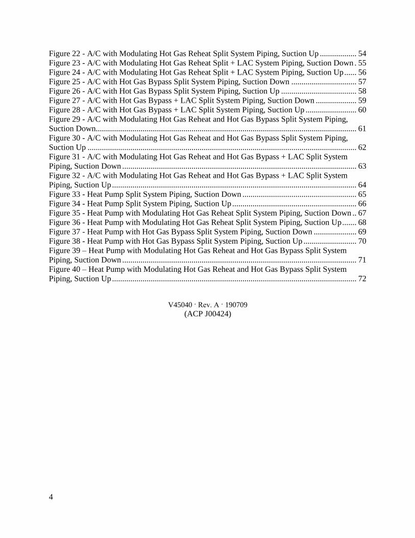
4
Figure 22 - AC with Modulating Hot Gas Reheat Split System Piping Suction Up 54 Figure 23 - AC with Modulating Hot Gas Reheat Split + LAC System Piping Suction Down 55 Figure 24 - AC with Modulating Hot Gas Reheat Split + LAC System Piping Suction Up 56 Figure 25 - AC with Hot Gas Bypass Split System Piping Suction Down 57
Figure 26 - AC with Hot Gas Bypass Split System Piping Suction Up 58 Figure 27 - AC with Hot Gas Bypass + LAC Split System Piping Suction Down 59 Figure 28 - AC with Hot Gas Bypass + LAC Split System Piping Suction Up 60 Figure 29 - AC with Modulating Hot Gas Reheat and Hot Gas Bypass Split System Piping
Suction Down 61
Figure 30 - AC with Modulating Hot Gas Reheat and Hot Gas Bypass Split System Piping
Suction Up 62 Figure 31 - AC with Modulating Hot Gas Reheat and Hot Gas Bypass + LAC Split System
Piping Suction Down 63
Figure 32 - AC with Modulating Hot Gas Reheat and Hot Gas Bypass + LAC Split System
Piping Suction Up 64
Figure 33 - Heat Pump Split System Piping Suction Down 65 Figure 34 - Heat Pump Split System Piping Suction Up 66
Figure 35 - Heat Pump with Modulating Hot Gas Reheat Split System Piping Suction Down 67 Figure 36 - Heat Pump with Modulating Hot Gas Reheat Split System Piping Suction Up 68 Figure 37 - Heat Pump with Hot Gas Bypass Split System Piping Suction Down 69
Figure 38 - Heat Pump with Hot Gas Bypass Split System Piping Suction Up 70 Figure 39 ndash Heat Pump with Modulating Hot Gas Reheat and Hot Gas Bypass Split System
Piping Suction Down 71 Figure 40 ndash Heat Pump with Modulating Hot Gas Reheat and Hot Gas Bypass Split System
Piping Suction Up 72
V45040 Rev A 190709
(ACP J00424)
5
AAON CF Series Features and Options Introduction
Energy Efficiency
bull Two-Stage 10-100 Variable Capacity
or Tandem R-410A Scroll Compressors
bull Air-Source Heat Pump
bull VFD Controlled ECM Driven and
ECM Low Sound Condenser Fans
Humidity Control bull Modulating Hot Gas Reheat
bull Makeup Air Applications up to 100
Outside Air
Safety bull Phase and Brownout Protection
bull Single Point Non-Fused Disconnect
Power Switch
bull Automatic Low Pressure and Manual
Reset High Pressure Safety Cut-outs
bull Adjustable Compressor Lockout
Installation and Maintenance bull Isolated Controls and Compressor
Compartment
bull Access Doors with Full Length Stainless
Steel Piano Hinges
bull Molded Lockable Handles
bull Color-Coded Wiring Diagrams
bull Run Test Report and Installation Manual
Included in Controls Compartment
bull Factory Installed Convenience Outlet
bull Service Access Lights
bull Remote StartStop Terminals
bull Liquid Line Sight Glass
bull Compressor Isolation Valves
System Integration bull Complete Split System with AAON DX
Air Handling Units
bull Remote Air-Cooled Condenser Option
bull Labeled Split System Piping Stub Outs
with Shut-Off Valves
bull Flooded Condenser 0degF Low Ambient
Controls
bull Terminal Block for Thermostat with
Isolation Relays
bull Constant Air Volume (CAV) Makeup
Air (MUA) Variable Air Volume
(VAV) and Single Zone Variable Air
Volume (SZ VAV)
Environmentally Friendly bull R-410A Refrigerant
Extended Life bull Optional 5 Year Compressor Warranty
bull G90 Galvanized Steel Construction
bull 2500 Hour Salt Spray Tested Exterior
Corrosion Protection
bull 10000 Hour Salt Spray Tested Polymer
E-Coated Condenser Coils
bull Copper Fin and Stainless Steel Casing
Coils
bull Condenser Coil Guards
bull Custom Color Paint Options
6
Safety
Attention should be paid to the following statements
NOTE - Notes are intended to clarify the unit installation operation and maintenance
CAUTION - Caution statements are given to prevent actions that may result in equipment
damage property damage or personal injury
WARNING - Warning statements are given to prevent actions that could result in
equipment damage property damage personal injury or death
DANGER - Danger statements are given to prevent actions that will result in equipment
damage property damage severe personal injury or death
QUALIFIED INSTALLER Improper installation adjustment alteration service or maintenance can cause property damage personal injury or loss of life Startup and service must be performed by a Factory Trained Service Technician A copy of this IOM should be kept with the unit
WARNING
ELECTRIC SHOCK Electric shock hazard Before servicing shut off all electrical power to the unit including remote disconnects to avoid shock hazard or injury from rotating parts Follow proper Lockout-Tagout procedures
WARNING
ELECTRIC SHOCK FIRE OR EXPLOSION HAZARD Failure to follow safety warnings exactly could result in dangerous operation serious injury death or property damage Improper servicing could result in dangerous operation serious injury death or property damage When servicing controls label all
wires prior to disconnecting Reconnect wires correctly
Verify proper operation after servicing Secure all doors with key-lock or nut and bolt
WARNING
7
ROTATING COMPONENTS Unit contains fans with moving parts that can cause serious injury Do not remove grill containing fans until the power to the unit has been disconnected and fan has stopped rotating
WARNING
LIVE ELECTRICAL During installation testing servicing and troubleshooting of the equipment it may be necessary to work with live electrical components Only a qualified licensed electrician or individual properly trained in handling live electrical components shall perform these tasks Standard NFPA-70E an OSHA regulation requiring an Arc Flash Boundary to be field established and marked for identification of where appropriate Personal Protective Equipment (PPE) be worn should be followed
WARNING
FIRE EXPLOSION OR CARBON MONOXIDE POISONING HAZARD Failure to replace proper controls could result in fire explosion or carbon monoxide poisoning Failure to follow safety warnings exactly could result in serious injury death or property damage Do not store or use gasoline or other flammable vapors and liquids in the vicinity of this appliance
WARNING
GROUNDING REQUIRED All field installed wiring must be completed by qualified personnel Field installed wiring must comply with NECCEC local and state electrical code requirements Failure to follow code requirements could result in serious injury or death Provide proper unit ground in accordance with these code requirements
WARNING
VARIABLE FREQUENCY DRIVES
Do not leave VFDs unattended in hand mode or manual bypass Damage to personnel or equipment can occur if left unattended When in hand mode or manual bypass mode VFDs will not respond to controls or alarms
WARNING
8
LEAK TESTING
Do not use oxygen acetylene or air in place of refrigerant and dry nitrogen for leak testing A violent explosion may result causing injury or death
WARNING
VARIABLE FREQUENCY DRIVES
Electric motor over-current protection and overload protection may be a function of the Variable Frequency Drive to which the motors are wired Never defeat the VFD motor overload feature The overload ampere setting must not exceed 115 of the electric motors FLA rating as shown on the motor nameplate
CAUTION
PVC PIPING
PVC (Polyvinyl Chloride) and CPVC (Chlorinated Polyvinyl Chloride) are vulnerable to attack by certain chemicals Polyolester (POE) oils used with R-410A and other refrigerants even in trace amounts in a PVC or CPVC piping system will result in stress cracking of the piping and fittings and complete piping system failure
CAUTION
3-PHASE ROTATION
Rotation must be checked on all MOTORS AND COMPRESSORS of 3 phase units at startup by a qualified service technician Scroll compressors are directional and can be damaged if rotated in the wrong direction Compressor rotation must be checked using suction and discharge gauges Fan motor rotation should be checked for proper operation Alterations should only be made at the unit power connection
CAUTION
UNIT HANDLING To prevent injury or death lifting equipment capacity shall exceed unit weight by an adequate safety factor Always test-lift unit not more than 24 inches high to verify proper center of gravity lift point to avoid unit damage injury or death
WARNING
DOOR LATCHES
Door compartments containing hazardous voltage or rotating parts are equipped with door latches that allow locks Door latches are shipped with a nut and bolt requiring tooled access If the shipping hardware is not replaced with a pad lock always re-install the nut and bolt after closing the door to maintain tooled access
CAUTION
9
ENCLOSED AREA
Do not work in an enclosed area where refrigerant or nitrogen gases may be leaking A sufficient quantity of vapors may be present and cause
injury or death
WARNING
COMPRESSOR LUBRICANT
Polyolester (POE) and Polyvinylether (PVE) oils are two types of lubricants used in hydrofluorocarbon (HFC) refrigeration systems Refer to the compressor label for the proper compressor lubricant type
CAUTION
COIL CLEANERS
To prevent damage to the unit do not use acidic chemical coil cleaners Do not use alkaline chemical coil cleaners with a pH value greater than 85 after mixing without first using an aluminum corrosion inhibitor in the cleaning solution
CAUTION
COIL CLEANERS
Some chemical coil cleaning compounds are caustic or toxic Use these substances only in accordance with the manufacturerrsquos usage instructions Failure to follow instructions may result in equipment damage injury or death
WARNING
COIL CLEANING
Do not clean DX refrigerant coils with hot water or steam The use of hot water or steam on refrigerant coils will cause high pressure inside the coil tubing and damage to the coil
CAUTION
CONVENIENCE OUTLETS
Factory installed convenience outlets are not intended for use while the unit is operating
WARNING
10
1 Startup and service must be performed by
a Factory Trained Service Technician
2 The unit is for outdoor use only See
General Information section for more
information
3 Every unit has a unique equipment
nameplate with electrical operational
and unit clearance specifications
Always refer to the unit nameplate for
specific ratings unique to the model
purchased
4 READ THE ENTIRE INSTALLATION
OPERATION AND MAINTENANCE
MANUAL OTHER IMPORTANT
SAFETY PRECAUTIONS ARE
PROVIDED THROUGHOUT THIS
MANUAL
5 Keep this manual and all literature
safeguarded near or on the unit
COMPRESSOR CYCLING
5 MINUTE MINIMUM OFF TIME To prevent motor overheating compressors must cycle off for a minimum of 5 minutes
5 MINUTE MINIMUM ON TIME To maintain the proper oil level compressors must cycle on for a minimum of 5 minutes The cycle rate must not exceed 6 starts per hour
WARNING
CF Series Feature String Nomenclature
Model Options Unit Feature Options G
EN
MJ
RE
V
SIZ
E
SE
RIE
S
MN
RE
V
VL
T
A1
A2
A3
A4
A5
1
2A
2B
3A
3B
4
5
6A
6B
6C
7
8A
8B
8C
8D
9
10
11
12
13
14
15
CF A - 015 - B - A - 3 - D C 0 0 K 0 - A 0 - E 0 - C 0 - A N 0 - B - D E 0 0 - 0 0 A 0 E 0 0
0 0 0 0 0 D B
16
17
18
19
20
21
22
11
CF Series Feature String Nomenclature
MODEL OPTIONS Series and Generation
CF
Major Revision
A
Unit Size
002 = 2 ton Capacity
003 = 3 ton Capacity
004 = 4 ton Capacity
005 = 5 ton Capacity
006 = 6 ton Capacity
007 = 7 ton Capacity
009 = 9 ton Capacity
011 = 11 ton Capacity
013 = 13 ton Capacity
015 = 15 ton Capacity
016 = 16 ton Capacity
018 = 18 ton Capacity
020 = 20 ton Capacity
025 = 25 ton Capacity
026 = 26 ton Capacity
030 = 30 ton Capacity
031 = 31 ton Capacity
040 = 40 ton Capacity
050 = 50 ton Capacity
060 = 60 ton Capacity
070 = 70 ton Capacity
Series
A = 2-7 ton units
B = 9-15 ton units
C = 16-25 amp 30 ton units
D = 26 amp 31-70 ton units
Minor Revision
A
Voltage
1 = 230V1Φ60Hz
2 = 230V3Φ60Hz
3 = 460V3Φ60Hz
4 = 575V3Φ60Hz
8 = 208V3Φ60Hz
9 = 208V1Φ60Hz
A1 Compressor Style
0 = Air-Cooled Condenser - No Compressors
(1 Circuit)
A = R-410A Scroll Compressors
B = R-410A Two Step Capacity Scroll Compressors
D = R-410A Variable Capacity Scroll Compressors
E = R-410A Tandem Scroll Compressors
G = R-410A Tandem Variable Capacity Scroll
Compressors
P = Air-Cooled Condenser - No Compressors
(2 Circuits)
Q = Air-Cooled Condenser - No Compressors
(4 Circuits)
A2 Condenser Style
C = Air-Cooled Condenser
J = Air-Source Heat Pump
A3 Configuration
0 = Standard
A4 Coating
0 = Standard
E = Polymer E-Coated Condenser Coil
G = Copper Fin + Stainless Steel Casing - Condenser
Coil
A5 Staging
0 = No Cooling
G = 1 OnOff Refrigeration System
H = 1 Variable Capacity Refrigeration System
J = 2 OnOff Refrigeration Systems
K = 1 Variable Capacity Refrigeration System + 1
OnOff Refrigeration System
L = 2 Variable Capacity Refrigeration System
R = 4 OnOff Refrigeration Systems
T = 2 Variable Capacity Refrigeration Systems + 2
OnOff Refrigeration Systems
U = 4 Variable Capacity Refrigeration Systems
CF Series Feature String Nomenclature
Model Options Unit Feature Options G
EN
MJR
EV
SIZ
E
SE
RIE
S
MN
RE
V
VL
T
A1
A2
A3
A4
A5
1
2A
2B
3A
3B
4
5
6A
6B
6C
7
8A
8B
8C
8D
9
10
11
12
13
14
15
CF A - 015 - B - A - 3 - D C 0 0 K 0 - A 0 - E 0 - C 0 - A N 0 - B - D E 0 0 - 0 0 A 0 E 0 0
0 0 0 0 0 D B
16
17
18
19
20
21
22
12
UNIT FEATURE OPTIONS 1 Unit Orientation
0 = Vertical Condenser Discharge - Standard Access
A = Horizontal Condenser Discharge - Standard
Access
2A Refrigeration Control
0 = Standard
A = 5 Minute Compressor Off Timer + 20 Second
Compressor Stage Delay
C = Adjustable Fan Cycling
D = Adjustable Compressor Lockout
G = Option A + Adjustable Fan Cycling
H = Option A + Adjustable Compressor Lockout
M = Adjustable Fan Cycling + Adjustable
Compressor Lockout
W = Option A + Adjustable Fan Cycling +
Adjustable Compressor Lockout
2B Blank
0 = Standard
3A Refrigeration Options
0 = Standard
A = Hot Gas Bypass Lead Stage [HGB]
B = HGB Lead + HGB Lag
D = Hot Gas Bypass Non-Variable Capacity
Refrigeration Systems [HGBNV]
E = Modulating Hot Gas Reheat [MHGR]
H = HGB + MHGR
J = HGB Lead + HGB Lag + MHGR
L = HGBNV + MHGR
3B Blank
0 = Standard
4 Refrigeration Accessories
0 = Standard
A = Sight Glass
B = Compressor Isolation Valves
C = Options A + B
D = Flooded Condenser 0degF Low Ambient Controls ndash
One Circuit
E = Options A + D
F = Options B + D
G = Options A + B + D
H = Flooded Condenser 0degF Low Ambient Controls-
Two Circuits
J = Options A + H
K = Options B + H
L = Options A + B + H
R = Flooded Condenser 0degF Low Ambient Controls ndash
Four Circuits
S = Options A + R
T = Options B + R
U = Options A + B + R
5 Blank
0 = Standard
6A Unit Disconnect Type
0 = Single Point Power Block
A = Single Point Power Non-Fused Disconnect
6B Disconnect 1 Size
0 = Standard
N = 100 amps
R = 150 amps
V = 250 amps
Z = 400 amps
6C Blank
0 = Standard
CF Series Feature String Nomenclature
Model Options Unit Feature Options
GE
N
MJR
EV
SIZ
E
SE
RIE
S
MN
RE
V
VL
T
A1
A2
A3
A4
A5
1
2A
2B
3A
3B
4
5
6A
6B
6C
7
8A
8B
8
C
8D
9
10
11
12
13
14
15
CF A - 015 - B - 0 - 3 - D C 0 0 K 0 - A 0 - E 0 - C 0 - A N 0 - B - D C 0 0 - 0 0 A 0 E 0 0 0 0 0 0 0 D B
16
17
18
19
20
21
22
13
7 Accessories
0 = Standard
B = Phase amp Brown Out Protection
D = Suction Pressure Transducer on Each
Refrigeration Circuit
E = Compressor Sound Blanket
L = Options B + D
M = Options B + E
Q = Options D + E
1 = Options B + D + E
8A Control Sequence
A = Terminal Block for Thermostat w Isolation
Relays
D = VAV Unit Controller - VAV Cool + CAV Heat
E = CAV Unit Controller
F = Makeup Air Unit Controller - CAV Cool + CAV
Heat
H = Constant Volume HP Unit Controller - CAV
Cool + CAV Heat
J = Makeup Air HP Unit Controller - CAV Cool +
CAV Heat
N = Field Installed DDC Controls by Others with
Isolation Relays
8B Control Suppliers
0 = Standard
E = Orion VCC-X (Main Controller in Air Handling
Unit)
H = AAON Touchscreen Controller (Main Controller
in Air Handling Unit)
8C Control Supplier Options
0 = Standard
8D BMS Connection amp Diagnostics
0 = Standard
9 Blank
0 = Standard
10 Blank
0 = Standard
11 Maintenance Accessories
0 = Standard
A = Factory Wired 115VAC Convenience Outlet
B = Field Wired 115VAC Convenience Outlet
C = Service Lights
E = Remote Unit StartStop Terminals
F = Options A + C
H = Options A + E
J = Options B + C
L = Options B + E
N = Options C + E
R = Options A + C + E
U = Options B + C + E
12 Code Options
0 = Standard ETL USA Listing
B = ETL USA + Canada Listing
13 Air-Cooled Condenser Accessories
0 = Standard
A = Condenser Coil Guard
C = ECM Condenser Fan Head Pressure Control
E = VFD Condenser Fan Head Pressure Control
G = Options A + C
J = Options A + E
N = ECM Condenser Fan Head Pressure Control +
Low Sound Condenser Fan
S = Options A + N
14 Blank
0 = Standard
15 Blank
0 = Standard
16 Electrical Options
0 = Standard
17 Shipping Options
0 = Standard
A = Crating
B = Export Crating
CF Series Feature String Nomenclature
Model Options Unit Feature Options G
EN
MJR
EV
SIZ
E
SE
RIE
S
MN
RE
V
VL
T
A1
A2
A3
A4
A5
1
2A
2B
3A
3B
4
5
6A
6B
6C
7
8A
8B
8C
8D
9
10
11
12
13
14
15
CF A - 015 - B - A - 3 - D C 0 0 K 0 - A 0 - E 0 - C 0 - A N 0 - B - D E 0 0 - 0 0 A 0 E 0 0
0 0 0 0 0 D B 1
6
17
18
19
20
21
22
14
18 Blank
0 = Standard
19 Blank
0 = Standard
20 Cabinet Material
0 = Galvanized Steel Cabinet
21 Warranty
0 = Standard
D = Compressor Warranty - Years 2-5
22 Type
B = Premium AAON Gray Paint Exterior
E = Premium AAON Gray Paint Ext + Shrink Wrap
X = SPA + Premium AAON Gray Paint Exterior
1 = SPA + Premium AAON Gray Paint Exterior +
Shrink Wrap
15
General Information
AAON CF Series air-cooled condensers and
condensing units have been designed for
outdoor use only They are factory
assembled wired charged and run-tested
Codes and Ordinances
CF Series units have been tested and
certified by ETL in accordance with UL
Safety Standard 1995CSA C222 No 236
System should be sized in accordance with
the American Society of Heating
Refrigeration and Air Conditioning
Engineers Handbook
Installation of CF Series units must conform
to the ICC standards of the International
Mechanical Code the International Building
Code and local building plumbing and
electrical codes All appliances must be
electrically grounded in accordance with
local codes or in the absence of local codes
the current National Electric Code
ANSINFPA 70 or the current Canadian
Electrical Code CSA C221
Receiving Unit
When received the unit should be checked
for damage that might have occurred in
transit If damage is found it should be noted
on the carrierrsquos freight bill A request for
inspection by carrierrsquos agent should be made
in writing at once Nameplate should be
checked to ensure the correct model sizes and
voltages have been received to match the job
requirements
If repairs must be made to damaged goods
then the factory should be notified before any
repair action is taken in order to protect the
warranty Certain equipment alteration
repair and manipulation of equipment
without the manufacturerrsquos consent may void
the product warranty Contact AAON
Technical Support for assistance with
handling damaged goods repairs and freight
claims (918) 382-6450
SHARP EDGES
Coils and sheet metal surfaces present sharp edges and care must be taken when working with equipment
WARNING
QUALIFIED INSTALLER
Improper installation adjustment alteration service or maintenance can cause property damage personal injury or loss of life Installation and service must be performed by a Factory Trained Service Technician
WARNING
Failure to observe the following instructions will result in premature failure of your system and possible voiding of the warranty
WARNING
16
Storage
If installation will not occur immediately
following delivery store equipment in a dry
protected area away from construction traffic
and in the proper orientation as marked on the
packaging with all internal packaging in
place Secure all loose-shipped items
Failure to observe the following instructions
will result in premature failure of your
system and possible voiding of the warranty
Never turn off the main power supply to the
unit except for complete shutdown When
power is cut off from the unit any
compressors using crankcase heaters cannot
prevent refrigerant migration This means the
compressor will cool down and liquid
refrigerant may accumulate in the
compressor The compressor is designed to
pump refrigerant gas and damage may occur
if liquid enters the compressor when power is
restored
Before unit operation the main power switch
must be turned on for at least twenty-four
hours for units with compressor crankcase
heaters This will give the crankcase heater
time to clear any liquid accumulation out of
the compressor before it is required to run
Always control the system from the control
panel never at the main power supply (except
for emergency or for complete shutdown of
the system)
CLEAN AIR ACT
The Clean Air Act of 1990 bans the intentional venting of refrigerant as of July 1 1992 Approved methods of recovery recycling or reclaiming must be followed
CAUTION
CRANKCASE HEATER OPERATION
Units are equipped with compressor crankcase heaters which should be energized at least 24 hours prior to cooling operation to clear any liquid refrigerant from the compressors
CAUTION
3-PHASE ROTATION
Rotation must be checked on all MOTORS AND COMPRESSORS of three phase units All motors to include and not be limited to pump motors and condenser fan motors should all be checked by a qualified service technician at startup and any wiring alteration should only be made at the unit power connection
CAUTION
17
The standard compressors must be on a
minimum of 5 minutes and off for a minimum
of 5 minutes The cycle rate must be no more
than 6 starts per hour
The variable capacity compressors must be
on a minimum of 3 minutes and off for a
minimum of 3 minutes The cycle rate must
be no more than 6 starts per hour
The compressor life will be seriously
shortened by reduced lubrication and the
pumping of excessive amounts of liquid oil
and liquid refrigerant
Wiring Diagrams
A complete set of unit specific wiring
diagram in point-to-point form is laminated
in plastic and located inside the control
compartment door
General Maintenance
When the initial startup is made and on a
periodic schedule during operation it is
necessary to perform routine service checks
on the performance of the condensing unit
This includes reading and recording suction
pressures and checking for normal sub-
cooling and superheat
COMPRESSOR ROTATION
Scroll compressors are directional and will be damaged by operation in the wrong direction Low pressure switches on compressors have been disconnected after factory testing Rotation should be checked by a qualified service technician at startup using suction and discharge pressure gauges and any wiring alteration should only be made at the unit power connection
COMPRESSOR CYCLING
5 MINUTE MINIMUM OFF TIME To prevent motor overheating compressors must cycle off for a minimum of 5 minutes
5 MINUTE MINIMUM ON TIME To maintain the proper oil level compressors must cycle on for a minimum of 5 minutes The cycle rate must not exceed 6 starts per hour
WARNING
CAUTION
18
Installation
Forklifting the Unit
CF Series condensing unit sizes 2-25 amp 30
tons can be lifted using a forklift 2-7 ton
units must have forks at least 48rdquo in length
9-25 amp 30 ton units must have forks 72rdquo in
length or the forks must have 72rdquo fork
extensions Standard units can be lifted from
all sides except the condenser coil side CF
Series condensing unit sizes 26 amp 31-70 tons
cannot be lifted using a forklift They can be
lifted as shown in Figure 3
Forks must be perpendicular to the unit and
they must be in far enough that the back of
the forks are no more than 6rdquo away from the
edge of the unit
Figure 1 - Forklifting a CF Series A Cabinet
Figure 2 - Forklifting a CF Series B and C
Cabinet
FORKLIFTING 2-7 TON UNITS
Forks or Fork Extensions must be at least 48rdquo in length
CAUTION
FORKLIFTING 9-25 amp 30 TON UNITS
Forks or Fork Extensions must be at least 72rdquo in length
CAUTION
19
Lifting the Unit
If cables or chains are used to hoist the unit
they must be the same length Minimum
cable length is 99rdquo for CF Series 9-70 ton
units CF Series 2-7 ton units do not include
factory installed lifting lugs and should be
lifted by forklift only Care should be taken
to prevent damage to the cabinet coils and
condenser fans
Before lifting unit be sure that all shipping
material has been removed from unit Secure
hooks and cables at all lifting points lugs
provided on the unit
Figure 3 ndash Lifting Details and Orientation of
a CF Series 9-70 ton Condensing Unit
Locating the Unit
The CF Series condenser and condensing unit
is designed for outdoor applications and
mounting at ground level or on a rooftop It
must be placed on a level and solid
foundation that has been prepared to support
its weight When installed at ground level a
one-piece concrete slab should be used with
footings that extend below the frost line Also
with ground level installation care must be
taken to protect the coil fins from damage due
to vandalism or other causes
The first clearance table below gives the
clearance values for proper unit operation
The second clearance table gives the
clearance necessary for removing the coil
without disassembling a large part of the
condensing unit For ease of removing the
condenser coil use the second table
clearances for the right hand side of the unit
Table 1 ndashClearances for Proper Operation
Location Unit Size
2-7 tons 9-70 tons
Front -
(Controls
Side)
Unobstructed 36rdquo
Left Side 6rdquo 30rdquo
Right Side 6rdquo 36rdquo
Top 3rdquo Unobstructed
Back 18rdquo 6rdquo
Table 2 ndash Clearances for Coil Pull
Unit Size Right Hand Side
2-7 tons 42rdquo
9-15 tons 42rdquo
16-25 amp 30 tons 54rdquo
26 amp 31-70 tons 66rdquo
Figure 4 - Orientation of Series 2-7 ton
Condensing Unit
20
The placement relative to the building air
intakes and other structures must be carefully
selected Airflow to and from the condenser
or condensing unit must not be restricted to
prevent a decrease in performance and
efficiency
The installation position for 9-70 ton units
must provide at least 30rdquo of left and right side
clearance for proper airflow to the condenser
coils When units are mounted adjacent to
each other the minimum right and left side
clearance required between the units is 60rdquo or
5 feet Similarly when 2-7 ton units are
mounted adjacent to each other the minimum
clearance required between the back side of
the units is 36rdquo or 3 feet
Units should not be installed in an enclosure
or pit that is deeper than the height of the unit
When recessed installation is necessary the
clearance to maintain proper airflow is at
least 5 feet (3 feet for 2-7tons)
CF Series condensers and condensing units
that have a vertical air discharge must have
no obstruction above the equipment Do not
place the unit under an overhang CF Series
condensers and condensing units that have a
horizontal discharge must have no
obstruction in front of the unit
For proper unit operation the immediate area
around condenser must remain free of debris
that may be drawn in and obstruct airflow in
the condensing section
Consideration must be given to obstruction
caused by snow accumulation when placing
the unit
Mounting Isolation
For roof mounted applications or anytime
vibration transmission is a factor vibration
isolators may be used
Access Doors
Access doors are provided to the compressor
and electrical compartment
Standard Evacuation Instructions
Proper system evacuation is critical to
remove moisture and non-condensables from
the system before charging the system with
refrigerant A newly installed AAON
condensing unit has already been evacuated
and charged with some refrigerant at the
factory When evacuating a new system
keep the condensing unit service valves
closed and evacuate the suction and liquid
lines and the air handling unit If the entire
system must be evacuated use the following
procedure to ensure the entire system is
pulled into a good vacuum
1 System evacuation should be
performed anytime a system is open to
atmospheric pressure The POE oils
used with R-410A are extremely
hydroscopic in nature and immediately
begin pulling in moisture once the
system is opened to the atmosphere
2 Before starting to evacuate the
system you MUST ensure that there are
no leaks by pressurizing the system with
PVC PIPING
PVC (Polyvinyl Chloride) and CPVC (Chlorinated Polyvinyl Chloride) are vulnerable to attack by certain chemicals Polyolester (POE) oils used with R-410A and other refrigerants even in trace amounts in a PVC or CPVC piping system will result in stress cracking of the piping and fittings and complete piping system failure
CAUTION
21
400 psig of dry nitrogen and verifying no
pressure loss after one hour
3 Four valve manifold gauge sets are
more effective than standard manifold
gauge sets due to the extra hose port in
combination with a 38rsquorsquo evacuation
port The larger diameter evacuation port
will expedite system evacuation
4 The manifold set should be connected
to the condensing unit with one hose on
the suction line service valve one hose
on the liquid line service valve and if an
extra Schrader valve is field installed on
the suction line connect a third hose (not
shown) The vacuum pump should be
connected to the manifold set using a
38rdquo vacuum rated hose Figure 5 shows
two circuits Both circuits must be
evacuated separately
Figure 5 ndash CU evacuation connections
5 An accurate micron gauge must be
used and checked by pulling a vacuum
on the gauge by itself and verify a rapid
drop to less than 100 microns within a
few minutes
6 The micron gauge should not be
attached to the system until the gauge
manifold is reading 28rsquorsquo of vacuum to
ensure the micron gauge does not see
pressure and is thus damaged MICRON
GAUGES WILL BE DAMAGED BY
PRESSURE
7 It is a good practice to replace the
vacuum pump oil after one hour of the
evacuation process The oil can be
broken down in the pump in the initial
first hour causing system evacuation to
take longer than it should
8 The minimum micron level required
by AAON is 350 microns for systems
using POE oils
9 The system should then be isolated
and the pump turned off to check for
vacuum rise due to leaks or moisture in
the system The micron gauge should
not rise above 500 microns after 30
minutes of wait time
Low Ambient amp Modulating Reheat
System Evacuation Instructions
Proper system evacuation is critical to
remove moisture and non-condensables from
the system before charging the system with
refrigerant Systems with low ambient
flooded condenser option require the
following procedure to ensure the entire
system is pulled into a good vacuum
1 System evacuation should be
performed anytime a system is open to
atmospheric pressure The POE oils
used with R-410A are extremely
hydroscopic in nature and immediately
begin pulling in moisture once the
system is opened to the atmosphere
2 Open the reheat valve to 50 when
evacuating
3 Before starting to evacuate the
system you MUST ensure that there are
no leaks by pressurizing the system with
22
400 psig of dry nitrogen and verifying no
pressure loss after one hour
4 Four valve manifold gauge sets are
more effective than standard manifold
gauge sets due to the extra hose port in
combination with a 38rsquorsquo evacuation
port The larger diameter evacuation port
will expedite system evacuation
5 The manifold set should be connected
to the condensing unit with one hose on
the suction line service valve one hose
on the liquid line service valve and a
third hose on the reheat line service
valve The vacuum pump should be
connected to the manifold set using a
38rdquo vacuum rated hose Figure 6 shows
two circuits The first circuit has a
reheat line the second circuit is just the
suction and liquid line Both circuits
must be evacuated separately
Figure 6 ndash CU evacuation connections
6 FAILURE to connect to the liquid
line service valve will result in the
receiver tank not being fully evacuated
and most likely lead to non-
condensables in the system
7 An accurate micron gauge must be
used and checked by pulling a vacuum
on the gauge by itself and verify a rapid
drop to less than 100 microns within a
few minutes
8 The micron gauge should not be
attached to the system until the gauge
manifold is reading 28rsquorsquo of vacuum to
ensure the micron gauge does not see
pressure and is thus damaged MICRON
GAUGES WILL BE DAMAGED BY
PRESSURE
9 It is a good practice to replace the
vacuum pump oil after one hour of the
evacuation process The oil can be
broken down in the pump in the initial
first hour causing system evacuation to
take longer than it should
10 The minimum micron level required
by AAON is 350 microns for systems
using POE oils
11 The system should then be isolated
and the pump turned off to check for
vacuum rise due to leaks or moisture in
the system The micron gauge should
not rise above 500 microns after 30
minutes of wait time
Adjusting Refrigerant Charge
All AAON CF Series condensers and
condensing units are shipped with a factory
holding charge The factory charge is
different depending on the unit size and
system (heat pump modulating hot gas
reheat LAC) The factory charge per circuit
is shown on the unit nameplate Adjusting the
charge of the system will be required during
installation
23
Adjusting the charge of a system in the field
must be based on determination of liquid sub-
cooling and evaporator superheat On a
system with a thermostatic expansion valve
liquid sub-cooling is more representative of
the charge than evaporator superheat but both
measurements must be taken
Before Charging
Refer to the Unit Nameplate to determine
which refrigerant must be used to charge the
system
Unit being charged must be at or near full
load conditions before adjusting the charge
Units equipped with hot gas bypass must
have the hot gas bypass valve closed to get
the proper charge
Units equipped with hot gas reheat must be
charged with the hot gas valve closed while
the unit is in cooling mode After charging
unit should be operated in reheat
(dehumidification) mode to check for correct
operation
Units equipped with heat pump options
should be charged in cooling mode to get the
proper charge After charging unit should be
operated in heating mode to check for correct
charge Charge may need to be adjusted for
heating mode If adjustments are made in the
heating mode cooling mode must be rerun to
verify proper operation
After adding or removing charge the system
must be allowed to stabilize typically 10-15
minutes before making any other
adjustments
The type of unit and options determine the
ranges for liquid sub-cooling and evaporator
superheat Refer to Table 3 when determining
the proper sub-cooling
For units equipped with low ambient (0degF)
option see the special charging instructions at
the end of this section
Checking Liquid Sub-cooling
Measure the temperature of the liquid line as
it leaves the condenser coil
Read the gauge pressure at the liquid line
close to the point where the temperature was
taken You must use liquid line pressure as it
will vary from discharge pressure due to
condenser coil pressure drop
Convert the pressure obtained to a saturated
temperature using the appropriate refrigerant
temperature-pressure chart
COMPRESSOR LUBRICANT
Polyolester (POE) and Polyvinylether (PVE) oils are two types of lubricants used in hydrofluorocarbon (HFC) refrigeration systems Refer to the compressor label for the proper compressor lubricant type
CAUTION
CLEAN AIR ACT
The Clean Air Act of 1990 bans the intentional venting of refrigerant (CFCrsquos and HCFCrsquos) as of July 1 1992 Approved methods of recovery recycling or reclaiming must be followed Fines andor incarceration may be levied for non-compliance
CAUTION
24
Subtract the measured liquid line temperature
from the saturated temperature to determine
the liquid sub-cooling
Compare calculated sub-cooling to Table 3
for the appropriate unit type and options
Table 3 - Acceptable Refrigeration Circuit
Values
Cooling
Mode
Liquid Sub-
Cooling
Values
Cooling Only Unit4 8-15degF
Cooling Only Unit with Hot
Gas Reheat14 5-15degF
Heat PumpUnit24 2-4degF
Heat Pump Unit with Hot
Gas Reheat34 2-6degF
Cooling Only Unit with
LAC4 8-15degF
Cooling Only Unit with Hot
Gas Reheat amp LAC4 8-15degF
Notes 1 Must be charged with the hot gas valve
closed After charging unit should be
operated in reheat (dehumidification) mode
to check for correct operation
2 The sub-cooling value in this table is for the
unit running in cooling mode of operation
After charging unit should be operated in
heating mode to check for correct operation
3 The sub-cooling value in this table is for the
unit running in cooling mode of operation
and the hot gas valve closed After charging
unit should be operated in reheat
(dehumidification) mode to check for correct
operation and then in heating mode to check
for correct operation
4 Sub-cooling must be increased by 1degF per 10
feet of vertical liquid line rise for R-410A
(AHU above CU) For example a cooling
only unit with hot gas reheat and a vertical
liquid drop can charge to a sub-cooling value
of 5-15degF but a cooling only unit with hot
gas reheat and a vertical liquid rise of 30 ft
must charge to a sub-cooling value of at least
8-15degF DO NOT OVERCHARGE
Refrigerant overcharging leads to excess
refrigerant in the condenser coils resulting in
elevated compressor discharge pressure
Checking Evaporator Superheat
Measure the temperature of the suction line
close to the compressor
Read gauge pressure at the suction line close
to the compressor
Convert the pressure obtained to a saturated
temperature using the appropriate refrigerant
temperature-pressure chart
Subtract the saturated temperature from the
measured suction line temperature to
determine the evaporator superheat
For refrigeration systems with tandem
compressors it is critical that the suction
superheat setpoint on the TXV is set with one
compressor running The suction superheat
should be 10-13degF with one compressor
running The suction superheat will increase
with both compressors in a tandem running
Inadequate suction superheat can allow liquid
refrigerant to return to the compressors which
will wash the oil out of the compressor Lack
of oil lubrication will destroy a compressor
Liquid sub-cooling should be measured with
both compressors in a refrigeration system
running
Compare calculated superheat to the
acceptable cooling mode superheat values of
8-15degF for all system types Superheat will
increase with long suction line runs
25
Adjusting Sub-cooling and Superheat
Temperatures
The system is overcharged if the sub-cooling
temperature is too high compared to Table 3
and the evaporator is fully loaded (low loads
on the evaporator result in increased sub-
cooling) and the evaporator superheat is
within the temperature range of 8-15degF (high
superheat results in increased sub-cooling)
Correct an overcharged system by reducing
the amount of refrigerant in the system to
lower the sub-cooling
The system is undercharged if the superheat
is too high and the sub-cooling is too low
Correct an undercharged system by adding
refrigerant to the system to reduce superheat
and raise sub-cooling
If the sub-cooling is correct and the superheat
is too high the TXV may need adjustment to
correct the superheat
DO NOT OVERCHARGE Refrigerant overcharging leads to excess refrigerant in the condenser coils resulting in elevated compressor discharge pressure
CAUTION
EXPANSION VALVE ADJUSTMENT
Thermal expansion valves must be adjusted to approximately 8-15degF of suction superheat Failure to have sufficient superheat will damage the compressor and void the warranty
CAUTION
26
Special Low Ambient Option Charging
Instructions
For units equipped with low ambient
refrigerant flood back option being charged
in the summer when the ambient
temperature is warm
If the ambient is above 70degF charge to
approximately 1-2degF of sub-cooling
measured at the inlet to the expansion valve
Once enough charge has been added to get
the evaporator superheat and sub-cooling
values to the correct setting more charge
must be added Use Table 4 to find the
additional charge amount required for the
system when running in cold ambient
conditions
Table 4 ndash Charge to Flood Condenser Coil
for Ambient Above 70degF
CF Size of
circuits
Per Circuit
Charge (lbs)
CF 2 3 1 49
CF 4 5 6 7 1 92
CF 9 11 2 91
CF 13 15 2 121
CF 16 18 2 131
CF 20 25 30 2 175
CF 26 31 40 2 180
4 91
CF 50 60 70 2 438
4 221
For units equipped with low ambient
refrigerant flood back option being charged
in the winter when the ambient
temperature is cold
1 If the ambient is below 70degF charge
to approximately 1-2degF of sub-cooling
measured at the inlet to the expansion
valve Once enough charge has been
added to get the evaporator superheat
and sub-cooling values to the correct
setting more charge may need to be
added If the ambient temperature is 0degF
no more charge is required Ambient
temperatures above 0degF will require a
percentage of the per circuit charge
values from Table 4 Using your
ambient temperature find the
percentage value from Table 5 and
multiply the Per Circuit Charge value
from Table 4 and the value to
determine the additional charge amount
Table 5 ndash Charge to Flood Condenser
Coil for Ambient Below 70degF
Condenser
Ambient
Temperature ˚F
Percentage
Per Circuit
Charge from
Table 4
60 60
50 37
40 24
30 15
20 8
0 0
2 The unit should be checked for proper
operation once the ambient temperature
is above 80degF
Example A CF size 31 with tandem
compressors where the ambient
temperature is 40degF
From Table 4 ndash 18 lbs refrigerant charge
per circuit (tandem compressors would
have 2 circuits in this size of CF)
From Table 5 ndash 24 of Table 4 charge
Additional charge needed for a unit with
low ambient flooded condenser controls
= 18 lbs 024 = 432 lbs additional
refrigerant charge per circuit
27
Low Ambient Operation
During low ambient temperatures the vapor
refrigerant will migrate to the cold part of the
system and condense into liquid All CF
Series compressors are provided with factory
installed crankcase heaters to help prevent
liquid refrigerant from slugging the
compressors during startup in low ambient
conditions The condenser or condensing unit
must have continuous power 24 hours prior
to startup This ensures the compressor will
receive sufficient refrigerant vapor at startup
Standard units can operate down to 55degF
ambient temperature
AAON condenser fan head pressure control
units can operate down to 35degF ambient
temperature Three different condenser fan
head pressure control options available are
adjustable fan cycling ECM condenser fan
or VFD controlled condenser fans See
detailed information following
The AAON low ambient (condenser flood-
back) system is used to operate a refrigerant
system down to 0degF outside air temperature
See detailed information following
Fan Cycling Low Ambient
Adjustable fan cycling is a low ambient head
pressure control option that cycles the
condenser fans to maintain refrigerant circuit
head pressures at acceptable levels during
cooling operation The head pressure set
point (100-470 psi) and pressure differential
(35-200 psi) can be field adjusted using a
flathead screwdriver For example if the
head pressure is set to 300psi and the
differential is set to 100psi then fans will cut
in at 300psi and cut out at 200psi Fan
cycling and variable speed condenser fan
head pressure control options allow
mechanical cooling with ambient
temperatures down to 35degF
Figure 7 - Adjustable Fan Cycling Switch
Variable Speed Low Ambient
Variable speed condenser fan head pressure
control is a low ambient head pressure
control option that sends a variable signal in
relation to the refrigerant circuit head
pressure of the system to an electronically
commutated motor (ECM) or VFD The
motor either speeds up or slows down air
flow accordingly in order to maintain
constant head pressure Fan cycling and
variable speed condenser fan head pressure
control options allow mechanical cooling
with ambient temperatures down to 35degF
Flooded Condenser Low Ambient
Flooded condenser low ambient control
maintains normal head pressure during
periods of low ambient When the ambient
temperature drops the condensing
temperature and therefore pressure drops
Without ambient control the system would
shut down on low discharge pressure The
flooded condenser method of low ambient
control fills the condenser coil with liquid
refrigerant decreasing the heat transfer
capacity of the coil which allows the coil to
operate at an acceptable discharge pressure
28
The condenser coil will not be flooded during
summer ambient temperatures so a receiver
is included to store the additional liquid
refrigerant required to flood the condenser
coil in low ambient The receiver is factory-
sized to contain all of the flooded volume
Without a receiver there would be high head
pressures during higher ambient conditions
The low ambient system maintains normal
head pressure during periods of low ambient
by restricting liquid flow from the condenser
to the receiver and at the same time
bypassing hot gas around the condenser to the
inlet of the receiver This reduces liquid
refrigerant flow from the condenser reducing
its effective surface area which in turn
increases the condensing pressure At the
same time the bypassed hot gas raises liquid
pressure in the receiver allowing the system
to operate properly CF Series condensers
and condensing units use an LAC valve for
low ambient operation
LAC Valve
The Low Ambient Control (LAC) valve is a
non-adjustable three way valve that
modulates to maintain receiver pressure As
the receiver pressure drops below the valve
setting (295 psig for R-410A) the valve
modulates to bypass discharge gas around the
condenser The discharge gas warms the
liquid in the receiver and raises the pressure
to the valve setting The following schematic
shows an example system using the LAC
valve
Figure 8 ndash LAC Piping Example
29
Refrigerant Piping
(See back of the manual for refrigerant piping
diagrams)
General
Piping from the condensing unit to the air
handler is the responsibility of the installing
contractor
Use only clean type ldquoACRrdquo copper tubing
that has been joined with high temperature
brazing alloy
The pipe or line sizes must be selected to
meet the actual installation conditions and
NOT simply based on the connection sizes at
the condensing unit or air handler
All CF Series condensing units are provided
with in-line shutoff valves on both the liquid
and suction lines These should remain closed
until the system is ready for start-up after
installation
Piping should conform to generally accepted
practices and codes
Care must be taken not to cross the circuits
on multiple circuit systems
Upon completion of piping connection the
interconnecting piping and air handler MUST
BE evacuated to 500 microns or less leak
checked and charged with refrigerant
Determining Refrigerant Line Size
The piping between the condenser and low
side must ensure
1 Minimum pressure drop and
2 Continuous oil return and
3 Prevention of liquid refrigerant slugging
or carryover
Minimizing the refrigerant line size is
favorable from an economic perspective
reducing installation costs and reducing the
potential for leakage However as pipe
diameters decrease pressure drop increases
Excessive suction line pressure drop causes
loss of compressor capacity and increased
power usage resulting in reduced system
efficiency Excessive pressure drops in the
liquid line can cause the liquid refrigerant to
flash resulting in faulty TXV operation and
improper system performance In order to
operate efficiently and cost effectively while
avoiding malfunction refrigeration systems
must be designed to minimize both cost and
pressure loss
REFRIGERANT PIPING
Line sizes must be selected to meet actual installation conditions not simply based on the connection sizes at the condensing unit or air handling unit
CAUTION
REFRIGERANT PIPING
This section is for information only and is not intended to provide all details required by the designer or installer of the refrigerant piping between the condenser or condensing unit and the air handling unit AAON Inc is not responsible for interconnecting refrigerant piping Consult ASHRAE Handbook ndash Refrigeration and ASME Standards
CAUTION
30
Equivalent Line Length
All line lengths discussed in this manual
unless specifically stated otherwise are
Equivalent Line Lengths The frictional
pressure drop through valves fittings and
accessories is determined by establishing the
equivalent length of straight pipe of the same
diameter Always use equivalent line
lengths when calculating pressure drop
Special piping provisions must be taken
when lines are up vertical risers or in
excessively long line runs AAON does not
recommend running underground
refrigerant lines
Liquid Line
When sizing the liquid line it is important to
minimize the refrigerant charge to reduce
installation costs and improve system
reliability This can be achieved by
minimizing the liquid line diameter
However reducing the pipe diameter will
increase the velocity of the liquid refrigerant
which increases the frictional pressure drop
in the liquid line and causes other
undesirable effects such as noise
Maintaining the pressure in the liquid line is
critical to ensuring sufficient saturation
temperature avoiding flashing upstream of
the TXV and maintaining system efficiency
Pressure losses through the liquid line due to
frictional contact installed accessories and
vertical risers are inevitable Maintaining
adequate sub-cooling at the condenser to
overcome these losses is the only method to
ensure that liquid refrigerant reaches the
TXV
Liquid refrigerant traveling upwards in a riser
loses head pressure If the evaporator is
below the condenser with the liquid line
flowing down the gravitational force will
increase the pressure of the liquid refrigerant
This will allow the refrigerant to withstand
greater frictional losses without the
occurrence of flashing prior to the TXV
A moisture-indicating sight glass may be
field installed in the liquid line to indicate the
occurrence of premature flashing or moisture
in the line The sight glass should not be used
to determine if the system is properly
charged Use temperature and pressure
measurements to determine liquid sub-
cooling not the sight glass
Liquid Line Routing
Care should be taken with vertical risers
When the system is shut down gravity will
pull liquid down the vertical column and
back to the condenser when it is below the
evaporator This could potentially result in
compressor flooding A check valve can be
installed in the liquid line where the liquid
column rises above the condenser to prevent
this The liquid line is typically pitched along
with the suction line or hot gas line to
minimize the complexity of the
configuration
Liquid Line Insulation
In cooling only systems when the liquid line
is routed through regions where temperature
losses are expected no insulation is required
as this may provide additional sub-cooling to
the refrigerant When routing the liquid line
through high temperature areas insulation of
the line is appropriate to avoid loss of sub-
cooling through heat gain
In heat pump systems when the liquid line is
routed through regions where temperature
losses are expected (all lines exposed to
outside air conditions) insulate with a
minimum 1 inch thick Armaflex insulation
as this will prevent capacity loss during
heating mode of operation
31
Liquid Line Guidelines
In order to ensure liquid at the TXV the sum
of frictional losses and pressure loss due to
vertical rise must not exceed available sub-
cooling A commonly used guideline to
consider is a system design with pressure
losses due to friction through the line not to
exceed a corresponding 1-2degF change in
saturation temperature An additional
recommendation is that the sum of frictional
losses (including valve losses filter drier
losses other accessories and line losses) and
pressure loss due to vertical rise should not
exceed 8degF if the available sub-cooling is
10degF
If the velocity of refrigerant in the liquid line
is too great it could cause excessive noise or
piping erosion The recommended maximum
velocities for liquid lines are 100 fpm from
the condenser to a receiver to discourage
fluid backup and 500 fpm from receiver tank
to the evaporator (300 fpm if the line includes
an electric valve to minimize valve induced
liquid hammer)
Liquid Line Accessories
Liquid line shut off valves and filter driers are
factory provided The total length equivalent
of pressure losses through valves elbows and
fittings must be considered when adding
additional components in the field It is a
good practice to utilize the fewest elbows that
will allow the mating units to be successfully
joined
A liquid line receiver is factory installed on
units with modulating hot gas reheat units
with low ambient control flooded condenser
and units with heat pump
Suction Line
The suction line is more critical than the
liquid line from a design and construction
standpoint More care must be taken to
ensure that adequate velocity is achieved to
return oil to the compressor at minimum
loading conditions However reducing the
piping diameter to increase the velocity at
minimal load can result in excessive pressure
losses capacity reduction and noise at full
load
Suction Line Routing
For cooling only systems pitch the suction
line in the direction of flow (about 1 inch per
20 feet of length) to maintain oil flow
towards the compressor and keep it from
flooding back into the evaporator
For heat pump systems do not pitch lines
since they will be flowing in one direction in
cooling mode and the opposite direction in
heating mode
Crankcase heaters are provided to keep any
condensed refrigerant that collects in the
compressor from causing damage or wear
Make sure to provide support to maintain
suction line positioning and insulate
completely between the evaporator and
condensing unit
It is important to consider part load operation
when sizing suction lines At minimum
capacity refrigerant velocity may not be
adequate to return oil up the vertical riser
Decreasing the diameter of the vertical riser
will increase the velocity but also the
frictional loss
For difficult line routing applications a
double suction riser can be applied to the
situation of part load operation with a suction
riser A double suction riser is designed to
return oil at minimum load while not
incurring excessive frictional losses at full
load A double suction riser consists of a
small diameter riser in parallel with a larger
diameter riser and a trap at the base of the
large riser At minimum capacity refrigerant
velocity is not sufficient to carry oil up both
32
risers and it collects in the trap effectively
closing off the larger diameter riser and
diverting refrigerant up the small riser where
velocity of the refrigerant is sufficient to
maintain oil flow At full load the mass flow
clears the trap of oil and refrigerant is carried
through both risers The smaller diameter
pipe should be sized to return oil at minimum
load while the larger diameter pipe should be
sized so that flow through both pipes
provides acceptable pressure drop at full
load
Figure 9 - Double Suction Riser
Construction
A double riser can also be used for heat pump
operation The specific volume (ft3lb) of
refrigerant at the discharge temperature and
pressure (heating mode line conditions) is
significantly lower than the specific volume
at the suction temperature and pressure
(cooling mode line conditions) To
compound the issue the capacity in heating
mode is lower than the capacity in cooling
mode The discharge velocity in the riser
during heating mode is much lower than the
suction velocity during cooling mode Often
a double riser is necessary to get acceptable
velocities for the discharge mode and
acceptable velocities for the suction mode In
the example diagrams (See Figure 10 amp
Figure 11) the cooling mode will use both
lines and the heating mode will use only one
Suction Line Traps
Include a trap immediately after the
evaporator coil outlet to protect the TXV bulb
from liquid refrigerant
Include traps every 20 feet in vertical suction
riser sections for cooling only systems and
every 12 feet for heat pump systems
Suction Line Insulation
The entire suction line should be insulated
with a minimum 1 inch thick Armaflex
insulation This prevents condensation from
forming on the line and reduces any potential
loss in capacity associated with heat gain
placing additional load on the system This
line should still be insulated in heat pump
systems even though it acts as both a
discharge and suction line
Suction Line Guidelines
For proper performance suction line
velocities less than a 4000 fpm maximum are
recommended The minimum velocity
required to return oil is dependent on the pipe
diameter however a general guideline of
1000 fpm minimum may be applied
When suction flow is up variable capacity
compressors require a minimum velocity of
1500 fpm at full load
Tandem compressors must be considered for
full load operation (both compressors
operating) and at partial load (only one
compressor operating) When suction flow is
up and the tandem has a variable capacity
compressor the velocity for only one
compressor in operation must be greater than
1500 fpm For onoff compressors the
velocity must be greater than the minimum
velocity required to return oil
Heat pump vapor lines must be checked for
suction flow (cooling mode operation) and
discharge flow (heating mode operation)
33
The same line must be used for both modes
of operation
In a fashion similar to the liquid line a
common guideline to consider is a system
design with pressure losses due to friction
through the line not to exceed a
corresponding 1-2degF change in saturation
temperature
For split system piping with long horizontal
runs and short vertical risers a smaller pipe
size can be used to provide sufficient velocity
to return oil in vertical risers at part loads and
a larger size pipe can be used on the
horizontal runs and vertical drop sections
This helps with oil return yet keeps the
pressure drop to a minimum
Suction Line Accessories
If the job requirements specify suction
accumulators they must be separately
purchased and field installed Heat pump
units will include a factory installed suction
accumulator
Discharge Line
The discharge line is similar to the suction
line from a design and construction
standpoint Care must be taken to ensure that
adequate velocity is achieved to return oil to
the compressor at minimum loading
conditions However reducing the piping
diameter to increase the velocity at minimal
load can result in excessive pressure losses
capacity reduction and noise at full load
Pressure loss in the discharge line has less of
an impact on capacity than pressure loss in
the suction line Pressure loss in the
discharge line causes the compressors to
work harder and thus use more power
Discharge Line Routing
For cooling only remote condenser systems
pitch the discharge line in the direction of
flow (about 1 inch per 20 feet of length) to
maintain oil flow towards the compressor
In a heat pump system the field installed
suction line is also used as a discharge line in
the heating mode of operation so the line
must be sized to meet both the suction line
conditions in cooling mode and the discharge
line conditions in heating mode
Because it is used in both directions for a heat
pump unit the line should be installed level
not pitched to facilitate oil return in both
modes of operation
It is important to consider part load operation
when sizing discharge lines At minimum
capacity refrigerant velocity may not be
adequate to return oil up the vertical riser
Decreasing the diameter of the vertical riser
will increase the velocity but also the
frictional loss
For difficult line routing applications a
double discharge riser can be applied to the
situation of part load operation with a
discharge riser A double discharge riser is
designed to return oil at minimum load while
not incurring excessive frictional losses at
full load A double discharge riser consists of
a small diameter riser in parallel with a larger
diameter riser and a trap at the base of the
large riser At minimum capacity refrigerant
velocity is not sufficient to carry oil up both
risers and it collects in the trap effectively
closing off the larger diameter riser and
diverting refrigerant up the small riser where
SUCTION RISER TRAPS
Circuits require suction riser traps every 20 feet (every 12 feet for heat pumps)
CAUTION
34
velocity of the refrigerant is sufficient to
maintain oil flow At full load the mass flow
clears the trap of oil and refrigerant is carried
through both risers The smaller diameter
pipe should be sized to return oil at minimum
load while the larger diameter pipe should be
sized so that flow through both pipes
provides acceptable pressure drop at full
load (See the Double Suction Riser
Construction Figure 9)
A double riser can also be used for heat pump
operation The specific volume (ft3lb) of
refrigerant at the discharge temperature and
pressure (heating mode line conditions) is
significantly lower than the specific volume
at the suction temperature and pressure
(cooling mode line conditions) To
compound the issue the capacity in heating
mode is lower than the capacity in cooling
mode The discharge velocity in the riser
during heating mode is much lower than the
suction velocity during cooling mode Often
a double riser is necessary to get acceptable
velocities for the discharge mode and
acceptable velocities for the suction mode In
the example diagrams the cooling mode will
use both lines and the heating mode will use
only one See the following schematics that
illustrate how the double discharge riser can
work for heat pump applications
Figure 10 ndash Heat Pump Piping Schematic of
Cooling Mode in Double Riser
Figure 11 ndash Heat Pump Piping Schematic of
Heating Mode in Double Riser
35
Discharge Line Traps
Include traps every 12 feet in vertical
discharge riser sections
Discharge Line Insulation
Although a typical discharge line does not
need to be insulated the suction line does
Since the same line is used for both the line
must be insulated as described in the Suction
Line Insulation section
Discharge Line Guidelines
For proper performance discharge line
velocities less than a 3500 fpm maximum are
recommended The minimum velocity
required to return oil is dependent on the pipe
diameter however a general guideline of
900 fpm minimum may be applied
When discharge flow is up variable capacity
compressors require a minimum velocity of
900 fpm at full load
Tandem compressors must be considered for
full load operation (both compressors
operating) and at partial load (only one
compressor operating) When discharge flow
is up and the tandem has a variable capacity
compressor the velocity for only one
compressor in operation must be greater than
900 fpm For onoff compressors the
velocity must be greater than the minimum
velocity required to return oil
Heat pump vapor lines must be checked for
suction flow (cooling mode operation) and
discharge flow (heating mode operation)
The same line must be used for both modes
of operation
In a fashion similar to the suction line a
common guideline to consider is a system
design with pressure losses due to friction
through the line not to exceed a
corresponding 1-2degF change in saturation
temperature
For split system piping with long horizontal
runs and short vertical risers a smaller pipe
size can be used to provide sufficient velocity
to return oil in vertical risers at part loads and
a larger size pipe can be used on the
horizontal runs and vertical drop sections
This helps with oil return yet keeps the
pressure drop to a minimum
Hot Gas Bypass Line
Hot Gas Bypass is available for use with DX
systems that may experience low suction
pressure during the operating cycle This may
be due to varying load conditions associated
with VAV applications or units supplying a
large percentage of outside air The system is
designed to divert refrigerant from the
compressor discharge to the low pressure
side of the system in order to keep the
evaporator from freezing and to maintain
adequate refrigerant velocity for oil return at
minimum load
Hot discharge gas is redirected to the
evaporator inlet via an auxiliary side
connector (ASC) to false load the evaporator
when reduced suction pressure is sensed
Field piping between the condensing unit
and the evaporator is required
Hot Gas Bypass Piping Considerations
Pitch the hot gas bypass (HGB) line
downward in the direction of refrigerant
flow toward the evaporator
DISCHARGE RISER TRAPS
Circuits require discharge riser traps every 12 feet
CAUTION
36
When installing vertical hot gas bypass lines
an oil drip line must be provided at the lowest
point in the system The oil drip line must be
vertical its diameter should be the same as
the diameter of the riser and it should be
1 foot long Install a sight glass in the oil drip
line for observation Run an oil return line
using 18 inch capillary tube 10 feet in
length from the hot gas bypass line oil drip
line to the suction line Connect the oil return
line below the sight glass and 1 inch above
the bottom of the oil drip line
Figure 12 ndash Oil Return Line
HGB valves are adjustable Factory HGB
valve settings will be sufficient for most
applications but may require slight
adjustments for some applications including
some make up air applications
Insulate the entire length of the HGB line
with a minimum 1 inch thick Armaflex
insulation
Hot Gas Bypass Line Guidelines
Choose a small size line to ensure oil return
and minimize refrigerant charge
Maintain velocities below a maximum of
3500 fpm A general minimum velocity
guideline to use is approximately 2000 fpm
Hot Gas Reheat
The AAON modulating hot gas reheat system
diverts hot discharge gas from the condenser
to the air handling unit through the hot gas
line Field piping between the condensing
unit and the air handler is required
The line delivers the hot discharge gas to the
reheat coil andor the hot gas bypass valve so
it is sized as a discharge line
Discharge lines should be sized to ensure
adequate velocity of refrigerant to ensure oil
return avoid excessive noise associated with
velocities that are too high and to minimize
efficiency losses associated with friction
Pitch the hot gas line in the direction of flow
for oil return
When installing vertical hot gas reheat lines
an oil drip line must be provided at the lowest
point in the system The oil drip line must be
vertical its diameter should be the same as
the diameter of the riser and it should be
1 foot long Run an oil return line using 18
inch capillary tube 10 feet in length from the
hot gas reheat line oil drip line to the suction
line Connect the oil return line below the
sight glass and 1 inch above the bottom of the
oil drip line (See Oil Return Line Figure 12)
Insulate the entire length of the hot gas line
with a minimum 1 inch thick Armaflex
insulation
Hot Gas Reheat Guidelines
Maintain velocities below a maximum of
3500 fpm A general minimum velocity
guideline is 2000 fpm
37
Electrical
The single point electrical power connections
are made in the electrical control compartment
Verify the unit nameplate voltage agrees with
the power supply Connect power and control
field wiring as shown on the unit specific
wiring diagram provided with the unit
Table 6 - Nameplate Voltage Markings
Voltage Feature
Nameplate
Voltage
Marking
MinMax
VAC
1 230V1Φ60Hz 230 197252
2 230V3Φ60Hz 230 197252
3 460V3Φ60Hz 460 456504
4 575V3Φ60Hz 575 570630
8 208V3Φ60Hz 208 197228
9 208V1Φ60Hz 208 197228
NOTE Units are factory wired for 208V
230V 460V or 575V In some units the 208V
and 230V options may also be provided in
single or three phase configurations The
transformer configuration must be checked by
a qualified technician prior to startup
Size supply conductors based on the unit MCA
rating Supply conductors must be rated a
minimum of 167degF (75degC)
Route power and control wiring separately
through the utility entry Do not run power and
signal wires in the same conduit
Protect the branch circuit in accordance with
code requirements The unit must be
electrically grounded in accordance with local
codes or in the absence of local codes the
current National Electric Code ANSINFPA
70 or the current Canadian Electrical Code
CSA C221
Power wiring is to the unit terminal block or
main disconnect All wiring beyond this point
has been done by the manufacturer and cannot
be modified without affecting the units
agencysafety certification
Three phase voltage imbalance will cause
motor overheating and premature failure The
maximum allowable imbalance is 5
Voltage imbalance is defined as 100 times the
maximum deviation from the average voltage
divided by the average voltage
Example
(218V+237V+235V)3 = 230V then
100(230V-218V)230V = 52 which
exceeds the allowable imbalance
Check voltage imbalance at the unit disconnect
switch and at the compressor terminal
Contact your local power company for line
voltage corrections
3-PHASE ROTATION
Rotation must be checked on all MOTORS AND COMPRESSORS of three phase units Condenser fan motors should be checked by a qualified service technician at startup and any wiring alteration should only be made at the unit power connection Variable frequency drives are programmed to automatically rotate the fan in the correct rotation Do not rely on fans with variable frequency drives for compressor rotation
CAUTION
38
NOTE Startup technician must check for
proper motor rotation and check fan motor
amperage listed on the motor nameplate is not
exceeded Motor overload protection may be a
function of the variable frequency drive and
must not be bypassed
Wire control signals to the unitrsquos low voltage
terminal block located in the controls
compartment
If any factory installed wiring must be
replaced use a minimum 221degF (105degC) type
AWM insulated conductors
ELECTRIC SHOCK
Electric shock hazard Before attempting to perform any installation service or maintenance shut off all electrical power to the unit at the disconnect switches Unit may have multiple power supplies Failure to disconnect power could result in dangerous operation serious injury death or property damage
WARNING
SEALING ELECTRICAL ENTRIES
Installing Contractor is responsible for proper sealing of the electrical entries into the unit Failure to seal the entries may result in damage to the unit and property
CAUTION
39
Startup (See back of the manual for startup form)
Before startup of the condenser or condensing
unit make sure that the following items have
been checked
1 Verify that electrical power is available to
the unit
2 Verify that any remote stopstart device
connected to the unit controller is
requesting the unit to start
Cycle through all the compressors to confirm
that all are operating within tolerance
While performing the check use the startup
form to record observations of amps and
refrigerant pressures
When all is running properly place the
controller in the Run mode and observe the
system until it reaches a steady state of
operation
Compressor Operation
The compressors must be off for a minimum of
5 minutes and on for a minimum of 5 minutes
Short cycling of the compressors can cause
undue stress and wear
3-PHASE ROTATION
Rotation must be checked on all MOTORS AND COMPRESSORS of three phase units Condenser fan motors should all be checked by a qualified service technician at startup and any wiring alteration should only be made at the unit power connection Variable frequency drives are programmed to automatically rotate the fan in the correct rotation Do not rely on fans with variable frequency drives for compressor rotation
CAUTION
ELECTRIC SHOCK
Electric shock hazard Shut off all electrical power to the unit to avoid shock hazard or injury from rotating parts
WARNING
QUALIFIED INSTALLER
Improper installation adjustment alteration service or maintenance can cause property damage personal injury or loss of life Startup and service must be performed by a Factory Trained Service Technician
WARNING
Before completing installation a complete operating cycle should be observed to verify that all components are functioning properly
CAUTION
40
Variable Capacity Compressor Controller
Units with variable capacity scroll
compressors may include a variable capacity
compressor controller The following is an
explanation of the terminals and
troubleshooting of the alert flash codes on the
controller For more information on the
compressor controller see Emerson Climate
Bulletin AE8-1328
Figure 13 - Variable Capacity Compressor
Controller
Note When using field controls any variable
capacity compressors should run at 100 for 1
minute when starting
Low Voltage Terminals
24COM Module Common
24VAC Module Power
C1 Demand Input -
C2 Demand Input +
P1 Pressure Common
P2 Pressure Input
P3 Pressure Power 5VDC
P4 Pressure Shield
P5 Pressure Output -
P6 Pressure Output +
T1 amp T2 Discharge Temperature Sensor
High Voltage Terminals
A1 amp A2 Alarm Relay Out
M1 amp M2 Contactor
L1 Control Voltage N
L2 Control Voltage L
U1 amp U2 Variable Capacity Unloader Solenoid
V1 amp V2 Vapor Injection Solenoid
The compressor controller modulates the
compressor unloader solenoid in an onoff
pattern according the capacity demand signal
of the system The following table shows the
linear relationship between the demand signal
and compressor capacity modulation The
compressor controller also protects the
compressor against high discharge
temperature Refer to Table 8 for the
relationship between thermistor temperature
readings and resistance values
COMPRESSOR CONTROLLER
To avoid damaging the compressor controller DO NOT connect wires to terminals C3 C4 T3 T4 T5 or T6
WARNING
COMPRESSOR CYCLING
5 MINUTE MINIMUM OFF TIME To prevent motor overheating compressors must cycle off for a minimum of 5 minutes
5 MINUTE MINIMUM ON TIME To maintain the proper oil level compressors must cycle on for a minimum of 5 minutes The cycle rate must not exceed 6 starts per hour
WARNING
41
Table 7 - Demand Signal vs Compressor Capacity Modulation
Figure 14 - Compressor Controller Flash Code Details
Demand
Signal (VDC) Loaded Unloaded Time Loaded
Time
Unloaded
Compressor
Capacity
100 Off Off Off Off 0
144 10 90 15 sec 135 sec 10
300 50 50 75 sec 75 sec 50
420 80 20 12 sec 3 sec 80
500 100 0 15 sec 0 sec 100
42
Table 8 - Thermistor Temperature vs Resistance Values
degC degF kΩ degC degF kΩ
-40 -40 288960 75 167 1273
-35 -31 208722 80 176 1079
-30 -22 152220 85 185 920
-25 -13 112144 90 194 787
-20 -4 83472 95 203 677
-15 5 62728 100 212 585
-10 14 47574 105 221 509
-5 23 36399 110 230 445
0 32 28082 115 239 387
5 41 21841 120 248 335
10 50 17117 125 257 292
15 59 13514 130 266 258
20 68 10744 135 275 228
25 77 8600 140 284 202
30 86 6928 145 293 180
35 95 5616 150 302 159
40 104 4581 155 311 139
45 113 3758 160 320 125
50 122 3099 165 329 112
55 131 2568 170 338 101
60 140 2140 175 347 092
65 149 1791 180 356 083
70 158 1507
Compressor Lockouts
Some units include adjustable compressor
lockouts The compressor lockout in the
picture below can be set to any temperature
between -10degF and 70degF The ambient
temperature sensor hangs right outside the
unit with a cover
Figure 15 - Adjustable compressor lockout
Heat pump units include a non-adjustable
compressor lockout for the cooling mode set
to 55degF and an adjustable compressor
lockout for the heating mode that can be set
between 20degF to 95degF If a heat pump is
selected with the compressor lockout feature
the adjustable compressor lockout will
change to the -10degF to 70degF range
Figure 16 - Ambient sensor cover
43
Maintenance
General
Qualified technicians must perform routine
service checks and maintenance This
includes reading and recording the
condensing and suction pressures and
checking for normal sub-cooling and
superheat
Compressors
The scroll compressors are fully hermetic and
require no maintenance except keeping the
shell clean
Refrigerant Filter Driers
Each refrigerant circuit contains a filter drier
Replacement is recommended when there is
excessive pressure drop across the assembly
or moisture is indicated in a liquid line sight
glass
Table 9 - Max Filter Drier Pressure Drops
Circuit Loading Max Pressure Drop
100 10 psig
50 5 psig
Oil Level
It is critical that the refrigerant line piping is
designed to maintain proper oil return to the
compressors Some systems may require oil
to be added in addition to what is provided in
the compressors The oil is a POE type and
is available from your AAON Representative
under part number R63681
Proper oil level should be observed under
minimum load conditions On units equipped
with tandem compressors all oil is returned
to the lead compressor in each tandem pair
When only the lead compressor is running
the oil level should be a minimum of ⅜ from
the bottom of the sight glass With both
compressors running the level in the lead
compressor should drop to the bottom of the
sight glass and the level in the second
compressor should be a minimum of ⅜ from
the bottom of its sight glass Do not allow the
oil level in the sight glass to exceed frac34 full
level
44
Table 10 - R-410A Refrigerant Temperature-Pressure Chart
degF PSIG degF PSIG degF PSIG degF PSIG degF PSIG
20 783 47 1347 74 2137 101 3210 128 4632
21 800 48 1372 75 2171 102 3256 129 4693
22 818 49 1397 76 2206 103 3302 130 4754
23 836 50 1422 77 2241 104 3349 131 4816
24 854 51 1448 78 2277 105 3396 132 4878
25 872 52 1474 79 2313 106 3444 133 4941
26 891 53 1501 80 2349 107 3493 134 5005
27 910 54 1528 81 2386 108 3542 135 5069
28 929 55 1555 82 2423 109 3591 136 5134
29 949 56 1582 83 2460 110 3641 137 5200
30 968 57 1610 84 2498 111 3691 138 5266
31 988 58 1638 85 2537 112 3742 139 5333
32 1009 59 1667 86 2575 113 3794 140 5401
33 1029 60 1696 87 2614 114 3846 141 5470
34 1050 61 1725 88 2654 115 3899 142 5539
35 1071 62 1754 89 2694 116 3952 143 5609
36 1092 63 1784 90 2735 117 4005 144 5679
37 1114 64 1815 91 2776 118 4059 145 5751
38 1136 65 1845 92 2817 119 4114 146 5823
39 1158 66 1876 93 2859 120 4169 147 5896
40 1181 67 1907 94 2901 121 4225 148 5969
41 1203 68 1939 95 2944 122 4282 149 6044
42 1227 69 1971 96 2987 123 4339 150 6119
43 1250 70 2004 97 3030 124 4396
44 1274 71 2036 98 3075 125 4454
45 1298 72 2070 99 3119 126 4513
46 1322 73 2103 100 3164 127 4573
Lubrication
All original motors and bearings are
furnished with an original factory charge of
lubrication Certain applications require
bearings be re-lubricated periodically The
schedule will vary depending on operating
duty temperature variations or severe
atmospheric conditions
Bearings should be re-lubricated at normal
operating temperatures but not when
running
Condenser Tube Inspection
The coils are leak tested at 650 psig before
shipment AAON will not be responsible for
loss of refrigerant It is the responsibility of
the installer to verify that the system is sealed
before charging with refrigerant
Maintenance Recommendations
Fan Motor Maintenance
Cleaning - Remove oil dust water and
chemicals from exterior of motor Keep
motor air inlet and outlet open Blow out
45
interior of open motors with clean
compressed air at low pressure
Labeled Motors - It is imperative for repair of
a motor with Underwritersrsquo Laboratories
label that original clearances be held that all
plugs screws other hardware be fastened
securely and that parts replacements be exact
duplicates or approved equals Violation of
any of the above invalidates Underwritersrsquo
Label
Access Doors
If scale deposits or water is found around the
access doors adjust door for tightness
Adjust as necessary until leaking stops when
door is closed
Propeller Fans and Motors
The fans are directly mounted on the motor
shafts and the assemblies require minimal
maintenance except to assure they are clear
of dirt or debris that would impede the
airflow
Recommended Annual Inspection
In addition to the above maintenance
activities a general inspection of the unit
surface should be completed at least once a
year
Air-Cooled Condenser
The air-cooled condenser section rejects heat
by passing outdoor air over the fin tube coils
for cooling of the hot refrigerant gas from the
compressors
The condenser coils should be inspected
annually to ensure unrestricted airflow If the
installation has a large amount of airborne
dust or other material the condenser coils
should be cleaned with a water spray in a
direction opposite to airflow Care must be
taken to prevent bending of the aluminum
fins on the copper tubes
E-Coated Coil Cleaning
Documented quarterly cleaning of e-coated
coils is required to maintain coating warranty
coverage E-Coated Coil Maintenance
Record document is available on the AAON
website
Surface loaded fibers or dirt should be
removed prior to water rinse to prevent
restriction of airflow If unable to back wash
the side of the coil opposite of the coils
entering air side then surface loaded fibers or
dirt should be removed with a vacuum
cleaner If a vacuum cleaner is not available
a soft non-metallic bristle brush may be used
In either case the tool should be applied in
the direction of the fins Coil surfaces can be
easily damaged (fin edges bent over) if the
tool is applied across the fins
Use of a water stream such as a garden hose
against a surface loaded coil will drive the
fibers dirt and salts into the coil This will
make cleaning efforts more difficult Surface
loaded fibers must be completely removed
prior to using low velocity clean water rinse
Quarterly cleaning is required to maintain
warranty coverage and is essential to
maintain the life of an E-coated coil Coil
cleaning shall be part of the units regularly
scheduled maintenance procedures
ELECTRIC SHOCK
Electric shock hazard Shut off all electrical power to the unit to avoid shock hazard or injury from rotating parts
WARNING
46
Failure to clean an E-coated coil on the
prescribed quarterly cycle will void the
warranty and may result in reduced
efficiency and durability in the environment
A routine two-step quarterly coil cleaning is
required to maintain warranty
Step one is to clean the coil with the below
approved coil cleaner (see approved products
list under the Recommended Coil Cleanersrdquo
section
Step two is to use the approved saltchloride
remover under the Recommended Chloride
Removerrdquo section to dissolve soluble salts
and revitalize the unit It is very important
when cleaning andor rinsing not to exceed
130degF and potable water pressure is less than
100 psig to avoid damaging the unit and coil
fin edges
For routine quarterly cleaning first clean the
coil with the below approved coil
cleaner After cleaning the coils with the
approved cleaning agent use the approved
chloride remover to remove soluble salts and
revitalize the unit
Recommended Coil Cleaner ndash Step 1
GulfCoatTM Coil Cleaner assuming it is
used in accordance with the manufacturers
directions on the container for proper mixing
and cleaning has been approved for use on
E-coated coils to remove mold mildew dust
soot greasy residue lint and other
particulate Never use any cleaners that are
not approved
Recommended Chloride Remover ndash Step 2
CHLORRIDreg Concentrate assuming it
is used in accordance with the manufacturers
directions on the container for proper mixing
has been approved for use on E-coated coils
to remove chloridessalts amp sulfates Never
use any chloride removers that are not
approved
Warranty Protection ndash Step 1
Complete the coil cleaning following these
steps
1 Ensure that the power to the unit is off
and locked out
High velocity water from a pressure washer or compressed air should only be used at a very low pressure to prevent fin andor coil damages The force of the water or air jet may bend the fin edges and increase airside pressure drop Reduced unit performance or nuisance unit shutdowns may occur
Harsh chemicals household bleach or acid cleaners should not be used to clean e-coated coils These cleaners can be very difficult to rinse out of the coil and can accelerate corrosion and attack the e-coating If there is dirt below the surface of the coil use the recommended coil cleaners
CAUTION
CAUTION
47
2 Clean the area around the unit if
needed to ensure leaves grass or
loose debris will not be blown into the
coil
3 Remove panels or tops as required
gaining access to the coil(s) to be
cleaned
4 Using a pump up sprayer fill to the
appropriate level with potable water
and add the correct amount of
approved cleaner as per manufacture
instructions leaving room for the
pump plunger to be reinserted
NOTE Coils should always be cleaned
back flushed opposite of airflow to prevent
impacting the dirt into the coil
5 If the coils have heavy dirt fibers
grass leaves etc on the interior or
exterior face areas a vacuum and
brush should be used to remove those
surface contaminants prior to
applying cleaner The interior floor
drain tray or pan areas should also be
vacuumed
6 Apply the mixed cleaner to coil
surfaces using a pressurized pump up
sprayer maintaining a good rate of
pressure and at a medium size nozzle
spray (not a solid stream and not a
wide fan but somewhere in the
middle) Work in sectionspanels
ensuring that all areas are covered and
kept wetted
7 Apply the cleaner to unit interior air
exiting side coil surfaces first Work
in sectionspanels moving side to side
and from top to bottom
8 Generously soak coils by spraying
cleaner directly on and into the fin
pack section to be cleaned and allow
the cleaning solution to soak for 5 to
10 minutes
9 Using pressurized potable water
(lt100 psi) rinse the coils and
continue to always work in
sectionspanels Start at the top of the
coil and slowly move vertically
downward to the bottom Then
staying in the same vertical area
slowly move back up to the top where
you started Now move over slightly
overlapping the area just completed
and repeat above Continue until all
coil areas on the inside of the unit
have been rinsed
10 Complete steps 5-9 for the exterior air
entering side of the coils
11 Final rinse ndash Now complete a quick
rinse of both sides of the coil
including the headers piping
u-bends and hairpins
12 If the coil has a drain pan or unit floor
that is holding rinse water or cleaner
extra time and attention will need to
be taken in those areas to ensure a
proper rinse has been completed
Warranty Protection ndash Step 2
Complete the coil chloride (salt) removal
following these steps
1 CHLORRIDreg is a concentrate to be
used for both normal inland
applications at a 1001 mix ratio OR
for severe coastal applications 501
mix ratio with potable water
(256 ounces of Chlorrid to 1 gal of
water) Using a pump up sprayer fill
to the appropriate level with potable
water and add the correct amount of
CHLORRIDreg salt remover leaving
room for the pump plunger to be
reinserted
48
2 Apply CHLORRIDreg to all external
coil surfaces using a pressurized
pump up sprayer maintaining a good
rate of pressure and at a medium size
nozzle spray (not a solid stream and
not a wide fan but somewhere in the
middle) Work in sectionspanels
ensuring that all areas are covered and
kept wetted
3 Generously soak coils by spraying
CHLORRIDreg directly on and into
the fin pack section Let stand for 5 to
10 minutes keeping the area wetted
Do not allow to dry before rinsing
4 Using pressurized potable water
(lt100 psi) rinse the CHLORRIDreg
and dissolved chloridessalts off of
the coils continuing to always work in
sectionspanels
5 Starting at the top of the coil begin
rinsing the coil from side to side until
you reach the bottom Repeat as many
times as is necessary to ensure all coil
sectionspanels have been completed
and are thoroughly rinsed
6 Reinstall all panels and tops that were
removed
Service
If the unit will not operate correctly and a
service company is required only a company
with service technicians qualified and
experienced in both refrigerant chillers and
air conditioning are permitted to service the
systems to keep warranties in effect If
assistance is required the service technician
must contact AAON
Warranties
Please refer to the limitation of warranties in
effect at the time of purchase
Replacement Parts
Parts for AAON equipment may be obtained
by contacting your local AAON
representative When ordering parts
reference the serial number and part number
located on the external or internal nameplate
of the unit
AAON Technical Support
203 Gum Springs Rd
Longview TX 75602
Ph (918) 382-6450
techsupportAAONcom
wwwAAONcom
NOTE Before calling technician should
have model and serial number of the unit
available for the customer service department
to help answer questions regarding the unit
49
Split System Refrigerant Piping Diagrams
Figure 17 - AC Split System Piping Suction Down
50
Figure 18 - AC Split System Piping Suction Up
51
Figure 19 - AC with LAC Split System Piping Suction Down
52
Figure 20 - AC with LAC Split System Piping Suction Up
53
Figure 21 - AC with Modulating Hot Gas Reheat Split System Piping Suction Down
54
Figure 22 - AC with Modulating Hot Gas Reheat Split System Piping Suction Up
55
Figure 23 - AC with Modulating Hot Gas Reheat Split + LAC System Piping Suction Down
56
Figure 24 - AC with Modulating Hot Gas Reheat Split + LAC System Piping Suction Up
57
Figure 25 - AC with Hot Gas Bypass Split System Piping Suction Down
58
Figure 26 - AC with Hot Gas Bypass Split System Piping Suction Up
59
Figure 27 - AC with Hot Gas Bypass + LAC Split System Piping Suction Down
60
Figure 28 - AC with Hot Gas Bypass + LAC Split System Piping Suction Up
61
Figure 29 - AC with Modulating Hot Gas Reheat and Hot Gas Bypass Split System Piping
Suction Down
62
Figure 30 - AC with Modulating Hot Gas Reheat and Hot Gas Bypass Split System Piping
Suction Up
63
Figure 31 - AC with Modulating Hot Gas Reheat and Hot Gas Bypass + LAC Split System
Piping Suction Down
64
Figure 32 - AC with Modulating Hot Gas Reheat and Hot Gas Bypass + LAC Split System
Piping Suction Up
65
Figure 33 - Heat Pump Split System Piping Suction Down
66
Figure 34 - Heat Pump Split System Piping Suction Up
67
Figure 35 - Heat Pump with Modulating Hot Gas Reheat Split System Piping Suction Down
68
Figure 36 - Heat Pump with Modulating Hot Gas Reheat Split System Piping Suction Up
69
Figure 37 - Heat Pump with Hot Gas Bypass Split System Piping Suction Down
70
Figure 38 - Heat Pump with Hot Gas Bypass Split System Piping Suction Up
71
Figure 39 ndash Heat Pump with Modulating Hot Gas Reheat and Hot Gas Bypass Split System
Piping Suction Down
72
Figure 40 ndash Heat Pump with Modulating Hot Gas Reheat and Hot Gas Bypass Split System
Piping Suction Up
CF Series Startup Form
Job Name_____________________________________________
Date_____________
Address____________________________________________________________________
____________________________________________________________________________
Model Number_______________________________________________________________
Serial Number___________________________________________ Tag______________
Startup Contractor____________________________________________________________
Address____________________________________________________________________
_______________________________________________________
Phone_____________
Pre Startup Checklist
Installing contractor should verify the following items
1 Is there any visible shipping damage Yes No
2 Is the unit level Yes No
3 Are the unit clearances adequate for service and operation Yes No
4 Do all access doors open freely and are the handles operational Yes No
5 Have all shipping braces been removed Yes No
6 Have all electrical connections been tested for tightness Yes No
7 Does the electrical service correspond to the unit nameplate Yes No
8 On 208230V units has transformer tap been checked Yes No
9 Has overcurrent protection been installed to match the unit nameplate
requirement Yes No
10 Have all set screws on the fans been tightened Yes No
11 Do all fans rotate freely Yes No
Ambient Temperature
Ambient Dry Bulb Temperature ________degF
Ambient Wet Bulb Temperature ________degF
CompressorsDX Cooling
Check Rotation
Number Model L1 L2 L3
Head
Pressure
PSIG
Suction
Pressure
PSIG
Crankcase
Heater
Amps
1
2
3
4
Refrigeration System 1 - Cooling Mode
Pressure Saturated
Temperature
Line
Temperature Sub-cooling Superheat
Discharge NA NA
Suction NA
Liquid NA
Refrigeration System 2 - Cooling Mode
Pressure Saturated
Temperature
Line
Temperature Sub-cooling Superheat
Discharge NA NA
Suction NA
Liquid NA
Refrigeration System 3 - Cooling Mode
Pressure Saturated
Temperature
Line
Temperature Sub-cooling Superheat
Discharge NA NA
Suction NA
Liquid NA
Refrigeration System 4 - Cooling Mode
Pressure Saturated
Temperature
Line
Temperature Sub-cooling Superheat
Discharge NA NA
Suction NA
Liquid NA
Refrigeration System 1 - Heating Mode (Heat Pump Only)
Pressure Saturated
Temperature
Line
Temperature Sub-cooling Superheat
Discharge NA NA
Suction NA
Liquid NA
Refrigeration System 2 - Heating Mode (Heat Pump Only)
Pressure Saturated
Temperature
Line
Temperature Sub-cooling Superheat
Discharge NA NA
Suction NA
Liquid NA
Refrigeration System 3 - Heating Mode (Heat Pump Only)
Pressure Saturated
Temperature
Line
Temperature Sub-cooling Superheat
Discharge NA NA
Suction NA
Liquid NA
Refrigeration System 4 - Heating Mode (Heat Pump Only)
Pressure Saturated
Temperature
Line
Temperature Sub-cooling Superheat
Discharge NA NA
Suction NA
Liquid NA
Condenser Fans
Alignment
Check Rotation
Nameplate Amps________
Number hp L1 L2 L3
1
2
3
4
Maintenance Log
This log must be kept with the unit It is the responsibility of the owner andor maintenanceservice
contractor to document any service repair or adjustments AAON Service and Warranty
Departments are available to advise and provide phone help for proper operation and replacement
parts The responsibility for proper start-up maintenance and servicing of the equipment falls to
the owner and qualified licensed technician
Entry
Date
Action Taken NameTel
Literature Change History
July 2015
Initial version
March 2016
Clarified forklift instructions and removed wording about curb mounting
June 2016
Updated CF Series Features and Options Introduction Added Feature 17 Shipping Options in the
Feature String Nomenclature Added Storage information Added Table for Service Clearances
Clarified Low Ambient section and added a picture of an adjustable fan cycle switch Added
guidelines for variable capacity compressors and tandem compressors in the line sizing section
Added double riser schematics and discussion for heat pump operation Added a section on
compressor lockouts Included heat pump charging guidelines in the Acceptable Refrigeration
Circuit Values Table Added Special Low Ambient Option Charging Instructions Added AC
with LAC Piping to show low ambient piping which is internal to the condensing unit
March 2017
Updated Piping Diagrams because receivers are now factory installed in CF 2-7 tons
April 2017
Updated service clearances tables and added a table for coil pull Updated orientation of the CF
9-70 ton Added a note that AAON does not recommend underground refrigerant lines Added
clarification to the liquid line solenoid valve recommendation Added a double suction risers
figure Removed solenoid valve recommendation on the heat pump double risers and updated the
figures Added a suction line traps section Changed the suction flow minimum velocity for
variable compressors Changed the caution note by removing the variable capacity compressor
wording Added discharge line sizing guidelines Removed the hot gas bypass piping
considerations for evaporator below condensing unit since they are the same as for evaporator
above condensing unit Added a figure for oil return line Changed the maximum hot gas
maximum velocity from 4000 fpm to 3500 fpm Changed the sub-cooling values in the
Acceptable Refrigeration Circuit Values table Updated heat pump piping diagrams to include
suctiondischarge line traps in suction down diagrams Added all the LAC piping diagrams
October 2017
Updated digital compressor discharge up minimum velocity Updated charge information
Updated phase imbalance example Added Air Cooled Condenser Option in A1 Compressor Style
Added No Cooling Option in A5 Staging Added Orion VCCX
March 2018
Added AAON Touchscreen Controller feature 8B Updated Refrigerant Piping section to match
the DX Handbook Added note about running variable capacity compressors at 100 for 1 minute
when starting Updated Acceptable Refrigeration Circuit Values Table and notes Updated piping
diagrams with 3-way reheat valve
May 2018
Updated technical support contact information
June 2018
Updated E-coated coil cleaning procedure Added split system evacuation procedure for low
ambient and modulating hot gas reheat
November 2018
Added Feature Options N = ECM Condenser Fan Head Pressure Control + Low Sound Condenser
Fan amp S to Feature 13 Added Standard Evacuation Instructions amp Low Ambient amp Modulating
Reheat System Evacuation Instructions to Installation section Updated Special Low Ambient
Option Charging Instructions and the LAC Valve Piping Schematic figure
February 2019
Changed WattMaster to Orion Added Do Not Overcharge note to Acceptable Refrigeration
Circuit Values table
May 2019
Added the minimummaximum voltage range table in the Electrical section
July 2019
Removed most references to PVE oils except in the caution boxes
AAON
203 Gum Springs Rd
Longview TX 75602-1721
wwwAAONcom
CF Series
Installation Operation amp
Maintenance
V45040 Rev A 190709
(ACP J00424)
Factory Technical Support 918-382-6450 Note Before calling Technical Support please have the model and serial number
of the unit available
Parts For replacement parts please contact your local AAON Representative
It is the intent of AAON to provide accurate and current product information However in the
interest of product improvement AAON reserves the right to change pricing specifications andor
design of its product without notice obligation or liability
Copyright copy AAON all rights reserved throughout the world
AAONreg and AAONAIREreg are registered trademarks of AAON Inc Tulsa OK
5
AAON CF Series Features and Options Introduction
Energy Efficiency
bull Two-Stage 10-100 Variable Capacity
or Tandem R-410A Scroll Compressors
bull Air-Source Heat Pump
bull VFD Controlled ECM Driven and
ECM Low Sound Condenser Fans
Humidity Control bull Modulating Hot Gas Reheat
bull Makeup Air Applications up to 100
Outside Air
Safety bull Phase and Brownout Protection
bull Single Point Non-Fused Disconnect
Power Switch
bull Automatic Low Pressure and Manual
Reset High Pressure Safety Cut-outs
bull Adjustable Compressor Lockout
Installation and Maintenance bull Isolated Controls and Compressor
Compartment
bull Access Doors with Full Length Stainless
Steel Piano Hinges
bull Molded Lockable Handles
bull Color-Coded Wiring Diagrams
bull Run Test Report and Installation Manual
Included in Controls Compartment
bull Factory Installed Convenience Outlet
bull Service Access Lights
bull Remote StartStop Terminals
bull Liquid Line Sight Glass
bull Compressor Isolation Valves
System Integration bull Complete Split System with AAON DX
Air Handling Units
bull Remote Air-Cooled Condenser Option
bull Labeled Split System Piping Stub Outs
with Shut-Off Valves
bull Flooded Condenser 0degF Low Ambient
Controls
bull Terminal Block for Thermostat with
Isolation Relays
bull Constant Air Volume (CAV) Makeup
Air (MUA) Variable Air Volume
(VAV) and Single Zone Variable Air
Volume (SZ VAV)
Environmentally Friendly bull R-410A Refrigerant
Extended Life bull Optional 5 Year Compressor Warranty
bull G90 Galvanized Steel Construction
bull 2500 Hour Salt Spray Tested Exterior
Corrosion Protection
bull 10000 Hour Salt Spray Tested Polymer
E-Coated Condenser Coils
bull Copper Fin and Stainless Steel Casing
Coils
bull Condenser Coil Guards
bull Custom Color Paint Options
6
Safety
Attention should be paid to the following statements
NOTE - Notes are intended to clarify the unit installation operation and maintenance
CAUTION - Caution statements are given to prevent actions that may result in equipment
damage property damage or personal injury
WARNING - Warning statements are given to prevent actions that could result in
equipment damage property damage personal injury or death
DANGER - Danger statements are given to prevent actions that will result in equipment
damage property damage severe personal injury or death
QUALIFIED INSTALLER Improper installation adjustment alteration service or maintenance can cause property damage personal injury or loss of life Startup and service must be performed by a Factory Trained Service Technician A copy of this IOM should be kept with the unit
WARNING
ELECTRIC SHOCK Electric shock hazard Before servicing shut off all electrical power to the unit including remote disconnects to avoid shock hazard or injury from rotating parts Follow proper Lockout-Tagout procedures
WARNING
ELECTRIC SHOCK FIRE OR EXPLOSION HAZARD Failure to follow safety warnings exactly could result in dangerous operation serious injury death or property damage Improper servicing could result in dangerous operation serious injury death or property damage When servicing controls label all
wires prior to disconnecting Reconnect wires correctly
Verify proper operation after servicing Secure all doors with key-lock or nut and bolt
WARNING
7
ROTATING COMPONENTS Unit contains fans with moving parts that can cause serious injury Do not remove grill containing fans until the power to the unit has been disconnected and fan has stopped rotating
WARNING
LIVE ELECTRICAL During installation testing servicing and troubleshooting of the equipment it may be necessary to work with live electrical components Only a qualified licensed electrician or individual properly trained in handling live electrical components shall perform these tasks Standard NFPA-70E an OSHA regulation requiring an Arc Flash Boundary to be field established and marked for identification of where appropriate Personal Protective Equipment (PPE) be worn should be followed
WARNING
FIRE EXPLOSION OR CARBON MONOXIDE POISONING HAZARD Failure to replace proper controls could result in fire explosion or carbon monoxide poisoning Failure to follow safety warnings exactly could result in serious injury death or property damage Do not store or use gasoline or other flammable vapors and liquids in the vicinity of this appliance
WARNING
GROUNDING REQUIRED All field installed wiring must be completed by qualified personnel Field installed wiring must comply with NECCEC local and state electrical code requirements Failure to follow code requirements could result in serious injury or death Provide proper unit ground in accordance with these code requirements
WARNING
VARIABLE FREQUENCY DRIVES
Do not leave VFDs unattended in hand mode or manual bypass Damage to personnel or equipment can occur if left unattended When in hand mode or manual bypass mode VFDs will not respond to controls or alarms
WARNING
8
LEAK TESTING
Do not use oxygen acetylene or air in place of refrigerant and dry nitrogen for leak testing A violent explosion may result causing injury or death
WARNING
VARIABLE FREQUENCY DRIVES
Electric motor over-current protection and overload protection may be a function of the Variable Frequency Drive to which the motors are wired Never defeat the VFD motor overload feature The overload ampere setting must not exceed 115 of the electric motors FLA rating as shown on the motor nameplate
CAUTION
PVC PIPING
PVC (Polyvinyl Chloride) and CPVC (Chlorinated Polyvinyl Chloride) are vulnerable to attack by certain chemicals Polyolester (POE) oils used with R-410A and other refrigerants even in trace amounts in a PVC or CPVC piping system will result in stress cracking of the piping and fittings and complete piping system failure
CAUTION
3-PHASE ROTATION
Rotation must be checked on all MOTORS AND COMPRESSORS of 3 phase units at startup by a qualified service technician Scroll compressors are directional and can be damaged if rotated in the wrong direction Compressor rotation must be checked using suction and discharge gauges Fan motor rotation should be checked for proper operation Alterations should only be made at the unit power connection
CAUTION
UNIT HANDLING To prevent injury or death lifting equipment capacity shall exceed unit weight by an adequate safety factor Always test-lift unit not more than 24 inches high to verify proper center of gravity lift point to avoid unit damage injury or death
WARNING
DOOR LATCHES
Door compartments containing hazardous voltage or rotating parts are equipped with door latches that allow locks Door latches are shipped with a nut and bolt requiring tooled access If the shipping hardware is not replaced with a pad lock always re-install the nut and bolt after closing the door to maintain tooled access
CAUTION
9
ENCLOSED AREA
Do not work in an enclosed area where refrigerant or nitrogen gases may be leaking A sufficient quantity of vapors may be present and cause
injury or death
WARNING
COMPRESSOR LUBRICANT
Polyolester (POE) and Polyvinylether (PVE) oils are two types of lubricants used in hydrofluorocarbon (HFC) refrigeration systems Refer to the compressor label for the proper compressor lubricant type
CAUTION
COIL CLEANERS
To prevent damage to the unit do not use acidic chemical coil cleaners Do not use alkaline chemical coil cleaners with a pH value greater than 85 after mixing without first using an aluminum corrosion inhibitor in the cleaning solution
CAUTION
COIL CLEANERS
Some chemical coil cleaning compounds are caustic or toxic Use these substances only in accordance with the manufacturerrsquos usage instructions Failure to follow instructions may result in equipment damage injury or death
WARNING
COIL CLEANING
Do not clean DX refrigerant coils with hot water or steam The use of hot water or steam on refrigerant coils will cause high pressure inside the coil tubing and damage to the coil
CAUTION
CONVENIENCE OUTLETS
Factory installed convenience outlets are not intended for use while the unit is operating
WARNING
10
1 Startup and service must be performed by
a Factory Trained Service Technician
2 The unit is for outdoor use only See
General Information section for more
information
3 Every unit has a unique equipment
nameplate with electrical operational
and unit clearance specifications
Always refer to the unit nameplate for
specific ratings unique to the model
purchased
4 READ THE ENTIRE INSTALLATION
OPERATION AND MAINTENANCE
MANUAL OTHER IMPORTANT
SAFETY PRECAUTIONS ARE
PROVIDED THROUGHOUT THIS
MANUAL
5 Keep this manual and all literature
safeguarded near or on the unit
COMPRESSOR CYCLING
5 MINUTE MINIMUM OFF TIME To prevent motor overheating compressors must cycle off for a minimum of 5 minutes
5 MINUTE MINIMUM ON TIME To maintain the proper oil level compressors must cycle on for a minimum of 5 minutes The cycle rate must not exceed 6 starts per hour
WARNING
CF Series Feature String Nomenclature
Model Options Unit Feature Options G
EN
MJ
RE
V
SIZ
E
SE
RIE
S
MN
RE
V
VL
T
A1
A2
A3
A4
A5
1
2A
2B
3A
3B
4
5
6A
6B
6C
7
8A
8B
8C
8D
9
10
11
12
13
14
15
CF A - 015 - B - A - 3 - D C 0 0 K 0 - A 0 - E 0 - C 0 - A N 0 - B - D E 0 0 - 0 0 A 0 E 0 0
0 0 0 0 0 D B
16
17
18
19
20
21
22
11
CF Series Feature String Nomenclature
MODEL OPTIONS Series and Generation
CF
Major Revision
A
Unit Size
002 = 2 ton Capacity
003 = 3 ton Capacity
004 = 4 ton Capacity
005 = 5 ton Capacity
006 = 6 ton Capacity
007 = 7 ton Capacity
009 = 9 ton Capacity
011 = 11 ton Capacity
013 = 13 ton Capacity
015 = 15 ton Capacity
016 = 16 ton Capacity
018 = 18 ton Capacity
020 = 20 ton Capacity
025 = 25 ton Capacity
026 = 26 ton Capacity
030 = 30 ton Capacity
031 = 31 ton Capacity
040 = 40 ton Capacity
050 = 50 ton Capacity
060 = 60 ton Capacity
070 = 70 ton Capacity
Series
A = 2-7 ton units
B = 9-15 ton units
C = 16-25 amp 30 ton units
D = 26 amp 31-70 ton units
Minor Revision
A
Voltage
1 = 230V1Φ60Hz
2 = 230V3Φ60Hz
3 = 460V3Φ60Hz
4 = 575V3Φ60Hz
8 = 208V3Φ60Hz
9 = 208V1Φ60Hz
A1 Compressor Style
0 = Air-Cooled Condenser - No Compressors
(1 Circuit)
A = R-410A Scroll Compressors
B = R-410A Two Step Capacity Scroll Compressors
D = R-410A Variable Capacity Scroll Compressors
E = R-410A Tandem Scroll Compressors
G = R-410A Tandem Variable Capacity Scroll
Compressors
P = Air-Cooled Condenser - No Compressors
(2 Circuits)
Q = Air-Cooled Condenser - No Compressors
(4 Circuits)
A2 Condenser Style
C = Air-Cooled Condenser
J = Air-Source Heat Pump
A3 Configuration
0 = Standard
A4 Coating
0 = Standard
E = Polymer E-Coated Condenser Coil
G = Copper Fin + Stainless Steel Casing - Condenser
Coil
A5 Staging
0 = No Cooling
G = 1 OnOff Refrigeration System
H = 1 Variable Capacity Refrigeration System
J = 2 OnOff Refrigeration Systems
K = 1 Variable Capacity Refrigeration System + 1
OnOff Refrigeration System
L = 2 Variable Capacity Refrigeration System
R = 4 OnOff Refrigeration Systems
T = 2 Variable Capacity Refrigeration Systems + 2
OnOff Refrigeration Systems
U = 4 Variable Capacity Refrigeration Systems
CF Series Feature String Nomenclature
Model Options Unit Feature Options G
EN
MJR
EV
SIZ
E
SE
RIE
S
MN
RE
V
VL
T
A1
A2
A3
A4
A5
1
2A
2B
3A
3B
4
5
6A
6B
6C
7
8A
8B
8C
8D
9
10
11
12
13
14
15
CF A - 015 - B - A - 3 - D C 0 0 K 0 - A 0 - E 0 - C 0 - A N 0 - B - D E 0 0 - 0 0 A 0 E 0 0
0 0 0 0 0 D B
16
17
18
19
20
21
22
12
UNIT FEATURE OPTIONS 1 Unit Orientation
0 = Vertical Condenser Discharge - Standard Access
A = Horizontal Condenser Discharge - Standard
Access
2A Refrigeration Control
0 = Standard
A = 5 Minute Compressor Off Timer + 20 Second
Compressor Stage Delay
C = Adjustable Fan Cycling
D = Adjustable Compressor Lockout
G = Option A + Adjustable Fan Cycling
H = Option A + Adjustable Compressor Lockout
M = Adjustable Fan Cycling + Adjustable
Compressor Lockout
W = Option A + Adjustable Fan Cycling +
Adjustable Compressor Lockout
2B Blank
0 = Standard
3A Refrigeration Options
0 = Standard
A = Hot Gas Bypass Lead Stage [HGB]
B = HGB Lead + HGB Lag
D = Hot Gas Bypass Non-Variable Capacity
Refrigeration Systems [HGBNV]
E = Modulating Hot Gas Reheat [MHGR]
H = HGB + MHGR
J = HGB Lead + HGB Lag + MHGR
L = HGBNV + MHGR
3B Blank
0 = Standard
4 Refrigeration Accessories
0 = Standard
A = Sight Glass
B = Compressor Isolation Valves
C = Options A + B
D = Flooded Condenser 0degF Low Ambient Controls ndash
One Circuit
E = Options A + D
F = Options B + D
G = Options A + B + D
H = Flooded Condenser 0degF Low Ambient Controls-
Two Circuits
J = Options A + H
K = Options B + H
L = Options A + B + H
R = Flooded Condenser 0degF Low Ambient Controls ndash
Four Circuits
S = Options A + R
T = Options B + R
U = Options A + B + R
5 Blank
0 = Standard
6A Unit Disconnect Type
0 = Single Point Power Block
A = Single Point Power Non-Fused Disconnect
6B Disconnect 1 Size
0 = Standard
N = 100 amps
R = 150 amps
V = 250 amps
Z = 400 amps
6C Blank
0 = Standard
CF Series Feature String Nomenclature
Model Options Unit Feature Options
GE
N
MJR
EV
SIZ
E
SE
RIE
S
MN
RE
V
VL
T
A1
A2
A3
A4
A5
1
2A
2B
3A
3B
4
5
6A
6B
6C
7
8A
8B
8
C
8D
9
10
11
12
13
14
15
CF A - 015 - B - 0 - 3 - D C 0 0 K 0 - A 0 - E 0 - C 0 - A N 0 - B - D C 0 0 - 0 0 A 0 E 0 0 0 0 0 0 0 D B
16
17
18
19
20
21
22
13
7 Accessories
0 = Standard
B = Phase amp Brown Out Protection
D = Suction Pressure Transducer on Each
Refrigeration Circuit
E = Compressor Sound Blanket
L = Options B + D
M = Options B + E
Q = Options D + E
1 = Options B + D + E
8A Control Sequence
A = Terminal Block for Thermostat w Isolation
Relays
D = VAV Unit Controller - VAV Cool + CAV Heat
E = CAV Unit Controller
F = Makeup Air Unit Controller - CAV Cool + CAV
Heat
H = Constant Volume HP Unit Controller - CAV
Cool + CAV Heat
J = Makeup Air HP Unit Controller - CAV Cool +
CAV Heat
N = Field Installed DDC Controls by Others with
Isolation Relays
8B Control Suppliers
0 = Standard
E = Orion VCC-X (Main Controller in Air Handling
Unit)
H = AAON Touchscreen Controller (Main Controller
in Air Handling Unit)
8C Control Supplier Options
0 = Standard
8D BMS Connection amp Diagnostics
0 = Standard
9 Blank
0 = Standard
10 Blank
0 = Standard
11 Maintenance Accessories
0 = Standard
A = Factory Wired 115VAC Convenience Outlet
B = Field Wired 115VAC Convenience Outlet
C = Service Lights
E = Remote Unit StartStop Terminals
F = Options A + C
H = Options A + E
J = Options B + C
L = Options B + E
N = Options C + E
R = Options A + C + E
U = Options B + C + E
12 Code Options
0 = Standard ETL USA Listing
B = ETL USA + Canada Listing
13 Air-Cooled Condenser Accessories
0 = Standard
A = Condenser Coil Guard
C = ECM Condenser Fan Head Pressure Control
E = VFD Condenser Fan Head Pressure Control
G = Options A + C
J = Options A + E
N = ECM Condenser Fan Head Pressure Control +
Low Sound Condenser Fan
S = Options A + N
14 Blank
0 = Standard
15 Blank
0 = Standard
16 Electrical Options
0 = Standard
17 Shipping Options
0 = Standard
A = Crating
B = Export Crating
CF Series Feature String Nomenclature
Model Options Unit Feature Options G
EN
MJR
EV
SIZ
E
SE
RIE
S
MN
RE
V
VL
T
A1
A2
A3
A4
A5
1
2A
2B
3A
3B
4
5
6A
6B
6C
7
8A
8B
8C
8D
9
10
11
12
13
14
15
CF A - 015 - B - A - 3 - D C 0 0 K 0 - A 0 - E 0 - C 0 - A N 0 - B - D E 0 0 - 0 0 A 0 E 0 0
0 0 0 0 0 D B 1
6
17
18
19
20
21
22
14
18 Blank
0 = Standard
19 Blank
0 = Standard
20 Cabinet Material
0 = Galvanized Steel Cabinet
21 Warranty
0 = Standard
D = Compressor Warranty - Years 2-5
22 Type
B = Premium AAON Gray Paint Exterior
E = Premium AAON Gray Paint Ext + Shrink Wrap
X = SPA + Premium AAON Gray Paint Exterior
1 = SPA + Premium AAON Gray Paint Exterior +
Shrink Wrap
15
General Information
AAON CF Series air-cooled condensers and
condensing units have been designed for
outdoor use only They are factory
assembled wired charged and run-tested
Codes and Ordinances
CF Series units have been tested and
certified by ETL in accordance with UL
Safety Standard 1995CSA C222 No 236
System should be sized in accordance with
the American Society of Heating
Refrigeration and Air Conditioning
Engineers Handbook
Installation of CF Series units must conform
to the ICC standards of the International
Mechanical Code the International Building
Code and local building plumbing and
electrical codes All appliances must be
electrically grounded in accordance with
local codes or in the absence of local codes
the current National Electric Code
ANSINFPA 70 or the current Canadian
Electrical Code CSA C221
Receiving Unit
When received the unit should be checked
for damage that might have occurred in
transit If damage is found it should be noted
on the carrierrsquos freight bill A request for
inspection by carrierrsquos agent should be made
in writing at once Nameplate should be
checked to ensure the correct model sizes and
voltages have been received to match the job
requirements
If repairs must be made to damaged goods
then the factory should be notified before any
repair action is taken in order to protect the
warranty Certain equipment alteration
repair and manipulation of equipment
without the manufacturerrsquos consent may void
the product warranty Contact AAON
Technical Support for assistance with
handling damaged goods repairs and freight
claims (918) 382-6450
SHARP EDGES
Coils and sheet metal surfaces present sharp edges and care must be taken when working with equipment
WARNING
QUALIFIED INSTALLER
Improper installation adjustment alteration service or maintenance can cause property damage personal injury or loss of life Installation and service must be performed by a Factory Trained Service Technician
WARNING
Failure to observe the following instructions will result in premature failure of your system and possible voiding of the warranty
WARNING
16
Storage
If installation will not occur immediately
following delivery store equipment in a dry
protected area away from construction traffic
and in the proper orientation as marked on the
packaging with all internal packaging in
place Secure all loose-shipped items
Failure to observe the following instructions
will result in premature failure of your
system and possible voiding of the warranty
Never turn off the main power supply to the
unit except for complete shutdown When
power is cut off from the unit any
compressors using crankcase heaters cannot
prevent refrigerant migration This means the
compressor will cool down and liquid
refrigerant may accumulate in the
compressor The compressor is designed to
pump refrigerant gas and damage may occur
if liquid enters the compressor when power is
restored
Before unit operation the main power switch
must be turned on for at least twenty-four
hours for units with compressor crankcase
heaters This will give the crankcase heater
time to clear any liquid accumulation out of
the compressor before it is required to run
Always control the system from the control
panel never at the main power supply (except
for emergency or for complete shutdown of
the system)
CLEAN AIR ACT
The Clean Air Act of 1990 bans the intentional venting of refrigerant as of July 1 1992 Approved methods of recovery recycling or reclaiming must be followed
CAUTION
CRANKCASE HEATER OPERATION
Units are equipped with compressor crankcase heaters which should be energized at least 24 hours prior to cooling operation to clear any liquid refrigerant from the compressors
CAUTION
3-PHASE ROTATION
Rotation must be checked on all MOTORS AND COMPRESSORS of three phase units All motors to include and not be limited to pump motors and condenser fan motors should all be checked by a qualified service technician at startup and any wiring alteration should only be made at the unit power connection
CAUTION
17
The standard compressors must be on a
minimum of 5 minutes and off for a minimum
of 5 minutes The cycle rate must be no more
than 6 starts per hour
The variable capacity compressors must be
on a minimum of 3 minutes and off for a
minimum of 3 minutes The cycle rate must
be no more than 6 starts per hour
The compressor life will be seriously
shortened by reduced lubrication and the
pumping of excessive amounts of liquid oil
and liquid refrigerant
Wiring Diagrams
A complete set of unit specific wiring
diagram in point-to-point form is laminated
in plastic and located inside the control
compartment door
General Maintenance
When the initial startup is made and on a
periodic schedule during operation it is
necessary to perform routine service checks
on the performance of the condensing unit
This includes reading and recording suction
pressures and checking for normal sub-
cooling and superheat
COMPRESSOR ROTATION
Scroll compressors are directional and will be damaged by operation in the wrong direction Low pressure switches on compressors have been disconnected after factory testing Rotation should be checked by a qualified service technician at startup using suction and discharge pressure gauges and any wiring alteration should only be made at the unit power connection
COMPRESSOR CYCLING
5 MINUTE MINIMUM OFF TIME To prevent motor overheating compressors must cycle off for a minimum of 5 minutes
5 MINUTE MINIMUM ON TIME To maintain the proper oil level compressors must cycle on for a minimum of 5 minutes The cycle rate must not exceed 6 starts per hour
WARNING
CAUTION
18
Installation
Forklifting the Unit
CF Series condensing unit sizes 2-25 amp 30
tons can be lifted using a forklift 2-7 ton
units must have forks at least 48rdquo in length
9-25 amp 30 ton units must have forks 72rdquo in
length or the forks must have 72rdquo fork
extensions Standard units can be lifted from
all sides except the condenser coil side CF
Series condensing unit sizes 26 amp 31-70 tons
cannot be lifted using a forklift They can be
lifted as shown in Figure 3
Forks must be perpendicular to the unit and
they must be in far enough that the back of
the forks are no more than 6rdquo away from the
edge of the unit
Figure 1 - Forklifting a CF Series A Cabinet
Figure 2 - Forklifting a CF Series B and C
Cabinet
FORKLIFTING 2-7 TON UNITS
Forks or Fork Extensions must be at least 48rdquo in length
CAUTION
FORKLIFTING 9-25 amp 30 TON UNITS
Forks or Fork Extensions must be at least 72rdquo in length
CAUTION
19
Lifting the Unit
If cables or chains are used to hoist the unit
they must be the same length Minimum
cable length is 99rdquo for CF Series 9-70 ton
units CF Series 2-7 ton units do not include
factory installed lifting lugs and should be
lifted by forklift only Care should be taken
to prevent damage to the cabinet coils and
condenser fans
Before lifting unit be sure that all shipping
material has been removed from unit Secure
hooks and cables at all lifting points lugs
provided on the unit
Figure 3 ndash Lifting Details and Orientation of
a CF Series 9-70 ton Condensing Unit
Locating the Unit
The CF Series condenser and condensing unit
is designed for outdoor applications and
mounting at ground level or on a rooftop It
must be placed on a level and solid
foundation that has been prepared to support
its weight When installed at ground level a
one-piece concrete slab should be used with
footings that extend below the frost line Also
with ground level installation care must be
taken to protect the coil fins from damage due
to vandalism or other causes
The first clearance table below gives the
clearance values for proper unit operation
The second clearance table gives the
clearance necessary for removing the coil
without disassembling a large part of the
condensing unit For ease of removing the
condenser coil use the second table
clearances for the right hand side of the unit
Table 1 ndashClearances for Proper Operation
Location Unit Size
2-7 tons 9-70 tons
Front -
(Controls
Side)
Unobstructed 36rdquo
Left Side 6rdquo 30rdquo
Right Side 6rdquo 36rdquo
Top 3rdquo Unobstructed
Back 18rdquo 6rdquo
Table 2 ndash Clearances for Coil Pull
Unit Size Right Hand Side
2-7 tons 42rdquo
9-15 tons 42rdquo
16-25 amp 30 tons 54rdquo
26 amp 31-70 tons 66rdquo
Figure 4 - Orientation of Series 2-7 ton
Condensing Unit
20
The placement relative to the building air
intakes and other structures must be carefully
selected Airflow to and from the condenser
or condensing unit must not be restricted to
prevent a decrease in performance and
efficiency
The installation position for 9-70 ton units
must provide at least 30rdquo of left and right side
clearance for proper airflow to the condenser
coils When units are mounted adjacent to
each other the minimum right and left side
clearance required between the units is 60rdquo or
5 feet Similarly when 2-7 ton units are
mounted adjacent to each other the minimum
clearance required between the back side of
the units is 36rdquo or 3 feet
Units should not be installed in an enclosure
or pit that is deeper than the height of the unit
When recessed installation is necessary the
clearance to maintain proper airflow is at
least 5 feet (3 feet for 2-7tons)
CF Series condensers and condensing units
that have a vertical air discharge must have
no obstruction above the equipment Do not
place the unit under an overhang CF Series
condensers and condensing units that have a
horizontal discharge must have no
obstruction in front of the unit
For proper unit operation the immediate area
around condenser must remain free of debris
that may be drawn in and obstruct airflow in
the condensing section
Consideration must be given to obstruction
caused by snow accumulation when placing
the unit
Mounting Isolation
For roof mounted applications or anytime
vibration transmission is a factor vibration
isolators may be used
Access Doors
Access doors are provided to the compressor
and electrical compartment
Standard Evacuation Instructions
Proper system evacuation is critical to
remove moisture and non-condensables from
the system before charging the system with
refrigerant A newly installed AAON
condensing unit has already been evacuated
and charged with some refrigerant at the
factory When evacuating a new system
keep the condensing unit service valves
closed and evacuate the suction and liquid
lines and the air handling unit If the entire
system must be evacuated use the following
procedure to ensure the entire system is
pulled into a good vacuum
1 System evacuation should be
performed anytime a system is open to
atmospheric pressure The POE oils
used with R-410A are extremely
hydroscopic in nature and immediately
begin pulling in moisture once the
system is opened to the atmosphere
2 Before starting to evacuate the
system you MUST ensure that there are
no leaks by pressurizing the system with
PVC PIPING
PVC (Polyvinyl Chloride) and CPVC (Chlorinated Polyvinyl Chloride) are vulnerable to attack by certain chemicals Polyolester (POE) oils used with R-410A and other refrigerants even in trace amounts in a PVC or CPVC piping system will result in stress cracking of the piping and fittings and complete piping system failure
CAUTION
21
400 psig of dry nitrogen and verifying no
pressure loss after one hour
3 Four valve manifold gauge sets are
more effective than standard manifold
gauge sets due to the extra hose port in
combination with a 38rsquorsquo evacuation
port The larger diameter evacuation port
will expedite system evacuation
4 The manifold set should be connected
to the condensing unit with one hose on
the suction line service valve one hose
on the liquid line service valve and if an
extra Schrader valve is field installed on
the suction line connect a third hose (not
shown) The vacuum pump should be
connected to the manifold set using a
38rdquo vacuum rated hose Figure 5 shows
two circuits Both circuits must be
evacuated separately
Figure 5 ndash CU evacuation connections
5 An accurate micron gauge must be
used and checked by pulling a vacuum
on the gauge by itself and verify a rapid
drop to less than 100 microns within a
few minutes
6 The micron gauge should not be
attached to the system until the gauge
manifold is reading 28rsquorsquo of vacuum to
ensure the micron gauge does not see
pressure and is thus damaged MICRON
GAUGES WILL BE DAMAGED BY
PRESSURE
7 It is a good practice to replace the
vacuum pump oil after one hour of the
evacuation process The oil can be
broken down in the pump in the initial
first hour causing system evacuation to
take longer than it should
8 The minimum micron level required
by AAON is 350 microns for systems
using POE oils
9 The system should then be isolated
and the pump turned off to check for
vacuum rise due to leaks or moisture in
the system The micron gauge should
not rise above 500 microns after 30
minutes of wait time
Low Ambient amp Modulating Reheat
System Evacuation Instructions
Proper system evacuation is critical to
remove moisture and non-condensables from
the system before charging the system with
refrigerant Systems with low ambient
flooded condenser option require the
following procedure to ensure the entire
system is pulled into a good vacuum
1 System evacuation should be
performed anytime a system is open to
atmospheric pressure The POE oils
used with R-410A are extremely
hydroscopic in nature and immediately
begin pulling in moisture once the
system is opened to the atmosphere
2 Open the reheat valve to 50 when
evacuating
3 Before starting to evacuate the
system you MUST ensure that there are
no leaks by pressurizing the system with
22
400 psig of dry nitrogen and verifying no
pressure loss after one hour
4 Four valve manifold gauge sets are
more effective than standard manifold
gauge sets due to the extra hose port in
combination with a 38rsquorsquo evacuation
port The larger diameter evacuation port
will expedite system evacuation
5 The manifold set should be connected
to the condensing unit with one hose on
the suction line service valve one hose
on the liquid line service valve and a
third hose on the reheat line service
valve The vacuum pump should be
connected to the manifold set using a
38rdquo vacuum rated hose Figure 6 shows
two circuits The first circuit has a
reheat line the second circuit is just the
suction and liquid line Both circuits
must be evacuated separately
Figure 6 ndash CU evacuation connections
6 FAILURE to connect to the liquid
line service valve will result in the
receiver tank not being fully evacuated
and most likely lead to non-
condensables in the system
7 An accurate micron gauge must be
used and checked by pulling a vacuum
on the gauge by itself and verify a rapid
drop to less than 100 microns within a
few minutes
8 The micron gauge should not be
attached to the system until the gauge
manifold is reading 28rsquorsquo of vacuum to
ensure the micron gauge does not see
pressure and is thus damaged MICRON
GAUGES WILL BE DAMAGED BY
PRESSURE
9 It is a good practice to replace the
vacuum pump oil after one hour of the
evacuation process The oil can be
broken down in the pump in the initial
first hour causing system evacuation to
take longer than it should
10 The minimum micron level required
by AAON is 350 microns for systems
using POE oils
11 The system should then be isolated
and the pump turned off to check for
vacuum rise due to leaks or moisture in
the system The micron gauge should
not rise above 500 microns after 30
minutes of wait time
Adjusting Refrigerant Charge
All AAON CF Series condensers and
condensing units are shipped with a factory
holding charge The factory charge is
different depending on the unit size and
system (heat pump modulating hot gas
reheat LAC) The factory charge per circuit
is shown on the unit nameplate Adjusting the
charge of the system will be required during
installation
23
Adjusting the charge of a system in the field
must be based on determination of liquid sub-
cooling and evaporator superheat On a
system with a thermostatic expansion valve
liquid sub-cooling is more representative of
the charge than evaporator superheat but both
measurements must be taken
Before Charging
Refer to the Unit Nameplate to determine
which refrigerant must be used to charge the
system
Unit being charged must be at or near full
load conditions before adjusting the charge
Units equipped with hot gas bypass must
have the hot gas bypass valve closed to get
the proper charge
Units equipped with hot gas reheat must be
charged with the hot gas valve closed while
the unit is in cooling mode After charging
unit should be operated in reheat
(dehumidification) mode to check for correct
operation
Units equipped with heat pump options
should be charged in cooling mode to get the
proper charge After charging unit should be
operated in heating mode to check for correct
charge Charge may need to be adjusted for
heating mode If adjustments are made in the
heating mode cooling mode must be rerun to
verify proper operation
After adding or removing charge the system
must be allowed to stabilize typically 10-15
minutes before making any other
adjustments
The type of unit and options determine the
ranges for liquid sub-cooling and evaporator
superheat Refer to Table 3 when determining
the proper sub-cooling
For units equipped with low ambient (0degF)
option see the special charging instructions at
the end of this section
Checking Liquid Sub-cooling
Measure the temperature of the liquid line as
it leaves the condenser coil
Read the gauge pressure at the liquid line
close to the point where the temperature was
taken You must use liquid line pressure as it
will vary from discharge pressure due to
condenser coil pressure drop
Convert the pressure obtained to a saturated
temperature using the appropriate refrigerant
temperature-pressure chart
COMPRESSOR LUBRICANT
Polyolester (POE) and Polyvinylether (PVE) oils are two types of lubricants used in hydrofluorocarbon (HFC) refrigeration systems Refer to the compressor label for the proper compressor lubricant type
CAUTION
CLEAN AIR ACT
The Clean Air Act of 1990 bans the intentional venting of refrigerant (CFCrsquos and HCFCrsquos) as of July 1 1992 Approved methods of recovery recycling or reclaiming must be followed Fines andor incarceration may be levied for non-compliance
CAUTION
24
Subtract the measured liquid line temperature
from the saturated temperature to determine
the liquid sub-cooling
Compare calculated sub-cooling to Table 3
for the appropriate unit type and options
Table 3 - Acceptable Refrigeration Circuit
Values
Cooling
Mode
Liquid Sub-
Cooling
Values
Cooling Only Unit4 8-15degF
Cooling Only Unit with Hot
Gas Reheat14 5-15degF
Heat PumpUnit24 2-4degF
Heat Pump Unit with Hot
Gas Reheat34 2-6degF
Cooling Only Unit with
LAC4 8-15degF
Cooling Only Unit with Hot
Gas Reheat amp LAC4 8-15degF
Notes 1 Must be charged with the hot gas valve
closed After charging unit should be
operated in reheat (dehumidification) mode
to check for correct operation
2 The sub-cooling value in this table is for the
unit running in cooling mode of operation
After charging unit should be operated in
heating mode to check for correct operation
3 The sub-cooling value in this table is for the
unit running in cooling mode of operation
and the hot gas valve closed After charging
unit should be operated in reheat
(dehumidification) mode to check for correct
operation and then in heating mode to check
for correct operation
4 Sub-cooling must be increased by 1degF per 10
feet of vertical liquid line rise for R-410A
(AHU above CU) For example a cooling
only unit with hot gas reheat and a vertical
liquid drop can charge to a sub-cooling value
of 5-15degF but a cooling only unit with hot
gas reheat and a vertical liquid rise of 30 ft
must charge to a sub-cooling value of at least
8-15degF DO NOT OVERCHARGE
Refrigerant overcharging leads to excess
refrigerant in the condenser coils resulting in
elevated compressor discharge pressure
Checking Evaporator Superheat
Measure the temperature of the suction line
close to the compressor
Read gauge pressure at the suction line close
to the compressor
Convert the pressure obtained to a saturated
temperature using the appropriate refrigerant
temperature-pressure chart
Subtract the saturated temperature from the
measured suction line temperature to
determine the evaporator superheat
For refrigeration systems with tandem
compressors it is critical that the suction
superheat setpoint on the TXV is set with one
compressor running The suction superheat
should be 10-13degF with one compressor
running The suction superheat will increase
with both compressors in a tandem running
Inadequate suction superheat can allow liquid
refrigerant to return to the compressors which
will wash the oil out of the compressor Lack
of oil lubrication will destroy a compressor
Liquid sub-cooling should be measured with
both compressors in a refrigeration system
running
Compare calculated superheat to the
acceptable cooling mode superheat values of
8-15degF for all system types Superheat will
increase with long suction line runs
25
Adjusting Sub-cooling and Superheat
Temperatures
The system is overcharged if the sub-cooling
temperature is too high compared to Table 3
and the evaporator is fully loaded (low loads
on the evaporator result in increased sub-
cooling) and the evaporator superheat is
within the temperature range of 8-15degF (high
superheat results in increased sub-cooling)
Correct an overcharged system by reducing
the amount of refrigerant in the system to
lower the sub-cooling
The system is undercharged if the superheat
is too high and the sub-cooling is too low
Correct an undercharged system by adding
refrigerant to the system to reduce superheat
and raise sub-cooling
If the sub-cooling is correct and the superheat
is too high the TXV may need adjustment to
correct the superheat
DO NOT OVERCHARGE Refrigerant overcharging leads to excess refrigerant in the condenser coils resulting in elevated compressor discharge pressure
CAUTION
EXPANSION VALVE ADJUSTMENT
Thermal expansion valves must be adjusted to approximately 8-15degF of suction superheat Failure to have sufficient superheat will damage the compressor and void the warranty
CAUTION
26
Special Low Ambient Option Charging
Instructions
For units equipped with low ambient
refrigerant flood back option being charged
in the summer when the ambient
temperature is warm
If the ambient is above 70degF charge to
approximately 1-2degF of sub-cooling
measured at the inlet to the expansion valve
Once enough charge has been added to get
the evaporator superheat and sub-cooling
values to the correct setting more charge
must be added Use Table 4 to find the
additional charge amount required for the
system when running in cold ambient
conditions
Table 4 ndash Charge to Flood Condenser Coil
for Ambient Above 70degF
CF Size of
circuits
Per Circuit
Charge (lbs)
CF 2 3 1 49
CF 4 5 6 7 1 92
CF 9 11 2 91
CF 13 15 2 121
CF 16 18 2 131
CF 20 25 30 2 175
CF 26 31 40 2 180
4 91
CF 50 60 70 2 438
4 221
For units equipped with low ambient
refrigerant flood back option being charged
in the winter when the ambient
temperature is cold
1 If the ambient is below 70degF charge
to approximately 1-2degF of sub-cooling
measured at the inlet to the expansion
valve Once enough charge has been
added to get the evaporator superheat
and sub-cooling values to the correct
setting more charge may need to be
added If the ambient temperature is 0degF
no more charge is required Ambient
temperatures above 0degF will require a
percentage of the per circuit charge
values from Table 4 Using your
ambient temperature find the
percentage value from Table 5 and
multiply the Per Circuit Charge value
from Table 4 and the value to
determine the additional charge amount
Table 5 ndash Charge to Flood Condenser
Coil for Ambient Below 70degF
Condenser
Ambient
Temperature ˚F
Percentage
Per Circuit
Charge from
Table 4
60 60
50 37
40 24
30 15
20 8
0 0
2 The unit should be checked for proper
operation once the ambient temperature
is above 80degF
Example A CF size 31 with tandem
compressors where the ambient
temperature is 40degF
From Table 4 ndash 18 lbs refrigerant charge
per circuit (tandem compressors would
have 2 circuits in this size of CF)
From Table 5 ndash 24 of Table 4 charge
Additional charge needed for a unit with
low ambient flooded condenser controls
= 18 lbs 024 = 432 lbs additional
refrigerant charge per circuit
27
Low Ambient Operation
During low ambient temperatures the vapor
refrigerant will migrate to the cold part of the
system and condense into liquid All CF
Series compressors are provided with factory
installed crankcase heaters to help prevent
liquid refrigerant from slugging the
compressors during startup in low ambient
conditions The condenser or condensing unit
must have continuous power 24 hours prior
to startup This ensures the compressor will
receive sufficient refrigerant vapor at startup
Standard units can operate down to 55degF
ambient temperature
AAON condenser fan head pressure control
units can operate down to 35degF ambient
temperature Three different condenser fan
head pressure control options available are
adjustable fan cycling ECM condenser fan
or VFD controlled condenser fans See
detailed information following
The AAON low ambient (condenser flood-
back) system is used to operate a refrigerant
system down to 0degF outside air temperature
See detailed information following
Fan Cycling Low Ambient
Adjustable fan cycling is a low ambient head
pressure control option that cycles the
condenser fans to maintain refrigerant circuit
head pressures at acceptable levels during
cooling operation The head pressure set
point (100-470 psi) and pressure differential
(35-200 psi) can be field adjusted using a
flathead screwdriver For example if the
head pressure is set to 300psi and the
differential is set to 100psi then fans will cut
in at 300psi and cut out at 200psi Fan
cycling and variable speed condenser fan
head pressure control options allow
mechanical cooling with ambient
temperatures down to 35degF
Figure 7 - Adjustable Fan Cycling Switch
Variable Speed Low Ambient
Variable speed condenser fan head pressure
control is a low ambient head pressure
control option that sends a variable signal in
relation to the refrigerant circuit head
pressure of the system to an electronically
commutated motor (ECM) or VFD The
motor either speeds up or slows down air
flow accordingly in order to maintain
constant head pressure Fan cycling and
variable speed condenser fan head pressure
control options allow mechanical cooling
with ambient temperatures down to 35degF
Flooded Condenser Low Ambient
Flooded condenser low ambient control
maintains normal head pressure during
periods of low ambient When the ambient
temperature drops the condensing
temperature and therefore pressure drops
Without ambient control the system would
shut down on low discharge pressure The
flooded condenser method of low ambient
control fills the condenser coil with liquid
refrigerant decreasing the heat transfer
capacity of the coil which allows the coil to
operate at an acceptable discharge pressure
28
The condenser coil will not be flooded during
summer ambient temperatures so a receiver
is included to store the additional liquid
refrigerant required to flood the condenser
coil in low ambient The receiver is factory-
sized to contain all of the flooded volume
Without a receiver there would be high head
pressures during higher ambient conditions
The low ambient system maintains normal
head pressure during periods of low ambient
by restricting liquid flow from the condenser
to the receiver and at the same time
bypassing hot gas around the condenser to the
inlet of the receiver This reduces liquid
refrigerant flow from the condenser reducing
its effective surface area which in turn
increases the condensing pressure At the
same time the bypassed hot gas raises liquid
pressure in the receiver allowing the system
to operate properly CF Series condensers
and condensing units use an LAC valve for
low ambient operation
LAC Valve
The Low Ambient Control (LAC) valve is a
non-adjustable three way valve that
modulates to maintain receiver pressure As
the receiver pressure drops below the valve
setting (295 psig for R-410A) the valve
modulates to bypass discharge gas around the
condenser The discharge gas warms the
liquid in the receiver and raises the pressure
to the valve setting The following schematic
shows an example system using the LAC
valve
Figure 8 ndash LAC Piping Example
29
Refrigerant Piping
(See back of the manual for refrigerant piping
diagrams)
General
Piping from the condensing unit to the air
handler is the responsibility of the installing
contractor
Use only clean type ldquoACRrdquo copper tubing
that has been joined with high temperature
brazing alloy
The pipe or line sizes must be selected to
meet the actual installation conditions and
NOT simply based on the connection sizes at
the condensing unit or air handler
All CF Series condensing units are provided
with in-line shutoff valves on both the liquid
and suction lines These should remain closed
until the system is ready for start-up after
installation
Piping should conform to generally accepted
practices and codes
Care must be taken not to cross the circuits
on multiple circuit systems
Upon completion of piping connection the
interconnecting piping and air handler MUST
BE evacuated to 500 microns or less leak
checked and charged with refrigerant
Determining Refrigerant Line Size
The piping between the condenser and low
side must ensure
1 Minimum pressure drop and
2 Continuous oil return and
3 Prevention of liquid refrigerant slugging
or carryover
Minimizing the refrigerant line size is
favorable from an economic perspective
reducing installation costs and reducing the
potential for leakage However as pipe
diameters decrease pressure drop increases
Excessive suction line pressure drop causes
loss of compressor capacity and increased
power usage resulting in reduced system
efficiency Excessive pressure drops in the
liquid line can cause the liquid refrigerant to
flash resulting in faulty TXV operation and
improper system performance In order to
operate efficiently and cost effectively while
avoiding malfunction refrigeration systems
must be designed to minimize both cost and
pressure loss
REFRIGERANT PIPING
Line sizes must be selected to meet actual installation conditions not simply based on the connection sizes at the condensing unit or air handling unit
CAUTION
REFRIGERANT PIPING
This section is for information only and is not intended to provide all details required by the designer or installer of the refrigerant piping between the condenser or condensing unit and the air handling unit AAON Inc is not responsible for interconnecting refrigerant piping Consult ASHRAE Handbook ndash Refrigeration and ASME Standards
CAUTION
30
Equivalent Line Length
All line lengths discussed in this manual
unless specifically stated otherwise are
Equivalent Line Lengths The frictional
pressure drop through valves fittings and
accessories is determined by establishing the
equivalent length of straight pipe of the same
diameter Always use equivalent line
lengths when calculating pressure drop
Special piping provisions must be taken
when lines are up vertical risers or in
excessively long line runs AAON does not
recommend running underground
refrigerant lines
Liquid Line
When sizing the liquid line it is important to
minimize the refrigerant charge to reduce
installation costs and improve system
reliability This can be achieved by
minimizing the liquid line diameter
However reducing the pipe diameter will
increase the velocity of the liquid refrigerant
which increases the frictional pressure drop
in the liquid line and causes other
undesirable effects such as noise
Maintaining the pressure in the liquid line is
critical to ensuring sufficient saturation
temperature avoiding flashing upstream of
the TXV and maintaining system efficiency
Pressure losses through the liquid line due to
frictional contact installed accessories and
vertical risers are inevitable Maintaining
adequate sub-cooling at the condenser to
overcome these losses is the only method to
ensure that liquid refrigerant reaches the
TXV
Liquid refrigerant traveling upwards in a riser
loses head pressure If the evaporator is
below the condenser with the liquid line
flowing down the gravitational force will
increase the pressure of the liquid refrigerant
This will allow the refrigerant to withstand
greater frictional losses without the
occurrence of flashing prior to the TXV
A moisture-indicating sight glass may be
field installed in the liquid line to indicate the
occurrence of premature flashing or moisture
in the line The sight glass should not be used
to determine if the system is properly
charged Use temperature and pressure
measurements to determine liquid sub-
cooling not the sight glass
Liquid Line Routing
Care should be taken with vertical risers
When the system is shut down gravity will
pull liquid down the vertical column and
back to the condenser when it is below the
evaporator This could potentially result in
compressor flooding A check valve can be
installed in the liquid line where the liquid
column rises above the condenser to prevent
this The liquid line is typically pitched along
with the suction line or hot gas line to
minimize the complexity of the
configuration
Liquid Line Insulation
In cooling only systems when the liquid line
is routed through regions where temperature
losses are expected no insulation is required
as this may provide additional sub-cooling to
the refrigerant When routing the liquid line
through high temperature areas insulation of
the line is appropriate to avoid loss of sub-
cooling through heat gain
In heat pump systems when the liquid line is
routed through regions where temperature
losses are expected (all lines exposed to
outside air conditions) insulate with a
minimum 1 inch thick Armaflex insulation
as this will prevent capacity loss during
heating mode of operation
31
Liquid Line Guidelines
In order to ensure liquid at the TXV the sum
of frictional losses and pressure loss due to
vertical rise must not exceed available sub-
cooling A commonly used guideline to
consider is a system design with pressure
losses due to friction through the line not to
exceed a corresponding 1-2degF change in
saturation temperature An additional
recommendation is that the sum of frictional
losses (including valve losses filter drier
losses other accessories and line losses) and
pressure loss due to vertical rise should not
exceed 8degF if the available sub-cooling is
10degF
If the velocity of refrigerant in the liquid line
is too great it could cause excessive noise or
piping erosion The recommended maximum
velocities for liquid lines are 100 fpm from
the condenser to a receiver to discourage
fluid backup and 500 fpm from receiver tank
to the evaporator (300 fpm if the line includes
an electric valve to minimize valve induced
liquid hammer)
Liquid Line Accessories
Liquid line shut off valves and filter driers are
factory provided The total length equivalent
of pressure losses through valves elbows and
fittings must be considered when adding
additional components in the field It is a
good practice to utilize the fewest elbows that
will allow the mating units to be successfully
joined
A liquid line receiver is factory installed on
units with modulating hot gas reheat units
with low ambient control flooded condenser
and units with heat pump
Suction Line
The suction line is more critical than the
liquid line from a design and construction
standpoint More care must be taken to
ensure that adequate velocity is achieved to
return oil to the compressor at minimum
loading conditions However reducing the
piping diameter to increase the velocity at
minimal load can result in excessive pressure
losses capacity reduction and noise at full
load
Suction Line Routing
For cooling only systems pitch the suction
line in the direction of flow (about 1 inch per
20 feet of length) to maintain oil flow
towards the compressor and keep it from
flooding back into the evaporator
For heat pump systems do not pitch lines
since they will be flowing in one direction in
cooling mode and the opposite direction in
heating mode
Crankcase heaters are provided to keep any
condensed refrigerant that collects in the
compressor from causing damage or wear
Make sure to provide support to maintain
suction line positioning and insulate
completely between the evaporator and
condensing unit
It is important to consider part load operation
when sizing suction lines At minimum
capacity refrigerant velocity may not be
adequate to return oil up the vertical riser
Decreasing the diameter of the vertical riser
will increase the velocity but also the
frictional loss
For difficult line routing applications a
double suction riser can be applied to the
situation of part load operation with a suction
riser A double suction riser is designed to
return oil at minimum load while not
incurring excessive frictional losses at full
load A double suction riser consists of a
small diameter riser in parallel with a larger
diameter riser and a trap at the base of the
large riser At minimum capacity refrigerant
velocity is not sufficient to carry oil up both
32
risers and it collects in the trap effectively
closing off the larger diameter riser and
diverting refrigerant up the small riser where
velocity of the refrigerant is sufficient to
maintain oil flow At full load the mass flow
clears the trap of oil and refrigerant is carried
through both risers The smaller diameter
pipe should be sized to return oil at minimum
load while the larger diameter pipe should be
sized so that flow through both pipes
provides acceptable pressure drop at full
load
Figure 9 - Double Suction Riser
Construction
A double riser can also be used for heat pump
operation The specific volume (ft3lb) of
refrigerant at the discharge temperature and
pressure (heating mode line conditions) is
significantly lower than the specific volume
at the suction temperature and pressure
(cooling mode line conditions) To
compound the issue the capacity in heating
mode is lower than the capacity in cooling
mode The discharge velocity in the riser
during heating mode is much lower than the
suction velocity during cooling mode Often
a double riser is necessary to get acceptable
velocities for the discharge mode and
acceptable velocities for the suction mode In
the example diagrams (See Figure 10 amp
Figure 11) the cooling mode will use both
lines and the heating mode will use only one
Suction Line Traps
Include a trap immediately after the
evaporator coil outlet to protect the TXV bulb
from liquid refrigerant
Include traps every 20 feet in vertical suction
riser sections for cooling only systems and
every 12 feet for heat pump systems
Suction Line Insulation
The entire suction line should be insulated
with a minimum 1 inch thick Armaflex
insulation This prevents condensation from
forming on the line and reduces any potential
loss in capacity associated with heat gain
placing additional load on the system This
line should still be insulated in heat pump
systems even though it acts as both a
discharge and suction line
Suction Line Guidelines
For proper performance suction line
velocities less than a 4000 fpm maximum are
recommended The minimum velocity
required to return oil is dependent on the pipe
diameter however a general guideline of
1000 fpm minimum may be applied
When suction flow is up variable capacity
compressors require a minimum velocity of
1500 fpm at full load
Tandem compressors must be considered for
full load operation (both compressors
operating) and at partial load (only one
compressor operating) When suction flow is
up and the tandem has a variable capacity
compressor the velocity for only one
compressor in operation must be greater than
1500 fpm For onoff compressors the
velocity must be greater than the minimum
velocity required to return oil
Heat pump vapor lines must be checked for
suction flow (cooling mode operation) and
discharge flow (heating mode operation)
33
The same line must be used for both modes
of operation
In a fashion similar to the liquid line a
common guideline to consider is a system
design with pressure losses due to friction
through the line not to exceed a
corresponding 1-2degF change in saturation
temperature
For split system piping with long horizontal
runs and short vertical risers a smaller pipe
size can be used to provide sufficient velocity
to return oil in vertical risers at part loads and
a larger size pipe can be used on the
horizontal runs and vertical drop sections
This helps with oil return yet keeps the
pressure drop to a minimum
Suction Line Accessories
If the job requirements specify suction
accumulators they must be separately
purchased and field installed Heat pump
units will include a factory installed suction
accumulator
Discharge Line
The discharge line is similar to the suction
line from a design and construction
standpoint Care must be taken to ensure that
adequate velocity is achieved to return oil to
the compressor at minimum loading
conditions However reducing the piping
diameter to increase the velocity at minimal
load can result in excessive pressure losses
capacity reduction and noise at full load
Pressure loss in the discharge line has less of
an impact on capacity than pressure loss in
the suction line Pressure loss in the
discharge line causes the compressors to
work harder and thus use more power
Discharge Line Routing
For cooling only remote condenser systems
pitch the discharge line in the direction of
flow (about 1 inch per 20 feet of length) to
maintain oil flow towards the compressor
In a heat pump system the field installed
suction line is also used as a discharge line in
the heating mode of operation so the line
must be sized to meet both the suction line
conditions in cooling mode and the discharge
line conditions in heating mode
Because it is used in both directions for a heat
pump unit the line should be installed level
not pitched to facilitate oil return in both
modes of operation
It is important to consider part load operation
when sizing discharge lines At minimum
capacity refrigerant velocity may not be
adequate to return oil up the vertical riser
Decreasing the diameter of the vertical riser
will increase the velocity but also the
frictional loss
For difficult line routing applications a
double discharge riser can be applied to the
situation of part load operation with a
discharge riser A double discharge riser is
designed to return oil at minimum load while
not incurring excessive frictional losses at
full load A double discharge riser consists of
a small diameter riser in parallel with a larger
diameter riser and a trap at the base of the
large riser At minimum capacity refrigerant
velocity is not sufficient to carry oil up both
risers and it collects in the trap effectively
closing off the larger diameter riser and
diverting refrigerant up the small riser where
SUCTION RISER TRAPS
Circuits require suction riser traps every 20 feet (every 12 feet for heat pumps)
CAUTION
34
velocity of the refrigerant is sufficient to
maintain oil flow At full load the mass flow
clears the trap of oil and refrigerant is carried
through both risers The smaller diameter
pipe should be sized to return oil at minimum
load while the larger diameter pipe should be
sized so that flow through both pipes
provides acceptable pressure drop at full
load (See the Double Suction Riser
Construction Figure 9)
A double riser can also be used for heat pump
operation The specific volume (ft3lb) of
refrigerant at the discharge temperature and
pressure (heating mode line conditions) is
significantly lower than the specific volume
at the suction temperature and pressure
(cooling mode line conditions) To
compound the issue the capacity in heating
mode is lower than the capacity in cooling
mode The discharge velocity in the riser
during heating mode is much lower than the
suction velocity during cooling mode Often
a double riser is necessary to get acceptable
velocities for the discharge mode and
acceptable velocities for the suction mode In
the example diagrams the cooling mode will
use both lines and the heating mode will use
only one See the following schematics that
illustrate how the double discharge riser can
work for heat pump applications
Figure 10 ndash Heat Pump Piping Schematic of
Cooling Mode in Double Riser
Figure 11 ndash Heat Pump Piping Schematic of
Heating Mode in Double Riser
35
Discharge Line Traps
Include traps every 12 feet in vertical
discharge riser sections
Discharge Line Insulation
Although a typical discharge line does not
need to be insulated the suction line does
Since the same line is used for both the line
must be insulated as described in the Suction
Line Insulation section
Discharge Line Guidelines
For proper performance discharge line
velocities less than a 3500 fpm maximum are
recommended The minimum velocity
required to return oil is dependent on the pipe
diameter however a general guideline of
900 fpm minimum may be applied
When discharge flow is up variable capacity
compressors require a minimum velocity of
900 fpm at full load
Tandem compressors must be considered for
full load operation (both compressors
operating) and at partial load (only one
compressor operating) When discharge flow
is up and the tandem has a variable capacity
compressor the velocity for only one
compressor in operation must be greater than
900 fpm For onoff compressors the
velocity must be greater than the minimum
velocity required to return oil
Heat pump vapor lines must be checked for
suction flow (cooling mode operation) and
discharge flow (heating mode operation)
The same line must be used for both modes
of operation
In a fashion similar to the suction line a
common guideline to consider is a system
design with pressure losses due to friction
through the line not to exceed a
corresponding 1-2degF change in saturation
temperature
For split system piping with long horizontal
runs and short vertical risers a smaller pipe
size can be used to provide sufficient velocity
to return oil in vertical risers at part loads and
a larger size pipe can be used on the
horizontal runs and vertical drop sections
This helps with oil return yet keeps the
pressure drop to a minimum
Hot Gas Bypass Line
Hot Gas Bypass is available for use with DX
systems that may experience low suction
pressure during the operating cycle This may
be due to varying load conditions associated
with VAV applications or units supplying a
large percentage of outside air The system is
designed to divert refrigerant from the
compressor discharge to the low pressure
side of the system in order to keep the
evaporator from freezing and to maintain
adequate refrigerant velocity for oil return at
minimum load
Hot discharge gas is redirected to the
evaporator inlet via an auxiliary side
connector (ASC) to false load the evaporator
when reduced suction pressure is sensed
Field piping between the condensing unit
and the evaporator is required
Hot Gas Bypass Piping Considerations
Pitch the hot gas bypass (HGB) line
downward in the direction of refrigerant
flow toward the evaporator
DISCHARGE RISER TRAPS
Circuits require discharge riser traps every 12 feet
CAUTION
36
When installing vertical hot gas bypass lines
an oil drip line must be provided at the lowest
point in the system The oil drip line must be
vertical its diameter should be the same as
the diameter of the riser and it should be
1 foot long Install a sight glass in the oil drip
line for observation Run an oil return line
using 18 inch capillary tube 10 feet in
length from the hot gas bypass line oil drip
line to the suction line Connect the oil return
line below the sight glass and 1 inch above
the bottom of the oil drip line
Figure 12 ndash Oil Return Line
HGB valves are adjustable Factory HGB
valve settings will be sufficient for most
applications but may require slight
adjustments for some applications including
some make up air applications
Insulate the entire length of the HGB line
with a minimum 1 inch thick Armaflex
insulation
Hot Gas Bypass Line Guidelines
Choose a small size line to ensure oil return
and minimize refrigerant charge
Maintain velocities below a maximum of
3500 fpm A general minimum velocity
guideline to use is approximately 2000 fpm
Hot Gas Reheat
The AAON modulating hot gas reheat system
diverts hot discharge gas from the condenser
to the air handling unit through the hot gas
line Field piping between the condensing
unit and the air handler is required
The line delivers the hot discharge gas to the
reheat coil andor the hot gas bypass valve so
it is sized as a discharge line
Discharge lines should be sized to ensure
adequate velocity of refrigerant to ensure oil
return avoid excessive noise associated with
velocities that are too high and to minimize
efficiency losses associated with friction
Pitch the hot gas line in the direction of flow
for oil return
When installing vertical hot gas reheat lines
an oil drip line must be provided at the lowest
point in the system The oil drip line must be
vertical its diameter should be the same as
the diameter of the riser and it should be
1 foot long Run an oil return line using 18
inch capillary tube 10 feet in length from the
hot gas reheat line oil drip line to the suction
line Connect the oil return line below the
sight glass and 1 inch above the bottom of the
oil drip line (See Oil Return Line Figure 12)
Insulate the entire length of the hot gas line
with a minimum 1 inch thick Armaflex
insulation
Hot Gas Reheat Guidelines
Maintain velocities below a maximum of
3500 fpm A general minimum velocity
guideline is 2000 fpm
37
Electrical
The single point electrical power connections
are made in the electrical control compartment
Verify the unit nameplate voltage agrees with
the power supply Connect power and control
field wiring as shown on the unit specific
wiring diagram provided with the unit
Table 6 - Nameplate Voltage Markings
Voltage Feature
Nameplate
Voltage
Marking
MinMax
VAC
1 230V1Φ60Hz 230 197252
2 230V3Φ60Hz 230 197252
3 460V3Φ60Hz 460 456504
4 575V3Φ60Hz 575 570630
8 208V3Φ60Hz 208 197228
9 208V1Φ60Hz 208 197228
NOTE Units are factory wired for 208V
230V 460V or 575V In some units the 208V
and 230V options may also be provided in
single or three phase configurations The
transformer configuration must be checked by
a qualified technician prior to startup
Size supply conductors based on the unit MCA
rating Supply conductors must be rated a
minimum of 167degF (75degC)
Route power and control wiring separately
through the utility entry Do not run power and
signal wires in the same conduit
Protect the branch circuit in accordance with
code requirements The unit must be
electrically grounded in accordance with local
codes or in the absence of local codes the
current National Electric Code ANSINFPA
70 or the current Canadian Electrical Code
CSA C221
Power wiring is to the unit terminal block or
main disconnect All wiring beyond this point
has been done by the manufacturer and cannot
be modified without affecting the units
agencysafety certification
Three phase voltage imbalance will cause
motor overheating and premature failure The
maximum allowable imbalance is 5
Voltage imbalance is defined as 100 times the
maximum deviation from the average voltage
divided by the average voltage
Example
(218V+237V+235V)3 = 230V then
100(230V-218V)230V = 52 which
exceeds the allowable imbalance
Check voltage imbalance at the unit disconnect
switch and at the compressor terminal
Contact your local power company for line
voltage corrections
3-PHASE ROTATION
Rotation must be checked on all MOTORS AND COMPRESSORS of three phase units Condenser fan motors should be checked by a qualified service technician at startup and any wiring alteration should only be made at the unit power connection Variable frequency drives are programmed to automatically rotate the fan in the correct rotation Do not rely on fans with variable frequency drives for compressor rotation
CAUTION
38
NOTE Startup technician must check for
proper motor rotation and check fan motor
amperage listed on the motor nameplate is not
exceeded Motor overload protection may be a
function of the variable frequency drive and
must not be bypassed
Wire control signals to the unitrsquos low voltage
terminal block located in the controls
compartment
If any factory installed wiring must be
replaced use a minimum 221degF (105degC) type
AWM insulated conductors
ELECTRIC SHOCK
Electric shock hazard Before attempting to perform any installation service or maintenance shut off all electrical power to the unit at the disconnect switches Unit may have multiple power supplies Failure to disconnect power could result in dangerous operation serious injury death or property damage
WARNING
SEALING ELECTRICAL ENTRIES
Installing Contractor is responsible for proper sealing of the electrical entries into the unit Failure to seal the entries may result in damage to the unit and property
CAUTION
39
Startup (See back of the manual for startup form)
Before startup of the condenser or condensing
unit make sure that the following items have
been checked
1 Verify that electrical power is available to
the unit
2 Verify that any remote stopstart device
connected to the unit controller is
requesting the unit to start
Cycle through all the compressors to confirm
that all are operating within tolerance
While performing the check use the startup
form to record observations of amps and
refrigerant pressures
When all is running properly place the
controller in the Run mode and observe the
system until it reaches a steady state of
operation
Compressor Operation
The compressors must be off for a minimum of
5 minutes and on for a minimum of 5 minutes
Short cycling of the compressors can cause
undue stress and wear
3-PHASE ROTATION
Rotation must be checked on all MOTORS AND COMPRESSORS of three phase units Condenser fan motors should all be checked by a qualified service technician at startup and any wiring alteration should only be made at the unit power connection Variable frequency drives are programmed to automatically rotate the fan in the correct rotation Do not rely on fans with variable frequency drives for compressor rotation
CAUTION
ELECTRIC SHOCK
Electric shock hazard Shut off all electrical power to the unit to avoid shock hazard or injury from rotating parts
WARNING
QUALIFIED INSTALLER
Improper installation adjustment alteration service or maintenance can cause property damage personal injury or loss of life Startup and service must be performed by a Factory Trained Service Technician
WARNING
Before completing installation a complete operating cycle should be observed to verify that all components are functioning properly
CAUTION
40
Variable Capacity Compressor Controller
Units with variable capacity scroll
compressors may include a variable capacity
compressor controller The following is an
explanation of the terminals and
troubleshooting of the alert flash codes on the
controller For more information on the
compressor controller see Emerson Climate
Bulletin AE8-1328
Figure 13 - Variable Capacity Compressor
Controller
Note When using field controls any variable
capacity compressors should run at 100 for 1
minute when starting
Low Voltage Terminals
24COM Module Common
24VAC Module Power
C1 Demand Input -
C2 Demand Input +
P1 Pressure Common
P2 Pressure Input
P3 Pressure Power 5VDC
P4 Pressure Shield
P5 Pressure Output -
P6 Pressure Output +
T1 amp T2 Discharge Temperature Sensor
High Voltage Terminals
A1 amp A2 Alarm Relay Out
M1 amp M2 Contactor
L1 Control Voltage N
L2 Control Voltage L
U1 amp U2 Variable Capacity Unloader Solenoid
V1 amp V2 Vapor Injection Solenoid
The compressor controller modulates the
compressor unloader solenoid in an onoff
pattern according the capacity demand signal
of the system The following table shows the
linear relationship between the demand signal
and compressor capacity modulation The
compressor controller also protects the
compressor against high discharge
temperature Refer to Table 8 for the
relationship between thermistor temperature
readings and resistance values
COMPRESSOR CONTROLLER
To avoid damaging the compressor controller DO NOT connect wires to terminals C3 C4 T3 T4 T5 or T6
WARNING
COMPRESSOR CYCLING
5 MINUTE MINIMUM OFF TIME To prevent motor overheating compressors must cycle off for a minimum of 5 minutes
5 MINUTE MINIMUM ON TIME To maintain the proper oil level compressors must cycle on for a minimum of 5 minutes The cycle rate must not exceed 6 starts per hour
WARNING
41
Table 7 - Demand Signal vs Compressor Capacity Modulation
Figure 14 - Compressor Controller Flash Code Details
Demand
Signal (VDC) Loaded Unloaded Time Loaded
Time
Unloaded
Compressor
Capacity
100 Off Off Off Off 0
144 10 90 15 sec 135 sec 10
300 50 50 75 sec 75 sec 50
420 80 20 12 sec 3 sec 80
500 100 0 15 sec 0 sec 100
42
Table 8 - Thermistor Temperature vs Resistance Values
degC degF kΩ degC degF kΩ
-40 -40 288960 75 167 1273
-35 -31 208722 80 176 1079
-30 -22 152220 85 185 920
-25 -13 112144 90 194 787
-20 -4 83472 95 203 677
-15 5 62728 100 212 585
-10 14 47574 105 221 509
-5 23 36399 110 230 445
0 32 28082 115 239 387
5 41 21841 120 248 335
10 50 17117 125 257 292
15 59 13514 130 266 258
20 68 10744 135 275 228
25 77 8600 140 284 202
30 86 6928 145 293 180
35 95 5616 150 302 159
40 104 4581 155 311 139
45 113 3758 160 320 125
50 122 3099 165 329 112
55 131 2568 170 338 101
60 140 2140 175 347 092
65 149 1791 180 356 083
70 158 1507
Compressor Lockouts
Some units include adjustable compressor
lockouts The compressor lockout in the
picture below can be set to any temperature
between -10degF and 70degF The ambient
temperature sensor hangs right outside the
unit with a cover
Figure 15 - Adjustable compressor lockout
Heat pump units include a non-adjustable
compressor lockout for the cooling mode set
to 55degF and an adjustable compressor
lockout for the heating mode that can be set
between 20degF to 95degF If a heat pump is
selected with the compressor lockout feature
the adjustable compressor lockout will
change to the -10degF to 70degF range
Figure 16 - Ambient sensor cover
43
Maintenance
General
Qualified technicians must perform routine
service checks and maintenance This
includes reading and recording the
condensing and suction pressures and
checking for normal sub-cooling and
superheat
Compressors
The scroll compressors are fully hermetic and
require no maintenance except keeping the
shell clean
Refrigerant Filter Driers
Each refrigerant circuit contains a filter drier
Replacement is recommended when there is
excessive pressure drop across the assembly
or moisture is indicated in a liquid line sight
glass
Table 9 - Max Filter Drier Pressure Drops
Circuit Loading Max Pressure Drop
100 10 psig
50 5 psig
Oil Level
It is critical that the refrigerant line piping is
designed to maintain proper oil return to the
compressors Some systems may require oil
to be added in addition to what is provided in
the compressors The oil is a POE type and
is available from your AAON Representative
under part number R63681
Proper oil level should be observed under
minimum load conditions On units equipped
with tandem compressors all oil is returned
to the lead compressor in each tandem pair
When only the lead compressor is running
the oil level should be a minimum of ⅜ from
the bottom of the sight glass With both
compressors running the level in the lead
compressor should drop to the bottom of the
sight glass and the level in the second
compressor should be a minimum of ⅜ from
the bottom of its sight glass Do not allow the
oil level in the sight glass to exceed frac34 full
level
44
Table 10 - R-410A Refrigerant Temperature-Pressure Chart
degF PSIG degF PSIG degF PSIG degF PSIG degF PSIG
20 783 47 1347 74 2137 101 3210 128 4632
21 800 48 1372 75 2171 102 3256 129 4693
22 818 49 1397 76 2206 103 3302 130 4754
23 836 50 1422 77 2241 104 3349 131 4816
24 854 51 1448 78 2277 105 3396 132 4878
25 872 52 1474 79 2313 106 3444 133 4941
26 891 53 1501 80 2349 107 3493 134 5005
27 910 54 1528 81 2386 108 3542 135 5069
28 929 55 1555 82 2423 109 3591 136 5134
29 949 56 1582 83 2460 110 3641 137 5200
30 968 57 1610 84 2498 111 3691 138 5266
31 988 58 1638 85 2537 112 3742 139 5333
32 1009 59 1667 86 2575 113 3794 140 5401
33 1029 60 1696 87 2614 114 3846 141 5470
34 1050 61 1725 88 2654 115 3899 142 5539
35 1071 62 1754 89 2694 116 3952 143 5609
36 1092 63 1784 90 2735 117 4005 144 5679
37 1114 64 1815 91 2776 118 4059 145 5751
38 1136 65 1845 92 2817 119 4114 146 5823
39 1158 66 1876 93 2859 120 4169 147 5896
40 1181 67 1907 94 2901 121 4225 148 5969
41 1203 68 1939 95 2944 122 4282 149 6044
42 1227 69 1971 96 2987 123 4339 150 6119
43 1250 70 2004 97 3030 124 4396
44 1274 71 2036 98 3075 125 4454
45 1298 72 2070 99 3119 126 4513
46 1322 73 2103 100 3164 127 4573
Lubrication
All original motors and bearings are
furnished with an original factory charge of
lubrication Certain applications require
bearings be re-lubricated periodically The
schedule will vary depending on operating
duty temperature variations or severe
atmospheric conditions
Bearings should be re-lubricated at normal
operating temperatures but not when
running
Condenser Tube Inspection
The coils are leak tested at 650 psig before
shipment AAON will not be responsible for
loss of refrigerant It is the responsibility of
the installer to verify that the system is sealed
before charging with refrigerant
Maintenance Recommendations
Fan Motor Maintenance
Cleaning - Remove oil dust water and
chemicals from exterior of motor Keep
motor air inlet and outlet open Blow out
45
interior of open motors with clean
compressed air at low pressure
Labeled Motors - It is imperative for repair of
a motor with Underwritersrsquo Laboratories
label that original clearances be held that all
plugs screws other hardware be fastened
securely and that parts replacements be exact
duplicates or approved equals Violation of
any of the above invalidates Underwritersrsquo
Label
Access Doors
If scale deposits or water is found around the
access doors adjust door for tightness
Adjust as necessary until leaking stops when
door is closed
Propeller Fans and Motors
The fans are directly mounted on the motor
shafts and the assemblies require minimal
maintenance except to assure they are clear
of dirt or debris that would impede the
airflow
Recommended Annual Inspection
In addition to the above maintenance
activities a general inspection of the unit
surface should be completed at least once a
year
Air-Cooled Condenser
The air-cooled condenser section rejects heat
by passing outdoor air over the fin tube coils
for cooling of the hot refrigerant gas from the
compressors
The condenser coils should be inspected
annually to ensure unrestricted airflow If the
installation has a large amount of airborne
dust or other material the condenser coils
should be cleaned with a water spray in a
direction opposite to airflow Care must be
taken to prevent bending of the aluminum
fins on the copper tubes
E-Coated Coil Cleaning
Documented quarterly cleaning of e-coated
coils is required to maintain coating warranty
coverage E-Coated Coil Maintenance
Record document is available on the AAON
website
Surface loaded fibers or dirt should be
removed prior to water rinse to prevent
restriction of airflow If unable to back wash
the side of the coil opposite of the coils
entering air side then surface loaded fibers or
dirt should be removed with a vacuum
cleaner If a vacuum cleaner is not available
a soft non-metallic bristle brush may be used
In either case the tool should be applied in
the direction of the fins Coil surfaces can be
easily damaged (fin edges bent over) if the
tool is applied across the fins
Use of a water stream such as a garden hose
against a surface loaded coil will drive the
fibers dirt and salts into the coil This will
make cleaning efforts more difficult Surface
loaded fibers must be completely removed
prior to using low velocity clean water rinse
Quarterly cleaning is required to maintain
warranty coverage and is essential to
maintain the life of an E-coated coil Coil
cleaning shall be part of the units regularly
scheduled maintenance procedures
ELECTRIC SHOCK
Electric shock hazard Shut off all electrical power to the unit to avoid shock hazard or injury from rotating parts
WARNING
46
Failure to clean an E-coated coil on the
prescribed quarterly cycle will void the
warranty and may result in reduced
efficiency and durability in the environment
A routine two-step quarterly coil cleaning is
required to maintain warranty
Step one is to clean the coil with the below
approved coil cleaner (see approved products
list under the Recommended Coil Cleanersrdquo
section
Step two is to use the approved saltchloride
remover under the Recommended Chloride
Removerrdquo section to dissolve soluble salts
and revitalize the unit It is very important
when cleaning andor rinsing not to exceed
130degF and potable water pressure is less than
100 psig to avoid damaging the unit and coil
fin edges
For routine quarterly cleaning first clean the
coil with the below approved coil
cleaner After cleaning the coils with the
approved cleaning agent use the approved
chloride remover to remove soluble salts and
revitalize the unit
Recommended Coil Cleaner ndash Step 1
GulfCoatTM Coil Cleaner assuming it is
used in accordance with the manufacturers
directions on the container for proper mixing
and cleaning has been approved for use on
E-coated coils to remove mold mildew dust
soot greasy residue lint and other
particulate Never use any cleaners that are
not approved
Recommended Chloride Remover ndash Step 2
CHLORRIDreg Concentrate assuming it
is used in accordance with the manufacturers
directions on the container for proper mixing
has been approved for use on E-coated coils
to remove chloridessalts amp sulfates Never
use any chloride removers that are not
approved
Warranty Protection ndash Step 1
Complete the coil cleaning following these
steps
1 Ensure that the power to the unit is off
and locked out
High velocity water from a pressure washer or compressed air should only be used at a very low pressure to prevent fin andor coil damages The force of the water or air jet may bend the fin edges and increase airside pressure drop Reduced unit performance or nuisance unit shutdowns may occur
Harsh chemicals household bleach or acid cleaners should not be used to clean e-coated coils These cleaners can be very difficult to rinse out of the coil and can accelerate corrosion and attack the e-coating If there is dirt below the surface of the coil use the recommended coil cleaners
CAUTION
CAUTION
47
2 Clean the area around the unit if
needed to ensure leaves grass or
loose debris will not be blown into the
coil
3 Remove panels or tops as required
gaining access to the coil(s) to be
cleaned
4 Using a pump up sprayer fill to the
appropriate level with potable water
and add the correct amount of
approved cleaner as per manufacture
instructions leaving room for the
pump plunger to be reinserted
NOTE Coils should always be cleaned
back flushed opposite of airflow to prevent
impacting the dirt into the coil
5 If the coils have heavy dirt fibers
grass leaves etc on the interior or
exterior face areas a vacuum and
brush should be used to remove those
surface contaminants prior to
applying cleaner The interior floor
drain tray or pan areas should also be
vacuumed
6 Apply the mixed cleaner to coil
surfaces using a pressurized pump up
sprayer maintaining a good rate of
pressure and at a medium size nozzle
spray (not a solid stream and not a
wide fan but somewhere in the
middle) Work in sectionspanels
ensuring that all areas are covered and
kept wetted
7 Apply the cleaner to unit interior air
exiting side coil surfaces first Work
in sectionspanels moving side to side
and from top to bottom
8 Generously soak coils by spraying
cleaner directly on and into the fin
pack section to be cleaned and allow
the cleaning solution to soak for 5 to
10 minutes
9 Using pressurized potable water
(lt100 psi) rinse the coils and
continue to always work in
sectionspanels Start at the top of the
coil and slowly move vertically
downward to the bottom Then
staying in the same vertical area
slowly move back up to the top where
you started Now move over slightly
overlapping the area just completed
and repeat above Continue until all
coil areas on the inside of the unit
have been rinsed
10 Complete steps 5-9 for the exterior air
entering side of the coils
11 Final rinse ndash Now complete a quick
rinse of both sides of the coil
including the headers piping
u-bends and hairpins
12 If the coil has a drain pan or unit floor
that is holding rinse water or cleaner
extra time and attention will need to
be taken in those areas to ensure a
proper rinse has been completed
Warranty Protection ndash Step 2
Complete the coil chloride (salt) removal
following these steps
1 CHLORRIDreg is a concentrate to be
used for both normal inland
applications at a 1001 mix ratio OR
for severe coastal applications 501
mix ratio with potable water
(256 ounces of Chlorrid to 1 gal of
water) Using a pump up sprayer fill
to the appropriate level with potable
water and add the correct amount of
CHLORRIDreg salt remover leaving
room for the pump plunger to be
reinserted
48
2 Apply CHLORRIDreg to all external
coil surfaces using a pressurized
pump up sprayer maintaining a good
rate of pressure and at a medium size
nozzle spray (not a solid stream and
not a wide fan but somewhere in the
middle) Work in sectionspanels
ensuring that all areas are covered and
kept wetted
3 Generously soak coils by spraying
CHLORRIDreg directly on and into
the fin pack section Let stand for 5 to
10 minutes keeping the area wetted
Do not allow to dry before rinsing
4 Using pressurized potable water
(lt100 psi) rinse the CHLORRIDreg
and dissolved chloridessalts off of
the coils continuing to always work in
sectionspanels
5 Starting at the top of the coil begin
rinsing the coil from side to side until
you reach the bottom Repeat as many
times as is necessary to ensure all coil
sectionspanels have been completed
and are thoroughly rinsed
6 Reinstall all panels and tops that were
removed
Service
If the unit will not operate correctly and a
service company is required only a company
with service technicians qualified and
experienced in both refrigerant chillers and
air conditioning are permitted to service the
systems to keep warranties in effect If
assistance is required the service technician
must contact AAON
Warranties
Please refer to the limitation of warranties in
effect at the time of purchase
Replacement Parts
Parts for AAON equipment may be obtained
by contacting your local AAON
representative When ordering parts
reference the serial number and part number
located on the external or internal nameplate
of the unit
AAON Technical Support
203 Gum Springs Rd
Longview TX 75602
Ph (918) 382-6450
techsupportAAONcom
wwwAAONcom
NOTE Before calling technician should
have model and serial number of the unit
available for the customer service department
to help answer questions regarding the unit
49
Split System Refrigerant Piping Diagrams
Figure 17 - AC Split System Piping Suction Down
50
Figure 18 - AC Split System Piping Suction Up
51
Figure 19 - AC with LAC Split System Piping Suction Down
52
Figure 20 - AC with LAC Split System Piping Suction Up
53
Figure 21 - AC with Modulating Hot Gas Reheat Split System Piping Suction Down
54
Figure 22 - AC with Modulating Hot Gas Reheat Split System Piping Suction Up
55
Figure 23 - AC with Modulating Hot Gas Reheat Split + LAC System Piping Suction Down
56
Figure 24 - AC with Modulating Hot Gas Reheat Split + LAC System Piping Suction Up
57
Figure 25 - AC with Hot Gas Bypass Split System Piping Suction Down
58
Figure 26 - AC with Hot Gas Bypass Split System Piping Suction Up
59
Figure 27 - AC with Hot Gas Bypass + LAC Split System Piping Suction Down
60
Figure 28 - AC with Hot Gas Bypass + LAC Split System Piping Suction Up
61
Figure 29 - AC with Modulating Hot Gas Reheat and Hot Gas Bypass Split System Piping
Suction Down
62
Figure 30 - AC with Modulating Hot Gas Reheat and Hot Gas Bypass Split System Piping
Suction Up
63
Figure 31 - AC with Modulating Hot Gas Reheat and Hot Gas Bypass + LAC Split System
Piping Suction Down
64
Figure 32 - AC with Modulating Hot Gas Reheat and Hot Gas Bypass + LAC Split System
Piping Suction Up
65
Figure 33 - Heat Pump Split System Piping Suction Down
66
Figure 34 - Heat Pump Split System Piping Suction Up
67
Figure 35 - Heat Pump with Modulating Hot Gas Reheat Split System Piping Suction Down
68
Figure 36 - Heat Pump with Modulating Hot Gas Reheat Split System Piping Suction Up
69
Figure 37 - Heat Pump with Hot Gas Bypass Split System Piping Suction Down
70
Figure 38 - Heat Pump with Hot Gas Bypass Split System Piping Suction Up
71
Figure 39 ndash Heat Pump with Modulating Hot Gas Reheat and Hot Gas Bypass Split System
Piping Suction Down
72
Figure 40 ndash Heat Pump with Modulating Hot Gas Reheat and Hot Gas Bypass Split System
Piping Suction Up
CF Series Startup Form
Job Name_____________________________________________
Date_____________
Address____________________________________________________________________
____________________________________________________________________________
Model Number_______________________________________________________________
Serial Number___________________________________________ Tag______________
Startup Contractor____________________________________________________________
Address____________________________________________________________________
_______________________________________________________
Phone_____________
Pre Startup Checklist
Installing contractor should verify the following items
1 Is there any visible shipping damage Yes No
2 Is the unit level Yes No
3 Are the unit clearances adequate for service and operation Yes No
4 Do all access doors open freely and are the handles operational Yes No
5 Have all shipping braces been removed Yes No
6 Have all electrical connections been tested for tightness Yes No
7 Does the electrical service correspond to the unit nameplate Yes No
8 On 208230V units has transformer tap been checked Yes No
9 Has overcurrent protection been installed to match the unit nameplate
requirement Yes No
10 Have all set screws on the fans been tightened Yes No
11 Do all fans rotate freely Yes No
Ambient Temperature
Ambient Dry Bulb Temperature ________degF
Ambient Wet Bulb Temperature ________degF
CompressorsDX Cooling
Check Rotation
Number Model L1 L2 L3
Head
Pressure
PSIG
Suction
Pressure
PSIG
Crankcase
Heater
Amps
1
2
3
4
Refrigeration System 1 - Cooling Mode
Pressure Saturated
Temperature
Line
Temperature Sub-cooling Superheat
Discharge NA NA
Suction NA
Liquid NA
Refrigeration System 2 - Cooling Mode
Pressure Saturated
Temperature
Line
Temperature Sub-cooling Superheat
Discharge NA NA
Suction NA
Liquid NA
Refrigeration System 3 - Cooling Mode
Pressure Saturated
Temperature
Line
Temperature Sub-cooling Superheat
Discharge NA NA
Suction NA
Liquid NA
Refrigeration System 4 - Cooling Mode
Pressure Saturated
Temperature
Line
Temperature Sub-cooling Superheat
Discharge NA NA
Suction NA
Liquid NA
Refrigeration System 1 - Heating Mode (Heat Pump Only)
Pressure Saturated
Temperature
Line
Temperature Sub-cooling Superheat
Discharge NA NA
Suction NA
Liquid NA
Refrigeration System 2 - Heating Mode (Heat Pump Only)
Pressure Saturated
Temperature
Line
Temperature Sub-cooling Superheat
Discharge NA NA
Suction NA
Liquid NA
Refrigeration System 3 - Heating Mode (Heat Pump Only)
Pressure Saturated
Temperature
Line
Temperature Sub-cooling Superheat
Discharge NA NA
Suction NA
Liquid NA
Refrigeration System 4 - Heating Mode (Heat Pump Only)
Pressure Saturated
Temperature
Line
Temperature Sub-cooling Superheat
Discharge NA NA
Suction NA
Liquid NA
Condenser Fans
Alignment
Check Rotation
Nameplate Amps________
Number hp L1 L2 L3
1
2
3
4
Maintenance Log
This log must be kept with the unit It is the responsibility of the owner andor maintenanceservice
contractor to document any service repair or adjustments AAON Service and Warranty
Departments are available to advise and provide phone help for proper operation and replacement
parts The responsibility for proper start-up maintenance and servicing of the equipment falls to
the owner and qualified licensed technician
Entry
Date
Action Taken NameTel
Literature Change History
July 2015
Initial version
March 2016
Clarified forklift instructions and removed wording about curb mounting
June 2016
Updated CF Series Features and Options Introduction Added Feature 17 Shipping Options in the
Feature String Nomenclature Added Storage information Added Table for Service Clearances
Clarified Low Ambient section and added a picture of an adjustable fan cycle switch Added
guidelines for variable capacity compressors and tandem compressors in the line sizing section
Added double riser schematics and discussion for heat pump operation Added a section on
compressor lockouts Included heat pump charging guidelines in the Acceptable Refrigeration
Circuit Values Table Added Special Low Ambient Option Charging Instructions Added AC
with LAC Piping to show low ambient piping which is internal to the condensing unit
March 2017
Updated Piping Diagrams because receivers are now factory installed in CF 2-7 tons
April 2017
Updated service clearances tables and added a table for coil pull Updated orientation of the CF
9-70 ton Added a note that AAON does not recommend underground refrigerant lines Added
clarification to the liquid line solenoid valve recommendation Added a double suction risers
figure Removed solenoid valve recommendation on the heat pump double risers and updated the
figures Added a suction line traps section Changed the suction flow minimum velocity for
variable compressors Changed the caution note by removing the variable capacity compressor
wording Added discharge line sizing guidelines Removed the hot gas bypass piping
considerations for evaporator below condensing unit since they are the same as for evaporator
above condensing unit Added a figure for oil return line Changed the maximum hot gas
maximum velocity from 4000 fpm to 3500 fpm Changed the sub-cooling values in the
Acceptable Refrigeration Circuit Values table Updated heat pump piping diagrams to include
suctiondischarge line traps in suction down diagrams Added all the LAC piping diagrams
October 2017
Updated digital compressor discharge up minimum velocity Updated charge information
Updated phase imbalance example Added Air Cooled Condenser Option in A1 Compressor Style
Added No Cooling Option in A5 Staging Added Orion VCCX
March 2018
Added AAON Touchscreen Controller feature 8B Updated Refrigerant Piping section to match
the DX Handbook Added note about running variable capacity compressors at 100 for 1 minute
when starting Updated Acceptable Refrigeration Circuit Values Table and notes Updated piping
diagrams with 3-way reheat valve
May 2018
Updated technical support contact information
June 2018
Updated E-coated coil cleaning procedure Added split system evacuation procedure for low
ambient and modulating hot gas reheat
November 2018
Added Feature Options N = ECM Condenser Fan Head Pressure Control + Low Sound Condenser
Fan amp S to Feature 13 Added Standard Evacuation Instructions amp Low Ambient amp Modulating
Reheat System Evacuation Instructions to Installation section Updated Special Low Ambient
Option Charging Instructions and the LAC Valve Piping Schematic figure
February 2019
Changed WattMaster to Orion Added Do Not Overcharge note to Acceptable Refrigeration
Circuit Values table
May 2019
Added the minimummaximum voltage range table in the Electrical section
July 2019
Removed most references to PVE oils except in the caution boxes
AAON
203 Gum Springs Rd
Longview TX 75602-1721
wwwAAONcom
CF Series
Installation Operation amp
Maintenance
V45040 Rev A 190709
(ACP J00424)
Factory Technical Support 918-382-6450 Note Before calling Technical Support please have the model and serial number
of the unit available
Parts For replacement parts please contact your local AAON Representative
It is the intent of AAON to provide accurate and current product information However in the
interest of product improvement AAON reserves the right to change pricing specifications andor
design of its product without notice obligation or liability
Copyright copy AAON all rights reserved throughout the world
AAONreg and AAONAIREreg are registered trademarks of AAON Inc Tulsa OK
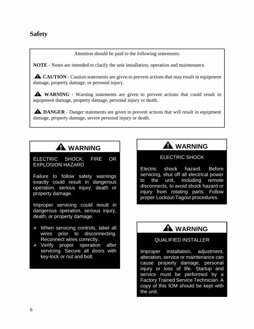
6
Safety
Attention should be paid to the following statements
NOTE - Notes are intended to clarify the unit installation operation and maintenance
CAUTION - Caution statements are given to prevent actions that may result in equipment
damage property damage or personal injury
WARNING - Warning statements are given to prevent actions that could result in
equipment damage property damage personal injury or death
DANGER - Danger statements are given to prevent actions that will result in equipment
damage property damage severe personal injury or death
QUALIFIED INSTALLER Improper installation adjustment alteration service or maintenance can cause property damage personal injury or loss of life Startup and service must be performed by a Factory Trained Service Technician A copy of this IOM should be kept with the unit
WARNING
ELECTRIC SHOCK Electric shock hazard Before servicing shut off all electrical power to the unit including remote disconnects to avoid shock hazard or injury from rotating parts Follow proper Lockout-Tagout procedures
WARNING
ELECTRIC SHOCK FIRE OR EXPLOSION HAZARD Failure to follow safety warnings exactly could result in dangerous operation serious injury death or property damage Improper servicing could result in dangerous operation serious injury death or property damage When servicing controls label all
wires prior to disconnecting Reconnect wires correctly
Verify proper operation after servicing Secure all doors with key-lock or nut and bolt
WARNING
7
ROTATING COMPONENTS Unit contains fans with moving parts that can cause serious injury Do not remove grill containing fans until the power to the unit has been disconnected and fan has stopped rotating
WARNING
LIVE ELECTRICAL During installation testing servicing and troubleshooting of the equipment it may be necessary to work with live electrical components Only a qualified licensed electrician or individual properly trained in handling live electrical components shall perform these tasks Standard NFPA-70E an OSHA regulation requiring an Arc Flash Boundary to be field established and marked for identification of where appropriate Personal Protective Equipment (PPE) be worn should be followed
WARNING
FIRE EXPLOSION OR CARBON MONOXIDE POISONING HAZARD Failure to replace proper controls could result in fire explosion or carbon monoxide poisoning Failure to follow safety warnings exactly could result in serious injury death or property damage Do not store or use gasoline or other flammable vapors and liquids in the vicinity of this appliance
WARNING
GROUNDING REQUIRED All field installed wiring must be completed by qualified personnel Field installed wiring must comply with NECCEC local and state electrical code requirements Failure to follow code requirements could result in serious injury or death Provide proper unit ground in accordance with these code requirements
WARNING
VARIABLE FREQUENCY DRIVES
Do not leave VFDs unattended in hand mode or manual bypass Damage to personnel or equipment can occur if left unattended When in hand mode or manual bypass mode VFDs will not respond to controls or alarms
WARNING
8
LEAK TESTING
Do not use oxygen acetylene or air in place of refrigerant and dry nitrogen for leak testing A violent explosion may result causing injury or death
WARNING
VARIABLE FREQUENCY DRIVES
Electric motor over-current protection and overload protection may be a function of the Variable Frequency Drive to which the motors are wired Never defeat the VFD motor overload feature The overload ampere setting must not exceed 115 of the electric motors FLA rating as shown on the motor nameplate
CAUTION
PVC PIPING
PVC (Polyvinyl Chloride) and CPVC (Chlorinated Polyvinyl Chloride) are vulnerable to attack by certain chemicals Polyolester (POE) oils used with R-410A and other refrigerants even in trace amounts in a PVC or CPVC piping system will result in stress cracking of the piping and fittings and complete piping system failure
CAUTION
3-PHASE ROTATION
Rotation must be checked on all MOTORS AND COMPRESSORS of 3 phase units at startup by a qualified service technician Scroll compressors are directional and can be damaged if rotated in the wrong direction Compressor rotation must be checked using suction and discharge gauges Fan motor rotation should be checked for proper operation Alterations should only be made at the unit power connection
CAUTION
UNIT HANDLING To prevent injury or death lifting equipment capacity shall exceed unit weight by an adequate safety factor Always test-lift unit not more than 24 inches high to verify proper center of gravity lift point to avoid unit damage injury or death
WARNING
DOOR LATCHES
Door compartments containing hazardous voltage or rotating parts are equipped with door latches that allow locks Door latches are shipped with a nut and bolt requiring tooled access If the shipping hardware is not replaced with a pad lock always re-install the nut and bolt after closing the door to maintain tooled access
CAUTION
9
ENCLOSED AREA
Do not work in an enclosed area where refrigerant or nitrogen gases may be leaking A sufficient quantity of vapors may be present and cause
injury or death
WARNING
COMPRESSOR LUBRICANT
Polyolester (POE) and Polyvinylether (PVE) oils are two types of lubricants used in hydrofluorocarbon (HFC) refrigeration systems Refer to the compressor label for the proper compressor lubricant type
CAUTION
COIL CLEANERS
To prevent damage to the unit do not use acidic chemical coil cleaners Do not use alkaline chemical coil cleaners with a pH value greater than 85 after mixing without first using an aluminum corrosion inhibitor in the cleaning solution
CAUTION
COIL CLEANERS
Some chemical coil cleaning compounds are caustic or toxic Use these substances only in accordance with the manufacturerrsquos usage instructions Failure to follow instructions may result in equipment damage injury or death
WARNING
COIL CLEANING
Do not clean DX refrigerant coils with hot water or steam The use of hot water or steam on refrigerant coils will cause high pressure inside the coil tubing and damage to the coil
CAUTION
CONVENIENCE OUTLETS
Factory installed convenience outlets are not intended for use while the unit is operating
WARNING
10
1 Startup and service must be performed by
a Factory Trained Service Technician
2 The unit is for outdoor use only See
General Information section for more
information
3 Every unit has a unique equipment
nameplate with electrical operational
and unit clearance specifications
Always refer to the unit nameplate for
specific ratings unique to the model
purchased
4 READ THE ENTIRE INSTALLATION
OPERATION AND MAINTENANCE
MANUAL OTHER IMPORTANT
SAFETY PRECAUTIONS ARE
PROVIDED THROUGHOUT THIS
MANUAL
5 Keep this manual and all literature
safeguarded near or on the unit
COMPRESSOR CYCLING
5 MINUTE MINIMUM OFF TIME To prevent motor overheating compressors must cycle off for a minimum of 5 minutes
5 MINUTE MINIMUM ON TIME To maintain the proper oil level compressors must cycle on for a minimum of 5 minutes The cycle rate must not exceed 6 starts per hour
WARNING
CF Series Feature String Nomenclature
Model Options Unit Feature Options G
EN
MJ
RE
V
SIZ
E
SE
RIE
S
MN
RE
V
VL
T
A1
A2
A3
A4
A5
1
2A
2B
3A
3B
4
5
6A
6B
6C
7
8A
8B
8C
8D
9
10
11
12
13
14
15
CF A - 015 - B - A - 3 - D C 0 0 K 0 - A 0 - E 0 - C 0 - A N 0 - B - D E 0 0 - 0 0 A 0 E 0 0
0 0 0 0 0 D B
16
17
18
19
20
21
22
11
CF Series Feature String Nomenclature
MODEL OPTIONS Series and Generation
CF
Major Revision
A
Unit Size
002 = 2 ton Capacity
003 = 3 ton Capacity
004 = 4 ton Capacity
005 = 5 ton Capacity
006 = 6 ton Capacity
007 = 7 ton Capacity
009 = 9 ton Capacity
011 = 11 ton Capacity
013 = 13 ton Capacity
015 = 15 ton Capacity
016 = 16 ton Capacity
018 = 18 ton Capacity
020 = 20 ton Capacity
025 = 25 ton Capacity
026 = 26 ton Capacity
030 = 30 ton Capacity
031 = 31 ton Capacity
040 = 40 ton Capacity
050 = 50 ton Capacity
060 = 60 ton Capacity
070 = 70 ton Capacity
Series
A = 2-7 ton units
B = 9-15 ton units
C = 16-25 amp 30 ton units
D = 26 amp 31-70 ton units
Minor Revision
A
Voltage
1 = 230V1Φ60Hz
2 = 230V3Φ60Hz
3 = 460V3Φ60Hz
4 = 575V3Φ60Hz
8 = 208V3Φ60Hz
9 = 208V1Φ60Hz
A1 Compressor Style
0 = Air-Cooled Condenser - No Compressors
(1 Circuit)
A = R-410A Scroll Compressors
B = R-410A Two Step Capacity Scroll Compressors
D = R-410A Variable Capacity Scroll Compressors
E = R-410A Tandem Scroll Compressors
G = R-410A Tandem Variable Capacity Scroll
Compressors
P = Air-Cooled Condenser - No Compressors
(2 Circuits)
Q = Air-Cooled Condenser - No Compressors
(4 Circuits)
A2 Condenser Style
C = Air-Cooled Condenser
J = Air-Source Heat Pump
A3 Configuration
0 = Standard
A4 Coating
0 = Standard
E = Polymer E-Coated Condenser Coil
G = Copper Fin + Stainless Steel Casing - Condenser
Coil
A5 Staging
0 = No Cooling
G = 1 OnOff Refrigeration System
H = 1 Variable Capacity Refrigeration System
J = 2 OnOff Refrigeration Systems
K = 1 Variable Capacity Refrigeration System + 1
OnOff Refrigeration System
L = 2 Variable Capacity Refrigeration System
R = 4 OnOff Refrigeration Systems
T = 2 Variable Capacity Refrigeration Systems + 2
OnOff Refrigeration Systems
U = 4 Variable Capacity Refrigeration Systems
CF Series Feature String Nomenclature
Model Options Unit Feature Options G
EN
MJR
EV
SIZ
E
SE
RIE
S
MN
RE
V
VL
T
A1
A2
A3
A4
A5
1
2A
2B
3A
3B
4
5
6A
6B
6C
7
8A
8B
8C
8D
9
10
11
12
13
14
15
CF A - 015 - B - A - 3 - D C 0 0 K 0 - A 0 - E 0 - C 0 - A N 0 - B - D E 0 0 - 0 0 A 0 E 0 0
0 0 0 0 0 D B
16
17
18
19
20
21
22
12
UNIT FEATURE OPTIONS 1 Unit Orientation
0 = Vertical Condenser Discharge - Standard Access
A = Horizontal Condenser Discharge - Standard
Access
2A Refrigeration Control
0 = Standard
A = 5 Minute Compressor Off Timer + 20 Second
Compressor Stage Delay
C = Adjustable Fan Cycling
D = Adjustable Compressor Lockout
G = Option A + Adjustable Fan Cycling
H = Option A + Adjustable Compressor Lockout
M = Adjustable Fan Cycling + Adjustable
Compressor Lockout
W = Option A + Adjustable Fan Cycling +
Adjustable Compressor Lockout
2B Blank
0 = Standard
3A Refrigeration Options
0 = Standard
A = Hot Gas Bypass Lead Stage [HGB]
B = HGB Lead + HGB Lag
D = Hot Gas Bypass Non-Variable Capacity
Refrigeration Systems [HGBNV]
E = Modulating Hot Gas Reheat [MHGR]
H = HGB + MHGR
J = HGB Lead + HGB Lag + MHGR
L = HGBNV + MHGR
3B Blank
0 = Standard
4 Refrigeration Accessories
0 = Standard
A = Sight Glass
B = Compressor Isolation Valves
C = Options A + B
D = Flooded Condenser 0degF Low Ambient Controls ndash
One Circuit
E = Options A + D
F = Options B + D
G = Options A + B + D
H = Flooded Condenser 0degF Low Ambient Controls-
Two Circuits
J = Options A + H
K = Options B + H
L = Options A + B + H
R = Flooded Condenser 0degF Low Ambient Controls ndash
Four Circuits
S = Options A + R
T = Options B + R
U = Options A + B + R
5 Blank
0 = Standard
6A Unit Disconnect Type
0 = Single Point Power Block
A = Single Point Power Non-Fused Disconnect
6B Disconnect 1 Size
0 = Standard
N = 100 amps
R = 150 amps
V = 250 amps
Z = 400 amps
6C Blank
0 = Standard
CF Series Feature String Nomenclature
Model Options Unit Feature Options
GE
N
MJR
EV
SIZ
E
SE
RIE
S
MN
RE
V
VL
T
A1
A2
A3
A4
A5
1
2A
2B
3A
3B
4
5
6A
6B
6C
7
8A
8B
8
C
8D
9
10
11
12
13
14
15
CF A - 015 - B - 0 - 3 - D C 0 0 K 0 - A 0 - E 0 - C 0 - A N 0 - B - D C 0 0 - 0 0 A 0 E 0 0 0 0 0 0 0 D B
16
17
18
19
20
21
22
13
7 Accessories
0 = Standard
B = Phase amp Brown Out Protection
D = Suction Pressure Transducer on Each
Refrigeration Circuit
E = Compressor Sound Blanket
L = Options B + D
M = Options B + E
Q = Options D + E
1 = Options B + D + E
8A Control Sequence
A = Terminal Block for Thermostat w Isolation
Relays
D = VAV Unit Controller - VAV Cool + CAV Heat
E = CAV Unit Controller
F = Makeup Air Unit Controller - CAV Cool + CAV
Heat
H = Constant Volume HP Unit Controller - CAV
Cool + CAV Heat
J = Makeup Air HP Unit Controller - CAV Cool +
CAV Heat
N = Field Installed DDC Controls by Others with
Isolation Relays
8B Control Suppliers
0 = Standard
E = Orion VCC-X (Main Controller in Air Handling
Unit)
H = AAON Touchscreen Controller (Main Controller
in Air Handling Unit)
8C Control Supplier Options
0 = Standard
8D BMS Connection amp Diagnostics
0 = Standard
9 Blank
0 = Standard
10 Blank
0 = Standard
11 Maintenance Accessories
0 = Standard
A = Factory Wired 115VAC Convenience Outlet
B = Field Wired 115VAC Convenience Outlet
C = Service Lights
E = Remote Unit StartStop Terminals
F = Options A + C
H = Options A + E
J = Options B + C
L = Options B + E
N = Options C + E
R = Options A + C + E
U = Options B + C + E
12 Code Options
0 = Standard ETL USA Listing
B = ETL USA + Canada Listing
13 Air-Cooled Condenser Accessories
0 = Standard
A = Condenser Coil Guard
C = ECM Condenser Fan Head Pressure Control
E = VFD Condenser Fan Head Pressure Control
G = Options A + C
J = Options A + E
N = ECM Condenser Fan Head Pressure Control +
Low Sound Condenser Fan
S = Options A + N
14 Blank
0 = Standard
15 Blank
0 = Standard
16 Electrical Options
0 = Standard
17 Shipping Options
0 = Standard
A = Crating
B = Export Crating
CF Series Feature String Nomenclature
Model Options Unit Feature Options G
EN
MJR
EV
SIZ
E
SE
RIE
S
MN
RE
V
VL
T
A1
A2
A3
A4
A5
1
2A
2B
3A
3B
4
5
6A
6B
6C
7
8A
8B
8C
8D
9
10
11
12
13
14
15
CF A - 015 - B - A - 3 - D C 0 0 K 0 - A 0 - E 0 - C 0 - A N 0 - B - D E 0 0 - 0 0 A 0 E 0 0
0 0 0 0 0 D B 1
6
17
18
19
20
21
22
14
18 Blank
0 = Standard
19 Blank
0 = Standard
20 Cabinet Material
0 = Galvanized Steel Cabinet
21 Warranty
0 = Standard
D = Compressor Warranty - Years 2-5
22 Type
B = Premium AAON Gray Paint Exterior
E = Premium AAON Gray Paint Ext + Shrink Wrap
X = SPA + Premium AAON Gray Paint Exterior
1 = SPA + Premium AAON Gray Paint Exterior +
Shrink Wrap
15
General Information
AAON CF Series air-cooled condensers and
condensing units have been designed for
outdoor use only They are factory
assembled wired charged and run-tested
Codes and Ordinances
CF Series units have been tested and
certified by ETL in accordance with UL
Safety Standard 1995CSA C222 No 236
System should be sized in accordance with
the American Society of Heating
Refrigeration and Air Conditioning
Engineers Handbook
Installation of CF Series units must conform
to the ICC standards of the International
Mechanical Code the International Building
Code and local building plumbing and
electrical codes All appliances must be
electrically grounded in accordance with
local codes or in the absence of local codes
the current National Electric Code
ANSINFPA 70 or the current Canadian
Electrical Code CSA C221
Receiving Unit
When received the unit should be checked
for damage that might have occurred in
transit If damage is found it should be noted
on the carrierrsquos freight bill A request for
inspection by carrierrsquos agent should be made
in writing at once Nameplate should be
checked to ensure the correct model sizes and
voltages have been received to match the job
requirements
If repairs must be made to damaged goods
then the factory should be notified before any
repair action is taken in order to protect the
warranty Certain equipment alteration
repair and manipulation of equipment
without the manufacturerrsquos consent may void
the product warranty Contact AAON
Technical Support for assistance with
handling damaged goods repairs and freight
claims (918) 382-6450
SHARP EDGES
Coils and sheet metal surfaces present sharp edges and care must be taken when working with equipment
WARNING
QUALIFIED INSTALLER
Improper installation adjustment alteration service or maintenance can cause property damage personal injury or loss of life Installation and service must be performed by a Factory Trained Service Technician
WARNING
Failure to observe the following instructions will result in premature failure of your system and possible voiding of the warranty
WARNING
16
Storage
If installation will not occur immediately
following delivery store equipment in a dry
protected area away from construction traffic
and in the proper orientation as marked on the
packaging with all internal packaging in
place Secure all loose-shipped items
Failure to observe the following instructions
will result in premature failure of your
system and possible voiding of the warranty
Never turn off the main power supply to the
unit except for complete shutdown When
power is cut off from the unit any
compressors using crankcase heaters cannot
prevent refrigerant migration This means the
compressor will cool down and liquid
refrigerant may accumulate in the
compressor The compressor is designed to
pump refrigerant gas and damage may occur
if liquid enters the compressor when power is
restored
Before unit operation the main power switch
must be turned on for at least twenty-four
hours for units with compressor crankcase
heaters This will give the crankcase heater
time to clear any liquid accumulation out of
the compressor before it is required to run
Always control the system from the control
panel never at the main power supply (except
for emergency or for complete shutdown of
the system)
CLEAN AIR ACT
The Clean Air Act of 1990 bans the intentional venting of refrigerant as of July 1 1992 Approved methods of recovery recycling or reclaiming must be followed
CAUTION
CRANKCASE HEATER OPERATION
Units are equipped with compressor crankcase heaters which should be energized at least 24 hours prior to cooling operation to clear any liquid refrigerant from the compressors
CAUTION
3-PHASE ROTATION
Rotation must be checked on all MOTORS AND COMPRESSORS of three phase units All motors to include and not be limited to pump motors and condenser fan motors should all be checked by a qualified service technician at startup and any wiring alteration should only be made at the unit power connection
CAUTION
17
The standard compressors must be on a
minimum of 5 minutes and off for a minimum
of 5 minutes The cycle rate must be no more
than 6 starts per hour
The variable capacity compressors must be
on a minimum of 3 minutes and off for a
minimum of 3 minutes The cycle rate must
be no more than 6 starts per hour
The compressor life will be seriously
shortened by reduced lubrication and the
pumping of excessive amounts of liquid oil
and liquid refrigerant
Wiring Diagrams
A complete set of unit specific wiring
diagram in point-to-point form is laminated
in plastic and located inside the control
compartment door
General Maintenance
When the initial startup is made and on a
periodic schedule during operation it is
necessary to perform routine service checks
on the performance of the condensing unit
This includes reading and recording suction
pressures and checking for normal sub-
cooling and superheat
COMPRESSOR ROTATION
Scroll compressors are directional and will be damaged by operation in the wrong direction Low pressure switches on compressors have been disconnected after factory testing Rotation should be checked by a qualified service technician at startup using suction and discharge pressure gauges and any wiring alteration should only be made at the unit power connection
COMPRESSOR CYCLING
5 MINUTE MINIMUM OFF TIME To prevent motor overheating compressors must cycle off for a minimum of 5 minutes
5 MINUTE MINIMUM ON TIME To maintain the proper oil level compressors must cycle on for a minimum of 5 minutes The cycle rate must not exceed 6 starts per hour
WARNING
CAUTION
18
Installation
Forklifting the Unit
CF Series condensing unit sizes 2-25 amp 30
tons can be lifted using a forklift 2-7 ton
units must have forks at least 48rdquo in length
9-25 amp 30 ton units must have forks 72rdquo in
length or the forks must have 72rdquo fork
extensions Standard units can be lifted from
all sides except the condenser coil side CF
Series condensing unit sizes 26 amp 31-70 tons
cannot be lifted using a forklift They can be
lifted as shown in Figure 3
Forks must be perpendicular to the unit and
they must be in far enough that the back of
the forks are no more than 6rdquo away from the
edge of the unit
Figure 1 - Forklifting a CF Series A Cabinet
Figure 2 - Forklifting a CF Series B and C
Cabinet
FORKLIFTING 2-7 TON UNITS
Forks or Fork Extensions must be at least 48rdquo in length
CAUTION
FORKLIFTING 9-25 amp 30 TON UNITS
Forks or Fork Extensions must be at least 72rdquo in length
CAUTION
19
Lifting the Unit
If cables or chains are used to hoist the unit
they must be the same length Minimum
cable length is 99rdquo for CF Series 9-70 ton
units CF Series 2-7 ton units do not include
factory installed lifting lugs and should be
lifted by forklift only Care should be taken
to prevent damage to the cabinet coils and
condenser fans
Before lifting unit be sure that all shipping
material has been removed from unit Secure
hooks and cables at all lifting points lugs
provided on the unit
Figure 3 ndash Lifting Details and Orientation of
a CF Series 9-70 ton Condensing Unit
Locating the Unit
The CF Series condenser and condensing unit
is designed for outdoor applications and
mounting at ground level or on a rooftop It
must be placed on a level and solid
foundation that has been prepared to support
its weight When installed at ground level a
one-piece concrete slab should be used with
footings that extend below the frost line Also
with ground level installation care must be
taken to protect the coil fins from damage due
to vandalism or other causes
The first clearance table below gives the
clearance values for proper unit operation
The second clearance table gives the
clearance necessary for removing the coil
without disassembling a large part of the
condensing unit For ease of removing the
condenser coil use the second table
clearances for the right hand side of the unit
Table 1 ndashClearances for Proper Operation
Location Unit Size
2-7 tons 9-70 tons
Front -
(Controls
Side)
Unobstructed 36rdquo
Left Side 6rdquo 30rdquo
Right Side 6rdquo 36rdquo
Top 3rdquo Unobstructed
Back 18rdquo 6rdquo
Table 2 ndash Clearances for Coil Pull
Unit Size Right Hand Side
2-7 tons 42rdquo
9-15 tons 42rdquo
16-25 amp 30 tons 54rdquo
26 amp 31-70 tons 66rdquo
Figure 4 - Orientation of Series 2-7 ton
Condensing Unit
20
The placement relative to the building air
intakes and other structures must be carefully
selected Airflow to and from the condenser
or condensing unit must not be restricted to
prevent a decrease in performance and
efficiency
The installation position for 9-70 ton units
must provide at least 30rdquo of left and right side
clearance for proper airflow to the condenser
coils When units are mounted adjacent to
each other the minimum right and left side
clearance required between the units is 60rdquo or
5 feet Similarly when 2-7 ton units are
mounted adjacent to each other the minimum
clearance required between the back side of
the units is 36rdquo or 3 feet
Units should not be installed in an enclosure
or pit that is deeper than the height of the unit
When recessed installation is necessary the
clearance to maintain proper airflow is at
least 5 feet (3 feet for 2-7tons)
CF Series condensers and condensing units
that have a vertical air discharge must have
no obstruction above the equipment Do not
place the unit under an overhang CF Series
condensers and condensing units that have a
horizontal discharge must have no
obstruction in front of the unit
For proper unit operation the immediate area
around condenser must remain free of debris
that may be drawn in and obstruct airflow in
the condensing section
Consideration must be given to obstruction
caused by snow accumulation when placing
the unit
Mounting Isolation
For roof mounted applications or anytime
vibration transmission is a factor vibration
isolators may be used
Access Doors
Access doors are provided to the compressor
and electrical compartment
Standard Evacuation Instructions
Proper system evacuation is critical to
remove moisture and non-condensables from
the system before charging the system with
refrigerant A newly installed AAON
condensing unit has already been evacuated
and charged with some refrigerant at the
factory When evacuating a new system
keep the condensing unit service valves
closed and evacuate the suction and liquid
lines and the air handling unit If the entire
system must be evacuated use the following
procedure to ensure the entire system is
pulled into a good vacuum
1 System evacuation should be
performed anytime a system is open to
atmospheric pressure The POE oils
used with R-410A are extremely
hydroscopic in nature and immediately
begin pulling in moisture once the
system is opened to the atmosphere
2 Before starting to evacuate the
system you MUST ensure that there are
no leaks by pressurizing the system with
PVC PIPING
PVC (Polyvinyl Chloride) and CPVC (Chlorinated Polyvinyl Chloride) are vulnerable to attack by certain chemicals Polyolester (POE) oils used with R-410A and other refrigerants even in trace amounts in a PVC or CPVC piping system will result in stress cracking of the piping and fittings and complete piping system failure
CAUTION
21
400 psig of dry nitrogen and verifying no
pressure loss after one hour
3 Four valve manifold gauge sets are
more effective than standard manifold
gauge sets due to the extra hose port in
combination with a 38rsquorsquo evacuation
port The larger diameter evacuation port
will expedite system evacuation
4 The manifold set should be connected
to the condensing unit with one hose on
the suction line service valve one hose
on the liquid line service valve and if an
extra Schrader valve is field installed on
the suction line connect a third hose (not
shown) The vacuum pump should be
connected to the manifold set using a
38rdquo vacuum rated hose Figure 5 shows
two circuits Both circuits must be
evacuated separately
Figure 5 ndash CU evacuation connections
5 An accurate micron gauge must be
used and checked by pulling a vacuum
on the gauge by itself and verify a rapid
drop to less than 100 microns within a
few minutes
6 The micron gauge should not be
attached to the system until the gauge
manifold is reading 28rsquorsquo of vacuum to
ensure the micron gauge does not see
pressure and is thus damaged MICRON
GAUGES WILL BE DAMAGED BY
PRESSURE
7 It is a good practice to replace the
vacuum pump oil after one hour of the
evacuation process The oil can be
broken down in the pump in the initial
first hour causing system evacuation to
take longer than it should
8 The minimum micron level required
by AAON is 350 microns for systems
using POE oils
9 The system should then be isolated
and the pump turned off to check for
vacuum rise due to leaks or moisture in
the system The micron gauge should
not rise above 500 microns after 30
minutes of wait time
Low Ambient amp Modulating Reheat
System Evacuation Instructions
Proper system evacuation is critical to
remove moisture and non-condensables from
the system before charging the system with
refrigerant Systems with low ambient
flooded condenser option require the
following procedure to ensure the entire
system is pulled into a good vacuum
1 System evacuation should be
performed anytime a system is open to
atmospheric pressure The POE oils
used with R-410A are extremely
hydroscopic in nature and immediately
begin pulling in moisture once the
system is opened to the atmosphere
2 Open the reheat valve to 50 when
evacuating
3 Before starting to evacuate the
system you MUST ensure that there are
no leaks by pressurizing the system with
22
400 psig of dry nitrogen and verifying no
pressure loss after one hour
4 Four valve manifold gauge sets are
more effective than standard manifold
gauge sets due to the extra hose port in
combination with a 38rsquorsquo evacuation
port The larger diameter evacuation port
will expedite system evacuation
5 The manifold set should be connected
to the condensing unit with one hose on
the suction line service valve one hose
on the liquid line service valve and a
third hose on the reheat line service
valve The vacuum pump should be
connected to the manifold set using a
38rdquo vacuum rated hose Figure 6 shows
two circuits The first circuit has a
reheat line the second circuit is just the
suction and liquid line Both circuits
must be evacuated separately
Figure 6 ndash CU evacuation connections
6 FAILURE to connect to the liquid
line service valve will result in the
receiver tank not being fully evacuated
and most likely lead to non-
condensables in the system
7 An accurate micron gauge must be
used and checked by pulling a vacuum
on the gauge by itself and verify a rapid
drop to less than 100 microns within a
few minutes
8 The micron gauge should not be
attached to the system until the gauge
manifold is reading 28rsquorsquo of vacuum to
ensure the micron gauge does not see
pressure and is thus damaged MICRON
GAUGES WILL BE DAMAGED BY
PRESSURE
9 It is a good practice to replace the
vacuum pump oil after one hour of the
evacuation process The oil can be
broken down in the pump in the initial
first hour causing system evacuation to
take longer than it should
10 The minimum micron level required
by AAON is 350 microns for systems
using POE oils
11 The system should then be isolated
and the pump turned off to check for
vacuum rise due to leaks or moisture in
the system The micron gauge should
not rise above 500 microns after 30
minutes of wait time
Adjusting Refrigerant Charge
All AAON CF Series condensers and
condensing units are shipped with a factory
holding charge The factory charge is
different depending on the unit size and
system (heat pump modulating hot gas
reheat LAC) The factory charge per circuit
is shown on the unit nameplate Adjusting the
charge of the system will be required during
installation
23
Adjusting the charge of a system in the field
must be based on determination of liquid sub-
cooling and evaporator superheat On a
system with a thermostatic expansion valve
liquid sub-cooling is more representative of
the charge than evaporator superheat but both
measurements must be taken
Before Charging
Refer to the Unit Nameplate to determine
which refrigerant must be used to charge the
system
Unit being charged must be at or near full
load conditions before adjusting the charge
Units equipped with hot gas bypass must
have the hot gas bypass valve closed to get
the proper charge
Units equipped with hot gas reheat must be
charged with the hot gas valve closed while
the unit is in cooling mode After charging
unit should be operated in reheat
(dehumidification) mode to check for correct
operation
Units equipped with heat pump options
should be charged in cooling mode to get the
proper charge After charging unit should be
operated in heating mode to check for correct
charge Charge may need to be adjusted for
heating mode If adjustments are made in the
heating mode cooling mode must be rerun to
verify proper operation
After adding or removing charge the system
must be allowed to stabilize typically 10-15
minutes before making any other
adjustments
The type of unit and options determine the
ranges for liquid sub-cooling and evaporator
superheat Refer to Table 3 when determining
the proper sub-cooling
For units equipped with low ambient (0degF)
option see the special charging instructions at
the end of this section
Checking Liquid Sub-cooling
Measure the temperature of the liquid line as
it leaves the condenser coil
Read the gauge pressure at the liquid line
close to the point where the temperature was
taken You must use liquid line pressure as it
will vary from discharge pressure due to
condenser coil pressure drop
Convert the pressure obtained to a saturated
temperature using the appropriate refrigerant
temperature-pressure chart
COMPRESSOR LUBRICANT
Polyolester (POE) and Polyvinylether (PVE) oils are two types of lubricants used in hydrofluorocarbon (HFC) refrigeration systems Refer to the compressor label for the proper compressor lubricant type
CAUTION
CLEAN AIR ACT
The Clean Air Act of 1990 bans the intentional venting of refrigerant (CFCrsquos and HCFCrsquos) as of July 1 1992 Approved methods of recovery recycling or reclaiming must be followed Fines andor incarceration may be levied for non-compliance
CAUTION
24
Subtract the measured liquid line temperature
from the saturated temperature to determine
the liquid sub-cooling
Compare calculated sub-cooling to Table 3
for the appropriate unit type and options
Table 3 - Acceptable Refrigeration Circuit
Values
Cooling
Mode
Liquid Sub-
Cooling
Values
Cooling Only Unit4 8-15degF
Cooling Only Unit with Hot
Gas Reheat14 5-15degF
Heat PumpUnit24 2-4degF
Heat Pump Unit with Hot
Gas Reheat34 2-6degF
Cooling Only Unit with
LAC4 8-15degF
Cooling Only Unit with Hot
Gas Reheat amp LAC4 8-15degF
Notes 1 Must be charged with the hot gas valve
closed After charging unit should be
operated in reheat (dehumidification) mode
to check for correct operation
2 The sub-cooling value in this table is for the
unit running in cooling mode of operation
After charging unit should be operated in
heating mode to check for correct operation
3 The sub-cooling value in this table is for the
unit running in cooling mode of operation
and the hot gas valve closed After charging
unit should be operated in reheat
(dehumidification) mode to check for correct
operation and then in heating mode to check
for correct operation
4 Sub-cooling must be increased by 1degF per 10
feet of vertical liquid line rise for R-410A
(AHU above CU) For example a cooling
only unit with hot gas reheat and a vertical
liquid drop can charge to a sub-cooling value
of 5-15degF but a cooling only unit with hot
gas reheat and a vertical liquid rise of 30 ft
must charge to a sub-cooling value of at least
8-15degF DO NOT OVERCHARGE
Refrigerant overcharging leads to excess
refrigerant in the condenser coils resulting in
elevated compressor discharge pressure
Checking Evaporator Superheat
Measure the temperature of the suction line
close to the compressor
Read gauge pressure at the suction line close
to the compressor
Convert the pressure obtained to a saturated
temperature using the appropriate refrigerant
temperature-pressure chart
Subtract the saturated temperature from the
measured suction line temperature to
determine the evaporator superheat
For refrigeration systems with tandem
compressors it is critical that the suction
superheat setpoint on the TXV is set with one
compressor running The suction superheat
should be 10-13degF with one compressor
running The suction superheat will increase
with both compressors in a tandem running
Inadequate suction superheat can allow liquid
refrigerant to return to the compressors which
will wash the oil out of the compressor Lack
of oil lubrication will destroy a compressor
Liquid sub-cooling should be measured with
both compressors in a refrigeration system
running
Compare calculated superheat to the
acceptable cooling mode superheat values of
8-15degF for all system types Superheat will
increase with long suction line runs
25
Adjusting Sub-cooling and Superheat
Temperatures
The system is overcharged if the sub-cooling
temperature is too high compared to Table 3
and the evaporator is fully loaded (low loads
on the evaporator result in increased sub-
cooling) and the evaporator superheat is
within the temperature range of 8-15degF (high
superheat results in increased sub-cooling)
Correct an overcharged system by reducing
the amount of refrigerant in the system to
lower the sub-cooling
The system is undercharged if the superheat
is too high and the sub-cooling is too low
Correct an undercharged system by adding
refrigerant to the system to reduce superheat
and raise sub-cooling
If the sub-cooling is correct and the superheat
is too high the TXV may need adjustment to
correct the superheat
DO NOT OVERCHARGE Refrigerant overcharging leads to excess refrigerant in the condenser coils resulting in elevated compressor discharge pressure
CAUTION
EXPANSION VALVE ADJUSTMENT
Thermal expansion valves must be adjusted to approximately 8-15degF of suction superheat Failure to have sufficient superheat will damage the compressor and void the warranty
CAUTION
26
Special Low Ambient Option Charging
Instructions
For units equipped with low ambient
refrigerant flood back option being charged
in the summer when the ambient
temperature is warm
If the ambient is above 70degF charge to
approximately 1-2degF of sub-cooling
measured at the inlet to the expansion valve
Once enough charge has been added to get
the evaporator superheat and sub-cooling
values to the correct setting more charge
must be added Use Table 4 to find the
additional charge amount required for the
system when running in cold ambient
conditions
Table 4 ndash Charge to Flood Condenser Coil
for Ambient Above 70degF
CF Size of
circuits
Per Circuit
Charge (lbs)
CF 2 3 1 49
CF 4 5 6 7 1 92
CF 9 11 2 91
CF 13 15 2 121
CF 16 18 2 131
CF 20 25 30 2 175
CF 26 31 40 2 180
4 91
CF 50 60 70 2 438
4 221
For units equipped with low ambient
refrigerant flood back option being charged
in the winter when the ambient
temperature is cold
1 If the ambient is below 70degF charge
to approximately 1-2degF of sub-cooling
measured at the inlet to the expansion
valve Once enough charge has been
added to get the evaporator superheat
and sub-cooling values to the correct
setting more charge may need to be
added If the ambient temperature is 0degF
no more charge is required Ambient
temperatures above 0degF will require a
percentage of the per circuit charge
values from Table 4 Using your
ambient temperature find the
percentage value from Table 5 and
multiply the Per Circuit Charge value
from Table 4 and the value to
determine the additional charge amount
Table 5 ndash Charge to Flood Condenser
Coil for Ambient Below 70degF
Condenser
Ambient
Temperature ˚F
Percentage
Per Circuit
Charge from
Table 4
60 60
50 37
40 24
30 15
20 8
0 0
2 The unit should be checked for proper
operation once the ambient temperature
is above 80degF
Example A CF size 31 with tandem
compressors where the ambient
temperature is 40degF
From Table 4 ndash 18 lbs refrigerant charge
per circuit (tandem compressors would
have 2 circuits in this size of CF)
From Table 5 ndash 24 of Table 4 charge
Additional charge needed for a unit with
low ambient flooded condenser controls
= 18 lbs 024 = 432 lbs additional
refrigerant charge per circuit
27
Low Ambient Operation
During low ambient temperatures the vapor
refrigerant will migrate to the cold part of the
system and condense into liquid All CF
Series compressors are provided with factory
installed crankcase heaters to help prevent
liquid refrigerant from slugging the
compressors during startup in low ambient
conditions The condenser or condensing unit
must have continuous power 24 hours prior
to startup This ensures the compressor will
receive sufficient refrigerant vapor at startup
Standard units can operate down to 55degF
ambient temperature
AAON condenser fan head pressure control
units can operate down to 35degF ambient
temperature Three different condenser fan
head pressure control options available are
adjustable fan cycling ECM condenser fan
or VFD controlled condenser fans See
detailed information following
The AAON low ambient (condenser flood-
back) system is used to operate a refrigerant
system down to 0degF outside air temperature
See detailed information following
Fan Cycling Low Ambient
Adjustable fan cycling is a low ambient head
pressure control option that cycles the
condenser fans to maintain refrigerant circuit
head pressures at acceptable levels during
cooling operation The head pressure set
point (100-470 psi) and pressure differential
(35-200 psi) can be field adjusted using a
flathead screwdriver For example if the
head pressure is set to 300psi and the
differential is set to 100psi then fans will cut
in at 300psi and cut out at 200psi Fan
cycling and variable speed condenser fan
head pressure control options allow
mechanical cooling with ambient
temperatures down to 35degF
Figure 7 - Adjustable Fan Cycling Switch
Variable Speed Low Ambient
Variable speed condenser fan head pressure
control is a low ambient head pressure
control option that sends a variable signal in
relation to the refrigerant circuit head
pressure of the system to an electronically
commutated motor (ECM) or VFD The
motor either speeds up or slows down air
flow accordingly in order to maintain
constant head pressure Fan cycling and
variable speed condenser fan head pressure
control options allow mechanical cooling
with ambient temperatures down to 35degF
Flooded Condenser Low Ambient
Flooded condenser low ambient control
maintains normal head pressure during
periods of low ambient When the ambient
temperature drops the condensing
temperature and therefore pressure drops
Without ambient control the system would
shut down on low discharge pressure The
flooded condenser method of low ambient
control fills the condenser coil with liquid
refrigerant decreasing the heat transfer
capacity of the coil which allows the coil to
operate at an acceptable discharge pressure
28
The condenser coil will not be flooded during
summer ambient temperatures so a receiver
is included to store the additional liquid
refrigerant required to flood the condenser
coil in low ambient The receiver is factory-
sized to contain all of the flooded volume
Without a receiver there would be high head
pressures during higher ambient conditions
The low ambient system maintains normal
head pressure during periods of low ambient
by restricting liquid flow from the condenser
to the receiver and at the same time
bypassing hot gas around the condenser to the
inlet of the receiver This reduces liquid
refrigerant flow from the condenser reducing
its effective surface area which in turn
increases the condensing pressure At the
same time the bypassed hot gas raises liquid
pressure in the receiver allowing the system
to operate properly CF Series condensers
and condensing units use an LAC valve for
low ambient operation
LAC Valve
The Low Ambient Control (LAC) valve is a
non-adjustable three way valve that
modulates to maintain receiver pressure As
the receiver pressure drops below the valve
setting (295 psig for R-410A) the valve
modulates to bypass discharge gas around the
condenser The discharge gas warms the
liquid in the receiver and raises the pressure
to the valve setting The following schematic
shows an example system using the LAC
valve
Figure 8 ndash LAC Piping Example
29
Refrigerant Piping
(See back of the manual for refrigerant piping
diagrams)
General
Piping from the condensing unit to the air
handler is the responsibility of the installing
contractor
Use only clean type ldquoACRrdquo copper tubing
that has been joined with high temperature
brazing alloy
The pipe or line sizes must be selected to
meet the actual installation conditions and
NOT simply based on the connection sizes at
the condensing unit or air handler
All CF Series condensing units are provided
with in-line shutoff valves on both the liquid
and suction lines These should remain closed
until the system is ready for start-up after
installation
Piping should conform to generally accepted
practices and codes
Care must be taken not to cross the circuits
on multiple circuit systems
Upon completion of piping connection the
interconnecting piping and air handler MUST
BE evacuated to 500 microns or less leak
checked and charged with refrigerant
Determining Refrigerant Line Size
The piping between the condenser and low
side must ensure
1 Minimum pressure drop and
2 Continuous oil return and
3 Prevention of liquid refrigerant slugging
or carryover
Minimizing the refrigerant line size is
favorable from an economic perspective
reducing installation costs and reducing the
potential for leakage However as pipe
diameters decrease pressure drop increases
Excessive suction line pressure drop causes
loss of compressor capacity and increased
power usage resulting in reduced system
efficiency Excessive pressure drops in the
liquid line can cause the liquid refrigerant to
flash resulting in faulty TXV operation and
improper system performance In order to
operate efficiently and cost effectively while
avoiding malfunction refrigeration systems
must be designed to minimize both cost and
pressure loss
REFRIGERANT PIPING
Line sizes must be selected to meet actual installation conditions not simply based on the connection sizes at the condensing unit or air handling unit
CAUTION
REFRIGERANT PIPING
This section is for information only and is not intended to provide all details required by the designer or installer of the refrigerant piping between the condenser or condensing unit and the air handling unit AAON Inc is not responsible for interconnecting refrigerant piping Consult ASHRAE Handbook ndash Refrigeration and ASME Standards
CAUTION
30
Equivalent Line Length
All line lengths discussed in this manual
unless specifically stated otherwise are
Equivalent Line Lengths The frictional
pressure drop through valves fittings and
accessories is determined by establishing the
equivalent length of straight pipe of the same
diameter Always use equivalent line
lengths when calculating pressure drop
Special piping provisions must be taken
when lines are up vertical risers or in
excessively long line runs AAON does not
recommend running underground
refrigerant lines
Liquid Line
When sizing the liquid line it is important to
minimize the refrigerant charge to reduce
installation costs and improve system
reliability This can be achieved by
minimizing the liquid line diameter
However reducing the pipe diameter will
increase the velocity of the liquid refrigerant
which increases the frictional pressure drop
in the liquid line and causes other
undesirable effects such as noise
Maintaining the pressure in the liquid line is
critical to ensuring sufficient saturation
temperature avoiding flashing upstream of
the TXV and maintaining system efficiency
Pressure losses through the liquid line due to
frictional contact installed accessories and
vertical risers are inevitable Maintaining
adequate sub-cooling at the condenser to
overcome these losses is the only method to
ensure that liquid refrigerant reaches the
TXV
Liquid refrigerant traveling upwards in a riser
loses head pressure If the evaporator is
below the condenser with the liquid line
flowing down the gravitational force will
increase the pressure of the liquid refrigerant
This will allow the refrigerant to withstand
greater frictional losses without the
occurrence of flashing prior to the TXV
A moisture-indicating sight glass may be
field installed in the liquid line to indicate the
occurrence of premature flashing or moisture
in the line The sight glass should not be used
to determine if the system is properly
charged Use temperature and pressure
measurements to determine liquid sub-
cooling not the sight glass
Liquid Line Routing
Care should be taken with vertical risers
When the system is shut down gravity will
pull liquid down the vertical column and
back to the condenser when it is below the
evaporator This could potentially result in
compressor flooding A check valve can be
installed in the liquid line where the liquid
column rises above the condenser to prevent
this The liquid line is typically pitched along
with the suction line or hot gas line to
minimize the complexity of the
configuration
Liquid Line Insulation
In cooling only systems when the liquid line
is routed through regions where temperature
losses are expected no insulation is required
as this may provide additional sub-cooling to
the refrigerant When routing the liquid line
through high temperature areas insulation of
the line is appropriate to avoid loss of sub-
cooling through heat gain
In heat pump systems when the liquid line is
routed through regions where temperature
losses are expected (all lines exposed to
outside air conditions) insulate with a
minimum 1 inch thick Armaflex insulation
as this will prevent capacity loss during
heating mode of operation
31
Liquid Line Guidelines
In order to ensure liquid at the TXV the sum
of frictional losses and pressure loss due to
vertical rise must not exceed available sub-
cooling A commonly used guideline to
consider is a system design with pressure
losses due to friction through the line not to
exceed a corresponding 1-2degF change in
saturation temperature An additional
recommendation is that the sum of frictional
losses (including valve losses filter drier
losses other accessories and line losses) and
pressure loss due to vertical rise should not
exceed 8degF if the available sub-cooling is
10degF
If the velocity of refrigerant in the liquid line
is too great it could cause excessive noise or
piping erosion The recommended maximum
velocities for liquid lines are 100 fpm from
the condenser to a receiver to discourage
fluid backup and 500 fpm from receiver tank
to the evaporator (300 fpm if the line includes
an electric valve to minimize valve induced
liquid hammer)
Liquid Line Accessories
Liquid line shut off valves and filter driers are
factory provided The total length equivalent
of pressure losses through valves elbows and
fittings must be considered when adding
additional components in the field It is a
good practice to utilize the fewest elbows that
will allow the mating units to be successfully
joined
A liquid line receiver is factory installed on
units with modulating hot gas reheat units
with low ambient control flooded condenser
and units with heat pump
Suction Line
The suction line is more critical than the
liquid line from a design and construction
standpoint More care must be taken to
ensure that adequate velocity is achieved to
return oil to the compressor at minimum
loading conditions However reducing the
piping diameter to increase the velocity at
minimal load can result in excessive pressure
losses capacity reduction and noise at full
load
Suction Line Routing
For cooling only systems pitch the suction
line in the direction of flow (about 1 inch per
20 feet of length) to maintain oil flow
towards the compressor and keep it from
flooding back into the evaporator
For heat pump systems do not pitch lines
since they will be flowing in one direction in
cooling mode and the opposite direction in
heating mode
Crankcase heaters are provided to keep any
condensed refrigerant that collects in the
compressor from causing damage or wear
Make sure to provide support to maintain
suction line positioning and insulate
completely between the evaporator and
condensing unit
It is important to consider part load operation
when sizing suction lines At minimum
capacity refrigerant velocity may not be
adequate to return oil up the vertical riser
Decreasing the diameter of the vertical riser
will increase the velocity but also the
frictional loss
For difficult line routing applications a
double suction riser can be applied to the
situation of part load operation with a suction
riser A double suction riser is designed to
return oil at minimum load while not
incurring excessive frictional losses at full
load A double suction riser consists of a
small diameter riser in parallel with a larger
diameter riser and a trap at the base of the
large riser At minimum capacity refrigerant
velocity is not sufficient to carry oil up both
32
risers and it collects in the trap effectively
closing off the larger diameter riser and
diverting refrigerant up the small riser where
velocity of the refrigerant is sufficient to
maintain oil flow At full load the mass flow
clears the trap of oil and refrigerant is carried
through both risers The smaller diameter
pipe should be sized to return oil at minimum
load while the larger diameter pipe should be
sized so that flow through both pipes
provides acceptable pressure drop at full
load
Figure 9 - Double Suction Riser
Construction
A double riser can also be used for heat pump
operation The specific volume (ft3lb) of
refrigerant at the discharge temperature and
pressure (heating mode line conditions) is
significantly lower than the specific volume
at the suction temperature and pressure
(cooling mode line conditions) To
compound the issue the capacity in heating
mode is lower than the capacity in cooling
mode The discharge velocity in the riser
during heating mode is much lower than the
suction velocity during cooling mode Often
a double riser is necessary to get acceptable
velocities for the discharge mode and
acceptable velocities for the suction mode In
the example diagrams (See Figure 10 amp
Figure 11) the cooling mode will use both
lines and the heating mode will use only one
Suction Line Traps
Include a trap immediately after the
evaporator coil outlet to protect the TXV bulb
from liquid refrigerant
Include traps every 20 feet in vertical suction
riser sections for cooling only systems and
every 12 feet for heat pump systems
Suction Line Insulation
The entire suction line should be insulated
with a minimum 1 inch thick Armaflex
insulation This prevents condensation from
forming on the line and reduces any potential
loss in capacity associated with heat gain
placing additional load on the system This
line should still be insulated in heat pump
systems even though it acts as both a
discharge and suction line
Suction Line Guidelines
For proper performance suction line
velocities less than a 4000 fpm maximum are
recommended The minimum velocity
required to return oil is dependent on the pipe
diameter however a general guideline of
1000 fpm minimum may be applied
When suction flow is up variable capacity
compressors require a minimum velocity of
1500 fpm at full load
Tandem compressors must be considered for
full load operation (both compressors
operating) and at partial load (only one
compressor operating) When suction flow is
up and the tandem has a variable capacity
compressor the velocity for only one
compressor in operation must be greater than
1500 fpm For onoff compressors the
velocity must be greater than the minimum
velocity required to return oil
Heat pump vapor lines must be checked for
suction flow (cooling mode operation) and
discharge flow (heating mode operation)
33
The same line must be used for both modes
of operation
In a fashion similar to the liquid line a
common guideline to consider is a system
design with pressure losses due to friction
through the line not to exceed a
corresponding 1-2degF change in saturation
temperature
For split system piping with long horizontal
runs and short vertical risers a smaller pipe
size can be used to provide sufficient velocity
to return oil in vertical risers at part loads and
a larger size pipe can be used on the
horizontal runs and vertical drop sections
This helps with oil return yet keeps the
pressure drop to a minimum
Suction Line Accessories
If the job requirements specify suction
accumulators they must be separately
purchased and field installed Heat pump
units will include a factory installed suction
accumulator
Discharge Line
The discharge line is similar to the suction
line from a design and construction
standpoint Care must be taken to ensure that
adequate velocity is achieved to return oil to
the compressor at minimum loading
conditions However reducing the piping
diameter to increase the velocity at minimal
load can result in excessive pressure losses
capacity reduction and noise at full load
Pressure loss in the discharge line has less of
an impact on capacity than pressure loss in
the suction line Pressure loss in the
discharge line causes the compressors to
work harder and thus use more power
Discharge Line Routing
For cooling only remote condenser systems
pitch the discharge line in the direction of
flow (about 1 inch per 20 feet of length) to
maintain oil flow towards the compressor
In a heat pump system the field installed
suction line is also used as a discharge line in
the heating mode of operation so the line
must be sized to meet both the suction line
conditions in cooling mode and the discharge
line conditions in heating mode
Because it is used in both directions for a heat
pump unit the line should be installed level
not pitched to facilitate oil return in both
modes of operation
It is important to consider part load operation
when sizing discharge lines At minimum
capacity refrigerant velocity may not be
adequate to return oil up the vertical riser
Decreasing the diameter of the vertical riser
will increase the velocity but also the
frictional loss
For difficult line routing applications a
double discharge riser can be applied to the
situation of part load operation with a
discharge riser A double discharge riser is
designed to return oil at minimum load while
not incurring excessive frictional losses at
full load A double discharge riser consists of
a small diameter riser in parallel with a larger
diameter riser and a trap at the base of the
large riser At minimum capacity refrigerant
velocity is not sufficient to carry oil up both
risers and it collects in the trap effectively
closing off the larger diameter riser and
diverting refrigerant up the small riser where
SUCTION RISER TRAPS
Circuits require suction riser traps every 20 feet (every 12 feet for heat pumps)
CAUTION
34
velocity of the refrigerant is sufficient to
maintain oil flow At full load the mass flow
clears the trap of oil and refrigerant is carried
through both risers The smaller diameter
pipe should be sized to return oil at minimum
load while the larger diameter pipe should be
sized so that flow through both pipes
provides acceptable pressure drop at full
load (See the Double Suction Riser
Construction Figure 9)
A double riser can also be used for heat pump
operation The specific volume (ft3lb) of
refrigerant at the discharge temperature and
pressure (heating mode line conditions) is
significantly lower than the specific volume
at the suction temperature and pressure
(cooling mode line conditions) To
compound the issue the capacity in heating
mode is lower than the capacity in cooling
mode The discharge velocity in the riser
during heating mode is much lower than the
suction velocity during cooling mode Often
a double riser is necessary to get acceptable
velocities for the discharge mode and
acceptable velocities for the suction mode In
the example diagrams the cooling mode will
use both lines and the heating mode will use
only one See the following schematics that
illustrate how the double discharge riser can
work for heat pump applications
Figure 10 ndash Heat Pump Piping Schematic of
Cooling Mode in Double Riser
Figure 11 ndash Heat Pump Piping Schematic of
Heating Mode in Double Riser
35
Discharge Line Traps
Include traps every 12 feet in vertical
discharge riser sections
Discharge Line Insulation
Although a typical discharge line does not
need to be insulated the suction line does
Since the same line is used for both the line
must be insulated as described in the Suction
Line Insulation section
Discharge Line Guidelines
For proper performance discharge line
velocities less than a 3500 fpm maximum are
recommended The minimum velocity
required to return oil is dependent on the pipe
diameter however a general guideline of
900 fpm minimum may be applied
When discharge flow is up variable capacity
compressors require a minimum velocity of
900 fpm at full load
Tandem compressors must be considered for
full load operation (both compressors
operating) and at partial load (only one
compressor operating) When discharge flow
is up and the tandem has a variable capacity
compressor the velocity for only one
compressor in operation must be greater than
900 fpm For onoff compressors the
velocity must be greater than the minimum
velocity required to return oil
Heat pump vapor lines must be checked for
suction flow (cooling mode operation) and
discharge flow (heating mode operation)
The same line must be used for both modes
of operation
In a fashion similar to the suction line a
common guideline to consider is a system
design with pressure losses due to friction
through the line not to exceed a
corresponding 1-2degF change in saturation
temperature
For split system piping with long horizontal
runs and short vertical risers a smaller pipe
size can be used to provide sufficient velocity
to return oil in vertical risers at part loads and
a larger size pipe can be used on the
horizontal runs and vertical drop sections
This helps with oil return yet keeps the
pressure drop to a minimum
Hot Gas Bypass Line
Hot Gas Bypass is available for use with DX
systems that may experience low suction
pressure during the operating cycle This may
be due to varying load conditions associated
with VAV applications or units supplying a
large percentage of outside air The system is
designed to divert refrigerant from the
compressor discharge to the low pressure
side of the system in order to keep the
evaporator from freezing and to maintain
adequate refrigerant velocity for oil return at
minimum load
Hot discharge gas is redirected to the
evaporator inlet via an auxiliary side
connector (ASC) to false load the evaporator
when reduced suction pressure is sensed
Field piping between the condensing unit
and the evaporator is required
Hot Gas Bypass Piping Considerations
Pitch the hot gas bypass (HGB) line
downward in the direction of refrigerant
flow toward the evaporator
DISCHARGE RISER TRAPS
Circuits require discharge riser traps every 12 feet
CAUTION
36
When installing vertical hot gas bypass lines
an oil drip line must be provided at the lowest
point in the system The oil drip line must be
vertical its diameter should be the same as
the diameter of the riser and it should be
1 foot long Install a sight glass in the oil drip
line for observation Run an oil return line
using 18 inch capillary tube 10 feet in
length from the hot gas bypass line oil drip
line to the suction line Connect the oil return
line below the sight glass and 1 inch above
the bottom of the oil drip line
Figure 12 ndash Oil Return Line
HGB valves are adjustable Factory HGB
valve settings will be sufficient for most
applications but may require slight
adjustments for some applications including
some make up air applications
Insulate the entire length of the HGB line
with a minimum 1 inch thick Armaflex
insulation
Hot Gas Bypass Line Guidelines
Choose a small size line to ensure oil return
and minimize refrigerant charge
Maintain velocities below a maximum of
3500 fpm A general minimum velocity
guideline to use is approximately 2000 fpm
Hot Gas Reheat
The AAON modulating hot gas reheat system
diverts hot discharge gas from the condenser
to the air handling unit through the hot gas
line Field piping between the condensing
unit and the air handler is required
The line delivers the hot discharge gas to the
reheat coil andor the hot gas bypass valve so
it is sized as a discharge line
Discharge lines should be sized to ensure
adequate velocity of refrigerant to ensure oil
return avoid excessive noise associated with
velocities that are too high and to minimize
efficiency losses associated with friction
Pitch the hot gas line in the direction of flow
for oil return
When installing vertical hot gas reheat lines
an oil drip line must be provided at the lowest
point in the system The oil drip line must be
vertical its diameter should be the same as
the diameter of the riser and it should be
1 foot long Run an oil return line using 18
inch capillary tube 10 feet in length from the
hot gas reheat line oil drip line to the suction
line Connect the oil return line below the
sight glass and 1 inch above the bottom of the
oil drip line (See Oil Return Line Figure 12)
Insulate the entire length of the hot gas line
with a minimum 1 inch thick Armaflex
insulation
Hot Gas Reheat Guidelines
Maintain velocities below a maximum of
3500 fpm A general minimum velocity
guideline is 2000 fpm
37
Electrical
The single point electrical power connections
are made in the electrical control compartment
Verify the unit nameplate voltage agrees with
the power supply Connect power and control
field wiring as shown on the unit specific
wiring diagram provided with the unit
Table 6 - Nameplate Voltage Markings
Voltage Feature
Nameplate
Voltage
Marking
MinMax
VAC
1 230V1Φ60Hz 230 197252
2 230V3Φ60Hz 230 197252
3 460V3Φ60Hz 460 456504
4 575V3Φ60Hz 575 570630
8 208V3Φ60Hz 208 197228
9 208V1Φ60Hz 208 197228
NOTE Units are factory wired for 208V
230V 460V or 575V In some units the 208V
and 230V options may also be provided in
single or three phase configurations The
transformer configuration must be checked by
a qualified technician prior to startup
Size supply conductors based on the unit MCA
rating Supply conductors must be rated a
minimum of 167degF (75degC)
Route power and control wiring separately
through the utility entry Do not run power and
signal wires in the same conduit
Protect the branch circuit in accordance with
code requirements The unit must be
electrically grounded in accordance with local
codes or in the absence of local codes the
current National Electric Code ANSINFPA
70 or the current Canadian Electrical Code
CSA C221
Power wiring is to the unit terminal block or
main disconnect All wiring beyond this point
has been done by the manufacturer and cannot
be modified without affecting the units
agencysafety certification
Three phase voltage imbalance will cause
motor overheating and premature failure The
maximum allowable imbalance is 5
Voltage imbalance is defined as 100 times the
maximum deviation from the average voltage
divided by the average voltage
Example
(218V+237V+235V)3 = 230V then
100(230V-218V)230V = 52 which
exceeds the allowable imbalance
Check voltage imbalance at the unit disconnect
switch and at the compressor terminal
Contact your local power company for line
voltage corrections
3-PHASE ROTATION
Rotation must be checked on all MOTORS AND COMPRESSORS of three phase units Condenser fan motors should be checked by a qualified service technician at startup and any wiring alteration should only be made at the unit power connection Variable frequency drives are programmed to automatically rotate the fan in the correct rotation Do not rely on fans with variable frequency drives for compressor rotation
CAUTION
38
NOTE Startup technician must check for
proper motor rotation and check fan motor
amperage listed on the motor nameplate is not
exceeded Motor overload protection may be a
function of the variable frequency drive and
must not be bypassed
Wire control signals to the unitrsquos low voltage
terminal block located in the controls
compartment
If any factory installed wiring must be
replaced use a minimum 221degF (105degC) type
AWM insulated conductors
ELECTRIC SHOCK
Electric shock hazard Before attempting to perform any installation service or maintenance shut off all electrical power to the unit at the disconnect switches Unit may have multiple power supplies Failure to disconnect power could result in dangerous operation serious injury death or property damage
WARNING
SEALING ELECTRICAL ENTRIES
Installing Contractor is responsible for proper sealing of the electrical entries into the unit Failure to seal the entries may result in damage to the unit and property
CAUTION
39
Startup (See back of the manual for startup form)
Before startup of the condenser or condensing
unit make sure that the following items have
been checked
1 Verify that electrical power is available to
the unit
2 Verify that any remote stopstart device
connected to the unit controller is
requesting the unit to start
Cycle through all the compressors to confirm
that all are operating within tolerance
While performing the check use the startup
form to record observations of amps and
refrigerant pressures
When all is running properly place the
controller in the Run mode and observe the
system until it reaches a steady state of
operation
Compressor Operation
The compressors must be off for a minimum of
5 minutes and on for a minimum of 5 minutes
Short cycling of the compressors can cause
undue stress and wear
3-PHASE ROTATION
Rotation must be checked on all MOTORS AND COMPRESSORS of three phase units Condenser fan motors should all be checked by a qualified service technician at startup and any wiring alteration should only be made at the unit power connection Variable frequency drives are programmed to automatically rotate the fan in the correct rotation Do not rely on fans with variable frequency drives for compressor rotation
CAUTION
ELECTRIC SHOCK
Electric shock hazard Shut off all electrical power to the unit to avoid shock hazard or injury from rotating parts
WARNING
QUALIFIED INSTALLER
Improper installation adjustment alteration service or maintenance can cause property damage personal injury or loss of life Startup and service must be performed by a Factory Trained Service Technician
WARNING
Before completing installation a complete operating cycle should be observed to verify that all components are functioning properly
CAUTION
40
Variable Capacity Compressor Controller
Units with variable capacity scroll
compressors may include a variable capacity
compressor controller The following is an
explanation of the terminals and
troubleshooting of the alert flash codes on the
controller For more information on the
compressor controller see Emerson Climate
Bulletin AE8-1328
Figure 13 - Variable Capacity Compressor
Controller
Note When using field controls any variable
capacity compressors should run at 100 for 1
minute when starting
Low Voltage Terminals
24COM Module Common
24VAC Module Power
C1 Demand Input -
C2 Demand Input +
P1 Pressure Common
P2 Pressure Input
P3 Pressure Power 5VDC
P4 Pressure Shield
P5 Pressure Output -
P6 Pressure Output +
T1 amp T2 Discharge Temperature Sensor
High Voltage Terminals
A1 amp A2 Alarm Relay Out
M1 amp M2 Contactor
L1 Control Voltage N
L2 Control Voltage L
U1 amp U2 Variable Capacity Unloader Solenoid
V1 amp V2 Vapor Injection Solenoid
The compressor controller modulates the
compressor unloader solenoid in an onoff
pattern according the capacity demand signal
of the system The following table shows the
linear relationship between the demand signal
and compressor capacity modulation The
compressor controller also protects the
compressor against high discharge
temperature Refer to Table 8 for the
relationship between thermistor temperature
readings and resistance values
COMPRESSOR CONTROLLER
To avoid damaging the compressor controller DO NOT connect wires to terminals C3 C4 T3 T4 T5 or T6
WARNING
COMPRESSOR CYCLING
5 MINUTE MINIMUM OFF TIME To prevent motor overheating compressors must cycle off for a minimum of 5 minutes
5 MINUTE MINIMUM ON TIME To maintain the proper oil level compressors must cycle on for a minimum of 5 minutes The cycle rate must not exceed 6 starts per hour
WARNING
41
Table 7 - Demand Signal vs Compressor Capacity Modulation
Figure 14 - Compressor Controller Flash Code Details
Demand
Signal (VDC) Loaded Unloaded Time Loaded
Time
Unloaded
Compressor
Capacity
100 Off Off Off Off 0
144 10 90 15 sec 135 sec 10
300 50 50 75 sec 75 sec 50
420 80 20 12 sec 3 sec 80
500 100 0 15 sec 0 sec 100
42
Table 8 - Thermistor Temperature vs Resistance Values
degC degF kΩ degC degF kΩ
-40 -40 288960 75 167 1273
-35 -31 208722 80 176 1079
-30 -22 152220 85 185 920
-25 -13 112144 90 194 787
-20 -4 83472 95 203 677
-15 5 62728 100 212 585
-10 14 47574 105 221 509
-5 23 36399 110 230 445
0 32 28082 115 239 387
5 41 21841 120 248 335
10 50 17117 125 257 292
15 59 13514 130 266 258
20 68 10744 135 275 228
25 77 8600 140 284 202
30 86 6928 145 293 180
35 95 5616 150 302 159
40 104 4581 155 311 139
45 113 3758 160 320 125
50 122 3099 165 329 112
55 131 2568 170 338 101
60 140 2140 175 347 092
65 149 1791 180 356 083
70 158 1507
Compressor Lockouts
Some units include adjustable compressor
lockouts The compressor lockout in the
picture below can be set to any temperature
between -10degF and 70degF The ambient
temperature sensor hangs right outside the
unit with a cover
Figure 15 - Adjustable compressor lockout
Heat pump units include a non-adjustable
compressor lockout for the cooling mode set
to 55degF and an adjustable compressor
lockout for the heating mode that can be set
between 20degF to 95degF If a heat pump is
selected with the compressor lockout feature
the adjustable compressor lockout will
change to the -10degF to 70degF range
Figure 16 - Ambient sensor cover
43
Maintenance
General
Qualified technicians must perform routine
service checks and maintenance This
includes reading and recording the
condensing and suction pressures and
checking for normal sub-cooling and
superheat
Compressors
The scroll compressors are fully hermetic and
require no maintenance except keeping the
shell clean
Refrigerant Filter Driers
Each refrigerant circuit contains a filter drier
Replacement is recommended when there is
excessive pressure drop across the assembly
or moisture is indicated in a liquid line sight
glass
Table 9 - Max Filter Drier Pressure Drops
Circuit Loading Max Pressure Drop
100 10 psig
50 5 psig
Oil Level
It is critical that the refrigerant line piping is
designed to maintain proper oil return to the
compressors Some systems may require oil
to be added in addition to what is provided in
the compressors The oil is a POE type and
is available from your AAON Representative
under part number R63681
Proper oil level should be observed under
minimum load conditions On units equipped
with tandem compressors all oil is returned
to the lead compressor in each tandem pair
When only the lead compressor is running
the oil level should be a minimum of ⅜ from
the bottom of the sight glass With both
compressors running the level in the lead
compressor should drop to the bottom of the
sight glass and the level in the second
compressor should be a minimum of ⅜ from
the bottom of its sight glass Do not allow the
oil level in the sight glass to exceed frac34 full
level
44
Table 10 - R-410A Refrigerant Temperature-Pressure Chart
degF PSIG degF PSIG degF PSIG degF PSIG degF PSIG
20 783 47 1347 74 2137 101 3210 128 4632
21 800 48 1372 75 2171 102 3256 129 4693
22 818 49 1397 76 2206 103 3302 130 4754
23 836 50 1422 77 2241 104 3349 131 4816
24 854 51 1448 78 2277 105 3396 132 4878
25 872 52 1474 79 2313 106 3444 133 4941
26 891 53 1501 80 2349 107 3493 134 5005
27 910 54 1528 81 2386 108 3542 135 5069
28 929 55 1555 82 2423 109 3591 136 5134
29 949 56 1582 83 2460 110 3641 137 5200
30 968 57 1610 84 2498 111 3691 138 5266
31 988 58 1638 85 2537 112 3742 139 5333
32 1009 59 1667 86 2575 113 3794 140 5401
33 1029 60 1696 87 2614 114 3846 141 5470
34 1050 61 1725 88 2654 115 3899 142 5539
35 1071 62 1754 89 2694 116 3952 143 5609
36 1092 63 1784 90 2735 117 4005 144 5679
37 1114 64 1815 91 2776 118 4059 145 5751
38 1136 65 1845 92 2817 119 4114 146 5823
39 1158 66 1876 93 2859 120 4169 147 5896
40 1181 67 1907 94 2901 121 4225 148 5969
41 1203 68 1939 95 2944 122 4282 149 6044
42 1227 69 1971 96 2987 123 4339 150 6119
43 1250 70 2004 97 3030 124 4396
44 1274 71 2036 98 3075 125 4454
45 1298 72 2070 99 3119 126 4513
46 1322 73 2103 100 3164 127 4573
Lubrication
All original motors and bearings are
furnished with an original factory charge of
lubrication Certain applications require
bearings be re-lubricated periodically The
schedule will vary depending on operating
duty temperature variations or severe
atmospheric conditions
Bearings should be re-lubricated at normal
operating temperatures but not when
running
Condenser Tube Inspection
The coils are leak tested at 650 psig before
shipment AAON will not be responsible for
loss of refrigerant It is the responsibility of
the installer to verify that the system is sealed
before charging with refrigerant
Maintenance Recommendations
Fan Motor Maintenance
Cleaning - Remove oil dust water and
chemicals from exterior of motor Keep
motor air inlet and outlet open Blow out
45
interior of open motors with clean
compressed air at low pressure
Labeled Motors - It is imperative for repair of
a motor with Underwritersrsquo Laboratories
label that original clearances be held that all
plugs screws other hardware be fastened
securely and that parts replacements be exact
duplicates or approved equals Violation of
any of the above invalidates Underwritersrsquo
Label
Access Doors
If scale deposits or water is found around the
access doors adjust door for tightness
Adjust as necessary until leaking stops when
door is closed
Propeller Fans and Motors
The fans are directly mounted on the motor
shafts and the assemblies require minimal
maintenance except to assure they are clear
of dirt or debris that would impede the
airflow
Recommended Annual Inspection
In addition to the above maintenance
activities a general inspection of the unit
surface should be completed at least once a
year
Air-Cooled Condenser
The air-cooled condenser section rejects heat
by passing outdoor air over the fin tube coils
for cooling of the hot refrigerant gas from the
compressors
The condenser coils should be inspected
annually to ensure unrestricted airflow If the
installation has a large amount of airborne
dust or other material the condenser coils
should be cleaned with a water spray in a
direction opposite to airflow Care must be
taken to prevent bending of the aluminum
fins on the copper tubes
E-Coated Coil Cleaning
Documented quarterly cleaning of e-coated
coils is required to maintain coating warranty
coverage E-Coated Coil Maintenance
Record document is available on the AAON
website
Surface loaded fibers or dirt should be
removed prior to water rinse to prevent
restriction of airflow If unable to back wash
the side of the coil opposite of the coils
entering air side then surface loaded fibers or
dirt should be removed with a vacuum
cleaner If a vacuum cleaner is not available
a soft non-metallic bristle brush may be used
In either case the tool should be applied in
the direction of the fins Coil surfaces can be
easily damaged (fin edges bent over) if the
tool is applied across the fins
Use of a water stream such as a garden hose
against a surface loaded coil will drive the
fibers dirt and salts into the coil This will
make cleaning efforts more difficult Surface
loaded fibers must be completely removed
prior to using low velocity clean water rinse
Quarterly cleaning is required to maintain
warranty coverage and is essential to
maintain the life of an E-coated coil Coil
cleaning shall be part of the units regularly
scheduled maintenance procedures
ELECTRIC SHOCK
Electric shock hazard Shut off all electrical power to the unit to avoid shock hazard or injury from rotating parts
WARNING
46
Failure to clean an E-coated coil on the
prescribed quarterly cycle will void the
warranty and may result in reduced
efficiency and durability in the environment
A routine two-step quarterly coil cleaning is
required to maintain warranty
Step one is to clean the coil with the below
approved coil cleaner (see approved products
list under the Recommended Coil Cleanersrdquo
section
Step two is to use the approved saltchloride
remover under the Recommended Chloride
Removerrdquo section to dissolve soluble salts
and revitalize the unit It is very important
when cleaning andor rinsing not to exceed
130degF and potable water pressure is less than
100 psig to avoid damaging the unit and coil
fin edges
For routine quarterly cleaning first clean the
coil with the below approved coil
cleaner After cleaning the coils with the
approved cleaning agent use the approved
chloride remover to remove soluble salts and
revitalize the unit
Recommended Coil Cleaner ndash Step 1
GulfCoatTM Coil Cleaner assuming it is
used in accordance with the manufacturers
directions on the container for proper mixing
and cleaning has been approved for use on
E-coated coils to remove mold mildew dust
soot greasy residue lint and other
particulate Never use any cleaners that are
not approved
Recommended Chloride Remover ndash Step 2
CHLORRIDreg Concentrate assuming it
is used in accordance with the manufacturers
directions on the container for proper mixing
has been approved for use on E-coated coils
to remove chloridessalts amp sulfates Never
use any chloride removers that are not
approved
Warranty Protection ndash Step 1
Complete the coil cleaning following these
steps
1 Ensure that the power to the unit is off
and locked out
High velocity water from a pressure washer or compressed air should only be used at a very low pressure to prevent fin andor coil damages The force of the water or air jet may bend the fin edges and increase airside pressure drop Reduced unit performance or nuisance unit shutdowns may occur
Harsh chemicals household bleach or acid cleaners should not be used to clean e-coated coils These cleaners can be very difficult to rinse out of the coil and can accelerate corrosion and attack the e-coating If there is dirt below the surface of the coil use the recommended coil cleaners
CAUTION
CAUTION
47
2 Clean the area around the unit if
needed to ensure leaves grass or
loose debris will not be blown into the
coil
3 Remove panels or tops as required
gaining access to the coil(s) to be
cleaned
4 Using a pump up sprayer fill to the
appropriate level with potable water
and add the correct amount of
approved cleaner as per manufacture
instructions leaving room for the
pump plunger to be reinserted
NOTE Coils should always be cleaned
back flushed opposite of airflow to prevent
impacting the dirt into the coil
5 If the coils have heavy dirt fibers
grass leaves etc on the interior or
exterior face areas a vacuum and
brush should be used to remove those
surface contaminants prior to
applying cleaner The interior floor
drain tray or pan areas should also be
vacuumed
6 Apply the mixed cleaner to coil
surfaces using a pressurized pump up
sprayer maintaining a good rate of
pressure and at a medium size nozzle
spray (not a solid stream and not a
wide fan but somewhere in the
middle) Work in sectionspanels
ensuring that all areas are covered and
kept wetted
7 Apply the cleaner to unit interior air
exiting side coil surfaces first Work
in sectionspanels moving side to side
and from top to bottom
8 Generously soak coils by spraying
cleaner directly on and into the fin
pack section to be cleaned and allow
the cleaning solution to soak for 5 to
10 minutes
9 Using pressurized potable water
(lt100 psi) rinse the coils and
continue to always work in
sectionspanels Start at the top of the
coil and slowly move vertically
downward to the bottom Then
staying in the same vertical area
slowly move back up to the top where
you started Now move over slightly
overlapping the area just completed
and repeat above Continue until all
coil areas on the inside of the unit
have been rinsed
10 Complete steps 5-9 for the exterior air
entering side of the coils
11 Final rinse ndash Now complete a quick
rinse of both sides of the coil
including the headers piping
u-bends and hairpins
12 If the coil has a drain pan or unit floor
that is holding rinse water or cleaner
extra time and attention will need to
be taken in those areas to ensure a
proper rinse has been completed
Warranty Protection ndash Step 2
Complete the coil chloride (salt) removal
following these steps
1 CHLORRIDreg is a concentrate to be
used for both normal inland
applications at a 1001 mix ratio OR
for severe coastal applications 501
mix ratio with potable water
(256 ounces of Chlorrid to 1 gal of
water) Using a pump up sprayer fill
to the appropriate level with potable
water and add the correct amount of
CHLORRIDreg salt remover leaving
room for the pump plunger to be
reinserted
48
2 Apply CHLORRIDreg to all external
coil surfaces using a pressurized
pump up sprayer maintaining a good
rate of pressure and at a medium size
nozzle spray (not a solid stream and
not a wide fan but somewhere in the
middle) Work in sectionspanels
ensuring that all areas are covered and
kept wetted
3 Generously soak coils by spraying
CHLORRIDreg directly on and into
the fin pack section Let stand for 5 to
10 minutes keeping the area wetted
Do not allow to dry before rinsing
4 Using pressurized potable water
(lt100 psi) rinse the CHLORRIDreg
and dissolved chloridessalts off of
the coils continuing to always work in
sectionspanels
5 Starting at the top of the coil begin
rinsing the coil from side to side until
you reach the bottom Repeat as many
times as is necessary to ensure all coil
sectionspanels have been completed
and are thoroughly rinsed
6 Reinstall all panels and tops that were
removed
Service
If the unit will not operate correctly and a
service company is required only a company
with service technicians qualified and
experienced in both refrigerant chillers and
air conditioning are permitted to service the
systems to keep warranties in effect If
assistance is required the service technician
must contact AAON
Warranties
Please refer to the limitation of warranties in
effect at the time of purchase
Replacement Parts
Parts for AAON equipment may be obtained
by contacting your local AAON
representative When ordering parts
reference the serial number and part number
located on the external or internal nameplate
of the unit
AAON Technical Support
203 Gum Springs Rd
Longview TX 75602
Ph (918) 382-6450
techsupportAAONcom
wwwAAONcom
NOTE Before calling technician should
have model and serial number of the unit
available for the customer service department
to help answer questions regarding the unit
49
Split System Refrigerant Piping Diagrams
Figure 17 - AC Split System Piping Suction Down
50
Figure 18 - AC Split System Piping Suction Up
51
Figure 19 - AC with LAC Split System Piping Suction Down
52
Figure 20 - AC with LAC Split System Piping Suction Up
53
Figure 21 - AC with Modulating Hot Gas Reheat Split System Piping Suction Down
54
Figure 22 - AC with Modulating Hot Gas Reheat Split System Piping Suction Up
55
Figure 23 - AC with Modulating Hot Gas Reheat Split + LAC System Piping Suction Down
56
Figure 24 - AC with Modulating Hot Gas Reheat Split + LAC System Piping Suction Up
57
Figure 25 - AC with Hot Gas Bypass Split System Piping Suction Down
58
Figure 26 - AC with Hot Gas Bypass Split System Piping Suction Up
59
Figure 27 - AC with Hot Gas Bypass + LAC Split System Piping Suction Down
60
Figure 28 - AC with Hot Gas Bypass + LAC Split System Piping Suction Up
61
Figure 29 - AC with Modulating Hot Gas Reheat and Hot Gas Bypass Split System Piping
Suction Down
62
Figure 30 - AC with Modulating Hot Gas Reheat and Hot Gas Bypass Split System Piping
Suction Up
63
Figure 31 - AC with Modulating Hot Gas Reheat and Hot Gas Bypass + LAC Split System
Piping Suction Down
64
Figure 32 - AC with Modulating Hot Gas Reheat and Hot Gas Bypass + LAC Split System
Piping Suction Up
65
Figure 33 - Heat Pump Split System Piping Suction Down
66
Figure 34 - Heat Pump Split System Piping Suction Up
67
Figure 35 - Heat Pump with Modulating Hot Gas Reheat Split System Piping Suction Down
68
Figure 36 - Heat Pump with Modulating Hot Gas Reheat Split System Piping Suction Up
69
Figure 37 - Heat Pump with Hot Gas Bypass Split System Piping Suction Down
70
Figure 38 - Heat Pump with Hot Gas Bypass Split System Piping Suction Up
71
Figure 39 ndash Heat Pump with Modulating Hot Gas Reheat and Hot Gas Bypass Split System
Piping Suction Down
72
Figure 40 ndash Heat Pump with Modulating Hot Gas Reheat and Hot Gas Bypass Split System
Piping Suction Up
CF Series Startup Form
Job Name_____________________________________________
Date_____________
Address____________________________________________________________________
____________________________________________________________________________
Model Number_______________________________________________________________
Serial Number___________________________________________ Tag______________
Startup Contractor____________________________________________________________
Address____________________________________________________________________
_______________________________________________________
Phone_____________
Pre Startup Checklist
Installing contractor should verify the following items
1 Is there any visible shipping damage Yes No
2 Is the unit level Yes No
3 Are the unit clearances adequate for service and operation Yes No
4 Do all access doors open freely and are the handles operational Yes No
5 Have all shipping braces been removed Yes No
6 Have all electrical connections been tested for tightness Yes No
7 Does the electrical service correspond to the unit nameplate Yes No
8 On 208230V units has transformer tap been checked Yes No
9 Has overcurrent protection been installed to match the unit nameplate
requirement Yes No
10 Have all set screws on the fans been tightened Yes No
11 Do all fans rotate freely Yes No
Ambient Temperature
Ambient Dry Bulb Temperature ________degF
Ambient Wet Bulb Temperature ________degF
CompressorsDX Cooling
Check Rotation
Number Model L1 L2 L3
Head
Pressure
PSIG
Suction
Pressure
PSIG
Crankcase
Heater
Amps
1
2
3
4
Refrigeration System 1 - Cooling Mode
Pressure Saturated
Temperature
Line
Temperature Sub-cooling Superheat
Discharge NA NA
Suction NA
Liquid NA
Refrigeration System 2 - Cooling Mode
Pressure Saturated
Temperature
Line
Temperature Sub-cooling Superheat
Discharge NA NA
Suction NA
Liquid NA
Refrigeration System 3 - Cooling Mode
Pressure Saturated
Temperature
Line
Temperature Sub-cooling Superheat
Discharge NA NA
Suction NA
Liquid NA
Refrigeration System 4 - Cooling Mode
Pressure Saturated
Temperature
Line
Temperature Sub-cooling Superheat
Discharge NA NA
Suction NA
Liquid NA
Refrigeration System 1 - Heating Mode (Heat Pump Only)
Pressure Saturated
Temperature
Line
Temperature Sub-cooling Superheat
Discharge NA NA
Suction NA
Liquid NA
Refrigeration System 2 - Heating Mode (Heat Pump Only)
Pressure Saturated
Temperature
Line
Temperature Sub-cooling Superheat
Discharge NA NA
Suction NA
Liquid NA
Refrigeration System 3 - Heating Mode (Heat Pump Only)
Pressure Saturated
Temperature
Line
Temperature Sub-cooling Superheat
Discharge NA NA
Suction NA
Liquid NA
Refrigeration System 4 - Heating Mode (Heat Pump Only)
Pressure Saturated
Temperature
Line
Temperature Sub-cooling Superheat
Discharge NA NA
Suction NA
Liquid NA
Condenser Fans
Alignment
Check Rotation
Nameplate Amps________
Number hp L1 L2 L3
1
2
3
4
Maintenance Log
This log must be kept with the unit It is the responsibility of the owner andor maintenanceservice
contractor to document any service repair or adjustments AAON Service and Warranty
Departments are available to advise and provide phone help for proper operation and replacement
parts The responsibility for proper start-up maintenance and servicing of the equipment falls to
the owner and qualified licensed technician
Entry
Date
Action Taken NameTel
Literature Change History
July 2015
Initial version
March 2016
Clarified forklift instructions and removed wording about curb mounting
June 2016
Updated CF Series Features and Options Introduction Added Feature 17 Shipping Options in the
Feature String Nomenclature Added Storage information Added Table for Service Clearances
Clarified Low Ambient section and added a picture of an adjustable fan cycle switch Added
guidelines for variable capacity compressors and tandem compressors in the line sizing section
Added double riser schematics and discussion for heat pump operation Added a section on
compressor lockouts Included heat pump charging guidelines in the Acceptable Refrigeration
Circuit Values Table Added Special Low Ambient Option Charging Instructions Added AC
with LAC Piping to show low ambient piping which is internal to the condensing unit
March 2017
Updated Piping Diagrams because receivers are now factory installed in CF 2-7 tons
April 2017
Updated service clearances tables and added a table for coil pull Updated orientation of the CF
9-70 ton Added a note that AAON does not recommend underground refrigerant lines Added
clarification to the liquid line solenoid valve recommendation Added a double suction risers
figure Removed solenoid valve recommendation on the heat pump double risers and updated the
figures Added a suction line traps section Changed the suction flow minimum velocity for
variable compressors Changed the caution note by removing the variable capacity compressor
wording Added discharge line sizing guidelines Removed the hot gas bypass piping
considerations for evaporator below condensing unit since they are the same as for evaporator
above condensing unit Added a figure for oil return line Changed the maximum hot gas
maximum velocity from 4000 fpm to 3500 fpm Changed the sub-cooling values in the
Acceptable Refrigeration Circuit Values table Updated heat pump piping diagrams to include
suctiondischarge line traps in suction down diagrams Added all the LAC piping diagrams
October 2017
Updated digital compressor discharge up minimum velocity Updated charge information
Updated phase imbalance example Added Air Cooled Condenser Option in A1 Compressor Style
Added No Cooling Option in A5 Staging Added Orion VCCX
March 2018
Added AAON Touchscreen Controller feature 8B Updated Refrigerant Piping section to match
the DX Handbook Added note about running variable capacity compressors at 100 for 1 minute
when starting Updated Acceptable Refrigeration Circuit Values Table and notes Updated piping
diagrams with 3-way reheat valve
May 2018
Updated technical support contact information
June 2018
Updated E-coated coil cleaning procedure Added split system evacuation procedure for low
ambient and modulating hot gas reheat
November 2018
Added Feature Options N = ECM Condenser Fan Head Pressure Control + Low Sound Condenser
Fan amp S to Feature 13 Added Standard Evacuation Instructions amp Low Ambient amp Modulating
Reheat System Evacuation Instructions to Installation section Updated Special Low Ambient
Option Charging Instructions and the LAC Valve Piping Schematic figure
February 2019
Changed WattMaster to Orion Added Do Not Overcharge note to Acceptable Refrigeration
Circuit Values table
May 2019
Added the minimummaximum voltage range table in the Electrical section
July 2019
Removed most references to PVE oils except in the caution boxes
AAON
203 Gum Springs Rd
Longview TX 75602-1721
wwwAAONcom
CF Series
Installation Operation amp
Maintenance
V45040 Rev A 190709
(ACP J00424)
Factory Technical Support 918-382-6450 Note Before calling Technical Support please have the model and serial number
of the unit available
Parts For replacement parts please contact your local AAON Representative
It is the intent of AAON to provide accurate and current product information However in the
interest of product improvement AAON reserves the right to change pricing specifications andor
design of its product without notice obligation or liability
Copyright copy AAON all rights reserved throughout the world
AAONreg and AAONAIREreg are registered trademarks of AAON Inc Tulsa OK
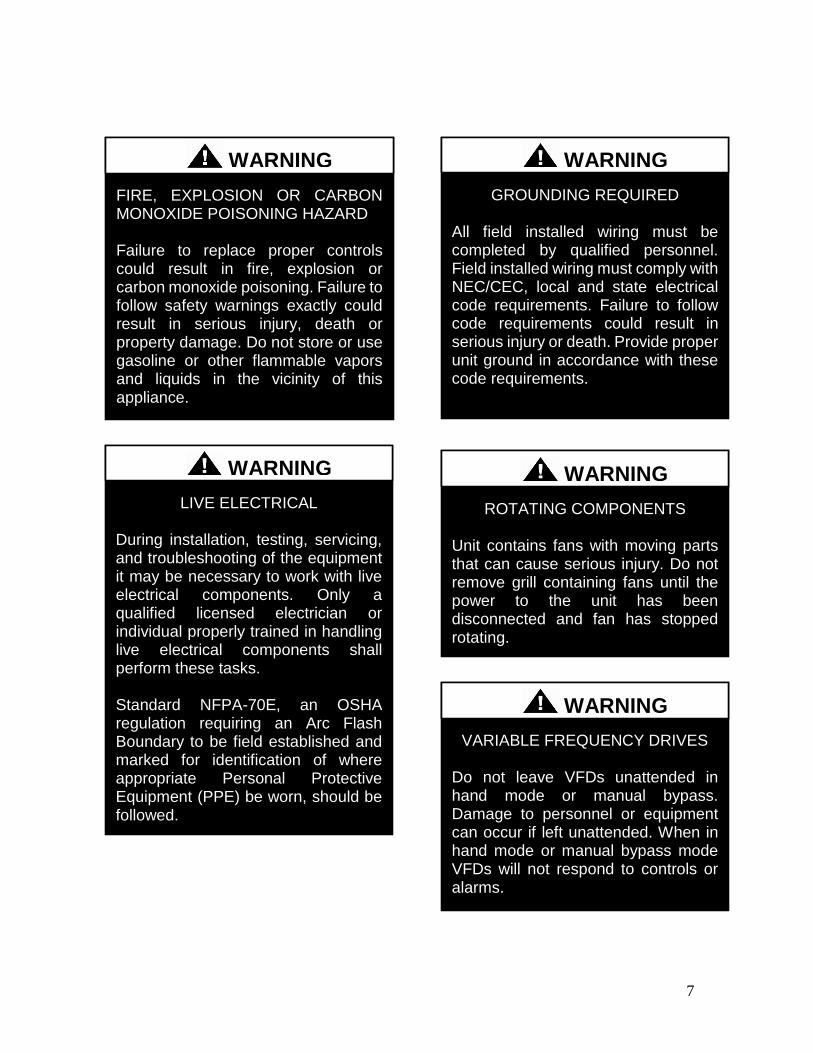
7
ROTATING COMPONENTS Unit contains fans with moving parts that can cause serious injury Do not remove grill containing fans until the power to the unit has been disconnected and fan has stopped rotating
WARNING
LIVE ELECTRICAL During installation testing servicing and troubleshooting of the equipment it may be necessary to work with live electrical components Only a qualified licensed electrician or individual properly trained in handling live electrical components shall perform these tasks Standard NFPA-70E an OSHA regulation requiring an Arc Flash Boundary to be field established and marked for identification of where appropriate Personal Protective Equipment (PPE) be worn should be followed
WARNING
FIRE EXPLOSION OR CARBON MONOXIDE POISONING HAZARD Failure to replace proper controls could result in fire explosion or carbon monoxide poisoning Failure to follow safety warnings exactly could result in serious injury death or property damage Do not store or use gasoline or other flammable vapors and liquids in the vicinity of this appliance
WARNING
GROUNDING REQUIRED All field installed wiring must be completed by qualified personnel Field installed wiring must comply with NECCEC local and state electrical code requirements Failure to follow code requirements could result in serious injury or death Provide proper unit ground in accordance with these code requirements
WARNING
VARIABLE FREQUENCY DRIVES
Do not leave VFDs unattended in hand mode or manual bypass Damage to personnel or equipment can occur if left unattended When in hand mode or manual bypass mode VFDs will not respond to controls or alarms
WARNING
8
LEAK TESTING
Do not use oxygen acetylene or air in place of refrigerant and dry nitrogen for leak testing A violent explosion may result causing injury or death
WARNING
VARIABLE FREQUENCY DRIVES
Electric motor over-current protection and overload protection may be a function of the Variable Frequency Drive to which the motors are wired Never defeat the VFD motor overload feature The overload ampere setting must not exceed 115 of the electric motors FLA rating as shown on the motor nameplate
CAUTION
PVC PIPING
PVC (Polyvinyl Chloride) and CPVC (Chlorinated Polyvinyl Chloride) are vulnerable to attack by certain chemicals Polyolester (POE) oils used with R-410A and other refrigerants even in trace amounts in a PVC or CPVC piping system will result in stress cracking of the piping and fittings and complete piping system failure
CAUTION
3-PHASE ROTATION
Rotation must be checked on all MOTORS AND COMPRESSORS of 3 phase units at startup by a qualified service technician Scroll compressors are directional and can be damaged if rotated in the wrong direction Compressor rotation must be checked using suction and discharge gauges Fan motor rotation should be checked for proper operation Alterations should only be made at the unit power connection
CAUTION
UNIT HANDLING To prevent injury or death lifting equipment capacity shall exceed unit weight by an adequate safety factor Always test-lift unit not more than 24 inches high to verify proper center of gravity lift point to avoid unit damage injury or death
WARNING
DOOR LATCHES
Door compartments containing hazardous voltage or rotating parts are equipped with door latches that allow locks Door latches are shipped with a nut and bolt requiring tooled access If the shipping hardware is not replaced with a pad lock always re-install the nut and bolt after closing the door to maintain tooled access
CAUTION
9
ENCLOSED AREA
Do not work in an enclosed area where refrigerant or nitrogen gases may be leaking A sufficient quantity of vapors may be present and cause
injury or death
WARNING
COMPRESSOR LUBRICANT
Polyolester (POE) and Polyvinylether (PVE) oils are two types of lubricants used in hydrofluorocarbon (HFC) refrigeration systems Refer to the compressor label for the proper compressor lubricant type
CAUTION
COIL CLEANERS
To prevent damage to the unit do not use acidic chemical coil cleaners Do not use alkaline chemical coil cleaners with a pH value greater than 85 after mixing without first using an aluminum corrosion inhibitor in the cleaning solution
CAUTION
COIL CLEANERS
Some chemical coil cleaning compounds are caustic or toxic Use these substances only in accordance with the manufacturerrsquos usage instructions Failure to follow instructions may result in equipment damage injury or death
WARNING
COIL CLEANING
Do not clean DX refrigerant coils with hot water or steam The use of hot water or steam on refrigerant coils will cause high pressure inside the coil tubing and damage to the coil
CAUTION
CONVENIENCE OUTLETS
Factory installed convenience outlets are not intended for use while the unit is operating
WARNING
10
1 Startup and service must be performed by
a Factory Trained Service Technician
2 The unit is for outdoor use only See
General Information section for more
information
3 Every unit has a unique equipment
nameplate with electrical operational
and unit clearance specifications
Always refer to the unit nameplate for
specific ratings unique to the model
purchased
4 READ THE ENTIRE INSTALLATION
OPERATION AND MAINTENANCE
MANUAL OTHER IMPORTANT
SAFETY PRECAUTIONS ARE
PROVIDED THROUGHOUT THIS
MANUAL
5 Keep this manual and all literature
safeguarded near or on the unit
COMPRESSOR CYCLING
5 MINUTE MINIMUM OFF TIME To prevent motor overheating compressors must cycle off for a minimum of 5 minutes
5 MINUTE MINIMUM ON TIME To maintain the proper oil level compressors must cycle on for a minimum of 5 minutes The cycle rate must not exceed 6 starts per hour
WARNING
CF Series Feature String Nomenclature
Model Options Unit Feature Options G
EN
MJ
RE
V
SIZ
E
SE
RIE
S
MN
RE
V
VL
T
A1
A2
A3
A4
A5
1
2A
2B
3A
3B
4
5
6A
6B
6C
7
8A
8B
8C
8D
9
10
11
12
13
14
15
CF A - 015 - B - A - 3 - D C 0 0 K 0 - A 0 - E 0 - C 0 - A N 0 - B - D E 0 0 - 0 0 A 0 E 0 0
0 0 0 0 0 D B
16
17
18
19
20
21
22
11
CF Series Feature String Nomenclature
MODEL OPTIONS Series and Generation
CF
Major Revision
A
Unit Size
002 = 2 ton Capacity
003 = 3 ton Capacity
004 = 4 ton Capacity
005 = 5 ton Capacity
006 = 6 ton Capacity
007 = 7 ton Capacity
009 = 9 ton Capacity
011 = 11 ton Capacity
013 = 13 ton Capacity
015 = 15 ton Capacity
016 = 16 ton Capacity
018 = 18 ton Capacity
020 = 20 ton Capacity
025 = 25 ton Capacity
026 = 26 ton Capacity
030 = 30 ton Capacity
031 = 31 ton Capacity
040 = 40 ton Capacity
050 = 50 ton Capacity
060 = 60 ton Capacity
070 = 70 ton Capacity
Series
A = 2-7 ton units
B = 9-15 ton units
C = 16-25 amp 30 ton units
D = 26 amp 31-70 ton units
Minor Revision
A
Voltage
1 = 230V1Φ60Hz
2 = 230V3Φ60Hz
3 = 460V3Φ60Hz
4 = 575V3Φ60Hz
8 = 208V3Φ60Hz
9 = 208V1Φ60Hz
A1 Compressor Style
0 = Air-Cooled Condenser - No Compressors
(1 Circuit)
A = R-410A Scroll Compressors
B = R-410A Two Step Capacity Scroll Compressors
D = R-410A Variable Capacity Scroll Compressors
E = R-410A Tandem Scroll Compressors
G = R-410A Tandem Variable Capacity Scroll
Compressors
P = Air-Cooled Condenser - No Compressors
(2 Circuits)
Q = Air-Cooled Condenser - No Compressors
(4 Circuits)
A2 Condenser Style
C = Air-Cooled Condenser
J = Air-Source Heat Pump
A3 Configuration
0 = Standard
A4 Coating
0 = Standard
E = Polymer E-Coated Condenser Coil
G = Copper Fin + Stainless Steel Casing - Condenser
Coil
A5 Staging
0 = No Cooling
G = 1 OnOff Refrigeration System
H = 1 Variable Capacity Refrigeration System
J = 2 OnOff Refrigeration Systems
K = 1 Variable Capacity Refrigeration System + 1
OnOff Refrigeration System
L = 2 Variable Capacity Refrigeration System
R = 4 OnOff Refrigeration Systems
T = 2 Variable Capacity Refrigeration Systems + 2
OnOff Refrigeration Systems
U = 4 Variable Capacity Refrigeration Systems
CF Series Feature String Nomenclature
Model Options Unit Feature Options G
EN
MJR
EV
SIZ
E
SE
RIE
S
MN
RE
V
VL
T
A1
A2
A3
A4
A5
1
2A
2B
3A
3B
4
5
6A
6B
6C
7
8A
8B
8C
8D
9
10
11
12
13
14
15
CF A - 015 - B - A - 3 - D C 0 0 K 0 - A 0 - E 0 - C 0 - A N 0 - B - D E 0 0 - 0 0 A 0 E 0 0
0 0 0 0 0 D B
16
17
18
19
20
21
22
12
UNIT FEATURE OPTIONS 1 Unit Orientation
0 = Vertical Condenser Discharge - Standard Access
A = Horizontal Condenser Discharge - Standard
Access
2A Refrigeration Control
0 = Standard
A = 5 Minute Compressor Off Timer + 20 Second
Compressor Stage Delay
C = Adjustable Fan Cycling
D = Adjustable Compressor Lockout
G = Option A + Adjustable Fan Cycling
H = Option A + Adjustable Compressor Lockout
M = Adjustable Fan Cycling + Adjustable
Compressor Lockout
W = Option A + Adjustable Fan Cycling +
Adjustable Compressor Lockout
2B Blank
0 = Standard
3A Refrigeration Options
0 = Standard
A = Hot Gas Bypass Lead Stage [HGB]
B = HGB Lead + HGB Lag
D = Hot Gas Bypass Non-Variable Capacity
Refrigeration Systems [HGBNV]
E = Modulating Hot Gas Reheat [MHGR]
H = HGB + MHGR
J = HGB Lead + HGB Lag + MHGR
L = HGBNV + MHGR
3B Blank
0 = Standard
4 Refrigeration Accessories
0 = Standard
A = Sight Glass
B = Compressor Isolation Valves
C = Options A + B
D = Flooded Condenser 0degF Low Ambient Controls ndash
One Circuit
E = Options A + D
F = Options B + D
G = Options A + B + D
H = Flooded Condenser 0degF Low Ambient Controls-
Two Circuits
J = Options A + H
K = Options B + H
L = Options A + B + H
R = Flooded Condenser 0degF Low Ambient Controls ndash
Four Circuits
S = Options A + R
T = Options B + R
U = Options A + B + R
5 Blank
0 = Standard
6A Unit Disconnect Type
0 = Single Point Power Block
A = Single Point Power Non-Fused Disconnect
6B Disconnect 1 Size
0 = Standard
N = 100 amps
R = 150 amps
V = 250 amps
Z = 400 amps
6C Blank
0 = Standard
CF Series Feature String Nomenclature
Model Options Unit Feature Options
GE
N
MJR
EV
SIZ
E
SE
RIE
S
MN
RE
V
VL
T
A1
A2
A3
A4
A5
1
2A
2B
3A
3B
4
5
6A
6B
6C
7
8A
8B
8
C
8D
9
10
11
12
13
14
15
CF A - 015 - B - 0 - 3 - D C 0 0 K 0 - A 0 - E 0 - C 0 - A N 0 - B - D C 0 0 - 0 0 A 0 E 0 0 0 0 0 0 0 D B
16
17
18
19
20
21
22
13
7 Accessories
0 = Standard
B = Phase amp Brown Out Protection
D = Suction Pressure Transducer on Each
Refrigeration Circuit
E = Compressor Sound Blanket
L = Options B + D
M = Options B + E
Q = Options D + E
1 = Options B + D + E
8A Control Sequence
A = Terminal Block for Thermostat w Isolation
Relays
D = VAV Unit Controller - VAV Cool + CAV Heat
E = CAV Unit Controller
F = Makeup Air Unit Controller - CAV Cool + CAV
Heat
H = Constant Volume HP Unit Controller - CAV
Cool + CAV Heat
J = Makeup Air HP Unit Controller - CAV Cool +
CAV Heat
N = Field Installed DDC Controls by Others with
Isolation Relays
8B Control Suppliers
0 = Standard
E = Orion VCC-X (Main Controller in Air Handling
Unit)
H = AAON Touchscreen Controller (Main Controller
in Air Handling Unit)
8C Control Supplier Options
0 = Standard
8D BMS Connection amp Diagnostics
0 = Standard
9 Blank
0 = Standard
10 Blank
0 = Standard
11 Maintenance Accessories
0 = Standard
A = Factory Wired 115VAC Convenience Outlet
B = Field Wired 115VAC Convenience Outlet
C = Service Lights
E = Remote Unit StartStop Terminals
F = Options A + C
H = Options A + E
J = Options B + C
L = Options B + E
N = Options C + E
R = Options A + C + E
U = Options B + C + E
12 Code Options
0 = Standard ETL USA Listing
B = ETL USA + Canada Listing
13 Air-Cooled Condenser Accessories
0 = Standard
A = Condenser Coil Guard
C = ECM Condenser Fan Head Pressure Control
E = VFD Condenser Fan Head Pressure Control
G = Options A + C
J = Options A + E
N = ECM Condenser Fan Head Pressure Control +
Low Sound Condenser Fan
S = Options A + N
14 Blank
0 = Standard
15 Blank
0 = Standard
16 Electrical Options
0 = Standard
17 Shipping Options
0 = Standard
A = Crating
B = Export Crating
CF Series Feature String Nomenclature
Model Options Unit Feature Options G
EN
MJR
EV
SIZ
E
SE
RIE
S
MN
RE
V
VL
T
A1
A2
A3
A4
A5
1
2A
2B
3A
3B
4
5
6A
6B
6C
7
8A
8B
8C
8D
9
10
11
12
13
14
15
CF A - 015 - B - A - 3 - D C 0 0 K 0 - A 0 - E 0 - C 0 - A N 0 - B - D E 0 0 - 0 0 A 0 E 0 0
0 0 0 0 0 D B 1
6
17
18
19
20
21
22
14
18 Blank
0 = Standard
19 Blank
0 = Standard
20 Cabinet Material
0 = Galvanized Steel Cabinet
21 Warranty
0 = Standard
D = Compressor Warranty - Years 2-5
22 Type
B = Premium AAON Gray Paint Exterior
E = Premium AAON Gray Paint Ext + Shrink Wrap
X = SPA + Premium AAON Gray Paint Exterior
1 = SPA + Premium AAON Gray Paint Exterior +
Shrink Wrap
15
General Information
AAON CF Series air-cooled condensers and
condensing units have been designed for
outdoor use only They are factory
assembled wired charged and run-tested
Codes and Ordinances
CF Series units have been tested and
certified by ETL in accordance with UL
Safety Standard 1995CSA C222 No 236
System should be sized in accordance with
the American Society of Heating
Refrigeration and Air Conditioning
Engineers Handbook
Installation of CF Series units must conform
to the ICC standards of the International
Mechanical Code the International Building
Code and local building plumbing and
electrical codes All appliances must be
electrically grounded in accordance with
local codes or in the absence of local codes
the current National Electric Code
ANSINFPA 70 or the current Canadian
Electrical Code CSA C221
Receiving Unit
When received the unit should be checked
for damage that might have occurred in
transit If damage is found it should be noted
on the carrierrsquos freight bill A request for
inspection by carrierrsquos agent should be made
in writing at once Nameplate should be
checked to ensure the correct model sizes and
voltages have been received to match the job
requirements
If repairs must be made to damaged goods
then the factory should be notified before any
repair action is taken in order to protect the
warranty Certain equipment alteration
repair and manipulation of equipment
without the manufacturerrsquos consent may void
the product warranty Contact AAON
Technical Support for assistance with
handling damaged goods repairs and freight
claims (918) 382-6450
SHARP EDGES
Coils and sheet metal surfaces present sharp edges and care must be taken when working with equipment
WARNING
QUALIFIED INSTALLER
Improper installation adjustment alteration service or maintenance can cause property damage personal injury or loss of life Installation and service must be performed by a Factory Trained Service Technician
WARNING
Failure to observe the following instructions will result in premature failure of your system and possible voiding of the warranty
WARNING
16
Storage
If installation will not occur immediately
following delivery store equipment in a dry
protected area away from construction traffic
and in the proper orientation as marked on the
packaging with all internal packaging in
place Secure all loose-shipped items
Failure to observe the following instructions
will result in premature failure of your
system and possible voiding of the warranty
Never turn off the main power supply to the
unit except for complete shutdown When
power is cut off from the unit any
compressors using crankcase heaters cannot
prevent refrigerant migration This means the
compressor will cool down and liquid
refrigerant may accumulate in the
compressor The compressor is designed to
pump refrigerant gas and damage may occur
if liquid enters the compressor when power is
restored
Before unit operation the main power switch
must be turned on for at least twenty-four
hours for units with compressor crankcase
heaters This will give the crankcase heater
time to clear any liquid accumulation out of
the compressor before it is required to run
Always control the system from the control
panel never at the main power supply (except
for emergency or for complete shutdown of
the system)
CLEAN AIR ACT
The Clean Air Act of 1990 bans the intentional venting of refrigerant as of July 1 1992 Approved methods of recovery recycling or reclaiming must be followed
CAUTION
CRANKCASE HEATER OPERATION
Units are equipped with compressor crankcase heaters which should be energized at least 24 hours prior to cooling operation to clear any liquid refrigerant from the compressors
CAUTION
3-PHASE ROTATION
Rotation must be checked on all MOTORS AND COMPRESSORS of three phase units All motors to include and not be limited to pump motors and condenser fan motors should all be checked by a qualified service technician at startup and any wiring alteration should only be made at the unit power connection
CAUTION
17
The standard compressors must be on a
minimum of 5 minutes and off for a minimum
of 5 minutes The cycle rate must be no more
than 6 starts per hour
The variable capacity compressors must be
on a minimum of 3 minutes and off for a
minimum of 3 minutes The cycle rate must
be no more than 6 starts per hour
The compressor life will be seriously
shortened by reduced lubrication and the
pumping of excessive amounts of liquid oil
and liquid refrigerant
Wiring Diagrams
A complete set of unit specific wiring
diagram in point-to-point form is laminated
in plastic and located inside the control
compartment door
General Maintenance
When the initial startup is made and on a
periodic schedule during operation it is
necessary to perform routine service checks
on the performance of the condensing unit
This includes reading and recording suction
pressures and checking for normal sub-
cooling and superheat
COMPRESSOR ROTATION
Scroll compressors are directional and will be damaged by operation in the wrong direction Low pressure switches on compressors have been disconnected after factory testing Rotation should be checked by a qualified service technician at startup using suction and discharge pressure gauges and any wiring alteration should only be made at the unit power connection
COMPRESSOR CYCLING
5 MINUTE MINIMUM OFF TIME To prevent motor overheating compressors must cycle off for a minimum of 5 minutes
5 MINUTE MINIMUM ON TIME To maintain the proper oil level compressors must cycle on for a minimum of 5 minutes The cycle rate must not exceed 6 starts per hour
WARNING
CAUTION
18
Installation
Forklifting the Unit
CF Series condensing unit sizes 2-25 amp 30
tons can be lifted using a forklift 2-7 ton
units must have forks at least 48rdquo in length
9-25 amp 30 ton units must have forks 72rdquo in
length or the forks must have 72rdquo fork
extensions Standard units can be lifted from
all sides except the condenser coil side CF
Series condensing unit sizes 26 amp 31-70 tons
cannot be lifted using a forklift They can be
lifted as shown in Figure 3
Forks must be perpendicular to the unit and
they must be in far enough that the back of
the forks are no more than 6rdquo away from the
edge of the unit
Figure 1 - Forklifting a CF Series A Cabinet
Figure 2 - Forklifting a CF Series B and C
Cabinet
FORKLIFTING 2-7 TON UNITS
Forks or Fork Extensions must be at least 48rdquo in length
CAUTION
FORKLIFTING 9-25 amp 30 TON UNITS
Forks or Fork Extensions must be at least 72rdquo in length
CAUTION
19
Lifting the Unit
If cables or chains are used to hoist the unit
they must be the same length Minimum
cable length is 99rdquo for CF Series 9-70 ton
units CF Series 2-7 ton units do not include
factory installed lifting lugs and should be
lifted by forklift only Care should be taken
to prevent damage to the cabinet coils and
condenser fans
Before lifting unit be sure that all shipping
material has been removed from unit Secure
hooks and cables at all lifting points lugs
provided on the unit
Figure 3 ndash Lifting Details and Orientation of
a CF Series 9-70 ton Condensing Unit
Locating the Unit
The CF Series condenser and condensing unit
is designed for outdoor applications and
mounting at ground level or on a rooftop It
must be placed on a level and solid
foundation that has been prepared to support
its weight When installed at ground level a
one-piece concrete slab should be used with
footings that extend below the frost line Also
with ground level installation care must be
taken to protect the coil fins from damage due
to vandalism or other causes
The first clearance table below gives the
clearance values for proper unit operation
The second clearance table gives the
clearance necessary for removing the coil
without disassembling a large part of the
condensing unit For ease of removing the
condenser coil use the second table
clearances for the right hand side of the unit
Table 1 ndashClearances for Proper Operation
Location Unit Size
2-7 tons 9-70 tons
Front -
(Controls
Side)
Unobstructed 36rdquo
Left Side 6rdquo 30rdquo
Right Side 6rdquo 36rdquo
Top 3rdquo Unobstructed
Back 18rdquo 6rdquo
Table 2 ndash Clearances for Coil Pull
Unit Size Right Hand Side
2-7 tons 42rdquo
9-15 tons 42rdquo
16-25 amp 30 tons 54rdquo
26 amp 31-70 tons 66rdquo
Figure 4 - Orientation of Series 2-7 ton
Condensing Unit
20
The placement relative to the building air
intakes and other structures must be carefully
selected Airflow to and from the condenser
or condensing unit must not be restricted to
prevent a decrease in performance and
efficiency
The installation position for 9-70 ton units
must provide at least 30rdquo of left and right side
clearance for proper airflow to the condenser
coils When units are mounted adjacent to
each other the minimum right and left side
clearance required between the units is 60rdquo or
5 feet Similarly when 2-7 ton units are
mounted adjacent to each other the minimum
clearance required between the back side of
the units is 36rdquo or 3 feet
Units should not be installed in an enclosure
or pit that is deeper than the height of the unit
When recessed installation is necessary the
clearance to maintain proper airflow is at
least 5 feet (3 feet for 2-7tons)
CF Series condensers and condensing units
that have a vertical air discharge must have
no obstruction above the equipment Do not
place the unit under an overhang CF Series
condensers and condensing units that have a
horizontal discharge must have no
obstruction in front of the unit
For proper unit operation the immediate area
around condenser must remain free of debris
that may be drawn in and obstruct airflow in
the condensing section
Consideration must be given to obstruction
caused by snow accumulation when placing
the unit
Mounting Isolation
For roof mounted applications or anytime
vibration transmission is a factor vibration
isolators may be used
Access Doors
Access doors are provided to the compressor
and electrical compartment
Standard Evacuation Instructions
Proper system evacuation is critical to
remove moisture and non-condensables from
the system before charging the system with
refrigerant A newly installed AAON
condensing unit has already been evacuated
and charged with some refrigerant at the
factory When evacuating a new system
keep the condensing unit service valves
closed and evacuate the suction and liquid
lines and the air handling unit If the entire
system must be evacuated use the following
procedure to ensure the entire system is
pulled into a good vacuum
1 System evacuation should be
performed anytime a system is open to
atmospheric pressure The POE oils
used with R-410A are extremely
hydroscopic in nature and immediately
begin pulling in moisture once the
system is opened to the atmosphere
2 Before starting to evacuate the
system you MUST ensure that there are
no leaks by pressurizing the system with
PVC PIPING
PVC (Polyvinyl Chloride) and CPVC (Chlorinated Polyvinyl Chloride) are vulnerable to attack by certain chemicals Polyolester (POE) oils used with R-410A and other refrigerants even in trace amounts in a PVC or CPVC piping system will result in stress cracking of the piping and fittings and complete piping system failure
CAUTION
21
400 psig of dry nitrogen and verifying no
pressure loss after one hour
3 Four valve manifold gauge sets are
more effective than standard manifold
gauge sets due to the extra hose port in
combination with a 38rsquorsquo evacuation
port The larger diameter evacuation port
will expedite system evacuation
4 The manifold set should be connected
to the condensing unit with one hose on
the suction line service valve one hose
on the liquid line service valve and if an
extra Schrader valve is field installed on
the suction line connect a third hose (not
shown) The vacuum pump should be
connected to the manifold set using a
38rdquo vacuum rated hose Figure 5 shows
two circuits Both circuits must be
evacuated separately
Figure 5 ndash CU evacuation connections
5 An accurate micron gauge must be
used and checked by pulling a vacuum
on the gauge by itself and verify a rapid
drop to less than 100 microns within a
few minutes
6 The micron gauge should not be
attached to the system until the gauge
manifold is reading 28rsquorsquo of vacuum to
ensure the micron gauge does not see
pressure and is thus damaged MICRON
GAUGES WILL BE DAMAGED BY
PRESSURE
7 It is a good practice to replace the
vacuum pump oil after one hour of the
evacuation process The oil can be
broken down in the pump in the initial
first hour causing system evacuation to
take longer than it should
8 The minimum micron level required
by AAON is 350 microns for systems
using POE oils
9 The system should then be isolated
and the pump turned off to check for
vacuum rise due to leaks or moisture in
the system The micron gauge should
not rise above 500 microns after 30
minutes of wait time
Low Ambient amp Modulating Reheat
System Evacuation Instructions
Proper system evacuation is critical to
remove moisture and non-condensables from
the system before charging the system with
refrigerant Systems with low ambient
flooded condenser option require the
following procedure to ensure the entire
system is pulled into a good vacuum
1 System evacuation should be
performed anytime a system is open to
atmospheric pressure The POE oils
used with R-410A are extremely
hydroscopic in nature and immediately
begin pulling in moisture once the
system is opened to the atmosphere
2 Open the reheat valve to 50 when
evacuating
3 Before starting to evacuate the
system you MUST ensure that there are
no leaks by pressurizing the system with
22
400 psig of dry nitrogen and verifying no
pressure loss after one hour
4 Four valve manifold gauge sets are
more effective than standard manifold
gauge sets due to the extra hose port in
combination with a 38rsquorsquo evacuation
port The larger diameter evacuation port
will expedite system evacuation
5 The manifold set should be connected
to the condensing unit with one hose on
the suction line service valve one hose
on the liquid line service valve and a
third hose on the reheat line service
valve The vacuum pump should be
connected to the manifold set using a
38rdquo vacuum rated hose Figure 6 shows
two circuits The first circuit has a
reheat line the second circuit is just the
suction and liquid line Both circuits
must be evacuated separately
Figure 6 ndash CU evacuation connections
6 FAILURE to connect to the liquid
line service valve will result in the
receiver tank not being fully evacuated
and most likely lead to non-
condensables in the system
7 An accurate micron gauge must be
used and checked by pulling a vacuum
on the gauge by itself and verify a rapid
drop to less than 100 microns within a
few minutes
8 The micron gauge should not be
attached to the system until the gauge
manifold is reading 28rsquorsquo of vacuum to
ensure the micron gauge does not see
pressure and is thus damaged MICRON
GAUGES WILL BE DAMAGED BY
PRESSURE
9 It is a good practice to replace the
vacuum pump oil after one hour of the
evacuation process The oil can be
broken down in the pump in the initial
first hour causing system evacuation to
take longer than it should
10 The minimum micron level required
by AAON is 350 microns for systems
using POE oils
11 The system should then be isolated
and the pump turned off to check for
vacuum rise due to leaks or moisture in
the system The micron gauge should
not rise above 500 microns after 30
minutes of wait time
Adjusting Refrigerant Charge
All AAON CF Series condensers and
condensing units are shipped with a factory
holding charge The factory charge is
different depending on the unit size and
system (heat pump modulating hot gas
reheat LAC) The factory charge per circuit
is shown on the unit nameplate Adjusting the
charge of the system will be required during
installation
23
Adjusting the charge of a system in the field
must be based on determination of liquid sub-
cooling and evaporator superheat On a
system with a thermostatic expansion valve
liquid sub-cooling is more representative of
the charge than evaporator superheat but both
measurements must be taken
Before Charging
Refer to the Unit Nameplate to determine
which refrigerant must be used to charge the
system
Unit being charged must be at or near full
load conditions before adjusting the charge
Units equipped with hot gas bypass must
have the hot gas bypass valve closed to get
the proper charge
Units equipped with hot gas reheat must be
charged with the hot gas valve closed while
the unit is in cooling mode After charging
unit should be operated in reheat
(dehumidification) mode to check for correct
operation
Units equipped with heat pump options
should be charged in cooling mode to get the
proper charge After charging unit should be
operated in heating mode to check for correct
charge Charge may need to be adjusted for
heating mode If adjustments are made in the
heating mode cooling mode must be rerun to
verify proper operation
After adding or removing charge the system
must be allowed to stabilize typically 10-15
minutes before making any other
adjustments
The type of unit and options determine the
ranges for liquid sub-cooling and evaporator
superheat Refer to Table 3 when determining
the proper sub-cooling
For units equipped with low ambient (0degF)
option see the special charging instructions at
the end of this section
Checking Liquid Sub-cooling
Measure the temperature of the liquid line as
it leaves the condenser coil
Read the gauge pressure at the liquid line
close to the point where the temperature was
taken You must use liquid line pressure as it
will vary from discharge pressure due to
condenser coil pressure drop
Convert the pressure obtained to a saturated
temperature using the appropriate refrigerant
temperature-pressure chart
COMPRESSOR LUBRICANT
Polyolester (POE) and Polyvinylether (PVE) oils are two types of lubricants used in hydrofluorocarbon (HFC) refrigeration systems Refer to the compressor label for the proper compressor lubricant type
CAUTION
CLEAN AIR ACT
The Clean Air Act of 1990 bans the intentional venting of refrigerant (CFCrsquos and HCFCrsquos) as of July 1 1992 Approved methods of recovery recycling or reclaiming must be followed Fines andor incarceration may be levied for non-compliance
CAUTION
24
Subtract the measured liquid line temperature
from the saturated temperature to determine
the liquid sub-cooling
Compare calculated sub-cooling to Table 3
for the appropriate unit type and options
Table 3 - Acceptable Refrigeration Circuit
Values
Cooling
Mode
Liquid Sub-
Cooling
Values
Cooling Only Unit4 8-15degF
Cooling Only Unit with Hot
Gas Reheat14 5-15degF
Heat PumpUnit24 2-4degF
Heat Pump Unit with Hot
Gas Reheat34 2-6degF
Cooling Only Unit with
LAC4 8-15degF
Cooling Only Unit with Hot
Gas Reheat amp LAC4 8-15degF
Notes 1 Must be charged with the hot gas valve
closed After charging unit should be
operated in reheat (dehumidification) mode
to check for correct operation
2 The sub-cooling value in this table is for the
unit running in cooling mode of operation
After charging unit should be operated in
heating mode to check for correct operation
3 The sub-cooling value in this table is for the
unit running in cooling mode of operation
and the hot gas valve closed After charging
unit should be operated in reheat
(dehumidification) mode to check for correct
operation and then in heating mode to check
for correct operation
4 Sub-cooling must be increased by 1degF per 10
feet of vertical liquid line rise for R-410A
(AHU above CU) For example a cooling
only unit with hot gas reheat and a vertical
liquid drop can charge to a sub-cooling value
of 5-15degF but a cooling only unit with hot
gas reheat and a vertical liquid rise of 30 ft
must charge to a sub-cooling value of at least
8-15degF DO NOT OVERCHARGE
Refrigerant overcharging leads to excess
refrigerant in the condenser coils resulting in
elevated compressor discharge pressure
Checking Evaporator Superheat
Measure the temperature of the suction line
close to the compressor
Read gauge pressure at the suction line close
to the compressor
Convert the pressure obtained to a saturated
temperature using the appropriate refrigerant
temperature-pressure chart
Subtract the saturated temperature from the
measured suction line temperature to
determine the evaporator superheat
For refrigeration systems with tandem
compressors it is critical that the suction
superheat setpoint on the TXV is set with one
compressor running The suction superheat
should be 10-13degF with one compressor
running The suction superheat will increase
with both compressors in a tandem running
Inadequate suction superheat can allow liquid
refrigerant to return to the compressors which
will wash the oil out of the compressor Lack
of oil lubrication will destroy a compressor
Liquid sub-cooling should be measured with
both compressors in a refrigeration system
running
Compare calculated superheat to the
acceptable cooling mode superheat values of
8-15degF for all system types Superheat will
increase with long suction line runs
25
Adjusting Sub-cooling and Superheat
Temperatures
The system is overcharged if the sub-cooling
temperature is too high compared to Table 3
and the evaporator is fully loaded (low loads
on the evaporator result in increased sub-
cooling) and the evaporator superheat is
within the temperature range of 8-15degF (high
superheat results in increased sub-cooling)
Correct an overcharged system by reducing
the amount of refrigerant in the system to
lower the sub-cooling
The system is undercharged if the superheat
is too high and the sub-cooling is too low
Correct an undercharged system by adding
refrigerant to the system to reduce superheat
and raise sub-cooling
If the sub-cooling is correct and the superheat
is too high the TXV may need adjustment to
correct the superheat
DO NOT OVERCHARGE Refrigerant overcharging leads to excess refrigerant in the condenser coils resulting in elevated compressor discharge pressure
CAUTION
EXPANSION VALVE ADJUSTMENT
Thermal expansion valves must be adjusted to approximately 8-15degF of suction superheat Failure to have sufficient superheat will damage the compressor and void the warranty
CAUTION
26
Special Low Ambient Option Charging
Instructions
For units equipped with low ambient
refrigerant flood back option being charged
in the summer when the ambient
temperature is warm
If the ambient is above 70degF charge to
approximately 1-2degF of sub-cooling
measured at the inlet to the expansion valve
Once enough charge has been added to get
the evaporator superheat and sub-cooling
values to the correct setting more charge
must be added Use Table 4 to find the
additional charge amount required for the
system when running in cold ambient
conditions
Table 4 ndash Charge to Flood Condenser Coil
for Ambient Above 70degF
CF Size of
circuits
Per Circuit
Charge (lbs)
CF 2 3 1 49
CF 4 5 6 7 1 92
CF 9 11 2 91
CF 13 15 2 121
CF 16 18 2 131
CF 20 25 30 2 175
CF 26 31 40 2 180
4 91
CF 50 60 70 2 438
4 221
For units equipped with low ambient
refrigerant flood back option being charged
in the winter when the ambient
temperature is cold
1 If the ambient is below 70degF charge
to approximately 1-2degF of sub-cooling
measured at the inlet to the expansion
valve Once enough charge has been
added to get the evaporator superheat
and sub-cooling values to the correct
setting more charge may need to be
added If the ambient temperature is 0degF
no more charge is required Ambient
temperatures above 0degF will require a
percentage of the per circuit charge
values from Table 4 Using your
ambient temperature find the
percentage value from Table 5 and
multiply the Per Circuit Charge value
from Table 4 and the value to
determine the additional charge amount
Table 5 ndash Charge to Flood Condenser
Coil for Ambient Below 70degF
Condenser
Ambient
Temperature ˚F
Percentage
Per Circuit
Charge from
Table 4
60 60
50 37
40 24
30 15
20 8
0 0
2 The unit should be checked for proper
operation once the ambient temperature
is above 80degF
Example A CF size 31 with tandem
compressors where the ambient
temperature is 40degF
From Table 4 ndash 18 lbs refrigerant charge
per circuit (tandem compressors would
have 2 circuits in this size of CF)
From Table 5 ndash 24 of Table 4 charge
Additional charge needed for a unit with
low ambient flooded condenser controls
= 18 lbs 024 = 432 lbs additional
refrigerant charge per circuit
27
Low Ambient Operation
During low ambient temperatures the vapor
refrigerant will migrate to the cold part of the
system and condense into liquid All CF
Series compressors are provided with factory
installed crankcase heaters to help prevent
liquid refrigerant from slugging the
compressors during startup in low ambient
conditions The condenser or condensing unit
must have continuous power 24 hours prior
to startup This ensures the compressor will
receive sufficient refrigerant vapor at startup
Standard units can operate down to 55degF
ambient temperature
AAON condenser fan head pressure control
units can operate down to 35degF ambient
temperature Three different condenser fan
head pressure control options available are
adjustable fan cycling ECM condenser fan
or VFD controlled condenser fans See
detailed information following
The AAON low ambient (condenser flood-
back) system is used to operate a refrigerant
system down to 0degF outside air temperature
See detailed information following
Fan Cycling Low Ambient
Adjustable fan cycling is a low ambient head
pressure control option that cycles the
condenser fans to maintain refrigerant circuit
head pressures at acceptable levels during
cooling operation The head pressure set
point (100-470 psi) and pressure differential
(35-200 psi) can be field adjusted using a
flathead screwdriver For example if the
head pressure is set to 300psi and the
differential is set to 100psi then fans will cut
in at 300psi and cut out at 200psi Fan
cycling and variable speed condenser fan
head pressure control options allow
mechanical cooling with ambient
temperatures down to 35degF
Figure 7 - Adjustable Fan Cycling Switch
Variable Speed Low Ambient
Variable speed condenser fan head pressure
control is a low ambient head pressure
control option that sends a variable signal in
relation to the refrigerant circuit head
pressure of the system to an electronically
commutated motor (ECM) or VFD The
motor either speeds up or slows down air
flow accordingly in order to maintain
constant head pressure Fan cycling and
variable speed condenser fan head pressure
control options allow mechanical cooling
with ambient temperatures down to 35degF
Flooded Condenser Low Ambient
Flooded condenser low ambient control
maintains normal head pressure during
periods of low ambient When the ambient
temperature drops the condensing
temperature and therefore pressure drops
Without ambient control the system would
shut down on low discharge pressure The
flooded condenser method of low ambient
control fills the condenser coil with liquid
refrigerant decreasing the heat transfer
capacity of the coil which allows the coil to
operate at an acceptable discharge pressure
28
The condenser coil will not be flooded during
summer ambient temperatures so a receiver
is included to store the additional liquid
refrigerant required to flood the condenser
coil in low ambient The receiver is factory-
sized to contain all of the flooded volume
Without a receiver there would be high head
pressures during higher ambient conditions
The low ambient system maintains normal
head pressure during periods of low ambient
by restricting liquid flow from the condenser
to the receiver and at the same time
bypassing hot gas around the condenser to the
inlet of the receiver This reduces liquid
refrigerant flow from the condenser reducing
its effective surface area which in turn
increases the condensing pressure At the
same time the bypassed hot gas raises liquid
pressure in the receiver allowing the system
to operate properly CF Series condensers
and condensing units use an LAC valve for
low ambient operation
LAC Valve
The Low Ambient Control (LAC) valve is a
non-adjustable three way valve that
modulates to maintain receiver pressure As
the receiver pressure drops below the valve
setting (295 psig for R-410A) the valve
modulates to bypass discharge gas around the
condenser The discharge gas warms the
liquid in the receiver and raises the pressure
to the valve setting The following schematic
shows an example system using the LAC
valve
Figure 8 ndash LAC Piping Example
29
Refrigerant Piping
(See back of the manual for refrigerant piping
diagrams)
General
Piping from the condensing unit to the air
handler is the responsibility of the installing
contractor
Use only clean type ldquoACRrdquo copper tubing
that has been joined with high temperature
brazing alloy
The pipe or line sizes must be selected to
meet the actual installation conditions and
NOT simply based on the connection sizes at
the condensing unit or air handler
All CF Series condensing units are provided
with in-line shutoff valves on both the liquid
and suction lines These should remain closed
until the system is ready for start-up after
installation
Piping should conform to generally accepted
practices and codes
Care must be taken not to cross the circuits
on multiple circuit systems
Upon completion of piping connection the
interconnecting piping and air handler MUST
BE evacuated to 500 microns or less leak
checked and charged with refrigerant
Determining Refrigerant Line Size
The piping between the condenser and low
side must ensure
1 Minimum pressure drop and
2 Continuous oil return and
3 Prevention of liquid refrigerant slugging
or carryover
Minimizing the refrigerant line size is
favorable from an economic perspective
reducing installation costs and reducing the
potential for leakage However as pipe
diameters decrease pressure drop increases
Excessive suction line pressure drop causes
loss of compressor capacity and increased
power usage resulting in reduced system
efficiency Excessive pressure drops in the
liquid line can cause the liquid refrigerant to
flash resulting in faulty TXV operation and
improper system performance In order to
operate efficiently and cost effectively while
avoiding malfunction refrigeration systems
must be designed to minimize both cost and
pressure loss
REFRIGERANT PIPING
Line sizes must be selected to meet actual installation conditions not simply based on the connection sizes at the condensing unit or air handling unit
CAUTION
REFRIGERANT PIPING
This section is for information only and is not intended to provide all details required by the designer or installer of the refrigerant piping between the condenser or condensing unit and the air handling unit AAON Inc is not responsible for interconnecting refrigerant piping Consult ASHRAE Handbook ndash Refrigeration and ASME Standards
CAUTION
30
Equivalent Line Length
All line lengths discussed in this manual
unless specifically stated otherwise are
Equivalent Line Lengths The frictional
pressure drop through valves fittings and
accessories is determined by establishing the
equivalent length of straight pipe of the same
diameter Always use equivalent line
lengths when calculating pressure drop
Special piping provisions must be taken
when lines are up vertical risers or in
excessively long line runs AAON does not
recommend running underground
refrigerant lines
Liquid Line
When sizing the liquid line it is important to
minimize the refrigerant charge to reduce
installation costs and improve system
reliability This can be achieved by
minimizing the liquid line diameter
However reducing the pipe diameter will
increase the velocity of the liquid refrigerant
which increases the frictional pressure drop
in the liquid line and causes other
undesirable effects such as noise
Maintaining the pressure in the liquid line is
critical to ensuring sufficient saturation
temperature avoiding flashing upstream of
the TXV and maintaining system efficiency
Pressure losses through the liquid line due to
frictional contact installed accessories and
vertical risers are inevitable Maintaining
adequate sub-cooling at the condenser to
overcome these losses is the only method to
ensure that liquid refrigerant reaches the
TXV
Liquid refrigerant traveling upwards in a riser
loses head pressure If the evaporator is
below the condenser with the liquid line
flowing down the gravitational force will
increase the pressure of the liquid refrigerant
This will allow the refrigerant to withstand
greater frictional losses without the
occurrence of flashing prior to the TXV
A moisture-indicating sight glass may be
field installed in the liquid line to indicate the
occurrence of premature flashing or moisture
in the line The sight glass should not be used
to determine if the system is properly
charged Use temperature and pressure
measurements to determine liquid sub-
cooling not the sight glass
Liquid Line Routing
Care should be taken with vertical risers
When the system is shut down gravity will
pull liquid down the vertical column and
back to the condenser when it is below the
evaporator This could potentially result in
compressor flooding A check valve can be
installed in the liquid line where the liquid
column rises above the condenser to prevent
this The liquid line is typically pitched along
with the suction line or hot gas line to
minimize the complexity of the
configuration
Liquid Line Insulation
In cooling only systems when the liquid line
is routed through regions where temperature
losses are expected no insulation is required
as this may provide additional sub-cooling to
the refrigerant When routing the liquid line
through high temperature areas insulation of
the line is appropriate to avoid loss of sub-
cooling through heat gain
In heat pump systems when the liquid line is
routed through regions where temperature
losses are expected (all lines exposed to
outside air conditions) insulate with a
minimum 1 inch thick Armaflex insulation
as this will prevent capacity loss during
heating mode of operation
31
Liquid Line Guidelines
In order to ensure liquid at the TXV the sum
of frictional losses and pressure loss due to
vertical rise must not exceed available sub-
cooling A commonly used guideline to
consider is a system design with pressure
losses due to friction through the line not to
exceed a corresponding 1-2degF change in
saturation temperature An additional
recommendation is that the sum of frictional
losses (including valve losses filter drier
losses other accessories and line losses) and
pressure loss due to vertical rise should not
exceed 8degF if the available sub-cooling is
10degF
If the velocity of refrigerant in the liquid line
is too great it could cause excessive noise or
piping erosion The recommended maximum
velocities for liquid lines are 100 fpm from
the condenser to a receiver to discourage
fluid backup and 500 fpm from receiver tank
to the evaporator (300 fpm if the line includes
an electric valve to minimize valve induced
liquid hammer)
Liquid Line Accessories
Liquid line shut off valves and filter driers are
factory provided The total length equivalent
of pressure losses through valves elbows and
fittings must be considered when adding
additional components in the field It is a
good practice to utilize the fewest elbows that
will allow the mating units to be successfully
joined
A liquid line receiver is factory installed on
units with modulating hot gas reheat units
with low ambient control flooded condenser
and units with heat pump
Suction Line
The suction line is more critical than the
liquid line from a design and construction
standpoint More care must be taken to
ensure that adequate velocity is achieved to
return oil to the compressor at minimum
loading conditions However reducing the
piping diameter to increase the velocity at
minimal load can result in excessive pressure
losses capacity reduction and noise at full
load
Suction Line Routing
For cooling only systems pitch the suction
line in the direction of flow (about 1 inch per
20 feet of length) to maintain oil flow
towards the compressor and keep it from
flooding back into the evaporator
For heat pump systems do not pitch lines
since they will be flowing in one direction in
cooling mode and the opposite direction in
heating mode
Crankcase heaters are provided to keep any
condensed refrigerant that collects in the
compressor from causing damage or wear
Make sure to provide support to maintain
suction line positioning and insulate
completely between the evaporator and
condensing unit
It is important to consider part load operation
when sizing suction lines At minimum
capacity refrigerant velocity may not be
adequate to return oil up the vertical riser
Decreasing the diameter of the vertical riser
will increase the velocity but also the
frictional loss
For difficult line routing applications a
double suction riser can be applied to the
situation of part load operation with a suction
riser A double suction riser is designed to
return oil at minimum load while not
incurring excessive frictional losses at full
load A double suction riser consists of a
small diameter riser in parallel with a larger
diameter riser and a trap at the base of the
large riser At minimum capacity refrigerant
velocity is not sufficient to carry oil up both
32
risers and it collects in the trap effectively
closing off the larger diameter riser and
diverting refrigerant up the small riser where
velocity of the refrigerant is sufficient to
maintain oil flow At full load the mass flow
clears the trap of oil and refrigerant is carried
through both risers The smaller diameter
pipe should be sized to return oil at minimum
load while the larger diameter pipe should be
sized so that flow through both pipes
provides acceptable pressure drop at full
load
Figure 9 - Double Suction Riser
Construction
A double riser can also be used for heat pump
operation The specific volume (ft3lb) of
refrigerant at the discharge temperature and
pressure (heating mode line conditions) is
significantly lower than the specific volume
at the suction temperature and pressure
(cooling mode line conditions) To
compound the issue the capacity in heating
mode is lower than the capacity in cooling
mode The discharge velocity in the riser
during heating mode is much lower than the
suction velocity during cooling mode Often
a double riser is necessary to get acceptable
velocities for the discharge mode and
acceptable velocities for the suction mode In
the example diagrams (See Figure 10 amp
Figure 11) the cooling mode will use both
lines and the heating mode will use only one
Suction Line Traps
Include a trap immediately after the
evaporator coil outlet to protect the TXV bulb
from liquid refrigerant
Include traps every 20 feet in vertical suction
riser sections for cooling only systems and
every 12 feet for heat pump systems
Suction Line Insulation
The entire suction line should be insulated
with a minimum 1 inch thick Armaflex
insulation This prevents condensation from
forming on the line and reduces any potential
loss in capacity associated with heat gain
placing additional load on the system This
line should still be insulated in heat pump
systems even though it acts as both a
discharge and suction line
Suction Line Guidelines
For proper performance suction line
velocities less than a 4000 fpm maximum are
recommended The minimum velocity
required to return oil is dependent on the pipe
diameter however a general guideline of
1000 fpm minimum may be applied
When suction flow is up variable capacity
compressors require a minimum velocity of
1500 fpm at full load
Tandem compressors must be considered for
full load operation (both compressors
operating) and at partial load (only one
compressor operating) When suction flow is
up and the tandem has a variable capacity
compressor the velocity for only one
compressor in operation must be greater than
1500 fpm For onoff compressors the
velocity must be greater than the minimum
velocity required to return oil
Heat pump vapor lines must be checked for
suction flow (cooling mode operation) and
discharge flow (heating mode operation)
33
The same line must be used for both modes
of operation
In a fashion similar to the liquid line a
common guideline to consider is a system
design with pressure losses due to friction
through the line not to exceed a
corresponding 1-2degF change in saturation
temperature
For split system piping with long horizontal
runs and short vertical risers a smaller pipe
size can be used to provide sufficient velocity
to return oil in vertical risers at part loads and
a larger size pipe can be used on the
horizontal runs and vertical drop sections
This helps with oil return yet keeps the
pressure drop to a minimum
Suction Line Accessories
If the job requirements specify suction
accumulators they must be separately
purchased and field installed Heat pump
units will include a factory installed suction
accumulator
Discharge Line
The discharge line is similar to the suction
line from a design and construction
standpoint Care must be taken to ensure that
adequate velocity is achieved to return oil to
the compressor at minimum loading
conditions However reducing the piping
diameter to increase the velocity at minimal
load can result in excessive pressure losses
capacity reduction and noise at full load
Pressure loss in the discharge line has less of
an impact on capacity than pressure loss in
the suction line Pressure loss in the
discharge line causes the compressors to
work harder and thus use more power
Discharge Line Routing
For cooling only remote condenser systems
pitch the discharge line in the direction of
flow (about 1 inch per 20 feet of length) to
maintain oil flow towards the compressor
In a heat pump system the field installed
suction line is also used as a discharge line in
the heating mode of operation so the line
must be sized to meet both the suction line
conditions in cooling mode and the discharge
line conditions in heating mode
Because it is used in both directions for a heat
pump unit the line should be installed level
not pitched to facilitate oil return in both
modes of operation
It is important to consider part load operation
when sizing discharge lines At minimum
capacity refrigerant velocity may not be
adequate to return oil up the vertical riser
Decreasing the diameter of the vertical riser
will increase the velocity but also the
frictional loss
For difficult line routing applications a
double discharge riser can be applied to the
situation of part load operation with a
discharge riser A double discharge riser is
designed to return oil at minimum load while
not incurring excessive frictional losses at
full load A double discharge riser consists of
a small diameter riser in parallel with a larger
diameter riser and a trap at the base of the
large riser At minimum capacity refrigerant
velocity is not sufficient to carry oil up both
risers and it collects in the trap effectively
closing off the larger diameter riser and
diverting refrigerant up the small riser where
SUCTION RISER TRAPS
Circuits require suction riser traps every 20 feet (every 12 feet for heat pumps)
CAUTION
34
velocity of the refrigerant is sufficient to
maintain oil flow At full load the mass flow
clears the trap of oil and refrigerant is carried
through both risers The smaller diameter
pipe should be sized to return oil at minimum
load while the larger diameter pipe should be
sized so that flow through both pipes
provides acceptable pressure drop at full
load (See the Double Suction Riser
Construction Figure 9)
A double riser can also be used for heat pump
operation The specific volume (ft3lb) of
refrigerant at the discharge temperature and
pressure (heating mode line conditions) is
significantly lower than the specific volume
at the suction temperature and pressure
(cooling mode line conditions) To
compound the issue the capacity in heating
mode is lower than the capacity in cooling
mode The discharge velocity in the riser
during heating mode is much lower than the
suction velocity during cooling mode Often
a double riser is necessary to get acceptable
velocities for the discharge mode and
acceptable velocities for the suction mode In
the example diagrams the cooling mode will
use both lines and the heating mode will use
only one See the following schematics that
illustrate how the double discharge riser can
work for heat pump applications
Figure 10 ndash Heat Pump Piping Schematic of
Cooling Mode in Double Riser
Figure 11 ndash Heat Pump Piping Schematic of
Heating Mode in Double Riser
35
Discharge Line Traps
Include traps every 12 feet in vertical
discharge riser sections
Discharge Line Insulation
Although a typical discharge line does not
need to be insulated the suction line does
Since the same line is used for both the line
must be insulated as described in the Suction
Line Insulation section
Discharge Line Guidelines
For proper performance discharge line
velocities less than a 3500 fpm maximum are
recommended The minimum velocity
required to return oil is dependent on the pipe
diameter however a general guideline of
900 fpm minimum may be applied
When discharge flow is up variable capacity
compressors require a minimum velocity of
900 fpm at full load
Tandem compressors must be considered for
full load operation (both compressors
operating) and at partial load (only one
compressor operating) When discharge flow
is up and the tandem has a variable capacity
compressor the velocity for only one
compressor in operation must be greater than
900 fpm For onoff compressors the
velocity must be greater than the minimum
velocity required to return oil
Heat pump vapor lines must be checked for
suction flow (cooling mode operation) and
discharge flow (heating mode operation)
The same line must be used for both modes
of operation
In a fashion similar to the suction line a
common guideline to consider is a system
design with pressure losses due to friction
through the line not to exceed a
corresponding 1-2degF change in saturation
temperature
For split system piping with long horizontal
runs and short vertical risers a smaller pipe
size can be used to provide sufficient velocity
to return oil in vertical risers at part loads and
a larger size pipe can be used on the
horizontal runs and vertical drop sections
This helps with oil return yet keeps the
pressure drop to a minimum
Hot Gas Bypass Line
Hot Gas Bypass is available for use with DX
systems that may experience low suction
pressure during the operating cycle This may
be due to varying load conditions associated
with VAV applications or units supplying a
large percentage of outside air The system is
designed to divert refrigerant from the
compressor discharge to the low pressure
side of the system in order to keep the
evaporator from freezing and to maintain
adequate refrigerant velocity for oil return at
minimum load
Hot discharge gas is redirected to the
evaporator inlet via an auxiliary side
connector (ASC) to false load the evaporator
when reduced suction pressure is sensed
Field piping between the condensing unit
and the evaporator is required
Hot Gas Bypass Piping Considerations
Pitch the hot gas bypass (HGB) line
downward in the direction of refrigerant
flow toward the evaporator
DISCHARGE RISER TRAPS
Circuits require discharge riser traps every 12 feet
CAUTION
36
When installing vertical hot gas bypass lines
an oil drip line must be provided at the lowest
point in the system The oil drip line must be
vertical its diameter should be the same as
the diameter of the riser and it should be
1 foot long Install a sight glass in the oil drip
line for observation Run an oil return line
using 18 inch capillary tube 10 feet in
length from the hot gas bypass line oil drip
line to the suction line Connect the oil return
line below the sight glass and 1 inch above
the bottom of the oil drip line
Figure 12 ndash Oil Return Line
HGB valves are adjustable Factory HGB
valve settings will be sufficient for most
applications but may require slight
adjustments for some applications including
some make up air applications
Insulate the entire length of the HGB line
with a minimum 1 inch thick Armaflex
insulation
Hot Gas Bypass Line Guidelines
Choose a small size line to ensure oil return
and minimize refrigerant charge
Maintain velocities below a maximum of
3500 fpm A general minimum velocity
guideline to use is approximately 2000 fpm
Hot Gas Reheat
The AAON modulating hot gas reheat system
diverts hot discharge gas from the condenser
to the air handling unit through the hot gas
line Field piping between the condensing
unit and the air handler is required
The line delivers the hot discharge gas to the
reheat coil andor the hot gas bypass valve so
it is sized as a discharge line
Discharge lines should be sized to ensure
adequate velocity of refrigerant to ensure oil
return avoid excessive noise associated with
velocities that are too high and to minimize
efficiency losses associated with friction
Pitch the hot gas line in the direction of flow
for oil return
When installing vertical hot gas reheat lines
an oil drip line must be provided at the lowest
point in the system The oil drip line must be
vertical its diameter should be the same as
the diameter of the riser and it should be
1 foot long Run an oil return line using 18
inch capillary tube 10 feet in length from the
hot gas reheat line oil drip line to the suction
line Connect the oil return line below the
sight glass and 1 inch above the bottom of the
oil drip line (See Oil Return Line Figure 12)
Insulate the entire length of the hot gas line
with a minimum 1 inch thick Armaflex
insulation
Hot Gas Reheat Guidelines
Maintain velocities below a maximum of
3500 fpm A general minimum velocity
guideline is 2000 fpm
37
Electrical
The single point electrical power connections
are made in the electrical control compartment
Verify the unit nameplate voltage agrees with
the power supply Connect power and control
field wiring as shown on the unit specific
wiring diagram provided with the unit
Table 6 - Nameplate Voltage Markings
Voltage Feature
Nameplate
Voltage
Marking
MinMax
VAC
1 230V1Φ60Hz 230 197252
2 230V3Φ60Hz 230 197252
3 460V3Φ60Hz 460 456504
4 575V3Φ60Hz 575 570630
8 208V3Φ60Hz 208 197228
9 208V1Φ60Hz 208 197228
NOTE Units are factory wired for 208V
230V 460V or 575V In some units the 208V
and 230V options may also be provided in
single or three phase configurations The
transformer configuration must be checked by
a qualified technician prior to startup
Size supply conductors based on the unit MCA
rating Supply conductors must be rated a
minimum of 167degF (75degC)
Route power and control wiring separately
through the utility entry Do not run power and
signal wires in the same conduit
Protect the branch circuit in accordance with
code requirements The unit must be
electrically grounded in accordance with local
codes or in the absence of local codes the
current National Electric Code ANSINFPA
70 or the current Canadian Electrical Code
CSA C221
Power wiring is to the unit terminal block or
main disconnect All wiring beyond this point
has been done by the manufacturer and cannot
be modified without affecting the units
agencysafety certification
Three phase voltage imbalance will cause
motor overheating and premature failure The
maximum allowable imbalance is 5
Voltage imbalance is defined as 100 times the
maximum deviation from the average voltage
divided by the average voltage
Example
(218V+237V+235V)3 = 230V then
100(230V-218V)230V = 52 which
exceeds the allowable imbalance
Check voltage imbalance at the unit disconnect
switch and at the compressor terminal
Contact your local power company for line
voltage corrections
3-PHASE ROTATION
Rotation must be checked on all MOTORS AND COMPRESSORS of three phase units Condenser fan motors should be checked by a qualified service technician at startup and any wiring alteration should only be made at the unit power connection Variable frequency drives are programmed to automatically rotate the fan in the correct rotation Do not rely on fans with variable frequency drives for compressor rotation
CAUTION
38
NOTE Startup technician must check for
proper motor rotation and check fan motor
amperage listed on the motor nameplate is not
exceeded Motor overload protection may be a
function of the variable frequency drive and
must not be bypassed
Wire control signals to the unitrsquos low voltage
terminal block located in the controls
compartment
If any factory installed wiring must be
replaced use a minimum 221degF (105degC) type
AWM insulated conductors
ELECTRIC SHOCK
Electric shock hazard Before attempting to perform any installation service or maintenance shut off all electrical power to the unit at the disconnect switches Unit may have multiple power supplies Failure to disconnect power could result in dangerous operation serious injury death or property damage
WARNING
SEALING ELECTRICAL ENTRIES
Installing Contractor is responsible for proper sealing of the electrical entries into the unit Failure to seal the entries may result in damage to the unit and property
CAUTION
39
Startup (See back of the manual for startup form)
Before startup of the condenser or condensing
unit make sure that the following items have
been checked
1 Verify that electrical power is available to
the unit
2 Verify that any remote stopstart device
connected to the unit controller is
requesting the unit to start
Cycle through all the compressors to confirm
that all are operating within tolerance
While performing the check use the startup
form to record observations of amps and
refrigerant pressures
When all is running properly place the
controller in the Run mode and observe the
system until it reaches a steady state of
operation
Compressor Operation
The compressors must be off for a minimum of
5 minutes and on for a minimum of 5 minutes
Short cycling of the compressors can cause
undue stress and wear
3-PHASE ROTATION
Rotation must be checked on all MOTORS AND COMPRESSORS of three phase units Condenser fan motors should all be checked by a qualified service technician at startup and any wiring alteration should only be made at the unit power connection Variable frequency drives are programmed to automatically rotate the fan in the correct rotation Do not rely on fans with variable frequency drives for compressor rotation
CAUTION
ELECTRIC SHOCK
Electric shock hazard Shut off all electrical power to the unit to avoid shock hazard or injury from rotating parts
WARNING
QUALIFIED INSTALLER
Improper installation adjustment alteration service or maintenance can cause property damage personal injury or loss of life Startup and service must be performed by a Factory Trained Service Technician
WARNING
Before completing installation a complete operating cycle should be observed to verify that all components are functioning properly
CAUTION
40
Variable Capacity Compressor Controller
Units with variable capacity scroll
compressors may include a variable capacity
compressor controller The following is an
explanation of the terminals and
troubleshooting of the alert flash codes on the
controller For more information on the
compressor controller see Emerson Climate
Bulletin AE8-1328
Figure 13 - Variable Capacity Compressor
Controller
Note When using field controls any variable
capacity compressors should run at 100 for 1
minute when starting
Low Voltage Terminals
24COM Module Common
24VAC Module Power
C1 Demand Input -
C2 Demand Input +
P1 Pressure Common
P2 Pressure Input
P3 Pressure Power 5VDC
P4 Pressure Shield
P5 Pressure Output -
P6 Pressure Output +
T1 amp T2 Discharge Temperature Sensor
High Voltage Terminals
A1 amp A2 Alarm Relay Out
M1 amp M2 Contactor
L1 Control Voltage N
L2 Control Voltage L
U1 amp U2 Variable Capacity Unloader Solenoid
V1 amp V2 Vapor Injection Solenoid
The compressor controller modulates the
compressor unloader solenoid in an onoff
pattern according the capacity demand signal
of the system The following table shows the
linear relationship between the demand signal
and compressor capacity modulation The
compressor controller also protects the
compressor against high discharge
temperature Refer to Table 8 for the
relationship between thermistor temperature
readings and resistance values
COMPRESSOR CONTROLLER
To avoid damaging the compressor controller DO NOT connect wires to terminals C3 C4 T3 T4 T5 or T6
WARNING
COMPRESSOR CYCLING
5 MINUTE MINIMUM OFF TIME To prevent motor overheating compressors must cycle off for a minimum of 5 minutes
5 MINUTE MINIMUM ON TIME To maintain the proper oil level compressors must cycle on for a minimum of 5 minutes The cycle rate must not exceed 6 starts per hour
WARNING
41
Table 7 - Demand Signal vs Compressor Capacity Modulation
Figure 14 - Compressor Controller Flash Code Details
Demand
Signal (VDC) Loaded Unloaded Time Loaded
Time
Unloaded
Compressor
Capacity
100 Off Off Off Off 0
144 10 90 15 sec 135 sec 10
300 50 50 75 sec 75 sec 50
420 80 20 12 sec 3 sec 80
500 100 0 15 sec 0 sec 100
42
Table 8 - Thermistor Temperature vs Resistance Values
degC degF kΩ degC degF kΩ
-40 -40 288960 75 167 1273
-35 -31 208722 80 176 1079
-30 -22 152220 85 185 920
-25 -13 112144 90 194 787
-20 -4 83472 95 203 677
-15 5 62728 100 212 585
-10 14 47574 105 221 509
-5 23 36399 110 230 445
0 32 28082 115 239 387
5 41 21841 120 248 335
10 50 17117 125 257 292
15 59 13514 130 266 258
20 68 10744 135 275 228
25 77 8600 140 284 202
30 86 6928 145 293 180
35 95 5616 150 302 159
40 104 4581 155 311 139
45 113 3758 160 320 125
50 122 3099 165 329 112
55 131 2568 170 338 101
60 140 2140 175 347 092
65 149 1791 180 356 083
70 158 1507
Compressor Lockouts
Some units include adjustable compressor
lockouts The compressor lockout in the
picture below can be set to any temperature
between -10degF and 70degF The ambient
temperature sensor hangs right outside the
unit with a cover
Figure 15 - Adjustable compressor lockout
Heat pump units include a non-adjustable
compressor lockout for the cooling mode set
to 55degF and an adjustable compressor
lockout for the heating mode that can be set
between 20degF to 95degF If a heat pump is
selected with the compressor lockout feature
the adjustable compressor lockout will
change to the -10degF to 70degF range
Figure 16 - Ambient sensor cover
43
Maintenance
General
Qualified technicians must perform routine
service checks and maintenance This
includes reading and recording the
condensing and suction pressures and
checking for normal sub-cooling and
superheat
Compressors
The scroll compressors are fully hermetic and
require no maintenance except keeping the
shell clean
Refrigerant Filter Driers
Each refrigerant circuit contains a filter drier
Replacement is recommended when there is
excessive pressure drop across the assembly
or moisture is indicated in a liquid line sight
glass
Table 9 - Max Filter Drier Pressure Drops
Circuit Loading Max Pressure Drop
100 10 psig
50 5 psig
Oil Level
It is critical that the refrigerant line piping is
designed to maintain proper oil return to the
compressors Some systems may require oil
to be added in addition to what is provided in
the compressors The oil is a POE type and
is available from your AAON Representative
under part number R63681
Proper oil level should be observed under
minimum load conditions On units equipped
with tandem compressors all oil is returned
to the lead compressor in each tandem pair
When only the lead compressor is running
the oil level should be a minimum of ⅜ from
the bottom of the sight glass With both
compressors running the level in the lead
compressor should drop to the bottom of the
sight glass and the level in the second
compressor should be a minimum of ⅜ from
the bottom of its sight glass Do not allow the
oil level in the sight glass to exceed frac34 full
level
44
Table 10 - R-410A Refrigerant Temperature-Pressure Chart
degF PSIG degF PSIG degF PSIG degF PSIG degF PSIG
20 783 47 1347 74 2137 101 3210 128 4632
21 800 48 1372 75 2171 102 3256 129 4693
22 818 49 1397 76 2206 103 3302 130 4754
23 836 50 1422 77 2241 104 3349 131 4816
24 854 51 1448 78 2277 105 3396 132 4878
25 872 52 1474 79 2313 106 3444 133 4941
26 891 53 1501 80 2349 107 3493 134 5005
27 910 54 1528 81 2386 108 3542 135 5069
28 929 55 1555 82 2423 109 3591 136 5134
29 949 56 1582 83 2460 110 3641 137 5200
30 968 57 1610 84 2498 111 3691 138 5266
31 988 58 1638 85 2537 112 3742 139 5333
32 1009 59 1667 86 2575 113 3794 140 5401
33 1029 60 1696 87 2614 114 3846 141 5470
34 1050 61 1725 88 2654 115 3899 142 5539
35 1071 62 1754 89 2694 116 3952 143 5609
36 1092 63 1784 90 2735 117 4005 144 5679
37 1114 64 1815 91 2776 118 4059 145 5751
38 1136 65 1845 92 2817 119 4114 146 5823
39 1158 66 1876 93 2859 120 4169 147 5896
40 1181 67 1907 94 2901 121 4225 148 5969
41 1203 68 1939 95 2944 122 4282 149 6044
42 1227 69 1971 96 2987 123 4339 150 6119
43 1250 70 2004 97 3030 124 4396
44 1274 71 2036 98 3075 125 4454
45 1298 72 2070 99 3119 126 4513
46 1322 73 2103 100 3164 127 4573
Lubrication
All original motors and bearings are
furnished with an original factory charge of
lubrication Certain applications require
bearings be re-lubricated periodically The
schedule will vary depending on operating
duty temperature variations or severe
atmospheric conditions
Bearings should be re-lubricated at normal
operating temperatures but not when
running
Condenser Tube Inspection
The coils are leak tested at 650 psig before
shipment AAON will not be responsible for
loss of refrigerant It is the responsibility of
the installer to verify that the system is sealed
before charging with refrigerant
Maintenance Recommendations
Fan Motor Maintenance
Cleaning - Remove oil dust water and
chemicals from exterior of motor Keep
motor air inlet and outlet open Blow out
45
interior of open motors with clean
compressed air at low pressure
Labeled Motors - It is imperative for repair of
a motor with Underwritersrsquo Laboratories
label that original clearances be held that all
plugs screws other hardware be fastened
securely and that parts replacements be exact
duplicates or approved equals Violation of
any of the above invalidates Underwritersrsquo
Label
Access Doors
If scale deposits or water is found around the
access doors adjust door for tightness
Adjust as necessary until leaking stops when
door is closed
Propeller Fans and Motors
The fans are directly mounted on the motor
shafts and the assemblies require minimal
maintenance except to assure they are clear
of dirt or debris that would impede the
airflow
Recommended Annual Inspection
In addition to the above maintenance
activities a general inspection of the unit
surface should be completed at least once a
year
Air-Cooled Condenser
The air-cooled condenser section rejects heat
by passing outdoor air over the fin tube coils
for cooling of the hot refrigerant gas from the
compressors
The condenser coils should be inspected
annually to ensure unrestricted airflow If the
installation has a large amount of airborne
dust or other material the condenser coils
should be cleaned with a water spray in a
direction opposite to airflow Care must be
taken to prevent bending of the aluminum
fins on the copper tubes
E-Coated Coil Cleaning
Documented quarterly cleaning of e-coated
coils is required to maintain coating warranty
coverage E-Coated Coil Maintenance
Record document is available on the AAON
website
Surface loaded fibers or dirt should be
removed prior to water rinse to prevent
restriction of airflow If unable to back wash
the side of the coil opposite of the coils
entering air side then surface loaded fibers or
dirt should be removed with a vacuum
cleaner If a vacuum cleaner is not available
a soft non-metallic bristle brush may be used
In either case the tool should be applied in
the direction of the fins Coil surfaces can be
easily damaged (fin edges bent over) if the
tool is applied across the fins
Use of a water stream such as a garden hose
against a surface loaded coil will drive the
fibers dirt and salts into the coil This will
make cleaning efforts more difficult Surface
loaded fibers must be completely removed
prior to using low velocity clean water rinse
Quarterly cleaning is required to maintain
warranty coverage and is essential to
maintain the life of an E-coated coil Coil
cleaning shall be part of the units regularly
scheduled maintenance procedures
ELECTRIC SHOCK
Electric shock hazard Shut off all electrical power to the unit to avoid shock hazard or injury from rotating parts
WARNING
46
Failure to clean an E-coated coil on the
prescribed quarterly cycle will void the
warranty and may result in reduced
efficiency and durability in the environment
A routine two-step quarterly coil cleaning is
required to maintain warranty
Step one is to clean the coil with the below
approved coil cleaner (see approved products
list under the Recommended Coil Cleanersrdquo
section
Step two is to use the approved saltchloride
remover under the Recommended Chloride
Removerrdquo section to dissolve soluble salts
and revitalize the unit It is very important
when cleaning andor rinsing not to exceed
130degF and potable water pressure is less than
100 psig to avoid damaging the unit and coil
fin edges
For routine quarterly cleaning first clean the
coil with the below approved coil
cleaner After cleaning the coils with the
approved cleaning agent use the approved
chloride remover to remove soluble salts and
revitalize the unit
Recommended Coil Cleaner ndash Step 1
GulfCoatTM Coil Cleaner assuming it is
used in accordance with the manufacturers
directions on the container for proper mixing
and cleaning has been approved for use on
E-coated coils to remove mold mildew dust
soot greasy residue lint and other
particulate Never use any cleaners that are
not approved
Recommended Chloride Remover ndash Step 2
CHLORRIDreg Concentrate assuming it
is used in accordance with the manufacturers
directions on the container for proper mixing
has been approved for use on E-coated coils
to remove chloridessalts amp sulfates Never
use any chloride removers that are not
approved
Warranty Protection ndash Step 1
Complete the coil cleaning following these
steps
1 Ensure that the power to the unit is off
and locked out
High velocity water from a pressure washer or compressed air should only be used at a very low pressure to prevent fin andor coil damages The force of the water or air jet may bend the fin edges and increase airside pressure drop Reduced unit performance or nuisance unit shutdowns may occur
Harsh chemicals household bleach or acid cleaners should not be used to clean e-coated coils These cleaners can be very difficult to rinse out of the coil and can accelerate corrosion and attack the e-coating If there is dirt below the surface of the coil use the recommended coil cleaners
CAUTION
CAUTION
47
2 Clean the area around the unit if
needed to ensure leaves grass or
loose debris will not be blown into the
coil
3 Remove panels or tops as required
gaining access to the coil(s) to be
cleaned
4 Using a pump up sprayer fill to the
appropriate level with potable water
and add the correct amount of
approved cleaner as per manufacture
instructions leaving room for the
pump plunger to be reinserted
NOTE Coils should always be cleaned
back flushed opposite of airflow to prevent
impacting the dirt into the coil
5 If the coils have heavy dirt fibers
grass leaves etc on the interior or
exterior face areas a vacuum and
brush should be used to remove those
surface contaminants prior to
applying cleaner The interior floor
drain tray or pan areas should also be
vacuumed
6 Apply the mixed cleaner to coil
surfaces using a pressurized pump up
sprayer maintaining a good rate of
pressure and at a medium size nozzle
spray (not a solid stream and not a
wide fan but somewhere in the
middle) Work in sectionspanels
ensuring that all areas are covered and
kept wetted
7 Apply the cleaner to unit interior air
exiting side coil surfaces first Work
in sectionspanels moving side to side
and from top to bottom
8 Generously soak coils by spraying
cleaner directly on and into the fin
pack section to be cleaned and allow
the cleaning solution to soak for 5 to
10 minutes
9 Using pressurized potable water
(lt100 psi) rinse the coils and
continue to always work in
sectionspanels Start at the top of the
coil and slowly move vertically
downward to the bottom Then
staying in the same vertical area
slowly move back up to the top where
you started Now move over slightly
overlapping the area just completed
and repeat above Continue until all
coil areas on the inside of the unit
have been rinsed
10 Complete steps 5-9 for the exterior air
entering side of the coils
11 Final rinse ndash Now complete a quick
rinse of both sides of the coil
including the headers piping
u-bends and hairpins
12 If the coil has a drain pan or unit floor
that is holding rinse water or cleaner
extra time and attention will need to
be taken in those areas to ensure a
proper rinse has been completed
Warranty Protection ndash Step 2
Complete the coil chloride (salt) removal
following these steps
1 CHLORRIDreg is a concentrate to be
used for both normal inland
applications at a 1001 mix ratio OR
for severe coastal applications 501
mix ratio with potable water
(256 ounces of Chlorrid to 1 gal of
water) Using a pump up sprayer fill
to the appropriate level with potable
water and add the correct amount of
CHLORRIDreg salt remover leaving
room for the pump plunger to be
reinserted
48
2 Apply CHLORRIDreg to all external
coil surfaces using a pressurized
pump up sprayer maintaining a good
rate of pressure and at a medium size
nozzle spray (not a solid stream and
not a wide fan but somewhere in the
middle) Work in sectionspanels
ensuring that all areas are covered and
kept wetted
3 Generously soak coils by spraying
CHLORRIDreg directly on and into
the fin pack section Let stand for 5 to
10 minutes keeping the area wetted
Do not allow to dry before rinsing
4 Using pressurized potable water
(lt100 psi) rinse the CHLORRIDreg
and dissolved chloridessalts off of
the coils continuing to always work in
sectionspanels
5 Starting at the top of the coil begin
rinsing the coil from side to side until
you reach the bottom Repeat as many
times as is necessary to ensure all coil
sectionspanels have been completed
and are thoroughly rinsed
6 Reinstall all panels and tops that were
removed
Service
If the unit will not operate correctly and a
service company is required only a company
with service technicians qualified and
experienced in both refrigerant chillers and
air conditioning are permitted to service the
systems to keep warranties in effect If
assistance is required the service technician
must contact AAON
Warranties
Please refer to the limitation of warranties in
effect at the time of purchase
Replacement Parts
Parts for AAON equipment may be obtained
by contacting your local AAON
representative When ordering parts
reference the serial number and part number
located on the external or internal nameplate
of the unit
AAON Technical Support
203 Gum Springs Rd
Longview TX 75602
Ph (918) 382-6450
techsupportAAONcom
wwwAAONcom
NOTE Before calling technician should
have model and serial number of the unit
available for the customer service department
to help answer questions regarding the unit
49
Split System Refrigerant Piping Diagrams
Figure 17 - AC Split System Piping Suction Down
50
Figure 18 - AC Split System Piping Suction Up
51
Figure 19 - AC with LAC Split System Piping Suction Down
52
Figure 20 - AC with LAC Split System Piping Suction Up
53
Figure 21 - AC with Modulating Hot Gas Reheat Split System Piping Suction Down
54
Figure 22 - AC with Modulating Hot Gas Reheat Split System Piping Suction Up
55
Figure 23 - AC with Modulating Hot Gas Reheat Split + LAC System Piping Suction Down
56
Figure 24 - AC with Modulating Hot Gas Reheat Split + LAC System Piping Suction Up
57
Figure 25 - AC with Hot Gas Bypass Split System Piping Suction Down
58
Figure 26 - AC with Hot Gas Bypass Split System Piping Suction Up
59
Figure 27 - AC with Hot Gas Bypass + LAC Split System Piping Suction Down
60
Figure 28 - AC with Hot Gas Bypass + LAC Split System Piping Suction Up
61
Figure 29 - AC with Modulating Hot Gas Reheat and Hot Gas Bypass Split System Piping
Suction Down
62
Figure 30 - AC with Modulating Hot Gas Reheat and Hot Gas Bypass Split System Piping
Suction Up
63
Figure 31 - AC with Modulating Hot Gas Reheat and Hot Gas Bypass + LAC Split System
Piping Suction Down
64
Figure 32 - AC with Modulating Hot Gas Reheat and Hot Gas Bypass + LAC Split System
Piping Suction Up
65
Figure 33 - Heat Pump Split System Piping Suction Down
66
Figure 34 - Heat Pump Split System Piping Suction Up
67
Figure 35 - Heat Pump with Modulating Hot Gas Reheat Split System Piping Suction Down
68
Figure 36 - Heat Pump with Modulating Hot Gas Reheat Split System Piping Suction Up
69
Figure 37 - Heat Pump with Hot Gas Bypass Split System Piping Suction Down
70
Figure 38 - Heat Pump with Hot Gas Bypass Split System Piping Suction Up
71
Figure 39 ndash Heat Pump with Modulating Hot Gas Reheat and Hot Gas Bypass Split System
Piping Suction Down
72
Figure 40 ndash Heat Pump with Modulating Hot Gas Reheat and Hot Gas Bypass Split System
Piping Suction Up
CF Series Startup Form
Job Name_____________________________________________
Date_____________
Address____________________________________________________________________
____________________________________________________________________________
Model Number_______________________________________________________________
Serial Number___________________________________________ Tag______________
Startup Contractor____________________________________________________________
Address____________________________________________________________________
_______________________________________________________
Phone_____________
Pre Startup Checklist
Installing contractor should verify the following items
1 Is there any visible shipping damage Yes No
2 Is the unit level Yes No
3 Are the unit clearances adequate for service and operation Yes No
4 Do all access doors open freely and are the handles operational Yes No
5 Have all shipping braces been removed Yes No
6 Have all electrical connections been tested for tightness Yes No
7 Does the electrical service correspond to the unit nameplate Yes No
8 On 208230V units has transformer tap been checked Yes No
9 Has overcurrent protection been installed to match the unit nameplate
requirement Yes No
10 Have all set screws on the fans been tightened Yes No
11 Do all fans rotate freely Yes No
Ambient Temperature
Ambient Dry Bulb Temperature ________degF
Ambient Wet Bulb Temperature ________degF
CompressorsDX Cooling
Check Rotation
Number Model L1 L2 L3
Head
Pressure
PSIG
Suction
Pressure
PSIG
Crankcase
Heater
Amps
1
2
3
4
Refrigeration System 1 - Cooling Mode
Pressure Saturated
Temperature
Line
Temperature Sub-cooling Superheat
Discharge NA NA
Suction NA
Liquid NA
Refrigeration System 2 - Cooling Mode
Pressure Saturated
Temperature
Line
Temperature Sub-cooling Superheat
Discharge NA NA
Suction NA
Liquid NA
Refrigeration System 3 - Cooling Mode
Pressure Saturated
Temperature
Line
Temperature Sub-cooling Superheat
Discharge NA NA
Suction NA
Liquid NA
Refrigeration System 4 - Cooling Mode
Pressure Saturated
Temperature
Line
Temperature Sub-cooling Superheat
Discharge NA NA
Suction NA
Liquid NA
Refrigeration System 1 - Heating Mode (Heat Pump Only)
Pressure Saturated
Temperature
Line
Temperature Sub-cooling Superheat
Discharge NA NA
Suction NA
Liquid NA
Refrigeration System 2 - Heating Mode (Heat Pump Only)
Pressure Saturated
Temperature
Line
Temperature Sub-cooling Superheat
Discharge NA NA
Suction NA
Liquid NA
Refrigeration System 3 - Heating Mode (Heat Pump Only)
Pressure Saturated
Temperature
Line
Temperature Sub-cooling Superheat
Discharge NA NA
Suction NA
Liquid NA
Refrigeration System 4 - Heating Mode (Heat Pump Only)
Pressure Saturated
Temperature
Line
Temperature Sub-cooling Superheat
Discharge NA NA
Suction NA
Liquid NA
Condenser Fans
Alignment
Check Rotation
Nameplate Amps________
Number hp L1 L2 L3
1
2
3
4
Maintenance Log
This log must be kept with the unit It is the responsibility of the owner andor maintenanceservice
contractor to document any service repair or adjustments AAON Service and Warranty
Departments are available to advise and provide phone help for proper operation and replacement
parts The responsibility for proper start-up maintenance and servicing of the equipment falls to
the owner and qualified licensed technician
Entry
Date
Action Taken NameTel
Literature Change History
July 2015
Initial version
March 2016
Clarified forklift instructions and removed wording about curb mounting
June 2016
Updated CF Series Features and Options Introduction Added Feature 17 Shipping Options in the
Feature String Nomenclature Added Storage information Added Table for Service Clearances
Clarified Low Ambient section and added a picture of an adjustable fan cycle switch Added
guidelines for variable capacity compressors and tandem compressors in the line sizing section
Added double riser schematics and discussion for heat pump operation Added a section on
compressor lockouts Included heat pump charging guidelines in the Acceptable Refrigeration
Circuit Values Table Added Special Low Ambient Option Charging Instructions Added AC
with LAC Piping to show low ambient piping which is internal to the condensing unit
March 2017
Updated Piping Diagrams because receivers are now factory installed in CF 2-7 tons
April 2017
Updated service clearances tables and added a table for coil pull Updated orientation of the CF
9-70 ton Added a note that AAON does not recommend underground refrigerant lines Added
clarification to the liquid line solenoid valve recommendation Added a double suction risers
figure Removed solenoid valve recommendation on the heat pump double risers and updated the
figures Added a suction line traps section Changed the suction flow minimum velocity for
variable compressors Changed the caution note by removing the variable capacity compressor
wording Added discharge line sizing guidelines Removed the hot gas bypass piping
considerations for evaporator below condensing unit since they are the same as for evaporator
above condensing unit Added a figure for oil return line Changed the maximum hot gas
maximum velocity from 4000 fpm to 3500 fpm Changed the sub-cooling values in the
Acceptable Refrigeration Circuit Values table Updated heat pump piping diagrams to include
suctiondischarge line traps in suction down diagrams Added all the LAC piping diagrams
October 2017
Updated digital compressor discharge up minimum velocity Updated charge information
Updated phase imbalance example Added Air Cooled Condenser Option in A1 Compressor Style
Added No Cooling Option in A5 Staging Added Orion VCCX
March 2018
Added AAON Touchscreen Controller feature 8B Updated Refrigerant Piping section to match
the DX Handbook Added note about running variable capacity compressors at 100 for 1 minute
when starting Updated Acceptable Refrigeration Circuit Values Table and notes Updated piping
diagrams with 3-way reheat valve
May 2018
Updated technical support contact information
June 2018
Updated E-coated coil cleaning procedure Added split system evacuation procedure for low
ambient and modulating hot gas reheat
November 2018
Added Feature Options N = ECM Condenser Fan Head Pressure Control + Low Sound Condenser
Fan amp S to Feature 13 Added Standard Evacuation Instructions amp Low Ambient amp Modulating
Reheat System Evacuation Instructions to Installation section Updated Special Low Ambient
Option Charging Instructions and the LAC Valve Piping Schematic figure
February 2019
Changed WattMaster to Orion Added Do Not Overcharge note to Acceptable Refrigeration
Circuit Values table
May 2019
Added the minimummaximum voltage range table in the Electrical section
July 2019
Removed most references to PVE oils except in the caution boxes
AAON
203 Gum Springs Rd
Longview TX 75602-1721
wwwAAONcom
CF Series
Installation Operation amp
Maintenance
V45040 Rev A 190709
(ACP J00424)
Factory Technical Support 918-382-6450 Note Before calling Technical Support please have the model and serial number
of the unit available
Parts For replacement parts please contact your local AAON Representative
It is the intent of AAON to provide accurate and current product information However in the
interest of product improvement AAON reserves the right to change pricing specifications andor
design of its product without notice obligation or liability
Copyright copy AAON all rights reserved throughout the world
AAONreg and AAONAIREreg are registered trademarks of AAON Inc Tulsa OK
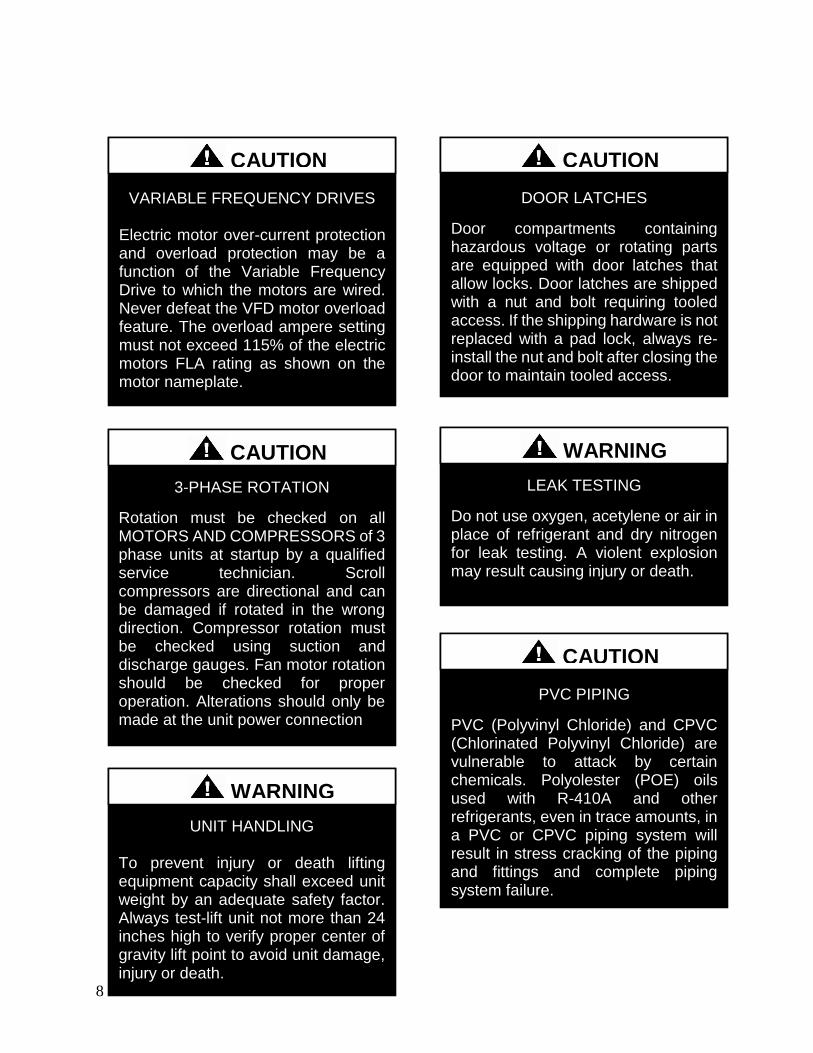
8
LEAK TESTING
Do not use oxygen acetylene or air in place of refrigerant and dry nitrogen for leak testing A violent explosion may result causing injury or death
WARNING
VARIABLE FREQUENCY DRIVES
Electric motor over-current protection and overload protection may be a function of the Variable Frequency Drive to which the motors are wired Never defeat the VFD motor overload feature The overload ampere setting must not exceed 115 of the electric motors FLA rating as shown on the motor nameplate
CAUTION
PVC PIPING
PVC (Polyvinyl Chloride) and CPVC (Chlorinated Polyvinyl Chloride) are vulnerable to attack by certain chemicals Polyolester (POE) oils used with R-410A and other refrigerants even in trace amounts in a PVC or CPVC piping system will result in stress cracking of the piping and fittings and complete piping system failure
CAUTION
3-PHASE ROTATION
Rotation must be checked on all MOTORS AND COMPRESSORS of 3 phase units at startup by a qualified service technician Scroll compressors are directional and can be damaged if rotated in the wrong direction Compressor rotation must be checked using suction and discharge gauges Fan motor rotation should be checked for proper operation Alterations should only be made at the unit power connection
CAUTION
UNIT HANDLING To prevent injury or death lifting equipment capacity shall exceed unit weight by an adequate safety factor Always test-lift unit not more than 24 inches high to verify proper center of gravity lift point to avoid unit damage injury or death
WARNING
DOOR LATCHES
Door compartments containing hazardous voltage or rotating parts are equipped with door latches that allow locks Door latches are shipped with a nut and bolt requiring tooled access If the shipping hardware is not replaced with a pad lock always re-install the nut and bolt after closing the door to maintain tooled access
CAUTION
9
ENCLOSED AREA
Do not work in an enclosed area where refrigerant or nitrogen gases may be leaking A sufficient quantity of vapors may be present and cause
injury or death
WARNING
COMPRESSOR LUBRICANT
Polyolester (POE) and Polyvinylether (PVE) oils are two types of lubricants used in hydrofluorocarbon (HFC) refrigeration systems Refer to the compressor label for the proper compressor lubricant type
CAUTION
COIL CLEANERS
To prevent damage to the unit do not use acidic chemical coil cleaners Do not use alkaline chemical coil cleaners with a pH value greater than 85 after mixing without first using an aluminum corrosion inhibitor in the cleaning solution
CAUTION
COIL CLEANERS
Some chemical coil cleaning compounds are caustic or toxic Use these substances only in accordance with the manufacturerrsquos usage instructions Failure to follow instructions may result in equipment damage injury or death
WARNING
COIL CLEANING
Do not clean DX refrigerant coils with hot water or steam The use of hot water or steam on refrigerant coils will cause high pressure inside the coil tubing and damage to the coil
CAUTION
CONVENIENCE OUTLETS
Factory installed convenience outlets are not intended for use while the unit is operating
WARNING
10
1 Startup and service must be performed by
a Factory Trained Service Technician
2 The unit is for outdoor use only See
General Information section for more
information
3 Every unit has a unique equipment
nameplate with electrical operational
and unit clearance specifications
Always refer to the unit nameplate for
specific ratings unique to the model
purchased
4 READ THE ENTIRE INSTALLATION
OPERATION AND MAINTENANCE
MANUAL OTHER IMPORTANT
SAFETY PRECAUTIONS ARE
PROVIDED THROUGHOUT THIS
MANUAL
5 Keep this manual and all literature
safeguarded near or on the unit
COMPRESSOR CYCLING
5 MINUTE MINIMUM OFF TIME To prevent motor overheating compressors must cycle off for a minimum of 5 minutes
5 MINUTE MINIMUM ON TIME To maintain the proper oil level compressors must cycle on for a minimum of 5 minutes The cycle rate must not exceed 6 starts per hour
WARNING
CF Series Feature String Nomenclature
Model Options Unit Feature Options G
EN
MJ
RE
V
SIZ
E
SE
RIE
S
MN
RE
V
VL
T
A1
A2
A3
A4
A5
1
2A
2B
3A
3B
4
5
6A
6B
6C
7
8A
8B
8C
8D
9
10
11
12
13
14
15
CF A - 015 - B - A - 3 - D C 0 0 K 0 - A 0 - E 0 - C 0 - A N 0 - B - D E 0 0 - 0 0 A 0 E 0 0
0 0 0 0 0 D B
16
17
18
19
20
21
22
11
CF Series Feature String Nomenclature
MODEL OPTIONS Series and Generation
CF
Major Revision
A
Unit Size
002 = 2 ton Capacity
003 = 3 ton Capacity
004 = 4 ton Capacity
005 = 5 ton Capacity
006 = 6 ton Capacity
007 = 7 ton Capacity
009 = 9 ton Capacity
011 = 11 ton Capacity
013 = 13 ton Capacity
015 = 15 ton Capacity
016 = 16 ton Capacity
018 = 18 ton Capacity
020 = 20 ton Capacity
025 = 25 ton Capacity
026 = 26 ton Capacity
030 = 30 ton Capacity
031 = 31 ton Capacity
040 = 40 ton Capacity
050 = 50 ton Capacity
060 = 60 ton Capacity
070 = 70 ton Capacity
Series
A = 2-7 ton units
B = 9-15 ton units
C = 16-25 amp 30 ton units
D = 26 amp 31-70 ton units
Minor Revision
A
Voltage
1 = 230V1Φ60Hz
2 = 230V3Φ60Hz
3 = 460V3Φ60Hz
4 = 575V3Φ60Hz
8 = 208V3Φ60Hz
9 = 208V1Φ60Hz
A1 Compressor Style
0 = Air-Cooled Condenser - No Compressors
(1 Circuit)
A = R-410A Scroll Compressors
B = R-410A Two Step Capacity Scroll Compressors
D = R-410A Variable Capacity Scroll Compressors
E = R-410A Tandem Scroll Compressors
G = R-410A Tandem Variable Capacity Scroll
Compressors
P = Air-Cooled Condenser - No Compressors
(2 Circuits)
Q = Air-Cooled Condenser - No Compressors
(4 Circuits)
A2 Condenser Style
C = Air-Cooled Condenser
J = Air-Source Heat Pump
A3 Configuration
0 = Standard
A4 Coating
0 = Standard
E = Polymer E-Coated Condenser Coil
G = Copper Fin + Stainless Steel Casing - Condenser
Coil
A5 Staging
0 = No Cooling
G = 1 OnOff Refrigeration System
H = 1 Variable Capacity Refrigeration System
J = 2 OnOff Refrigeration Systems
K = 1 Variable Capacity Refrigeration System + 1
OnOff Refrigeration System
L = 2 Variable Capacity Refrigeration System
R = 4 OnOff Refrigeration Systems
T = 2 Variable Capacity Refrigeration Systems + 2
OnOff Refrigeration Systems
U = 4 Variable Capacity Refrigeration Systems
CF Series Feature String Nomenclature
Model Options Unit Feature Options G
EN
MJR
EV
SIZ
E
SE
RIE
S
MN
RE
V
VL
T
A1
A2
A3
A4
A5
1
2A
2B
3A
3B
4
5
6A
6B
6C
7
8A
8B
8C
8D
9
10
11
12
13
14
15
CF A - 015 - B - A - 3 - D C 0 0 K 0 - A 0 - E 0 - C 0 - A N 0 - B - D E 0 0 - 0 0 A 0 E 0 0
0 0 0 0 0 D B
16
17
18
19
20
21
22
12
UNIT FEATURE OPTIONS 1 Unit Orientation
0 = Vertical Condenser Discharge - Standard Access
A = Horizontal Condenser Discharge - Standard
Access
2A Refrigeration Control
0 = Standard
A = 5 Minute Compressor Off Timer + 20 Second
Compressor Stage Delay
C = Adjustable Fan Cycling
D = Adjustable Compressor Lockout
G = Option A + Adjustable Fan Cycling
H = Option A + Adjustable Compressor Lockout
M = Adjustable Fan Cycling + Adjustable
Compressor Lockout
W = Option A + Adjustable Fan Cycling +
Adjustable Compressor Lockout
2B Blank
0 = Standard
3A Refrigeration Options
0 = Standard
A = Hot Gas Bypass Lead Stage [HGB]
B = HGB Lead + HGB Lag
D = Hot Gas Bypass Non-Variable Capacity
Refrigeration Systems [HGBNV]
E = Modulating Hot Gas Reheat [MHGR]
H = HGB + MHGR
J = HGB Lead + HGB Lag + MHGR
L = HGBNV + MHGR
3B Blank
0 = Standard
4 Refrigeration Accessories
0 = Standard
A = Sight Glass
B = Compressor Isolation Valves
C = Options A + B
D = Flooded Condenser 0degF Low Ambient Controls ndash
One Circuit
E = Options A + D
F = Options B + D
G = Options A + B + D
H = Flooded Condenser 0degF Low Ambient Controls-
Two Circuits
J = Options A + H
K = Options B + H
L = Options A + B + H
R = Flooded Condenser 0degF Low Ambient Controls ndash
Four Circuits
S = Options A + R
T = Options B + R
U = Options A + B + R
5 Blank
0 = Standard
6A Unit Disconnect Type
0 = Single Point Power Block
A = Single Point Power Non-Fused Disconnect
6B Disconnect 1 Size
0 = Standard
N = 100 amps
R = 150 amps
V = 250 amps
Z = 400 amps
6C Blank
0 = Standard
CF Series Feature String Nomenclature
Model Options Unit Feature Options
GE
N
MJR
EV
SIZ
E
SE
RIE
S
MN
RE
V
VL
T
A1
A2
A3
A4
A5
1
2A
2B
3A
3B
4
5
6A
6B
6C
7
8A
8B
8
C
8D
9
10
11
12
13
14
15
CF A - 015 - B - 0 - 3 - D C 0 0 K 0 - A 0 - E 0 - C 0 - A N 0 - B - D C 0 0 - 0 0 A 0 E 0 0 0 0 0 0 0 D B
16
17
18
19
20
21
22
13
7 Accessories
0 = Standard
B = Phase amp Brown Out Protection
D = Suction Pressure Transducer on Each
Refrigeration Circuit
E = Compressor Sound Blanket
L = Options B + D
M = Options B + E
Q = Options D + E
1 = Options B + D + E
8A Control Sequence
A = Terminal Block for Thermostat w Isolation
Relays
D = VAV Unit Controller - VAV Cool + CAV Heat
E = CAV Unit Controller
F = Makeup Air Unit Controller - CAV Cool + CAV
Heat
H = Constant Volume HP Unit Controller - CAV
Cool + CAV Heat
J = Makeup Air HP Unit Controller - CAV Cool +
CAV Heat
N = Field Installed DDC Controls by Others with
Isolation Relays
8B Control Suppliers
0 = Standard
E = Orion VCC-X (Main Controller in Air Handling
Unit)
H = AAON Touchscreen Controller (Main Controller
in Air Handling Unit)
8C Control Supplier Options
0 = Standard
8D BMS Connection amp Diagnostics
0 = Standard
9 Blank
0 = Standard
10 Blank
0 = Standard
11 Maintenance Accessories
0 = Standard
A = Factory Wired 115VAC Convenience Outlet
B = Field Wired 115VAC Convenience Outlet
C = Service Lights
E = Remote Unit StartStop Terminals
F = Options A + C
H = Options A + E
J = Options B + C
L = Options B + E
N = Options C + E
R = Options A + C + E
U = Options B + C + E
12 Code Options
0 = Standard ETL USA Listing
B = ETL USA + Canada Listing
13 Air-Cooled Condenser Accessories
0 = Standard
A = Condenser Coil Guard
C = ECM Condenser Fan Head Pressure Control
E = VFD Condenser Fan Head Pressure Control
G = Options A + C
J = Options A + E
N = ECM Condenser Fan Head Pressure Control +
Low Sound Condenser Fan
S = Options A + N
14 Blank
0 = Standard
15 Blank
0 = Standard
16 Electrical Options
0 = Standard
17 Shipping Options
0 = Standard
A = Crating
B = Export Crating
CF Series Feature String Nomenclature
Model Options Unit Feature Options G
EN
MJR
EV
SIZ
E
SE
RIE
S
MN
RE
V
VL
T
A1
A2
A3
A4
A5
1
2A
2B
3A
3B
4
5
6A
6B
6C
7
8A
8B
8C
8D
9
10
11
12
13
14
15
CF A - 015 - B - A - 3 - D C 0 0 K 0 - A 0 - E 0 - C 0 - A N 0 - B - D E 0 0 - 0 0 A 0 E 0 0
0 0 0 0 0 D B 1
6
17
18
19
20
21
22
14
18 Blank
0 = Standard
19 Blank
0 = Standard
20 Cabinet Material
0 = Galvanized Steel Cabinet
21 Warranty
0 = Standard
D = Compressor Warranty - Years 2-5
22 Type
B = Premium AAON Gray Paint Exterior
E = Premium AAON Gray Paint Ext + Shrink Wrap
X = SPA + Premium AAON Gray Paint Exterior
1 = SPA + Premium AAON Gray Paint Exterior +
Shrink Wrap
15
General Information
AAON CF Series air-cooled condensers and
condensing units have been designed for
outdoor use only They are factory
assembled wired charged and run-tested
Codes and Ordinances
CF Series units have been tested and
certified by ETL in accordance with UL
Safety Standard 1995CSA C222 No 236
System should be sized in accordance with
the American Society of Heating
Refrigeration and Air Conditioning
Engineers Handbook
Installation of CF Series units must conform
to the ICC standards of the International
Mechanical Code the International Building
Code and local building plumbing and
electrical codes All appliances must be
electrically grounded in accordance with
local codes or in the absence of local codes
the current National Electric Code
ANSINFPA 70 or the current Canadian
Electrical Code CSA C221
Receiving Unit
When received the unit should be checked
for damage that might have occurred in
transit If damage is found it should be noted
on the carrierrsquos freight bill A request for
inspection by carrierrsquos agent should be made
in writing at once Nameplate should be
checked to ensure the correct model sizes and
voltages have been received to match the job
requirements
If repairs must be made to damaged goods
then the factory should be notified before any
repair action is taken in order to protect the
warranty Certain equipment alteration
repair and manipulation of equipment
without the manufacturerrsquos consent may void
the product warranty Contact AAON
Technical Support for assistance with
handling damaged goods repairs and freight
claims (918) 382-6450
SHARP EDGES
Coils and sheet metal surfaces present sharp edges and care must be taken when working with equipment
WARNING
QUALIFIED INSTALLER
Improper installation adjustment alteration service or maintenance can cause property damage personal injury or loss of life Installation and service must be performed by a Factory Trained Service Technician
WARNING
Failure to observe the following instructions will result in premature failure of your system and possible voiding of the warranty
WARNING
16
Storage
If installation will not occur immediately
following delivery store equipment in a dry
protected area away from construction traffic
and in the proper orientation as marked on the
packaging with all internal packaging in
place Secure all loose-shipped items
Failure to observe the following instructions
will result in premature failure of your
system and possible voiding of the warranty
Never turn off the main power supply to the
unit except for complete shutdown When
power is cut off from the unit any
compressors using crankcase heaters cannot
prevent refrigerant migration This means the
compressor will cool down and liquid
refrigerant may accumulate in the
compressor The compressor is designed to
pump refrigerant gas and damage may occur
if liquid enters the compressor when power is
restored
Before unit operation the main power switch
must be turned on for at least twenty-four
hours for units with compressor crankcase
heaters This will give the crankcase heater
time to clear any liquid accumulation out of
the compressor before it is required to run
Always control the system from the control
panel never at the main power supply (except
for emergency or for complete shutdown of
the system)
CLEAN AIR ACT
The Clean Air Act of 1990 bans the intentional venting of refrigerant as of July 1 1992 Approved methods of recovery recycling or reclaiming must be followed
CAUTION
CRANKCASE HEATER OPERATION
Units are equipped with compressor crankcase heaters which should be energized at least 24 hours prior to cooling operation to clear any liquid refrigerant from the compressors
CAUTION
3-PHASE ROTATION
Rotation must be checked on all MOTORS AND COMPRESSORS of three phase units All motors to include and not be limited to pump motors and condenser fan motors should all be checked by a qualified service technician at startup and any wiring alteration should only be made at the unit power connection
CAUTION
17
The standard compressors must be on a
minimum of 5 minutes and off for a minimum
of 5 minutes The cycle rate must be no more
than 6 starts per hour
The variable capacity compressors must be
on a minimum of 3 minutes and off for a
minimum of 3 minutes The cycle rate must
be no more than 6 starts per hour
The compressor life will be seriously
shortened by reduced lubrication and the
pumping of excessive amounts of liquid oil
and liquid refrigerant
Wiring Diagrams
A complete set of unit specific wiring
diagram in point-to-point form is laminated
in plastic and located inside the control
compartment door
General Maintenance
When the initial startup is made and on a
periodic schedule during operation it is
necessary to perform routine service checks
on the performance of the condensing unit
This includes reading and recording suction
pressures and checking for normal sub-
cooling and superheat
COMPRESSOR ROTATION
Scroll compressors are directional and will be damaged by operation in the wrong direction Low pressure switches on compressors have been disconnected after factory testing Rotation should be checked by a qualified service technician at startup using suction and discharge pressure gauges and any wiring alteration should only be made at the unit power connection
COMPRESSOR CYCLING
5 MINUTE MINIMUM OFF TIME To prevent motor overheating compressors must cycle off for a minimum of 5 minutes
5 MINUTE MINIMUM ON TIME To maintain the proper oil level compressors must cycle on for a minimum of 5 minutes The cycle rate must not exceed 6 starts per hour
WARNING
CAUTION
18
Installation
Forklifting the Unit
CF Series condensing unit sizes 2-25 amp 30
tons can be lifted using a forklift 2-7 ton
units must have forks at least 48rdquo in length
9-25 amp 30 ton units must have forks 72rdquo in
length or the forks must have 72rdquo fork
extensions Standard units can be lifted from
all sides except the condenser coil side CF
Series condensing unit sizes 26 amp 31-70 tons
cannot be lifted using a forklift They can be
lifted as shown in Figure 3
Forks must be perpendicular to the unit and
they must be in far enough that the back of
the forks are no more than 6rdquo away from the
edge of the unit
Figure 1 - Forklifting a CF Series A Cabinet
Figure 2 - Forklifting a CF Series B and C
Cabinet
FORKLIFTING 2-7 TON UNITS
Forks or Fork Extensions must be at least 48rdquo in length
CAUTION
FORKLIFTING 9-25 amp 30 TON UNITS
Forks or Fork Extensions must be at least 72rdquo in length
CAUTION
19
Lifting the Unit
If cables or chains are used to hoist the unit
they must be the same length Minimum
cable length is 99rdquo for CF Series 9-70 ton
units CF Series 2-7 ton units do not include
factory installed lifting lugs and should be
lifted by forklift only Care should be taken
to prevent damage to the cabinet coils and
condenser fans
Before lifting unit be sure that all shipping
material has been removed from unit Secure
hooks and cables at all lifting points lugs
provided on the unit
Figure 3 ndash Lifting Details and Orientation of
a CF Series 9-70 ton Condensing Unit
Locating the Unit
The CF Series condenser and condensing unit
is designed for outdoor applications and
mounting at ground level or on a rooftop It
must be placed on a level and solid
foundation that has been prepared to support
its weight When installed at ground level a
one-piece concrete slab should be used with
footings that extend below the frost line Also
with ground level installation care must be
taken to protect the coil fins from damage due
to vandalism or other causes
The first clearance table below gives the
clearance values for proper unit operation
The second clearance table gives the
clearance necessary for removing the coil
without disassembling a large part of the
condensing unit For ease of removing the
condenser coil use the second table
clearances for the right hand side of the unit
Table 1 ndashClearances for Proper Operation
Location Unit Size
2-7 tons 9-70 tons
Front -
(Controls
Side)
Unobstructed 36rdquo
Left Side 6rdquo 30rdquo
Right Side 6rdquo 36rdquo
Top 3rdquo Unobstructed
Back 18rdquo 6rdquo
Table 2 ndash Clearances for Coil Pull
Unit Size Right Hand Side
2-7 tons 42rdquo
9-15 tons 42rdquo
16-25 amp 30 tons 54rdquo
26 amp 31-70 tons 66rdquo
Figure 4 - Orientation of Series 2-7 ton
Condensing Unit
20
The placement relative to the building air
intakes and other structures must be carefully
selected Airflow to and from the condenser
or condensing unit must not be restricted to
prevent a decrease in performance and
efficiency
The installation position for 9-70 ton units
must provide at least 30rdquo of left and right side
clearance for proper airflow to the condenser
coils When units are mounted adjacent to
each other the minimum right and left side
clearance required between the units is 60rdquo or
5 feet Similarly when 2-7 ton units are
mounted adjacent to each other the minimum
clearance required between the back side of
the units is 36rdquo or 3 feet
Units should not be installed in an enclosure
or pit that is deeper than the height of the unit
When recessed installation is necessary the
clearance to maintain proper airflow is at
least 5 feet (3 feet for 2-7tons)
CF Series condensers and condensing units
that have a vertical air discharge must have
no obstruction above the equipment Do not
place the unit under an overhang CF Series
condensers and condensing units that have a
horizontal discharge must have no
obstruction in front of the unit
For proper unit operation the immediate area
around condenser must remain free of debris
that may be drawn in and obstruct airflow in
the condensing section
Consideration must be given to obstruction
caused by snow accumulation when placing
the unit
Mounting Isolation
For roof mounted applications or anytime
vibration transmission is a factor vibration
isolators may be used
Access Doors
Access doors are provided to the compressor
and electrical compartment
Standard Evacuation Instructions
Proper system evacuation is critical to
remove moisture and non-condensables from
the system before charging the system with
refrigerant A newly installed AAON
condensing unit has already been evacuated
and charged with some refrigerant at the
factory When evacuating a new system
keep the condensing unit service valves
closed and evacuate the suction and liquid
lines and the air handling unit If the entire
system must be evacuated use the following
procedure to ensure the entire system is
pulled into a good vacuum
1 System evacuation should be
performed anytime a system is open to
atmospheric pressure The POE oils
used with R-410A are extremely
hydroscopic in nature and immediately
begin pulling in moisture once the
system is opened to the atmosphere
2 Before starting to evacuate the
system you MUST ensure that there are
no leaks by pressurizing the system with
PVC PIPING
PVC (Polyvinyl Chloride) and CPVC (Chlorinated Polyvinyl Chloride) are vulnerable to attack by certain chemicals Polyolester (POE) oils used with R-410A and other refrigerants even in trace amounts in a PVC or CPVC piping system will result in stress cracking of the piping and fittings and complete piping system failure
CAUTION
21
400 psig of dry nitrogen and verifying no
pressure loss after one hour
3 Four valve manifold gauge sets are
more effective than standard manifold
gauge sets due to the extra hose port in
combination with a 38rsquorsquo evacuation
port The larger diameter evacuation port
will expedite system evacuation
4 The manifold set should be connected
to the condensing unit with one hose on
the suction line service valve one hose
on the liquid line service valve and if an
extra Schrader valve is field installed on
the suction line connect a third hose (not
shown) The vacuum pump should be
connected to the manifold set using a
38rdquo vacuum rated hose Figure 5 shows
two circuits Both circuits must be
evacuated separately
Figure 5 ndash CU evacuation connections
5 An accurate micron gauge must be
used and checked by pulling a vacuum
on the gauge by itself and verify a rapid
drop to less than 100 microns within a
few minutes
6 The micron gauge should not be
attached to the system until the gauge
manifold is reading 28rsquorsquo of vacuum to
ensure the micron gauge does not see
pressure and is thus damaged MICRON
GAUGES WILL BE DAMAGED BY
PRESSURE
7 It is a good practice to replace the
vacuum pump oil after one hour of the
evacuation process The oil can be
broken down in the pump in the initial
first hour causing system evacuation to
take longer than it should
8 The minimum micron level required
by AAON is 350 microns for systems
using POE oils
9 The system should then be isolated
and the pump turned off to check for
vacuum rise due to leaks or moisture in
the system The micron gauge should
not rise above 500 microns after 30
minutes of wait time
Low Ambient amp Modulating Reheat
System Evacuation Instructions
Proper system evacuation is critical to
remove moisture and non-condensables from
the system before charging the system with
refrigerant Systems with low ambient
flooded condenser option require the
following procedure to ensure the entire
system is pulled into a good vacuum
1 System evacuation should be
performed anytime a system is open to
atmospheric pressure The POE oils
used with R-410A are extremely
hydroscopic in nature and immediately
begin pulling in moisture once the
system is opened to the atmosphere
2 Open the reheat valve to 50 when
evacuating
3 Before starting to evacuate the
system you MUST ensure that there are
no leaks by pressurizing the system with
22
400 psig of dry nitrogen and verifying no
pressure loss after one hour
4 Four valve manifold gauge sets are
more effective than standard manifold
gauge sets due to the extra hose port in
combination with a 38rsquorsquo evacuation
port The larger diameter evacuation port
will expedite system evacuation
5 The manifold set should be connected
to the condensing unit with one hose on
the suction line service valve one hose
on the liquid line service valve and a
third hose on the reheat line service
valve The vacuum pump should be
connected to the manifold set using a
38rdquo vacuum rated hose Figure 6 shows
two circuits The first circuit has a
reheat line the second circuit is just the
suction and liquid line Both circuits
must be evacuated separately
Figure 6 ndash CU evacuation connections
6 FAILURE to connect to the liquid
line service valve will result in the
receiver tank not being fully evacuated
and most likely lead to non-
condensables in the system
7 An accurate micron gauge must be
used and checked by pulling a vacuum
on the gauge by itself and verify a rapid
drop to less than 100 microns within a
few minutes
8 The micron gauge should not be
attached to the system until the gauge
manifold is reading 28rsquorsquo of vacuum to
ensure the micron gauge does not see
pressure and is thus damaged MICRON
GAUGES WILL BE DAMAGED BY
PRESSURE
9 It is a good practice to replace the
vacuum pump oil after one hour of the
evacuation process The oil can be
broken down in the pump in the initial
first hour causing system evacuation to
take longer than it should
10 The minimum micron level required
by AAON is 350 microns for systems
using POE oils
11 The system should then be isolated
and the pump turned off to check for
vacuum rise due to leaks or moisture in
the system The micron gauge should
not rise above 500 microns after 30
minutes of wait time
Adjusting Refrigerant Charge
All AAON CF Series condensers and
condensing units are shipped with a factory
holding charge The factory charge is
different depending on the unit size and
system (heat pump modulating hot gas
reheat LAC) The factory charge per circuit
is shown on the unit nameplate Adjusting the
charge of the system will be required during
installation
23
Adjusting the charge of a system in the field
must be based on determination of liquid sub-
cooling and evaporator superheat On a
system with a thermostatic expansion valve
liquid sub-cooling is more representative of
the charge than evaporator superheat but both
measurements must be taken
Before Charging
Refer to the Unit Nameplate to determine
which refrigerant must be used to charge the
system
Unit being charged must be at or near full
load conditions before adjusting the charge
Units equipped with hot gas bypass must
have the hot gas bypass valve closed to get
the proper charge
Units equipped with hot gas reheat must be
charged with the hot gas valve closed while
the unit is in cooling mode After charging
unit should be operated in reheat
(dehumidification) mode to check for correct
operation
Units equipped with heat pump options
should be charged in cooling mode to get the
proper charge After charging unit should be
operated in heating mode to check for correct
charge Charge may need to be adjusted for
heating mode If adjustments are made in the
heating mode cooling mode must be rerun to
verify proper operation
After adding or removing charge the system
must be allowed to stabilize typically 10-15
minutes before making any other
adjustments
The type of unit and options determine the
ranges for liquid sub-cooling and evaporator
superheat Refer to Table 3 when determining
the proper sub-cooling
For units equipped with low ambient (0degF)
option see the special charging instructions at
the end of this section
Checking Liquid Sub-cooling
Measure the temperature of the liquid line as
it leaves the condenser coil
Read the gauge pressure at the liquid line
close to the point where the temperature was
taken You must use liquid line pressure as it
will vary from discharge pressure due to
condenser coil pressure drop
Convert the pressure obtained to a saturated
temperature using the appropriate refrigerant
temperature-pressure chart
COMPRESSOR LUBRICANT
Polyolester (POE) and Polyvinylether (PVE) oils are two types of lubricants used in hydrofluorocarbon (HFC) refrigeration systems Refer to the compressor label for the proper compressor lubricant type
CAUTION
CLEAN AIR ACT
The Clean Air Act of 1990 bans the intentional venting of refrigerant (CFCrsquos and HCFCrsquos) as of July 1 1992 Approved methods of recovery recycling or reclaiming must be followed Fines andor incarceration may be levied for non-compliance
CAUTION
24
Subtract the measured liquid line temperature
from the saturated temperature to determine
the liquid sub-cooling
Compare calculated sub-cooling to Table 3
for the appropriate unit type and options
Table 3 - Acceptable Refrigeration Circuit
Values
Cooling
Mode
Liquid Sub-
Cooling
Values
Cooling Only Unit4 8-15degF
Cooling Only Unit with Hot
Gas Reheat14 5-15degF
Heat PumpUnit24 2-4degF
Heat Pump Unit with Hot
Gas Reheat34 2-6degF
Cooling Only Unit with
LAC4 8-15degF
Cooling Only Unit with Hot
Gas Reheat amp LAC4 8-15degF
Notes 1 Must be charged with the hot gas valve
closed After charging unit should be
operated in reheat (dehumidification) mode
to check for correct operation
2 The sub-cooling value in this table is for the
unit running in cooling mode of operation
After charging unit should be operated in
heating mode to check for correct operation
3 The sub-cooling value in this table is for the
unit running in cooling mode of operation
and the hot gas valve closed After charging
unit should be operated in reheat
(dehumidification) mode to check for correct
operation and then in heating mode to check
for correct operation
4 Sub-cooling must be increased by 1degF per 10
feet of vertical liquid line rise for R-410A
(AHU above CU) For example a cooling
only unit with hot gas reheat and a vertical
liquid drop can charge to a sub-cooling value
of 5-15degF but a cooling only unit with hot
gas reheat and a vertical liquid rise of 30 ft
must charge to a sub-cooling value of at least
8-15degF DO NOT OVERCHARGE
Refrigerant overcharging leads to excess
refrigerant in the condenser coils resulting in
elevated compressor discharge pressure
Checking Evaporator Superheat
Measure the temperature of the suction line
close to the compressor
Read gauge pressure at the suction line close
to the compressor
Convert the pressure obtained to a saturated
temperature using the appropriate refrigerant
temperature-pressure chart
Subtract the saturated temperature from the
measured suction line temperature to
determine the evaporator superheat
For refrigeration systems with tandem
compressors it is critical that the suction
superheat setpoint on the TXV is set with one
compressor running The suction superheat
should be 10-13degF with one compressor
running The suction superheat will increase
with both compressors in a tandem running
Inadequate suction superheat can allow liquid
refrigerant to return to the compressors which
will wash the oil out of the compressor Lack
of oil lubrication will destroy a compressor
Liquid sub-cooling should be measured with
both compressors in a refrigeration system
running
Compare calculated superheat to the
acceptable cooling mode superheat values of
8-15degF for all system types Superheat will
increase with long suction line runs
25
Adjusting Sub-cooling and Superheat
Temperatures
The system is overcharged if the sub-cooling
temperature is too high compared to Table 3
and the evaporator is fully loaded (low loads
on the evaporator result in increased sub-
cooling) and the evaporator superheat is
within the temperature range of 8-15degF (high
superheat results in increased sub-cooling)
Correct an overcharged system by reducing
the amount of refrigerant in the system to
lower the sub-cooling
The system is undercharged if the superheat
is too high and the sub-cooling is too low
Correct an undercharged system by adding
refrigerant to the system to reduce superheat
and raise sub-cooling
If the sub-cooling is correct and the superheat
is too high the TXV may need adjustment to
correct the superheat
DO NOT OVERCHARGE Refrigerant overcharging leads to excess refrigerant in the condenser coils resulting in elevated compressor discharge pressure
CAUTION
EXPANSION VALVE ADJUSTMENT
Thermal expansion valves must be adjusted to approximately 8-15degF of suction superheat Failure to have sufficient superheat will damage the compressor and void the warranty
CAUTION
26
Special Low Ambient Option Charging
Instructions
For units equipped with low ambient
refrigerant flood back option being charged
in the summer when the ambient
temperature is warm
If the ambient is above 70degF charge to
approximately 1-2degF of sub-cooling
measured at the inlet to the expansion valve
Once enough charge has been added to get
the evaporator superheat and sub-cooling
values to the correct setting more charge
must be added Use Table 4 to find the
additional charge amount required for the
system when running in cold ambient
conditions
Table 4 ndash Charge to Flood Condenser Coil
for Ambient Above 70degF
CF Size of
circuits
Per Circuit
Charge (lbs)
CF 2 3 1 49
CF 4 5 6 7 1 92
CF 9 11 2 91
CF 13 15 2 121
CF 16 18 2 131
CF 20 25 30 2 175
CF 26 31 40 2 180
4 91
CF 50 60 70 2 438
4 221
For units equipped with low ambient
refrigerant flood back option being charged
in the winter when the ambient
temperature is cold
1 If the ambient is below 70degF charge
to approximately 1-2degF of sub-cooling
measured at the inlet to the expansion
valve Once enough charge has been
added to get the evaporator superheat
and sub-cooling values to the correct
setting more charge may need to be
added If the ambient temperature is 0degF
no more charge is required Ambient
temperatures above 0degF will require a
percentage of the per circuit charge
values from Table 4 Using your
ambient temperature find the
percentage value from Table 5 and
multiply the Per Circuit Charge value
from Table 4 and the value to
determine the additional charge amount
Table 5 ndash Charge to Flood Condenser
Coil for Ambient Below 70degF
Condenser
Ambient
Temperature ˚F
Percentage
Per Circuit
Charge from
Table 4
60 60
50 37
40 24
30 15
20 8
0 0
2 The unit should be checked for proper
operation once the ambient temperature
is above 80degF
Example A CF size 31 with tandem
compressors where the ambient
temperature is 40degF
From Table 4 ndash 18 lbs refrigerant charge
per circuit (tandem compressors would
have 2 circuits in this size of CF)
From Table 5 ndash 24 of Table 4 charge
Additional charge needed for a unit with
low ambient flooded condenser controls
= 18 lbs 024 = 432 lbs additional
refrigerant charge per circuit
27
Low Ambient Operation
During low ambient temperatures the vapor
refrigerant will migrate to the cold part of the
system and condense into liquid All CF
Series compressors are provided with factory
installed crankcase heaters to help prevent
liquid refrigerant from slugging the
compressors during startup in low ambient
conditions The condenser or condensing unit
must have continuous power 24 hours prior
to startup This ensures the compressor will
receive sufficient refrigerant vapor at startup
Standard units can operate down to 55degF
ambient temperature
AAON condenser fan head pressure control
units can operate down to 35degF ambient
temperature Three different condenser fan
head pressure control options available are
adjustable fan cycling ECM condenser fan
or VFD controlled condenser fans See
detailed information following
The AAON low ambient (condenser flood-
back) system is used to operate a refrigerant
system down to 0degF outside air temperature
See detailed information following
Fan Cycling Low Ambient
Adjustable fan cycling is a low ambient head
pressure control option that cycles the
condenser fans to maintain refrigerant circuit
head pressures at acceptable levels during
cooling operation The head pressure set
point (100-470 psi) and pressure differential
(35-200 psi) can be field adjusted using a
flathead screwdriver For example if the
head pressure is set to 300psi and the
differential is set to 100psi then fans will cut
in at 300psi and cut out at 200psi Fan
cycling and variable speed condenser fan
head pressure control options allow
mechanical cooling with ambient
temperatures down to 35degF
Figure 7 - Adjustable Fan Cycling Switch
Variable Speed Low Ambient
Variable speed condenser fan head pressure
control is a low ambient head pressure
control option that sends a variable signal in
relation to the refrigerant circuit head
pressure of the system to an electronically
commutated motor (ECM) or VFD The
motor either speeds up or slows down air
flow accordingly in order to maintain
constant head pressure Fan cycling and
variable speed condenser fan head pressure
control options allow mechanical cooling
with ambient temperatures down to 35degF
Flooded Condenser Low Ambient
Flooded condenser low ambient control
maintains normal head pressure during
periods of low ambient When the ambient
temperature drops the condensing
temperature and therefore pressure drops
Without ambient control the system would
shut down on low discharge pressure The
flooded condenser method of low ambient
control fills the condenser coil with liquid
refrigerant decreasing the heat transfer
capacity of the coil which allows the coil to
operate at an acceptable discharge pressure
28
The condenser coil will not be flooded during
summer ambient temperatures so a receiver
is included to store the additional liquid
refrigerant required to flood the condenser
coil in low ambient The receiver is factory-
sized to contain all of the flooded volume
Without a receiver there would be high head
pressures during higher ambient conditions
The low ambient system maintains normal
head pressure during periods of low ambient
by restricting liquid flow from the condenser
to the receiver and at the same time
bypassing hot gas around the condenser to the
inlet of the receiver This reduces liquid
refrigerant flow from the condenser reducing
its effective surface area which in turn
increases the condensing pressure At the
same time the bypassed hot gas raises liquid
pressure in the receiver allowing the system
to operate properly CF Series condensers
and condensing units use an LAC valve for
low ambient operation
LAC Valve
The Low Ambient Control (LAC) valve is a
non-adjustable three way valve that
modulates to maintain receiver pressure As
the receiver pressure drops below the valve
setting (295 psig for R-410A) the valve
modulates to bypass discharge gas around the
condenser The discharge gas warms the
liquid in the receiver and raises the pressure
to the valve setting The following schematic
shows an example system using the LAC
valve
Figure 8 ndash LAC Piping Example
29
Refrigerant Piping
(See back of the manual for refrigerant piping
diagrams)
General
Piping from the condensing unit to the air
handler is the responsibility of the installing
contractor
Use only clean type ldquoACRrdquo copper tubing
that has been joined with high temperature
brazing alloy
The pipe or line sizes must be selected to
meet the actual installation conditions and
NOT simply based on the connection sizes at
the condensing unit or air handler
All CF Series condensing units are provided
with in-line shutoff valves on both the liquid
and suction lines These should remain closed
until the system is ready for start-up after
installation
Piping should conform to generally accepted
practices and codes
Care must be taken not to cross the circuits
on multiple circuit systems
Upon completion of piping connection the
interconnecting piping and air handler MUST
BE evacuated to 500 microns or less leak
checked and charged with refrigerant
Determining Refrigerant Line Size
The piping between the condenser and low
side must ensure
1 Minimum pressure drop and
2 Continuous oil return and
3 Prevention of liquid refrigerant slugging
or carryover
Minimizing the refrigerant line size is
favorable from an economic perspective
reducing installation costs and reducing the
potential for leakage However as pipe
diameters decrease pressure drop increases
Excessive suction line pressure drop causes
loss of compressor capacity and increased
power usage resulting in reduced system
efficiency Excessive pressure drops in the
liquid line can cause the liquid refrigerant to
flash resulting in faulty TXV operation and
improper system performance In order to
operate efficiently and cost effectively while
avoiding malfunction refrigeration systems
must be designed to minimize both cost and
pressure loss
REFRIGERANT PIPING
Line sizes must be selected to meet actual installation conditions not simply based on the connection sizes at the condensing unit or air handling unit
CAUTION
REFRIGERANT PIPING
This section is for information only and is not intended to provide all details required by the designer or installer of the refrigerant piping between the condenser or condensing unit and the air handling unit AAON Inc is not responsible for interconnecting refrigerant piping Consult ASHRAE Handbook ndash Refrigeration and ASME Standards
CAUTION
30
Equivalent Line Length
All line lengths discussed in this manual
unless specifically stated otherwise are
Equivalent Line Lengths The frictional
pressure drop through valves fittings and
accessories is determined by establishing the
equivalent length of straight pipe of the same
diameter Always use equivalent line
lengths when calculating pressure drop
Special piping provisions must be taken
when lines are up vertical risers or in
excessively long line runs AAON does not
recommend running underground
refrigerant lines
Liquid Line
When sizing the liquid line it is important to
minimize the refrigerant charge to reduce
installation costs and improve system
reliability This can be achieved by
minimizing the liquid line diameter
However reducing the pipe diameter will
increase the velocity of the liquid refrigerant
which increases the frictional pressure drop
in the liquid line and causes other
undesirable effects such as noise
Maintaining the pressure in the liquid line is
critical to ensuring sufficient saturation
temperature avoiding flashing upstream of
the TXV and maintaining system efficiency
Pressure losses through the liquid line due to
frictional contact installed accessories and
vertical risers are inevitable Maintaining
adequate sub-cooling at the condenser to
overcome these losses is the only method to
ensure that liquid refrigerant reaches the
TXV
Liquid refrigerant traveling upwards in a riser
loses head pressure If the evaporator is
below the condenser with the liquid line
flowing down the gravitational force will
increase the pressure of the liquid refrigerant
This will allow the refrigerant to withstand
greater frictional losses without the
occurrence of flashing prior to the TXV
A moisture-indicating sight glass may be
field installed in the liquid line to indicate the
occurrence of premature flashing or moisture
in the line The sight glass should not be used
to determine if the system is properly
charged Use temperature and pressure
measurements to determine liquid sub-
cooling not the sight glass
Liquid Line Routing
Care should be taken with vertical risers
When the system is shut down gravity will
pull liquid down the vertical column and
back to the condenser when it is below the
evaporator This could potentially result in
compressor flooding A check valve can be
installed in the liquid line where the liquid
column rises above the condenser to prevent
this The liquid line is typically pitched along
with the suction line or hot gas line to
minimize the complexity of the
configuration
Liquid Line Insulation
In cooling only systems when the liquid line
is routed through regions where temperature
losses are expected no insulation is required
as this may provide additional sub-cooling to
the refrigerant When routing the liquid line
through high temperature areas insulation of
the line is appropriate to avoid loss of sub-
cooling through heat gain
In heat pump systems when the liquid line is
routed through regions where temperature
losses are expected (all lines exposed to
outside air conditions) insulate with a
minimum 1 inch thick Armaflex insulation
as this will prevent capacity loss during
heating mode of operation
31
Liquid Line Guidelines
In order to ensure liquid at the TXV the sum
of frictional losses and pressure loss due to
vertical rise must not exceed available sub-
cooling A commonly used guideline to
consider is a system design with pressure
losses due to friction through the line not to
exceed a corresponding 1-2degF change in
saturation temperature An additional
recommendation is that the sum of frictional
losses (including valve losses filter drier
losses other accessories and line losses) and
pressure loss due to vertical rise should not
exceed 8degF if the available sub-cooling is
10degF
If the velocity of refrigerant in the liquid line
is too great it could cause excessive noise or
piping erosion The recommended maximum
velocities for liquid lines are 100 fpm from
the condenser to a receiver to discourage
fluid backup and 500 fpm from receiver tank
to the evaporator (300 fpm if the line includes
an electric valve to minimize valve induced
liquid hammer)
Liquid Line Accessories
Liquid line shut off valves and filter driers are
factory provided The total length equivalent
of pressure losses through valves elbows and
fittings must be considered when adding
additional components in the field It is a
good practice to utilize the fewest elbows that
will allow the mating units to be successfully
joined
A liquid line receiver is factory installed on
units with modulating hot gas reheat units
with low ambient control flooded condenser
and units with heat pump
Suction Line
The suction line is more critical than the
liquid line from a design and construction
standpoint More care must be taken to
ensure that adequate velocity is achieved to
return oil to the compressor at minimum
loading conditions However reducing the
piping diameter to increase the velocity at
minimal load can result in excessive pressure
losses capacity reduction and noise at full
load
Suction Line Routing
For cooling only systems pitch the suction
line in the direction of flow (about 1 inch per
20 feet of length) to maintain oil flow
towards the compressor and keep it from
flooding back into the evaporator
For heat pump systems do not pitch lines
since they will be flowing in one direction in
cooling mode and the opposite direction in
heating mode
Crankcase heaters are provided to keep any
condensed refrigerant that collects in the
compressor from causing damage or wear
Make sure to provide support to maintain
suction line positioning and insulate
completely between the evaporator and
condensing unit
It is important to consider part load operation
when sizing suction lines At minimum
capacity refrigerant velocity may not be
adequate to return oil up the vertical riser
Decreasing the diameter of the vertical riser
will increase the velocity but also the
frictional loss
For difficult line routing applications a
double suction riser can be applied to the
situation of part load operation with a suction
riser A double suction riser is designed to
return oil at minimum load while not
incurring excessive frictional losses at full
load A double suction riser consists of a
small diameter riser in parallel with a larger
diameter riser and a trap at the base of the
large riser At minimum capacity refrigerant
velocity is not sufficient to carry oil up both
32
risers and it collects in the trap effectively
closing off the larger diameter riser and
diverting refrigerant up the small riser where
velocity of the refrigerant is sufficient to
maintain oil flow At full load the mass flow
clears the trap of oil and refrigerant is carried
through both risers The smaller diameter
pipe should be sized to return oil at minimum
load while the larger diameter pipe should be
sized so that flow through both pipes
provides acceptable pressure drop at full
load
Figure 9 - Double Suction Riser
Construction
A double riser can also be used for heat pump
operation The specific volume (ft3lb) of
refrigerant at the discharge temperature and
pressure (heating mode line conditions) is
significantly lower than the specific volume
at the suction temperature and pressure
(cooling mode line conditions) To
compound the issue the capacity in heating
mode is lower than the capacity in cooling
mode The discharge velocity in the riser
during heating mode is much lower than the
suction velocity during cooling mode Often
a double riser is necessary to get acceptable
velocities for the discharge mode and
acceptable velocities for the suction mode In
the example diagrams (See Figure 10 amp
Figure 11) the cooling mode will use both
lines and the heating mode will use only one
Suction Line Traps
Include a trap immediately after the
evaporator coil outlet to protect the TXV bulb
from liquid refrigerant
Include traps every 20 feet in vertical suction
riser sections for cooling only systems and
every 12 feet for heat pump systems
Suction Line Insulation
The entire suction line should be insulated
with a minimum 1 inch thick Armaflex
insulation This prevents condensation from
forming on the line and reduces any potential
loss in capacity associated with heat gain
placing additional load on the system This
line should still be insulated in heat pump
systems even though it acts as both a
discharge and suction line
Suction Line Guidelines
For proper performance suction line
velocities less than a 4000 fpm maximum are
recommended The minimum velocity
required to return oil is dependent on the pipe
diameter however a general guideline of
1000 fpm minimum may be applied
When suction flow is up variable capacity
compressors require a minimum velocity of
1500 fpm at full load
Tandem compressors must be considered for
full load operation (both compressors
operating) and at partial load (only one
compressor operating) When suction flow is
up and the tandem has a variable capacity
compressor the velocity for only one
compressor in operation must be greater than
1500 fpm For onoff compressors the
velocity must be greater than the minimum
velocity required to return oil
Heat pump vapor lines must be checked for
suction flow (cooling mode operation) and
discharge flow (heating mode operation)
33
The same line must be used for both modes
of operation
In a fashion similar to the liquid line a
common guideline to consider is a system
design with pressure losses due to friction
through the line not to exceed a
corresponding 1-2degF change in saturation
temperature
For split system piping with long horizontal
runs and short vertical risers a smaller pipe
size can be used to provide sufficient velocity
to return oil in vertical risers at part loads and
a larger size pipe can be used on the
horizontal runs and vertical drop sections
This helps with oil return yet keeps the
pressure drop to a minimum
Suction Line Accessories
If the job requirements specify suction
accumulators they must be separately
purchased and field installed Heat pump
units will include a factory installed suction
accumulator
Discharge Line
The discharge line is similar to the suction
line from a design and construction
standpoint Care must be taken to ensure that
adequate velocity is achieved to return oil to
the compressor at minimum loading
conditions However reducing the piping
diameter to increase the velocity at minimal
load can result in excessive pressure losses
capacity reduction and noise at full load
Pressure loss in the discharge line has less of
an impact on capacity than pressure loss in
the suction line Pressure loss in the
discharge line causes the compressors to
work harder and thus use more power
Discharge Line Routing
For cooling only remote condenser systems
pitch the discharge line in the direction of
flow (about 1 inch per 20 feet of length) to
maintain oil flow towards the compressor
In a heat pump system the field installed
suction line is also used as a discharge line in
the heating mode of operation so the line
must be sized to meet both the suction line
conditions in cooling mode and the discharge
line conditions in heating mode
Because it is used in both directions for a heat
pump unit the line should be installed level
not pitched to facilitate oil return in both
modes of operation
It is important to consider part load operation
when sizing discharge lines At minimum
capacity refrigerant velocity may not be
adequate to return oil up the vertical riser
Decreasing the diameter of the vertical riser
will increase the velocity but also the
frictional loss
For difficult line routing applications a
double discharge riser can be applied to the
situation of part load operation with a
discharge riser A double discharge riser is
designed to return oil at minimum load while
not incurring excessive frictional losses at
full load A double discharge riser consists of
a small diameter riser in parallel with a larger
diameter riser and a trap at the base of the
large riser At minimum capacity refrigerant
velocity is not sufficient to carry oil up both
risers and it collects in the trap effectively
closing off the larger diameter riser and
diverting refrigerant up the small riser where
SUCTION RISER TRAPS
Circuits require suction riser traps every 20 feet (every 12 feet for heat pumps)
CAUTION
34
velocity of the refrigerant is sufficient to
maintain oil flow At full load the mass flow
clears the trap of oil and refrigerant is carried
through both risers The smaller diameter
pipe should be sized to return oil at minimum
load while the larger diameter pipe should be
sized so that flow through both pipes
provides acceptable pressure drop at full
load (See the Double Suction Riser
Construction Figure 9)
A double riser can also be used for heat pump
operation The specific volume (ft3lb) of
refrigerant at the discharge temperature and
pressure (heating mode line conditions) is
significantly lower than the specific volume
at the suction temperature and pressure
(cooling mode line conditions) To
compound the issue the capacity in heating
mode is lower than the capacity in cooling
mode The discharge velocity in the riser
during heating mode is much lower than the
suction velocity during cooling mode Often
a double riser is necessary to get acceptable
velocities for the discharge mode and
acceptable velocities for the suction mode In
the example diagrams the cooling mode will
use both lines and the heating mode will use
only one See the following schematics that
illustrate how the double discharge riser can
work for heat pump applications
Figure 10 ndash Heat Pump Piping Schematic of
Cooling Mode in Double Riser
Figure 11 ndash Heat Pump Piping Schematic of
Heating Mode in Double Riser
35
Discharge Line Traps
Include traps every 12 feet in vertical
discharge riser sections
Discharge Line Insulation
Although a typical discharge line does not
need to be insulated the suction line does
Since the same line is used for both the line
must be insulated as described in the Suction
Line Insulation section
Discharge Line Guidelines
For proper performance discharge line
velocities less than a 3500 fpm maximum are
recommended The minimum velocity
required to return oil is dependent on the pipe
diameter however a general guideline of
900 fpm minimum may be applied
When discharge flow is up variable capacity
compressors require a minimum velocity of
900 fpm at full load
Tandem compressors must be considered for
full load operation (both compressors
operating) and at partial load (only one
compressor operating) When discharge flow
is up and the tandem has a variable capacity
compressor the velocity for only one
compressor in operation must be greater than
900 fpm For onoff compressors the
velocity must be greater than the minimum
velocity required to return oil
Heat pump vapor lines must be checked for
suction flow (cooling mode operation) and
discharge flow (heating mode operation)
The same line must be used for both modes
of operation
In a fashion similar to the suction line a
common guideline to consider is a system
design with pressure losses due to friction
through the line not to exceed a
corresponding 1-2degF change in saturation
temperature
For split system piping with long horizontal
runs and short vertical risers a smaller pipe
size can be used to provide sufficient velocity
to return oil in vertical risers at part loads and
a larger size pipe can be used on the
horizontal runs and vertical drop sections
This helps with oil return yet keeps the
pressure drop to a minimum
Hot Gas Bypass Line
Hot Gas Bypass is available for use with DX
systems that may experience low suction
pressure during the operating cycle This may
be due to varying load conditions associated
with VAV applications or units supplying a
large percentage of outside air The system is
designed to divert refrigerant from the
compressor discharge to the low pressure
side of the system in order to keep the
evaporator from freezing and to maintain
adequate refrigerant velocity for oil return at
minimum load
Hot discharge gas is redirected to the
evaporator inlet via an auxiliary side
connector (ASC) to false load the evaporator
when reduced suction pressure is sensed
Field piping between the condensing unit
and the evaporator is required
Hot Gas Bypass Piping Considerations
Pitch the hot gas bypass (HGB) line
downward in the direction of refrigerant
flow toward the evaporator
DISCHARGE RISER TRAPS
Circuits require discharge riser traps every 12 feet
CAUTION
36
When installing vertical hot gas bypass lines
an oil drip line must be provided at the lowest
point in the system The oil drip line must be
vertical its diameter should be the same as
the diameter of the riser and it should be
1 foot long Install a sight glass in the oil drip
line for observation Run an oil return line
using 18 inch capillary tube 10 feet in
length from the hot gas bypass line oil drip
line to the suction line Connect the oil return
line below the sight glass and 1 inch above
the bottom of the oil drip line
Figure 12 ndash Oil Return Line
HGB valves are adjustable Factory HGB
valve settings will be sufficient for most
applications but may require slight
adjustments for some applications including
some make up air applications
Insulate the entire length of the HGB line
with a minimum 1 inch thick Armaflex
insulation
Hot Gas Bypass Line Guidelines
Choose a small size line to ensure oil return
and minimize refrigerant charge
Maintain velocities below a maximum of
3500 fpm A general minimum velocity
guideline to use is approximately 2000 fpm
Hot Gas Reheat
The AAON modulating hot gas reheat system
diverts hot discharge gas from the condenser
to the air handling unit through the hot gas
line Field piping between the condensing
unit and the air handler is required
The line delivers the hot discharge gas to the
reheat coil andor the hot gas bypass valve so
it is sized as a discharge line
Discharge lines should be sized to ensure
adequate velocity of refrigerant to ensure oil
return avoid excessive noise associated with
velocities that are too high and to minimize
efficiency losses associated with friction
Pitch the hot gas line in the direction of flow
for oil return
When installing vertical hot gas reheat lines
an oil drip line must be provided at the lowest
point in the system The oil drip line must be
vertical its diameter should be the same as
the diameter of the riser and it should be
1 foot long Run an oil return line using 18
inch capillary tube 10 feet in length from the
hot gas reheat line oil drip line to the suction
line Connect the oil return line below the
sight glass and 1 inch above the bottom of the
oil drip line (See Oil Return Line Figure 12)
Insulate the entire length of the hot gas line
with a minimum 1 inch thick Armaflex
insulation
Hot Gas Reheat Guidelines
Maintain velocities below a maximum of
3500 fpm A general minimum velocity
guideline is 2000 fpm
37
Electrical
The single point electrical power connections
are made in the electrical control compartment
Verify the unit nameplate voltage agrees with
the power supply Connect power and control
field wiring as shown on the unit specific
wiring diagram provided with the unit
Table 6 - Nameplate Voltage Markings
Voltage Feature
Nameplate
Voltage
Marking
MinMax
VAC
1 230V1Φ60Hz 230 197252
2 230V3Φ60Hz 230 197252
3 460V3Φ60Hz 460 456504
4 575V3Φ60Hz 575 570630
8 208V3Φ60Hz 208 197228
9 208V1Φ60Hz 208 197228
NOTE Units are factory wired for 208V
230V 460V or 575V In some units the 208V
and 230V options may also be provided in
single or three phase configurations The
transformer configuration must be checked by
a qualified technician prior to startup
Size supply conductors based on the unit MCA
rating Supply conductors must be rated a
minimum of 167degF (75degC)
Route power and control wiring separately
through the utility entry Do not run power and
signal wires in the same conduit
Protect the branch circuit in accordance with
code requirements The unit must be
electrically grounded in accordance with local
codes or in the absence of local codes the
current National Electric Code ANSINFPA
70 or the current Canadian Electrical Code
CSA C221
Power wiring is to the unit terminal block or
main disconnect All wiring beyond this point
has been done by the manufacturer and cannot
be modified without affecting the units
agencysafety certification
Three phase voltage imbalance will cause
motor overheating and premature failure The
maximum allowable imbalance is 5
Voltage imbalance is defined as 100 times the
maximum deviation from the average voltage
divided by the average voltage
Example
(218V+237V+235V)3 = 230V then
100(230V-218V)230V = 52 which
exceeds the allowable imbalance
Check voltage imbalance at the unit disconnect
switch and at the compressor terminal
Contact your local power company for line
voltage corrections
3-PHASE ROTATION
Rotation must be checked on all MOTORS AND COMPRESSORS of three phase units Condenser fan motors should be checked by a qualified service technician at startup and any wiring alteration should only be made at the unit power connection Variable frequency drives are programmed to automatically rotate the fan in the correct rotation Do not rely on fans with variable frequency drives for compressor rotation
CAUTION
38
NOTE Startup technician must check for
proper motor rotation and check fan motor
amperage listed on the motor nameplate is not
exceeded Motor overload protection may be a
function of the variable frequency drive and
must not be bypassed
Wire control signals to the unitrsquos low voltage
terminal block located in the controls
compartment
If any factory installed wiring must be
replaced use a minimum 221degF (105degC) type
AWM insulated conductors
ELECTRIC SHOCK
Electric shock hazard Before attempting to perform any installation service or maintenance shut off all electrical power to the unit at the disconnect switches Unit may have multiple power supplies Failure to disconnect power could result in dangerous operation serious injury death or property damage
WARNING
SEALING ELECTRICAL ENTRIES
Installing Contractor is responsible for proper sealing of the electrical entries into the unit Failure to seal the entries may result in damage to the unit and property
CAUTION
39
Startup (See back of the manual for startup form)
Before startup of the condenser or condensing
unit make sure that the following items have
been checked
1 Verify that electrical power is available to
the unit
2 Verify that any remote stopstart device
connected to the unit controller is
requesting the unit to start
Cycle through all the compressors to confirm
that all are operating within tolerance
While performing the check use the startup
form to record observations of amps and
refrigerant pressures
When all is running properly place the
controller in the Run mode and observe the
system until it reaches a steady state of
operation
Compressor Operation
The compressors must be off for a minimum of
5 minutes and on for a minimum of 5 minutes
Short cycling of the compressors can cause
undue stress and wear
3-PHASE ROTATION
Rotation must be checked on all MOTORS AND COMPRESSORS of three phase units Condenser fan motors should all be checked by a qualified service technician at startup and any wiring alteration should only be made at the unit power connection Variable frequency drives are programmed to automatically rotate the fan in the correct rotation Do not rely on fans with variable frequency drives for compressor rotation
CAUTION
ELECTRIC SHOCK
Electric shock hazard Shut off all electrical power to the unit to avoid shock hazard or injury from rotating parts
WARNING
QUALIFIED INSTALLER
Improper installation adjustment alteration service or maintenance can cause property damage personal injury or loss of life Startup and service must be performed by a Factory Trained Service Technician
WARNING
Before completing installation a complete operating cycle should be observed to verify that all components are functioning properly
CAUTION
40
Variable Capacity Compressor Controller
Units with variable capacity scroll
compressors may include a variable capacity
compressor controller The following is an
explanation of the terminals and
troubleshooting of the alert flash codes on the
controller For more information on the
compressor controller see Emerson Climate
Bulletin AE8-1328
Figure 13 - Variable Capacity Compressor
Controller
Note When using field controls any variable
capacity compressors should run at 100 for 1
minute when starting
Low Voltage Terminals
24COM Module Common
24VAC Module Power
C1 Demand Input -
C2 Demand Input +
P1 Pressure Common
P2 Pressure Input
P3 Pressure Power 5VDC
P4 Pressure Shield
P5 Pressure Output -
P6 Pressure Output +
T1 amp T2 Discharge Temperature Sensor
High Voltage Terminals
A1 amp A2 Alarm Relay Out
M1 amp M2 Contactor
L1 Control Voltage N
L2 Control Voltage L
U1 amp U2 Variable Capacity Unloader Solenoid
V1 amp V2 Vapor Injection Solenoid
The compressor controller modulates the
compressor unloader solenoid in an onoff
pattern according the capacity demand signal
of the system The following table shows the
linear relationship between the demand signal
and compressor capacity modulation The
compressor controller also protects the
compressor against high discharge
temperature Refer to Table 8 for the
relationship between thermistor temperature
readings and resistance values
COMPRESSOR CONTROLLER
To avoid damaging the compressor controller DO NOT connect wires to terminals C3 C4 T3 T4 T5 or T6
WARNING
COMPRESSOR CYCLING
5 MINUTE MINIMUM OFF TIME To prevent motor overheating compressors must cycle off for a minimum of 5 minutes
5 MINUTE MINIMUM ON TIME To maintain the proper oil level compressors must cycle on for a minimum of 5 minutes The cycle rate must not exceed 6 starts per hour
WARNING
41
Table 7 - Demand Signal vs Compressor Capacity Modulation
Figure 14 - Compressor Controller Flash Code Details
Demand
Signal (VDC) Loaded Unloaded Time Loaded
Time
Unloaded
Compressor
Capacity
100 Off Off Off Off 0
144 10 90 15 sec 135 sec 10
300 50 50 75 sec 75 sec 50
420 80 20 12 sec 3 sec 80
500 100 0 15 sec 0 sec 100
42
Table 8 - Thermistor Temperature vs Resistance Values
degC degF kΩ degC degF kΩ
-40 -40 288960 75 167 1273
-35 -31 208722 80 176 1079
-30 -22 152220 85 185 920
-25 -13 112144 90 194 787
-20 -4 83472 95 203 677
-15 5 62728 100 212 585
-10 14 47574 105 221 509
-5 23 36399 110 230 445
0 32 28082 115 239 387
5 41 21841 120 248 335
10 50 17117 125 257 292
15 59 13514 130 266 258
20 68 10744 135 275 228
25 77 8600 140 284 202
30 86 6928 145 293 180
35 95 5616 150 302 159
40 104 4581 155 311 139
45 113 3758 160 320 125
50 122 3099 165 329 112
55 131 2568 170 338 101
60 140 2140 175 347 092
65 149 1791 180 356 083
70 158 1507
Compressor Lockouts
Some units include adjustable compressor
lockouts The compressor lockout in the
picture below can be set to any temperature
between -10degF and 70degF The ambient
temperature sensor hangs right outside the
unit with a cover
Figure 15 - Adjustable compressor lockout
Heat pump units include a non-adjustable
compressor lockout for the cooling mode set
to 55degF and an adjustable compressor
lockout for the heating mode that can be set
between 20degF to 95degF If a heat pump is
selected with the compressor lockout feature
the adjustable compressor lockout will
change to the -10degF to 70degF range
Figure 16 - Ambient sensor cover
43
Maintenance
General
Qualified technicians must perform routine
service checks and maintenance This
includes reading and recording the
condensing and suction pressures and
checking for normal sub-cooling and
superheat
Compressors
The scroll compressors are fully hermetic and
require no maintenance except keeping the
shell clean
Refrigerant Filter Driers
Each refrigerant circuit contains a filter drier
Replacement is recommended when there is
excessive pressure drop across the assembly
or moisture is indicated in a liquid line sight
glass
Table 9 - Max Filter Drier Pressure Drops
Circuit Loading Max Pressure Drop
100 10 psig
50 5 psig
Oil Level
It is critical that the refrigerant line piping is
designed to maintain proper oil return to the
compressors Some systems may require oil
to be added in addition to what is provided in
the compressors The oil is a POE type and
is available from your AAON Representative
under part number R63681
Proper oil level should be observed under
minimum load conditions On units equipped
with tandem compressors all oil is returned
to the lead compressor in each tandem pair
When only the lead compressor is running
the oil level should be a minimum of ⅜ from
the bottom of the sight glass With both
compressors running the level in the lead
compressor should drop to the bottom of the
sight glass and the level in the second
compressor should be a minimum of ⅜ from
the bottom of its sight glass Do not allow the
oil level in the sight glass to exceed frac34 full
level
44
Table 10 - R-410A Refrigerant Temperature-Pressure Chart
degF PSIG degF PSIG degF PSIG degF PSIG degF PSIG
20 783 47 1347 74 2137 101 3210 128 4632
21 800 48 1372 75 2171 102 3256 129 4693
22 818 49 1397 76 2206 103 3302 130 4754
23 836 50 1422 77 2241 104 3349 131 4816
24 854 51 1448 78 2277 105 3396 132 4878
25 872 52 1474 79 2313 106 3444 133 4941
26 891 53 1501 80 2349 107 3493 134 5005
27 910 54 1528 81 2386 108 3542 135 5069
28 929 55 1555 82 2423 109 3591 136 5134
29 949 56 1582 83 2460 110 3641 137 5200
30 968 57 1610 84 2498 111 3691 138 5266
31 988 58 1638 85 2537 112 3742 139 5333
32 1009 59 1667 86 2575 113 3794 140 5401
33 1029 60 1696 87 2614 114 3846 141 5470
34 1050 61 1725 88 2654 115 3899 142 5539
35 1071 62 1754 89 2694 116 3952 143 5609
36 1092 63 1784 90 2735 117 4005 144 5679
37 1114 64 1815 91 2776 118 4059 145 5751
38 1136 65 1845 92 2817 119 4114 146 5823
39 1158 66 1876 93 2859 120 4169 147 5896
40 1181 67 1907 94 2901 121 4225 148 5969
41 1203 68 1939 95 2944 122 4282 149 6044
42 1227 69 1971 96 2987 123 4339 150 6119
43 1250 70 2004 97 3030 124 4396
44 1274 71 2036 98 3075 125 4454
45 1298 72 2070 99 3119 126 4513
46 1322 73 2103 100 3164 127 4573
Lubrication
All original motors and bearings are
furnished with an original factory charge of
lubrication Certain applications require
bearings be re-lubricated periodically The
schedule will vary depending on operating
duty temperature variations or severe
atmospheric conditions
Bearings should be re-lubricated at normal
operating temperatures but not when
running
Condenser Tube Inspection
The coils are leak tested at 650 psig before
shipment AAON will not be responsible for
loss of refrigerant It is the responsibility of
the installer to verify that the system is sealed
before charging with refrigerant
Maintenance Recommendations
Fan Motor Maintenance
Cleaning - Remove oil dust water and
chemicals from exterior of motor Keep
motor air inlet and outlet open Blow out
45
interior of open motors with clean
compressed air at low pressure
Labeled Motors - It is imperative for repair of
a motor with Underwritersrsquo Laboratories
label that original clearances be held that all
plugs screws other hardware be fastened
securely and that parts replacements be exact
duplicates or approved equals Violation of
any of the above invalidates Underwritersrsquo
Label
Access Doors
If scale deposits or water is found around the
access doors adjust door for tightness
Adjust as necessary until leaking stops when
door is closed
Propeller Fans and Motors
The fans are directly mounted on the motor
shafts and the assemblies require minimal
maintenance except to assure they are clear
of dirt or debris that would impede the
airflow
Recommended Annual Inspection
In addition to the above maintenance
activities a general inspection of the unit
surface should be completed at least once a
year
Air-Cooled Condenser
The air-cooled condenser section rejects heat
by passing outdoor air over the fin tube coils
for cooling of the hot refrigerant gas from the
compressors
The condenser coils should be inspected
annually to ensure unrestricted airflow If the
installation has a large amount of airborne
dust or other material the condenser coils
should be cleaned with a water spray in a
direction opposite to airflow Care must be
taken to prevent bending of the aluminum
fins on the copper tubes
E-Coated Coil Cleaning
Documented quarterly cleaning of e-coated
coils is required to maintain coating warranty
coverage E-Coated Coil Maintenance
Record document is available on the AAON
website
Surface loaded fibers or dirt should be
removed prior to water rinse to prevent
restriction of airflow If unable to back wash
the side of the coil opposite of the coils
entering air side then surface loaded fibers or
dirt should be removed with a vacuum
cleaner If a vacuum cleaner is not available
a soft non-metallic bristle brush may be used
In either case the tool should be applied in
the direction of the fins Coil surfaces can be
easily damaged (fin edges bent over) if the
tool is applied across the fins
Use of a water stream such as a garden hose
against a surface loaded coil will drive the
fibers dirt and salts into the coil This will
make cleaning efforts more difficult Surface
loaded fibers must be completely removed
prior to using low velocity clean water rinse
Quarterly cleaning is required to maintain
warranty coverage and is essential to
maintain the life of an E-coated coil Coil
cleaning shall be part of the units regularly
scheduled maintenance procedures
ELECTRIC SHOCK
Electric shock hazard Shut off all electrical power to the unit to avoid shock hazard or injury from rotating parts
WARNING
46
Failure to clean an E-coated coil on the
prescribed quarterly cycle will void the
warranty and may result in reduced
efficiency and durability in the environment
A routine two-step quarterly coil cleaning is
required to maintain warranty
Step one is to clean the coil with the below
approved coil cleaner (see approved products
list under the Recommended Coil Cleanersrdquo
section
Step two is to use the approved saltchloride
remover under the Recommended Chloride
Removerrdquo section to dissolve soluble salts
and revitalize the unit It is very important
when cleaning andor rinsing not to exceed
130degF and potable water pressure is less than
100 psig to avoid damaging the unit and coil
fin edges
For routine quarterly cleaning first clean the
coil with the below approved coil
cleaner After cleaning the coils with the
approved cleaning agent use the approved
chloride remover to remove soluble salts and
revitalize the unit
Recommended Coil Cleaner ndash Step 1
GulfCoatTM Coil Cleaner assuming it is
used in accordance with the manufacturers
directions on the container for proper mixing
and cleaning has been approved for use on
E-coated coils to remove mold mildew dust
soot greasy residue lint and other
particulate Never use any cleaners that are
not approved
Recommended Chloride Remover ndash Step 2
CHLORRIDreg Concentrate assuming it
is used in accordance with the manufacturers
directions on the container for proper mixing
has been approved for use on E-coated coils
to remove chloridessalts amp sulfates Never
use any chloride removers that are not
approved
Warranty Protection ndash Step 1
Complete the coil cleaning following these
steps
1 Ensure that the power to the unit is off
and locked out
High velocity water from a pressure washer or compressed air should only be used at a very low pressure to prevent fin andor coil damages The force of the water or air jet may bend the fin edges and increase airside pressure drop Reduced unit performance or nuisance unit shutdowns may occur
Harsh chemicals household bleach or acid cleaners should not be used to clean e-coated coils These cleaners can be very difficult to rinse out of the coil and can accelerate corrosion and attack the e-coating If there is dirt below the surface of the coil use the recommended coil cleaners
CAUTION
CAUTION
47
2 Clean the area around the unit if
needed to ensure leaves grass or
loose debris will not be blown into the
coil
3 Remove panels or tops as required
gaining access to the coil(s) to be
cleaned
4 Using a pump up sprayer fill to the
appropriate level with potable water
and add the correct amount of
approved cleaner as per manufacture
instructions leaving room for the
pump plunger to be reinserted
NOTE Coils should always be cleaned
back flushed opposite of airflow to prevent
impacting the dirt into the coil
5 If the coils have heavy dirt fibers
grass leaves etc on the interior or
exterior face areas a vacuum and
brush should be used to remove those
surface contaminants prior to
applying cleaner The interior floor
drain tray or pan areas should also be
vacuumed
6 Apply the mixed cleaner to coil
surfaces using a pressurized pump up
sprayer maintaining a good rate of
pressure and at a medium size nozzle
spray (not a solid stream and not a
wide fan but somewhere in the
middle) Work in sectionspanels
ensuring that all areas are covered and
kept wetted
7 Apply the cleaner to unit interior air
exiting side coil surfaces first Work
in sectionspanels moving side to side
and from top to bottom
8 Generously soak coils by spraying
cleaner directly on and into the fin
pack section to be cleaned and allow
the cleaning solution to soak for 5 to
10 minutes
9 Using pressurized potable water
(lt100 psi) rinse the coils and
continue to always work in
sectionspanels Start at the top of the
coil and slowly move vertically
downward to the bottom Then
staying in the same vertical area
slowly move back up to the top where
you started Now move over slightly
overlapping the area just completed
and repeat above Continue until all
coil areas on the inside of the unit
have been rinsed
10 Complete steps 5-9 for the exterior air
entering side of the coils
11 Final rinse ndash Now complete a quick
rinse of both sides of the coil
including the headers piping
u-bends and hairpins
12 If the coil has a drain pan or unit floor
that is holding rinse water or cleaner
extra time and attention will need to
be taken in those areas to ensure a
proper rinse has been completed
Warranty Protection ndash Step 2
Complete the coil chloride (salt) removal
following these steps
1 CHLORRIDreg is a concentrate to be
used for both normal inland
applications at a 1001 mix ratio OR
for severe coastal applications 501
mix ratio with potable water
(256 ounces of Chlorrid to 1 gal of
water) Using a pump up sprayer fill
to the appropriate level with potable
water and add the correct amount of
CHLORRIDreg salt remover leaving
room for the pump plunger to be
reinserted
48
2 Apply CHLORRIDreg to all external
coil surfaces using a pressurized
pump up sprayer maintaining a good
rate of pressure and at a medium size
nozzle spray (not a solid stream and
not a wide fan but somewhere in the
middle) Work in sectionspanels
ensuring that all areas are covered and
kept wetted
3 Generously soak coils by spraying
CHLORRIDreg directly on and into
the fin pack section Let stand for 5 to
10 minutes keeping the area wetted
Do not allow to dry before rinsing
4 Using pressurized potable water
(lt100 psi) rinse the CHLORRIDreg
and dissolved chloridessalts off of
the coils continuing to always work in
sectionspanels
5 Starting at the top of the coil begin
rinsing the coil from side to side until
you reach the bottom Repeat as many
times as is necessary to ensure all coil
sectionspanels have been completed
and are thoroughly rinsed
6 Reinstall all panels and tops that were
removed
Service
If the unit will not operate correctly and a
service company is required only a company
with service technicians qualified and
experienced in both refrigerant chillers and
air conditioning are permitted to service the
systems to keep warranties in effect If
assistance is required the service technician
must contact AAON
Warranties
Please refer to the limitation of warranties in
effect at the time of purchase
Replacement Parts
Parts for AAON equipment may be obtained
by contacting your local AAON
representative When ordering parts
reference the serial number and part number
located on the external or internal nameplate
of the unit
AAON Technical Support
203 Gum Springs Rd
Longview TX 75602
Ph (918) 382-6450
techsupportAAONcom
wwwAAONcom
NOTE Before calling technician should
have model and serial number of the unit
available for the customer service department
to help answer questions regarding the unit
49
Split System Refrigerant Piping Diagrams
Figure 17 - AC Split System Piping Suction Down
50
Figure 18 - AC Split System Piping Suction Up
51
Figure 19 - AC with LAC Split System Piping Suction Down
52
Figure 20 - AC with LAC Split System Piping Suction Up
53
Figure 21 - AC with Modulating Hot Gas Reheat Split System Piping Suction Down
54
Figure 22 - AC with Modulating Hot Gas Reheat Split System Piping Suction Up
55
Figure 23 - AC with Modulating Hot Gas Reheat Split + LAC System Piping Suction Down
56
Figure 24 - AC with Modulating Hot Gas Reheat Split + LAC System Piping Suction Up
57
Figure 25 - AC with Hot Gas Bypass Split System Piping Suction Down
58
Figure 26 - AC with Hot Gas Bypass Split System Piping Suction Up
59
Figure 27 - AC with Hot Gas Bypass + LAC Split System Piping Suction Down
60
Figure 28 - AC with Hot Gas Bypass + LAC Split System Piping Suction Up
61
Figure 29 - AC with Modulating Hot Gas Reheat and Hot Gas Bypass Split System Piping
Suction Down
62
Figure 30 - AC with Modulating Hot Gas Reheat and Hot Gas Bypass Split System Piping
Suction Up
63
Figure 31 - AC with Modulating Hot Gas Reheat and Hot Gas Bypass + LAC Split System
Piping Suction Down
64
Figure 32 - AC with Modulating Hot Gas Reheat and Hot Gas Bypass + LAC Split System
Piping Suction Up
65
Figure 33 - Heat Pump Split System Piping Suction Down
66
Figure 34 - Heat Pump Split System Piping Suction Up
67
Figure 35 - Heat Pump with Modulating Hot Gas Reheat Split System Piping Suction Down
68
Figure 36 - Heat Pump with Modulating Hot Gas Reheat Split System Piping Suction Up
69
Figure 37 - Heat Pump with Hot Gas Bypass Split System Piping Suction Down
70
Figure 38 - Heat Pump with Hot Gas Bypass Split System Piping Suction Up
71
Figure 39 ndash Heat Pump with Modulating Hot Gas Reheat and Hot Gas Bypass Split System
Piping Suction Down
72
Figure 40 ndash Heat Pump with Modulating Hot Gas Reheat and Hot Gas Bypass Split System
Piping Suction Up
CF Series Startup Form
Job Name_____________________________________________
Date_____________
Address____________________________________________________________________
____________________________________________________________________________
Model Number_______________________________________________________________
Serial Number___________________________________________ Tag______________
Startup Contractor____________________________________________________________
Address____________________________________________________________________
_______________________________________________________
Phone_____________
Pre Startup Checklist
Installing contractor should verify the following items
1 Is there any visible shipping damage Yes No
2 Is the unit level Yes No
3 Are the unit clearances adequate for service and operation Yes No
4 Do all access doors open freely and are the handles operational Yes No
5 Have all shipping braces been removed Yes No
6 Have all electrical connections been tested for tightness Yes No
7 Does the electrical service correspond to the unit nameplate Yes No
8 On 208230V units has transformer tap been checked Yes No
9 Has overcurrent protection been installed to match the unit nameplate
requirement Yes No
10 Have all set screws on the fans been tightened Yes No
11 Do all fans rotate freely Yes No
Ambient Temperature
Ambient Dry Bulb Temperature ________degF
Ambient Wet Bulb Temperature ________degF
CompressorsDX Cooling
Check Rotation
Number Model L1 L2 L3
Head
Pressure
PSIG
Suction
Pressure
PSIG
Crankcase
Heater
Amps
1
2
3
4
Refrigeration System 1 - Cooling Mode
Pressure Saturated
Temperature
Line
Temperature Sub-cooling Superheat
Discharge NA NA
Suction NA
Liquid NA
Refrigeration System 2 - Cooling Mode
Pressure Saturated
Temperature
Line
Temperature Sub-cooling Superheat
Discharge NA NA
Suction NA
Liquid NA
Refrigeration System 3 - Cooling Mode
Pressure Saturated
Temperature
Line
Temperature Sub-cooling Superheat
Discharge NA NA
Suction NA
Liquid NA
Refrigeration System 4 - Cooling Mode
Pressure Saturated
Temperature
Line
Temperature Sub-cooling Superheat
Discharge NA NA
Suction NA
Liquid NA
Refrigeration System 1 - Heating Mode (Heat Pump Only)
Pressure Saturated
Temperature
Line
Temperature Sub-cooling Superheat
Discharge NA NA
Suction NA
Liquid NA
Refrigeration System 2 - Heating Mode (Heat Pump Only)
Pressure Saturated
Temperature
Line
Temperature Sub-cooling Superheat
Discharge NA NA
Suction NA
Liquid NA
Refrigeration System 3 - Heating Mode (Heat Pump Only)
Pressure Saturated
Temperature
Line
Temperature Sub-cooling Superheat
Discharge NA NA
Suction NA
Liquid NA
Refrigeration System 4 - Heating Mode (Heat Pump Only)
Pressure Saturated
Temperature
Line
Temperature Sub-cooling Superheat
Discharge NA NA
Suction NA
Liquid NA
Condenser Fans
Alignment
Check Rotation
Nameplate Amps________
Number hp L1 L2 L3
1
2
3
4
Maintenance Log
This log must be kept with the unit It is the responsibility of the owner andor maintenanceservice
contractor to document any service repair or adjustments AAON Service and Warranty
Departments are available to advise and provide phone help for proper operation and replacement
parts The responsibility for proper start-up maintenance and servicing of the equipment falls to
the owner and qualified licensed technician
Entry
Date
Action Taken NameTel
Literature Change History
July 2015
Initial version
March 2016
Clarified forklift instructions and removed wording about curb mounting
June 2016
Updated CF Series Features and Options Introduction Added Feature 17 Shipping Options in the
Feature String Nomenclature Added Storage information Added Table for Service Clearances
Clarified Low Ambient section and added a picture of an adjustable fan cycle switch Added
guidelines for variable capacity compressors and tandem compressors in the line sizing section
Added double riser schematics and discussion for heat pump operation Added a section on
compressor lockouts Included heat pump charging guidelines in the Acceptable Refrigeration
Circuit Values Table Added Special Low Ambient Option Charging Instructions Added AC
with LAC Piping to show low ambient piping which is internal to the condensing unit
March 2017
Updated Piping Diagrams because receivers are now factory installed in CF 2-7 tons
April 2017
Updated service clearances tables and added a table for coil pull Updated orientation of the CF
9-70 ton Added a note that AAON does not recommend underground refrigerant lines Added
clarification to the liquid line solenoid valve recommendation Added a double suction risers
figure Removed solenoid valve recommendation on the heat pump double risers and updated the
figures Added a suction line traps section Changed the suction flow minimum velocity for
variable compressors Changed the caution note by removing the variable capacity compressor
wording Added discharge line sizing guidelines Removed the hot gas bypass piping
considerations for evaporator below condensing unit since they are the same as for evaporator
above condensing unit Added a figure for oil return line Changed the maximum hot gas
maximum velocity from 4000 fpm to 3500 fpm Changed the sub-cooling values in the
Acceptable Refrigeration Circuit Values table Updated heat pump piping diagrams to include
suctiondischarge line traps in suction down diagrams Added all the LAC piping diagrams
October 2017
Updated digital compressor discharge up minimum velocity Updated charge information
Updated phase imbalance example Added Air Cooled Condenser Option in A1 Compressor Style
Added No Cooling Option in A5 Staging Added Orion VCCX
March 2018
Added AAON Touchscreen Controller feature 8B Updated Refrigerant Piping section to match
the DX Handbook Added note about running variable capacity compressors at 100 for 1 minute
when starting Updated Acceptable Refrigeration Circuit Values Table and notes Updated piping
diagrams with 3-way reheat valve
May 2018
Updated technical support contact information
June 2018
Updated E-coated coil cleaning procedure Added split system evacuation procedure for low
ambient and modulating hot gas reheat
November 2018
Added Feature Options N = ECM Condenser Fan Head Pressure Control + Low Sound Condenser
Fan amp S to Feature 13 Added Standard Evacuation Instructions amp Low Ambient amp Modulating
Reheat System Evacuation Instructions to Installation section Updated Special Low Ambient
Option Charging Instructions and the LAC Valve Piping Schematic figure
February 2019
Changed WattMaster to Orion Added Do Not Overcharge note to Acceptable Refrigeration
Circuit Values table
May 2019
Added the minimummaximum voltage range table in the Electrical section
July 2019
Removed most references to PVE oils except in the caution boxes
AAON
203 Gum Springs Rd
Longview TX 75602-1721
wwwAAONcom
CF Series
Installation Operation amp
Maintenance
V45040 Rev A 190709
(ACP J00424)
Factory Technical Support 918-382-6450 Note Before calling Technical Support please have the model and serial number
of the unit available
Parts For replacement parts please contact your local AAON Representative
It is the intent of AAON to provide accurate and current product information However in the
interest of product improvement AAON reserves the right to change pricing specifications andor
design of its product without notice obligation or liability
Copyright copy AAON all rights reserved throughout the world
AAONreg and AAONAIREreg are registered trademarks of AAON Inc Tulsa OK
9
ENCLOSED AREA
Do not work in an enclosed area where refrigerant or nitrogen gases may be leaking A sufficient quantity of vapors may be present and cause
injury or death
WARNING
COMPRESSOR LUBRICANT
Polyolester (POE) and Polyvinylether (PVE) oils are two types of lubricants used in hydrofluorocarbon (HFC) refrigeration systems Refer to the compressor label for the proper compressor lubricant type
CAUTION
COIL CLEANERS
To prevent damage to the unit do not use acidic chemical coil cleaners Do not use alkaline chemical coil cleaners with a pH value greater than 85 after mixing without first using an aluminum corrosion inhibitor in the cleaning solution
CAUTION
COIL CLEANERS
Some chemical coil cleaning compounds are caustic or toxic Use these substances only in accordance with the manufacturerrsquos usage instructions Failure to follow instructions may result in equipment damage injury or death
WARNING
COIL CLEANING
Do not clean DX refrigerant coils with hot water or steam The use of hot water or steam on refrigerant coils will cause high pressure inside the coil tubing and damage to the coil
CAUTION
CONVENIENCE OUTLETS
Factory installed convenience outlets are not intended for use while the unit is operating
WARNING
10
1 Startup and service must be performed by
a Factory Trained Service Technician
2 The unit is for outdoor use only See
General Information section for more
information
3 Every unit has a unique equipment
nameplate with electrical operational
and unit clearance specifications
Always refer to the unit nameplate for
specific ratings unique to the model
purchased
4 READ THE ENTIRE INSTALLATION
OPERATION AND MAINTENANCE
MANUAL OTHER IMPORTANT
SAFETY PRECAUTIONS ARE
PROVIDED THROUGHOUT THIS
MANUAL
5 Keep this manual and all literature
safeguarded near or on the unit
COMPRESSOR CYCLING
5 MINUTE MINIMUM OFF TIME To prevent motor overheating compressors must cycle off for a minimum of 5 minutes
5 MINUTE MINIMUM ON TIME To maintain the proper oil level compressors must cycle on for a minimum of 5 minutes The cycle rate must not exceed 6 starts per hour
WARNING
CF Series Feature String Nomenclature
Model Options Unit Feature Options G
EN
MJ
RE
V
SIZ
E
SE
RIE
S
MN
RE
V
VL
T
A1
A2
A3
A4
A5
1
2A
2B
3A
3B
4
5
6A
6B
6C
7
8A
8B
8C
8D
9
10
11
12
13
14
15
CF A - 015 - B - A - 3 - D C 0 0 K 0 - A 0 - E 0 - C 0 - A N 0 - B - D E 0 0 - 0 0 A 0 E 0 0
0 0 0 0 0 D B
16
17
18
19
20
21
22
11
CF Series Feature String Nomenclature
MODEL OPTIONS Series and Generation
CF
Major Revision
A
Unit Size
002 = 2 ton Capacity
003 = 3 ton Capacity
004 = 4 ton Capacity
005 = 5 ton Capacity
006 = 6 ton Capacity
007 = 7 ton Capacity
009 = 9 ton Capacity
011 = 11 ton Capacity
013 = 13 ton Capacity
015 = 15 ton Capacity
016 = 16 ton Capacity
018 = 18 ton Capacity
020 = 20 ton Capacity
025 = 25 ton Capacity
026 = 26 ton Capacity
030 = 30 ton Capacity
031 = 31 ton Capacity
040 = 40 ton Capacity
050 = 50 ton Capacity
060 = 60 ton Capacity
070 = 70 ton Capacity
Series
A = 2-7 ton units
B = 9-15 ton units
C = 16-25 amp 30 ton units
D = 26 amp 31-70 ton units
Minor Revision
A
Voltage
1 = 230V1Φ60Hz
2 = 230V3Φ60Hz
3 = 460V3Φ60Hz
4 = 575V3Φ60Hz
8 = 208V3Φ60Hz
9 = 208V1Φ60Hz
A1 Compressor Style
0 = Air-Cooled Condenser - No Compressors
(1 Circuit)
A = R-410A Scroll Compressors
B = R-410A Two Step Capacity Scroll Compressors
D = R-410A Variable Capacity Scroll Compressors
E = R-410A Tandem Scroll Compressors
G = R-410A Tandem Variable Capacity Scroll
Compressors
P = Air-Cooled Condenser - No Compressors
(2 Circuits)
Q = Air-Cooled Condenser - No Compressors
(4 Circuits)
A2 Condenser Style
C = Air-Cooled Condenser
J = Air-Source Heat Pump
A3 Configuration
0 = Standard
A4 Coating
0 = Standard
E = Polymer E-Coated Condenser Coil
G = Copper Fin + Stainless Steel Casing - Condenser
Coil
A5 Staging
0 = No Cooling
G = 1 OnOff Refrigeration System
H = 1 Variable Capacity Refrigeration System
J = 2 OnOff Refrigeration Systems
K = 1 Variable Capacity Refrigeration System + 1
OnOff Refrigeration System
L = 2 Variable Capacity Refrigeration System
R = 4 OnOff Refrigeration Systems
T = 2 Variable Capacity Refrigeration Systems + 2
OnOff Refrigeration Systems
U = 4 Variable Capacity Refrigeration Systems
CF Series Feature String Nomenclature
Model Options Unit Feature Options G
EN
MJR
EV
SIZ
E
SE
RIE
S
MN
RE
V
VL
T
A1
A2
A3
A4
A5
1
2A
2B
3A
3B
4
5
6A
6B
6C
7
8A
8B
8C
8D
9
10
11
12
13
14
15
CF A - 015 - B - A - 3 - D C 0 0 K 0 - A 0 - E 0 - C 0 - A N 0 - B - D E 0 0 - 0 0 A 0 E 0 0
0 0 0 0 0 D B
16
17
18
19
20
21
22
12
UNIT FEATURE OPTIONS 1 Unit Orientation
0 = Vertical Condenser Discharge - Standard Access
A = Horizontal Condenser Discharge - Standard
Access
2A Refrigeration Control
0 = Standard
A = 5 Minute Compressor Off Timer + 20 Second
Compressor Stage Delay
C = Adjustable Fan Cycling
D = Adjustable Compressor Lockout
G = Option A + Adjustable Fan Cycling
H = Option A + Adjustable Compressor Lockout
M = Adjustable Fan Cycling + Adjustable
Compressor Lockout
W = Option A + Adjustable Fan Cycling +
Adjustable Compressor Lockout
2B Blank
0 = Standard
3A Refrigeration Options
0 = Standard
A = Hot Gas Bypass Lead Stage [HGB]
B = HGB Lead + HGB Lag
D = Hot Gas Bypass Non-Variable Capacity
Refrigeration Systems [HGBNV]
E = Modulating Hot Gas Reheat [MHGR]
H = HGB + MHGR
J = HGB Lead + HGB Lag + MHGR
L = HGBNV + MHGR
3B Blank
0 = Standard
4 Refrigeration Accessories
0 = Standard
A = Sight Glass
B = Compressor Isolation Valves
C = Options A + B
D = Flooded Condenser 0degF Low Ambient Controls ndash
One Circuit
E = Options A + D
F = Options B + D
G = Options A + B + D
H = Flooded Condenser 0degF Low Ambient Controls-
Two Circuits
J = Options A + H
K = Options B + H
L = Options A + B + H
R = Flooded Condenser 0degF Low Ambient Controls ndash
Four Circuits
S = Options A + R
T = Options B + R
U = Options A + B + R
5 Blank
0 = Standard
6A Unit Disconnect Type
0 = Single Point Power Block
A = Single Point Power Non-Fused Disconnect
6B Disconnect 1 Size
0 = Standard
N = 100 amps
R = 150 amps
V = 250 amps
Z = 400 amps
6C Blank
0 = Standard
CF Series Feature String Nomenclature
Model Options Unit Feature Options
GE
N
MJR
EV
SIZ
E
SE
RIE
S
MN
RE
V
VL
T
A1
A2
A3
A4
A5
1
2A
2B
3A
3B
4
5
6A
6B
6C
7
8A
8B
8
C
8D
9
10
11
12
13
14
15
CF A - 015 - B - 0 - 3 - D C 0 0 K 0 - A 0 - E 0 - C 0 - A N 0 - B - D C 0 0 - 0 0 A 0 E 0 0 0 0 0 0 0 D B
16
17
18
19
20
21
22
13
7 Accessories
0 = Standard
B = Phase amp Brown Out Protection
D = Suction Pressure Transducer on Each
Refrigeration Circuit
E = Compressor Sound Blanket
L = Options B + D
M = Options B + E
Q = Options D + E
1 = Options B + D + E
8A Control Sequence
A = Terminal Block for Thermostat w Isolation
Relays
D = VAV Unit Controller - VAV Cool + CAV Heat
E = CAV Unit Controller
F = Makeup Air Unit Controller - CAV Cool + CAV
Heat
H = Constant Volume HP Unit Controller - CAV
Cool + CAV Heat
J = Makeup Air HP Unit Controller - CAV Cool +
CAV Heat
N = Field Installed DDC Controls by Others with
Isolation Relays
8B Control Suppliers
0 = Standard
E = Orion VCC-X (Main Controller in Air Handling
Unit)
H = AAON Touchscreen Controller (Main Controller
in Air Handling Unit)
8C Control Supplier Options
0 = Standard
8D BMS Connection amp Diagnostics
0 = Standard
9 Blank
0 = Standard
10 Blank
0 = Standard
11 Maintenance Accessories
0 = Standard
A = Factory Wired 115VAC Convenience Outlet
B = Field Wired 115VAC Convenience Outlet
C = Service Lights
E = Remote Unit StartStop Terminals
F = Options A + C
H = Options A + E
J = Options B + C
L = Options B + E
N = Options C + E
R = Options A + C + E
U = Options B + C + E
12 Code Options
0 = Standard ETL USA Listing
B = ETL USA + Canada Listing
13 Air-Cooled Condenser Accessories
0 = Standard
A = Condenser Coil Guard
C = ECM Condenser Fan Head Pressure Control
E = VFD Condenser Fan Head Pressure Control
G = Options A + C
J = Options A + E
N = ECM Condenser Fan Head Pressure Control +
Low Sound Condenser Fan
S = Options A + N
14 Blank
0 = Standard
15 Blank
0 = Standard
16 Electrical Options
0 = Standard
17 Shipping Options
0 = Standard
A = Crating
B = Export Crating
CF Series Feature String Nomenclature
Model Options Unit Feature Options G
EN
MJR
EV
SIZ
E
SE
RIE
S
MN
RE
V
VL
T
A1
A2
A3
A4
A5
1
2A
2B
3A
3B
4
5
6A
6B
6C
7
8A
8B
8C
8D
9
10
11
12
13
14
15
CF A - 015 - B - A - 3 - D C 0 0 K 0 - A 0 - E 0 - C 0 - A N 0 - B - D E 0 0 - 0 0 A 0 E 0 0
0 0 0 0 0 D B 1
6
17
18
19
20
21
22
14
18 Blank
0 = Standard
19 Blank
0 = Standard
20 Cabinet Material
0 = Galvanized Steel Cabinet
21 Warranty
0 = Standard
D = Compressor Warranty - Years 2-5
22 Type
B = Premium AAON Gray Paint Exterior
E = Premium AAON Gray Paint Ext + Shrink Wrap
X = SPA + Premium AAON Gray Paint Exterior
1 = SPA + Premium AAON Gray Paint Exterior +
Shrink Wrap
15
General Information
AAON CF Series air-cooled condensers and
condensing units have been designed for
outdoor use only They are factory
assembled wired charged and run-tested
Codes and Ordinances
CF Series units have been tested and
certified by ETL in accordance with UL
Safety Standard 1995CSA C222 No 236
System should be sized in accordance with
the American Society of Heating
Refrigeration and Air Conditioning
Engineers Handbook
Installation of CF Series units must conform
to the ICC standards of the International
Mechanical Code the International Building
Code and local building plumbing and
electrical codes All appliances must be
electrically grounded in accordance with
local codes or in the absence of local codes
the current National Electric Code
ANSINFPA 70 or the current Canadian
Electrical Code CSA C221
Receiving Unit
When received the unit should be checked
for damage that might have occurred in
transit If damage is found it should be noted
on the carrierrsquos freight bill A request for
inspection by carrierrsquos agent should be made
in writing at once Nameplate should be
checked to ensure the correct model sizes and
voltages have been received to match the job
requirements
If repairs must be made to damaged goods
then the factory should be notified before any
repair action is taken in order to protect the
warranty Certain equipment alteration
repair and manipulation of equipment
without the manufacturerrsquos consent may void
the product warranty Contact AAON
Technical Support for assistance with
handling damaged goods repairs and freight
claims (918) 382-6450
SHARP EDGES
Coils and sheet metal surfaces present sharp edges and care must be taken when working with equipment
WARNING
QUALIFIED INSTALLER
Improper installation adjustment alteration service or maintenance can cause property damage personal injury or loss of life Installation and service must be performed by a Factory Trained Service Technician
WARNING
Failure to observe the following instructions will result in premature failure of your system and possible voiding of the warranty
WARNING
16
Storage
If installation will not occur immediately
following delivery store equipment in a dry
protected area away from construction traffic
and in the proper orientation as marked on the
packaging with all internal packaging in
place Secure all loose-shipped items
Failure to observe the following instructions
will result in premature failure of your
system and possible voiding of the warranty
Never turn off the main power supply to the
unit except for complete shutdown When
power is cut off from the unit any
compressors using crankcase heaters cannot
prevent refrigerant migration This means the
compressor will cool down and liquid
refrigerant may accumulate in the
compressor The compressor is designed to
pump refrigerant gas and damage may occur
if liquid enters the compressor when power is
restored
Before unit operation the main power switch
must be turned on for at least twenty-four
hours for units with compressor crankcase
heaters This will give the crankcase heater
time to clear any liquid accumulation out of
the compressor before it is required to run
Always control the system from the control
panel never at the main power supply (except
for emergency or for complete shutdown of
the system)
CLEAN AIR ACT
The Clean Air Act of 1990 bans the intentional venting of refrigerant as of July 1 1992 Approved methods of recovery recycling or reclaiming must be followed
CAUTION
CRANKCASE HEATER OPERATION
Units are equipped with compressor crankcase heaters which should be energized at least 24 hours prior to cooling operation to clear any liquid refrigerant from the compressors
CAUTION
3-PHASE ROTATION
Rotation must be checked on all MOTORS AND COMPRESSORS of three phase units All motors to include and not be limited to pump motors and condenser fan motors should all be checked by a qualified service technician at startup and any wiring alteration should only be made at the unit power connection
CAUTION
17
The standard compressors must be on a
minimum of 5 minutes and off for a minimum
of 5 minutes The cycle rate must be no more
than 6 starts per hour
The variable capacity compressors must be
on a minimum of 3 minutes and off for a
minimum of 3 minutes The cycle rate must
be no more than 6 starts per hour
The compressor life will be seriously
shortened by reduced lubrication and the
pumping of excessive amounts of liquid oil
and liquid refrigerant
Wiring Diagrams
A complete set of unit specific wiring
diagram in point-to-point form is laminated
in plastic and located inside the control
compartment door
General Maintenance
When the initial startup is made and on a
periodic schedule during operation it is
necessary to perform routine service checks
on the performance of the condensing unit
This includes reading and recording suction
pressures and checking for normal sub-
cooling and superheat
COMPRESSOR ROTATION
Scroll compressors are directional and will be damaged by operation in the wrong direction Low pressure switches on compressors have been disconnected after factory testing Rotation should be checked by a qualified service technician at startup using suction and discharge pressure gauges and any wiring alteration should only be made at the unit power connection
COMPRESSOR CYCLING
5 MINUTE MINIMUM OFF TIME To prevent motor overheating compressors must cycle off for a minimum of 5 minutes
5 MINUTE MINIMUM ON TIME To maintain the proper oil level compressors must cycle on for a minimum of 5 minutes The cycle rate must not exceed 6 starts per hour
WARNING
CAUTION
18
Installation
Forklifting the Unit
CF Series condensing unit sizes 2-25 amp 30
tons can be lifted using a forklift 2-7 ton
units must have forks at least 48rdquo in length
9-25 amp 30 ton units must have forks 72rdquo in
length or the forks must have 72rdquo fork
extensions Standard units can be lifted from
all sides except the condenser coil side CF
Series condensing unit sizes 26 amp 31-70 tons
cannot be lifted using a forklift They can be
lifted as shown in Figure 3
Forks must be perpendicular to the unit and
they must be in far enough that the back of
the forks are no more than 6rdquo away from the
edge of the unit
Figure 1 - Forklifting a CF Series A Cabinet
Figure 2 - Forklifting a CF Series B and C
Cabinet
FORKLIFTING 2-7 TON UNITS
Forks or Fork Extensions must be at least 48rdquo in length
CAUTION
FORKLIFTING 9-25 amp 30 TON UNITS
Forks or Fork Extensions must be at least 72rdquo in length
CAUTION
19
Lifting the Unit
If cables or chains are used to hoist the unit
they must be the same length Minimum
cable length is 99rdquo for CF Series 9-70 ton
units CF Series 2-7 ton units do not include
factory installed lifting lugs and should be
lifted by forklift only Care should be taken
to prevent damage to the cabinet coils and
condenser fans
Before lifting unit be sure that all shipping
material has been removed from unit Secure
hooks and cables at all lifting points lugs
provided on the unit
Figure 3 ndash Lifting Details and Orientation of
a CF Series 9-70 ton Condensing Unit
Locating the Unit
The CF Series condenser and condensing unit
is designed for outdoor applications and
mounting at ground level or on a rooftop It
must be placed on a level and solid
foundation that has been prepared to support
its weight When installed at ground level a
one-piece concrete slab should be used with
footings that extend below the frost line Also
with ground level installation care must be
taken to protect the coil fins from damage due
to vandalism or other causes
The first clearance table below gives the
clearance values for proper unit operation
The second clearance table gives the
clearance necessary for removing the coil
without disassembling a large part of the
condensing unit For ease of removing the
condenser coil use the second table
clearances for the right hand side of the unit
Table 1 ndashClearances for Proper Operation
Location Unit Size
2-7 tons 9-70 tons
Front -
(Controls
Side)
Unobstructed 36rdquo
Left Side 6rdquo 30rdquo
Right Side 6rdquo 36rdquo
Top 3rdquo Unobstructed
Back 18rdquo 6rdquo
Table 2 ndash Clearances for Coil Pull
Unit Size Right Hand Side
2-7 tons 42rdquo
9-15 tons 42rdquo
16-25 amp 30 tons 54rdquo
26 amp 31-70 tons 66rdquo
Figure 4 - Orientation of Series 2-7 ton
Condensing Unit
20
The placement relative to the building air
intakes and other structures must be carefully
selected Airflow to and from the condenser
or condensing unit must not be restricted to
prevent a decrease in performance and
efficiency
The installation position for 9-70 ton units
must provide at least 30rdquo of left and right side
clearance for proper airflow to the condenser
coils When units are mounted adjacent to
each other the minimum right and left side
clearance required between the units is 60rdquo or
5 feet Similarly when 2-7 ton units are
mounted adjacent to each other the minimum
clearance required between the back side of
the units is 36rdquo or 3 feet
Units should not be installed in an enclosure
or pit that is deeper than the height of the unit
When recessed installation is necessary the
clearance to maintain proper airflow is at
least 5 feet (3 feet for 2-7tons)
CF Series condensers and condensing units
that have a vertical air discharge must have
no obstruction above the equipment Do not
place the unit under an overhang CF Series
condensers and condensing units that have a
horizontal discharge must have no
obstruction in front of the unit
For proper unit operation the immediate area
around condenser must remain free of debris
that may be drawn in and obstruct airflow in
the condensing section
Consideration must be given to obstruction
caused by snow accumulation when placing
the unit
Mounting Isolation
For roof mounted applications or anytime
vibration transmission is a factor vibration
isolators may be used
Access Doors
Access doors are provided to the compressor
and electrical compartment
Standard Evacuation Instructions
Proper system evacuation is critical to
remove moisture and non-condensables from
the system before charging the system with
refrigerant A newly installed AAON
condensing unit has already been evacuated
and charged with some refrigerant at the
factory When evacuating a new system
keep the condensing unit service valves
closed and evacuate the suction and liquid
lines and the air handling unit If the entire
system must be evacuated use the following
procedure to ensure the entire system is
pulled into a good vacuum
1 System evacuation should be
performed anytime a system is open to
atmospheric pressure The POE oils
used with R-410A are extremely
hydroscopic in nature and immediately
begin pulling in moisture once the
system is opened to the atmosphere
2 Before starting to evacuate the
system you MUST ensure that there are
no leaks by pressurizing the system with
PVC PIPING
PVC (Polyvinyl Chloride) and CPVC (Chlorinated Polyvinyl Chloride) are vulnerable to attack by certain chemicals Polyolester (POE) oils used with R-410A and other refrigerants even in trace amounts in a PVC or CPVC piping system will result in stress cracking of the piping and fittings and complete piping system failure
CAUTION
21
400 psig of dry nitrogen and verifying no
pressure loss after one hour
3 Four valve manifold gauge sets are
more effective than standard manifold
gauge sets due to the extra hose port in
combination with a 38rsquorsquo evacuation
port The larger diameter evacuation port
will expedite system evacuation
4 The manifold set should be connected
to the condensing unit with one hose on
the suction line service valve one hose
on the liquid line service valve and if an
extra Schrader valve is field installed on
the suction line connect a third hose (not
shown) The vacuum pump should be
connected to the manifold set using a
38rdquo vacuum rated hose Figure 5 shows
two circuits Both circuits must be
evacuated separately
Figure 5 ndash CU evacuation connections
5 An accurate micron gauge must be
used and checked by pulling a vacuum
on the gauge by itself and verify a rapid
drop to less than 100 microns within a
few minutes
6 The micron gauge should not be
attached to the system until the gauge
manifold is reading 28rsquorsquo of vacuum to
ensure the micron gauge does not see
pressure and is thus damaged MICRON
GAUGES WILL BE DAMAGED BY
PRESSURE
7 It is a good practice to replace the
vacuum pump oil after one hour of the
evacuation process The oil can be
broken down in the pump in the initial
first hour causing system evacuation to
take longer than it should
8 The minimum micron level required
by AAON is 350 microns for systems
using POE oils
9 The system should then be isolated
and the pump turned off to check for
vacuum rise due to leaks or moisture in
the system The micron gauge should
not rise above 500 microns after 30
minutes of wait time
Low Ambient amp Modulating Reheat
System Evacuation Instructions
Proper system evacuation is critical to
remove moisture and non-condensables from
the system before charging the system with
refrigerant Systems with low ambient
flooded condenser option require the
following procedure to ensure the entire
system is pulled into a good vacuum
1 System evacuation should be
performed anytime a system is open to
atmospheric pressure The POE oils
used with R-410A are extremely
hydroscopic in nature and immediately
begin pulling in moisture once the
system is opened to the atmosphere
2 Open the reheat valve to 50 when
evacuating
3 Before starting to evacuate the
system you MUST ensure that there are
no leaks by pressurizing the system with
22
400 psig of dry nitrogen and verifying no
pressure loss after one hour
4 Four valve manifold gauge sets are
more effective than standard manifold
gauge sets due to the extra hose port in
combination with a 38rsquorsquo evacuation
port The larger diameter evacuation port
will expedite system evacuation
5 The manifold set should be connected
to the condensing unit with one hose on
the suction line service valve one hose
on the liquid line service valve and a
third hose on the reheat line service
valve The vacuum pump should be
connected to the manifold set using a
38rdquo vacuum rated hose Figure 6 shows
two circuits The first circuit has a
reheat line the second circuit is just the
suction and liquid line Both circuits
must be evacuated separately
Figure 6 ndash CU evacuation connections
6 FAILURE to connect to the liquid
line service valve will result in the
receiver tank not being fully evacuated
and most likely lead to non-
condensables in the system
7 An accurate micron gauge must be
used and checked by pulling a vacuum
on the gauge by itself and verify a rapid
drop to less than 100 microns within a
few minutes
8 The micron gauge should not be
attached to the system until the gauge
manifold is reading 28rsquorsquo of vacuum to
ensure the micron gauge does not see
pressure and is thus damaged MICRON
GAUGES WILL BE DAMAGED BY
PRESSURE
9 It is a good practice to replace the
vacuum pump oil after one hour of the
evacuation process The oil can be
broken down in the pump in the initial
first hour causing system evacuation to
take longer than it should
10 The minimum micron level required
by AAON is 350 microns for systems
using POE oils
11 The system should then be isolated
and the pump turned off to check for
vacuum rise due to leaks or moisture in
the system The micron gauge should
not rise above 500 microns after 30
minutes of wait time
Adjusting Refrigerant Charge
All AAON CF Series condensers and
condensing units are shipped with a factory
holding charge The factory charge is
different depending on the unit size and
system (heat pump modulating hot gas
reheat LAC) The factory charge per circuit
is shown on the unit nameplate Adjusting the
charge of the system will be required during
installation
23
Adjusting the charge of a system in the field
must be based on determination of liquid sub-
cooling and evaporator superheat On a
system with a thermostatic expansion valve
liquid sub-cooling is more representative of
the charge than evaporator superheat but both
measurements must be taken
Before Charging
Refer to the Unit Nameplate to determine
which refrigerant must be used to charge the
system
Unit being charged must be at or near full
load conditions before adjusting the charge
Units equipped with hot gas bypass must
have the hot gas bypass valve closed to get
the proper charge
Units equipped with hot gas reheat must be
charged with the hot gas valve closed while
the unit is in cooling mode After charging
unit should be operated in reheat
(dehumidification) mode to check for correct
operation
Units equipped with heat pump options
should be charged in cooling mode to get the
proper charge After charging unit should be
operated in heating mode to check for correct
charge Charge may need to be adjusted for
heating mode If adjustments are made in the
heating mode cooling mode must be rerun to
verify proper operation
After adding or removing charge the system
must be allowed to stabilize typically 10-15
minutes before making any other
adjustments
The type of unit and options determine the
ranges for liquid sub-cooling and evaporator
superheat Refer to Table 3 when determining
the proper sub-cooling
For units equipped with low ambient (0degF)
option see the special charging instructions at
the end of this section
Checking Liquid Sub-cooling
Measure the temperature of the liquid line as
it leaves the condenser coil
Read the gauge pressure at the liquid line
close to the point where the temperature was
taken You must use liquid line pressure as it
will vary from discharge pressure due to
condenser coil pressure drop
Convert the pressure obtained to a saturated
temperature using the appropriate refrigerant
temperature-pressure chart
COMPRESSOR LUBRICANT
Polyolester (POE) and Polyvinylether (PVE) oils are two types of lubricants used in hydrofluorocarbon (HFC) refrigeration systems Refer to the compressor label for the proper compressor lubricant type
CAUTION
CLEAN AIR ACT
The Clean Air Act of 1990 bans the intentional venting of refrigerant (CFCrsquos and HCFCrsquos) as of July 1 1992 Approved methods of recovery recycling or reclaiming must be followed Fines andor incarceration may be levied for non-compliance
CAUTION
24
Subtract the measured liquid line temperature
from the saturated temperature to determine
the liquid sub-cooling
Compare calculated sub-cooling to Table 3
for the appropriate unit type and options
Table 3 - Acceptable Refrigeration Circuit
Values
Cooling
Mode
Liquid Sub-
Cooling
Values
Cooling Only Unit4 8-15degF
Cooling Only Unit with Hot
Gas Reheat14 5-15degF
Heat PumpUnit24 2-4degF
Heat Pump Unit with Hot
Gas Reheat34 2-6degF
Cooling Only Unit with
LAC4 8-15degF
Cooling Only Unit with Hot
Gas Reheat amp LAC4 8-15degF
Notes 1 Must be charged with the hot gas valve
closed After charging unit should be
operated in reheat (dehumidification) mode
to check for correct operation
2 The sub-cooling value in this table is for the
unit running in cooling mode of operation
After charging unit should be operated in
heating mode to check for correct operation
3 The sub-cooling value in this table is for the
unit running in cooling mode of operation
and the hot gas valve closed After charging
unit should be operated in reheat
(dehumidification) mode to check for correct
operation and then in heating mode to check
for correct operation
4 Sub-cooling must be increased by 1degF per 10
feet of vertical liquid line rise for R-410A
(AHU above CU) For example a cooling
only unit with hot gas reheat and a vertical
liquid drop can charge to a sub-cooling value
of 5-15degF but a cooling only unit with hot
gas reheat and a vertical liquid rise of 30 ft
must charge to a sub-cooling value of at least
8-15degF DO NOT OVERCHARGE
Refrigerant overcharging leads to excess
refrigerant in the condenser coils resulting in
elevated compressor discharge pressure
Checking Evaporator Superheat
Measure the temperature of the suction line
close to the compressor
Read gauge pressure at the suction line close
to the compressor
Convert the pressure obtained to a saturated
temperature using the appropriate refrigerant
temperature-pressure chart
Subtract the saturated temperature from the
measured suction line temperature to
determine the evaporator superheat
For refrigeration systems with tandem
compressors it is critical that the suction
superheat setpoint on the TXV is set with one
compressor running The suction superheat
should be 10-13degF with one compressor
running The suction superheat will increase
with both compressors in a tandem running
Inadequate suction superheat can allow liquid
refrigerant to return to the compressors which
will wash the oil out of the compressor Lack
of oil lubrication will destroy a compressor
Liquid sub-cooling should be measured with
both compressors in a refrigeration system
running
Compare calculated superheat to the
acceptable cooling mode superheat values of
8-15degF for all system types Superheat will
increase with long suction line runs
25
Adjusting Sub-cooling and Superheat
Temperatures
The system is overcharged if the sub-cooling
temperature is too high compared to Table 3
and the evaporator is fully loaded (low loads
on the evaporator result in increased sub-
cooling) and the evaporator superheat is
within the temperature range of 8-15degF (high
superheat results in increased sub-cooling)
Correct an overcharged system by reducing
the amount of refrigerant in the system to
lower the sub-cooling
The system is undercharged if the superheat
is too high and the sub-cooling is too low
Correct an undercharged system by adding
refrigerant to the system to reduce superheat
and raise sub-cooling
If the sub-cooling is correct and the superheat
is too high the TXV may need adjustment to
correct the superheat
DO NOT OVERCHARGE Refrigerant overcharging leads to excess refrigerant in the condenser coils resulting in elevated compressor discharge pressure
CAUTION
EXPANSION VALVE ADJUSTMENT
Thermal expansion valves must be adjusted to approximately 8-15degF of suction superheat Failure to have sufficient superheat will damage the compressor and void the warranty
CAUTION
26
Special Low Ambient Option Charging
Instructions
For units equipped with low ambient
refrigerant flood back option being charged
in the summer when the ambient
temperature is warm
If the ambient is above 70degF charge to
approximately 1-2degF of sub-cooling
measured at the inlet to the expansion valve
Once enough charge has been added to get
the evaporator superheat and sub-cooling
values to the correct setting more charge
must be added Use Table 4 to find the
additional charge amount required for the
system when running in cold ambient
conditions
Table 4 ndash Charge to Flood Condenser Coil
for Ambient Above 70degF
CF Size of
circuits
Per Circuit
Charge (lbs)
CF 2 3 1 49
CF 4 5 6 7 1 92
CF 9 11 2 91
CF 13 15 2 121
CF 16 18 2 131
CF 20 25 30 2 175
CF 26 31 40 2 180
4 91
CF 50 60 70 2 438
4 221
For units equipped with low ambient
refrigerant flood back option being charged
in the winter when the ambient
temperature is cold
1 If the ambient is below 70degF charge
to approximately 1-2degF of sub-cooling
measured at the inlet to the expansion
valve Once enough charge has been
added to get the evaporator superheat
and sub-cooling values to the correct
setting more charge may need to be
added If the ambient temperature is 0degF
no more charge is required Ambient
temperatures above 0degF will require a
percentage of the per circuit charge
values from Table 4 Using your
ambient temperature find the
percentage value from Table 5 and
multiply the Per Circuit Charge value
from Table 4 and the value to
determine the additional charge amount
Table 5 ndash Charge to Flood Condenser
Coil for Ambient Below 70degF
Condenser
Ambient
Temperature ˚F
Percentage
Per Circuit
Charge from
Table 4
60 60
50 37
40 24
30 15
20 8
0 0
2 The unit should be checked for proper
operation once the ambient temperature
is above 80degF
Example A CF size 31 with tandem
compressors where the ambient
temperature is 40degF
From Table 4 ndash 18 lbs refrigerant charge
per circuit (tandem compressors would
have 2 circuits in this size of CF)
From Table 5 ndash 24 of Table 4 charge
Additional charge needed for a unit with
low ambient flooded condenser controls
= 18 lbs 024 = 432 lbs additional
refrigerant charge per circuit
27
Low Ambient Operation
During low ambient temperatures the vapor
refrigerant will migrate to the cold part of the
system and condense into liquid All CF
Series compressors are provided with factory
installed crankcase heaters to help prevent
liquid refrigerant from slugging the
compressors during startup in low ambient
conditions The condenser or condensing unit
must have continuous power 24 hours prior
to startup This ensures the compressor will
receive sufficient refrigerant vapor at startup
Standard units can operate down to 55degF
ambient temperature
AAON condenser fan head pressure control
units can operate down to 35degF ambient
temperature Three different condenser fan
head pressure control options available are
adjustable fan cycling ECM condenser fan
or VFD controlled condenser fans See
detailed information following
The AAON low ambient (condenser flood-
back) system is used to operate a refrigerant
system down to 0degF outside air temperature
See detailed information following
Fan Cycling Low Ambient
Adjustable fan cycling is a low ambient head
pressure control option that cycles the
condenser fans to maintain refrigerant circuit
head pressures at acceptable levels during
cooling operation The head pressure set
point (100-470 psi) and pressure differential
(35-200 psi) can be field adjusted using a
flathead screwdriver For example if the
head pressure is set to 300psi and the
differential is set to 100psi then fans will cut
in at 300psi and cut out at 200psi Fan
cycling and variable speed condenser fan
head pressure control options allow
mechanical cooling with ambient
temperatures down to 35degF
Figure 7 - Adjustable Fan Cycling Switch
Variable Speed Low Ambient
Variable speed condenser fan head pressure
control is a low ambient head pressure
control option that sends a variable signal in
relation to the refrigerant circuit head
pressure of the system to an electronically
commutated motor (ECM) or VFD The
motor either speeds up or slows down air
flow accordingly in order to maintain
constant head pressure Fan cycling and
variable speed condenser fan head pressure
control options allow mechanical cooling
with ambient temperatures down to 35degF
Flooded Condenser Low Ambient
Flooded condenser low ambient control
maintains normal head pressure during
periods of low ambient When the ambient
temperature drops the condensing
temperature and therefore pressure drops
Without ambient control the system would
shut down on low discharge pressure The
flooded condenser method of low ambient
control fills the condenser coil with liquid
refrigerant decreasing the heat transfer
capacity of the coil which allows the coil to
operate at an acceptable discharge pressure
28
The condenser coil will not be flooded during
summer ambient temperatures so a receiver
is included to store the additional liquid
refrigerant required to flood the condenser
coil in low ambient The receiver is factory-
sized to contain all of the flooded volume
Without a receiver there would be high head
pressures during higher ambient conditions
The low ambient system maintains normal
head pressure during periods of low ambient
by restricting liquid flow from the condenser
to the receiver and at the same time
bypassing hot gas around the condenser to the
inlet of the receiver This reduces liquid
refrigerant flow from the condenser reducing
its effective surface area which in turn
increases the condensing pressure At the
same time the bypassed hot gas raises liquid
pressure in the receiver allowing the system
to operate properly CF Series condensers
and condensing units use an LAC valve for
low ambient operation
LAC Valve
The Low Ambient Control (LAC) valve is a
non-adjustable three way valve that
modulates to maintain receiver pressure As
the receiver pressure drops below the valve
setting (295 psig for R-410A) the valve
modulates to bypass discharge gas around the
condenser The discharge gas warms the
liquid in the receiver and raises the pressure
to the valve setting The following schematic
shows an example system using the LAC
valve
Figure 8 ndash LAC Piping Example
29
Refrigerant Piping
(See back of the manual for refrigerant piping
diagrams)
General
Piping from the condensing unit to the air
handler is the responsibility of the installing
contractor
Use only clean type ldquoACRrdquo copper tubing
that has been joined with high temperature
brazing alloy
The pipe or line sizes must be selected to
meet the actual installation conditions and
NOT simply based on the connection sizes at
the condensing unit or air handler
All CF Series condensing units are provided
with in-line shutoff valves on both the liquid
and suction lines These should remain closed
until the system is ready for start-up after
installation
Piping should conform to generally accepted
practices and codes
Care must be taken not to cross the circuits
on multiple circuit systems
Upon completion of piping connection the
interconnecting piping and air handler MUST
BE evacuated to 500 microns or less leak
checked and charged with refrigerant
Determining Refrigerant Line Size
The piping between the condenser and low
side must ensure
1 Minimum pressure drop and
2 Continuous oil return and
3 Prevention of liquid refrigerant slugging
or carryover
Minimizing the refrigerant line size is
favorable from an economic perspective
reducing installation costs and reducing the
potential for leakage However as pipe
diameters decrease pressure drop increases
Excessive suction line pressure drop causes
loss of compressor capacity and increased
power usage resulting in reduced system
efficiency Excessive pressure drops in the
liquid line can cause the liquid refrigerant to
flash resulting in faulty TXV operation and
improper system performance In order to
operate efficiently and cost effectively while
avoiding malfunction refrigeration systems
must be designed to minimize both cost and
pressure loss
REFRIGERANT PIPING
Line sizes must be selected to meet actual installation conditions not simply based on the connection sizes at the condensing unit or air handling unit
CAUTION
REFRIGERANT PIPING
This section is for information only and is not intended to provide all details required by the designer or installer of the refrigerant piping between the condenser or condensing unit and the air handling unit AAON Inc is not responsible for interconnecting refrigerant piping Consult ASHRAE Handbook ndash Refrigeration and ASME Standards
CAUTION
30
Equivalent Line Length
All line lengths discussed in this manual
unless specifically stated otherwise are
Equivalent Line Lengths The frictional
pressure drop through valves fittings and
accessories is determined by establishing the
equivalent length of straight pipe of the same
diameter Always use equivalent line
lengths when calculating pressure drop
Special piping provisions must be taken
when lines are up vertical risers or in
excessively long line runs AAON does not
recommend running underground
refrigerant lines
Liquid Line
When sizing the liquid line it is important to
minimize the refrigerant charge to reduce
installation costs and improve system
reliability This can be achieved by
minimizing the liquid line diameter
However reducing the pipe diameter will
increase the velocity of the liquid refrigerant
which increases the frictional pressure drop
in the liquid line and causes other
undesirable effects such as noise
Maintaining the pressure in the liquid line is
critical to ensuring sufficient saturation
temperature avoiding flashing upstream of
the TXV and maintaining system efficiency
Pressure losses through the liquid line due to
frictional contact installed accessories and
vertical risers are inevitable Maintaining
adequate sub-cooling at the condenser to
overcome these losses is the only method to
ensure that liquid refrigerant reaches the
TXV
Liquid refrigerant traveling upwards in a riser
loses head pressure If the evaporator is
below the condenser with the liquid line
flowing down the gravitational force will
increase the pressure of the liquid refrigerant
This will allow the refrigerant to withstand
greater frictional losses without the
occurrence of flashing prior to the TXV
A moisture-indicating sight glass may be
field installed in the liquid line to indicate the
occurrence of premature flashing or moisture
in the line The sight glass should not be used
to determine if the system is properly
charged Use temperature and pressure
measurements to determine liquid sub-
cooling not the sight glass
Liquid Line Routing
Care should be taken with vertical risers
When the system is shut down gravity will
pull liquid down the vertical column and
back to the condenser when it is below the
evaporator This could potentially result in
compressor flooding A check valve can be
installed in the liquid line where the liquid
column rises above the condenser to prevent
this The liquid line is typically pitched along
with the suction line or hot gas line to
minimize the complexity of the
configuration
Liquid Line Insulation
In cooling only systems when the liquid line
is routed through regions where temperature
losses are expected no insulation is required
as this may provide additional sub-cooling to
the refrigerant When routing the liquid line
through high temperature areas insulation of
the line is appropriate to avoid loss of sub-
cooling through heat gain
In heat pump systems when the liquid line is
routed through regions where temperature
losses are expected (all lines exposed to
outside air conditions) insulate with a
minimum 1 inch thick Armaflex insulation
as this will prevent capacity loss during
heating mode of operation
31
Liquid Line Guidelines
In order to ensure liquid at the TXV the sum
of frictional losses and pressure loss due to
vertical rise must not exceed available sub-
cooling A commonly used guideline to
consider is a system design with pressure
losses due to friction through the line not to
exceed a corresponding 1-2degF change in
saturation temperature An additional
recommendation is that the sum of frictional
losses (including valve losses filter drier
losses other accessories and line losses) and
pressure loss due to vertical rise should not
exceed 8degF if the available sub-cooling is
10degF
If the velocity of refrigerant in the liquid line
is too great it could cause excessive noise or
piping erosion The recommended maximum
velocities for liquid lines are 100 fpm from
the condenser to a receiver to discourage
fluid backup and 500 fpm from receiver tank
to the evaporator (300 fpm if the line includes
an electric valve to minimize valve induced
liquid hammer)
Liquid Line Accessories
Liquid line shut off valves and filter driers are
factory provided The total length equivalent
of pressure losses through valves elbows and
fittings must be considered when adding
additional components in the field It is a
good practice to utilize the fewest elbows that
will allow the mating units to be successfully
joined
A liquid line receiver is factory installed on
units with modulating hot gas reheat units
with low ambient control flooded condenser
and units with heat pump
Suction Line
The suction line is more critical than the
liquid line from a design and construction
standpoint More care must be taken to
ensure that adequate velocity is achieved to
return oil to the compressor at minimum
loading conditions However reducing the
piping diameter to increase the velocity at
minimal load can result in excessive pressure
losses capacity reduction and noise at full
load
Suction Line Routing
For cooling only systems pitch the suction
line in the direction of flow (about 1 inch per
20 feet of length) to maintain oil flow
towards the compressor and keep it from
flooding back into the evaporator
For heat pump systems do not pitch lines
since they will be flowing in one direction in
cooling mode and the opposite direction in
heating mode
Crankcase heaters are provided to keep any
condensed refrigerant that collects in the
compressor from causing damage or wear
Make sure to provide support to maintain
suction line positioning and insulate
completely between the evaporator and
condensing unit
It is important to consider part load operation
when sizing suction lines At minimum
capacity refrigerant velocity may not be
adequate to return oil up the vertical riser
Decreasing the diameter of the vertical riser
will increase the velocity but also the
frictional loss
For difficult line routing applications a
double suction riser can be applied to the
situation of part load operation with a suction
riser A double suction riser is designed to
return oil at minimum load while not
incurring excessive frictional losses at full
load A double suction riser consists of a
small diameter riser in parallel with a larger
diameter riser and a trap at the base of the
large riser At minimum capacity refrigerant
velocity is not sufficient to carry oil up both
32
risers and it collects in the trap effectively
closing off the larger diameter riser and
diverting refrigerant up the small riser where
velocity of the refrigerant is sufficient to
maintain oil flow At full load the mass flow
clears the trap of oil and refrigerant is carried
through both risers The smaller diameter
pipe should be sized to return oil at minimum
load while the larger diameter pipe should be
sized so that flow through both pipes
provides acceptable pressure drop at full
load
Figure 9 - Double Suction Riser
Construction
A double riser can also be used for heat pump
operation The specific volume (ft3lb) of
refrigerant at the discharge temperature and
pressure (heating mode line conditions) is
significantly lower than the specific volume
at the suction temperature and pressure
(cooling mode line conditions) To
compound the issue the capacity in heating
mode is lower than the capacity in cooling
mode The discharge velocity in the riser
during heating mode is much lower than the
suction velocity during cooling mode Often
a double riser is necessary to get acceptable
velocities for the discharge mode and
acceptable velocities for the suction mode In
the example diagrams (See Figure 10 amp
Figure 11) the cooling mode will use both
lines and the heating mode will use only one
Suction Line Traps
Include a trap immediately after the
evaporator coil outlet to protect the TXV bulb
from liquid refrigerant
Include traps every 20 feet in vertical suction
riser sections for cooling only systems and
every 12 feet for heat pump systems
Suction Line Insulation
The entire suction line should be insulated
with a minimum 1 inch thick Armaflex
insulation This prevents condensation from
forming on the line and reduces any potential
loss in capacity associated with heat gain
placing additional load on the system This
line should still be insulated in heat pump
systems even though it acts as both a
discharge and suction line
Suction Line Guidelines
For proper performance suction line
velocities less than a 4000 fpm maximum are
recommended The minimum velocity
required to return oil is dependent on the pipe
diameter however a general guideline of
1000 fpm minimum may be applied
When suction flow is up variable capacity
compressors require a minimum velocity of
1500 fpm at full load
Tandem compressors must be considered for
full load operation (both compressors
operating) and at partial load (only one
compressor operating) When suction flow is
up and the tandem has a variable capacity
compressor the velocity for only one
compressor in operation must be greater than
1500 fpm For onoff compressors the
velocity must be greater than the minimum
velocity required to return oil
Heat pump vapor lines must be checked for
suction flow (cooling mode operation) and
discharge flow (heating mode operation)
33
The same line must be used for both modes
of operation
In a fashion similar to the liquid line a
common guideline to consider is a system
design with pressure losses due to friction
through the line not to exceed a
corresponding 1-2degF change in saturation
temperature
For split system piping with long horizontal
runs and short vertical risers a smaller pipe
size can be used to provide sufficient velocity
to return oil in vertical risers at part loads and
a larger size pipe can be used on the
horizontal runs and vertical drop sections
This helps with oil return yet keeps the
pressure drop to a minimum
Suction Line Accessories
If the job requirements specify suction
accumulators they must be separately
purchased and field installed Heat pump
units will include a factory installed suction
accumulator
Discharge Line
The discharge line is similar to the suction
line from a design and construction
standpoint Care must be taken to ensure that
adequate velocity is achieved to return oil to
the compressor at minimum loading
conditions However reducing the piping
diameter to increase the velocity at minimal
load can result in excessive pressure losses
capacity reduction and noise at full load
Pressure loss in the discharge line has less of
an impact on capacity than pressure loss in
the suction line Pressure loss in the
discharge line causes the compressors to
work harder and thus use more power
Discharge Line Routing
For cooling only remote condenser systems
pitch the discharge line in the direction of
flow (about 1 inch per 20 feet of length) to
maintain oil flow towards the compressor
In a heat pump system the field installed
suction line is also used as a discharge line in
the heating mode of operation so the line
must be sized to meet both the suction line
conditions in cooling mode and the discharge
line conditions in heating mode
Because it is used in both directions for a heat
pump unit the line should be installed level
not pitched to facilitate oil return in both
modes of operation
It is important to consider part load operation
when sizing discharge lines At minimum
capacity refrigerant velocity may not be
adequate to return oil up the vertical riser
Decreasing the diameter of the vertical riser
will increase the velocity but also the
frictional loss
For difficult line routing applications a
double discharge riser can be applied to the
situation of part load operation with a
discharge riser A double discharge riser is
designed to return oil at minimum load while
not incurring excessive frictional losses at
full load A double discharge riser consists of
a small diameter riser in parallel with a larger
diameter riser and a trap at the base of the
large riser At minimum capacity refrigerant
velocity is not sufficient to carry oil up both
risers and it collects in the trap effectively
closing off the larger diameter riser and
diverting refrigerant up the small riser where
SUCTION RISER TRAPS
Circuits require suction riser traps every 20 feet (every 12 feet for heat pumps)
CAUTION
34
velocity of the refrigerant is sufficient to
maintain oil flow At full load the mass flow
clears the trap of oil and refrigerant is carried
through both risers The smaller diameter
pipe should be sized to return oil at minimum
load while the larger diameter pipe should be
sized so that flow through both pipes
provides acceptable pressure drop at full
load (See the Double Suction Riser
Construction Figure 9)
A double riser can also be used for heat pump
operation The specific volume (ft3lb) of
refrigerant at the discharge temperature and
pressure (heating mode line conditions) is
significantly lower than the specific volume
at the suction temperature and pressure
(cooling mode line conditions) To
compound the issue the capacity in heating
mode is lower than the capacity in cooling
mode The discharge velocity in the riser
during heating mode is much lower than the
suction velocity during cooling mode Often
a double riser is necessary to get acceptable
velocities for the discharge mode and
acceptable velocities for the suction mode In
the example diagrams the cooling mode will
use both lines and the heating mode will use
only one See the following schematics that
illustrate how the double discharge riser can
work for heat pump applications
Figure 10 ndash Heat Pump Piping Schematic of
Cooling Mode in Double Riser
Figure 11 ndash Heat Pump Piping Schematic of
Heating Mode in Double Riser
35
Discharge Line Traps
Include traps every 12 feet in vertical
discharge riser sections
Discharge Line Insulation
Although a typical discharge line does not
need to be insulated the suction line does
Since the same line is used for both the line
must be insulated as described in the Suction
Line Insulation section
Discharge Line Guidelines
For proper performance discharge line
velocities less than a 3500 fpm maximum are
recommended The minimum velocity
required to return oil is dependent on the pipe
diameter however a general guideline of
900 fpm minimum may be applied
When discharge flow is up variable capacity
compressors require a minimum velocity of
900 fpm at full load
Tandem compressors must be considered for
full load operation (both compressors
operating) and at partial load (only one
compressor operating) When discharge flow
is up and the tandem has a variable capacity
compressor the velocity for only one
compressor in operation must be greater than
900 fpm For onoff compressors the
velocity must be greater than the minimum
velocity required to return oil
Heat pump vapor lines must be checked for
suction flow (cooling mode operation) and
discharge flow (heating mode operation)
The same line must be used for both modes
of operation
In a fashion similar to the suction line a
common guideline to consider is a system
design with pressure losses due to friction
through the line not to exceed a
corresponding 1-2degF change in saturation
temperature
For split system piping with long horizontal
runs and short vertical risers a smaller pipe
size can be used to provide sufficient velocity
to return oil in vertical risers at part loads and
a larger size pipe can be used on the
horizontal runs and vertical drop sections
This helps with oil return yet keeps the
pressure drop to a minimum
Hot Gas Bypass Line
Hot Gas Bypass is available for use with DX
systems that may experience low suction
pressure during the operating cycle This may
be due to varying load conditions associated
with VAV applications or units supplying a
large percentage of outside air The system is
designed to divert refrigerant from the
compressor discharge to the low pressure
side of the system in order to keep the
evaporator from freezing and to maintain
adequate refrigerant velocity for oil return at
minimum load
Hot discharge gas is redirected to the
evaporator inlet via an auxiliary side
connector (ASC) to false load the evaporator
when reduced suction pressure is sensed
Field piping between the condensing unit
and the evaporator is required
Hot Gas Bypass Piping Considerations
Pitch the hot gas bypass (HGB) line
downward in the direction of refrigerant
flow toward the evaporator
DISCHARGE RISER TRAPS
Circuits require discharge riser traps every 12 feet
CAUTION
36
When installing vertical hot gas bypass lines
an oil drip line must be provided at the lowest
point in the system The oil drip line must be
vertical its diameter should be the same as
the diameter of the riser and it should be
1 foot long Install a sight glass in the oil drip
line for observation Run an oil return line
using 18 inch capillary tube 10 feet in
length from the hot gas bypass line oil drip
line to the suction line Connect the oil return
line below the sight glass and 1 inch above
the bottom of the oil drip line
Figure 12 ndash Oil Return Line
HGB valves are adjustable Factory HGB
valve settings will be sufficient for most
applications but may require slight
adjustments for some applications including
some make up air applications
Insulate the entire length of the HGB line
with a minimum 1 inch thick Armaflex
insulation
Hot Gas Bypass Line Guidelines
Choose a small size line to ensure oil return
and minimize refrigerant charge
Maintain velocities below a maximum of
3500 fpm A general minimum velocity
guideline to use is approximately 2000 fpm
Hot Gas Reheat
The AAON modulating hot gas reheat system
diverts hot discharge gas from the condenser
to the air handling unit through the hot gas
line Field piping between the condensing
unit and the air handler is required
The line delivers the hot discharge gas to the
reheat coil andor the hot gas bypass valve so
it is sized as a discharge line
Discharge lines should be sized to ensure
adequate velocity of refrigerant to ensure oil
return avoid excessive noise associated with
velocities that are too high and to minimize
efficiency losses associated with friction
Pitch the hot gas line in the direction of flow
for oil return
When installing vertical hot gas reheat lines
an oil drip line must be provided at the lowest
point in the system The oil drip line must be
vertical its diameter should be the same as
the diameter of the riser and it should be
1 foot long Run an oil return line using 18
inch capillary tube 10 feet in length from the
hot gas reheat line oil drip line to the suction
line Connect the oil return line below the
sight glass and 1 inch above the bottom of the
oil drip line (See Oil Return Line Figure 12)
Insulate the entire length of the hot gas line
with a minimum 1 inch thick Armaflex
insulation
Hot Gas Reheat Guidelines
Maintain velocities below a maximum of
3500 fpm A general minimum velocity
guideline is 2000 fpm
37
Electrical
The single point electrical power connections
are made in the electrical control compartment
Verify the unit nameplate voltage agrees with
the power supply Connect power and control
field wiring as shown on the unit specific
wiring diagram provided with the unit
Table 6 - Nameplate Voltage Markings
Voltage Feature
Nameplate
Voltage
Marking
MinMax
VAC
1 230V1Φ60Hz 230 197252
2 230V3Φ60Hz 230 197252
3 460V3Φ60Hz 460 456504
4 575V3Φ60Hz 575 570630
8 208V3Φ60Hz 208 197228
9 208V1Φ60Hz 208 197228
NOTE Units are factory wired for 208V
230V 460V or 575V In some units the 208V
and 230V options may also be provided in
single or three phase configurations The
transformer configuration must be checked by
a qualified technician prior to startup
Size supply conductors based on the unit MCA
rating Supply conductors must be rated a
minimum of 167degF (75degC)
Route power and control wiring separately
through the utility entry Do not run power and
signal wires in the same conduit
Protect the branch circuit in accordance with
code requirements The unit must be
electrically grounded in accordance with local
codes or in the absence of local codes the
current National Electric Code ANSINFPA
70 or the current Canadian Electrical Code
CSA C221
Power wiring is to the unit terminal block or
main disconnect All wiring beyond this point
has been done by the manufacturer and cannot
be modified without affecting the units
agencysafety certification
Three phase voltage imbalance will cause
motor overheating and premature failure The
maximum allowable imbalance is 5
Voltage imbalance is defined as 100 times the
maximum deviation from the average voltage
divided by the average voltage
Example
(218V+237V+235V)3 = 230V then
100(230V-218V)230V = 52 which
exceeds the allowable imbalance
Check voltage imbalance at the unit disconnect
switch and at the compressor terminal
Contact your local power company for line
voltage corrections
3-PHASE ROTATION
Rotation must be checked on all MOTORS AND COMPRESSORS of three phase units Condenser fan motors should be checked by a qualified service technician at startup and any wiring alteration should only be made at the unit power connection Variable frequency drives are programmed to automatically rotate the fan in the correct rotation Do not rely on fans with variable frequency drives for compressor rotation
CAUTION
38
NOTE Startup technician must check for
proper motor rotation and check fan motor
amperage listed on the motor nameplate is not
exceeded Motor overload protection may be a
function of the variable frequency drive and
must not be bypassed
Wire control signals to the unitrsquos low voltage
terminal block located in the controls
compartment
If any factory installed wiring must be
replaced use a minimum 221degF (105degC) type
AWM insulated conductors
ELECTRIC SHOCK
Electric shock hazard Before attempting to perform any installation service or maintenance shut off all electrical power to the unit at the disconnect switches Unit may have multiple power supplies Failure to disconnect power could result in dangerous operation serious injury death or property damage
WARNING
SEALING ELECTRICAL ENTRIES
Installing Contractor is responsible for proper sealing of the electrical entries into the unit Failure to seal the entries may result in damage to the unit and property
CAUTION
39
Startup (See back of the manual for startup form)
Before startup of the condenser or condensing
unit make sure that the following items have
been checked
1 Verify that electrical power is available to
the unit
2 Verify that any remote stopstart device
connected to the unit controller is
requesting the unit to start
Cycle through all the compressors to confirm
that all are operating within tolerance
While performing the check use the startup
form to record observations of amps and
refrigerant pressures
When all is running properly place the
controller in the Run mode and observe the
system until it reaches a steady state of
operation
Compressor Operation
The compressors must be off for a minimum of
5 minutes and on for a minimum of 5 minutes
Short cycling of the compressors can cause
undue stress and wear
3-PHASE ROTATION
Rotation must be checked on all MOTORS AND COMPRESSORS of three phase units Condenser fan motors should all be checked by a qualified service technician at startup and any wiring alteration should only be made at the unit power connection Variable frequency drives are programmed to automatically rotate the fan in the correct rotation Do not rely on fans with variable frequency drives for compressor rotation
CAUTION
ELECTRIC SHOCK
Electric shock hazard Shut off all electrical power to the unit to avoid shock hazard or injury from rotating parts
WARNING
QUALIFIED INSTALLER
Improper installation adjustment alteration service or maintenance can cause property damage personal injury or loss of life Startup and service must be performed by a Factory Trained Service Technician
WARNING
Before completing installation a complete operating cycle should be observed to verify that all components are functioning properly
CAUTION
40
Variable Capacity Compressor Controller
Units with variable capacity scroll
compressors may include a variable capacity
compressor controller The following is an
explanation of the terminals and
troubleshooting of the alert flash codes on the
controller For more information on the
compressor controller see Emerson Climate
Bulletin AE8-1328
Figure 13 - Variable Capacity Compressor
Controller
Note When using field controls any variable
capacity compressors should run at 100 for 1
minute when starting
Low Voltage Terminals
24COM Module Common
24VAC Module Power
C1 Demand Input -
C2 Demand Input +
P1 Pressure Common
P2 Pressure Input
P3 Pressure Power 5VDC
P4 Pressure Shield
P5 Pressure Output -
P6 Pressure Output +
T1 amp T2 Discharge Temperature Sensor
High Voltage Terminals
A1 amp A2 Alarm Relay Out
M1 amp M2 Contactor
L1 Control Voltage N
L2 Control Voltage L
U1 amp U2 Variable Capacity Unloader Solenoid
V1 amp V2 Vapor Injection Solenoid
The compressor controller modulates the
compressor unloader solenoid in an onoff
pattern according the capacity demand signal
of the system The following table shows the
linear relationship between the demand signal
and compressor capacity modulation The
compressor controller also protects the
compressor against high discharge
temperature Refer to Table 8 for the
relationship between thermistor temperature
readings and resistance values
COMPRESSOR CONTROLLER
To avoid damaging the compressor controller DO NOT connect wires to terminals C3 C4 T3 T4 T5 or T6
WARNING
COMPRESSOR CYCLING
5 MINUTE MINIMUM OFF TIME To prevent motor overheating compressors must cycle off for a minimum of 5 minutes
5 MINUTE MINIMUM ON TIME To maintain the proper oil level compressors must cycle on for a minimum of 5 minutes The cycle rate must not exceed 6 starts per hour
WARNING
41
Table 7 - Demand Signal vs Compressor Capacity Modulation
Figure 14 - Compressor Controller Flash Code Details
Demand
Signal (VDC) Loaded Unloaded Time Loaded
Time
Unloaded
Compressor
Capacity
100 Off Off Off Off 0
144 10 90 15 sec 135 sec 10
300 50 50 75 sec 75 sec 50
420 80 20 12 sec 3 sec 80
500 100 0 15 sec 0 sec 100
42
Table 8 - Thermistor Temperature vs Resistance Values
degC degF kΩ degC degF kΩ
-40 -40 288960 75 167 1273
-35 -31 208722 80 176 1079
-30 -22 152220 85 185 920
-25 -13 112144 90 194 787
-20 -4 83472 95 203 677
-15 5 62728 100 212 585
-10 14 47574 105 221 509
-5 23 36399 110 230 445
0 32 28082 115 239 387
5 41 21841 120 248 335
10 50 17117 125 257 292
15 59 13514 130 266 258
20 68 10744 135 275 228
25 77 8600 140 284 202
30 86 6928 145 293 180
35 95 5616 150 302 159
40 104 4581 155 311 139
45 113 3758 160 320 125
50 122 3099 165 329 112
55 131 2568 170 338 101
60 140 2140 175 347 092
65 149 1791 180 356 083
70 158 1507
Compressor Lockouts
Some units include adjustable compressor
lockouts The compressor lockout in the
picture below can be set to any temperature
between -10degF and 70degF The ambient
temperature sensor hangs right outside the
unit with a cover
Figure 15 - Adjustable compressor lockout
Heat pump units include a non-adjustable
compressor lockout for the cooling mode set
to 55degF and an adjustable compressor
lockout for the heating mode that can be set
between 20degF to 95degF If a heat pump is
selected with the compressor lockout feature
the adjustable compressor lockout will
change to the -10degF to 70degF range
Figure 16 - Ambient sensor cover
43
Maintenance
General
Qualified technicians must perform routine
service checks and maintenance This
includes reading and recording the
condensing and suction pressures and
checking for normal sub-cooling and
superheat
Compressors
The scroll compressors are fully hermetic and
require no maintenance except keeping the
shell clean
Refrigerant Filter Driers
Each refrigerant circuit contains a filter drier
Replacement is recommended when there is
excessive pressure drop across the assembly
or moisture is indicated in a liquid line sight
glass
Table 9 - Max Filter Drier Pressure Drops
Circuit Loading Max Pressure Drop
100 10 psig
50 5 psig
Oil Level
It is critical that the refrigerant line piping is
designed to maintain proper oil return to the
compressors Some systems may require oil
to be added in addition to what is provided in
the compressors The oil is a POE type and
is available from your AAON Representative
under part number R63681
Proper oil level should be observed under
minimum load conditions On units equipped
with tandem compressors all oil is returned
to the lead compressor in each tandem pair
When only the lead compressor is running
the oil level should be a minimum of ⅜ from
the bottom of the sight glass With both
compressors running the level in the lead
compressor should drop to the bottom of the
sight glass and the level in the second
compressor should be a minimum of ⅜ from
the bottom of its sight glass Do not allow the
oil level in the sight glass to exceed frac34 full
level
44
Table 10 - R-410A Refrigerant Temperature-Pressure Chart
degF PSIG degF PSIG degF PSIG degF PSIG degF PSIG
20 783 47 1347 74 2137 101 3210 128 4632
21 800 48 1372 75 2171 102 3256 129 4693
22 818 49 1397 76 2206 103 3302 130 4754
23 836 50 1422 77 2241 104 3349 131 4816
24 854 51 1448 78 2277 105 3396 132 4878
25 872 52 1474 79 2313 106 3444 133 4941
26 891 53 1501 80 2349 107 3493 134 5005
27 910 54 1528 81 2386 108 3542 135 5069
28 929 55 1555 82 2423 109 3591 136 5134
29 949 56 1582 83 2460 110 3641 137 5200
30 968 57 1610 84 2498 111 3691 138 5266
31 988 58 1638 85 2537 112 3742 139 5333
32 1009 59 1667 86 2575 113 3794 140 5401
33 1029 60 1696 87 2614 114 3846 141 5470
34 1050 61 1725 88 2654 115 3899 142 5539
35 1071 62 1754 89 2694 116 3952 143 5609
36 1092 63 1784 90 2735 117 4005 144 5679
37 1114 64 1815 91 2776 118 4059 145 5751
38 1136 65 1845 92 2817 119 4114 146 5823
39 1158 66 1876 93 2859 120 4169 147 5896
40 1181 67 1907 94 2901 121 4225 148 5969
41 1203 68 1939 95 2944 122 4282 149 6044
42 1227 69 1971 96 2987 123 4339 150 6119
43 1250 70 2004 97 3030 124 4396
44 1274 71 2036 98 3075 125 4454
45 1298 72 2070 99 3119 126 4513
46 1322 73 2103 100 3164 127 4573
Lubrication
All original motors and bearings are
furnished with an original factory charge of
lubrication Certain applications require
bearings be re-lubricated periodically The
schedule will vary depending on operating
duty temperature variations or severe
atmospheric conditions
Bearings should be re-lubricated at normal
operating temperatures but not when
running
Condenser Tube Inspection
The coils are leak tested at 650 psig before
shipment AAON will not be responsible for
loss of refrigerant It is the responsibility of
the installer to verify that the system is sealed
before charging with refrigerant
Maintenance Recommendations
Fan Motor Maintenance
Cleaning - Remove oil dust water and
chemicals from exterior of motor Keep
motor air inlet and outlet open Blow out
45
interior of open motors with clean
compressed air at low pressure
Labeled Motors - It is imperative for repair of
a motor with Underwritersrsquo Laboratories
label that original clearances be held that all
plugs screws other hardware be fastened
securely and that parts replacements be exact
duplicates or approved equals Violation of
any of the above invalidates Underwritersrsquo
Label
Access Doors
If scale deposits or water is found around the
access doors adjust door for tightness
Adjust as necessary until leaking stops when
door is closed
Propeller Fans and Motors
The fans are directly mounted on the motor
shafts and the assemblies require minimal
maintenance except to assure they are clear
of dirt or debris that would impede the
airflow
Recommended Annual Inspection
In addition to the above maintenance
activities a general inspection of the unit
surface should be completed at least once a
year
Air-Cooled Condenser
The air-cooled condenser section rejects heat
by passing outdoor air over the fin tube coils
for cooling of the hot refrigerant gas from the
compressors
The condenser coils should be inspected
annually to ensure unrestricted airflow If the
installation has a large amount of airborne
dust or other material the condenser coils
should be cleaned with a water spray in a
direction opposite to airflow Care must be
taken to prevent bending of the aluminum
fins on the copper tubes
E-Coated Coil Cleaning
Documented quarterly cleaning of e-coated
coils is required to maintain coating warranty
coverage E-Coated Coil Maintenance
Record document is available on the AAON
website
Surface loaded fibers or dirt should be
removed prior to water rinse to prevent
restriction of airflow If unable to back wash
the side of the coil opposite of the coils
entering air side then surface loaded fibers or
dirt should be removed with a vacuum
cleaner If a vacuum cleaner is not available
a soft non-metallic bristle brush may be used
In either case the tool should be applied in
the direction of the fins Coil surfaces can be
easily damaged (fin edges bent over) if the
tool is applied across the fins
Use of a water stream such as a garden hose
against a surface loaded coil will drive the
fibers dirt and salts into the coil This will
make cleaning efforts more difficult Surface
loaded fibers must be completely removed
prior to using low velocity clean water rinse
Quarterly cleaning is required to maintain
warranty coverage and is essential to
maintain the life of an E-coated coil Coil
cleaning shall be part of the units regularly
scheduled maintenance procedures
ELECTRIC SHOCK
Electric shock hazard Shut off all electrical power to the unit to avoid shock hazard or injury from rotating parts
WARNING
46
Failure to clean an E-coated coil on the
prescribed quarterly cycle will void the
warranty and may result in reduced
efficiency and durability in the environment
A routine two-step quarterly coil cleaning is
required to maintain warranty
Step one is to clean the coil with the below
approved coil cleaner (see approved products
list under the Recommended Coil Cleanersrdquo
section
Step two is to use the approved saltchloride
remover under the Recommended Chloride
Removerrdquo section to dissolve soluble salts
and revitalize the unit It is very important
when cleaning andor rinsing not to exceed
130degF and potable water pressure is less than
100 psig to avoid damaging the unit and coil
fin edges
For routine quarterly cleaning first clean the
coil with the below approved coil
cleaner After cleaning the coils with the
approved cleaning agent use the approved
chloride remover to remove soluble salts and
revitalize the unit
Recommended Coil Cleaner ndash Step 1
GulfCoatTM Coil Cleaner assuming it is
used in accordance with the manufacturers
directions on the container for proper mixing
and cleaning has been approved for use on
E-coated coils to remove mold mildew dust
soot greasy residue lint and other
particulate Never use any cleaners that are
not approved
Recommended Chloride Remover ndash Step 2
CHLORRIDreg Concentrate assuming it
is used in accordance with the manufacturers
directions on the container for proper mixing
has been approved for use on E-coated coils
to remove chloridessalts amp sulfates Never
use any chloride removers that are not
approved
Warranty Protection ndash Step 1
Complete the coil cleaning following these
steps
1 Ensure that the power to the unit is off
and locked out
High velocity water from a pressure washer or compressed air should only be used at a very low pressure to prevent fin andor coil damages The force of the water or air jet may bend the fin edges and increase airside pressure drop Reduced unit performance or nuisance unit shutdowns may occur
Harsh chemicals household bleach or acid cleaners should not be used to clean e-coated coils These cleaners can be very difficult to rinse out of the coil and can accelerate corrosion and attack the e-coating If there is dirt below the surface of the coil use the recommended coil cleaners
CAUTION
CAUTION
47
2 Clean the area around the unit if
needed to ensure leaves grass or
loose debris will not be blown into the
coil
3 Remove panels or tops as required
gaining access to the coil(s) to be
cleaned
4 Using a pump up sprayer fill to the
appropriate level with potable water
and add the correct amount of
approved cleaner as per manufacture
instructions leaving room for the
pump plunger to be reinserted
NOTE Coils should always be cleaned
back flushed opposite of airflow to prevent
impacting the dirt into the coil
5 If the coils have heavy dirt fibers
grass leaves etc on the interior or
exterior face areas a vacuum and
brush should be used to remove those
surface contaminants prior to
applying cleaner The interior floor
drain tray or pan areas should also be
vacuumed
6 Apply the mixed cleaner to coil
surfaces using a pressurized pump up
sprayer maintaining a good rate of
pressure and at a medium size nozzle
spray (not a solid stream and not a
wide fan but somewhere in the
middle) Work in sectionspanels
ensuring that all areas are covered and
kept wetted
7 Apply the cleaner to unit interior air
exiting side coil surfaces first Work
in sectionspanels moving side to side
and from top to bottom
8 Generously soak coils by spraying
cleaner directly on and into the fin
pack section to be cleaned and allow
the cleaning solution to soak for 5 to
10 minutes
9 Using pressurized potable water
(lt100 psi) rinse the coils and
continue to always work in
sectionspanels Start at the top of the
coil and slowly move vertically
downward to the bottom Then
staying in the same vertical area
slowly move back up to the top where
you started Now move over slightly
overlapping the area just completed
and repeat above Continue until all
coil areas on the inside of the unit
have been rinsed
10 Complete steps 5-9 for the exterior air
entering side of the coils
11 Final rinse ndash Now complete a quick
rinse of both sides of the coil
including the headers piping
u-bends and hairpins
12 If the coil has a drain pan or unit floor
that is holding rinse water or cleaner
extra time and attention will need to
be taken in those areas to ensure a
proper rinse has been completed
Warranty Protection ndash Step 2
Complete the coil chloride (salt) removal
following these steps
1 CHLORRIDreg is a concentrate to be
used for both normal inland
applications at a 1001 mix ratio OR
for severe coastal applications 501
mix ratio with potable water
(256 ounces of Chlorrid to 1 gal of
water) Using a pump up sprayer fill
to the appropriate level with potable
water and add the correct amount of
CHLORRIDreg salt remover leaving
room for the pump plunger to be
reinserted
48
2 Apply CHLORRIDreg to all external
coil surfaces using a pressurized
pump up sprayer maintaining a good
rate of pressure and at a medium size
nozzle spray (not a solid stream and
not a wide fan but somewhere in the
middle) Work in sectionspanels
ensuring that all areas are covered and
kept wetted
3 Generously soak coils by spraying
CHLORRIDreg directly on and into
the fin pack section Let stand for 5 to
10 minutes keeping the area wetted
Do not allow to dry before rinsing
4 Using pressurized potable water
(lt100 psi) rinse the CHLORRIDreg
and dissolved chloridessalts off of
the coils continuing to always work in
sectionspanels
5 Starting at the top of the coil begin
rinsing the coil from side to side until
you reach the bottom Repeat as many
times as is necessary to ensure all coil
sectionspanels have been completed
and are thoroughly rinsed
6 Reinstall all panels and tops that were
removed
Service
If the unit will not operate correctly and a
service company is required only a company
with service technicians qualified and
experienced in both refrigerant chillers and
air conditioning are permitted to service the
systems to keep warranties in effect If
assistance is required the service technician
must contact AAON
Warranties
Please refer to the limitation of warranties in
effect at the time of purchase
Replacement Parts
Parts for AAON equipment may be obtained
by contacting your local AAON
representative When ordering parts
reference the serial number and part number
located on the external or internal nameplate
of the unit
AAON Technical Support
203 Gum Springs Rd
Longview TX 75602
Ph (918) 382-6450
techsupportAAONcom
wwwAAONcom
NOTE Before calling technician should
have model and serial number of the unit
available for the customer service department
to help answer questions regarding the unit
49
Split System Refrigerant Piping Diagrams
Figure 17 - AC Split System Piping Suction Down
50
Figure 18 - AC Split System Piping Suction Up
51
Figure 19 - AC with LAC Split System Piping Suction Down
52
Figure 20 - AC with LAC Split System Piping Suction Up
53
Figure 21 - AC with Modulating Hot Gas Reheat Split System Piping Suction Down
54
Figure 22 - AC with Modulating Hot Gas Reheat Split System Piping Suction Up
55
Figure 23 - AC with Modulating Hot Gas Reheat Split + LAC System Piping Suction Down
56
Figure 24 - AC with Modulating Hot Gas Reheat Split + LAC System Piping Suction Up
57
Figure 25 - AC with Hot Gas Bypass Split System Piping Suction Down
58
Figure 26 - AC with Hot Gas Bypass Split System Piping Suction Up
59
Figure 27 - AC with Hot Gas Bypass + LAC Split System Piping Suction Down
60
Figure 28 - AC with Hot Gas Bypass + LAC Split System Piping Suction Up
61
Figure 29 - AC with Modulating Hot Gas Reheat and Hot Gas Bypass Split System Piping
Suction Down
62
Figure 30 - AC with Modulating Hot Gas Reheat and Hot Gas Bypass Split System Piping
Suction Up
63
Figure 31 - AC with Modulating Hot Gas Reheat and Hot Gas Bypass + LAC Split System
Piping Suction Down
64
Figure 32 - AC with Modulating Hot Gas Reheat and Hot Gas Bypass + LAC Split System
Piping Suction Up
65
Figure 33 - Heat Pump Split System Piping Suction Down
66
Figure 34 - Heat Pump Split System Piping Suction Up
67
Figure 35 - Heat Pump with Modulating Hot Gas Reheat Split System Piping Suction Down
68
Figure 36 - Heat Pump with Modulating Hot Gas Reheat Split System Piping Suction Up
69
Figure 37 - Heat Pump with Hot Gas Bypass Split System Piping Suction Down
70
Figure 38 - Heat Pump with Hot Gas Bypass Split System Piping Suction Up
71
Figure 39 ndash Heat Pump with Modulating Hot Gas Reheat and Hot Gas Bypass Split System
Piping Suction Down
72
Figure 40 ndash Heat Pump with Modulating Hot Gas Reheat and Hot Gas Bypass Split System
Piping Suction Up
CF Series Startup Form
Job Name_____________________________________________
Date_____________
Address____________________________________________________________________
____________________________________________________________________________
Model Number_______________________________________________________________
Serial Number___________________________________________ Tag______________
Startup Contractor____________________________________________________________
Address____________________________________________________________________
_______________________________________________________
Phone_____________
Pre Startup Checklist
Installing contractor should verify the following items
1 Is there any visible shipping damage Yes No
2 Is the unit level Yes No
3 Are the unit clearances adequate for service and operation Yes No
4 Do all access doors open freely and are the handles operational Yes No
5 Have all shipping braces been removed Yes No
6 Have all electrical connections been tested for tightness Yes No
7 Does the electrical service correspond to the unit nameplate Yes No
8 On 208230V units has transformer tap been checked Yes No
9 Has overcurrent protection been installed to match the unit nameplate
requirement Yes No
10 Have all set screws on the fans been tightened Yes No
11 Do all fans rotate freely Yes No
Ambient Temperature
Ambient Dry Bulb Temperature ________degF
Ambient Wet Bulb Temperature ________degF
CompressorsDX Cooling
Check Rotation
Number Model L1 L2 L3
Head
Pressure
PSIG
Suction
Pressure
PSIG
Crankcase
Heater
Amps
1
2
3
4
Refrigeration System 1 - Cooling Mode
Pressure Saturated
Temperature
Line
Temperature Sub-cooling Superheat
Discharge NA NA
Suction NA
Liquid NA
Refrigeration System 2 - Cooling Mode
Pressure Saturated
Temperature
Line
Temperature Sub-cooling Superheat
Discharge NA NA
Suction NA
Liquid NA
Refrigeration System 3 - Cooling Mode
Pressure Saturated
Temperature
Line
Temperature Sub-cooling Superheat
Discharge NA NA
Suction NA
Liquid NA
Refrigeration System 4 - Cooling Mode
Pressure Saturated
Temperature
Line
Temperature Sub-cooling Superheat
Discharge NA NA
Suction NA
Liquid NA
Refrigeration System 1 - Heating Mode (Heat Pump Only)
Pressure Saturated
Temperature
Line
Temperature Sub-cooling Superheat
Discharge NA NA
Suction NA
Liquid NA
Refrigeration System 2 - Heating Mode (Heat Pump Only)
Pressure Saturated
Temperature
Line
Temperature Sub-cooling Superheat
Discharge NA NA
Suction NA
Liquid NA
Refrigeration System 3 - Heating Mode (Heat Pump Only)
Pressure Saturated
Temperature
Line
Temperature Sub-cooling Superheat
Discharge NA NA
Suction NA
Liquid NA
Refrigeration System 4 - Heating Mode (Heat Pump Only)
Pressure Saturated
Temperature
Line
Temperature Sub-cooling Superheat
Discharge NA NA
Suction NA
Liquid NA
Condenser Fans
Alignment
Check Rotation
Nameplate Amps________
Number hp L1 L2 L3
1
2
3
4
Maintenance Log
This log must be kept with the unit It is the responsibility of the owner andor maintenanceservice
contractor to document any service repair or adjustments AAON Service and Warranty
Departments are available to advise and provide phone help for proper operation and replacement
parts The responsibility for proper start-up maintenance and servicing of the equipment falls to
the owner and qualified licensed technician
Entry
Date
Action Taken NameTel
Literature Change History
July 2015
Initial version
March 2016
Clarified forklift instructions and removed wording about curb mounting
June 2016
Updated CF Series Features and Options Introduction Added Feature 17 Shipping Options in the
Feature String Nomenclature Added Storage information Added Table for Service Clearances
Clarified Low Ambient section and added a picture of an adjustable fan cycle switch Added
guidelines for variable capacity compressors and tandem compressors in the line sizing section
Added double riser schematics and discussion for heat pump operation Added a section on
compressor lockouts Included heat pump charging guidelines in the Acceptable Refrigeration
Circuit Values Table Added Special Low Ambient Option Charging Instructions Added AC
with LAC Piping to show low ambient piping which is internal to the condensing unit
March 2017
Updated Piping Diagrams because receivers are now factory installed in CF 2-7 tons
April 2017
Updated service clearances tables and added a table for coil pull Updated orientation of the CF
9-70 ton Added a note that AAON does not recommend underground refrigerant lines Added
clarification to the liquid line solenoid valve recommendation Added a double suction risers
figure Removed solenoid valve recommendation on the heat pump double risers and updated the
figures Added a suction line traps section Changed the suction flow minimum velocity for
variable compressors Changed the caution note by removing the variable capacity compressor
wording Added discharge line sizing guidelines Removed the hot gas bypass piping
considerations for evaporator below condensing unit since they are the same as for evaporator
above condensing unit Added a figure for oil return line Changed the maximum hot gas
maximum velocity from 4000 fpm to 3500 fpm Changed the sub-cooling values in the
Acceptable Refrigeration Circuit Values table Updated heat pump piping diagrams to include
suctiondischarge line traps in suction down diagrams Added all the LAC piping diagrams
October 2017
Updated digital compressor discharge up minimum velocity Updated charge information
Updated phase imbalance example Added Air Cooled Condenser Option in A1 Compressor Style
Added No Cooling Option in A5 Staging Added Orion VCCX
March 2018
Added AAON Touchscreen Controller feature 8B Updated Refrigerant Piping section to match
the DX Handbook Added note about running variable capacity compressors at 100 for 1 minute
when starting Updated Acceptable Refrigeration Circuit Values Table and notes Updated piping
diagrams with 3-way reheat valve
May 2018
Updated technical support contact information
June 2018
Updated E-coated coil cleaning procedure Added split system evacuation procedure for low
ambient and modulating hot gas reheat
November 2018
Added Feature Options N = ECM Condenser Fan Head Pressure Control + Low Sound Condenser
Fan amp S to Feature 13 Added Standard Evacuation Instructions amp Low Ambient amp Modulating
Reheat System Evacuation Instructions to Installation section Updated Special Low Ambient
Option Charging Instructions and the LAC Valve Piping Schematic figure
February 2019
Changed WattMaster to Orion Added Do Not Overcharge note to Acceptable Refrigeration
Circuit Values table
May 2019
Added the minimummaximum voltage range table in the Electrical section
July 2019
Removed most references to PVE oils except in the caution boxes
AAON
203 Gum Springs Rd
Longview TX 75602-1721
wwwAAONcom
CF Series
Installation Operation amp
Maintenance
V45040 Rev A 190709
(ACP J00424)
Factory Technical Support 918-382-6450 Note Before calling Technical Support please have the model and serial number
of the unit available
Parts For replacement parts please contact your local AAON Representative
It is the intent of AAON to provide accurate and current product information However in the
interest of product improvement AAON reserves the right to change pricing specifications andor
design of its product without notice obligation or liability
Copyright copy AAON all rights reserved throughout the world
AAONreg and AAONAIREreg are registered trademarks of AAON Inc Tulsa OK
10
1 Startup and service must be performed by
a Factory Trained Service Technician
2 The unit is for outdoor use only See
General Information section for more
information
3 Every unit has a unique equipment
nameplate with electrical operational
and unit clearance specifications
Always refer to the unit nameplate for
specific ratings unique to the model
purchased
4 READ THE ENTIRE INSTALLATION
OPERATION AND MAINTENANCE
MANUAL OTHER IMPORTANT
SAFETY PRECAUTIONS ARE
PROVIDED THROUGHOUT THIS
MANUAL
5 Keep this manual and all literature
safeguarded near or on the unit
COMPRESSOR CYCLING
5 MINUTE MINIMUM OFF TIME To prevent motor overheating compressors must cycle off for a minimum of 5 minutes
5 MINUTE MINIMUM ON TIME To maintain the proper oil level compressors must cycle on for a minimum of 5 minutes The cycle rate must not exceed 6 starts per hour
WARNING
CF Series Feature String Nomenclature
Model Options Unit Feature Options G
EN
MJ
RE
V
SIZ
E
SE
RIE
S
MN
RE
V
VL
T
A1
A2
A3
A4
A5
1
2A
2B
3A
3B
4
5
6A
6B
6C
7
8A
8B
8C
8D
9
10
11
12
13
14
15
CF A - 015 - B - A - 3 - D C 0 0 K 0 - A 0 - E 0 - C 0 - A N 0 - B - D E 0 0 - 0 0 A 0 E 0 0
0 0 0 0 0 D B
16
17
18
19
20
21
22
11
CF Series Feature String Nomenclature
MODEL OPTIONS Series and Generation
CF
Major Revision
A
Unit Size
002 = 2 ton Capacity
003 = 3 ton Capacity
004 = 4 ton Capacity
005 = 5 ton Capacity
006 = 6 ton Capacity
007 = 7 ton Capacity
009 = 9 ton Capacity
011 = 11 ton Capacity
013 = 13 ton Capacity
015 = 15 ton Capacity
016 = 16 ton Capacity
018 = 18 ton Capacity
020 = 20 ton Capacity
025 = 25 ton Capacity
026 = 26 ton Capacity
030 = 30 ton Capacity
031 = 31 ton Capacity
040 = 40 ton Capacity
050 = 50 ton Capacity
060 = 60 ton Capacity
070 = 70 ton Capacity
Series
A = 2-7 ton units
B = 9-15 ton units
C = 16-25 amp 30 ton units
D = 26 amp 31-70 ton units
Minor Revision
A
Voltage
1 = 230V1Φ60Hz
2 = 230V3Φ60Hz
3 = 460V3Φ60Hz
4 = 575V3Φ60Hz
8 = 208V3Φ60Hz
9 = 208V1Φ60Hz
A1 Compressor Style
0 = Air-Cooled Condenser - No Compressors
(1 Circuit)
A = R-410A Scroll Compressors
B = R-410A Two Step Capacity Scroll Compressors
D = R-410A Variable Capacity Scroll Compressors
E = R-410A Tandem Scroll Compressors
G = R-410A Tandem Variable Capacity Scroll
Compressors
P = Air-Cooled Condenser - No Compressors
(2 Circuits)
Q = Air-Cooled Condenser - No Compressors
(4 Circuits)
A2 Condenser Style
C = Air-Cooled Condenser
J = Air-Source Heat Pump
A3 Configuration
0 = Standard
A4 Coating
0 = Standard
E = Polymer E-Coated Condenser Coil
G = Copper Fin + Stainless Steel Casing - Condenser
Coil
A5 Staging
0 = No Cooling
G = 1 OnOff Refrigeration System
H = 1 Variable Capacity Refrigeration System
J = 2 OnOff Refrigeration Systems
K = 1 Variable Capacity Refrigeration System + 1
OnOff Refrigeration System
L = 2 Variable Capacity Refrigeration System
R = 4 OnOff Refrigeration Systems
T = 2 Variable Capacity Refrigeration Systems + 2
OnOff Refrigeration Systems
U = 4 Variable Capacity Refrigeration Systems
CF Series Feature String Nomenclature
Model Options Unit Feature Options G
EN
MJR
EV
SIZ
E
SE
RIE
S
MN
RE
V
VL
T
A1
A2
A3
A4
A5
1
2A
2B
3A
3B
4
5
6A
6B
6C
7
8A
8B
8C
8D
9
10
11
12
13
14
15
CF A - 015 - B - A - 3 - D C 0 0 K 0 - A 0 - E 0 - C 0 - A N 0 - B - D E 0 0 - 0 0 A 0 E 0 0
0 0 0 0 0 D B
16
17
18
19
20
21
22
12
UNIT FEATURE OPTIONS 1 Unit Orientation
0 = Vertical Condenser Discharge - Standard Access
A = Horizontal Condenser Discharge - Standard
Access
2A Refrigeration Control
0 = Standard
A = 5 Minute Compressor Off Timer + 20 Second
Compressor Stage Delay
C = Adjustable Fan Cycling
D = Adjustable Compressor Lockout
G = Option A + Adjustable Fan Cycling
H = Option A + Adjustable Compressor Lockout
M = Adjustable Fan Cycling + Adjustable
Compressor Lockout
W = Option A + Adjustable Fan Cycling +
Adjustable Compressor Lockout
2B Blank
0 = Standard
3A Refrigeration Options
0 = Standard
A = Hot Gas Bypass Lead Stage [HGB]
B = HGB Lead + HGB Lag
D = Hot Gas Bypass Non-Variable Capacity
Refrigeration Systems [HGBNV]
E = Modulating Hot Gas Reheat [MHGR]
H = HGB + MHGR
J = HGB Lead + HGB Lag + MHGR
L = HGBNV + MHGR
3B Blank
0 = Standard
4 Refrigeration Accessories
0 = Standard
A = Sight Glass
B = Compressor Isolation Valves
C = Options A + B
D = Flooded Condenser 0degF Low Ambient Controls ndash
One Circuit
E = Options A + D
F = Options B + D
G = Options A + B + D
H = Flooded Condenser 0degF Low Ambient Controls-
Two Circuits
J = Options A + H
K = Options B + H
L = Options A + B + H
R = Flooded Condenser 0degF Low Ambient Controls ndash
Four Circuits
S = Options A + R
T = Options B + R
U = Options A + B + R
5 Blank
0 = Standard
6A Unit Disconnect Type
0 = Single Point Power Block
A = Single Point Power Non-Fused Disconnect
6B Disconnect 1 Size
0 = Standard
N = 100 amps
R = 150 amps
V = 250 amps
Z = 400 amps
6C Blank
0 = Standard
CF Series Feature String Nomenclature
Model Options Unit Feature Options
GE
N
MJR
EV
SIZ
E
SE
RIE
S
MN
RE
V
VL
T
A1
A2
A3
A4
A5
1
2A
2B
3A
3B
4
5
6A
6B
6C
7
8A
8B
8
C
8D
9
10
11
12
13
14
15
CF A - 015 - B - 0 - 3 - D C 0 0 K 0 - A 0 - E 0 - C 0 - A N 0 - B - D C 0 0 - 0 0 A 0 E 0 0 0 0 0 0 0 D B
16
17
18
19
20
21
22
13
7 Accessories
0 = Standard
B = Phase amp Brown Out Protection
D = Suction Pressure Transducer on Each
Refrigeration Circuit
E = Compressor Sound Blanket
L = Options B + D
M = Options B + E
Q = Options D + E
1 = Options B + D + E
8A Control Sequence
A = Terminal Block for Thermostat w Isolation
Relays
D = VAV Unit Controller - VAV Cool + CAV Heat
E = CAV Unit Controller
F = Makeup Air Unit Controller - CAV Cool + CAV
Heat
H = Constant Volume HP Unit Controller - CAV
Cool + CAV Heat
J = Makeup Air HP Unit Controller - CAV Cool +
CAV Heat
N = Field Installed DDC Controls by Others with
Isolation Relays
8B Control Suppliers
0 = Standard
E = Orion VCC-X (Main Controller in Air Handling
Unit)
H = AAON Touchscreen Controller (Main Controller
in Air Handling Unit)
8C Control Supplier Options
0 = Standard
8D BMS Connection amp Diagnostics
0 = Standard
9 Blank
0 = Standard
10 Blank
0 = Standard
11 Maintenance Accessories
0 = Standard
A = Factory Wired 115VAC Convenience Outlet
B = Field Wired 115VAC Convenience Outlet
C = Service Lights
E = Remote Unit StartStop Terminals
F = Options A + C
H = Options A + E
J = Options B + C
L = Options B + E
N = Options C + E
R = Options A + C + E
U = Options B + C + E
12 Code Options
0 = Standard ETL USA Listing
B = ETL USA + Canada Listing
13 Air-Cooled Condenser Accessories
0 = Standard
A = Condenser Coil Guard
C = ECM Condenser Fan Head Pressure Control
E = VFD Condenser Fan Head Pressure Control
G = Options A + C
J = Options A + E
N = ECM Condenser Fan Head Pressure Control +
Low Sound Condenser Fan
S = Options A + N
14 Blank
0 = Standard
15 Blank
0 = Standard
16 Electrical Options
0 = Standard
17 Shipping Options
0 = Standard
A = Crating
B = Export Crating
CF Series Feature String Nomenclature
Model Options Unit Feature Options G
EN
MJR
EV
SIZ
E
SE
RIE
S
MN
RE
V
VL
T
A1
A2
A3
A4
A5
1
2A
2B
3A
3B
4
5
6A
6B
6C
7
8A
8B
8C
8D
9
10
11
12
13
14
15
CF A - 015 - B - A - 3 - D C 0 0 K 0 - A 0 - E 0 - C 0 - A N 0 - B - D E 0 0 - 0 0 A 0 E 0 0
0 0 0 0 0 D B 1
6
17
18
19
20
21
22
14
18 Blank
0 = Standard
19 Blank
0 = Standard
20 Cabinet Material
0 = Galvanized Steel Cabinet
21 Warranty
0 = Standard
D = Compressor Warranty - Years 2-5
22 Type
B = Premium AAON Gray Paint Exterior
E = Premium AAON Gray Paint Ext + Shrink Wrap
X = SPA + Premium AAON Gray Paint Exterior
1 = SPA + Premium AAON Gray Paint Exterior +
Shrink Wrap
15
General Information
AAON CF Series air-cooled condensers and
condensing units have been designed for
outdoor use only They are factory
assembled wired charged and run-tested
Codes and Ordinances
CF Series units have been tested and
certified by ETL in accordance with UL
Safety Standard 1995CSA C222 No 236
System should be sized in accordance with
the American Society of Heating
Refrigeration and Air Conditioning
Engineers Handbook
Installation of CF Series units must conform
to the ICC standards of the International
Mechanical Code the International Building
Code and local building plumbing and
electrical codes All appliances must be
electrically grounded in accordance with
local codes or in the absence of local codes
the current National Electric Code
ANSINFPA 70 or the current Canadian
Electrical Code CSA C221
Receiving Unit
When received the unit should be checked
for damage that might have occurred in
transit If damage is found it should be noted
on the carrierrsquos freight bill A request for
inspection by carrierrsquos agent should be made
in writing at once Nameplate should be
checked to ensure the correct model sizes and
voltages have been received to match the job
requirements
If repairs must be made to damaged goods
then the factory should be notified before any
repair action is taken in order to protect the
warranty Certain equipment alteration
repair and manipulation of equipment
without the manufacturerrsquos consent may void
the product warranty Contact AAON
Technical Support for assistance with
handling damaged goods repairs and freight
claims (918) 382-6450
SHARP EDGES
Coils and sheet metal surfaces present sharp edges and care must be taken when working with equipment
WARNING
QUALIFIED INSTALLER
Improper installation adjustment alteration service or maintenance can cause property damage personal injury or loss of life Installation and service must be performed by a Factory Trained Service Technician
WARNING
Failure to observe the following instructions will result in premature failure of your system and possible voiding of the warranty
WARNING
16
Storage
If installation will not occur immediately
following delivery store equipment in a dry
protected area away from construction traffic
and in the proper orientation as marked on the
packaging with all internal packaging in
place Secure all loose-shipped items
Failure to observe the following instructions
will result in premature failure of your
system and possible voiding of the warranty
Never turn off the main power supply to the
unit except for complete shutdown When
power is cut off from the unit any
compressors using crankcase heaters cannot
prevent refrigerant migration This means the
compressor will cool down and liquid
refrigerant may accumulate in the
compressor The compressor is designed to
pump refrigerant gas and damage may occur
if liquid enters the compressor when power is
restored
Before unit operation the main power switch
must be turned on for at least twenty-four
hours for units with compressor crankcase
heaters This will give the crankcase heater
time to clear any liquid accumulation out of
the compressor before it is required to run
Always control the system from the control
panel never at the main power supply (except
for emergency or for complete shutdown of
the system)
CLEAN AIR ACT
The Clean Air Act of 1990 bans the intentional venting of refrigerant as of July 1 1992 Approved methods of recovery recycling or reclaiming must be followed
CAUTION
CRANKCASE HEATER OPERATION
Units are equipped with compressor crankcase heaters which should be energized at least 24 hours prior to cooling operation to clear any liquid refrigerant from the compressors
CAUTION
3-PHASE ROTATION
Rotation must be checked on all MOTORS AND COMPRESSORS of three phase units All motors to include and not be limited to pump motors and condenser fan motors should all be checked by a qualified service technician at startup and any wiring alteration should only be made at the unit power connection
CAUTION
17
The standard compressors must be on a
minimum of 5 minutes and off for a minimum
of 5 minutes The cycle rate must be no more
than 6 starts per hour
The variable capacity compressors must be
on a minimum of 3 minutes and off for a
minimum of 3 minutes The cycle rate must
be no more than 6 starts per hour
The compressor life will be seriously
shortened by reduced lubrication and the
pumping of excessive amounts of liquid oil
and liquid refrigerant
Wiring Diagrams
A complete set of unit specific wiring
diagram in point-to-point form is laminated
in plastic and located inside the control
compartment door
General Maintenance
When the initial startup is made and on a
periodic schedule during operation it is
necessary to perform routine service checks
on the performance of the condensing unit
This includes reading and recording suction
pressures and checking for normal sub-
cooling and superheat
COMPRESSOR ROTATION
Scroll compressors are directional and will be damaged by operation in the wrong direction Low pressure switches on compressors have been disconnected after factory testing Rotation should be checked by a qualified service technician at startup using suction and discharge pressure gauges and any wiring alteration should only be made at the unit power connection
COMPRESSOR CYCLING
5 MINUTE MINIMUM OFF TIME To prevent motor overheating compressors must cycle off for a minimum of 5 minutes
5 MINUTE MINIMUM ON TIME To maintain the proper oil level compressors must cycle on for a minimum of 5 minutes The cycle rate must not exceed 6 starts per hour
WARNING
CAUTION
18
Installation
Forklifting the Unit
CF Series condensing unit sizes 2-25 amp 30
tons can be lifted using a forklift 2-7 ton
units must have forks at least 48rdquo in length
9-25 amp 30 ton units must have forks 72rdquo in
length or the forks must have 72rdquo fork
extensions Standard units can be lifted from
all sides except the condenser coil side CF
Series condensing unit sizes 26 amp 31-70 tons
cannot be lifted using a forklift They can be
lifted as shown in Figure 3
Forks must be perpendicular to the unit and
they must be in far enough that the back of
the forks are no more than 6rdquo away from the
edge of the unit
Figure 1 - Forklifting a CF Series A Cabinet
Figure 2 - Forklifting a CF Series B and C
Cabinet
FORKLIFTING 2-7 TON UNITS
Forks or Fork Extensions must be at least 48rdquo in length
CAUTION
FORKLIFTING 9-25 amp 30 TON UNITS
Forks or Fork Extensions must be at least 72rdquo in length
CAUTION
19
Lifting the Unit
If cables or chains are used to hoist the unit
they must be the same length Minimum
cable length is 99rdquo for CF Series 9-70 ton
units CF Series 2-7 ton units do not include
factory installed lifting lugs and should be
lifted by forklift only Care should be taken
to prevent damage to the cabinet coils and
condenser fans
Before lifting unit be sure that all shipping
material has been removed from unit Secure
hooks and cables at all lifting points lugs
provided on the unit
Figure 3 ndash Lifting Details and Orientation of
a CF Series 9-70 ton Condensing Unit
Locating the Unit
The CF Series condenser and condensing unit
is designed for outdoor applications and
mounting at ground level or on a rooftop It
must be placed on a level and solid
foundation that has been prepared to support
its weight When installed at ground level a
one-piece concrete slab should be used with
footings that extend below the frost line Also
with ground level installation care must be
taken to protect the coil fins from damage due
to vandalism or other causes
The first clearance table below gives the
clearance values for proper unit operation
The second clearance table gives the
clearance necessary for removing the coil
without disassembling a large part of the
condensing unit For ease of removing the
condenser coil use the second table
clearances for the right hand side of the unit
Table 1 ndashClearances for Proper Operation
Location Unit Size
2-7 tons 9-70 tons
Front -
(Controls
Side)
Unobstructed 36rdquo
Left Side 6rdquo 30rdquo
Right Side 6rdquo 36rdquo
Top 3rdquo Unobstructed
Back 18rdquo 6rdquo
Table 2 ndash Clearances for Coil Pull
Unit Size Right Hand Side
2-7 tons 42rdquo
9-15 tons 42rdquo
16-25 amp 30 tons 54rdquo
26 amp 31-70 tons 66rdquo
Figure 4 - Orientation of Series 2-7 ton
Condensing Unit
20
The placement relative to the building air
intakes and other structures must be carefully
selected Airflow to and from the condenser
or condensing unit must not be restricted to
prevent a decrease in performance and
efficiency
The installation position for 9-70 ton units
must provide at least 30rdquo of left and right side
clearance for proper airflow to the condenser
coils When units are mounted adjacent to
each other the minimum right and left side
clearance required between the units is 60rdquo or
5 feet Similarly when 2-7 ton units are
mounted adjacent to each other the minimum
clearance required between the back side of
the units is 36rdquo or 3 feet
Units should not be installed in an enclosure
or pit that is deeper than the height of the unit
When recessed installation is necessary the
clearance to maintain proper airflow is at
least 5 feet (3 feet for 2-7tons)
CF Series condensers and condensing units
that have a vertical air discharge must have
no obstruction above the equipment Do not
place the unit under an overhang CF Series
condensers and condensing units that have a
horizontal discharge must have no
obstruction in front of the unit
For proper unit operation the immediate area
around condenser must remain free of debris
that may be drawn in and obstruct airflow in
the condensing section
Consideration must be given to obstruction
caused by snow accumulation when placing
the unit
Mounting Isolation
For roof mounted applications or anytime
vibration transmission is a factor vibration
isolators may be used
Access Doors
Access doors are provided to the compressor
and electrical compartment
Standard Evacuation Instructions
Proper system evacuation is critical to
remove moisture and non-condensables from
the system before charging the system with
refrigerant A newly installed AAON
condensing unit has already been evacuated
and charged with some refrigerant at the
factory When evacuating a new system
keep the condensing unit service valves
closed and evacuate the suction and liquid
lines and the air handling unit If the entire
system must be evacuated use the following
procedure to ensure the entire system is
pulled into a good vacuum
1 System evacuation should be
performed anytime a system is open to
atmospheric pressure The POE oils
used with R-410A are extremely
hydroscopic in nature and immediately
begin pulling in moisture once the
system is opened to the atmosphere
2 Before starting to evacuate the
system you MUST ensure that there are
no leaks by pressurizing the system with
PVC PIPING
PVC (Polyvinyl Chloride) and CPVC (Chlorinated Polyvinyl Chloride) are vulnerable to attack by certain chemicals Polyolester (POE) oils used with R-410A and other refrigerants even in trace amounts in a PVC or CPVC piping system will result in stress cracking of the piping and fittings and complete piping system failure
CAUTION
21
400 psig of dry nitrogen and verifying no
pressure loss after one hour
3 Four valve manifold gauge sets are
more effective than standard manifold
gauge sets due to the extra hose port in
combination with a 38rsquorsquo evacuation
port The larger diameter evacuation port
will expedite system evacuation
4 The manifold set should be connected
to the condensing unit with one hose on
the suction line service valve one hose
on the liquid line service valve and if an
extra Schrader valve is field installed on
the suction line connect a third hose (not
shown) The vacuum pump should be
connected to the manifold set using a
38rdquo vacuum rated hose Figure 5 shows
two circuits Both circuits must be
evacuated separately
Figure 5 ndash CU evacuation connections
5 An accurate micron gauge must be
used and checked by pulling a vacuum
on the gauge by itself and verify a rapid
drop to less than 100 microns within a
few minutes
6 The micron gauge should not be
attached to the system until the gauge
manifold is reading 28rsquorsquo of vacuum to
ensure the micron gauge does not see
pressure and is thus damaged MICRON
GAUGES WILL BE DAMAGED BY
PRESSURE
7 It is a good practice to replace the
vacuum pump oil after one hour of the
evacuation process The oil can be
broken down in the pump in the initial
first hour causing system evacuation to
take longer than it should
8 The minimum micron level required
by AAON is 350 microns for systems
using POE oils
9 The system should then be isolated
and the pump turned off to check for
vacuum rise due to leaks or moisture in
the system The micron gauge should
not rise above 500 microns after 30
minutes of wait time
Low Ambient amp Modulating Reheat
System Evacuation Instructions
Proper system evacuation is critical to
remove moisture and non-condensables from
the system before charging the system with
refrigerant Systems with low ambient
flooded condenser option require the
following procedure to ensure the entire
system is pulled into a good vacuum
1 System evacuation should be
performed anytime a system is open to
atmospheric pressure The POE oils
used with R-410A are extremely
hydroscopic in nature and immediately
begin pulling in moisture once the
system is opened to the atmosphere
2 Open the reheat valve to 50 when
evacuating
3 Before starting to evacuate the
system you MUST ensure that there are
no leaks by pressurizing the system with
22
400 psig of dry nitrogen and verifying no
pressure loss after one hour
4 Four valve manifold gauge sets are
more effective than standard manifold
gauge sets due to the extra hose port in
combination with a 38rsquorsquo evacuation
port The larger diameter evacuation port
will expedite system evacuation
5 The manifold set should be connected
to the condensing unit with one hose on
the suction line service valve one hose
on the liquid line service valve and a
third hose on the reheat line service
valve The vacuum pump should be
connected to the manifold set using a
38rdquo vacuum rated hose Figure 6 shows
two circuits The first circuit has a
reheat line the second circuit is just the
suction and liquid line Both circuits
must be evacuated separately
Figure 6 ndash CU evacuation connections
6 FAILURE to connect to the liquid
line service valve will result in the
receiver tank not being fully evacuated
and most likely lead to non-
condensables in the system
7 An accurate micron gauge must be
used and checked by pulling a vacuum
on the gauge by itself and verify a rapid
drop to less than 100 microns within a
few minutes
8 The micron gauge should not be
attached to the system until the gauge
manifold is reading 28rsquorsquo of vacuum to
ensure the micron gauge does not see
pressure and is thus damaged MICRON
GAUGES WILL BE DAMAGED BY
PRESSURE
9 It is a good practice to replace the
vacuum pump oil after one hour of the
evacuation process The oil can be
broken down in the pump in the initial
first hour causing system evacuation to
take longer than it should
10 The minimum micron level required
by AAON is 350 microns for systems
using POE oils
11 The system should then be isolated
and the pump turned off to check for
vacuum rise due to leaks or moisture in
the system The micron gauge should
not rise above 500 microns after 30
minutes of wait time
Adjusting Refrigerant Charge
All AAON CF Series condensers and
condensing units are shipped with a factory
holding charge The factory charge is
different depending on the unit size and
system (heat pump modulating hot gas
reheat LAC) The factory charge per circuit
is shown on the unit nameplate Adjusting the
charge of the system will be required during
installation
23
Adjusting the charge of a system in the field
must be based on determination of liquid sub-
cooling and evaporator superheat On a
system with a thermostatic expansion valve
liquid sub-cooling is more representative of
the charge than evaporator superheat but both
measurements must be taken
Before Charging
Refer to the Unit Nameplate to determine
which refrigerant must be used to charge the
system
Unit being charged must be at or near full
load conditions before adjusting the charge
Units equipped with hot gas bypass must
have the hot gas bypass valve closed to get
the proper charge
Units equipped with hot gas reheat must be
charged with the hot gas valve closed while
the unit is in cooling mode After charging
unit should be operated in reheat
(dehumidification) mode to check for correct
operation
Units equipped with heat pump options
should be charged in cooling mode to get the
proper charge After charging unit should be
operated in heating mode to check for correct
charge Charge may need to be adjusted for
heating mode If adjustments are made in the
heating mode cooling mode must be rerun to
verify proper operation
After adding or removing charge the system
must be allowed to stabilize typically 10-15
minutes before making any other
adjustments
The type of unit and options determine the
ranges for liquid sub-cooling and evaporator
superheat Refer to Table 3 when determining
the proper sub-cooling
For units equipped with low ambient (0degF)
option see the special charging instructions at
the end of this section
Checking Liquid Sub-cooling
Measure the temperature of the liquid line as
it leaves the condenser coil
Read the gauge pressure at the liquid line
close to the point where the temperature was
taken You must use liquid line pressure as it
will vary from discharge pressure due to
condenser coil pressure drop
Convert the pressure obtained to a saturated
temperature using the appropriate refrigerant
temperature-pressure chart
COMPRESSOR LUBRICANT
Polyolester (POE) and Polyvinylether (PVE) oils are two types of lubricants used in hydrofluorocarbon (HFC) refrigeration systems Refer to the compressor label for the proper compressor lubricant type
CAUTION
CLEAN AIR ACT
The Clean Air Act of 1990 bans the intentional venting of refrigerant (CFCrsquos and HCFCrsquos) as of July 1 1992 Approved methods of recovery recycling or reclaiming must be followed Fines andor incarceration may be levied for non-compliance
CAUTION
24
Subtract the measured liquid line temperature
from the saturated temperature to determine
the liquid sub-cooling
Compare calculated sub-cooling to Table 3
for the appropriate unit type and options
Table 3 - Acceptable Refrigeration Circuit
Values
Cooling
Mode
Liquid Sub-
Cooling
Values
Cooling Only Unit4 8-15degF
Cooling Only Unit with Hot
Gas Reheat14 5-15degF
Heat PumpUnit24 2-4degF
Heat Pump Unit with Hot
Gas Reheat34 2-6degF
Cooling Only Unit with
LAC4 8-15degF
Cooling Only Unit with Hot
Gas Reheat amp LAC4 8-15degF
Notes 1 Must be charged with the hot gas valve
closed After charging unit should be
operated in reheat (dehumidification) mode
to check for correct operation
2 The sub-cooling value in this table is for the
unit running in cooling mode of operation
After charging unit should be operated in
heating mode to check for correct operation
3 The sub-cooling value in this table is for the
unit running in cooling mode of operation
and the hot gas valve closed After charging
unit should be operated in reheat
(dehumidification) mode to check for correct
operation and then in heating mode to check
for correct operation
4 Sub-cooling must be increased by 1degF per 10
feet of vertical liquid line rise for R-410A
(AHU above CU) For example a cooling
only unit with hot gas reheat and a vertical
liquid drop can charge to a sub-cooling value
of 5-15degF but a cooling only unit with hot
gas reheat and a vertical liquid rise of 30 ft
must charge to a sub-cooling value of at least
8-15degF DO NOT OVERCHARGE
Refrigerant overcharging leads to excess
refrigerant in the condenser coils resulting in
elevated compressor discharge pressure
Checking Evaporator Superheat
Measure the temperature of the suction line
close to the compressor
Read gauge pressure at the suction line close
to the compressor
Convert the pressure obtained to a saturated
temperature using the appropriate refrigerant
temperature-pressure chart
Subtract the saturated temperature from the
measured suction line temperature to
determine the evaporator superheat
For refrigeration systems with tandem
compressors it is critical that the suction
superheat setpoint on the TXV is set with one
compressor running The suction superheat
should be 10-13degF with one compressor
running The suction superheat will increase
with both compressors in a tandem running
Inadequate suction superheat can allow liquid
refrigerant to return to the compressors which
will wash the oil out of the compressor Lack
of oil lubrication will destroy a compressor
Liquid sub-cooling should be measured with
both compressors in a refrigeration system
running
Compare calculated superheat to the
acceptable cooling mode superheat values of
8-15degF for all system types Superheat will
increase with long suction line runs
25
Adjusting Sub-cooling and Superheat
Temperatures
The system is overcharged if the sub-cooling
temperature is too high compared to Table 3
and the evaporator is fully loaded (low loads
on the evaporator result in increased sub-
cooling) and the evaporator superheat is
within the temperature range of 8-15degF (high
superheat results in increased sub-cooling)
Correct an overcharged system by reducing
the amount of refrigerant in the system to
lower the sub-cooling
The system is undercharged if the superheat
is too high and the sub-cooling is too low
Correct an undercharged system by adding
refrigerant to the system to reduce superheat
and raise sub-cooling
If the sub-cooling is correct and the superheat
is too high the TXV may need adjustment to
correct the superheat
DO NOT OVERCHARGE Refrigerant overcharging leads to excess refrigerant in the condenser coils resulting in elevated compressor discharge pressure
CAUTION
EXPANSION VALVE ADJUSTMENT
Thermal expansion valves must be adjusted to approximately 8-15degF of suction superheat Failure to have sufficient superheat will damage the compressor and void the warranty
CAUTION
26
Special Low Ambient Option Charging
Instructions
For units equipped with low ambient
refrigerant flood back option being charged
in the summer when the ambient
temperature is warm
If the ambient is above 70degF charge to
approximately 1-2degF of sub-cooling
measured at the inlet to the expansion valve
Once enough charge has been added to get
the evaporator superheat and sub-cooling
values to the correct setting more charge
must be added Use Table 4 to find the
additional charge amount required for the
system when running in cold ambient
conditions
Table 4 ndash Charge to Flood Condenser Coil
for Ambient Above 70degF
CF Size of
circuits
Per Circuit
Charge (lbs)
CF 2 3 1 49
CF 4 5 6 7 1 92
CF 9 11 2 91
CF 13 15 2 121
CF 16 18 2 131
CF 20 25 30 2 175
CF 26 31 40 2 180
4 91
CF 50 60 70 2 438
4 221
For units equipped with low ambient
refrigerant flood back option being charged
in the winter when the ambient
temperature is cold
1 If the ambient is below 70degF charge
to approximately 1-2degF of sub-cooling
measured at the inlet to the expansion
valve Once enough charge has been
added to get the evaporator superheat
and sub-cooling values to the correct
setting more charge may need to be
added If the ambient temperature is 0degF
no more charge is required Ambient
temperatures above 0degF will require a
percentage of the per circuit charge
values from Table 4 Using your
ambient temperature find the
percentage value from Table 5 and
multiply the Per Circuit Charge value
from Table 4 and the value to
determine the additional charge amount
Table 5 ndash Charge to Flood Condenser
Coil for Ambient Below 70degF
Condenser
Ambient
Temperature ˚F
Percentage
Per Circuit
Charge from
Table 4
60 60
50 37
40 24
30 15
20 8
0 0
2 The unit should be checked for proper
operation once the ambient temperature
is above 80degF
Example A CF size 31 with tandem
compressors where the ambient
temperature is 40degF
From Table 4 ndash 18 lbs refrigerant charge
per circuit (tandem compressors would
have 2 circuits in this size of CF)
From Table 5 ndash 24 of Table 4 charge
Additional charge needed for a unit with
low ambient flooded condenser controls
= 18 lbs 024 = 432 lbs additional
refrigerant charge per circuit
27
Low Ambient Operation
During low ambient temperatures the vapor
refrigerant will migrate to the cold part of the
system and condense into liquid All CF
Series compressors are provided with factory
installed crankcase heaters to help prevent
liquid refrigerant from slugging the
compressors during startup in low ambient
conditions The condenser or condensing unit
must have continuous power 24 hours prior
to startup This ensures the compressor will
receive sufficient refrigerant vapor at startup
Standard units can operate down to 55degF
ambient temperature
AAON condenser fan head pressure control
units can operate down to 35degF ambient
temperature Three different condenser fan
head pressure control options available are
adjustable fan cycling ECM condenser fan
or VFD controlled condenser fans See
detailed information following
The AAON low ambient (condenser flood-
back) system is used to operate a refrigerant
system down to 0degF outside air temperature
See detailed information following
Fan Cycling Low Ambient
Adjustable fan cycling is a low ambient head
pressure control option that cycles the
condenser fans to maintain refrigerant circuit
head pressures at acceptable levels during
cooling operation The head pressure set
point (100-470 psi) and pressure differential
(35-200 psi) can be field adjusted using a
flathead screwdriver For example if the
head pressure is set to 300psi and the
differential is set to 100psi then fans will cut
in at 300psi and cut out at 200psi Fan
cycling and variable speed condenser fan
head pressure control options allow
mechanical cooling with ambient
temperatures down to 35degF
Figure 7 - Adjustable Fan Cycling Switch
Variable Speed Low Ambient
Variable speed condenser fan head pressure
control is a low ambient head pressure
control option that sends a variable signal in
relation to the refrigerant circuit head
pressure of the system to an electronically
commutated motor (ECM) or VFD The
motor either speeds up or slows down air
flow accordingly in order to maintain
constant head pressure Fan cycling and
variable speed condenser fan head pressure
control options allow mechanical cooling
with ambient temperatures down to 35degF
Flooded Condenser Low Ambient
Flooded condenser low ambient control
maintains normal head pressure during
periods of low ambient When the ambient
temperature drops the condensing
temperature and therefore pressure drops
Without ambient control the system would
shut down on low discharge pressure The
flooded condenser method of low ambient
control fills the condenser coil with liquid
refrigerant decreasing the heat transfer
capacity of the coil which allows the coil to
operate at an acceptable discharge pressure
28
The condenser coil will not be flooded during
summer ambient temperatures so a receiver
is included to store the additional liquid
refrigerant required to flood the condenser
coil in low ambient The receiver is factory-
sized to contain all of the flooded volume
Without a receiver there would be high head
pressures during higher ambient conditions
The low ambient system maintains normal
head pressure during periods of low ambient
by restricting liquid flow from the condenser
to the receiver and at the same time
bypassing hot gas around the condenser to the
inlet of the receiver This reduces liquid
refrigerant flow from the condenser reducing
its effective surface area which in turn
increases the condensing pressure At the
same time the bypassed hot gas raises liquid
pressure in the receiver allowing the system
to operate properly CF Series condensers
and condensing units use an LAC valve for
low ambient operation
LAC Valve
The Low Ambient Control (LAC) valve is a
non-adjustable three way valve that
modulates to maintain receiver pressure As
the receiver pressure drops below the valve
setting (295 psig for R-410A) the valve
modulates to bypass discharge gas around the
condenser The discharge gas warms the
liquid in the receiver and raises the pressure
to the valve setting The following schematic
shows an example system using the LAC
valve
Figure 8 ndash LAC Piping Example
29
Refrigerant Piping
(See back of the manual for refrigerant piping
diagrams)
General
Piping from the condensing unit to the air
handler is the responsibility of the installing
contractor
Use only clean type ldquoACRrdquo copper tubing
that has been joined with high temperature
brazing alloy
The pipe or line sizes must be selected to
meet the actual installation conditions and
NOT simply based on the connection sizes at
the condensing unit or air handler
All CF Series condensing units are provided
with in-line shutoff valves on both the liquid
and suction lines These should remain closed
until the system is ready for start-up after
installation
Piping should conform to generally accepted
practices and codes
Care must be taken not to cross the circuits
on multiple circuit systems
Upon completion of piping connection the
interconnecting piping and air handler MUST
BE evacuated to 500 microns or less leak
checked and charged with refrigerant
Determining Refrigerant Line Size
The piping between the condenser and low
side must ensure
1 Minimum pressure drop and
2 Continuous oil return and
3 Prevention of liquid refrigerant slugging
or carryover
Minimizing the refrigerant line size is
favorable from an economic perspective
reducing installation costs and reducing the
potential for leakage However as pipe
diameters decrease pressure drop increases
Excessive suction line pressure drop causes
loss of compressor capacity and increased
power usage resulting in reduced system
efficiency Excessive pressure drops in the
liquid line can cause the liquid refrigerant to
flash resulting in faulty TXV operation and
improper system performance In order to
operate efficiently and cost effectively while
avoiding malfunction refrigeration systems
must be designed to minimize both cost and
pressure loss
REFRIGERANT PIPING
Line sizes must be selected to meet actual installation conditions not simply based on the connection sizes at the condensing unit or air handling unit
CAUTION
REFRIGERANT PIPING
This section is for information only and is not intended to provide all details required by the designer or installer of the refrigerant piping between the condenser or condensing unit and the air handling unit AAON Inc is not responsible for interconnecting refrigerant piping Consult ASHRAE Handbook ndash Refrigeration and ASME Standards
CAUTION
30
Equivalent Line Length
All line lengths discussed in this manual
unless specifically stated otherwise are
Equivalent Line Lengths The frictional
pressure drop through valves fittings and
accessories is determined by establishing the
equivalent length of straight pipe of the same
diameter Always use equivalent line
lengths when calculating pressure drop
Special piping provisions must be taken
when lines are up vertical risers or in
excessively long line runs AAON does not
recommend running underground
refrigerant lines
Liquid Line
When sizing the liquid line it is important to
minimize the refrigerant charge to reduce
installation costs and improve system
reliability This can be achieved by
minimizing the liquid line diameter
However reducing the pipe diameter will
increase the velocity of the liquid refrigerant
which increases the frictional pressure drop
in the liquid line and causes other
undesirable effects such as noise
Maintaining the pressure in the liquid line is
critical to ensuring sufficient saturation
temperature avoiding flashing upstream of
the TXV and maintaining system efficiency
Pressure losses through the liquid line due to
frictional contact installed accessories and
vertical risers are inevitable Maintaining
adequate sub-cooling at the condenser to
overcome these losses is the only method to
ensure that liquid refrigerant reaches the
TXV
Liquid refrigerant traveling upwards in a riser
loses head pressure If the evaporator is
below the condenser with the liquid line
flowing down the gravitational force will
increase the pressure of the liquid refrigerant
This will allow the refrigerant to withstand
greater frictional losses without the
occurrence of flashing prior to the TXV
A moisture-indicating sight glass may be
field installed in the liquid line to indicate the
occurrence of premature flashing or moisture
in the line The sight glass should not be used
to determine if the system is properly
charged Use temperature and pressure
measurements to determine liquid sub-
cooling not the sight glass
Liquid Line Routing
Care should be taken with vertical risers
When the system is shut down gravity will
pull liquid down the vertical column and
back to the condenser when it is below the
evaporator This could potentially result in
compressor flooding A check valve can be
installed in the liquid line where the liquid
column rises above the condenser to prevent
this The liquid line is typically pitched along
with the suction line or hot gas line to
minimize the complexity of the
configuration
Liquid Line Insulation
In cooling only systems when the liquid line
is routed through regions where temperature
losses are expected no insulation is required
as this may provide additional sub-cooling to
the refrigerant When routing the liquid line
through high temperature areas insulation of
the line is appropriate to avoid loss of sub-
cooling through heat gain
In heat pump systems when the liquid line is
routed through regions where temperature
losses are expected (all lines exposed to
outside air conditions) insulate with a
minimum 1 inch thick Armaflex insulation
as this will prevent capacity loss during
heating mode of operation
31
Liquid Line Guidelines
In order to ensure liquid at the TXV the sum
of frictional losses and pressure loss due to
vertical rise must not exceed available sub-
cooling A commonly used guideline to
consider is a system design with pressure
losses due to friction through the line not to
exceed a corresponding 1-2degF change in
saturation temperature An additional
recommendation is that the sum of frictional
losses (including valve losses filter drier
losses other accessories and line losses) and
pressure loss due to vertical rise should not
exceed 8degF if the available sub-cooling is
10degF
If the velocity of refrigerant in the liquid line
is too great it could cause excessive noise or
piping erosion The recommended maximum
velocities for liquid lines are 100 fpm from
the condenser to a receiver to discourage
fluid backup and 500 fpm from receiver tank
to the evaporator (300 fpm if the line includes
an electric valve to minimize valve induced
liquid hammer)
Liquid Line Accessories
Liquid line shut off valves and filter driers are
factory provided The total length equivalent
of pressure losses through valves elbows and
fittings must be considered when adding
additional components in the field It is a
good practice to utilize the fewest elbows that
will allow the mating units to be successfully
joined
A liquid line receiver is factory installed on
units with modulating hot gas reheat units
with low ambient control flooded condenser
and units with heat pump
Suction Line
The suction line is more critical than the
liquid line from a design and construction
standpoint More care must be taken to
ensure that adequate velocity is achieved to
return oil to the compressor at minimum
loading conditions However reducing the
piping diameter to increase the velocity at
minimal load can result in excessive pressure
losses capacity reduction and noise at full
load
Suction Line Routing
For cooling only systems pitch the suction
line in the direction of flow (about 1 inch per
20 feet of length) to maintain oil flow
towards the compressor and keep it from
flooding back into the evaporator
For heat pump systems do not pitch lines
since they will be flowing in one direction in
cooling mode and the opposite direction in
heating mode
Crankcase heaters are provided to keep any
condensed refrigerant that collects in the
compressor from causing damage or wear
Make sure to provide support to maintain
suction line positioning and insulate
completely between the evaporator and
condensing unit
It is important to consider part load operation
when sizing suction lines At minimum
capacity refrigerant velocity may not be
adequate to return oil up the vertical riser
Decreasing the diameter of the vertical riser
will increase the velocity but also the
frictional loss
For difficult line routing applications a
double suction riser can be applied to the
situation of part load operation with a suction
riser A double suction riser is designed to
return oil at minimum load while not
incurring excessive frictional losses at full
load A double suction riser consists of a
small diameter riser in parallel with a larger
diameter riser and a trap at the base of the
large riser At minimum capacity refrigerant
velocity is not sufficient to carry oil up both
32
risers and it collects in the trap effectively
closing off the larger diameter riser and
diverting refrigerant up the small riser where
velocity of the refrigerant is sufficient to
maintain oil flow At full load the mass flow
clears the trap of oil and refrigerant is carried
through both risers The smaller diameter
pipe should be sized to return oil at minimum
load while the larger diameter pipe should be
sized so that flow through both pipes
provides acceptable pressure drop at full
load
Figure 9 - Double Suction Riser
Construction
A double riser can also be used for heat pump
operation The specific volume (ft3lb) of
refrigerant at the discharge temperature and
pressure (heating mode line conditions) is
significantly lower than the specific volume
at the suction temperature and pressure
(cooling mode line conditions) To
compound the issue the capacity in heating
mode is lower than the capacity in cooling
mode The discharge velocity in the riser
during heating mode is much lower than the
suction velocity during cooling mode Often
a double riser is necessary to get acceptable
velocities for the discharge mode and
acceptable velocities for the suction mode In
the example diagrams (See Figure 10 amp
Figure 11) the cooling mode will use both
lines and the heating mode will use only one
Suction Line Traps
Include a trap immediately after the
evaporator coil outlet to protect the TXV bulb
from liquid refrigerant
Include traps every 20 feet in vertical suction
riser sections for cooling only systems and
every 12 feet for heat pump systems
Suction Line Insulation
The entire suction line should be insulated
with a minimum 1 inch thick Armaflex
insulation This prevents condensation from
forming on the line and reduces any potential
loss in capacity associated with heat gain
placing additional load on the system This
line should still be insulated in heat pump
systems even though it acts as both a
discharge and suction line
Suction Line Guidelines
For proper performance suction line
velocities less than a 4000 fpm maximum are
recommended The minimum velocity
required to return oil is dependent on the pipe
diameter however a general guideline of
1000 fpm minimum may be applied
When suction flow is up variable capacity
compressors require a minimum velocity of
1500 fpm at full load
Tandem compressors must be considered for
full load operation (both compressors
operating) and at partial load (only one
compressor operating) When suction flow is
up and the tandem has a variable capacity
compressor the velocity for only one
compressor in operation must be greater than
1500 fpm For onoff compressors the
velocity must be greater than the minimum
velocity required to return oil
Heat pump vapor lines must be checked for
suction flow (cooling mode operation) and
discharge flow (heating mode operation)
33
The same line must be used for both modes
of operation
In a fashion similar to the liquid line a
common guideline to consider is a system
design with pressure losses due to friction
through the line not to exceed a
corresponding 1-2degF change in saturation
temperature
For split system piping with long horizontal
runs and short vertical risers a smaller pipe
size can be used to provide sufficient velocity
to return oil in vertical risers at part loads and
a larger size pipe can be used on the
horizontal runs and vertical drop sections
This helps with oil return yet keeps the
pressure drop to a minimum
Suction Line Accessories
If the job requirements specify suction
accumulators they must be separately
purchased and field installed Heat pump
units will include a factory installed suction
accumulator
Discharge Line
The discharge line is similar to the suction
line from a design and construction
standpoint Care must be taken to ensure that
adequate velocity is achieved to return oil to
the compressor at minimum loading
conditions However reducing the piping
diameter to increase the velocity at minimal
load can result in excessive pressure losses
capacity reduction and noise at full load
Pressure loss in the discharge line has less of
an impact on capacity than pressure loss in
the suction line Pressure loss in the
discharge line causes the compressors to
work harder and thus use more power
Discharge Line Routing
For cooling only remote condenser systems
pitch the discharge line in the direction of
flow (about 1 inch per 20 feet of length) to
maintain oil flow towards the compressor
In a heat pump system the field installed
suction line is also used as a discharge line in
the heating mode of operation so the line
must be sized to meet both the suction line
conditions in cooling mode and the discharge
line conditions in heating mode
Because it is used in both directions for a heat
pump unit the line should be installed level
not pitched to facilitate oil return in both
modes of operation
It is important to consider part load operation
when sizing discharge lines At minimum
capacity refrigerant velocity may not be
adequate to return oil up the vertical riser
Decreasing the diameter of the vertical riser
will increase the velocity but also the
frictional loss
For difficult line routing applications a
double discharge riser can be applied to the
situation of part load operation with a
discharge riser A double discharge riser is
designed to return oil at minimum load while
not incurring excessive frictional losses at
full load A double discharge riser consists of
a small diameter riser in parallel with a larger
diameter riser and a trap at the base of the
large riser At minimum capacity refrigerant
velocity is not sufficient to carry oil up both
risers and it collects in the trap effectively
closing off the larger diameter riser and
diverting refrigerant up the small riser where
SUCTION RISER TRAPS
Circuits require suction riser traps every 20 feet (every 12 feet for heat pumps)
CAUTION
34
velocity of the refrigerant is sufficient to
maintain oil flow At full load the mass flow
clears the trap of oil and refrigerant is carried
through both risers The smaller diameter
pipe should be sized to return oil at minimum
load while the larger diameter pipe should be
sized so that flow through both pipes
provides acceptable pressure drop at full
load (See the Double Suction Riser
Construction Figure 9)
A double riser can also be used for heat pump
operation The specific volume (ft3lb) of
refrigerant at the discharge temperature and
pressure (heating mode line conditions) is
significantly lower than the specific volume
at the suction temperature and pressure
(cooling mode line conditions) To
compound the issue the capacity in heating
mode is lower than the capacity in cooling
mode The discharge velocity in the riser
during heating mode is much lower than the
suction velocity during cooling mode Often
a double riser is necessary to get acceptable
velocities for the discharge mode and
acceptable velocities for the suction mode In
the example diagrams the cooling mode will
use both lines and the heating mode will use
only one See the following schematics that
illustrate how the double discharge riser can
work for heat pump applications
Figure 10 ndash Heat Pump Piping Schematic of
Cooling Mode in Double Riser
Figure 11 ndash Heat Pump Piping Schematic of
Heating Mode in Double Riser
35
Discharge Line Traps
Include traps every 12 feet in vertical
discharge riser sections
Discharge Line Insulation
Although a typical discharge line does not
need to be insulated the suction line does
Since the same line is used for both the line
must be insulated as described in the Suction
Line Insulation section
Discharge Line Guidelines
For proper performance discharge line
velocities less than a 3500 fpm maximum are
recommended The minimum velocity
required to return oil is dependent on the pipe
diameter however a general guideline of
900 fpm minimum may be applied
When discharge flow is up variable capacity
compressors require a minimum velocity of
900 fpm at full load
Tandem compressors must be considered for
full load operation (both compressors
operating) and at partial load (only one
compressor operating) When discharge flow
is up and the tandem has a variable capacity
compressor the velocity for only one
compressor in operation must be greater than
900 fpm For onoff compressors the
velocity must be greater than the minimum
velocity required to return oil
Heat pump vapor lines must be checked for
suction flow (cooling mode operation) and
discharge flow (heating mode operation)
The same line must be used for both modes
of operation
In a fashion similar to the suction line a
common guideline to consider is a system
design with pressure losses due to friction
through the line not to exceed a
corresponding 1-2degF change in saturation
temperature
For split system piping with long horizontal
runs and short vertical risers a smaller pipe
size can be used to provide sufficient velocity
to return oil in vertical risers at part loads and
a larger size pipe can be used on the
horizontal runs and vertical drop sections
This helps with oil return yet keeps the
pressure drop to a minimum
Hot Gas Bypass Line
Hot Gas Bypass is available for use with DX
systems that may experience low suction
pressure during the operating cycle This may
be due to varying load conditions associated
with VAV applications or units supplying a
large percentage of outside air The system is
designed to divert refrigerant from the
compressor discharge to the low pressure
side of the system in order to keep the
evaporator from freezing and to maintain
adequate refrigerant velocity for oil return at
minimum load
Hot discharge gas is redirected to the
evaporator inlet via an auxiliary side
connector (ASC) to false load the evaporator
when reduced suction pressure is sensed
Field piping between the condensing unit
and the evaporator is required
Hot Gas Bypass Piping Considerations
Pitch the hot gas bypass (HGB) line
downward in the direction of refrigerant
flow toward the evaporator
DISCHARGE RISER TRAPS
Circuits require discharge riser traps every 12 feet
CAUTION
36
When installing vertical hot gas bypass lines
an oil drip line must be provided at the lowest
point in the system The oil drip line must be
vertical its diameter should be the same as
the diameter of the riser and it should be
1 foot long Install a sight glass in the oil drip
line for observation Run an oil return line
using 18 inch capillary tube 10 feet in
length from the hot gas bypass line oil drip
line to the suction line Connect the oil return
line below the sight glass and 1 inch above
the bottom of the oil drip line
Figure 12 ndash Oil Return Line
HGB valves are adjustable Factory HGB
valve settings will be sufficient for most
applications but may require slight
adjustments for some applications including
some make up air applications
Insulate the entire length of the HGB line
with a minimum 1 inch thick Armaflex
insulation
Hot Gas Bypass Line Guidelines
Choose a small size line to ensure oil return
and minimize refrigerant charge
Maintain velocities below a maximum of
3500 fpm A general minimum velocity
guideline to use is approximately 2000 fpm
Hot Gas Reheat
The AAON modulating hot gas reheat system
diverts hot discharge gas from the condenser
to the air handling unit through the hot gas
line Field piping between the condensing
unit and the air handler is required
The line delivers the hot discharge gas to the
reheat coil andor the hot gas bypass valve so
it is sized as a discharge line
Discharge lines should be sized to ensure
adequate velocity of refrigerant to ensure oil
return avoid excessive noise associated with
velocities that are too high and to minimize
efficiency losses associated with friction
Pitch the hot gas line in the direction of flow
for oil return
When installing vertical hot gas reheat lines
an oil drip line must be provided at the lowest
point in the system The oil drip line must be
vertical its diameter should be the same as
the diameter of the riser and it should be
1 foot long Run an oil return line using 18
inch capillary tube 10 feet in length from the
hot gas reheat line oil drip line to the suction
line Connect the oil return line below the
sight glass and 1 inch above the bottom of the
oil drip line (See Oil Return Line Figure 12)
Insulate the entire length of the hot gas line
with a minimum 1 inch thick Armaflex
insulation
Hot Gas Reheat Guidelines
Maintain velocities below a maximum of
3500 fpm A general minimum velocity
guideline is 2000 fpm
37
Electrical
The single point electrical power connections
are made in the electrical control compartment
Verify the unit nameplate voltage agrees with
the power supply Connect power and control
field wiring as shown on the unit specific
wiring diagram provided with the unit
Table 6 - Nameplate Voltage Markings
Voltage Feature
Nameplate
Voltage
Marking
MinMax
VAC
1 230V1Φ60Hz 230 197252
2 230V3Φ60Hz 230 197252
3 460V3Φ60Hz 460 456504
4 575V3Φ60Hz 575 570630
8 208V3Φ60Hz 208 197228
9 208V1Φ60Hz 208 197228
NOTE Units are factory wired for 208V
230V 460V or 575V In some units the 208V
and 230V options may also be provided in
single or three phase configurations The
transformer configuration must be checked by
a qualified technician prior to startup
Size supply conductors based on the unit MCA
rating Supply conductors must be rated a
minimum of 167degF (75degC)
Route power and control wiring separately
through the utility entry Do not run power and
signal wires in the same conduit
Protect the branch circuit in accordance with
code requirements The unit must be
electrically grounded in accordance with local
codes or in the absence of local codes the
current National Electric Code ANSINFPA
70 or the current Canadian Electrical Code
CSA C221
Power wiring is to the unit terminal block or
main disconnect All wiring beyond this point
has been done by the manufacturer and cannot
be modified without affecting the units
agencysafety certification
Three phase voltage imbalance will cause
motor overheating and premature failure The
maximum allowable imbalance is 5
Voltage imbalance is defined as 100 times the
maximum deviation from the average voltage
divided by the average voltage
Example
(218V+237V+235V)3 = 230V then
100(230V-218V)230V = 52 which
exceeds the allowable imbalance
Check voltage imbalance at the unit disconnect
switch and at the compressor terminal
Contact your local power company for line
voltage corrections
3-PHASE ROTATION
Rotation must be checked on all MOTORS AND COMPRESSORS of three phase units Condenser fan motors should be checked by a qualified service technician at startup and any wiring alteration should only be made at the unit power connection Variable frequency drives are programmed to automatically rotate the fan in the correct rotation Do not rely on fans with variable frequency drives for compressor rotation
CAUTION
38
NOTE Startup technician must check for
proper motor rotation and check fan motor
amperage listed on the motor nameplate is not
exceeded Motor overload protection may be a
function of the variable frequency drive and
must not be bypassed
Wire control signals to the unitrsquos low voltage
terminal block located in the controls
compartment
If any factory installed wiring must be
replaced use a minimum 221degF (105degC) type
AWM insulated conductors
ELECTRIC SHOCK
Electric shock hazard Before attempting to perform any installation service or maintenance shut off all electrical power to the unit at the disconnect switches Unit may have multiple power supplies Failure to disconnect power could result in dangerous operation serious injury death or property damage
WARNING
SEALING ELECTRICAL ENTRIES
Installing Contractor is responsible for proper sealing of the electrical entries into the unit Failure to seal the entries may result in damage to the unit and property
CAUTION
39
Startup (See back of the manual for startup form)
Before startup of the condenser or condensing
unit make sure that the following items have
been checked
1 Verify that electrical power is available to
the unit
2 Verify that any remote stopstart device
connected to the unit controller is
requesting the unit to start
Cycle through all the compressors to confirm
that all are operating within tolerance
While performing the check use the startup
form to record observations of amps and
refrigerant pressures
When all is running properly place the
controller in the Run mode and observe the
system until it reaches a steady state of
operation
Compressor Operation
The compressors must be off for a minimum of
5 minutes and on for a minimum of 5 minutes
Short cycling of the compressors can cause
undue stress and wear
3-PHASE ROTATION
Rotation must be checked on all MOTORS AND COMPRESSORS of three phase units Condenser fan motors should all be checked by a qualified service technician at startup and any wiring alteration should only be made at the unit power connection Variable frequency drives are programmed to automatically rotate the fan in the correct rotation Do not rely on fans with variable frequency drives for compressor rotation
CAUTION
ELECTRIC SHOCK
Electric shock hazard Shut off all electrical power to the unit to avoid shock hazard or injury from rotating parts
WARNING
QUALIFIED INSTALLER
Improper installation adjustment alteration service or maintenance can cause property damage personal injury or loss of life Startup and service must be performed by a Factory Trained Service Technician
WARNING
Before completing installation a complete operating cycle should be observed to verify that all components are functioning properly
CAUTION
40
Variable Capacity Compressor Controller
Units with variable capacity scroll
compressors may include a variable capacity
compressor controller The following is an
explanation of the terminals and
troubleshooting of the alert flash codes on the
controller For more information on the
compressor controller see Emerson Climate
Bulletin AE8-1328
Figure 13 - Variable Capacity Compressor
Controller
Note When using field controls any variable
capacity compressors should run at 100 for 1
minute when starting
Low Voltage Terminals
24COM Module Common
24VAC Module Power
C1 Demand Input -
C2 Demand Input +
P1 Pressure Common
P2 Pressure Input
P3 Pressure Power 5VDC
P4 Pressure Shield
P5 Pressure Output -
P6 Pressure Output +
T1 amp T2 Discharge Temperature Sensor
High Voltage Terminals
A1 amp A2 Alarm Relay Out
M1 amp M2 Contactor
L1 Control Voltage N
L2 Control Voltage L
U1 amp U2 Variable Capacity Unloader Solenoid
V1 amp V2 Vapor Injection Solenoid
The compressor controller modulates the
compressor unloader solenoid in an onoff
pattern according the capacity demand signal
of the system The following table shows the
linear relationship between the demand signal
and compressor capacity modulation The
compressor controller also protects the
compressor against high discharge
temperature Refer to Table 8 for the
relationship between thermistor temperature
readings and resistance values
COMPRESSOR CONTROLLER
To avoid damaging the compressor controller DO NOT connect wires to terminals C3 C4 T3 T4 T5 or T6
WARNING
COMPRESSOR CYCLING
5 MINUTE MINIMUM OFF TIME To prevent motor overheating compressors must cycle off for a minimum of 5 minutes
5 MINUTE MINIMUM ON TIME To maintain the proper oil level compressors must cycle on for a minimum of 5 minutes The cycle rate must not exceed 6 starts per hour
WARNING
41
Table 7 - Demand Signal vs Compressor Capacity Modulation
Figure 14 - Compressor Controller Flash Code Details
Demand
Signal (VDC) Loaded Unloaded Time Loaded
Time
Unloaded
Compressor
Capacity
100 Off Off Off Off 0
144 10 90 15 sec 135 sec 10
300 50 50 75 sec 75 sec 50
420 80 20 12 sec 3 sec 80
500 100 0 15 sec 0 sec 100
42
Table 8 - Thermistor Temperature vs Resistance Values
degC degF kΩ degC degF kΩ
-40 -40 288960 75 167 1273
-35 -31 208722 80 176 1079
-30 -22 152220 85 185 920
-25 -13 112144 90 194 787
-20 -4 83472 95 203 677
-15 5 62728 100 212 585
-10 14 47574 105 221 509
-5 23 36399 110 230 445
0 32 28082 115 239 387
5 41 21841 120 248 335
10 50 17117 125 257 292
15 59 13514 130 266 258
20 68 10744 135 275 228
25 77 8600 140 284 202
30 86 6928 145 293 180
35 95 5616 150 302 159
40 104 4581 155 311 139
45 113 3758 160 320 125
50 122 3099 165 329 112
55 131 2568 170 338 101
60 140 2140 175 347 092
65 149 1791 180 356 083
70 158 1507
Compressor Lockouts
Some units include adjustable compressor
lockouts The compressor lockout in the
picture below can be set to any temperature
between -10degF and 70degF The ambient
temperature sensor hangs right outside the
unit with a cover
Figure 15 - Adjustable compressor lockout
Heat pump units include a non-adjustable
compressor lockout for the cooling mode set
to 55degF and an adjustable compressor
lockout for the heating mode that can be set
between 20degF to 95degF If a heat pump is
selected with the compressor lockout feature
the adjustable compressor lockout will
change to the -10degF to 70degF range
Figure 16 - Ambient sensor cover
43
Maintenance
General
Qualified technicians must perform routine
service checks and maintenance This
includes reading and recording the
condensing and suction pressures and
checking for normal sub-cooling and
superheat
Compressors
The scroll compressors are fully hermetic and
require no maintenance except keeping the
shell clean
Refrigerant Filter Driers
Each refrigerant circuit contains a filter drier
Replacement is recommended when there is
excessive pressure drop across the assembly
or moisture is indicated in a liquid line sight
glass
Table 9 - Max Filter Drier Pressure Drops
Circuit Loading Max Pressure Drop
100 10 psig
50 5 psig
Oil Level
It is critical that the refrigerant line piping is
designed to maintain proper oil return to the
compressors Some systems may require oil
to be added in addition to what is provided in
the compressors The oil is a POE type and
is available from your AAON Representative
under part number R63681
Proper oil level should be observed under
minimum load conditions On units equipped
with tandem compressors all oil is returned
to the lead compressor in each tandem pair
When only the lead compressor is running
the oil level should be a minimum of ⅜ from
the bottom of the sight glass With both
compressors running the level in the lead
compressor should drop to the bottom of the
sight glass and the level in the second
compressor should be a minimum of ⅜ from
the bottom of its sight glass Do not allow the
oil level in the sight glass to exceed frac34 full
level
44
Table 10 - R-410A Refrigerant Temperature-Pressure Chart
degF PSIG degF PSIG degF PSIG degF PSIG degF PSIG
20 783 47 1347 74 2137 101 3210 128 4632
21 800 48 1372 75 2171 102 3256 129 4693
22 818 49 1397 76 2206 103 3302 130 4754
23 836 50 1422 77 2241 104 3349 131 4816
24 854 51 1448 78 2277 105 3396 132 4878
25 872 52 1474 79 2313 106 3444 133 4941
26 891 53 1501 80 2349 107 3493 134 5005
27 910 54 1528 81 2386 108 3542 135 5069
28 929 55 1555 82 2423 109 3591 136 5134
29 949 56 1582 83 2460 110 3641 137 5200
30 968 57 1610 84 2498 111 3691 138 5266
31 988 58 1638 85 2537 112 3742 139 5333
32 1009 59 1667 86 2575 113 3794 140 5401
33 1029 60 1696 87 2614 114 3846 141 5470
34 1050 61 1725 88 2654 115 3899 142 5539
35 1071 62 1754 89 2694 116 3952 143 5609
36 1092 63 1784 90 2735 117 4005 144 5679
37 1114 64 1815 91 2776 118 4059 145 5751
38 1136 65 1845 92 2817 119 4114 146 5823
39 1158 66 1876 93 2859 120 4169 147 5896
40 1181 67 1907 94 2901 121 4225 148 5969
41 1203 68 1939 95 2944 122 4282 149 6044
42 1227 69 1971 96 2987 123 4339 150 6119
43 1250 70 2004 97 3030 124 4396
44 1274 71 2036 98 3075 125 4454
45 1298 72 2070 99 3119 126 4513
46 1322 73 2103 100 3164 127 4573
Lubrication
All original motors and bearings are
furnished with an original factory charge of
lubrication Certain applications require
bearings be re-lubricated periodically The
schedule will vary depending on operating
duty temperature variations or severe
atmospheric conditions
Bearings should be re-lubricated at normal
operating temperatures but not when
running
Condenser Tube Inspection
The coils are leak tested at 650 psig before
shipment AAON will not be responsible for
loss of refrigerant It is the responsibility of
the installer to verify that the system is sealed
before charging with refrigerant
Maintenance Recommendations
Fan Motor Maintenance
Cleaning - Remove oil dust water and
chemicals from exterior of motor Keep
motor air inlet and outlet open Blow out
45
interior of open motors with clean
compressed air at low pressure
Labeled Motors - It is imperative for repair of
a motor with Underwritersrsquo Laboratories
label that original clearances be held that all
plugs screws other hardware be fastened
securely and that parts replacements be exact
duplicates or approved equals Violation of
any of the above invalidates Underwritersrsquo
Label
Access Doors
If scale deposits or water is found around the
access doors adjust door for tightness
Adjust as necessary until leaking stops when
door is closed
Propeller Fans and Motors
The fans are directly mounted on the motor
shafts and the assemblies require minimal
maintenance except to assure they are clear
of dirt or debris that would impede the
airflow
Recommended Annual Inspection
In addition to the above maintenance
activities a general inspection of the unit
surface should be completed at least once a
year
Air-Cooled Condenser
The air-cooled condenser section rejects heat
by passing outdoor air over the fin tube coils
for cooling of the hot refrigerant gas from the
compressors
The condenser coils should be inspected
annually to ensure unrestricted airflow If the
installation has a large amount of airborne
dust or other material the condenser coils
should be cleaned with a water spray in a
direction opposite to airflow Care must be
taken to prevent bending of the aluminum
fins on the copper tubes
E-Coated Coil Cleaning
Documented quarterly cleaning of e-coated
coils is required to maintain coating warranty
coverage E-Coated Coil Maintenance
Record document is available on the AAON
website
Surface loaded fibers or dirt should be
removed prior to water rinse to prevent
restriction of airflow If unable to back wash
the side of the coil opposite of the coils
entering air side then surface loaded fibers or
dirt should be removed with a vacuum
cleaner If a vacuum cleaner is not available
a soft non-metallic bristle brush may be used
In either case the tool should be applied in
the direction of the fins Coil surfaces can be
easily damaged (fin edges bent over) if the
tool is applied across the fins
Use of a water stream such as a garden hose
against a surface loaded coil will drive the
fibers dirt and salts into the coil This will
make cleaning efforts more difficult Surface
loaded fibers must be completely removed
prior to using low velocity clean water rinse
Quarterly cleaning is required to maintain
warranty coverage and is essential to
maintain the life of an E-coated coil Coil
cleaning shall be part of the units regularly
scheduled maintenance procedures
ELECTRIC SHOCK
Electric shock hazard Shut off all electrical power to the unit to avoid shock hazard or injury from rotating parts
WARNING
46
Failure to clean an E-coated coil on the
prescribed quarterly cycle will void the
warranty and may result in reduced
efficiency and durability in the environment
A routine two-step quarterly coil cleaning is
required to maintain warranty
Step one is to clean the coil with the below
approved coil cleaner (see approved products
list under the Recommended Coil Cleanersrdquo
section
Step two is to use the approved saltchloride
remover under the Recommended Chloride
Removerrdquo section to dissolve soluble salts
and revitalize the unit It is very important
when cleaning andor rinsing not to exceed
130degF and potable water pressure is less than
100 psig to avoid damaging the unit and coil
fin edges
For routine quarterly cleaning first clean the
coil with the below approved coil
cleaner After cleaning the coils with the
approved cleaning agent use the approved
chloride remover to remove soluble salts and
revitalize the unit
Recommended Coil Cleaner ndash Step 1
GulfCoatTM Coil Cleaner assuming it is
used in accordance with the manufacturers
directions on the container for proper mixing
and cleaning has been approved for use on
E-coated coils to remove mold mildew dust
soot greasy residue lint and other
particulate Never use any cleaners that are
not approved
Recommended Chloride Remover ndash Step 2
CHLORRIDreg Concentrate assuming it
is used in accordance with the manufacturers
directions on the container for proper mixing
has been approved for use on E-coated coils
to remove chloridessalts amp sulfates Never
use any chloride removers that are not
approved
Warranty Protection ndash Step 1
Complete the coil cleaning following these
steps
1 Ensure that the power to the unit is off
and locked out
High velocity water from a pressure washer or compressed air should only be used at a very low pressure to prevent fin andor coil damages The force of the water or air jet may bend the fin edges and increase airside pressure drop Reduced unit performance or nuisance unit shutdowns may occur
Harsh chemicals household bleach or acid cleaners should not be used to clean e-coated coils These cleaners can be very difficult to rinse out of the coil and can accelerate corrosion and attack the e-coating If there is dirt below the surface of the coil use the recommended coil cleaners
CAUTION
CAUTION
47
2 Clean the area around the unit if
needed to ensure leaves grass or
loose debris will not be blown into the
coil
3 Remove panels or tops as required
gaining access to the coil(s) to be
cleaned
4 Using a pump up sprayer fill to the
appropriate level with potable water
and add the correct amount of
approved cleaner as per manufacture
instructions leaving room for the
pump plunger to be reinserted
NOTE Coils should always be cleaned
back flushed opposite of airflow to prevent
impacting the dirt into the coil
5 If the coils have heavy dirt fibers
grass leaves etc on the interior or
exterior face areas a vacuum and
brush should be used to remove those
surface contaminants prior to
applying cleaner The interior floor
drain tray or pan areas should also be
vacuumed
6 Apply the mixed cleaner to coil
surfaces using a pressurized pump up
sprayer maintaining a good rate of
pressure and at a medium size nozzle
spray (not a solid stream and not a
wide fan but somewhere in the
middle) Work in sectionspanels
ensuring that all areas are covered and
kept wetted
7 Apply the cleaner to unit interior air
exiting side coil surfaces first Work
in sectionspanels moving side to side
and from top to bottom
8 Generously soak coils by spraying
cleaner directly on and into the fin
pack section to be cleaned and allow
the cleaning solution to soak for 5 to
10 minutes
9 Using pressurized potable water
(lt100 psi) rinse the coils and
continue to always work in
sectionspanels Start at the top of the
coil and slowly move vertically
downward to the bottom Then
staying in the same vertical area
slowly move back up to the top where
you started Now move over slightly
overlapping the area just completed
and repeat above Continue until all
coil areas on the inside of the unit
have been rinsed
10 Complete steps 5-9 for the exterior air
entering side of the coils
11 Final rinse ndash Now complete a quick
rinse of both sides of the coil
including the headers piping
u-bends and hairpins
12 If the coil has a drain pan or unit floor
that is holding rinse water or cleaner
extra time and attention will need to
be taken in those areas to ensure a
proper rinse has been completed
Warranty Protection ndash Step 2
Complete the coil chloride (salt) removal
following these steps
1 CHLORRIDreg is a concentrate to be
used for both normal inland
applications at a 1001 mix ratio OR
for severe coastal applications 501
mix ratio with potable water
(256 ounces of Chlorrid to 1 gal of
water) Using a pump up sprayer fill
to the appropriate level with potable
water and add the correct amount of
CHLORRIDreg salt remover leaving
room for the pump plunger to be
reinserted
48
2 Apply CHLORRIDreg to all external
coil surfaces using a pressurized
pump up sprayer maintaining a good
rate of pressure and at a medium size
nozzle spray (not a solid stream and
not a wide fan but somewhere in the
middle) Work in sectionspanels
ensuring that all areas are covered and
kept wetted
3 Generously soak coils by spraying
CHLORRIDreg directly on and into
the fin pack section Let stand for 5 to
10 minutes keeping the area wetted
Do not allow to dry before rinsing
4 Using pressurized potable water
(lt100 psi) rinse the CHLORRIDreg
and dissolved chloridessalts off of
the coils continuing to always work in
sectionspanels
5 Starting at the top of the coil begin
rinsing the coil from side to side until
you reach the bottom Repeat as many
times as is necessary to ensure all coil
sectionspanels have been completed
and are thoroughly rinsed
6 Reinstall all panels and tops that were
removed
Service
If the unit will not operate correctly and a
service company is required only a company
with service technicians qualified and
experienced in both refrigerant chillers and
air conditioning are permitted to service the
systems to keep warranties in effect If
assistance is required the service technician
must contact AAON
Warranties
Please refer to the limitation of warranties in
effect at the time of purchase
Replacement Parts
Parts for AAON equipment may be obtained
by contacting your local AAON
representative When ordering parts
reference the serial number and part number
located on the external or internal nameplate
of the unit
AAON Technical Support
203 Gum Springs Rd
Longview TX 75602
Ph (918) 382-6450
techsupportAAONcom
wwwAAONcom
NOTE Before calling technician should
have model and serial number of the unit
available for the customer service department
to help answer questions regarding the unit
49
Split System Refrigerant Piping Diagrams
Figure 17 - AC Split System Piping Suction Down
50
Figure 18 - AC Split System Piping Suction Up
51
Figure 19 - AC with LAC Split System Piping Suction Down
52
Figure 20 - AC with LAC Split System Piping Suction Up
53
Figure 21 - AC with Modulating Hot Gas Reheat Split System Piping Suction Down
54
Figure 22 - AC with Modulating Hot Gas Reheat Split System Piping Suction Up
55
Figure 23 - AC with Modulating Hot Gas Reheat Split + LAC System Piping Suction Down
56
Figure 24 - AC with Modulating Hot Gas Reheat Split + LAC System Piping Suction Up
57
Figure 25 - AC with Hot Gas Bypass Split System Piping Suction Down
58
Figure 26 - AC with Hot Gas Bypass Split System Piping Suction Up
59
Figure 27 - AC with Hot Gas Bypass + LAC Split System Piping Suction Down
60
Figure 28 - AC with Hot Gas Bypass + LAC Split System Piping Suction Up
61
Figure 29 - AC with Modulating Hot Gas Reheat and Hot Gas Bypass Split System Piping
Suction Down
62
Figure 30 - AC with Modulating Hot Gas Reheat and Hot Gas Bypass Split System Piping
Suction Up
63
Figure 31 - AC with Modulating Hot Gas Reheat and Hot Gas Bypass + LAC Split System
Piping Suction Down
64
Figure 32 - AC with Modulating Hot Gas Reheat and Hot Gas Bypass + LAC Split System
Piping Suction Up
65
Figure 33 - Heat Pump Split System Piping Suction Down
66
Figure 34 - Heat Pump Split System Piping Suction Up
67
Figure 35 - Heat Pump with Modulating Hot Gas Reheat Split System Piping Suction Down
68
Figure 36 - Heat Pump with Modulating Hot Gas Reheat Split System Piping Suction Up
69
Figure 37 - Heat Pump with Hot Gas Bypass Split System Piping Suction Down
70
Figure 38 - Heat Pump with Hot Gas Bypass Split System Piping Suction Up
71
Figure 39 ndash Heat Pump with Modulating Hot Gas Reheat and Hot Gas Bypass Split System
Piping Suction Down
72
Figure 40 ndash Heat Pump with Modulating Hot Gas Reheat and Hot Gas Bypass Split System
Piping Suction Up
CF Series Startup Form
Job Name_____________________________________________
Date_____________
Address____________________________________________________________________
____________________________________________________________________________
Model Number_______________________________________________________________
Serial Number___________________________________________ Tag______________
Startup Contractor____________________________________________________________
Address____________________________________________________________________
_______________________________________________________
Phone_____________
Pre Startup Checklist
Installing contractor should verify the following items
1 Is there any visible shipping damage Yes No
2 Is the unit level Yes No
3 Are the unit clearances adequate for service and operation Yes No
4 Do all access doors open freely and are the handles operational Yes No
5 Have all shipping braces been removed Yes No
6 Have all electrical connections been tested for tightness Yes No
7 Does the electrical service correspond to the unit nameplate Yes No
8 On 208230V units has transformer tap been checked Yes No
9 Has overcurrent protection been installed to match the unit nameplate
requirement Yes No
10 Have all set screws on the fans been tightened Yes No
11 Do all fans rotate freely Yes No
Ambient Temperature
Ambient Dry Bulb Temperature ________degF
Ambient Wet Bulb Temperature ________degF
CompressorsDX Cooling
Check Rotation
Number Model L1 L2 L3
Head
Pressure
PSIG
Suction
Pressure
PSIG
Crankcase
Heater
Amps
1
2
3
4
Refrigeration System 1 - Cooling Mode
Pressure Saturated
Temperature
Line
Temperature Sub-cooling Superheat
Discharge NA NA
Suction NA
Liquid NA
Refrigeration System 2 - Cooling Mode
Pressure Saturated
Temperature
Line
Temperature Sub-cooling Superheat
Discharge NA NA
Suction NA
Liquid NA
Refrigeration System 3 - Cooling Mode
Pressure Saturated
Temperature
Line
Temperature Sub-cooling Superheat
Discharge NA NA
Suction NA
Liquid NA
Refrigeration System 4 - Cooling Mode
Pressure Saturated
Temperature
Line
Temperature Sub-cooling Superheat
Discharge NA NA
Suction NA
Liquid NA
Refrigeration System 1 - Heating Mode (Heat Pump Only)
Pressure Saturated
Temperature
Line
Temperature Sub-cooling Superheat
Discharge NA NA
Suction NA
Liquid NA
Refrigeration System 2 - Heating Mode (Heat Pump Only)
Pressure Saturated
Temperature
Line
Temperature Sub-cooling Superheat
Discharge NA NA
Suction NA
Liquid NA
Refrigeration System 3 - Heating Mode (Heat Pump Only)
Pressure Saturated
Temperature
Line
Temperature Sub-cooling Superheat
Discharge NA NA
Suction NA
Liquid NA
Refrigeration System 4 - Heating Mode (Heat Pump Only)
Pressure Saturated
Temperature
Line
Temperature Sub-cooling Superheat
Discharge NA NA
Suction NA
Liquid NA
Condenser Fans
Alignment
Check Rotation
Nameplate Amps________
Number hp L1 L2 L3
1
2
3
4
Maintenance Log
This log must be kept with the unit It is the responsibility of the owner andor maintenanceservice
contractor to document any service repair or adjustments AAON Service and Warranty
Departments are available to advise and provide phone help for proper operation and replacement
parts The responsibility for proper start-up maintenance and servicing of the equipment falls to
the owner and qualified licensed technician
Entry
Date
Action Taken NameTel
Literature Change History
July 2015
Initial version
March 2016
Clarified forklift instructions and removed wording about curb mounting
June 2016
Updated CF Series Features and Options Introduction Added Feature 17 Shipping Options in the
Feature String Nomenclature Added Storage information Added Table for Service Clearances
Clarified Low Ambient section and added a picture of an adjustable fan cycle switch Added
guidelines for variable capacity compressors and tandem compressors in the line sizing section
Added double riser schematics and discussion for heat pump operation Added a section on
compressor lockouts Included heat pump charging guidelines in the Acceptable Refrigeration
Circuit Values Table Added Special Low Ambient Option Charging Instructions Added AC
with LAC Piping to show low ambient piping which is internal to the condensing unit
March 2017
Updated Piping Diagrams because receivers are now factory installed in CF 2-7 tons
April 2017
Updated service clearances tables and added a table for coil pull Updated orientation of the CF
9-70 ton Added a note that AAON does not recommend underground refrigerant lines Added
clarification to the liquid line solenoid valve recommendation Added a double suction risers
figure Removed solenoid valve recommendation on the heat pump double risers and updated the
figures Added a suction line traps section Changed the suction flow minimum velocity for
variable compressors Changed the caution note by removing the variable capacity compressor
wording Added discharge line sizing guidelines Removed the hot gas bypass piping
considerations for evaporator below condensing unit since they are the same as for evaporator
above condensing unit Added a figure for oil return line Changed the maximum hot gas
maximum velocity from 4000 fpm to 3500 fpm Changed the sub-cooling values in the
Acceptable Refrigeration Circuit Values table Updated heat pump piping diagrams to include
suctiondischarge line traps in suction down diagrams Added all the LAC piping diagrams
October 2017
Updated digital compressor discharge up minimum velocity Updated charge information
Updated phase imbalance example Added Air Cooled Condenser Option in A1 Compressor Style
Added No Cooling Option in A5 Staging Added Orion VCCX
March 2018
Added AAON Touchscreen Controller feature 8B Updated Refrigerant Piping section to match
the DX Handbook Added note about running variable capacity compressors at 100 for 1 minute
when starting Updated Acceptable Refrigeration Circuit Values Table and notes Updated piping
diagrams with 3-way reheat valve
May 2018
Updated technical support contact information
June 2018
Updated E-coated coil cleaning procedure Added split system evacuation procedure for low
ambient and modulating hot gas reheat
November 2018
Added Feature Options N = ECM Condenser Fan Head Pressure Control + Low Sound Condenser
Fan amp S to Feature 13 Added Standard Evacuation Instructions amp Low Ambient amp Modulating
Reheat System Evacuation Instructions to Installation section Updated Special Low Ambient
Option Charging Instructions and the LAC Valve Piping Schematic figure
February 2019
Changed WattMaster to Orion Added Do Not Overcharge note to Acceptable Refrigeration
Circuit Values table
May 2019
Added the minimummaximum voltage range table in the Electrical section
July 2019
Removed most references to PVE oils except in the caution boxes
AAON
203 Gum Springs Rd
Longview TX 75602-1721
wwwAAONcom
CF Series
Installation Operation amp
Maintenance
V45040 Rev A 190709
(ACP J00424)
Factory Technical Support 918-382-6450 Note Before calling Technical Support please have the model and serial number
of the unit available
Parts For replacement parts please contact your local AAON Representative
It is the intent of AAON to provide accurate and current product information However in the
interest of product improvement AAON reserves the right to change pricing specifications andor
design of its product without notice obligation or liability
Copyright copy AAON all rights reserved throughout the world
AAONreg and AAONAIREreg are registered trademarks of AAON Inc Tulsa OK
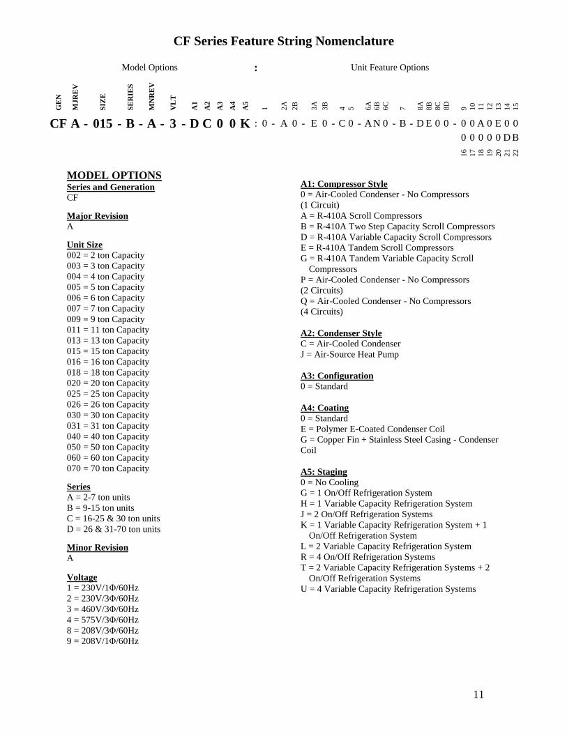
CF Series Feature String Nomenclature
Model Options Unit Feature Options G
EN
MJ
RE
V
SIZ
E
SE
RIE
S
MN
RE
V
VL
T
A1
A2
A3
A4
A5
1
2A
2B
3A
3B
4
5
6A
6B
6C
7
8A
8B
8C
8D
9
10
11
12
13
14
15
CF A - 015 - B - A - 3 - D C 0 0 K 0 - A 0 - E 0 - C 0 - A N 0 - B - D E 0 0 - 0 0 A 0 E 0 0
0 0 0 0 0 D B
16
17
18
19
20
21
22
11
CF Series Feature String Nomenclature
MODEL OPTIONS Series and Generation
CF
Major Revision
A
Unit Size
002 = 2 ton Capacity
003 = 3 ton Capacity
004 = 4 ton Capacity
005 = 5 ton Capacity
006 = 6 ton Capacity
007 = 7 ton Capacity
009 = 9 ton Capacity
011 = 11 ton Capacity
013 = 13 ton Capacity
015 = 15 ton Capacity
016 = 16 ton Capacity
018 = 18 ton Capacity
020 = 20 ton Capacity
025 = 25 ton Capacity
026 = 26 ton Capacity
030 = 30 ton Capacity
031 = 31 ton Capacity
040 = 40 ton Capacity
050 = 50 ton Capacity
060 = 60 ton Capacity
070 = 70 ton Capacity
Series
A = 2-7 ton units
B = 9-15 ton units
C = 16-25 amp 30 ton units
D = 26 amp 31-70 ton units
Minor Revision
A
Voltage
1 = 230V1Φ60Hz
2 = 230V3Φ60Hz
3 = 460V3Φ60Hz
4 = 575V3Φ60Hz
8 = 208V3Φ60Hz
9 = 208V1Φ60Hz
A1 Compressor Style
0 = Air-Cooled Condenser - No Compressors
(1 Circuit)
A = R-410A Scroll Compressors
B = R-410A Two Step Capacity Scroll Compressors
D = R-410A Variable Capacity Scroll Compressors
E = R-410A Tandem Scroll Compressors
G = R-410A Tandem Variable Capacity Scroll
Compressors
P = Air-Cooled Condenser - No Compressors
(2 Circuits)
Q = Air-Cooled Condenser - No Compressors
(4 Circuits)
A2 Condenser Style
C = Air-Cooled Condenser
J = Air-Source Heat Pump
A3 Configuration
0 = Standard
A4 Coating
0 = Standard
E = Polymer E-Coated Condenser Coil
G = Copper Fin + Stainless Steel Casing - Condenser
Coil
A5 Staging
0 = No Cooling
G = 1 OnOff Refrigeration System
H = 1 Variable Capacity Refrigeration System
J = 2 OnOff Refrigeration Systems
K = 1 Variable Capacity Refrigeration System + 1
OnOff Refrigeration System
L = 2 Variable Capacity Refrigeration System
R = 4 OnOff Refrigeration Systems
T = 2 Variable Capacity Refrigeration Systems + 2
OnOff Refrigeration Systems
U = 4 Variable Capacity Refrigeration Systems
CF Series Feature String Nomenclature
Model Options Unit Feature Options G
EN
MJR
EV
SIZ
E
SE
RIE
S
MN
RE
V
VL
T
A1
A2
A3
A4
A5
1
2A
2B
3A
3B
4
5
6A
6B
6C
7
8A
8B
8C
8D
9
10
11
12
13
14
15
CF A - 015 - B - A - 3 - D C 0 0 K 0 - A 0 - E 0 - C 0 - A N 0 - B - D E 0 0 - 0 0 A 0 E 0 0
0 0 0 0 0 D B
16
17
18
19
20
21
22
12
UNIT FEATURE OPTIONS 1 Unit Orientation
0 = Vertical Condenser Discharge - Standard Access
A = Horizontal Condenser Discharge - Standard
Access
2A Refrigeration Control
0 = Standard
A = 5 Minute Compressor Off Timer + 20 Second
Compressor Stage Delay
C = Adjustable Fan Cycling
D = Adjustable Compressor Lockout
G = Option A + Adjustable Fan Cycling
H = Option A + Adjustable Compressor Lockout
M = Adjustable Fan Cycling + Adjustable
Compressor Lockout
W = Option A + Adjustable Fan Cycling +
Adjustable Compressor Lockout
2B Blank
0 = Standard
3A Refrigeration Options
0 = Standard
A = Hot Gas Bypass Lead Stage [HGB]
B = HGB Lead + HGB Lag
D = Hot Gas Bypass Non-Variable Capacity
Refrigeration Systems [HGBNV]
E = Modulating Hot Gas Reheat [MHGR]
H = HGB + MHGR
J = HGB Lead + HGB Lag + MHGR
L = HGBNV + MHGR
3B Blank
0 = Standard
4 Refrigeration Accessories
0 = Standard
A = Sight Glass
B = Compressor Isolation Valves
C = Options A + B
D = Flooded Condenser 0degF Low Ambient Controls ndash
One Circuit
E = Options A + D
F = Options B + D
G = Options A + B + D
H = Flooded Condenser 0degF Low Ambient Controls-
Two Circuits
J = Options A + H
K = Options B + H
L = Options A + B + H
R = Flooded Condenser 0degF Low Ambient Controls ndash
Four Circuits
S = Options A + R
T = Options B + R
U = Options A + B + R
5 Blank
0 = Standard
6A Unit Disconnect Type
0 = Single Point Power Block
A = Single Point Power Non-Fused Disconnect
6B Disconnect 1 Size
0 = Standard
N = 100 amps
R = 150 amps
V = 250 amps
Z = 400 amps
6C Blank
0 = Standard
CF Series Feature String Nomenclature
Model Options Unit Feature Options
GE
N
MJR
EV
SIZ
E
SE
RIE
S
MN
RE
V
VL
T
A1
A2
A3
A4
A5
1
2A
2B
3A
3B
4
5
6A
6B
6C
7
8A
8B
8
C
8D
9
10
11
12
13
14
15
CF A - 015 - B - 0 - 3 - D C 0 0 K 0 - A 0 - E 0 - C 0 - A N 0 - B - D C 0 0 - 0 0 A 0 E 0 0 0 0 0 0 0 D B
16
17
18
19
20
21
22
13
7 Accessories
0 = Standard
B = Phase amp Brown Out Protection
D = Suction Pressure Transducer on Each
Refrigeration Circuit
E = Compressor Sound Blanket
L = Options B + D
M = Options B + E
Q = Options D + E
1 = Options B + D + E
8A Control Sequence
A = Terminal Block for Thermostat w Isolation
Relays
D = VAV Unit Controller - VAV Cool + CAV Heat
E = CAV Unit Controller
F = Makeup Air Unit Controller - CAV Cool + CAV
Heat
H = Constant Volume HP Unit Controller - CAV
Cool + CAV Heat
J = Makeup Air HP Unit Controller - CAV Cool +
CAV Heat
N = Field Installed DDC Controls by Others with
Isolation Relays
8B Control Suppliers
0 = Standard
E = Orion VCC-X (Main Controller in Air Handling
Unit)
H = AAON Touchscreen Controller (Main Controller
in Air Handling Unit)
8C Control Supplier Options
0 = Standard
8D BMS Connection amp Diagnostics
0 = Standard
9 Blank
0 = Standard
10 Blank
0 = Standard
11 Maintenance Accessories
0 = Standard
A = Factory Wired 115VAC Convenience Outlet
B = Field Wired 115VAC Convenience Outlet
C = Service Lights
E = Remote Unit StartStop Terminals
F = Options A + C
H = Options A + E
J = Options B + C
L = Options B + E
N = Options C + E
R = Options A + C + E
U = Options B + C + E
12 Code Options
0 = Standard ETL USA Listing
B = ETL USA + Canada Listing
13 Air-Cooled Condenser Accessories
0 = Standard
A = Condenser Coil Guard
C = ECM Condenser Fan Head Pressure Control
E = VFD Condenser Fan Head Pressure Control
G = Options A + C
J = Options A + E
N = ECM Condenser Fan Head Pressure Control +
Low Sound Condenser Fan
S = Options A + N
14 Blank
0 = Standard
15 Blank
0 = Standard
16 Electrical Options
0 = Standard
17 Shipping Options
0 = Standard
A = Crating
B = Export Crating
CF Series Feature String Nomenclature
Model Options Unit Feature Options G
EN
MJR
EV
SIZ
E
SE
RIE
S
MN
RE
V
VL
T
A1
A2
A3
A4
A5
1
2A
2B
3A
3B
4
5
6A
6B
6C
7
8A
8B
8C
8D
9
10
11
12
13
14
15
CF A - 015 - B - A - 3 - D C 0 0 K 0 - A 0 - E 0 - C 0 - A N 0 - B - D E 0 0 - 0 0 A 0 E 0 0
0 0 0 0 0 D B 1
6
17
18
19
20
21
22
14
18 Blank
0 = Standard
19 Blank
0 = Standard
20 Cabinet Material
0 = Galvanized Steel Cabinet
21 Warranty
0 = Standard
D = Compressor Warranty - Years 2-5
22 Type
B = Premium AAON Gray Paint Exterior
E = Premium AAON Gray Paint Ext + Shrink Wrap
X = SPA + Premium AAON Gray Paint Exterior
1 = SPA + Premium AAON Gray Paint Exterior +
Shrink Wrap
15
General Information
AAON CF Series air-cooled condensers and
condensing units have been designed for
outdoor use only They are factory
assembled wired charged and run-tested
Codes and Ordinances
CF Series units have been tested and
certified by ETL in accordance with UL
Safety Standard 1995CSA C222 No 236
System should be sized in accordance with
the American Society of Heating
Refrigeration and Air Conditioning
Engineers Handbook
Installation of CF Series units must conform
to the ICC standards of the International
Mechanical Code the International Building
Code and local building plumbing and
electrical codes All appliances must be
electrically grounded in accordance with
local codes or in the absence of local codes
the current National Electric Code
ANSINFPA 70 or the current Canadian
Electrical Code CSA C221
Receiving Unit
When received the unit should be checked
for damage that might have occurred in
transit If damage is found it should be noted
on the carrierrsquos freight bill A request for
inspection by carrierrsquos agent should be made
in writing at once Nameplate should be
checked to ensure the correct model sizes and
voltages have been received to match the job
requirements
If repairs must be made to damaged goods
then the factory should be notified before any
repair action is taken in order to protect the
warranty Certain equipment alteration
repair and manipulation of equipment
without the manufacturerrsquos consent may void
the product warranty Contact AAON
Technical Support for assistance with
handling damaged goods repairs and freight
claims (918) 382-6450
SHARP EDGES
Coils and sheet metal surfaces present sharp edges and care must be taken when working with equipment
WARNING
QUALIFIED INSTALLER
Improper installation adjustment alteration service or maintenance can cause property damage personal injury or loss of life Installation and service must be performed by a Factory Trained Service Technician
WARNING
Failure to observe the following instructions will result in premature failure of your system and possible voiding of the warranty
WARNING
16
Storage
If installation will not occur immediately
following delivery store equipment in a dry
protected area away from construction traffic
and in the proper orientation as marked on the
packaging with all internal packaging in
place Secure all loose-shipped items
Failure to observe the following instructions
will result in premature failure of your
system and possible voiding of the warranty
Never turn off the main power supply to the
unit except for complete shutdown When
power is cut off from the unit any
compressors using crankcase heaters cannot
prevent refrigerant migration This means the
compressor will cool down and liquid
refrigerant may accumulate in the
compressor The compressor is designed to
pump refrigerant gas and damage may occur
if liquid enters the compressor when power is
restored
Before unit operation the main power switch
must be turned on for at least twenty-four
hours for units with compressor crankcase
heaters This will give the crankcase heater
time to clear any liquid accumulation out of
the compressor before it is required to run
Always control the system from the control
panel never at the main power supply (except
for emergency or for complete shutdown of
the system)
CLEAN AIR ACT
The Clean Air Act of 1990 bans the intentional venting of refrigerant as of July 1 1992 Approved methods of recovery recycling or reclaiming must be followed
CAUTION
CRANKCASE HEATER OPERATION
Units are equipped with compressor crankcase heaters which should be energized at least 24 hours prior to cooling operation to clear any liquid refrigerant from the compressors
CAUTION
3-PHASE ROTATION
Rotation must be checked on all MOTORS AND COMPRESSORS of three phase units All motors to include and not be limited to pump motors and condenser fan motors should all be checked by a qualified service technician at startup and any wiring alteration should only be made at the unit power connection
CAUTION
17
The standard compressors must be on a
minimum of 5 minutes and off for a minimum
of 5 minutes The cycle rate must be no more
than 6 starts per hour
The variable capacity compressors must be
on a minimum of 3 minutes and off for a
minimum of 3 minutes The cycle rate must
be no more than 6 starts per hour
The compressor life will be seriously
shortened by reduced lubrication and the
pumping of excessive amounts of liquid oil
and liquid refrigerant
Wiring Diagrams
A complete set of unit specific wiring
diagram in point-to-point form is laminated
in plastic and located inside the control
compartment door
General Maintenance
When the initial startup is made and on a
periodic schedule during operation it is
necessary to perform routine service checks
on the performance of the condensing unit
This includes reading and recording suction
pressures and checking for normal sub-
cooling and superheat
COMPRESSOR ROTATION
Scroll compressors are directional and will be damaged by operation in the wrong direction Low pressure switches on compressors have been disconnected after factory testing Rotation should be checked by a qualified service technician at startup using suction and discharge pressure gauges and any wiring alteration should only be made at the unit power connection
COMPRESSOR CYCLING
5 MINUTE MINIMUM OFF TIME To prevent motor overheating compressors must cycle off for a minimum of 5 minutes
5 MINUTE MINIMUM ON TIME To maintain the proper oil level compressors must cycle on for a minimum of 5 minutes The cycle rate must not exceed 6 starts per hour
WARNING
CAUTION
18
Installation
Forklifting the Unit
CF Series condensing unit sizes 2-25 amp 30
tons can be lifted using a forklift 2-7 ton
units must have forks at least 48rdquo in length
9-25 amp 30 ton units must have forks 72rdquo in
length or the forks must have 72rdquo fork
extensions Standard units can be lifted from
all sides except the condenser coil side CF
Series condensing unit sizes 26 amp 31-70 tons
cannot be lifted using a forklift They can be
lifted as shown in Figure 3
Forks must be perpendicular to the unit and
they must be in far enough that the back of
the forks are no more than 6rdquo away from the
edge of the unit
Figure 1 - Forklifting a CF Series A Cabinet
Figure 2 - Forklifting a CF Series B and C
Cabinet
FORKLIFTING 2-7 TON UNITS
Forks or Fork Extensions must be at least 48rdquo in length
CAUTION
FORKLIFTING 9-25 amp 30 TON UNITS
Forks or Fork Extensions must be at least 72rdquo in length
CAUTION
19
Lifting the Unit
If cables or chains are used to hoist the unit
they must be the same length Minimum
cable length is 99rdquo for CF Series 9-70 ton
units CF Series 2-7 ton units do not include
factory installed lifting lugs and should be
lifted by forklift only Care should be taken
to prevent damage to the cabinet coils and
condenser fans
Before lifting unit be sure that all shipping
material has been removed from unit Secure
hooks and cables at all lifting points lugs
provided on the unit
Figure 3 ndash Lifting Details and Orientation of
a CF Series 9-70 ton Condensing Unit
Locating the Unit
The CF Series condenser and condensing unit
is designed for outdoor applications and
mounting at ground level or on a rooftop It
must be placed on a level and solid
foundation that has been prepared to support
its weight When installed at ground level a
one-piece concrete slab should be used with
footings that extend below the frost line Also
with ground level installation care must be
taken to protect the coil fins from damage due
to vandalism or other causes
The first clearance table below gives the
clearance values for proper unit operation
The second clearance table gives the
clearance necessary for removing the coil
without disassembling a large part of the
condensing unit For ease of removing the
condenser coil use the second table
clearances for the right hand side of the unit
Table 1 ndashClearances for Proper Operation
Location Unit Size
2-7 tons 9-70 tons
Front -
(Controls
Side)
Unobstructed 36rdquo
Left Side 6rdquo 30rdquo
Right Side 6rdquo 36rdquo
Top 3rdquo Unobstructed
Back 18rdquo 6rdquo
Table 2 ndash Clearances for Coil Pull
Unit Size Right Hand Side
2-7 tons 42rdquo
9-15 tons 42rdquo
16-25 amp 30 tons 54rdquo
26 amp 31-70 tons 66rdquo
Figure 4 - Orientation of Series 2-7 ton
Condensing Unit
20
The placement relative to the building air
intakes and other structures must be carefully
selected Airflow to and from the condenser
or condensing unit must not be restricted to
prevent a decrease in performance and
efficiency
The installation position for 9-70 ton units
must provide at least 30rdquo of left and right side
clearance for proper airflow to the condenser
coils When units are mounted adjacent to
each other the minimum right and left side
clearance required between the units is 60rdquo or
5 feet Similarly when 2-7 ton units are
mounted adjacent to each other the minimum
clearance required between the back side of
the units is 36rdquo or 3 feet
Units should not be installed in an enclosure
or pit that is deeper than the height of the unit
When recessed installation is necessary the
clearance to maintain proper airflow is at
least 5 feet (3 feet for 2-7tons)
CF Series condensers and condensing units
that have a vertical air discharge must have
no obstruction above the equipment Do not
place the unit under an overhang CF Series
condensers and condensing units that have a
horizontal discharge must have no
obstruction in front of the unit
For proper unit operation the immediate area
around condenser must remain free of debris
that may be drawn in and obstruct airflow in
the condensing section
Consideration must be given to obstruction
caused by snow accumulation when placing
the unit
Mounting Isolation
For roof mounted applications or anytime
vibration transmission is a factor vibration
isolators may be used
Access Doors
Access doors are provided to the compressor
and electrical compartment
Standard Evacuation Instructions
Proper system evacuation is critical to
remove moisture and non-condensables from
the system before charging the system with
refrigerant A newly installed AAON
condensing unit has already been evacuated
and charged with some refrigerant at the
factory When evacuating a new system
keep the condensing unit service valves
closed and evacuate the suction and liquid
lines and the air handling unit If the entire
system must be evacuated use the following
procedure to ensure the entire system is
pulled into a good vacuum
1 System evacuation should be
performed anytime a system is open to
atmospheric pressure The POE oils
used with R-410A are extremely
hydroscopic in nature and immediately
begin pulling in moisture once the
system is opened to the atmosphere
2 Before starting to evacuate the
system you MUST ensure that there are
no leaks by pressurizing the system with
PVC PIPING
PVC (Polyvinyl Chloride) and CPVC (Chlorinated Polyvinyl Chloride) are vulnerable to attack by certain chemicals Polyolester (POE) oils used with R-410A and other refrigerants even in trace amounts in a PVC or CPVC piping system will result in stress cracking of the piping and fittings and complete piping system failure
CAUTION
21
400 psig of dry nitrogen and verifying no
pressure loss after one hour
3 Four valve manifold gauge sets are
more effective than standard manifold
gauge sets due to the extra hose port in
combination with a 38rsquorsquo evacuation
port The larger diameter evacuation port
will expedite system evacuation
4 The manifold set should be connected
to the condensing unit with one hose on
the suction line service valve one hose
on the liquid line service valve and if an
extra Schrader valve is field installed on
the suction line connect a third hose (not
shown) The vacuum pump should be
connected to the manifold set using a
38rdquo vacuum rated hose Figure 5 shows
two circuits Both circuits must be
evacuated separately
Figure 5 ndash CU evacuation connections
5 An accurate micron gauge must be
used and checked by pulling a vacuum
on the gauge by itself and verify a rapid
drop to less than 100 microns within a
few minutes
6 The micron gauge should not be
attached to the system until the gauge
manifold is reading 28rsquorsquo of vacuum to
ensure the micron gauge does not see
pressure and is thus damaged MICRON
GAUGES WILL BE DAMAGED BY
PRESSURE
7 It is a good practice to replace the
vacuum pump oil after one hour of the
evacuation process The oil can be
broken down in the pump in the initial
first hour causing system evacuation to
take longer than it should
8 The minimum micron level required
by AAON is 350 microns for systems
using POE oils
9 The system should then be isolated
and the pump turned off to check for
vacuum rise due to leaks or moisture in
the system The micron gauge should
not rise above 500 microns after 30
minutes of wait time
Low Ambient amp Modulating Reheat
System Evacuation Instructions
Proper system evacuation is critical to
remove moisture and non-condensables from
the system before charging the system with
refrigerant Systems with low ambient
flooded condenser option require the
following procedure to ensure the entire
system is pulled into a good vacuum
1 System evacuation should be
performed anytime a system is open to
atmospheric pressure The POE oils
used with R-410A are extremely
hydroscopic in nature and immediately
begin pulling in moisture once the
system is opened to the atmosphere
2 Open the reheat valve to 50 when
evacuating
3 Before starting to evacuate the
system you MUST ensure that there are
no leaks by pressurizing the system with
22
400 psig of dry nitrogen and verifying no
pressure loss after one hour
4 Four valve manifold gauge sets are
more effective than standard manifold
gauge sets due to the extra hose port in
combination with a 38rsquorsquo evacuation
port The larger diameter evacuation port
will expedite system evacuation
5 The manifold set should be connected
to the condensing unit with one hose on
the suction line service valve one hose
on the liquid line service valve and a
third hose on the reheat line service
valve The vacuum pump should be
connected to the manifold set using a
38rdquo vacuum rated hose Figure 6 shows
two circuits The first circuit has a
reheat line the second circuit is just the
suction and liquid line Both circuits
must be evacuated separately
Figure 6 ndash CU evacuation connections
6 FAILURE to connect to the liquid
line service valve will result in the
receiver tank not being fully evacuated
and most likely lead to non-
condensables in the system
7 An accurate micron gauge must be
used and checked by pulling a vacuum
on the gauge by itself and verify a rapid
drop to less than 100 microns within a
few minutes
8 The micron gauge should not be
attached to the system until the gauge
manifold is reading 28rsquorsquo of vacuum to
ensure the micron gauge does not see
pressure and is thus damaged MICRON
GAUGES WILL BE DAMAGED BY
PRESSURE
9 It is a good practice to replace the
vacuum pump oil after one hour of the
evacuation process The oil can be
broken down in the pump in the initial
first hour causing system evacuation to
take longer than it should
10 The minimum micron level required
by AAON is 350 microns for systems
using POE oils
11 The system should then be isolated
and the pump turned off to check for
vacuum rise due to leaks or moisture in
the system The micron gauge should
not rise above 500 microns after 30
minutes of wait time
Adjusting Refrigerant Charge
All AAON CF Series condensers and
condensing units are shipped with a factory
holding charge The factory charge is
different depending on the unit size and
system (heat pump modulating hot gas
reheat LAC) The factory charge per circuit
is shown on the unit nameplate Adjusting the
charge of the system will be required during
installation
23
Adjusting the charge of a system in the field
must be based on determination of liquid sub-
cooling and evaporator superheat On a
system with a thermostatic expansion valve
liquid sub-cooling is more representative of
the charge than evaporator superheat but both
measurements must be taken
Before Charging
Refer to the Unit Nameplate to determine
which refrigerant must be used to charge the
system
Unit being charged must be at or near full
load conditions before adjusting the charge
Units equipped with hot gas bypass must
have the hot gas bypass valve closed to get
the proper charge
Units equipped with hot gas reheat must be
charged with the hot gas valve closed while
the unit is in cooling mode After charging
unit should be operated in reheat
(dehumidification) mode to check for correct
operation
Units equipped with heat pump options
should be charged in cooling mode to get the
proper charge After charging unit should be
operated in heating mode to check for correct
charge Charge may need to be adjusted for
heating mode If adjustments are made in the
heating mode cooling mode must be rerun to
verify proper operation
After adding or removing charge the system
must be allowed to stabilize typically 10-15
minutes before making any other
adjustments
The type of unit and options determine the
ranges for liquid sub-cooling and evaporator
superheat Refer to Table 3 when determining
the proper sub-cooling
For units equipped with low ambient (0degF)
option see the special charging instructions at
the end of this section
Checking Liquid Sub-cooling
Measure the temperature of the liquid line as
it leaves the condenser coil
Read the gauge pressure at the liquid line
close to the point where the temperature was
taken You must use liquid line pressure as it
will vary from discharge pressure due to
condenser coil pressure drop
Convert the pressure obtained to a saturated
temperature using the appropriate refrigerant
temperature-pressure chart
COMPRESSOR LUBRICANT
Polyolester (POE) and Polyvinylether (PVE) oils are two types of lubricants used in hydrofluorocarbon (HFC) refrigeration systems Refer to the compressor label for the proper compressor lubricant type
CAUTION
CLEAN AIR ACT
The Clean Air Act of 1990 bans the intentional venting of refrigerant (CFCrsquos and HCFCrsquos) as of July 1 1992 Approved methods of recovery recycling or reclaiming must be followed Fines andor incarceration may be levied for non-compliance
CAUTION
24
Subtract the measured liquid line temperature
from the saturated temperature to determine
the liquid sub-cooling
Compare calculated sub-cooling to Table 3
for the appropriate unit type and options
Table 3 - Acceptable Refrigeration Circuit
Values
Cooling
Mode
Liquid Sub-
Cooling
Values
Cooling Only Unit4 8-15degF
Cooling Only Unit with Hot
Gas Reheat14 5-15degF
Heat PumpUnit24 2-4degF
Heat Pump Unit with Hot
Gas Reheat34 2-6degF
Cooling Only Unit with
LAC4 8-15degF
Cooling Only Unit with Hot
Gas Reheat amp LAC4 8-15degF
Notes 1 Must be charged with the hot gas valve
closed After charging unit should be
operated in reheat (dehumidification) mode
to check for correct operation
2 The sub-cooling value in this table is for the
unit running in cooling mode of operation
After charging unit should be operated in
heating mode to check for correct operation
3 The sub-cooling value in this table is for the
unit running in cooling mode of operation
and the hot gas valve closed After charging
unit should be operated in reheat
(dehumidification) mode to check for correct
operation and then in heating mode to check
for correct operation
4 Sub-cooling must be increased by 1degF per 10
feet of vertical liquid line rise for R-410A
(AHU above CU) For example a cooling
only unit with hot gas reheat and a vertical
liquid drop can charge to a sub-cooling value
of 5-15degF but a cooling only unit with hot
gas reheat and a vertical liquid rise of 30 ft
must charge to a sub-cooling value of at least
8-15degF DO NOT OVERCHARGE
Refrigerant overcharging leads to excess
refrigerant in the condenser coils resulting in
elevated compressor discharge pressure
Checking Evaporator Superheat
Measure the temperature of the suction line
close to the compressor
Read gauge pressure at the suction line close
to the compressor
Convert the pressure obtained to a saturated
temperature using the appropriate refrigerant
temperature-pressure chart
Subtract the saturated temperature from the
measured suction line temperature to
determine the evaporator superheat
For refrigeration systems with tandem
compressors it is critical that the suction
superheat setpoint on the TXV is set with one
compressor running The suction superheat
should be 10-13degF with one compressor
running The suction superheat will increase
with both compressors in a tandem running
Inadequate suction superheat can allow liquid
refrigerant to return to the compressors which
will wash the oil out of the compressor Lack
of oil lubrication will destroy a compressor
Liquid sub-cooling should be measured with
both compressors in a refrigeration system
running
Compare calculated superheat to the
acceptable cooling mode superheat values of
8-15degF for all system types Superheat will
increase with long suction line runs
25
Adjusting Sub-cooling and Superheat
Temperatures
The system is overcharged if the sub-cooling
temperature is too high compared to Table 3
and the evaporator is fully loaded (low loads
on the evaporator result in increased sub-
cooling) and the evaporator superheat is
within the temperature range of 8-15degF (high
superheat results in increased sub-cooling)
Correct an overcharged system by reducing
the amount of refrigerant in the system to
lower the sub-cooling
The system is undercharged if the superheat
is too high and the sub-cooling is too low
Correct an undercharged system by adding
refrigerant to the system to reduce superheat
and raise sub-cooling
If the sub-cooling is correct and the superheat
is too high the TXV may need adjustment to
correct the superheat
DO NOT OVERCHARGE Refrigerant overcharging leads to excess refrigerant in the condenser coils resulting in elevated compressor discharge pressure
CAUTION
EXPANSION VALVE ADJUSTMENT
Thermal expansion valves must be adjusted to approximately 8-15degF of suction superheat Failure to have sufficient superheat will damage the compressor and void the warranty
CAUTION
26
Special Low Ambient Option Charging
Instructions
For units equipped with low ambient
refrigerant flood back option being charged
in the summer when the ambient
temperature is warm
If the ambient is above 70degF charge to
approximately 1-2degF of sub-cooling
measured at the inlet to the expansion valve
Once enough charge has been added to get
the evaporator superheat and sub-cooling
values to the correct setting more charge
must be added Use Table 4 to find the
additional charge amount required for the
system when running in cold ambient
conditions
Table 4 ndash Charge to Flood Condenser Coil
for Ambient Above 70degF
CF Size of
circuits
Per Circuit
Charge (lbs)
CF 2 3 1 49
CF 4 5 6 7 1 92
CF 9 11 2 91
CF 13 15 2 121
CF 16 18 2 131
CF 20 25 30 2 175
CF 26 31 40 2 180
4 91
CF 50 60 70 2 438
4 221
For units equipped with low ambient
refrigerant flood back option being charged
in the winter when the ambient
temperature is cold
1 If the ambient is below 70degF charge
to approximately 1-2degF of sub-cooling
measured at the inlet to the expansion
valve Once enough charge has been
added to get the evaporator superheat
and sub-cooling values to the correct
setting more charge may need to be
added If the ambient temperature is 0degF
no more charge is required Ambient
temperatures above 0degF will require a
percentage of the per circuit charge
values from Table 4 Using your
ambient temperature find the
percentage value from Table 5 and
multiply the Per Circuit Charge value
from Table 4 and the value to
determine the additional charge amount
Table 5 ndash Charge to Flood Condenser
Coil for Ambient Below 70degF
Condenser
Ambient
Temperature ˚F
Percentage
Per Circuit
Charge from
Table 4
60 60
50 37
40 24
30 15
20 8
0 0
2 The unit should be checked for proper
operation once the ambient temperature
is above 80degF
Example A CF size 31 with tandem
compressors where the ambient
temperature is 40degF
From Table 4 ndash 18 lbs refrigerant charge
per circuit (tandem compressors would
have 2 circuits in this size of CF)
From Table 5 ndash 24 of Table 4 charge
Additional charge needed for a unit with
low ambient flooded condenser controls
= 18 lbs 024 = 432 lbs additional
refrigerant charge per circuit
27
Low Ambient Operation
During low ambient temperatures the vapor
refrigerant will migrate to the cold part of the
system and condense into liquid All CF
Series compressors are provided with factory
installed crankcase heaters to help prevent
liquid refrigerant from slugging the
compressors during startup in low ambient
conditions The condenser or condensing unit
must have continuous power 24 hours prior
to startup This ensures the compressor will
receive sufficient refrigerant vapor at startup
Standard units can operate down to 55degF
ambient temperature
AAON condenser fan head pressure control
units can operate down to 35degF ambient
temperature Three different condenser fan
head pressure control options available are
adjustable fan cycling ECM condenser fan
or VFD controlled condenser fans See
detailed information following
The AAON low ambient (condenser flood-
back) system is used to operate a refrigerant
system down to 0degF outside air temperature
See detailed information following
Fan Cycling Low Ambient
Adjustable fan cycling is a low ambient head
pressure control option that cycles the
condenser fans to maintain refrigerant circuit
head pressures at acceptable levels during
cooling operation The head pressure set
point (100-470 psi) and pressure differential
(35-200 psi) can be field adjusted using a
flathead screwdriver For example if the
head pressure is set to 300psi and the
differential is set to 100psi then fans will cut
in at 300psi and cut out at 200psi Fan
cycling and variable speed condenser fan
head pressure control options allow
mechanical cooling with ambient
temperatures down to 35degF
Figure 7 - Adjustable Fan Cycling Switch
Variable Speed Low Ambient
Variable speed condenser fan head pressure
control is a low ambient head pressure
control option that sends a variable signal in
relation to the refrigerant circuit head
pressure of the system to an electronically
commutated motor (ECM) or VFD The
motor either speeds up or slows down air
flow accordingly in order to maintain
constant head pressure Fan cycling and
variable speed condenser fan head pressure
control options allow mechanical cooling
with ambient temperatures down to 35degF
Flooded Condenser Low Ambient
Flooded condenser low ambient control
maintains normal head pressure during
periods of low ambient When the ambient
temperature drops the condensing
temperature and therefore pressure drops
Without ambient control the system would
shut down on low discharge pressure The
flooded condenser method of low ambient
control fills the condenser coil with liquid
refrigerant decreasing the heat transfer
capacity of the coil which allows the coil to
operate at an acceptable discharge pressure
28
The condenser coil will not be flooded during
summer ambient temperatures so a receiver
is included to store the additional liquid
refrigerant required to flood the condenser
coil in low ambient The receiver is factory-
sized to contain all of the flooded volume
Without a receiver there would be high head
pressures during higher ambient conditions
The low ambient system maintains normal
head pressure during periods of low ambient
by restricting liquid flow from the condenser
to the receiver and at the same time
bypassing hot gas around the condenser to the
inlet of the receiver This reduces liquid
refrigerant flow from the condenser reducing
its effective surface area which in turn
increases the condensing pressure At the
same time the bypassed hot gas raises liquid
pressure in the receiver allowing the system
to operate properly CF Series condensers
and condensing units use an LAC valve for
low ambient operation
LAC Valve
The Low Ambient Control (LAC) valve is a
non-adjustable three way valve that
modulates to maintain receiver pressure As
the receiver pressure drops below the valve
setting (295 psig for R-410A) the valve
modulates to bypass discharge gas around the
condenser The discharge gas warms the
liquid in the receiver and raises the pressure
to the valve setting The following schematic
shows an example system using the LAC
valve
Figure 8 ndash LAC Piping Example
29
Refrigerant Piping
(See back of the manual for refrigerant piping
diagrams)
General
Piping from the condensing unit to the air
handler is the responsibility of the installing
contractor
Use only clean type ldquoACRrdquo copper tubing
that has been joined with high temperature
brazing alloy
The pipe or line sizes must be selected to
meet the actual installation conditions and
NOT simply based on the connection sizes at
the condensing unit or air handler
All CF Series condensing units are provided
with in-line shutoff valves on both the liquid
and suction lines These should remain closed
until the system is ready for start-up after
installation
Piping should conform to generally accepted
practices and codes
Care must be taken not to cross the circuits
on multiple circuit systems
Upon completion of piping connection the
interconnecting piping and air handler MUST
BE evacuated to 500 microns or less leak
checked and charged with refrigerant
Determining Refrigerant Line Size
The piping between the condenser and low
side must ensure
1 Minimum pressure drop and
2 Continuous oil return and
3 Prevention of liquid refrigerant slugging
or carryover
Minimizing the refrigerant line size is
favorable from an economic perspective
reducing installation costs and reducing the
potential for leakage However as pipe
diameters decrease pressure drop increases
Excessive suction line pressure drop causes
loss of compressor capacity and increased
power usage resulting in reduced system
efficiency Excessive pressure drops in the
liquid line can cause the liquid refrigerant to
flash resulting in faulty TXV operation and
improper system performance In order to
operate efficiently and cost effectively while
avoiding malfunction refrigeration systems
must be designed to minimize both cost and
pressure loss
REFRIGERANT PIPING
Line sizes must be selected to meet actual installation conditions not simply based on the connection sizes at the condensing unit or air handling unit
CAUTION
REFRIGERANT PIPING
This section is for information only and is not intended to provide all details required by the designer or installer of the refrigerant piping between the condenser or condensing unit and the air handling unit AAON Inc is not responsible for interconnecting refrigerant piping Consult ASHRAE Handbook ndash Refrigeration and ASME Standards
CAUTION
30
Equivalent Line Length
All line lengths discussed in this manual
unless specifically stated otherwise are
Equivalent Line Lengths The frictional
pressure drop through valves fittings and
accessories is determined by establishing the
equivalent length of straight pipe of the same
diameter Always use equivalent line
lengths when calculating pressure drop
Special piping provisions must be taken
when lines are up vertical risers or in
excessively long line runs AAON does not
recommend running underground
refrigerant lines
Liquid Line
When sizing the liquid line it is important to
minimize the refrigerant charge to reduce
installation costs and improve system
reliability This can be achieved by
minimizing the liquid line diameter
However reducing the pipe diameter will
increase the velocity of the liquid refrigerant
which increases the frictional pressure drop
in the liquid line and causes other
undesirable effects such as noise
Maintaining the pressure in the liquid line is
critical to ensuring sufficient saturation
temperature avoiding flashing upstream of
the TXV and maintaining system efficiency
Pressure losses through the liquid line due to
frictional contact installed accessories and
vertical risers are inevitable Maintaining
adequate sub-cooling at the condenser to
overcome these losses is the only method to
ensure that liquid refrigerant reaches the
TXV
Liquid refrigerant traveling upwards in a riser
loses head pressure If the evaporator is
below the condenser with the liquid line
flowing down the gravitational force will
increase the pressure of the liquid refrigerant
This will allow the refrigerant to withstand
greater frictional losses without the
occurrence of flashing prior to the TXV
A moisture-indicating sight glass may be
field installed in the liquid line to indicate the
occurrence of premature flashing or moisture
in the line The sight glass should not be used
to determine if the system is properly
charged Use temperature and pressure
measurements to determine liquid sub-
cooling not the sight glass
Liquid Line Routing
Care should be taken with vertical risers
When the system is shut down gravity will
pull liquid down the vertical column and
back to the condenser when it is below the
evaporator This could potentially result in
compressor flooding A check valve can be
installed in the liquid line where the liquid
column rises above the condenser to prevent
this The liquid line is typically pitched along
with the suction line or hot gas line to
minimize the complexity of the
configuration
Liquid Line Insulation
In cooling only systems when the liquid line
is routed through regions where temperature
losses are expected no insulation is required
as this may provide additional sub-cooling to
the refrigerant When routing the liquid line
through high temperature areas insulation of
the line is appropriate to avoid loss of sub-
cooling through heat gain
In heat pump systems when the liquid line is
routed through regions where temperature
losses are expected (all lines exposed to
outside air conditions) insulate with a
minimum 1 inch thick Armaflex insulation
as this will prevent capacity loss during
heating mode of operation
31
Liquid Line Guidelines
In order to ensure liquid at the TXV the sum
of frictional losses and pressure loss due to
vertical rise must not exceed available sub-
cooling A commonly used guideline to
consider is a system design with pressure
losses due to friction through the line not to
exceed a corresponding 1-2degF change in
saturation temperature An additional
recommendation is that the sum of frictional
losses (including valve losses filter drier
losses other accessories and line losses) and
pressure loss due to vertical rise should not
exceed 8degF if the available sub-cooling is
10degF
If the velocity of refrigerant in the liquid line
is too great it could cause excessive noise or
piping erosion The recommended maximum
velocities for liquid lines are 100 fpm from
the condenser to a receiver to discourage
fluid backup and 500 fpm from receiver tank
to the evaporator (300 fpm if the line includes
an electric valve to minimize valve induced
liquid hammer)
Liquid Line Accessories
Liquid line shut off valves and filter driers are
factory provided The total length equivalent
of pressure losses through valves elbows and
fittings must be considered when adding
additional components in the field It is a
good practice to utilize the fewest elbows that
will allow the mating units to be successfully
joined
A liquid line receiver is factory installed on
units with modulating hot gas reheat units
with low ambient control flooded condenser
and units with heat pump
Suction Line
The suction line is more critical than the
liquid line from a design and construction
standpoint More care must be taken to
ensure that adequate velocity is achieved to
return oil to the compressor at minimum
loading conditions However reducing the
piping diameter to increase the velocity at
minimal load can result in excessive pressure
losses capacity reduction and noise at full
load
Suction Line Routing
For cooling only systems pitch the suction
line in the direction of flow (about 1 inch per
20 feet of length) to maintain oil flow
towards the compressor and keep it from
flooding back into the evaporator
For heat pump systems do not pitch lines
since they will be flowing in one direction in
cooling mode and the opposite direction in
heating mode
Crankcase heaters are provided to keep any
condensed refrigerant that collects in the
compressor from causing damage or wear
Make sure to provide support to maintain
suction line positioning and insulate
completely between the evaporator and
condensing unit
It is important to consider part load operation
when sizing suction lines At minimum
capacity refrigerant velocity may not be
adequate to return oil up the vertical riser
Decreasing the diameter of the vertical riser
will increase the velocity but also the
frictional loss
For difficult line routing applications a
double suction riser can be applied to the
situation of part load operation with a suction
riser A double suction riser is designed to
return oil at minimum load while not
incurring excessive frictional losses at full
load A double suction riser consists of a
small diameter riser in parallel with a larger
diameter riser and a trap at the base of the
large riser At minimum capacity refrigerant
velocity is not sufficient to carry oil up both
32
risers and it collects in the trap effectively
closing off the larger diameter riser and
diverting refrigerant up the small riser where
velocity of the refrigerant is sufficient to
maintain oil flow At full load the mass flow
clears the trap of oil and refrigerant is carried
through both risers The smaller diameter
pipe should be sized to return oil at minimum
load while the larger diameter pipe should be
sized so that flow through both pipes
provides acceptable pressure drop at full
load
Figure 9 - Double Suction Riser
Construction
A double riser can also be used for heat pump
operation The specific volume (ft3lb) of
refrigerant at the discharge temperature and
pressure (heating mode line conditions) is
significantly lower than the specific volume
at the suction temperature and pressure
(cooling mode line conditions) To
compound the issue the capacity in heating
mode is lower than the capacity in cooling
mode The discharge velocity in the riser
during heating mode is much lower than the
suction velocity during cooling mode Often
a double riser is necessary to get acceptable
velocities for the discharge mode and
acceptable velocities for the suction mode In
the example diagrams (See Figure 10 amp
Figure 11) the cooling mode will use both
lines and the heating mode will use only one
Suction Line Traps
Include a trap immediately after the
evaporator coil outlet to protect the TXV bulb
from liquid refrigerant
Include traps every 20 feet in vertical suction
riser sections for cooling only systems and
every 12 feet for heat pump systems
Suction Line Insulation
The entire suction line should be insulated
with a minimum 1 inch thick Armaflex
insulation This prevents condensation from
forming on the line and reduces any potential
loss in capacity associated with heat gain
placing additional load on the system This
line should still be insulated in heat pump
systems even though it acts as both a
discharge and suction line
Suction Line Guidelines
For proper performance suction line
velocities less than a 4000 fpm maximum are
recommended The minimum velocity
required to return oil is dependent on the pipe
diameter however a general guideline of
1000 fpm minimum may be applied
When suction flow is up variable capacity
compressors require a minimum velocity of
1500 fpm at full load
Tandem compressors must be considered for
full load operation (both compressors
operating) and at partial load (only one
compressor operating) When suction flow is
up and the tandem has a variable capacity
compressor the velocity for only one
compressor in operation must be greater than
1500 fpm For onoff compressors the
velocity must be greater than the minimum
velocity required to return oil
Heat pump vapor lines must be checked for
suction flow (cooling mode operation) and
discharge flow (heating mode operation)
33
The same line must be used for both modes
of operation
In a fashion similar to the liquid line a
common guideline to consider is a system
design with pressure losses due to friction
through the line not to exceed a
corresponding 1-2degF change in saturation
temperature
For split system piping with long horizontal
runs and short vertical risers a smaller pipe
size can be used to provide sufficient velocity
to return oil in vertical risers at part loads and
a larger size pipe can be used on the
horizontal runs and vertical drop sections
This helps with oil return yet keeps the
pressure drop to a minimum
Suction Line Accessories
If the job requirements specify suction
accumulators they must be separately
purchased and field installed Heat pump
units will include a factory installed suction
accumulator
Discharge Line
The discharge line is similar to the suction
line from a design and construction
standpoint Care must be taken to ensure that
adequate velocity is achieved to return oil to
the compressor at minimum loading
conditions However reducing the piping
diameter to increase the velocity at minimal
load can result in excessive pressure losses
capacity reduction and noise at full load
Pressure loss in the discharge line has less of
an impact on capacity than pressure loss in
the suction line Pressure loss in the
discharge line causes the compressors to
work harder and thus use more power
Discharge Line Routing
For cooling only remote condenser systems
pitch the discharge line in the direction of
flow (about 1 inch per 20 feet of length) to
maintain oil flow towards the compressor
In a heat pump system the field installed
suction line is also used as a discharge line in
the heating mode of operation so the line
must be sized to meet both the suction line
conditions in cooling mode and the discharge
line conditions in heating mode
Because it is used in both directions for a heat
pump unit the line should be installed level
not pitched to facilitate oil return in both
modes of operation
It is important to consider part load operation
when sizing discharge lines At minimum
capacity refrigerant velocity may not be
adequate to return oil up the vertical riser
Decreasing the diameter of the vertical riser
will increase the velocity but also the
frictional loss
For difficult line routing applications a
double discharge riser can be applied to the
situation of part load operation with a
discharge riser A double discharge riser is
designed to return oil at minimum load while
not incurring excessive frictional losses at
full load A double discharge riser consists of
a small diameter riser in parallel with a larger
diameter riser and a trap at the base of the
large riser At minimum capacity refrigerant
velocity is not sufficient to carry oil up both
risers and it collects in the trap effectively
closing off the larger diameter riser and
diverting refrigerant up the small riser where
SUCTION RISER TRAPS
Circuits require suction riser traps every 20 feet (every 12 feet for heat pumps)
CAUTION
34
velocity of the refrigerant is sufficient to
maintain oil flow At full load the mass flow
clears the trap of oil and refrigerant is carried
through both risers The smaller diameter
pipe should be sized to return oil at minimum
load while the larger diameter pipe should be
sized so that flow through both pipes
provides acceptable pressure drop at full
load (See the Double Suction Riser
Construction Figure 9)
A double riser can also be used for heat pump
operation The specific volume (ft3lb) of
refrigerant at the discharge temperature and
pressure (heating mode line conditions) is
significantly lower than the specific volume
at the suction temperature and pressure
(cooling mode line conditions) To
compound the issue the capacity in heating
mode is lower than the capacity in cooling
mode The discharge velocity in the riser
during heating mode is much lower than the
suction velocity during cooling mode Often
a double riser is necessary to get acceptable
velocities for the discharge mode and
acceptable velocities for the suction mode In
the example diagrams the cooling mode will
use both lines and the heating mode will use
only one See the following schematics that
illustrate how the double discharge riser can
work for heat pump applications
Figure 10 ndash Heat Pump Piping Schematic of
Cooling Mode in Double Riser
Figure 11 ndash Heat Pump Piping Schematic of
Heating Mode in Double Riser
35
Discharge Line Traps
Include traps every 12 feet in vertical
discharge riser sections
Discharge Line Insulation
Although a typical discharge line does not
need to be insulated the suction line does
Since the same line is used for both the line
must be insulated as described in the Suction
Line Insulation section
Discharge Line Guidelines
For proper performance discharge line
velocities less than a 3500 fpm maximum are
recommended The minimum velocity
required to return oil is dependent on the pipe
diameter however a general guideline of
900 fpm minimum may be applied
When discharge flow is up variable capacity
compressors require a minimum velocity of
900 fpm at full load
Tandem compressors must be considered for
full load operation (both compressors
operating) and at partial load (only one
compressor operating) When discharge flow
is up and the tandem has a variable capacity
compressor the velocity for only one
compressor in operation must be greater than
900 fpm For onoff compressors the
velocity must be greater than the minimum
velocity required to return oil
Heat pump vapor lines must be checked for
suction flow (cooling mode operation) and
discharge flow (heating mode operation)
The same line must be used for both modes
of operation
In a fashion similar to the suction line a
common guideline to consider is a system
design with pressure losses due to friction
through the line not to exceed a
corresponding 1-2degF change in saturation
temperature
For split system piping with long horizontal
runs and short vertical risers a smaller pipe
size can be used to provide sufficient velocity
to return oil in vertical risers at part loads and
a larger size pipe can be used on the
horizontal runs and vertical drop sections
This helps with oil return yet keeps the
pressure drop to a minimum
Hot Gas Bypass Line
Hot Gas Bypass is available for use with DX
systems that may experience low suction
pressure during the operating cycle This may
be due to varying load conditions associated
with VAV applications or units supplying a
large percentage of outside air The system is
designed to divert refrigerant from the
compressor discharge to the low pressure
side of the system in order to keep the
evaporator from freezing and to maintain
adequate refrigerant velocity for oil return at
minimum load
Hot discharge gas is redirected to the
evaporator inlet via an auxiliary side
connector (ASC) to false load the evaporator
when reduced suction pressure is sensed
Field piping between the condensing unit
and the evaporator is required
Hot Gas Bypass Piping Considerations
Pitch the hot gas bypass (HGB) line
downward in the direction of refrigerant
flow toward the evaporator
DISCHARGE RISER TRAPS
Circuits require discharge riser traps every 12 feet
CAUTION
36
When installing vertical hot gas bypass lines
an oil drip line must be provided at the lowest
point in the system The oil drip line must be
vertical its diameter should be the same as
the diameter of the riser and it should be
1 foot long Install a sight glass in the oil drip
line for observation Run an oil return line
using 18 inch capillary tube 10 feet in
length from the hot gas bypass line oil drip
line to the suction line Connect the oil return
line below the sight glass and 1 inch above
the bottom of the oil drip line
Figure 12 ndash Oil Return Line
HGB valves are adjustable Factory HGB
valve settings will be sufficient for most
applications but may require slight
adjustments for some applications including
some make up air applications
Insulate the entire length of the HGB line
with a minimum 1 inch thick Armaflex
insulation
Hot Gas Bypass Line Guidelines
Choose a small size line to ensure oil return
and minimize refrigerant charge
Maintain velocities below a maximum of
3500 fpm A general minimum velocity
guideline to use is approximately 2000 fpm
Hot Gas Reheat
The AAON modulating hot gas reheat system
diverts hot discharge gas from the condenser
to the air handling unit through the hot gas
line Field piping between the condensing
unit and the air handler is required
The line delivers the hot discharge gas to the
reheat coil andor the hot gas bypass valve so
it is sized as a discharge line
Discharge lines should be sized to ensure
adequate velocity of refrigerant to ensure oil
return avoid excessive noise associated with
velocities that are too high and to minimize
efficiency losses associated with friction
Pitch the hot gas line in the direction of flow
for oil return
When installing vertical hot gas reheat lines
an oil drip line must be provided at the lowest
point in the system The oil drip line must be
vertical its diameter should be the same as
the diameter of the riser and it should be
1 foot long Run an oil return line using 18
inch capillary tube 10 feet in length from the
hot gas reheat line oil drip line to the suction
line Connect the oil return line below the
sight glass and 1 inch above the bottom of the
oil drip line (See Oil Return Line Figure 12)
Insulate the entire length of the hot gas line
with a minimum 1 inch thick Armaflex
insulation
Hot Gas Reheat Guidelines
Maintain velocities below a maximum of
3500 fpm A general minimum velocity
guideline is 2000 fpm
37
Electrical
The single point electrical power connections
are made in the electrical control compartment
Verify the unit nameplate voltage agrees with
the power supply Connect power and control
field wiring as shown on the unit specific
wiring diagram provided with the unit
Table 6 - Nameplate Voltage Markings
Voltage Feature
Nameplate
Voltage
Marking
MinMax
VAC
1 230V1Φ60Hz 230 197252
2 230V3Φ60Hz 230 197252
3 460V3Φ60Hz 460 456504
4 575V3Φ60Hz 575 570630
8 208V3Φ60Hz 208 197228
9 208V1Φ60Hz 208 197228
NOTE Units are factory wired for 208V
230V 460V or 575V In some units the 208V
and 230V options may also be provided in
single or three phase configurations The
transformer configuration must be checked by
a qualified technician prior to startup
Size supply conductors based on the unit MCA
rating Supply conductors must be rated a
minimum of 167degF (75degC)
Route power and control wiring separately
through the utility entry Do not run power and
signal wires in the same conduit
Protect the branch circuit in accordance with
code requirements The unit must be
electrically grounded in accordance with local
codes or in the absence of local codes the
current National Electric Code ANSINFPA
70 or the current Canadian Electrical Code
CSA C221
Power wiring is to the unit terminal block or
main disconnect All wiring beyond this point
has been done by the manufacturer and cannot
be modified without affecting the units
agencysafety certification
Three phase voltage imbalance will cause
motor overheating and premature failure The
maximum allowable imbalance is 5
Voltage imbalance is defined as 100 times the
maximum deviation from the average voltage
divided by the average voltage
Example
(218V+237V+235V)3 = 230V then
100(230V-218V)230V = 52 which
exceeds the allowable imbalance
Check voltage imbalance at the unit disconnect
switch and at the compressor terminal
Contact your local power company for line
voltage corrections
3-PHASE ROTATION
Rotation must be checked on all MOTORS AND COMPRESSORS of three phase units Condenser fan motors should be checked by a qualified service technician at startup and any wiring alteration should only be made at the unit power connection Variable frequency drives are programmed to automatically rotate the fan in the correct rotation Do not rely on fans with variable frequency drives for compressor rotation
CAUTION
38
NOTE Startup technician must check for
proper motor rotation and check fan motor
amperage listed on the motor nameplate is not
exceeded Motor overload protection may be a
function of the variable frequency drive and
must not be bypassed
Wire control signals to the unitrsquos low voltage
terminal block located in the controls
compartment
If any factory installed wiring must be
replaced use a minimum 221degF (105degC) type
AWM insulated conductors
ELECTRIC SHOCK
Electric shock hazard Before attempting to perform any installation service or maintenance shut off all electrical power to the unit at the disconnect switches Unit may have multiple power supplies Failure to disconnect power could result in dangerous operation serious injury death or property damage
WARNING
SEALING ELECTRICAL ENTRIES
Installing Contractor is responsible for proper sealing of the electrical entries into the unit Failure to seal the entries may result in damage to the unit and property
CAUTION
39
Startup (See back of the manual for startup form)
Before startup of the condenser or condensing
unit make sure that the following items have
been checked
1 Verify that electrical power is available to
the unit
2 Verify that any remote stopstart device
connected to the unit controller is
requesting the unit to start
Cycle through all the compressors to confirm
that all are operating within tolerance
While performing the check use the startup
form to record observations of amps and
refrigerant pressures
When all is running properly place the
controller in the Run mode and observe the
system until it reaches a steady state of
operation
Compressor Operation
The compressors must be off for a minimum of
5 minutes and on for a minimum of 5 minutes
Short cycling of the compressors can cause
undue stress and wear
3-PHASE ROTATION
Rotation must be checked on all MOTORS AND COMPRESSORS of three phase units Condenser fan motors should all be checked by a qualified service technician at startup and any wiring alteration should only be made at the unit power connection Variable frequency drives are programmed to automatically rotate the fan in the correct rotation Do not rely on fans with variable frequency drives for compressor rotation
CAUTION
ELECTRIC SHOCK
Electric shock hazard Shut off all electrical power to the unit to avoid shock hazard or injury from rotating parts
WARNING
QUALIFIED INSTALLER
Improper installation adjustment alteration service or maintenance can cause property damage personal injury or loss of life Startup and service must be performed by a Factory Trained Service Technician
WARNING
Before completing installation a complete operating cycle should be observed to verify that all components are functioning properly
CAUTION
40
Variable Capacity Compressor Controller
Units with variable capacity scroll
compressors may include a variable capacity
compressor controller The following is an
explanation of the terminals and
troubleshooting of the alert flash codes on the
controller For more information on the
compressor controller see Emerson Climate
Bulletin AE8-1328
Figure 13 - Variable Capacity Compressor
Controller
Note When using field controls any variable
capacity compressors should run at 100 for 1
minute when starting
Low Voltage Terminals
24COM Module Common
24VAC Module Power
C1 Demand Input -
C2 Demand Input +
P1 Pressure Common
P2 Pressure Input
P3 Pressure Power 5VDC
P4 Pressure Shield
P5 Pressure Output -
P6 Pressure Output +
T1 amp T2 Discharge Temperature Sensor
High Voltage Terminals
A1 amp A2 Alarm Relay Out
M1 amp M2 Contactor
L1 Control Voltage N
L2 Control Voltage L
U1 amp U2 Variable Capacity Unloader Solenoid
V1 amp V2 Vapor Injection Solenoid
The compressor controller modulates the
compressor unloader solenoid in an onoff
pattern according the capacity demand signal
of the system The following table shows the
linear relationship between the demand signal
and compressor capacity modulation The
compressor controller also protects the
compressor against high discharge
temperature Refer to Table 8 for the
relationship between thermistor temperature
readings and resistance values
COMPRESSOR CONTROLLER
To avoid damaging the compressor controller DO NOT connect wires to terminals C3 C4 T3 T4 T5 or T6
WARNING
COMPRESSOR CYCLING
5 MINUTE MINIMUM OFF TIME To prevent motor overheating compressors must cycle off for a minimum of 5 minutes
5 MINUTE MINIMUM ON TIME To maintain the proper oil level compressors must cycle on for a minimum of 5 minutes The cycle rate must not exceed 6 starts per hour
WARNING
41
Table 7 - Demand Signal vs Compressor Capacity Modulation
Figure 14 - Compressor Controller Flash Code Details
Demand
Signal (VDC) Loaded Unloaded Time Loaded
Time
Unloaded
Compressor
Capacity
100 Off Off Off Off 0
144 10 90 15 sec 135 sec 10
300 50 50 75 sec 75 sec 50
420 80 20 12 sec 3 sec 80
500 100 0 15 sec 0 sec 100
42
Table 8 - Thermistor Temperature vs Resistance Values
degC degF kΩ degC degF kΩ
-40 -40 288960 75 167 1273
-35 -31 208722 80 176 1079
-30 -22 152220 85 185 920
-25 -13 112144 90 194 787
-20 -4 83472 95 203 677
-15 5 62728 100 212 585
-10 14 47574 105 221 509
-5 23 36399 110 230 445
0 32 28082 115 239 387
5 41 21841 120 248 335
10 50 17117 125 257 292
15 59 13514 130 266 258
20 68 10744 135 275 228
25 77 8600 140 284 202
30 86 6928 145 293 180
35 95 5616 150 302 159
40 104 4581 155 311 139
45 113 3758 160 320 125
50 122 3099 165 329 112
55 131 2568 170 338 101
60 140 2140 175 347 092
65 149 1791 180 356 083
70 158 1507
Compressor Lockouts
Some units include adjustable compressor
lockouts The compressor lockout in the
picture below can be set to any temperature
between -10degF and 70degF The ambient
temperature sensor hangs right outside the
unit with a cover
Figure 15 - Adjustable compressor lockout
Heat pump units include a non-adjustable
compressor lockout for the cooling mode set
to 55degF and an adjustable compressor
lockout for the heating mode that can be set
between 20degF to 95degF If a heat pump is
selected with the compressor lockout feature
the adjustable compressor lockout will
change to the -10degF to 70degF range
Figure 16 - Ambient sensor cover
43
Maintenance
General
Qualified technicians must perform routine
service checks and maintenance This
includes reading and recording the
condensing and suction pressures and
checking for normal sub-cooling and
superheat
Compressors
The scroll compressors are fully hermetic and
require no maintenance except keeping the
shell clean
Refrigerant Filter Driers
Each refrigerant circuit contains a filter drier
Replacement is recommended when there is
excessive pressure drop across the assembly
or moisture is indicated in a liquid line sight
glass
Table 9 - Max Filter Drier Pressure Drops
Circuit Loading Max Pressure Drop
100 10 psig
50 5 psig
Oil Level
It is critical that the refrigerant line piping is
designed to maintain proper oil return to the
compressors Some systems may require oil
to be added in addition to what is provided in
the compressors The oil is a POE type and
is available from your AAON Representative
under part number R63681
Proper oil level should be observed under
minimum load conditions On units equipped
with tandem compressors all oil is returned
to the lead compressor in each tandem pair
When only the lead compressor is running
the oil level should be a minimum of ⅜ from
the bottom of the sight glass With both
compressors running the level in the lead
compressor should drop to the bottom of the
sight glass and the level in the second
compressor should be a minimum of ⅜ from
the bottom of its sight glass Do not allow the
oil level in the sight glass to exceed frac34 full
level
44
Table 10 - R-410A Refrigerant Temperature-Pressure Chart
degF PSIG degF PSIG degF PSIG degF PSIG degF PSIG
20 783 47 1347 74 2137 101 3210 128 4632
21 800 48 1372 75 2171 102 3256 129 4693
22 818 49 1397 76 2206 103 3302 130 4754
23 836 50 1422 77 2241 104 3349 131 4816
24 854 51 1448 78 2277 105 3396 132 4878
25 872 52 1474 79 2313 106 3444 133 4941
26 891 53 1501 80 2349 107 3493 134 5005
27 910 54 1528 81 2386 108 3542 135 5069
28 929 55 1555 82 2423 109 3591 136 5134
29 949 56 1582 83 2460 110 3641 137 5200
30 968 57 1610 84 2498 111 3691 138 5266
31 988 58 1638 85 2537 112 3742 139 5333
32 1009 59 1667 86 2575 113 3794 140 5401
33 1029 60 1696 87 2614 114 3846 141 5470
34 1050 61 1725 88 2654 115 3899 142 5539
35 1071 62 1754 89 2694 116 3952 143 5609
36 1092 63 1784 90 2735 117 4005 144 5679
37 1114 64 1815 91 2776 118 4059 145 5751
38 1136 65 1845 92 2817 119 4114 146 5823
39 1158 66 1876 93 2859 120 4169 147 5896
40 1181 67 1907 94 2901 121 4225 148 5969
41 1203 68 1939 95 2944 122 4282 149 6044
42 1227 69 1971 96 2987 123 4339 150 6119
43 1250 70 2004 97 3030 124 4396
44 1274 71 2036 98 3075 125 4454
45 1298 72 2070 99 3119 126 4513
46 1322 73 2103 100 3164 127 4573
Lubrication
All original motors and bearings are
furnished with an original factory charge of
lubrication Certain applications require
bearings be re-lubricated periodically The
schedule will vary depending on operating
duty temperature variations or severe
atmospheric conditions
Bearings should be re-lubricated at normal
operating temperatures but not when
running
Condenser Tube Inspection
The coils are leak tested at 650 psig before
shipment AAON will not be responsible for
loss of refrigerant It is the responsibility of
the installer to verify that the system is sealed
before charging with refrigerant
Maintenance Recommendations
Fan Motor Maintenance
Cleaning - Remove oil dust water and
chemicals from exterior of motor Keep
motor air inlet and outlet open Blow out
45
interior of open motors with clean
compressed air at low pressure
Labeled Motors - It is imperative for repair of
a motor with Underwritersrsquo Laboratories
label that original clearances be held that all
plugs screws other hardware be fastened
securely and that parts replacements be exact
duplicates or approved equals Violation of
any of the above invalidates Underwritersrsquo
Label
Access Doors
If scale deposits or water is found around the
access doors adjust door for tightness
Adjust as necessary until leaking stops when
door is closed
Propeller Fans and Motors
The fans are directly mounted on the motor
shafts and the assemblies require minimal
maintenance except to assure they are clear
of dirt or debris that would impede the
airflow
Recommended Annual Inspection
In addition to the above maintenance
activities a general inspection of the unit
surface should be completed at least once a
year
Air-Cooled Condenser
The air-cooled condenser section rejects heat
by passing outdoor air over the fin tube coils
for cooling of the hot refrigerant gas from the
compressors
The condenser coils should be inspected
annually to ensure unrestricted airflow If the
installation has a large amount of airborne
dust or other material the condenser coils
should be cleaned with a water spray in a
direction opposite to airflow Care must be
taken to prevent bending of the aluminum
fins on the copper tubes
E-Coated Coil Cleaning
Documented quarterly cleaning of e-coated
coils is required to maintain coating warranty
coverage E-Coated Coil Maintenance
Record document is available on the AAON
website
Surface loaded fibers or dirt should be
removed prior to water rinse to prevent
restriction of airflow If unable to back wash
the side of the coil opposite of the coils
entering air side then surface loaded fibers or
dirt should be removed with a vacuum
cleaner If a vacuum cleaner is not available
a soft non-metallic bristle brush may be used
In either case the tool should be applied in
the direction of the fins Coil surfaces can be
easily damaged (fin edges bent over) if the
tool is applied across the fins
Use of a water stream such as a garden hose
against a surface loaded coil will drive the
fibers dirt and salts into the coil This will
make cleaning efforts more difficult Surface
loaded fibers must be completely removed
prior to using low velocity clean water rinse
Quarterly cleaning is required to maintain
warranty coverage and is essential to
maintain the life of an E-coated coil Coil
cleaning shall be part of the units regularly
scheduled maintenance procedures
ELECTRIC SHOCK
Electric shock hazard Shut off all electrical power to the unit to avoid shock hazard or injury from rotating parts
WARNING
46
Failure to clean an E-coated coil on the
prescribed quarterly cycle will void the
warranty and may result in reduced
efficiency and durability in the environment
A routine two-step quarterly coil cleaning is
required to maintain warranty
Step one is to clean the coil with the below
approved coil cleaner (see approved products
list under the Recommended Coil Cleanersrdquo
section
Step two is to use the approved saltchloride
remover under the Recommended Chloride
Removerrdquo section to dissolve soluble salts
and revitalize the unit It is very important
when cleaning andor rinsing not to exceed
130degF and potable water pressure is less than
100 psig to avoid damaging the unit and coil
fin edges
For routine quarterly cleaning first clean the
coil with the below approved coil
cleaner After cleaning the coils with the
approved cleaning agent use the approved
chloride remover to remove soluble salts and
revitalize the unit
Recommended Coil Cleaner ndash Step 1
GulfCoatTM Coil Cleaner assuming it is
used in accordance with the manufacturers
directions on the container for proper mixing
and cleaning has been approved for use on
E-coated coils to remove mold mildew dust
soot greasy residue lint and other
particulate Never use any cleaners that are
not approved
Recommended Chloride Remover ndash Step 2
CHLORRIDreg Concentrate assuming it
is used in accordance with the manufacturers
directions on the container for proper mixing
has been approved for use on E-coated coils
to remove chloridessalts amp sulfates Never
use any chloride removers that are not
approved
Warranty Protection ndash Step 1
Complete the coil cleaning following these
steps
1 Ensure that the power to the unit is off
and locked out
High velocity water from a pressure washer or compressed air should only be used at a very low pressure to prevent fin andor coil damages The force of the water or air jet may bend the fin edges and increase airside pressure drop Reduced unit performance or nuisance unit shutdowns may occur
Harsh chemicals household bleach or acid cleaners should not be used to clean e-coated coils These cleaners can be very difficult to rinse out of the coil and can accelerate corrosion and attack the e-coating If there is dirt below the surface of the coil use the recommended coil cleaners
CAUTION
CAUTION
47
2 Clean the area around the unit if
needed to ensure leaves grass or
loose debris will not be blown into the
coil
3 Remove panels or tops as required
gaining access to the coil(s) to be
cleaned
4 Using a pump up sprayer fill to the
appropriate level with potable water
and add the correct amount of
approved cleaner as per manufacture
instructions leaving room for the
pump plunger to be reinserted
NOTE Coils should always be cleaned
back flushed opposite of airflow to prevent
impacting the dirt into the coil
5 If the coils have heavy dirt fibers
grass leaves etc on the interior or
exterior face areas a vacuum and
brush should be used to remove those
surface contaminants prior to
applying cleaner The interior floor
drain tray or pan areas should also be
vacuumed
6 Apply the mixed cleaner to coil
surfaces using a pressurized pump up
sprayer maintaining a good rate of
pressure and at a medium size nozzle
spray (not a solid stream and not a
wide fan but somewhere in the
middle) Work in sectionspanels
ensuring that all areas are covered and
kept wetted
7 Apply the cleaner to unit interior air
exiting side coil surfaces first Work
in sectionspanels moving side to side
and from top to bottom
8 Generously soak coils by spraying
cleaner directly on and into the fin
pack section to be cleaned and allow
the cleaning solution to soak for 5 to
10 minutes
9 Using pressurized potable water
(lt100 psi) rinse the coils and
continue to always work in
sectionspanels Start at the top of the
coil and slowly move vertically
downward to the bottom Then
staying in the same vertical area
slowly move back up to the top where
you started Now move over slightly
overlapping the area just completed
and repeat above Continue until all
coil areas on the inside of the unit
have been rinsed
10 Complete steps 5-9 for the exterior air
entering side of the coils
11 Final rinse ndash Now complete a quick
rinse of both sides of the coil
including the headers piping
u-bends and hairpins
12 If the coil has a drain pan or unit floor
that is holding rinse water or cleaner
extra time and attention will need to
be taken in those areas to ensure a
proper rinse has been completed
Warranty Protection ndash Step 2
Complete the coil chloride (salt) removal
following these steps
1 CHLORRIDreg is a concentrate to be
used for both normal inland
applications at a 1001 mix ratio OR
for severe coastal applications 501
mix ratio with potable water
(256 ounces of Chlorrid to 1 gal of
water) Using a pump up sprayer fill
to the appropriate level with potable
water and add the correct amount of
CHLORRIDreg salt remover leaving
room for the pump plunger to be
reinserted
48
2 Apply CHLORRIDreg to all external
coil surfaces using a pressurized
pump up sprayer maintaining a good
rate of pressure and at a medium size
nozzle spray (not a solid stream and
not a wide fan but somewhere in the
middle) Work in sectionspanels
ensuring that all areas are covered and
kept wetted
3 Generously soak coils by spraying
CHLORRIDreg directly on and into
the fin pack section Let stand for 5 to
10 minutes keeping the area wetted
Do not allow to dry before rinsing
4 Using pressurized potable water
(lt100 psi) rinse the CHLORRIDreg
and dissolved chloridessalts off of
the coils continuing to always work in
sectionspanels
5 Starting at the top of the coil begin
rinsing the coil from side to side until
you reach the bottom Repeat as many
times as is necessary to ensure all coil
sectionspanels have been completed
and are thoroughly rinsed
6 Reinstall all panels and tops that were
removed
Service
If the unit will not operate correctly and a
service company is required only a company
with service technicians qualified and
experienced in both refrigerant chillers and
air conditioning are permitted to service the
systems to keep warranties in effect If
assistance is required the service technician
must contact AAON
Warranties
Please refer to the limitation of warranties in
effect at the time of purchase
Replacement Parts
Parts for AAON equipment may be obtained
by contacting your local AAON
representative When ordering parts
reference the serial number and part number
located on the external or internal nameplate
of the unit
AAON Technical Support
203 Gum Springs Rd
Longview TX 75602
Ph (918) 382-6450
techsupportAAONcom
wwwAAONcom
NOTE Before calling technician should
have model and serial number of the unit
available for the customer service department
to help answer questions regarding the unit
49
Split System Refrigerant Piping Diagrams
Figure 17 - AC Split System Piping Suction Down
50
Figure 18 - AC Split System Piping Suction Up
51
Figure 19 - AC with LAC Split System Piping Suction Down
52
Figure 20 - AC with LAC Split System Piping Suction Up
53
Figure 21 - AC with Modulating Hot Gas Reheat Split System Piping Suction Down
54
Figure 22 - AC with Modulating Hot Gas Reheat Split System Piping Suction Up
55
Figure 23 - AC with Modulating Hot Gas Reheat Split + LAC System Piping Suction Down
56
Figure 24 - AC with Modulating Hot Gas Reheat Split + LAC System Piping Suction Up
57
Figure 25 - AC with Hot Gas Bypass Split System Piping Suction Down
58
Figure 26 - AC with Hot Gas Bypass Split System Piping Suction Up
59
Figure 27 - AC with Hot Gas Bypass + LAC Split System Piping Suction Down
60
Figure 28 - AC with Hot Gas Bypass + LAC Split System Piping Suction Up
61
Figure 29 - AC with Modulating Hot Gas Reheat and Hot Gas Bypass Split System Piping
Suction Down
62
Figure 30 - AC with Modulating Hot Gas Reheat and Hot Gas Bypass Split System Piping
Suction Up
63
Figure 31 - AC with Modulating Hot Gas Reheat and Hot Gas Bypass + LAC Split System
Piping Suction Down
64
Figure 32 - AC with Modulating Hot Gas Reheat and Hot Gas Bypass + LAC Split System
Piping Suction Up
65
Figure 33 - Heat Pump Split System Piping Suction Down
66
Figure 34 - Heat Pump Split System Piping Suction Up
67
Figure 35 - Heat Pump with Modulating Hot Gas Reheat Split System Piping Suction Down
68
Figure 36 - Heat Pump with Modulating Hot Gas Reheat Split System Piping Suction Up
69
Figure 37 - Heat Pump with Hot Gas Bypass Split System Piping Suction Down
70
Figure 38 - Heat Pump with Hot Gas Bypass Split System Piping Suction Up
71
Figure 39 ndash Heat Pump with Modulating Hot Gas Reheat and Hot Gas Bypass Split System
Piping Suction Down
72
Figure 40 ndash Heat Pump with Modulating Hot Gas Reheat and Hot Gas Bypass Split System
Piping Suction Up
CF Series Startup Form
Job Name_____________________________________________
Date_____________
Address____________________________________________________________________
____________________________________________________________________________
Model Number_______________________________________________________________
Serial Number___________________________________________ Tag______________
Startup Contractor____________________________________________________________
Address____________________________________________________________________
_______________________________________________________
Phone_____________
Pre Startup Checklist
Installing contractor should verify the following items
1 Is there any visible shipping damage Yes No
2 Is the unit level Yes No
3 Are the unit clearances adequate for service and operation Yes No
4 Do all access doors open freely and are the handles operational Yes No
5 Have all shipping braces been removed Yes No
6 Have all electrical connections been tested for tightness Yes No
7 Does the electrical service correspond to the unit nameplate Yes No
8 On 208230V units has transformer tap been checked Yes No
9 Has overcurrent protection been installed to match the unit nameplate
requirement Yes No
10 Have all set screws on the fans been tightened Yes No
11 Do all fans rotate freely Yes No
Ambient Temperature
Ambient Dry Bulb Temperature ________degF
Ambient Wet Bulb Temperature ________degF
CompressorsDX Cooling
Check Rotation
Number Model L1 L2 L3
Head
Pressure
PSIG
Suction
Pressure
PSIG
Crankcase
Heater
Amps
1
2
3
4
Refrigeration System 1 - Cooling Mode
Pressure Saturated
Temperature
Line
Temperature Sub-cooling Superheat
Discharge NA NA
Suction NA
Liquid NA
Refrigeration System 2 - Cooling Mode
Pressure Saturated
Temperature
Line
Temperature Sub-cooling Superheat
Discharge NA NA
Suction NA
Liquid NA
Refrigeration System 3 - Cooling Mode
Pressure Saturated
Temperature
Line
Temperature Sub-cooling Superheat
Discharge NA NA
Suction NA
Liquid NA
Refrigeration System 4 - Cooling Mode
Pressure Saturated
Temperature
Line
Temperature Sub-cooling Superheat
Discharge NA NA
Suction NA
Liquid NA
Refrigeration System 1 - Heating Mode (Heat Pump Only)
Pressure Saturated
Temperature
Line
Temperature Sub-cooling Superheat
Discharge NA NA
Suction NA
Liquid NA
Refrigeration System 2 - Heating Mode (Heat Pump Only)
Pressure Saturated
Temperature
Line
Temperature Sub-cooling Superheat
Discharge NA NA
Suction NA
Liquid NA
Refrigeration System 3 - Heating Mode (Heat Pump Only)
Pressure Saturated
Temperature
Line
Temperature Sub-cooling Superheat
Discharge NA NA
Suction NA
Liquid NA
Refrigeration System 4 - Heating Mode (Heat Pump Only)
Pressure Saturated
Temperature
Line
Temperature Sub-cooling Superheat
Discharge NA NA
Suction NA
Liquid NA
Condenser Fans
Alignment
Check Rotation
Nameplate Amps________
Number hp L1 L2 L3
1
2
3
4
Maintenance Log
This log must be kept with the unit It is the responsibility of the owner andor maintenanceservice
contractor to document any service repair or adjustments AAON Service and Warranty
Departments are available to advise and provide phone help for proper operation and replacement
parts The responsibility for proper start-up maintenance and servicing of the equipment falls to
the owner and qualified licensed technician
Entry
Date
Action Taken NameTel
Literature Change History
July 2015
Initial version
March 2016
Clarified forklift instructions and removed wording about curb mounting
June 2016
Updated CF Series Features and Options Introduction Added Feature 17 Shipping Options in the
Feature String Nomenclature Added Storage information Added Table for Service Clearances
Clarified Low Ambient section and added a picture of an adjustable fan cycle switch Added
guidelines for variable capacity compressors and tandem compressors in the line sizing section
Added double riser schematics and discussion for heat pump operation Added a section on
compressor lockouts Included heat pump charging guidelines in the Acceptable Refrigeration
Circuit Values Table Added Special Low Ambient Option Charging Instructions Added AC
with LAC Piping to show low ambient piping which is internal to the condensing unit
March 2017
Updated Piping Diagrams because receivers are now factory installed in CF 2-7 tons
April 2017
Updated service clearances tables and added a table for coil pull Updated orientation of the CF
9-70 ton Added a note that AAON does not recommend underground refrigerant lines Added
clarification to the liquid line solenoid valve recommendation Added a double suction risers
figure Removed solenoid valve recommendation on the heat pump double risers and updated the
figures Added a suction line traps section Changed the suction flow minimum velocity for
variable compressors Changed the caution note by removing the variable capacity compressor
wording Added discharge line sizing guidelines Removed the hot gas bypass piping
considerations for evaporator below condensing unit since they are the same as for evaporator
above condensing unit Added a figure for oil return line Changed the maximum hot gas
maximum velocity from 4000 fpm to 3500 fpm Changed the sub-cooling values in the
Acceptable Refrigeration Circuit Values table Updated heat pump piping diagrams to include
suctiondischarge line traps in suction down diagrams Added all the LAC piping diagrams
October 2017
Updated digital compressor discharge up minimum velocity Updated charge information
Updated phase imbalance example Added Air Cooled Condenser Option in A1 Compressor Style
Added No Cooling Option in A5 Staging Added Orion VCCX
March 2018
Added AAON Touchscreen Controller feature 8B Updated Refrigerant Piping section to match
the DX Handbook Added note about running variable capacity compressors at 100 for 1 minute
when starting Updated Acceptable Refrigeration Circuit Values Table and notes Updated piping
diagrams with 3-way reheat valve
May 2018
Updated technical support contact information
June 2018
Updated E-coated coil cleaning procedure Added split system evacuation procedure for low
ambient and modulating hot gas reheat
November 2018
Added Feature Options N = ECM Condenser Fan Head Pressure Control + Low Sound Condenser
Fan amp S to Feature 13 Added Standard Evacuation Instructions amp Low Ambient amp Modulating
Reheat System Evacuation Instructions to Installation section Updated Special Low Ambient
Option Charging Instructions and the LAC Valve Piping Schematic figure
February 2019
Changed WattMaster to Orion Added Do Not Overcharge note to Acceptable Refrigeration
Circuit Values table
May 2019
Added the minimummaximum voltage range table in the Electrical section
July 2019
Removed most references to PVE oils except in the caution boxes
AAON
203 Gum Springs Rd
Longview TX 75602-1721
wwwAAONcom
CF Series
Installation Operation amp
Maintenance
V45040 Rev A 190709
(ACP J00424)
Factory Technical Support 918-382-6450 Note Before calling Technical Support please have the model and serial number
of the unit available
Parts For replacement parts please contact your local AAON Representative
It is the intent of AAON to provide accurate and current product information However in the
interest of product improvement AAON reserves the right to change pricing specifications andor
design of its product without notice obligation or liability
Copyright copy AAON all rights reserved throughout the world
AAONreg and AAONAIREreg are registered trademarks of AAON Inc Tulsa OK
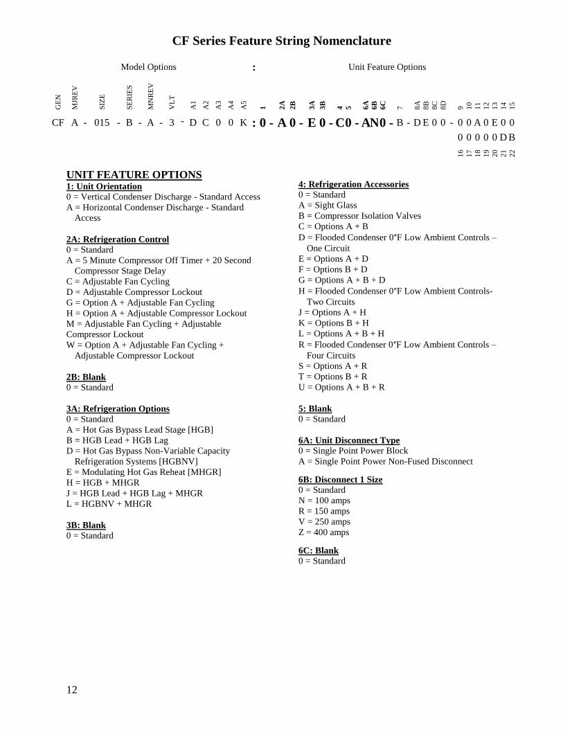
CF Series Feature String Nomenclature
Model Options Unit Feature Options G
EN
MJR
EV
SIZ
E
SE
RIE
S
MN
RE
V
VL
T
A1
A2
A3
A4
A5
1
2A
2B
3A
3B
4
5
6A
6B
6C
7
8A
8B
8C
8D
9
10
11
12
13
14
15
CF A - 015 - B - A - 3 - D C 0 0 K 0 - A 0 - E 0 - C 0 - A N 0 - B - D E 0 0 - 0 0 A 0 E 0 0
0 0 0 0 0 D B
16
17
18
19
20
21
22
12
UNIT FEATURE OPTIONS 1 Unit Orientation
0 = Vertical Condenser Discharge - Standard Access
A = Horizontal Condenser Discharge - Standard
Access
2A Refrigeration Control
0 = Standard
A = 5 Minute Compressor Off Timer + 20 Second
Compressor Stage Delay
C = Adjustable Fan Cycling
D = Adjustable Compressor Lockout
G = Option A + Adjustable Fan Cycling
H = Option A + Adjustable Compressor Lockout
M = Adjustable Fan Cycling + Adjustable
Compressor Lockout
W = Option A + Adjustable Fan Cycling +
Adjustable Compressor Lockout
2B Blank
0 = Standard
3A Refrigeration Options
0 = Standard
A = Hot Gas Bypass Lead Stage [HGB]
B = HGB Lead + HGB Lag
D = Hot Gas Bypass Non-Variable Capacity
Refrigeration Systems [HGBNV]
E = Modulating Hot Gas Reheat [MHGR]
H = HGB + MHGR
J = HGB Lead + HGB Lag + MHGR
L = HGBNV + MHGR
3B Blank
0 = Standard
4 Refrigeration Accessories
0 = Standard
A = Sight Glass
B = Compressor Isolation Valves
C = Options A + B
D = Flooded Condenser 0degF Low Ambient Controls ndash
One Circuit
E = Options A + D
F = Options B + D
G = Options A + B + D
H = Flooded Condenser 0degF Low Ambient Controls-
Two Circuits
J = Options A + H
K = Options B + H
L = Options A + B + H
R = Flooded Condenser 0degF Low Ambient Controls ndash
Four Circuits
S = Options A + R
T = Options B + R
U = Options A + B + R
5 Blank
0 = Standard
6A Unit Disconnect Type
0 = Single Point Power Block
A = Single Point Power Non-Fused Disconnect
6B Disconnect 1 Size
0 = Standard
N = 100 amps
R = 150 amps
V = 250 amps
Z = 400 amps
6C Blank
0 = Standard
CF Series Feature String Nomenclature
Model Options Unit Feature Options
GE
N
MJR
EV
SIZ
E
SE
RIE
S
MN
RE
V
VL
T
A1
A2
A3
A4
A5
1
2A
2B
3A
3B
4
5
6A
6B
6C
7
8A
8B
8
C
8D
9
10
11
12
13
14
15
CF A - 015 - B - 0 - 3 - D C 0 0 K 0 - A 0 - E 0 - C 0 - A N 0 - B - D C 0 0 - 0 0 A 0 E 0 0 0 0 0 0 0 D B
16
17
18
19
20
21
22
13
7 Accessories
0 = Standard
B = Phase amp Brown Out Protection
D = Suction Pressure Transducer on Each
Refrigeration Circuit
E = Compressor Sound Blanket
L = Options B + D
M = Options B + E
Q = Options D + E
1 = Options B + D + E
8A Control Sequence
A = Terminal Block for Thermostat w Isolation
Relays
D = VAV Unit Controller - VAV Cool + CAV Heat
E = CAV Unit Controller
F = Makeup Air Unit Controller - CAV Cool + CAV
Heat
H = Constant Volume HP Unit Controller - CAV
Cool + CAV Heat
J = Makeup Air HP Unit Controller - CAV Cool +
CAV Heat
N = Field Installed DDC Controls by Others with
Isolation Relays
8B Control Suppliers
0 = Standard
E = Orion VCC-X (Main Controller in Air Handling
Unit)
H = AAON Touchscreen Controller (Main Controller
in Air Handling Unit)
8C Control Supplier Options
0 = Standard
8D BMS Connection amp Diagnostics
0 = Standard
9 Blank
0 = Standard
10 Blank
0 = Standard
11 Maintenance Accessories
0 = Standard
A = Factory Wired 115VAC Convenience Outlet
B = Field Wired 115VAC Convenience Outlet
C = Service Lights
E = Remote Unit StartStop Terminals
F = Options A + C
H = Options A + E
J = Options B + C
L = Options B + E
N = Options C + E
R = Options A + C + E
U = Options B + C + E
12 Code Options
0 = Standard ETL USA Listing
B = ETL USA + Canada Listing
13 Air-Cooled Condenser Accessories
0 = Standard
A = Condenser Coil Guard
C = ECM Condenser Fan Head Pressure Control
E = VFD Condenser Fan Head Pressure Control
G = Options A + C
J = Options A + E
N = ECM Condenser Fan Head Pressure Control +
Low Sound Condenser Fan
S = Options A + N
14 Blank
0 = Standard
15 Blank
0 = Standard
16 Electrical Options
0 = Standard
17 Shipping Options
0 = Standard
A = Crating
B = Export Crating
CF Series Feature String Nomenclature
Model Options Unit Feature Options G
EN
MJR
EV
SIZ
E
SE
RIE
S
MN
RE
V
VL
T
A1
A2
A3
A4
A5
1
2A
2B
3A
3B
4
5
6A
6B
6C
7
8A
8B
8C
8D
9
10
11
12
13
14
15
CF A - 015 - B - A - 3 - D C 0 0 K 0 - A 0 - E 0 - C 0 - A N 0 - B - D E 0 0 - 0 0 A 0 E 0 0
0 0 0 0 0 D B 1
6
17
18
19
20
21
22
14
18 Blank
0 = Standard
19 Blank
0 = Standard
20 Cabinet Material
0 = Galvanized Steel Cabinet
21 Warranty
0 = Standard
D = Compressor Warranty - Years 2-5
22 Type
B = Premium AAON Gray Paint Exterior
E = Premium AAON Gray Paint Ext + Shrink Wrap
X = SPA + Premium AAON Gray Paint Exterior
1 = SPA + Premium AAON Gray Paint Exterior +
Shrink Wrap
15
General Information
AAON CF Series air-cooled condensers and
condensing units have been designed for
outdoor use only They are factory
assembled wired charged and run-tested
Codes and Ordinances
CF Series units have been tested and
certified by ETL in accordance with UL
Safety Standard 1995CSA C222 No 236
System should be sized in accordance with
the American Society of Heating
Refrigeration and Air Conditioning
Engineers Handbook
Installation of CF Series units must conform
to the ICC standards of the International
Mechanical Code the International Building
Code and local building plumbing and
electrical codes All appliances must be
electrically grounded in accordance with
local codes or in the absence of local codes
the current National Electric Code
ANSINFPA 70 or the current Canadian
Electrical Code CSA C221
Receiving Unit
When received the unit should be checked
for damage that might have occurred in
transit If damage is found it should be noted
on the carrierrsquos freight bill A request for
inspection by carrierrsquos agent should be made
in writing at once Nameplate should be
checked to ensure the correct model sizes and
voltages have been received to match the job
requirements
If repairs must be made to damaged goods
then the factory should be notified before any
repair action is taken in order to protect the
warranty Certain equipment alteration
repair and manipulation of equipment
without the manufacturerrsquos consent may void
the product warranty Contact AAON
Technical Support for assistance with
handling damaged goods repairs and freight
claims (918) 382-6450
SHARP EDGES
Coils and sheet metal surfaces present sharp edges and care must be taken when working with equipment
WARNING
QUALIFIED INSTALLER
Improper installation adjustment alteration service or maintenance can cause property damage personal injury or loss of life Installation and service must be performed by a Factory Trained Service Technician
WARNING
Failure to observe the following instructions will result in premature failure of your system and possible voiding of the warranty
WARNING
16
Storage
If installation will not occur immediately
following delivery store equipment in a dry
protected area away from construction traffic
and in the proper orientation as marked on the
packaging with all internal packaging in
place Secure all loose-shipped items
Failure to observe the following instructions
will result in premature failure of your
system and possible voiding of the warranty
Never turn off the main power supply to the
unit except for complete shutdown When
power is cut off from the unit any
compressors using crankcase heaters cannot
prevent refrigerant migration This means the
compressor will cool down and liquid
refrigerant may accumulate in the
compressor The compressor is designed to
pump refrigerant gas and damage may occur
if liquid enters the compressor when power is
restored
Before unit operation the main power switch
must be turned on for at least twenty-four
hours for units with compressor crankcase
heaters This will give the crankcase heater
time to clear any liquid accumulation out of
the compressor before it is required to run
Always control the system from the control
panel never at the main power supply (except
for emergency or for complete shutdown of
the system)
CLEAN AIR ACT
The Clean Air Act of 1990 bans the intentional venting of refrigerant as of July 1 1992 Approved methods of recovery recycling or reclaiming must be followed
CAUTION
CRANKCASE HEATER OPERATION
Units are equipped with compressor crankcase heaters which should be energized at least 24 hours prior to cooling operation to clear any liquid refrigerant from the compressors
CAUTION
3-PHASE ROTATION
Rotation must be checked on all MOTORS AND COMPRESSORS of three phase units All motors to include and not be limited to pump motors and condenser fan motors should all be checked by a qualified service technician at startup and any wiring alteration should only be made at the unit power connection
CAUTION
17
The standard compressors must be on a
minimum of 5 minutes and off for a minimum
of 5 minutes The cycle rate must be no more
than 6 starts per hour
The variable capacity compressors must be
on a minimum of 3 minutes and off for a
minimum of 3 minutes The cycle rate must
be no more than 6 starts per hour
The compressor life will be seriously
shortened by reduced lubrication and the
pumping of excessive amounts of liquid oil
and liquid refrigerant
Wiring Diagrams
A complete set of unit specific wiring
diagram in point-to-point form is laminated
in plastic and located inside the control
compartment door
General Maintenance
When the initial startup is made and on a
periodic schedule during operation it is
necessary to perform routine service checks
on the performance of the condensing unit
This includes reading and recording suction
pressures and checking for normal sub-
cooling and superheat
COMPRESSOR ROTATION
Scroll compressors are directional and will be damaged by operation in the wrong direction Low pressure switches on compressors have been disconnected after factory testing Rotation should be checked by a qualified service technician at startup using suction and discharge pressure gauges and any wiring alteration should only be made at the unit power connection
COMPRESSOR CYCLING
5 MINUTE MINIMUM OFF TIME To prevent motor overheating compressors must cycle off for a minimum of 5 minutes
5 MINUTE MINIMUM ON TIME To maintain the proper oil level compressors must cycle on for a minimum of 5 minutes The cycle rate must not exceed 6 starts per hour
WARNING
CAUTION
18
Installation
Forklifting the Unit
CF Series condensing unit sizes 2-25 amp 30
tons can be lifted using a forklift 2-7 ton
units must have forks at least 48rdquo in length
9-25 amp 30 ton units must have forks 72rdquo in
length or the forks must have 72rdquo fork
extensions Standard units can be lifted from
all sides except the condenser coil side CF
Series condensing unit sizes 26 amp 31-70 tons
cannot be lifted using a forklift They can be
lifted as shown in Figure 3
Forks must be perpendicular to the unit and
they must be in far enough that the back of
the forks are no more than 6rdquo away from the
edge of the unit
Figure 1 - Forklifting a CF Series A Cabinet
Figure 2 - Forklifting a CF Series B and C
Cabinet
FORKLIFTING 2-7 TON UNITS
Forks or Fork Extensions must be at least 48rdquo in length
CAUTION
FORKLIFTING 9-25 amp 30 TON UNITS
Forks or Fork Extensions must be at least 72rdquo in length
CAUTION
19
Lifting the Unit
If cables or chains are used to hoist the unit
they must be the same length Minimum
cable length is 99rdquo for CF Series 9-70 ton
units CF Series 2-7 ton units do not include
factory installed lifting lugs and should be
lifted by forklift only Care should be taken
to prevent damage to the cabinet coils and
condenser fans
Before lifting unit be sure that all shipping
material has been removed from unit Secure
hooks and cables at all lifting points lugs
provided on the unit
Figure 3 ndash Lifting Details and Orientation of
a CF Series 9-70 ton Condensing Unit
Locating the Unit
The CF Series condenser and condensing unit
is designed for outdoor applications and
mounting at ground level or on a rooftop It
must be placed on a level and solid
foundation that has been prepared to support
its weight When installed at ground level a
one-piece concrete slab should be used with
footings that extend below the frost line Also
with ground level installation care must be
taken to protect the coil fins from damage due
to vandalism or other causes
The first clearance table below gives the
clearance values for proper unit operation
The second clearance table gives the
clearance necessary for removing the coil
without disassembling a large part of the
condensing unit For ease of removing the
condenser coil use the second table
clearances for the right hand side of the unit
Table 1 ndashClearances for Proper Operation
Location Unit Size
2-7 tons 9-70 tons
Front -
(Controls
Side)
Unobstructed 36rdquo
Left Side 6rdquo 30rdquo
Right Side 6rdquo 36rdquo
Top 3rdquo Unobstructed
Back 18rdquo 6rdquo
Table 2 ndash Clearances for Coil Pull
Unit Size Right Hand Side
2-7 tons 42rdquo
9-15 tons 42rdquo
16-25 amp 30 tons 54rdquo
26 amp 31-70 tons 66rdquo
Figure 4 - Orientation of Series 2-7 ton
Condensing Unit
20
The placement relative to the building air
intakes and other structures must be carefully
selected Airflow to and from the condenser
or condensing unit must not be restricted to
prevent a decrease in performance and
efficiency
The installation position for 9-70 ton units
must provide at least 30rdquo of left and right side
clearance for proper airflow to the condenser
coils When units are mounted adjacent to
each other the minimum right and left side
clearance required between the units is 60rdquo or
5 feet Similarly when 2-7 ton units are
mounted adjacent to each other the minimum
clearance required between the back side of
the units is 36rdquo or 3 feet
Units should not be installed in an enclosure
or pit that is deeper than the height of the unit
When recessed installation is necessary the
clearance to maintain proper airflow is at
least 5 feet (3 feet for 2-7tons)
CF Series condensers and condensing units
that have a vertical air discharge must have
no obstruction above the equipment Do not
place the unit under an overhang CF Series
condensers and condensing units that have a
horizontal discharge must have no
obstruction in front of the unit
For proper unit operation the immediate area
around condenser must remain free of debris
that may be drawn in and obstruct airflow in
the condensing section
Consideration must be given to obstruction
caused by snow accumulation when placing
the unit
Mounting Isolation
For roof mounted applications or anytime
vibration transmission is a factor vibration
isolators may be used
Access Doors
Access doors are provided to the compressor
and electrical compartment
Standard Evacuation Instructions
Proper system evacuation is critical to
remove moisture and non-condensables from
the system before charging the system with
refrigerant A newly installed AAON
condensing unit has already been evacuated
and charged with some refrigerant at the
factory When evacuating a new system
keep the condensing unit service valves
closed and evacuate the suction and liquid
lines and the air handling unit If the entire
system must be evacuated use the following
procedure to ensure the entire system is
pulled into a good vacuum
1 System evacuation should be
performed anytime a system is open to
atmospheric pressure The POE oils
used with R-410A are extremely
hydroscopic in nature and immediately
begin pulling in moisture once the
system is opened to the atmosphere
2 Before starting to evacuate the
system you MUST ensure that there are
no leaks by pressurizing the system with
PVC PIPING
PVC (Polyvinyl Chloride) and CPVC (Chlorinated Polyvinyl Chloride) are vulnerable to attack by certain chemicals Polyolester (POE) oils used with R-410A and other refrigerants even in trace amounts in a PVC or CPVC piping system will result in stress cracking of the piping and fittings and complete piping system failure
CAUTION
21
400 psig of dry nitrogen and verifying no
pressure loss after one hour
3 Four valve manifold gauge sets are
more effective than standard manifold
gauge sets due to the extra hose port in
combination with a 38rsquorsquo evacuation
port The larger diameter evacuation port
will expedite system evacuation
4 The manifold set should be connected
to the condensing unit with one hose on
the suction line service valve one hose
on the liquid line service valve and if an
extra Schrader valve is field installed on
the suction line connect a third hose (not
shown) The vacuum pump should be
connected to the manifold set using a
38rdquo vacuum rated hose Figure 5 shows
two circuits Both circuits must be
evacuated separately
Figure 5 ndash CU evacuation connections
5 An accurate micron gauge must be
used and checked by pulling a vacuum
on the gauge by itself and verify a rapid
drop to less than 100 microns within a
few minutes
6 The micron gauge should not be
attached to the system until the gauge
manifold is reading 28rsquorsquo of vacuum to
ensure the micron gauge does not see
pressure and is thus damaged MICRON
GAUGES WILL BE DAMAGED BY
PRESSURE
7 It is a good practice to replace the
vacuum pump oil after one hour of the
evacuation process The oil can be
broken down in the pump in the initial
first hour causing system evacuation to
take longer than it should
8 The minimum micron level required
by AAON is 350 microns for systems
using POE oils
9 The system should then be isolated
and the pump turned off to check for
vacuum rise due to leaks or moisture in
the system The micron gauge should
not rise above 500 microns after 30
minutes of wait time
Low Ambient amp Modulating Reheat
System Evacuation Instructions
Proper system evacuation is critical to
remove moisture and non-condensables from
the system before charging the system with
refrigerant Systems with low ambient
flooded condenser option require the
following procedure to ensure the entire
system is pulled into a good vacuum
1 System evacuation should be
performed anytime a system is open to
atmospheric pressure The POE oils
used with R-410A are extremely
hydroscopic in nature and immediately
begin pulling in moisture once the
system is opened to the atmosphere
2 Open the reheat valve to 50 when
evacuating
3 Before starting to evacuate the
system you MUST ensure that there are
no leaks by pressurizing the system with
22
400 psig of dry nitrogen and verifying no
pressure loss after one hour
4 Four valve manifold gauge sets are
more effective than standard manifold
gauge sets due to the extra hose port in
combination with a 38rsquorsquo evacuation
port The larger diameter evacuation port
will expedite system evacuation
5 The manifold set should be connected
to the condensing unit with one hose on
the suction line service valve one hose
on the liquid line service valve and a
third hose on the reheat line service
valve The vacuum pump should be
connected to the manifold set using a
38rdquo vacuum rated hose Figure 6 shows
two circuits The first circuit has a
reheat line the second circuit is just the
suction and liquid line Both circuits
must be evacuated separately
Figure 6 ndash CU evacuation connections
6 FAILURE to connect to the liquid
line service valve will result in the
receiver tank not being fully evacuated
and most likely lead to non-
condensables in the system
7 An accurate micron gauge must be
used and checked by pulling a vacuum
on the gauge by itself and verify a rapid
drop to less than 100 microns within a
few minutes
8 The micron gauge should not be
attached to the system until the gauge
manifold is reading 28rsquorsquo of vacuum to
ensure the micron gauge does not see
pressure and is thus damaged MICRON
GAUGES WILL BE DAMAGED BY
PRESSURE
9 It is a good practice to replace the
vacuum pump oil after one hour of the
evacuation process The oil can be
broken down in the pump in the initial
first hour causing system evacuation to
take longer than it should
10 The minimum micron level required
by AAON is 350 microns for systems
using POE oils
11 The system should then be isolated
and the pump turned off to check for
vacuum rise due to leaks or moisture in
the system The micron gauge should
not rise above 500 microns after 30
minutes of wait time
Adjusting Refrigerant Charge
All AAON CF Series condensers and
condensing units are shipped with a factory
holding charge The factory charge is
different depending on the unit size and
system (heat pump modulating hot gas
reheat LAC) The factory charge per circuit
is shown on the unit nameplate Adjusting the
charge of the system will be required during
installation
23
Adjusting the charge of a system in the field
must be based on determination of liquid sub-
cooling and evaporator superheat On a
system with a thermostatic expansion valve
liquid sub-cooling is more representative of
the charge than evaporator superheat but both
measurements must be taken
Before Charging
Refer to the Unit Nameplate to determine
which refrigerant must be used to charge the
system
Unit being charged must be at or near full
load conditions before adjusting the charge
Units equipped with hot gas bypass must
have the hot gas bypass valve closed to get
the proper charge
Units equipped with hot gas reheat must be
charged with the hot gas valve closed while
the unit is in cooling mode After charging
unit should be operated in reheat
(dehumidification) mode to check for correct
operation
Units equipped with heat pump options
should be charged in cooling mode to get the
proper charge After charging unit should be
operated in heating mode to check for correct
charge Charge may need to be adjusted for
heating mode If adjustments are made in the
heating mode cooling mode must be rerun to
verify proper operation
After adding or removing charge the system
must be allowed to stabilize typically 10-15
minutes before making any other
adjustments
The type of unit and options determine the
ranges for liquid sub-cooling and evaporator
superheat Refer to Table 3 when determining
the proper sub-cooling
For units equipped with low ambient (0degF)
option see the special charging instructions at
the end of this section
Checking Liquid Sub-cooling
Measure the temperature of the liquid line as
it leaves the condenser coil
Read the gauge pressure at the liquid line
close to the point where the temperature was
taken You must use liquid line pressure as it
will vary from discharge pressure due to
condenser coil pressure drop
Convert the pressure obtained to a saturated
temperature using the appropriate refrigerant
temperature-pressure chart
COMPRESSOR LUBRICANT
Polyolester (POE) and Polyvinylether (PVE) oils are two types of lubricants used in hydrofluorocarbon (HFC) refrigeration systems Refer to the compressor label for the proper compressor lubricant type
CAUTION
CLEAN AIR ACT
The Clean Air Act of 1990 bans the intentional venting of refrigerant (CFCrsquos and HCFCrsquos) as of July 1 1992 Approved methods of recovery recycling or reclaiming must be followed Fines andor incarceration may be levied for non-compliance
CAUTION
24
Subtract the measured liquid line temperature
from the saturated temperature to determine
the liquid sub-cooling
Compare calculated sub-cooling to Table 3
for the appropriate unit type and options
Table 3 - Acceptable Refrigeration Circuit
Values
Cooling
Mode
Liquid Sub-
Cooling
Values
Cooling Only Unit4 8-15degF
Cooling Only Unit with Hot
Gas Reheat14 5-15degF
Heat PumpUnit24 2-4degF
Heat Pump Unit with Hot
Gas Reheat34 2-6degF
Cooling Only Unit with
LAC4 8-15degF
Cooling Only Unit with Hot
Gas Reheat amp LAC4 8-15degF
Notes 1 Must be charged with the hot gas valve
closed After charging unit should be
operated in reheat (dehumidification) mode
to check for correct operation
2 The sub-cooling value in this table is for the
unit running in cooling mode of operation
After charging unit should be operated in
heating mode to check for correct operation
3 The sub-cooling value in this table is for the
unit running in cooling mode of operation
and the hot gas valve closed After charging
unit should be operated in reheat
(dehumidification) mode to check for correct
operation and then in heating mode to check
for correct operation
4 Sub-cooling must be increased by 1degF per 10
feet of vertical liquid line rise for R-410A
(AHU above CU) For example a cooling
only unit with hot gas reheat and a vertical
liquid drop can charge to a sub-cooling value
of 5-15degF but a cooling only unit with hot
gas reheat and a vertical liquid rise of 30 ft
must charge to a sub-cooling value of at least
8-15degF DO NOT OVERCHARGE
Refrigerant overcharging leads to excess
refrigerant in the condenser coils resulting in
elevated compressor discharge pressure
Checking Evaporator Superheat
Measure the temperature of the suction line
close to the compressor
Read gauge pressure at the suction line close
to the compressor
Convert the pressure obtained to a saturated
temperature using the appropriate refrigerant
temperature-pressure chart
Subtract the saturated temperature from the
measured suction line temperature to
determine the evaporator superheat
For refrigeration systems with tandem
compressors it is critical that the suction
superheat setpoint on the TXV is set with one
compressor running The suction superheat
should be 10-13degF with one compressor
running The suction superheat will increase
with both compressors in a tandem running
Inadequate suction superheat can allow liquid
refrigerant to return to the compressors which
will wash the oil out of the compressor Lack
of oil lubrication will destroy a compressor
Liquid sub-cooling should be measured with
both compressors in a refrigeration system
running
Compare calculated superheat to the
acceptable cooling mode superheat values of
8-15degF for all system types Superheat will
increase with long suction line runs
25
Adjusting Sub-cooling and Superheat
Temperatures
The system is overcharged if the sub-cooling
temperature is too high compared to Table 3
and the evaporator is fully loaded (low loads
on the evaporator result in increased sub-
cooling) and the evaporator superheat is
within the temperature range of 8-15degF (high
superheat results in increased sub-cooling)
Correct an overcharged system by reducing
the amount of refrigerant in the system to
lower the sub-cooling
The system is undercharged if the superheat
is too high and the sub-cooling is too low
Correct an undercharged system by adding
refrigerant to the system to reduce superheat
and raise sub-cooling
If the sub-cooling is correct and the superheat
is too high the TXV may need adjustment to
correct the superheat
DO NOT OVERCHARGE Refrigerant overcharging leads to excess refrigerant in the condenser coils resulting in elevated compressor discharge pressure
CAUTION
EXPANSION VALVE ADJUSTMENT
Thermal expansion valves must be adjusted to approximately 8-15degF of suction superheat Failure to have sufficient superheat will damage the compressor and void the warranty
CAUTION
26
Special Low Ambient Option Charging
Instructions
For units equipped with low ambient
refrigerant flood back option being charged
in the summer when the ambient
temperature is warm
If the ambient is above 70degF charge to
approximately 1-2degF of sub-cooling
measured at the inlet to the expansion valve
Once enough charge has been added to get
the evaporator superheat and sub-cooling
values to the correct setting more charge
must be added Use Table 4 to find the
additional charge amount required for the
system when running in cold ambient
conditions
Table 4 ndash Charge to Flood Condenser Coil
for Ambient Above 70degF
CF Size of
circuits
Per Circuit
Charge (lbs)
CF 2 3 1 49
CF 4 5 6 7 1 92
CF 9 11 2 91
CF 13 15 2 121
CF 16 18 2 131
CF 20 25 30 2 175
CF 26 31 40 2 180
4 91
CF 50 60 70 2 438
4 221
For units equipped with low ambient
refrigerant flood back option being charged
in the winter when the ambient
temperature is cold
1 If the ambient is below 70degF charge
to approximately 1-2degF of sub-cooling
measured at the inlet to the expansion
valve Once enough charge has been
added to get the evaporator superheat
and sub-cooling values to the correct
setting more charge may need to be
added If the ambient temperature is 0degF
no more charge is required Ambient
temperatures above 0degF will require a
percentage of the per circuit charge
values from Table 4 Using your
ambient temperature find the
percentage value from Table 5 and
multiply the Per Circuit Charge value
from Table 4 and the value to
determine the additional charge amount
Table 5 ndash Charge to Flood Condenser
Coil for Ambient Below 70degF
Condenser
Ambient
Temperature ˚F
Percentage
Per Circuit
Charge from
Table 4
60 60
50 37
40 24
30 15
20 8
0 0
2 The unit should be checked for proper
operation once the ambient temperature
is above 80degF
Example A CF size 31 with tandem
compressors where the ambient
temperature is 40degF
From Table 4 ndash 18 lbs refrigerant charge
per circuit (tandem compressors would
have 2 circuits in this size of CF)
From Table 5 ndash 24 of Table 4 charge
Additional charge needed for a unit with
low ambient flooded condenser controls
= 18 lbs 024 = 432 lbs additional
refrigerant charge per circuit
27
Low Ambient Operation
During low ambient temperatures the vapor
refrigerant will migrate to the cold part of the
system and condense into liquid All CF
Series compressors are provided with factory
installed crankcase heaters to help prevent
liquid refrigerant from slugging the
compressors during startup in low ambient
conditions The condenser or condensing unit
must have continuous power 24 hours prior
to startup This ensures the compressor will
receive sufficient refrigerant vapor at startup
Standard units can operate down to 55degF
ambient temperature
AAON condenser fan head pressure control
units can operate down to 35degF ambient
temperature Three different condenser fan
head pressure control options available are
adjustable fan cycling ECM condenser fan
or VFD controlled condenser fans See
detailed information following
The AAON low ambient (condenser flood-
back) system is used to operate a refrigerant
system down to 0degF outside air temperature
See detailed information following
Fan Cycling Low Ambient
Adjustable fan cycling is a low ambient head
pressure control option that cycles the
condenser fans to maintain refrigerant circuit
head pressures at acceptable levels during
cooling operation The head pressure set
point (100-470 psi) and pressure differential
(35-200 psi) can be field adjusted using a
flathead screwdriver For example if the
head pressure is set to 300psi and the
differential is set to 100psi then fans will cut
in at 300psi and cut out at 200psi Fan
cycling and variable speed condenser fan
head pressure control options allow
mechanical cooling with ambient
temperatures down to 35degF
Figure 7 - Adjustable Fan Cycling Switch
Variable Speed Low Ambient
Variable speed condenser fan head pressure
control is a low ambient head pressure
control option that sends a variable signal in
relation to the refrigerant circuit head
pressure of the system to an electronically
commutated motor (ECM) or VFD The
motor either speeds up or slows down air
flow accordingly in order to maintain
constant head pressure Fan cycling and
variable speed condenser fan head pressure
control options allow mechanical cooling
with ambient temperatures down to 35degF
Flooded Condenser Low Ambient
Flooded condenser low ambient control
maintains normal head pressure during
periods of low ambient When the ambient
temperature drops the condensing
temperature and therefore pressure drops
Without ambient control the system would
shut down on low discharge pressure The
flooded condenser method of low ambient
control fills the condenser coil with liquid
refrigerant decreasing the heat transfer
capacity of the coil which allows the coil to
operate at an acceptable discharge pressure
28
The condenser coil will not be flooded during
summer ambient temperatures so a receiver
is included to store the additional liquid
refrigerant required to flood the condenser
coil in low ambient The receiver is factory-
sized to contain all of the flooded volume
Without a receiver there would be high head
pressures during higher ambient conditions
The low ambient system maintains normal
head pressure during periods of low ambient
by restricting liquid flow from the condenser
to the receiver and at the same time
bypassing hot gas around the condenser to the
inlet of the receiver This reduces liquid
refrigerant flow from the condenser reducing
its effective surface area which in turn
increases the condensing pressure At the
same time the bypassed hot gas raises liquid
pressure in the receiver allowing the system
to operate properly CF Series condensers
and condensing units use an LAC valve for
low ambient operation
LAC Valve
The Low Ambient Control (LAC) valve is a
non-adjustable three way valve that
modulates to maintain receiver pressure As
the receiver pressure drops below the valve
setting (295 psig for R-410A) the valve
modulates to bypass discharge gas around the
condenser The discharge gas warms the
liquid in the receiver and raises the pressure
to the valve setting The following schematic
shows an example system using the LAC
valve
Figure 8 ndash LAC Piping Example
29
Refrigerant Piping
(See back of the manual for refrigerant piping
diagrams)
General
Piping from the condensing unit to the air
handler is the responsibility of the installing
contractor
Use only clean type ldquoACRrdquo copper tubing
that has been joined with high temperature
brazing alloy
The pipe or line sizes must be selected to
meet the actual installation conditions and
NOT simply based on the connection sizes at
the condensing unit or air handler
All CF Series condensing units are provided
with in-line shutoff valves on both the liquid
and suction lines These should remain closed
until the system is ready for start-up after
installation
Piping should conform to generally accepted
practices and codes
Care must be taken not to cross the circuits
on multiple circuit systems
Upon completion of piping connection the
interconnecting piping and air handler MUST
BE evacuated to 500 microns or less leak
checked and charged with refrigerant
Determining Refrigerant Line Size
The piping between the condenser and low
side must ensure
1 Minimum pressure drop and
2 Continuous oil return and
3 Prevention of liquid refrigerant slugging
or carryover
Minimizing the refrigerant line size is
favorable from an economic perspective
reducing installation costs and reducing the
potential for leakage However as pipe
diameters decrease pressure drop increases
Excessive suction line pressure drop causes
loss of compressor capacity and increased
power usage resulting in reduced system
efficiency Excessive pressure drops in the
liquid line can cause the liquid refrigerant to
flash resulting in faulty TXV operation and
improper system performance In order to
operate efficiently and cost effectively while
avoiding malfunction refrigeration systems
must be designed to minimize both cost and
pressure loss
REFRIGERANT PIPING
Line sizes must be selected to meet actual installation conditions not simply based on the connection sizes at the condensing unit or air handling unit
CAUTION
REFRIGERANT PIPING
This section is for information only and is not intended to provide all details required by the designer or installer of the refrigerant piping between the condenser or condensing unit and the air handling unit AAON Inc is not responsible for interconnecting refrigerant piping Consult ASHRAE Handbook ndash Refrigeration and ASME Standards
CAUTION
30
Equivalent Line Length
All line lengths discussed in this manual
unless specifically stated otherwise are
Equivalent Line Lengths The frictional
pressure drop through valves fittings and
accessories is determined by establishing the
equivalent length of straight pipe of the same
diameter Always use equivalent line
lengths when calculating pressure drop
Special piping provisions must be taken
when lines are up vertical risers or in
excessively long line runs AAON does not
recommend running underground
refrigerant lines
Liquid Line
When sizing the liquid line it is important to
minimize the refrigerant charge to reduce
installation costs and improve system
reliability This can be achieved by
minimizing the liquid line diameter
However reducing the pipe diameter will
increase the velocity of the liquid refrigerant
which increases the frictional pressure drop
in the liquid line and causes other
undesirable effects such as noise
Maintaining the pressure in the liquid line is
critical to ensuring sufficient saturation
temperature avoiding flashing upstream of
the TXV and maintaining system efficiency
Pressure losses through the liquid line due to
frictional contact installed accessories and
vertical risers are inevitable Maintaining
adequate sub-cooling at the condenser to
overcome these losses is the only method to
ensure that liquid refrigerant reaches the
TXV
Liquid refrigerant traveling upwards in a riser
loses head pressure If the evaporator is
below the condenser with the liquid line
flowing down the gravitational force will
increase the pressure of the liquid refrigerant
This will allow the refrigerant to withstand
greater frictional losses without the
occurrence of flashing prior to the TXV
A moisture-indicating sight glass may be
field installed in the liquid line to indicate the
occurrence of premature flashing or moisture
in the line The sight glass should not be used
to determine if the system is properly
charged Use temperature and pressure
measurements to determine liquid sub-
cooling not the sight glass
Liquid Line Routing
Care should be taken with vertical risers
When the system is shut down gravity will
pull liquid down the vertical column and
back to the condenser when it is below the
evaporator This could potentially result in
compressor flooding A check valve can be
installed in the liquid line where the liquid
column rises above the condenser to prevent
this The liquid line is typically pitched along
with the suction line or hot gas line to
minimize the complexity of the
configuration
Liquid Line Insulation
In cooling only systems when the liquid line
is routed through regions where temperature
losses are expected no insulation is required
as this may provide additional sub-cooling to
the refrigerant When routing the liquid line
through high temperature areas insulation of
the line is appropriate to avoid loss of sub-
cooling through heat gain
In heat pump systems when the liquid line is
routed through regions where temperature
losses are expected (all lines exposed to
outside air conditions) insulate with a
minimum 1 inch thick Armaflex insulation
as this will prevent capacity loss during
heating mode of operation
31
Liquid Line Guidelines
In order to ensure liquid at the TXV the sum
of frictional losses and pressure loss due to
vertical rise must not exceed available sub-
cooling A commonly used guideline to
consider is a system design with pressure
losses due to friction through the line not to
exceed a corresponding 1-2degF change in
saturation temperature An additional
recommendation is that the sum of frictional
losses (including valve losses filter drier
losses other accessories and line losses) and
pressure loss due to vertical rise should not
exceed 8degF if the available sub-cooling is
10degF
If the velocity of refrigerant in the liquid line
is too great it could cause excessive noise or
piping erosion The recommended maximum
velocities for liquid lines are 100 fpm from
the condenser to a receiver to discourage
fluid backup and 500 fpm from receiver tank
to the evaporator (300 fpm if the line includes
an electric valve to minimize valve induced
liquid hammer)
Liquid Line Accessories
Liquid line shut off valves and filter driers are
factory provided The total length equivalent
of pressure losses through valves elbows and
fittings must be considered when adding
additional components in the field It is a
good practice to utilize the fewest elbows that
will allow the mating units to be successfully
joined
A liquid line receiver is factory installed on
units with modulating hot gas reheat units
with low ambient control flooded condenser
and units with heat pump
Suction Line
The suction line is more critical than the
liquid line from a design and construction
standpoint More care must be taken to
ensure that adequate velocity is achieved to
return oil to the compressor at minimum
loading conditions However reducing the
piping diameter to increase the velocity at
minimal load can result in excessive pressure
losses capacity reduction and noise at full
load
Suction Line Routing
For cooling only systems pitch the suction
line in the direction of flow (about 1 inch per
20 feet of length) to maintain oil flow
towards the compressor and keep it from
flooding back into the evaporator
For heat pump systems do not pitch lines
since they will be flowing in one direction in
cooling mode and the opposite direction in
heating mode
Crankcase heaters are provided to keep any
condensed refrigerant that collects in the
compressor from causing damage or wear
Make sure to provide support to maintain
suction line positioning and insulate
completely between the evaporator and
condensing unit
It is important to consider part load operation
when sizing suction lines At minimum
capacity refrigerant velocity may not be
adequate to return oil up the vertical riser
Decreasing the diameter of the vertical riser
will increase the velocity but also the
frictional loss
For difficult line routing applications a
double suction riser can be applied to the
situation of part load operation with a suction
riser A double suction riser is designed to
return oil at minimum load while not
incurring excessive frictional losses at full
load A double suction riser consists of a
small diameter riser in parallel with a larger
diameter riser and a trap at the base of the
large riser At minimum capacity refrigerant
velocity is not sufficient to carry oil up both
32
risers and it collects in the trap effectively
closing off the larger diameter riser and
diverting refrigerant up the small riser where
velocity of the refrigerant is sufficient to
maintain oil flow At full load the mass flow
clears the trap of oil and refrigerant is carried
through both risers The smaller diameter
pipe should be sized to return oil at minimum
load while the larger diameter pipe should be
sized so that flow through both pipes
provides acceptable pressure drop at full
load
Figure 9 - Double Suction Riser
Construction
A double riser can also be used for heat pump
operation The specific volume (ft3lb) of
refrigerant at the discharge temperature and
pressure (heating mode line conditions) is
significantly lower than the specific volume
at the suction temperature and pressure
(cooling mode line conditions) To
compound the issue the capacity in heating
mode is lower than the capacity in cooling
mode The discharge velocity in the riser
during heating mode is much lower than the
suction velocity during cooling mode Often
a double riser is necessary to get acceptable
velocities for the discharge mode and
acceptable velocities for the suction mode In
the example diagrams (See Figure 10 amp
Figure 11) the cooling mode will use both
lines and the heating mode will use only one
Suction Line Traps
Include a trap immediately after the
evaporator coil outlet to protect the TXV bulb
from liquid refrigerant
Include traps every 20 feet in vertical suction
riser sections for cooling only systems and
every 12 feet for heat pump systems
Suction Line Insulation
The entire suction line should be insulated
with a minimum 1 inch thick Armaflex
insulation This prevents condensation from
forming on the line and reduces any potential
loss in capacity associated with heat gain
placing additional load on the system This
line should still be insulated in heat pump
systems even though it acts as both a
discharge and suction line
Suction Line Guidelines
For proper performance suction line
velocities less than a 4000 fpm maximum are
recommended The minimum velocity
required to return oil is dependent on the pipe
diameter however a general guideline of
1000 fpm minimum may be applied
When suction flow is up variable capacity
compressors require a minimum velocity of
1500 fpm at full load
Tandem compressors must be considered for
full load operation (both compressors
operating) and at partial load (only one
compressor operating) When suction flow is
up and the tandem has a variable capacity
compressor the velocity for only one
compressor in operation must be greater than
1500 fpm For onoff compressors the
velocity must be greater than the minimum
velocity required to return oil
Heat pump vapor lines must be checked for
suction flow (cooling mode operation) and
discharge flow (heating mode operation)
33
The same line must be used for both modes
of operation
In a fashion similar to the liquid line a
common guideline to consider is a system
design with pressure losses due to friction
through the line not to exceed a
corresponding 1-2degF change in saturation
temperature
For split system piping with long horizontal
runs and short vertical risers a smaller pipe
size can be used to provide sufficient velocity
to return oil in vertical risers at part loads and
a larger size pipe can be used on the
horizontal runs and vertical drop sections
This helps with oil return yet keeps the
pressure drop to a minimum
Suction Line Accessories
If the job requirements specify suction
accumulators they must be separately
purchased and field installed Heat pump
units will include a factory installed suction
accumulator
Discharge Line
The discharge line is similar to the suction
line from a design and construction
standpoint Care must be taken to ensure that
adequate velocity is achieved to return oil to
the compressor at minimum loading
conditions However reducing the piping
diameter to increase the velocity at minimal
load can result in excessive pressure losses
capacity reduction and noise at full load
Pressure loss in the discharge line has less of
an impact on capacity than pressure loss in
the suction line Pressure loss in the
discharge line causes the compressors to
work harder and thus use more power
Discharge Line Routing
For cooling only remote condenser systems
pitch the discharge line in the direction of
flow (about 1 inch per 20 feet of length) to
maintain oil flow towards the compressor
In a heat pump system the field installed
suction line is also used as a discharge line in
the heating mode of operation so the line
must be sized to meet both the suction line
conditions in cooling mode and the discharge
line conditions in heating mode
Because it is used in both directions for a heat
pump unit the line should be installed level
not pitched to facilitate oil return in both
modes of operation
It is important to consider part load operation
when sizing discharge lines At minimum
capacity refrigerant velocity may not be
adequate to return oil up the vertical riser
Decreasing the diameter of the vertical riser
will increase the velocity but also the
frictional loss
For difficult line routing applications a
double discharge riser can be applied to the
situation of part load operation with a
discharge riser A double discharge riser is
designed to return oil at minimum load while
not incurring excessive frictional losses at
full load A double discharge riser consists of
a small diameter riser in parallel with a larger
diameter riser and a trap at the base of the
large riser At minimum capacity refrigerant
velocity is not sufficient to carry oil up both
risers and it collects in the trap effectively
closing off the larger diameter riser and
diverting refrigerant up the small riser where
SUCTION RISER TRAPS
Circuits require suction riser traps every 20 feet (every 12 feet for heat pumps)
CAUTION
34
velocity of the refrigerant is sufficient to
maintain oil flow At full load the mass flow
clears the trap of oil and refrigerant is carried
through both risers The smaller diameter
pipe should be sized to return oil at minimum
load while the larger diameter pipe should be
sized so that flow through both pipes
provides acceptable pressure drop at full
load (See the Double Suction Riser
Construction Figure 9)
A double riser can also be used for heat pump
operation The specific volume (ft3lb) of
refrigerant at the discharge temperature and
pressure (heating mode line conditions) is
significantly lower than the specific volume
at the suction temperature and pressure
(cooling mode line conditions) To
compound the issue the capacity in heating
mode is lower than the capacity in cooling
mode The discharge velocity in the riser
during heating mode is much lower than the
suction velocity during cooling mode Often
a double riser is necessary to get acceptable
velocities for the discharge mode and
acceptable velocities for the suction mode In
the example diagrams the cooling mode will
use both lines and the heating mode will use
only one See the following schematics that
illustrate how the double discharge riser can
work for heat pump applications
Figure 10 ndash Heat Pump Piping Schematic of
Cooling Mode in Double Riser
Figure 11 ndash Heat Pump Piping Schematic of
Heating Mode in Double Riser
35
Discharge Line Traps
Include traps every 12 feet in vertical
discharge riser sections
Discharge Line Insulation
Although a typical discharge line does not
need to be insulated the suction line does
Since the same line is used for both the line
must be insulated as described in the Suction
Line Insulation section
Discharge Line Guidelines
For proper performance discharge line
velocities less than a 3500 fpm maximum are
recommended The minimum velocity
required to return oil is dependent on the pipe
diameter however a general guideline of
900 fpm minimum may be applied
When discharge flow is up variable capacity
compressors require a minimum velocity of
900 fpm at full load
Tandem compressors must be considered for
full load operation (both compressors
operating) and at partial load (only one
compressor operating) When discharge flow
is up and the tandem has a variable capacity
compressor the velocity for only one
compressor in operation must be greater than
900 fpm For onoff compressors the
velocity must be greater than the minimum
velocity required to return oil
Heat pump vapor lines must be checked for
suction flow (cooling mode operation) and
discharge flow (heating mode operation)
The same line must be used for both modes
of operation
In a fashion similar to the suction line a
common guideline to consider is a system
design with pressure losses due to friction
through the line not to exceed a
corresponding 1-2degF change in saturation
temperature
For split system piping with long horizontal
runs and short vertical risers a smaller pipe
size can be used to provide sufficient velocity
to return oil in vertical risers at part loads and
a larger size pipe can be used on the
horizontal runs and vertical drop sections
This helps with oil return yet keeps the
pressure drop to a minimum
Hot Gas Bypass Line
Hot Gas Bypass is available for use with DX
systems that may experience low suction
pressure during the operating cycle This may
be due to varying load conditions associated
with VAV applications or units supplying a
large percentage of outside air The system is
designed to divert refrigerant from the
compressor discharge to the low pressure
side of the system in order to keep the
evaporator from freezing and to maintain
adequate refrigerant velocity for oil return at
minimum load
Hot discharge gas is redirected to the
evaporator inlet via an auxiliary side
connector (ASC) to false load the evaporator
when reduced suction pressure is sensed
Field piping between the condensing unit
and the evaporator is required
Hot Gas Bypass Piping Considerations
Pitch the hot gas bypass (HGB) line
downward in the direction of refrigerant
flow toward the evaporator
DISCHARGE RISER TRAPS
Circuits require discharge riser traps every 12 feet
CAUTION
36
When installing vertical hot gas bypass lines
an oil drip line must be provided at the lowest
point in the system The oil drip line must be
vertical its diameter should be the same as
the diameter of the riser and it should be
1 foot long Install a sight glass in the oil drip
line for observation Run an oil return line
using 18 inch capillary tube 10 feet in
length from the hot gas bypass line oil drip
line to the suction line Connect the oil return
line below the sight glass and 1 inch above
the bottom of the oil drip line
Figure 12 ndash Oil Return Line
HGB valves are adjustable Factory HGB
valve settings will be sufficient for most
applications but may require slight
adjustments for some applications including
some make up air applications
Insulate the entire length of the HGB line
with a minimum 1 inch thick Armaflex
insulation
Hot Gas Bypass Line Guidelines
Choose a small size line to ensure oil return
and minimize refrigerant charge
Maintain velocities below a maximum of
3500 fpm A general minimum velocity
guideline to use is approximately 2000 fpm
Hot Gas Reheat
The AAON modulating hot gas reheat system
diverts hot discharge gas from the condenser
to the air handling unit through the hot gas
line Field piping between the condensing
unit and the air handler is required
The line delivers the hot discharge gas to the
reheat coil andor the hot gas bypass valve so
it is sized as a discharge line
Discharge lines should be sized to ensure
adequate velocity of refrigerant to ensure oil
return avoid excessive noise associated with
velocities that are too high and to minimize
efficiency losses associated with friction
Pitch the hot gas line in the direction of flow
for oil return
When installing vertical hot gas reheat lines
an oil drip line must be provided at the lowest
point in the system The oil drip line must be
vertical its diameter should be the same as
the diameter of the riser and it should be
1 foot long Run an oil return line using 18
inch capillary tube 10 feet in length from the
hot gas reheat line oil drip line to the suction
line Connect the oil return line below the
sight glass and 1 inch above the bottom of the
oil drip line (See Oil Return Line Figure 12)
Insulate the entire length of the hot gas line
with a minimum 1 inch thick Armaflex
insulation
Hot Gas Reheat Guidelines
Maintain velocities below a maximum of
3500 fpm A general minimum velocity
guideline is 2000 fpm
37
Electrical
The single point electrical power connections
are made in the electrical control compartment
Verify the unit nameplate voltage agrees with
the power supply Connect power and control
field wiring as shown on the unit specific
wiring diagram provided with the unit
Table 6 - Nameplate Voltage Markings
Voltage Feature
Nameplate
Voltage
Marking
MinMax
VAC
1 230V1Φ60Hz 230 197252
2 230V3Φ60Hz 230 197252
3 460V3Φ60Hz 460 456504
4 575V3Φ60Hz 575 570630
8 208V3Φ60Hz 208 197228
9 208V1Φ60Hz 208 197228
NOTE Units are factory wired for 208V
230V 460V or 575V In some units the 208V
and 230V options may also be provided in
single or three phase configurations The
transformer configuration must be checked by
a qualified technician prior to startup
Size supply conductors based on the unit MCA
rating Supply conductors must be rated a
minimum of 167degF (75degC)
Route power and control wiring separately
through the utility entry Do not run power and
signal wires in the same conduit
Protect the branch circuit in accordance with
code requirements The unit must be
electrically grounded in accordance with local
codes or in the absence of local codes the
current National Electric Code ANSINFPA
70 or the current Canadian Electrical Code
CSA C221
Power wiring is to the unit terminal block or
main disconnect All wiring beyond this point
has been done by the manufacturer and cannot
be modified without affecting the units
agencysafety certification
Three phase voltage imbalance will cause
motor overheating and premature failure The
maximum allowable imbalance is 5
Voltage imbalance is defined as 100 times the
maximum deviation from the average voltage
divided by the average voltage
Example
(218V+237V+235V)3 = 230V then
100(230V-218V)230V = 52 which
exceeds the allowable imbalance
Check voltage imbalance at the unit disconnect
switch and at the compressor terminal
Contact your local power company for line
voltage corrections
3-PHASE ROTATION
Rotation must be checked on all MOTORS AND COMPRESSORS of three phase units Condenser fan motors should be checked by a qualified service technician at startup and any wiring alteration should only be made at the unit power connection Variable frequency drives are programmed to automatically rotate the fan in the correct rotation Do not rely on fans with variable frequency drives for compressor rotation
CAUTION
38
NOTE Startup technician must check for
proper motor rotation and check fan motor
amperage listed on the motor nameplate is not
exceeded Motor overload protection may be a
function of the variable frequency drive and
must not be bypassed
Wire control signals to the unitrsquos low voltage
terminal block located in the controls
compartment
If any factory installed wiring must be
replaced use a minimum 221degF (105degC) type
AWM insulated conductors
ELECTRIC SHOCK
Electric shock hazard Before attempting to perform any installation service or maintenance shut off all electrical power to the unit at the disconnect switches Unit may have multiple power supplies Failure to disconnect power could result in dangerous operation serious injury death or property damage
WARNING
SEALING ELECTRICAL ENTRIES
Installing Contractor is responsible for proper sealing of the electrical entries into the unit Failure to seal the entries may result in damage to the unit and property
CAUTION
39
Startup (See back of the manual for startup form)
Before startup of the condenser or condensing
unit make sure that the following items have
been checked
1 Verify that electrical power is available to
the unit
2 Verify that any remote stopstart device
connected to the unit controller is
requesting the unit to start
Cycle through all the compressors to confirm
that all are operating within tolerance
While performing the check use the startup
form to record observations of amps and
refrigerant pressures
When all is running properly place the
controller in the Run mode and observe the
system until it reaches a steady state of
operation
Compressor Operation
The compressors must be off for a minimum of
5 minutes and on for a minimum of 5 minutes
Short cycling of the compressors can cause
undue stress and wear
3-PHASE ROTATION
Rotation must be checked on all MOTORS AND COMPRESSORS of three phase units Condenser fan motors should all be checked by a qualified service technician at startup and any wiring alteration should only be made at the unit power connection Variable frequency drives are programmed to automatically rotate the fan in the correct rotation Do not rely on fans with variable frequency drives for compressor rotation
CAUTION
ELECTRIC SHOCK
Electric shock hazard Shut off all electrical power to the unit to avoid shock hazard or injury from rotating parts
WARNING
QUALIFIED INSTALLER
Improper installation adjustment alteration service or maintenance can cause property damage personal injury or loss of life Startup and service must be performed by a Factory Trained Service Technician
WARNING
Before completing installation a complete operating cycle should be observed to verify that all components are functioning properly
CAUTION
40
Variable Capacity Compressor Controller
Units with variable capacity scroll
compressors may include a variable capacity
compressor controller The following is an
explanation of the terminals and
troubleshooting of the alert flash codes on the
controller For more information on the
compressor controller see Emerson Climate
Bulletin AE8-1328
Figure 13 - Variable Capacity Compressor
Controller
Note When using field controls any variable
capacity compressors should run at 100 for 1
minute when starting
Low Voltage Terminals
24COM Module Common
24VAC Module Power
C1 Demand Input -
C2 Demand Input +
P1 Pressure Common
P2 Pressure Input
P3 Pressure Power 5VDC
P4 Pressure Shield
P5 Pressure Output -
P6 Pressure Output +
T1 amp T2 Discharge Temperature Sensor
High Voltage Terminals
A1 amp A2 Alarm Relay Out
M1 amp M2 Contactor
L1 Control Voltage N
L2 Control Voltage L
U1 amp U2 Variable Capacity Unloader Solenoid
V1 amp V2 Vapor Injection Solenoid
The compressor controller modulates the
compressor unloader solenoid in an onoff
pattern according the capacity demand signal
of the system The following table shows the
linear relationship between the demand signal
and compressor capacity modulation The
compressor controller also protects the
compressor against high discharge
temperature Refer to Table 8 for the
relationship between thermistor temperature
readings and resistance values
COMPRESSOR CONTROLLER
To avoid damaging the compressor controller DO NOT connect wires to terminals C3 C4 T3 T4 T5 or T6
WARNING
COMPRESSOR CYCLING
5 MINUTE MINIMUM OFF TIME To prevent motor overheating compressors must cycle off for a minimum of 5 minutes
5 MINUTE MINIMUM ON TIME To maintain the proper oil level compressors must cycle on for a minimum of 5 minutes The cycle rate must not exceed 6 starts per hour
WARNING
41
Table 7 - Demand Signal vs Compressor Capacity Modulation
Figure 14 - Compressor Controller Flash Code Details
Demand
Signal (VDC) Loaded Unloaded Time Loaded
Time
Unloaded
Compressor
Capacity
100 Off Off Off Off 0
144 10 90 15 sec 135 sec 10
300 50 50 75 sec 75 sec 50
420 80 20 12 sec 3 sec 80
500 100 0 15 sec 0 sec 100
42
Table 8 - Thermistor Temperature vs Resistance Values
degC degF kΩ degC degF kΩ
-40 -40 288960 75 167 1273
-35 -31 208722 80 176 1079
-30 -22 152220 85 185 920
-25 -13 112144 90 194 787
-20 -4 83472 95 203 677
-15 5 62728 100 212 585
-10 14 47574 105 221 509
-5 23 36399 110 230 445
0 32 28082 115 239 387
5 41 21841 120 248 335
10 50 17117 125 257 292
15 59 13514 130 266 258
20 68 10744 135 275 228
25 77 8600 140 284 202
30 86 6928 145 293 180
35 95 5616 150 302 159
40 104 4581 155 311 139
45 113 3758 160 320 125
50 122 3099 165 329 112
55 131 2568 170 338 101
60 140 2140 175 347 092
65 149 1791 180 356 083
70 158 1507
Compressor Lockouts
Some units include adjustable compressor
lockouts The compressor lockout in the
picture below can be set to any temperature
between -10degF and 70degF The ambient
temperature sensor hangs right outside the
unit with a cover
Figure 15 - Adjustable compressor lockout
Heat pump units include a non-adjustable
compressor lockout for the cooling mode set
to 55degF and an adjustable compressor
lockout for the heating mode that can be set
between 20degF to 95degF If a heat pump is
selected with the compressor lockout feature
the adjustable compressor lockout will
change to the -10degF to 70degF range
Figure 16 - Ambient sensor cover
43
Maintenance
General
Qualified technicians must perform routine
service checks and maintenance This
includes reading and recording the
condensing and suction pressures and
checking for normal sub-cooling and
superheat
Compressors
The scroll compressors are fully hermetic and
require no maintenance except keeping the
shell clean
Refrigerant Filter Driers
Each refrigerant circuit contains a filter drier
Replacement is recommended when there is
excessive pressure drop across the assembly
or moisture is indicated in a liquid line sight
glass
Table 9 - Max Filter Drier Pressure Drops
Circuit Loading Max Pressure Drop
100 10 psig
50 5 psig
Oil Level
It is critical that the refrigerant line piping is
designed to maintain proper oil return to the
compressors Some systems may require oil
to be added in addition to what is provided in
the compressors The oil is a POE type and
is available from your AAON Representative
under part number R63681
Proper oil level should be observed under
minimum load conditions On units equipped
with tandem compressors all oil is returned
to the lead compressor in each tandem pair
When only the lead compressor is running
the oil level should be a minimum of ⅜ from
the bottom of the sight glass With both
compressors running the level in the lead
compressor should drop to the bottom of the
sight glass and the level in the second
compressor should be a minimum of ⅜ from
the bottom of its sight glass Do not allow the
oil level in the sight glass to exceed frac34 full
level
44
Table 10 - R-410A Refrigerant Temperature-Pressure Chart
degF PSIG degF PSIG degF PSIG degF PSIG degF PSIG
20 783 47 1347 74 2137 101 3210 128 4632
21 800 48 1372 75 2171 102 3256 129 4693
22 818 49 1397 76 2206 103 3302 130 4754
23 836 50 1422 77 2241 104 3349 131 4816
24 854 51 1448 78 2277 105 3396 132 4878
25 872 52 1474 79 2313 106 3444 133 4941
26 891 53 1501 80 2349 107 3493 134 5005
27 910 54 1528 81 2386 108 3542 135 5069
28 929 55 1555 82 2423 109 3591 136 5134
29 949 56 1582 83 2460 110 3641 137 5200
30 968 57 1610 84 2498 111 3691 138 5266
31 988 58 1638 85 2537 112 3742 139 5333
32 1009 59 1667 86 2575 113 3794 140 5401
33 1029 60 1696 87 2614 114 3846 141 5470
34 1050 61 1725 88 2654 115 3899 142 5539
35 1071 62 1754 89 2694 116 3952 143 5609
36 1092 63 1784 90 2735 117 4005 144 5679
37 1114 64 1815 91 2776 118 4059 145 5751
38 1136 65 1845 92 2817 119 4114 146 5823
39 1158 66 1876 93 2859 120 4169 147 5896
40 1181 67 1907 94 2901 121 4225 148 5969
41 1203 68 1939 95 2944 122 4282 149 6044
42 1227 69 1971 96 2987 123 4339 150 6119
43 1250 70 2004 97 3030 124 4396
44 1274 71 2036 98 3075 125 4454
45 1298 72 2070 99 3119 126 4513
46 1322 73 2103 100 3164 127 4573
Lubrication
All original motors and bearings are
furnished with an original factory charge of
lubrication Certain applications require
bearings be re-lubricated periodically The
schedule will vary depending on operating
duty temperature variations or severe
atmospheric conditions
Bearings should be re-lubricated at normal
operating temperatures but not when
running
Condenser Tube Inspection
The coils are leak tested at 650 psig before
shipment AAON will not be responsible for
loss of refrigerant It is the responsibility of
the installer to verify that the system is sealed
before charging with refrigerant
Maintenance Recommendations
Fan Motor Maintenance
Cleaning - Remove oil dust water and
chemicals from exterior of motor Keep
motor air inlet and outlet open Blow out
45
interior of open motors with clean
compressed air at low pressure
Labeled Motors - It is imperative for repair of
a motor with Underwritersrsquo Laboratories
label that original clearances be held that all
plugs screws other hardware be fastened
securely and that parts replacements be exact
duplicates or approved equals Violation of
any of the above invalidates Underwritersrsquo
Label
Access Doors
If scale deposits or water is found around the
access doors adjust door for tightness
Adjust as necessary until leaking stops when
door is closed
Propeller Fans and Motors
The fans are directly mounted on the motor
shafts and the assemblies require minimal
maintenance except to assure they are clear
of dirt or debris that would impede the
airflow
Recommended Annual Inspection
In addition to the above maintenance
activities a general inspection of the unit
surface should be completed at least once a
year
Air-Cooled Condenser
The air-cooled condenser section rejects heat
by passing outdoor air over the fin tube coils
for cooling of the hot refrigerant gas from the
compressors
The condenser coils should be inspected
annually to ensure unrestricted airflow If the
installation has a large amount of airborne
dust or other material the condenser coils
should be cleaned with a water spray in a
direction opposite to airflow Care must be
taken to prevent bending of the aluminum
fins on the copper tubes
E-Coated Coil Cleaning
Documented quarterly cleaning of e-coated
coils is required to maintain coating warranty
coverage E-Coated Coil Maintenance
Record document is available on the AAON
website
Surface loaded fibers or dirt should be
removed prior to water rinse to prevent
restriction of airflow If unable to back wash
the side of the coil opposite of the coils
entering air side then surface loaded fibers or
dirt should be removed with a vacuum
cleaner If a vacuum cleaner is not available
a soft non-metallic bristle brush may be used
In either case the tool should be applied in
the direction of the fins Coil surfaces can be
easily damaged (fin edges bent over) if the
tool is applied across the fins
Use of a water stream such as a garden hose
against a surface loaded coil will drive the
fibers dirt and salts into the coil This will
make cleaning efforts more difficult Surface
loaded fibers must be completely removed
prior to using low velocity clean water rinse
Quarterly cleaning is required to maintain
warranty coverage and is essential to
maintain the life of an E-coated coil Coil
cleaning shall be part of the units regularly
scheduled maintenance procedures
ELECTRIC SHOCK
Electric shock hazard Shut off all electrical power to the unit to avoid shock hazard or injury from rotating parts
WARNING
46
Failure to clean an E-coated coil on the
prescribed quarterly cycle will void the
warranty and may result in reduced
efficiency and durability in the environment
A routine two-step quarterly coil cleaning is
required to maintain warranty
Step one is to clean the coil with the below
approved coil cleaner (see approved products
list under the Recommended Coil Cleanersrdquo
section
Step two is to use the approved saltchloride
remover under the Recommended Chloride
Removerrdquo section to dissolve soluble salts
and revitalize the unit It is very important
when cleaning andor rinsing not to exceed
130degF and potable water pressure is less than
100 psig to avoid damaging the unit and coil
fin edges
For routine quarterly cleaning first clean the
coil with the below approved coil
cleaner After cleaning the coils with the
approved cleaning agent use the approved
chloride remover to remove soluble salts and
revitalize the unit
Recommended Coil Cleaner ndash Step 1
GulfCoatTM Coil Cleaner assuming it is
used in accordance with the manufacturers
directions on the container for proper mixing
and cleaning has been approved for use on
E-coated coils to remove mold mildew dust
soot greasy residue lint and other
particulate Never use any cleaners that are
not approved
Recommended Chloride Remover ndash Step 2
CHLORRIDreg Concentrate assuming it
is used in accordance with the manufacturers
directions on the container for proper mixing
has been approved for use on E-coated coils
to remove chloridessalts amp sulfates Never
use any chloride removers that are not
approved
Warranty Protection ndash Step 1
Complete the coil cleaning following these
steps
1 Ensure that the power to the unit is off
and locked out
High velocity water from a pressure washer or compressed air should only be used at a very low pressure to prevent fin andor coil damages The force of the water or air jet may bend the fin edges and increase airside pressure drop Reduced unit performance or nuisance unit shutdowns may occur
Harsh chemicals household bleach or acid cleaners should not be used to clean e-coated coils These cleaners can be very difficult to rinse out of the coil and can accelerate corrosion and attack the e-coating If there is dirt below the surface of the coil use the recommended coil cleaners
CAUTION
CAUTION
47
2 Clean the area around the unit if
needed to ensure leaves grass or
loose debris will not be blown into the
coil
3 Remove panels or tops as required
gaining access to the coil(s) to be
cleaned
4 Using a pump up sprayer fill to the
appropriate level with potable water
and add the correct amount of
approved cleaner as per manufacture
instructions leaving room for the
pump plunger to be reinserted
NOTE Coils should always be cleaned
back flushed opposite of airflow to prevent
impacting the dirt into the coil
5 If the coils have heavy dirt fibers
grass leaves etc on the interior or
exterior face areas a vacuum and
brush should be used to remove those
surface contaminants prior to
applying cleaner The interior floor
drain tray or pan areas should also be
vacuumed
6 Apply the mixed cleaner to coil
surfaces using a pressurized pump up
sprayer maintaining a good rate of
pressure and at a medium size nozzle
spray (not a solid stream and not a
wide fan but somewhere in the
middle) Work in sectionspanels
ensuring that all areas are covered and
kept wetted
7 Apply the cleaner to unit interior air
exiting side coil surfaces first Work
in sectionspanels moving side to side
and from top to bottom
8 Generously soak coils by spraying
cleaner directly on and into the fin
pack section to be cleaned and allow
the cleaning solution to soak for 5 to
10 minutes
9 Using pressurized potable water
(lt100 psi) rinse the coils and
continue to always work in
sectionspanels Start at the top of the
coil and slowly move vertically
downward to the bottom Then
staying in the same vertical area
slowly move back up to the top where
you started Now move over slightly
overlapping the area just completed
and repeat above Continue until all
coil areas on the inside of the unit
have been rinsed
10 Complete steps 5-9 for the exterior air
entering side of the coils
11 Final rinse ndash Now complete a quick
rinse of both sides of the coil
including the headers piping
u-bends and hairpins
12 If the coil has a drain pan or unit floor
that is holding rinse water or cleaner
extra time and attention will need to
be taken in those areas to ensure a
proper rinse has been completed
Warranty Protection ndash Step 2
Complete the coil chloride (salt) removal
following these steps
1 CHLORRIDreg is a concentrate to be
used for both normal inland
applications at a 1001 mix ratio OR
for severe coastal applications 501
mix ratio with potable water
(256 ounces of Chlorrid to 1 gal of
water) Using a pump up sprayer fill
to the appropriate level with potable
water and add the correct amount of
CHLORRIDreg salt remover leaving
room for the pump plunger to be
reinserted
48
2 Apply CHLORRIDreg to all external
coil surfaces using a pressurized
pump up sprayer maintaining a good
rate of pressure and at a medium size
nozzle spray (not a solid stream and
not a wide fan but somewhere in the
middle) Work in sectionspanels
ensuring that all areas are covered and
kept wetted
3 Generously soak coils by spraying
CHLORRIDreg directly on and into
the fin pack section Let stand for 5 to
10 minutes keeping the area wetted
Do not allow to dry before rinsing
4 Using pressurized potable water
(lt100 psi) rinse the CHLORRIDreg
and dissolved chloridessalts off of
the coils continuing to always work in
sectionspanels
5 Starting at the top of the coil begin
rinsing the coil from side to side until
you reach the bottom Repeat as many
times as is necessary to ensure all coil
sectionspanels have been completed
and are thoroughly rinsed
6 Reinstall all panels and tops that were
removed
Service
If the unit will not operate correctly and a
service company is required only a company
with service technicians qualified and
experienced in both refrigerant chillers and
air conditioning are permitted to service the
systems to keep warranties in effect If
assistance is required the service technician
must contact AAON
Warranties
Please refer to the limitation of warranties in
effect at the time of purchase
Replacement Parts
Parts for AAON equipment may be obtained
by contacting your local AAON
representative When ordering parts
reference the serial number and part number
located on the external or internal nameplate
of the unit
AAON Technical Support
203 Gum Springs Rd
Longview TX 75602
Ph (918) 382-6450
techsupportAAONcom
wwwAAONcom
NOTE Before calling technician should
have model and serial number of the unit
available for the customer service department
to help answer questions regarding the unit
49
Split System Refrigerant Piping Diagrams
Figure 17 - AC Split System Piping Suction Down
50
Figure 18 - AC Split System Piping Suction Up
51
Figure 19 - AC with LAC Split System Piping Suction Down
52
Figure 20 - AC with LAC Split System Piping Suction Up
53
Figure 21 - AC with Modulating Hot Gas Reheat Split System Piping Suction Down
54
Figure 22 - AC with Modulating Hot Gas Reheat Split System Piping Suction Up
55
Figure 23 - AC with Modulating Hot Gas Reheat Split + LAC System Piping Suction Down
56
Figure 24 - AC with Modulating Hot Gas Reheat Split + LAC System Piping Suction Up
57
Figure 25 - AC with Hot Gas Bypass Split System Piping Suction Down
58
Figure 26 - AC with Hot Gas Bypass Split System Piping Suction Up
59
Figure 27 - AC with Hot Gas Bypass + LAC Split System Piping Suction Down
60
Figure 28 - AC with Hot Gas Bypass + LAC Split System Piping Suction Up
61
Figure 29 - AC with Modulating Hot Gas Reheat and Hot Gas Bypass Split System Piping
Suction Down
62
Figure 30 - AC with Modulating Hot Gas Reheat and Hot Gas Bypass Split System Piping
Suction Up
63
Figure 31 - AC with Modulating Hot Gas Reheat and Hot Gas Bypass + LAC Split System
Piping Suction Down
64
Figure 32 - AC with Modulating Hot Gas Reheat and Hot Gas Bypass + LAC Split System
Piping Suction Up
65
Figure 33 - Heat Pump Split System Piping Suction Down
66
Figure 34 - Heat Pump Split System Piping Suction Up
67
Figure 35 - Heat Pump with Modulating Hot Gas Reheat Split System Piping Suction Down
68
Figure 36 - Heat Pump with Modulating Hot Gas Reheat Split System Piping Suction Up
69
Figure 37 - Heat Pump with Hot Gas Bypass Split System Piping Suction Down
70
Figure 38 - Heat Pump with Hot Gas Bypass Split System Piping Suction Up
71
Figure 39 ndash Heat Pump with Modulating Hot Gas Reheat and Hot Gas Bypass Split System
Piping Suction Down
72
Figure 40 ndash Heat Pump with Modulating Hot Gas Reheat and Hot Gas Bypass Split System
Piping Suction Up
CF Series Startup Form
Job Name_____________________________________________
Date_____________
Address____________________________________________________________________
____________________________________________________________________________
Model Number_______________________________________________________________
Serial Number___________________________________________ Tag______________
Startup Contractor____________________________________________________________
Address____________________________________________________________________
_______________________________________________________
Phone_____________
Pre Startup Checklist
Installing contractor should verify the following items
1 Is there any visible shipping damage Yes No
2 Is the unit level Yes No
3 Are the unit clearances adequate for service and operation Yes No
4 Do all access doors open freely and are the handles operational Yes No
5 Have all shipping braces been removed Yes No
6 Have all electrical connections been tested for tightness Yes No
7 Does the electrical service correspond to the unit nameplate Yes No
8 On 208230V units has transformer tap been checked Yes No
9 Has overcurrent protection been installed to match the unit nameplate
requirement Yes No
10 Have all set screws on the fans been tightened Yes No
11 Do all fans rotate freely Yes No
Ambient Temperature
Ambient Dry Bulb Temperature ________degF
Ambient Wet Bulb Temperature ________degF
CompressorsDX Cooling
Check Rotation
Number Model L1 L2 L3
Head
Pressure
PSIG
Suction
Pressure
PSIG
Crankcase
Heater
Amps
1
2
3
4
Refrigeration System 1 - Cooling Mode
Pressure Saturated
Temperature
Line
Temperature Sub-cooling Superheat
Discharge NA NA
Suction NA
Liquid NA
Refrigeration System 2 - Cooling Mode
Pressure Saturated
Temperature
Line
Temperature Sub-cooling Superheat
Discharge NA NA
Suction NA
Liquid NA
Refrigeration System 3 - Cooling Mode
Pressure Saturated
Temperature
Line
Temperature Sub-cooling Superheat
Discharge NA NA
Suction NA
Liquid NA
Refrigeration System 4 - Cooling Mode
Pressure Saturated
Temperature
Line
Temperature Sub-cooling Superheat
Discharge NA NA
Suction NA
Liquid NA
Refrigeration System 1 - Heating Mode (Heat Pump Only)
Pressure Saturated
Temperature
Line
Temperature Sub-cooling Superheat
Discharge NA NA
Suction NA
Liquid NA
Refrigeration System 2 - Heating Mode (Heat Pump Only)
Pressure Saturated
Temperature
Line
Temperature Sub-cooling Superheat
Discharge NA NA
Suction NA
Liquid NA
Refrigeration System 3 - Heating Mode (Heat Pump Only)
Pressure Saturated
Temperature
Line
Temperature Sub-cooling Superheat
Discharge NA NA
Suction NA
Liquid NA
Refrigeration System 4 - Heating Mode (Heat Pump Only)
Pressure Saturated
Temperature
Line
Temperature Sub-cooling Superheat
Discharge NA NA
Suction NA
Liquid NA
Condenser Fans
Alignment
Check Rotation
Nameplate Amps________
Number hp L1 L2 L3
1
2
3
4
Maintenance Log
This log must be kept with the unit It is the responsibility of the owner andor maintenanceservice
contractor to document any service repair or adjustments AAON Service and Warranty
Departments are available to advise and provide phone help for proper operation and replacement
parts The responsibility for proper start-up maintenance and servicing of the equipment falls to
the owner and qualified licensed technician
Entry
Date
Action Taken NameTel
Literature Change History
July 2015
Initial version
March 2016
Clarified forklift instructions and removed wording about curb mounting
June 2016
Updated CF Series Features and Options Introduction Added Feature 17 Shipping Options in the
Feature String Nomenclature Added Storage information Added Table for Service Clearances
Clarified Low Ambient section and added a picture of an adjustable fan cycle switch Added
guidelines for variable capacity compressors and tandem compressors in the line sizing section
Added double riser schematics and discussion for heat pump operation Added a section on
compressor lockouts Included heat pump charging guidelines in the Acceptable Refrigeration
Circuit Values Table Added Special Low Ambient Option Charging Instructions Added AC
with LAC Piping to show low ambient piping which is internal to the condensing unit
March 2017
Updated Piping Diagrams because receivers are now factory installed in CF 2-7 tons
April 2017
Updated service clearances tables and added a table for coil pull Updated orientation of the CF
9-70 ton Added a note that AAON does not recommend underground refrigerant lines Added
clarification to the liquid line solenoid valve recommendation Added a double suction risers
figure Removed solenoid valve recommendation on the heat pump double risers and updated the
figures Added a suction line traps section Changed the suction flow minimum velocity for
variable compressors Changed the caution note by removing the variable capacity compressor
wording Added discharge line sizing guidelines Removed the hot gas bypass piping
considerations for evaporator below condensing unit since they are the same as for evaporator
above condensing unit Added a figure for oil return line Changed the maximum hot gas
maximum velocity from 4000 fpm to 3500 fpm Changed the sub-cooling values in the
Acceptable Refrigeration Circuit Values table Updated heat pump piping diagrams to include
suctiondischarge line traps in suction down diagrams Added all the LAC piping diagrams
October 2017
Updated digital compressor discharge up minimum velocity Updated charge information
Updated phase imbalance example Added Air Cooled Condenser Option in A1 Compressor Style
Added No Cooling Option in A5 Staging Added Orion VCCX
March 2018
Added AAON Touchscreen Controller feature 8B Updated Refrigerant Piping section to match
the DX Handbook Added note about running variable capacity compressors at 100 for 1 minute
when starting Updated Acceptable Refrigeration Circuit Values Table and notes Updated piping
diagrams with 3-way reheat valve
May 2018
Updated technical support contact information
June 2018
Updated E-coated coil cleaning procedure Added split system evacuation procedure for low
ambient and modulating hot gas reheat
November 2018
Added Feature Options N = ECM Condenser Fan Head Pressure Control + Low Sound Condenser
Fan amp S to Feature 13 Added Standard Evacuation Instructions amp Low Ambient amp Modulating
Reheat System Evacuation Instructions to Installation section Updated Special Low Ambient
Option Charging Instructions and the LAC Valve Piping Schematic figure
February 2019
Changed WattMaster to Orion Added Do Not Overcharge note to Acceptable Refrigeration
Circuit Values table
May 2019
Added the minimummaximum voltage range table in the Electrical section
July 2019
Removed most references to PVE oils except in the caution boxes
AAON
203 Gum Springs Rd
Longview TX 75602-1721
wwwAAONcom
CF Series
Installation Operation amp
Maintenance
V45040 Rev A 190709
(ACP J00424)
Factory Technical Support 918-382-6450 Note Before calling Technical Support please have the model and serial number
of the unit available
Parts For replacement parts please contact your local AAON Representative
It is the intent of AAON to provide accurate and current product information However in the
interest of product improvement AAON reserves the right to change pricing specifications andor
design of its product without notice obligation or liability
Copyright copy AAON all rights reserved throughout the world
AAONreg and AAONAIREreg are registered trademarks of AAON Inc Tulsa OK
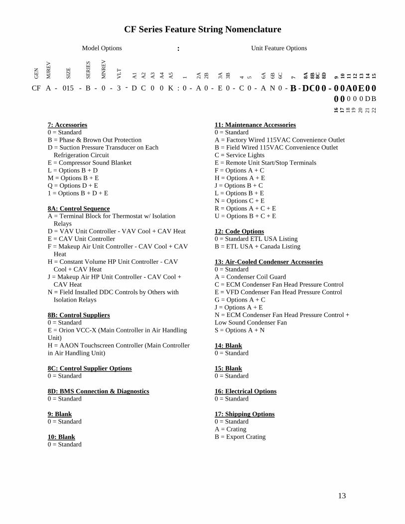
CF Series Feature String Nomenclature
Model Options Unit Feature Options
GE
N
MJR
EV
SIZ
E
SE
RIE
S
MN
RE
V
VL
T
A1
A2
A3
A4
A5
1
2A
2B
3A
3B
4
5
6A
6B
6C
7
8A
8B
8
C
8D
9
10
11
12
13
14
15
CF A - 015 - B - 0 - 3 - D C 0 0 K 0 - A 0 - E 0 - C 0 - A N 0 - B - D C 0 0 - 0 0 A 0 E 0 0 0 0 0 0 0 D B
16
17
18
19
20
21
22
13
7 Accessories
0 = Standard
B = Phase amp Brown Out Protection
D = Suction Pressure Transducer on Each
Refrigeration Circuit
E = Compressor Sound Blanket
L = Options B + D
M = Options B + E
Q = Options D + E
1 = Options B + D + E
8A Control Sequence
A = Terminal Block for Thermostat w Isolation
Relays
D = VAV Unit Controller - VAV Cool + CAV Heat
E = CAV Unit Controller
F = Makeup Air Unit Controller - CAV Cool + CAV
Heat
H = Constant Volume HP Unit Controller - CAV
Cool + CAV Heat
J = Makeup Air HP Unit Controller - CAV Cool +
CAV Heat
N = Field Installed DDC Controls by Others with
Isolation Relays
8B Control Suppliers
0 = Standard
E = Orion VCC-X (Main Controller in Air Handling
Unit)
H = AAON Touchscreen Controller (Main Controller
in Air Handling Unit)
8C Control Supplier Options
0 = Standard
8D BMS Connection amp Diagnostics
0 = Standard
9 Blank
0 = Standard
10 Blank
0 = Standard
11 Maintenance Accessories
0 = Standard
A = Factory Wired 115VAC Convenience Outlet
B = Field Wired 115VAC Convenience Outlet
C = Service Lights
E = Remote Unit StartStop Terminals
F = Options A + C
H = Options A + E
J = Options B + C
L = Options B + E
N = Options C + E
R = Options A + C + E
U = Options B + C + E
12 Code Options
0 = Standard ETL USA Listing
B = ETL USA + Canada Listing
13 Air-Cooled Condenser Accessories
0 = Standard
A = Condenser Coil Guard
C = ECM Condenser Fan Head Pressure Control
E = VFD Condenser Fan Head Pressure Control
G = Options A + C
J = Options A + E
N = ECM Condenser Fan Head Pressure Control +
Low Sound Condenser Fan
S = Options A + N
14 Blank
0 = Standard
15 Blank
0 = Standard
16 Electrical Options
0 = Standard
17 Shipping Options
0 = Standard
A = Crating
B = Export Crating
CF Series Feature String Nomenclature
Model Options Unit Feature Options G
EN
MJR
EV
SIZ
E
SE
RIE
S
MN
RE
V
VL
T
A1
A2
A3
A4
A5
1
2A
2B
3A
3B
4
5
6A
6B
6C
7
8A
8B
8C
8D
9
10
11
12
13
14
15
CF A - 015 - B - A - 3 - D C 0 0 K 0 - A 0 - E 0 - C 0 - A N 0 - B - D E 0 0 - 0 0 A 0 E 0 0
0 0 0 0 0 D B 1
6
17
18
19
20
21
22
14
18 Blank
0 = Standard
19 Blank
0 = Standard
20 Cabinet Material
0 = Galvanized Steel Cabinet
21 Warranty
0 = Standard
D = Compressor Warranty - Years 2-5
22 Type
B = Premium AAON Gray Paint Exterior
E = Premium AAON Gray Paint Ext + Shrink Wrap
X = SPA + Premium AAON Gray Paint Exterior
1 = SPA + Premium AAON Gray Paint Exterior +
Shrink Wrap
15
General Information
AAON CF Series air-cooled condensers and
condensing units have been designed for
outdoor use only They are factory
assembled wired charged and run-tested
Codes and Ordinances
CF Series units have been tested and
certified by ETL in accordance with UL
Safety Standard 1995CSA C222 No 236
System should be sized in accordance with
the American Society of Heating
Refrigeration and Air Conditioning
Engineers Handbook
Installation of CF Series units must conform
to the ICC standards of the International
Mechanical Code the International Building
Code and local building plumbing and
electrical codes All appliances must be
electrically grounded in accordance with
local codes or in the absence of local codes
the current National Electric Code
ANSINFPA 70 or the current Canadian
Electrical Code CSA C221
Receiving Unit
When received the unit should be checked
for damage that might have occurred in
transit If damage is found it should be noted
on the carrierrsquos freight bill A request for
inspection by carrierrsquos agent should be made
in writing at once Nameplate should be
checked to ensure the correct model sizes and
voltages have been received to match the job
requirements
If repairs must be made to damaged goods
then the factory should be notified before any
repair action is taken in order to protect the
warranty Certain equipment alteration
repair and manipulation of equipment
without the manufacturerrsquos consent may void
the product warranty Contact AAON
Technical Support for assistance with
handling damaged goods repairs and freight
claims (918) 382-6450
SHARP EDGES
Coils and sheet metal surfaces present sharp edges and care must be taken when working with equipment
WARNING
QUALIFIED INSTALLER
Improper installation adjustment alteration service or maintenance can cause property damage personal injury or loss of life Installation and service must be performed by a Factory Trained Service Technician
WARNING
Failure to observe the following instructions will result in premature failure of your system and possible voiding of the warranty
WARNING
16
Storage
If installation will not occur immediately
following delivery store equipment in a dry
protected area away from construction traffic
and in the proper orientation as marked on the
packaging with all internal packaging in
place Secure all loose-shipped items
Failure to observe the following instructions
will result in premature failure of your
system and possible voiding of the warranty
Never turn off the main power supply to the
unit except for complete shutdown When
power is cut off from the unit any
compressors using crankcase heaters cannot
prevent refrigerant migration This means the
compressor will cool down and liquid
refrigerant may accumulate in the
compressor The compressor is designed to
pump refrigerant gas and damage may occur
if liquid enters the compressor when power is
restored
Before unit operation the main power switch
must be turned on for at least twenty-four
hours for units with compressor crankcase
heaters This will give the crankcase heater
time to clear any liquid accumulation out of
the compressor before it is required to run
Always control the system from the control
panel never at the main power supply (except
for emergency or for complete shutdown of
the system)
CLEAN AIR ACT
The Clean Air Act of 1990 bans the intentional venting of refrigerant as of July 1 1992 Approved methods of recovery recycling or reclaiming must be followed
CAUTION
CRANKCASE HEATER OPERATION
Units are equipped with compressor crankcase heaters which should be energized at least 24 hours prior to cooling operation to clear any liquid refrigerant from the compressors
CAUTION
3-PHASE ROTATION
Rotation must be checked on all MOTORS AND COMPRESSORS of three phase units All motors to include and not be limited to pump motors and condenser fan motors should all be checked by a qualified service technician at startup and any wiring alteration should only be made at the unit power connection
CAUTION
17
The standard compressors must be on a
minimum of 5 minutes and off for a minimum
of 5 minutes The cycle rate must be no more
than 6 starts per hour
The variable capacity compressors must be
on a minimum of 3 minutes and off for a
minimum of 3 minutes The cycle rate must
be no more than 6 starts per hour
The compressor life will be seriously
shortened by reduced lubrication and the
pumping of excessive amounts of liquid oil
and liquid refrigerant
Wiring Diagrams
A complete set of unit specific wiring
diagram in point-to-point form is laminated
in plastic and located inside the control
compartment door
General Maintenance
When the initial startup is made and on a
periodic schedule during operation it is
necessary to perform routine service checks
on the performance of the condensing unit
This includes reading and recording suction
pressures and checking for normal sub-
cooling and superheat
COMPRESSOR ROTATION
Scroll compressors are directional and will be damaged by operation in the wrong direction Low pressure switches on compressors have been disconnected after factory testing Rotation should be checked by a qualified service technician at startup using suction and discharge pressure gauges and any wiring alteration should only be made at the unit power connection
COMPRESSOR CYCLING
5 MINUTE MINIMUM OFF TIME To prevent motor overheating compressors must cycle off for a minimum of 5 minutes
5 MINUTE MINIMUM ON TIME To maintain the proper oil level compressors must cycle on for a minimum of 5 minutes The cycle rate must not exceed 6 starts per hour
WARNING
CAUTION
18
Installation
Forklifting the Unit
CF Series condensing unit sizes 2-25 amp 30
tons can be lifted using a forklift 2-7 ton
units must have forks at least 48rdquo in length
9-25 amp 30 ton units must have forks 72rdquo in
length or the forks must have 72rdquo fork
extensions Standard units can be lifted from
all sides except the condenser coil side CF
Series condensing unit sizes 26 amp 31-70 tons
cannot be lifted using a forklift They can be
lifted as shown in Figure 3
Forks must be perpendicular to the unit and
they must be in far enough that the back of
the forks are no more than 6rdquo away from the
edge of the unit
Figure 1 - Forklifting a CF Series A Cabinet
Figure 2 - Forklifting a CF Series B and C
Cabinet
FORKLIFTING 2-7 TON UNITS
Forks or Fork Extensions must be at least 48rdquo in length
CAUTION
FORKLIFTING 9-25 amp 30 TON UNITS
Forks or Fork Extensions must be at least 72rdquo in length
CAUTION
19
Lifting the Unit
If cables or chains are used to hoist the unit
they must be the same length Minimum
cable length is 99rdquo for CF Series 9-70 ton
units CF Series 2-7 ton units do not include
factory installed lifting lugs and should be
lifted by forklift only Care should be taken
to prevent damage to the cabinet coils and
condenser fans
Before lifting unit be sure that all shipping
material has been removed from unit Secure
hooks and cables at all lifting points lugs
provided on the unit
Figure 3 ndash Lifting Details and Orientation of
a CF Series 9-70 ton Condensing Unit
Locating the Unit
The CF Series condenser and condensing unit
is designed for outdoor applications and
mounting at ground level or on a rooftop It
must be placed on a level and solid
foundation that has been prepared to support
its weight When installed at ground level a
one-piece concrete slab should be used with
footings that extend below the frost line Also
with ground level installation care must be
taken to protect the coil fins from damage due
to vandalism or other causes
The first clearance table below gives the
clearance values for proper unit operation
The second clearance table gives the
clearance necessary for removing the coil
without disassembling a large part of the
condensing unit For ease of removing the
condenser coil use the second table
clearances for the right hand side of the unit
Table 1 ndashClearances for Proper Operation
Location Unit Size
2-7 tons 9-70 tons
Front -
(Controls
Side)
Unobstructed 36rdquo
Left Side 6rdquo 30rdquo
Right Side 6rdquo 36rdquo
Top 3rdquo Unobstructed
Back 18rdquo 6rdquo
Table 2 ndash Clearances for Coil Pull
Unit Size Right Hand Side
2-7 tons 42rdquo
9-15 tons 42rdquo
16-25 amp 30 tons 54rdquo
26 amp 31-70 tons 66rdquo
Figure 4 - Orientation of Series 2-7 ton
Condensing Unit
20
The placement relative to the building air
intakes and other structures must be carefully
selected Airflow to and from the condenser
or condensing unit must not be restricted to
prevent a decrease in performance and
efficiency
The installation position for 9-70 ton units
must provide at least 30rdquo of left and right side
clearance for proper airflow to the condenser
coils When units are mounted adjacent to
each other the minimum right and left side
clearance required between the units is 60rdquo or
5 feet Similarly when 2-7 ton units are
mounted adjacent to each other the minimum
clearance required between the back side of
the units is 36rdquo or 3 feet
Units should not be installed in an enclosure
or pit that is deeper than the height of the unit
When recessed installation is necessary the
clearance to maintain proper airflow is at
least 5 feet (3 feet for 2-7tons)
CF Series condensers and condensing units
that have a vertical air discharge must have
no obstruction above the equipment Do not
place the unit under an overhang CF Series
condensers and condensing units that have a
horizontal discharge must have no
obstruction in front of the unit
For proper unit operation the immediate area
around condenser must remain free of debris
that may be drawn in and obstruct airflow in
the condensing section
Consideration must be given to obstruction
caused by snow accumulation when placing
the unit
Mounting Isolation
For roof mounted applications or anytime
vibration transmission is a factor vibration
isolators may be used
Access Doors
Access doors are provided to the compressor
and electrical compartment
Standard Evacuation Instructions
Proper system evacuation is critical to
remove moisture and non-condensables from
the system before charging the system with
refrigerant A newly installed AAON
condensing unit has already been evacuated
and charged with some refrigerant at the
factory When evacuating a new system
keep the condensing unit service valves
closed and evacuate the suction and liquid
lines and the air handling unit If the entire
system must be evacuated use the following
procedure to ensure the entire system is
pulled into a good vacuum
1 System evacuation should be
performed anytime a system is open to
atmospheric pressure The POE oils
used with R-410A are extremely
hydroscopic in nature and immediately
begin pulling in moisture once the
system is opened to the atmosphere
2 Before starting to evacuate the
system you MUST ensure that there are
no leaks by pressurizing the system with
PVC PIPING
PVC (Polyvinyl Chloride) and CPVC (Chlorinated Polyvinyl Chloride) are vulnerable to attack by certain chemicals Polyolester (POE) oils used with R-410A and other refrigerants even in trace amounts in a PVC or CPVC piping system will result in stress cracking of the piping and fittings and complete piping system failure
CAUTION
21
400 psig of dry nitrogen and verifying no
pressure loss after one hour
3 Four valve manifold gauge sets are
more effective than standard manifold
gauge sets due to the extra hose port in
combination with a 38rsquorsquo evacuation
port The larger diameter evacuation port
will expedite system evacuation
4 The manifold set should be connected
to the condensing unit with one hose on
the suction line service valve one hose
on the liquid line service valve and if an
extra Schrader valve is field installed on
the suction line connect a third hose (not
shown) The vacuum pump should be
connected to the manifold set using a
38rdquo vacuum rated hose Figure 5 shows
two circuits Both circuits must be
evacuated separately
Figure 5 ndash CU evacuation connections
5 An accurate micron gauge must be
used and checked by pulling a vacuum
on the gauge by itself and verify a rapid
drop to less than 100 microns within a
few minutes
6 The micron gauge should not be
attached to the system until the gauge
manifold is reading 28rsquorsquo of vacuum to
ensure the micron gauge does not see
pressure and is thus damaged MICRON
GAUGES WILL BE DAMAGED BY
PRESSURE
7 It is a good practice to replace the
vacuum pump oil after one hour of the
evacuation process The oil can be
broken down in the pump in the initial
first hour causing system evacuation to
take longer than it should
8 The minimum micron level required
by AAON is 350 microns for systems
using POE oils
9 The system should then be isolated
and the pump turned off to check for
vacuum rise due to leaks or moisture in
the system The micron gauge should
not rise above 500 microns after 30
minutes of wait time
Low Ambient amp Modulating Reheat
System Evacuation Instructions
Proper system evacuation is critical to
remove moisture and non-condensables from
the system before charging the system with
refrigerant Systems with low ambient
flooded condenser option require the
following procedure to ensure the entire
system is pulled into a good vacuum
1 System evacuation should be
performed anytime a system is open to
atmospheric pressure The POE oils
used with R-410A are extremely
hydroscopic in nature and immediately
begin pulling in moisture once the
system is opened to the atmosphere
2 Open the reheat valve to 50 when
evacuating
3 Before starting to evacuate the
system you MUST ensure that there are
no leaks by pressurizing the system with
22
400 psig of dry nitrogen and verifying no
pressure loss after one hour
4 Four valve manifold gauge sets are
more effective than standard manifold
gauge sets due to the extra hose port in
combination with a 38rsquorsquo evacuation
port The larger diameter evacuation port
will expedite system evacuation
5 The manifold set should be connected
to the condensing unit with one hose on
the suction line service valve one hose
on the liquid line service valve and a
third hose on the reheat line service
valve The vacuum pump should be
connected to the manifold set using a
38rdquo vacuum rated hose Figure 6 shows
two circuits The first circuit has a
reheat line the second circuit is just the
suction and liquid line Both circuits
must be evacuated separately
Figure 6 ndash CU evacuation connections
6 FAILURE to connect to the liquid
line service valve will result in the
receiver tank not being fully evacuated
and most likely lead to non-
condensables in the system
7 An accurate micron gauge must be
used and checked by pulling a vacuum
on the gauge by itself and verify a rapid
drop to less than 100 microns within a
few minutes
8 The micron gauge should not be
attached to the system until the gauge
manifold is reading 28rsquorsquo of vacuum to
ensure the micron gauge does not see
pressure and is thus damaged MICRON
GAUGES WILL BE DAMAGED BY
PRESSURE
9 It is a good practice to replace the
vacuum pump oil after one hour of the
evacuation process The oil can be
broken down in the pump in the initial
first hour causing system evacuation to
take longer than it should
10 The minimum micron level required
by AAON is 350 microns for systems
using POE oils
11 The system should then be isolated
and the pump turned off to check for
vacuum rise due to leaks or moisture in
the system The micron gauge should
not rise above 500 microns after 30
minutes of wait time
Adjusting Refrigerant Charge
All AAON CF Series condensers and
condensing units are shipped with a factory
holding charge The factory charge is
different depending on the unit size and
system (heat pump modulating hot gas
reheat LAC) The factory charge per circuit
is shown on the unit nameplate Adjusting the
charge of the system will be required during
installation
23
Adjusting the charge of a system in the field
must be based on determination of liquid sub-
cooling and evaporator superheat On a
system with a thermostatic expansion valve
liquid sub-cooling is more representative of
the charge than evaporator superheat but both
measurements must be taken
Before Charging
Refer to the Unit Nameplate to determine
which refrigerant must be used to charge the
system
Unit being charged must be at or near full
load conditions before adjusting the charge
Units equipped with hot gas bypass must
have the hot gas bypass valve closed to get
the proper charge
Units equipped with hot gas reheat must be
charged with the hot gas valve closed while
the unit is in cooling mode After charging
unit should be operated in reheat
(dehumidification) mode to check for correct
operation
Units equipped with heat pump options
should be charged in cooling mode to get the
proper charge After charging unit should be
operated in heating mode to check for correct
charge Charge may need to be adjusted for
heating mode If adjustments are made in the
heating mode cooling mode must be rerun to
verify proper operation
After adding or removing charge the system
must be allowed to stabilize typically 10-15
minutes before making any other
adjustments
The type of unit and options determine the
ranges for liquid sub-cooling and evaporator
superheat Refer to Table 3 when determining
the proper sub-cooling
For units equipped with low ambient (0degF)
option see the special charging instructions at
the end of this section
Checking Liquid Sub-cooling
Measure the temperature of the liquid line as
it leaves the condenser coil
Read the gauge pressure at the liquid line
close to the point where the temperature was
taken You must use liquid line pressure as it
will vary from discharge pressure due to
condenser coil pressure drop
Convert the pressure obtained to a saturated
temperature using the appropriate refrigerant
temperature-pressure chart
COMPRESSOR LUBRICANT
Polyolester (POE) and Polyvinylether (PVE) oils are two types of lubricants used in hydrofluorocarbon (HFC) refrigeration systems Refer to the compressor label for the proper compressor lubricant type
CAUTION
CLEAN AIR ACT
The Clean Air Act of 1990 bans the intentional venting of refrigerant (CFCrsquos and HCFCrsquos) as of July 1 1992 Approved methods of recovery recycling or reclaiming must be followed Fines andor incarceration may be levied for non-compliance
CAUTION
24
Subtract the measured liquid line temperature
from the saturated temperature to determine
the liquid sub-cooling
Compare calculated sub-cooling to Table 3
for the appropriate unit type and options
Table 3 - Acceptable Refrigeration Circuit
Values
Cooling
Mode
Liquid Sub-
Cooling
Values
Cooling Only Unit4 8-15degF
Cooling Only Unit with Hot
Gas Reheat14 5-15degF
Heat PumpUnit24 2-4degF
Heat Pump Unit with Hot
Gas Reheat34 2-6degF
Cooling Only Unit with
LAC4 8-15degF
Cooling Only Unit with Hot
Gas Reheat amp LAC4 8-15degF
Notes 1 Must be charged with the hot gas valve
closed After charging unit should be
operated in reheat (dehumidification) mode
to check for correct operation
2 The sub-cooling value in this table is for the
unit running in cooling mode of operation
After charging unit should be operated in
heating mode to check for correct operation
3 The sub-cooling value in this table is for the
unit running in cooling mode of operation
and the hot gas valve closed After charging
unit should be operated in reheat
(dehumidification) mode to check for correct
operation and then in heating mode to check
for correct operation
4 Sub-cooling must be increased by 1degF per 10
feet of vertical liquid line rise for R-410A
(AHU above CU) For example a cooling
only unit with hot gas reheat and a vertical
liquid drop can charge to a sub-cooling value
of 5-15degF but a cooling only unit with hot
gas reheat and a vertical liquid rise of 30 ft
must charge to a sub-cooling value of at least
8-15degF DO NOT OVERCHARGE
Refrigerant overcharging leads to excess
refrigerant in the condenser coils resulting in
elevated compressor discharge pressure
Checking Evaporator Superheat
Measure the temperature of the suction line
close to the compressor
Read gauge pressure at the suction line close
to the compressor
Convert the pressure obtained to a saturated
temperature using the appropriate refrigerant
temperature-pressure chart
Subtract the saturated temperature from the
measured suction line temperature to
determine the evaporator superheat
For refrigeration systems with tandem
compressors it is critical that the suction
superheat setpoint on the TXV is set with one
compressor running The suction superheat
should be 10-13degF with one compressor
running The suction superheat will increase
with both compressors in a tandem running
Inadequate suction superheat can allow liquid
refrigerant to return to the compressors which
will wash the oil out of the compressor Lack
of oil lubrication will destroy a compressor
Liquid sub-cooling should be measured with
both compressors in a refrigeration system
running
Compare calculated superheat to the
acceptable cooling mode superheat values of
8-15degF for all system types Superheat will
increase with long suction line runs
25
Adjusting Sub-cooling and Superheat
Temperatures
The system is overcharged if the sub-cooling
temperature is too high compared to Table 3
and the evaporator is fully loaded (low loads
on the evaporator result in increased sub-
cooling) and the evaporator superheat is
within the temperature range of 8-15degF (high
superheat results in increased sub-cooling)
Correct an overcharged system by reducing
the amount of refrigerant in the system to
lower the sub-cooling
The system is undercharged if the superheat
is too high and the sub-cooling is too low
Correct an undercharged system by adding
refrigerant to the system to reduce superheat
and raise sub-cooling
If the sub-cooling is correct and the superheat
is too high the TXV may need adjustment to
correct the superheat
DO NOT OVERCHARGE Refrigerant overcharging leads to excess refrigerant in the condenser coils resulting in elevated compressor discharge pressure
CAUTION
EXPANSION VALVE ADJUSTMENT
Thermal expansion valves must be adjusted to approximately 8-15degF of suction superheat Failure to have sufficient superheat will damage the compressor and void the warranty
CAUTION
26
Special Low Ambient Option Charging
Instructions
For units equipped with low ambient
refrigerant flood back option being charged
in the summer when the ambient
temperature is warm
If the ambient is above 70degF charge to
approximately 1-2degF of sub-cooling
measured at the inlet to the expansion valve
Once enough charge has been added to get
the evaporator superheat and sub-cooling
values to the correct setting more charge
must be added Use Table 4 to find the
additional charge amount required for the
system when running in cold ambient
conditions
Table 4 ndash Charge to Flood Condenser Coil
for Ambient Above 70degF
CF Size of
circuits
Per Circuit
Charge (lbs)
CF 2 3 1 49
CF 4 5 6 7 1 92
CF 9 11 2 91
CF 13 15 2 121
CF 16 18 2 131
CF 20 25 30 2 175
CF 26 31 40 2 180
4 91
CF 50 60 70 2 438
4 221
For units equipped with low ambient
refrigerant flood back option being charged
in the winter when the ambient
temperature is cold
1 If the ambient is below 70degF charge
to approximately 1-2degF of sub-cooling
measured at the inlet to the expansion
valve Once enough charge has been
added to get the evaporator superheat
and sub-cooling values to the correct
setting more charge may need to be
added If the ambient temperature is 0degF
no more charge is required Ambient
temperatures above 0degF will require a
percentage of the per circuit charge
values from Table 4 Using your
ambient temperature find the
percentage value from Table 5 and
multiply the Per Circuit Charge value
from Table 4 and the value to
determine the additional charge amount
Table 5 ndash Charge to Flood Condenser
Coil for Ambient Below 70degF
Condenser
Ambient
Temperature ˚F
Percentage
Per Circuit
Charge from
Table 4
60 60
50 37
40 24
30 15
20 8
0 0
2 The unit should be checked for proper
operation once the ambient temperature
is above 80degF
Example A CF size 31 with tandem
compressors where the ambient
temperature is 40degF
From Table 4 ndash 18 lbs refrigerant charge
per circuit (tandem compressors would
have 2 circuits in this size of CF)
From Table 5 ndash 24 of Table 4 charge
Additional charge needed for a unit with
low ambient flooded condenser controls
= 18 lbs 024 = 432 lbs additional
refrigerant charge per circuit
27
Low Ambient Operation
During low ambient temperatures the vapor
refrigerant will migrate to the cold part of the
system and condense into liquid All CF
Series compressors are provided with factory
installed crankcase heaters to help prevent
liquid refrigerant from slugging the
compressors during startup in low ambient
conditions The condenser or condensing unit
must have continuous power 24 hours prior
to startup This ensures the compressor will
receive sufficient refrigerant vapor at startup
Standard units can operate down to 55degF
ambient temperature
AAON condenser fan head pressure control
units can operate down to 35degF ambient
temperature Three different condenser fan
head pressure control options available are
adjustable fan cycling ECM condenser fan
or VFD controlled condenser fans See
detailed information following
The AAON low ambient (condenser flood-
back) system is used to operate a refrigerant
system down to 0degF outside air temperature
See detailed information following
Fan Cycling Low Ambient
Adjustable fan cycling is a low ambient head
pressure control option that cycles the
condenser fans to maintain refrigerant circuit
head pressures at acceptable levels during
cooling operation The head pressure set
point (100-470 psi) and pressure differential
(35-200 psi) can be field adjusted using a
flathead screwdriver For example if the
head pressure is set to 300psi and the
differential is set to 100psi then fans will cut
in at 300psi and cut out at 200psi Fan
cycling and variable speed condenser fan
head pressure control options allow
mechanical cooling with ambient
temperatures down to 35degF
Figure 7 - Adjustable Fan Cycling Switch
Variable Speed Low Ambient
Variable speed condenser fan head pressure
control is a low ambient head pressure
control option that sends a variable signal in
relation to the refrigerant circuit head
pressure of the system to an electronically
commutated motor (ECM) or VFD The
motor either speeds up or slows down air
flow accordingly in order to maintain
constant head pressure Fan cycling and
variable speed condenser fan head pressure
control options allow mechanical cooling
with ambient temperatures down to 35degF
Flooded Condenser Low Ambient
Flooded condenser low ambient control
maintains normal head pressure during
periods of low ambient When the ambient
temperature drops the condensing
temperature and therefore pressure drops
Without ambient control the system would
shut down on low discharge pressure The
flooded condenser method of low ambient
control fills the condenser coil with liquid
refrigerant decreasing the heat transfer
capacity of the coil which allows the coil to
operate at an acceptable discharge pressure
28
The condenser coil will not be flooded during
summer ambient temperatures so a receiver
is included to store the additional liquid
refrigerant required to flood the condenser
coil in low ambient The receiver is factory-
sized to contain all of the flooded volume
Without a receiver there would be high head
pressures during higher ambient conditions
The low ambient system maintains normal
head pressure during periods of low ambient
by restricting liquid flow from the condenser
to the receiver and at the same time
bypassing hot gas around the condenser to the
inlet of the receiver This reduces liquid
refrigerant flow from the condenser reducing
its effective surface area which in turn
increases the condensing pressure At the
same time the bypassed hot gas raises liquid
pressure in the receiver allowing the system
to operate properly CF Series condensers
and condensing units use an LAC valve for
low ambient operation
LAC Valve
The Low Ambient Control (LAC) valve is a
non-adjustable three way valve that
modulates to maintain receiver pressure As
the receiver pressure drops below the valve
setting (295 psig for R-410A) the valve
modulates to bypass discharge gas around the
condenser The discharge gas warms the
liquid in the receiver and raises the pressure
to the valve setting The following schematic
shows an example system using the LAC
valve
Figure 8 ndash LAC Piping Example
29
Refrigerant Piping
(See back of the manual for refrigerant piping
diagrams)
General
Piping from the condensing unit to the air
handler is the responsibility of the installing
contractor
Use only clean type ldquoACRrdquo copper tubing
that has been joined with high temperature
brazing alloy
The pipe or line sizes must be selected to
meet the actual installation conditions and
NOT simply based on the connection sizes at
the condensing unit or air handler
All CF Series condensing units are provided
with in-line shutoff valves on both the liquid
and suction lines These should remain closed
until the system is ready for start-up after
installation
Piping should conform to generally accepted
practices and codes
Care must be taken not to cross the circuits
on multiple circuit systems
Upon completion of piping connection the
interconnecting piping and air handler MUST
BE evacuated to 500 microns or less leak
checked and charged with refrigerant
Determining Refrigerant Line Size
The piping between the condenser and low
side must ensure
1 Minimum pressure drop and
2 Continuous oil return and
3 Prevention of liquid refrigerant slugging
or carryover
Minimizing the refrigerant line size is
favorable from an economic perspective
reducing installation costs and reducing the
potential for leakage However as pipe
diameters decrease pressure drop increases
Excessive suction line pressure drop causes
loss of compressor capacity and increased
power usage resulting in reduced system
efficiency Excessive pressure drops in the
liquid line can cause the liquid refrigerant to
flash resulting in faulty TXV operation and
improper system performance In order to
operate efficiently and cost effectively while
avoiding malfunction refrigeration systems
must be designed to minimize both cost and
pressure loss
REFRIGERANT PIPING
Line sizes must be selected to meet actual installation conditions not simply based on the connection sizes at the condensing unit or air handling unit
CAUTION
REFRIGERANT PIPING
This section is for information only and is not intended to provide all details required by the designer or installer of the refrigerant piping between the condenser or condensing unit and the air handling unit AAON Inc is not responsible for interconnecting refrigerant piping Consult ASHRAE Handbook ndash Refrigeration and ASME Standards
CAUTION
30
Equivalent Line Length
All line lengths discussed in this manual
unless specifically stated otherwise are
Equivalent Line Lengths The frictional
pressure drop through valves fittings and
accessories is determined by establishing the
equivalent length of straight pipe of the same
diameter Always use equivalent line
lengths when calculating pressure drop
Special piping provisions must be taken
when lines are up vertical risers or in
excessively long line runs AAON does not
recommend running underground
refrigerant lines
Liquid Line
When sizing the liquid line it is important to
minimize the refrigerant charge to reduce
installation costs and improve system
reliability This can be achieved by
minimizing the liquid line diameter
However reducing the pipe diameter will
increase the velocity of the liquid refrigerant
which increases the frictional pressure drop
in the liquid line and causes other
undesirable effects such as noise
Maintaining the pressure in the liquid line is
critical to ensuring sufficient saturation
temperature avoiding flashing upstream of
the TXV and maintaining system efficiency
Pressure losses through the liquid line due to
frictional contact installed accessories and
vertical risers are inevitable Maintaining
adequate sub-cooling at the condenser to
overcome these losses is the only method to
ensure that liquid refrigerant reaches the
TXV
Liquid refrigerant traveling upwards in a riser
loses head pressure If the evaporator is
below the condenser with the liquid line
flowing down the gravitational force will
increase the pressure of the liquid refrigerant
This will allow the refrigerant to withstand
greater frictional losses without the
occurrence of flashing prior to the TXV
A moisture-indicating sight glass may be
field installed in the liquid line to indicate the
occurrence of premature flashing or moisture
in the line The sight glass should not be used
to determine if the system is properly
charged Use temperature and pressure
measurements to determine liquid sub-
cooling not the sight glass
Liquid Line Routing
Care should be taken with vertical risers
When the system is shut down gravity will
pull liquid down the vertical column and
back to the condenser when it is below the
evaporator This could potentially result in
compressor flooding A check valve can be
installed in the liquid line where the liquid
column rises above the condenser to prevent
this The liquid line is typically pitched along
with the suction line or hot gas line to
minimize the complexity of the
configuration
Liquid Line Insulation
In cooling only systems when the liquid line
is routed through regions where temperature
losses are expected no insulation is required
as this may provide additional sub-cooling to
the refrigerant When routing the liquid line
through high temperature areas insulation of
the line is appropriate to avoid loss of sub-
cooling through heat gain
In heat pump systems when the liquid line is
routed through regions where temperature
losses are expected (all lines exposed to
outside air conditions) insulate with a
minimum 1 inch thick Armaflex insulation
as this will prevent capacity loss during
heating mode of operation
31
Liquid Line Guidelines
In order to ensure liquid at the TXV the sum
of frictional losses and pressure loss due to
vertical rise must not exceed available sub-
cooling A commonly used guideline to
consider is a system design with pressure
losses due to friction through the line not to
exceed a corresponding 1-2degF change in
saturation temperature An additional
recommendation is that the sum of frictional
losses (including valve losses filter drier
losses other accessories and line losses) and
pressure loss due to vertical rise should not
exceed 8degF if the available sub-cooling is
10degF
If the velocity of refrigerant in the liquid line
is too great it could cause excessive noise or
piping erosion The recommended maximum
velocities for liquid lines are 100 fpm from
the condenser to a receiver to discourage
fluid backup and 500 fpm from receiver tank
to the evaporator (300 fpm if the line includes
an electric valve to minimize valve induced
liquid hammer)
Liquid Line Accessories
Liquid line shut off valves and filter driers are
factory provided The total length equivalent
of pressure losses through valves elbows and
fittings must be considered when adding
additional components in the field It is a
good practice to utilize the fewest elbows that
will allow the mating units to be successfully
joined
A liquid line receiver is factory installed on
units with modulating hot gas reheat units
with low ambient control flooded condenser
and units with heat pump
Suction Line
The suction line is more critical than the
liquid line from a design and construction
standpoint More care must be taken to
ensure that adequate velocity is achieved to
return oil to the compressor at minimum
loading conditions However reducing the
piping diameter to increase the velocity at
minimal load can result in excessive pressure
losses capacity reduction and noise at full
load
Suction Line Routing
For cooling only systems pitch the suction
line in the direction of flow (about 1 inch per
20 feet of length) to maintain oil flow
towards the compressor and keep it from
flooding back into the evaporator
For heat pump systems do not pitch lines
since they will be flowing in one direction in
cooling mode and the opposite direction in
heating mode
Crankcase heaters are provided to keep any
condensed refrigerant that collects in the
compressor from causing damage or wear
Make sure to provide support to maintain
suction line positioning and insulate
completely between the evaporator and
condensing unit
It is important to consider part load operation
when sizing suction lines At minimum
capacity refrigerant velocity may not be
adequate to return oil up the vertical riser
Decreasing the diameter of the vertical riser
will increase the velocity but also the
frictional loss
For difficult line routing applications a
double suction riser can be applied to the
situation of part load operation with a suction
riser A double suction riser is designed to
return oil at minimum load while not
incurring excessive frictional losses at full
load A double suction riser consists of a
small diameter riser in parallel with a larger
diameter riser and a trap at the base of the
large riser At minimum capacity refrigerant
velocity is not sufficient to carry oil up both
32
risers and it collects in the trap effectively
closing off the larger diameter riser and
diverting refrigerant up the small riser where
velocity of the refrigerant is sufficient to
maintain oil flow At full load the mass flow
clears the trap of oil and refrigerant is carried
through both risers The smaller diameter
pipe should be sized to return oil at minimum
load while the larger diameter pipe should be
sized so that flow through both pipes
provides acceptable pressure drop at full
load
Figure 9 - Double Suction Riser
Construction
A double riser can also be used for heat pump
operation The specific volume (ft3lb) of
refrigerant at the discharge temperature and
pressure (heating mode line conditions) is
significantly lower than the specific volume
at the suction temperature and pressure
(cooling mode line conditions) To
compound the issue the capacity in heating
mode is lower than the capacity in cooling
mode The discharge velocity in the riser
during heating mode is much lower than the
suction velocity during cooling mode Often
a double riser is necessary to get acceptable
velocities for the discharge mode and
acceptable velocities for the suction mode In
the example diagrams (See Figure 10 amp
Figure 11) the cooling mode will use both
lines and the heating mode will use only one
Suction Line Traps
Include a trap immediately after the
evaporator coil outlet to protect the TXV bulb
from liquid refrigerant
Include traps every 20 feet in vertical suction
riser sections for cooling only systems and
every 12 feet for heat pump systems
Suction Line Insulation
The entire suction line should be insulated
with a minimum 1 inch thick Armaflex
insulation This prevents condensation from
forming on the line and reduces any potential
loss in capacity associated with heat gain
placing additional load on the system This
line should still be insulated in heat pump
systems even though it acts as both a
discharge and suction line
Suction Line Guidelines
For proper performance suction line
velocities less than a 4000 fpm maximum are
recommended The minimum velocity
required to return oil is dependent on the pipe
diameter however a general guideline of
1000 fpm minimum may be applied
When suction flow is up variable capacity
compressors require a minimum velocity of
1500 fpm at full load
Tandem compressors must be considered for
full load operation (both compressors
operating) and at partial load (only one
compressor operating) When suction flow is
up and the tandem has a variable capacity
compressor the velocity for only one
compressor in operation must be greater than
1500 fpm For onoff compressors the
velocity must be greater than the minimum
velocity required to return oil
Heat pump vapor lines must be checked for
suction flow (cooling mode operation) and
discharge flow (heating mode operation)
33
The same line must be used for both modes
of operation
In a fashion similar to the liquid line a
common guideline to consider is a system
design with pressure losses due to friction
through the line not to exceed a
corresponding 1-2degF change in saturation
temperature
For split system piping with long horizontal
runs and short vertical risers a smaller pipe
size can be used to provide sufficient velocity
to return oil in vertical risers at part loads and
a larger size pipe can be used on the
horizontal runs and vertical drop sections
This helps with oil return yet keeps the
pressure drop to a minimum
Suction Line Accessories
If the job requirements specify suction
accumulators they must be separately
purchased and field installed Heat pump
units will include a factory installed suction
accumulator
Discharge Line
The discharge line is similar to the suction
line from a design and construction
standpoint Care must be taken to ensure that
adequate velocity is achieved to return oil to
the compressor at minimum loading
conditions However reducing the piping
diameter to increase the velocity at minimal
load can result in excessive pressure losses
capacity reduction and noise at full load
Pressure loss in the discharge line has less of
an impact on capacity than pressure loss in
the suction line Pressure loss in the
discharge line causes the compressors to
work harder and thus use more power
Discharge Line Routing
For cooling only remote condenser systems
pitch the discharge line in the direction of
flow (about 1 inch per 20 feet of length) to
maintain oil flow towards the compressor
In a heat pump system the field installed
suction line is also used as a discharge line in
the heating mode of operation so the line
must be sized to meet both the suction line
conditions in cooling mode and the discharge
line conditions in heating mode
Because it is used in both directions for a heat
pump unit the line should be installed level
not pitched to facilitate oil return in both
modes of operation
It is important to consider part load operation
when sizing discharge lines At minimum
capacity refrigerant velocity may not be
adequate to return oil up the vertical riser
Decreasing the diameter of the vertical riser
will increase the velocity but also the
frictional loss
For difficult line routing applications a
double discharge riser can be applied to the
situation of part load operation with a
discharge riser A double discharge riser is
designed to return oil at minimum load while
not incurring excessive frictional losses at
full load A double discharge riser consists of
a small diameter riser in parallel with a larger
diameter riser and a trap at the base of the
large riser At minimum capacity refrigerant
velocity is not sufficient to carry oil up both
risers and it collects in the trap effectively
closing off the larger diameter riser and
diverting refrigerant up the small riser where
SUCTION RISER TRAPS
Circuits require suction riser traps every 20 feet (every 12 feet for heat pumps)
CAUTION
34
velocity of the refrigerant is sufficient to
maintain oil flow At full load the mass flow
clears the trap of oil and refrigerant is carried
through both risers The smaller diameter
pipe should be sized to return oil at minimum
load while the larger diameter pipe should be
sized so that flow through both pipes
provides acceptable pressure drop at full
load (See the Double Suction Riser
Construction Figure 9)
A double riser can also be used for heat pump
operation The specific volume (ft3lb) of
refrigerant at the discharge temperature and
pressure (heating mode line conditions) is
significantly lower than the specific volume
at the suction temperature and pressure
(cooling mode line conditions) To
compound the issue the capacity in heating
mode is lower than the capacity in cooling
mode The discharge velocity in the riser
during heating mode is much lower than the
suction velocity during cooling mode Often
a double riser is necessary to get acceptable
velocities for the discharge mode and
acceptable velocities for the suction mode In
the example diagrams the cooling mode will
use both lines and the heating mode will use
only one See the following schematics that
illustrate how the double discharge riser can
work for heat pump applications
Figure 10 ndash Heat Pump Piping Schematic of
Cooling Mode in Double Riser
Figure 11 ndash Heat Pump Piping Schematic of
Heating Mode in Double Riser
35
Discharge Line Traps
Include traps every 12 feet in vertical
discharge riser sections
Discharge Line Insulation
Although a typical discharge line does not
need to be insulated the suction line does
Since the same line is used for both the line
must be insulated as described in the Suction
Line Insulation section
Discharge Line Guidelines
For proper performance discharge line
velocities less than a 3500 fpm maximum are
recommended The minimum velocity
required to return oil is dependent on the pipe
diameter however a general guideline of
900 fpm minimum may be applied
When discharge flow is up variable capacity
compressors require a minimum velocity of
900 fpm at full load
Tandem compressors must be considered for
full load operation (both compressors
operating) and at partial load (only one
compressor operating) When discharge flow
is up and the tandem has a variable capacity
compressor the velocity for only one
compressor in operation must be greater than
900 fpm For onoff compressors the
velocity must be greater than the minimum
velocity required to return oil
Heat pump vapor lines must be checked for
suction flow (cooling mode operation) and
discharge flow (heating mode operation)
The same line must be used for both modes
of operation
In a fashion similar to the suction line a
common guideline to consider is a system
design with pressure losses due to friction
through the line not to exceed a
corresponding 1-2degF change in saturation
temperature
For split system piping with long horizontal
runs and short vertical risers a smaller pipe
size can be used to provide sufficient velocity
to return oil in vertical risers at part loads and
a larger size pipe can be used on the
horizontal runs and vertical drop sections
This helps with oil return yet keeps the
pressure drop to a minimum
Hot Gas Bypass Line
Hot Gas Bypass is available for use with DX
systems that may experience low suction
pressure during the operating cycle This may
be due to varying load conditions associated
with VAV applications or units supplying a
large percentage of outside air The system is
designed to divert refrigerant from the
compressor discharge to the low pressure
side of the system in order to keep the
evaporator from freezing and to maintain
adequate refrigerant velocity for oil return at
minimum load
Hot discharge gas is redirected to the
evaporator inlet via an auxiliary side
connector (ASC) to false load the evaporator
when reduced suction pressure is sensed
Field piping between the condensing unit
and the evaporator is required
Hot Gas Bypass Piping Considerations
Pitch the hot gas bypass (HGB) line
downward in the direction of refrigerant
flow toward the evaporator
DISCHARGE RISER TRAPS
Circuits require discharge riser traps every 12 feet
CAUTION
36
When installing vertical hot gas bypass lines
an oil drip line must be provided at the lowest
point in the system The oil drip line must be
vertical its diameter should be the same as
the diameter of the riser and it should be
1 foot long Install a sight glass in the oil drip
line for observation Run an oil return line
using 18 inch capillary tube 10 feet in
length from the hot gas bypass line oil drip
line to the suction line Connect the oil return
line below the sight glass and 1 inch above
the bottom of the oil drip line
Figure 12 ndash Oil Return Line
HGB valves are adjustable Factory HGB
valve settings will be sufficient for most
applications but may require slight
adjustments for some applications including
some make up air applications
Insulate the entire length of the HGB line
with a minimum 1 inch thick Armaflex
insulation
Hot Gas Bypass Line Guidelines
Choose a small size line to ensure oil return
and minimize refrigerant charge
Maintain velocities below a maximum of
3500 fpm A general minimum velocity
guideline to use is approximately 2000 fpm
Hot Gas Reheat
The AAON modulating hot gas reheat system
diverts hot discharge gas from the condenser
to the air handling unit through the hot gas
line Field piping between the condensing
unit and the air handler is required
The line delivers the hot discharge gas to the
reheat coil andor the hot gas bypass valve so
it is sized as a discharge line
Discharge lines should be sized to ensure
adequate velocity of refrigerant to ensure oil
return avoid excessive noise associated with
velocities that are too high and to minimize
efficiency losses associated with friction
Pitch the hot gas line in the direction of flow
for oil return
When installing vertical hot gas reheat lines
an oil drip line must be provided at the lowest
point in the system The oil drip line must be
vertical its diameter should be the same as
the diameter of the riser and it should be
1 foot long Run an oil return line using 18
inch capillary tube 10 feet in length from the
hot gas reheat line oil drip line to the suction
line Connect the oil return line below the
sight glass and 1 inch above the bottom of the
oil drip line (See Oil Return Line Figure 12)
Insulate the entire length of the hot gas line
with a minimum 1 inch thick Armaflex
insulation
Hot Gas Reheat Guidelines
Maintain velocities below a maximum of
3500 fpm A general minimum velocity
guideline is 2000 fpm
37
Electrical
The single point electrical power connections
are made in the electrical control compartment
Verify the unit nameplate voltage agrees with
the power supply Connect power and control
field wiring as shown on the unit specific
wiring diagram provided with the unit
Table 6 - Nameplate Voltage Markings
Voltage Feature
Nameplate
Voltage
Marking
MinMax
VAC
1 230V1Φ60Hz 230 197252
2 230V3Φ60Hz 230 197252
3 460V3Φ60Hz 460 456504
4 575V3Φ60Hz 575 570630
8 208V3Φ60Hz 208 197228
9 208V1Φ60Hz 208 197228
NOTE Units are factory wired for 208V
230V 460V or 575V In some units the 208V
and 230V options may also be provided in
single or three phase configurations The
transformer configuration must be checked by
a qualified technician prior to startup
Size supply conductors based on the unit MCA
rating Supply conductors must be rated a
minimum of 167degF (75degC)
Route power and control wiring separately
through the utility entry Do not run power and
signal wires in the same conduit
Protect the branch circuit in accordance with
code requirements The unit must be
electrically grounded in accordance with local
codes or in the absence of local codes the
current National Electric Code ANSINFPA
70 or the current Canadian Electrical Code
CSA C221
Power wiring is to the unit terminal block or
main disconnect All wiring beyond this point
has been done by the manufacturer and cannot
be modified without affecting the units
agencysafety certification
Three phase voltage imbalance will cause
motor overheating and premature failure The
maximum allowable imbalance is 5
Voltage imbalance is defined as 100 times the
maximum deviation from the average voltage
divided by the average voltage
Example
(218V+237V+235V)3 = 230V then
100(230V-218V)230V = 52 which
exceeds the allowable imbalance
Check voltage imbalance at the unit disconnect
switch and at the compressor terminal
Contact your local power company for line
voltage corrections
3-PHASE ROTATION
Rotation must be checked on all MOTORS AND COMPRESSORS of three phase units Condenser fan motors should be checked by a qualified service technician at startup and any wiring alteration should only be made at the unit power connection Variable frequency drives are programmed to automatically rotate the fan in the correct rotation Do not rely on fans with variable frequency drives for compressor rotation
CAUTION
38
NOTE Startup technician must check for
proper motor rotation and check fan motor
amperage listed on the motor nameplate is not
exceeded Motor overload protection may be a
function of the variable frequency drive and
must not be bypassed
Wire control signals to the unitrsquos low voltage
terminal block located in the controls
compartment
If any factory installed wiring must be
replaced use a minimum 221degF (105degC) type
AWM insulated conductors
ELECTRIC SHOCK
Electric shock hazard Before attempting to perform any installation service or maintenance shut off all electrical power to the unit at the disconnect switches Unit may have multiple power supplies Failure to disconnect power could result in dangerous operation serious injury death or property damage
WARNING
SEALING ELECTRICAL ENTRIES
Installing Contractor is responsible for proper sealing of the electrical entries into the unit Failure to seal the entries may result in damage to the unit and property
CAUTION
39
Startup (See back of the manual for startup form)
Before startup of the condenser or condensing
unit make sure that the following items have
been checked
1 Verify that electrical power is available to
the unit
2 Verify that any remote stopstart device
connected to the unit controller is
requesting the unit to start
Cycle through all the compressors to confirm
that all are operating within tolerance
While performing the check use the startup
form to record observations of amps and
refrigerant pressures
When all is running properly place the
controller in the Run mode and observe the
system until it reaches a steady state of
operation
Compressor Operation
The compressors must be off for a minimum of
5 minutes and on for a minimum of 5 minutes
Short cycling of the compressors can cause
undue stress and wear
3-PHASE ROTATION
Rotation must be checked on all MOTORS AND COMPRESSORS of three phase units Condenser fan motors should all be checked by a qualified service technician at startup and any wiring alteration should only be made at the unit power connection Variable frequency drives are programmed to automatically rotate the fan in the correct rotation Do not rely on fans with variable frequency drives for compressor rotation
CAUTION
ELECTRIC SHOCK
Electric shock hazard Shut off all electrical power to the unit to avoid shock hazard or injury from rotating parts
WARNING
QUALIFIED INSTALLER
Improper installation adjustment alteration service or maintenance can cause property damage personal injury or loss of life Startup and service must be performed by a Factory Trained Service Technician
WARNING
Before completing installation a complete operating cycle should be observed to verify that all components are functioning properly
CAUTION
40
Variable Capacity Compressor Controller
Units with variable capacity scroll
compressors may include a variable capacity
compressor controller The following is an
explanation of the terminals and
troubleshooting of the alert flash codes on the
controller For more information on the
compressor controller see Emerson Climate
Bulletin AE8-1328
Figure 13 - Variable Capacity Compressor
Controller
Note When using field controls any variable
capacity compressors should run at 100 for 1
minute when starting
Low Voltage Terminals
24COM Module Common
24VAC Module Power
C1 Demand Input -
C2 Demand Input +
P1 Pressure Common
P2 Pressure Input
P3 Pressure Power 5VDC
P4 Pressure Shield
P5 Pressure Output -
P6 Pressure Output +
T1 amp T2 Discharge Temperature Sensor
High Voltage Terminals
A1 amp A2 Alarm Relay Out
M1 amp M2 Contactor
L1 Control Voltage N
L2 Control Voltage L
U1 amp U2 Variable Capacity Unloader Solenoid
V1 amp V2 Vapor Injection Solenoid
The compressor controller modulates the
compressor unloader solenoid in an onoff
pattern according the capacity demand signal
of the system The following table shows the
linear relationship between the demand signal
and compressor capacity modulation The
compressor controller also protects the
compressor against high discharge
temperature Refer to Table 8 for the
relationship between thermistor temperature
readings and resistance values
COMPRESSOR CONTROLLER
To avoid damaging the compressor controller DO NOT connect wires to terminals C3 C4 T3 T4 T5 or T6
WARNING
COMPRESSOR CYCLING
5 MINUTE MINIMUM OFF TIME To prevent motor overheating compressors must cycle off for a minimum of 5 minutes
5 MINUTE MINIMUM ON TIME To maintain the proper oil level compressors must cycle on for a minimum of 5 minutes The cycle rate must not exceed 6 starts per hour
WARNING
41
Table 7 - Demand Signal vs Compressor Capacity Modulation
Figure 14 - Compressor Controller Flash Code Details
Demand
Signal (VDC) Loaded Unloaded Time Loaded
Time
Unloaded
Compressor
Capacity
100 Off Off Off Off 0
144 10 90 15 sec 135 sec 10
300 50 50 75 sec 75 sec 50
420 80 20 12 sec 3 sec 80
500 100 0 15 sec 0 sec 100
42
Table 8 - Thermistor Temperature vs Resistance Values
degC degF kΩ degC degF kΩ
-40 -40 288960 75 167 1273
-35 -31 208722 80 176 1079
-30 -22 152220 85 185 920
-25 -13 112144 90 194 787
-20 -4 83472 95 203 677
-15 5 62728 100 212 585
-10 14 47574 105 221 509
-5 23 36399 110 230 445
0 32 28082 115 239 387
5 41 21841 120 248 335
10 50 17117 125 257 292
15 59 13514 130 266 258
20 68 10744 135 275 228
25 77 8600 140 284 202
30 86 6928 145 293 180
35 95 5616 150 302 159
40 104 4581 155 311 139
45 113 3758 160 320 125
50 122 3099 165 329 112
55 131 2568 170 338 101
60 140 2140 175 347 092
65 149 1791 180 356 083
70 158 1507
Compressor Lockouts
Some units include adjustable compressor
lockouts The compressor lockout in the
picture below can be set to any temperature
between -10degF and 70degF The ambient
temperature sensor hangs right outside the
unit with a cover
Figure 15 - Adjustable compressor lockout
Heat pump units include a non-adjustable
compressor lockout for the cooling mode set
to 55degF and an adjustable compressor
lockout for the heating mode that can be set
between 20degF to 95degF If a heat pump is
selected with the compressor lockout feature
the adjustable compressor lockout will
change to the -10degF to 70degF range
Figure 16 - Ambient sensor cover
43
Maintenance
General
Qualified technicians must perform routine
service checks and maintenance This
includes reading and recording the
condensing and suction pressures and
checking for normal sub-cooling and
superheat
Compressors
The scroll compressors are fully hermetic and
require no maintenance except keeping the
shell clean
Refrigerant Filter Driers
Each refrigerant circuit contains a filter drier
Replacement is recommended when there is
excessive pressure drop across the assembly
or moisture is indicated in a liquid line sight
glass
Table 9 - Max Filter Drier Pressure Drops
Circuit Loading Max Pressure Drop
100 10 psig
50 5 psig
Oil Level
It is critical that the refrigerant line piping is
designed to maintain proper oil return to the
compressors Some systems may require oil
to be added in addition to what is provided in
the compressors The oil is a POE type and
is available from your AAON Representative
under part number R63681
Proper oil level should be observed under
minimum load conditions On units equipped
with tandem compressors all oil is returned
to the lead compressor in each tandem pair
When only the lead compressor is running
the oil level should be a minimum of ⅜ from
the bottom of the sight glass With both
compressors running the level in the lead
compressor should drop to the bottom of the
sight glass and the level in the second
compressor should be a minimum of ⅜ from
the bottom of its sight glass Do not allow the
oil level in the sight glass to exceed frac34 full
level
44
Table 10 - R-410A Refrigerant Temperature-Pressure Chart
degF PSIG degF PSIG degF PSIG degF PSIG degF PSIG
20 783 47 1347 74 2137 101 3210 128 4632
21 800 48 1372 75 2171 102 3256 129 4693
22 818 49 1397 76 2206 103 3302 130 4754
23 836 50 1422 77 2241 104 3349 131 4816
24 854 51 1448 78 2277 105 3396 132 4878
25 872 52 1474 79 2313 106 3444 133 4941
26 891 53 1501 80 2349 107 3493 134 5005
27 910 54 1528 81 2386 108 3542 135 5069
28 929 55 1555 82 2423 109 3591 136 5134
29 949 56 1582 83 2460 110 3641 137 5200
30 968 57 1610 84 2498 111 3691 138 5266
31 988 58 1638 85 2537 112 3742 139 5333
32 1009 59 1667 86 2575 113 3794 140 5401
33 1029 60 1696 87 2614 114 3846 141 5470
34 1050 61 1725 88 2654 115 3899 142 5539
35 1071 62 1754 89 2694 116 3952 143 5609
36 1092 63 1784 90 2735 117 4005 144 5679
37 1114 64 1815 91 2776 118 4059 145 5751
38 1136 65 1845 92 2817 119 4114 146 5823
39 1158 66 1876 93 2859 120 4169 147 5896
40 1181 67 1907 94 2901 121 4225 148 5969
41 1203 68 1939 95 2944 122 4282 149 6044
42 1227 69 1971 96 2987 123 4339 150 6119
43 1250 70 2004 97 3030 124 4396
44 1274 71 2036 98 3075 125 4454
45 1298 72 2070 99 3119 126 4513
46 1322 73 2103 100 3164 127 4573
Lubrication
All original motors and bearings are
furnished with an original factory charge of
lubrication Certain applications require
bearings be re-lubricated periodically The
schedule will vary depending on operating
duty temperature variations or severe
atmospheric conditions
Bearings should be re-lubricated at normal
operating temperatures but not when
running
Condenser Tube Inspection
The coils are leak tested at 650 psig before
shipment AAON will not be responsible for
loss of refrigerant It is the responsibility of
the installer to verify that the system is sealed
before charging with refrigerant
Maintenance Recommendations
Fan Motor Maintenance
Cleaning - Remove oil dust water and
chemicals from exterior of motor Keep
motor air inlet and outlet open Blow out
45
interior of open motors with clean
compressed air at low pressure
Labeled Motors - It is imperative for repair of
a motor with Underwritersrsquo Laboratories
label that original clearances be held that all
plugs screws other hardware be fastened
securely and that parts replacements be exact
duplicates or approved equals Violation of
any of the above invalidates Underwritersrsquo
Label
Access Doors
If scale deposits or water is found around the
access doors adjust door for tightness
Adjust as necessary until leaking stops when
door is closed
Propeller Fans and Motors
The fans are directly mounted on the motor
shafts and the assemblies require minimal
maintenance except to assure they are clear
of dirt or debris that would impede the
airflow
Recommended Annual Inspection
In addition to the above maintenance
activities a general inspection of the unit
surface should be completed at least once a
year
Air-Cooled Condenser
The air-cooled condenser section rejects heat
by passing outdoor air over the fin tube coils
for cooling of the hot refrigerant gas from the
compressors
The condenser coils should be inspected
annually to ensure unrestricted airflow If the
installation has a large amount of airborne
dust or other material the condenser coils
should be cleaned with a water spray in a
direction opposite to airflow Care must be
taken to prevent bending of the aluminum
fins on the copper tubes
E-Coated Coil Cleaning
Documented quarterly cleaning of e-coated
coils is required to maintain coating warranty
coverage E-Coated Coil Maintenance
Record document is available on the AAON
website
Surface loaded fibers or dirt should be
removed prior to water rinse to prevent
restriction of airflow If unable to back wash
the side of the coil opposite of the coils
entering air side then surface loaded fibers or
dirt should be removed with a vacuum
cleaner If a vacuum cleaner is not available
a soft non-metallic bristle brush may be used
In either case the tool should be applied in
the direction of the fins Coil surfaces can be
easily damaged (fin edges bent over) if the
tool is applied across the fins
Use of a water stream such as a garden hose
against a surface loaded coil will drive the
fibers dirt and salts into the coil This will
make cleaning efforts more difficult Surface
loaded fibers must be completely removed
prior to using low velocity clean water rinse
Quarterly cleaning is required to maintain
warranty coverage and is essential to
maintain the life of an E-coated coil Coil
cleaning shall be part of the units regularly
scheduled maintenance procedures
ELECTRIC SHOCK
Electric shock hazard Shut off all electrical power to the unit to avoid shock hazard or injury from rotating parts
WARNING
46
Failure to clean an E-coated coil on the
prescribed quarterly cycle will void the
warranty and may result in reduced
efficiency and durability in the environment
A routine two-step quarterly coil cleaning is
required to maintain warranty
Step one is to clean the coil with the below
approved coil cleaner (see approved products
list under the Recommended Coil Cleanersrdquo
section
Step two is to use the approved saltchloride
remover under the Recommended Chloride
Removerrdquo section to dissolve soluble salts
and revitalize the unit It is very important
when cleaning andor rinsing not to exceed
130degF and potable water pressure is less than
100 psig to avoid damaging the unit and coil
fin edges
For routine quarterly cleaning first clean the
coil with the below approved coil
cleaner After cleaning the coils with the
approved cleaning agent use the approved
chloride remover to remove soluble salts and
revitalize the unit
Recommended Coil Cleaner ndash Step 1
GulfCoatTM Coil Cleaner assuming it is
used in accordance with the manufacturers
directions on the container for proper mixing
and cleaning has been approved for use on
E-coated coils to remove mold mildew dust
soot greasy residue lint and other
particulate Never use any cleaners that are
not approved
Recommended Chloride Remover ndash Step 2
CHLORRIDreg Concentrate assuming it
is used in accordance with the manufacturers
directions on the container for proper mixing
has been approved for use on E-coated coils
to remove chloridessalts amp sulfates Never
use any chloride removers that are not
approved
Warranty Protection ndash Step 1
Complete the coil cleaning following these
steps
1 Ensure that the power to the unit is off
and locked out
High velocity water from a pressure washer or compressed air should only be used at a very low pressure to prevent fin andor coil damages The force of the water or air jet may bend the fin edges and increase airside pressure drop Reduced unit performance or nuisance unit shutdowns may occur
Harsh chemicals household bleach or acid cleaners should not be used to clean e-coated coils These cleaners can be very difficult to rinse out of the coil and can accelerate corrosion and attack the e-coating If there is dirt below the surface of the coil use the recommended coil cleaners
CAUTION
CAUTION
47
2 Clean the area around the unit if
needed to ensure leaves grass or
loose debris will not be blown into the
coil
3 Remove panels or tops as required
gaining access to the coil(s) to be
cleaned
4 Using a pump up sprayer fill to the
appropriate level with potable water
and add the correct amount of
approved cleaner as per manufacture
instructions leaving room for the
pump plunger to be reinserted
NOTE Coils should always be cleaned
back flushed opposite of airflow to prevent
impacting the dirt into the coil
5 If the coils have heavy dirt fibers
grass leaves etc on the interior or
exterior face areas a vacuum and
brush should be used to remove those
surface contaminants prior to
applying cleaner The interior floor
drain tray or pan areas should also be
vacuumed
6 Apply the mixed cleaner to coil
surfaces using a pressurized pump up
sprayer maintaining a good rate of
pressure and at a medium size nozzle
spray (not a solid stream and not a
wide fan but somewhere in the
middle) Work in sectionspanels
ensuring that all areas are covered and
kept wetted
7 Apply the cleaner to unit interior air
exiting side coil surfaces first Work
in sectionspanels moving side to side
and from top to bottom
8 Generously soak coils by spraying
cleaner directly on and into the fin
pack section to be cleaned and allow
the cleaning solution to soak for 5 to
10 minutes
9 Using pressurized potable water
(lt100 psi) rinse the coils and
continue to always work in
sectionspanels Start at the top of the
coil and slowly move vertically
downward to the bottom Then
staying in the same vertical area
slowly move back up to the top where
you started Now move over slightly
overlapping the area just completed
and repeat above Continue until all
coil areas on the inside of the unit
have been rinsed
10 Complete steps 5-9 for the exterior air
entering side of the coils
11 Final rinse ndash Now complete a quick
rinse of both sides of the coil
including the headers piping
u-bends and hairpins
12 If the coil has a drain pan or unit floor
that is holding rinse water or cleaner
extra time and attention will need to
be taken in those areas to ensure a
proper rinse has been completed
Warranty Protection ndash Step 2
Complete the coil chloride (salt) removal
following these steps
1 CHLORRIDreg is a concentrate to be
used for both normal inland
applications at a 1001 mix ratio OR
for severe coastal applications 501
mix ratio with potable water
(256 ounces of Chlorrid to 1 gal of
water) Using a pump up sprayer fill
to the appropriate level with potable
water and add the correct amount of
CHLORRIDreg salt remover leaving
room for the pump plunger to be
reinserted
48
2 Apply CHLORRIDreg to all external
coil surfaces using a pressurized
pump up sprayer maintaining a good
rate of pressure and at a medium size
nozzle spray (not a solid stream and
not a wide fan but somewhere in the
middle) Work in sectionspanels
ensuring that all areas are covered and
kept wetted
3 Generously soak coils by spraying
CHLORRIDreg directly on and into
the fin pack section Let stand for 5 to
10 minutes keeping the area wetted
Do not allow to dry before rinsing
4 Using pressurized potable water
(lt100 psi) rinse the CHLORRIDreg
and dissolved chloridessalts off of
the coils continuing to always work in
sectionspanels
5 Starting at the top of the coil begin
rinsing the coil from side to side until
you reach the bottom Repeat as many
times as is necessary to ensure all coil
sectionspanels have been completed
and are thoroughly rinsed
6 Reinstall all panels and tops that were
removed
Service
If the unit will not operate correctly and a
service company is required only a company
with service technicians qualified and
experienced in both refrigerant chillers and
air conditioning are permitted to service the
systems to keep warranties in effect If
assistance is required the service technician
must contact AAON
Warranties
Please refer to the limitation of warranties in
effect at the time of purchase
Replacement Parts
Parts for AAON equipment may be obtained
by contacting your local AAON
representative When ordering parts
reference the serial number and part number
located on the external or internal nameplate
of the unit
AAON Technical Support
203 Gum Springs Rd
Longview TX 75602
Ph (918) 382-6450
techsupportAAONcom
wwwAAONcom
NOTE Before calling technician should
have model and serial number of the unit
available for the customer service department
to help answer questions regarding the unit
49
Split System Refrigerant Piping Diagrams
Figure 17 - AC Split System Piping Suction Down
50
Figure 18 - AC Split System Piping Suction Up
51
Figure 19 - AC with LAC Split System Piping Suction Down
52
Figure 20 - AC with LAC Split System Piping Suction Up
53
Figure 21 - AC with Modulating Hot Gas Reheat Split System Piping Suction Down
54
Figure 22 - AC with Modulating Hot Gas Reheat Split System Piping Suction Up
55
Figure 23 - AC with Modulating Hot Gas Reheat Split + LAC System Piping Suction Down
56
Figure 24 - AC with Modulating Hot Gas Reheat Split + LAC System Piping Suction Up
57
Figure 25 - AC with Hot Gas Bypass Split System Piping Suction Down
58
Figure 26 - AC with Hot Gas Bypass Split System Piping Suction Up
59
Figure 27 - AC with Hot Gas Bypass + LAC Split System Piping Suction Down
60
Figure 28 - AC with Hot Gas Bypass + LAC Split System Piping Suction Up
61
Figure 29 - AC with Modulating Hot Gas Reheat and Hot Gas Bypass Split System Piping
Suction Down
62
Figure 30 - AC with Modulating Hot Gas Reheat and Hot Gas Bypass Split System Piping
Suction Up
63
Figure 31 - AC with Modulating Hot Gas Reheat and Hot Gas Bypass + LAC Split System
Piping Suction Down
64
Figure 32 - AC with Modulating Hot Gas Reheat and Hot Gas Bypass + LAC Split System
Piping Suction Up
65
Figure 33 - Heat Pump Split System Piping Suction Down
66
Figure 34 - Heat Pump Split System Piping Suction Up
67
Figure 35 - Heat Pump with Modulating Hot Gas Reheat Split System Piping Suction Down
68
Figure 36 - Heat Pump with Modulating Hot Gas Reheat Split System Piping Suction Up
69
Figure 37 - Heat Pump with Hot Gas Bypass Split System Piping Suction Down
70
Figure 38 - Heat Pump with Hot Gas Bypass Split System Piping Suction Up
71
Figure 39 ndash Heat Pump with Modulating Hot Gas Reheat and Hot Gas Bypass Split System
Piping Suction Down
72
Figure 40 ndash Heat Pump with Modulating Hot Gas Reheat and Hot Gas Bypass Split System
Piping Suction Up
CF Series Startup Form
Job Name_____________________________________________
Date_____________
Address____________________________________________________________________
____________________________________________________________________________
Model Number_______________________________________________________________
Serial Number___________________________________________ Tag______________
Startup Contractor____________________________________________________________
Address____________________________________________________________________
_______________________________________________________
Phone_____________
Pre Startup Checklist
Installing contractor should verify the following items
1 Is there any visible shipping damage Yes No
2 Is the unit level Yes No
3 Are the unit clearances adequate for service and operation Yes No
4 Do all access doors open freely and are the handles operational Yes No
5 Have all shipping braces been removed Yes No
6 Have all electrical connections been tested for tightness Yes No
7 Does the electrical service correspond to the unit nameplate Yes No
8 On 208230V units has transformer tap been checked Yes No
9 Has overcurrent protection been installed to match the unit nameplate
requirement Yes No
10 Have all set screws on the fans been tightened Yes No
11 Do all fans rotate freely Yes No
Ambient Temperature
Ambient Dry Bulb Temperature ________degF
Ambient Wet Bulb Temperature ________degF
CompressorsDX Cooling
Check Rotation
Number Model L1 L2 L3
Head
Pressure
PSIG
Suction
Pressure
PSIG
Crankcase
Heater
Amps
1
2
3
4
Refrigeration System 1 - Cooling Mode
Pressure Saturated
Temperature
Line
Temperature Sub-cooling Superheat
Discharge NA NA
Suction NA
Liquid NA
Refrigeration System 2 - Cooling Mode
Pressure Saturated
Temperature
Line
Temperature Sub-cooling Superheat
Discharge NA NA
Suction NA
Liquid NA
Refrigeration System 3 - Cooling Mode
Pressure Saturated
Temperature
Line
Temperature Sub-cooling Superheat
Discharge NA NA
Suction NA
Liquid NA
Refrigeration System 4 - Cooling Mode
Pressure Saturated
Temperature
Line
Temperature Sub-cooling Superheat
Discharge NA NA
Suction NA
Liquid NA
Refrigeration System 1 - Heating Mode (Heat Pump Only)
Pressure Saturated
Temperature
Line
Temperature Sub-cooling Superheat
Discharge NA NA
Suction NA
Liquid NA
Refrigeration System 2 - Heating Mode (Heat Pump Only)
Pressure Saturated
Temperature
Line
Temperature Sub-cooling Superheat
Discharge NA NA
Suction NA
Liquid NA
Refrigeration System 3 - Heating Mode (Heat Pump Only)
Pressure Saturated
Temperature
Line
Temperature Sub-cooling Superheat
Discharge NA NA
Suction NA
Liquid NA
Refrigeration System 4 - Heating Mode (Heat Pump Only)
Pressure Saturated
Temperature
Line
Temperature Sub-cooling Superheat
Discharge NA NA
Suction NA
Liquid NA
Condenser Fans
Alignment
Check Rotation
Nameplate Amps________
Number hp L1 L2 L3
1
2
3
4
Maintenance Log
This log must be kept with the unit It is the responsibility of the owner andor maintenanceservice
contractor to document any service repair or adjustments AAON Service and Warranty
Departments are available to advise and provide phone help for proper operation and replacement
parts The responsibility for proper start-up maintenance and servicing of the equipment falls to
the owner and qualified licensed technician
Entry
Date
Action Taken NameTel
Literature Change History
July 2015
Initial version
March 2016
Clarified forklift instructions and removed wording about curb mounting
June 2016
Updated CF Series Features and Options Introduction Added Feature 17 Shipping Options in the
Feature String Nomenclature Added Storage information Added Table for Service Clearances
Clarified Low Ambient section and added a picture of an adjustable fan cycle switch Added
guidelines for variable capacity compressors and tandem compressors in the line sizing section
Added double riser schematics and discussion for heat pump operation Added a section on
compressor lockouts Included heat pump charging guidelines in the Acceptable Refrigeration
Circuit Values Table Added Special Low Ambient Option Charging Instructions Added AC
with LAC Piping to show low ambient piping which is internal to the condensing unit
March 2017
Updated Piping Diagrams because receivers are now factory installed in CF 2-7 tons
April 2017
Updated service clearances tables and added a table for coil pull Updated orientation of the CF
9-70 ton Added a note that AAON does not recommend underground refrigerant lines Added
clarification to the liquid line solenoid valve recommendation Added a double suction risers
figure Removed solenoid valve recommendation on the heat pump double risers and updated the
figures Added a suction line traps section Changed the suction flow minimum velocity for
variable compressors Changed the caution note by removing the variable capacity compressor
wording Added discharge line sizing guidelines Removed the hot gas bypass piping
considerations for evaporator below condensing unit since they are the same as for evaporator
above condensing unit Added a figure for oil return line Changed the maximum hot gas
maximum velocity from 4000 fpm to 3500 fpm Changed the sub-cooling values in the
Acceptable Refrigeration Circuit Values table Updated heat pump piping diagrams to include
suctiondischarge line traps in suction down diagrams Added all the LAC piping diagrams
October 2017
Updated digital compressor discharge up minimum velocity Updated charge information
Updated phase imbalance example Added Air Cooled Condenser Option in A1 Compressor Style
Added No Cooling Option in A5 Staging Added Orion VCCX
March 2018
Added AAON Touchscreen Controller feature 8B Updated Refrigerant Piping section to match
the DX Handbook Added note about running variable capacity compressors at 100 for 1 minute
when starting Updated Acceptable Refrigeration Circuit Values Table and notes Updated piping
diagrams with 3-way reheat valve
May 2018
Updated technical support contact information
June 2018
Updated E-coated coil cleaning procedure Added split system evacuation procedure for low
ambient and modulating hot gas reheat
November 2018
Added Feature Options N = ECM Condenser Fan Head Pressure Control + Low Sound Condenser
Fan amp S to Feature 13 Added Standard Evacuation Instructions amp Low Ambient amp Modulating
Reheat System Evacuation Instructions to Installation section Updated Special Low Ambient
Option Charging Instructions and the LAC Valve Piping Schematic figure
February 2019
Changed WattMaster to Orion Added Do Not Overcharge note to Acceptable Refrigeration
Circuit Values table
May 2019
Added the minimummaximum voltage range table in the Electrical section
July 2019
Removed most references to PVE oils except in the caution boxes
AAON
203 Gum Springs Rd
Longview TX 75602-1721
wwwAAONcom
CF Series
Installation Operation amp
Maintenance
V45040 Rev A 190709
(ACP J00424)
Factory Technical Support 918-382-6450 Note Before calling Technical Support please have the model and serial number
of the unit available
Parts For replacement parts please contact your local AAON Representative
It is the intent of AAON to provide accurate and current product information However in the
interest of product improvement AAON reserves the right to change pricing specifications andor
design of its product without notice obligation or liability
Copyright copy AAON all rights reserved throughout the world
AAONreg and AAONAIREreg are registered trademarks of AAON Inc Tulsa OK
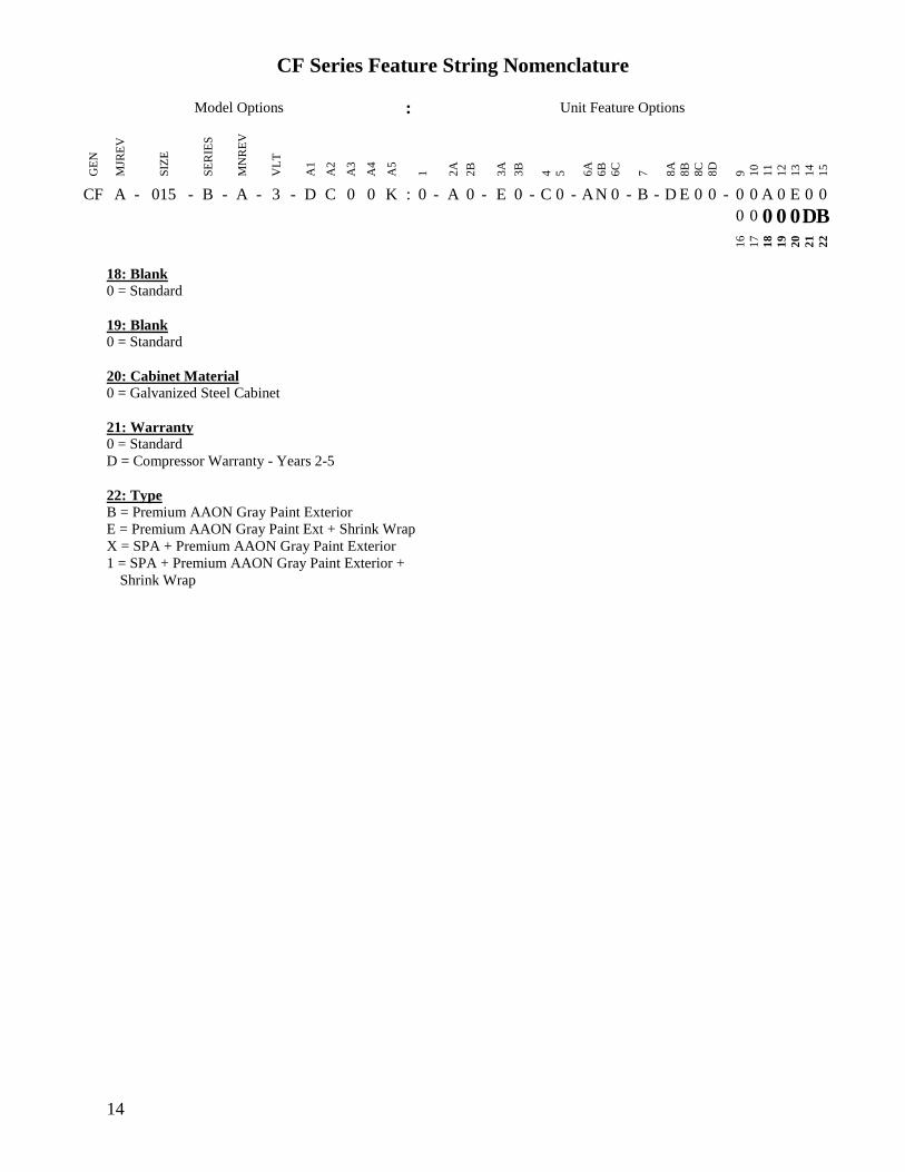
CF Series Feature String Nomenclature
Model Options Unit Feature Options G
EN
MJR
EV
SIZ
E
SE
RIE
S
MN
RE
V
VL
T
A1
A2
A3
A4
A5
1
2A
2B
3A
3B
4
5
6A
6B
6C
7
8A
8B
8C
8D
9
10
11
12
13
14
15
CF A - 015 - B - A - 3 - D C 0 0 K 0 - A 0 - E 0 - C 0 - A N 0 - B - D E 0 0 - 0 0 A 0 E 0 0
0 0 0 0 0 D B 1
6
17
18
19
20
21
22
14
18 Blank
0 = Standard
19 Blank
0 = Standard
20 Cabinet Material
0 = Galvanized Steel Cabinet
21 Warranty
0 = Standard
D = Compressor Warranty - Years 2-5
22 Type
B = Premium AAON Gray Paint Exterior
E = Premium AAON Gray Paint Ext + Shrink Wrap
X = SPA + Premium AAON Gray Paint Exterior
1 = SPA + Premium AAON Gray Paint Exterior +
Shrink Wrap
15
General Information
AAON CF Series air-cooled condensers and
condensing units have been designed for
outdoor use only They are factory
assembled wired charged and run-tested
Codes and Ordinances
CF Series units have been tested and
certified by ETL in accordance with UL
Safety Standard 1995CSA C222 No 236
System should be sized in accordance with
the American Society of Heating
Refrigeration and Air Conditioning
Engineers Handbook
Installation of CF Series units must conform
to the ICC standards of the International
Mechanical Code the International Building
Code and local building plumbing and
electrical codes All appliances must be
electrically grounded in accordance with
local codes or in the absence of local codes
the current National Electric Code
ANSINFPA 70 or the current Canadian
Electrical Code CSA C221
Receiving Unit
When received the unit should be checked
for damage that might have occurred in
transit If damage is found it should be noted
on the carrierrsquos freight bill A request for
inspection by carrierrsquos agent should be made
in writing at once Nameplate should be
checked to ensure the correct model sizes and
voltages have been received to match the job
requirements
If repairs must be made to damaged goods
then the factory should be notified before any
repair action is taken in order to protect the
warranty Certain equipment alteration
repair and manipulation of equipment
without the manufacturerrsquos consent may void
the product warranty Contact AAON
Technical Support for assistance with
handling damaged goods repairs and freight
claims (918) 382-6450
SHARP EDGES
Coils and sheet metal surfaces present sharp edges and care must be taken when working with equipment
WARNING
QUALIFIED INSTALLER
Improper installation adjustment alteration service or maintenance can cause property damage personal injury or loss of life Installation and service must be performed by a Factory Trained Service Technician
WARNING
Failure to observe the following instructions will result in premature failure of your system and possible voiding of the warranty
WARNING
16
Storage
If installation will not occur immediately
following delivery store equipment in a dry
protected area away from construction traffic
and in the proper orientation as marked on the
packaging with all internal packaging in
place Secure all loose-shipped items
Failure to observe the following instructions
will result in premature failure of your
system and possible voiding of the warranty
Never turn off the main power supply to the
unit except for complete shutdown When
power is cut off from the unit any
compressors using crankcase heaters cannot
prevent refrigerant migration This means the
compressor will cool down and liquid
refrigerant may accumulate in the
compressor The compressor is designed to
pump refrigerant gas and damage may occur
if liquid enters the compressor when power is
restored
Before unit operation the main power switch
must be turned on for at least twenty-four
hours for units with compressor crankcase
heaters This will give the crankcase heater
time to clear any liquid accumulation out of
the compressor before it is required to run
Always control the system from the control
panel never at the main power supply (except
for emergency or for complete shutdown of
the system)
CLEAN AIR ACT
The Clean Air Act of 1990 bans the intentional venting of refrigerant as of July 1 1992 Approved methods of recovery recycling or reclaiming must be followed
CAUTION
CRANKCASE HEATER OPERATION
Units are equipped with compressor crankcase heaters which should be energized at least 24 hours prior to cooling operation to clear any liquid refrigerant from the compressors
CAUTION
3-PHASE ROTATION
Rotation must be checked on all MOTORS AND COMPRESSORS of three phase units All motors to include and not be limited to pump motors and condenser fan motors should all be checked by a qualified service technician at startup and any wiring alteration should only be made at the unit power connection
CAUTION
17
The standard compressors must be on a
minimum of 5 minutes and off for a minimum
of 5 minutes The cycle rate must be no more
than 6 starts per hour
The variable capacity compressors must be
on a minimum of 3 minutes and off for a
minimum of 3 minutes The cycle rate must
be no more than 6 starts per hour
The compressor life will be seriously
shortened by reduced lubrication and the
pumping of excessive amounts of liquid oil
and liquid refrigerant
Wiring Diagrams
A complete set of unit specific wiring
diagram in point-to-point form is laminated
in plastic and located inside the control
compartment door
General Maintenance
When the initial startup is made and on a
periodic schedule during operation it is
necessary to perform routine service checks
on the performance of the condensing unit
This includes reading and recording suction
pressures and checking for normal sub-
cooling and superheat
COMPRESSOR ROTATION
Scroll compressors are directional and will be damaged by operation in the wrong direction Low pressure switches on compressors have been disconnected after factory testing Rotation should be checked by a qualified service technician at startup using suction and discharge pressure gauges and any wiring alteration should only be made at the unit power connection
COMPRESSOR CYCLING
5 MINUTE MINIMUM OFF TIME To prevent motor overheating compressors must cycle off for a minimum of 5 minutes
5 MINUTE MINIMUM ON TIME To maintain the proper oil level compressors must cycle on for a minimum of 5 minutes The cycle rate must not exceed 6 starts per hour
WARNING
CAUTION
18
Installation
Forklifting the Unit
CF Series condensing unit sizes 2-25 amp 30
tons can be lifted using a forklift 2-7 ton
units must have forks at least 48rdquo in length
9-25 amp 30 ton units must have forks 72rdquo in
length or the forks must have 72rdquo fork
extensions Standard units can be lifted from
all sides except the condenser coil side CF
Series condensing unit sizes 26 amp 31-70 tons
cannot be lifted using a forklift They can be
lifted as shown in Figure 3
Forks must be perpendicular to the unit and
they must be in far enough that the back of
the forks are no more than 6rdquo away from the
edge of the unit
Figure 1 - Forklifting a CF Series A Cabinet
Figure 2 - Forklifting a CF Series B and C
Cabinet
FORKLIFTING 2-7 TON UNITS
Forks or Fork Extensions must be at least 48rdquo in length
CAUTION
FORKLIFTING 9-25 amp 30 TON UNITS
Forks or Fork Extensions must be at least 72rdquo in length
CAUTION
19
Lifting the Unit
If cables or chains are used to hoist the unit
they must be the same length Minimum
cable length is 99rdquo for CF Series 9-70 ton
units CF Series 2-7 ton units do not include
factory installed lifting lugs and should be
lifted by forklift only Care should be taken
to prevent damage to the cabinet coils and
condenser fans
Before lifting unit be sure that all shipping
material has been removed from unit Secure
hooks and cables at all lifting points lugs
provided on the unit
Figure 3 ndash Lifting Details and Orientation of
a CF Series 9-70 ton Condensing Unit
Locating the Unit
The CF Series condenser and condensing unit
is designed for outdoor applications and
mounting at ground level or on a rooftop It
must be placed on a level and solid
foundation that has been prepared to support
its weight When installed at ground level a
one-piece concrete slab should be used with
footings that extend below the frost line Also
with ground level installation care must be
taken to protect the coil fins from damage due
to vandalism or other causes
The first clearance table below gives the
clearance values for proper unit operation
The second clearance table gives the
clearance necessary for removing the coil
without disassembling a large part of the
condensing unit For ease of removing the
condenser coil use the second table
clearances for the right hand side of the unit
Table 1 ndashClearances for Proper Operation
Location Unit Size
2-7 tons 9-70 tons
Front -
(Controls
Side)
Unobstructed 36rdquo
Left Side 6rdquo 30rdquo
Right Side 6rdquo 36rdquo
Top 3rdquo Unobstructed
Back 18rdquo 6rdquo
Table 2 ndash Clearances for Coil Pull
Unit Size Right Hand Side
2-7 tons 42rdquo
9-15 tons 42rdquo
16-25 amp 30 tons 54rdquo
26 amp 31-70 tons 66rdquo
Figure 4 - Orientation of Series 2-7 ton
Condensing Unit
20
The placement relative to the building air
intakes and other structures must be carefully
selected Airflow to and from the condenser
or condensing unit must not be restricted to
prevent a decrease in performance and
efficiency
The installation position for 9-70 ton units
must provide at least 30rdquo of left and right side
clearance for proper airflow to the condenser
coils When units are mounted adjacent to
each other the minimum right and left side
clearance required between the units is 60rdquo or
5 feet Similarly when 2-7 ton units are
mounted adjacent to each other the minimum
clearance required between the back side of
the units is 36rdquo or 3 feet
Units should not be installed in an enclosure
or pit that is deeper than the height of the unit
When recessed installation is necessary the
clearance to maintain proper airflow is at
least 5 feet (3 feet for 2-7tons)
CF Series condensers and condensing units
that have a vertical air discharge must have
no obstruction above the equipment Do not
place the unit under an overhang CF Series
condensers and condensing units that have a
horizontal discharge must have no
obstruction in front of the unit
For proper unit operation the immediate area
around condenser must remain free of debris
that may be drawn in and obstruct airflow in
the condensing section
Consideration must be given to obstruction
caused by snow accumulation when placing
the unit
Mounting Isolation
For roof mounted applications or anytime
vibration transmission is a factor vibration
isolators may be used
Access Doors
Access doors are provided to the compressor
and electrical compartment
Standard Evacuation Instructions
Proper system evacuation is critical to
remove moisture and non-condensables from
the system before charging the system with
refrigerant A newly installed AAON
condensing unit has already been evacuated
and charged with some refrigerant at the
factory When evacuating a new system
keep the condensing unit service valves
closed and evacuate the suction and liquid
lines and the air handling unit If the entire
system must be evacuated use the following
procedure to ensure the entire system is
pulled into a good vacuum
1 System evacuation should be
performed anytime a system is open to
atmospheric pressure The POE oils
used with R-410A are extremely
hydroscopic in nature and immediately
begin pulling in moisture once the
system is opened to the atmosphere
2 Before starting to evacuate the
system you MUST ensure that there are
no leaks by pressurizing the system with
PVC PIPING
PVC (Polyvinyl Chloride) and CPVC (Chlorinated Polyvinyl Chloride) are vulnerable to attack by certain chemicals Polyolester (POE) oils used with R-410A and other refrigerants even in trace amounts in a PVC or CPVC piping system will result in stress cracking of the piping and fittings and complete piping system failure
CAUTION
21
400 psig of dry nitrogen and verifying no
pressure loss after one hour
3 Four valve manifold gauge sets are
more effective than standard manifold
gauge sets due to the extra hose port in
combination with a 38rsquorsquo evacuation
port The larger diameter evacuation port
will expedite system evacuation
4 The manifold set should be connected
to the condensing unit with one hose on
the suction line service valve one hose
on the liquid line service valve and if an
extra Schrader valve is field installed on
the suction line connect a third hose (not
shown) The vacuum pump should be
connected to the manifold set using a
38rdquo vacuum rated hose Figure 5 shows
two circuits Both circuits must be
evacuated separately
Figure 5 ndash CU evacuation connections
5 An accurate micron gauge must be
used and checked by pulling a vacuum
on the gauge by itself and verify a rapid
drop to less than 100 microns within a
few minutes
6 The micron gauge should not be
attached to the system until the gauge
manifold is reading 28rsquorsquo of vacuum to
ensure the micron gauge does not see
pressure and is thus damaged MICRON
GAUGES WILL BE DAMAGED BY
PRESSURE
7 It is a good practice to replace the
vacuum pump oil after one hour of the
evacuation process The oil can be
broken down in the pump in the initial
first hour causing system evacuation to
take longer than it should
8 The minimum micron level required
by AAON is 350 microns for systems
using POE oils
9 The system should then be isolated
and the pump turned off to check for
vacuum rise due to leaks or moisture in
the system The micron gauge should
not rise above 500 microns after 30
minutes of wait time
Low Ambient amp Modulating Reheat
System Evacuation Instructions
Proper system evacuation is critical to
remove moisture and non-condensables from
the system before charging the system with
refrigerant Systems with low ambient
flooded condenser option require the
following procedure to ensure the entire
system is pulled into a good vacuum
1 System evacuation should be
performed anytime a system is open to
atmospheric pressure The POE oils
used with R-410A are extremely
hydroscopic in nature and immediately
begin pulling in moisture once the
system is opened to the atmosphere
2 Open the reheat valve to 50 when
evacuating
3 Before starting to evacuate the
system you MUST ensure that there are
no leaks by pressurizing the system with
22
400 psig of dry nitrogen and verifying no
pressure loss after one hour
4 Four valve manifold gauge sets are
more effective than standard manifold
gauge sets due to the extra hose port in
combination with a 38rsquorsquo evacuation
port The larger diameter evacuation port
will expedite system evacuation
5 The manifold set should be connected
to the condensing unit with one hose on
the suction line service valve one hose
on the liquid line service valve and a
third hose on the reheat line service
valve The vacuum pump should be
connected to the manifold set using a
38rdquo vacuum rated hose Figure 6 shows
two circuits The first circuit has a
reheat line the second circuit is just the
suction and liquid line Both circuits
must be evacuated separately
Figure 6 ndash CU evacuation connections
6 FAILURE to connect to the liquid
line service valve will result in the
receiver tank not being fully evacuated
and most likely lead to non-
condensables in the system
7 An accurate micron gauge must be
used and checked by pulling a vacuum
on the gauge by itself and verify a rapid
drop to less than 100 microns within a
few minutes
8 The micron gauge should not be
attached to the system until the gauge
manifold is reading 28rsquorsquo of vacuum to
ensure the micron gauge does not see
pressure and is thus damaged MICRON
GAUGES WILL BE DAMAGED BY
PRESSURE
9 It is a good practice to replace the
vacuum pump oil after one hour of the
evacuation process The oil can be
broken down in the pump in the initial
first hour causing system evacuation to
take longer than it should
10 The minimum micron level required
by AAON is 350 microns for systems
using POE oils
11 The system should then be isolated
and the pump turned off to check for
vacuum rise due to leaks or moisture in
the system The micron gauge should
not rise above 500 microns after 30
minutes of wait time
Adjusting Refrigerant Charge
All AAON CF Series condensers and
condensing units are shipped with a factory
holding charge The factory charge is
different depending on the unit size and
system (heat pump modulating hot gas
reheat LAC) The factory charge per circuit
is shown on the unit nameplate Adjusting the
charge of the system will be required during
installation
23
Adjusting the charge of a system in the field
must be based on determination of liquid sub-
cooling and evaporator superheat On a
system with a thermostatic expansion valve
liquid sub-cooling is more representative of
the charge than evaporator superheat but both
measurements must be taken
Before Charging
Refer to the Unit Nameplate to determine
which refrigerant must be used to charge the
system
Unit being charged must be at or near full
load conditions before adjusting the charge
Units equipped with hot gas bypass must
have the hot gas bypass valve closed to get
the proper charge
Units equipped with hot gas reheat must be
charged with the hot gas valve closed while
the unit is in cooling mode After charging
unit should be operated in reheat
(dehumidification) mode to check for correct
operation
Units equipped with heat pump options
should be charged in cooling mode to get the
proper charge After charging unit should be
operated in heating mode to check for correct
charge Charge may need to be adjusted for
heating mode If adjustments are made in the
heating mode cooling mode must be rerun to
verify proper operation
After adding or removing charge the system
must be allowed to stabilize typically 10-15
minutes before making any other
adjustments
The type of unit and options determine the
ranges for liquid sub-cooling and evaporator
superheat Refer to Table 3 when determining
the proper sub-cooling
For units equipped with low ambient (0degF)
option see the special charging instructions at
the end of this section
Checking Liquid Sub-cooling
Measure the temperature of the liquid line as
it leaves the condenser coil
Read the gauge pressure at the liquid line
close to the point where the temperature was
taken You must use liquid line pressure as it
will vary from discharge pressure due to
condenser coil pressure drop
Convert the pressure obtained to a saturated
temperature using the appropriate refrigerant
temperature-pressure chart
COMPRESSOR LUBRICANT
Polyolester (POE) and Polyvinylether (PVE) oils are two types of lubricants used in hydrofluorocarbon (HFC) refrigeration systems Refer to the compressor label for the proper compressor lubricant type
CAUTION
CLEAN AIR ACT
The Clean Air Act of 1990 bans the intentional venting of refrigerant (CFCrsquos and HCFCrsquos) as of July 1 1992 Approved methods of recovery recycling or reclaiming must be followed Fines andor incarceration may be levied for non-compliance
CAUTION
24
Subtract the measured liquid line temperature
from the saturated temperature to determine
the liquid sub-cooling
Compare calculated sub-cooling to Table 3
for the appropriate unit type and options
Table 3 - Acceptable Refrigeration Circuit
Values
Cooling
Mode
Liquid Sub-
Cooling
Values
Cooling Only Unit4 8-15degF
Cooling Only Unit with Hot
Gas Reheat14 5-15degF
Heat PumpUnit24 2-4degF
Heat Pump Unit with Hot
Gas Reheat34 2-6degF
Cooling Only Unit with
LAC4 8-15degF
Cooling Only Unit with Hot
Gas Reheat amp LAC4 8-15degF
Notes 1 Must be charged with the hot gas valve
closed After charging unit should be
operated in reheat (dehumidification) mode
to check for correct operation
2 The sub-cooling value in this table is for the
unit running in cooling mode of operation
After charging unit should be operated in
heating mode to check for correct operation
3 The sub-cooling value in this table is for the
unit running in cooling mode of operation
and the hot gas valve closed After charging
unit should be operated in reheat
(dehumidification) mode to check for correct
operation and then in heating mode to check
for correct operation
4 Sub-cooling must be increased by 1degF per 10
feet of vertical liquid line rise for R-410A
(AHU above CU) For example a cooling
only unit with hot gas reheat and a vertical
liquid drop can charge to a sub-cooling value
of 5-15degF but a cooling only unit with hot
gas reheat and a vertical liquid rise of 30 ft
must charge to a sub-cooling value of at least
8-15degF DO NOT OVERCHARGE
Refrigerant overcharging leads to excess
refrigerant in the condenser coils resulting in
elevated compressor discharge pressure
Checking Evaporator Superheat
Measure the temperature of the suction line
close to the compressor
Read gauge pressure at the suction line close
to the compressor
Convert the pressure obtained to a saturated
temperature using the appropriate refrigerant
temperature-pressure chart
Subtract the saturated temperature from the
measured suction line temperature to
determine the evaporator superheat
For refrigeration systems with tandem
compressors it is critical that the suction
superheat setpoint on the TXV is set with one
compressor running The suction superheat
should be 10-13degF with one compressor
running The suction superheat will increase
with both compressors in a tandem running
Inadequate suction superheat can allow liquid
refrigerant to return to the compressors which
will wash the oil out of the compressor Lack
of oil lubrication will destroy a compressor
Liquid sub-cooling should be measured with
both compressors in a refrigeration system
running
Compare calculated superheat to the
acceptable cooling mode superheat values of
8-15degF for all system types Superheat will
increase with long suction line runs
25
Adjusting Sub-cooling and Superheat
Temperatures
The system is overcharged if the sub-cooling
temperature is too high compared to Table 3
and the evaporator is fully loaded (low loads
on the evaporator result in increased sub-
cooling) and the evaporator superheat is
within the temperature range of 8-15degF (high
superheat results in increased sub-cooling)
Correct an overcharged system by reducing
the amount of refrigerant in the system to
lower the sub-cooling
The system is undercharged if the superheat
is too high and the sub-cooling is too low
Correct an undercharged system by adding
refrigerant to the system to reduce superheat
and raise sub-cooling
If the sub-cooling is correct and the superheat
is too high the TXV may need adjustment to
correct the superheat
DO NOT OVERCHARGE Refrigerant overcharging leads to excess refrigerant in the condenser coils resulting in elevated compressor discharge pressure
CAUTION
EXPANSION VALVE ADJUSTMENT
Thermal expansion valves must be adjusted to approximately 8-15degF of suction superheat Failure to have sufficient superheat will damage the compressor and void the warranty
CAUTION
26
Special Low Ambient Option Charging
Instructions
For units equipped with low ambient
refrigerant flood back option being charged
in the summer when the ambient
temperature is warm
If the ambient is above 70degF charge to
approximately 1-2degF of sub-cooling
measured at the inlet to the expansion valve
Once enough charge has been added to get
the evaporator superheat and sub-cooling
values to the correct setting more charge
must be added Use Table 4 to find the
additional charge amount required for the
system when running in cold ambient
conditions
Table 4 ndash Charge to Flood Condenser Coil
for Ambient Above 70degF
CF Size of
circuits
Per Circuit
Charge (lbs)
CF 2 3 1 49
CF 4 5 6 7 1 92
CF 9 11 2 91
CF 13 15 2 121
CF 16 18 2 131
CF 20 25 30 2 175
CF 26 31 40 2 180
4 91
CF 50 60 70 2 438
4 221
For units equipped with low ambient
refrigerant flood back option being charged
in the winter when the ambient
temperature is cold
1 If the ambient is below 70degF charge
to approximately 1-2degF of sub-cooling
measured at the inlet to the expansion
valve Once enough charge has been
added to get the evaporator superheat
and sub-cooling values to the correct
setting more charge may need to be
added If the ambient temperature is 0degF
no more charge is required Ambient
temperatures above 0degF will require a
percentage of the per circuit charge
values from Table 4 Using your
ambient temperature find the
percentage value from Table 5 and
multiply the Per Circuit Charge value
from Table 4 and the value to
determine the additional charge amount
Table 5 ndash Charge to Flood Condenser
Coil for Ambient Below 70degF
Condenser
Ambient
Temperature ˚F
Percentage
Per Circuit
Charge from
Table 4
60 60
50 37
40 24
30 15
20 8
0 0
2 The unit should be checked for proper
operation once the ambient temperature
is above 80degF
Example A CF size 31 with tandem
compressors where the ambient
temperature is 40degF
From Table 4 ndash 18 lbs refrigerant charge
per circuit (tandem compressors would
have 2 circuits in this size of CF)
From Table 5 ndash 24 of Table 4 charge
Additional charge needed for a unit with
low ambient flooded condenser controls
= 18 lbs 024 = 432 lbs additional
refrigerant charge per circuit
27
Low Ambient Operation
During low ambient temperatures the vapor
refrigerant will migrate to the cold part of the
system and condense into liquid All CF
Series compressors are provided with factory
installed crankcase heaters to help prevent
liquid refrigerant from slugging the
compressors during startup in low ambient
conditions The condenser or condensing unit
must have continuous power 24 hours prior
to startup This ensures the compressor will
receive sufficient refrigerant vapor at startup
Standard units can operate down to 55degF
ambient temperature
AAON condenser fan head pressure control
units can operate down to 35degF ambient
temperature Three different condenser fan
head pressure control options available are
adjustable fan cycling ECM condenser fan
or VFD controlled condenser fans See
detailed information following
The AAON low ambient (condenser flood-
back) system is used to operate a refrigerant
system down to 0degF outside air temperature
See detailed information following
Fan Cycling Low Ambient
Adjustable fan cycling is a low ambient head
pressure control option that cycles the
condenser fans to maintain refrigerant circuit
head pressures at acceptable levels during
cooling operation The head pressure set
point (100-470 psi) and pressure differential
(35-200 psi) can be field adjusted using a
flathead screwdriver For example if the
head pressure is set to 300psi and the
differential is set to 100psi then fans will cut
in at 300psi and cut out at 200psi Fan
cycling and variable speed condenser fan
head pressure control options allow
mechanical cooling with ambient
temperatures down to 35degF
Figure 7 - Adjustable Fan Cycling Switch
Variable Speed Low Ambient
Variable speed condenser fan head pressure
control is a low ambient head pressure
control option that sends a variable signal in
relation to the refrigerant circuit head
pressure of the system to an electronically
commutated motor (ECM) or VFD The
motor either speeds up or slows down air
flow accordingly in order to maintain
constant head pressure Fan cycling and
variable speed condenser fan head pressure
control options allow mechanical cooling
with ambient temperatures down to 35degF
Flooded Condenser Low Ambient
Flooded condenser low ambient control
maintains normal head pressure during
periods of low ambient When the ambient
temperature drops the condensing
temperature and therefore pressure drops
Without ambient control the system would
shut down on low discharge pressure The
flooded condenser method of low ambient
control fills the condenser coil with liquid
refrigerant decreasing the heat transfer
capacity of the coil which allows the coil to
operate at an acceptable discharge pressure
28
The condenser coil will not be flooded during
summer ambient temperatures so a receiver
is included to store the additional liquid
refrigerant required to flood the condenser
coil in low ambient The receiver is factory-
sized to contain all of the flooded volume
Without a receiver there would be high head
pressures during higher ambient conditions
The low ambient system maintains normal
head pressure during periods of low ambient
by restricting liquid flow from the condenser
to the receiver and at the same time
bypassing hot gas around the condenser to the
inlet of the receiver This reduces liquid
refrigerant flow from the condenser reducing
its effective surface area which in turn
increases the condensing pressure At the
same time the bypassed hot gas raises liquid
pressure in the receiver allowing the system
to operate properly CF Series condensers
and condensing units use an LAC valve for
low ambient operation
LAC Valve
The Low Ambient Control (LAC) valve is a
non-adjustable three way valve that
modulates to maintain receiver pressure As
the receiver pressure drops below the valve
setting (295 psig for R-410A) the valve
modulates to bypass discharge gas around the
condenser The discharge gas warms the
liquid in the receiver and raises the pressure
to the valve setting The following schematic
shows an example system using the LAC
valve
Figure 8 ndash LAC Piping Example
29
Refrigerant Piping
(See back of the manual for refrigerant piping
diagrams)
General
Piping from the condensing unit to the air
handler is the responsibility of the installing
contractor
Use only clean type ldquoACRrdquo copper tubing
that has been joined with high temperature
brazing alloy
The pipe or line sizes must be selected to
meet the actual installation conditions and
NOT simply based on the connection sizes at
the condensing unit or air handler
All CF Series condensing units are provided
with in-line shutoff valves on both the liquid
and suction lines These should remain closed
until the system is ready for start-up after
installation
Piping should conform to generally accepted
practices and codes
Care must be taken not to cross the circuits
on multiple circuit systems
Upon completion of piping connection the
interconnecting piping and air handler MUST
BE evacuated to 500 microns or less leak
checked and charged with refrigerant
Determining Refrigerant Line Size
The piping between the condenser and low
side must ensure
1 Minimum pressure drop and
2 Continuous oil return and
3 Prevention of liquid refrigerant slugging
or carryover
Minimizing the refrigerant line size is
favorable from an economic perspective
reducing installation costs and reducing the
potential for leakage However as pipe
diameters decrease pressure drop increases
Excessive suction line pressure drop causes
loss of compressor capacity and increased
power usage resulting in reduced system
efficiency Excessive pressure drops in the
liquid line can cause the liquid refrigerant to
flash resulting in faulty TXV operation and
improper system performance In order to
operate efficiently and cost effectively while
avoiding malfunction refrigeration systems
must be designed to minimize both cost and
pressure loss
REFRIGERANT PIPING
Line sizes must be selected to meet actual installation conditions not simply based on the connection sizes at the condensing unit or air handling unit
CAUTION
REFRIGERANT PIPING
This section is for information only and is not intended to provide all details required by the designer or installer of the refrigerant piping between the condenser or condensing unit and the air handling unit AAON Inc is not responsible for interconnecting refrigerant piping Consult ASHRAE Handbook ndash Refrigeration and ASME Standards
CAUTION
30
Equivalent Line Length
All line lengths discussed in this manual
unless specifically stated otherwise are
Equivalent Line Lengths The frictional
pressure drop through valves fittings and
accessories is determined by establishing the
equivalent length of straight pipe of the same
diameter Always use equivalent line
lengths when calculating pressure drop
Special piping provisions must be taken
when lines are up vertical risers or in
excessively long line runs AAON does not
recommend running underground
refrigerant lines
Liquid Line
When sizing the liquid line it is important to
minimize the refrigerant charge to reduce
installation costs and improve system
reliability This can be achieved by
minimizing the liquid line diameter
However reducing the pipe diameter will
increase the velocity of the liquid refrigerant
which increases the frictional pressure drop
in the liquid line and causes other
undesirable effects such as noise
Maintaining the pressure in the liquid line is
critical to ensuring sufficient saturation
temperature avoiding flashing upstream of
the TXV and maintaining system efficiency
Pressure losses through the liquid line due to
frictional contact installed accessories and
vertical risers are inevitable Maintaining
adequate sub-cooling at the condenser to
overcome these losses is the only method to
ensure that liquid refrigerant reaches the
TXV
Liquid refrigerant traveling upwards in a riser
loses head pressure If the evaporator is
below the condenser with the liquid line
flowing down the gravitational force will
increase the pressure of the liquid refrigerant
This will allow the refrigerant to withstand
greater frictional losses without the
occurrence of flashing prior to the TXV
A moisture-indicating sight glass may be
field installed in the liquid line to indicate the
occurrence of premature flashing or moisture
in the line The sight glass should not be used
to determine if the system is properly
charged Use temperature and pressure
measurements to determine liquid sub-
cooling not the sight glass
Liquid Line Routing
Care should be taken with vertical risers
When the system is shut down gravity will
pull liquid down the vertical column and
back to the condenser when it is below the
evaporator This could potentially result in
compressor flooding A check valve can be
installed in the liquid line where the liquid
column rises above the condenser to prevent
this The liquid line is typically pitched along
with the suction line or hot gas line to
minimize the complexity of the
configuration
Liquid Line Insulation
In cooling only systems when the liquid line
is routed through regions where temperature
losses are expected no insulation is required
as this may provide additional sub-cooling to
the refrigerant When routing the liquid line
through high temperature areas insulation of
the line is appropriate to avoid loss of sub-
cooling through heat gain
In heat pump systems when the liquid line is
routed through regions where temperature
losses are expected (all lines exposed to
outside air conditions) insulate with a
minimum 1 inch thick Armaflex insulation
as this will prevent capacity loss during
heating mode of operation
31
Liquid Line Guidelines
In order to ensure liquid at the TXV the sum
of frictional losses and pressure loss due to
vertical rise must not exceed available sub-
cooling A commonly used guideline to
consider is a system design with pressure
losses due to friction through the line not to
exceed a corresponding 1-2degF change in
saturation temperature An additional
recommendation is that the sum of frictional
losses (including valve losses filter drier
losses other accessories and line losses) and
pressure loss due to vertical rise should not
exceed 8degF if the available sub-cooling is
10degF
If the velocity of refrigerant in the liquid line
is too great it could cause excessive noise or
piping erosion The recommended maximum
velocities for liquid lines are 100 fpm from
the condenser to a receiver to discourage
fluid backup and 500 fpm from receiver tank
to the evaporator (300 fpm if the line includes
an electric valve to minimize valve induced
liquid hammer)
Liquid Line Accessories
Liquid line shut off valves and filter driers are
factory provided The total length equivalent
of pressure losses through valves elbows and
fittings must be considered when adding
additional components in the field It is a
good practice to utilize the fewest elbows that
will allow the mating units to be successfully
joined
A liquid line receiver is factory installed on
units with modulating hot gas reheat units
with low ambient control flooded condenser
and units with heat pump
Suction Line
The suction line is more critical than the
liquid line from a design and construction
standpoint More care must be taken to
ensure that adequate velocity is achieved to
return oil to the compressor at minimum
loading conditions However reducing the
piping diameter to increase the velocity at
minimal load can result in excessive pressure
losses capacity reduction and noise at full
load
Suction Line Routing
For cooling only systems pitch the suction
line in the direction of flow (about 1 inch per
20 feet of length) to maintain oil flow
towards the compressor and keep it from
flooding back into the evaporator
For heat pump systems do not pitch lines
since they will be flowing in one direction in
cooling mode and the opposite direction in
heating mode
Crankcase heaters are provided to keep any
condensed refrigerant that collects in the
compressor from causing damage or wear
Make sure to provide support to maintain
suction line positioning and insulate
completely between the evaporator and
condensing unit
It is important to consider part load operation
when sizing suction lines At minimum
capacity refrigerant velocity may not be
adequate to return oil up the vertical riser
Decreasing the diameter of the vertical riser
will increase the velocity but also the
frictional loss
For difficult line routing applications a
double suction riser can be applied to the
situation of part load operation with a suction
riser A double suction riser is designed to
return oil at minimum load while not
incurring excessive frictional losses at full
load A double suction riser consists of a
small diameter riser in parallel with a larger
diameter riser and a trap at the base of the
large riser At minimum capacity refrigerant
velocity is not sufficient to carry oil up both
32
risers and it collects in the trap effectively
closing off the larger diameter riser and
diverting refrigerant up the small riser where
velocity of the refrigerant is sufficient to
maintain oil flow At full load the mass flow
clears the trap of oil and refrigerant is carried
through both risers The smaller diameter
pipe should be sized to return oil at minimum
load while the larger diameter pipe should be
sized so that flow through both pipes
provides acceptable pressure drop at full
load
Figure 9 - Double Suction Riser
Construction
A double riser can also be used for heat pump
operation The specific volume (ft3lb) of
refrigerant at the discharge temperature and
pressure (heating mode line conditions) is
significantly lower than the specific volume
at the suction temperature and pressure
(cooling mode line conditions) To
compound the issue the capacity in heating
mode is lower than the capacity in cooling
mode The discharge velocity in the riser
during heating mode is much lower than the
suction velocity during cooling mode Often
a double riser is necessary to get acceptable
velocities for the discharge mode and
acceptable velocities for the suction mode In
the example diagrams (See Figure 10 amp
Figure 11) the cooling mode will use both
lines and the heating mode will use only one
Suction Line Traps
Include a trap immediately after the
evaporator coil outlet to protect the TXV bulb
from liquid refrigerant
Include traps every 20 feet in vertical suction
riser sections for cooling only systems and
every 12 feet for heat pump systems
Suction Line Insulation
The entire suction line should be insulated
with a minimum 1 inch thick Armaflex
insulation This prevents condensation from
forming on the line and reduces any potential
loss in capacity associated with heat gain
placing additional load on the system This
line should still be insulated in heat pump
systems even though it acts as both a
discharge and suction line
Suction Line Guidelines
For proper performance suction line
velocities less than a 4000 fpm maximum are
recommended The minimum velocity
required to return oil is dependent on the pipe
diameter however a general guideline of
1000 fpm minimum may be applied
When suction flow is up variable capacity
compressors require a minimum velocity of
1500 fpm at full load
Tandem compressors must be considered for
full load operation (both compressors
operating) and at partial load (only one
compressor operating) When suction flow is
up and the tandem has a variable capacity
compressor the velocity for only one
compressor in operation must be greater than
1500 fpm For onoff compressors the
velocity must be greater than the minimum
velocity required to return oil
Heat pump vapor lines must be checked for
suction flow (cooling mode operation) and
discharge flow (heating mode operation)
33
The same line must be used for both modes
of operation
In a fashion similar to the liquid line a
common guideline to consider is a system
design with pressure losses due to friction
through the line not to exceed a
corresponding 1-2degF change in saturation
temperature
For split system piping with long horizontal
runs and short vertical risers a smaller pipe
size can be used to provide sufficient velocity
to return oil in vertical risers at part loads and
a larger size pipe can be used on the
horizontal runs and vertical drop sections
This helps with oil return yet keeps the
pressure drop to a minimum
Suction Line Accessories
If the job requirements specify suction
accumulators they must be separately
purchased and field installed Heat pump
units will include a factory installed suction
accumulator
Discharge Line
The discharge line is similar to the suction
line from a design and construction
standpoint Care must be taken to ensure that
adequate velocity is achieved to return oil to
the compressor at minimum loading
conditions However reducing the piping
diameter to increase the velocity at minimal
load can result in excessive pressure losses
capacity reduction and noise at full load
Pressure loss in the discharge line has less of
an impact on capacity than pressure loss in
the suction line Pressure loss in the
discharge line causes the compressors to
work harder and thus use more power
Discharge Line Routing
For cooling only remote condenser systems
pitch the discharge line in the direction of
flow (about 1 inch per 20 feet of length) to
maintain oil flow towards the compressor
In a heat pump system the field installed
suction line is also used as a discharge line in
the heating mode of operation so the line
must be sized to meet both the suction line
conditions in cooling mode and the discharge
line conditions in heating mode
Because it is used in both directions for a heat
pump unit the line should be installed level
not pitched to facilitate oil return in both
modes of operation
It is important to consider part load operation
when sizing discharge lines At minimum
capacity refrigerant velocity may not be
adequate to return oil up the vertical riser
Decreasing the diameter of the vertical riser
will increase the velocity but also the
frictional loss
For difficult line routing applications a
double discharge riser can be applied to the
situation of part load operation with a
discharge riser A double discharge riser is
designed to return oil at minimum load while
not incurring excessive frictional losses at
full load A double discharge riser consists of
a small diameter riser in parallel with a larger
diameter riser and a trap at the base of the
large riser At minimum capacity refrigerant
velocity is not sufficient to carry oil up both
risers and it collects in the trap effectively
closing off the larger diameter riser and
diverting refrigerant up the small riser where
SUCTION RISER TRAPS
Circuits require suction riser traps every 20 feet (every 12 feet for heat pumps)
CAUTION
34
velocity of the refrigerant is sufficient to
maintain oil flow At full load the mass flow
clears the trap of oil and refrigerant is carried
through both risers The smaller diameter
pipe should be sized to return oil at minimum
load while the larger diameter pipe should be
sized so that flow through both pipes
provides acceptable pressure drop at full
load (See the Double Suction Riser
Construction Figure 9)
A double riser can also be used for heat pump
operation The specific volume (ft3lb) of
refrigerant at the discharge temperature and
pressure (heating mode line conditions) is
significantly lower than the specific volume
at the suction temperature and pressure
(cooling mode line conditions) To
compound the issue the capacity in heating
mode is lower than the capacity in cooling
mode The discharge velocity in the riser
during heating mode is much lower than the
suction velocity during cooling mode Often
a double riser is necessary to get acceptable
velocities for the discharge mode and
acceptable velocities for the suction mode In
the example diagrams the cooling mode will
use both lines and the heating mode will use
only one See the following schematics that
illustrate how the double discharge riser can
work for heat pump applications
Figure 10 ndash Heat Pump Piping Schematic of
Cooling Mode in Double Riser
Figure 11 ndash Heat Pump Piping Schematic of
Heating Mode in Double Riser
35
Discharge Line Traps
Include traps every 12 feet in vertical
discharge riser sections
Discharge Line Insulation
Although a typical discharge line does not
need to be insulated the suction line does
Since the same line is used for both the line
must be insulated as described in the Suction
Line Insulation section
Discharge Line Guidelines
For proper performance discharge line
velocities less than a 3500 fpm maximum are
recommended The minimum velocity
required to return oil is dependent on the pipe
diameter however a general guideline of
900 fpm minimum may be applied
When discharge flow is up variable capacity
compressors require a minimum velocity of
900 fpm at full load
Tandem compressors must be considered for
full load operation (both compressors
operating) and at partial load (only one
compressor operating) When discharge flow
is up and the tandem has a variable capacity
compressor the velocity for only one
compressor in operation must be greater than
900 fpm For onoff compressors the
velocity must be greater than the minimum
velocity required to return oil
Heat pump vapor lines must be checked for
suction flow (cooling mode operation) and
discharge flow (heating mode operation)
The same line must be used for both modes
of operation
In a fashion similar to the suction line a
common guideline to consider is a system
design with pressure losses due to friction
through the line not to exceed a
corresponding 1-2degF change in saturation
temperature
For split system piping with long horizontal
runs and short vertical risers a smaller pipe
size can be used to provide sufficient velocity
to return oil in vertical risers at part loads and
a larger size pipe can be used on the
horizontal runs and vertical drop sections
This helps with oil return yet keeps the
pressure drop to a minimum
Hot Gas Bypass Line
Hot Gas Bypass is available for use with DX
systems that may experience low suction
pressure during the operating cycle This may
be due to varying load conditions associated
with VAV applications or units supplying a
large percentage of outside air The system is
designed to divert refrigerant from the
compressor discharge to the low pressure
side of the system in order to keep the
evaporator from freezing and to maintain
adequate refrigerant velocity for oil return at
minimum load
Hot discharge gas is redirected to the
evaporator inlet via an auxiliary side
connector (ASC) to false load the evaporator
when reduced suction pressure is sensed
Field piping between the condensing unit
and the evaporator is required
Hot Gas Bypass Piping Considerations
Pitch the hot gas bypass (HGB) line
downward in the direction of refrigerant
flow toward the evaporator
DISCHARGE RISER TRAPS
Circuits require discharge riser traps every 12 feet
CAUTION
36
When installing vertical hot gas bypass lines
an oil drip line must be provided at the lowest
point in the system The oil drip line must be
vertical its diameter should be the same as
the diameter of the riser and it should be
1 foot long Install a sight glass in the oil drip
line for observation Run an oil return line
using 18 inch capillary tube 10 feet in
length from the hot gas bypass line oil drip
line to the suction line Connect the oil return
line below the sight glass and 1 inch above
the bottom of the oil drip line
Figure 12 ndash Oil Return Line
HGB valves are adjustable Factory HGB
valve settings will be sufficient for most
applications but may require slight
adjustments for some applications including
some make up air applications
Insulate the entire length of the HGB line
with a minimum 1 inch thick Armaflex
insulation
Hot Gas Bypass Line Guidelines
Choose a small size line to ensure oil return
and minimize refrigerant charge
Maintain velocities below a maximum of
3500 fpm A general minimum velocity
guideline to use is approximately 2000 fpm
Hot Gas Reheat
The AAON modulating hot gas reheat system
diverts hot discharge gas from the condenser
to the air handling unit through the hot gas
line Field piping between the condensing
unit and the air handler is required
The line delivers the hot discharge gas to the
reheat coil andor the hot gas bypass valve so
it is sized as a discharge line
Discharge lines should be sized to ensure
adequate velocity of refrigerant to ensure oil
return avoid excessive noise associated with
velocities that are too high and to minimize
efficiency losses associated with friction
Pitch the hot gas line in the direction of flow
for oil return
When installing vertical hot gas reheat lines
an oil drip line must be provided at the lowest
point in the system The oil drip line must be
vertical its diameter should be the same as
the diameter of the riser and it should be
1 foot long Run an oil return line using 18
inch capillary tube 10 feet in length from the
hot gas reheat line oil drip line to the suction
line Connect the oil return line below the
sight glass and 1 inch above the bottom of the
oil drip line (See Oil Return Line Figure 12)
Insulate the entire length of the hot gas line
with a minimum 1 inch thick Armaflex
insulation
Hot Gas Reheat Guidelines
Maintain velocities below a maximum of
3500 fpm A general minimum velocity
guideline is 2000 fpm
37
Electrical
The single point electrical power connections
are made in the electrical control compartment
Verify the unit nameplate voltage agrees with
the power supply Connect power and control
field wiring as shown on the unit specific
wiring diagram provided with the unit
Table 6 - Nameplate Voltage Markings
Voltage Feature
Nameplate
Voltage
Marking
MinMax
VAC
1 230V1Φ60Hz 230 197252
2 230V3Φ60Hz 230 197252
3 460V3Φ60Hz 460 456504
4 575V3Φ60Hz 575 570630
8 208V3Φ60Hz 208 197228
9 208V1Φ60Hz 208 197228
NOTE Units are factory wired for 208V
230V 460V or 575V In some units the 208V
and 230V options may also be provided in
single or three phase configurations The
transformer configuration must be checked by
a qualified technician prior to startup
Size supply conductors based on the unit MCA
rating Supply conductors must be rated a
minimum of 167degF (75degC)
Route power and control wiring separately
through the utility entry Do not run power and
signal wires in the same conduit
Protect the branch circuit in accordance with
code requirements The unit must be
electrically grounded in accordance with local
codes or in the absence of local codes the
current National Electric Code ANSINFPA
70 or the current Canadian Electrical Code
CSA C221
Power wiring is to the unit terminal block or
main disconnect All wiring beyond this point
has been done by the manufacturer and cannot
be modified without affecting the units
agencysafety certification
Three phase voltage imbalance will cause
motor overheating and premature failure The
maximum allowable imbalance is 5
Voltage imbalance is defined as 100 times the
maximum deviation from the average voltage
divided by the average voltage
Example
(218V+237V+235V)3 = 230V then
100(230V-218V)230V = 52 which
exceeds the allowable imbalance
Check voltage imbalance at the unit disconnect
switch and at the compressor terminal
Contact your local power company for line
voltage corrections
3-PHASE ROTATION
Rotation must be checked on all MOTORS AND COMPRESSORS of three phase units Condenser fan motors should be checked by a qualified service technician at startup and any wiring alteration should only be made at the unit power connection Variable frequency drives are programmed to automatically rotate the fan in the correct rotation Do not rely on fans with variable frequency drives for compressor rotation
CAUTION
38
NOTE Startup technician must check for
proper motor rotation and check fan motor
amperage listed on the motor nameplate is not
exceeded Motor overload protection may be a
function of the variable frequency drive and
must not be bypassed
Wire control signals to the unitrsquos low voltage
terminal block located in the controls
compartment
If any factory installed wiring must be
replaced use a minimum 221degF (105degC) type
AWM insulated conductors
ELECTRIC SHOCK
Electric shock hazard Before attempting to perform any installation service or maintenance shut off all electrical power to the unit at the disconnect switches Unit may have multiple power supplies Failure to disconnect power could result in dangerous operation serious injury death or property damage
WARNING
SEALING ELECTRICAL ENTRIES
Installing Contractor is responsible for proper sealing of the electrical entries into the unit Failure to seal the entries may result in damage to the unit and property
CAUTION
39
Startup (See back of the manual for startup form)
Before startup of the condenser or condensing
unit make sure that the following items have
been checked
1 Verify that electrical power is available to
the unit
2 Verify that any remote stopstart device
connected to the unit controller is
requesting the unit to start
Cycle through all the compressors to confirm
that all are operating within tolerance
While performing the check use the startup
form to record observations of amps and
refrigerant pressures
When all is running properly place the
controller in the Run mode and observe the
system until it reaches a steady state of
operation
Compressor Operation
The compressors must be off for a minimum of
5 minutes and on for a minimum of 5 minutes
Short cycling of the compressors can cause
undue stress and wear
3-PHASE ROTATION
Rotation must be checked on all MOTORS AND COMPRESSORS of three phase units Condenser fan motors should all be checked by a qualified service technician at startup and any wiring alteration should only be made at the unit power connection Variable frequency drives are programmed to automatically rotate the fan in the correct rotation Do not rely on fans with variable frequency drives for compressor rotation
CAUTION
ELECTRIC SHOCK
Electric shock hazard Shut off all electrical power to the unit to avoid shock hazard or injury from rotating parts
WARNING
QUALIFIED INSTALLER
Improper installation adjustment alteration service or maintenance can cause property damage personal injury or loss of life Startup and service must be performed by a Factory Trained Service Technician
WARNING
Before completing installation a complete operating cycle should be observed to verify that all components are functioning properly
CAUTION
40
Variable Capacity Compressor Controller
Units with variable capacity scroll
compressors may include a variable capacity
compressor controller The following is an
explanation of the terminals and
troubleshooting of the alert flash codes on the
controller For more information on the
compressor controller see Emerson Climate
Bulletin AE8-1328
Figure 13 - Variable Capacity Compressor
Controller
Note When using field controls any variable
capacity compressors should run at 100 for 1
minute when starting
Low Voltage Terminals
24COM Module Common
24VAC Module Power
C1 Demand Input -
C2 Demand Input +
P1 Pressure Common
P2 Pressure Input
P3 Pressure Power 5VDC
P4 Pressure Shield
P5 Pressure Output -
P6 Pressure Output +
T1 amp T2 Discharge Temperature Sensor
High Voltage Terminals
A1 amp A2 Alarm Relay Out
M1 amp M2 Contactor
L1 Control Voltage N
L2 Control Voltage L
U1 amp U2 Variable Capacity Unloader Solenoid
V1 amp V2 Vapor Injection Solenoid
The compressor controller modulates the
compressor unloader solenoid in an onoff
pattern according the capacity demand signal
of the system The following table shows the
linear relationship between the demand signal
and compressor capacity modulation The
compressor controller also protects the
compressor against high discharge
temperature Refer to Table 8 for the
relationship between thermistor temperature
readings and resistance values
COMPRESSOR CONTROLLER
To avoid damaging the compressor controller DO NOT connect wires to terminals C3 C4 T3 T4 T5 or T6
WARNING
COMPRESSOR CYCLING
5 MINUTE MINIMUM OFF TIME To prevent motor overheating compressors must cycle off for a minimum of 5 minutes
5 MINUTE MINIMUM ON TIME To maintain the proper oil level compressors must cycle on for a minimum of 5 minutes The cycle rate must not exceed 6 starts per hour
WARNING
41
Table 7 - Demand Signal vs Compressor Capacity Modulation
Figure 14 - Compressor Controller Flash Code Details
Demand
Signal (VDC) Loaded Unloaded Time Loaded
Time
Unloaded
Compressor
Capacity
100 Off Off Off Off 0
144 10 90 15 sec 135 sec 10
300 50 50 75 sec 75 sec 50
420 80 20 12 sec 3 sec 80
500 100 0 15 sec 0 sec 100
42
Table 8 - Thermistor Temperature vs Resistance Values
degC degF kΩ degC degF kΩ
-40 -40 288960 75 167 1273
-35 -31 208722 80 176 1079
-30 -22 152220 85 185 920
-25 -13 112144 90 194 787
-20 -4 83472 95 203 677
-15 5 62728 100 212 585
-10 14 47574 105 221 509
-5 23 36399 110 230 445
0 32 28082 115 239 387
5 41 21841 120 248 335
10 50 17117 125 257 292
15 59 13514 130 266 258
20 68 10744 135 275 228
25 77 8600 140 284 202
30 86 6928 145 293 180
35 95 5616 150 302 159
40 104 4581 155 311 139
45 113 3758 160 320 125
50 122 3099 165 329 112
55 131 2568 170 338 101
60 140 2140 175 347 092
65 149 1791 180 356 083
70 158 1507
Compressor Lockouts
Some units include adjustable compressor
lockouts The compressor lockout in the
picture below can be set to any temperature
between -10degF and 70degF The ambient
temperature sensor hangs right outside the
unit with a cover
Figure 15 - Adjustable compressor lockout
Heat pump units include a non-adjustable
compressor lockout for the cooling mode set
to 55degF and an adjustable compressor
lockout for the heating mode that can be set
between 20degF to 95degF If a heat pump is
selected with the compressor lockout feature
the adjustable compressor lockout will
change to the -10degF to 70degF range
Figure 16 - Ambient sensor cover
43
Maintenance
General
Qualified technicians must perform routine
service checks and maintenance This
includes reading and recording the
condensing and suction pressures and
checking for normal sub-cooling and
superheat
Compressors
The scroll compressors are fully hermetic and
require no maintenance except keeping the
shell clean
Refrigerant Filter Driers
Each refrigerant circuit contains a filter drier
Replacement is recommended when there is
excessive pressure drop across the assembly
or moisture is indicated in a liquid line sight
glass
Table 9 - Max Filter Drier Pressure Drops
Circuit Loading Max Pressure Drop
100 10 psig
50 5 psig
Oil Level
It is critical that the refrigerant line piping is
designed to maintain proper oil return to the
compressors Some systems may require oil
to be added in addition to what is provided in
the compressors The oil is a POE type and
is available from your AAON Representative
under part number R63681
Proper oil level should be observed under
minimum load conditions On units equipped
with tandem compressors all oil is returned
to the lead compressor in each tandem pair
When only the lead compressor is running
the oil level should be a minimum of ⅜ from
the bottom of the sight glass With both
compressors running the level in the lead
compressor should drop to the bottom of the
sight glass and the level in the second
compressor should be a minimum of ⅜ from
the bottom of its sight glass Do not allow the
oil level in the sight glass to exceed frac34 full
level
44
Table 10 - R-410A Refrigerant Temperature-Pressure Chart
degF PSIG degF PSIG degF PSIG degF PSIG degF PSIG
20 783 47 1347 74 2137 101 3210 128 4632
21 800 48 1372 75 2171 102 3256 129 4693
22 818 49 1397 76 2206 103 3302 130 4754
23 836 50 1422 77 2241 104 3349 131 4816
24 854 51 1448 78 2277 105 3396 132 4878
25 872 52 1474 79 2313 106 3444 133 4941
26 891 53 1501 80 2349 107 3493 134 5005
27 910 54 1528 81 2386 108 3542 135 5069
28 929 55 1555 82 2423 109 3591 136 5134
29 949 56 1582 83 2460 110 3641 137 5200
30 968 57 1610 84 2498 111 3691 138 5266
31 988 58 1638 85 2537 112 3742 139 5333
32 1009 59 1667 86 2575 113 3794 140 5401
33 1029 60 1696 87 2614 114 3846 141 5470
34 1050 61 1725 88 2654 115 3899 142 5539
35 1071 62 1754 89 2694 116 3952 143 5609
36 1092 63 1784 90 2735 117 4005 144 5679
37 1114 64 1815 91 2776 118 4059 145 5751
38 1136 65 1845 92 2817 119 4114 146 5823
39 1158 66 1876 93 2859 120 4169 147 5896
40 1181 67 1907 94 2901 121 4225 148 5969
41 1203 68 1939 95 2944 122 4282 149 6044
42 1227 69 1971 96 2987 123 4339 150 6119
43 1250 70 2004 97 3030 124 4396
44 1274 71 2036 98 3075 125 4454
45 1298 72 2070 99 3119 126 4513
46 1322 73 2103 100 3164 127 4573
Lubrication
All original motors and bearings are
furnished with an original factory charge of
lubrication Certain applications require
bearings be re-lubricated periodically The
schedule will vary depending on operating
duty temperature variations or severe
atmospheric conditions
Bearings should be re-lubricated at normal
operating temperatures but not when
running
Condenser Tube Inspection
The coils are leak tested at 650 psig before
shipment AAON will not be responsible for
loss of refrigerant It is the responsibility of
the installer to verify that the system is sealed
before charging with refrigerant
Maintenance Recommendations
Fan Motor Maintenance
Cleaning - Remove oil dust water and
chemicals from exterior of motor Keep
motor air inlet and outlet open Blow out
45
interior of open motors with clean
compressed air at low pressure
Labeled Motors - It is imperative for repair of
a motor with Underwritersrsquo Laboratories
label that original clearances be held that all
plugs screws other hardware be fastened
securely and that parts replacements be exact
duplicates or approved equals Violation of
any of the above invalidates Underwritersrsquo
Label
Access Doors
If scale deposits or water is found around the
access doors adjust door for tightness
Adjust as necessary until leaking stops when
door is closed
Propeller Fans and Motors
The fans are directly mounted on the motor
shafts and the assemblies require minimal
maintenance except to assure they are clear
of dirt or debris that would impede the
airflow
Recommended Annual Inspection
In addition to the above maintenance
activities a general inspection of the unit
surface should be completed at least once a
year
Air-Cooled Condenser
The air-cooled condenser section rejects heat
by passing outdoor air over the fin tube coils
for cooling of the hot refrigerant gas from the
compressors
The condenser coils should be inspected
annually to ensure unrestricted airflow If the
installation has a large amount of airborne
dust or other material the condenser coils
should be cleaned with a water spray in a
direction opposite to airflow Care must be
taken to prevent bending of the aluminum
fins on the copper tubes
E-Coated Coil Cleaning
Documented quarterly cleaning of e-coated
coils is required to maintain coating warranty
coverage E-Coated Coil Maintenance
Record document is available on the AAON
website
Surface loaded fibers or dirt should be
removed prior to water rinse to prevent
restriction of airflow If unable to back wash
the side of the coil opposite of the coils
entering air side then surface loaded fibers or
dirt should be removed with a vacuum
cleaner If a vacuum cleaner is not available
a soft non-metallic bristle brush may be used
In either case the tool should be applied in
the direction of the fins Coil surfaces can be
easily damaged (fin edges bent over) if the
tool is applied across the fins
Use of a water stream such as a garden hose
against a surface loaded coil will drive the
fibers dirt and salts into the coil This will
make cleaning efforts more difficult Surface
loaded fibers must be completely removed
prior to using low velocity clean water rinse
Quarterly cleaning is required to maintain
warranty coverage and is essential to
maintain the life of an E-coated coil Coil
cleaning shall be part of the units regularly
scheduled maintenance procedures
ELECTRIC SHOCK
Electric shock hazard Shut off all electrical power to the unit to avoid shock hazard or injury from rotating parts
WARNING
46
Failure to clean an E-coated coil on the
prescribed quarterly cycle will void the
warranty and may result in reduced
efficiency and durability in the environment
A routine two-step quarterly coil cleaning is
required to maintain warranty
Step one is to clean the coil with the below
approved coil cleaner (see approved products
list under the Recommended Coil Cleanersrdquo
section
Step two is to use the approved saltchloride
remover under the Recommended Chloride
Removerrdquo section to dissolve soluble salts
and revitalize the unit It is very important
when cleaning andor rinsing not to exceed
130degF and potable water pressure is less than
100 psig to avoid damaging the unit and coil
fin edges
For routine quarterly cleaning first clean the
coil with the below approved coil
cleaner After cleaning the coils with the
approved cleaning agent use the approved
chloride remover to remove soluble salts and
revitalize the unit
Recommended Coil Cleaner ndash Step 1
GulfCoatTM Coil Cleaner assuming it is
used in accordance with the manufacturers
directions on the container for proper mixing
and cleaning has been approved for use on
E-coated coils to remove mold mildew dust
soot greasy residue lint and other
particulate Never use any cleaners that are
not approved
Recommended Chloride Remover ndash Step 2
CHLORRIDreg Concentrate assuming it
is used in accordance with the manufacturers
directions on the container for proper mixing
has been approved for use on E-coated coils
to remove chloridessalts amp sulfates Never
use any chloride removers that are not
approved
Warranty Protection ndash Step 1
Complete the coil cleaning following these
steps
1 Ensure that the power to the unit is off
and locked out
High velocity water from a pressure washer or compressed air should only be used at a very low pressure to prevent fin andor coil damages The force of the water or air jet may bend the fin edges and increase airside pressure drop Reduced unit performance or nuisance unit shutdowns may occur
Harsh chemicals household bleach or acid cleaners should not be used to clean e-coated coils These cleaners can be very difficult to rinse out of the coil and can accelerate corrosion and attack the e-coating If there is dirt below the surface of the coil use the recommended coil cleaners
CAUTION
CAUTION
47
2 Clean the area around the unit if
needed to ensure leaves grass or
loose debris will not be blown into the
coil
3 Remove panels or tops as required
gaining access to the coil(s) to be
cleaned
4 Using a pump up sprayer fill to the
appropriate level with potable water
and add the correct amount of
approved cleaner as per manufacture
instructions leaving room for the
pump plunger to be reinserted
NOTE Coils should always be cleaned
back flushed opposite of airflow to prevent
impacting the dirt into the coil
5 If the coils have heavy dirt fibers
grass leaves etc on the interior or
exterior face areas a vacuum and
brush should be used to remove those
surface contaminants prior to
applying cleaner The interior floor
drain tray or pan areas should also be
vacuumed
6 Apply the mixed cleaner to coil
surfaces using a pressurized pump up
sprayer maintaining a good rate of
pressure and at a medium size nozzle
spray (not a solid stream and not a
wide fan but somewhere in the
middle) Work in sectionspanels
ensuring that all areas are covered and
kept wetted
7 Apply the cleaner to unit interior air
exiting side coil surfaces first Work
in sectionspanels moving side to side
and from top to bottom
8 Generously soak coils by spraying
cleaner directly on and into the fin
pack section to be cleaned and allow
the cleaning solution to soak for 5 to
10 minutes
9 Using pressurized potable water
(lt100 psi) rinse the coils and
continue to always work in
sectionspanels Start at the top of the
coil and slowly move vertically
downward to the bottom Then
staying in the same vertical area
slowly move back up to the top where
you started Now move over slightly
overlapping the area just completed
and repeat above Continue until all
coil areas on the inside of the unit
have been rinsed
10 Complete steps 5-9 for the exterior air
entering side of the coils
11 Final rinse ndash Now complete a quick
rinse of both sides of the coil
including the headers piping
u-bends and hairpins
12 If the coil has a drain pan or unit floor
that is holding rinse water or cleaner
extra time and attention will need to
be taken in those areas to ensure a
proper rinse has been completed
Warranty Protection ndash Step 2
Complete the coil chloride (salt) removal
following these steps
1 CHLORRIDreg is a concentrate to be
used for both normal inland
applications at a 1001 mix ratio OR
for severe coastal applications 501
mix ratio with potable water
(256 ounces of Chlorrid to 1 gal of
water) Using a pump up sprayer fill
to the appropriate level with potable
water and add the correct amount of
CHLORRIDreg salt remover leaving
room for the pump plunger to be
reinserted
48
2 Apply CHLORRIDreg to all external
coil surfaces using a pressurized
pump up sprayer maintaining a good
rate of pressure and at a medium size
nozzle spray (not a solid stream and
not a wide fan but somewhere in the
middle) Work in sectionspanels
ensuring that all areas are covered and
kept wetted
3 Generously soak coils by spraying
CHLORRIDreg directly on and into
the fin pack section Let stand for 5 to
10 minutes keeping the area wetted
Do not allow to dry before rinsing
4 Using pressurized potable water
(lt100 psi) rinse the CHLORRIDreg
and dissolved chloridessalts off of
the coils continuing to always work in
sectionspanels
5 Starting at the top of the coil begin
rinsing the coil from side to side until
you reach the bottom Repeat as many
times as is necessary to ensure all coil
sectionspanels have been completed
and are thoroughly rinsed
6 Reinstall all panels and tops that were
removed
Service
If the unit will not operate correctly and a
service company is required only a company
with service technicians qualified and
experienced in both refrigerant chillers and
air conditioning are permitted to service the
systems to keep warranties in effect If
assistance is required the service technician
must contact AAON
Warranties
Please refer to the limitation of warranties in
effect at the time of purchase
Replacement Parts
Parts for AAON equipment may be obtained
by contacting your local AAON
representative When ordering parts
reference the serial number and part number
located on the external or internal nameplate
of the unit
AAON Technical Support
203 Gum Springs Rd
Longview TX 75602
Ph (918) 382-6450
techsupportAAONcom
wwwAAONcom
NOTE Before calling technician should
have model and serial number of the unit
available for the customer service department
to help answer questions regarding the unit
49
Split System Refrigerant Piping Diagrams
Figure 17 - AC Split System Piping Suction Down
50
Figure 18 - AC Split System Piping Suction Up
51
Figure 19 - AC with LAC Split System Piping Suction Down
52
Figure 20 - AC with LAC Split System Piping Suction Up
53
Figure 21 - AC with Modulating Hot Gas Reheat Split System Piping Suction Down
54
Figure 22 - AC with Modulating Hot Gas Reheat Split System Piping Suction Up
55
Figure 23 - AC with Modulating Hot Gas Reheat Split + LAC System Piping Suction Down
56
Figure 24 - AC with Modulating Hot Gas Reheat Split + LAC System Piping Suction Up
57
Figure 25 - AC with Hot Gas Bypass Split System Piping Suction Down
58
Figure 26 - AC with Hot Gas Bypass Split System Piping Suction Up
59
Figure 27 - AC with Hot Gas Bypass + LAC Split System Piping Suction Down
60
Figure 28 - AC with Hot Gas Bypass + LAC Split System Piping Suction Up
61
Figure 29 - AC with Modulating Hot Gas Reheat and Hot Gas Bypass Split System Piping
Suction Down
62
Figure 30 - AC with Modulating Hot Gas Reheat and Hot Gas Bypass Split System Piping
Suction Up
63
Figure 31 - AC with Modulating Hot Gas Reheat and Hot Gas Bypass + LAC Split System
Piping Suction Down
64
Figure 32 - AC with Modulating Hot Gas Reheat and Hot Gas Bypass + LAC Split System
Piping Suction Up
65
Figure 33 - Heat Pump Split System Piping Suction Down
66
Figure 34 - Heat Pump Split System Piping Suction Up
67
Figure 35 - Heat Pump with Modulating Hot Gas Reheat Split System Piping Suction Down
68
Figure 36 - Heat Pump with Modulating Hot Gas Reheat Split System Piping Suction Up
69
Figure 37 - Heat Pump with Hot Gas Bypass Split System Piping Suction Down
70
Figure 38 - Heat Pump with Hot Gas Bypass Split System Piping Suction Up
71
Figure 39 ndash Heat Pump with Modulating Hot Gas Reheat and Hot Gas Bypass Split System
Piping Suction Down
72
Figure 40 ndash Heat Pump with Modulating Hot Gas Reheat and Hot Gas Bypass Split System
Piping Suction Up
CF Series Startup Form
Job Name_____________________________________________
Date_____________
Address____________________________________________________________________
____________________________________________________________________________
Model Number_______________________________________________________________
Serial Number___________________________________________ Tag______________
Startup Contractor____________________________________________________________
Address____________________________________________________________________
_______________________________________________________
Phone_____________
Pre Startup Checklist
Installing contractor should verify the following items
1 Is there any visible shipping damage Yes No
2 Is the unit level Yes No
3 Are the unit clearances adequate for service and operation Yes No
4 Do all access doors open freely and are the handles operational Yes No
5 Have all shipping braces been removed Yes No
6 Have all electrical connections been tested for tightness Yes No
7 Does the electrical service correspond to the unit nameplate Yes No
8 On 208230V units has transformer tap been checked Yes No
9 Has overcurrent protection been installed to match the unit nameplate
requirement Yes No
10 Have all set screws on the fans been tightened Yes No
11 Do all fans rotate freely Yes No
Ambient Temperature
Ambient Dry Bulb Temperature ________degF
Ambient Wet Bulb Temperature ________degF
CompressorsDX Cooling
Check Rotation
Number Model L1 L2 L3
Head
Pressure
PSIG
Suction
Pressure
PSIG
Crankcase
Heater
Amps
1
2
3
4
Refrigeration System 1 - Cooling Mode
Pressure Saturated
Temperature
Line
Temperature Sub-cooling Superheat
Discharge NA NA
Suction NA
Liquid NA
Refrigeration System 2 - Cooling Mode
Pressure Saturated
Temperature
Line
Temperature Sub-cooling Superheat
Discharge NA NA
Suction NA
Liquid NA
Refrigeration System 3 - Cooling Mode
Pressure Saturated
Temperature
Line
Temperature Sub-cooling Superheat
Discharge NA NA
Suction NA
Liquid NA
Refrigeration System 4 - Cooling Mode
Pressure Saturated
Temperature
Line
Temperature Sub-cooling Superheat
Discharge NA NA
Suction NA
Liquid NA
Refrigeration System 1 - Heating Mode (Heat Pump Only)
Pressure Saturated
Temperature
Line
Temperature Sub-cooling Superheat
Discharge NA NA
Suction NA
Liquid NA
Refrigeration System 2 - Heating Mode (Heat Pump Only)
Pressure Saturated
Temperature
Line
Temperature Sub-cooling Superheat
Discharge NA NA
Suction NA
Liquid NA
Refrigeration System 3 - Heating Mode (Heat Pump Only)
Pressure Saturated
Temperature
Line
Temperature Sub-cooling Superheat
Discharge NA NA
Suction NA
Liquid NA
Refrigeration System 4 - Heating Mode (Heat Pump Only)
Pressure Saturated
Temperature
Line
Temperature Sub-cooling Superheat
Discharge NA NA
Suction NA
Liquid NA
Condenser Fans
Alignment
Check Rotation
Nameplate Amps________
Number hp L1 L2 L3
1
2
3
4
Maintenance Log
This log must be kept with the unit It is the responsibility of the owner andor maintenanceservice
contractor to document any service repair or adjustments AAON Service and Warranty
Departments are available to advise and provide phone help for proper operation and replacement
parts The responsibility for proper start-up maintenance and servicing of the equipment falls to
the owner and qualified licensed technician
Entry
Date
Action Taken NameTel
Literature Change History
July 2015
Initial version
March 2016
Clarified forklift instructions and removed wording about curb mounting
June 2016
Updated CF Series Features and Options Introduction Added Feature 17 Shipping Options in the
Feature String Nomenclature Added Storage information Added Table for Service Clearances
Clarified Low Ambient section and added a picture of an adjustable fan cycle switch Added
guidelines for variable capacity compressors and tandem compressors in the line sizing section
Added double riser schematics and discussion for heat pump operation Added a section on
compressor lockouts Included heat pump charging guidelines in the Acceptable Refrigeration
Circuit Values Table Added Special Low Ambient Option Charging Instructions Added AC
with LAC Piping to show low ambient piping which is internal to the condensing unit
March 2017
Updated Piping Diagrams because receivers are now factory installed in CF 2-7 tons
April 2017
Updated service clearances tables and added a table for coil pull Updated orientation of the CF
9-70 ton Added a note that AAON does not recommend underground refrigerant lines Added
clarification to the liquid line solenoid valve recommendation Added a double suction risers
figure Removed solenoid valve recommendation on the heat pump double risers and updated the
figures Added a suction line traps section Changed the suction flow minimum velocity for
variable compressors Changed the caution note by removing the variable capacity compressor
wording Added discharge line sizing guidelines Removed the hot gas bypass piping
considerations for evaporator below condensing unit since they are the same as for evaporator
above condensing unit Added a figure for oil return line Changed the maximum hot gas
maximum velocity from 4000 fpm to 3500 fpm Changed the sub-cooling values in the
Acceptable Refrigeration Circuit Values table Updated heat pump piping diagrams to include
suctiondischarge line traps in suction down diagrams Added all the LAC piping diagrams
October 2017
Updated digital compressor discharge up minimum velocity Updated charge information
Updated phase imbalance example Added Air Cooled Condenser Option in A1 Compressor Style
Added No Cooling Option in A5 Staging Added Orion VCCX
March 2018
Added AAON Touchscreen Controller feature 8B Updated Refrigerant Piping section to match
the DX Handbook Added note about running variable capacity compressors at 100 for 1 minute
when starting Updated Acceptable Refrigeration Circuit Values Table and notes Updated piping
diagrams with 3-way reheat valve
May 2018
Updated technical support contact information
June 2018
Updated E-coated coil cleaning procedure Added split system evacuation procedure for low
ambient and modulating hot gas reheat
November 2018
Added Feature Options N = ECM Condenser Fan Head Pressure Control + Low Sound Condenser
Fan amp S to Feature 13 Added Standard Evacuation Instructions amp Low Ambient amp Modulating
Reheat System Evacuation Instructions to Installation section Updated Special Low Ambient
Option Charging Instructions and the LAC Valve Piping Schematic figure
February 2019
Changed WattMaster to Orion Added Do Not Overcharge note to Acceptable Refrigeration
Circuit Values table
May 2019
Added the minimummaximum voltage range table in the Electrical section
July 2019
Removed most references to PVE oils except in the caution boxes
AAON
203 Gum Springs Rd
Longview TX 75602-1721
wwwAAONcom
CF Series
Installation Operation amp
Maintenance
V45040 Rev A 190709
(ACP J00424)
Factory Technical Support 918-382-6450 Note Before calling Technical Support please have the model and serial number
of the unit available
Parts For replacement parts please contact your local AAON Representative
It is the intent of AAON to provide accurate and current product information However in the
interest of product improvement AAON reserves the right to change pricing specifications andor
design of its product without notice obligation or liability
Copyright copy AAON all rights reserved throughout the world
AAONreg and AAONAIREreg are registered trademarks of AAON Inc Tulsa OK
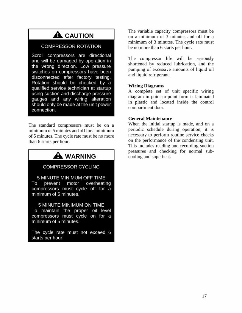
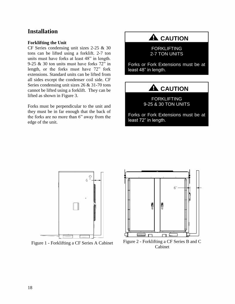
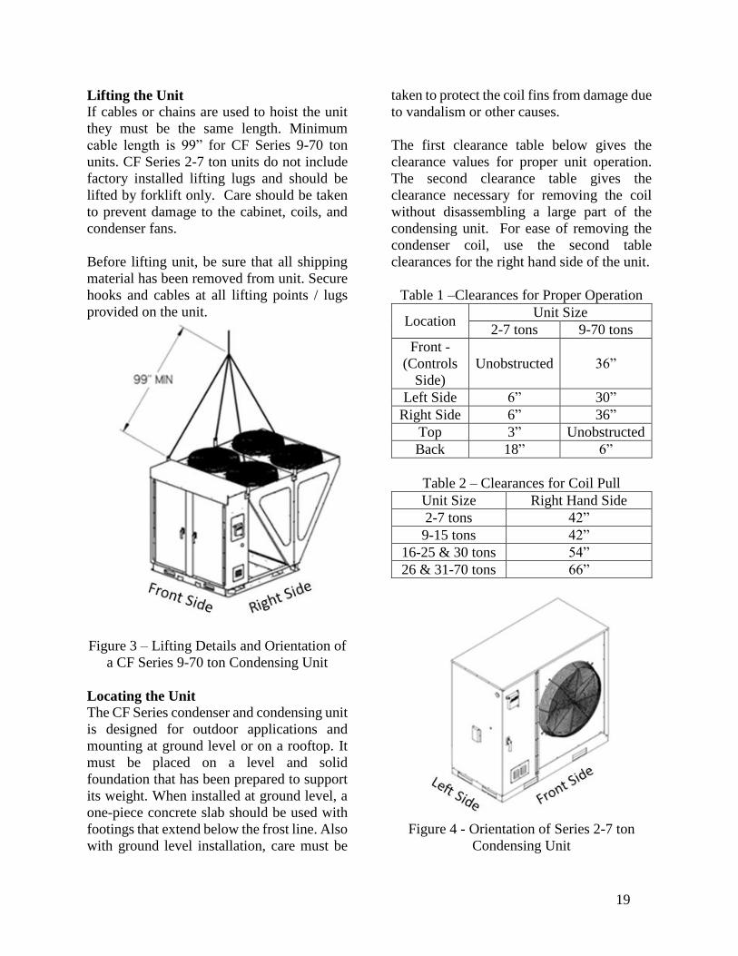
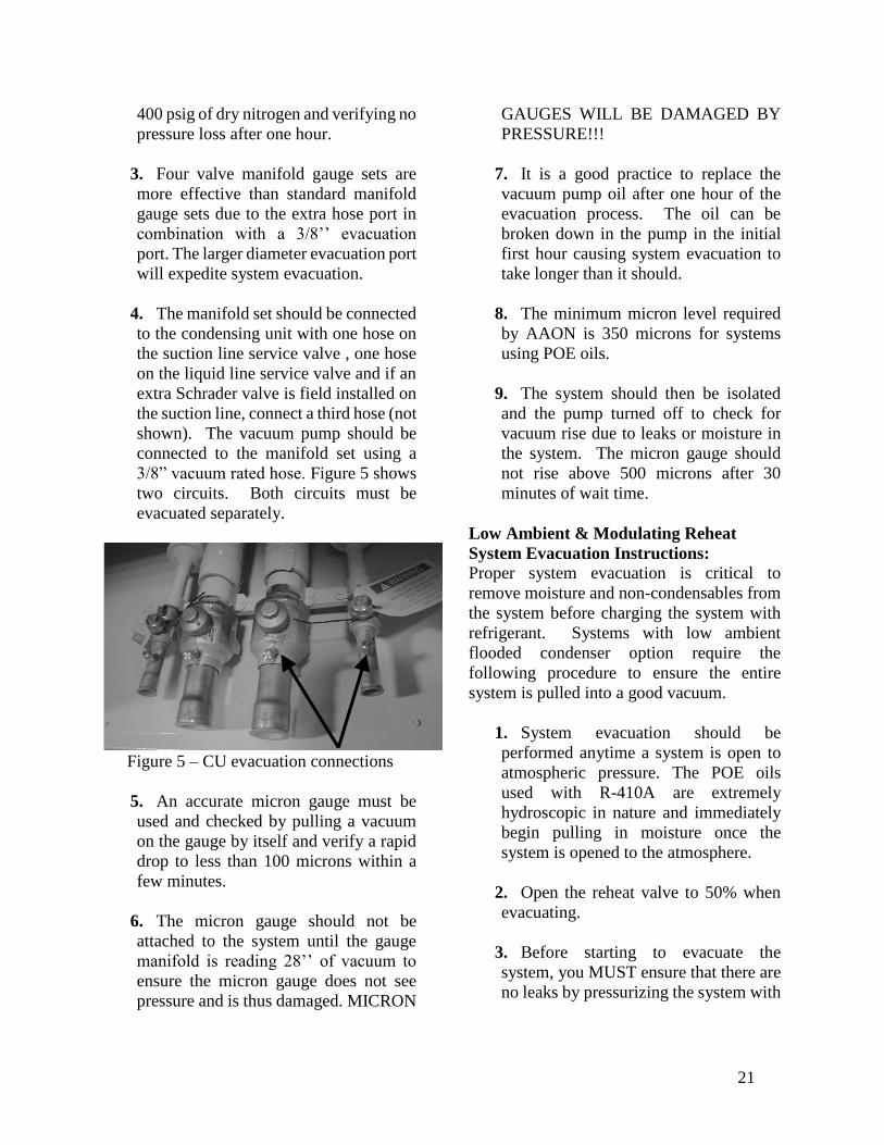
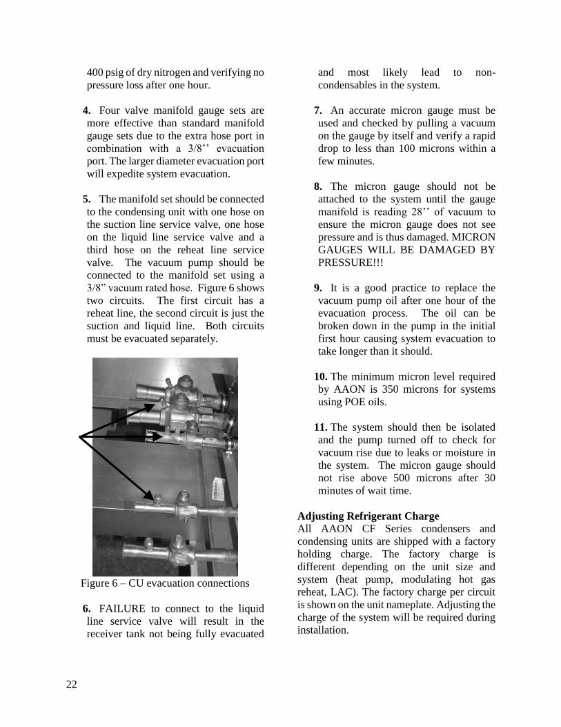
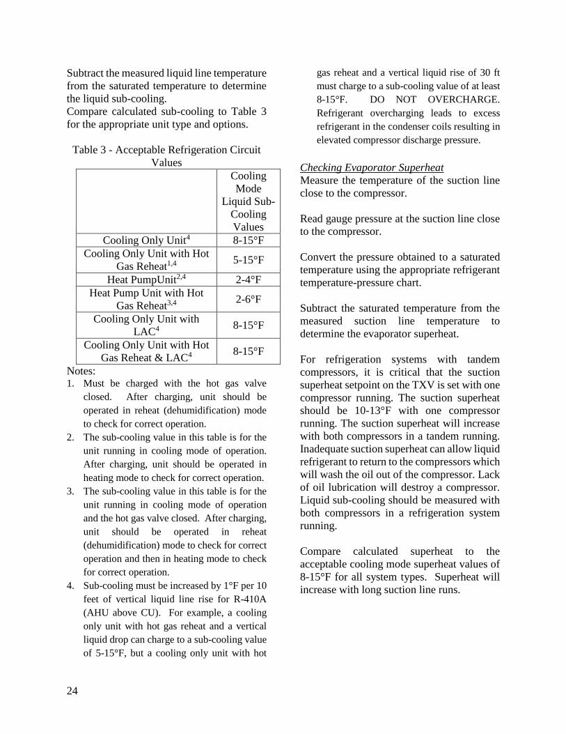
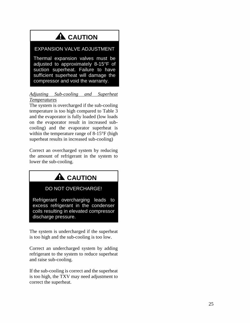
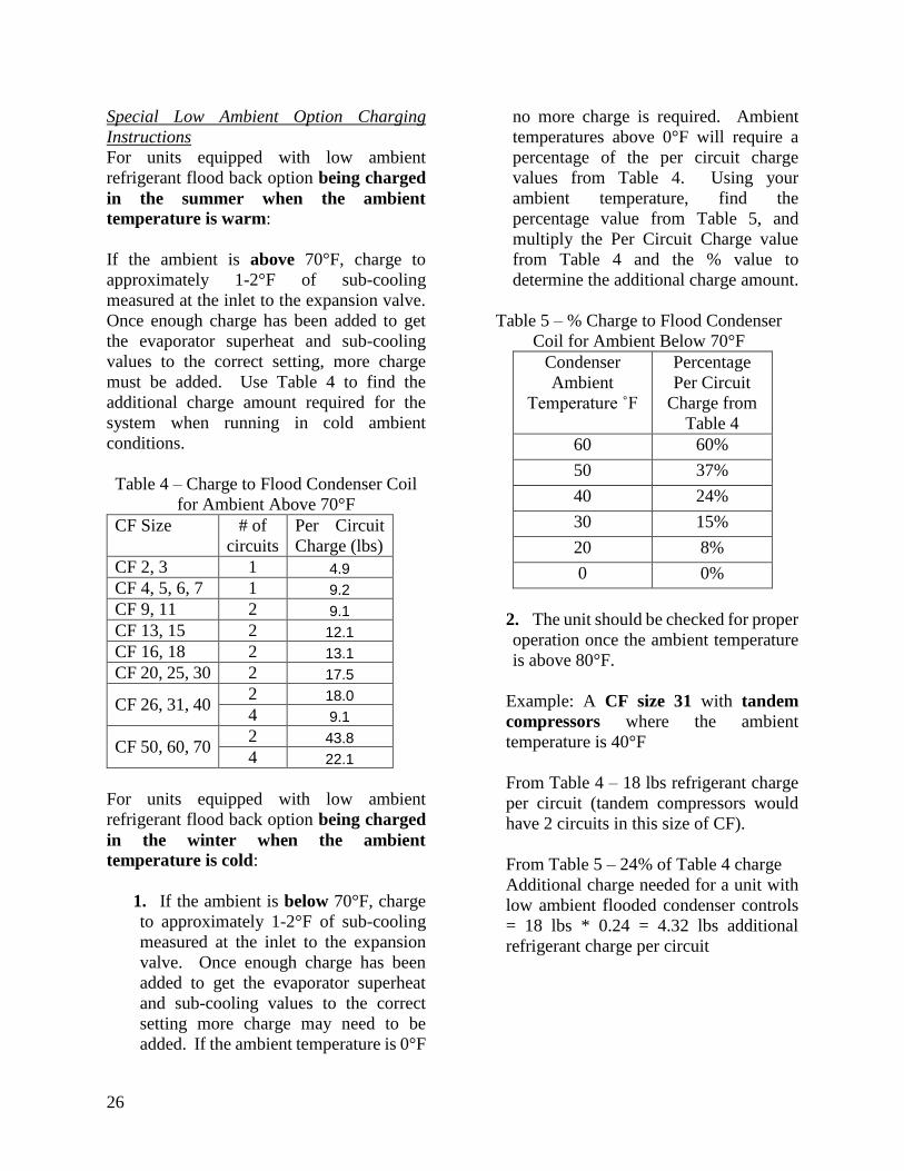
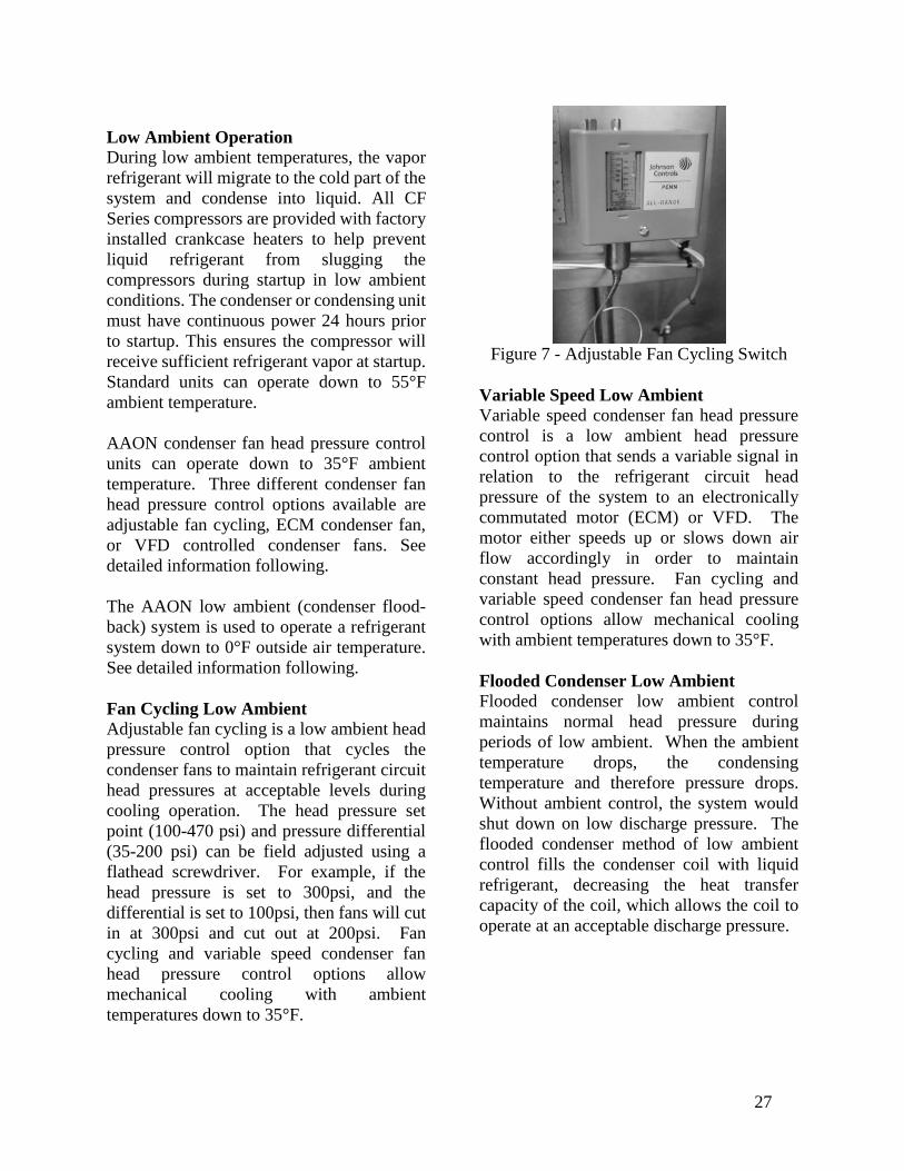
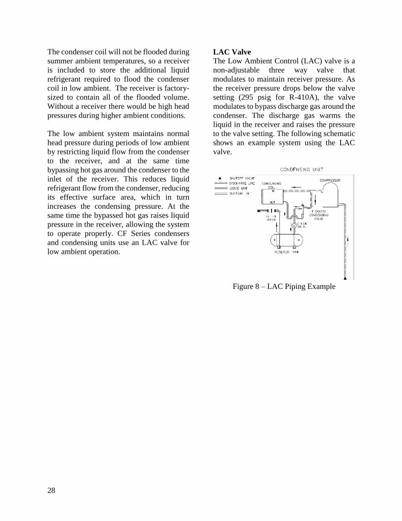
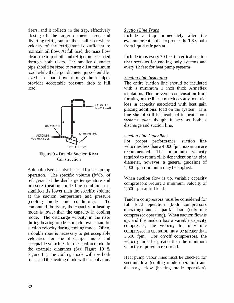
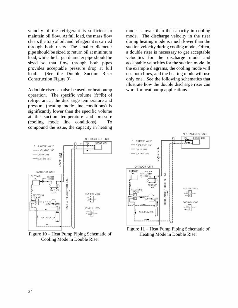
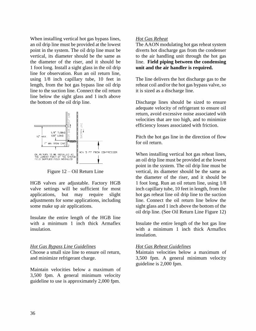
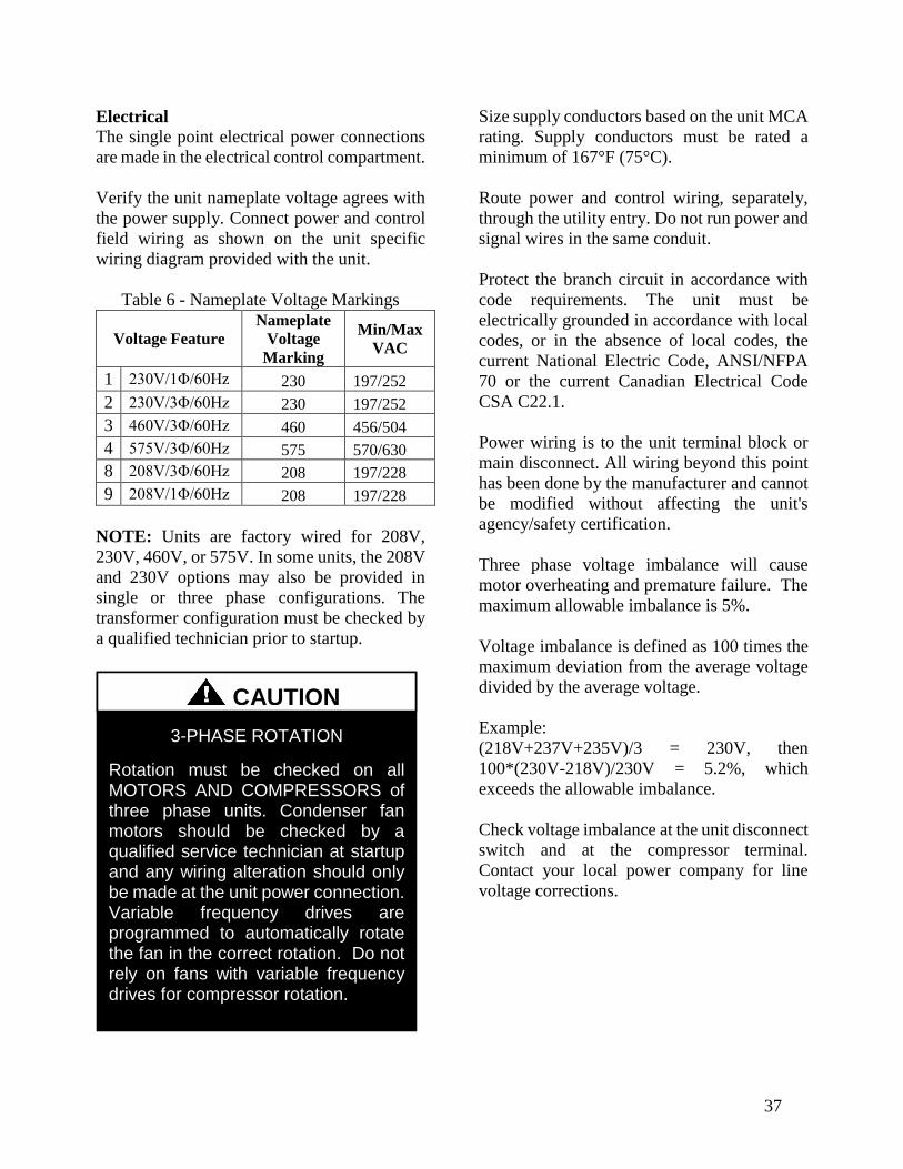
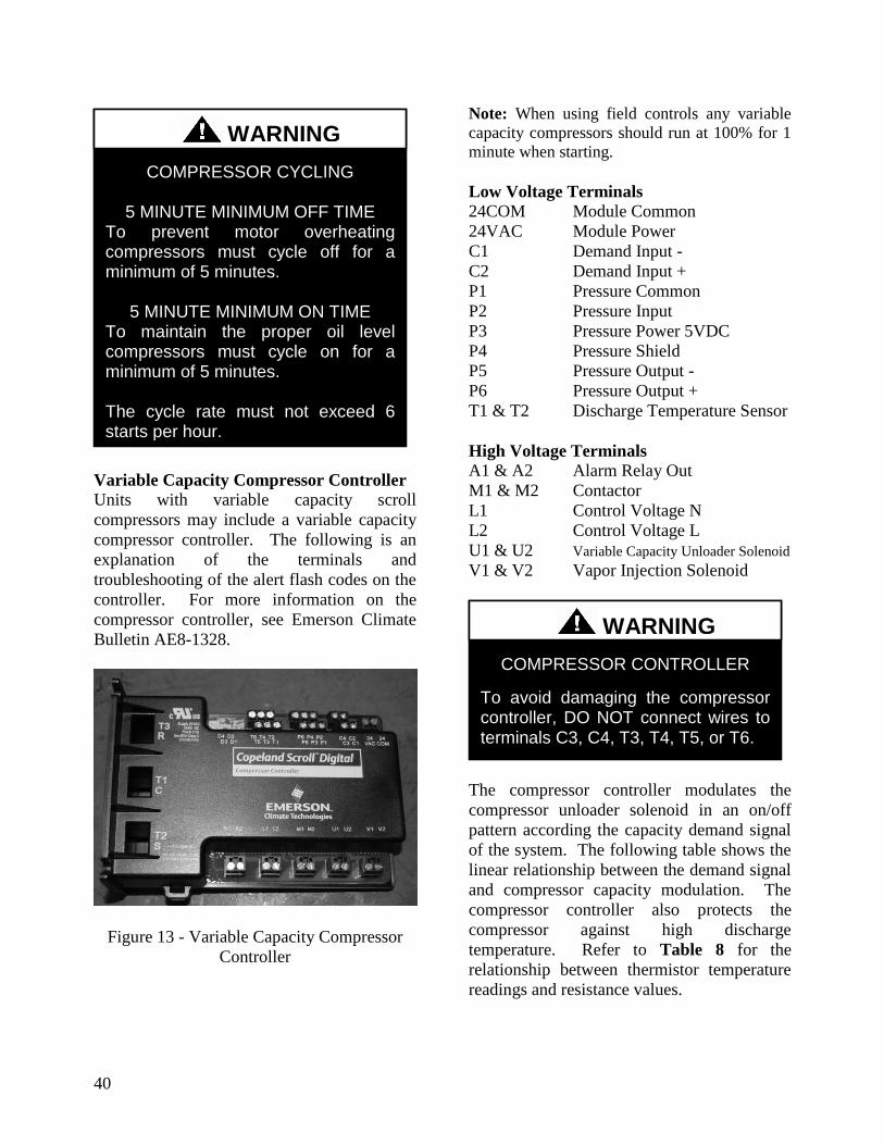
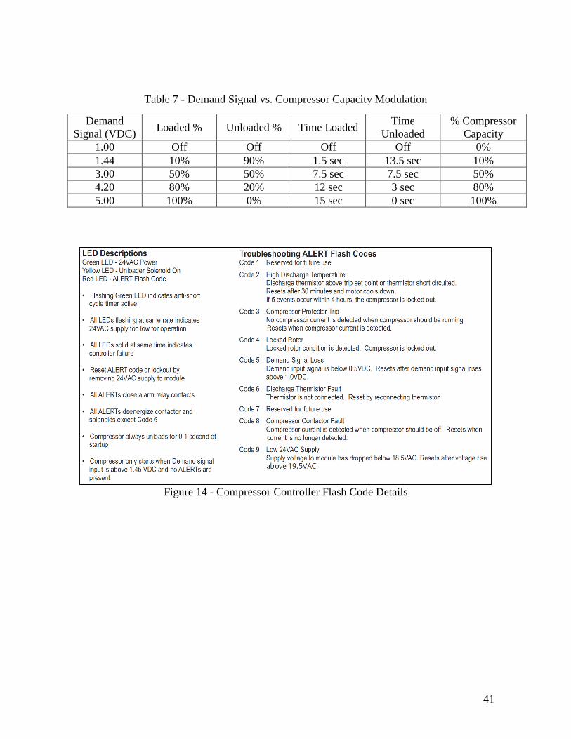
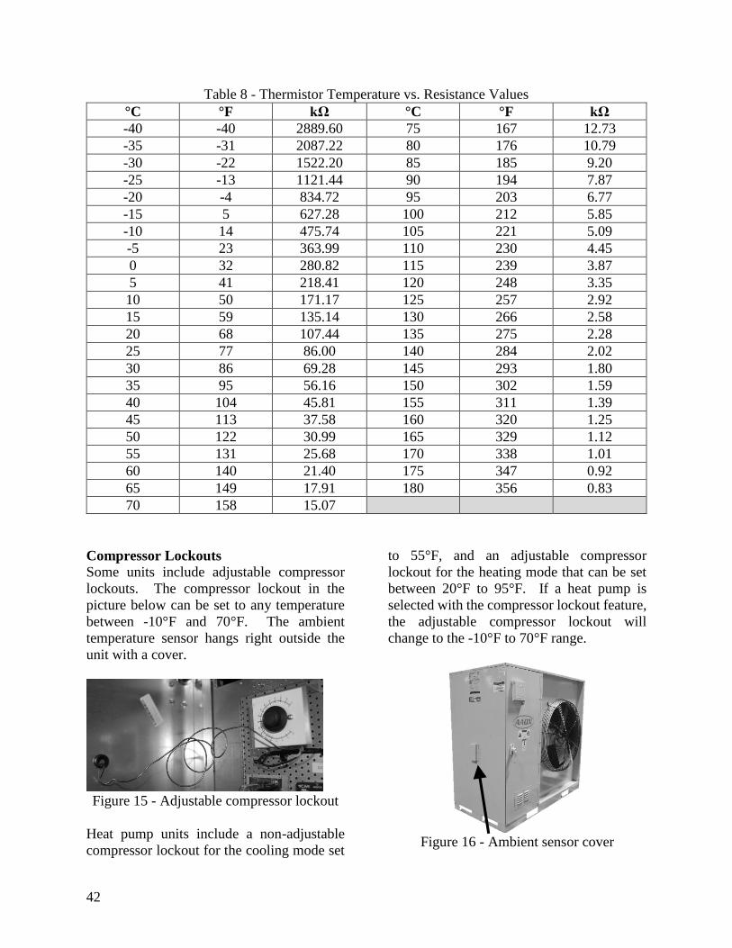
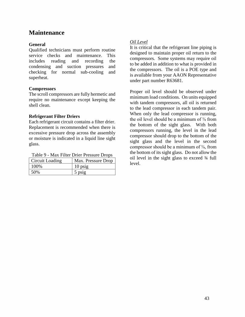
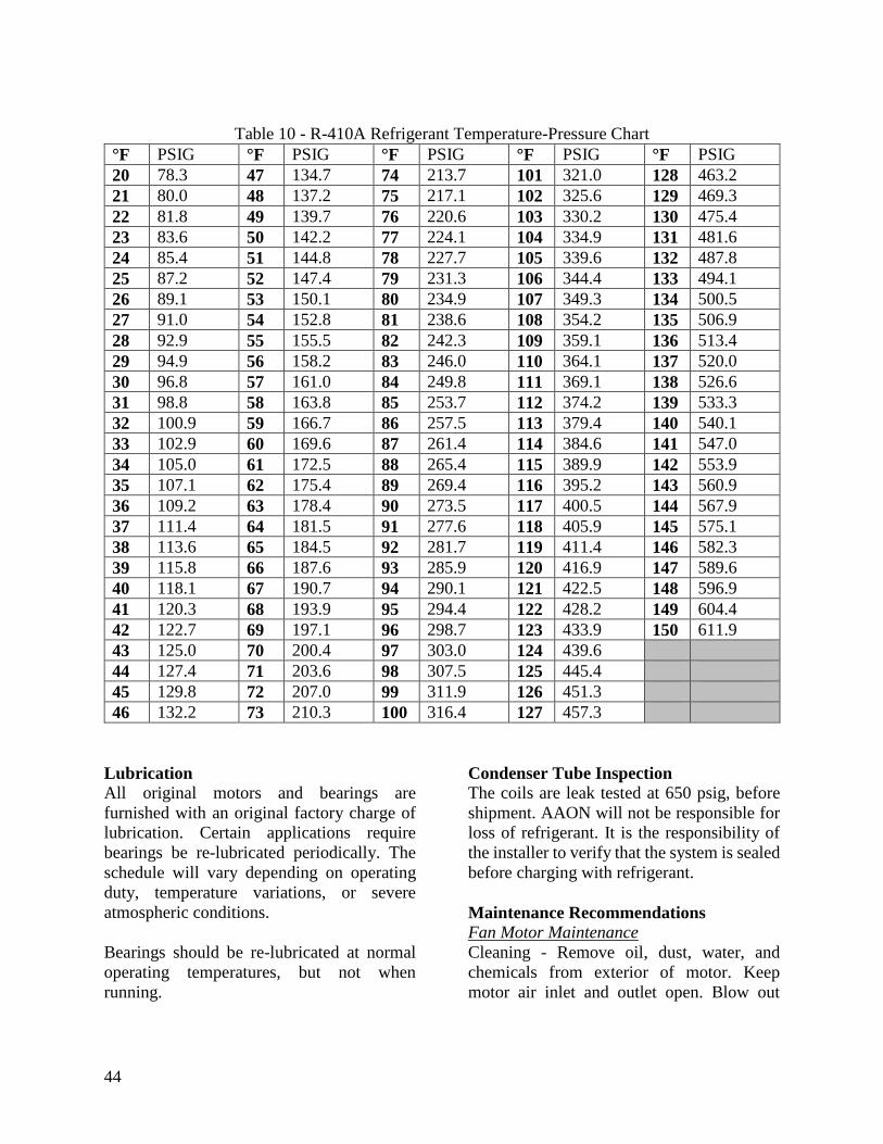
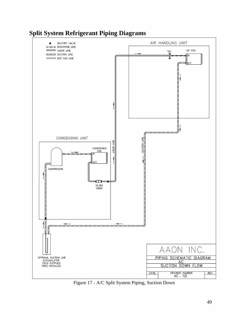
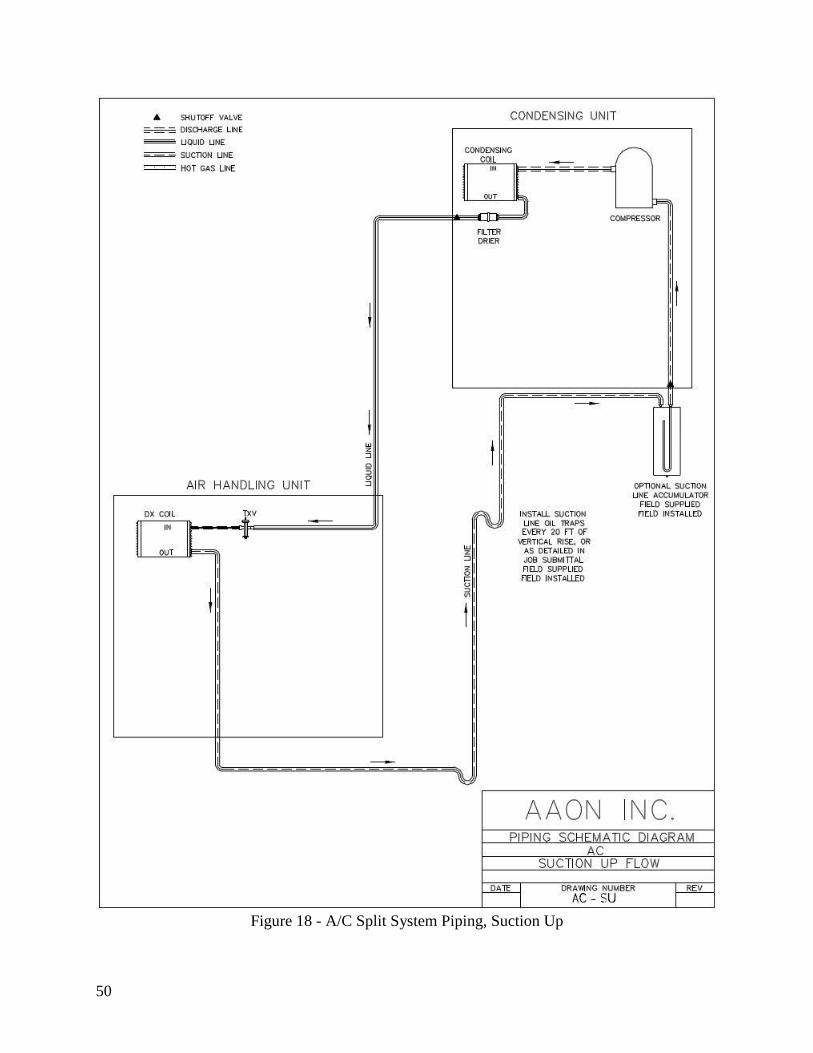
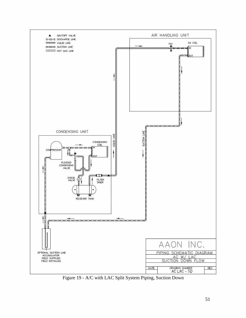
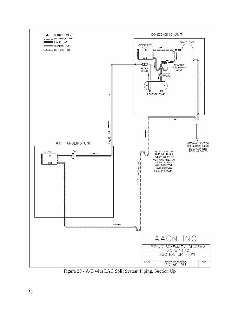
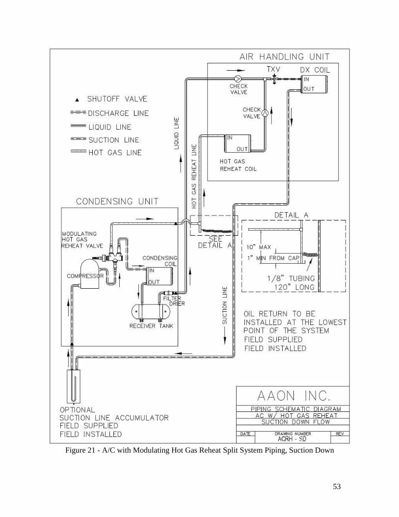
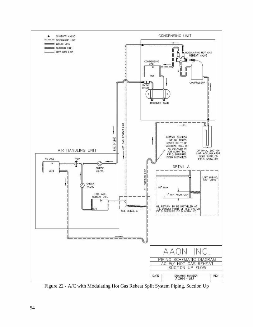
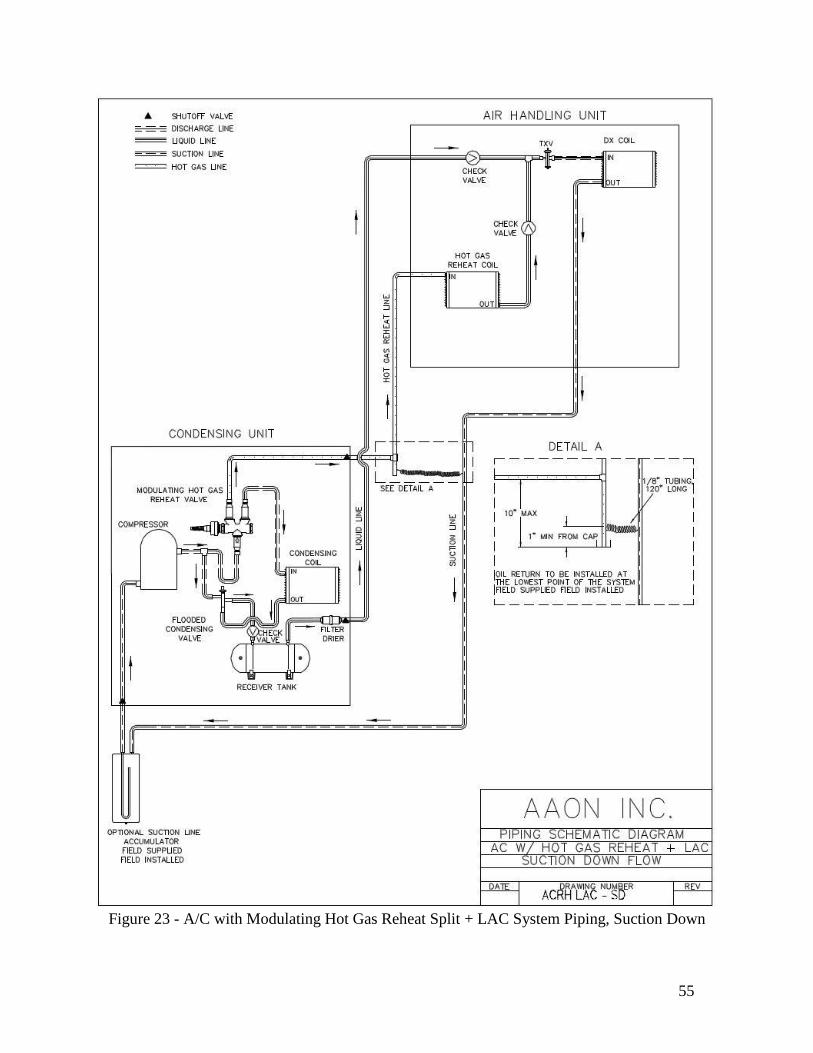
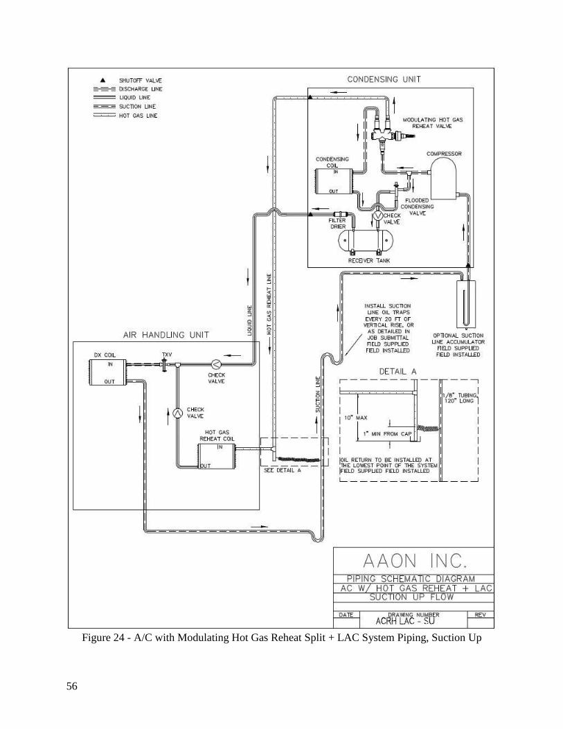
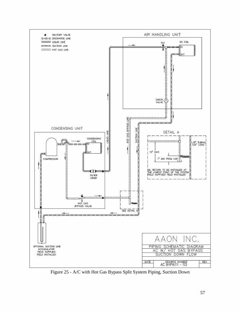
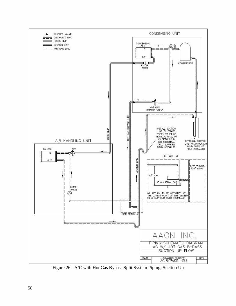
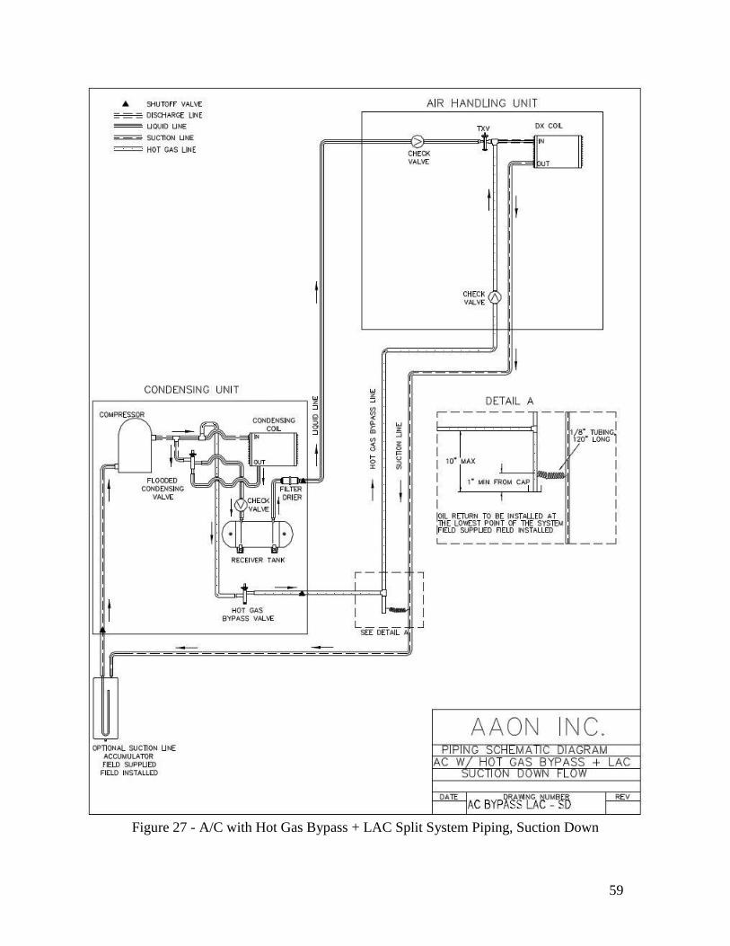
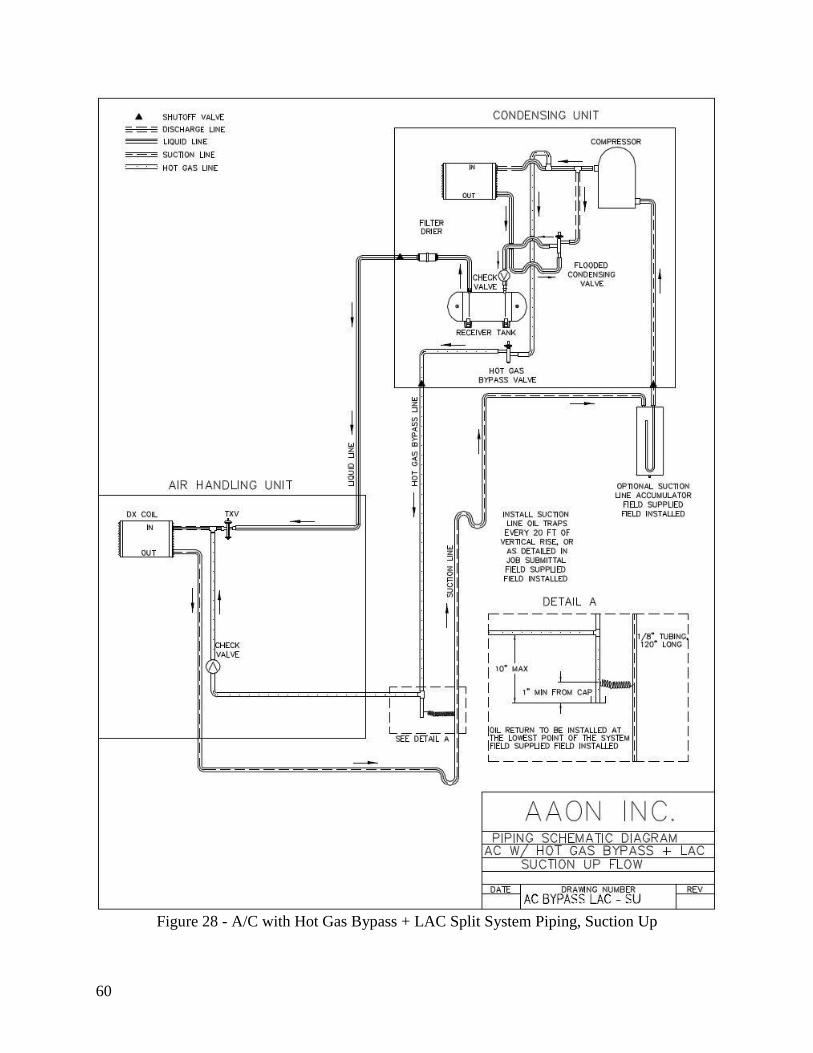
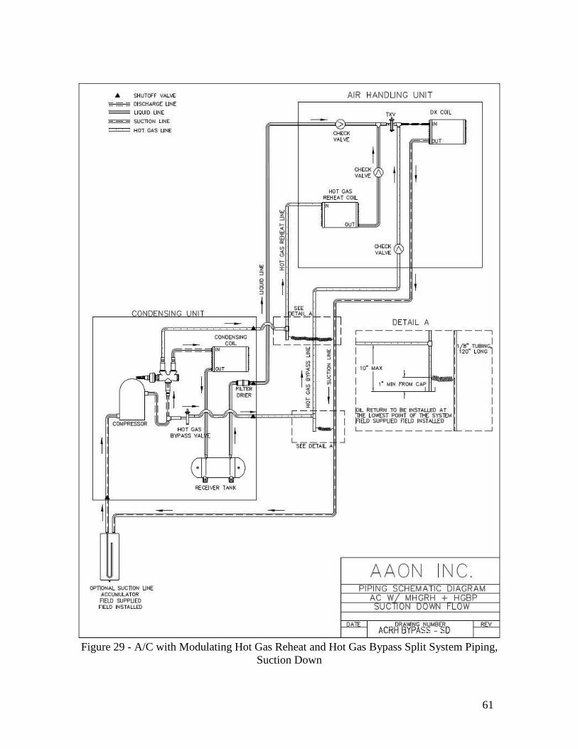
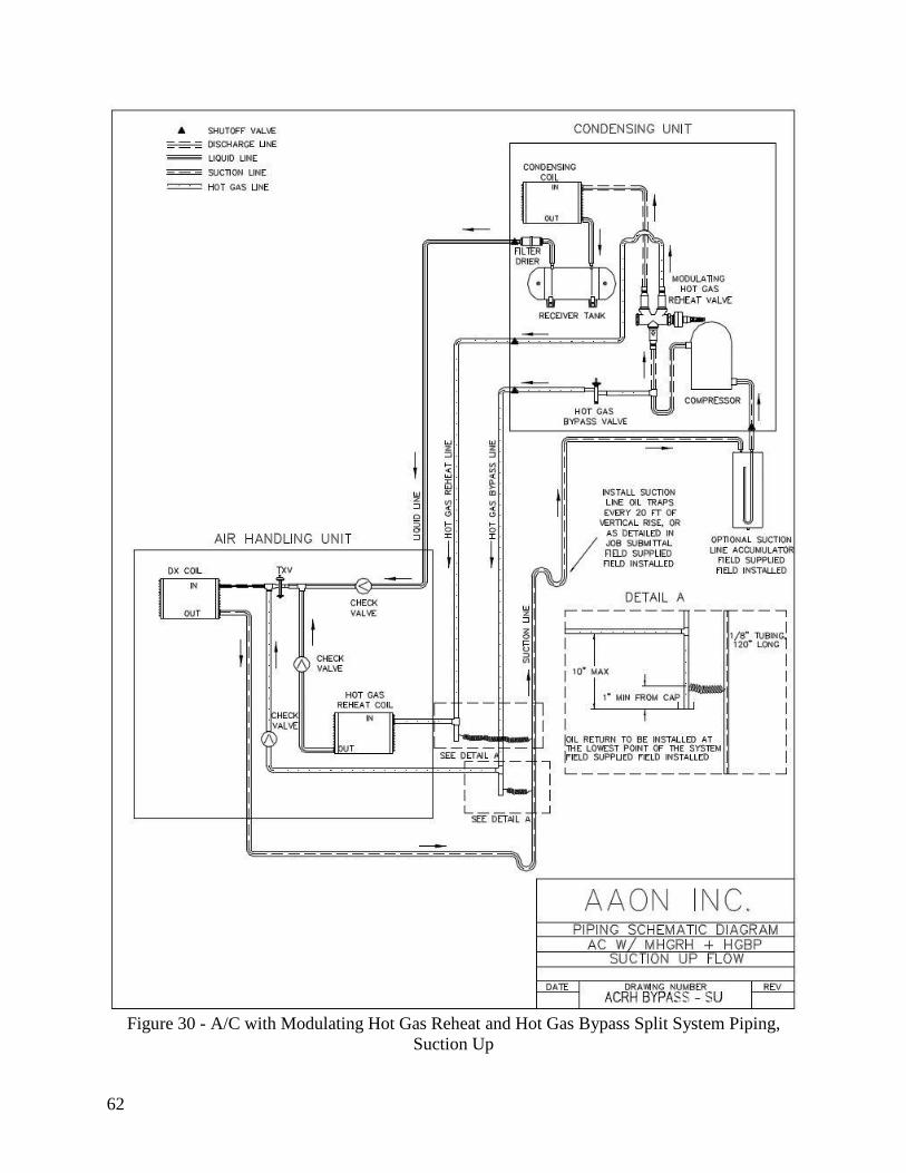
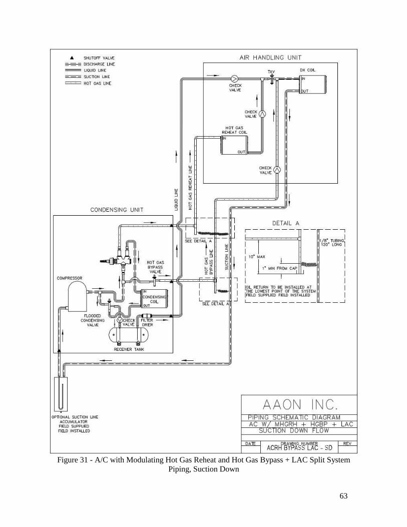
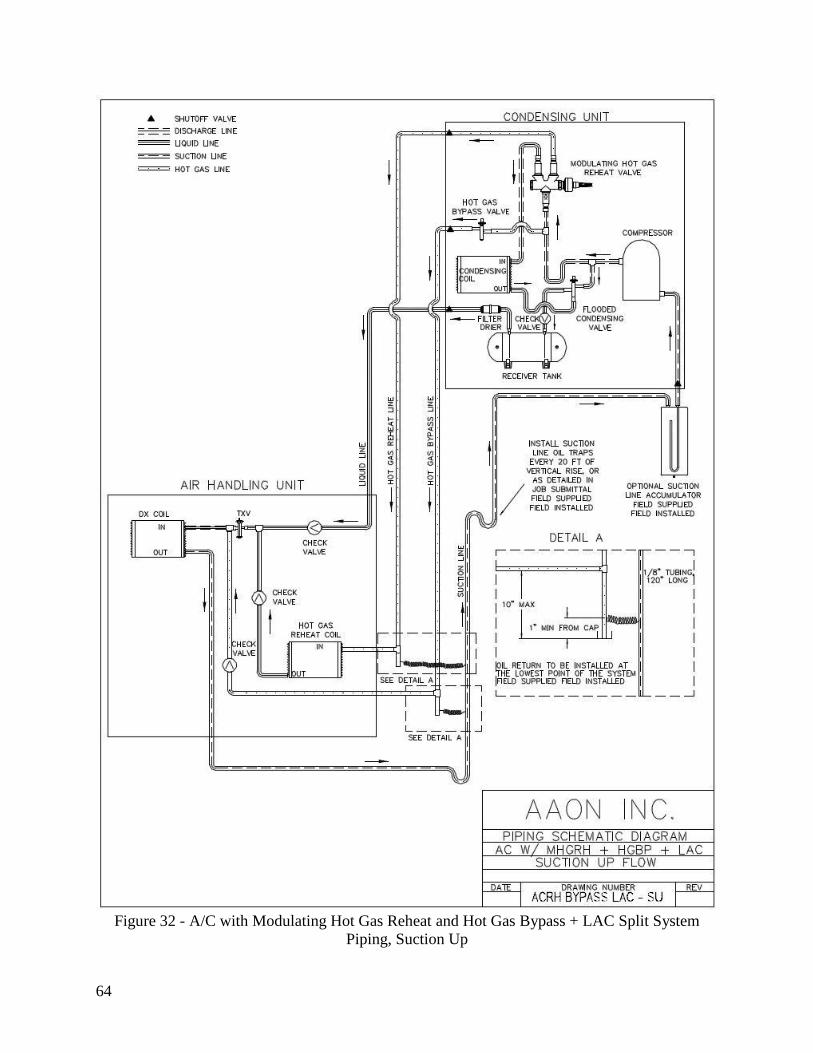
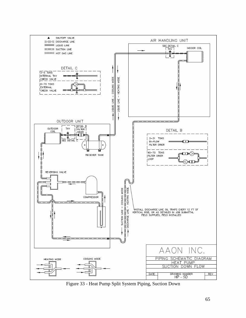
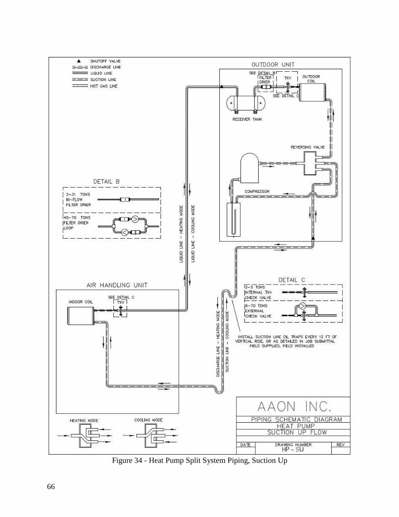
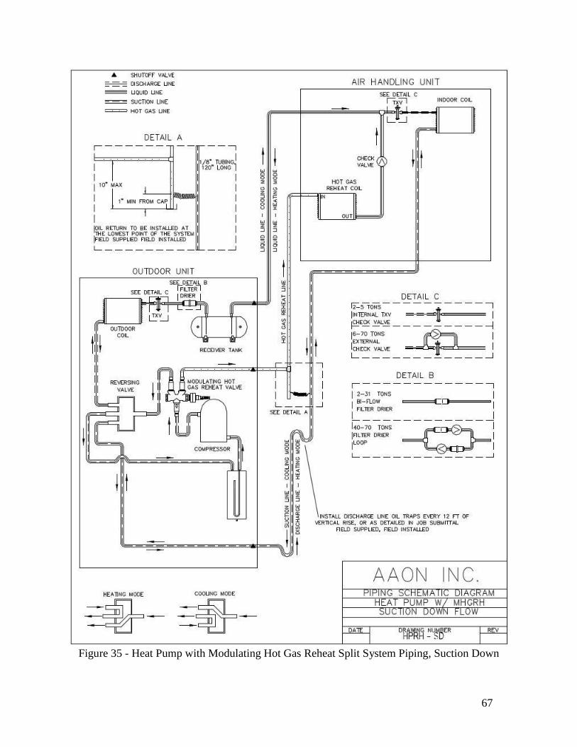
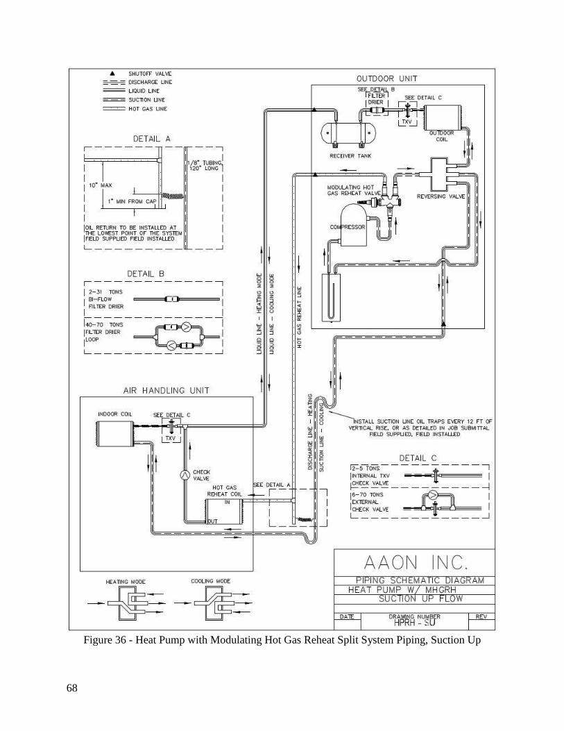
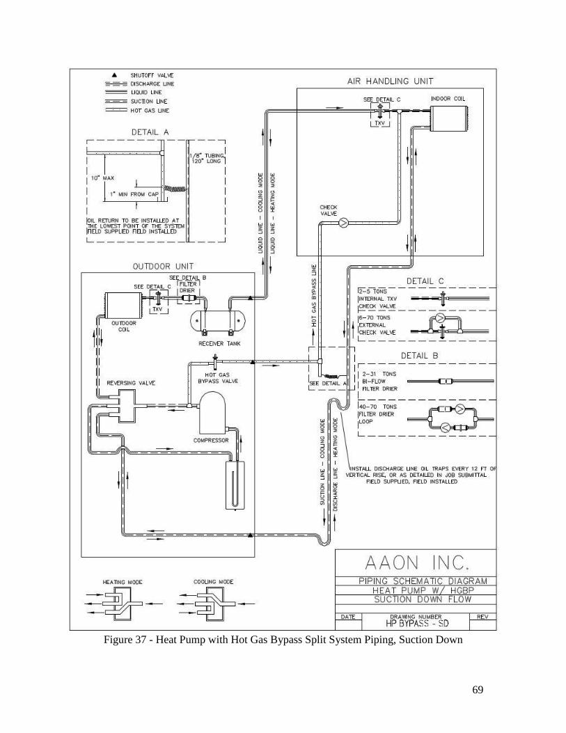
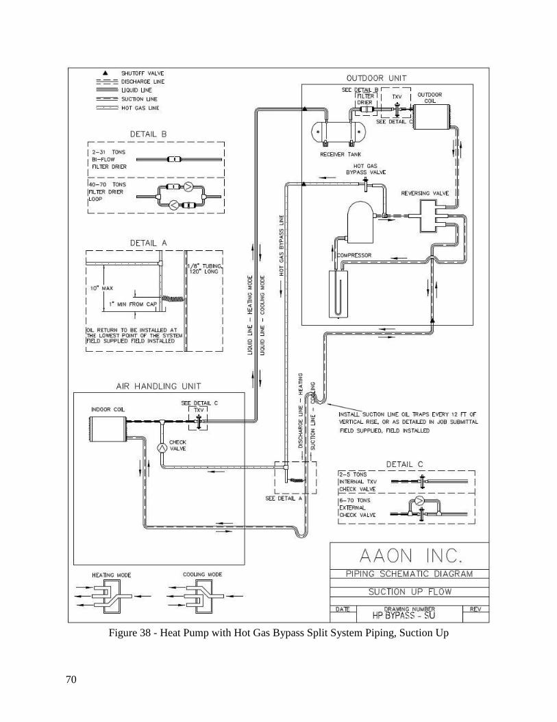
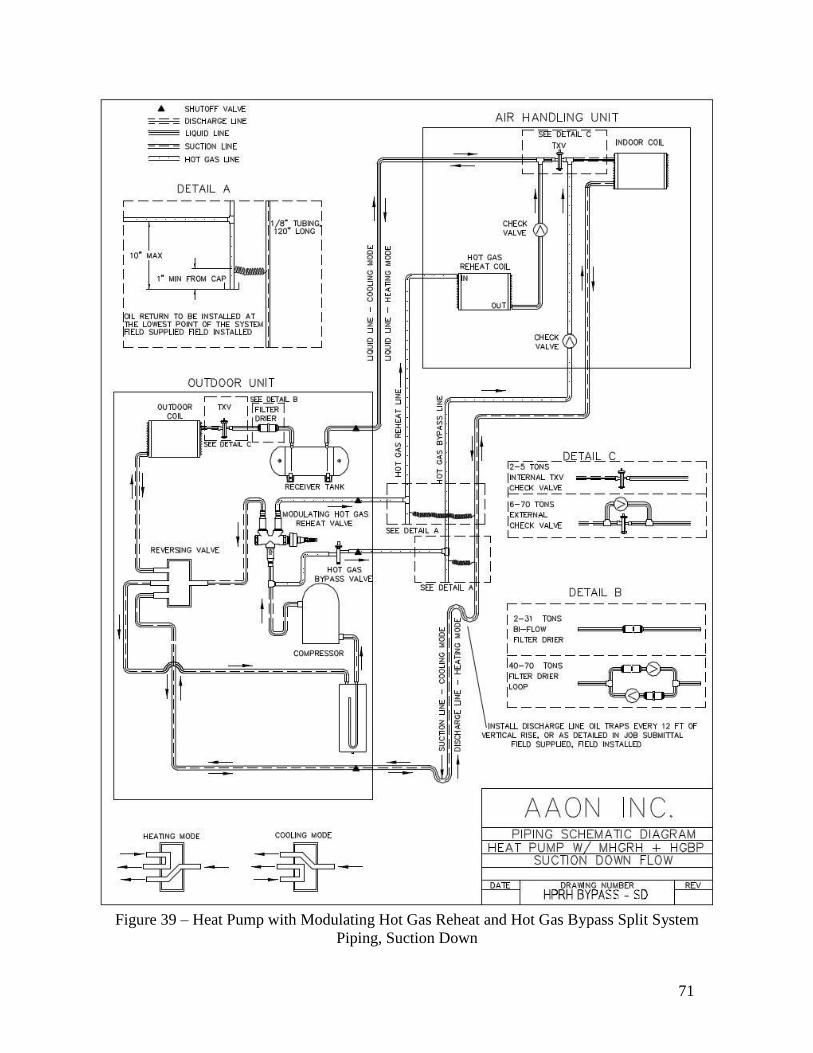
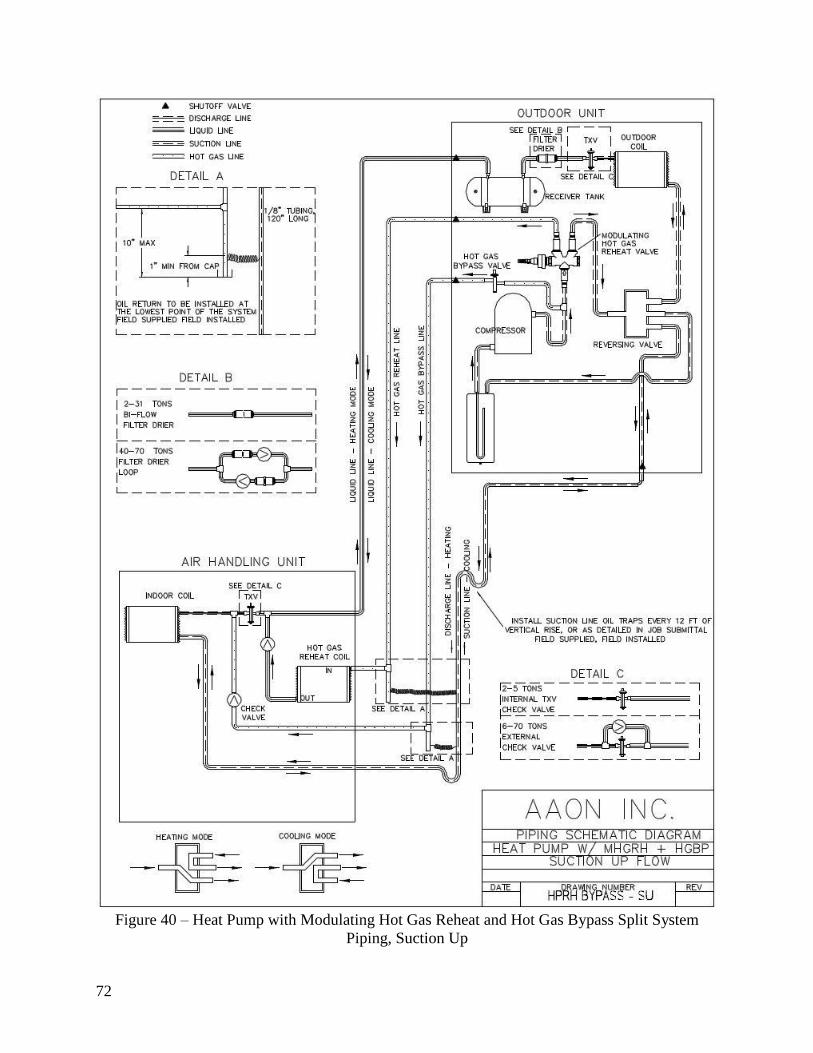
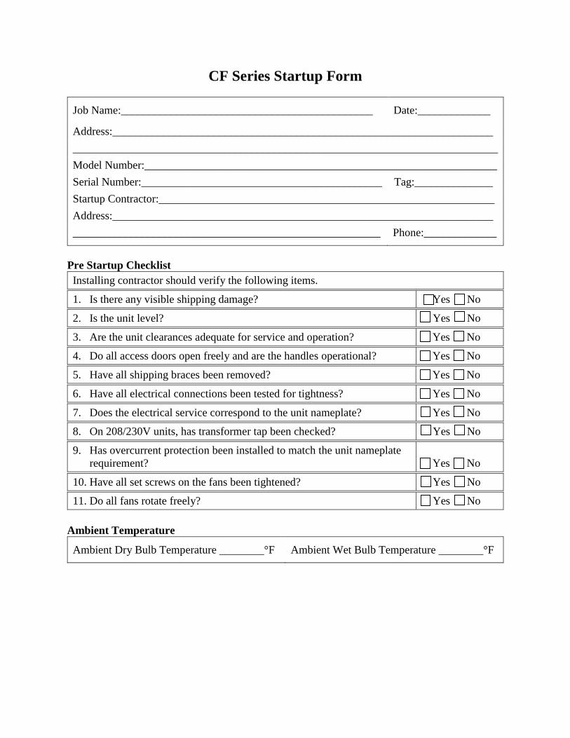
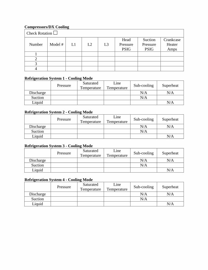
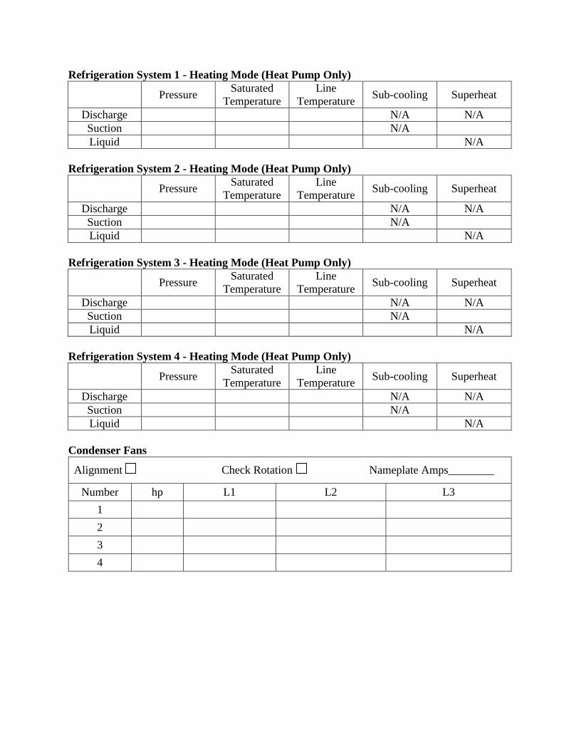
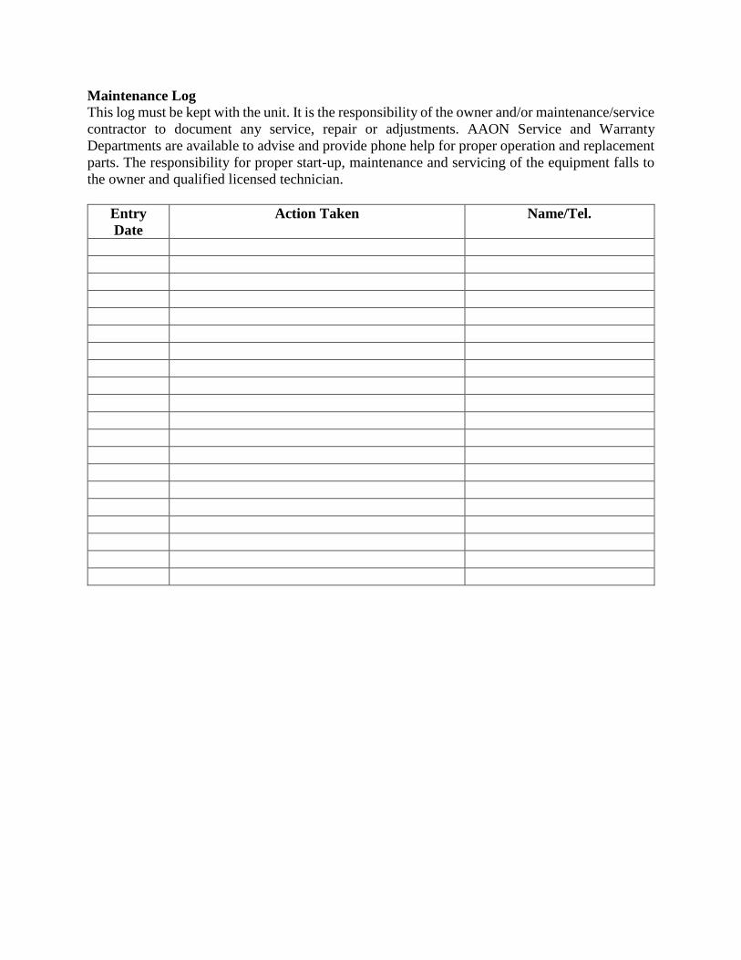