concrete block paving for airfields · 2012-12-10 · this specification, " concrete block...
TRANSCRIPT

Specification 35
Concrete Block Paving for Airfields
DEFENCE ESTATES MINISTRY OF DEFENCE


Specification 35
Concrete Block Paving for Airfields
April 2005
CONSTRUCTION SUPPORT TEAM DEFENCE ESTATES
Ministry of Defence

© Crown Copyright 2005. All Crown Copyrights are reserved. Individuals are authorised to download this text to file or printer for their own individual use. Any other proposed reproduction requires the assent of Defence Estates, Kingston Road, Sutton Coldfield, West Midlands, B75 7RL. Further information is available from www.intellectual-property.gov.uk
First published 1996
Acknowledgements
The specifications in this document have been prepared by TRL Limited in conjunction with and under commission to Construction Support Team, Defence Estates, Ministry of Defence.

April 2005 i
Foreword
This document is for the use of Top Level Budget Holders (TLBHs) for application by the Project Sponsors and their Project Managers, Property Managers (PROM), Establishment Works Consultants (EWC), Works Service Managers (WSM) and other parties involved with airfield pavement works.
This Defence Estates Specification was prepared under the patronage of HQ Strike Command for application to airfield pavement works on the MOD estate.
The application and limitations of the specification requirements in this DE Specification are outlined in Section 1. Further technical assistance regarding the contents of this document can be obtained from DE. Approaches may be made through local DE offices or directly to the airfield pavement Technical Works Authority (DE TA):
Head of Airfield Pavements Construction Support Team Defence Estates Kingston Road Sutton Coldfield West Midlands B75 7RL
Tel: 0121 311 2119 or Sutton Coldfield MI 2119
This Specification, "Concrete Block Paving for Airfields ", has been devised for use of the Crown and of its Contractors in the execution of contracts for the Crown and, subject to the Unfair Contracts Terms Action 1977, the Crown will not be liable in any way whatever (including but without limitation negligence on the part of the Crown its servants or agents) where the Standard is used for other purposes.

ii April 2005
April 2005 iii
Glossary of Technical Terms
Added Filler Filler aggregate that is additional to that inherent in the course and fine aggregate
Aggregate / Cement Ratio
The ratio between the total mass of aggregate, including the mass of any absorbed water, in a concrete mix and the mass of cement in the mix.
Asphalt A mixture of coarse and fine aggregate, filler aggregate and bituminous binder used in the construction of flexible pavements for roads and airfields.
Asphalt Concrete An asphalt mixture consisting of continuous graded aggregate, filler aggregate and bituminous binder proportioned to produce a dense and impermeable surfacing.
Asphalt Surfacing A porous friction course, surface course, or a combination of these, and a binder course.
Asphaltic Concrete Alternative name for ‘Asphalt Concrete’.
Base Structural layer(s) of a pavement immediately below the Binder Course that are bound.
Basecourse Previous name for ‘Binder Course’.
Bay (of Concrete) The area of slab bounded by adjacent pairs of longitudinal and transverse joints or grooves.
Bay Layout The pattern of joints and grooves on a concrete pavement.
Binder A material used for the purpose of holding solid particles together as a coherent mass.
Binder Course The layer or layers of the asphalt surfacing immediately below the surface course. (Previously called ‘Basecourse’).
Bitumen Binder obtained from crude oil by refinery processes.
Bitumen Emulsion An emulsion in which bitumen is dispersed in water or in aqueous solution with the aid of suitable emulsifying agents.
Bitumen Macadam See ‘Macadam’.

iv April 2005
Bituminous Containing bitumen. (Previously included road tar, pitch or mixtures thereof).
Bituminous Surfacing Alternative name for ‘Asphalt Surfacing’.
Bond Coat Proprietary bitumen spray that provides additional adhesion and imperviousness to that achieved with a Tack Coat and, therefore, improved bond between layers when applied at the rate of application recommended by the proprietor for the particular situation.
Coarse Aggregate For asphalt, aggregate mainly retained on a 2.0 mm test sieve and containing no more finer material than is permitted for the various sizes in BS EN 13043. For concrete and block making, aggregate mainly retained on a 4.0 mm test sieve and containing no more finer material than is permitted for the various sizes in BS EN 12620.
Cold Recycled Bound Material (CRBM)
A material produced ex situ in a fixed or mobile mixing plant from recycling base and binder courses from existing pavements. The recycling process allows for the crushing, screening and grading of excavated material, blended if necessary with other aggregate, and bound with bituminous and hydraulic binder(s) including cement.
Construction Joint A joint separating area of a concrete pavement slab placed during different pours, usually on different days. May be a longitudinal, or lane, joint or a transverse joint across a lane.
Contraction Groove A groove formed in the surface of a concrete slab, either during or soon after laying, in order to induce shrinkage cracking to occur in a controlled manner. Usually formed transversely at regular intervals along a lane of concrete by saw cutting so as to subdivide it into approximately square bays.
Crushed Aggregate Aggregate produced by crushing rock or gravel.
Cutback Bitumen Bitumen whose viscosity has been reduced by the addition of a suitable volatile diluent.
Dense Bitumen Macadam (DBM)
See ‘Macadam’.
Drylean concrete A cement bound granular material with low water content suitable for use as a Base or subbase. Unlike conventional concrete, it is usually compacted by rolling.

April 2005 v
Edge Restraint Device that serves to prevent sideways movement of paving units and prevents loss of material from the laying course, base or subbase.
Expansion Joint Joint provided in a concrete pavement to accommodate the expansion which occurs when the temperature of the pavement rises.
Filler Aggregate For asphalt, aggregate, most of which passes a 0.063 mm sieve as permitted in BS EN 13043, which can be added to construction materials to provide certain properties. For concrete and block making, aggregate, most of which passes a 0.063 mm sieve as permitted in BS EN 12620, which can be added to construction materials to provide certain properties.
Fine Aggregate For asphalt, aggregate mainly passing a 2.0 mm test sieve and containing no more coarse material than is permitted for the various gradings in BS EN 13043. For concrete and block making, aggregate mainly passing a 4.0 mm test sieve and containing no more coarser material than is permitted for the various gradings in BS EN 12620.
Fines Any solid material passing a 0.063 mm test sieve.
Foreign Object Damage (FOD)
Damage sustained by aircraft as a result of foreign objects striking the aircraft or being ingested into jet engines. Potential sources of damage are generally referred to as FOD hazards.
Free Water/Cement Ratio
The ratio between the mass of water, less any water absorbed by the aggregates, in a concrete mixture and the mass of cement in the mixture.
Friction Course See ‘Porous Friction Course’.
Grading Particle size distribution of an aggregate.
Heavy Duty Macadam (HDM)
See ‘Macadam’.
Hot Rolled Asphalt (HRA)
An asphalt mixture of gap-graded aggregate, filler aggregate and bitumen binder proportioned to a design or recipe to produce a dense and impermeable surfacing material.
Interlock Effect of frictional forces between concrete blocks that prevent them moving vertically in relation to each other.

vi April 2005
Intermediate Restraint Device that is used to provide restraint of concrete block paving units at intervals in the paved surface.
Joint Filling Material Material used to fill the joints between concrete blocks. Often referred to as ‘joint filling sand’.
Joint Width The distance between adjacent concrete blocks or concrete blocks and restraint.
Laitance On a concrete pavement, a thin layer with poor durability formed of fine aggregate, cement and water brought to the surface, usually by overworking.
Lane A longitudinal strip of a pavement layer produced by one pass of a set of paving equipment.
Lane Joint A construction joint between adjacent lanes.
Laying Course Material Layer of material on which concrete blocks are bedded. Often referred to as the ‘bedding sand’ or ‘laying course sand’.
Laying Face Working edge of the wearing surface when concrete blocks are being laid out.
Laying Pattern An arrangement of concrete blocks to form specific patterns for structural requirements.
Macadam An asphalt mixture (nominally an Asphalt Concrete) consisting of graded aggregate coated with bitumen. a. Dense Bitumen Macadam (DBM): A
dense, relatively impermeable, Macadam coated with a bitumen binder and with a filler aggregate content of between 2 % and 9 %.
b. Heavy Duty Macadam (HDM): A dense bitumen Macadam with 40/60 grade bitumen binder and a high filler aggregate content of 7 % to 11 %.
c. Pervious Macadam: A layer of 0/32 mm Porous Asphalt which acts as a topping to protect whilst allowing free penetration of the surface water to French drains.
Marshall Asphalt An Asphalt Concrete designed to achieve specified stability, flow, voids and density characteristics.
Particle Size Fraction That portion of aggregate which passes one sieve but is retained on the adjacent smaller sized sieve in the sequence of sieves used to specify that grading.

April 2005 vii
Pavement A structure consisting of a layer or superimposed layers of selected materials, whose primary purpose is to distribute the applied load to the Subgrade.
Pavement Quality Concrete (PQC)
A cement concrete of a suitable quality for use as the surfacing on airfield pavements.
Pervious Macadam See ‘Macadam’.
Petroleum Bitumen See ‘Bitumen’.
Porous Asphalt An asphalt mixture consisting of gap-graded aggregate and binder with a relatively open structure that is pervious to air and water.
Porous Friction Course A relatively thin layer of 2/10 mm aggregate sized Porous Asphalt that allows free penetration of the surface water to the underlying impervious surface course.
Quick Visco-Elastic (QVE)
Type of CRBM in which the primary binder is bitumen but also includes a proportion of Portland Cement.
Ramp A section of pavement, usually laid at a gradient near the maximum permissible, which accommodates differences in level between adjacent pavements. (Note that, in US terminology, ‘Ramp’ may also be used to indicate an aircraft parking area).
Regulating Material Asphalt of variable thickness applied to an existing pavement to adjust the shape preparatory to resurfacing.
Road Tar A viscous liquid derived from crude tar obtained by the destructive distillation of coal which was, but is no longer, used as a component in asphalt.
Roadbase Previous name for ‘Base’.
Sand (for making concrete)
Now called ‘Fine Aggregate’.
Sieved Fraction Previous name for ‘Particle Size Fraction’.
Stone Mastic Asphalt (SMA)
A dense gap-graded asphalt with aggregate-to-aggregate interlock that includes fibres as a stabilising additive to carry the binder without drainage.
Subgrade Upper part of the soil, natural or constructed, that supports the loads transmitted by the overlying pavement.

viii April 2005
Surface Course The layer of the asphalt surfacing immediately below the porous friction course or which directly supports the traffic. (Previously called ‘Wearing Course’).
Tack Coat A thin film of bitumen emulsion to improve the adhesion between two courses of asphalt or between an existing surface and a new asphalt layer.
Thin (Asphalt) Surfacing System
A proprietary asphalt product with suitable properties to provide a surface course that is laid at a nominal depth of less than 50 mm (previously limited to 40 mm).
Uncrushed Aggregate Aggregate resulting from the natural disintegration of rock.
Wearing Course Previous name for ‘Surface Course’.
(NOTE. This glossary is common to all DE Sprecifications for asphalt, block paving and concrete pavement materials and the Project Manager should delete any terms not applicable to a particular project and should add any terms necessary due to the particular nature of that project.)

April 2005 ix
Contents
Page
Foreword i
Glossary of Technical Terms iii
Contents ix
1 Introduction 1 1.1 Background 1 1.2 Functional Requirements of Airfield Pavements 1 1.3 Use of Concrete Block Paving 1 1.4 Design of Pavements with Concrete Block Paving 2 1.5 For Works of Small Scope 2 1.6 Specification Clauses for Concrete Block Paving 2 1.7 Advice from Construction Support Team, DE 2
2 General 3 2.1 References 3 2.2 Overall Requirements 3 2.3 Use of Concrete Block Paving 3 2.4 Quality Assurance for the Supply of Concrete Blocks 3 2.5 Laying of Concrete Blocks 3
3 Concrete Blocks 4 3.1 General 4 3.2 Requirements for Component Materials 4 3.3 Requirements for Concrete Blocks 5 3.4 Site Sampling, Testing and Inspection of Concrete Blocks 5
4 Other Materials 7 4.1 General 7 4.2 Laying Course Material 7 4.3 Joint Filling Material 7 4.4 Elastomeric Joint Sealer 7 4.5 Site Sampling and Testing 7
5 Edge and Intermediate Restraints 9 5.1 General 9
6 Plant and Workmanship 10 6.1 General 10 6.2 Weather Conditions for Laying 10 6.3 Surface Level Tolerance on New Base Construction 10 6.4 Regulation of Existing Surfaces 10 6.5 Fuel Resistant Seal Coat 10 6.6 Reduction of Existing Surfaces 10 6.7 Preparation of Existing Surfaces 10 6.8 Laying Course Material 11 6.9 Block Laying 11 6.10 Compaction and Joint Filling of Concrete Block Paving 12 6.11 Finished Levels and Surface Regularity 12 6.12 Joint Sealing 12 6.13 Trafficking of Block Paving by Contractor's Plant 13

Page
x April 2005
7 Trials 14 7.1 General 14 7.2 Laying Course Material 14 7.3 Block Laying, Compaction and Joint Filling 14 7.4 Joint Sealing 14 7.5 Approval of Trial Area 14
8 Summary of Tests 15 8.1 Test Results 15 8.2 Initial Approval of Concrete Blocks 15 8.3 Initial Approval of Other Materials 16 8.4 Site Sampling and Testing 16
Appendix A – Use of Magnesium Sulphate Soundness Test with Non-Standard Aggregate Fractions 18 A.1 Scope 18 A.2 Apparatus and Reagents 18 A.3 Preparation of Test Portions 18 A.4 Preparation of Fine Aggregate Test Specimens for Each
Fraction 18 A.5 Preparation of Coarse Aggregate Test Specimens for Each
Fraction 19 A.6 Procedure 19 A.7 Calculation and Expression of Test Results 19 A.8 Precision 19 A.9 Test Report 20
Appendix B – Procedure for Establishing Non-Susceptibility of Concrete Mixture to Alkali-Silica Reaction 22 B.1 Scope 22 B.2 Criteria 22 B.3 Procedure 22
Appendix C – Test Method for Straightedge 23 C.1 Scope 23 C.2 Apparatus 23 C.3 Procedure 23
Appendix D – Determination of Mean Surface Texture Depth of Concrete Blocks 24 D.1 Scope 24 D.2 Limitations 24 D.3 Method 24 D.4 Procedure 24 D.5 Calculation 24
Appendix X – Design Consideration 25 X.1 Structural design of Pavement 25 X.2 Base Construction and Regulation of Existing Surfaces 25 X.3 Provision of Geotextile Fabric Over Joints/Cracks 26 X.4 Concrete Blocks 26 X.5 Pavement Layout and Concrete Block Laying Pattern 26 X.6 Edge and Intermediate Restraints 27 X.7 Drainage of Laying Course Material 28 X.8 Joint Sealing 28
Appendix Y – Guidance Notes on Quality Systems for Project Managers 43 Y.1 Introduction 43 Y.2 General 43 Y.3 Quality Systems 43 Y.4 Processes Covered under the Quality System 44

Page
April 2005 xi
Y.5 Assessment of Quality Management Systems 44 Y.6 Aspects to Assess Tender Acceptability 45 Y.7 Monitoring the Quality Management System and Processes 46 Y.8 Records 46
Appendix Z – Guidance Notes on the Preparation of Job Specifications 47 Z.1 Concrete Blocks – General 47 Z.2 Concrete Blocks - Coarse Aggregate 47 Z.3 Laying Course Material 47 Z.4 Edge and Intermediate Restraints 48 Z.5 Regulation of Existing Surfaces 48 Z.6 Reduction of Existing Surfaces 48 Z.7 Preparation of Existing Surfaces 48
References 50

xii April 2005

Specification 35 Concrete Block Paving for Airfields 1 Introduction
April 2005 1
1 Introduction
1.1 BACKGROUND
1.1.1 The unique characteristics of military aircraft, in terms of speed, weight, tyre pressures, etc., create specialist requirements in the surfacing of MOD airfields. As such, specialist materials specifications are required to meet these needs.
1.1.2 This Standard, for Concrete Block Paving, is one of a series being produced by DE to lay down specification requirements for airfield pavement works. The following clauses in this Section are intended to set out the applications of Concrete Block Paving in the construction and refurbishment of MOD airfield pavements.
1.1.3 The use of this Standard does not absolve a Project Manager from any responsibility for his designs, neither does its existence constrain him from using alternatives, provided such alternatives can be demonstrated to provide a result of equal quality.
1.2 FUNCTIONAL REQUIREMENTS OF AIRFIELD PAVEMENTS
The pavements must facilitate safe aircraft ground operations. In order to do this they must meet certain specialist performance requirements. The following sets out the main requirements, the relative importance of which will be dependent on the function of the pavements and the nature and type of aircraft operations: a. Good rideability. b. Good friction characteristics. c. High strengths and stability to withstand the
shear stresses induced by heavy wheel loads and high tyre pressures.
d. A durable, hard-wearing weatherproof surface free from loose material and sharp edges which might endanger aircraft.
e. Resistance to fuel spillage and jet blast. Depending on the nature and type of aircraft operations, these requirements are likely to be too onerous for bituminous surfacings in certain areas of the airfield.
f. Facilitate economic maintenance.
1.3 USE OF CONCRETE BLOCK PAVING
1.3.1 Concrete block paving has been used on airfields in the UK since the early 1980s. On MOD airfields it has been used in about 20 projects for the construction of new or refurbishment of existing pavements; the first two of these were small trial areas constructed in 1984 and 1986 respectively.
1.3.2 The measured approach to the application of this type of construction on MOD airfields has meant that experience of performance is still somewhat limited in relation to use by different aircraft types and use on different areas of an airfield. This experience together with the information from two studies carried out for DEO(W)/ABFG (The Use of Small Interlocking Concrete Blocks for Airfield Pavements - PSA 1991 and Concrete Block Paving for Airfield Pavements – BAA 1994) provide the basis for the comments and recommendations at Clauses 1.3.3 and 1.3.4; the latter review included a number of UK civil airport applications of this type of construction.
1.3.3 The following characteristics and perceived limitations of concrete block paving need to be carefully considered with regard to its use on airfields:
• The limited experience of use of this type of construction on a runway has indicated that when concrete block paving is subject to high jet engine efflux, there is a lack of predictability of performance and a fine margin between it being serviceable and being a major FOD risk. It is considered that the performance of concrete block paving subject to other than low levels of jet efflux or propeller wash is not proven.
• Experience on MOD airfields indicates that it is difficult to achieve a surface regularity equal to that of traditional surfacing materials. The requirement for surface regularity in the Specification has, therefore, been set accordingly; however, the potential impact on surface drainage characteristics must be carefully considered and taken into account in developing suitable pavement designs; Clause X.5 of Appendix X provides further guidance.

Specification 35 Concrete Block Paving for Airfields 1 Introduction
2 April 2005
• A critical factor in the performance of concrete block paving is the stability and durability of the laying course material. The requirements set for the laying course material in the Specification represent a significant upgrade on that previously used for concrete block paving on MOD airfields. However, the performance limit, particularly in the context of regular usage either by very heavy aircraft or aircraft with high tyre pressures, (i.e. greater than 1.5 MN/m²) is an unknown quantity.
• Careful consideration must be given to the nature and frequency of use of ground equipment and the suitability of the concrete blocks and the laying course material to withstand the anticipated loads.
• It is not prone to degradation from fuel spillage.
• The overall layout/configuration of a pavement with concrete block paving can have a significant effect on the block laying pattern and the 'edge' details, which can in turn significantly affect the performance of the pavement. Clause X.5 of Appendix X provides further guidance.
When laid over existing concrete pavements, experience on MOD airfields indicates that it is not prone to reflective cracking. It should be noted however that it hasn't been standard practice to include regular expansion joints in concrete pavements with a slab thickness greater than 225 mm on MOD airfields for over 30 years.
• It can be constructed relatively quickly and trafficked almost immediately upon completion.
1.3.4 The use of concrete block paving on MOD airfields has been restricted to parking areas/aprons for aircraft and helicopters. Having regard to Clause 1.3.3, it is recommended that this practice should continue until the technology is either further developed or proven in respect of resistance to higher levels of jet efflux and propeller wash and also rideability and drainage characteristics. With regard to the suitability of concrete block paving for use on aprons, each case will have to be considered on its own merits taking account of the following:
• The level of jet efflux or propeller wash, or rotor down-wash from large helicopters.
• The aircraft type with particular regard to magnitude of loading and tyre pressures.
• The frequency of usage.
• The nature and use of ground equipment.
• The layout of the pavement.
• In the past concrete block paving has proved to be a cost effective solution for new aprons for use by light aircraft and small to medium sized helicopters and also for restoring existing
concrete aprons where these are structurally sound.
1.4 DESIGN OF PAVEMENTS WITH CONCRETE BLOCK PAVING
The basic conceptual matters are discussed at Clause 1.3 above. However, careful attention also needs to be given to various aspects of detail design in order for the Specification to be effective. For this purpose, Appendix X provides guidance on the structural design of pavements, materials for base construction, concrete block types, laying patterns of concrete blocks, drainage, edge restraint details and sealing of joints. This guidance is based on experience of performance of pavements on MOD airfields and various Studies/Reviews carried out by Consultants for DEO(W)/ABFG.
1.5 FOR WORKS OF SMALL SCOPE
For works of small scope it may be necessary to modify the Specification in order to achieve a realistic balance between cost and quality requirements. Such considerations may apply to test requirements for component materials for making concrete blocks.
1.6 SPECIFICATION CLAUSES FOR CONCRETE BLOCK PAVING
Specification clauses are contained in Sections 2 to 8 and Appendices A to C of this Standard. Guidance Notes for the Project Manager on pavement design are given in Appendix X, on Quality Systems in Appendix Y and for preparation of job specifications in Appendix Z.
1.7 ADVICE FROM CONSTRUCTION SUPPORT TEAM, DE
Clauses 1.2, 1.3, 1.4 and 1.5 provide general advice on the application of this Standard. However, having regard to the various design parameters affecting the choice of construction and specifications, including scope of work, aircraft type and frequency of usage, location of a pavement on an airfield, design life, timescale constraints and existing pavement constructions, the guidance notes cannot be exhaustive. Further advice on a project/works specific basis can be obtained from the Construction Support Team, DE.

Specification 35 Concrete Block Paving for Airfields 2 General
April 2005 3
2 General
2.1 REFERENCES
All references to British Standards and other documents given in this Specification refer to the editions as listed in the References at the end of this document unless otherwise stated.
2.2 OVERALL REQUIREMENTS
2.2.1 Concrete Block Paving shall be specified, manufactured and laid to the requirements of BS EN 1338 and BS 7533: Part 3 and subject to the additional clauses in this Specification.
2.2.2 The requirements of this Specification are arranged in the following parts:
General Section 2 Concrete Blocks Section 3 Other Materials Section 4 Edge and Intermediate Restraints Section 5 Plant and Workmanship Section 6 Trials Section 7 Tests Section 8
Magnesium Sulphate Soundness Test Appendix A Procedure for Establishing Non-susceptibility of Concrete Mix to Alkali-Silica Reaction Appendix B Straightedge Tests Appendix C
2.3 USE OF CONCRETE BLOCK PAVING
Concrete Block Paving shall be used in the locations where indicated on the project drawings.
2.4 QUALITY ASSURANCE FOR THE SUPPLY OF CONCRETE BLOCKS
2.4.1 All operations in the procurement of component materials and production of concrete blocks shall be carried out by a Manufacturer/Supplier who has a Quality Assurance accreditation to BS EN ISO 9000 for those operations.
(NOTE. Advice for the Project Manager on Quality Systems is given in Appendix Y.)
2.4.2 The factory/production unit involved in the work shall be registered under a Quality Assurance Scheme to BS EN ISO 9000. The Quality Policy Manual/s for the supply of component materials and production of concrete blocks together with other relevant records and certificates are to be submitted at Tender Stage.
(NOTE. The Project Manager should provide a questionnaire requesting the details of information that are required, advice is given in sub-Clauses Y.5.2 and Y.6.4 of Appendix Y.)
2.4.3 The Contractor shall be responsible for providing the test data required under Clause 8.2. The Contractor shall also be responsible for having all other testing carried out in accordance with the requirements of Section 8 and providing the Project Manager with a written copy of the results in accordance with Clause 8.1.
2.4.4 All documentation relevant to the work including test results shall also be available at the factory/production unit for inspection. The documentation including work sheets shall be stored in an easily retrievable form for a minimum of 3 years.
2.5 LAYING OF CONCRETE BLOCKS
The whole of the laying works shall be carried out by a specialist firm who should be a member of the Association of Block Paving Contractors ("Interlay"). With his Tender the Contractor shall provide details of the specialist concrete block laying firm he proposes to use which shall include evidence of the laying firm's experience and that of its key personnel.
Specification 35 Concrete Block Paving for Airfields 3 concrete Blocks
4 April 2005
3 Concrete Blocks
3.1 GENERAL
3.1.1 The concrete blocks shall be produced to comply with and be tested in accordance with BS EN 1338 and subject to the additional requirements in this Specification.
3.1.2 Initial approval of concrete blocks shall be obtained from the Project Manager prior to delivery of blocks to site. Approval will be based on test data and records and samples of blocks supplied to the Project Manager as required at Clauses 3.1.3 and 8.2.
3.1.3 A representative* sample of concrete blocks (i.e. at least 12 No) is to be submitted to the Project Manager for approval in respect of colour, surface texture of upper face and general standard of finish. This is to include compliance with the following requirements:
• surfaces of concrete blocks to be free of defects such as cracking, delamination or flaking;
• the upper face/wearing surface of the paving blocks is to have a uniform and closed surface texture;
• block type(s) including provision of chamfers and nibs as required at Clause 3.3.1.
The approved sample blocks are to be marked accordingly and kept for reference and comparison throughout the Project. * The representative sample is to include for the
range of manufacturing tolerance in respect of surface texture and general standard of finish.
(NOTE. Advice for the Project Manager on surface finish requirements is given in Clause Z. 1 of Appendix Z.)
3.2 REQUIREMENTS FOR COMPONENT MATERIALS
3.2.1 Aggregates used for making concrete blocks shall be clean, hard and durable as defined in Clauses 3.2.2 and 3.2.3. Aggregates shall not contain deleterious materials in such form or such quantity to adversely affect the strength at any age or the durability of the concrete blocks. Weathered rock shall not be permitted.
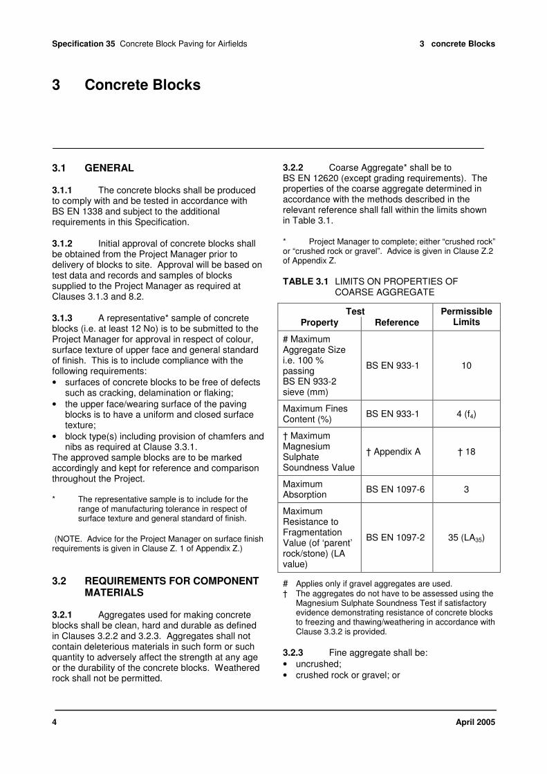
3.2.2 Coarse Aggregate* shall be to BS EN 12620 (except grading requirements). The properties of the coarse aggregate determined in accordance with the methods described in the relevant reference shall fall within the limits shown in Table 3.1.
* Project Manager to complete; either “crushed rock” or “crushed rock or gravel”. Advice is given in Clause Z.2 of Appendix Z.
TABLE 3.1 LIMITS ON PROPERTIES OF COARSE AGGREGATE
Test
Property Reference
Permissible Limits
# Maximum Aggregate Size i.e. 100 % passing BS EN 933-2 sieve (mm)
BS EN 933-1 10
Maximum Fines Content (%)
BS EN 933-1 4 (f4)
† Maximum Magnesium Sulphate Soundness Value
† Appendix A † 18
Maximum Absorption
BS EN 1097-6 3
Maximum Resistance to Fragmentation Value (of ‘parent’ rock/stone) (LA value)
BS EN 1097-2 35 (LA35)
# Applies only if gravel aggregates are used. † The aggregates do not have to be assessed using the
Magnesium Sulphate Soundness Test if satisfactory evidence demonstrating resistance of concrete blocks to freezing and thawing/weathering in accordance with Clause 3.3.2 is provided.
3.2.3 Fine aggregate shall be:
• uncrushed;
• crushed rock or gravel; or

Specification 35 Concrete Block Paving for Airfields 3 Concrete Blocks
April 2005 5
• blends of uncrushed fine aggregate and crushed rock or gravel;
and shall be free from loosely bonded aggregates and other foreign matter. The properties of the fine aggregate, determined in accordance with the methods described in the relevant reference, shall fall within the limits shown in Table 3.2.
TABLE 3.2 LIMITS ON PROPERTIES OF FINE AGGREGATE
Test
Property Reference
Permissible Limits
Maximum Fines Content (%)
BS EN 933-1
3 (uncrushed fine aggregate or crushed gravel fine aggregate)
(f3) 10 (crushed rock fine aggregate)
(f10)
† Maximum Magnesium Sulphate
† Appendix A † 18
Maximum Absorption
BS EN 1097-6 3
† The aggregates do not have to be assessed using the Magnesium Sulphate Soundness Test if satisfactory evidence demonstrating resistance of concrete blocks to freezing and thawing/weathering in accordance with Clause 3.3.2 is provided.
3.2.4 The Contractor shall provide evidence to the Project Manager that the combination of aggregates and binder used to make the concrete blocks will not be susceptible to Alkali-Silica Reaction. Appendix B provides a method for demonstrating compliance with this Clause.
3.3 REQUIREMENTS FOR CONCRETE BLOCKS
3.3.1 Except as detailed on the Project Drawings, the shape and dimensions of concrete blocks shall be in accordance with the following:
• Type R with work size 200 mm x 100 mm x 80 mm deep and having spacer nibs on all sides. All edges of the upper face/wearing surface are to be chamfered.
• Square blocks work size 100 mm x 100 mm x 80 mm deep (subject to availability) with spacer nibs on all sides. All edges of the upper face/wearing surface are to be chamfered.
• Mitre Starter blocks to match Type R's. All edges of the upper face/wearing surface are to
be chamfered and spacer nibs provided on all sides.
(NOTE: Project Manager to refer to Clause X.4 in Appendix X for further information on concrete block types.)
• As an alternative to carrying out magnesium sulphate soundness compliance testing of coarse and fine aggregates used for making concrete blocks, the Contractor may submit evidence to the Project Manager that the concrete blocks proposed for use in this Project provide a satisfactory resistance to freezing and thawing/weathering. For this purpose, submission of test data obtained within the last 6 months and meeting the requirements of Table 4.2 of BS EN 1338 when tested in accordance with the procedure in Annex D of BS EN 1338. This states that the average loss of mass per unit area of the samples shall not be greater than 1.0 kg/m
2 and that no individual
value shall be greater than 1.5 kg/m2. The test
shall consist of a minimum of 3 blocks and requires 28 freeze/thaw cycles.
3.3.2 Paving blocks shall have a mean surface texture depth, when tested in accordance with Appendix D, not greater than 0.11mm before installation.
3.3.3 All concrete blocks supplied for this Project shall be manufactured and supplied from one factory/production unit.
3.4 SITE SAMPLING, TESTING AND INSPECTION OF CONCRETE BLOCKS
3.4.1 After delivery to site of the first consignment and before blocks are laid, a representative sample shall be taken and tested in accordance with the requirements of Clause 8.4. Testing shall be carried out at a laboratory approved by the Project Manager. In addition a representative sample, to be agreed with the Project Manager, shall be taken for comparison with the sample blocks approved at Clause 3.1.3. If any of the blocks fail to comply with the criteria in BS EN 1338 for strength and dimensional tolerance, or the texture depth requirement of Appendix D or the standards of finish approved at Clause 3.1.3, the Contractor may at his own expense take further samples for checking and testing to determine the extent of non-compliance of the first consignment to the satisfaction of the Project Manager. If the additional samples also fail to comply with the

Specification 35 Concrete Block Paving for Airfields 3 Concrete Blocks
6 April 2005
criteria in the BS EN Appendix D and Clause 3.1.3, or no additional checks/tests are carried out, the whole consignment shall be rejected and removed from the site.
3.4.2 Subsequent consignments of blocks delivered to site shall be sampled and tested for compliance with the strength criteria, in the BS EN in accordance with the requirements of Clause 8.4. The procedure shall ensure that the consignments for which test samples are taken are fully traceable in the finished pavement. If the samples fail to comply with the strength criteria, the Contactor may at his own expense take further samples for testing to determine the extent of non compliance of the consignment/s to the satisfaction of the Project Manager. If either the additional samples also fail to comply with the strength criteria, or no additional tests are carried out, the whole consignment/s shall be rejected and removed from the site.
3.4.3 For each consignment of blocks delivered to site delivery notes in accordance with BS EN 1338 shall be submitted to the Project Manager. In addition delivery notes shall include the date of manufacture of the concrete blocks.
3.4.4 Notwithstanding checks on the first consignment of concrete blocks at Clause 3.4.1 any concrete blocks either in the site stockpiles or in the laid pavement which in the opinion of the Project Manager do not comply with the Standards approved for the sample blocks at Clause 3.1.3 shall be removed and replaced at the Contractor's expense.

Specification 35 Concrete Block Paving for Airfields 4 Other Materials
April 2005 7
4 Other Materials
4.1 GENERAL
4.1.1 Initial approval of materials for the laying course and joint filling shall be obtained from the Project Manager before laying starts. Approval shall be based on material samples supplied to the Project Manager together with results of tests listed at Clause 8.3.1.
4.1.2 Approval of the elastomeric joint sealer shall be obtained from the Project Manger prior to its use in the Project other than for the trial area at Section 7. Approval shall be based on the trial area and on test data and information supplied to the Project Manager in accordance with Clause 8.3.2.
4.2 LAYING COURSE MATERIAL
4.2.1 The laying course material (bedding sand) shall consist of clean, sharp naturally occurring silica fine aggregate complying with the grading requirements in Table 4.1.
TABLE 4.1 GRADING REQUIREMENTS OF LAYING COURSE MATERIAL
BS EN 933-2 Sieve
Percentage passing each sieve
4 mm 100
2 mm 72 – 97
0.500 mm 30 - 55
0.250 mm 6 - 27
0.125 mm 0 - 6
0.063 mm 0 - 0.2
4.2.2 The use of crushed rock fine aggregates shall not be permitted.
4.2.3 Requirement to provide test data as evidence that the fine aggregate has satisfactory durability properties.*
* Project Manager to complete; advice given in clause Z.3.1 of Appendix Z.
4.3 JOINT FILLING MATERIAL
4.3.1 Material for joint filling shall be fine free flowing kiln dried silica fine aggregate complying with the grading requirements in Table 4.2.
TABLE 4.2 GRADING REQUIREMENTS OF JOINT FILLING MATERIAL
BS EN 933-2 Sieve
Percentage passing each sieve
2 mm 100
1 mm 90 – 100
0.500 mm 40 - 95
0.250 mm 12 – 40
0.125 mm 0 – 10
0.063 mm 0 – 2
4.3.2 The material shall be kept in sealed bags until required for immediate use for filling joints in block paving.
4.4 ELASTOMERIC JOINT SEALER
The material to be used for sealing and stabilising the joints shall be an elastomeric polymer complying with the requirements of Clauses 7.4 and 8.3.2.
4.5 SITE SAMPLING AND TESTING
4.5.1 Site sampling and testing of the materials for both the laying course and joint filling shall be carried out in accordance with Clause 8.4. If samples fail to comply with the grading requirements at Clauses 4.2.1 and 4.3.1, the Contractor may at his own expense carry out further testing to determine the extent of non-compliance to the satisfaction of the Project Manager. If either the re-tests fail or no re-tests are carried out, the material(s) shall be rejected and removed from the site.

Specification 35 Concrete Block Paving for Airfields 4 Other Materials
8 April 2005
4.5.2 The criteria for the moisture content of the laying course material shall be established and agreed with the Project Manager in the trials at Clause 7.2 and in accordance with Clause 8.4. Following approval of the trials regular moisture content checks shall be carried out in accordance with Clause 8.4 and the procedures and criteria agreed at Clause 7.2. Any corrections necessary shall be carried out to the satisfaction of the Project Manager. See also Clause 6.8.

Specification 35 Concrete Block Paving for Airfields 5 Edge and Intermediate Restraints
April 2005 9
5 Edge and Intermediate Restraints
5.1 GENERAL
5.1.1 Edge and intermediate restraints including joints/junctions between different pavement areas are to be constructed as detailed on the Project Drawings in advance of the laying of concrete blocks. These comprise, kerbs, blocks and in situ or precast slot drains as detailed on the Project Drawings. Precast concrete kerbs shall be in accordance with BS 7263: Part 3. In situ concrete shall be in accordance with *.
* Project Manager to complete; advice given in Clause Z.4 of Appendix Z.
5.1.2 The block paving shall not be laid against a restraint until it has gained sufficient strength as agreed which the Project Manager.

Specification 35 Concrete Block Paving for Airfields 6 Plant and Workmanship
10 April 2005
6 Plant and Workmanship
6.1 GENERAL
Where Concrete block paving shall be laid in accordance with BS 7533: Part 3 and subject to the over riding clauses in this Specification. The standard of workmanship in the Project shall be equal in all respects to that of the "Approved" area established in the trial in accordance with Section 7.
6.2 WEATHER CONDITIONS FOR LAYING
6.2.1 Laying operations shall not proceed unless:
• the surface to be covered is unfrozen and free from ice and snow;
• both the temperature of the surface to be covered and the air temperature are 0 °C or more, unless otherwise agreed with the Project Manager.
6.2.2 Laying operations shall not proceed during precipitation unless:
• both the temperature of the surface to be covered and the air temperature are above 0 °C;
• there is no free water on the surface;
• the degree of moisture present is not detrimental to the performance of the finished pavement.
6.3 SURFACE LEVEL TOLERANCE ON NEW BASE CONSTRUCTION
Base material to receive concrete block paving shall be such that its surface level is within a tolerance of ± 10 mm from the design level. In addition the surface of the base shall be such that when tested by the method described in Appendix C, the divergence between the bottom of the straight edge and the finished surface of the material shall not be more than 10 mm and shall show no abrupt steps.
6.4 REGULATION OF EXISTING SURFACES
6.4.1 Where the irregularities in an existing pavement surface are such that the permitted
thickness tolerances for the concrete blocks and laying course material would be exceeded, the existing surfaces shall be regulated in advance of concrete block paving work. The edge of the material shall be feathered out, not finished in an abrupt step. The materials to be used in regulating shall be in accordance with Table X1* in Appendix X.
* Project Manager to complete; advice given in Clause Z.5 of Appendix Z.
6.4.2 When tested by the method described in Appendix C the divergence between the bottom of the straight edge and the finished surface of the regulating material shall not be more than 10 mm.
6.5 FUEL RESISTANT SEAL COAT
6.5.1 Where shown on the Project Drawings a fuel resistant seal coat is to be applied to the surface of bituminous bases/regulating material. The seal coat shall be approved by the Project Manager prior to its use on site.
6.5.2 The use and application of the seal coat shall be strictly in accordance with the Manufacturer's instructions including the preparation of the surfaces to be treated. For a new bituminous base/regulating material, a period of at least 4 weeks shall be allowed between laying it and the application of the seal coat.
6.6 REDUCTION OF EXISTING SURFACES
* Project Manager to complete; advice given in Clause Z.6 of Appendix Z.
6.7 PREPARATION OF EXISTING SURFACES
* Project Manager to complete; advice given in Clause Z.7 of Appendix Z.

Specification 35 Concrete Block Paving for Airfields 6 Plant and Workmanship
April 2005 11
6.8 LAYING COURSE MATERIAL
6.8.1 The moisture content of the laying course material should be as uniform as possible and at or about its optimum. The criteria for moisture content shall be determined in accordance with Clause 4.5.2. Regular compliance tests/checks shall be carried out and any necessary corrections made in accordance with Clause 4.5.2.
(NOTE. Stockpiles should be covered to control the moisture content of the material. Also, the material should be laid on a paved surface and all other necessary precautions taken to prevent contamination.)
6.8.2 The laying course material may be laid by machine or by hand. It shall not be laid unless it can be overlaid with blocks in accordance with Clauses 6.9 and 6.10 in the same working day. The material shall be screeded and compacted to levels and thicknesses to provide a target thickness in the completed concrete block paving of 40 mm. The maximum permissible variation in this thickness shall be ± 10 mm.
6.8.3 The laying course material shall be screeded and pre-compacted in accordance with one of the following methods:
• Pre-compaction. The material shall be spread in one layer and compacted using a vibrating plate compactor as described in Clause 6.10.1 making allowances for the reduction in thicknesses achieved during compaction. The surface is to be levelled by screeding; or
• Partial pre-compaction. The material shall be spread in a loose layer to approximately the required final depth below the surface profile. This layer shall then be compacted using a vibrating compactor as described in Clause 6.10.1. A further layer of the material shall be spread and screeded to create a loose surface on which the concrete blocks can be placed.
6.8.4 Prior to the blocks being laid, the laying course material shall not be subject to any form of trafficking including pedestrian trafficking, either before, during or after screeding.
6.8.5 If the prepared laying course material is adversely affected by rain prior to the laying and vibration of concrete blocks it shall be removed and replaced. Any area of the laying course material adversely affected by trafficking is to be made good by replacement and/or re-compacted and re-screeded as necessary to the satisfaction of the Project Manager. Areas of laying course material adversely affected adjacent to the laying face of the
concrete blocks shall be raked out and replaced including removal of at least 3 rows of laid blocks, and the laying course material, to the satisfaction of the Project Manager.
6.9 BLOCK LAYING
6.9.1 If the contractor proposes to use mechanical laying techniques, details are to be provided in his tender.
(NOTE: Project Manager to refer to Clause X.4.1 in Appendix X.)
6.9.2 The block laying pattern including details at edge and intermediate restraints and at obstructions such as access chambers and continuous drains, shall be in accordance with the requirements shown on the Project Drawings. Except where otherwise detailed on the drawings the blocks shall be laid to a herringbone pattern aligned generally at 45° to adjacent operational areas.
(NOTE: Advice for the Project Manager on concrete block laying pattern details is given in Clause X.5 of Appendix X.)
6.9.3 Block laying shall commence from an edge or intermediate restraint. Blocks shall be placed together without disturbance to the laying course material and the order of placing blocks shall ensure this. Incomplete edges of block paving and laying course material shall be protected from disturbance at all times.
6.9.4 Checks shall be made on the alignment of blocks at 5 m (maximum) intervals in both directions using string lines. Minor adjustments are to be made as necessary to maintain the laying pattern.
(NOTE. To comply with the requirements on the Project Drawings at edge and intermediate restraints and at obstructions, it is imperative that squareness of the laying pattern is maintained. For this purpose it is recommended that string line checks be directly related to co-ordinated setting out points at 10 m intervals.)
6.9.5 The area to be laid, shall, as far as possible be completed using whole blocks. The joint width shall be within the range (3 ± 1) mm unless otherwise agreed with the Project Manager. Where cut blocks are necessary at edge/intermediate restraints or at obstructions, these shall be subject to the following requirements:
• Cut faces of blocks shall normally be remote from the fixed obstruction/restraint.

Specification 35 Concrete Block Paving for Airfields 6 Plant and Workmanship
12 April 2005
• Cut blocks smaller than 2/3 of the plan size of a complete block will not be permitted.
• Cutting shall be carried out using a diamond saw or other approved device that will accurately produce a clean, vertical face without spalling or under-reaming.
• The joints at obstructions shall not be greater than 5 mm.
6.9.6 Prior to vibration of blocks and joint filling, the laid blocks shall not be subject to trafficking by plant/vehicles nor used for stacking of pallets of blocks, etc..
6.10 COMPACTION AND JOINT FILLING OF CONCRETE BLOCK PAVING
6.10.1 The block paving shall be compacted using a plate compactor with a plate area not less than 0.25 m² transmitting an effective force of not less than 75 kN/m² of plate at a frequency vibration in the range 75 Hz to 100 Hz, the minimum weight category of the compactor shall be 750 kg/m². Alternatively equipment which will achieve the same degree of compaction or better as demonstrated in the trial area may be used, subject to the approval of the Project Manager. Sufficient passes shall be made to securely bed the blocks and fully compact the laying course material and produce an even surface finish.
6.10.2 After initial vibration, fine dry material in accordance with the requirements of Clause 4.3 shall be brushed into joints and further passes of the vibrating plate compactor made to fill the joints. This process shall be continued until brushing and vibrating have filled all joints with material and further vibration cannot force additional material into the joints.
6.10.3 Compaction and joint filling shall be carried out as soon as possible after laying blocks, but not within 1 metre of an unrestrained edge. Apart from this strip at the laying face, all areas of block paving shall be compacted and joints filled and further vibrated within the same day of laying.
6.10.4 Following completion of laying, compacting and joint filling of the concrete block paving, the entire area shall be subjected to not less than 4 passes of a 6 tonne deadweight rubber coated drum vibrating roller or its equivalent. With the paved surface dry additional jointing material shall be brushed and vibrated into joints as necessary to fill the joints.
6.10.5 All surplus material on the surface shall be removed.
6.11 FINISHED LEVELS AND SURFACE REGULARITY
6.11.1 The finished surface levels shall conform to the levels, profiles and contours shown on the Project Drawings. Where the Project Manager so directs, deviations from the required levels exceeding 6 mm shall be corrected by removing and relaying the concrete blocks in the offending area. Such remedial works shall be carried out to the satisfaction of the Project Manager.
6.11.2 Tests for surface regularity of the finished concrete block paving shall be carried out using the method described in Appendix C. Neither the clearance beneath the straightedge between points of contact with the surface during test nor the calculated height of any high spot shall exceed 6 mm. When a routine test fails, 10 additional tests shall be made within an area of 50 m² surrounding the failed test position as directed by the Project Manager. If 2 or more of these additional tests fail or if the failed test position/area would cause water to pond the block paving within the failed area shall be corrected by removing the concrete blocks and replacing them to the satisfaction of the Project Manager.
6.11.3 Immediately adjacent to gullies and catchpits the finished surface of the block paving shall be between 5 mm and 10 mm higher. For continuous drains and access chambers the finished surface of the block paving shall be between 3 mm and 6 mm higher.
6.11.4 The levels of any two adjacent blocks shall not differ by more than 2 mm.
6.12 JOINT SEALING
6.12.1 On completion of the block paving in accordance with this specification the joint sealer approved at Clause 4.1.2 shall be applied to the entire area of block paving except where otherwise shown on the Project Drawings. Immediately prior to the application of the joint sealer the surface of the block paving shall be made clean and free from oil, dirt and any loose material and be dry and also chamfers shall be clear of jointing material.
6.12.2 The use and application of the sealer shall be strictly in accordance with the manufacturer's instructions. The sealer shall be

Specification 35 Concrete Block Paving for Airfields 6 Plant and Workmanship
April 2005 13
applied directly from the container and evenly spread over the surface of the block paving by squeegees. It shall be worked into joints to achieve maximum penetration of joints. The sealer must not be diluted and once a container is opened it shall be applied without delay. Partially used containers must not be resealed or stored.
6.13 TRAFFICKING OF BLOCK PAVING BY CONTRACTOR'S PLANT
6.13.1 Any damage caused to the works as a result of Contractor's plant trafficking the block paving shall be made good at the Contractor's expense and to the satisfaction of the Project Manager.
6.13.2 Following joint sealing in accordance with Clause 6.12, the treated area shall not be trafficked until 24 h after application of the sealer.

Specification 35 Concrete Block Paving for Airfields 7 Trials
14 April 2005
7 Trials
7.1 GENERAL
A trial area of block paving between 100 m² and 400 m² shall be laid within the permanent works. The trial area shall demonstrate to the satisfaction of the Project Manager that the Contractor's methods and quality of workmanship comply with the requirements of this Specification and provide an acceptable standard.
7.2 LAYING COURSE MATERIAL
Particular attention is to be given to the method of pre-compaction and surcharging required in order to comply with thickness, level and surface regularity tolerances for the finished block paving. In addition, the criteria for the moisture content of the laying course material are to be established and agreed with the Project Manager; Clause 8.4 refers.
7.3 BLOCK LAYING, COMPACTION AND JOINT FILLING
Particular attention is to be given to the method for achieving and maintaining 'squareness' of laying pattern, the method and standards for block cutting and for compaction of the block paving.
7.4 JOINT SEALING
The application of the sealer shall demonstrate to the satisfaction of the Project Manager that adequate penetration of the filled joints is achieved (i.e. normally 15 mm or more) and that this provides joints with resistance to water and fuel; if necessary a filtration test shall be carried out on the trial area. The colour of the concrete blocks shall not be adversely affected by the sealer.
7.5 APPROVAL OF TRIAL AREA
7.5.1 If the trial area is approved it shall be allowed to remain. Otherwise it shall be removed and a new trial area laid at the Contractor's expense. Until approval has been given by the
Project Manager the general block paving work required under the Project will not be permitted to start.
7.5.2 The approved trial area shall be permanently marked "Approved" and dated. The standard of workmanship and finish of all concrete block paving work included in the Project shall be equal to that of the "Approved" trial area. No change shall be made afterwards in either the laying methods or plant/equipment without the approval of the Project Manager; this may require a new trial area to be laid.

Specification 35 Concrete Block Paving for Airfields 8 Summary of Tests
April 2005 15
8 Summary of Tests
8.1 TEST RESULTS
The Contractor shall be responsible for providing all the test data required under Clause 8.2. The Contractor shall also be responsible for having all other testing carried out in accordance with the requirements of this Section and providing the Project Manager with a written copy of all results at the first reasonable opportunity, but not later than 2 working days after completion of each test. Testing shall be started on specimens within 2 working days of sampling and shall be carried out in an expeditious manner.
8.2 INITIAL APPROVAL OF CONCRETE BLOCKS
8.2.1 The Contractor shall submit recent test data on component materials and concrete blocks to the Project Manager as confirmation that the
blocks are being manufactured in accordance with BS EN 1338; this shall include all quality control tests in respect of component materials and dimensional and strength tests on concrete blocks. These test results and records shall be provided as part of the Quality Assurance requirements at Clause 2.4.
8.2.2 The Contractor (or the Manufacturer/Supplier on his behalf) shall have carried out those tests on component materials and concrete blocks for comparison with the relevant Specification clauses as set out in Table 8.1.
8.2.3 In addition, the Contractor shall submit evidence (as required at Clause 3.2.4) to show that concrete blocks will not be susceptible to Alkali-Silica Reaction.
TABLE 8.1 TESTS ON COMPONENT MATERIALS
Component or material to be tested
Clause number
Sample From Test Test Reference
† Sieve analysis BS EN 933-1
Fines content BS EN 933-1
Magnesium Sulphate Soundness Value
Appendix A
Absorption BS EN 1097-6
Coarse aggregate used to make concrete blocks
3.2.2
Concrete Block Manufacturer’s stock piles
Resistance to Fragmentation (LA test)
BS EN 1097-2
Fines content BS EN 933-1 Fine aggregate used to make concrete blocks
3.2.3
Concrete Block Manufacturer’s stock piles
Magnesium Sulphate Soundness Value
Appendix A
Concrete blocks * 3.3.2 Place of manufacture
Weathering – Freeze/Thaw BS EN 1338
* As an alternative to carrying out magnesium sulphate soundness compliance testing of coarse and fine aggregates used for making concrete blocks, the Contractor may submit test data on concrete blocks showing compliance with the Weathering – Freeze/Thaw criteria.
† For coarse gravel aggregates only.

Specification 35 Concrete Block Paving for Airfields 8 Summary of Tests
16 April 2005
8.3 INITIAL APPROVAL OF OTHER MATERIALS
8.3.1 The Contractor shall provide representative samples of both the laying course and joint filling materials to the Project Manager as required at Clause 4.1.1. In addition the Contractor (or his materials supplier/s on his behalf) shall have carried out those tests on the materials for comparison with the relevant Specification clauses as set out in Table 8.2.
TABLE 8.2 INITIAL APPROVAL TESTS
Material to be Tested
Clause Number
Test Test Reference
4.2.1
Sieve analysis and fines content
BS EN 933-1
Magnesium Sulphate Soundness Value*
Appendix A
or
Laying Course Material
4.2.3
Micro Deval degradation test
Micro Deval Test as clause 4.2.3
Joint Filling Material
4.3.1
Sieve Analysis and Fines Content
BS EN 933-1
* Subject to requirement at Clause 4.2.3.
8.3.2 The Contractor shall submit test data to show that the joint sealer when tested in accordance with BS 2782: Part 3 Method 320A is capable of elongation in excess of 250 % (i.e. original width plus 250 %) in the cured film. In addition, the Contractor shall provide evidence that the sealer has proven performance in sealing and stabilising joints in block paving which have been subject to regular vacuum extraction cleaning for a minimum of 1 year.
8.4 SITE SAMPLING AND TESTING
The Contractor shall undertake the series of tests to comply with the relevant Specification clauses listed in Table 8.3.

Specification 35 Concrete Block Paving for Airfields 8 Summary of Tests
April 2005 17
TABLE 8.3 SITE TESTS
Material Test Clause Test Method Sample Frequency
Texture depth
3.3.2 Appendix D
Strength 3.4.1 BS EN 1338
N/A
Concrete Blocks – First Consignment
Dimensions 3.4.1 BS EN 1338
The first consignment shall be taken as either the whole of the first delivery of blocks to site or the first 15000 blocks delivered (as agreed with the Project Manager) whichever is the lesser. The method and rate of sampling shall accord with BS EN 1338 but with a minimum of 8 pairs of blocks being tested for texture depth, strength and dimensional tolerance; notwithstanding the BS EN all sample blocks shall be tested for compressive strength.
N/A
Concrete Blocks – Subsequent Consignment(s)
Strength 3.4.2 BS EN 1338 Method and rate of sampling to be agreed with Project Manager
Weekly
Sieve Analysis
4.2.1 BS EN 933-1 From Stockpile Twice Weekly
Fines Content
4.2.1 BS EN 933-1 From Stockpile Twice Weekly
* Optimum Moisture Content of Laying Course Material
4.5.2 and 7.2
BS EN 1097-5 From Stockpile For trial at Section 7 only
Laying Course Material
*Moisture content of Laying Course Material
4.5.2 and 6.8.1
BS EN 1097-5 or such other test method as agreed with the Project Manager
From Stockpile Daily
Finished Levels 6.11 N/A Previous day's work Daily
Surface Accuracy 6.11 Appendix C Previous day's work Daily
* The criteria for moisture content of the laying course material are to be established and agreed with the Project Manager in the Trial at Section 7. In order to achieve full compaction of the material, its moisture content should normally be within 1.5 % of the optimum although, for some materials, this tolerance may need to be reduced. Alternative check procedures to those shown in Table 8.3 may be used subject to agreement with the Project Manager. As a guide, the material should be moist enough to be squeezed into a lump in the hand without excess water being present.

Specification 35 Concrete Block Paving for Airfields Appendix A – Use of Magnesium Sulphate Test with Non-Standard Aggregate Fractions
18 April 2005
Appendix A – Use of Magnesium Sulphate Test with Non-Standard Aggregate Fractions
A.1 SCOPE
This Appendix specifies a procedure extending the method in BS EN 1367-2 for assessing the soundness of aggregate when subjected to the cyclic action of immersion in magnesium sulphate, followed by oven drying, to all fractions.
A.2 APPARATUS AND REAGENTS
Apparatus and reagents as detailed in BS EN 1367-2, Clauses 7 and 8, (except that the balance for coarse aggregate, sub-Clause 6.2, to be accurate to 1 g) together with:
• 20 mm, 10mm and 6.3 mm sized square hole perforated plate test sieves and 2 mm, 1 mm, 0.500 mm and 0.250 mm sized woven wire test sieves; the additional test sieves shall comply with BS EN 933-2; and
• at least two brass or stainless steel mesh baskets for immersing aggregate specimens for fractions other than 10 to 14 mm with the maximum dimension of the apertures not more than half the maximum aperture of the sieve on which the specimen is retained, but not less than 0.125 mm.
A.3 PREPARATION OF TEST PORTIONS
A.3.1 Bulk samples from each nominal size of aggregate being delivered from each source of supply to be used shall be tested separately and the procedure described hereafter shall be applied to each separate sample.
A.3.2 Prepare two test portions from the bulk samples of each aggregate supplied as in BS EN 1367-2, Clauses 8.1 and 8.2, replacing “minimum mass of 500 g of the 10 mm to 14 mm size” in Clause 8.1 by the relevant masses from Table A.1 and A.2.
A.4 PREPARATION OF FINE AGGREGATE TEST SPECIMENS FOR EACH FRACTION
A.4.1 The particle size distribution of the test portion shall be determined by the washing and sieving method described in BS EN 933-1 using the 10 mm, 6.3 mm, 2 mm, 1 mm, 0.500 mm and 0.250 mm sieves. The particle size distribution shall be recorded giving the percentage of the mass of the test portion retained between each pair of sieves, together with that passing the 0.250 mm sieve, to the nearest whole number.
A.4.2 The fraction passing the 0.250 mm sieve, together with those fractions retained whose proportions are less than 5 % by mass of the test portion, shall be discarded. Nevertheless, the proportions that the discarded fractions represent shall be taken into account in the calculation of the test result.
A.4.3 One test specimen, of mass in accordance with Table A.1, shall be taken out of each fraction retained after completion of sub-Clause A.4.2. If there is insufficient material in any of these fractions to provide a test specimen of the required size, the procedure shall be repeated starting from sub-Clause A.3.2. The particle size distribution recorded shall be that obtained from all the material sieved out.
TABLE A.1 REQUIRED MASS OF FINE AGGREGATE TEST SPECIMENS
Sieves Passing Retained
Mass of specimen before test (g)
10 mm 6.3 mm 300 + 10 / - 0
6.3 mm 2 mm 100 + 10 / - 0
2 mm 1 mm 100 + 10 / - 0
1 mm 0.500 mm 100 + 10 / - 0
0.500 mm 0.250 mm 100 + 10 / - 0

Specification 35 Concrete Block Paving for Airfields Appendix A – Use of Magnesium Sulphate Test with Non-Standard Aggregate Fractions
April 2005 19
A.5 PREPARATION OF COARSE AGGREGATE TEST SPECIMENS FOR EACH FRACTION
A.5.1 The particle size distribution of the test portion shall be determined by the dry sieving method described in Clause 8.3 of BS EN 1367-2 using the 20 mm, 10 mm, 6.3 mm, 2 mm and 1 mm sieves. The fractions retained on the 20 mm sieve and passing the 1 mm sieve shall be discarded and not taken into account in the calculation of the test result. The remainder of the reduced sample shall be considered as the test portion. The particle size distribution shall be recorded giving the percentage of the mass of the test portion retained between each pair of sieves to the nearest whole number.
A.5.2 Those fractions retained whose proportions are less than 5 % by mass of the test portion shall be discarded. Nevertheless, the proportions that the discarded fractions represent shall be taken into account in the calculation of the test result.
A.5.3 One test specimen, of mass in accordance with Table A.2, shall be taken out of each fraction retained after completion of sub-Clause A.5.2. If there is insufficient material in any of these fractions to provide a test specimen of the required size, the procedure shall be repeated starting from sub-Clause A.3.2. The particle size distribution recorded shall be that obtained from all the material sieved out.
TABLE A.2 REQUIRED MASS OF COARSE AGGREGATE TEST SPECIMENS
Sieves Mass of specimen Passing Retained before test (g)
20 mm 10 mm 1000 ± 10
10 mm 6.3 mm 300 + 10 / - 0
6.3 mm 2 mm 100 + 10 / - 0
2 mm 1 mm 100 + 10 / - 0
A.6 PROCEDURE
Procedure for each test specimen as in BS EN 1367-2, Clause 9, replacing “10 mm sieve” in Clause 9.6 by the sieve relevant to the lower size of the aggregate fraction.
A.7 CALCULATION AND EXPRESSION OF TEST RESULTS
A.7.1 Calculate the magnesium sulphate value of each test specimen as in BS EN 1367-2, Clause 10.1, replacing “10 mm sieve” by the sieve relevant to the lower size of the aggregate fraction.
A.7.2 Fractions not tested because they represent less than 5 % by mass of the test portion shall be assumed to have a magnesium sulphate value equivalent to: a) the mean of the magnesium sulphate value
found by the tests on specimens of the two fractions immediately adjacent to it in size; or
b) the magnesium sulphate value found by the test on a specimen of the fraction, either larger or smaller, immediately adjacent to it if only one of these fractions were tested; or
c) the mean magnesium sulphate value found by the tests on specimens of the two fractions next but one adjacent to it if both these fractions were tested and the adjacent fractions were not; or
d) the magnesium sulphate value found by the test on a specimen of the fraction, either larger or smaller, in this order of priority, most nearly adjacent to it.
A.7.3 For samples of fine aggregate, the material passing the 0.250 mm sieve shall not be tested but shall be taken as having a magnesium sulphate value equivalent to that of the specimen passing the 0.500 mm sieve but retained on the 0.250 mm sieve.
A.7.4 The magnesium sulphate value of each test portion of aggregate shall be the sum of the magnesium sulphate values found for each aggregate fraction times the proportion by mass of that fraction in the test portion.
A.7.5 The magnesium sulphate value for the aggregate shall be the mean of the two results for the test portions to the nearest whole number. The magnesium sulphate value for each fraction of the aggregate shall be the mean of the magnesium sulphate values for the two results for the test specimens to one decimal place.
(NOTE. A suitable worksheet (with two examples, one fine aggregate and one coarse aggregate) is shown on the following pages.)
A.8 PRECISION
As in BS EN 1367-2, Annex A.

Specification 35 Concrete Block Paving for Airfields Appendix A – Use of Magnesium Sulphate Test with Non-Standard Aggregate Fractions
20 April 2005
A.9 TEST REPORT
As in BS EN 1367-2, Clause 11, together with:
g) The magnesium sulphate value and the individual magnesium sulphate values of the two specimens for each aggregate fraction tested.
EXAMPLE A.1
Blackstone Quarry, 2/6.3 mm single size. Tested 8-25 February 2004
Sieve Size Mass of Test Specimen Passing
(mm) Retained
(mm)
Grading of Test Portion (% of total mass)
Before Test (g)
After Test (g)
Magnesium Sulphate Value (% of original
mass)
Weighted Mag. Sulphate value
(%)
First Test Portion
20 10 0 – – – 0
10 6.3 26.4 303.2 278.2 8.2 2.18
6.3 2 69.4 104.9 98.6 6.0 4.17
2 1 4.2 † – – 6.0 ‡ 0.25
Total 100 Total 6.60
Second Test Portion
20 10 0 – – – 0
10 6.3 28.7 296.1 272.3 8.0 2.31
6.3 2 66.2 98.4 92.5 6.0 3.97
2 1 5.1 104.1 98.2 5.7 0.29
Total 100 Total 6.57
Mean 7
† Less than 5 % by mass of total sample, no test specimen. ‡ Taken as equivalent to that for 6.3 mm to 2 mm size under sub-Clause A.7.2, indent (b).

Specification 35 Concrete Block Paving for Airfields Appendix A – Use of Magnesium Sulphate Test with Non-Standard Aggregate Fractions
April 2005 21
EXAMPLE A.2
Sandy Heath Pit, Coarse Fine Aggregate. Tested 8-12 February 2004
Sieve Size Mass of Test Specimen Passing
(mm) Retained
(mm)
Grading of Test Portion (% of total mass)
Before Test (g)
After Test (g)
Magnesium Sulphate Value (% of original
mass)
Weighted Mag. Sulphate value
(%)
First Test Portion
10 6.3 4.6 † – – 11.9 ‡ 0.55
6.3 2 10.8 97.2 85.6 11.9 1.29
2 1 17.0 101.8 94.2 7.5 1.27
1 0.500 25.2 92.9 89.0 4.2 1.06
0.500 0.250 26.2 104.1 99.3 4.6 1.21
250 µm – 16.2 – – 4.6 * 0.75
Total 100 Total 6.12
Second Test Portion
10 6.3 4.4 † – – 11.2 ‡ 0.49
6.3 2 10.9 104.1 92.4 11.2 1.23
2 1 17.3 106.8 98.3 8.0 1.38
1 0.500 25.1 101.7 96.8 4.8 1.21
0.500 0.250 26.1 100.3 96.1 4.2 1.09
0.250 – 16.2 – – 4.2 * 0.68
Total 100 Total 6.08
Mean 6
† Less than 5 % by mass of total sample, no test specimen. ‡ Taken as equivalent to that for 6.3 mm to 2 mm size under sub-Clause A.7.2, indent (b).
• No test but mass loss taken as equivalent to that for 0.500 mm to 0.250 mm size under sub-Clause A.7.3.

Specification 35 Concrete Block Paving for Airfields Appendix B – Procedure for Establishing Non- Susceptibility of Concrete Mixture to Alkali-Silica Reaction
22 April 2005
Appendix B – Procedure for Establishing Non-Susceptibility of Concrete Mixture to Alkali-Silica Reaction
B.1 SCOPE
The following provides a method and criteria for establishing non-susceptibility of a concrete mixture to Alkali-Silica Reaction. This may be used to demonstrate compliance with Clause 3.2.4.
B.2 CRITERIA
The total mass of reactive alkali in the concrete block mixture shall not exceed 3.0 kg/m³ calculated to the nearest 0.1 kg, in accordance with the procedure at Clause B.3.
B.3 PROCEDURE
B.3.1 Cement
The reactive alkali contributed by the cement in the concrete in kg/m³ ("A") shall be taken as:
100
aCA
×=
where C = target mean cement content of the concrete mixture (kg/m³)
a = average alkali content (% by mass of cement)
(NOTE. A test certificate shall be provided in accordance with BS EN 197-1 stating the alkali content of the cement expressed as the certified sodium oxide equivalent averaged over the manufacturer's latest 25 consecutive composite samples, together with an indication of variability. The determination for average alkali content must have been made on samples taken and prepared in accordance with BS EN 196: Parts 7 and 21 and determined in accordance with National Annex NA of Part 21.)
B.3.2 Aggregate
The reactive alkali contributed by chloride contamination of aggregates in kg/m³ ("H") shall be taken as:
ClH ×= 76.0
where Cl = chloride ion content of aggregates
(kg/m³ of concrete)
B.3.3 Other Sources
The reactive alkali content of admixtures, water other than mains supply and other constituents of concrete in kg/m³ ("W") shall be taken into account when determining the total alkali content of the concrete mixture.
B.3.4 Total Alkali Content
Total mass of reactive alkali
WHA ++=
kg/m³ of concrete.

Specification 35 Concrete Block Paving for Airfields Appendix C – Test Method for Straightedge
April 2005 23
Appendix C – Test Method for Straightedge
C.1 SCOPE
This Appendix shall be followed to determine the surface accuracy of the concrete block paving in this Specification.
C.2 APPARATUS
C.2.1 The straightedge for the tests shall be purpose made and 3 m long. It shall have a flat square edge of metal, at least 75 mm wide, along the full length of its base. The straightedge shall be fitted with lifting hand grips or handles.
C.2.2 A calibrated wedge may be used to determine the straightedge clearance. The wedge
should have an angle of 5.75° ± 0.05°, and engraved at 10 mm intervals across the incline, starting at the apex, representing clearances increasing in 1 mm intervals up the incline.
C.3 PROCEDURE
C.3.1 The straightedge shall be placed unsupported on the surface, anywhere in any direction, other than across the crown of a camber or across a drainage channel. The location shall be selected by the Project Manager or his representative, and the tests shall be carried out in his presence.
C.3.2 Twenty tests shall be made for every 1000 m² laid and at least half of these tests shall be across lane joints.
C.3.3 The Contractor shall mark with white paint all areas which fail to comply with the specified requirement.

Specification 35 Concrete Block Paving for Airfields Appendix D – Determination of Mean Surface Texture of Concrete Blocks
24 April 2005
Appendix D – Determination of Mean Surface Texture Depth of Concrete Blocks
D.1 SCOPE
This Appendix details the method of test for determining the mean surface texture depth (MTD) of paving blocks.
D.2 LIMITATIONS
This method of test cannot be undertaken on paving blocks in-situ in the pavement. It is intended for use in the laboratory only.
D.3 METHOD
The test method, material, apparatus and procedure shall be as indicated in BS EN 13036-1. with the following exceptions.
D.4 PROCEDURE
D.4.1 Before commencing the test, check the top surface of the paving block for rough and ragged projections which may prevent spreading the beads flush with the block face.
D.4.2 Ensure the paving block to be measured is dry, including the voids therein.
D.4.3 Estimate the average surface texture depth of the paving block and calculate the approximate volume of beads required. Measure out approximately twice the required volume of beads and carefully pour them into two heaps on the top surface of the paving block.
D.4.4 Holding the handle of the spreader tool between thumb and forefinger, and with vertical pressure on the disc, spread the beads in a spiral motion from the centre of the heaps so that the beads are spread over the entire surface of the paving block. Care must be taken to maintain the face of the disc horizontal at all times. Ensure that excess beads are worked off the surface and over the edge of the chamfer.
D.4.5 Continue to spread the beads using a spiral motion until all the surface depressions are filled to the level of the surface peaks and all excess beads are removed.
D.4.6 Carefully brush excess beads off the chamfer and off the side of the paving block.
D.4.7 Invert the paving block over a suitable tray (funnel or clean sheet of paper) and by tapping the block edges ensure all the beads are collected.
D.4.8 Transfer the beads to the graduated cylinder, taking care not to lose any, consolidate the beads by tapping the cylinder until a constant volume reading is obtained.
D.5 CALCULATION
Calculate the mean surface texture depth (MTD) of the paving block by:
)(
)(2
3
mmsurfaceblockofArea
mmbeadsglassofVolumeMTD =
(NOTE 1. The area of the paving block to be tested shall be calculated from the manufacturer’s nominal dimensions for the appropriate block type.)
(NOTE 2. The area shall be that encompassed by the inner edge of the chamfer.)
(NOTE 3. The area so calculated shall be agreed between the contractor and the Project Manager prior to testing commencing.)

Specification 35 Concrete Block Paving for Airfields Appendix X – Design Considerations
April 2005 25
Appendix X – Design Consideration
X.1 STRUCTURAL DESIGN OF PAVEMENT
X.1.1 The DE reference document for the design of airfield pavements is "A Guide to Airfield Pavement Design and Evaluation" - Property Services Agency (PSA) 1989. In this Guide, the structural contribution of block paving comprising 80 mm thick Type R blocks on the laying coarse material, is taken to be equivalent to a thickness of 100 mm of bituminous surfacing. This was mainly based on plate bearing tests carried out by the former PSA. Similar concepts of structural equivalence for concrete block paving have been established for heavy duty pavement designs in other recognised design guides (e.g. the British Port Association Design Manual and the US FAA Design Guide).
X.1.2 As part of a continued programme of development of its technical standards for airfield pavement works, Defence Estate Organisation (Works) DEO(W) had three investigations carried out to assess the structural performance of concrete block paving on different base materials (Investigation of Structural Properties of Concrete Block Surfacing – PSA – 1991, RAF Mildenhall Concrete Block Surfacing Trial – FWD Testing – January 1994 – TBV Consult and RAF Brize Norton – Upgrade of SE Quadrant – Trial Areas – 1995 – SWK Pavement Engineering). The emphasis was on the assessment of performance of block paving on cement and bitumen bound bases as would be the norm on MOD airfields. The results of the investigations indicated that the structural enhancement provided by concrete block paving on bases having a relatively high stiffness modulus was very low and significantly less than that given in the 1989 Design Guide.
X.1.3 Taking account of the 3 investigations referred to in Clause X.1.2, it is recommended that the structural equivalency for concrete block paving given in the 1989 Design Guide be reduced from 100 mm to 50 mm of bituminous surfacing when laid on either a cement/bitumen bound base or on Pavement Quality Concrete.
X.2 BASE CONSTRUCTION AND REGULATION OF EXISTING SURFACES
X.2.1 For new pavements with concrete block surfacing the standard practice on MOD airfields is to provide a Drylean Concrete Base in accordance with the preferred 'flexible' pavement design in the 1989 Design Guide (except as modified in Clause X.1.3). For regulation of existing surfaces, Table X.1 provides guidance on material options.
TABLE X.1 MATERIALS FOR REGULATION
Material Nominal Max
Aggregate Size (mm)
Layer Thickness
Rolled Drylean Concrete
40 75 – 200
32 50 – 100
20 30 – 70
14 20 – 60 Marshall Asphalt
10 20 – 40
Bitumen Macadam (BS 4987) Dense binder course 32 50 – 100 Dense binder course 20 30 – 70 Dense surface course 6 20 – 40 Fine Grade 2 Up to 30
Hot Rolled Asphalt (BS 594) Designation 55% 0/14
14 25 – 60
Designation 55% 0/10
10 20 – 50
Designation 0% 0/2 2 Up to 30
(NOTE 1. Specifications for Marshall Asphalt, Bitumen Macadam and Hot Rolled Asphalt are provided in separate DE Specifications.)
(NOTE 2. Attention must be paid to surface level tolerances especially for Drylean Concrete. Clause X.2.2 refers.)
(NOTE 3. For bituminous materials particular attention must be paid to stability requirements. Clause X.2.3 refers.)

Specification 35 Concrete Block Paving for Airfields Appendix X – Design Considerations
26 April 2005
X.2.2 Attention is drawn to the requirement in the Specification for the base or regulating layers to be constructed to fairly stringent level tolerances. This is to enable the surface accuracy of the finished pavement to be achieved with minimum deviation of thickness of laying course material from its target thickness. The purpose of this being to help minimise any future differential settlement in the laying course material. Hence with particular regard to Drylean Concrete bases it is important to confirm in the laying trials that the required level tolerances can be achieved with the equipment that the Contractor proposes to use.
X.2.3 If bituminous materials are to be specified either for new base construction or as a regulating layer on an existing pavement, careful consideration must be given to the stability requirements. This requirement is likely to be particularly critical in aircraft parking areas because of the effect of creep. Hence where bituminous bases/regulating layers are to be provided in aircraft parking areas and in the absence of either experience of performance or suitable fundamental property test criteria for bituminous mixtures, it is suggested that the stability requirements in Appendix Z of DE Specifications for "Marshall Asphalt" and for "Hot Rolled Asphalt and Macadams", be increased by one 'tyre pressure category'. It should be noted that in the Introduction to this DE Specification, reservations are expressed on the use of concrete block paving for areas subject to frequent usage by very heavy or very high tyre pressure aircraft.
X.2.4 Experience has shown that fuel spillage on concrete block paving can lead to some softening of bituminous bases/regulating layers with subsequent bleeding of bitumen to the surface. This defect has only occurred once on an MOD airfield on an area of block paving which had not been provided with a joint sealer (see also Clause X.8). Nevertheless, notwithstanding the subsequent application on the block paving of a joint sealer, it is recommended that surfaces of bituminous bases/regulating layers are provided with a fuel resistant seal coat. To allow for curing of the bituminous material, it is recommended that a period of approximately 4 weeks be allowed between the laying of it and the application of the seal coat.
X.3 PROVISION OF GEOTEXTILE FABRIC OVER JOINTS/CRACKS
To prevent loss of laying course material and consequent settlement of the pavement, it is recommended that a geotextile fabric with a fine mesh or other suitable proprietary strip be provided over joints and cracks in existing pavements and
new base construction; these should be fastened in position with a suitable adhesive. The fabric/proprietary strips should also be provided at junctions with edge/intermediate restraints and obstructions as shown in Figures X.10 – X.12 to prevent laying course material migrating into joints.
X.4 CONCRETE BLOCKS
X.4.1 This standard is based on experience of block paving with hand laid Type R-200 mm x 100 mm x 80 mm thick rectangular blocks on MOD airfields and on some civil airports in the UK. Rectangular blocks do not lend themselves to machine laying whereas some of the shaped blocks do. Mechanical laying involves blocks being laid in 'clusters' and therefore to ensure maximum stability as required for aircraft usage very careful attention needs to be paid to achieving consistency of joint width between 'clusters' and individual blocks and also a mechanical key between 'clusters'. Some experience has been gained overseas on the use of shaped blocks on airfields. Also at the time of writing this standard shaped blocks are being mechanically laid on an apron project at a UK civil airport. However, pending more information on the performance of shaped blocks on airfields including the use of mechanical laying techniques, it is recommended that rectangular blocks (hand laid) be used as stipulated in the Specification and detailed at Figure X.1. If mechanical laying methods and/or shaped blocks are to be considered for a project, advice should be sought from CST/DE.
X.4.2 The standard thickness of rectangular blocks used on airfields in the UK to date is 80 mm. However, for concrete block paving subject to frequent use by very heavy aircraft or aircraft with high tyre pressures or by solid tyre baggage trolleys, it may be necessary to use 100 mm thick blocks. It should be noted that in the Introduction to this DE Specification, reservations are expressed on the use of concrete block paving for these areas.
X.5 PAVEMENT LAYOUT AND CONCRETE BLOCK LAYING PATTERN
X.5.1 The standard laying pattern for rectangular blocks for airfield pavements is the herringbone pattern, preferably at 45° to the predominant direction of traffic. This is because it maximises interlock and lateral stability compared with other laying patterns (e.g. 'basketweave' or 'stretcher bond').

Specification 35 Concrete Block Paving for Airfields Appendix X – Design Considerations
April 2005 27
X.5.2 Experience has shown that the block laying pattern and joint details at edge/ intermediate restraints and at obstructions can have a significant effect on the performance of the pavement. The main points are as follows:
• Blocks cut to fill very small closing spaces are prone to subsequent displacement, spalling and cracking, leading to a FOD risk.
• It has been common practice to lay herringbone pattern with 'end' blocks cut at 45° in plan, to fit against a double row of "stretcher" blocks laid adjacent to an end restraint or an obstruction within the pavement. These have a tendency to crack and spall even at a relatively low level of loading, leading to a FOD risk.
• Cut blocks can be a major source of weakness. They cannot be provided with chamfers and this combined with a less than high standard of cutting can result in block to block contact, excessive joint widths, spalling and instability, leading to a FOD risk.
X.5.3 Having regard to the points raised at Clause X.5.2 the ideal block paving layout would have no cut blocks. In practice this is unrealistic with particular regard to the following:
• Theoretically 200 mm x 100 mm rectangular blocks laid in a herringbone pattern with all joint widths being equal, cannot be laid to an exact orthogonal layout. This is illustrated at Figure X.2.
• Manufacturing tolerances on block dimensions allowed by the British Standard.
• The construction tolerance on joint width between blocks.
X.5.4 Careful attention to detail at the design stage can considerably reduce the potential for maintenance problems described at Clause X.5.2. In this respect block laying pattern details are particularly important and therefore it is assumed in the Specification (Clause 6.9.2) that these will be provided on the Project Drawings. The following guidance is given on the detailing of block laying patterns.
• The perimeters of the concrete block paving should preferably be straight and intersect at 90° or 45° in order to avoid the need for angled cutting of blocks. If this is not practical the block laying pattern should be detailed so that the need for angled cutting of blocks is restricted to 'closing' sides/perimeters, which are not subject to channelised trafficking (including vehicular traffic) or preferably are untrafficked. The recommended detail for edges/perimeters of block paving to be subject to regular/channelised trafficking is shown at Figure X.4.
• As far as is practical the orientation of obstructions (e.g. cable pits, hydrants and
drainage fittings) should be detailed such that the need for angled cutting of blocks is avoided. The ideal layout and detail is shown at Figure X.6, however in many instances this is likely to be impractical. `An alternative to Figure X.6 is Figure X.8 which provides specimen laying pattern details at junctions with random obstructions that at least avoid the need for cutting of blocks at acute angles.
• The laying pattern details must avoid the need to cut blocks smaller than 2/3 of whole block size as required by Specification Clause 6.9.5.
X.5.5 Having regard to the need for careful attention in the production of block laying pattern details at the design stage it is equally important that the construction process includes a procedure for regular checking of the alignment of blocks. In particular the need throughout to maintain 'squareness' of the laying pattern. Hence, the importance of Clause 6.9.4 and its 'NOTE'.
X.5.6 To allow for a small reduction in the quality of the surface regularity of concrete block paving compared with traditional surfacing materials it is recommended that a minimum gradient of 1 % is provided to ensure adequate drainage characteristics. In addition careful consideration must be given to 'lengths of drainage paths' and spacing of drainage fittings.
X.6 EDGE AND INTERMEDIATE RESTRAINTS
X.6.1 Edge and intermediate restraints must be substantial enough to prevent the lateral movement of concrete blocks at pavement edges or at interfaces with blacktop or concrete pavements. Typical details are given in Figures X.9 – X.13.
X.6.2 Expansion joints are not generally provided in concrete block paving. However, in certain circumstances it may be prudent to incorporate them in an edge/intermediate restraint or to provide additional intermediate restraints specifically for this purpose; a typical detail is provided at Figure X.11. The experience gained on MOD airfields is insufficient to enable definitive guidance to be provided on the need or otherwise for expansion joints. However, the pavement designer should consider the following:
• Adjacent areas of concrete pavement if sufficiently large could be subject to thermal expansion which could cause a 'blow-up' in the concrete block paving.
• It is conceivable that concrete blocks laid tightly together over large areas (i.e. with minimum joint

Specification 35 Concrete Block Paving for Airfields Appendix X – Design Considerations
28 April 2005
spacings) and made from aggregates having a high coefficient of thermal expansion, could be subject to excessive movement sufficient to cause a 'blow-up' (refer also to Clause Z.2.1). This would also depend on the time of year (i.e. ambient temperatures) of laying of the concrete block paving. One case of a similar nature involving a 'blow-up' of the concrete block paving has occurred on an MOD airfield.
• The spacing and location of expansion joints in an existing pavement to be overlayed by concrete block paving may affect the requirement for expansion joints in the overlay.
X.6.3 For very large or irregular shaped areas of block paving it may be advantageous to introduce intermediate restraints for one or more of the following reasons:
• To establish a suitable block paving pattern.
• To provide a means of controlling the block laying pattern over very large areas.
• For purposes discussed at clause X.6.2.
X.7 DRAINAGE OF LAYING COURSE MATERIAL
X.7.1 Systematic drainage of the laying course material whilst desirable is probably unrealistic in most cases. Any attempt to achieve this objective is likely to create more problems with long term pavement performance than it solves. Instead, the emphasis is put on the provision of a stable laying course material with minimum silt content, to reduce moisture sensitivity and also the provision of a joint sealer (Clause X.8 refers) to minimise ingress of water.
X.7.2 It is however essential that provision is made for draining the laying course material at low/’Valley' points in the pavement including where these coincide with edge and intermediate restraints. The design detail for this purpose must ensure that wash-out of the material is prevented. Figure X.14 provides a detail for draining the laying course material where the concrete block paving adjoins a continuous slot drain. It should be noted however that experience of performance of this design detail is somewhat limited and Project Managers must develop designs on a case by case basis.
X.8 JOINT SEALING
X.8.1 Regular vacuum sweeping of airfield pavements (i.e. to control the FOD risk) and also jet blast and propeller wash/rotor down-wash can
cause premature erosion of the jointing material in the block paving. This will in turn lead to loosening of blocks and thereby a serious and unpredictable FOD risk. For this reason, it is strongly recommended that the jointing material is stabilised with an elastomeric sealant complying with the requirements of the Specification; this includes evidence of satisfactory performance over a minimum period of one year. The sealer is also used to prevent/minimise the ingress of water and fuel through the joints and into the laying course material. It should be noted that in the Introduction to this DE Specification and notwithstanding the application of a joint sealer, concrete block paving is only considered suitable for use in locations where jet efflux is normally low.
X.8.2 Concrete block paving should be sealed prior to being commissioned for use by aircraft.
X.8.3 It is recommended that the initial use of vacuum sweepers on the pavements is closely monitored to ensure that the sealant has properly cured and is effective in preventing erosion of the jointing material.
X.8.4 The long term durability of joint sealers is an unknown quantity insofar as experience of its use on MOD airfields is concerned.

Specification 35 Concrete Block Paving for Airfields Appendix X – Design Considerations
April 2005 29
Figure X.1 – Typical Dimensions
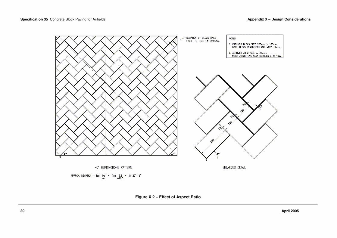
Specification 35 Concrete Block Paving for Airfields Appendix X – Design Considerations
30 April 2005
Figure X.2 – Effect of Aspect Ratio

Specification 35 Concrete Block Paving for Airfields Appendix X – Design Considerations
April 2005 31
Figure X.3 – 45° Herringbone Pattern – Corner Details

Specification 35 Concrete Block Paving for Airfields Appendix X – Design Considerations
32 April 2005
Figure X.4 – 45° Herringbone Pattern – Edge Details at Perimeter

Specification 35 Concrete Block Paving for Airfields Appendix X – Design Considerations
April 2005 33
Figure X.5 – 90° Herringbone Pattern – Edge Details at Perimeter
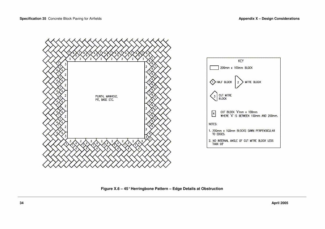
Specification 35 Concrete Block Paving for Airfields Appendix X – Design Considerations
34 April 2005
Figure X.6 – 45° Herringbone Pattern – Edge Details at Obstruction

Specification 35 Concrete Block Paving for Airfields Appendix X – Design Considerations
April 2005 35
Figure X.7 – 90° Herringbone Pattern – Edge Details at Obstruction

Specification 35 Concrete Block Paving for Airfields Appendix X – Design Considerations
36 April 2005
Figure X.8 – Edge Details at Angled Obstruction

Specification 35 Concrete Block Paving for Airfields Appendix X – Design Considerations
April 2005 37
Figure X.9 – Edge Restraint Adjacent to Soft Areas (PCC Kerb)

Specification 35 Concrete Block Paving for Airfields Appendix X – Design Considerations
38 April 2005
Figure X.10 – Edge Restraint Adjacent to Asphalt Pavements (PCC Kerb)

Specification 35 Concrete Block Paving for Airfields Appendix X – Design Considerations
April 2005 39
Figure X.11 – Edge Restraint Incorporating an Expansion Joint
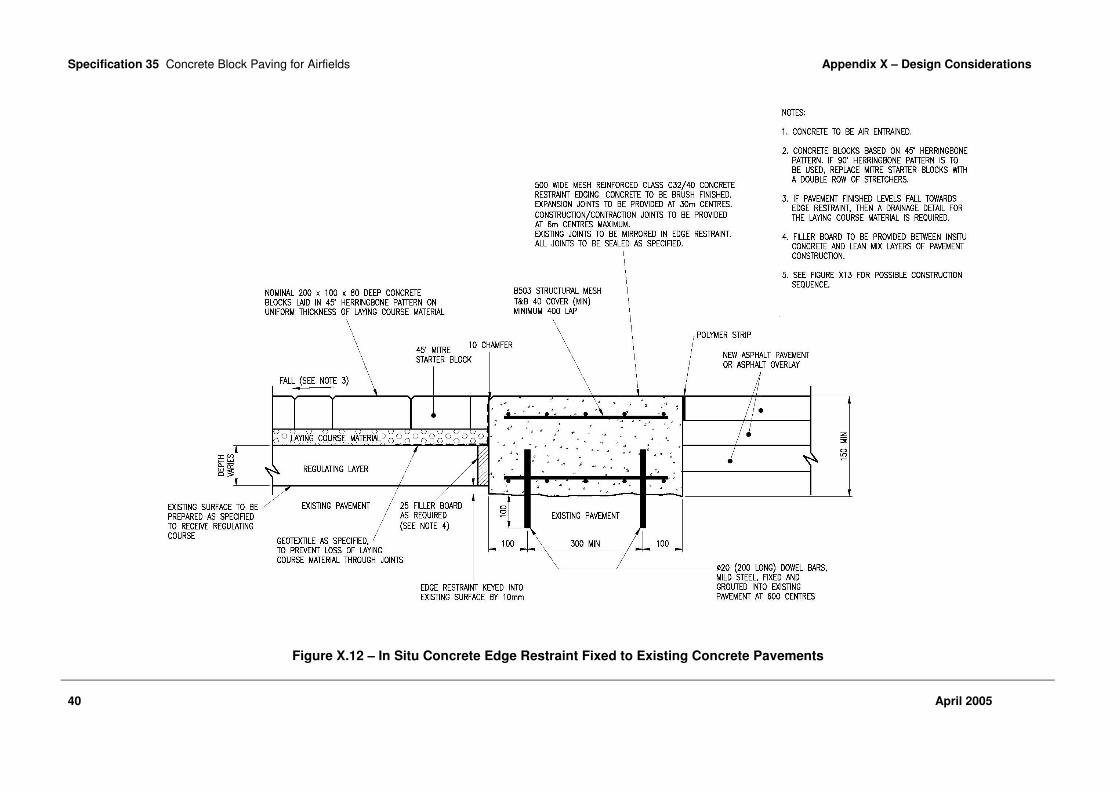
Specification 35 Concrete Block Paving for Airfields Appendix X – Design Considerations
40 April 2005
Figure X.12 – In Situ Concrete Edge Restraint Fixed to Existing Concrete Pavements

Specification 35 Concrete Block Paving for Airfields Appendix X – Design Considerations
April 2005 41
Figure X.13 – Possible Construction Sequence for Figure X.12

Specification 35 Concrete Block Paving for Airfields Appendix X – Design Considerations
42 April 2005
Figure X.14 – Detail at Junction with Continuous Slot Joint Showing Drainage of Laying Course Material

Specification 35 Concrete Block Paving for Airfields Appendix Y – Guidance Notes on Quality Systems for Project Managers
April 2005 43
Appendix Y – Guidance Notes on Quality Systems for Project Managers
Y.1 INTRODUCTION
These Guidance Notes are intended to assist Project Managers in assessing Suppliers’ Quality Assurance (QA) systems for the supply of component and mixed materials as required by Clause 2.4. In particular, guidance is given on:
• how to appraise and evaluate different Quality Systems offered by Suppliers when tendering for jobs (Clauses Y.5 and Y.6); and
• how to monitor work undertaken (Clause Y.7). Separate clauses are devoted to each aspect.
Y.2 GENERAL
Y.2.1 These Guidance Notes are not intended to replace the BS EN ISO 9000 series and associated documentation.
Y.2.2 The generic term “Client” or “Purchaser” in these Guidance Notes is to include the person or organisation that is acting for, or on behalf of, the Property Manager or the Project Sponsor in the role of either a Project Manager or a Works Services Manager.
Y.2.3 The generic term “Supplier” is used to cover any person or organisation that has, or is tendering for, a Contract with the Client to supply a product or service, and includes those traditionally referred to as the (main) Contractor.
Y.2.4 Products which are specified by means of a Harmonised European Standard under the Construction Products Directive are subject to CE marking. It is not permitted to require additional quality assurance or testing requirements over and above those required for Attestation of Conformity within the European Standard. The CE mark certificate should be taken as sufficient evidence of product conformity.
Y.3 QUALITY SYSTEMS
Y.3.1 It is now the accepted practice that all suppliers of goods and services should:
• install and maintain a Quality Management System; and
• become registered to a National Accreditation Council for Certification Bodies (NACCB) accredited third party certification scheme as a Supplier of assessed capability.
Y.3.2 It is general practice that, once a Quality Management Scheme has been set up within an organisation, application for registration to a second or third party certification scheme will be made.
Y.3.3 Second party assessment is carried out by the purchasing organisation; this is very expensive because the resource requirements for systematic and continuous auditing and the management of an assessment scheme are extremely high. Consequently, this form of registration is now in decline and organisations which previously carried out second party assessment, such as British Telecom, British Gas, what used to be the National Coal Board and the MoD, are beginning to insist that their suppliers obtain third party assessment and, hence, pay the costs of quality assurance.
Y.3.4 Certification of a Supplier’s Quality Management System by a third party should provide the Purchaser with the confidence that the Supplier is:
• operating and maintaining a fully documented Quality Management System that addresses consistent requirements; and
• operating within the scope of registration. This avoids the need for the Purchaser to undertake his own structured regime of second party assessments to ascertain the adequacy and focus of the Supplier’s Quality Management Systems.
Y.3.5 However, this does not absolve the Project Manager of his responsibilities on behalf of the Client to ensure that the Quality System of the Supplier addresses all the requirements. This is
Specification 35 Concrete Block Paving for Airfields Appendix Y – Guidance Notes on Quality Systems
for Project Managers
44 April 2005
because the Quality Standards are interpreted differently by individual organisations.
Y.3.6 In principal, the more independent the assessment and audit regime, the more confident the Purchaser can be as to the value of a Supplier’s Quality Management System. Once registered under a certifying body’s scheme, there is still a need to audit, by both the Supplier and the third party certification body, that procedures and standards are being maintained.
Y.3.7 Assessments and audits can be carried out by:
• the Supplier’s management - Under his own audit and monitoring regime;
• the Client (Project Manager) - Second party assessment scheme; or
• an independent body - Third party assessment scheme.
Y.4 PROCESSES COVERED UNDER THE QUALITY SYSTEM
Y.4.1 For a Quality Management System to be effective, it must cover all the operations and processes that are relevant to the business conducted by the Supplier.
Y.4.2 Dependent upon the type of work being tendered for, but as a minimum for the purpose of this Standard, the following areas should normally be addressed:
• procurement, inspection and safe storage of constituent materials;
• training of plant operatives;
• mixing of concrete and concrete blocks;
• inspection and test regimes and records at appropriate stages;
• sub-contractor/supplier assessment and control;
• calibration of equipment; and
• statistical techniques to be used for trend analysis, statistical process control and inspection.
Y.4.3 Quality Management Systems should include provisions for planned and systematic audits, inspections and tests by participating organisations. The Project Manager has the responsibility to evaluate and audit the system being operated by the Supplier to ensure adequacy. This should include checking records to substantiate that the procedures are being followed and that the Supplier has evidence that the materials and works are conforming to the specified standard.
Y.4.4 A Quality Plan in accordance with Defence Standard 05-67 should be stipulated in the Contract as a deliverable, but may be included in the Invitation to Tender if required. The activities described within the Quality Plan shall be stated unambiguously and concisely so that their intent is clear and that, upon implementation, they can be conducted, assessed, audited, demonstrated, measured or verified.
Y.4.5 The Quality Plan must state or contain definitions as to the levels of quality assurance and control to be applied throughout the Contract, which should include:
• traceability of materials;
• frequency and stages of inspections and tests;
• process controls; and
• records (including the retention periods and reviews).
Y.4.6 As quality standards are not extensively defined in relation to the process control, it is the responsibility of the Project Manager to ensure that all processes and methods proposed in Quality Plans are clearly defined and understood with regard to how the Supplier will deal with these aspects of the operation, and that all anomalies, shortfalls, errors and omissions are documented and resolved.
Y.5 ASSESSMENT OF QUALITY MANAGEMENT SYSTEMS
Y.5.1 The assessment of Quality Management Systems is a logical and progressive multi-stage process that encompasses good management precepts.
Y.5.2 A list and records should be maintained of acceptable suppliers and only suppliers on this list should be chosen. Therefore, any solicited or unsolicited suppliers should, as the first stage in the selection process, be required to complete a supplier questionnaire and must, as a minimum, include the following elements:
• verification/proof that the Supplier’s Quality Management System is registered by a Certification Body accredited by NACCB;
• that the registration certificate is current;
• that the offices/sites from which the works or services are to be provided are covered by the registration certificate;
• that the scope of registration is appropriate for the works/services to be provided;
• experience or references of other users of the Supplier’s services;

Specification 35 Concrete Block Paving for Airfields Appendix Y – Guidance Notes on Quality Systems
for Project Managers
April 2005 45
• the Supplier’s past performance, covering experience and results with similar work/projects;
• financial information;
• insurance information; and
• Health and Safety information.
Y.5.3 If the responses to the above are satisfactory, an assessment of the Supplier’s Quality System can be undertaken.
Y.5.4 The extent of the assessment can range from a visit to the Supplier’s premises to overview the Quality Management System in operation on a similar project, to a full formal audit conducted against the BS EN ISO 9000 series and in accordance with BS EN ISO 19011 by the Project Manager’s own QA staff.
Y.5.5 It is the responsibility of the Project Manager to decide if an assessment is necessary. The decision for, and the scope of, such an assessment should be taken on the basis of the size, complexity, cost and length/duration of the Contract in conjunction with the level of confidence that can be established from other sources.
Y.6 ASPECTS TO ASSESS TENDER ACCEPTABILITY
Y.6.1 The requirements for the purchasing of goods and services should, as a minimum, be those set down in the BS EN ISO 9000 series. In order to ensure successful procurement, it is a prerequisite that the purchaser (the Project Manager) provides a clear definition of requirements in the form of contractual conditions and specifications. This aspect applies equally to Quality Management System requirements.
Y.6.2 All Invitations to Tender must contain elements outlining the quality requirements. These should be in the form of asking tenderers to provide:
• proof of registration to the pertinent part of the BS EN ISO 9000 series with an appropriate scope of registration for that particular Contract;
• method statements for all processes to be carried out;
• inspection/test schedules; and
• other information relevant to the Contract.
Y.6.3 When the Supplier returns a tender, his submission must be scrutinised to assess whether his Quality Management System covers all the areas that are relevant to the processes necessary for him to carry out in order that the work is to the
required standard. Where only part of the required elements is covered in the Quality Management System, it may be acceptable for the tenderer to address these areas in his Quality Plan and to compile site-specific procedures for unique elements of the Contract.
Y.6.4 The returned tenders must provide precise details against the information requested in the Invitation to Tender, which is to include the following:
• the Quality System that will be enforced throughout the duration of the Contract;
• the method and procedures to be used to ensure the positive identification and issue status of specifications, drawings, inspection instructions and other data including the requirements for the approval of operational procedures, equipment, staff, operative training and outputs;
• the method and procedures to be used to ensure the conformance to the Specification by processes, inspection and test criteria; and
• methods for the procurement of raw materials, services, etc.
Y.6.5 It is the responsibility of the Project Manager to select those suppliers that they consider will provide the level of confidence that they require to meet the Specification and fulfil their obligations under the Contract.
Y.6.6 Information, in the form of Inspection Records, Test Certificates and Certificates of Conformity, from the Supplier will not normally be supplied automatically unless particularly requested or a contractual requirement. To make sure that the Supplier understands these requirements, a Quality Plan can be required as part of the tender response. The Quality Plan must be evaluated as part of the tender selection process.
Y.6.7 Where the Supplier proposes that some of the work is carried out by sub-contractors, it does not absolve the Supplier of any of his responsibilities to ensure that the work is carried out to the contracted specification and quality.
Y.6.8 The Supplier is to ensure that, where sub-contractors have their own Quality Management System, it is found by scrutiny to be acceptable and they work to it. Where a sub-contractor does not have his own Quality Management System, the Supplier is to impose his own on the sub-contractor. The Project Manager has a responsibility to audit both the Supplier and any sub-contractors to ensure compliance to the tender proposal.

Specification 35 Concrete Block Paving for Airfields Appendix Y – Guidance Notes on Quality Systems
for Project Managers
46 April 2005
Y.7 MONITORING THE QUALITY MANAGEMENT SYSTEM AND PROCESSES
Y.7.1 Whilst the Supplier may have registration to the BS EN ISO 9000 series, it does not necessarily mean that his system is fully focused on the specific requirements of the Contract, nor does any second party scheme run by another purchaser. Monitoring of the system should take place irrespective of whether the Supplier has, or has not, achieved registration.
Y.7.2 The Supplier should have procedures in place for the auditing, monitoring, recording and rectifying of all his activities. The Project Manager should ensure, by conducting surveillance audits of the Supplier’s system, that:
• these are being carried out;
• the system is effective; and
• the system is focused on the Contract requirements and deliverables.
Y.7.3 Within the Contract, there are requirements for the Supplier to carry out tests on the materials, etc. The Supplier may not have his own test laboratory, in which case he will send samples out to a test house. Any test laboratory, whether part of the Supplier’s organisation or an independent test house, conducting the tests for initial approval of materials and design of mixtures should be a National Measurement Accreditation System (NAMAS) accredited test house with an appropriate test schedule. Site laboratories used to carry out routine tests on bulk supplies and mixtures throughout plant mixing shall be either NAMAS accredited or, subject to the Project Manager’s approval, work to a Quality Assurance scheme.
Y.7.4 Where non-compliances are found, whether within the system being operated or the goods or services provided, they can be either random instances when the value is outside the specified range or an indication of a trend. If the running mean of the last, say, twenty results has remained reasonably consistent with a standard deviation that also has not fluctuated, then it is likely to be a random instance. Preferably, the running means and standard deviations should be monitored to allow corrective action before non-compliancies occur. All actions taken to deal with non-compliancies are to be documented.
Y.7.5 Rates of sampling and testing must be appropriate to the Contract and stated clearly in the Quality Plan. Where rates are stipulated in the Contract (see Section 8), these will take preference.
Y.7.6 The procedures for sampling and testing concrete blocks and their constituents are to be in accordance with the appropriate parts of the latest editions of relevant British Standards, and also with the latest edition of the appropriate Appendices to this Standard. All samples and testing should be carried out by suitably trained personnel. The results are to be supported by valid Test or Sample Certificates.
Y.7.7 The use of a Quality System should minimise the need for the Project Manager to carry out his own tests. Therefore, they can:
• do nothing because the Supplier is carrying out sufficient inspections and tests, and assessing the results and implications;
• assess the Inspection and Test Results for the material provided for the Contract to ensure that checks are being made and that the results indicate compliance to the Contract and Quality Plan is being achieved; or
• conduct a separate inspection and test regime of his own to check for compliance.
Y.8 RECORDS
Y.8.1 The training records of all operatives, sampling and testing personnel are to be maintained by the Supplier and are to be made available for inspection.
Y.8.2 The results of all inspections, tests, etc. for the Contract should be obtained and retained for record purposes. All documentation (including work-sheets, Inspection and Test Certificates and Certificates of Conformity) that are relevant to the Contract should be:
• available at the place of work (usually the plant or depot) for inspection by the Project Manager for the duration of the Contract; and
• handed over to the Project Manager on completion of the Contract.

Specification 35 Concrete Block Paving for Airfields Appendix Z – Guidance Notes on the Preparation of Job Specifications
April 2005 47
Appendix Z – Guidance Notes on the Preparation of Job Specifications
Z.1 CONCRETE BLOCKS – GENERAL
Z.1.1 To safeguard against Foreign Object Damage (FOD) to aircraft the concrete blocks must be hard wearing and durable and not susceptible to premature surface weathering/decay or edge spalling or cracking. Also, the blocks should not contain sharp edges which could endanger or cause excessive wear to aircraft tyres. A significant factor in this respect, notwithstanding the test requirements at Section 8, is the standard of finish to blocks. Experience of block paving work on MOD airfields has shown that it can vary between block paving manufacturers and also within the same production from one manufacturer. Hence, the importance of the requirements of Clause 3.1.3 in the initial approval of blocks for the Project.
Z.1.2 For the sample of blocks to be acceptable under Clause 3.1.3, apart from colour and shape/dimensional considerations, the surface finish should be consistent and free of defects as described; some guidance on the procedure for verification is given in BS EN 1338. The blocks must not contain any weakly bound aggregate particles or voids in the upper/wearing face such that concentrated loads may break or chip the surface. Also, in respect of durability and surface weathering, the blocks should have a consistent and closed surface texture on the upper/wearing face.
Z.1.3 In the course of giving initial approval of blocks as required under Clause 3.1.2, it is important that the Contractor and his Supplier/Manufacturer are made aware that notwithstanding test criteria at Section 8, the standard of finish of all blocks to be supplied for the Project must comply with that approved for the sample blocks.
Z.2 CONCRETE BLOCKS - COARSE AGGREGATE
Z.2.1 The preferred choice of aggregate is crushed rock. This preference is based on experience of performance of Pavement Quality Concrete (PQC) pavements at MOD airfields constructed using both gravel and crushed rock coarse aggregates. The main points are as follows:
• Gravels may contain a proportion of unsuitable particles randomly distributed throughout their bulk which is too small to be detected in approval tests but is large enough to precipitate a surface failure. At a crushed rock source, unsuitable material can usually be detected during inspection of the quarry faces and avoided.
• Gravels and especially flint gravels which occur widely over the south of England have a high coefficient of thermal expansion. Hence, blocks made with these aggregates and then laid tightly together with minimum joint spacings and in large areas are much more likely to induce critical expansion forces in the paving in hot weather. See also Clause X.6.2 in Appendix X.
Z.2.2 Concrete block manufacturers in the UK mostly use gravel coarse aggregates (at the time of writing). Hence, restricting aggregates to crushed rock only could result in a significant cost penalty being incurred on a project. The Project Manager will, therefore, need to take account of this in a value engineering assessment at the planning/design stage of a project.
Z.3 LAYING COURSE MATERIAL
Z.3.1 A critical factor in the performance of concrete block paving is the stability and durability of the laying course material. These properties in turn are affected by the grading of the material, the degree of compaction and variation in thickness of the layer and the resistance of the material to abrasion and degradation under the action of trafficking and weathering.

Specification 35 Concrete Block Paving for Airfields Appendix Z – Guidance Notes on the Preparation of Job Specifications
48 April 2005
Requirements in respect of the stability of the laying course material are included in the specification but except for the provision of a clean, sharp, naturally occurring, predominantly silica fine aggregate, definitive test criteria are not included in respect of durability of the material. Experience on MOD airfields is insufficient to validate such a test criteria. Nevertheless, it is recommended that as a quality control measure the following be included at Clause 4.2.3 for pavements subject to "Medium Frequency Usage" and above (i.e. as defined in "A Guide to Airfield Pavement Design and Evaluation" – PSA 1989), when aircraft tyre pressures are in excess of 0.7 MN/m² (100 psi) and also for pavements on which aircraft are to be parked with tyre pressures in excess of 0.7 MN/m² (100 psi). The Contractor shall submit test data as evidence to the Project Manager that the material proposed for use in the Project has satisfactory durability properties. For this purpose submission of test data showing compliance with one of the following will suffice:
• The maximum Magnesium Sulphate Soundness Value of the material when tested in accordance with the procedure at Appendix A shall be 25 % or
• The material shall be tested for degradation using the principle of the Micro Deval Test (BS EN 1097-1). From a sample taken from the grading test at clause 8.3.1, three sub-samples of 0.2 kg shall be remixed and each placed in a nominal one litre capacity porcelain jar together with two 25 mm diameter steel ball bearings weighing (75 ± 5) grams each. The jar shall be rotated at 5 rpm for six hours. The sieve analysis shall then be repeated and the average of the three sub-samples taken and compared with the results of the grading tests at clause 8.3.1. The maximum allowable increase in the percentage passing each sieve and the maximum percent passing shall be as given in Table Z.1.
TABLE Z.1 MAXIMUM ALLOWABLE INCREASE PASSING EACH SIEVE SIZE
BS sieve Maximum allowable increase
in percentage passing
Maximum allowable
percentage passing
0.250 mm 5 32
0.125 mm 5 11
0.063 mm 2 2
Z.4 EDGE AND INTERMEDIATE RESTRAINTS
Z.4.1 A specification which could be utilised for in situ concrete edge/intermediate restraints is contained in Section 7 of DE Specification "Pavement Quality Concrete for Airfields".
Z.4.2 Advice on typical details for edge/intermediate restraints is given in Appendix X.
Z.5 REGULATION OF EXISTING SURFACES
The stability of the top 100 mm – 150 mm of base/regulating material beneath the concrete block paving can be particularly critical dependent on frequency and nature of aircraft usage. For blacktop regulating the most onerous case is likely to be a parking area for heavy, high tyre pressure aircraft because of the potential for rutting, indentation and general loss of surface shape as a result of load intensity and effect of creep. Further guidance, including specification requirements, is given in Appendix X.
Z.6 REDUCTION OF EXISTING SURFACES
Specification Clauses for reduction in surface level of bituminous surfaces and reduction in level of concrete surfaces, which could be utilised in Clause 6.6, are contained in Section 5 of DE Function Standard "Marshall Asphalt for Airfields".
Z.7 PREPARATION OF EXISTING SURFACES
Z.7.1 Specification Clauses for preparation of existing bituminous and concrete surfaces and filling ravelled lane joints and potholes etc which could be utilised in Clause 6.7 are contained in Section 5 of DE Specification "Marshall Asphalt for Airfields".
Z.7.2 In addition to relevant clauses from the DE Marshall Asphalt Standard it is recommended that the following be incorporated in Clause 6.7:
• Joints or cracks in existing pavements are to be masked with an approved strip/geotextile, fastened in position with an approved adhesive (i.e. to prevent loss of laying course material - refer also to Appendix X).

Specification 35 Concrete Block Paving for Airfields Appendix Z - Guidance Notes on the Preparation of Job Specifications
April 2005 49
• Immediately prior to applying the laying course material as specified in Clause 6.8, the existing surface shall be clean, smooth and free of excess moisture, mud, grit and other extraneous matter.

Specification 35 Concrete Block Paving for Airfields References
50 April 2005
References
Defence Estates, Ministry of Defence
FS 06 1994 Functional Standard 06, Guide to Maintenance of Airfield Pavements
SPEC 12 2005 Specification 12, Hot Rolled Asphalt and Macadam for Airfields SPEC 13 2005 Specification 13, Marshall Asphalt for Airfields SPEC 33 2005 Specification 33, Pavement Quality Concrete for Airfields SPEC 40 2005 Specification 40, Porous Friction Course for Airfields SPEC 49 2005 Specification 49, Stone Mastic Asphalt for Airfields
DMG 27 2005 Design and Maintenance Guide 27, A Guide to Airfield Pavement Design and Evaluation
Report 1994 RAF Mildenhall Concrete Block Surfacing Trial – FWD Testing – TBV
Consult Report 1994 Development of Technical Standard – Concrete Block Paving for Airfield
Pavements – BAA Report 1995 RAF Brize Norton – Upgrade of SE Quadrant – Trial Areas – SWK
British Standards Institution
BS 21 1985 Specification for pipe threads for tubes and fittings where pressure-tight joints are made on the threads (metric dimensions)
BS 594 Hot rolled asphalt for roads and other paved areas Part 1 2003 Specification for constituent materials and asphalt mixtures BS 2782 Methods of testing plastics. Mechanical properties Part -3 1976 Methods 320A to 320F: Tensile strength, elongation and elastic modulus BS 4987 Coated macadam (asphalt concrete) for roads and other paved areas Part 1 2003 Specification for constituent materials and for mixtures Part 2 2003 Specification for transport, laying and compaction BS 7263 Precast concrete flags, kerbs, channels, edgings and quadrants. Part 3 2001 Precast, unreinforced concrete kerbs, channels, edgings and quadrants.
Requirements and test methods BS 7533 Pavements constructed with clay, natural stone or concrete pavers. Part 3 1997 Code of practice for laying precast concrete paving blocks and clay pavers
for flexible pavements BS EN 196 Methods of testing cement. Part 2 1995 Chemical analysis of cement Part 7 1992 Methods of taking and preparing samples of cement Part 21 1992 Determination of the chloride, carbon dioxide and alkali content of cement BS EN 197 Cement. Part 1 2000 Composition, specifications and conformity criteria for common cements Part 2 2000 Conformity evaluation BS EN 932 Tests for general properties of aggregates. Part 1 1997 Methods for sampling Part 2 1999 Methods for reducing laboratory samples

Specification 35 Concrete Block Paving for Airfields References
April 2005 51
BS EN 933 Tests for geometrical properties of aggregates. Part 1 1997 Determination of particle size distribution. Sieving method Part 2 1996 Determination of particle size distribution. Test sieves, nominal size of
apertures BS EN 1097 Tests for mechanical and physical properties of aggregates. Part 1 1996 Determination of the resistance to wear (micro-Deval) Part 2 1998 Methods for the determination of resistance to fragmentation Part 5 1999 Determination of the water content by drying in a ventilated oven Part 6 2000 Determination of particle density and water absorption BS EN 1338 2003 Concrete paving blocks – Requirements and test methods BS EN 1367 Tests for thermal and weathering properties of aggregates. Part 2 1998 Magnesium sulphate test BS EN 12620 2002 Aggregates for concrete BS EN 13036 Road and airfield surface characteristics – Test methods. Part 1 2002 Measurement of pavement surface macrotexture depth using a volumetric
patch technique BS EN 13043 2002 Aggregates for bituminous mixtures and surface treatments for roads,
airfields and other trafficked areas BS EN ISO 9000 2000 Quality management systems. Fundamentals and vocabulary Part 1 1994 Quality management and quality assurance standards. Guidelines for
selection and use BS EN ISO 9001 2000 Quality management systems. Requirements BS EN ISO 19011 2002 Guidelines for quality and/or environmental management systems auditing BS ISO 9000 Quality management and quality assurance standards. Part 2 1997 Generic guidelines for the application of ISO 9001, ISO 9002 and ISO 9003
Her Majesty’s Stationery Office
DS 05-67 1980 Defence Standard 05-67, Guidance to Quality Assurance in Design
Property Services Agency
1989 A guide to airfield pavement design and evaluation Report 1991 The Use of Small Interlocking Concrete Blocks for Aircraft Pavements –
Property Services Agency Report 1991 Concrete Block surfacing – Investigation of Structural Properties – Property
Services Agency
Brick Development Association, Interpave and Interlay
1994 The Construction of Petrol Filling Stations in Clay or Concrete Pavers – A Code of Practice for Design, Detailing and Construction

Specification 35 Concrete Block Paving for Airfields References
52 April 2005
British Ports Association
1983 The Structural Design of Heavy Duty Pavements for Ports and Other Industries
International Civil Aviation Organization (Quebec)
Annex 14 International Standards and Recommended Practices, Aerodromes: Annex 14 to the Convention on International Civil Aviation
Volume 1 1990 Aerodrome design and operations 9137 Part 2 Airport Services Manual
US Federal Aviation Administration
I5O/5320-6 Airport Pavement Design and Evaluation (Advisory Circular) Item P-502 Standards for Specifying Construction of Airports – Interlocking Concrete
Paver Block Construction for Airport Pavement