concentrator/headspace analysis injector · concentrator/headspace analysis injector ... remove the...
TRANSCRIPT
CONCENTRATOR/HEADSPACEANALYSIS INJECTOR
Installation and operation Instructionsfor kit Manual Control when used with Control Module
SGE International, 7 Argent Place, Ringwood, 3134, Australia
SGE International Pty. Ltd.Toll Free: 1800 800 167Tel: +61 (0) 3 9837 4200Fax: +61 (0) 3 9874 5672Email: [email protected]
SGE, Incorporated (USA)Toll Free: (800) 945 6154Tel: (800) 945 6154Fax: (512) 836 9159Email: [email protected]
SGE Europe Ltd.Tel: +44 (0) 1908 568 844Fax: +44(0) 1908 566 790Email: [email protected]
SGE (France) SarlTel: (0) 1 43 82 29 43Fax: (0) 1 43 82 42 68Email: [email protected]
SGE Italia Srl.Tel: 06 4429 0206Fax: 06 4429 0724Email: [email protected]
SGE Deutschland GmbHTel: +49 (0) 6151 860486Fax: +49 (0) 6151 860489Email: [email protected]
SGE Japan Inc.Tel: +81 45 222 2885Fax: +81 45 222 2887Email: [email protected]
SGE IndiaTel: +91 (022) 471 5896Fax: +91 (022) 471 6592Email: [email protected]
SGE China Tel: +86 (10) 6588 1666Fax: +86 (10) 6588 2917
Publication No. MN-0133-A Rev 01
w w w. s g e . c o m

WARRANTY STATEMENT
This CHIS and Control Module is guaranteed against faults in materials or workmanship for a period of twelve months from the date of invoice.
This warranty implies free repair and or replacement of defective goods only,upon proper written proof and, where authorised, return of the defectiveproduct.It does not cover 'disposables'.
THIS UNIT HAS BEEN DESIGNED TO FULFIL THE PURPOSE OF CONCENTRATED/HEADSPACE INJECTION AND THIS WARRANTY IS VOID IF THE INSTRUMENT IS USED FOR ANY UNRELATED PURPOSE. SGE RESERVESTHE RIGHT TO REFUSE FREE SERVICE UNDER WARRANTY ON ANY UNIT WHICHHAS BEEN ABUSED OR TAMPERED WITH IN ANY WAY.
No other warranty or representation is expressed or implied by SGE for its products with respect to merchantability and fitness for any particular use or purpose or any other matter. SGE shall not under any circumstances, be liablefor any incidental, consequential, or compensatory damages arising from useof or in conjunction with its products. The maximum liability for breach ofwarranty shall be the invoice price of said products.
SGE acknowledges that there are many service engineers in the field who havethe expertise to service the CHIS or Control Module and to assist them wehave enclosed the necessary data in this manual.
To protect your interest, however, we respectfully suggest that any failuresduring the warranty period be attended to by SGE service personnel or by SGE authorised service people.
TABLE OF CONTENTS
1.0 Introduction
2.0 Kit Instructions, Carrier Gas Connections
3.0 The Control Module
4.0 Control Module Installation Instructions
5.0 Function and Operation of the CHIS Injector
6.0 Appendix 1
7.0 Parts List

1.0 INTRODUCTIONThe Concentrator/Headspace injector is a dedicated, capillary gas chromatography sample introduction system, designed for use with a wide range of air or aqueous samples.
Samples are drawn through the glass lined absorption tube packed with an adsorbent. Organic materials are trapped in the absorption tube, enabling trans-fer to the gas chromatograph.
The absorption tube is inserted into the special injector located in the heated injection block of the gas chromatograph. In "desorb" mode the sample components are thermally desorbed from the absorption tube and focused at thehead of the capillary column.
As the sample is chromatographed in "run" mode, a reverse flow of carrier gas tovent, cleans and conditions the absorption tube ready for the next sample.
SYSTEM REQUIREMENTS
The CHIS injector must be installed into a spare injection block position in the gaschromatograph. This may require the removal of an existing injector, or the injection block (HP5890), to make room for the CHIS. Removal and replacement ofinjectors is a simple procedure and should be done when the injector is cool.
A 1/16” carrier gas line is required for connection with the CHIS system.This line must originate after the carrier gas pressure regulator.
ABSORPTION TUBES
The absorption tubes supplied with the CHIS Injection System are packed withTenax™ TA, 60/80 mesh. Tenax is suitable for adsorbing compounds >C6 and C1 to C5depending on functional group. The tubes can be emptied and repacked with other adsorbents if required. Appendix 1 lists some of the more common adsor-bents and the application specifications.
INSTALLATION OF INJECTOR ASSEMBLY
1. Remove the existing injector components from the injector heater block.If necessary refer to the instrument maintenance manual for information on injector removal procedure.
NOTE: In the case of the HP5890, (or gas chromatographs which require the CHISA 50kit), the existing heater block should be removed to enable installation
1

1
2
3
4
5
7
8
12
13
9
10
11
6
Figure 1.
1514
of the SGE heater block supplied .(Refer to Section 18 of the Hewlett Packardmaintenance manual (Series I & II) for anexploded diagram of the heater block) theHeater Cartridge and Thermocouple should bereinstalled.
2. Locate and install the Instrument Specific brass Adaptor (6) in the instrumentheater block.
3. Install the "screw threaded” InjectorBody (5) through the top of the InstrumentSpecific Adaptor. The screw threaded endof the Injector Body should now be locatedin the gas chromatograph oven.
4. The CHIS injector is supplied with thepneumatic inlet Tee unions (10, 11, 12 & 13)assembled.(If re-fitting of these components is required, assemble the GLT interface tube(11), Vespel Sealing Ring (12) and Tee (13)onto the Union Tee (10) as shown in figure1.(Note: the square end of the GLT interfacetube is located into the Union Tee (10).
5. Install a Graphitised Vespel Tube Seat (9)into the Union Tee (10) as shown ensuringthe Seat locates into the positioning well atthe base of the Tee.
6. Fit and finger tighten the SSN/4 Nut (7)onto the Union Tee (10) with the GVF/4 fer-rule (8) located as shown figure 1 (Taperup).
7. Locate and screw assembly UnionTee (10)onto the CHIS Body (5) until finger tight.
8. Spanner tighten the SSN/4 Nut (7) toobtain a leak tight seal with the CHIS body.
2
Additional Spares
Description Used In Part No.
0.8mm ID empty absorption tube for CHISA CHISA 0932230
3.0mm ID empty absorption tube for CHISA CHISA 0932232
0.8mm ID empty absorption tube for CHISB CHISB 0932234
3.0mm ID empty absorption tube for CHISB CHISB 0932236
Additional Accessories
Description Code Part No.
CHIS A- Storage tube 0932260
CHIS B - Storage Tube 0932261
CHIS tube conditioning module 0932262
Detector connector kit for 1/4" fittings DC-4 103462
Detector connector kit for 1/8" fittings DC-8 103463
Detector connector kit for 5mm fittings DC-05 103464
Detector connector kit for Varian 3700
and later GC models DC-4V 103465
Detector connector kit for HP5890 DC-4HP5890 103467
Constant flow velocity connector Varian DRC-Varian 1034681
Constant flow velocity connector HP DRC-HP 1034683
CO2 Cryogenic focusing system CTS.LCO2 093346
Trademarks
Tenax™Enka Research Institute
Carboxen™Supelco Inc.
Carbosieve™Supelco Inc.13
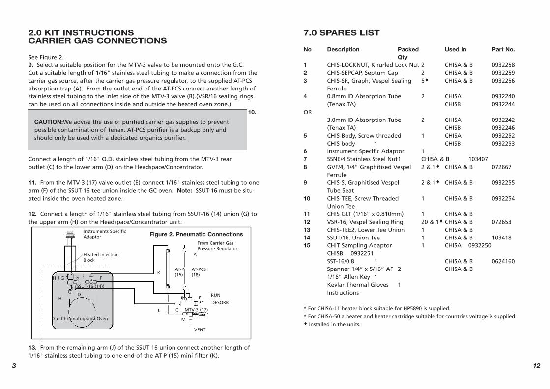
2.0 KIT INSTRUCTIONS CARRIER GAS CONNECTIONS
See Figure 2.9. Select a suitable position for the MTV-3 valve to be mounted onto the G.C.Cut a suitable length of 1/16" stainless steel tubing to make a connection from thecarrier gas source, after the carrier gas pressure regulator, to the supplied AT-PCSabsorption trap (A). From the outlet end of the AT-PCS connect another length ofstainless steel tubing to the inlet side of the MTV-3 valve (B).(VSR/16 sealing ringscan be used on all connections inside and outside the heated oven zone.)
10.
Connect a length of 1/16" O.D. stainless steel tubing from the MTV-3 rear outlet (C) to the lower arm (D) on the Headspace/Concentrator.
11. From the MTV-3 (17) valve outlet (E) connect 1/16" stainless steel tubing to onearm (F) of the SSUT-16 tee union inside the GC oven. Note: SSUT-16 must be situ-ated inside the oven heated zone.
12. Connect a length of 1/16" stainless steel tubing from SSUT-16 (14) union (G) tothe upper arm (H) on the Headspace/Concentrator unit.
13. From the remaining arm (J) of the SSUT-16 union connect another length of1/16" stainless steel tubing to one end of the AT-P (15) mini filter (K).
3
Figure 2. Pneumatic ConnectionsInstruments SpecificAdaptor
Heated InjectionBlock
Gas Chromatograph Oven
(SSUT-16 (14))
FG
H
JH J G F
D
K
B
L
A
AT-P(15)
E
C
M
VENT
RUN
MTV-3 (17)
DESORB
AT-PCS(18)
From Carrier GasPressure Regulator
CAUTION:We advise the use of purified carrier gas supplies to prevent possible contamination of Tenax. AT-PCS purifier is a backup only andshould only be used with a dedicated organics purifier.
7.0 SPARES LIST
No Description Packed Used In Part No.Qty
1 CHIS-LOCKNUT, Knurled Lock Nut 2 CHISA & B 09322582 CHIS-SEPCAP, Septum Cap 2 CHISA & B 09322593 CHIS-SR, Graph, Vespel Sealing 5♦ CHISA & B 0932256
Ferrule4 0.8mm ID Absorption Tube 2 CHISA 0932240
(Tenax TA) CHISB 0932244OR
3.0mm ID Absorption Tube 2 CHISA 0932242(Tenax TA) CHISB 0932246
5 CHIS-Body, Screw threaded 1 CHISA 0932252CHIS body 1 CHISB 0932253
6 Instrument Specific Adaptor 17 SSNE/4 Stainless Steel Nut1 CHISA & B 1034078 GVF/4, 1/4” Graphitised Vespel 2 & 1♦ CHISA & B 072667
Ferrule9 CHIS-S, Graphitised Vespel 2 & 1♦ CHISA & B 0932255
Tube Seat10 CHIS-TEE, Screw Threaded 1 CHISA & B 0932254
Union Tee11 CHIS GLT (1/16” x 0.810mm) 1 CHISA & B12 VSR-16, Vespel Sealing Ring 20 & 1♦ CHISA & B 07265313 CHIS-TEE2, Lower Tee Union 1 CHISA & B14 SSUT/16, Union Tee 1 CHISA & B 10341815 CHIT Sampling Adaptor 1 CHISA 0932250
CHISB 0932251SST-16/0.8 1 CHISA & B 0624160Spanner 1/4” x 5/16” AF 2 CHISA & B1/16” Allen Key 1Kevlar Thermal Gloves 1Instructions
* For CHISA-11 heater block suitable for HP5890 is supplied.
* For CHISA-50 a heater and heater cartridge suitable for countries voltage is supplied.♦ Installed in the units.
12

14. Connect a further 1/16" stainless steel line between the AT-P (15) (L) and the BMCV-1 (16) (M).
15. Connect the capillary column into the tee union (D) using the suppliedSSNE16-012 nut (15) Fig. 1. It is important to insert the column so that it terminates just into the vespel seat (9). The distance from the bottom of thetee union (13) to the seat is approximately 24mm.
3.0 THE CONTROL MODULE
INTRODUCTION
This control module is designed to provide all the pneumatic controls to allow conversion of your gas chromatograph to perform capillary column analysis ofsamples obtained by absorption into the sample tube of the SGE Concentrated Headspace Injection System, here in referred to as CHIS.
A. FRONT PANEL
Purge: Controls the rate of back flush of the sample tube after injection.
Purge Outlet: Allows measurement when required, of the back flush rate.
Cooling Gas: The action of desorbing and backflushing the sample tube alsocleans and conditions it ready to be used for taking a new sample. To preventthe ingress of “contaminated” laboratory air during cooling, the tube isremoved from the injector and immediately inserted in a receptacle within thebody of the control module, which is purged with clean compressed gas. Thisvalve turns on/off the gas as required, during this process.
Run - Desorb: During the insertion and removal of the sample tube, the injec-tor is open to the air and carrier gas must be maintained to the column.During the desorption of the sample the carrier must be redirected down theabsorption tube.This switching valve directs the carrier gas in the appropriate direction asrequired.In the CHIS-2 version of the Control Module this switching valve isreplaced by an electric solenoid valve (see under “Remote” in the descriptionof the Rear Panel).
Carrier Control: This pressure regulator and gauge provides the carrier gascontrol for capillary chromatography.
411
e. After the appropriate “desorption” time as determined by experiment, the module is returned to the “RUN” mode during which time the samplingtube is reconditioned while the chromatography continues.
f. At the end of the chromatographic run, switch on the cooling gas to thecooling receptacle by moving the "Purge Gas " toggle valve to the "on" posi-tion.
g. Remove the sampling tube from the injector and immediately insert it intothe cooling receptacle located in the top of the control module.
h. Insert either the next sample tube or a "blank" tube into the injector tomaintain the column head pressure.
6.0 APPENDIX 1
TRAPPING MATERIAL PROPERTIES
Tenax™ - TA Traps C6 and greater, C1 to C5 depending on functional groups.Does not trap low-boiling solvents and highly volatile compounds.
Carboxen™ - 563 Traps C3 and greater, C1 to C2 depending on functional groups.Halogenated compounds in water.
Molecular Sieve 5A** Traps C3 and greater.
Activated Charcoal Traps C3 and greater, C1 to C2 depending on functional groups.
Carbosieve™ S-111 Traps C2 and greater. Excellent for compounds such as ethane and ether.
NOTE:Tenax TA is particularly useful for the analysis of high boiling compounds such asalcohols, polyethylene glycols, diols, phenols, monoamines, diamines,ethanolamines, aldehydes, ketones and chlorinated aromatics.** The capacity of Molecular Sieves is depressed by the adsorption of CarbonDioxide and water vapour. Condition in excess of 300 °C to remove these.

4.0 CONTROL MODULE INSTALLATION INSTRUCTIONS
CHIS 1 Control Module - Standard Version
1. Position the unit alongside the gas chromatograph.
2. Connect the carrier gas source into the rear of the Control Module.
3. Using a suitable length of 1/16” stainless steel tubing connect the Carrier Out port of the Module to inlet D of the injector. See Figure 2.
4. Similarly connect a second piece of tubing from the “Aux Out” port topoint F
on the tee piece (SSUT-16, # 103418) located inside the oven.
5. Connect point G on the tee piece to point H on the injector using a shortpiece
of stainless steel tubing.
6. Connect point J on the tee piece to “Back Purge In” port on the rear of the module.
7. Connect Make-Up gas of choice into the “Make Up In” port on rear of the control module.
Instrument SpecificAdaptor
HF
(SSUT-16(14)
JG
Heated InjectionBlock
GAS CHROMATOGRAPH OVEN
Figure 4. Pneumatic connections
D
Carrier Out
Aux Out
Back Purge In
Rear ofControlModule
5
Aux In
Allows introduction of the “cooling gas” (see front panel description).
Aux Out
As outlined in the front panel description under “Run-Desorb”, carrier gasmust be supplied to the injector from two sources to allow switching of thedirection. This is the alternative source to that provided from the “CarrierOut” port.
Cool Out
Not used.
Remote
Provides the electrical connection to the solenoid in the CHIS 2 version.This solenoid, which is driven from a data station or instrument panel control,performs the same function as the toggle valve labelled “Run - Desorb” on the front panel of the manual (CHIS 1) version.
Carrier Out
Allows the injector to be supplied with pressure controlled carrier gas.
Carrier In
Allows input of carrier gas from pressurised cylinders or tanks. NB.This carrier gas should be scrubbed free of oxygen, moisture and organiccontaminants. Ensure line traps are in good condition.
Make Up Out
Allows make-up gas to be supplied to the detector connector of the GC toallow optimisation of the particular detector.
Make Up In
Allows introduction of the appropriate make-up gas from the cylinder or tank.
10

using 1/16” OD stainless steel tubing.NB:VSR 16 sealing rings can be used on all connections both inside and outside
the heated oven zone.
9. Connect the capillary column into the tee union (D) using the SSNE16-012 nut supplied (15) Fig. 1. It is important to insert the column so that it termi-
natesjust into the vespel seat (9). Refer to figure 1. The distance from the bottom of the tee union (13) to the seat is approximately 24mm.
10. Assembly of Absorption Tubes.The CHIS injector is supplied with prepacked Sampling Tubes.If assembly of these tubes is required, follow the procedure below:a) Locate and fit the Vespel Sealing Ferrule (3) taper facing up.b) Fit the Septum Cap (2) and Lock Nut (1)c) Prior to using the Headspace/Concentrator System, check that all connections are secure and no leaks exist.
11. For the CHIS - 2 version of the injector, the 'Run-Desorb' toggle valve on the front panel is not present and is replaced by a solenoid valve which is drivenfrom a data station, or a GC external events function.DC power to the solenoid is supplied via the plug provided. Although the plug will only fit one way, the voltage does not need to be polarised.
NB:Check the rear of the module for the DC Voltage required. Power consump-tion
is 0.65 Watt at the specified voltage.
5.0 FUNCTIONS AND OPERATION OF THE CHIS INJECTOR
The following instructions outline the functions and operation of theConcentrator/Headspace system.
FUNCTIONSHeadspace/Concentrator Operation Modes.
Run ModeAllows a flow directly onto the column with a purge of carrier through the absorp-tion tube to vent.
Desorb ModeThe adsorbed sample is thermally desorbed and carried onto the capillary column.
Figure 5 illustrates the flow path of these two modes. 6
Make-up GasGC detectors, particularly Flame Ionisation Detectors and Electron CaptureDetectors are designed, under optimum conditions, to operate at much higherflows than are used with capillary gas chromatography. This control allows theaddition of gas, after the column, to allow optimisation of the detector bymaking up the gas flow to the design specification. If the chromatograph isnot provided with a make-up gas inlet to the detector, consult the SGE cata-logue for details on our comprehensive range of detector connectors. Partnumbers; 103462 to 103467, 1034681 and 1034683.
B. BACK PANEL
Back Purge In (Septum Purge Port) After desorption, the sampling tube is back purged to clean and condition it for re-use. This port allows control of the purging rate.
Split VentNot used.
Figure 3. CHIS 1 Control Module
SEPTUM PURGE
CARRIER GAS
RESTRICTOR
OUT
AUX OUT
AUX IN
IN
MAKE UP GAS FLOWCONTROLLER
MAKE UP GASOUT
IN
CARRIER GASPRESSURE REG-ULATOR
COLUMNHEAD PRES-SURE
RUN/DESORB
PURGE GASON/OFF
BACK PURGE
PURGE VENT
TRAP
TRA
P
9

OPERATION
1. Conditioning of Absorption Tubes
The four absorption tubes supplied are packed with Tenax TA adsorbent material.Prior to initial use, each absorption tube will require conditioning.
Conditioning of the absorption tubes should be done in the injector at 300°C fortwo to three hours with the headspace/concentrator in RUN mode. A vent flowout of the purge outlet 10-25ml/min. is recommended. During this procedure acolumn should be installed in the gas chromatograph, or a piece of fused silica orstainless steel plumbing between the injector and detector, to prevent build up ofcarrier gas inside the oven especially when Hydrogen is being used.
As an alternative to conditioning tubes on a "one-off" basis, the SGE CHIS TubeConditioning Module allows for six tubes to be prepared simultaneously withoutusing the injector at all. (Part number 0932260 CHIS Tube Conditioning Module).
2. Vent Flow Setting for Operational Modes
A vent flow of 10-25ml/min is recommended during standard operation of the CHIS.
3. Sample Collection
Sample collection into the absorption tube maybe performed two ways:a. By connecting the absorption tube to a vacu-um source using the sample adaptor.ORb. By pushing the sample through the absorptiontube. The tube is connected into the adaptor asper Figure 6.
4. Desorbing the Sample(Refer Fig. 1).
Once a sample has been adsorbed into an absorption tube, chromatography of the adsorbedcomponents is carried out as follows:
a. Set injection port temperature and wait for it to stabilise.
b. Ensure that CHIS is switched to the “RUN”position using the toggle valve or solenoid.
c. Insert the absorption tube into the main body(5) complete with cap (2) and lock nut (1) assem-bly and secure so that the tube is sealed.
d. The valve is then switched into DESORB mode for the time needed to des-orb the sample. (Experiments should be performed to determine required des-orption times. Begin with 2 minutes and vary the times both longer and short-er).
NOTE: The use of Cryogenic focusing is recommended for applications involvingvolatile samples. Using this method reduces peak tailing and band broadening dueto the sample not being deposited in a narrow band at the beginning of the col-umn.
SGE’s cryogenic focusing system (optional) (CTS.LCO2 Part Number 093346) isrecommended for this purpose.
Figure 6. Sampling Adaptor
Back PurgeValve
Back PurgeValve
AdsorptionTrap
Run - DesorbValve or Solenoid
SwitchingValve
CarrierInlet
RUNDESORB
Module containsthis AdsorptionTrap
Run - DesorbValve or Solenoid
SwitchingValve
CarrierInlet
Figure 5. Flow path of modes
7
CAUTION: To prevent contaminants from hands take care not to handle theoutside of the adsorption stem.
8