computer networking lab
TRANSCRIPT
DEPARTMENT of ELECTRICAL ENGINEERING____________________ COMPUTER NETWORKS LABORATORY
DEPARTMENT of ELECTRICAL ENGINEERING______ ____________ COMPUTER NETWORKS LABORATORY
Thinking . Learning . Inovating

.
Fig 1: Computer communication Lab Considerable effort was expended in making the network ofthe laboratory (Fig. 3) look as much as possible like the structureof a real nationwide network. The first step in this direction wasto adopt a layered structure. Each simulated city has three layers,A, B, and C, that correspond to the core, distribution, and userlayers generally used in industry.
TOP LAYER (A) This layer mostly consists of high‐speed links and powerfulrouters to accommodate the load of the lower layers. In real lifethe majority of top‐tier data network operators (DNOPs) inter‐connect with each other in this layer. From an administrativepoint of view, the administrators of lower‐layer DNOPs cannotenforce policy issues on this layer; they have to accept whateveris offered. This layer comprises Cisco 2620 routers. These routersare connected directly as well as via other media (e.g., microwavelinks).
This gives us a degree of asymmetry in connectivity that isinteresting from a routing point of view.
ABSTRACT
Internet‐based communication is assuming anincreasingly important role in the developing world. Itis thus crucial that students be exposed tocontemporary networking equipment in a realisticsetting, in order to connect theoretical material taughtin lecture courses with the realities of physicalhardware. To this end, a large computer networkinglaboratory has been set up to provide a realisticenvironment for teaching internetworking concepts.This laboratory provides university‐level students witha test bed to experiment with fundamental issues ofinternetworking in a way that cannot be provided bysimulators and to a degree of rigor not possible withthe commonly available laboratory setups designedfor technicians. Broacher describes the motivations forsetting up the laboratory, its network structure andequipment, and the type of experiments studentsconduct along with a brief experiments list. Thelaboratory structure is influenced heavily by the limitedfunds at our disposal.
INTRODUCTION
This broacher describes experiences in setting up alarge computer networking laboratory and itscontribution at the Department of ElectricalEngineering, University of Engineering andTechnology, Lahore, Pakistan. As IP‐basedcommunication starts assuming a dominant role inworldwide communications, developing nations likePakistan need to keep up with technological develop‐ments and prepare their engineers to use thistechnology in the near and far future. The graduatesof our department occupy key positions in thetelecommunications hierarchy of our country. Wetherefore need to keep our graduates fully aware ofcurrent and projected developments incommunication technology. Setting up a computernetworking laboratory is one of the key steps we havetaken to support this objective.
THE STRUCTURE OF THE LABORATORY
The infrastructure of the laboratory was designed tosimulate a nationwide network connecting three citieswith different types of physical communications links.Three nodes, each housed in a full‐height cabinet,represent three cities (named after the main cities ofPakistan) and are almost identical as far as equipmentis concerned. By keeping the nodes identical wepermit all students to perform the same experimentsat the same time, simplifying administrative effort forthe instructors. The interconnections between thesevirtual cities is slightly asymmetric, permittinginteresting routing phenomena to be demonstrated.Figure 1 shows a photograph of the laboratory, Fig. 2one of the cabinets.
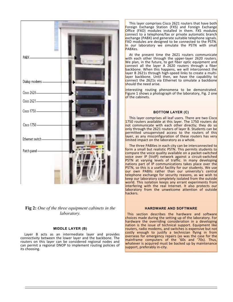
Fig 2: One of the three equipment cabinets in the
laboratory.
MIDDLE LAYER (B) Layer B acts as an intermediate layer and provides connectivity between the lower layer and the backbone. The routers on this layer can be considered regional nodes and can permit a regional DNOP to implement routing policies of its choosing.
This layer comprises Cisco 2621 routers that have bothForeign Exchange Station (FXS) and Foreign ExchangeOffice (FXO) modules installed in them. FXS modulesconnect to a telephone/fax or private automatic branchexchange (PABX) and generate suitable telephone signals.FXO modules are designed to be connected to the PSTN.In our laboratory we simulate the PSTN with smallPABXes.
At the present time the 2621 routers communicatewith each other through the upper‐layer 2620 routers.We plan, in the future, to get fiber optic equipment andconnect all the layer A 2620 routers through a fiberbackbone. When this happens, we will interconnect thelayer B 2621s through high‐speed links to create a multi‐layer backbone. Until then, we have the capability toconnect the 2621s via Ethernet to simulate a backboneshould the need arise.
interesting routing phenomena to be demonstrated.Figure 1 shows a photograph of the laboratory, Fig. 2 oneof the cabinets.
BOTTOM LAYER (C) This layer comprises all leaf users. There are two Cisco1750 routers available at this layer. The 1750 routers donot communicate with each other directly; they do soonly through the 2621 routers of layer B. Students can bepermitted unsupervised access to the routers of thislayer, as any misconfiguration of these routers has verylimited impact on the laboratory as a whole.
The three PABXes in each city can be interconnected toform a small but realistic PSTN. This permits students tocompare the voice quality available on a packet‐switchedvoice over IP (VoIP) network against a circuit‐switchedPSTN at varying levels of traffic. In many developingnations part of IP communications takes place over thePSTN, so this is a useful facility for our students. We useour own PABXs rather than our university’s centraltelephone exchange for security reasons, as we wish tokeep our laboratory completely isolated from the outsideworld. This isolation keeps any errant experiments frominterfering with the real Internet. It also protects ourlaboratory from the unwelcome attention of outsidehackers.
HARDWARE AND SOFTWARE This section describes the hardware and softwarechoices made during the setting up of the laboratory. Forhardware the overriding consideration in a developingnation is the issue of technical support. Equipment likerouters, radio modems, and switches is expensive but notcostly enough to justify a technician flying in fromoverseas for emergency repairs (as was the case for themainframe computers of the ’60s and ’70s). Thus,whatever is acquired must be backed up by maintenancesupport, preferably in‐city.
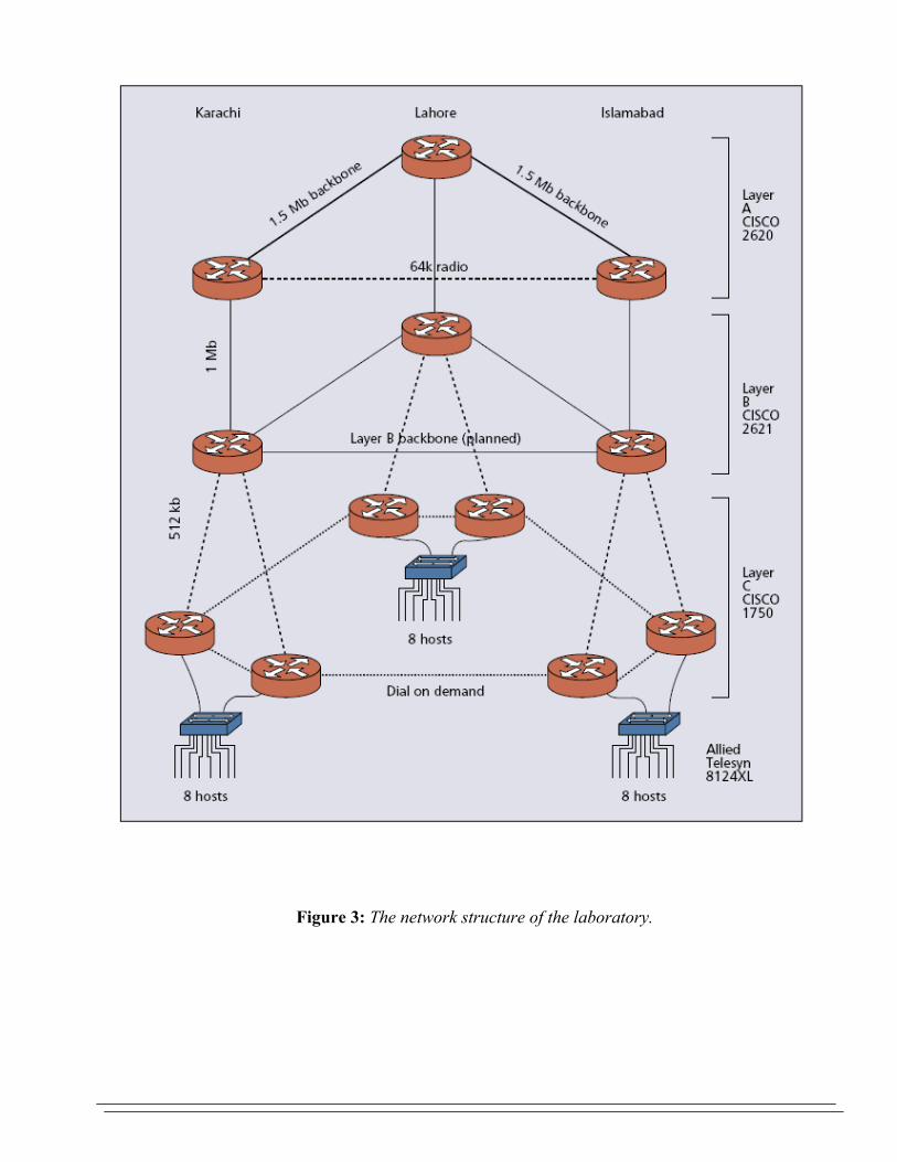
Figure 3: The network structure of the laboratory.
At the time laboratory was designed (2000), Cisco wasthe major player in the router market in Pakistan, with alarge fraction of the market share and extensive technicalsupport. At the present time many other companies haveentered the field, and a new laboratory being designedtoday could, in addition to Cisco, choose from 3Com,Alcatel, Allied Telesyn, Huawei, and Motorola, amongothers. Another important consideration for choosingCisco routers was that most potential employers wereusing Cisco equipment, so students trained on thesewould be in great demand. Similar considerations appliedto the other equipment discussed below.
ROUTERS
The routers chosen for this laboratory are the Cisco2620, 2621, and 1750. All of these routers are modular;that is, they have plug‐in modules that can be replaced asthe need arises (so, e.g., one may replace an Ethernetport with a Gigabit Ethernet port.) This is an importantconsideration for future expansion and modification ofour laboratory.
SWITCH
An Allied‐Telesyn model AT‐8124XL Fast Ethernetswitch is installed in each cabinet and can be used forvirtual LAN (VLAN) experiments. In addition tointroducing VLAN technology to our students, theseswitches reduce the cost of our network experiments, aseach can simulate multiple switches that would bedistributed over a real‐world organization.
RADIO MODEM
Radio modems operating on the unlicensed frequencyband (2300–2400 MHz) are very popular for datanetworking in the third world as well as rural areas of theindustrialized world, where existing copper infrastructureis poor and unreliable for last mile connectivity. We haveinstalled two Aircom Airlink S‐band radio modems in twoof our cities. Managing these modems is a useful exercisefor students.
The wireless link provided by these modems reducesthe hop count between Islamabad and Karachi by one(Fig. 3). We can set up our routing algorithm to use thislink as the preferred path between these two cities.However, as the capacity of the radio link (64 kb/s) is farless than the capacity of the alternate 1.5 Mb/s path, therouting algorithm switches over to the alernate pathwhen the radio modems saturate. This experiment vividlyillustrates the behavior of routing algorithms under loadconditions.
DIALUP MODEMS AND PABXS
We have added dialup modems to our lower layer tosimulate automatic dialup connections between routersin case of loss of backbone connectivity. This is animportant consideration in the developing world, andillustrates to students how the PSTN and IP networkscoexist at the present time. The PABXs and dialupmodems allow students to experiment with “dial backup”schemes. This equipment can also be used to simulate amodel Internet service provider (ISP) setup.
PATCH PANELS
Patch panels (bottom of Fig. 2) save wear and tear onports of expensive switches and routers because ofrepeated plugging and unplugging of connectors. It isstandard practice to terminate the most frequently usedports on patch panels. We have terminated each andevery port of every piece of equipment on these patchpanels. This permits us to rewire the entire laboratorywithout disturbing any expensive equipment.
HOSTS
We have 44 Intel PIII (733 MHz) PCs in our laboratory toact as hosts. They have 256 Mbytes RAM and 20‐Gbytehard disks. These machines have the Intel 815emotherboard but are otherwise unbranded. Themachines are assembled within Pakistan from mostlyimported parts, although casings and such are locallymade. Such machines perform well, and are cheaplymaintained and repaired. Use of such unbrandedmachines results in large cost savings. Furthermore, suchmachines can be freely opened, modified, andreconfigured, something that is not possible in mostbranded systems.
LINUX OPERATING SYSTEM
Our laboratory is completely Linux‐based. This is becauseof its stability, reliability, and low cost, and our extensiveprior experience with this operating system. All network‐ing functions are freely available for this operatingsystem; in addition, a wide range of free software isavailable for it through the Gnu project. Students trainedon Linux are comfortable with other variants of UNIX aswell as Solaris. Finally, Linux is commonly used by ISPsand other potential employers of our students inPakistan.
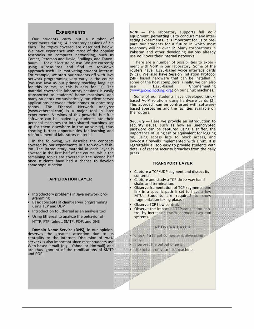
VoIP — The laboratory supports full VoIPequipment, permitting us to conduct many inter‐esting experiments. It is important for us to pre‐pare our students for a future in which mosttelephony will be over IP. Many corporations inPakistan and other developing nations alreadyuse VoIP over their internal networks.
There are a number of possibilities to experi‐ment with VoIP in our laboratory. Some of therouters have H.323‐based voice interface cards(VICs). We also have Session Initiation Protocol(SIP) based hardware that can be installed insome of the host computers. Finally, we can alsouse H.323‐based Gnomemeeting(www.gnomemeeting. org) on our Linux machines.
Some of our students have developed Linux‐based VoIP solutions using hardware cards [2].This approach can be contrasted with software‐based approaches and the facilities available onthe routers. Security — Here we provide an introduction tosecurity issues, such as how an unencryptedpassword can be captured using a sniffer, theimportance of using ssh or equivalent for loggingon, using access lists to block access, andlow‐cost firewalls implemented with Linux. It isregrettably all too easy to provide students withdetails of recent security breaches from the dailypress.
TRANSPORT LAYER
• Capture a TCP/UDP segment and dissect its contents.
• Capture and study a TCP three‐way hand‐shake and termination.
• Observe framentation of TCP segments: one link in a specific path is set to have a low MTU. Students are required to show fragmentation taking place.
• Observe TCP flow control. • Observe the impact of TCP congestion con‐
trol by increasing traffic between two end systems.
NETWORK LAYER
• Check if a target computer is alive using ping.
• Interpret the output of ping. • Use netstat on your host machine.
EXPERIMENTS
Our students carry out a number ofexperiments during 14 laboratory sessions of 2 heach. The topics covered are described below.We have experience with most of the populartextbooks on computer networking, such asComer, Peterson and Davie, Stallings, and Tanen‐baum for our lecture course. We are currentlyusing Kurose‐Ross and find its top‐downapproach useful in motivating student interest.For example, we start our students off with Javanetwork programming very early in the course(we use Java as our primary teaching languagefor this course, so this is easy for us). Thematerial covered in laboratory sessions is easilytransported to students’ home machines, andmany students enthusiastically run client‐serverapplications between their homes or dormitoryrooms. The Ethereal Network Analyzer(www.ethereal.com) is a major tool in laterexperiments. Versions of this powerful but freesoftware can be loaded by students into theirpersonal machines (or into shared machines setup for them elsewhere in the university), thuscreating further opportunities for learning andreinforcement of laboratory material.
In the following, we describe the conceptscovered by our experiments in a top‐down fash‐ion. The introductory material in each layer iscovered in the first half of the course, while theremaining topics are covered in the second halfonce students have had a chance to developsome sophistication.
APPLICATION LAYER
• Introductory problems in Java network pro‐
gramming • Basic concepts of client‐server programming
using TCP and UDP • Introduction to Ethereal as an analysis tool • Using Ethereal to analyze the behavior of
HTTP, FTP, telnet, SMTP, POP, and DNS Domain Name Service (DNS), in our opinion,
deserves the greatest attention due to itscentrality to the Internet. Discussion of mai lservers is also important since most students useWeb‐based email (e.g., Yahoo or Hotmail) andare thus ignorant of the ramifications of SMTPand POP.

Traceroute — List the path taken by a packet fromsource to destination. Justify why a specific path is beingfollowed. The laboratory administrator sets up a staticpath, and students are required to trace it and compare itwith the dynamic path used earlier. Note the delaysbetween various cities in the network. This material can beusefully augmented by homework assignments in whichstudents are challenged to find the most distant hostcomputer from their PCs (in terms of hops, time delays, orgeographical distance). Also covered are dissecting RIPbroadcasts and analyzing Open Shortest Path First (OSPF)messages.
Students log into a router and use IOS to investigate itscharacteristics (amount of memory, etc.), investigate theprocesses that are running, look at the status of allinterfaces, and study the status (load, queuing strategy,I/O packet drops, I/O errors) of each router in a city indetail. This is repeated under different load conditions.They use extended access lists to control access to arouter, and verify that their configurations work asexpected.
Dial on Demand Routing (DDR) — This is a
cost‐effective solution when we want to provide backupsupport for a network, if traffic is limited, if email onlyaccess is required, and in situations where real IPconnectivity is not yet set up. DDR is of great relevance tothe developing world, where Internet connectivity isnonuniform. In Pakistan small businesses use DDRextensively.
Network Management Systems — Commer‐ cially available network management systems, such asCisco Works, are beyond our financial resources. We have,however, developed a Javabased network managementsystem based on Simple Network Management Protocol(SNMP) to introduce students to this area.
DATA LINK LAYER
• Analysis of Ethernet frames • Analysis of ARP messages
PHYSICAL LAYER
This is perhaps the most interesting topic from theelectrical engineer’s point of view, and an area where ourstudents can differentiate themselves from computerscience and information technology graduates. Topicsinclude the waveforms used in various parts of the system(Ethernet ports, etc.) and the effect of externally appliednoise on the error rate in a data link.
EDUCATION and COURSES
Various courses are taught at both graduate andundergraduate levels. These courses provide students asound knowledge and wide range of concepts incomputer networking.
UNDERGRADUATE COURSES
Computer Networking Design and Analysis of Algorithms
GRADUATE COURSES Advanced Computer Networking Cryptanalysis
Attached is the list of experiments part of the computernetworking lab work at undergraduate level.
FUTURE PLANS
The laboratory has already encouraged many studentsto carry out interesting research projects on VoIP [2]and the Linux router [3]. Although we planned thelaboratory to be a resource for undergraduate students,we have found it to be of interest and value to Master’sstudents as well. A recent graduate level course wasenthusiastically received, although it did require greatereffort to develop experiments at a more sophisticatedlevel.
Finances and human resources permitting, our future
plans call for the augmentation of this laboratory with: Fiber optic links. These will permit demonstration of
and experimentation with high‐speed links. Studentswill be able to experiment with extremelyhigh‐bandwidth data transfers and observe theperformance of the routers under these stressfulconditions. Our plan is to acquire multikilometer spoolsof fiber so that latencies can be realisticallyexperienced.
A live VSAT connection from one cabinet to
another. This will permit us to experiment with thecontrasting bandwidths and latencies of VSATconnections and fiber optic or copper links.
Wireless networking. This technology is slowlygathering momentum in the developing world; itbehooves us to keep our students abreast of itsdevelopments.
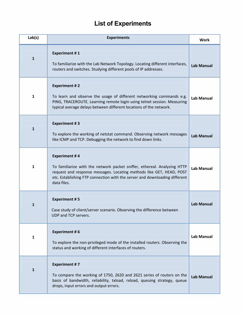
List of Experiments
Lab(s) Experiments Work
1
Experiment # 1
To familiarize with the Lab Network Topology. Locating different interfaces, routers and switches. Studying different pools of IP addresses.
Lab Manual
1
Experiment # 2
To learn and observe the usage of different networking commands e.g. PING, TRACEROUTE. Learning remote login using telnet session. Measuring typical average delays between different locations of the network.
Lab Manual
1
Experiment # 3
To explore the working of netstat command. Observing network messages like ICMP and TCP. Debugging the network to find down links.
Lab Manual
1
Experiment # 4 To familiarize with the network packet sniffer, ethereal. Analyzing HTTP request and response messages. Locating methods like GET, HEAD, POST etc. Establishing FTP connection with the server and downloading different data files.
Lab Manual
1
Experiment # 5
Case study of client/server scenario. Observing the difference between UDP and TCP servers.
Lab Manual
1
Experiment # 6 To explore the non‐privileged mode of the installed routers. Observing the status and working of different interfaces of routers.
Lab Manual
1
Experiment # 7 To compare the working of 1750, 2620 and 2621 series of routers on the basis of bandwidth, reliability, txload, rxload, queuing strategy, queue drops, input errors and output errors.
Lab Manual
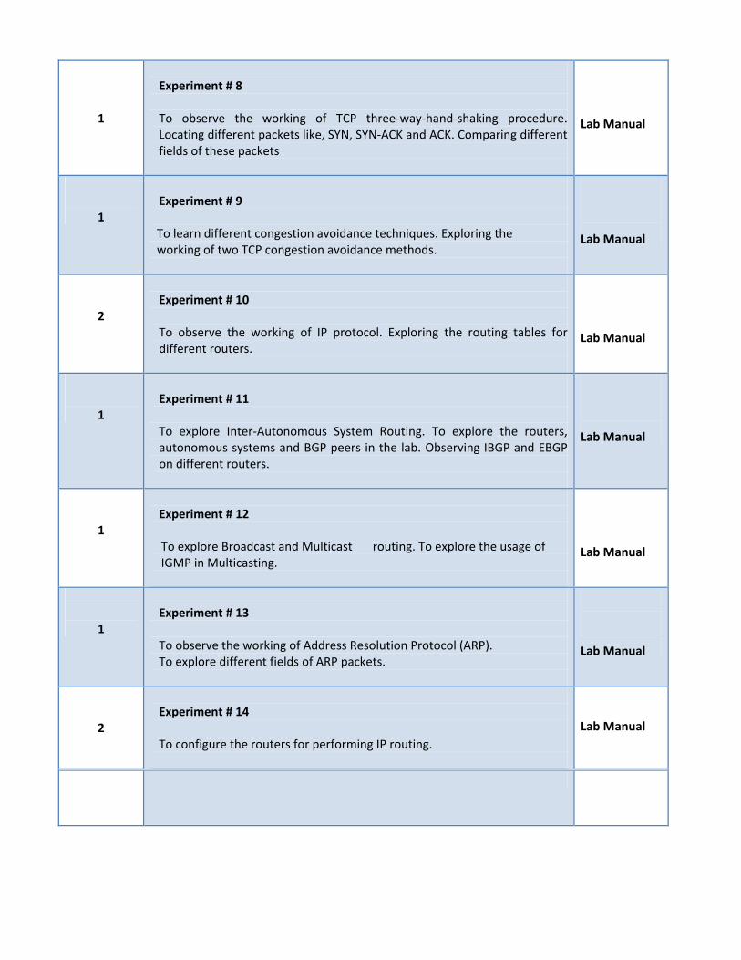
1
Experiment # 8 To observe the working of TCP three‐way‐hand‐shaking procedure. Locating different packets like, SYN, SYN‐ACK and ACK. Comparing different fields of these packets
Lab Manual
1
Experiment # 9 To learn different congestion avoidance techniques. Exploring the working of two TCP congestion avoidance methods.
Lab Manual
2
Experiment # 10 To observe the working of IP protocol. Exploring the routing tables for different routers.
Lab Manual
1
Experiment # 11 To explore Inter‐Autonomous System Routing. To explore the routers, autonomous systems and BGP peers in the lab. Observing IBGP and EBGP on different routers.
Lab Manual
1
Experiment # 12 To explore Broadcast and Multicast routing. To explore the usage of IGMP in Multicasting.
Lab Manual
1
Experiment # 13 To observe the working of Address Resolution Protocol (ARP). To explore different fields of ARP packets.
Lab Manual
2
Experiment # 14 To configure the routers for performing IP routing.
Lab Manual
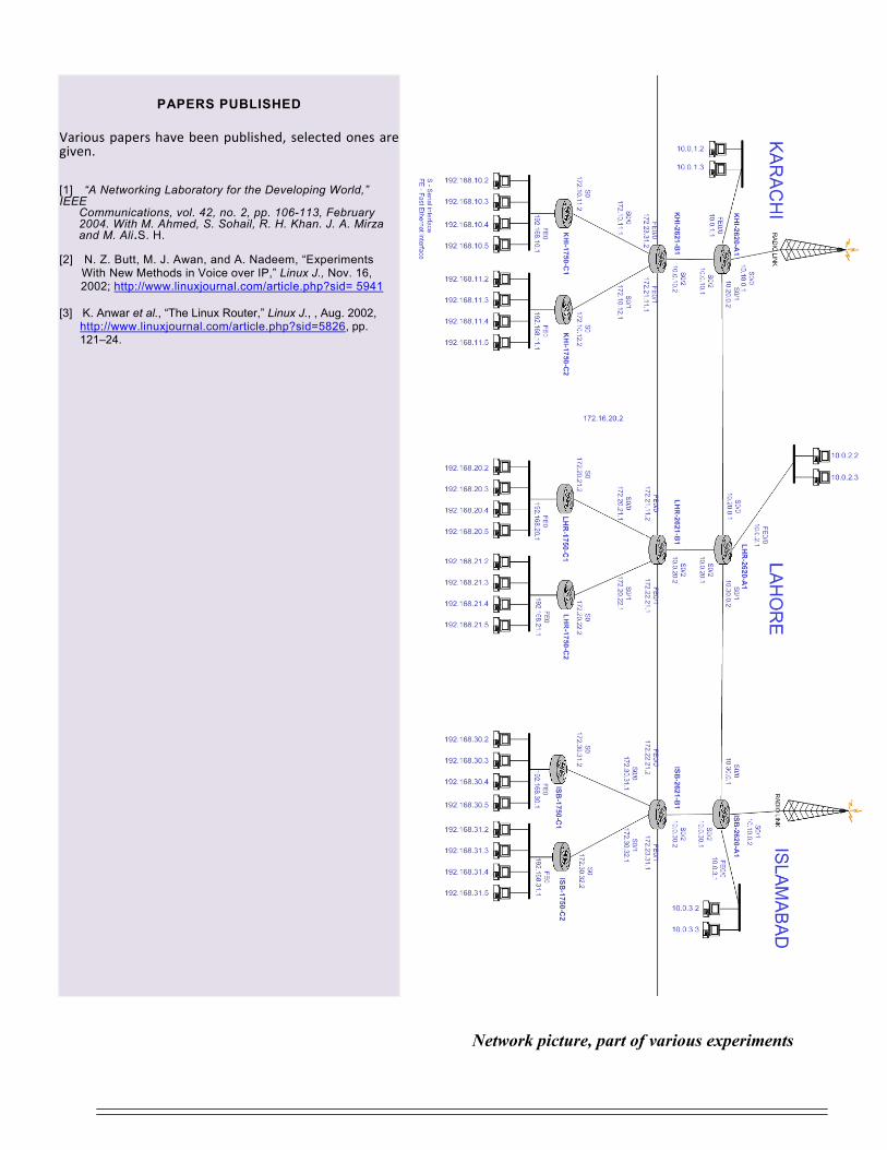
Network picture, part of various experiments
PAPERS PUBLISHED
Various papers have been published, selected ones are given.
[1] “A Networking Laboratory for the Developing World,” IEEE
Communications, vol. 42, no. 2, pp. 106-113, February 2004. With M. Ahmed, S. Sohail, R. H. Khan. J. A. Mirza and M. Ali.S. H.
[2] N. Z. Butt, M. J. Awan, and A. Nadeem, “Experiments With New Methods in Voice over IP,” Linux J., Nov. 16, 2002; http://www.linuxjournal.com/article.php?sid= 5941
[3] K. Anwar et al., “The Linux Router,” Linux J., , Aug. 2002, http://www.linuxjournal.com/article.php?sid=5826, pp. 121–24.

DEPARTMENT of ELECTRICAL ENGINEERING UNIVERSITY of ENGINEERING and TECHNOLOGY, LAHORE, PAKISTAN, 54890