compressive capacity of longitudinally cracked wood ... · compressive capacity of longitudinally...
TRANSCRIPT

Song et al. / J Zhejiang Univ-Sci A (Appl Phys & Eng) 2015 16(12):964-975 964
Compressive capacity of longitudinally cracked wood columns
retrofitted by self-tapping screws*
Xiao-bin SONG†, Ya-jie WU, Rui JIANG (Department of Structural Engineering, Tongji University, Shanghai 200092, China)
†E-mail: [email protected]
Received Mar. 20, 2015; Revision accepted Aug. 3, 2015; Crosschecked Nov. 10, 2015
Abstract: This paper presents the results of an experimental and numerical study of the compressive capacity of longitudinally cracked wooden columns retrofitted using self-tapping screws. The screws were driven into the wood perpendicular to the wood grain to alleviate the propagation of existing cracks and to improve the structural integrity of the cracked columns. Full-scale concentric and eccentric compression tests were conducted to investigate the failure modes and maximum load carrying capacity of such columns. A 3D finite element model was developed, verified, and then used for a parametric study. The test results indi-cated that the cracks (of 6 mm wide) caused a resistance loss of up to 19% compared with an intact column, but most of this resistance loss can be remedied by using self-tapping screws. It was also found that such resistance loss and recovery are de-pendent on the seriousness of the cracking, and generally increase with the increased initial mid-height deflection and decreased screw spacing, whereas a screw spacing of 100 mm would be sufficient for most cases considered in this study. Key words: Wood columns, Cracked, Self-tapping screws, Retrofitting, Finite element model doi:10.1631/jzus.A1500069 Document code: A CLC number: TU366.2
1 Introduction
Wood members of historical timber structures may experience significant damage and cracking during their service life due to fungal decay, mois-ture changes and/or external loadings. This damage and cracking may significantly affect the compres-sive behavior of wood columns and impair their load carrying capacity, especially when longitudinal cracks occur and propagate through the length of the timber. In such case, the reduced stability capacity (due to loss of structural integrity) may cause prema-ture failures. Retrofitting of such members is neces-sary and urgent to preserve the social and cultural values of historical timber structures.
A longitudinal crack in a wood column can di-vide the column into two separated limbs and cause resistance loss in two ways. The first is that any propagation of the crack can increase the unre-strained length of the two limbs, which are under eccentric compression, and thus decrease their load carrying capacity as a result of the increased slen-derness ratio. The second is through the loss of com-posite action between the two limbs causing these limbs to deflect separately, and the entire column capacity to be dominated by the capacity of the weaker limb.
Taking into account the failure mechanism of cracked wood columns, many techniques have been developed for retrofitting purposes, including the replacement of local damaged materials, the injec-tion of resin or other materials to fill cracks, the use of steel jackets or cages, and the use of fiber rein-forcing polymer (FRP) sheet wrapping (MOHURD, 1992; Plevris and Triantafillou, 1992; Davalos et al.,
* Project supported by the National Natural Science Foundation of China (No. 51478336), and the Scientific Research Foundation for the Re-turned Overseas Chinese Scholars, State Education Ministry, China
ORCID: Xiao-bin SONG, http://orcid.org/0000-0002-6271-053X © Zhejiang University and Springer-Verlag Berlin Heidelberg 2015
Journal of Zhejiang University-SCIENCE A (Applied Physics & Engineering)
ISSN 1673-565X (Print); ISSN 1862-1775 (Online)
www.zju.edu.cn/jzus; www.springerlink.com
E-mail: [email protected]
Song et al. / J Zhejiang Univ-Sci A (Appl Phys & Eng) 2015 16(12):964-975 965
1999; Chidiaq, 2003; Ehsani et al., 2004; Emerson, 2004; Oprisan et al., 2004; Najm et al., 2007; Foraboschi and Vanin, 2015). However, the material replacement and resin injection methods are essen-tially based on experience and the extent to which this promotes recovery is difficult to quantify, whilst the metallic confinement method has compatibility problems with wood, and rusted confinements may subsequently cause a second wave of damage. FRP wrapping has been proven to be an effective method for retrofitting wood columns (Zhang et al., 2012), but it may significantly affect the architectural ap-pearance of the wood itself. Moreover, retrofitting with FRP sheets is time-consuming regarding the gluing and hardening process of FRP sheets.
More recently, the use of self-tapping screws as reinforcement for wood materials, inserted in a perpendicular-to-wood-grain direction near the con-nections or openings, has been studied in depth (Blass and Schmid, 2001; Blass and Bejtka, 2004; Jönsson, 2005; Echavarría, 2007; Tannert and Lam, 2009; Gehloff et al., 2010). It was found that speci-mens which had been reinforced using this method exhibited more flexible resilience than the unrein-forced specimens by postponing the occurrence, or alleviating the propagation of perpendicular-to-wood-grain cracks. Trautz (2009) also reported that the self-tapping screws could significantly increase the shear stiffness of glulam beams. Crucially, the application of self-tapping screws does not require pre-drilling and is therefore much more time-efficient in terms of construction than the aforemen-tioned methods. However, no research work has sur-faced dealing with its application in retrofitting cracked wood columns against concentric or eccen-tric compression loads.
To fill this gap in our collective knowledge, a series of studies have been conducted at Tongji University which focus on retrofitting longitudinally cracked wood beams and columns using self-tapping screws. This paper presents the results of the retrofitting of longitudinally cracked wood col-umns under compression loading. Full-scale column tests were conducted to investigate the failure modes and maximum compression load of intact, cracked, and retrofitted wood columns under con-
centric and eccentric loading. A 3D finite element model was developed, verified, and used for an ex-tended study into the influence of these factors. As noted by Foraboschi (2013) and Foraboschi and Vanin (2014), it would not be feasible to maximize the screw confinement by reducing the screw spac-ing since closely driven screws may induce localized damage to the wood. Thus, the primary objective of this study is to identify a balanced screw spacing to ensure the prevention of crack propagation and to aid in the recombining of column limbs separated by existing cracks. 2 Experimental
The experimental study consisted of material property tests (including compression tests on parallel-to-wood-grain small clear specimens and pull-out tests of self-tapping screws) and concentric and eccentric compression tests on full-scale wood columns with and without artificially induced cracks.
2.1 Material property tests and results
Small clear wood specimens, 25 mm×25 mm× 100 mm in size, were taken from the damaged col-umn specimens near the failure zone after compres-sion column tests had been conducted. Five speci-mens were taken from each column specimen and numbered accordingly. The specimen tests were conducted parallel-to-wood-grain according to the specifications in ASTM standard D143-09 (ASTM, 2014). The loading rate was 0.3 mm/min. The aver-aged test results, including the modulus of elasticity, EL, and the parallel-to-wood-grain compression strength, fc, are listed in Table 1.
Fully threaded self-tapping screws, ASSY Plus
VG, supplied by a Germany based company, Wurth, in a diameter of 6 mm and a length of 200 mm, were tested for tensile strength. The nominal tensile strength was found to be 114.2 MPa with a coeffi-cient of variation of 0.028. Screws were also tested for bonding behavior with wood by drilling them into a wood block of 80 mm×80 mm×90 mm with a pen-etration depth of 5 times that of the screw diameter (30 mm in this study). The loading rate was

Song et al. / J Zhejiang Univ-Sci A (Appl Phys & Eng) 2015 16(12):964-975 966
1.74 mm/min. The nominal bonding stress, τ, was calculated as the quotient of the applied load and the nominal area (screw circumference multiplied by penetration length) of the bonding surface. The test setup and the test results of the maximum bonding stress, τu, and the initial stiffness, kb, based on 10 specimens are shown in Fig. 1.
2.2 Compression tests of wood columns
The main purpose of the compression tests of the wood columns was to evaluate the retrofitting efficiency of the self-tapping screws in concentric and eccentric loading scenarios, as well as to provide a database for verification of the 3D finite element model.
2.3 Column materials and specimen preparation
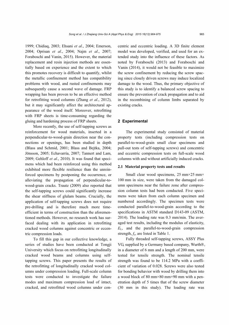
The column specimens were made from Doug-las fir lumber (Pseudotsuga menziesii var. menziesii) due to it being readily available. The lumber was randomly selected from a local mill. No grading was performed due to the lack of a technician at the mill although grading would ideally be preferred. The column specimens were cut into square cross-sections of 200 mm×200 mm and 2400 mm in length. An artificial crack was created along the longitudinal axis of some specimens to simulate a standardized cracking scenario. This was done by slotting together the columns at the middle point of the cross-section with a nominal width of 6 mm and over the middle 2000 mm of the total length of 2400 mm of the col-umns, as shown in Fig. 2. The crack width and length were determined following those outlined by Zhang et al. (2012) for comparison purposes. The corners of the slots were chamfered with a radius of 3 mm to avoid stress concentration.
In total six specimen groups, each containing
five specimens, were prepared for testing as listed in Table 1. Three specimen configurations, namely in-tact, cracked, and retrofitted columns, and two load-ing scenarios, concentric and eccentric with a load eccentricity, e, of 15 mm, were set up. The retrofitted columns were initially slotted with the specified crack width and retrofitted by applying self-tapping screws perpendicular to the cracking plane at a cer-tain spacing (250 mm was used in the tests), as shown in Fig. 2.
Table 1 Specimen configurations and averaged material property test results of the column specimens
Specimen group fc (MPa)* EL (MPa) Specimen status Replication
Concentric loading
S1 30.85 17 025 Intact 5
S2 29.36 21 402 Cracked 5
S3 28.01 16 042 Screw retrofitted 5
Eccentric loading (load eccentricity
e of 15 mm)
S4 30.63 19 856 Intact 5
S5 31.01 20 616 Cracked 5
S6 31.98 19 379 Screw retrofitted 5 * fc and EL were obtained from parallel-to-wood-grain small clear specimen compression tests with 25 specimens comprising each speci-men group
Fig. 1 Test setup (a) and averaged test results (b) of screw pull-out tests
(a)
Slip δ
τ
τu
kb
kb=8.55 N/mm3 τu=7.01 N/mm2
(b)
Song et al. / J Zhejiang Univ-Sci A (Appl Phys & Eng) 2015 16(12):964-975 967
2.4 Testing frame and loading scheme
The column specimens were placed vertically and simply supported at both ends: the bottom end rested on a steel plate, and the upper end was con-nected to the loading head of a hydraulic actuator using a knife-edge bearing plate. Both the steel plate and the knife-edge bearing plate were adjustable for eccentric loading, and were free to rotate around the weak axis of the column cross-sections, i.e., parallel with the artificial crack.
The compression load was applied by means of a hydraulic actuator at a speed of nearly 0.5 kN/s. Steel supports were placed beside the column speci-mens (with no contact) to prevent unexpected lateral deflections.
Before testing, the specimens were measured for initial lateral deflection (crookedness) e0 at mid-height cross-section, cross-section dimension, and moisture content. The moisture content was found to be rough-ly 17% on average. An initial loading of roughly 25% of the estimated maximum load was applied twice to remove any potential loose contact between the bear-ing plates and the specimen ends. Subsequently, the specimens were loaded up to the point of failure or when the load dropped to 85% of the maximum load. The layout of the testing frame is also shown in Fig. 2.
2.5 Data measurement
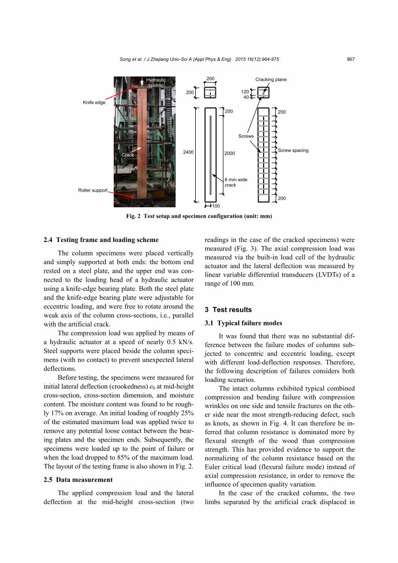
The applied compression load and the lateral deflection at the mid-height cross-section (two
readings in the case of the cracked specimens) were measured (Fig. 3). The axial compression load was measured via the built-in load cell of the hydraulic actuator and the lateral deflection was measured by linear variable differential transducers (LVDTs) of a range of 100 mm. 3 Test results
3.1 Typical failure modes
It was found that there was no substantial dif-ference between the failure modes of columns sub-jected to concentric and eccentric loading, except with different load-deflection responses. Therefore, the following description of failures considers both loading scenarios.
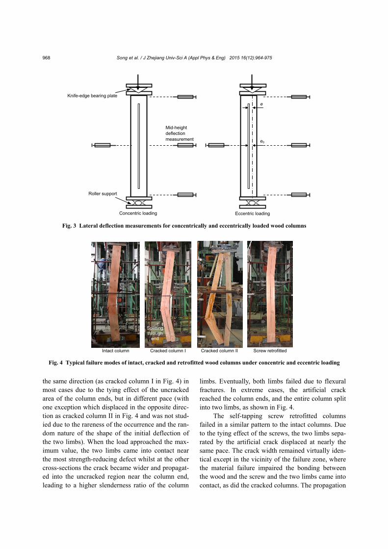
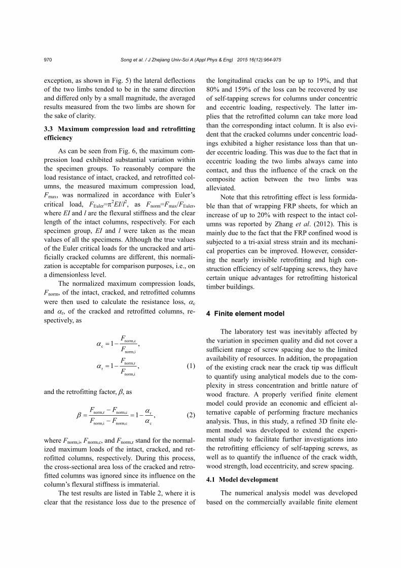
The intact columns exhibited typical combined compression and bending failure with compression wrinkles on one side and tensile fractures on the oth-er side near the most strength-reducing defect, such as knots, as shown in Fig. 4. It can therefore be in-ferred that column resistance is dominated more by flexural strength of the wood than compression strength. This has provided evidence to support the normalizing of the column resistance based on the Euler critical load (flexural failure mode) instead of axial compression resistance, in order to remove the influence of specimen quality variation.
In the case of the cracked columns, the two limbs separated by the artificial crack displaced in
Fig. 2 Test setup and specimen configuration (unit: mm)
Crack
Knife edge
Roller support
Hydraulic loading
2400
200
200
2000
200
40120
200
Screw spacing
6 mm wide crack
Screws
200
Cracking plane
100
Song et al. / J Zhejiang Univ-Sci A (Appl Phys & Eng) 2015 16(12):964-975 968
the same direction (as cracked column I in Fig. 4) in most cases due to the tying effect of the uncracked area of the column ends, but in different pace (with one exception which displaced in the opposite direc-tion as cracked column II in Fig. 4 and was not stud-ied due to the rareness of the occurrence and the ran-dom nature of the shape of the initial deflection of the two limbs). When the load approached the max-imum value, the two limbs came into contact near the most strength-reducing defect whilst at the other cross-sections the crack became wider and propagat-ed into the uncracked region near the column end, leading to a higher slenderness ratio of the column
limbs. Eventually, both limbs failed due to flexural fractures. In extreme cases, the artificial crack reached the column ends, and the entire column split into two limbs, as shown in Fig. 4.
The self-tapping screw retrofitted columns failed in a similar pattern to the intact columns. Due to the tying effect of the screws, the two limbs sepa-rated by the artificial crack displaced at nearly the same pace. The crack width remained virtually iden-tical except in the vicinity of the failure zone, where the material failure impaired the bonding between the wood and the screw and the two limbs came into contact, as did the cracked columns. The propagation
Fig. 4 Typical failure modes of intact, cracked and retrofitted wood columns under concentric and eccentric loading
Intact column Cracked column I Screw retrofitted
Splitting through
end
Cracked column II
Fig. 3 Lateral deflection measurements for concentrically and eccentrically loaded wood columns
Knife-edge bearing plate
Roller support
Mid-height deflection measurement
Concentric loading Eccentric loading
e
e0

Song et al. / J Zhejiang Univ-Sci A (Appl Phys & Eng) 2015 16(12):964-975 969
of the crack towards the uncracked region was also well restrained. An example of a typical failure is shown in Fig. 4.
3.2 Load and mid-height lateral deflection curves
Typical load and mid-height lateral deflection curves are shown in Fig. 5. As is evident, the mid-height lateral deflections, measured from the two separated limbs of the cracked columns, increased at different paces whilst those of retrofitted columns increased at almost the same pace and in the same direction, in both concentric and eccentric loading tests, with increased loading. This implied a better composite action caused by the tying effect of the screws.
For comparison and model verification purpos-es, the load and mid-height lateral deflection curves of all intact, cracked, and screw retrofitted columns, tested concentrically and eccentrically, are shown in Fig. 6. Since in most cases (with only one noted
Fig. 6 Averaged load and mid-height lateral deflection curves of concentrically and eccentrically loaded columns
Fig. 5 Typical lateral deflection development of the two limbs of concentrically (a) and eccentrically (b) loaded columns with cracks
(b)
(a)
Song et al. / J Zhejiang Univ-Sci A (Appl Phys & Eng) 2015 16(12):964-975 970
exception, as shown in Fig. 5) the lateral deflections of the two limbs tended to be in the same direction and differed only by a small magnitude, the averaged results measured from the two limbs are shown for the sake of clarity.
3.3 Maximum compression load and retrofitting efficiency
As can be seen from Fig. 6, the maximum com-pression load exhibited substantial variation within the specimen groups. To reasonably compare the load resistance of intact, cracked, and retrofitted col-umns, the measured maximum compression load, Fmax, was normalized in accordance with Euler’s critical load, FEuler=
2EI/l2, as Fnorm=Fmax/FEuler, where EI and l are the flexural stiffness and the clear length of the intact columns, respectively. For each specimen group, EI and l were taken as the mean values of all the specimens. Although the true values of the Euler critical loads for the uncracked and arti-ficially cracked columns are different, this normali-zation is acceptable for comparison purposes, i.e., on a dimensionless level.
The normalized maximum compression loads, Fnorm, of the intact, cracked, and retrofitted columns were then used to calculate the resistance loss, c and r, of the cracked and retrofitted columns, re-spectively, as
norm,cc
norm,i
1 ,F
F
norm,rr
norm,i
1 ,F
F (1)
and the retrofitting factor, , as
norm,r norm,c r
norm,i norm,c c
1 ,F F
F F
(2)
where Fnorm,i, Fnorm,c, and Fnorm,r stand for the normal-ized maximum loads of the intact, cracked, and ret-rofitted columns, respectively. During this process, the cross-sectional area loss of the cracked and retro-fitted columns was ignored since its influence on the column’s flexural stiffness is immaterial.
The test results are listed in Table 2, where it is clear that the resistance loss due to the presence of
the longitudinal cracks can be up to 19%, and that 80% and 159% of the loss can be recovered by use of self-tapping screws for columns under concentric and eccentric loading, respectively. The latter im-plies that the retrofitted column can take more load than the corresponding intact column. It is also evi-dent that the cracked columns under concentric load-ings exhibited a higher resistance loss than that un-der eccentric loading. This was due to the fact that in eccentric loading the two limbs always came into contact, and thus the influence of the crack on the composite action between the two limbs was alleviated.
Note that this retrofitting effect is less formida-ble than that of wrapping FRP sheets, for which an increase of up to 20% with respect to the intact col-umns was reported by Zhang et al. (2012). This is mainly due to the fact that the FRP confined wood is subjected to a tri-axial stress strain and its mechani-cal properties can be improved. However, consider-ing the nearly invisible retrofitting and high con-struction efficiency of self-tapping screws, they have certain unique advantages for retrofitting historical timber buildings. 4 Finite element model
The laboratory test was inevitably affected by the variation in specimen quality and did not cover a sufficient range of screw spacing due to the limited availability of resources. In addition, the propagation of the existing crack near the crack tip was difficult to quantify using analytical models due to the com-plexity in stress concentration and brittle nature of wood fracture. A properly verified finite element model could provide an economic and efficient al-ternative capable of performing fracture mechanics analysis. Thus, in this study, a refined 3D finite ele-ment model was developed to extend the experi-mental study to facilitate further investigations into the retrofitting efficiency of self-tapping screws, as well as to quantify the influence of the crack width, wood strength, load eccentricity, and screw spacing.
4.1 Model development
The numerical analysis model was developed based on the commercially available finite element

Song et al. / J Zhejiang Univ-Sci A (Appl Phys & Eng) 2015 16(12):964-975 971
method software, Abaqus®, chosen for its robust computational capacity and user friendly graphic interface. The wood columns and the self-tapping screws were simulated using the embedded 8-node linear hexahedral reduced integration element, C3D8R.
Wood was assumed to be orthotropic in the lin-ear elastic stage. The parallel-to-wood-grain modu-lus of elasticity, EL, was determined based on the small clear specimen tests, as listed in Table 1. The modulus of elasticity in the radial and tangential di-rections, the modulus of rigidity, G, and Poisson’s ratio, v, in the three principal planes were determined using the commonly accepted ratios to EL (Simpson and TenWolde, 1999) due to their complexity in la-boratory testing.
In the nonlinear stage, wood was assumed to be isotropic to evade the consistency and closed yield-ing surface requirements (Hong, 2007). The nonline-ar stress-strain relationship was established based on the parallel-to-wood-grain compression test results taking into consideration the nature of the compres-sion failures of the wood columns. The relationship can be mathematically described as
2
0 c pp
d p c p u
, ,
( ) , ,
E f
E f
(3)
where σ and are the stress and strain; E0 and Ed are the modulus of elasticity and the slope of the de-scending branch of the stress-strain curve, respec-tively, as shown in Fig. 7, with E0 taken as EL and Ed taken as 10% of E0; p is the strain corresponding to
the peak stress and can be determined as 2fc/E0; u is the ultimate strain and was determined as p+ 0.15fc/Ed assuming that wood fails when the stress reaches 85% of the peak stress on the descending branch of the stress-strain curve.
The parallel-to-wood-grain compression strength fc must be adjusted to take into account the differ-ence between the geometries of the small clear spec-imens and the wood columns. According to Weibull’s weakest link theory (Weibull, 1939), the strength adjustment can be done as follows:
1/
c,a s
c column
,
kf V
f V
(4)
where fc,a is the adjusted strength; Vs and Vcolumn are the volumes of the small clear specimens and the wood columns, respectively; k is the size effect fac-tor. In this study, the size effect factor k was deter-mined based on the comparison of the maximum concentric compression load of small clear speci-mens, wood columns of 2400 mm, and wood col-umns of 1800 mm long. The latter was reported pre-viously by Song et al. (2012). The mean value of the size effect factor k was set as 6.58.
Generally speaking, the self-tapping screws and the bonding behavior can be considered as contact elements, which often require higher computation capacity and may cause convergence difficulty. In this study, since no apparent bonding failure was observed in the tests, the screws were simulated us-ing an equivalent stiffness, i.e., the bonding slippage (2δ) of the screws was lumped to the screw segment within the width of the artificial crack as the elastic elongation :
b eq
22 ,
π
F Fw
Dlk E A
(5)
where F is any given force carried by a screw; D is the screw diameter; l is the penetration depth of the screw into the wood; kb is the initial bonding stiff-ness of the screws determined by the pull-out tests; w is the crack width; Eeq is the modulus of elasticity of the equivalent spring; A is the cross-sectional area of the spring, as shown in Fig. 8.
Fig. 7 A parallel-to-wood-grain compressive stress-strain curve model
Ed
p u fc/E0
E0
fc
σ

Song et al. / J Zhejiang Univ-Sci A (Appl Phys & Eng) 2015 16(12):964-975 972
Assuming that the equivalent spring has the same diameter as the screws, Eeq can then be calcu-lated as
beq
2.
wlkE
D
(6)
Consequently, the entire self-tapping screw can
be assumed to have the same Eeq, while those sur-rounded by wood are rigidly connected with the wood elements. The stress concentration effect on the wood surrounding the screws was not considered as the global lateral deflection of the entire column, instead of the screw pulling out or wood crushing near the screws, dominated the member failure.
In addition to the artificial cracks, the model al-so considered the initial mid-height lateral deflection, e0, which can be introduced into the wood columns due to the changes of humidity and temperature. The distribution of the initial deflection along the height of the columns was assumed to be half-sinusoidal with the maximum at the mid-height cross-section. Averaged measurements of e0 from the column spec-imens, as listed in Table 2, were used as the model input. The generated model is shown in Fig. 9 for illustrative purposes.
4.2 Model verification
The model predictions of the load-mid-height-lateral-deflection curves of the six specimen groups are shown in comparison with the test results in Fig. 6, where a positive correlation between the ini-tial stiffness and the maximum load can be observed. As indicated in Table 2, the modeling error of the maximum compression load is less than 6%. 5 Parametric studies
A parametric study was conducted using the
verified model to further investigate the influence of the initial lateral deflection, screw spacing, and the load eccentricity on the retrofitting efficiency of the self-tapping screws. The initial lateral deflection e0 was considered for cracked columns, since in most practical cases cracks, once formed, will continue to spread and cause crookedness of the column limbs, while not affecting the cross-sectional area. For sim-plicity and to be conservative in our considerations, in this parametric study the two limbs of a cracked
Table 2 Maximum loads and retrofitting effect of concentrically and eccentrically loaded wood columns
Specimen group FEuler
(kN) e0 (mm)1
Fmax (kN) Fmax/FEulerResistance
loss, Retrofitting
factor,
Modeling result
Left Right Fmax (kN) Error (%)
Concentric loading
S1 4267 −0.1 0.5 776 (0.15)2 0.18 0 – 762 −1.80
S2 4889 −0.1 0.5 735 (0.16) 0.15 0.19 – 703 −4.35
S3 3665 −0.5 1.0 643 (0.18) 0.18 0.04 0.80 666 3.58
Eccentric loading
S4 4536 0.3 −0.3 600 (0.13) 0.13 0 – 631 5.17
S5 4710 0.1 0.4 586 (0.18) 0.12 0.06 – 605 3.24
S6 4427 1.0 −0.2 606 (0.20) 0.14 −0.03 1.59 622 2.64
Note: 1 signs of the measured initial mid-height lateral deflection of the two limbs were defined with respect to a common reference direc-tion; 2 within parentheses are the coefficient of variations of the measured maximum load Fmax
Fig. 8 Equivalent bonding spring of self-tapping screws
A A
δ δ
w
F
A-A
l/2
C. L.
d
Wood column
Artificial crack
Screw
F F
Equivalent spring

Song et al. / J Zhejiang Univ-Sci A (Appl Phys & Eng) 2015 16(12):964-975 973
column are assumed to have the same initial deflec-tion, when moving in opposite and outward direction. For example, an initial deflection of 5 mm and a 6 mm wide crack will eventually cause a crack of 16 mm wide.
The parametric study was based on two scenar-ios, as listed in Table 3. The first scenario (PS1) represents a generic scenario, in which the column carries small initial deflection when subjected to a concentric load; whilst in the second scenario (PS2) the column suffers material deterioration (a strength factor of 0.6) and a load eccentricity of 30 mm and carries significant initial deflections. The initial de-flection will cause a crack width at the mid-height cross-section of 36 mm, a state where retrofitting is mandatory, as stated in the technical code for maintenance and strengthening of ancient timber buildings (MOHURD, 1992).
Based on the two scenarios (PS1 and PS2) var-ied initial mid-height deflections (5, 10, 15, 20, 25, and 30 mm) and self-tapping screw spacings (50, 100, 250, and 500 mm) were considered to calculate the maximum compression loads of intact, cracked, and retrofitted columns. The resistance loss of the cracked columns and the retrofitting factor of the screw retrofitted columns were determined. The re-sults are shown in Fig. 10.
It can be seen that both the resistance loss and the retrofitting factor increase with the increased mid-height initial deflection. In the first scenario, the column is mildly cracked and concentrically loaded
Table 3 Parametric study scenarios based on tested specimen group S3
Specimen group
Initial mid-height deflec-tion, e0 (mm)
Load eccen-tricity, e
(mm)
Strength reduction
factor PS1 5 0 1.0
PS2 15 30 0.6
Model Intact Cracked I Cracked II Retrofitted
Fig. 9 Finite element method based column model and modeling results
Fig. 10 Variation of retrofitting factor of wood columns sampled with different self-tapping screw spacing (a) and initial mid-height deflections (b)
(a)
(b)
Self-tapping screw spacing (mm)

Song et al. / J Zhejiang Univ-Sci A (Appl Phys & Eng) 2015 16(12):964-975 974
and the resistance loss and the retrofitting factor can be up to 17% and 80%, respectively. In the second scenario, where the column is seriously cracked and subjected to eccentric loading, the resistance loss and the retrofitting factor can be up to 10% and 105%, respectively. A mid-height initial deflection of 30 mm implies a significant loss of compression re-sistance (more than 10%), when provision of self-tapping screws as reinforcement can achieve approx-imately 100% recovery of the resistance. Such indi-ces can be used as reference for thresholds where screw reinforcing is both necessary and efficient.
Meanwhile, the retrofitting factor is also affect-ed by the self-tapping screw spacing. In the first sce-nario, the retrofitting factor decreases slightly with the increased screw spacing and is nearly 55% for a spacing of 500 mm, whilst in the second scenario it decreases from 110% to 65%, the latter correspond-ing to a screw spacing of 500 mm. A screw spacing of 100 mm leads to a retrofitting factor of approxi-mately 1.0, i.e., all resistance loss due to the pres-ence of a crack can be recovered by using the screws. 6 Conclusions
This paper presents the results of an experi-mental and numerical study of the compressive ca-pacity of longitudinally cracked wood columns retro-fitted using self-tapping screws. Based on the test results and parametric analysis results, the following conclusions can be drawn:
1. Longitudinal cracks impair column resistance by increasing unrestrained length as existing cracks propagate, and weakening the composite action be-tween column limbs, leading to a lower resistance dominated by the weaker limb.
2. The self-tapping screws can prevent the propagation of existing cracks and retie the separated limbs, by means of a biting action between screw threads and the wood, thus recovering much of the resistance loss caused by the cracks.
3. The resistance loss escalates with increased initial crookedness induced by the cracked opening, as does the retrofitting efficiency of using self-tapping screws. A mid-height initial deflection (crookedness) of 30 mm was suggested as the threshold for reinforcing provision.
4. The retrofitting efficiency generally increases with decreased screw spacing, and a spacing of 100 mm was suggested as the most efficient spacing for a column of 2400 mm high and 200 mm×200 mm in cross-section.
Due to limited recourses, this study focused predominantly on cracks at symmetrical axes of the column cross-sections, as it can be assumed from elementary knowledge of mechanics that an asym-metric crack can lead to a much weaker limb than a symmetric crack (although the other limb will be stronger), and thus may result in a more significant loss of column resistance. Only limited column ge-ometry, slenderness ratio, and crack width were con-sidered for the reason mentioned above. These issues will be addressed in future studies. References ASTM (American Society for Testing and Materials), 2014.
Standard Test Methods for Small Clear Specimens of Timber, ASTM D143-14. American Society for Testing and Materials, West Conshohocken, USA.
Blass, H.J., Schmid, M., 2001. Self-tapping screws as rein-forcement perpendicular to the grain in timber connec-tions. International RILEM Symposium, RILEM Publi-cations S.A.R.L., Stuttgart, Germany.
Blass, H.J., Bejtka, I., 2004. Reinforcement perpendicular to the grain using self-tapping screws. The 8th World Con-ference on Timber Engineering, Lahti, Finland, Vol. 1.
Chidiaq, R., 2003. Axial compression of rounded wood poles reinforced with carbon fibers. MSc Special Project, De-partment of Civil Engineering, Rutgers, State University of New Jersey, Piscataway, USA.
Davalos, J.F., Zipfel, M.G., Qiao, P., 1999. Feasibility study of prototype GFRP-reinforced wood railroad crosstie. Journal of Composites for Construction, 3(2):92-99. [doi:10.1061/(ASCE)1090-0268(1999)3:2(92)]
Echavarría, C., 2007. Bolted timber joints with self-tapping screws. Revista EIA, (8):37-47.
Ehsani, M., Larsen, M., Palmer, N., 2004. Strengthening of old wood with new technology. Structure, p.19-21.
Emerson, R.N., 2004. In situ repair technique for decayed timber piles. Proceedings of Building on the Future, Se-curing the Past Conference, Nashville, USA, p.1-9. [doi:10.1061/40700(2004)65]
Foraboschi, P., 2013. Church of San Giuliano di Puglia: seis-mic repair and upgrading. Engineering Failure Analysis, 33:281-314. [doi:10.1016/j.engfailanal.2013.05.023]
Foraboschi, P., Vanin, A., 2014. Experimental investigation on bricks from historical Venetian buildings subjected to moisture and salt crystallization. Engineering Failure Analysis, 45:185-203. [doi:10.1016/j.engfailanal.2014.06. 019]
Foraboschi, P., Vanin, A., 2015. Mechanical behavior of the

Song et al. / J Zhejiang Univ-Sci A (Appl Phys & Eng) 2015 16(12):964-975 975
timber-terrazzo composite floor. Construction and Build-ing Materials, 80:295-314. [doi:10.1016/j.conbuildmat. 2015.01.068]
Gehloff, M., Closen, M., Lam, F., 2010. Reduced edge distances in bolted timber moment connections with perpendicular to grain reinforcements. Proceeding of the World Conference on Timber Engineering, Vol. 230.
Hong, J.P., 2007. Three-dimensional Nonlinear Finite Ele-ment Model for Single and Multiple Dowel-type Wood Connections. PhD Thesis, University of British Colum-bia, Vancouver, Canada.
Jönsson, J., 2005. Load carrying capacity of curved glulam beams reinforced with self-tapping screws. Holz als Roh-und Werkstoff, 63(5):342-346. [doi:10.1007/s00107-005-0016-5]
MOHURD (Ministry of Housing and Urban-Rural Develop-ment of the People’s Republic of China), 1992. Tech-nical code for maintenance and strengthening of ancient timber buildings, GB50165-92. Chinese National Stand-ard, China Architecture and Building Press, Beijing, China (in Chinese).
Najm, H., Secaras, J., Balaguru, P., 2007. Compression tests of circular timber column confined with carbon fibers using inorganic matrix. Journal of Materials in Civil En-gineering, 19(2):198-204. [doi:10.1061/(ASCE)0899-1561(2007)19:2(198)]
Oprisan, G., Taranu, N., Entuc, I.S., 2004. Strengthening of the timber members using fiber reinforced polymer composites. The Bulletin of the Polytechnic Institute of Jassy, Construction. Architecture Section, p.67-76.
Plevris, N., Triantafillou, T.C., 1992. FRP-reinforced wood as structural material. Journal of Materials in Civil Engi-neering, 4(3):300-317. [doi:10.1061/(ASCE)0899-1561 (1992)4:3(300)]
Simpson, W., TenWolde, A., 1999. Wood Handbook: Wood as an Engineering Material. General Technical Report FPL-GTR-113, Department of Agriculture, Forest Service, Forest Products Laboratory, Madison, USA.
Song, X.B., Jiang, R., Zhang, W.P., et al., 2012. Compressive behavior of longitudinally cracked wood columns retro-fitted by self-tapping screws. Proceeding of the World Conference on Timber Engineering, Auckland, New Zealand.
Tannert, T., Lam, F., 2009. Self-tapping screws as reinforce-ment for rounded dovetail connections. Structural Con-trol and Health Monitoring, 16(3):374-384. [doi:10. 1002/stc.283]
Trautz, M., 2009. Self-tapping screws as reinforcement for timber structures. Proceedings of the International Asso-ciation for Shell and Spatial Structures Symposium, Va-lencia, Spain.
Weibull, W., 1939. A Statistical Theory of the Strength of Materials. Generalstabens litografiska anstalts förlag, Stockholm.
Zhang, W.P., Song, X.B., Gu, X.L., et al., 2012. Compressive behavior of longitudinally cracked timber columns retro-fitted using FRP sheets. Journal of Structural Engineer-ing, 138(1):90-98. [doi:10.1061/(ASCE)ST.1943-541X. 0000423]
中文概要 题 目:新型自攻螺丝修复纵裂木柱抗压性能
目 的:受压纵裂木柱缝端应力集中会引起裂缝发展和
两侧木材协同工作性能下降,并削弱木柱抗压
承载力。以试验和数值模拟探讨轴压和偏压作
用下纵裂木柱抗压承载力的下降规律,分析自
攻螺丝的修复机理,推导纵裂木柱修复临界值
和最优螺丝间距。
创新点:1. 以自攻螺丝实现纵裂木柱抗压承载力快速有
效和不影响外观的修复目标;2. 以试验和数值
模拟推导纵裂木柱承载力显著下降而需修复的
临界值以及自攻螺丝间距的最优取值。
方 法:1. 通过带纵缝木柱抗压试验研究纵缝及自攻螺
丝对木柱承载力的影响;2. 运用精细化有限元
数值模拟方法,基于清样小试件木材力学测试
结果,建立带纵缝木柱有限元模型;3. 运用有
限元模型开展参数分析,归纳整理纵缝宽度及
自攻螺丝间距等主要参数对木柱承载力修复效
果的影响。
结 论:1. 纵裂木柱抗压承载力下降主要由缝端应力集
中引起的裂缝开展和缝两侧木材协同工作性能
下降引起;2. 新型自攻螺丝垂直裂缝方向贯入
可实现有效拉结,从而延缓裂缝开展和恢复木
材协同工作性能;3. 纵裂木柱承载力下降比率
和自攻螺丝修复率均随裂缝宽度的增加而增
加;4. 本文中 30 mm 的柱中裂缝宽度可导致木
柱承载力下降超过 10%,因而可作为修复的临
界值,而 100 mm 的自攻螺丝间距可基本实现
100%的承载力修复,因而可作为最优螺丝
间距。
关键词:纵裂木柱;新型自攻螺丝;承载力修复;有限
元数值模拟