compression tube fittings cat sec - i rev 1 - aura...
TRANSCRIPT

Aura Inc. “Process Control – Building the Core”
Aura Fluid Connectors
ww.aurainc.com

AURA COMPRESSION TUBE FITTINGS
CONTENTS
ABOUT US Page 1 - 2 OVERVIEW Page 3 SPECIFICATIONS Page 4 ASSEMBLY Page 5 TESTING PROCEDURES Page 6 - 7 PRODUCT INDEX Page 8 - 9 PRODUCT DRAWINGS AND COMPETITIVE INTERCHANGE
Page 10 - 50
QUALITY Page 51 - 54 CERTIFICATIONS Page 55 - 56
AI: CAT: ATF: REV 0:06/16/05

1
AURA ABOUT US
Aura designs , manufactures and provides Fluid Connectors, Needle Valves,
Instrument Manifolds, RTD/Thermocouple sensors and it’s associated
accessories. Aura was founded in 1995 in India with a 100% owned
subsidiary in the United States. Our customers range in size and scope
across the globe : from upstream to down stream oil and gas, Refinery,
Petrochemical complexes, Major Power and Utility companies, Biotech and
Food Processing, Fertilizer and Chemicals, HVAC, Temperature and Pressure
sensor OEM’s. Our 100% owned state of the art manufacturing facilities in
New Delhi – India spans 8000 square feet and uses CNC machines, Lathe,
Traub and other special purpose machines to produce high precision products
and “custom built “ parts and has been ISO 9001:2000 compliant since 2001
as certified by TUV Germany.
At Aura our mission is clear and unequivocal: to help our clients gain and
sustain competitive advantage. We accomplish this goal through a continuous
process of innovation and maintaining complete control of the entire supply
chain: in house manufacturing and our owned warehousing and distribution
in the United States and India. Complementing this we have our extensive
network of distributors in Europe, Africa and Asia which allows us to service
clients on the ground.
Our products meet almost all global standards and conform to BS 4368 Part
IV, Alberta Boiler Safety Association (ABSA), Technical Safety and Standards
Authority (TSSA )- Canada to name a few.

2
AURA ABOUT US
We service more than 145 clients in the United States and Canada since
1997 and a proud list of clients in India, Europe and Middle East. Major
approvals include: EIL, NTPC, BHEL, PDIL, Emerson, Yokogawa, ABB,
Honeywell, Western Gauge, Gulf Petroleum, Aramco - Al Khaliji Joint
Venture, Bangladesh Gas, Siirtec Nigi, Pyromation, to name a few.
Our Good Manufacturing Practices cover quality systems for design,
manufacturing, packaging, labeling, storage, installation and shipping. At Aura
we follow a 100% QA procedure in that no parts are shipped without
inspection and that all raw material are 3rd party spectrographic tested for
specification. With Material tracing, internal stage wise documentation, web
based order tracking systems, we have automated our supply chain and the
effort persists.
Our management team has built three successful enterprises. We have
hundreds of years of corporate experience at ABB, Yokogawa Electric
Corporation, Emerson, Jacobs, Foster Wheeler, Rockwell Automation.
Internally, we respect our talented personnel and their creative spirits and
love them like our own family. We’ve learnt that greatest successes are
achieved when vision and execution work hand in hand and that personal
touch must always take priority over procedures when it comes to customer
service. These virtues allows us to compete and stand tall against much
larger global rivals and attain yet another year of stellar performance. Our dual
development approach : leveraging facilities across multiple locations and
time zones helps us achieve a 24x7 solution.

3
AURA COMPRESSION TUBE FITTINGS OVERVIEW AURA double ferrule compression fittings have attained an unmatched reputation as precision components that eliminate costly, hazardous leaks in Instrumentation and process tubing.
The product range includes :
TUBE TO MALE THREAD : Male Connector, Male Elbow, Male Run Tee, Male Branch Tee, Male Adapter.
TUBE TO FEMALE THREAD : Female Connector, Female Elbow, Female Run Tee, Female Branch Tee, Female Adapter.
TUBE TO TUBE : Straight Union, Bulkhead Union, Reducing Union, Union Elbow, Union Tee, Union Cross.
ACCESSORIES : Reducer, Tube End Closure, Fitting End Closure, Hex Nut, Front Ferrule, Back Ferrule.
AURA double ferrule Compression Fittings are available from 1/16” OD to 1” OD tubing and are machined from SS 316 which meet specifications of ASTM. Fittings design meets the requirement codes of : ANSI B31.1 - for Power Piping ANSI B31.3 - for Petroleum Refinery & Chemical Plants ASME Sec VIII - for Boiler & Pressure Vessels The Advantages of such fittings are : - Facility of assembling with self aligning front and back rings. - Low tightening torque (the nut is of non-binding design). - Controlled tightening effect, distortion of the tube without rupture of fibers,
minimum reduction of tube bore size. - No twisting of the tube when fitting. - Withstands high vacuum and pressure. - Re-usable, can be assembled and taken apart several times. - Recommended for use with thin and thick walled tube. AURA precision tube fittings are available with NPT/BSPT/BSP/ISO/UNF Threads. As part of the standard QA program, all Aura fittings conform to various test procedures as adapted and laid down by such standard as BS 4368 Part IV. As a standard design, the nut threads are silver plated so as to increase their resistance to seizing and galling of nuts on body.
4
AURA COMPRESSION TUBE FITTINGS SPECIFICATIONS
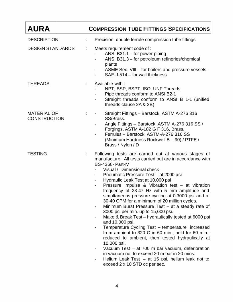
DESCRIPTION : Precision double ferrule compression tube fittings
DESIGN STANDARDS : Meets requirement code of : - ANSI B31.1 – for power piping - ANSI B31.3 – for petroleum refineries/chemical
plants - ASME Sec. VIII – for boilers and pressure vessels. - SAE-J-514 – for wall thickness
THREADS : Available with : - NPT, BSP, BSPT, ISO, UNF Threads - Pipe threads conform to ANSI B2-1 - Straight threads conform to ANSI B 1-1 (unified
threads clause 2A & 2B)
MATERIAL OF CONSTRUCTION
: - Straight Fittings – Barstock, ASTM A-276 316 SS/Brass.
- Angle Fittings – Barstock, ASTM A-276 316 SS / Forgings, ASTM A-182 G F 316, Brass.
- Ferrules – Barstock, ASTM-A-276 316 SS (Minimum Hardness Rockwell B – 90) / PTFE / Brass / Nylon / D
TESTING : Following tests are carried out at various stages of manufacture. All tests carried out are in accordance with BS-4368- Part-IV
- Visual / Dimensional check - Pneumatic Pressure Test – at 2000 psi - Hydraulic Leak Test at 10,000 psi - Pressure Impulse & Vibration test – at vibration
frequency of 23-47 Hz with 5 mm amplitude and simultaneous pressure cycling at 0-3000 psi and at 30-40 CPM for a minimum of 20 million cycles.
- Minimum Burst Pressure Test – at a steady rate of 3000 psi per min. up to 15,000 psi.
- Make & Break Test – hydraulically tested at 6000 psi and 10,000 psi.
- Temperature Cycling Test – temperature increased from ambient to 320 C in 60 min., held for 60 min., reduced to ambient, then tested hydraulically at 10,000 psi.
- Vacuum Test – at 700 m bar vacuum, deterioration in vacuum not to exceed 20 m bar in 20 mins.
- Helium Leak Test – at 15 psi, helium leak not to exceed 2 x 10 STD cc per sec.
5
AURA COMPRESSION TUBE FITTINGS ASSEMBLY
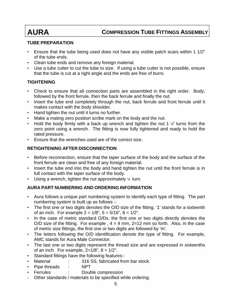
TUBE PREPARATION
• Ensure that the tube being used does not have any visible patch scars within 1 1/2” of the tube ends.
• Clean tube ends and remove any foreign material. • Use a tube cutter to cut the tube to size. If using a tube cutter is not possible, ensure
that the tube is cut at a right angle and the ends are free of burrs.
TIGHTENING
• Check to ensure that all connection parts are assembled in the right order. Body, followed by the front ferrule, then the back ferrule and finally the nut.
• Insert the tube end completely through the nut, back ferrule and front ferrule until it makes contact with the body shoulder.
• Hand tighten the nut until it turns no further. • Make a mating zero position scribe mark on the body and the nut. • Hold the body firmly with a back up wrench and tighten the nut 1 ¼” turns from the
zero point using a wrench. The fitting is now fully tightened and ready to hold the rated pressure.
• Ensure that the wrenches used are of the correct size.
RETIGHTENING AFTER DISCONNECTION
• Before reconnection, ensure that the taper surface of the body and the surface of the front ferrule are clean and free of any foreign material.
• Insert the tube end into the body and hand tighten the nut until the front ferrule is in full contact with the taper surface of the body.
• Using a wrench, tighten the nut approximately ¼ turn.
AURA PART NUMBERING AND ORDERING INFORMATION
• Aura follows a unique part numbering system to identify each type of fitting. The part numbering system is built up as follows :-
• The first one or two digits denotes the O/D size of the fitting. ‘1’ stands for a sixteenth of an inch. For example 2 = 1/8”, 5 = 5/16”, 8 = 1/2”.
• In the case of metric standard O/Ds, the first one or two digits directly denotes the O/D size of the fitting. For example , 4 = 4 mm, 2=12 mm so forth. Also, in the case of metric size fittings, the first one or two digits are followed by ‘m’.
• The letters following the O/D identification denote the type of fitting. For example, AMC stands for Aura Male Connector.
• The last one or two digits represent the thread size and are expressed in sixteenths of an inch. For example, 2=1/8”, 8 = 1/2”.
• Standard fittings have the following features:- • Material : 316 SS, fabricated from bar stock. • Pipe threads : NPT • Ferrules : Double compression • Other standards / materials to be specified while ordering.

6
AURA COMPRESSION TUBE FITTINGS TESTING PROCEDURES
1. VISUAL EXAMINATION :
Fittings are checked for overall finish, workmanship and dimensions. Dimensional checks are carried out using Ring / Plug step gauges (with minimum / Maximum limits) and go/no-go gauges.
2. PNEUMATIC PRESSURE TEST :
Test assemblies of suitable length are prepared with different sizes and types of fittings, tube fittings tightened 11/4 turn past snug. Each test assembly is then pressurized to 2000 psi pneumatic and is kept for fifteen minutes under pressure. If no leakage is found, the assembly is disassembled and inspected per paragraph7.
3. HYDRAULIC TEST :
After the completion of pneumatic test, the test assemblies are tightened 1¼ turn past snug, and the loop pressurized to 10,000 psi Hydraulic / Hydrostatic pressure and kept for 15 minutes. If no leakage is found, the assembly is disassembled and inspected per paragraph 7.
4. PRESSURE IMPULSE & VIBRATION TEST :
• After the completion of Hydraulic test, the test assemblies are tightened 1 ¼ turn past snug.
• The test assembly is subjected to vibration frequency in the range of 23-47 Hz with an amplitude of 5 mm and simultaneous pressure cycling at 0-3000 psi and at 35 + 5 cpm with the Hydraulic / Hydrostatic media.
• This test is run for a minimum of 30,00,000 vibration cycles along with pressure impulse. No leakage will be allowed.
• On completion of test, the test pieces are disassembled and inspected per paragraph 7.
5. MAKE & BREAK HYDROSTATIC TEST
• After completion of pressure impulse and vibration test, the test assemblies are tightened 1 1/4 turn past snug.
• The test assemblies are then assembled and disassembled. This operation is repeated five times.
• The test assembly is then pressurized to 60000 psi hydraulically / hydrostatically, held under this pressure for five minutes and checked for leaks.
• If no leakage is found, the pressure is released and the “make and break” operation is repeated 25 times.
7
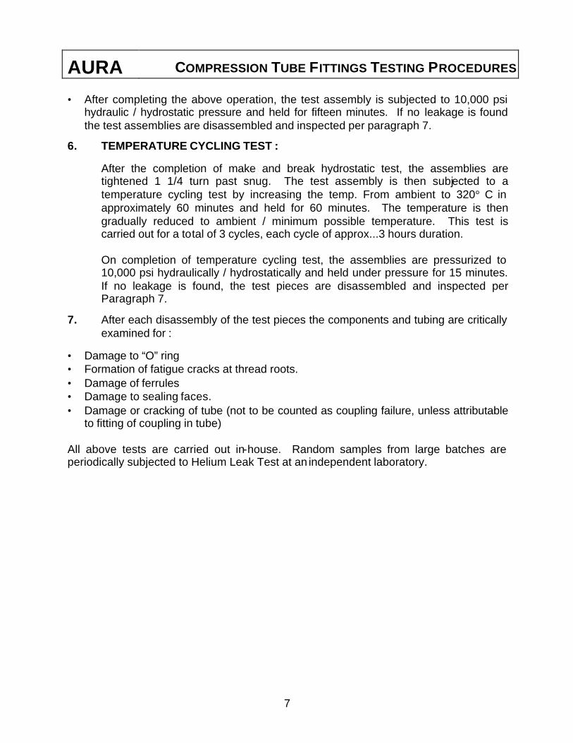
AURA COMPRESSION TUBE FITTINGS TESTING PROCEDURES • After completing the above operation, the test assembly is subjected to 10,000 psi
hydraulic / hydrostatic pressure and held for fifteen minutes. If no leakage is found the test assemblies are disassembled and inspected per paragraph 7.
6. TEMPERATURE CYCLING TEST :
After the completion of make and break hydrostatic test, the assemblies are tightened 1 1/4 turn past snug. The test assembly is then subjected to a temperature cycling test by increasing the temp. From ambient to 320° C in approximately 60 minutes and held for 60 minutes. The temperature is then gradually reduced to ambient / minimum possible temperature. This test is carried out for a total of 3 cycles, each cycle of approx...3 hours duration.
On completion of temperature cycling test, the assemblies are pressurized to 10,000 psi hydraulically / hydrostatically and held under pressure for 15 minutes. If no leakage is found, the test pieces are disassembled and inspected per Paragraph 7.
7. After each disassembly of the test pieces the components and tubing are critically examined for :
• Damage to “O” ring • Formation of fatigue cracks at thread roots. • Damage of ferrules • Damage to sealing faces. • Damage or cracking of tube (not to be counted as coupling failure, unless attributable
to fitting of coupling in tube) All above tests are carried out in-house. Random samples from large batches are periodically subjected to Helium Leak Test at an independent laboratory.

8
AURA COMPRESSION TUBE FITTINGS
PRODUCT INDEX
ITEM PART ITEM PART
Male Connector
AMC
Page 10-11
Male Elbow
AME
Page 12-13
Male Run Tee
AMRT
Page 14-15
Male Branch Tee
AMBT
Page 16-17
Male Adapter
AMA
Page 18-19
Female Connector
AFC
Page 20-21
Female Elbow
AFE
Page 22-23
Female Run Tee
AFRT
Page 24-25
Female Branch Tee
AFBT
Page 26-27
Female Adapter
AFA
Page 28-29
Straight Union
ASU
Page 30-31
Bulkhead Union
ABU
Page 32-33
9
AURA COMPRESSION TUBE FITTINGS
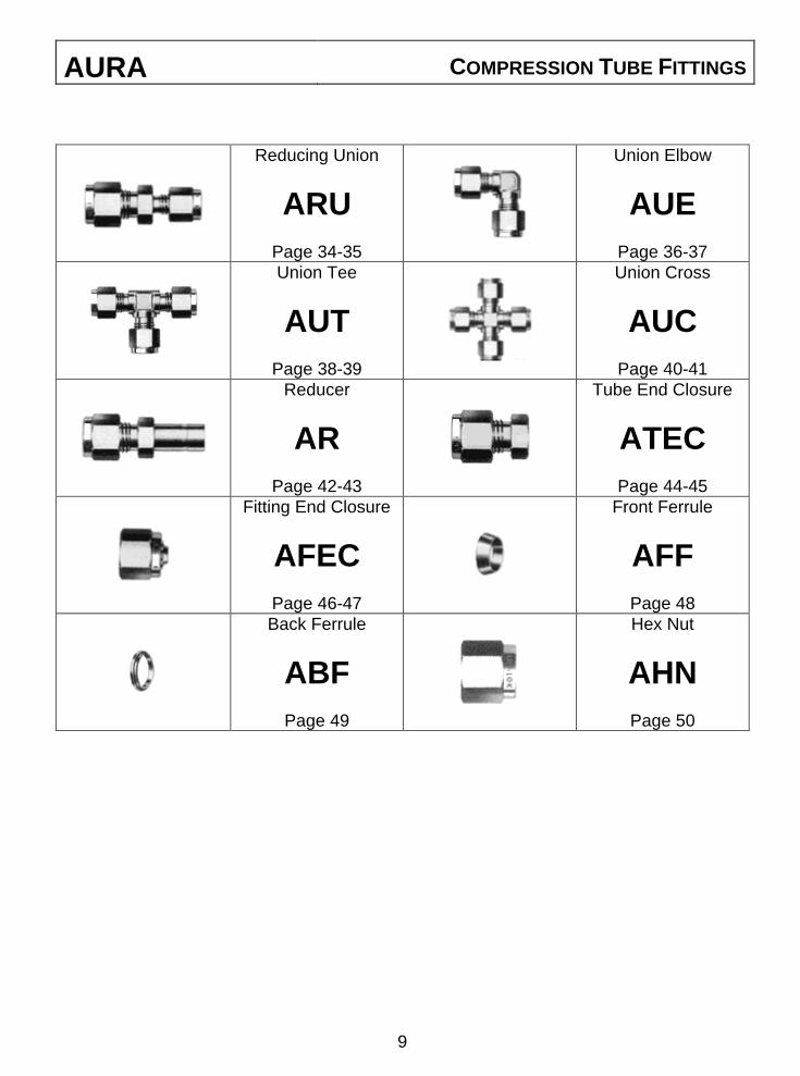
Reducing Union
ARU
Page 34-35
Union Elbow
AUE
Page 36-37
Union Tee
AUT
Page 38-39
Union Cross
AUC
Page 40-41
Reducer
AR
Page 42-43
Tube End Closure
ATEC
Page 44-45
Fitting End Closure
AFEC
Page 46-47
Front Ferrule
AFF
Page 48
Back Ferrule
ABF
Page 49
Hex Nut
AHN
Page 50

AURA MALE CONNECTOR
G F
P
H
T
E
B
A
C
D
• INCH SIZE TUBING AURA ‘T’ ‘P’ A B C D E F G H PART NO. TUBE OD NPT
2AMC2 1/8” 1/8” 1.19 0.38 0.60 0.50 0.09 7/16 7/16 0.93 2AMC4 1/8” 1/4” 1.39 0.56 0.60 0.50 0.09 9/16 7/16 1.13 4AMC2 1/4” 1/8" 1.28 0.38 0.70 0.60 0.19 1/2 9/16 0.99 4AMC4 1/4” 1/4” 1.48 0.56 0.70 0.60 0.19 9/16 9/16 1.19 4AMC6 1/4” 3/8” 1.50 0.56 0.70 0.60 0.19 11/16 9/16 1.21 4AMC8 1/4” 1/2” 1.75 0.75 0.70 0.60 0.19 7/8 9/16 1.46 5AMC4 5/16” 1/4” 1.51 0.56 0.73 0.64 0.25 9/16 5/8 1.22 6AMC2 3/8" 1/8” 1.38 0.38 0.76 0.66 0.19 5/8 11/16 1.09 6AMC4 3/8" 1/4” 1.56 0.56 0.76 0.66 0.28 5/8 11/16 1.27 6AMC6 3/8” 3/8” 1.56 0.56 0.76 0.66 0.28 11/16 11/16 1.27 6AMC8 3/8" 1/2” 1.81 0.75 0.76 0.66 0.28 7/8 11/16 1.52 8AMC4 1/2” 1/4” 1.70 0.56 0.86 0.901 0.28 13/16 7/8 1.30 8AMC6 1/2” 3/8” 1.70 0.56 0.86 0.90 0.38 13/16 7/8 1.30 8AMC8 1/2” 1/2” 1.92 0.75 0.86 0.90 0.41 7/8 7/8 1.52
8AMC12 1/2” 3/4” 1.98 0.75 0.86 0.90 0.41 1-1/16 7/8 1.58 10AMC6 5/8” 3/8” 1.73 0.56 0.86 0.96 0.38 15/16 1 1.33 10AMC8 5/8” 1/2” 1.92 0.75 0.86 0.96 0.47 15/16 1 1.52 12AMC8 3/4” 1/2” 1.98 0.75 0.86 0.96 0.47 1-1/16 1-1/8 1.58
12AMC12 3/4” 3/4” 1.98 0.75 0.86 0.96 0.62 1-1/16 1-1/8 1.58 12AMC16 3/4” 1” 2.24 0.94 0.86 0.96 0.62 1-3/8 1-1/8 1.84 14AMC12 7/8” 3/4” 1.98 0.75 0.86 1.02 0.62 1-3/16 1-1/4 1.58 16AMC12 1” 3/4” 2.25 0.75 1.04 1.23 0.62 1-3/8 1-1/2 1.77 16AMC16 1” 1” 2.44 0.94 1.04 1.23 0.88 1-3/8 1-1/2 1.96 • METRIC SIZE TUBING AURA ‘T’ ‘P’ A B C D E F G H PART NO. TUBE OD NPT ~ ~ ~ A/F A/F 3m AMC2 3 1/8” 30.3 09.5 9.7 15.3 12.9 12 12 23.7 3m AMC4 3 1/4” 35.4 14.2 15.3 12.9 2.4 14 12 28.8 6m AMC2 6 1/8" 32.6 9.7 17.7 15.3 4.6 14 14 25.2 6m AMC4 6 1/4” 37.7 14.2 17.7 15.3 4.8 14 14 30.3 6m AMC6 6 3/8” 38.2 14.2 17.7 15.3 4.8 18 14 30.8 6m AMC8 6 1/2” 44.5 19.0 17.7 15.3 4.8 22 14 37.1 8m AMC4 8 1/4” 34.0 9.7 18.6 16.2 4.8 15 16 36.5 8m AMC6 8 3/8” 38.5 14.2 18.6 16.2 6.4 15 16 31.1 8m AMC8 8 1/2” 45.4 19.0 18.6 16.2 6.4 22 16 37.9
10m AMC4 10 1/4” 40.7 14.2 19.5 17.2 7.9 18 19 33.1 10m AMC6 10 3/8” 40.7 14.2 19.5 17.2 7.9 18 19 33.1 10m AMC8 10 1/2” 46.3 19.0 19.5 17.2 7.9 22 19 38.7 12m AMC4 12 1/4” 43.2 14.2 22.0 22.8 7.1 22 22 33.1 12m AMC6 12 3/8” 43.2 14.2 22.0 22.8 9.5 22 22 33.1 12m AMC8 12 1/2” 48.8 19.0 22.0 22.8 9.5 22 22 38.7 16m AMC6 16 3/8” 43.9 14.2 22.0 24.4 9.5 24 25 33.8 16m AMC8 16 1/2” 48.8 19.0 22.0 24.4 11.9 24 25 38.7 16m AMC12 16 3/4” 50.3 19.0 22.0 24.4 12.7 27 25 40.2 20m AMC12 20 3/4” 52.1 19.0 22.0 26.0 15.9 30 32 42.0 20m AMC16 20 1” 56.9 23.9 22.0 26.0 18.3 35 32 46.8 25m AMC12 25 3/4” 57.3 19.0 26.5 31.3 15.9 35 38 45.0 25m AMC16 25 1” 62.1 23.9 26.5 31.3 21.8 35 38 49.8
10
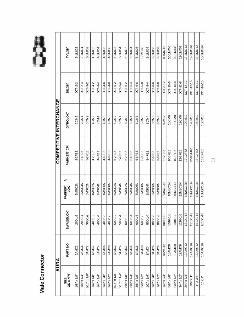
Mal
e C
on
nec
tor
AU
RA
C
OM
PE
TIT
IVE
INT
ER
CH
AN
GE
SIZ
E
OD
x N
PT
PA
RT
NO
S
WA
GE
LOK®
P
AR
KE
R®
A
LOK
P
AR
KE
R® C
PI
GY
RO
LOK
®
BIL
OK®
T
YL
OK®
1/8"
x 1
/8"
2AM
C2
20
0-1-
2 2M
SC
2N
2-2F
BZ
2CM
2 D
CT
-2-2
2-
1M
C-2
1/8"
x 1
/4"
2AM
C4
20
0-1-
4 2M
SC
4N
2-4F
BZ
2CM
4 D
CT
-2-4
2-
1M
C-4
3/16
" x
1/8"
3A
MC
2
300-
1-2
3MS
C2N
3-
2FB
Z 3C
M2
DC
T-3
-2
3-1
MC-
2
1/4"
x 1
/8"
4AM
C2
40
0-1-
2 4M
SC
2N
4-2F
BZ
4CM
2 D
CT
-4-2
4-
1M
C-2
1/4"
x 1
/4"
4AM
C4
40
0-1-
4 4M
SC
4N
4-4F
BZ
4CM
4 D
CT
-4-4
4-
1M
C-4
1/4"
x 3
/8"
4AM
C6
40
0-1-
6 4M
SC
6N
4-6F
BZ
4CM
6 D
CT
-4-6
4-
1M
C-6
1/4"
x 1
/2"
4AM
C8
40
0-1-
8 4M
SC
8N
4-8F
BZ
4CM
8 D
CT
-4-8
4-
1M
C-8
5/16
" x
1/8"
5A
MC
2
500-
1-2
5MS
C2N
5-
2FB
Z 5C
M2
DC
T-5
-2
5-1
MC-
2
5/16
" x
1/4"
5A
MC
4
500-
1-4
5MS
C4N
5-
4FB
Z 5C
M4
DC
T-5
-4
5-1
MC-
4
3/8"
x 1
/8"
6AM
C2
60
0-1-
2 6M
SC
2N
6-2F
BZ
6CM
2 D
CT
-6-2
6-
1M
C-2
3/8"
x 1
/4"
6AM
C4
60
0-1-
4 6M
SC
4N
6-4F
BZ
6CM
4 D
CT
-6-4
6-
1M
C-4
3/8"
x 3
/8"
6AM
C6
60
0-1-
6 6M
SC
6N
6-6F
BZ
6CM
6 D
CT
-6-6
6-
1M
C-6
3/8"
x 1
/2"
6AM
C8
60
0-1-
8 6M
SC
8N
6-8F
BZ
6CM
8 D
CT
-6-8
6-
1MC-
8
1/2"
x 1
/4"
8AM
C4
80
0-1-
4 8M
SC
4N
8-4F
BZ
8CM
4 D
CT
-8-4
8-
1M
C-4
1/2"
x 3
/8"
8AM
C6
80
0-1-
6 8M
SC
6N
8-6F
BZ
8CM
6 D
CT
-8-6
8-
1M
C-6
1/2"
x 1
/2"
8AM
C8
80
0-1-
8 8M
SC
8N
8-8F
BZ
8CM
8 D
CT
-8-8
8-
1M
C-8
1/2"
x 3
/4"
8AM
C12
80
0-1-
12
8MS
C12
N
8-12
FBZ
8CM
12
DC
T-8
-12
8-1M
C-1
2
5/8"
x 3
/8"
10A
MC
6
1010
-1-6
10
MS
C6N
10
-6FB
Z 10
CM
6 D
CT
-10
-6
10-1
MC-
6
5/8"
x 1
/2"
10A
MC
8
1010
-1-8
10
MS
C8N
10
-8FB
Z 10
CM
8 D
CT
-10
-8
10-1
MC-
8
3/4"
x 1
/2"
12A
MC
8
1210
-1-8
12
MS
C8N
12
-8FB
Z 12
CM
8 D
CT
-12
-8
12-1
MC-
8
3/4"
x 3
/4"
12A
MC
12
1210
-1-1
2 12
MS
C12
N
12-1
2FB
Z 12
CM
12
DC
T-12
-12
12-1
MC-
12
3/4"
X 1
” 12
AM
C16
12
10-1
-16
12M
SC
16N
12
-16-
FB
Z 12
CM
16
DC
T-12
-16
12-1
MC-
16
1” X
3/4
" 16
AM
C12
16
10-1
-12
16M
SC
12N
16
-12F
BZ
16C
M12
D
CT-
16-1
2 16
-1M
C-12
1” X
1”
16A
MC
16
1610
-1-1
6 16
MS
C16
N
16-1
6FB
Z 16
CM
16
DC
T-16
-16
16-1
MC-
16
11
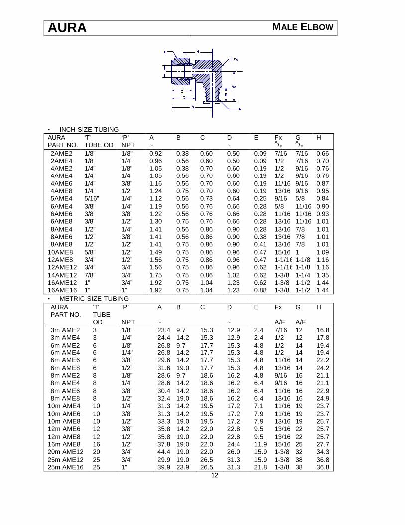
AURA MALE ELBOW
• INCH SIZE TUBING AURA ‘T’ ‘P’ A B C D E Fx G H PART NO. TUBE OD NPT ~ ~ A/F A/F 2AME2 1/8” 1/8” 0.92 0.38 0.60 0.50 0.09 7/16 7/16 0.66 2AME4 1/8” 1/4” 0.96 0.56 0.60 0.50 0.09 1/2 7/16 0.70 4AME2 1/4” 1/8" 1.05 0.38 0.70 0.60 0.19 1/2 9/16 0.76 4AME4 1/4” 1/4” 1.05 0.56 0.70 0.60 0.19 1/2 9/16 0.76 4AME6 1/4” 3/8” 1.16 0.56 0.70 0.60 0.19 11/16 9/16 0.87 4AME8 1/4” 1/2” 1.24 0.75 0.70 0.60 0.19 13/16 9/16 0.95 5AME4 5/16” 1/4” 1.12 0.56 0.73 0.64 0.25 9/16 5/8 0.84 6AME4 3/8" 1/4” 1.19 0.56 0.76 0.66 0.28 5/8 11/16 0.90 6AME6 3/8” 3/8” 1.22 0.56 0.76 0.66 0.28 11/16 11/16 0.93 6AME8 3/8" 1/2” 1.30 0.75 0.76 0.66 0.28 13/16 11/16 1.01 8AME4 1/2” 1/4” 1.41 0.56 0.86 0.90 0.28 13/16 7/8 1.01 8AME6 1/2” 3/8” 1.41 0.56 0.86 0.90 0.38 13/16 7/8 1.01 8AME8 1/2” 1/2" 1.41 0.75 0.86 0.90 0.41 13/16 7/8 1.01
10AME8 5/8” 1/2” 1.49 0.75 0.86 0.96 0.47 15/16 1 1.09 12AME8 3/4” 1/2” 1.56 0.75 0.86 0.96 0.47 1-1/16 1-1/8 1.16 12AME12 3/4” 3/4” 1.56 0.75 0.86 0.96 0.62 1-1/16 1-1/8 1.16 14AME12 7/8” 3/4” 1.75 0.75 0.86 1.02 0.62 1-3/8 1-1/4 1.35 16AME12 1” 3/4” 1.92 0.75 1.04 1.23 0.62 1-3/8 1-1/2 1.44 16AME16 1” 1” 1.92 0.75 1.04 1.23 0.88 1-3/8 1-1/2 1.44 • METRIC SIZE TUBING AURA ‘T’ ‘P’ A B C D E Fx G H PART NO. TUBE OD NPT ~ ~ A/F A/F 3m AME2 3 1/8” 23.4 9.7 15.3 12.9 2.4 7/16 12 16.8 3m AME4 3 1/4” 24.4 14.2 15.3 12.9 2.4 1/2 12 17.8 6m AME2 6 1/8" 26.8 9.7 17.7 15.3 4.8 1/2 14 19.4 6m AME4 6 1/4" 26.8 14.2 17.7 15.3 4.8 1/2 14 19.4 6m AME6 6 3/8” 29.6 14.2 17.7 15.3 4.8 11/16 14 22.2 6m AME8 6 1/2” 31.6 19.0 17.7 15.3 4.8 13/16 14 24.2 8m AME2 8 1/8” 28.6 9.7 18.6 16.2 4.8 9/16 16 21.1 8m AME4 8 1/4” 28.6 14.2 18.6 16.2 6.4 9/16 16 21.1 8m AME6 8 3/8” 30.4 14.2 18.6 16.2 6.4 11/16 16 22.9 8m AME8 8 1/2” 32.4 19.0 18.6 16.2 6.4 13/16 16 24.9
10m AME4 10 1/4” 31.3 14.2 19.5 17.2 7.1 11/16 19 23.7 10m AME6 10 3/8” 31.3 14.2 19.5 17.2 7.9 11/16 19 23.7 10m AME8 10 1/2” 33.3 19.0 19.5 17.2 7.9 13/16 19 25.7 12m AME6 12 3/8” 35.8 14.2 22.0 22.8 9.5 13/16 22 25.7 12m AME8 12 1/2” 35.8 19.0 22.0 22.8 9.5 13/16 22 25.7 16m AME8 16 1/2” 37.8 19.0 22.0 24.4 11.9 15/16 25 27.7 20m AME12 20 3/4” 44.4 19.0 22.0 26.0 15.9 1-3/8 32 34.3 25m AME12 25 3/4” 29.9 19.0 26.5 31.3 15.9 1-3/8 38 36.8 25m AME16 25 1” 39.9 23.9 26.5 31.3 21.8 1-3/8 38 36.8
12

Mal
e E
lbow
AU
RA
C
OM
PE
TIT
IVE
INT
ER
CH
AN
GE
S
IZE
OD
x N
PT
PAR
T N
O
SW
AG
ELO
K®
PA
RK
ER®
A
LO
K
PA
RK
ER®
CP
I G
YR
OLO
K®
BIL
OK®
T
YL
OK®
1/8”
x 1
/8”
2AM
E2
200-
2-2
2ME
SL2
N
2-2
CB
Z 2
LM
2 D
LN 2
-2
2-2
ME-
2
1/8”
x 1
/4”
2AM
E4
200-
2-4
2ME
SL4
N
2-4
CB
Z 2
LM
4 D
LN 2
-4
2-2
ME-
4
3/16
” x
1/8”
3A
ME
2 30
0-2-
2 3M
ES
L2N
3-
2 C
BZ
3L
M2
DLN
3-2
3-
2M
E-2
1/4”
x 1
/8”
4AM
E2
400-
2-2
4ME
SL2
N
4-2
CB
Z 4
LM
2 D
LN 4
-2
4-2
ME-
2
1/4”
x 1
/4”
4AM
E4
400-
2-4
4ME
SL4
N
4-4
CB
Z 4
LM
4 D
LN 4
-4
4-2
ME-
4
1/4”
x 3
/8”
4AM
E6
400-
2-6
4ME
SL6
N
4-6
CB
Z 4
LM
6 D
LN 4
-6
4-2
ME-
6
1/4”
x 1
/2”
4AM
E8
400-
2-8
4ME
SL8
N
4-8
CB
Z 4
LM
8 D
LN 4
-8
4-2
ME-
8
5/16
” x
1/8”
5A
ME
2 50
0-2-
2 5M
ES
L2N
5-
2 C
BZ
5L
M2
DLN
5-2
5-
2M
E-2
5/16
” x
1/4”
5A
ME
4 50
0-2-
4 5M
ES
L4N
5-
4 C
BZ
5L
M4
DLN
5-4
5-
2M
E-4
3/8”
x 1
/8”
6AM
E2
600-
2-2
6ME
SL2
N
6-2
CB
Z 6
LM
2 D
LN 6
-2
6-2
ME-
2
3/8”
x 1
/4”
6AM
E4
600-
2-4
6ME
SL4
N
6-4
CB
Z 6
LM
4 D
LN 6
-4
6-2
ME-
4
3/8”
x 3
/8”
6AM
E6
600-
2-6
6ME
SL6
N
6-6
CB
Z 6
LM
6 D
LN 6
-6
6-2
ME-
6
3/8”
x 1
/2”
6AM
E8
600-
2-8
6ME
SL8
N
6-8
CB
Z 6
LM
8 D
LN 6
-8
6-2
ME-
8
1/2”
x 1
/4”
8AM
E4
800-
2-4
8ME
SL4
N
8-4
CB
Z 8
LM
4 D
LN 8
-4
8-2
ME-
4
1/2”
x 3
/8”
8AM
E6
800-
2-6
8ME
SL6
N
8-6
CB
Z 8
LM
6 D
LN 8
-6
8-2
ME-
6
1/2”
x 1
/2”
8AM
E8
800-
2-8
8ME
SL8
N
8-8
CB
Z 8
LM
8 D
LN 8
-8
8-2
ME-
8
1/2”
x 3
/4”
8AM
E6
800-
2-6
8ME
SL6
N
8-6
CB
Z 8
LM
6 D
LN 8
-6
8-2
ME-
6
5/8”
x 3
/8”
10A
ME
6
1010
-2-6
10
ME
SL6
N
10-6
CB
Z 10
LM6
DLN
10-
6 10
-2M
E-6
5/8”
x 1
/2”
10A
ME
8
1010
-2-8
10
ME
SL8
N
10-8
CB
Z 10
LM8
DLN
10-
8 10
-2M
E-8
3/4”
x 1
/2”
12A
ME
8
1210
-2-8
12
ME
SL8
N
12-8
CB
Z 12
LM8
DLN
12-
8 12
-2M
E-8
3/4”
x 3/
4”
12A
ME
12
1210
-2-1
2 12
ME
SL1
2N
12-1
2 C
BZ
12LM
12
DLN
12-
12
12-2
ME-
12
3/4"
x 1
” 12
AM
E16
12
10-2
-16
12M
ES
L16N
12
-16
CB
Z 12
LM16
D
LN 1
2-16
12
-2M
E-16
1” x
3/4
" 16
AM
E12
16
10-2
-12
16M
ES
L12N
16
-12
CB
Z 16
LM12
D
LN 1
6-12
16
-2M
E-12
1” x
1”
16A
ME
16
1610
-2-1
6 16
ME
SL1
6N
16-1
6 C
BZ
16LM
16
DLN
16-
16
16-2
ME-
16
13

AURA MALE RUN TEE
• INCH SIZE TUBING AURA ‘T’ ‘P’ A Ax B C D E Fx G H Hx Hy PART NO. TUBE OD NPT ~ A/F A/F 2AMRT2 1/8” 1/8” 1.61 0.93 0.38 0.60 0.50 0.09 7/16 7/16 1.35 0.66 0.92 2AMRT4 1/8” 1/4” 1.87 0.97 0.56 0.60 0.50 0.09 1/2 7/16 1.61 0.70 0.96 4AMRT2 1/4” 1/8" 1.98 1.06 0.38 0.70 0.60 0.19 1/2 9/16 1.48 0.76 1.05 4AMRT4 1/4” 1/4” 1.96 1.06 0.56 0.70 0.60 0.19 1/2 9/16 1.67 0.76 1.05 6AMRT4 3/8" 1/4” 2.18 1.20 0.56 0.76 0.66 0.28 5/8 11/16 1.89 0.90 1.19 6AMRT6 3/8” 3/8” 2.40 1.31 0.56 0.76 0.66 0.28 13/16 11/16 2.11 1.01 1.30 8AMRT6 1/2” 3/8” 2.51 1.42 0.56 0.86 0.90 0.38 13/16 7/8 2.11 1.01 1.41 8AMRT8 1/2" 1/2” 2.70 1.42 0.75 0.86 0.90 0.41 13/16 7/8 2.30 1.01 1.41
10AMRT8 5/8” 1/2” 2.86 1.50 0.75 0.86 0.96 0.47 15/16 1 2.46 1.00 1.49 12AMRT12 3/4” 3/4” 3.00 1.57 0.75 0.86 0.96 0.62 1-1/16 1-1/8 2.60 1.16 1.56 • METRIC SIZE TUBING AURA ‘T’ ‘P’ A Ax B C D E Fx G H Hx Hy PART NO. TUBE OD NPT ~ A/F A/F 6m AMRT2 6 1/8" 44.6 26.8 9.7 17.7 15.3 4.8 1/2 14 37.2 19.4 17.8 6m AMRT4 6 1/4” 50.0 26.8 14.2 17.7 15.3 4.8 1/2 14 42.6 19.4 23.2 8m AMRT4 8 1/4” 54.9 29.7 14.2 18.6 16.2 6.4 5/8 16 47.4 22.2 25.2
12m AMRT4 12 1/4” 63.8 35.8 14.2 22.0 22.8 7.1 13/16 22 53.7 25.7 28.0 12m AMRT8 12 1/2” 68.6 35.8 19.0 22.0 22.8 9.5 13/16 22 58.5 25.7 32.8 16m AMRT8 16 1/2” 72.6 37.8 19.0 22.0 24.4 11.9 15/16 25 62.5 27.7 34.8
-14-
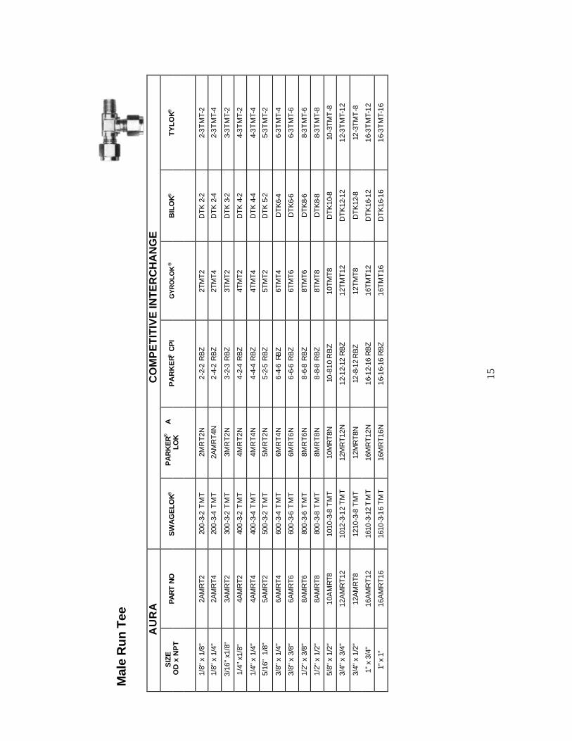
Mal
e R
un T
ee
A
UR
A
CO
MP
ET
ITIV
E IN
TE
RC
HA
NG
E
SIZ
E O
D x
NP
T PA
RT
NO
S
WA
GE
LOK®
P
AR
KE
R®
A
LOK
P
AR
KE
R® C
PI
GY
RO
LOK
®
BIL
OK®
T
YL
OK®
1/8"
x 1
/8"
2AM
RT2
20
0-3
-2 T
MT
2MR
T2N
2-
2-2
RB
Z 2T
MT2
D
TK 2
-2
2-3T
MT-
2
1/8"
x 1
/4"
2AM
RT4
20
0-3
-4 T
MT
2AM
RT4
N
2-4-
2 R
BZ
2TM
T4
DTK
2-4
2-
3TM
T-4
3/16
" x1
/8"
3AM
RT2
30
0-3
-2 T
MT
3MR
T2N
3-
2-3
RB
Z 3T
MT2
D
TK 3
-2
3-3T
MT-
2
1/4"
x1/
8"
4AM
RT2
40
0-3
-2 T
MT
4MR
T2N
4-
2-4
RB
Z 4T
MT2
D
TK 4
-2
4-3T
MT-
2
1/4"
x 1
/4"
4AM
RT4
40
0-3
-4 T
MT
4MR
T4N
4-
4-4
RB
Z 4T
MT4
D
TK 4
-4
4-3T
MT-
4
5/16
" 1
/8"
5AM
RT2
50
0-3
-2 T
MT
5MR
T2N
5-
2-5
RB
Z 5T
MT2
D
TK 5
-2
5-3T
MT-
2
3/8"
x 1
/4"
6AM
RT4
60
0-3
-4 T
MT
6MR
T4N
6-
4-6
RB
Z 6T
MT4
D
TK6-
4 6-
3TM
T-4
3/8"
x 3
/8"
6AM
RT6
60
0-3
-6 T
MT
6MR
T6N
6-
6-6
RB
Z 6T
MT6
D
TK6-
6 6-
3TM
T-6
1/2"
x 3
/8"
8AM
RT6
80
0-3
-6 T
MT
8MR
T6N
8-
6-8
RB
Z 8T
MT6
D
TK8-
6 8-
3TM
T-6
1/2"
x 1
/2"
8AM
RT8
80
0-3
-8 T
MT
8MR
T8N
8-
8-8
RB
Z 8T
MT8
D
TK8-
8 8-
3TM
T-8
5/8"
x 1
/2"
10A
MR
T8
1010
-3-8
TM
T
10M
RT8
N
10-8
10 R
BZ
10TM
T8
DT
K10
-8
10-3
TMT
-8
3/4"
x 3
/4"
12A
MR
T12
10
12-3
-12
TM
T
12M
RT1
2N
12-1
2-12
RB
Z
12T
MT
12
DT
K12
-12
12-3
TM
T-12
3/4"
x 1
/2"
12A
MR
T8
1210
-3-8
TM
T
12M
RT8
N
12-8
-12
RB
Z
12TM
T8
DT
K12
-8
12-3
TMT
-8
1” x
3/4
" 16
AM
RT
12
1610
-3-1
2 T
MT
16
MR
T12N
16
-12-
16 R
BZ
16
TM
T12
D
TK
16-1
2 16
-3T
MT-
12
1” x
1”
16
AM
RT
16
1610
-3-1
6 T
MT
16
MR
T16N
16
-16-
16 R
BZ
16
TM
T16
D
TK
16-1
6 16
-3T
MT-
16
15

AURA MALE BRANCH TEE
• INCH SIZE TUBING AURA ‘T’ ‘P’ A Ax B C D E Fx G H Hx Hy PART NO. TUBE OD NPT ~ A/F A/F 2AMBT2 1/8” 1/8” 1.84 1.84 0.38 0.60 0.50 0.09 7/16 7/16 1.32 0.66 0.69 2AMBT4 1/8” 1/4” 1.92 1.92 0.56 0.60 0.50 0.09 1/2 7/16 1.40 0.70 0.91 4AMBT2 1/4” 1/8" 2.10 2.10 0.38 0.70 0.60 0.19 1/2 9/16 1.52 0.76 0.73 4AMBT4 1/4" 1/4” 2.10 2.10 0.56 0.70 0.60 0.19 1/2 9/16 1.52 0.76 0.91 6AMBT4 3/8" 1/4” 2.38 2.38 0.56 0.76 0.66 0.28 5/8 11/16 1.80 0.90 0.99 6AMBT6 3/8” 3/8” 2.60 2.60 0.56 0.76 0.66 0.28 13/16 11/16 2.02 1.01 1.10 8AMBT6 1/2” 3/8” 2.82 2.82 0.56 0.86 0.90 0.38 13/16 7/8 2.02 1.01 1.10 8AMBT8 1/2” 1/2” 2.82 2.82 0.75 0.86 0.90 0.41 13/16 7/8 2.02 1.01 1.29
10AMBT8 5/8” 1/2” 3.04 3.04 0.75 0.86 0.96 0.47 1 1 2.24 1.12 1.40 12AMBT12 3/4” 3/4” 3.12 3.12 0.75 0.86 0.96 0.62 1-1/16 1-1/8 2.32 1.16 1.44 • METRIC SIZE TUBING AURA ‘T’ ‘P’ A Ax B C D E Fx G H Hx Hy PART NO. TUBE OD NPT ~ A/F A/F 6m AMBT2 6 1/8" 53.6 26.8 9.7 17.7 15.3 4.8 1/2 16 38.8 19.4 20.8 8m AMBT2 8 1/8” 59.4 29.7 9.7 18.6 16.2 4.8 5/8 16 44.4 22.2 20.8
10m AMBT4 10 1/4” 66.6 33.3 14.2 19.5 17.2 7.1 13/16 19 51.4 25.7 28.2 16m AMBT8 16 1/2” 77.2 38.6 19.0 22.0 24.4 11.9 1 25 57.0 28.5 35.8
-16-

Mal
e B
ranc
h Te
e
A
UR
A
CO
MP
ET
ITIV
E IN
TE
RC
HA
NG
E
SIZ
E O
D x
NP
T PA
RT
NO
S
WA
GE
LOK®
P
AR
KE
R®
A
LOK
P
AR
KE
R® C
PI
GY
RO
LOK
®
BIL
OK®
T
YL
OK®
1/8"
x 1
/8"
2AM
BT2
20
0-3
-2 T
TM
2M
BT
2N
2-2-
2 S
BZ
2TT
M2
DTN
2-2
2-
3-T
TM
-2
1/8"
x 1
/4"
2AM
BT4
20
0-3
-4 T
TM
2M
BT
4N
2-4-
2 S
BZ
2TT
M4
DTN
2-4
2-
3-T
TM
-4
3/16
" x1
/8"
3AM
BT2
30
0-3
-2 T
TM
3M
BT
2N
3-2-
3 S
BZ
3TT
M2
DTN
3-2
3-
3-T
TM
-2
1/4"
x1/
8"
4AM
BT2
40
0-3
-2 T
TM
4M
BT
2N
4-2-
4 S
BZ
4TT
M2
DTN
4-2
4-
3-T
TM
-2
1/4"
x 1
/4"
4AM
BT4
40
0-3
-4 T
TM
4M
BT
4N
4-4-
4 S
BZ
4TT
M4
DTN
4-4
4-
3-T
TM
-4
5/16
" 1
/8"
5AM
BT2
50
0-3
-2 T
TM
5M
BT
2N
5-2-
5 S
BZ
5TT
M2
DTN
5-2
5-
3-T
TM
-2
3/8"
x 1
/4"
6AM
BT4
60
0-3
-4 T
TM
6M
BT
4N
6-4-
6 S
BZ
6TT
M4
DTN
6-4
6-
3-T
TM
-4
3/8"
x 3
/8"
6AM
BT6
60
0-3
-6 T
TM
6M
BT
6N
6-6-
6 S
BZ
6TT
M6
DTN
6-6
6-
3-T
TM
-6
1/2"
x 3
/8"
8AM
BT6
80
0-3
-6 T
TM
8M
BT
6N
8-6-
8 S
BZ
8TT
M6
DTN
8-6
8-
3-T
TM
-6
1/2"
x 1
/2"
8AM
BT8
80
0-3
-8 T
TM
8M
BT
8N
8-8-
8 S
BZ
8TT
M8
DTN
8-8
8-
3-T
TM
-8
5/8"
x 1
/2"
10A
MB
T8
1010
-3-8
TT
M
10M
BT8
N
10-8
-10
SB
Z
10T
TM
8 D
TN 1
0-8
10-3
-TTM
-8
3/4"
x 3
/4"
12A
MB
T12
1210
-3-1
2 T
TM
12
MB
T12N
12
-12-
12 S
BZ
12
TT
M12
D
TN 1
2-12
12
-3-T
TM
-12
3/4"
x 1
/2"
12A
MB
T8
1210
-3-8
TT
M
12M
BT8
N
12-8
-12
SB
Z
12T
TM
8 D
TN 1
2-8
12-3
-TTM
-8
1” x
3/4
" 16
AM
BT1
2 16
10-3
-12
TT
M
16M
BT1
2N
16-1
2-16
SB
Z
16T
TM
12
DTN
16-
12
12-3
-TT
M-1
6
1” x
1”
16
AM
BT1
6 16
10-2
-16
TT
M
16M
BT1
6N
16-1
6-16
SB
Z
16T
TM
16
DTN
16-
16
16-3
-TT
M-1
6
17
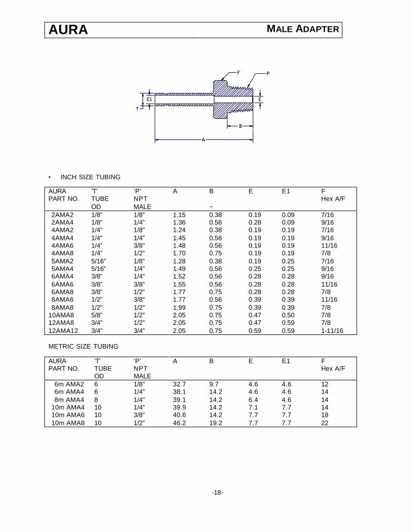
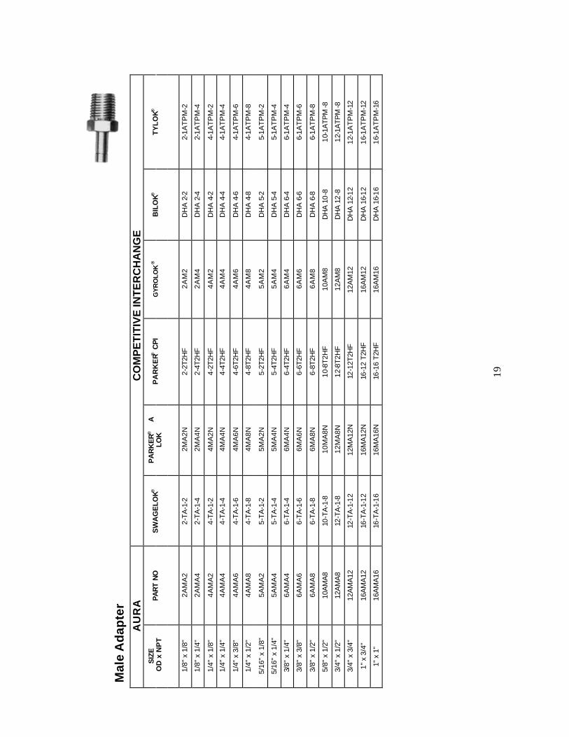
AURA MALE ADAPTER
• INCH SIZE TUBING AURA ‘T’ ‘P’ A B E E1 F PART NO. TUBE NPT Hex A/F OD MALE ~ 2AMA2 1/8” 1/8” 1.15 0.38 0.19 0.09 7/16 2AMA4 1/8” 1/4” 1.36 0.56 0.28 0.09 9/16 4AMA2 1/4” 1/8" 1.24 0.38 0.19 0.19 7/16 4AMA4 1/4" 1/4” 1.45 0.56 0.19 0.19 9/16 4AMA6 1/4” 3/8” 1.48 0.56 0.19 0.19 11/16 4AMA8 1/4” 1/2” 1.70 0.75 0.19 0.19 7/8 5AMA2 5/16” 1/8” 1.28 0.38 0.19 0.25 7/16 5AMA4 5/16” 1/4” 1.49 0.56 0.25 0.25 9/16 6AMA4 3/8" 1/4” 1.52 0.56 0.28 0.28 9/16 6AMA6 3/8” 3/8” 1.55 0.56 0.28 0.28 11/16 6AMA8 3/8” 1/2” 1.77 0.75 0.28 0.28 7/8 8AMA6 1/2” 3/8” 1.77 0.56 0.39 0.39 11/16 8AMA8 1/2” 1/2” 1.99 0.75 0.39 0.39 7/8
10AMA8 5/8” 1/2” 2.05 0.75 0.47 0.50 7/8 12AMA8 3/4” 1/2” 2.05 0.75 0.47 0.59 7/8 12AMA12 3/4” 3/4” 2.05 0.75 0.59 0.59 1-11/16 METRIC SIZE TUBING
AURA ‘T’ ‘P’ A B E E1 F PART NO. TUBE NPT Hex A/F OD MALE
6m AMA2 6 1/8" 32.7 9.7 4.6 4.6 12 6m AMA4 6 1/4” 38.1 14.2 4.6 4.6 14 8m AMA4 8 1/4” 39.1 14.2 6.4 4.6 14
10m AMA4 10 1/4” 39.9 14.2 7.1 7.7 14 10m AMA6 10 3/8” 40.6 14.2 7.7 7.7 18 10m AMA8 10 1/2” 46.2 19.2 7.7 7.7 22
-18-
Mal
e A
dap
ter
AU
RA
C
OM
PE
TIT
IVE
INT
ER
CH
AN
GE
S
IZE
OD
x N
PT
PAR
T N
O
SW
AG
ELO
K®
PA
RK
ER®
A
LO
K
PA
RK
ER®
CP
I G
YR
OLO
K®
BIL
OK®
T
YL
OK®
1/8"
x 1
/8"
2AM
A2
2-TA
-1-2
2M
A2N
2-
2T2H
F 2
AM
2 D
HA
2-2
2-
1AT
PM
-2
1/8"
x 1
/4"
2AM
A4
2-TA
-1-4
2M
A4N
2-
4T2H
F 2
AM
4 D
HA
2-4
2-
1AT
PM
-4
1/4"
x 1
/8"
4AM
A2
4-TA
-1-2
4M
A2N
4-
2T2H
F 4
AM
2 D
HA
4-2
4-
1AT
PM
-2
1/4"
x 1
/4"
4AM
A4
4-TA
-1-4
4M
A4N
4-
4T2H
F 4
AM
4 D
HA
4-4
4-
1AT
PM
-4
1/4"
x 3
/8"
4AM
A6
4-TA
-1-6
4M
A6N
4-
6T2H
F 4
AM
6 D
HA
4-6
4-
1AT
PM
-6
1/4"
x 1
/2"
4AM
A8
4-TA
-1-8
4M
A8N
4-
8T2H
F 4
AM
8 D
HA
4-8
4-
1AT
PM
-8
5/16
" x
1/8"
5A
MA
2 5-
TA-1
-2
5MA
2N
5-2T
2HF
5A
M2
DH
A 5
-2
5-1A
TP
M-2
5/16
" x
1/4"
5A
MA
4 5-
TA-1
-4
5MA
4N
5-4T
2HF
5A
M4
DH
A 5
-4
5-1A
TP
M-4
3/8"
x 1
/4"
6AM
A4
6-TA
-1-4
6M
A4N
6-
4T2H
F 6
AM
4 D
HA
6-4
6-
1AT
PM
-4
3/8"
x 3
/8"
6AM
A6
6-TA
-1-6
6M
A6N
6-
6T2H
F 6
AM
6 D
HA
6-6
6-
1AT
PM
-6
3/8"
x 1
/2"
6AM
A8
6-TA
-1-8
6M
A8N
6-
8T2H
F 6
AM
8 D
HA
6-8
6-
1AT
PM
-8
5/8"
x 1
/2"
10A
MA
8
10-T
A-1
-8
10M
A8N
10
-8T2
HF
10A
M8
DH
A 1
0-8
10
-1A
TPM
-8
3/4"
x 1
/2"
12A
MA
8
12-T
A-1
-8
12M
A8N
12
-8T2
HF
12A
M8
DH
A 1
2-8
12
-1A
TPM
-8
3/4"
x 3
/4"
12A
MA
12
12-T
A-1
-12
12M
A12
N
12-1
2T2H
F 12
AM
12
DH
A 1
2-12
12
-1A
TP
M-1
2
1" x
3/4
" 16
AM
A12
16
-TA
-1-1
2 16
MA
12N
16
-12
T2H
F 16
AM
12
DH
A 1
6-12
16
-1A
TP
M-1
2
1" x
1"
16A
MA
16
16-T
A-1
-16
16M
A16
N
16-1
6 T2
HF
16A
M16
D
HA
16-
16
16-1
AT
PM
-16
19
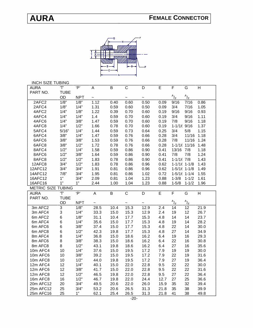
AURA FEMALE CONNECTOR
INCH SIZE TUBING AURA ‘T’ ‘P’ A B C D E F G H PART NO. TUBE OD NPT ~ ~ ~ A/F A/F
2AFC2 1/8” 1/8” 1.12 0.40 0.60 0.50 0.09 9/16 7/16 0.86 2AFC4 1/8” 1/4” 1.31 0.59 0.60 0.50 0.09 3/4 7/16 1.05 4AFC2 1/4” 1/8" 1.22 0.39 0.70 0.60 0.19 9/16 9/16 0.93 4AFC4 1/4” 1/4” 1.4 0.59 0.70 0.60 0.19 3/4 9/16 1.11 4AFC6 1/4” 3/8” 1.47 0.59 0.70 0.60 0.19 7/8 9/16 1.18 4AFC8 1/4” 1/2” 1.66 0.78 0.70 0.60 0.19 1-1/16 9/16 1.37 5AFC4 5/16” 1/4” 1.44 0.59 0.73 0.64 0.25 3/4 5/8 1.15 6AFC4 3/8" 1/4” 1.47 0.59 0.76 0.66 0.28 3/4 11/16 1.18 6AFC6 3/8” 3/8” 1.53 0.59 0.76 0.66 0.28 7/8 11/16 1.24 6AFC8 3/8" 1/2” 1.72 0.78 0.76 0.66 0.28 1-1/16 11/16 1.48 8AFC4 1/2” 1/4” 1.58 0.59 0.86 0.90 0.41 13/16 7/8 1.18 8AFC6 1/2” 3/8” 1.64 0.59 0.86 0.90 0.41 7/8 7/8 1.24 8AFC8 1/2” 1/2” 1.83 0.78 0.86 0.90 0.41 1-1/16 7/8 1.43
12AFC8 3/4” 1/2” 1.83 0.78 0.86 0.96 0.62 1-1/16 1-1/8 1.43 12AFC12 3/4” 3/4” 1.91 0.81 0.86 0.96 0.62 1-5/16 1-1/8 1.49 14AFC12 7/8” 3/4” 1.95 0.81 0.86 1.02 0.72 1-5/16 1-1/4 1.55 16AFC12 1” 3/4” 2.09 0.81 1.04 1.23 0.88 1-3/8 1-1/2 1.61 16AFC16 1” 1” 2.44 1.00 1.04 1.23 0.88 1-5/8 1-1/2 1.96 METRIC SIZE TUBING AURA ‘T’ ‘P’ A B C D E F G H PART NO. TUBE OD NPT ~ ~ ~ A/F A/F 3m AFC2 3 1/8” 28.5 10.4 15.3 12.9 2.4 14 12 21.9 3m AFC4 3 1/4” 33.3 15.0 15.3 12.9 2.4 19 12 26.7 6m AFC2 6 1/8" 31.1 10.4 17.7 15.3 4.8 14 14 23.7 6m AFC4 6 1/4” 35.6 15.0 17.7 15.3 4.8 19 14 28.2 6m AFC6 6 3/8” 37.4 15.0 17.7 15.3 4.8 22 14 30.0 6m AFC8 6 1/2” 42.3 19.8 17.7 15.3 4.8 27 14 34.9 8m AFC4 8 1/4” 36.8 15.0 18.6 16.2 6.4 19 16 29.3 8m AFC6 8 3/8” 38.3 15.0 18.6 16.2 6.4 22 16 30.8 8m AFC8 8 1/2” 43.1 19.8 18.6 16.2 6.4 27 16 35.6
10m AFC4 10 1/4” 37.6 15.0 19.5 17.2 7.9 19 19 30.0 10m AFC6 10 3/8” 39.2 15.0 19.5 17.2 7.9 22 19 31.6 10m AFC8 10 1/2” 44.0 19.8 19.5 17.2 7.9 27 19 36.4 12m AFC4 12 1/4” 40.1 15.0 22.0 22.8 9.5 22 22 30.0 12m AFC6 12 3/8” 41.7 15.0 22.0 22.8 9.5 22 22 31.6 12m AFC8 12 1/2” 46.5 19.8 22.0 22.8 9.5 27 22 36.4 16m AFC8 16 1/2” 46.7 19.8 22.0 24.4 12.7 27 25 36.6 20m AFC12 20 3/4” 49.5 20.6 22.0 26.0 15.9 35 32 39.4 25m AFC12 25 3/4” 53.2 20.6 26.5 31.3 21.8 35 38 39.9 25m AFC16 25 1” 62.1 25.4 26.5 31.3 21.8 41 38 49.8
-20-
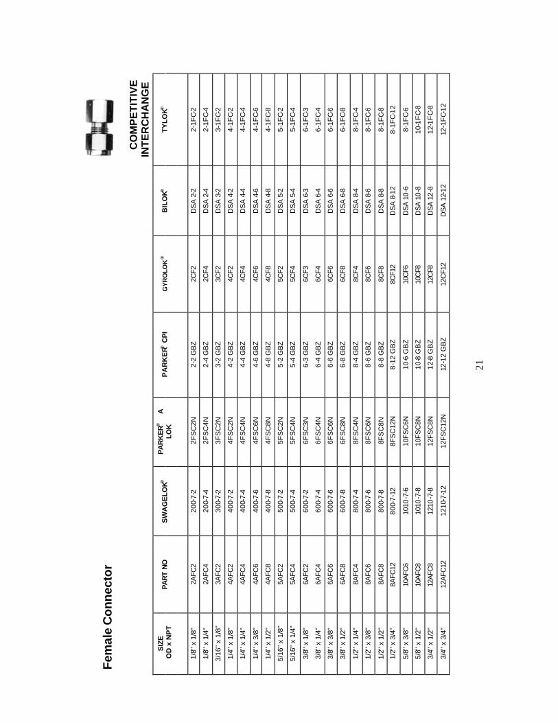
Fem
ale
Con
nect
or
CO
MP
ET
ITIV
E
INT
ER
CH
AN
GE
S
IZE
OD
x N
PT
PAR
T N
O
SW
AG
ELO
K®
PA
RK
ER®
A
LO
K
PA
RK
ER®
CP
I G
YR
OLO
K®
BIL
OK®
T
YL
OK®
1/8"
x 1
/8"
2AFC
2 20
0-7-
2 2F
SC
2N
2-2
GB
Z 2C
F2
DS
A 2
-2
2-1F
C-2
1/8"
x 1
/4"
2AFC
4 20
0-7-
4 2F
SC
4N
2-4
GB
Z 2C
F4
DS
A 2
-4
2-1F
C-4
3/16
" x
1/8"
3A
FC2
300-
7-2
3FS
C2N
3-
2 G
BZ
3CF2
D
SA
3-2
3-
1FC-
2
1/4"
x 1
/8"
4AFC
2 40
0-7-
2 4F
SC
2N
4-2
GB
Z 4C
F2
DS
A 4
-2
4-1F
C-2
1/4"
x 1
/4"
4AFC
4 40
0-7-
4 4F
SC
4N
4-4
GB
Z 4C
F4
DS
A 4
-4
4-1F
C-4
1/4"
x 3
/8"
4AFC
6 40
0-7-
6 4F
SC
6N
4-6
GB
Z 4C
F6
DS
A 4
-6
4-1F
C-6
1/4"
x 1
/2"
4AFC
8 40
0-7-
8 4F
SC
8N
4-8
GB
Z 4C
F8
DS
A 4
-8
4-1F
C-8
5/16
" x
1/8"
5A
FC2
500-
7-2
5FS
C2N
5-
2 G
BZ
5CF2
D
SA
5-2
5-
1FC-
2
5/16
" x
1/4"
5A
FC4
500-
7-4
5FS
C4N
5-
4 G
BZ
5CF4
D
SA
5-4
5-
1FC-
4
3/8"
x 1
/8"
6AFC
2 60
0-7-
2 6F
SC
3N
6-3
GB
Z 6C
F3
DS
A 6
-3
6-1F
C-3
3/8"
x 1
/4"
6AFC
4 60
0-7-
4 6F
SC
4N
6-4
GB
Z 6C
F4
DS
A 6
-4
6-1F
C-4
3/8"
x 3
/8"
6AFC
6 60
0-7-
6 6F
SC
6N
6-6
GB
Z 6C
F6
DS
A 6
-6
6-1F
C-6
3/8"
x 1
/2"
6AFC
8 60
0-7-
8 6F
SC
8N
6-8
GB
Z 6C
F8
DS
A 6
-8
6-1F
C-8
1/2"
x 1
/4"
8AFC
4 80
0-7-
4 8F
SC
4N
8-4
GB
Z 8C
F4
DS
A 8
-4
8-1F
C-4
1/2"
x 3
/8"
8AFC
6 80
0-7-
6 8F
SC
6N
8-6
GB
Z 8C
F6
DS
A 8
-6
8-1F
C-6
1/2"
x 1
/2"
8AFC
8 80
0-7-
8 8F
SC
8N
8-8
GB
Z 8C
F8
DS
A 8
-8
8-1F
C-8
1/2"
x 3
/4"
8AFC
12
800-
7-12
8F
SC
12N
8-
12 G
BZ
8CF1
2 D
SA
8-1
2 8-
1FC
-12
5/8"
x 3
/8"
10AF
C6
10
10-7
-6
10FS
C6N
10
-6 G
BZ
10C
F6
DS
A 1
0-6
8-1F
C-6
5/8"
x 1
/2"
10AF
C8
10
10-7
-8
10FS
C8N
10
-8 G
BZ
10C
F8
DS
A 1
0-8
10-1
FC-
8
3/4"
x 1
/2"
12AF
C8
12
10-7
-8
12FS
C8N
12
-8 G
BZ
12C
F8
DS
A 1
2-8
12-1
FC-
8
3/4"
x 3
/4"
12A
FC12
12
10-7
-12
12FS
C12
N
12-1
2 G
BZ
12C
F12
D
SA
12-
12
12-1
FC-
12
21
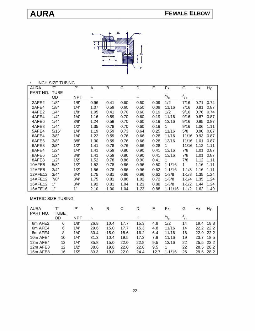
AURA FEMALE ELBOW
• INCH SIZE TUBING AURA ‘T’ ‘P’ A B C D E Fx G Hx Hy PART NO. TUBE OD NPT ~ ~ A/F A/F 2AFE2 1/8” 1/8” 0.96 0.41 0.60 0.50 0.09 1/2 7/16 0.71 0.74 2AFE4 1/8” 1/4” 1.07 0.59 0.60 0.50 0.09 11/16 7/16 0.81 0.87 4AFE2 1/4” 1/8" 1.05 0.41 0.70 0.60 0.19 1/2 9/16 0.76 0.74 4AFE4 1/4” 1/4” 1.16 0.59 0.70 0.60 0.19 11/16 9/16 0.87 0.87 4AFE6 1/4” 3/8” 1.24 0.59 0.70 0.60 0.19 13/16 9/16 0.95 0.87 4AFE8 1/4” 1/2” 1.35 0.78 0.70 0.60 0.19 1 9/16 1.06 1.11 5AFE4 5/16” 1/4” 1.19 0.59 0.73 0.64 0.25 11/16 5/8 0.90 0.87 6AFE4 3/8" 1/4” 1.22 0.59 0.76 0.66 0.28 11/16 11/16 0.93 0.87 6AFE6 3/8” 3/8” 1.30 0.59 0.76 0.66 0.28 13/16 11/16 1.01 0.87 6AFE8 3/8" 1/2” 1.41 0.78 0.76 0.66 0.28 1 11/16 1.12 1.11 8AFE4 1/2” 1/4” 1.41 0.59 0.86 0.90 0.41 13/16 7/8 1.01 0.87 8AFE6 1/2” 3/8” 1.41 0.59 0.86 0.90 0.41 13/16 7/8 1.01 0.87 8AFE8 1/2” 1/2" 1.52 0.78 0.86 0.90 0.41 1 7/8 1.12 1.11
10AFE8 5/8” 1/2” 1.52 0.78 0.86 0.96 0.50 1-1/16 1 1.16 1.11 12AFE8 3/4” 1/2” 1.56 0.78 0.86 0.96 0.62 1-1/16 1-1/8 1.16 1.11 12AFE12 3/4” 3/4” 1.75 0.81 0.86 0.96 0.62 1-3/8 1-1/8 1.35 1.24 14AFE12 7/8” 3/4” 1.75 0.81 0.86 1.02 0.72 1-3/8 1-1/4 1.35 1.24 16AFE12 1” 3/4” 1.92 0.81 1.04 1.23 0.88 1-3/8 1-1/2 1.44 1.24 16AFE16 1” 1” 2.10 1.00 1.04 1.23 0.88 1-11/16 1-1/2 1.62 1.49 METRIC SIZE TUBING AURA ‘T’ ‘P’ A B C D E Fx G Hx Hy PART NO. TUBE OD NPT ~ ~ A/F A/F 6m AFE2 6 1/8" 26.8 10.4 17.7 15.3 4.8 1/2 14 19.4 18.8 6m AFE4 6 1/4” 29.6 15.0 17.7 15.3 4.8 11/16 14 22.2 22.2 8m AFE4 8 1/4” 30.4 15.0 18.6 16.2 6.4 11/16 16 22.9 22.2
10m AFE4 10 1/4” 31.3 10.4 19.5 17.2 7.9 11/16 19 23.7 18.5 12m AFE4 12 1/4” 35.8 15.0 22.0 22.8 9.5 13/16 22 25.5 22.2 12m AFE8 12 1/2” 38.6 19.8 22.0 22.8 9.5 1 22 28.5 28.2 16m AFE8 16 1/2” 39.3 19.8 22.0 24.4 12.7 1-1/16 25 29.5 28.2
-22-

Fem
ale
Elb
ow
A
UR
A
C
OM
PE
TIT
IVE
INT
ER
CH
AN
GE
S
IZE
OD
x N
PT
PA
RT
NO
S
WA
GE
LOK
®
PA
RK
ER®
A
LO
K
PA
RK
ER
® C
PI
GY
RO
LOK
®
BIL
OK®
TY
LOK
®
1/8"
x 1
/8"
2AFE
2 20
0-8-
2 2F
EL2
N 2-
2 D
BZ
2LF2
D
LF 2
-2
2-2F
E-2
1/8"
x 1
/4"
2AFE
4 20
0-8-
4 2F
EL4
N 2-
4 D
BZ
2LF4
D
LF 2
-4
2-2F
E-4
3/16
" x
1/8"
3A
FE2
300-
8-2
3FE
L2N
3-2
DB
Z 3L
F2
DLF
3-2
3-
2FE
-2
1/4"
x 1
/8"
4AFE
2 40
0-8-
2 4F
EL2
N 4-
2 D
BZ
4LF2
D
LF 4
-2
4-2F
E-2
1/4"
x 1
/4"
4AFE
4 40
0-8-
4 4F
EL4
N 4-
4 D
BZ
4LF4
D
LF 4
-4
4-2F
E-4
1/4"
x 3
/8"
4AFE
6 40
0-8-
6 4F
EL6
N 4-
6 D
BZ
4LF6
D
LF 4
-6
4-2F
E-6
1/4"
x 1
/2"
4AFE
8 40
0-8-
8 4F
EL8
N 4-
8 D
BZ
4LF8
D
LF 4
-8
4-2F
E-8
5/16
" x
1/4"
5A
FE4
500-
8-4
5FE
L4N
5-4
DB
Z 5L
F4
DLF
5-4
5-
2FE
-4
3/8"
x 1
/4"
6AFE
4 60
0-8-
4 6F
EL4
N 6-
4 D
BZ
6LF4
D
LF 6
-4
6-2F
E-4
3/8"
x 3
/8"
6AFE
6 60
0-8-
6 6F
EL6
N 6-
6 D
BZ
6LF6
D
LF 6
-6
6-2F
E-6
1/2"
x 1
/4"
8AF
E4
810-
8-4
8FE
L4N
8-4
DB
Z 8L
F4
DLF
8-4
8-
2FE
-4
1/2"
x 3
/8"
8AFE
6 81
0-8-
6 8F
EL6
N 8-
6 D
BZ
8LF6
D
LF 8
-6
8-2F
E-6
1/2"
x 1
/2"
8AFE
8 81
0-8-
8 8F
EL8
N 8-
8 D
BZ
8LF8
D
LF 8
-8
8-2F
E-8
5/8"
x 1
/2"
10A
FE8
10
10-8
-8
10FE
L8N
10-8
DB
Z 10
LF8
DLF
10-
8 10
-2FE
-8
3/4"
x 1
/2"
12A
FE8
12
10-8
-8
12FE
L8N
12-8
DB
Z 12
LF8
DLF
12-
8 12
-2FE
-8
3/4"
x 3
/4"
12A
FE12
12
10-8
-12
12F
EL1
2N
12-1
2 D
BZ
12LF
12
DLF
12
-12
12-2
FE
-12
3/4"
x 1
" 12
AFE
16
1210
-8-1
6 12
FE
L16N
12
-16
DB
Z 12
LF16
D
LF 1
2-1
6 12
-2F
E-1
6
1" x
3/4
" 16
AFE
12
1610
-8-1
2 16
FE
L12N
16
-12
DB
Z 16
LF12
D
LF16
-12
16-2
FE
-12
1" x
1"
16A
FE16
16
10-8
-16
16F
EL1
6N
16-1
6 D
BZ
16LF
16
DLF
16
-16
16-2
FE
-16
23

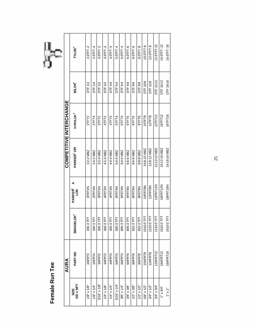
AURA FEMALE RUN TEE
• INCH SIZE TUBING
AURA ‘T’ ‘P’ A Ax B C D E Fx G H Hx Hy PART NO. TUBE OD NPT ~ ~ A/F A/F 2AFRT2 1/8” 1/8” 1.71 0.96 0.41 0.60 0.50 0.09 1/2 7/16 1.44 0.70 0.74 4AFRT2 1/4” 1/8" 1.81 1.05 0.41 0.70 0.60 0.19 1/2 9/16 1.50 0.76 0.74 4AFRT4 1/4” 1/4” 2.05 1.16 0.59 0.70 0.60 0.19 11/16 9/16 1.79 0.87 0.87 6AFRT4 3/8’ 1/4” 2.10 1.22 0.59 0.76 0.66 0.28 11/16 11/16 1.79 0.93 0.87 8AFRT6 1/2” 3/8” 2.29 1.41 0.59 0.86 0.90 0.41 13/16 7/8 1.88 1.01 0.87 8AFRT8 1/2" 1/2” 2.68 1.56 0.78 0.86 0.90 0.41 1-1/16 7/8 2.27 1.16 1.12
12AFRT12 3/4” 3/4” 3.00 1.75 0.81 0.86 0.96 0.62 1-3/8 1-1/8 2.59 1.35 1.24 16AFRT12 1” 3/4” 3.17 1.92 0.81 1.04 1.23 0.88 1-3/8 1-1/2 2.68 1.44 1.24 16AFRT16 1” 1” 3.60 2.10 1.00 1.04 1.23 0.88 1-11/16 1-1/2 3.11 1.62 1.49 METRIC SIZE TUBING AURA ‘T’ ‘P’ A Ax B C D E Fx G H Hx Hy PART NO. TUBE OD NPT ~ ~ A/F A/F 6m AFRT2 6 1/8" 45.6 26.8 10.4 17.7 15.3 4.8 1/2 14 38.2 19.4 18.8 6m AFRT4 6 1/4” 51.8 29.6 15.0 17.7 15.3 4.8 11/16 14 44.4 22.2 22.2 8m AFRT2 8 1/8” 48.5 29.7 10.4 18.6 16.2 6.4 5/8 16 41.0 22.2 18.8 8m AFRT4 8 1/4” 52.6 30.4 15.0 18.6 16.2 6.4 11/16 16 45.1 22.9 22.2
10m AFRT4 10 1/4” 55.5 33.3 15.0 19.5 17.2 7.9 13/16 19 47.9 25.7 22.2 12m AFRT6 12 3/8” 58.0 35.8 15.0 22.0 22.8 10.3 13/16 22 47.9 25.7 22.2 12m AFRT8 12 1/2” 58.0 35.8 15.0 22.0 22.8 9.5 13/16 22 47.9 25.7 22.2 16m AFRT8 16 1/2” 67.8 39.6 19.8 22.0 24.4 12.7 1-1/16 25 57.7 29.5 28.2
-24-
Fem
ale
Ru
n T
ee
AU
RA
C
OM
PE
TIT
IVE
INT
ER
CH
AN
GE
S
IZE
OD
x N
PT
PA
RT
NO
SW
AG
ELO
K®
PA
RK
ER®
A
LO
K
PA
RK
ER
® C
PI
GY
RO
LOK
®
BIL
OK®
TY
LOK
®
1/8"
x 1
/8"
2AFR
T2
200
-3 T
FT
2FR
T2N
2-2-
2 M
BZ
2TF
T2
DTF
2-2
2-
3TFT
-2
1/8"
x 1
/4"
2AFR
T4
200
-3 T
FT
2FR
T4N
2-4-
2 M
BZ
2TF
T4
DTF
2-4
2-
3TFT
-4
3/16
" x
1/8"
3A
FRT2
30
0-3
TFT
3F
RT2
N 3-
2-3
MB
Z 3T
FT
2 D
TF 3
-2
3-3T
FT-2
1/4"
x 1
/8"
4AFR
T2
400
-3 T
FT
4FR
T2N
4-2-
4 M
BZ
4TF
T2
DTF
4-2
4-
3TFT
-2
1/4"
x 1
/4"
4AFR
T4
400
-3 T
FT
4FR
T4N
4-4-
4 M
BZ
4TF
T4
DTF
4-4
4-
3TFT
-4
5/16
" x
1/4"
5A
FRT4
50
0-3
TFT
5F
RT4
N 5-
4-5
MB
Z 5T
FT
4 D
TF 5
-4
5-3T
FT-4
3/8"
x 1
/4"
6AFR
T4
600
-3 T
FT
6FR
T4N
6-4-
6 M
BZ
6TF
T4
DTF
6-4
6-
3TFT
-4
3/8"
x 3
/8"
6AFR
T6
600
-3 T
FT
6FR
T6N
6-6-
6 M
BZ
6TF
T6
DTF
6-6
6-
3TFT
-6
1/2"
x 3
/8"
8AFR
T6
810
-3 T
FT
8FR
T6N
8-6-
8 M
BZ
8TF
T6
DTF
8-6
8-
3TFT
-6
1/2"
x 1
/2"
8AFR
T8
810
-3 T
FT
8FR
T8N
8-8-
8 M
BZ
8TF
T8
DTF
8-8
8-
3TFT
-8
5/8"
x 1
/2"
10A
FRT8
10
10-3
TFT
10
FRT8
N 10
-8-1
0 M
BZ
10TF
T8
DTF
10-
8 10
-3TF
T-8
3/4"
x 1
/2"
12A
FRT8
12
10-3
TFT
12
FRT8
N 12
-8-1
2 M
BZ
12TF
T8
DTF
12-
8 12
-3TF
T-8
3/4"
x 3
/4"
12A
FRT1
2 12
10-3
TFT
12
FRT1
2N
12-1
2-12
MB
Z
12TF
T12
D
TF 1
2-12
12
-3T
FT-1
2
1" x
3/4
" 16
AFR
T12
1610
-3 T
FT
16FR
T12N
16
-12-
16 M
BZ
16
TFT1
2
DTF
16-
12
16-3
TFT
-12
1" x
1"
16A
FRT1
6 16
10-3
TFT
16
FRT1
6N
16-1
6-16
MB
Z
16TF
T16
D
TF 1
6-16
16
-3TF
T-1
6
25

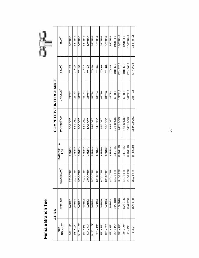
AURA FEMALE BRANCH TEE
• INCH SIZE TUBING AURA ‘T’ ‘P’ A Ax B C D E Fx G H Hx Hy PART NO. TUBE OD NPT ~ ~ A/F A/F 2AFBT2 1/8” 1/8” 1.92 0.96 0.41 0.60 0.50 0.09 1/2 7/16 1.40 0.70 0.74 4AFBT2 1/4” 1/8” 2.10 1.05 0.41 0.70 0.60 0.19 1/2 9/16 1.52 0.76 0.74 4AFBT4 1/4" 1/4” 2.32 1.16 0.59 0.70 0.60 0.19 11/16 9/16 1.74 0.87 0.87 6AFBT4 3/8" 1/4” 2.44 1.22 0.59 0.76 0.66 0.28 11/16 11/16 1.84 0.93 0.87 6AFBT6 3/8” 3/8” 2.60 1.30 0.59 0.76 0.66 0.28 13/16 11/16 2.02 1.01 0.87 8AFBT6 1/2” 3/8” 2.82 1.41 0.59 0.86 0.90 0.41 13/16 7/8 2.02 1.01 0.87 8AFBT8 1/2” 1/2” 3.04 1.52 0.78 0.86 0.90 0.41 1 7/8 2.24 1.12 1.11
10AFBT8 5/8” 1/2” 3.04 1.52 0.78 0.86 0.96 0.50 1 1 2.24 1.12 1.11 12AFBT12 3/4” 3/4” 3.50 1.75 0.81 0.86 0.96 0.62 1-3/8 1-1/8 2.70 1.35 1.24 16AFBT12 1” 3/4” 3.84 1.92 0.81 1.04 1.23 0.88 1-3/8 1-1/2 2.88 1.44 1.24 16AFBT16 1” 1” 4.20 2.10 1.00 1.04 1.23 0.88 1-11/16 1-1/2 3.24 1.62 1.49 • METRIC SIZE TUBING AURA ‘T’ ‘P’ A Ax B C D E Fx G H Hx Hy PART NO. TUBE OD NPT ~ ~ A/F A/F 6m AFBT2 6 1/8" 53.6 26.8 10.4 17.7 15.3 4.8 1/2 14 38.8 19.4 18.8 6m AFBT4 6 1/4” 59.2 29.6 15.0 17.7 15.3 4.8 11/16 14 44.4 22.2 22.2 8m AFBT2 8 1/8” 59.4 29.7 10.4 18.6 16.2 6.4 5/8 16 44.4 22.2 18.8 8m AFBT4 8 1/4” 60.8 30.4 15.0 18.6 16.2 6.4 11/16 16 45.8 22.9 22.2
10m AFBT4 10 1/4” 66.6 33.3 15.0 19.5 17.2 7.9 13/16 19 51.4 25.7 22.2 12m AFBT4 12 3/8” 71.6 35.8 15.0 22.0 22.8 9.5 13/16 22 51.4 25.7 22.2 12m AFBT6 12 1/4” 71.6 35.8 15.0 22.0 22.8 9.5 13/16 22 51.4 25.7 22.2 16m AFBT8 16 1/2” 77.2 38.6 19.8 22.0 24.4 12.7 1 25 57.0 28.5 22.2
-26-
Fem
ale
Bra
nch
Tee
A
UR
A
C
OM
PE
TIT
IVE
INT
ER
CH
AN
GE
S
IZE
OD
x N
PT
PA
RT
NO
S
WA
GE
LOK
®
PA
RK
ER®
A
LO
K
PA
RK
ER
® C
PI
GY
RO
LOK
®
BIL
OK®
TY
LOK
®
1/8"
x 1/
8"
2AFB
T2
200
-3 T
TF
2FB
T2N
2-2-
2 O
BZ
2TTF
2 D
TH 2
-2
2-3T
TF
-2
1/8”
X 1
/4"
2AFB
T4
200-
3 TT
F 2F
BT4
N 2-
4-2
OB
Z 2T
TF4
DTH
2-4
2-
3TT
F-4
3/16
” x
1/8”
3A
FBT2
30
0-3
TTF
3F
BT2
N 3-
2-3
OB
Z 3T
TF2
DTH
3-2
3-
3TT
F-2
1/4"
x 1
/8"
4AFB
T2
400
-3 T
TF
4FB
T4N
4-4-
4 O
BZ
4TTF
4 D
TH 4
-4
4-3T
TF
-4
1/4"
x 1
/4”
4AFB
T4
400
-3 T
TF
4FB
T2N
4-2-
4 O
BZ
4TTF
2 D
TH 4
-2
4-3T
TF
-2
5/16
” x
1/4"
5A
FBT4
50
0-3
TTF
5F
BT4
N 5-
4-5
OB
Z 5T
TF4
DTH
5-4
5-
3TT
F-4
3/8"
x 1
/4"
6AFB
T4
600
-3 T
TF
6FB
T4N
6-4-
6 O
BZ
6TTF
4 D
TH 6
-4
6-3T
TF
-4
3/8"
x 3
/8"
6AFB
T6
600
-3 T
TF
6FB
T6N
6-6-
6 O
BZ
6TTF
6 D
TH 6
-6
6-3T
TF
-6
1/2"
x 3
/8"
8AFB
T6
800
-3 T
TF
8FB
T6N
8-6-
8 O
BZ
8TTF
6 D
TH 8
-6
8-3T
TF
-6
1/2"
x 1
/2"
8AFB
T8
810
-3 T
TF
8FB
T8N
8-8-
8 O
BZ
8TTF
8 D
TH 8
-8
8-3T
TF
-8
5/8"
x 1
/2"
10A
FBT8
10
10-3
TT
F 10
FB
T8N
10
-8-1
0 O
BZ
10TT
F8
DTH
10-
8 10
-3T
TF-
8
3/4"
x 1
/2"
12A
FBT8
12
10-3
TT
F 12
FB
T12
N 12
-12-
12 O
BZ
12
TTF1
2
DTH
12-
12
12-3
TT
F-1
2
3/4"
x 3
/4"
12A
FBT1
2 12
10-3
TT
F 12
FB
T8N
12
-8-1
2 O
BZ
12TT
F8
DTH
12-
8 12
-3T
TF-
8
1" x
3/4
" 16
AFB
T12
1610
-3 T
TF
16F
BT
12N
16-1
2-16
OB
Z
16TT
F12
D
TH 1
6-12
16
-3T
TF
-12
1" x
1"
16A
FBT1
6 16
10-3
TT
F 16
FB
T16
N 16
-16-
16 O
BZ
16
TTF1
6
DTH
16-
16
16-3
TT
F-1
6
27
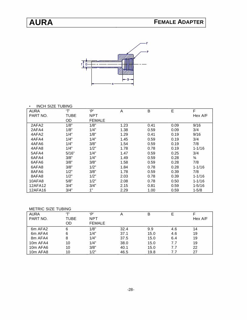
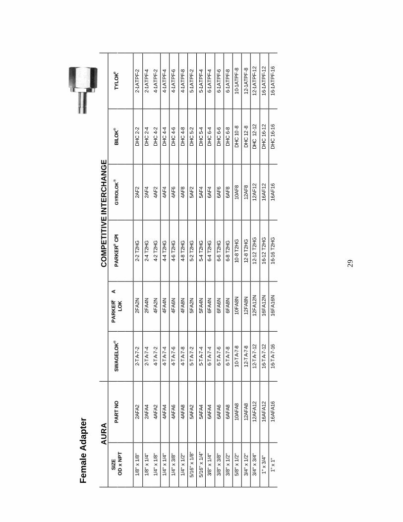
AURA FEMALE ADAPTER
• INCH SIZE TUBING AURA ‘T’ ‘P’ A B E F PART NO. TUBE NPT Hex A/F OD FEMALE 2AFA2 1/8” 1/8” 1.23 0.41 0.09 9/16 2AFA4 1/8” 1/4” 1.38 0.59 0.09 3/4 4AFA2 1/4” 1/8" 1.29 0.41 0.19 9/16 4AFA4 1/4" 1/4” 1.45 0.59 0.19 3/4 4AFA6 1/4” 3/8” 1.54 0.59 0.19 7/8 4AFA8 1/4” 1/2” 1.78 0.78 0.19 1-1/16 5AFA4 5/16” 1/4” 1.47 0.59 0.25 3/4 6AFA4 3/8” 1/4” 1.49 0.59 0.28 ¾ 6AFA6 3/8” 3/8” 1.58 0.59 0.28 7/8 6AFA8 3/8” 1/2” 1.84 0.78 0.28 1-1/16 8AFA6 1/2” 3/8” 1.78 0.59 0.39 7/8 8AFA8 1/2” 1/2” 2.03 0.78 0.39 1-1/16
10AFA8 5/8” 1/2” 2.08 0.78 0.50 1-1/16 12AFA12 3/4” 3/4” 2.15 0.81 0.59 1-5/16 12AFA16 3/4” 1” 2.29 1.00 0.59 1-5/8 METRIC SIZE TUBING AURA ‘T’ ‘P’ A B E F PART NO. TUBE NPT Hex A/F OD FEMALE 6m AFA2 6 1/8" 32.4 9.9 4.6 14 6m AFA4 6 1/4” 37.1 15.0 4.6 19 8m AFA4 8 1/4” 37.5 15.0 6.4 19
10m AFA4 10 1/4” 38.0 15.0 7.7 19 10m AFA6 10 3/8” 40.1 15.0 7.7 22 10m AFA8 10 1/2” 46.5 19.8 7.7 27
-28-
Fem
ale
Ad
apte
r
A
UR
A
C
OM
PE
TIT
IVE
INT
ER
CH
AN
GE
S
IZE
OD
x N
PT
PA
RT
NO
S
WA
GE
LOK
®
PA
RK
ER®
A
LO
K
PA
RK
ER
® C
PI
GY
RO
LOK
®
BIL
OK
®
TYLO
K®
1/8"
x 1
/8"
2AFA
2 2-
TA-
7-2
2FA
2N
2-2
T2H
G
2AF2
D
HC
2-2
2-
1AT
PF-
2
1/8"
x 1
/4"
2AFA
4 2-
TA-
7-4
2FA
4N
2-4
T2H
G
2AF4
D
HC
2-4
2-
1AT
PF-
4
1/4"
x 1
/8"
4AFA
2 4-
TA-
7-2
4FA
2N
4-2
T2H
G
4AF2
D
HC
4-2
4-
1AT
PF-
2
1/4"
x 1
/4"
4AFA
4 4-
TA-
7-4
4FA
4N
4-4
T2H
G
4AF4
D
HC
4-4
4-
1AT
PF-
4
1/4"
x 3
/8"
4AFA
6 4-
TA-
7-6
4FA
6N
4-6
T2H
G
4AF6
D
HC
4-6
4-
1AT
PF-
6
1/4"
x 1
/2"
4AFA
8 4-
TA-
7-8
4FA
8N
4-8
T2H
G
4AF8
D
HC
4-8
4-
1AT
PF-
8
5/16
" x
1/8"
5A
FA2
5-T
A-7-
2 5F
A2N
5-
2 T2
HG
5A
F2
DH
C 5
-2
5-1A
TP
F-2
5/16
" x
1/4"
5A
FA4
5-T
A-7-
4 5F
A4N
5-
4 T2
HG
5A
F4
DH
C 5
-4
5-1A
TP
F-4
3/8"
x 1
/4"
6AFA
4 6-
TA-
7-4
6FA
4N
6-4
T2H
G
6AF4
D
HC
6-4
6-
1AT
PF-
4
3/8"
x 3
/8"
6AFA
6 6-
TA-
7-6
6FA
6N
6-6
T2H
G
6AF6
D
HC
6-6
6-
1AT
PF-
6
3/8"
x 1
/2"
6AFA
8 6-
TA-
7-8
6FA
8N
6-8
T2H
G
6AF8
D
HC
6-8
6-
1AT
PF-
8
5/8"
x 1
/2"
10A
FA8
10
-TA-
7-8
10FA
8N
10-8
T2H
G
10A
F8
DH
C 1
0-8
10
-1A
TPF
-8
3/4"
x 1
/2"
12A
FA8
12
-TA-
7-8
12FA
8N
12-8
T2H
G
12A
F8
DH
C 1
2-8
12
-1A
TPF
-8
3/4"
x 3
/4"
12A
FA12
12
-TA-
7-12
12
FA12
N 12
-12
T2H
G
12A
F12
D
HC
12-
12
12-1
AT
PF-
12
1" x
3/4
" 16
AFA
12
16-T
A-7-
12
16FA
12N
16-1
2 T2
HG
16
AF
12
DH
C 1
6-12
16
-1A
TP
F-12
1" x
1"
16A
FA16
16
-TA-
7-16
16
FA16
N 16
-16
T2H
G
16A
F16
D
HC
16-
16
16-1
AT
PF-
16
29
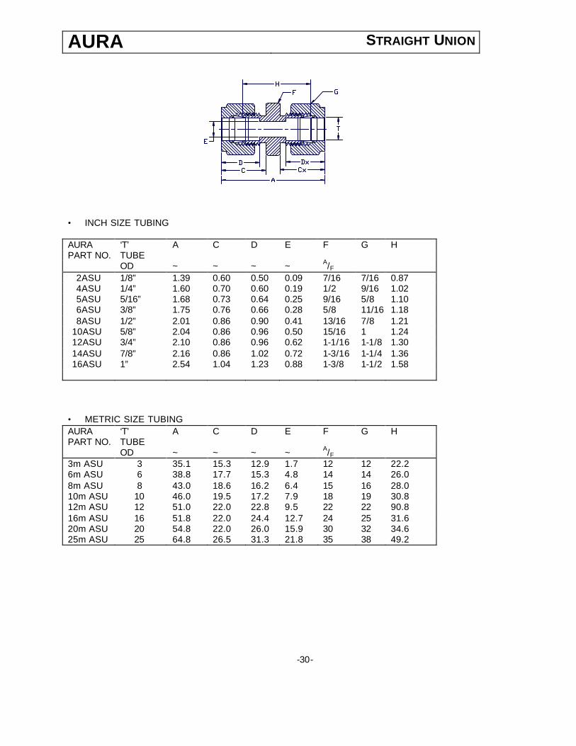
AURA STRAIGHT UNION
• INCH SIZE TUBING AURA ‘T’ A C D E F G H PART NO. TUBE OD ~ ~ ~ ~ A/F
2ASU 1/8” 1.39 0.60 0.50 0.09 7/16 7/16 0.87 4ASU 1/4” 1.60 0.70 0.60 0.19 1/2 9/16 1.02 5ASU 5/16” 1.68 0.73 0.64 0.25 9/16 5/8 1.10 6ASU 3/8” 1.75 0.76 0.66 0.28 5/8 11/16 1.18 8ASU 1/2” 2.01 0.86 0.90 0.41 13/16 7/8 1.21
10ASU 5/8” 2.04 0.86 0.96 0.50 15/16 1 1.24 12ASU 3/4” 2.10 0.86 0.96 0.62 1-1/16 1-1/8 1.30 14ASU 7/8” 2.16 0.86 1.02 0.72 1-3/16 1-1/4 1.36 16ASU 1” 2.54 1.04 1.23 0.88 1-3/8 1-1/2 1.58
• METRIC SIZE TUBING AURA ‘T’ A C D E F G H PART NO. TUBE OD ~ ~ ~ ~ A/F 3m ASU 3 35.1 15.3 12.9 1.7 12 12 22.2 6m ASU 6 38.8 17.7 15.3 4.8 14 14 26.0 8m ASU 8 43.0 18.6 16.2 6.4 15 16 28.0 10m ASU 10 46.0 19.5 17.2 7.9 18 19 30.8 12m ASU 12 51.0 22.0 22.8 9.5 22 22 90.8 16m ASU 16 51.8 22.0 24.4 12.7 24 25 31.6 20m ASU 20 54.8 22.0 26.0 15.9 30 32 34.6 25m ASU 25 64.8 26.5 31.3 21.8 35 38 49.2
-30-
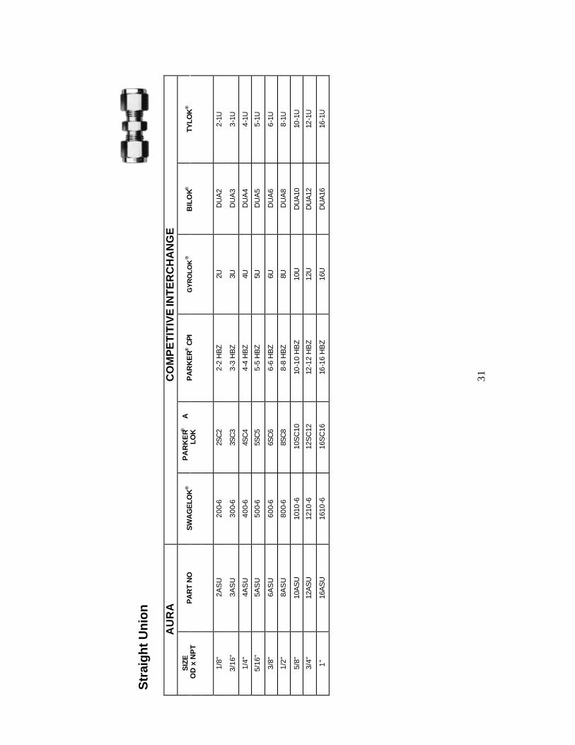
Str
aigh
t U
nion
AU
RA
CO
MP
ET
ITIV
E IN
TE
RC
HA
NG
E
SIZ
E O
D x
NP
T P
AR
T N
O
SW
AG
ELO
K®
PA
RK
ER®
A
LO
K
PA
RK
ER
® C
PI
GY
RO
LOK
®
BIL
OK®
TY
LOK
®
1/8"
2A
SU
200-
6 2S
C2
2-
2 H
BZ
2U
DU
A2
2-1U
3/16
" 3A
SU
300-
6 3S
C3
3-
3 H
BZ
3U
DU
A3
3-1U
1/4"
4A
SU
400-
6 4S
C4
4-
4 H
BZ
4U
DU
A4
4-1U
5/16
" 5A
SU
500-
6 5S
C5
5-
5 H
BZ
5U
DU
A5
5-1U
3/8"
6A
SU
600-
6 6S
C6
6-
6 H
BZ
6U
DU
A6
6-1U
1/2"
8A
SU
800-
6 8S
C8
8-
8 H
BZ
8U
DU
A8
8-1U
5/8"
10
AS
U
1010
-6
10S
C10
10
-10
HB
Z 10
U
DU
A10
10
-1U
3/4"
12
AS
U
1210
-6
12S
C12
12
-12
HB
Z 12
U
DU
A12
12
-1U
1”
16A
SU
16
10-6
16
SC
16
16-1
6 H
BZ
16U
D
UA
16
16-1
U
31

AURA BULKHEAD UNION
• INCH SIZE TUBING AURA ‘T’ A Ax C D E F G H Hx PANEL MAX. PART NO. TUBE HOLE PANEL OD ~ ~ ~ ~ A/F A/F DRILL THICKNESS SIZE 2ABHU 1/8” 2.01 1.22 0.60 0.50 0.09 1/2 7/16 1.49 0.96 21/64 0.50 4ABHU 1/4” 2.26 1.31 0.70 0.60 0.19 5/8 9/16 1.68 1.02 29/64 0.40 5ABHU 5/16” 2.38 1.40 0.73 0.64 0.25 11/16 5/8 1.80 1.11 33/64 0.44 6ABHU 3/8” 2.44 1.44 0.76 0.66 0.28 3/4 11/16 1.86 1.15 37/64 0.44 8ABHU 1/2” 2.79 1.64 0.86 0.90 0.41 15/16 7/8 1.99 1.24 49/64 0.50
10ABHU 5/8” 2.85 1.67 0.86 0.96 0.50 1-1/16 1 2.05 1.27 57/64 0.50 12ABHU 3/4” 3.10 1.86 0.86 0.96 0.63 1-3/16 1-1/8 2.30 1.46 1-1/64 0.66 16ABHU 1” 3.76 2.25 1.04 1.23 0.88 1-5/8 1-1/2 2.80 1.77 1-21/64 0.75 • METRIC SIZE TUBING AURA ‘T’ A Ax C D E F G H Hx PANEL MAX. PART NO. TUBE HOLE PANEL OD ~ ~ ~ ~ A/F A/F DRILL THICKNESS SIZE +3m ABHU 3 51.1 31.0 15.3 12.9 2.4 14 12 37.9 24.4 8.3 12.7 6m ABHU 6 53.4 31.8 16.1 13.7 2.4 14 12 40.2 25.2 9.9 12.7 8m ABHU 8 60.8 35.9 18.6 16.2 6.4 18 16 45.8 28.4 13.1 11.2 10m ABHU 10 63.5 36.8 19.5 17.2 7.9 22 19 48.3 29.2 16.3 11.2 12m ABHU 12 70.8 41.7 22.0 22.8 9.5 24 22 50.6 31.6 19.5 12.7 16m ABHU 16 72.3 42.4 22.0 24.4 12.7 27 25 52.1 32.3 22.8 12.7 20m ABHU 20 84.3 52.8 22.0 26.0 15.9 35 32 64.1 42.7 29.0 23.9
-32-
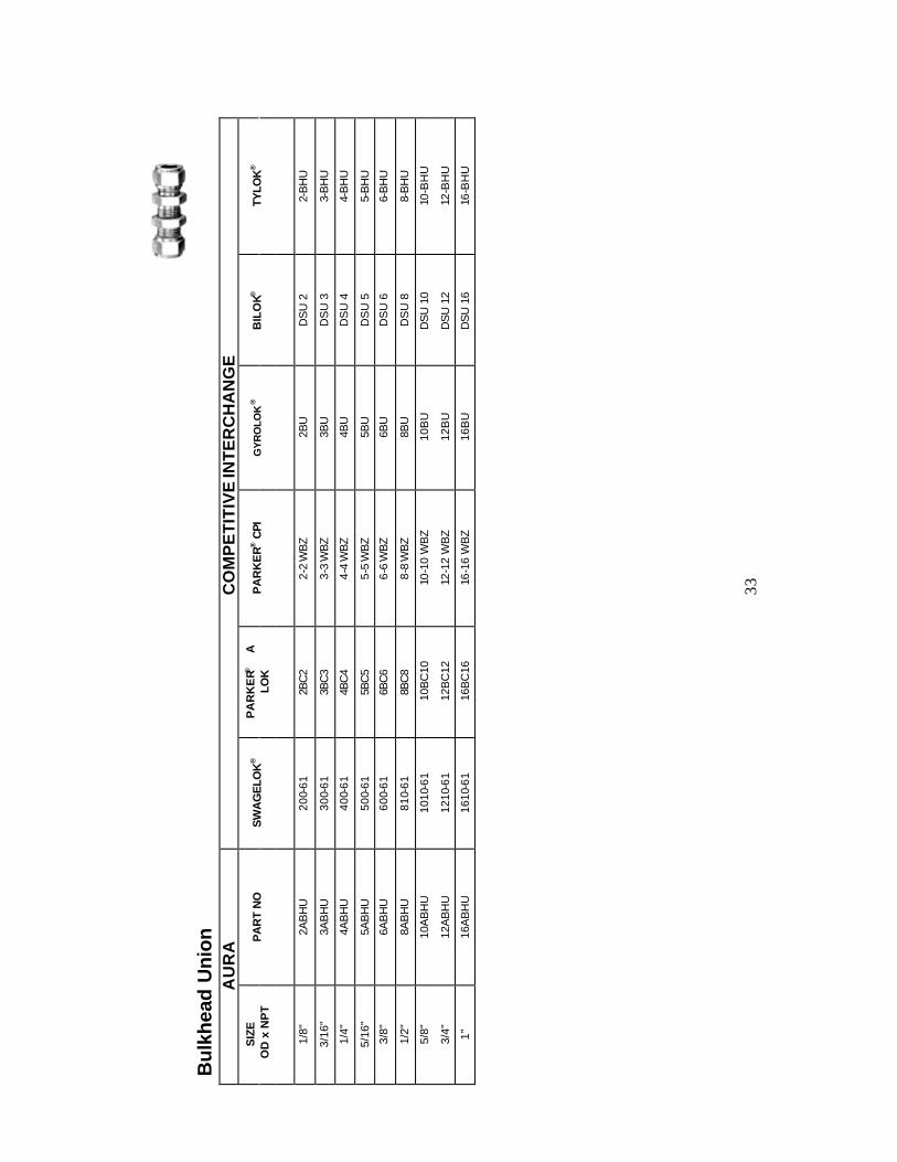
Bul
khea
d U
nion
AU
RA
CO
MP
ET
ITIV
E IN
TE
RC
HA
NG
E
SIZ
E O
D x
NP
T P
AR
T N
O
SW
AG
ELO
K®
PA
RK
ER®
A
LO
K
PA
RK
ER
® C
PI
GY
RO
LOK
®
BIL
OK®
TY
LOK
®
1/8"
2A
BH
U
200-
61
2BC
2
2-2
WB
Z
2BU
D
SU
2
2-B
HU
3/16
" 3A
BH
U
300-
61
3BC
3
3-3
WB
Z
3BU
D
SU
3
3-B
HU
1/4"
4A
BH
U
400-
61
4BC
4
4-4
WB
Z
4BU
D
SU
4
4-B
HU
5/16
" 5A
BH
U
500-
61
5BC
5
5-5
WB
Z
5BU
D
SU
5
5-B
HU
3/8"
6A
BH
U
600-
61
6BC
6
6-6
WB
Z
6BU
D
SU
6
6-B
HU
1/2"
8A
BH
U
810-
61
8BC
8
8-8
WB
Z
8BU
D
SU
8
8-B
HU
5/8"
10
AB
HU
10
10-6
1 10
BC
10
10-1
0 W
BZ
10B
U D
SU
10
10
-BH
U
3/4"
12
AB
HU
12
10-6
1 12
BC
12
12-1
2 W
BZ
12B
U D
SU
12
12
-BH
U
1”
16A
BH
U
1610
-61
16B
C16
16
-16
WB
Z 16
BU
DS
U 1
6
16-B
HU
33
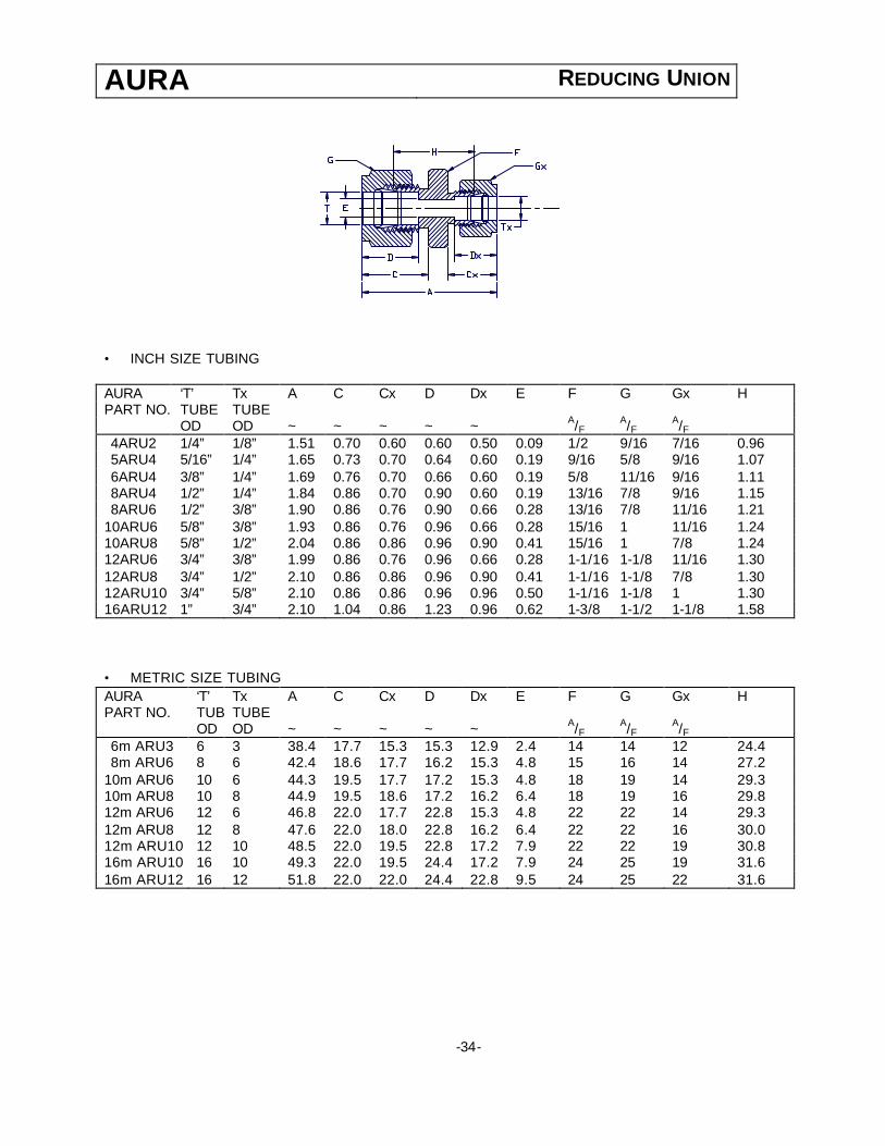
AURA REDUCING UNION
• INCH SIZE TUBING AURA ‘T’ Tx A C Cx D Dx E F G Gx H PART NO. TUBE TUBE OD OD ~ ~ ~ ~ ~ A/F A/F A/F 4ARU2 1/4” 1/8” 1.51 0.70 0.60 0.60 0.50 0.09 1/2 9/16 7/16 0.96 5ARU4 5/16” 1/4” 1.65 0.73 0.70 0.64 0.60 0.19 9/16 5/8 9/16 1.07 6ARU4 3/8” 1/4” 1.69 0.76 0.70 0.66 0.60 0.19 5/8 11/16 9/16 1.11 8ARU4 1/2” 1/4” 1.84 0.86 0.70 0.90 0.60 0.19 13/16 7/8 9/16 1.15 8ARU6 1/2” 3/8” 1.90 0.86 0.76 0.90 0.66 0.28 13/16 7/8 11/16 1.21
10ARU6 5/8” 3/8” 1.93 0.86 0.76 0.96 0.66 0.28 15/16 1 11/16 1.24 10ARU8 5/8” 1/2” 2.04 0.86 0.86 0.96 0.90 0.41 15/16 1 7/8 1.24 12ARU6 3/4” 3/8” 1.99 0.86 0.76 0.96 0.66 0.28 1-1/16 1-1/8 11/16 1.30 12ARU8 3/4” 1/2” 2.10 0.86 0.86 0.96 0.90 0.41 1-1/16 1-1/8 7/8 1.30 12ARU10 3/4” 5/8” 2.10 0.86 0.86 0.96 0.96 0.50 1-1/16 1-1/8 1 1.30 16ARU12 1” 3/4” 2.10 1.04 0.86 1.23 0.96 0.62 1-3/8 1-1/2 1-1/8 1.58 • METRIC SIZE TUBING AURA ‘T’ Tx A C Cx D Dx E F G Gx H PART NO. TUBETUBE OD OD ~ ~ ~ ~ ~ A/F A/F A/F 6m ARU3 6 3 38.4 17.7 15.3 15.3 12.9 2.4 14 14 12 24.4 8m ARU6 8 6 42.4 18.6 17.7 16.2 15.3 4.8 15 16 14 27.2
10m ARU6 10 6 44.3 19.5 17.7 17.2 15.3 4.8 18 19 14 29.3 10m ARU8 10 8 44.9 19.5 18.6 17.2 16.2 6.4 18 19 16 29.8 12m ARU6 12 6 46.8 22.0 17.7 22.8 15.3 4.8 22 22 14 29.3 12m ARU8 12 8 47.6 22.0 18.0 22.8 16.2 6.4 22 22 16 30.0 12m ARU10 12 10 48.5 22.0 19.5 22.8 17.2 7.9 22 22 19 30.8 16m ARU10 16 10 49.3 22.0 19.5 24.4 17.2 7.9 24 25 19 31.6 16m ARU12 16 12 51.8 22.0 22.0 24.4 22.8 9.5 24 25 22 31.6
-34-

Red
ucin
g U
nion
AU
RA
CO
MP
ET
ITIV
E IN
TE
RC
HA
NG
E
SIZ
E O
D x
NP
T P
AR
T N
O
SW
AG
ELO
K®
PA
RK
ER®
A
LO
K
PA
RK
ER
® C
PI
GY
RO
LOK
®
BIL
OK®
TY
LOK
®
3/16
" x
1/8"
3A
RU
2
300-
6-2
3-2
HB
Z 3R
U2
3UR
2 D
UR
3-2
3-
1RU
-2
1/4"
x 1
/8"
4AR
U2
40
0-6-
2 4-
2 H
BZ
4RU
2 4U
R2
DU
R 4
-2
4-1R
U-2
5/16
" x
1/4"
5A
RU
4
500-
6-4
5-4
HB
Z 5R
U4
5UR
4 D
UR
5-4
5-
1RU
-4
3/8"
x 1
/4"
6AR
U4
60
0-6-
4 6-
4 H
BZ
6RU
4 6U
R4
DU
R 6
-4
6-1R
U-4
1/2"
x 1
/4"
8AR
U4
81
0-6-
4 8-
4 H
BZ
8RU
4 8U
R4
DU
R 8
-4
8-1R
U-4
1/2"
x 3
/8"
8AR
U6
81
0-6-
6 8-
6 H
BZ
8RU
6 8U
R6
DU
R 8
-6
8-1R
U-6
5/8"
x 3
/8"
10AR
U6
10
10-6
-6
10-6
HB
Z 10
RU
6 10
UR
6 D
UR
10-
6 10
-1R
U-6
5/8"
x 1
/2"
10AR
U8
10
10-6
-8
10-8
HB
Z 10
RU
8 10
UR
8 D
UR
10-
8 10
-1R
U-8
3/4"
x 1
/2"
12AR
U8
12
10-6
-8
12-8
HB
Z 12
RU
8 12
UR
8 D
UR
12-
8 12
-1R
U-8
3/4"
x 5
/8"
12A
RU
10
1210
-6-1
0 12
-10
HB
Z
12R
U10
12
UR
10
DU
R 1
2-10
12
-1R
U-1
0
1" x
3/4
" 16
AR
U12
16
10-6
-12
16-1
2 H
BZ
16
RU
12
16U
R12
D
UR
16-
12
16-1
RU
-12
35
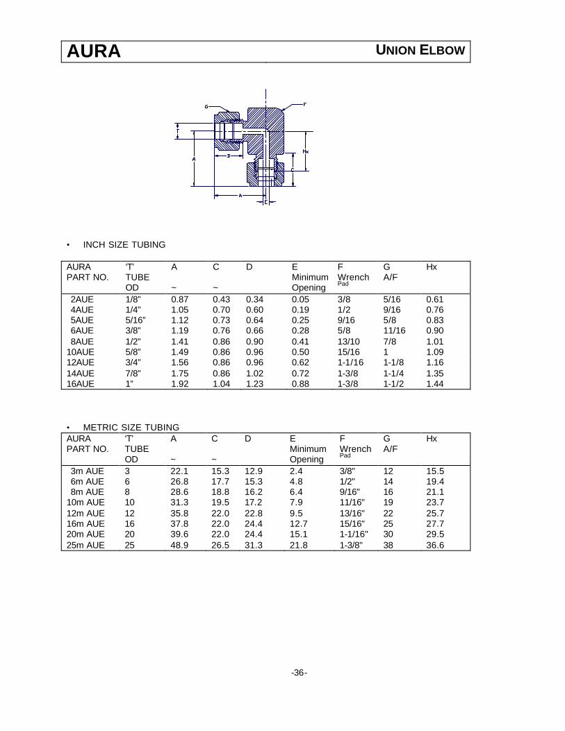
AURA UNION ELBOW
• INCH SIZE TUBING AURA ‘T’ A C D E F G Hx PART NO. TUBE Minimum Wrench A/F OD ~ ~ Opening Pad
2AUE 1/8” 0.87 0.43 0.34 0.05 3/8 5/16 0.61 4AUE 1/4” 1.05 0.70 0.60 0.19 1/2 9/16 0.76 5AUE 5/16” 1.12 0.73 0.64 0.25 9/16 5/8 0.83 6AUE 3/8” 1.19 0.76 0.66 0.28 5/8 11/16 0.90 8AUE 1/2” 1.41 0.86 0.90 0.41 13/10 7/8 1.01
10AUE 5/8” 1.49 0.86 0.96 0.50 15/16 1 1.09 12AUE 3/4” 1.56 0.86 0.96 0.62 1-1/16 1-1/8 1.16 14AUE 7/8” 1.75 0.86 1.02 0.72 1-3/8 1-1/4 1.35 16AUE 1” 1.92 1.04 1.23 0.88 1-3/8 1-1/2 1.44 • METRIC SIZE TUBING AURA ‘T’ A C D E F G Hx PART NO. TUBE Minimum Wrench A/F OD ~ ~ Opening Pad
3m AUE 3 22.1 15.3 12.9 2.4 3/8" 12 15.5 6m AUE 6 26.8 17.7 15.3 4.8 1/2" 14 19.4 8m AUE 8 28.6 18.8 16.2 6.4 9/16" 16 21.1
10m AUE 10 31.3 19.5 17.2 7.9 11/16" 19 23.7 12m AUE 12 35.8 22.0 22.8 9.5 13/16" 22 25.7 16m AUE 16 37.8 22.0 24.4 12.7 15/16" 25 27.7 20m AUE 20 39.6 22.0 24.4 15.1 1-1/16" 30 29.5 25m AUE 25 48.9 26.5 31.3 21.8 1-3/8" 38 36.6
-36-

Uni
on E
lbow
AU
RA
CO
MP
ET
ITIV
E IN
TE
RC
HA
NG
E
SIZ
E O
D x
NP
T P
AR
T N
O
SW
AG
ELO
K®
PA
RK
ER®
A
LO
K
PA
RK
ER
® C
PI
GY
RO
LOK
®
BIL
OK®
TY
LOK
®
1/8"
2A
UE
20
0-9
2EE
2
2-2
EBZ
2L
U
DLA
2
2-2
ELU
-2
3/16
" 3A
UE
30
0-9
3EE
3
3-3
EBZ
3L
U
DLA
3
3-2
ELU
-3
1/4"
4A
UE
40
0-9
4EE
4
4-4
EBZ
4L
U
DLA
4
4-2
ELU
-4
5/16
" 5A
UE
50
0-9
5EE
5
5-5
EBZ
5L
U
DLA
5 5-
2 E
LU-5
3/8"
6A
UE
60
0-9
6EE
6
6-6
EBZ
6L
U
DLA
6 6-
2 E
LU-6
1/2"
8A
UE
81
0-9
8EE
8
8-8
EBZ
8L
U
DLA
8 8-
2 E
LU-8
5/8"
10
AUE
10
10-9
10
EE
10
10-1
0 E
BZ
10LU
D
LA10
10
-2 E
LU-1
0
3/4"
12
AUE
12
10-9
12
EE
12
12-1
2 E
BZ
12LU
D
LA12
12
-2 E
LU-1
2
1”
16AU
E
1610
-9
16E
E16
16
-16
EB
Z 16
LU
DLA
16
16-2
ELU
-16
37

AURA UNION TEE
• INCH SIZE TUBING AURA ‘T’ A Ax C D E F G H Hx PART NO. TUBE Minimum Wrench Hex A/F OD ~ ~ Opening Pad
2AUT 1/8” 1.76 0.60 0.50 0.09 3/8 7/16 0.87 1.22 4AUT 1/4” 2.12 0.70 0.60 0.19 1/2 9/16 1.05 1.52 5AUT 5/16” 2.34 0.73 0.64 0.25 5/8 5/8 1.16 1.74 6AUT 3/8” 2.40 0.76 0.66 0.28 5/8 11/16 1.19 1.80 8AUT 1/2” 2.84 0.86 0.96 0.41 13/16 7/8 1.41 2.02
10AUT 5/8” 3.06 0.86 0.96 0.50 1 1 1.52 2.24 12AUT 3/4” 3.14 0.86 0.96 0.62 1-1/16 1-1/8 1.56 2.32 14AUT 7/8” 3.52 0.86 1.02 0.72 1-3/8 1-1/4 1.75 2.70 16AUT 1” 3.86 1.04 1.23 0.88 1-3/8 1-1/2 1.92 2.88 • METRIC SIZE TUBING AURA ‘T’ A Ax C D E F G H Hx PART NO. TUBE Minimum Wrench Hex A/F OD ~ ~ Opening Pad
3m AUT 3 44.2 22.1 15.3 12.9 2.4 3/8” 12 31.0 15.5 6m AUT 6 53.6 26.8 17.7 15.3 4.8 1/2” 14 38.8 19.4 8m AUT 8 59.4 29.7 18.6 16.2 6.4 5/8” 16 44.4 22.2
10m AUT 10 62.6 31.3 19.5 17.2 7.9 11/16” 19 47.4 23.7 12m AUT 12 71.6 35.8 22.0 22.8 9.5 13/16 22 51.4 25.7 16m AUT 16 77.2 38.6 22.0 24.4 12.7 1” 25 57.0 28.7 20m AUT 20 88.8 44.4 22.0 26.0 15.9 1-3/8” 32 68.6 34.3 25m AUT 25 97.8 48.9 26.5 31.3 21.8 1-3/8” 38 73.2 36.6
-38-
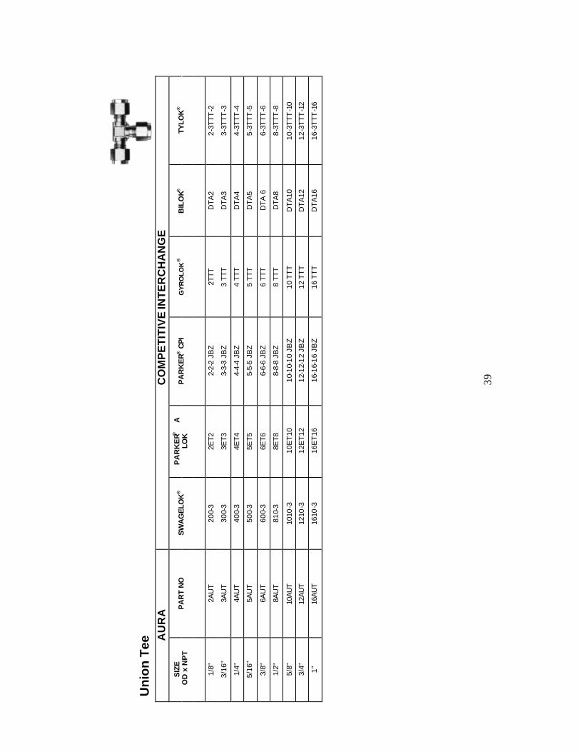
Un
ion
Tee
AU
RA
CO
MP
ET
ITIV
E IN
TE
RC
HA
NG
E
SIZ
E O
D x
NP
T P
AR
T N
O
SW
AG
ELO
K®
PA
RK
ER®
A
LO
K
PA
RK
ER
® C
PI
GY
RO
LOK
®
BIL
OK®
TY
LOK
®
1/8"
2A
UT
200-
3 2E
T2
2-2-
2 JB
Z
2TTT
D
TA2
2-3T
TT-2
3/16
" 3A
UT
300-
3 3E
T3
3-3-
3 JB
Z
3 TT
T D
TA3
3-3T
TT-3
1/4"
4A
UT
400-
3 4E
T4
4-4-
4 JB
Z
4 TT
T D
TA4
4-3T
TT-4
5/16
" 5A
UT
500-
3 5E
T5
5-5-
5 JB
Z 5
TTT
DTA
5 5-
3TTT
-5
3/8"
6A
UT
600-
3 6E
T6
6-6-
6 JB
Z
6 TT
T D
TA 6
6-
3TTT
-6
1/2"
8A
UT
810-
3 8E
T8
8-8-
8 JB
Z
8 TT
T D
TA8
8-3T
TT-8
5/8"
10
AU
T
1010
-3
10E
T10
10
-10-
10 J
BZ
10 T
TT
D
TA
10
10-3
TTT
-10
3/4"
12
AU
T
1210
-3
12E
T12
12
-12-
12 J
BZ
12 T
TT
D
TA
12
12-3
TTT
-12
1”
16A
UT
16
10-3
16
ET
16
16-1
6-16
JB
Z 16
TT
T
DT
A16
16
-3TT
T-1
6
39
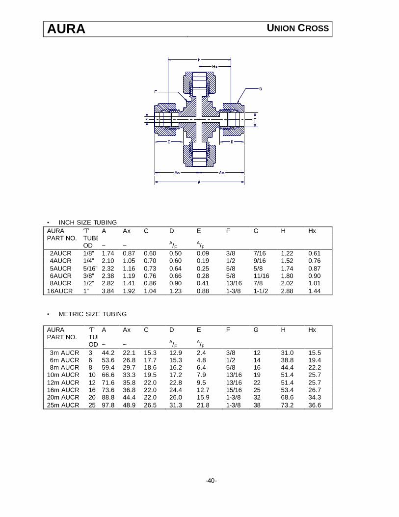
AURA UNION CROSS
• INCH SIZE TUBING AURA ‘T’ A Ax C D E F G H Hx PART NO. TUBE OD ~ ~ A/F A/F
2AUCR 1/8” 1.74 0.87 0.60 0.50 0.09 3/8 7/16 1.22 0.61 4AUCR 1/4” 2.10 1.05 0.70 0.60 0.19 1/2 9/16 1.52 0.76 5AUCR 5/16” 2.32 1.16 0.73 0.64 0.25 5/8 5/8 1.74 0.87 6AUCR 3/8” 2.38 1.19 0.76 0.66 0.28 5/8 11/16 1.80 0.90 8AUCR 1/2” 2.82 1.41 0.86 0.90 0.41 13/16 7/8 2.02 1.01
16AUCR 1” 3.84 1.92 1.04 1.23 0.88 1-3/8 1-1/2 2.88 1.44 • METRIC SIZE TUBING AURA ‘T’ A Ax C D E F G H Hx PART NO. TUBE OD ~ ~ A/F A/F
3m AUCR 3 44.2 22.1 15.3 12.9 2.4 3/8 12 31.0 15.5 6m AUCR 6 53.6 26.8 17.7 15.3 4.8 1/2 14 38.8 19.4 8m AUCR 8 59.4 29.7 18.6 16.2 6.4 5/8 16 44.4 22.2
10m AUCR 10 66.6 33.3 19.5 17.2 7.9 13/16 19 51.4 25.7 12m AUCR 12 71.6 35.8 22.0 22.8 9.5 13/16 22 51.4 25.7 16m AUCR 16 73.6 36.8 22.0 24.4 12.7 15/16 25 53.4 26.7 20m AUCR 20 88.8 44.4 22.0 26.0 15.9 1-3/8 32 68.6 34.3 25m AUCR 25 97.8 48.9 26.5 31.3 21.8 1-3/8 38 73.2 36.6
-40-

Uni
on C
ross
A
UR
A
C
OM
PE
TIT
IVE
INT
ER
CH
AN
GE
S
IZE
OD
x N
PT
PA
RT
NO
S
WA
GE
LOK
®
PA
RK
ER®
A
LO
K
PA
RK
ER
® C
PI
GY
RO
LOK
®
BIL
OK®
TY
LOK
®
1/8”
2A
UC
R
200-
4 2E
CR
2 2K
BZ
2C
DX
A2
2-4C
R
1/4”
4A
UC
R
400-
4 4E
CR
4 4K
BZ
4C
DX
A4
4-4C
R
5/16
” 5A
UC
R
500-
4 5E
CR
5 5K
BZ
5C
DX
A5
5-4C
R
3/8”
6A
UC
R
600-
4 6E
CR
6 6K
BZ
6C
DX
A6
6-4C
R
1/2”
8A
UC
R
810-
4 8E
CR
8 8K
BZ
8C
DX
A8
8-4C
R
5/8”
10
AU
CR
10
10-4
10
EC
R10
10
KB
Z 10
C
DX
A10
10
-4C
R
3/4”
12
AU
CR
12
10-4
12
EC
R12
12
KB
Z 12
C
DX
A12
12
-4C
R
1”
16A
UC
R
1610
-4
16E
CR
16
16K
BZ
16C
D
XA
16
16-4
CR
41
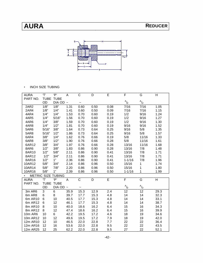
AURA REDUCER
• INCH SIZE TUBING AURA ‘T’ ‘P’ A C D E F G H PART NO. TUBE TUBE OD DIA OD ~ ~ A/F
A/F
2AR2 1/8” 1/8” 1.31 0.60 0.50 0.08 7/16 7/16 1.05 2AR4 1/8” 1/4” 1.41 0.60 0.50 0.09 7/16 7/16 1.15 4AR4 1/4” 1/4” 1.53 0.70 0.60 0.19 1/2 9/16 1.24 4AR5 1/4” 5/16” 1.56 0.70 0.60 0.19 1/2 9/16 1.27 4AR6 1/4” 3/8” 1.59 0.70 0.60 0.19 1/2 9/16 1.30 4AR8 1/4” 1/2” 1.81 0.70 0.60 0.19 9/16 9/16 1.52 5AR6 5/16” 3/8” 1.64 0.73 0.64 0.25 9/16 5/8 1.35 5AR8 5/16” 1/2” 1.86 0.73 0.64 0.25 9/16 5/8 1.57 6AR4 3/8” 1/4” 1.62 0.76 0.66 0.19 5/8 11/16 1.33 6AR8 3/8” 1/2” 1.90 0.76 0.66 0.28 5/8 11/16 1.61 6AR12 3/8” 3/4” 1.97 0.76 0.66 0.28 13/16 11/16 1.68 8AR6 1/2” 3/8” 1.83 0.86 0.90 0.28 13/16 7/8 1.48 8AR10 1/2” 5/8” 2.11 0.86 0.90 0.41 13/16 7/8 1.71 8AR12 1/2” 3/4” 2.11 0.86 0.90 0.41 13/16 7/8 1.71 8AR16 1/2” 1” 2.36 0.86 0.90 0.41 1-1/16 7/8 1.96
10AR12 5/8” 3/4” 2.14 0.86 0.96 0.50 15/16 1 1.74 10AR14 5/8” 7/8” 2.20 0.86 0.96 0.50 15/16 1 1.80 10AR16 5/8” 1” 2.39 0.86 0.96 0.50 1-1/16 1 1.99 • METRIC SIZE TUBING AURA ‘T’ ‘P’ A C D E F G H PART NO. TUBE TUBE OD DIA OD ~ ~ A/F
A/F
3m AR6 3 6 35.9 15.3 12.9 2.4 12 12 29.3 6m AR8 6 8 39.7 17.7 15.3 4.8 14 14 32.3 6m AR10 6 10 40.5 17.7 15.3 4.8 14 14 33.1 6m AR12 6 12 46.1 17.7 15.3 4.8 14 14 38.7 8m AR10 8 10 40.0 18.6 16.2 6.4 15 16 34.3 8m AR12 8 12 47.4 18.6 16.2 6.4 15 16 39.9
10m AR6 10 6 42.2 19.5 17.2 4.6 18 19 34.6 10m AR12 10 12 49.6 19.5 17.2 7.9 18 19 42.0 12m AR10 12 10 46.5 22.0 22.8 7.7 22 22 36.4 12m AR16 12 16 53.6 22.0 22.8 9.5 22 22 43.5 12m AR25 12 25 62.2 22.0 22.8 9.5 27 22 52.1
-42-
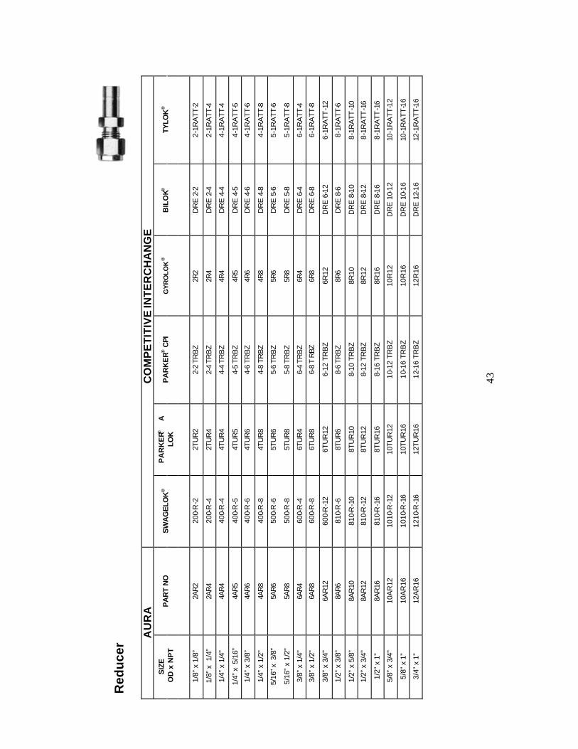
Red
uce
r
AU
RA
CO
MP
ET
ITIV
E IN
TE
RC
HA
NG
E
SIZ
E O
D x
NP
T P
AR
T N
O
SW
AG
ELO
K®
PA
RK
ER®
A
LO
K
PA
RK
ER
® C
PI
GY
RO
LOK
®
BIL
OK®
TY
LOK
®
1/8”
x 1
/8”
2AR
2
200-
R-2
2T
UR
2 2-
2 TR
BZ
2R
2
DR
E 2
-2
2-1R
ATT
-2
1/8”
x 1
/4”
2AR
4
200-
R-4
2T
UR
4 2-
4 TR
BZ
2R
4
DR
E 2
-4
2-1R
ATT
-4
1/4”
x 1
/4"
4AR
4
400-
R-4
4T
UR
4 4-
4 TR
BZ
4R
4
DR
E 4
-4
4-1R
ATT
-4
1/4”
x 5
/16”
4A
R5
40
0-R
-5
4TU
R5
4-5
TRB
Z
4R5
D
RE
4-5
4-
1RA
TT-5
1/4”
x 3
/8”
4AR
6
400-
R-6
4T
UR
6 4-
6 TR
BZ
4R
6
DR
E 4
-6
4-1R
ATT
-6
1/4”
x 1
/2"
4AR
8
400-
R-8
4T
UR
8 4-
8 TR
BZ
4R
8
DR
E 4
-8
4-1R
ATT
-8
5/16
” x 3
/8”
5AR
6
500-
R-6
5T
UR
6 5-
6 TR
BZ
5R
6
DR
E 5
-6
5-1R
ATT
-6
5/16
” x
1/2"
5A
R8
50
0-R
-8
5TU
R8
5-8
TRB
Z
5R8
D
RE
5-8
5-
1RA
TT-8
3/8”
x 1
/4"
6AR
4
600-
R-4
6T
UR
4 6-
4 TR
BZ
6R
4
DR
E 6
-4
6-1R
ATT
-4
3/8”
x 1
/2"
6AR
8
600-
R-8
6T
UR
8 6-
8 T
RBZ
6R
8
DR
E 6
-8
6-1R
ATT
-8
3/8”
x 3
/4"
6AR
12
600-
R-1
2 6T
UR
12
6-12
TR
BZ
6R12
D
RE
6-1
2 6-
1RA
TT-1
2
1/2”
x 3
/8”
8AR
6
810-
R-6
8T
UR
6 8-
6 TR
BZ
8R
6
DR
E 8
-6
8-1R
ATT
-6
1/2”
x 5
/8”
8AR
10
810-
R-1
0 8T
UR
10
8-10
TR
BZ
8R10
D
RE
8-1
0 8-
1RA
TT-1
0
1/2”
x 3
/4"
8AR
12
810-
R-1
2 8T
UR
12
8-12
TR
BZ
8R12
D
RE
8-1
2 8-
1RA
TT-1
6
1/2”
x 1
” 8A
R16
81
0-R
-16
8TU
R16
8-
16 T
RB
Z 8R
16
DR
E 8
-16
8-1R
ATT
-16
5/8”
x 3
/4"
10A
R12
10
10-R
-12
10TU
R12
10
-12
TRB
Z 10
R12
D
RE
10-
12
10-1
RA
TT-1
2
5/8”
x 1
” 10
AR
16
1010
-R-1
6 10
TUR
16
10-1
6 TR
BZ
10R
16
DR
E 1
0-16
10
-1R
AT
T-1
6
3/4”
x 1
” 12
AR
16
1210
-R-1
6 12
TUR
16
12-1
6 TR
BZ
12R
16
DR
E 1
2-16
12
-1R
ATT
-16
43
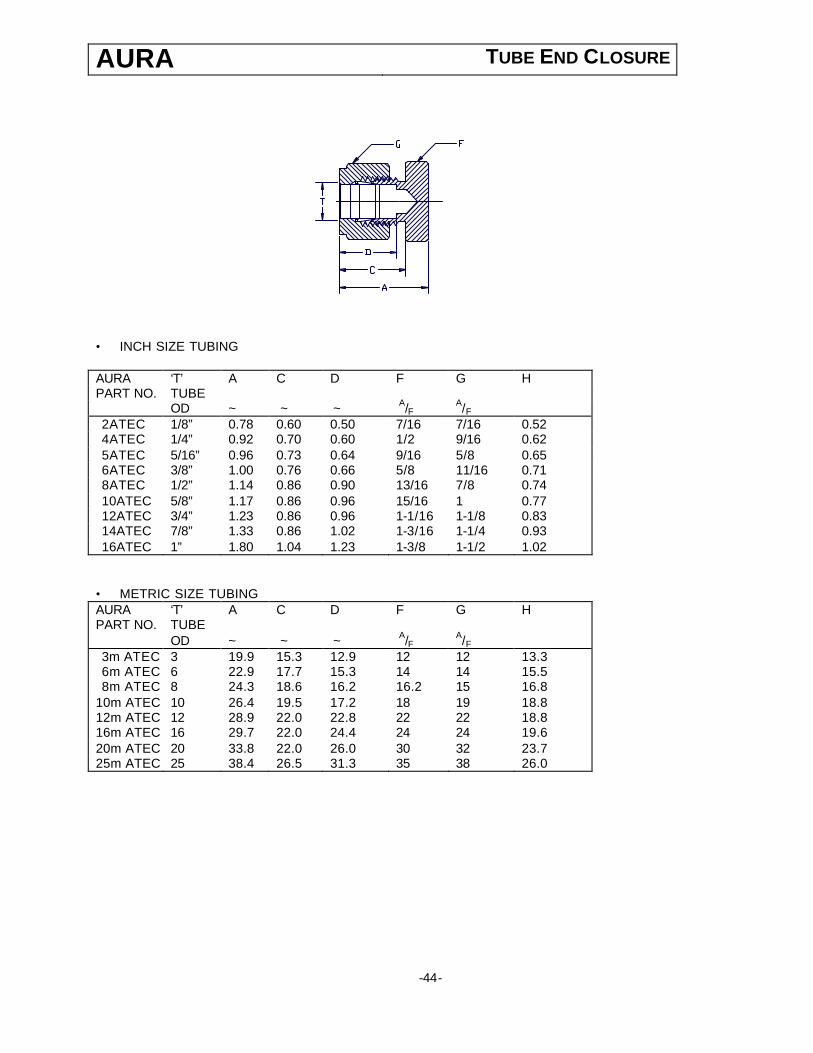
AURA TUBE END CLOSURE
• INCH SIZE TUBING AURA ‘T’ A C D F G H PART NO. TUBE OD ~ ~ ~ A/F
A/F
2ATEC 1/8” 0.78 0.60 0.50 7/16 7/16 0.52 4ATEC 1/4” 0.92 0.70 0.60 1/2 9/16 0.62 5ATEC 5/16” 0.96 0.73 0.64 9/16 5/8 0.65 6ATEC 3/8” 1.00 0.76 0.66 5/8 11/16 0.71 8ATEC 1/2” 1.14 0.86 0.90 13/16 7/8 0.74 10ATEC 5/8” 1.17 0.86 0.96 15/16 1 0.77 12ATEC 3/4” 1.23 0.86 0.96 1-1/16 1-1/8 0.83 14ATEC 7/8” 1.33 0.86 1.02 1-3/16 1-1/4 0.93 16ATEC 1” 1.80 1.04 1.23 1-3/8 1-1/2 1.02
• METRIC SIZE TUBING AURA ‘T’ A C D F G H PART NO. TUBE OD ~ ~ ~ A/F
A/F
3m ATEC 3 19.9 15.3 12.9 12 12 13.3 6m ATEC 6 22.9 17.7 15.3 14 14 15.5 8m ATEC 8 24.3 18.6 16.2 16.2 15 16.8
10m ATEC 10 26.4 19.5 17.2 18 19 18.8 12m ATEC 12 28.9 22.0 22.8 22 22 18.8 16m ATEC 16 29.7 22.0 24.4 24 24 19.6 20m ATEC 20 33.8 22.0 26.0 30 32 23.7 25m ATEC 25 38.4 26.5 31.3 35 38 26.0
-44-
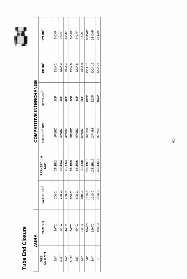
Tu
be
En
d C
losu
re
AU
RA
CO
MP
ET
ITIV
E IN
TE
RC
HA
NG
E
SIZ
E
OD
x N
PT
PA
RT
NO
S
WA
GE
LO
K®
PA
RK
ER
®
A
LOK
P
AR
KE
R® C
PI
GY
RO
LO
K®
BIL
OK
®
TYLO
K®
1/8"
2A
TC
200-
C
2BLE
N2
2PN
BZ
2CP
D
CA
2
2-C
AP
3/16
" 3A
TC
300-
C
3BLE
N3
3PN
BZ
3CP
D
CA
3
3-C
AP
1/4"
4A
TC
400-
C
4BLE
N4
4PN
BZ
4CP
D
CA
4
4-C
AP
5/16
" 5A
TC
500-
C
5BLE
N5
5PN
BZ
5CP
D
CA
5
5-C
AP
3/8"
6A
TC
600-
C
6BLE
N6
6PN
BZ
6CP
D
CA
6
6-C
AP
1/2"
8A
TC
810-
C
8BLE
N8
8PN
BZ
8CP
D
CA
8
8-C
AP
5/8"
10
ATC
10
10-C
10
BLE
N10
10
PN
BZ
10C
P
DC
A 1
0 10
-CA
P
3/4"
12
ATC
12
10-C
12
BLE
N12
12
PN
BZ
12C
P
DC
A 1
2 12
-CA
P
1”
16A
TC
1610
-C
16B
LEN
16
16P
NB
Z 16
CP
D
CA
16
16-C
AP
45
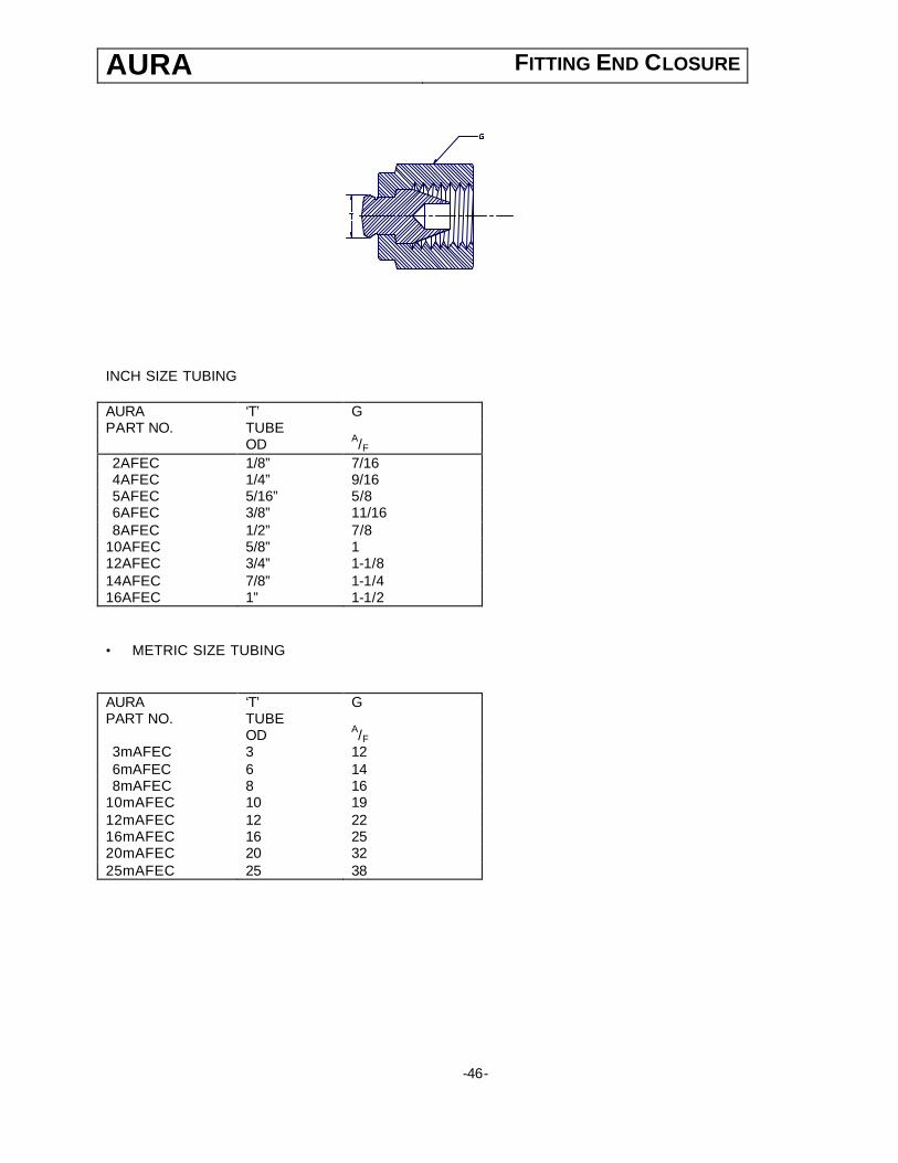
AURA FITTING END CLOSURE
INCH SIZE TUBING AURA ‘T’ G PART NO. TUBE OD A/F
2AFEC 1/8” 7/16 4AFEC 1/4” 9/16 5AFEC 5/16” 5/8 6AFEC 3/8” 11/16 8AFEC 1/2” 7/8
10AFEC 5/8” 1 12AFEC 3/4” 1-1/8 14AFEC 7/8” 1-1/4 16AFEC 1” 1-1/2 • METRIC SIZE TUBING AURA ‘T’ G PART NO. TUBE OD A/F
3mAFEC 3 12 6mAFEC 6 14 8mAFEC 8 16
10mAFEC 10 19 12mAFEC 12 22 16mAFEC 16 25 20mAFEC 20 32 25mAFEC 25 38
-46-
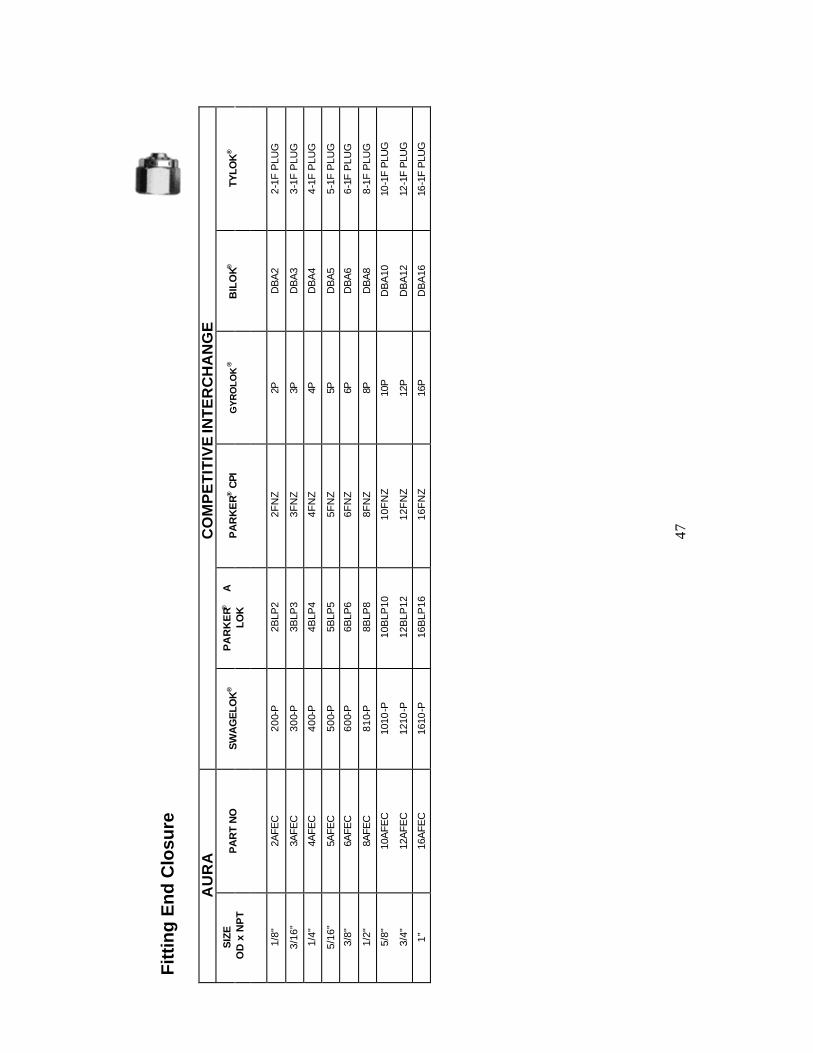
Fitt
ing
En
d C
losu
re
AU
RA
CO
MP
ET
ITIV
E IN
TE
RC
HA
NG
E
SIZ
E O
D x
NP
T P
AR
T N
O
SW
AG
ELO
K®
PA
RK
ER®
A
LO
K
PA
RK
ER
® C
PI
GY
RO
LOK
®
BIL
OK®
TY
LOK
®
1/8"
2A
FEC
20
0-P
2B
LP2
2FN
Z 2P
D
BA
2 2-
1F P
LUG
3/16
" 3A
FEC
30
0-P
3B
LP3
3FN
Z 3P
D
BA
3 3-
1F P
LUG
1/4"
4A
FEC
40
0-P
4B
LP4
4FN
Z 4P
D
BA
4 4-
1F P
LUG
5/16
" 5A
FEC
50
0-P
5B
LP5
5FN
Z 5P
D
BA
5 5-
1F P
LUG
3/8"
6A
FEC
60
0-P
6B
LP6
6FN
Z 6P
D
BA
6 6-
1F P
LUG
1/2"
8A
FEC
81
0-P
8B
LP8
8FN
Z 8P
D
BA
8 8-
1F P
LUG
5/8"
10
AFE
C
1010
-P
10B
LP10
10
FN
Z 10
P
DB
A10
10
-1F
PLU
G
3/4"
12
AFE
C
1210
-P
12B
LP12
12
FN
Z 12
P
DB
A12
12
-1F
PLU
G
1”
16A
FEC
16
10-P
16
BLP
16
16F
NZ
16P
D
BA
16
16-1
F P
LUG
47

AURA FRONT FERRULE
INCH SIZE TUBING METRIC SIZE TUBING AURA PART NO. ‘T’ TUBE OD AURA PART NO. ‘T’ TUBE OD 2AFF 1/8” 3m AFF 3 4AFF 1/4” 6m AFF 6 5AFF 5/16” 8m AFF 8 6AFF 3/8” 10m AFF 10 8AFF 1/2” 12m AFF 12
10AFF 5/8” 16m AFF 16 12AFF 3/4” 20m AFF 20 14AFF 7/8” 25m AFF 25 16AFF 1”
-48-
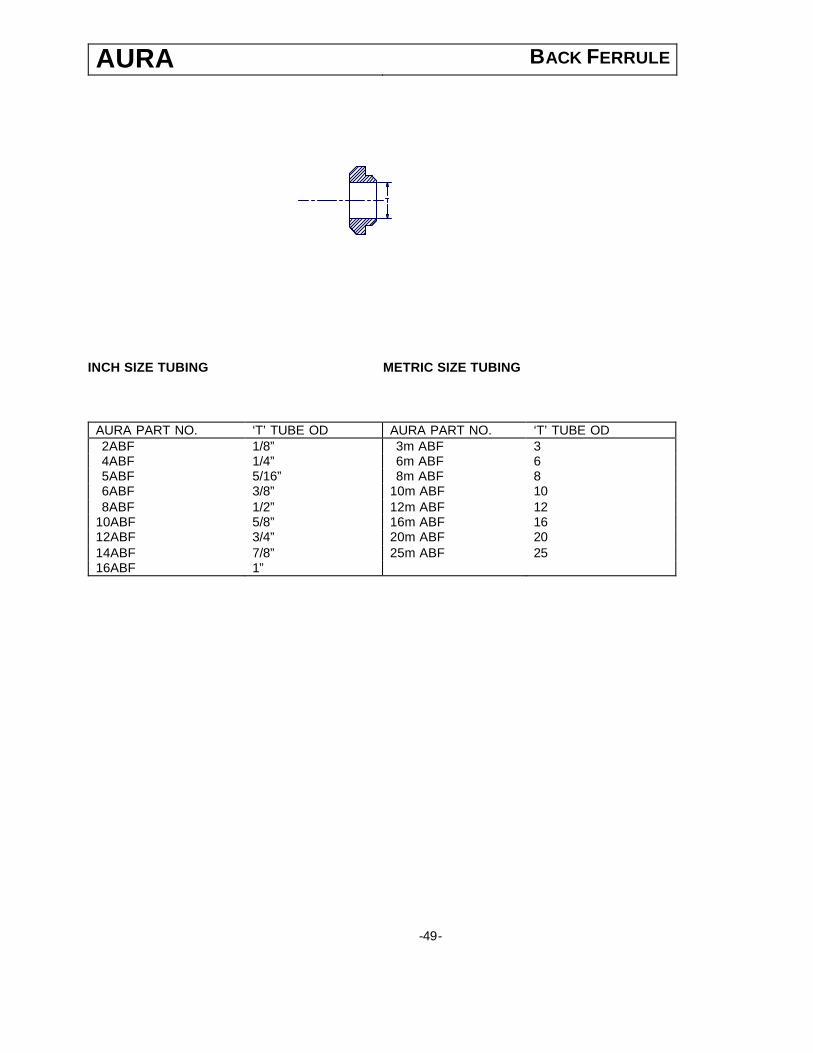
AURA BACK FERRULE
INCH SIZE TUBING METRIC SIZE TUBING AURA PART NO. ‘T’ TUBE OD AURA PART NO. ‘T’ TUBE OD 2ABF 1/8” 3m ABF 3 4ABF 1/4” 6m ABF 6 5ABF 5/16” 8m ABF 8 6ABF 3/8” 10m ABF 10 8ABF 1/2” 12m ABF 12
10ABF 5/8” 16m ABF 16 12ABF 3/4” 20m ABF 20 14ABF 7/8” 25m ABF 25 16ABF 1”
-49-
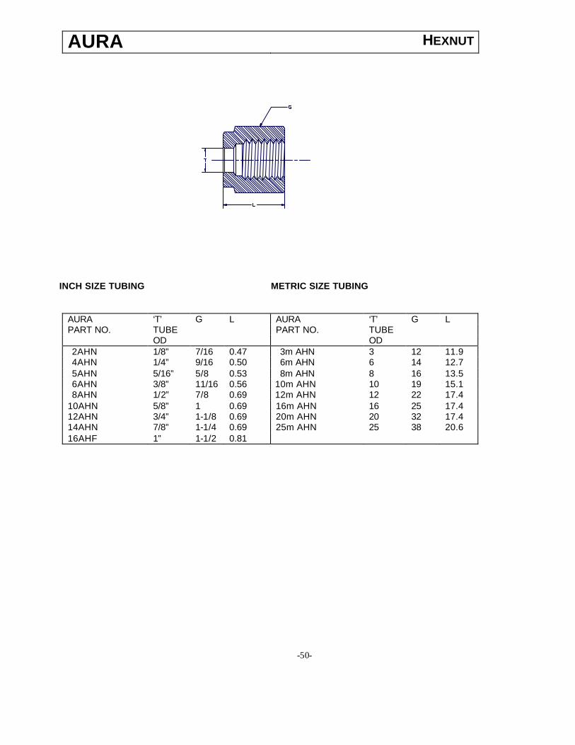
AURA HEXNUT
INCH SIZE TUBING METRIC SIZE TUBING
AURA ‘T’ G L AURA ‘T’ G L PART NO. TUBE PART NO. TUBE OD OD 2AHN 1/8” 7/16 0.47 3m AHN 3 12 11.9 4AHN 1/4” 9/16 0.50 6m AHN 6 14 12.7 5AHN 5/16” 5/8 0.53 8m AHN 8 16 13.5 6AHN 3/8” 11/16 0.56 10m AHN 10 19 15.1 8AHN 1/2” 7/8 0.69 12m AHN 12 22 17.4
10AHN 5/8” 1 0.69 16m AHN 16 25 17.4 12AHN 3/4” 1-1/8 0.69 20m AHN 20 32 17.4 14AHN 7/8” 1-1/4 0.69 25m AHN 25 38 20.6 16AHF 1” 1-1/2 0.81
-50-

AURA TOTAL QUALITY PROGRAM The Total Quality Management System employed by Aura Inc. covers all aspects of Engineering, Documentation, Production Planning, Incoming Inspection, Stage Inspection, Final Product Inspection, Packing & Dispatch. The system ensures appropriate action in our Customer Service, Engineering and Manufacturing divisions, to produce and maintain adequate documentation and inspection systems capable of producing evidence that material or services conform to the specified requirements, through all stages of the company’s operations. Total Quality Management at Aura Inc. is an on-going process that is constantly upgraded and monitored to keep pace with the company’s growth rate and diversification plans. The Quality Program includes, but is not limited to, the following areas: § Standard Operating Procedures and standard formats to ensure high degree of
accuracy in interpreting and responding to client requirements for technical information and quotations.
§ Order entry and production planning systems ensure that client orders are entered and
processed with a clear understanding of client requirements so that the final product conforms to the Purchase Order requirements by way of product specifications and delivery.
§ Documentation control and conformance to international standards & practices ensures
a high degree of accuracy and quality of Engineering. § Supervision of quality procedures at sub vendor’s works to ensure that incoming
materials are processed and manufactured to Aura’s purchase specifications, thus ensuring that final production plans are on schedule.
§ Quality plans for individual products covering all aspects of incoming, stage & final
inspection including parameters to be checked, reference documents, methods of chec king, instruments used, frequency of checking, format of recording and person responsible.
§ Standard & procedures for packing and standard dispatch documentation ensure that
products are adequately packed for the mode of shipment and documentation is accurate and meet requirements of client purchase orders, airlines/ shipping line & customs at the ports of dispatch and entry.
51

AU
RA
T
YP
ICA
L Q
UA
LITY
PLA
N
CO
MP
ON
EN
T C
ATE
GO
RY
OR
O
PE
RA
TIO
N
PA
RA
ME
TER
R
EFE
RE
NC
E
DO
CU
ME
NT
ME
THO
D
OF
CH
EC
KIN
G
INS
TRU
ME
NTS
U
SE
D
FRE
QU
EN
CY
O
F C
HE
CK
ING
FO
RM
AT
OF
RE
CO
RD
ING
R
ES
PO
NS
IBIL
ITY
Mat
eria
l C
ompo
sitio
n
Rel
evan
t S
td
/ D
raw
ing
Che
mic
al
Ana
lysi
s
( O
ptio
nal –
spo
t te
st)
Inde
pend
ent L
ab/
9V c
ell a
nd
Ele
ctro
lyte
so
lutio
n fo
r de
tect
ion
of M
b so
lutio
n
Sam
ple
M
TR
/ R
aw
Mat
eria
l rep
ort
AI/Q
C/0
1
QC
Insp
ecto
r
F
orm
fini
sh
Vis
ual
100%
Insp
ectio
n R
epor
t A
I/QC
/03
QC
Insp
ecto
r
E
xter
nal
& In
tern
al
Thr
eadi
ng
M
easu
rem
ent
S
tand
ard
Thr
ead
Rin
g / P
lug
gaug
e
Sam
ple
to 1
00%
- do
- Q
C In
spec
tor
T
hrea
d Le
ngth
- E
xter
nal &
In
tern
al
M
easu
rem
ent
Ver
nier
Cal
iper
s S
ampl
e -
do -
QC
Insp
ecto
r
T
ube
OD
S
tand
ard
Pin
10
0%
- do
- Q
C In
spec
tor
T
ube
OD
Le
ngth
Mea
sure
men
t V
erni
er C
alip
ers
Sam
ple
- do
- Q
C In
spec
tor
M
in. O
peni
ng
M
easu
rem
ent
Ver
nier
Cal
iper
s S
ampl
e -
do -
QC
Insp
ecto
r
Hex
A/f
- Bod
y
Mea
sure
men
t V
erni
er C
alip
ers
Sam
ple
- do
- Q
C In
spec
tor
H
ex A
/f - N
ut
M
easu
rem
ent
Ver
nier
Cal
iper
s S
ampl
e -
do -
QC
Insp
ecto
r
Com
pres
sion
Tu
be F
ittin
g
( Mal
e C
onne
ctor
) ( M
ale
Elb
ow )
( M
ale
Run
Tee
) (M
ale
Bra
nch
Tee
) (M
ale
Ada
pter
) (F
emal
e C
onne
ctor
) (F
emal
e E
lbow
) (F
emal
e R
un T
ee)
(Fem
ale
Bra
nch
Tee
) (F
emal
e A
dapt
er)
(Str
aigh
t Uni
on)
(Bul
khea
d U
nion
) (R
educ
ing
Uni
on)
(Uni
on E
lbow
) (U
nion
Tee
) (U
nion
Cro
ss)
(Red
ucer
) (T
ube
Enc
C
losu
re)
(Fitt
ing
End
C
losu
re)
(Fro
nt F
erru
le)
(Bac
k F
erru
le)
(Hex
Nut
)
Tot
al a
ssem
bly
leng
th
M
easu
rem
ent
Ver
nier
Cal
iper
s S
ampl
e -
do -
QC
Insp
ecto
r
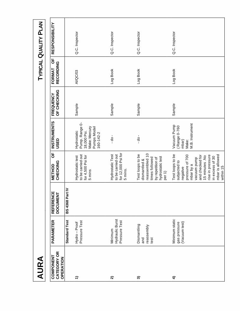
AU
RA
T
YP
ICA
L Q
UA
LITY
PLA
N
CO
MP
ON
EN
T C
ATE
GO
RY
OR
O
PE
RA
TIO
N
PA
RA
ME
TER
R
EFE
RE
NC
E
DO
CU
ME
NT
ME
THO
D
OF
CH
EC
KIN
G
INS
TRU
ME
NTS
U
SE
D
FRE
QU
EN
CY
O
F C
HE
CK
ING
FO
RM
AT
OF
RE
CO
RD
ING
R
ES
PO
NS
IBIL
ITY
S
tand
ard
Tes
t B
S 4
368
Par
t IV
1)
Hyd
ro –
Pro
of
Pre
ssur
e T
est
H
ydro
stat
ic te
st
to b
e ca
rrie
d ou
t fo
r 4,5
00 P
si fo
r 5
min
s
Hyd
rost
atic
P
ump.
Ran
ge 0
-18
,000
Psi
. M
ake:
Mer
cury
P
umps
Mod
el
160-
142-
2
Sam
ple
A
I/QC
/03
Q
.C. I
nspe
ctor
2)
Min
imum
H
ydra
ulic
Bur
st
Pre
ssur
e T
est
H
ydro
stat
ic T
est
to b
e ca
rrie
d ou
t fo
r 12,
000
Psi
for
5 m
ins.
- do
-
Sam
ple
Log
Boo
k Q
.C. I
nspe
ctor
3)
Dis
man
tling
an
d re
asse
mbl
y te
st
T
est l
oops
to b
e di
sman
tled
&
reas
sem
bled
10
times
follo
wed
by
repe
titio
n of
hy
dros
tatic
test
pe
r 1)
- do
-
Sam
ple
Log
Boo
k Q
.C. I
nspe
ctor
4)
Min
imum
sta
tic
gas
pres
sure
(V
acuu
m te
st)
T
est l
oops
to b
e su
bjec
ted
to
nega
tive
pres
sure
of 7
00
mba
r by
a
vacu
um p
ump
and
chec
ked
for
15 m
inut
es .N
o ri
se in
pre
ssur
e in
exc
ess
of 3
0 m
bar
is a
llow
ed
with
in 1
5
Vac
uum
Pum
p
( Ran
ge 0
-760
m
bar)
M
ake:
M
.B. I
nstr
umen
t
Sam
ple
Log
Boo
k Q
.C. I
nspe
ctor
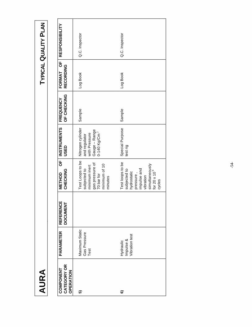
AU
RA
T
YP
ICA
L Q
UA
LITY
PLA
N
CO
MP
ON
EN
T C
ATE
GO
RY
OR
O
PE
RA
TIO
N
PA
RA
ME
TER
R
EFE
RE
NC
E
DO
CU
ME
NT
ME
THO
D
OF
C
HE
CK
ING
IN
STR
UM
EN
TS
US
ED
FR
EQ
UE
NC
Y
OF
CH
EC
KIN
G
FOR
MA
T O
F R
EC
OR
DIN
G
RE
SP
ON
SIB
ILIT
Y
5)
Max
imum
Sta
tic
Gas
Pre
ssur
e T
est
T
est L
oops
to b
e su
bjec
ted
to
min
imum
iner
t ga
s pr
essu
re o
f 70
bar
for
min
imum
of 1
0 m
inut
es
Nitr
ogen
cyl
inde
r an
d re
gula
tor
with
Pre
ssur
e G
auge
– R
ange
0-
140
Kg/
Cm
2
Sam
ple
Log
Boo
k Q
.C. I
nspe
ctor
6)
Hyd
raul
ic
Impu
lse
&
Vib
ratio
n te
st
T
est l
oops
to b
e su
bjec
ted
to
hydr
osta
tic
pres
sure
, im
puls
e an
d vi
brat
ion
sim
ulta
neou
sly
for
20 x
10
5 cy
cles
Spe
cial
Pur
pose
te
st r
ig
Sam
ple
Log
Boo
k Q
.C. I
nspe
ctor
-5
4-

,-:' " ,,';\0,"'" ".
~,
r"""'" ' 5~'"
'-'''',''
c, ,"1311mv'...--. -', .. , ,. ', . "..., ',.
. ,. .' > ..', " , , ..,. h
~"'G'" "
"
"
"'.'~
'
;:'
.
'~
,
(
,
'- .h
,,
~"'~"
,.
,
.;)
.
~,
""
"
"
.
"
"
"
""
".
,
.
., '
,
':, , ., '. '-
. .
@~...
.
"
[W'
,,
'
,
.', ',:., -
, ". . ,D " ", ,'-.
'.. ;.
. ' . .j,
, ..
c";",.,;;:., ;'C""'" ;E 'R"T"" ,
.
I
'
.
!i'
[F,., , :
B
"'
:-r
'
.,
'.
--~ ";f.' ~..., ,,:, . ,:". ,t ,;:.. '; '. .'
-- ~;;,;~ .>..If,, ~;ji". "'" ' , h ,," . ',;', , -; , :-
r 'k
,,". >,
, '.",'. .. "
,:,n'<:.,.t::".:~"'r ",',
.,,- '. ' -- ""-,j~,,.
.-."'(' '" .,'". ',J,
," . -',.
,',,' "
I .'''1,
"",,':<::'::.,,; Ih,eTOV"e,ER! Certlf.lcafion.., Bod:y~'-:':<7:~"~,fQr QM Systems of.RWTUV SY$te'ms G'mjbH ..
:,.,Ts;:~~:,:":~, herebycertifi'esinaccord~nce wifh'TtJVtERT;~f"; .~::,,:.~:"~, . procedure that' "
.',.,
,/ '
~\n; ~~::.:'"."'.;..~0AURA INC..::.,,~.:';~~'9~,j'Office':W-J6,7{A), Greater Kailas'h-'U, New Delhi...; 110 048"~
.~;~~ W'orks : D-ll/3, Okhla Industrial Area, Phase - It,~ ' -
,,' ,.!r.' 'New Delhi - 110 020 India',d..,e ... ",' "
" .
i,'
."" '
J
~.,::-~'i!~'~.:"::';'has established and appliesaqucHitysystem for- i., ,<-< '
.","~'" :~,' ."r.,
::. -",.~o,'Mc;m:vfac.tbteand sup'piy oflrlstrument'FitUngs, Valves and Manifolds,'''''1'' , ' ,"
:;"\.IJ~J~lp~rotVi~ SensingA'ccessories and"Pre.cisi6n Turnec;l 'Co~pone nls,r;,,,',.d!'t.-" ''-','
,'c~. -'.;'" -
0 ":,;jf.' .;.", ~ AnaliJdit,was performed,Report No.2.5-1463!20Ql,""''- - "- I "
" ~'~k --",Proof has been furnished-that the requirementsaccQrding to-,,',;, -. " --,-y" '.
-- -,.,
<~ ..ISO 9001:2000,,- '.~, .--I,'"
I _".1";>"t
"
are'fulfilled, The certificate is valid until 30 October2007
Ce'ttificateRegistrationNo. 0410020011698-E3
The companyhas been certifiedsince 2001
.,1f,',"
" ,'J.-
.,.ul '
., " '.,;
" ,"'I;'
"
Esseh, 10.12.2004 '~RWlUV ~Q~
ofRwrOV SystemsGmbH
'i.".
; ,'., "
",
'''''' <WTfN 2,00
IND,R
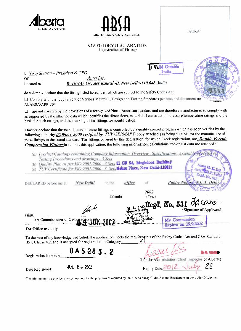

NORTH AMERICA
US Corporate Head Quarters Aura Inc.
3000 Bridge Parkway, Suite 101 Redwood Shores, CA 94065, USA
Voice: (650) 575 9672 Email : [email protected]
Sales & Distribution – North America
Aura Inc. 1146, Oakengate Road
San Dimas, CA 91773-3856, USA Voice: (909) 592 1102 Fax: (909) 394 1915
Toll Free: 1-877-AURAINC Email: [email protected]
ASIA
Corporate Head Quarters
Aura Inc. W-167 (A), Greater Kailash -II New Delhi - 110 048, INDIA
Voice: +91-11-41639515 / 16 Fax: +91-11-29210761
Email: [email protected]
Engineering, Manufacturing & International Sales Aura Inc.
D-11/3, Okhla Industrial Area, Phase-II, New Delhi – 110020 Voice: +91-11-55606848 / 49
Email: [email protected]
EUROPE
Aura Inc. Via Vertoiba 4
20137 Milano, Italy Telefax: +39 02 550 14360 Mobile : +39 335 664 7752
Email: [email protected]
www.aurainc.com