composite and different metallic bi-polar plates in … · paid to develop the cost-effective and...
TRANSCRIPT
IOSR Journal of Applied Chemistry (IOSR-JAC)
e-ISSN: 2278-5736.Volume 9, Issue 8 Ver. I (Aug. 2016), PP 79-106
www.iosrjournals.org
DOI: 10.9790/5736-09080179106 www.iosrjournals.org 79 |Page
Composite and Different Metallic Bi-Polar Plates in Proton
Exchange Membrane (PEM) Fuel Cells: Materials, Fabrication, Platings and Material Selection for Fuel Cells – A Review
Raja Vadivelan.M1, Dr.Ravi.S
2 Dr.Senthil Kumar.N
3,Dr.Kavitha.B
4
1Assistant Manager-Department of Refining, Titan Company Limited –Jewellery Division – Hosur, Tamilnadu,
India.635126. 2Head - Department of Chemistry, Karpagam University,Karpagam Academy of Higher Education , Coimbatore
, Tamilnadu ,India. 3Assistant Professor-Department of Chemistry,Arignar Anna Government Arts College, Cheyyar,
Tiruvannamalai District,Tamilnadu,India.Pin.604407. 4Associate Professor, Sri Ranganathar Institute of Engineering and Technology, Coimbatore-641110,
Tamilnadu, India.
Abstract: Proton exchange membrane (PEM) fuel cells offer exceptional potential for a clean, efficient, and
reliable power source. The bipolar plate (BP) is a key component in this device, as it connects each cell
electrically, supplies reactant gases to both anode and cathode, and removes reaction products from the cell.
BPs has primarily been fabricated from high-density graphite, but in recent years, much attention has been
paid to develop the cost-effective and feasible alternative materials. Recently, two different classes of materials
have been attracted attention: metals and composite materials. This paper offers a comprehensive review of the
current researches being carried out on the metallic and composite BPs, covering materials and fabrication
methods. In this research, the phenomenon of ionic contamination due to the release of the corrosion products
of metallic BP and relative impact on the durability as well as performance of PEM fuel cells is extensively
investigated. Furthermore, in this paper, upon several effective parameters on commercialization of PEM fuel
cells, such as stack cost, weight, volume, durability, strength, ohmic resistance, and ionic contamination, a
material selection is performed among the most common BPs currently being used. This material selection is
conducted by using Simple Additive Weighting Method (SAWM).
Highlights:
Materials, properties, Platings, Plating methods, stamping process and ionic contaminations of
metallic bipolar plates. Material selection upon eleven bipolar plate materials using the Simple Additive
Weighing Method (SAWM) approach.
Keywords: Metallic Bi-polar plate a n d Composite Bipolar plate. Different Platings of Precious and Non-
Precious on Metals to use it as Bi-Polar Plates Proton exchange membrane Fuel Cells.
I. An Introduction to PEM Fuel Cells: The global climate changes produced by greenhouse gases emissions such as CO2, NOx and SOx that
are ongoing throughout the world pose a progressively higher demand for replacing today’s fossil fuel based
energy production by less pollutant technologies [1,2]. Among the alternative energies available proton
exchange membrane (PEM) fuel cells have been considered to power transportation vehicles such as
automobiles and buses due to their high power density, relatively quick start-up, low operating temperatures and
low greenhouse gas emissions [3]. The use of lightweight metals for fuel cell bipolar plates is attractive for
automotive use. High corrosion resistance and electrical conductivity requirements for fuel cell components,
however, preclude most uncoated metals from use. Careful selection of alloy coatings and their constituents can
reduce or control the electrochemical corrosion potential and corresponding corrosion rate of the alloy coating.
New low-cost alloy coatings are being developed for Aluminium that possess the requisite high corrosion
resistance and high electrical conductivity. Our current development efforts include novel electrolytic alloys and
conductive polymer coatings for Aluminium to achieve desired fuel cell component lifetime goals. All main
vehicle manufacturers like General Motors, Ford, Toyota and Peugeot are developing fuel cell cars. Honda
launched the first commercial fuel cell car, the FCX Clarity, in the United States market during 2008 summer
[4]. Nevertheless, to completely achieve the automotive industry requirements PEM fuel cells have to overcome
some intrinsic limitations mainly related to durability and cost compared to conventional internal combustion
Composite And Metallic Bi-Polar Plates In Proton Exchange Membrane (PEM) Fuel Cells: Materials,
DOI: 10.9790/5736-09080179106 www.iosrjournals.org 80 |Page
engines [5]. Proton exchange membrane (PEM) fuel cells have attracted much attention recently due to the
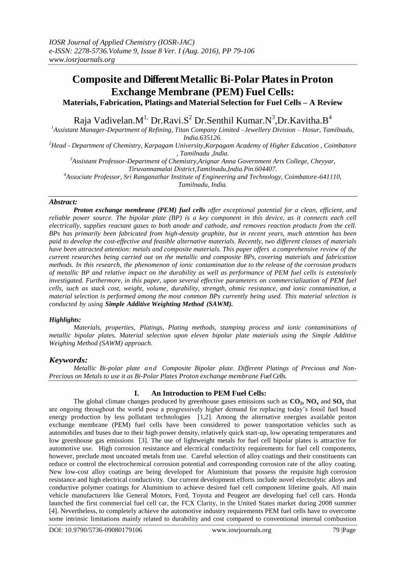
increasing awareness of Environmental factors and limited energy resources [1] (Fig. 1). PEM fuel cells are
devices that convert chemical energy of a fuel directly into electrical energy while allowing for high efficiency,
zero emission and low working temperature (70-90○C) compared to traditional power sources [2]. Thus, PEM
fuel cells are one of the most promising power sources in transportation applications, since the use of fossil fuel
and concomitant emission to the environment can be reduced [3]. However, currently PEM fuel cells are primarily
employed for research and demonstration applications due to remaining barriers of reliability, endurance, mass,
and cost that hinder their widespread commercial adoption [4].
Fig. 1. Schematic figure of PEM fuel cell components.
Bipolar plates (BPs) which are the key multifunctional component in PEM fuel cells constitute over
80% of the weight, 30% of the total cost and almost all of the volume in a typical fuel cell stack [5,6]. The
functions of BPs [6,7] include the following:
(1) Separating the individual fuel cells,
(2) Connecting the cathode side of one cell to the anode side of the other one with good conductivity,
(3) Feeding the reactive gases to the anode side (hydrogen gas) and cathode side (oxygen gas) via flow
channels,
(4) Removing the heat and reaction products (water).
Hence, high electrical conductivity, high gas impermeability, good mechanical performance, good
corrosion resistance and low cost are required for practical applications of BP materials [8]. Based on department
of energy (DOE) criteria [9,10], BPs should achieve some properties as follows:
Through-plane electrical conductivity >100 Scm—1;
Interface contact resistance (ICR) < 30 mUcm2 [11];
Chemical stability in the slightly acidic water pH < 4;
Corrosion resistance <16 mAcm—2 [11];
High thermal conductivity >10 W(mK)—1 [12];
Low permeability to hydrogen and oxygen <2 × 10—6 cm3(cm2s)—1 [11];
Flexural strength >59 MPa and
Impact strength >40.5 Jm—1 [11,12].
BPs has traditionally been fabricated from high-density graphite on account of its superior corrosion
resistance, chemical stability, high thermal conductivity and availability. However, due to its molecular
structure, it exhibits poor mechanical properties, high manufacturing cost, and it is difficult to work with. Never
the- less, graphite has established itself as the benchmark material for fabrication of bipolar plates, against
which all other materials are compared [1,6]. However, it is not suitable for either transportation applications that
require good structural durability against shock and vibration or large-scale manufacturing because of its poor
mechanical strength. The thickness of the graphite plates cannot be reduced, resulting in bulkiness and heaviness
[13]. As a result, recent studies have moved away from graphite in the direction of developing and optimizing more
cost effective materials such as metals and composites.
Composite And Metallic Bi-Polar Plates In Proton Exchange Membrane (PEM) Fuel Cells: Materials,
DOI: 10.9790/5736-09080179106 www.iosrjournals.org 81 |Page
Metallic materials are another choice for BPs because of their good mechanical strength, high
electrical conductivity, high gas impermeability, low cost, and ease of manufacturing [14-17]. The most
advantage of metallic BPs is stampability and reducing the thickness plate to about 1 mm. Stainless steel is
considered one of the promising candidates in BPs. On account of its self-passivating ability, stainless steel is
usually encapsulated by a passive film which can prevent the bulk materials from further corrosion. The
thickness of the passive film is typically in the range of 1-3 nm, which is affected by the environment and steel
grade. Although the passive film can decrease the corrosion rate of stainless steel, it will significantly increase ICR
between the BP and carbon paper [18]. In a PEM fuel cell, the stainless steel will also experience passivation, but
the thickness and the composition of the passive film will depend on the composition of the stainless steel and
the surroundings such as pH values, applied potential, and ions in the solution [8,14,18-20]. In addition, the
passive film will dissolve and reform when the environment conditions change leading to release metallic ions and
contamination.
Recently, polymer carbon composite BPs have been investigated due to their lower cost, less weight, and
higher corrosion resistivity in comparison with available materials such as graphite or metallic BPs [21]. The
disadvantages of composite BPs are non-stampability, lower electrical and mechanical properties than those of
metallic BPs. In this article, a review will be performed on the metallic and composite BPs in respect of materials,
properties, and fabrication methods. Since BPs must possess the combined advantages of both metals and graphite
composites in the fuel cell technology, various methods, and techniques are being developed to combat metallic
corrosion and eliminate the passive layer formed on the metal surface that causes unacceptable power
reduction and possible fouling of the catalyst and the electrolyte. The main objective of this study is to explore the
possibility of producing efficient, cost- effective and durable metallic BPs that were capable of functioning in
the highly corrosive fuel cell environment. In order to commercialize the PEM fuel cells, the BP type should
be selected based on the commercial parameters such as weight, volume, and performance. In the literature, a
comparative evaluation between the metallic and composite BPs focusing on commercial parameters has not yet been
performed.
There are some review papers on materials and manufacturing methods of BPs. Tibbetts et al. [22] in
many years ago (2007) has summarized the wide variety of composite properties and fabrication methods
achieved with vapor-grown carbon nano fiber /polymer composites. V. Mehta and J.S. Cooper [23] in many years
ago (2003) have been published one review on materials, fabrication, and coating methods of membrane electrolyte
assembly (MEA) and composite, graphitic, and metallic bipolar plates. S. Karimi et al. [24] recently (2012) were
investigated materials and fabrication methods of metallic bipolar plates. This paper offers a comprehensive
review of the current researches being carried out on metallic bipolar plates, covering materials and fabrication
methods. R. Sengupta et al. [25] in some years ago (2011) have published a review of the mechanical and electrical
properties of graphite and modified graphite reinforced polymer composites. Here, the blending and
polymerization methods of polymer-based carbon composite with an interest in nano fillers such as grapheme,
carbon nano tube, and expanded graphite were investigated. However, the main subject of this paper is general,
without regard to composites BP.
In the mentioned papers the ionic contaminations have not be investigated. In addition, a comparison
between composite and metallic BP from the viewpoint of commercialization interests (such as cost, volume,
weight, and durability) would be necessary. This paper reviews the last findings about materials (different
polymers and fillers used for composite BPs and different substrates and coatings used for metallic BPs) and
production methods (compression and injection molding in composite BPs and stamping and hydro forming
methods in metallic BPs), as well as ionic contamination were investigated. In this paper, a material selection is
also performed between metallic and composite BPs from the viewpoint of commercial parameters. M.C.
Oliveira et al. [26] recently (2012) employed the Ash by approach for selecting materials for the manufacturing
of bipolar plates for PEM fuel cells.
The selection process was divided into two distinct parts; material selection of polymer graphite
composite BPs and for metallic based ones. These routes were defined based on the different attributes relevant
to each type of material. The procedure was based on the development of a trade-off strategy based on the
evaluation of the corresponding Ashby charts. The approach is that different objectives should be defined for
different classes of materials (composite and metallic BPs), because the drawbacks of composite BPs is not
comparable with metallic BPs. The objectives for selecting polymer graphite composites are to maximize the
flexural strength and to maximize the electrical conductivity of the BP, while the objectives for selecting the
metallic bipolar plates are to minimize the corrosion current density and to minimize ICR.The material selection
is reasonable but in this method, there is not any comparison between composite and metallic BPs. On the other

Composite And Metallic Bi-Polar Plates In Proton Exchange Membrane (PEM) Fuel Cells: Materials,
DOI: 10.9790/5736-09080179106 www.iosrjournals.org 82 |Page
hand, only a limited number of objectives (electrical conductivity, ICR, corrosion current density, and flexural
strength) have been investigated. In this research, a material selection is performed among several commercial
composite and metallic BPs currently being used in the viewpoint of some commercial parameters include stack
cost, weight, volume, durability, flexural strength, ICR,corrosion current density, and ionic contamination. This
material selection was conducted by using a new approach upon simple additive weighting method.
II. Materials
BP materials are broadly divided into metallic and carbon-based BPs. Initially, carbon-based BPs,
particularly high-density graphite, dominated the R&D activities and other applications [24]. This stemmed
from the excellent chemical and electrical properties of graphite in the harsh operating PEM fuel cell
environment. However, its use was mainly limited to stationary and laboratory settings, where lightweight and
low volume plates were not critical. Additionally, the high cost of machining gas channels and the material’s
inherent brittleness retarded its use in terrestrial applications, including the mobile and transportation fields,
where cost-effective mass production processes are highly desired and often mandatory [27,30].
As a result, metallic BPs have recently attracted the attention of the scientific community. Metals
(excluding noble metals) may seem to exhibit most the desired characteristics, including high thermal and
electrical conductivity, low gas permeability, ease of manufacturing and relatively low cost. However, they have
a number of disadvantages such as chemical instability in the corrosive environments of PEM fuel cells, leading
to corrosion and the formation of a thin oxide layer on their surface. The former can poison the solid polymer
electrolyte as well as the catalyst layer by releasing corrosion by products (Fe3+,
Cr3+
, Ni2+,
etc.), while the latter
can significantly increase ICR between metallic plates and gas diffusion layers, resulting in inferior fuel cell
performance. A number of processes have been proposed to improve the corrosion resistance and ICR of
metallic BPs. These include the application of a thin, conductive protective layer on the surface of the metallic
plates as well as other surface modification techniques. In addition to a large number of publications on different
types of BPs, several review papers have been published on the material type, and manufacturing processes [22,
24, 31, 33]. In the next section, the state-of-the-art advances upon materials and fabrication are introduced.
2.1. Polymer-based Carbon Composite BPs
Usually these composites include two constituents; polymer as a binder (matrix) and filler as
reinforcing materials. In the next part, the polymers and fillers used for BPs are introduced.
2.1.1. Polymers
Both thermoplastic and thermo set resins may be employed in production of composite BPs [31,34].
Regardless of the nature of the polymer, the preparation of BPs requires a fairly large proportion of fillers, and
will eventually cause wetting problem [35]. If the difference in the surface energies between the polymer and
the fillers is low, then the polymer should efficiently wet the fillers, allowing an increase in the filler
concentration, before porosity appears in the composite. Dhakate et al. [36] also proposed that polymers
containing polar groups favour the conductive paths, thereby enhancing the electrical conductivity of the
composite [37]. The polymers applied for manufacturing BPs can be divided into two kinds; thermoset and
thermoplastic polymers. Here, the specifications of these polymers are reviewed.
2.1.1.1. Thermo sets
The components of thermo set usually include the resin, hardener, solvent, some additives such as
plasticizer, dispersant, and so on. Thermosets in comparison to thermoplastics usually have higher strength,
creep resistance, and lower toughness [38]. Thermosets are more brittle than thermo plasts. In high temperature
fuel cells, that fuel cell works at temperature as high as 120○C; thermosets can maintain their dimensional and
thermal stabilities better than thermoplastics. Another benefit of thermosets is that at temperatures higher than
glassing temperature, that curing process is initiated, the viscosity is lower than that of thermoplastics and thus
those can be loaded with higher level of conductive fillers. This fact aids in enhancing electrical conductivity,
mechanical strength and decreasing porosity of themoset based composites. Various types of thermoset resins
have been studied as possible matrix for composite BPs. Three types of thermosets are mostly described in the
literature for the fabrication of BPs: epoxy [39,40], phenolic [9,36,41-45] and vinyl ester [46-49]resins. Some
thermo set resins are liquid at room temperature (vinyl esters in styrene solution [49,50] and some resins are
dissolved in a solvent [10,36]). Epoxy resins are either as liquid or solid powder shape including a resin and
Composite And Metallic Bi-Polar Plates In Proton Exchange Membrane (PEM) Fuel Cells: Materials,
DOI: 10.9790/5736-09080179106 www.iosrjournals.org 83 |Page
hardener [51]. Phenolic resins which currently are more attractive to be used for BPs, are available in two
compositions; Resole and Novalac [9]. Novolac is produced by the reaction of formaldehyde with an excess
amount of a phenol or a phenol derivative in the presence of an acid catalyst. However, resole is produced by
the reaction of a phenol or a phenol derivative with an excess amount of formaldehyde in the presence of a base
catalyst. In novalac resin, in order to complete curing reaction, another agent such as hexa methylene tetramine
containing methylol groups is needed, however, for resole this extra agent is not necessary [52]. The different
natures of polymers (powder or liquid types) enable to apply various methods of processing, that each system
presents some advantages and disadvantages. The use of liquid resin enables the incorporation of high filler
content in composite. It should be noted that in the case of the powder form, usually no solvent is used but the
compound is often powdery shape and thus its moulding is difficult. Another disadvantage is the time cycle,
which can be very long, because a post-curing is often necessary to reduce the residual solvent content.
2.1.1.2. Thermo Plastics
Many authors have also investigated the use of thermoplastics for this application [50,53-57]. At first
glance, these materials seem less competitive, because they can commonly incorporate fewer amounts of fillers
than thermo set resins due to higher viscosity. However, a short cycle time associated with solvent free process
may overcome this drawback. Different thermoplastics have been tested for BPs applications and the most used
is polypropylene (PP) [50,53-57]. It combines a low cost, good processing conditions, and mechanical
properties. Poly vinylidene fluoride (PVDF) is also envisaged [37,58-62] because it shows a series of unusual
properties of interest for the applications: good barrier properties, chemical inertness, good mechanical
properties, and moisture resistance. Some studies concern poly phenylene sulfide (PPS) [63-68], which has good
mechanical properties and may be prepared with high filler contents. The other thermoplastic polymers used for
BPs are as follows: polyethylene [69], polyether ether ketone (PEEK) [70], polyethylene tetra phthalate
(PET) [63], poly phenylene oxide [71], nylon [72], and liquid crystalline [71,73].Thermo set polymers usually
escape some gases, during curing reactions, such as hydrogen, ammonia and H2O vapour. Therefore, during
preparation process of composite, the composite is better to be maintained under the high pressure for a long
time so that the produced gases can be released and gas pores can be closed as possible. The time and
temperature of this delay can be specified by the isothermal and non-isothermal analyses of Differential
Scanning Calorimetry (DSC) and Thermo-Gravimetry Analysis (TGA).Thermoplastics do not have curing
reactions, thus no gas porosity is created due to gas release. However to achieve a stable state, the die containing
thermoplastic composites should be cooled to below the glassing temperature of polymer.
2.1.1.3. Moulding Methods
In order to manufacture the composite BP, different methods have been applied. Slurry [42,74,75],Wet
Lay [43,67,76], solid-state shear pulverization [74], hot compression [38,77,81], and injection moulding
[54,71,82,84] methods are the common methods for producing the BPs. Typically hot compression moulding
seems to produce plates with higher electrical and thermal conductivity and dimensional stability [29].
However, successful injection moulding of BPs has been demonstrated. In injection moulding usually the die
cannot be maintained at high temperature under the constant pressure while, in the hot compression it is
possible. The maintaining of system at constant temperature and pressure is very critical for thermo set polymers
to remove the gases released from the curing of the polymer, thereby decreasing the composite porosity.
Another drawback of the injection molding is that the maximal filler content incorporated in the formulation is
much lower than that of compression molding. Because, in injection molding the viscosity should be so low that
the material can properly flow. The final properties of composite are strongly dependent on the processing
conditions and particularly on the flow direction in the mold. In injection molding, there is more preferred
orientation of fillers along the flow direction than compression molding. In contrast to compression moulding,
in injection molding some materials are wasted within the single or double-extruder die. Regarding the above
mentioned, the hot compression molding is still the most common method for the BP production, especially for
thermo set-based composite BPs.
2.1.2. Fillers
Polymers are commonly electrical insulators; therefore, the conductivity is enhanced by adding
conductive fillers. Two types of fillers may be considered, based on either metallic conductors, or the
derivatives of carbon. Although the metallic conductivity may be very high, most of studies in the literature
concern the carbon fillers. There are few studies [34, 85] (and references therein) concern BPs made of polymer-
based metal composite and this can be explained by the fact that this solution could hardly compete for this

Composite And Metallic Bi-Polar Plates In Proton Exchange Membrane (PEM) Fuel Cells: Materials,
DOI: 10.9790/5736-09080179106 www.iosrjournals.org 84 |Page
application. There are some limitations in combining the metal and polymer. In addition, low corrosion
resistivity and high density of metals can be mentioned as two major factors limiting the usage of metals in
composite BPs. The most common carbon fillers used for manufacturing composite BPs in literature are
graphite, expanded graphite, and carbon fibre (Fig. 2). Below, some common carbon fillers utilized in
manufacturing BPs are separately reviewed.
2.1.2.1. Graphite
The most commonly used BP material is graphite [78, 79, 86]. Graphite is the crystalline form of the
carbon, apart from Diamond and fullerenes. It exhibits either metallic properties, such as thermal and electrical
conductivities or non-metallic properties, such as inertness, high corrosion resistance, and lubricity. Usual
properties of graphite and other fillers are presented in Table 1. The graphite is micro-sized filler presenting a
low specific surface and an aspect ratio close to one and therefore induces little mechanical properties
improvement. Layered structure has a c-axis lattice constant of 0.66 nm and there are no reactive surface groups
on the graphite layers [36]. Fig. 2 a and b shows the morphology of pure graphite particles and fracture surface
of polymer/G composite, respectively. The electrical conductivity of P/G composites is rather high compared to
other carbon fillers. Graphite particle contains some graphene layers that connect together by weak wander
Waals bond. Therefore electrical conductivity of through-plane is very lower than in-plane of each graphite
particle. Electrical conductivity of graphite is in order of 104 Scm_1 at room temperature [36,87]. Graphite has
excellent corrosion resistance. However difficulty in machining and its brittleness is the biggest weakness of
graphite to be employed in BPs [88,90] that due to which, BP requires a thickness of the order of several
millimetres, and causes the fuel cell stack to be heavy and voluminous [42,91]. Graphite has also a very low
density about 2g/cm3.
2.1.2.2. Expanded Graphite
The natural graphite flakes could be intercalated by modification with various chemical species to form
the graphite intercalation compounds named expandable graphite. Conventionally, the expandable graphite is
heated in a muffe oven at a temperature higher than 800○C to produce the expanded graphite (EG) [92-94].
Recently, microwave irradiation is widely used to heat the expandable graphite, because it can provide a clean
and cheap alternative approach compared with the conventional heating method. The expandable graphite
subjected to only 30 s of microwave irradiation is expanded and exfoliated up to 200 times along the c-axis
direction (Table 1) [95]. Fig. 2 c and d shows the morphology of pure EG particles and fracture surface of
polymer/EG composite, respectively. The high expansion of EG induces a modification of spacing between
graphite layers, thereby a reduction of the density between 10_3 and 10_2 gcm_3, whereas the surface area and
mean aspect ratio may increase to 40 m2 g_1 and 15, respectively [21]. Moreover the electrical properties are
improved, since a conductivity of 12,500 Scm_1 is measured by Celzard et al. [92]. Further exfoliation in a
solvent leads to creating graphite nano platelets [7]. The “paper” materials based on graphite nano platelets
have been reported with conductivities as high as 350 Scm_1 [96] much above the needs for the BPs
applications. EG, in recent researches [25, 36, 41, 44, 97,109], has been widely employed in the composition of
composite BPs, because of its high electrical conductivity and its high aspect ratio that dramatically decreases
percolation threshold in composite BPs [41,110]. But increasing filler loading in composite BPs can
considerably decrease the mechanical strength; therefore the filler loading should be optimized by another filler
such as CF [79,110].
Composite And Metallic Bi-Polar Plates In Proton Exchange Membrane (PEM) Fuel Cells: Materials,
DOI: 10.9790/5736-09080179106 www.iosrjournals.org 85 |Page
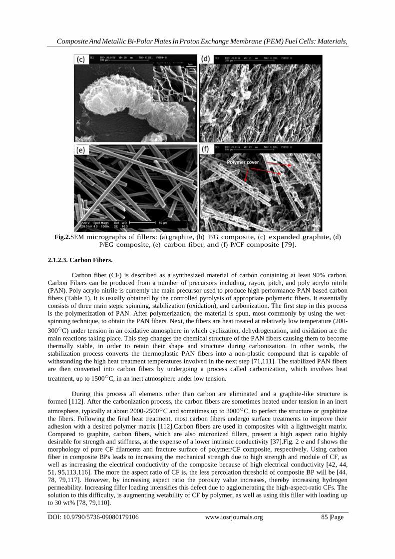
Fig.2.SEM micrographs of fillers: (a) graphite, (b) P/G composite, (c) expanded graphite, (d)
P/EG composite, (e) carbon fiber, and (f) P/CF composite [79].
2.1.2.3. Carbon Fibers.
Carbon fiber (CF) is described as a synthesized material of carbon containing at least 90% carbon.
Carbon Fibers can be produced from a number of precursors including, rayon, pitch, and poly acrylo nitrile
(PAN). Poly acrylo nitrile is currently the main precursor used to produce high performance PAN-based carbon
fibers (Table 1). It is usually obtained by the controlled pyrolysis of appropriate polymeric fibers. It essentially
consists of three main steps: spinning, stabilization (oxidation), and carbonization. The first step in this process
is the polymerization of PAN. After polymerization, the material is spun, most commonly by using the wet-
spinning technique, to obtain the PAN fibers. Next, the fibers are heat treated at relatively low temperature (200-
300○C) under tension in an oxidative atmosphere in which cyclization, dehydrogenation, and oxidation are the
main reactions taking place. This step changes the chemical structure of the PAN fibers causing them to become
thermally stable, in order to retain their shape and structure during carbonization. In other words, the
stabilization process converts the thermoplastic PAN fibers into a non-plastic compound that is capable of
withstanding the high heat treatment temperatures involved in the next step [71,111]. The stabilized PAN fibers
are then converted into carbon fibers by undergoing a process called carbonization, which involves heat
treatment, up to 1500○C, in an inert atmosphere under low tension.
During this process all elements other than carbon are eliminated and a graphite-like structure is
formed [112]. After the carbonization process, the carbon fibers are sometimes heated under tension in an inert
atmosphere, typically at about 2000-2500○C and sometimes up to 3000○C, to perfect the structure or graphitize
the fibers. Following the final heat treatment, most carbon fibers undergo surface treatments to improve their
adhesion with a desired polymer matrix [112].Carbon fibers are used in composites with a lightweight matrix.
Compared to graphite, carbon fibers, which are also micronized fillers, present a high aspect ratio highly
desirable for strength and stiffness, at the expense of a lower intrinsic conductivity [37].Fig. 2 e and f shows the
morphology of pure CF filaments and fracture surface of polymer/CF composite, respectively. Using carbon
fiber in composite BPs leads to increasing the mechanical strength due to high strength and module of CF, as
well as increasing the electrical conductivity of the composite because of high electrical conductivity [42, 44,
51, 95,113,116]. The more the aspect ratio of CF is, the less percolation threshold of composite BP will be [44,
78, 79,117]. However, by increasing aspect ratio the porosity value increases, thereby increasing hydrogen
permeability. Increasing filler loading intensifies this defect due to agglomerating the high-aspect-ratio CFs. The
solution to this difficulty, is augmenting wetability of CF by polymer, as well as using this filler with loading up
to 30 wt% [78, 79,110].

Composite And Metallic Bi-Polar Plates In Proton Exchange Membrane (PEM) Fuel Cells: Materials,
DOI: 10.9790/5736-09080179106 www.iosrjournals.org 86 |Page
2.1.2.4. Carbon black
Carbon black (CB) is another form of elemental carbon, which has to be synthetically produced (Table
1). It has traditionally been used as a pigment for inks, coatings, and paints, as well as an additive to reinforce
rubber products. There are five processes by which carbon blacks have been made: lampblack, impingement,
acetylene, thermal, and furnace processes. Today the majority of the carbon blacks are made by either the
furnace or the acetylene gas is introduced into a reactor that has been preheated to 800○C.
Table1: Physical and mechanical specifications of common carbon fillers used for
composite BPs. P.L: Particle Length; D: fiber Diameter; S.T: Sheet thickness.
P.L: Particle Length; D: fiber Diameter; S.T: Sheet thickness.
At this temperature, the acetylene undergoes exothermic decomposition and the reaction produces
temperatures at the carbon black surface in excess of 2500○C, with carbon black formation most likely taking
place in the 800-2000○C range. Acetylene blacks typically have intermediate particle size, relatively high
crystallinity (when compared to other carbon blacks) and very high structure. They also exhibit low reactivity
and have low surface oxygen. The properties of this carbon black have made it a popular choice for applications
that require chemical inertness or high electrical and thermal conductivity [3]. Carbon black is in the form of
pellets that are 100 mm to 2 mm in size. Upon mixing into a polymer, these pellets are easily separated into
primary agglomerates 30-100 nm long. This material efficiently imparts electrical conductivity at relatively low
filler loadings. This highly branched, high surface area carbon black structure allows it to contact a large amount
of polymer resulting in improved electrical conductivity at low carbon black concentrations [3]. Although based
on carbon, carbon black differs from graphite and carbon fibers; it is composed of aggregates having complex
configurations, quasi graphitic structure, and colloidal dimensions [118]. Compared to graphite or carbon fibers,
carbon black presents a complex morphology that could fill the holes left with the previous fillers. Carbon black
can be used in composition of composite BPs [44,51], however its low mechanical and electrical properties limit
its applications in commercial BPs.
2.1.2.5. Carbon Nano Tubes (CNT)
CNT is the carbon containing a tubular structure, 1-50 nm diameters, and 1 mm to few centimetres
length [119]. Consequently, their aspect ratio can be very large.CNTs can be found now in a commercial form
of multiwall (MWNT) or in the laboratories as single wall (SWNT) [120]. The nano tubes have induced a very
large scientific interest since their discovery, because of their unique physical properties. The main properties of
these fillers are presented in Table 1. With a very large elastic modulus, CNTs are known as effective
reinforcing agents. Depending on their molecular structures, CNTs with small diameters show either semi-
conducting or metallic behaviour. CNTs are substantially used in catalyst layer of PEM fuel cells as platinum
support sites. CNTs, due to high aspect ratio, can considerably ease the formation of conductive network,
thereby decreasing percolation threshold more than other fillers [86]. But, the CNTs are so expensive fillers that
cannot satisfy the DOE criteria related to BP cost (<5 $(kW)_1). However, this filler, due to high aspect ratio,
has a synergetic effect on other fillers, provided that the agglomeration of CNTs through the polymer can be
well controlled. Therefore, using this filler in low filler loading up to 1 wt% has been investigated [51,121,122].
Dhakate et al. investigated the improvement of the properties of polymer/G composite BPs by incorporating
nanostructure filler. This involves the incorporation of different vol % of MWNTs in graphite polymer
composite BPs. It has been found that by inclusion of 1 vol% of MWNTs in graphite composite plate, the
electrical and thermal conductivity of nano composite increased by 100%. Oliveira et al. [123] made a polymer-

Composite And Metallic Bi-Polar Plates In Proton Exchange Membrane (PEM) Fuel Cells: Materials,
DOI: 10.9790/5736-09080179106 www.iosrjournals.org 87 |Page
based composite by using graphite and MWNT. It was revealed that the corrosion current density (ICorr) of
composite in different CNT weight percentages was lower than DOE criteria (i.e. 1 mAcm_2). The
incorporation of 2 wt% of MWNTs provided the best compromise between through-plane electrical conductivity
and corrosion resistance. The formation of MWNT agglomerates can be responsible for depressing the
corrosion resistance and the electrical conductivity.
2.1.2.6. Graphene
Recently, graphene has attracted both academic and industrial interest, because it can produce a
dramatic Improvement in properties at very low filler content. The modification of graphene/graphene oxide and
the utilization of these materials in the fabrication of nano composites with different polymer matrices have
been explored [124-129]. Different organic polymers have been used to fabricate graphene-filled polymer nano
composites by a range of methods. In the case of modified graphene-based polymer nano composites, the
percolation threshold can be achieved at a very lower filler loading. Graphene is another allotrope of carbon in
which carbon atoms are arranged in a regular hexagonal pattern (Table 1). Graphene can be described as a
single-atom thick layer of the mineral graphite (many layers of graphene stacked together effectively form
crystalline flake graphite) [124]. Among its other well-publicized superlative properties, it is very light, with a
1m2 sheet weighing only 0.77mg.Graphene is extraordinarily strong (the strongest material ever known or
tested), supernaturally light, and electrically super conductive. But, the high production costs has limited its use
in BPs. Kakati et al. [130] used graphene as a minor filler in the Composition of composite BPs. The composite
of phenolic resin,64 wt% G, 5 wt% CB, 5 wt% CF, 1 wt% Graphene was found to be optimum for the
composite BPs. It was revealed that the reinforcement with 1% graphene significantly improved the electrical
conductivity of BPs. The properties of the graphene reinforced composite BPs fulfilled all the target values.
Therefore, due to high electrical conductivity and mechanical properties, it can be claimed that graphene is
superior filler for using in composite BPs. The only handicap of graphene is its high price. Table 1 shows the
physical and mechanical properties of different carbon allotropes commonly used for composite BPs.
2.1.3. Properties of Composite BPs
Polymer/Carbon composite is a promising alternative to both metal and pure graphite BPs, and has the
advantages of low cost, ease in machining or in situ moulding of complex flow fields during processing, good
corrosion resistance, and light weight [37,42,44,131]. Table 2 lists the composition, production method, and
properties of several polymer-based carbon composite BPs so far reported in the literature [231-234]. Mehta et
al. [23] have performed extensive studies on design and materials of PEM fuel cell, and reported the state-of-
the-art development of BPs by various processes. Mighri et al. [54] developed electrically conductive
thermoplastic blends for injection and compression moulding of BPs using carbon-filled PP and PPS. They
studied the properties of the BPs up to 60 wt% loading of the fillers (natural graphite, conductive carbon, and
CF). The BPs showed good flexural strength of around 50 MPa for PP samples and 84 MPa for PPS samples.
However, the electrical conductivity of the composite was below 1 Scm_1. Wolf and Porada [54] used liquid
crystal polymer (LCP) as binder and CB and CF as fillers to develop the composite. He claimed that the
developed composite has sufficient mechanical strength and low hydrogen permeability to be used as BPs.
However, the reported average electrical conductivity was only 5.6 Scm_1. Radha krishnan et al. [132] studied
the effect of processing conditions on the electrical properties of the BPs.
They used PPS and polyether sulfone (PES) as binder with natural graphite powder to prepare the
composite by compression moulding process. In the process, they used both solution blending and powder
mixing process. They reported that heat treatment of the samples at 100○C for few hours led to a significant
change in electrical conductivity of the samples. However, the reported electrical conductivity of the composite
was in the order of 10 Scm_1. Thus, they have suggested that a third additional conducting component may
provide high electrical conductivity of the composite. Yin et al.[133] studied the electrical and mechanical
properties of PF resin/graphite composite BPs and optimized the process conditions of the compression
molding. The best conductivity and bending strength of the plate were reported as 142 Scm_1 and 61.6 MPa,
respectively. This result was obtained in 15% resin content and compression molding at 240○C for 1 h. They
have also used nano fillers of CNTs to enhance the mechanical strength of the composite [134]. They reported
that reinforcement with 3% CNT improves the mechanical strength of the BPs from 50 to 68.6 MPa.

Composite And Metallic Bi-Polar Plates In Proton Exchange Membrane (PEM) Fuel Cells: Materials,
DOI: 10.9790/5736-09080179106 www.iosrjournals.org 88 |Page
Table2: Brief descript ion of materials and properties of different composite BPs reported in literature.
(Natural G/synthetic G/CB/CF)
Fig. 3. a) The schematic of a sandwiched composite bipolar plate,
b) SEM microstructures of the composite [80].
As the organic matrix is added to carbon-based fillers, the consequent increase of mechanical strength
is inevitably accompanied by a reduction of electrical conductivity. In this regard, a careful balance between
these two properties must be ascertained. Present article’s author [38,77-79,81] has conducted an in-deep study
on electrical conductivity and mechanical properties of phenolic resin/CF/G/EG composites. He investigated the
effect of each filler on the composite by adding 10-80 wt% of filler in single filler composites. In addition, he
found the synergetic effect of two fillers together by manufacturing double-filler and triple-filler composites.
Finally, he developed a new triple-filler composite that consists of phenolic resin, 45 wt % G, 10 wt % EG, 5 wt
% CF, and a thin CF cloth (Fig. 3). The results showed that this composite has flexural strength 74 MPa,
toughness 39 Jm_1, electrical conductivity 101 Scm_1, thermal conductivity >9 W(mK)_1, and porosity <5 vol
%. The author [80] assembled a single cell PEM fuel cell by this composite and achieved a maximum power
density 810 mWcm_2.
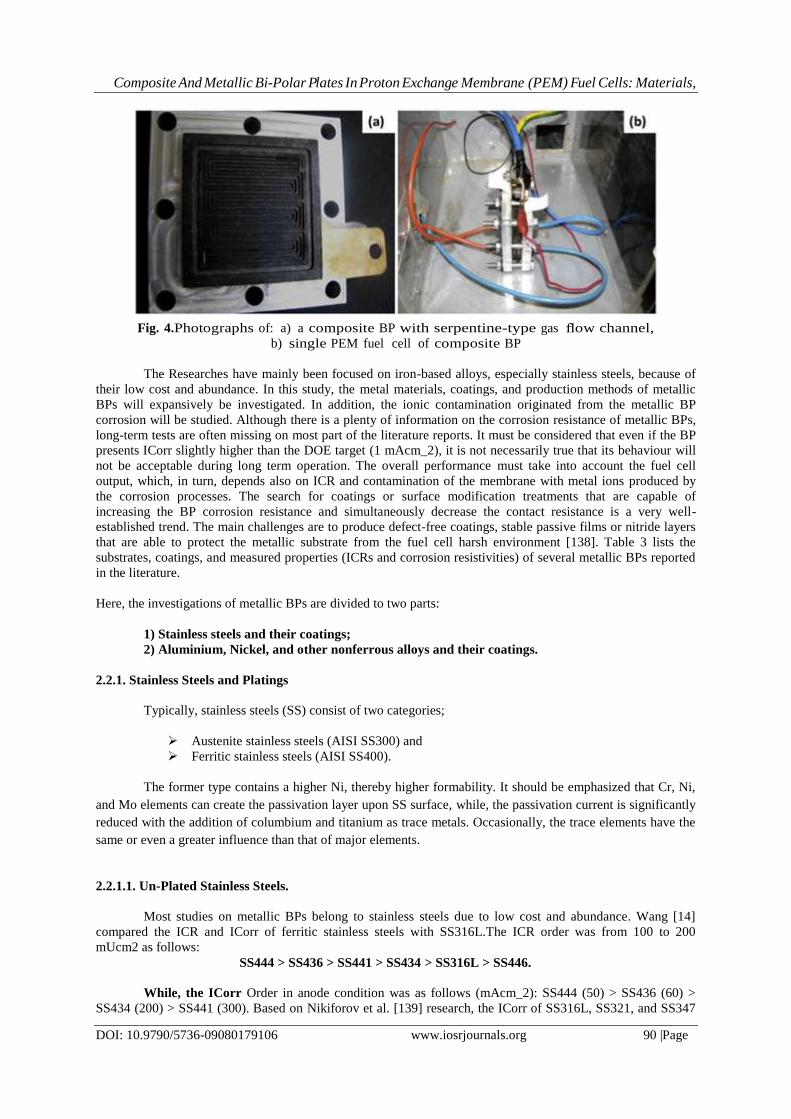
Fig.4 a and b exhibits the developed composite BP with serpentine type gas flow channels and the
assembled single cell during performance test, respectively. In addition, in another work [110] the author
introduced a new approach on electrical conductivity of polymer-based carbon composite by providing a new
equation that properly predicts the electrical conductivity of polymer based composites.Kinumoto et al. [135]
considered the thermal and electrochemical durability of carbonaceous composite plates made from graphite
powders and a resin in order to use in BPs. The results of TGA-DTA test under air up to 600○C showed a
significant weight loss over 300○C, but the hydro phobicity was decreased after heating at 80○C for 192 h. The
carbonaceous composite plates were electrochemically degraded under PEM fuel cell condition especially in
unitized regenerative fuel cell condition.

Composite And Metallic Bi-Polar Plates In Proton Exchange Membrane (PEM) Fuel Cells: Materials,
DOI: 10.9790/5736-09080179106 www.iosrjournals.org 89 |Page
2.2. Metallic Bi-Polar Plates
In recent years, metallic BPs have been attracting the attention of the research community because of
their desirable characteristics, such as high electrical conductivity, formability and manufacturability, gas
impermeability, and superior mechanical properties [8,136]. Metallic BPs offer higher strength, toughness, and
shock resistance than those of graphitic and composite BPs, and their excellent mechanical properties allow for
fabrication of thinner plates. Although, metals offer many advantages, they are more susceptible to corrosion,
which can adversely affect their performance and durability [24,137]. It is important to note that corrosion can
take place both at the anode and cathode of an operating PEM fuel cell. At the anode, the protective metal oxide
layer can be reduced as a result of the presence of a reducing environment, leading to unwanted hydride
formation and dissolution of the metal in water. This problem is amplified by the addition of water vapour to the
incoming fuel stream. This can potentially increase the risk of PEM contamination and can adversely affect the
activity of the catalyst layer. At the cathode, the existence of oxidizing environment can substantially increase
the corrosion rate of metallic BPs, leading to performance losses and even premature failure of the whole stack.
Up to now, several surface modification techniques have been proposed and various corrosion-resistant coatings
have been developed to minimize these effects [33]. So far, stainless steels, aluminium alloys, titanium alloys,
nickel alloys, copper alloys, and metal-based composites have been used in bipolar plate fabrication [24].
Composite And Metallic Bi-Polar Plates In Proton Exchange Membrane (PEM) Fuel Cells: Materials,
DOI: 10.9790/5736-09080179106 www.iosrjournals.org 90 |Page
Fig. 4.Photographs of: a) a composite BP with serpentine-type gas flow channel,
b) single PEM fuel cell of composite BP
The Researches have mainly been focused on iron-based alloys, especially stainless steels, because of
their low cost and abundance. In this study, the metal materials, coatings, and production methods of metallic
BPs will expansively be investigated. In addition, the ionic contamination originated from the metallic BP
corrosion will be studied. Although there is a plenty of information on the corrosion resistance of metallic BPs,
long-term tests are often missing on most part of the literature reports. It must be considered that even if the BP
presents ICorr slightly higher than the DOE target (1 mAcm_2), it is not necessarily true that its behaviour will
not be acceptable during long term operation. The overall performance must take into account the fuel cell
output, which, in turn, depends also on ICR and contamination of the membrane with metal ions produced by
the corrosion processes. The search for coatings or surface modification treatments that are capable of
increasing the BP corrosion resistance and simultaneously decrease the contact resistance is a very well-
established trend. The main challenges are to produce defect-free coatings, stable passive films or nitride layers
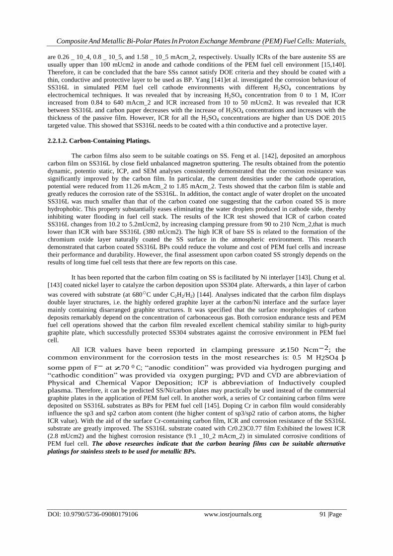
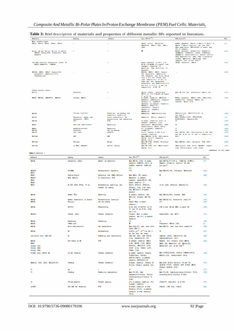
that are able to protect the metallic substrate from the fuel cell harsh environment [138]. Table 3 lists the
substrates, coatings, and measured properties (ICRs and corrosion resistivities) of several metallic BPs reported
in the literature.
Here, the investigations of metallic BPs are divided to two parts:
1) Stainless steels and their coatings;
2) Aluminium, Nickel, and other nonferrous alloys and their coatings.
2.2.1. Stainless Steels and Platings
Typically, stainless steels (SS) consist of two categories;
Austenite stainless steels (AISI SS300) and
Ferritic stainless steels (AISI SS400).
The former type contains a higher Ni, thereby higher formability. It should be emphasized that Cr, Ni,
and Mo elements can create the passivation layer upon SS surface, while, the passivation current is significantly
reduced with the addition of columbium and titanium as trace metals. Occasionally, the trace elements have the
same or even a greater influence than that of major elements.
2.2.1.1. Un-Plated Stainless Steels.
Most studies on metallic BPs belong to stainless steels due to low cost and abundance. Wang [14]
compared the ICR and ICorr of ferritic stainless steels with SS316L.The ICR order was from 100 to 200
mUcm2 as follows:
SS444 > SS436 > SS441 > SS434 > SS316L > SS446.
While, the ICorr Order in anode condition was as follows (mAcm_2): SS444 (50) > SS436 (60) >
SS434 (200) > SS441 (300). Based on Nikiforov et al. [139] research, the ICorr of SS316L, SS321, and SS347
Composite And Metallic Bi-Polar Plates In Proton Exchange Membrane (PEM) Fuel Cells: Materials,
DOI: 10.9790/5736-09080179106 www.iosrjournals.org 91 |Page
are 0.26 _ 10_4, 0.8 _ 10_5, and 1.58 _ 10_5 mAcm_2, respectively. Usually ICRs of the bare austenite SS are
usually upper than 100 mUcm2 in anode and cathode conditions of the PEM fuel cell environment [15,140].
Therefore, it can be concluded that the bare SSs cannot satisfy DOE criteria and they should be coated with a
thin, conductive and protective layer to be used as BP. Yang [141]et al. investigated the corrosion behaviour of
SS316L in simulated PEM fuel cell cathode environments with different H2SO4 concentrations by
electrochemical techniques. It was revealed that by increasing H2SO4 concentration from 0 to 1 M, ICorr
increased from 0.84 to 640 mAcm_2 and ICR increased from 10 to 50 mUcm2. It was revealed that ICR
between SS316L and carbon paper decreases with the increase of H2SO4 concentrations and increases with the
thickness of the passive film. However, ICR for all the H2SO4 concentrations are higher than US DOE 2015
targeted value. This showed that SS316L needs to be coated with a thin conductive and a protective layer.
2.2.1.2. Carbon-Containing Platings.
The carbon films also seem to be suitable coatings on SS. Feng et al. [142], deposited an amorphous
carbon film on SS316L by close field unbalanced magnetron sputtering. The results obtained from the potentio
dynamic, potentio static, ICP, and SEM analyses consistently demonstrated that the corrosion resistance was
significantly improved by the carbon film. In particular, the current densities under the cathode operation,
potential were reduced from 11.26 mAcm_2 to 1.85 mAcm_2. Tests showed that the carbon film is stable and
greatly reduces the corrosion rate of the SS316L. In addition, the contact angle of water droplet on the uncoated
SS316L was much smaller than that of the carbon coated one suggesting that the carbon coated SS is more
hydrophobic. This property substantially eases eliminating the water droplets produced in cathode side, thereby
inhibiting water flooding in fuel cell stack. The results of the ICR test showed that ICR of carbon coated
SS316L changes from 10.2 to 5.2mUcm2, by increasing clamping pressure from 90 to 210 Ncm_2,that is much
lower than ICR with bare SS316L (380 mUcm2). The high ICR of bare SS is related to the formation of the
chromium oxide layer naturally coated the SS surface in the atmospheric environment. This research
demonstrated that carbon coated SS316L BPs could reduce the volume and cost of PEM fuel cells and increase
their performance and durability. However, the final assessment upon carbon coated SS strongly depends on the
results of long time fuel cell tests that there are few reports on this case.
It has been reported that the carbon film coating on SS is facilitated by Ni interlayer [143]. Chung et al.
[143] coated nickel layer to catalyze the carbon deposition upon SS304 plate. Afterwards, a thin layer of carbon
was covered with substrate (at 680○C under C2H2/H2) [144]. Analyses indicated that the carbon film displays
double layer structures, i.e. the highly ordered graphite layer at the carbon/Ni interface and the surface layer
mainly containing disarranged graphite structures. It was specified that the surface morphologies of carbon
deposits remarkably depend on the concentration of carbonaceous gas. Both corrosion endurance tests and PEM
fuel cell operations showed that the carbon film revealed excellent chemical stability similar to high-purity
graphite plate, which successfully protected SS304 substrates against the corrosive environment in PEM fuel
cell.
All ICR values have been reported in clamping pressure z150 Ncm-2; the
common environment for the corrosion tests in the most researches is: 0.5 M H2SO4 þ
some ppm of F- at z70 o C; “anodic condition” was provided via hydrogen purging and
“cathodic condition” was provided via oxygen purging; PVD and CVD are abbreviation of
Physical and Chemical Vapor Deposition; ICP is abbreviation of Inductively coupled
plasma. Therefore, it can be predicted SS/Ni/carbon plates may practically be used instead of the commercial
graphite plates in the application of PEM fuel cell. In another work, a series of Cr containing carbon films were
deposited on SS316L substrates as BPs for PEM fuel cell [145]. Doping Cr in carbon film would considerably
influence the sp3 and sp2 carbon atom content (the higher content of sp3/sp2 ratio of carbon atoms, the higher
ICR value). With the aid of the surface Cr-containing carbon film, ICR and corrosion resistance of the SS316L
substrate are greatly improved. The SS316L substrate coated with Cr0.23C0.77 film Exhibited the lowest ICR
(2.8 mUcm2) and the highest corrosion resistance (9.1 _10_2 mAcm_2) in simulated corrosive conditions of
PEM fuel cell. The above researches indicate that the carbon bearing films can be suitable alternative
platings for stainless steels to be used for metallic BPs.
Composite And Metallic Bi-Polar Plates In Proton Exchange Membrane (PEM) Fuel Cells: Materials,
DOI: 10.9790/5736-09080179106 www.iosrjournals.org 92 |Page
Table 3: Brief description of materials and properties of different metallic BPs reported in literature.
Composite And Metallic Bi-Polar Plates In Proton Exchange Membrane (PEM) Fuel Cells: Materials,
DOI: 10.9790/5736-09080179106 www.iosrjournals.org 93 |Page
2.2.1.3. Chromium Containing Platings
Chromium Nitride (CrN) is one of the suitable and famous coating layers to be coated on stainless
steels, because it considerably decreases the ICorr and ICR [146,147].Park et al. [148] have studied on the
effects of a CrN/Cr coating layer on the durability of SS430 metal BPs under a fuel recirculation system of
DMFCs. It was revealed that the CrN/Cr coating layer decreased ICR from 2000 mUcm2 (for bare SS430) to 4
mUcm2 (for CrN/Cr coated SS430). ICorr was about 10_5 mAcm_2 in bare SS430 and 10_7e10_6 mAcm_2 in
coated one. Brady et al. [146,147,149] attempted to obtain low ICR and high corrosion resistance by nitridation
of Cr-bearing alloys, such as NieCr alloys and ferritic high-Cr stainless steels. CVD and PVD are two
economically favourable methods for making protective layers on stainless steel. Surface modification by
thermal nitridation is one of the solutions for decreasing ICorr and ICR of BPs to form a mixed nitride/Cr
nitride/oxide structure on the surface of the stainless steel [146,147]. However, high-temperature thermal
nitridation (about 900 _C) produces non-continuous and discrete external Cr-nitrides, thereby creating Cr-
depleted regions and decreasing corrosion resistance [150,151]. On the other hand, nitridation in high
temperature leads to creating the precipitates such as CrN, Cr2N and TiN, as well as Cr-depleted regions that is
more conductive than passive film (chromium oxide) [152,154]. It means that the nitridation in very high
temperature would decrease ICR.
Consequently, nitridation in high temperature is associated chiefly with the fact that the formation of
Cr-nitrides leads to a loss of Cr from the matrix, thereby reducing the corrosion resistance of stainless steels
[155,156]. However, un-continuous and discrete Cr-nitrides resulted from the nitridation at high temperature,
would have a positive effect on decreasing ICR, because inhibits the creating the continuous passive film
(chromium oxide phases). On the other hand, decreasing nitridation process temperature may severely decrease
atomic diffusion, decrease the coating thickness, and produce insufficient value of the precipitates such as CrN,
Cr2N and TiN. These can lead to increasing corrosion current density and ICR.Therefore, it is anticipated that
the temperature of nitridation should be optimized. There are few researches upon optimizing the nitridation
temperature, but some of these researches verify the mentioned statements. Below, some of these researches are
investigated. The results of research of Lee et al. [151] almost verify the mentioned claims. They performed
thermal nitridation in two temperatures (at 700○C and 900○C) on 446M stainless steel. They found that after
nitridation, ICR of stainless steel significantly decreased. They explained that nitridation leads to the formation
and exposure of Cr nitrides, such as the CrN, on the surface of stainless steel and these precipitates help reduce
the contact electrical resistance. In addition, the polarization curves revealed that the coated steel at 700○C has
excellent corrosion properties under PEMFC operating conditions, whereas the coated steel at 900○C has
relatively poor properties. They explained that the low temperature nitridation of stainless steel produces a
protective CrN/Cr2O3 layer, which protects the base metal from corrosive attacks. It was specified that ICR
value, ICorr in simulated anode condition, and ICorr in simulated cathode condition for nitrided SS446M at low
temperature is 6 mUcm2, 1 _ 10_6 Acm_2, and 1 _ 10_7 Acm_2, respectively, which are much lower than that
of the bare SS446M.
Tian et al. [157,158] reported that ICR could be reduced to 10 mUcm2 by plasma nitriding (at 370○C
for 2 h) of SS316L as well as SS304L, However ICorr was more than 10 mAcm_2 that is not acceptable. They
anticipated that conducting the coating process at high temperature (370○C) could lead precipitating more CrN
precipitates, thereby more extensive chromium depletion and lower corrosion resistivity. In an attempt, Hong et
al. [156] tried to optimize the temperature of nitriding process of SS316L. They performed the coating process
at different temperatures 257, 317, and 377○C by using inductively coupled plasma. It was revealed the least
value of ICR was achieved at 317○C (13mUcm2), whereas, the least value of corrosion current density was
achieved at 257○C (3.43 _10_6 Acm_2 at 0.6 V). These results verify this claim that the temperature of coating
process should be optimized to decrease either ICR or corrosion current density. It was revealed that using high-
density plasma nitiriding could reduce the process temperature, so that Cr depletion was not significant.
In another study, Yang et al. [159] clearly stated the advantages of low-temperature chromizing
treatment on SS316L (for 180 min at 900○C in Ar atmosphere) to produce mainly Cr-carbide and Cr nitride
coating. The substrates were pre treated by Shot peening to active surface and reduce chromizing temperature.
Results showed that chromized SS316L exhibits ICorr 3 _ 10_7 Acm_2 and ICR value 23 mUcm2 that are
respectively, about four orders and three times lower than those of bare SS316L. Bai et al. [160,161] used low-
temperature pack chromization to form a uniform and dense chromized coating on 1045 steel using a rolling pre
treatment.

Composite And Metallic Bi-Polar Plates In Proton Exchange Membrane (PEM) Fuel Cells: Materials,
DOI: 10.9790/5736-09080179106 www.iosrjournals.org 94 |Page
The results showed that the main constituent phases of the coating were carbides and the minor phases
were chromium-ferric nitrides and oxides. The maximum power density of the cell manufactured with this
metallic BP was higher than that of graphitic BP. It was concluded that the performance of chromized carbon
steels is comparable to that of graphite or noble metals for the application of BPs in PEM fuel cell. Furthermore,
the overall cost of chromized carbon steel BPs is much lower than that of graphite or noble metals. In another
work, Hung [5] studied on coating chromium carbide on aluminium and SS316 substrates. The results of the
study showed that chromium carbide coatings have relatively low ICR and moderate corrosion resistance in
comparison to other metals. In addition, the result of the 1000 h lifetime testing of a single cell containing
coated aluminium BPs, at cell temperature 70○C under cyclic loading condition, showed minimal power
degradation (<5%) due to metal corrosion [5]. Nam [162] investigated the electrochemical behaviour of multi-
coatings of CrN/TiN on SS316L. This study examined CrN/TiN coatings on SS316L deposited at three
thickness ratios of CrN/TiN by using RF-magnetron sputtering. The electrochemical studies indicated that
coating at CrN/TiN thickness ratio of 1:9 had very high protective efficiency 0.76 mAcm_2) [162]. Feng et al.
[3] co-implanted the Ni-Cr layer upon SS316L via ion implantation method and presented that ICR value
decreases from 380 (for as-received SS316L) to 200 mUcm2 (for NiCr-coated SS316L after polarization in
anode condition).Moreover, the ICP results showed that Fe is selectively dissolved in all cases.
2.2.1.4. Nitrogen-Containing Platings
One of the other most common coatings on stainless steels is TiN. Zhang et al. [163] investigated the
use of TiN-coated SS304 as BP. Two surface coating techniques, pulsed bias arc ion plating and magnetron
sputtering, are adopted to prepare the TiN-coated stainless steel. Both the TiN and Ti2N/TiN coatings provided
low ICR, 25 and 26 mUcm2, respectively, and low ICorr, 0.0131 and 0.0145 mAcm_2, respectively. However,
the long-term test is necessary for better validation. Yoon et al. [164] evaluated a number of protective coatings
deposited on stainless steel substrates (SS304, SS310, and SS316) by electroplating and physical vapor
deposition (PVD) methods. The coatings include Gold (2 nm, 10 nm, and 1 mm thicknesses), Titanium,
Zirconium, Zirconium Nitride (ZrN), Zirconium Niobium (ZrNb), and Zirconium Nitride with a Gold top layer
(ZrNAu). The results showed that Zr-coated samples satisfied the DOE target for corrosion resistance at both
anode and cathode sides in typical PEM fuel cell environments in the short-term. However, the ICR values of
bare SS316L (300mUcm2), Zr-coated SS (1000mUcm2), ZrN-coated SS (160 mUcm2), ZrNAu-coated SS (6
mUcm2), 2-nm-Au-coated SS (80mUcm2), 10-nm-Au-coated SS (4mUcm2), and 1-mm-Au-coated SS
(5mUcm2) indicated that although Zr is a suitable anti-corrosion coating, it greatly increases the ICR. Moreover,
Au or Au-containing coatings can beneficially reduce ICorr and ICR to lower than DOE criteria, provided that
the thickness of gold coating to be higher than 10 nm (particularly for the cathode side).The above results
indicate that CrN or nitrogen containing coatings, performed in the low temperatures, are two favourable
coatings upon stainless steel BPs of PEM fuel cells.
2.2.1.5. Ni-P Electro less Plating
One of the appropriate techniques for coating the layers on the BPs is an electro less plating method. In
order to increase corrosion resistivity, Ni-P coating on stainless steels is commonly utilized in industry.
Although, this coating method is very simple and just needs a homogenous solution bath at constant temperature
and pH, this method does not seem cost effective due to using the expensive organic materials [165]. It should
be emphasized that the thickness uniformity of coating for electro less method is more than that of other
methods such as electro plating. Lin et al. [166], employed electro less plating method to cover a Ni-P layer
upon SS316L. The potentio static test for the Ni-P deposits prepared under the optimal condition was performed
in a simulated anode working environment (0.5 M H2SO4 þ 10 vol % methanol). The test results showed a
negative corrosion current at all times indicating the cathodic protection of SS during the test. Even after 10 h
potentio static treatment, no metal ions were found in the test solution. In addition, the result of a performance
test demonstrated that stainless steel BPs coated by Ni-P layer obtained a lower bulk resistance and an enhanced
cell performance in comparison with commercially available plates. The Ni-P coating on SS316L by using Cu-
interlayer demonstrated a higher output current compared to the commercial PEM fuel cell, with w18% growth
in performance, but ICorr is higher than DOE criteria. Fetohi et al. [167] studied on coating of Ni-P and Ni-Co-
P on Aluminium alloy 5251 by electro less and electroplating methods. ICorr of Ni-Co-P coated plate was
improved by four times with respect of that at the bare AA5251 substrate. The least ICorr by electro less and
electroplating methods were related to Ni-Co-P (3.21 _ 10_5 Acm_2) and Ni-P (1.13 _ 10_7 Acm_2),
respectively. The electro less method resulted in an ICR value as high as 114 mUcm2 that is twice the amount of
that for coating by electroplating (54 mUcm2). The results of this research showed that Ni-P platings are not
suitable for usage in BPs.

Composite And Metallic Bi-Polar Plates In Proton Exchange Membrane (PEM) Fuel Cells: Materials,
DOI: 10.9790/5736-09080179106 www.iosrjournals.org 95 |Page
2.2.1.6. Noble-Metal Platings
Other compounds that are suitable to be coated on SSs in order to provide a conductive and protective
layer are noble metals such as gold, silver, and platinum. Silver is well known for its excellent electrical
conductivity, high corrosion resistance, and relatively low cost. Feng et al. [168] used ion implantation
technique for coating a thin layer silver on SS 316L. The potentio static tests revealed a significant decrease in
ICorr from 10 to 0.7 mAcm_2 after Ag implantation. In addition, the test showed that ICR value improved from
312 to 78mUcm2. The results showed that the overall reduction in ICR by ion implantation depends on the
value of precipitated silver nano particles in the implanted layer, the passive layer thickness, and amounts of
metallic phase of silver and nickel. In addition, the coating method, coating process conditions (especially
temperature), surface pre-treatment, and the coating thickness can obviously affect the coating quality, thereby
ICR value.
2.2.1.7. Other Platings
Feng et al. [169] investigated the corrosion behaviour and ICR of Nb-implanted SS316L. The
electrochemical results revealed that the passivation current density of the Nbim planted SS316L decreases in
the simulated PEM fuel cell environment (even lower than 1 mAcm_2). The ICP results showed that Nb-
implantation significantly reduces the dissolution rate. The depth profiles of XPS analysis indicated that a
passive film is formed with a new composition consisting mainly of niobium oxide. Our results suggest that Nb-
implantation with proper Nb concentration can significantly improve the corrosion resistance and the electrical
conductivity of SS316L in the simulated PEM fuel cell environments.In this study, the ICR test has not been
performed. Another idea in decreasing ICorr and ICR, is the doping of a special element on the surface layer to
modify the oxide layer conductivity and corrosion inhibition properties of the passive films. Lavigne et al. [170]
used the cerium element in order to dope into the SS316L surface, because this element either increases
electrical conductivity or increases corrosion resistivity of oxide layer [171,172]. They modified the steel
surface by maintaining the steel in a solution containing CeO8S2 and Na2SO4 for 2 h. The results showed that the
measured current densities of Ce-modified SS are much lower than DOE criteria. Furthermore, an important
diminution of ICR was obtained from 152 mUcm2 for SS316L to 33 mUcm2 for modified SS, which indicates
to this fact that cerium can increase charge carrier density in the passive film, thereby the passive layer
conductivity. However, to ensure the results the long term tests are necessary.
2.2.2. Non Ferrous alloy and Platings
Table 3 lists the substrates, coatings, and obtained results of the contact resistance and corrosion tests
for ferrous and nonferrous alloys studied in literature. Regardless of the price, it is predictable that the Ni-based
alloys such as Hastelloy, Incoloy and monel alloys are better candidates for metallic BPs than ferrous alloys,
because these alloys contain a higher corrosion resistivity and formability, as well as lower ICR than those of
ferrous alloys. However, Ni-based alloys usually are much more expensive than ferrous alloys and this limits
their application in commercial BPs. Aluminium alloys are suitable from the viewpoint of the cost, weight,
accessibility, and stampability. However, they have a weaker corrosion resistivity and mechanical strength in
comparison to SSs. Although titanium alloys have a lower weight, contain higher price, lower corrosion
resistivity, and lower stampability by comparison with SSs. As mentioned above, a comprehensive evaluation
needs to be provided considering all advantages and disadvantages of candidate materials for BPs.
2.2.2.1. Aluminium and Alloys
Barranco et al. [173] examined two Nitride Platings (CrN and ZrN) deposited on Al-based (Al-5083)
BPs via cathodic arc evaporation PVD. Potentio dynamic analysis showed that Al-CrN coated samples exhibit
better corrosion resistance than the ZrN/CrN coatings at the anode and cathode simulated environments.
Typically, the multilayer-coated BPs seems to become more fragile than the monolayer of that. One of the paths
to decrease corrosion rate of metallic BPs is the coating of metals by a thin polymer-based composite layer. Lee
et al.[174] developed an Al-based BP coated with a thin layer of polypropylene/carbon black composite. They
used carbon paper and CB as interlayer to decrease ICR between composite and Al layer. They reported the ICR
value lower than 21 mUcm2 and ICorr lower than1 mAcm_2 after a long time. However, the bond strength
between layer and substrate is doubtful. On the other hand, the high thickness of composite BPs increases
volume and weight of the stack.Mawdsley et al. [175] also coated polymer-based composite on Al by wet
spraying followed by heat treatment. The composite contains ethylene tetra fluoro ethylene as polymer and TiC
and graphite powders as fillers. In-plane electrical conductivity, cathodic corrosion resistance, flexural strength,
Composite And Metallic Bi-Polar Plates In Proton Exchange Membrane (PEM) Fuel Cells: Materials,
DOI: 10.9790/5736-09080179106 www.iosrjournals.org 96 |Page
and flexibility tests related to the aluminium plate showed that the composite coated aluminium plates met the
DOE targets for BPs. The targets for through-plane area specific resistance and anodic corrosion resistance were
not met DOE targets due to the spraying process producing an undesirable layered microstructure and also a
microstructure with connected porosity and pinholes.
2.2.2.2. Nickel based Alloys.
Brady et al. [147] have studied three commercial alloys namely, Hastelloy G-30 (Ni=30%;Cr=15%;Fe=
5.5%;Mo=2.5%;W=5%;Co=2%;Cu=1.5%;Nb), Hastelloy G-35 (Ni=33.2%;Cr=8.1%;Mo=2%Fe) and AL29-4C
(Fe=29%Cr=4%;Mo=0.3%;Ni=0.5%(Ti þ Nb)). Nitridation of the commercial Ni-Cr base alloys G-30 and G-
35, and the ferritic stainless steel AL29-4C, resulted in a significant reduction in ICR values, in the range of 10
mUcm2 (at 150 Ncm_2).Nitridation also yielded corrosion resistant surfaces, with anodic current densities less
than 1 mAcm_2 up to 0.9 V. It was possible to form semi-continuous CrN surface layers on G-30, G-35, and
AL29- 4C by nitridation. It seems that the only drawback of this commercial metallic Bps is their high price that
limits their applications.Nikiforov et al. [139] investigated the corrosion resistance of some bare metals. It was
revealed that the ICorr of SS316L, SS321,SS347, Inconel625, Incoloy825, HastelloyC-276, Tantalum, and Ti
were 26, 8,15.8, 4, 6.4,4.8,1.26 _10_2, and 1260 mAcm_2 (at 120○C),respectively. The results for SS316L,
SS321, SS347, Inconel625,Incoloy 825, and HastelloyC-276 at 80○C were 12.6, 20, 50, 0.1, 4, and 0.8
mAcm_2, respectively. It can be seen at 120○C only Ta, and in at 80○C Inconel 625 and Hastelloy C-276 can
satisfy the DOE criteria (1 mAcm_2). Ta has the best corrosion resistivity, but this metal is very expensive, that
is beyond the DOE criteria. HastelloyC-276 and Inconel 625 are the suitable metals for BPs. It should be
emphasized that in the viewpoint of commercial parameters, the stainless steels especially SS316L are the best
candidates for BPs due to lower price and more abundance. The formability of SS316L is higher than other
metals such as Ti that this property helps to stampability. However, this metal needs to be coated by high
conductive and corrosion resistance materials.
2.2.2.3. Titanium Alloys
Titanium is a lightweight metal (density 4.51 g cm_3), with hexagonal close packed (HCP) structure,
that is naturally coated with a non-conductive oxide layer. It should be emphasized that in comparison to other
metals with FCC structure (e.g., Ni and SS316L), Ti has a lower formability, thereby weaker stampability [176].
In addition, the non-conductive oxide layer coated on the Ti surface considerably increases ICR. Researchers
have attempted to improve the Ti performance by coating the conductive and corrosion resistance layers
[176,177]. In an attempt [177], Tie Ag film was coated on Ti substrate by pulsed bias arc ion plating method
that resulted in ICR as low as 4.3 mUcm2. ICorr of Ti/TieAg was approximately 10 mAcm_2 that is higher than
DOE criteria. Feng et al. [178] conducted low (100○C) and high temperature (370○C) nitrogen plasma
immersion ion implantation to improve the corrosion resistance and ICR of titanium sheets. Icorr and ICR for
different samples are as follows: bare Ti (1.45 mAcm_2 and 82 mUcm2), high-temperature-coated Ti (0.22
mAcm_2 and 12 mUcm2), and low-temperature-coated Ti (0.86 mAcm_2 and 440 mUcm2). It can be seen that
the low-temperature-coated Ti samples exhibited poorer corrosion resistance and interfacial contact conductivity
than the untreated titanium. These phenomena can be related to high porosity content between layer and
substrate at low-temperature-coating process. In addition, these data should be verified by long-term test.
2.2.3. Stamping and Hydro forming of Metallic BPs
Nowadays, the metallic sheet BPs with sustainable coating are promising candidates to replace
conventional graphitic, polymer based composite, or machined thick metallic plates due to their ability to be
stamped up to very low thickness as low as 0.051 mm [176,179,181]. Another advantage of the metallic BPs is
that those can be welded by laser welding process [182,183]. The stamping and hydro forming processes are two
viable solutions for mass production of micro-channel arrays on large thin plates to fabricate BPs for PEM fuel
cell applications [176,184]. Fig. 5 compares the method of performing these processes together. However, the
stamping or hydro forming processes accompany two main defects:
1) Rupture of material during forming process;
2) Uneven flow distribution in practical operation.
The depth of the slot on the channel rib should be optimized to eliminate the uneven flow distribution
and to obtain high reaction performance. In one research work, Peng et al. [184] found that the depth of the slots

Composite And Metallic Bi-Polar Plates In Proton Exchange Membrane (PEM) Fuel Cells: Materials,
DOI: 10.9790/5736-09080179106 www.iosrjournals.org 97 |Page
is more sensitive to the flow distribution. Flow distribution could be achieved by the optimization design of the
depth of slots. Large upper transition radius and draw angle of the die design could relieve contraction force,
avoid sheet rupture, and improve the formability of BP. The stamping and hydro forming processes have low in-
plate and between-plate variations with the maximum variation of less than 4.1% and 3.4% for stamping and
hydro forming processes, respectively [176]. The hydro formed BPs generally yield lower surface roughness
values at the channel peaks when compared to the stamped BPs. In addition, hydro forming provides BPs with
lower dimensional variations than the stamping process [176]. Two issues should be figured out during the
micro forming process and high production rate of BPs. One issue is the dimensional error resulted from
manufacturing technology [185,186] controlled by tools adjustment and amendments on process parameters
[176,183,187]. The other one is the shape error due to springbuck in stamping process, thermal stress in welding
process, on-uniform clamping pressure, and flexibility of ultra thin sheet [24,182,188,189]. In fact, a proper and
uniform pressure distribution on GDL is essential for PEM fuel cell operation. Both the dimensional error and
the shape error contribute to uneven assembly stress distribution, thereby uneven flow distribution affects the
contact performance between BP and GDL. Dimensional error, including height variations of channels and ribs,
surface roughness, and so on, has drawn wide attention. Mahabunphachai et al. [190] addressed the formability,
surface topography, and dimensional quality of metallic BPs fabricated by stamping and hydro forming
technologies.
Fig. 5. The schematic of stamping and hydro forming processes.
They claimed that hydro forming provides BPs with lower dimensional variations. In another study
[191], they pointed out that both channel spacing and channel number have considerable impact on the hydro
formability of multi-channels. Pekeret al. [192] investigated the variation of surface topography during long-run
micro-stamping of BPs, and established a relationship between surface topography and the change of contact
corrosion resistance. The attempts of Avasarala and Haldar [193,194] indicate that the impact of BP’s surface
topography on the ICR between BP/GDL interfaces is significant. Liu et al. [194] reported the effect of
dimensional error including the height of BP channels and ribs on GDL pressure distribution in the PEM fuel
cell. Indeed, coating materials, coating techniques, and the sequence of the coating process (i.e., coating before
or after forming process) affect the corrosion resistance [195]. Dur et al. [196] found that mean Icorr of SS316L
for un-deformed, hydro formed, and stamped samples changes from 7, 8, to 9 mAcm2. Mahabunphachai et al.
[176] showed that the stamping and hydro forming process affect the corrosion characteristics of the deformed
plates. This study reported that the corrosion resistance decreases with decreasing stamping speed and
increasing hydro forming pressure rate. The results showed that the manufacturing processes (i.e., stamping and
hydro forming) would generally degrade the corrosion resistance when compared to un deformed blanks [195].
It was observed that specifically the lower stamping speed results in more surface scratches and damages, which
in turn, gives the decrease in corrosion resistance [195]. The surface treatment before coating can substantially
affect bonding strength and coating life [197]. Yun [197] found that treatment of the metallic plates by electro
polishing prior to deposition of a surface metal coating is very effective at inhibiting corrosion. Results showed
that the electro polished stainless steel plates experience almost no chemical dissolution, while the mechanically
polished steel plates undergo significant degradation. Brady et al. [198] have studied on many commercial BPs
such as Hastelloy G-30, G35, SS 2205, 316L, etc. They reported that austenitic SS have a higher stampability
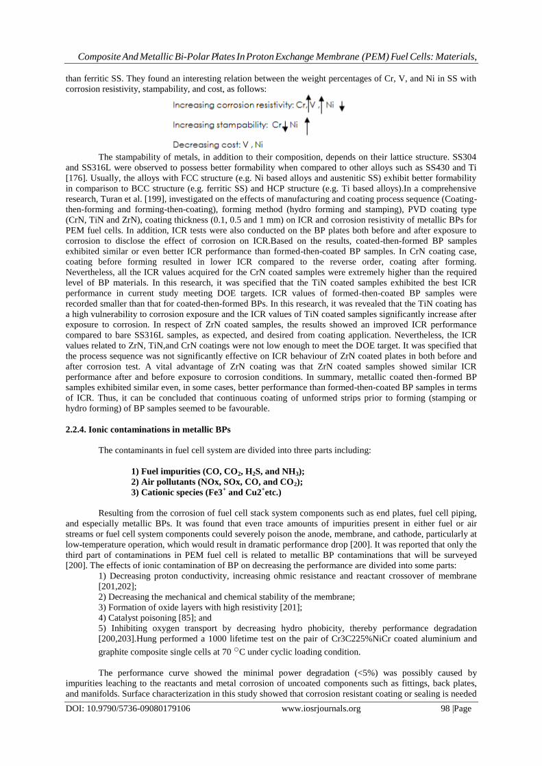
Composite And Metallic Bi-Polar Plates In Proton Exchange Membrane (PEM) Fuel Cells: Materials,
DOI: 10.9790/5736-09080179106 www.iosrjournals.org 98 |Page
than ferritic SS. They found an interesting relation between the weight percentages of Cr, V, and Ni in SS with
corrosion resistivity, stampability, and cost, as follows:
The stampability of metals, in addition to their composition, depends on their lattice structure. SS304
and SS316L were observed to possess better formability when compared to other alloys such as SS430 and Ti
[176]. Usually, the alloys with FCC structure (e.g. Ni based alloys and austenitic SS) exhibit better formability
in comparison to BCC structure (e.g. ferritic SS) and HCP structure (e.g. Ti based alloys).In a comprehensive
research, Turan et al. [199], investigated on the effects of manufacturing and coating process sequence (Coating-
then-forming and forming-then-coating), forming method (hydro forming and stamping), PVD coating type
(CrN, TiN and ZrN), coating thickness (0.1, 0.5 and 1 mm) on ICR and corrosion resistivity of metallic BPs for
PEM fuel cells. In addition, ICR tests were also conducted on the BP plates both before and after exposure to
corrosion to disclose the effect of corrosion on ICR.Based on the results, coated-then-formed BP samples
exhibited similar or even better ICR performance than formed-then-coated BP samples. In CrN coating case,
coating before forming resulted in lower ICR compared to the reverse order, coating after forming.
Nevertheless, all the ICR values acquired for the CrN coated samples were extremely higher than the required
level of BP materials. In this research, it was specified that the TiN coated samples exhibited the best ICR
performance in current study meeting DOE targets. ICR values of formed-then-coated BP samples were
recorded smaller than that for coated-then-formed BPs. In this research, it was revealed that the TiN coating has
a high vulnerability to corrosion exposure and the ICR values of TiN coated samples significantly increase after
exposure to corrosion. In respect of ZrN coated samples, the results showed an improved ICR performance
compared to bare SS316L samples, as expected, and desired from coating application. Nevertheless, the ICR
values related to ZrN, TiN,and CrN coatings were not low enough to meet the DOE target. It was specified that
the process sequence was not significantly effective on ICR behaviour of ZrN coated plates in both before and
after corrosion test. A vital advantage of ZrN coating was that ZrN coated samples showed similar ICR
performance after and before exposure to corrosion conditions. In summary, metallic coated then-formed BP
samples exhibited similar even, in some cases, better performance than formed-then-coated BP samples in terms
of ICR. Thus, it can be concluded that continuous coating of unformed strips prior to forming (stamping or
hydro forming) of BP samples seemed to be favourable.
2.2.4. Ionic contaminations in metallic BPs
The contaminants in fuel cell system are divided into three parts including:
1) Fuel impurities (CO, CO2, H2S, and NH3);
2) Air pollutants (NOx, SOx, CO, and CO2);
3) Cationic species (Fe3+ and Cu2
+etc.)
Resulting from the corrosion of fuel cell stack system components such as end plates, fuel cell piping,
and especially metallic BPs. It was found that even trace amounts of impurities present in either fuel or air
streams or fuel cell system components could severely poison the anode, membrane, and cathode, particularly at
low-temperature operation, which would result in dramatic performance drop [200]. It was reported that only the
third part of contaminations in PEM fuel cell is related to metallic BP contaminations that will be surveyed
[200]. The effects of ionic contamination of BP on decreasing the performance are divided into some parts:
1) Decreasing proton conductivity, increasing ohmic resistance and reactant crossover of membrane
[201,202];
2) Decreasing the mechanical and chemical stability of the membrane;
3) Formation of oxide layers with high resistivity [201];
4) Catalyst poisoning [85]; and
5) Inhibiting oxygen transport by decreasing hydro phobicity, thereby performance degradation
[200,203].Hung performed a 1000 lifetime test on the pair of Cr3C225%NiCr coated aluminium and
graphite composite single cells at 70 ○C under cyclic loading condition.
The performance curve showed the minimal power degradation (<5%) was possibly caused by
impurities leaching to the reactants and metal corrosion of uncoated components such as fittings, back plates,
and manifolds. Surface characterization in this study showed that corrosion resistant coating or sealing is needed
Composite And Metallic Bi-Polar Plates In Proton Exchange Membrane (PEM) Fuel Cells: Materials,
DOI: 10.9790/5736-09080179106 www.iosrjournals.org 99 |Page
to be applied upon manifolds, inlets, and outlets where the aluminium is not covered by the thermal spray
coating, because humidified reactant gases can oxidize the aluminium and carry aluminium oxide particles to
other areas of the cell. EDX analysis of this study showed the possibility of partial dissociation of Ni from the
Cr3C2-25% NiCr coating which indicated that less Ni is preferred in the corrosion resistant coating.
The metallic BP contaminations and their effects on performance during lifetime tests have been
investigated by other researches [53, 85,143,148,200-202,204-216]. Wind et al. [11] investigated the effects of
coating materials on reducing metallic ions in membrane electrolyte assembly (MEA). Strong acidic
environment in PEM fuel cell stemming from per fluoro sulfonic acid membrane dissociates metal ions, e.g., Fe,
Cr and Ni ions, from metallic BP to contaminate polymer electrolyte and Pt catalyst. The decrease in proton
conductivity and catalyst activity eventuate in the collapse of PEM fuel cell performance [143]. Sulek et al.
[204] investigated four ions including Fe, Ni, Cr (as the major elements in stainless steel BPs [205]), and Al (as
the cheapest and lightest metallic BPs). Metal ions were provided by using the solutions of hydrated metal
sulfates,FeSO4, NiSO4, Cr2 (SO4)3 and Al2(SO4)3. The membranes were contaminated with metal ions by
immersing the membrane in the metal ion solution for 24 h with stirring. The ranking of the four transition
metals tested in terms of the greatest reduction in fuel cell performance was as follows: Al3+ >>Fe2
+ > Ni2
+,
Cr3+.
In another research [213], Ni-50Cr alloy (with and without CrN plating) and SS316L were subjected to
4000 h lifetime test under the anodic and cathodic conditions. The results showed no increase in ICR and also
little dissolution of coated Ni-50Cr (w3 ppm Ni). It was revealed that the ICR of Ni-50Cr, nitrided Ni-50Cr, and
SS316L were 25, 7, and 90 mUcm2, respectively in clamping pressure of 150 Ncm_2. Cheng et al. [200] in a
review paper outlined all sources of membrane contamination. Collier et al. [207] cited the presence of Fe3+,
Cu2+ and other cations in a unit cell MEA after 10,000 h of operation. They mentioned that almost all cations
exhibit higher affinity to the sulfonic groups in the polymeric membrane than Hþ.When other cations exchange
for protons in the polymer structure, the amount of water in the cell is reduced. Kelly et al. [208,209]
investigated the influence of Fe3+, Cu2
+ and Ni2
+ concentration (in ppm) on the Nafion membrane conductivity.
A little effect was observed for up to 10 ppm of the ionic species. There was a huge drop of membrane
conductivity when the cation concentration reached 100 ppm. This effect was most intense for Fe3þ
contamination. This behaviour was explained through the findings of Okada et al. [210]. They stated that
membrane dehydration is caused by the lower hydrophilicity of cationic impurities in comparison to Hþ.The
foreign ion displaces one Hþ for each charge on its structure. Consequently, its mobility is lower than that of
Hþ, accounting for a further decrease of ionic conductivity. This mechanism was depicted in a study of Shi and
Anson [211].
They conducted a series of Experiments with many different cations replacing protons in Nafion
structure. Suitable coating such as nitriding can properly decrease the metallic-ion dissolution. Brady et al. [212]
studied on nitriding the surface of Fe-23Cr-4V alloy. Stable high frequency resistance behaviour was observed
over the course of 500 h single-cell fuel cell testing at 0.3 Acm_2. Post-test analysis of the MEAs indicated low
levels of metal ion contamination, less than 1 mgcm_2. Undoubtedly, the long-term-test of the metallic BPs in
PEM fuel cell environment, can so much better clarify durability status of them. Mele et al. [214] performed a
long-term test (1000 h of operation of a single-cell PEM fuel cell on both anodic and cathodic conditions) to
exhibit localized corrosion effects at the interface with the rubber gasket and the C-paper GDL, apparently due
to material coupling and type of gas feed. They observed severe localized attack developed at the cathodic BP.
They also indicated the peculiar localized corrosion effects, that can be described as crevice corrosion, resulting
from the coupling SS304 to carbon-based GDL. In this research, the impact of typical ionic contaminants (Cl_
and F_) on crevice corrosion has been investigated too. It was revealed that Cl_ions are found to be the most
aggressive in terms of crevice corrosion, whereas the effect of the F_ on crevice corrosion is negligible in the
absence of Cl_ and exhibits an inhibiting action in its presence, yielding narrower current density loops and
more anodic protection potential values. As far as ion effects are concerned, the same ranking was found to
apply both in the absence and in the presence of a crevice-former, regardless of the material it consists of Park et
al. [205] showed that the corrosion test results in the short term can differ from the long term (1074 h)
performance test in a real cell. In this research, a comparison between SS430 and SS316L was performed in the
viewpoint of the performance curve, over-potential values (consisting of activation, ohmic, and concentration),
water contact angle (indicating the water remaining in cathode side), and ion contamination. It was revealed that
although SS430 has a lower corrosion resistance than SS316L, SS430 has a lower over-potentials and
contamination, higher water contact angle and higher maximum power density than those of SS316L in both the
short and long-term-performance tests of the real cell.
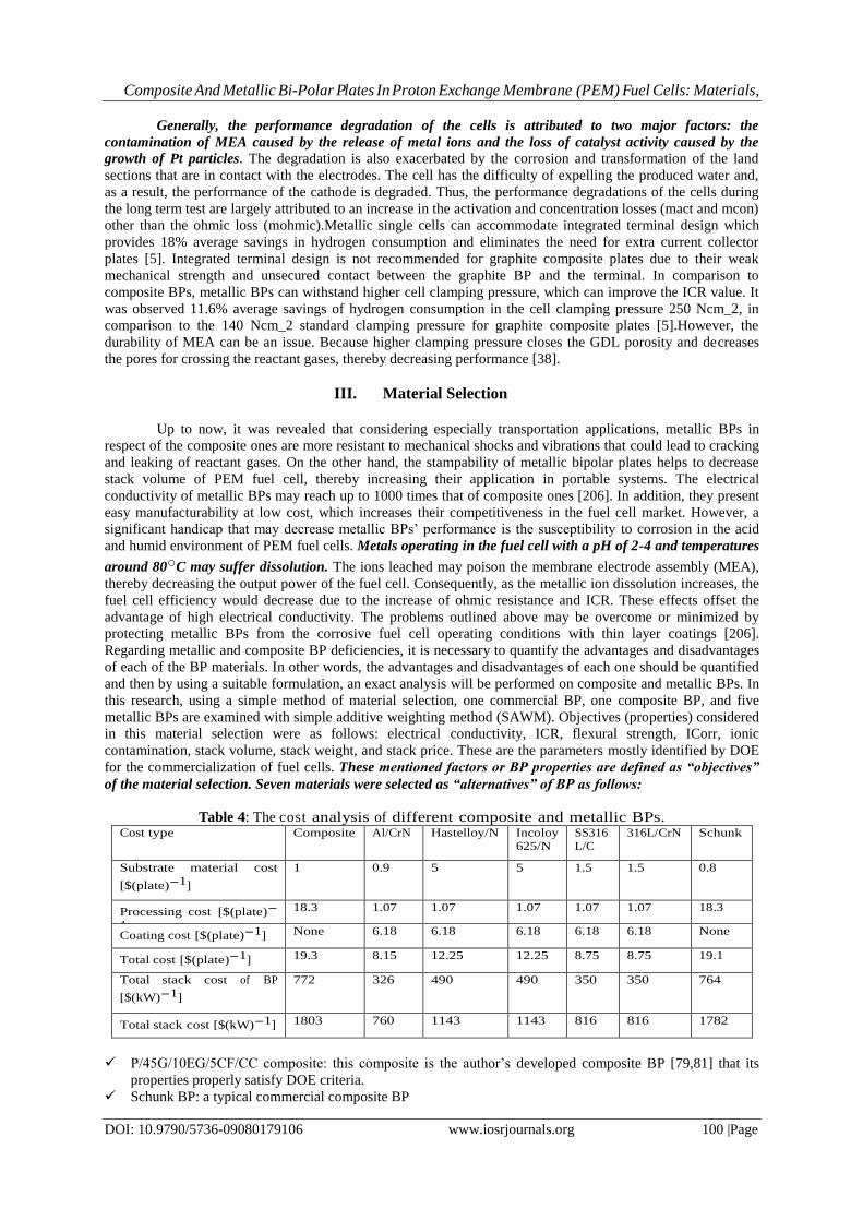
Composite And Metallic Bi-Polar Plates In Proton Exchange Membrane (PEM) Fuel Cells: Materials,
DOI: 10.9790/5736-09080179106 www.iosrjournals.org 100 |Page
Generally, the performance degradation of the cells is attributed to two major factors: the
contamination of MEA caused by the release of metal ions and the loss of catalyst activity caused by the
growth of Pt particles. The degradation is also exacerbated by the corrosion and transformation of the land
sections that are in contact with the electrodes. The cell has the difficulty of expelling the produced water and,
as a result, the performance of the cathode is degraded. Thus, the performance degradations of the cells during
the long term test are largely attributed to an increase in the activation and concentration losses (mact and mcon)
other than the ohmic loss (mohmic).Metallic single cells can accommodate integrated terminal design which
provides 18% average savings in hydrogen consumption and eliminates the need for extra current collector
plates [5]. Integrated terminal design is not recommended for graphite composite plates due to their weak
mechanical strength and unsecured contact between the graphite BP and the terminal. In comparison to
composite BPs, metallic BPs can withstand higher cell clamping pressure, which can improve the ICR value. It
was observed 11.6% average savings of hydrogen consumption in the cell clamping pressure 250 Ncm_2, in
comparison to the 140 Ncm_2 standard clamping pressure for graphite composite plates [5].However, the
durability of MEA can be an issue. Because higher clamping pressure closes the GDL porosity and decreases
the pores for crossing the reactant gases, thereby decreasing performance [38].
III. Material Selection
Up to now, it was revealed that considering especially transportation applications, metallic BPs in
respect of the composite ones are more resistant to mechanical shocks and vibrations that could lead to cracking
and leaking of reactant gases. On the other hand, the stampability of metallic bipolar plates helps to decrease
stack volume of PEM fuel cell, thereby increasing their application in portable systems. The electrical
conductivity of metallic BPs may reach up to 1000 times that of composite ones [206]. In addition, they present
easy manufacturability at low cost, which increases their competitiveness in the fuel cell market. However, a
significant handicap that may decrease metallic BPs’ performance is the susceptibility to corrosion in the acid
and humid environment of PEM fuel cells. Metals operating in the fuel cell with a pH of 2-4 and temperatures
around 80○C may suffer dissolution. The ions leached may poison the membrane electrode assembly (MEA),
thereby decreasing the output power of the fuel cell. Consequently, as the metallic ion dissolution increases, the
fuel cell efficiency would decrease due to the increase of ohmic resistance and ICR. These effects offset the
advantage of high electrical conductivity. The problems outlined above may be overcome or minimized by
protecting metallic BPs from the corrosive fuel cell operating conditions with thin layer coatings [206].
Regarding metallic and composite BP deficiencies, it is necessary to quantify the advantages and disadvantages
of each of the BP materials. In other words, the advantages and disadvantages of each one should be quantified
and then by using a suitable formulation, an exact analysis will be performed on composite and metallic BPs. In
this research, using a simple method of material selection, one commercial BP, one composite BP, and five
metallic BPs are examined with simple additive weighting method (SAWM). Objectives (properties) considered
in this material selection were as follows: electrical conductivity, ICR, flexural strength, ICorr, ionic
contamination, stack volume, stack weight, and stack price. These are the parameters mostly identified by DOE
for the commercialization of fuel cells. These mentioned factors or BP properties are defined as “objectives”
of the material selection. Seven materials were selected as “alternatives” of BP as follows:
Table 4: The cost analysis of different composite and metallic BPs. Cost type Composite Al/CrN Hastelloy/N Incoloy
625/N
SS316
L/C
316L/CrN Schunk
Substrate material cost
[$(plate)-1]
1 0.9 5 5 1.5 1.5 0.8
Processing cost [$(plate)-
1]
18.3 1.07 1.07 1.07 1.07 1.07 18.3
Coating cost [$(plate)-1] None 6.18 6.18 6.18 6.18 6.18 None
Total cost [$(plate)-1] 19.3 8.15 12.25 12.25 8.75 8.75 19.1
Total stack cost of BP
[$(kW)-1]
772 326 490 490 350 350 764
Total stack cost [$(kW)-1] 1803 760 1143 1143 816 816 1782
P/45G/10EG/5CF/CC composite: this composite is the author’s developed composite BP [79,81] that its
properties properly satisfy DOE criteria.
Schunk BP: a typical commercial composite BP
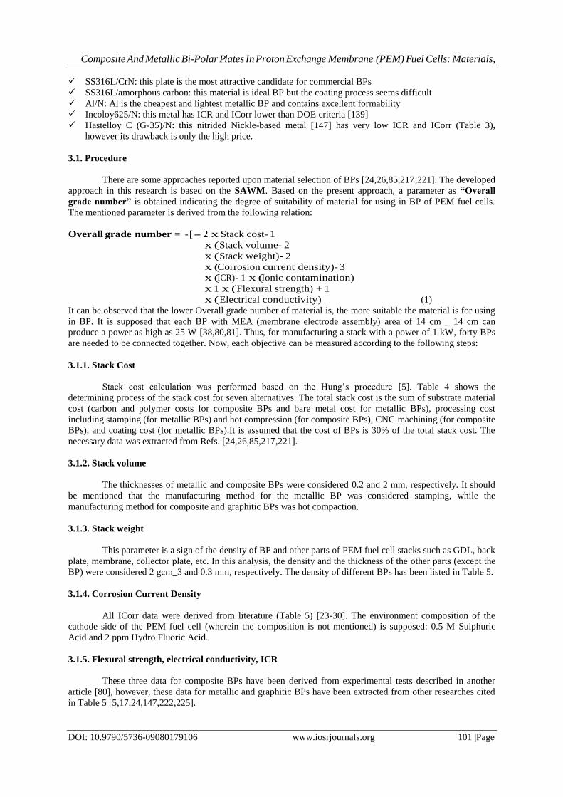
Composite And Metallic Bi-Polar Plates In Proton Exchange Membrane (PEM) Fuel Cells: Materials,
DOI: 10.9790/5736-09080179106 www.iosrjournals.org 101 |Page
SS316L/CrN: this plate is the most attractive candidate for commercial BPs
SS316L/amorphous carbon: this material is ideal BP but the coating process seems difficult
Al/N: Al is the cheapest and lightest metallic BP and contains excellent formability
Incoloy625/N: this metal has ICR and ICorr lower than DOE criteria [139]
Hastelloy C (G-35)/N: this nitrided Nickle-based metal [147] has very low ICR and ICorr (Table 3),
however its drawback is only the high price.
3.1. Procedure
There are some approaches reported upon material selection of BPs [24,26,85,217,221]. The developed
approach in this research is based on the SAWM. Based on the present approach, a parameter as “Overall
grade number” is obtained indicating the degree of suitability of material for using in BP of PEM fuel cells.
The mentioned parameter is derived from the following relation:
Overall grade number = -[- 2 x Stack cost- 1
x ( Stack volume- 2
x ( Stack weight)- 2
x (Corrosion current density)- 3
x (ICR)- 1 x (Ionic contamination)
x 1 x ( Flexural strength) + 1
x ( Electrical conductivity) (1)
It can be observed that the lower Overall grade number of material is, the more suitable the material is for using
in BP. It is supposed that each BP with MEA (membrane electrode assembly) area of 14 cm _ 14 cm can
produce a power as high as 25 W [38,80,81]. Thus, for manufacturing a stack with a power of 1 kW, forty BPs
are needed to be connected together. Now, each objective can be measured according to the following steps:
3.1.1. Stack Cost
Stack cost calculation was performed based on the Hung’s procedure [5]. Table 4 shows the
determining process of the stack cost for seven alternatives. The total stack cost is the sum of substrate material
cost (carbon and polymer costs for composite BPs and bare metal cost for metallic BPs), processing cost
including stamping (for metallic BPs) and hot compression (for composite BPs), CNC machining (for composite
BPs), and coating cost (for metallic BPs).It is assumed that the cost of BPs is 30% of the total stack cost. The
necessary data was extracted from Refs. [24,26,85,217,221].
3.1.2. Stack volume
The thicknesses of metallic and composite BPs were considered 0.2 and 2 mm, respectively. It should
be mentioned that the manufacturing method for the metallic BP was considered stamping, while the
manufacturing method for composite and graphitic BPs was hot compaction.
3.1.3. Stack weight
This parameter is a sign of the density of BP and other parts of PEM fuel cell stacks such as GDL, back
plate, membrane, collector plate, etc. In this analysis, the density and the thickness of the other parts (except the
BP) were considered 2 gcm_3 and 0.3 mm, respectively. The density of different BPs has been listed in Table 5.
3.1.4. Corrosion Current Density
All ICorr data were derived from literature (Table 5) [23-30]. The environment composition of the
cathode side of the PEM fuel cell (wherein the composition is not mentioned) is supposed: 0.5 M Sulphuric
Acid and 2 ppm Hydro Fluoric Acid.
3.1.5. Flexural strength, electrical conductivity, ICR
These three data for composite BPs have been derived from experimental tests described in another
article [80], however, these data for metallic and graphitic BPs have been extracted from other researches cited
in Table 5 [5,17,24,147,222,225].
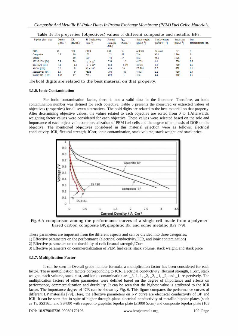
Composite And Metallic Bi-Polar Plates In Proton Exchange Membrane (PEM) Fuel Cells: Materials,
DOI: 10.9790/5736-09080179106 www.iosrjournals.org 102 |Page
Table 5: The properties (objectives) values of different composite and metallic BPs.
The bold digits are related to the best material on that property.
3.1.6. Ionic Contamination
For ionic contamination factor, there is not a valid data in the literature. Therefore, an ionic
contamination number was defined for each objective. Table 5 presents the measured or extracted values of
objectives (properties) for all seven alternatives. The bold digits are related to the best material on that property.
After determining objective values, the values related to each objective are sorted from 0 to 1.Afterwards,
weighting factor values were considered for each objective. These values were selected based on the role and
importance of each objective in commercialization of PEM fuel cells and the degree of emphasis of DOE on the
objective. The mentioned objectives considered in this material selection were as follows: electrical
conductivity, ICR, flexural strength, ICorr, ionic contamination, stack volume, stack weight, and stack price.
Fig. 6.A comparison among the performance curves of a single cell made from a polymer
based carbon composite BP, graphitic BP, and some metallic BPs [79].
These parameters are important from the different aspects and can be divided into three categories:
1) Effective parameters on the performance (electrical conductivity,ICR, and ionic contamination)
2) Effective parameters on the durability of cell: flexural strength,ICorr
3) Effective parameters on commercialization of PEM fuel cells: stack volume, stack weight, and stack price
3.1.7. Multiplication Factor
It can be seen in Overall grade number formula, a multiplication factor has been considered for each
factor. These multiplication factors corresponding to ICR, electrical conductivity, flexural strength, ICorr, stack
weight, stack volume, stack cost, and ionic contamination are _3, 1, 1, _2, _2, _1, _2, and _1, respectively. The
multiplication factors of other parameters were defined based on the degree of importance and effects on
performance, commercialization and durability. It can be seen that the highest value is attributed to the ICR
factor. The importance degree of ICR can be shown by Fig. 6. This figure compares the performance curves of
different BP materials [79]. Here, the effective parameters on I-V curve are electrical conductivity of BP and
ICR. It can be seen that in spite of higher through-plane electrical conductivity of metallic bipolar plates (such
as Ti, SS316L, and SS430) with respect to graphitic bipolar plate (z1000 S/cm) and composite bipolar plate (103

Composite And Metallic Bi-Polar Plates In Proton Exchange Membrane (PEM) Fuel Cells: Materials,
DOI: 10.9790/5736-09080179106 www.iosrjournals.org 103 |Page
S/cm), the performance of graphitic and composite BPs are very higher than metallic BPs. This fact is due to the
high ICR value in the metallic BPs, because of natural oxidative cover on them. Therefore, It should be
attempted to decrease the ICR value by coating a suitable layer on them. In this material selection, I supposed
that ICR of BP is the most important property in comparison to other objectives. Thus, the highest
multiplication factor was attributed to ICR and other multiplication factors were selected based on their effect
on performance, durability, and commercialization of PEM fuel cells. It should be mentioned that the selection
of multiplication factors is implicit and is based on my individual findings from literature.
3.2. Discussion on Material Selection
It should be emphasized that the volume, weight, and cost of stacks are effective factors in
commercialization of PEM fuel cells (Table 5). BPs includes the major part of weight and volume of stacks.
Based on Table 5, the lowest stack weight is related to Al/CrN. The cost order between seven alternatives
introduced in this material selection is as follows: Composite > Schunk > Hastelloy/N > Incoloy625 >
SS316L/CrN > SS316L/C > Al/CrN.It can be seen that the composite BPs contains the cost value much more
than the metallic BPs especially Al/CrN. This finding conflicts with Planes’ finding [37] and agrees with
Hung’s finding [5]. Planes et al. [37] reported that the composite BPs are cheaper than metallic BPs, however
Hung believes that the CNC machining of channels substantially enhances the cost value of composite. Cost is
one major factor that has impeded the introduction of fuel cells as primary energy sources into different sectors
of the economy.
Fig. 7. The overall grade number of the different bipolar plate materials.
Accordingly, identifying opportunities for cost reduction in the material and manufacture of the
different components of PEMFCs, as well as improving their life expectancy, can significantly increase their
chance of becoming a major player in the energy market. Table 5, also indicates that carbon-coated SS316L
exhibits the lowest value of corrosion current density in the acidic environment of PEM fuel cell. Fig.7 .properly
shows the Overall grade number values of different alternatives based on equation no.1. It should be mentioned
that the lower Overall grade number depicts the most suitable material for using as BP. Fig. 7 shows that the
composites have the greatest value of Overall grade number. This indicates that the composites are suitable only
for use in laboratory application not as commercial BPs. The Overall grade numbers in metallic BPs are as this
order:
SS316L/C < Hastelloy (G-30)/N < Al/CrN < Incoloy625 < DOE < SS316/CrN.
As above order, the least of Overall grade number is related to SS316L/C containing the properties
beyond the DOE criteria. The Overall grade number of SS316/CrN is much more than SS316/C. The large
difference is as a result of the difference between ICR and ICorr.The carbon coating is much more conductive
than CrN-coating. Moreover, ICorr of SS316/C (0.06 mAcm_2) is lower than that of SS316/CrN (1.3 mAcm_2).
It can also be observed that after SS316L/C,the N-coated Hastelloy(G-30) is the best candidate for BP. The
Selected materials in this material selection are in close agreement with the commercial materials utilized in
industry for bipolar plates. Based on literature [147,224], the most favourite materials for commercial BPs are
coated SS316L and coated Hastelloy C.
Composite And Metallic Bi-Polar Plates In Proton Exchange Membrane (PEM) Fuel Cells: Materials,
DOI: 10.9790/5736-09080179106 www.iosrjournals.org 104 |Page
IV. Conclusions
Because of its high efficiency, low-temperature operation, high power density, and relatively fast start
up, the proton exchange membrane fuel cell offers the potential for a near-zero emission power source for
transportation, mobile, and stationary applications. However, for such power sources to become main stream
and gain a sizable share of the market, they must be able to compete with other power sources in the terms of
size, weight, cost, performance, and durability. Bipolar plates are one of the critical device of PEM fuel cells
contain the major part of weight, volume, and cost of fuel cell stacks. This research was an attempt to
investigate the state-of-the-art materials currently used for bipolar plate of PEM fuel cell. In the literature, the
metallic and polymer-based composite bipolar plates have replaced the graphite ones. Therefore, in this article a
comprehensive investigation upon the properties and performance of metallic and composite bipolar plates was
introduced. In respect of composite bipolar plates, the common polymer and filler materials as well as their
properties, production methods of composite BPs, ICR values between composite BP and GDL, and the
mechanical as well as electrical properties of composites were completely evaluated. In the case of metallic
bipolar plates, the substrate materials, properties (especially in respect of ICR and corrosion resistivity),
coatings, coating methods, challenges of stamping process, and ionic contaminations were inclusively
investigated. The literature review showed that the metallic BPs, in comparison to composite BPs, offer higher
strength and electrical conductivity, better formability and manufacturability, lower gas permeability, and better
shock resistance. Furthermore, their unique mechanical properties allow the fabrication of thinner plates,
thereby reducing the stack weight, volume, and cost. However, they are, more susceptible to corrosion, which
can adversely influence their performance and durability.
The ionic contamination is another concern resulted from the corrosion of metallic bipolar plates. This
problem has necessitated the need for the application of corrosion resistant coatings to eliminate or reduce the
corrosion rate. Most researches have been focused on the iron based alloys, such as stainless steels, because of
their low costs; however, more recently, considerable efforts have been expended to use the Ni-based alloys as
the material of choice for fabricating bipolar plates. Coatings such as nitridation, CrN, and amorphous carbon
are the most well-liked coatings for ferrous alloys. Nevertheless, to precisely assess the performance of plated
metallic bipolar plates in the stack, more researches would be required upon long time tests. The polymer-
based carbon composite BPs in spite of lower electrical conductivity, non-stampability, and weaker mechanical
properties in comparison to the metallic BPs, contain higher corrosion resistivity, higher durability, lower
density, and lower ionic contamination. Material selection results on seven common bipolar plate materials
indicated that the least values of stack cost, volume, weight, ICR, contamination, and ICorr were related to
carbon-coated SS316L. However, after that Hastelloy (G-30)/N was the next candidate material to be utilized in
BPs.
Acknowledgements
The author Raja Vadivelan.M, India is very much grateful in acknowledging Titan Company Limited -
Jewellery & Watch Divisions, Hosur,Tamilnadu,India ; Karpagam University,Karpagam Acadamy of Higher
Education,Coimbatore,Tamilnadu,India ; Arignar Anna Government Arts College-Cheyyar,Tiruvannamalai
District,Tamilnadu,India ; Sri Ranganathar Institute of Engineering and Technology,Coimbatore,India ; V.O.C
College, Tutricorin,Tamilnadu,India ; Central Electro Chemical Research Institute (CECRI),
Karaikudi,Tamilandu,India for their significant helps and support from individuals of these great
organizations/institutions in completing the author’s planned research work & execution to accomplish his Ph.D
course...
References [1]. J. Marcinkoski, J.P. Kopasz, T.G. Benjamin, Int. J. Hydrogen Energy 33 (14) (2008) 3894-3902. [2]. T. Fukutsuka, et al., J. Power Sources 174 (1) (2007) 199-205.
[3]. K. Feng, et al., Int. J. Hydrogen Energy 35 (2) (2010) 690-700.
[4]. M. Miller, A. Bazylak, J. Power Sources 196 (2) (2011) 601-613. [5]. Y. Hung, Performance evaluation and characterization of metallic bipolar plates in a Proton Exchange Membrane (PEM) fuel cell,
in: Materials Science and Engineering 2010, Stony Brook University.
[6]. R.F. Silva, et al., Electrochim. Acta 51 (17) (2006) 3592-3598. [7]. M. Li, et al., Corros. Sci. 46 (6) (2004) 1369-1380.
[8]. M. Kumagai, et al., Electrochim. Acta 53 (12) (2008) 4205-4212.
[9]. B.K. Kakati, D. Deka, Electrochim. Acta 52 (25) (2007) 7330-7336. [10]. L. Du, S.C. Jana, J. Power Sources 172 (2) (2007) 734-741.
[11]. W. Vielstich, H.A. Gasteiger, A. Lamm, Handbook of Fuel Cells-fundamentals, Technology and Applications, vol. 3, Wiley &
Sons, New York, 2003. [12]. J.G. Clulow, et al., Fuel cell technology: opportunities and challenges topical, in: AIChE Spring National Meeting, 2002, pp. 417-
425. New Orleans.

Composite And Metallic Bi-Polar Plates In Proton Exchange Membrane (PEM) Fuel Cells: Materials,
DOI: 10.9790/5736-09080179106 www.iosrjournals.org 105 |Page
[13]. S.J. Lee, et al., J. Power Sources 131 (1e2) (2004) 162-168.
[14]. H. Wang, J.A. Turner, J. Power Sources 128 (2) (2004) 193-200.
[15]. S. Joseph, et al., Int. J. Hydrogen Energy 30 (12) (2005) 1339-1344. [16]. V.V. Nikam, R.G. Reddy, Int. J. Hydrogen Energy 31 (13) (2006) 1863-1873.
[17]. K. Feng, et al., Int. J. Hydrogen Energy 34 (16) (2009) 6771e6777.
[18]. H. Wang, G. Teeter, J. Turner, J. Electrochem. Soc. 152 (3) (2005) B99-B104. [19]. L. Bozec, et al., Corros. Sci. 43 (4) (2001) 765e786.
[20]. D. Hamm, C.O.A. Olsson, D. Landolt, Corros. Sci. 44 (5) (2002) 1009-1025.
[21]. L.G. Xia, et al., J. Power Sources 178 (1) (2008) 363-367. [22]. G. Tibbetts, et al., Compos. Sci. Technol. 67 (7e8) (2007) 1709-1718.
[23]. V. Mehta, J.S. Cooper, J. Power Sources 114 (1) (2003) 32-53.
[24]. S. Karimi, et al., Adv. Mater. Sci. Eng. 1155 (2012) 1-22. [25]. R. Sengupta, et al., Prog. Polym. Sci. 36 (5) (2011) 638-670.
[26]. M.C.L. de Oliveira, G. Ett, R.A. Antunes, J. Power Sources 206 (2012) 3e13.
[27]. S. Chunhui, et al., J. Compos. Mater. 40 (9) (2006) 839-848. [28]. R.G. Sheppard, D.M. Mathes, D.J. Bray, Properties and characteristics of graphite for industrial applications, in: Poco Graphite,
2001, pp. 5e7.
[29]. A. Heinzel, J. Power Sources 131 (1e2) (2004) 35-40. [30]. H. Kuan, et al., J. Power Sources 134 (1) (2004) 7-17.
[31]. B.D. Cunningham, J. Huang, D.G. Baird, Int. Mater. Rev. 52 (1) (2007) 1-13.
[32]. M.H. Al-Saleh, U. Sundararaj, Compos. Part A: Appl. Sci. Manuf. 42 (12)(2011) 2126e2142. [33]. [33] H. Wang, J.A. Turner, Fuel Cells 10 (4) (2010) 510e519.
[34]. [34] A. Hermann, T. Chaudhuri, P. Spagnol, Int. J. Hydrogen Energy 30 (12) (2005)
[35]. 1297e1302. [36]. L. Flandin, et al., J. Appl. Polym. Sci. 76 (6) (2000) 894-905.
[37]. S.R. Dhakate, et al., Int. J. Hydrogen Energy 33 (23) (2008) 7146-7152.
[38]. E. Planes, L. Flandin, N. Alberola, Energy Proc. 20 (2012) 311-323. [39]. R. Taherian, Manufacture, test, modeling of polymer-based nanocompositeutilized in bipolar plate of PEM fuel cell, in: Material
Engineering, ShirazUniversity, 2012, p. 246.
[40]. H. Chen, et al., Int. J. Hydrogen Energy 35 (7) (2010) 3105-3109. [41]. H. Lee, et al., J. Mater. Process. Technol. 187-188 (2007) 425-428.
[42]. S.I. Heo, et al., J. Power Sources 171 (2) (2007) 396-403.
[43]. R. Mathur, et al., J. Mater. Process. Technol. 203 (1e3) (2008) 184-192.
[44]. T.M. Besmann, et al., J. Electrochem. Soc. 147 (11) (2000) 4083-4086.
[45]. B.K. Kakati, D. Sathiyamoorthy, A. Verma, Int. J. Hydrogen Energy 35 (9) (2010) 4185e4194.
[46]. S. Dhakate, et al., Int. J. Hydrogen Energy 32 (17) (2007) 4537-4543. [47]. C. Yen, et al., J. Power Sources 162 (1) (2006) 309-315.
[48]. M.A. Raza, et al., Nucleus 46 (3) (2009).
[49]. S.H. Liao, et al., J. Power Sources 195 (23) (2010) 7808-7817. [50]. B.K. Kakati, D. Deka, Energy Fuels 21 (3) (2007) 1681-1687.
[51]. S. Liao, et al., J. Power Sources 185 (2) (2008) 1225-1232.
[52]. J.H. Lee, et al., J. Power Sources 193 (2) (2009) 523-529. [53]. D. Ratna, Handbook of Thermoset Resins, iSmithers, 2009.
[54]. Y. Wang, Conductive thermoplastic composite blends for flow field plates for use in polymer electrolyte membrane fuel cells
(PEMFC), in: Chemical Engineering, 2006. Waterloo. [55]. F. Mighri, M.A. Huneault, M.F. Champagne, Polym. Eng. Sci. 44 (9) (2004) 1755e1765.
[56]. Y. Rungsima, et al., Macromol. Symp. 264 (1) (2008) 34e43.
[57]. C. Handleya, N.P. Brandonb, R.V.D. Vorst, J. Power Sources 106 (2002) 344-352. [58]. R. Dweiri, J. Sahari, J. Power Sources 171 (2) (2007) 424-432.
[59]. X.Z. Yuan, et al., J. New Mater. Electrochem. Syst. 8 (2005) 257-267.
[60]. S. Chunhui, Int. J. Hydrogen Energy 33 (3) (2008) 1035-1039. [61]. C.D. Rio, et al., J. Appl. Polym. Sci. 83 (13) (2002) 2817-2822.
[62]. T. Arai, et al., J. Polym. Sci. Part B: Polym. Phys. 43 (18) (2005) 2568-2577. [63]. M. Wu, J. Power Sources 136 (1) (2004) 37e44.
[64]. B. Cunningham, J. Huang, D. Baird, J. Power Sources 165 (2) (2007) 764-773.
[65]. S.C. Chen, et al., J. Appl. Polym. Sci. 98 (3) (2005) 1072-1080. [66]. E. Cho, J. Power Sources 125 (2) (2004) 178e182.
[67]. B. Cunningham, D.G. Baird, J. Mater. Chem. 16 (2006) 4385-4388.
[68]. B. Cunningham, D. Baird, J. Power Sources 168 (2) (2007) 418-425. [69]. T. Yang, P. Shi, J. Power Sources 175 (1) (2008) 390-396.
[70]. C. Marais, P. Feillard, Compos. Sci. Technol. 45 (1992) 247-255.
[71]. A. Wang, et al., Tribol. Int. 31 (11) (1998) 661e667. [72]. R.A. Hauser, Synergistic effects and modeling of thermally conductive resins for fuel cell bipolar plate applications, in: Chemical
Engineering, Michigan Technological University, Michigan, 2008.
[73]. J. Kuo, C. Chen, J. Power Sources 162 (1) (2006) 207-214. [74]. H. Wolf, M. Willertporada, J. Power Sources 153 (1) (2006) 41-46.
[75]. J.M. Taylor, Thermoplastic composites for polymer electrolyte membrane fuel cell bipolar plates, in: Chemical Engineering, 2006.
Waterloo. [76]. M. Meyyappan, in: B. Raton (Ed.), Carbon Nanotubes Science and Applications, CRC Press, London, 2005.
[77]. M.A. Abanilla, Y. Li, V.M. Karbhari, Compos. Part B: Eng. 37 (2e3) (2005 200e212.
[78]. R. Taherian, A. Nozad, M.J. Hadianfard, Mater. Des. 32 (7) (2011) 3883-3892. [79]. R. Taherian, et al., The effect of ohmic resistances and clamping pressure on the performance of proton exchange membrane fuel
cell, in: 7th International Chemical Engineering Congress and Exhibition, 2011. Kish, Iran.
[80]. R. Taherian, M.J. Hadianfard, A. Nozad, ECS J. Solid State Sci. Technol. 1 (6) (2012) 1e8.

Composite And Metallic Bi-Polar Plates In Proton Exchange Membrane (PEM) Fuel Cells: Materials,
DOI: 10.9790/5736-09080179106 www.iosrjournals.org 106 |Page
[81]. R. Taherian, M.J. Hadianfard, A. Nozad, Mater. Des. 49 (2013) 242-251.
[82]. R. Taherian, M.J. Hadinfard, A. Nozad, Manufacture polymer based nanocomposite bipolar plate of PEM fuel cell, in: I.r. office
(Ed.), Invention establish office of Iran, Shiraz University, Iran, 2012. [83]. D.P. Wilkinson, et al., Proton Exchange Membrane Fuel Cells: Materials Properties and Performance, CRC Press, 2010.
[84]. B. Cunningham, The development of compression moldable polymer composite bipolar plates for fuel cells, in: Macromolecular
Science and Engineering, 2007. Blacksburg: Virginia. [85]. J.K. Kuo, S. Mi Chang, Compound Material for Injection Molded PEM Fuel Cell Bipolar Plates, ICSET, 2008.
[86]. H. Tawfik, Y. Hung, D. Mahajan, J. Power Sources 163 (2) (2007) 755-767.
[87]. R. Taherian, et al., Int. J. Eng. Res. Afr. 5 (2011) 16e29. [88]. S.A.R. Hashmi, U.K. Dwivedi, N. Chand, Wear 262 (2007) 1426-1432.
[89]. S.S. Dihrab, et al., Renew. Sustain. Energy Rev. 13 (2009) 1663e1668.
[90]. S.K. Kamarudin, et al., J. Power Sources 157 (2006) 641. [91]. J. Larminie, A. Dicks, Fuel Cell Systems Explained, John Wiley, USA, 2001.
[92]. R.C. Makkus, et al., Fuel Cells Bull. 17 (2000) 5e9.
[93]. A. Celzard, et al., J. Phys. D. Appl. Phys. 33 (2000) 3094e3101. [94]. M. Chen, X.J.W. Shen, W.Y. Huang, J. Mater. Sci. Lett. 21 (3) (2002) 213e214.
[95]. H. Chen, et al., J. Appl. Polym. Sci. 82 (10) (2001) 2506e2513.
[96]. L.N. Song, et al., Mater. Chem. Phys. 93 (1) (2005) 122e128. [97]. H. Chen, et al., Adv. Mater. 20 (18) (2008) 3557e3561.
[98]. X. Yan, et al., J. Power Sources 160 (1) (2006) 252e257.
[99]. W. Zheng, S.C. Wong, Compos. Sci. Technol. 63 (2) (2003) 225e235. [100]. J.K. Park, et al., Compos. Sci. Technol. 68 (7e8) (2008) 1734e1741.
[101]. G. Zheng, et al., Carbon 42 (14) (2004) 2839e2847.
[102]. Y. Zhao, et al., Compos. Sci. Technol. 67 (11e12) (2007) 2528e2534. [103]. D. Li, et al., J. Power Sources 183 (2) (2008) 571e575.
[104]. W. Chen, Y. Liu, Q. Xin, Int. J. Hydrogen Energy 35 (8) (2010) 3783e3788.
[105]. L. Song, M. Xiao, Y. Meng, Compos. Sci. Technol. 66 (13) (2006) 2156e2162. [106]. A. Yasmin, J. Luo, I. Daniel, Compos. Sci. Technol. 66 (9) (2006) 1182e1189.
[107]. A.R. Antunes, et al., J. Power Sources 196 (6) (2011) 2945e2961.
[108]. C. Xiang, et al., Mater. Lett. 64 (11) (2010) 1313e1315. [109]. M. Krzesi_nska, et al., Mater. Chem. Phys. 97 (1) (2006) 173e181.
[110]. C. Du, et al., J. Power Sources 195 (2010) 5312e5319.
[111]. R. Taherian, M.J. Hadianfard, A. Nazad, J. Appl. Polym. Sci. 128 (3) (2013) 1497e1509.
[112]. N. Murdie, Carbon Fiber/Carbon composites: production, properties, and applications, in: Introduction to Carbon Technologies,
Secretariado do Publicaciones, Spain: University of Alicante, 1997.
[113]. O.P. Bahl, et al., in: J.B. Donnet, et al. (Eds.), Manufacture of Carbon Fibers, 1998. New York, NY. [114]. H.P. Maheshwari, R.B. Mathur, T.L. Dhami, J. Power Sources 173 (1) (2007) 394e403.
[115]. T. Yang, S. Pengfei, J. Power Sources 175 (1) (2008) 390e396.
[116]. J.W. Kim, et al., J. Power Sources 195 (17) (2010) 5474e5480. [117]. G. Zhang, et al., Carbon 46 (2) (2008) 196e205.
[118]. R. Taipalus, et al., Compos. Sci. Technol. 61 (6) (2001) 801e814.
[119]. J.B. Donnet, et al., Gummi Kunstst 49 (4) (1996) 274e279. [120]. P.C. Ma, et al., Compos. Part A: Appl. Sci. Manuf. 41 (10) (2010) 1345e1367.
[121]. A. Zettl, Chapter 1 Nanotubes: An Experimental Overview, Carbon Nanotubes: Quantum Cylinders of Graphene, 2008.
[122]. S.R. Dhakate, et al., Int. J. Hydrogen Energy 35 (9) (2010) 4195e4200. [123]. M.C. Hsiao, et al., J. Power Sources 195 (17) (2010) 5645e5650.
[124]. M.C.L. de Oliveira, G. Ett, R.A. Antunes, J. Power Sources 221 (2013) 345e355.
[125]. T. Kuilla, et al., Prog. Polym. Sci. 35 (2010) 1350e1375. [126]. R.D. Dreyer, et al., Chem. Soc. Rev. 39 (2010) 228e240.
[127]. G. Wang, et al., J. Phys. Chem. Part C 112 (2008) 8192e8195.
[128]. G. Wang, et al., Carbon 47 (2009) 1359e1364. [129]. X. Li, et al., Science 319 (2008) 1229e1231.
[130]. P. Blake, et al., Nano Lett. 8 (2008) 1704e1708. [131]. B.K. Kakati, A.G. Ghosh, A. Verma, Int. J. Hydrogen Energy 38 (2013) 9362e 9369.
[132]. P.J. Hamilton, B.G. Pollet, Fuel Cells 10 (4) (2010) 489e509.
[133]. S. Radhakrishnan, et al., J. Power Sources 163 (2007) 702e707. [134]. Q. Yin, et al., J. Power Sources 165 (2) (2007) 717e721.
[135]. Q. Yin, et al., J. Power Sources 175 (2) (2008) 861-865.
[136]. T. Kinumoto, et al., J. Power Sources 195 (19) (2010) 6473-6477. [137]. J. André, L. Antoni, J.P. Petit, Int. J. Hydrogen Energy 35 (8) (2010) 3684- 3697.
[138]. Y. Hung, H. Tawfik, D. Mahajan, J. Power Sources 186 (1) (2009) 123-127.
[139]. R.A. Antunes, et al., Int. J. Hydrogen Energy 35 (8) (2010) 3632-3647. [140]. A.V. Nikiforov, et al., Int. J. Hydrogen Energy 36 (1) (2011) 111-119.
[141]. J.A. Turner, H. Wang, M.P. Brady, Corrosion protection of metallic bipolar plates for fuel cells, in: DOE Hydrogen Program
Review, National Renewable Energy Laboratory, USA, 2005. [142]. Y. Yang, L.J. Guo, H. Liu, Int. J. Hydrogen Energy 36 (2) (2011) 1654-1663.
[143]. K. Feng, et al., Diam. Relat. Mater. 19 (11) (2010) 1354e1361.
[144]. C.Y. Chung, et al., J. Power Sources 176 (1) (2008) 276-281. [145]. H. Marsh, A.P. Warburton, J. Appl. Chem. 20 (4) (1970) 133-142.
[146]. B. Wu, et al., Int. J. Hydrogen Energy 35 (24) (2010) 13255-13261.
[147]. H. Wang, et al., J. Power Sources 138 (2004) 79-85. [148]. M.P. Brady, et al., Int. J. Hydrogen Energy 32 (16) (2007) 3778-3788.
[149]. Y.C. Park, et al., Int. J. Hydrogen Energy (2013).
[150]. B. Yang, et al., J. Power Sources 174 (1) (2007) 228-236.

Composite And Metallic Bi-Polar Plates In Proton Exchange Membrane (PEM) Fuel Cells: Materials,
DOI: 10.9790/5736-09080179106 www.iosrjournals.org 107 |Page
[151]. Z.L. Zhang, T. Bell, Surf. Eng. 1 (1985) 131-136.
[152]. S.H. Lee, et al., Int. J. Hydrogen Energy 35 (2) (2010) 725-730.
[153]. M.P. Brady, et al., JOM 58 (2006) 50-57. [154]. M.P. Brady, et al., Scr. Mater. 50 (2004) 1017-1022.
[155]. H.Y. Lee, et al., Int. J. Hydrogen Energy 33 (2008) 4171-4177.
[156]. Z.L. Zhang, T. Bell, J. Surf. Eng. 1 (1985) 131-136. [157]. W. Hong, et al., Int. J. Hydrogen Energy 36 (3) (2011) 2207-2212.
[158]. R. Tian, J. Sun, L. Wang, Int. J. Hydrogen Energy 31 (13) (2006) 1874-1878.
[159]. R. Tian, J. Sun, L. Wang, J. Power Sources 163 (2) (2007) 719-724. [160]. L. Yang, et al., J. Power Sources 195 (9) (2010) 2810-2814.
[161]. C.Y. Bai, et al., Int. J. Hydrogen Energy 36 (6) (2011) 3975-3983.
[162]. C.Y. Bai, et al., J. Power Sources 195 (3) (2010) 779-786. [163]. N.D. Nam, et al., Thin Solid Films (2011).
[164]. D. Zhang, et al., Int. J. Hydrogen Energy 35 (8) (2010) 3721-3726.
[165]. W. Yoon, et al., J. Power Sources 179 (1) (2008) 265-273. [166]. A.S.f. Metals, Metals Handbook: Surface Cleaning, Finishing, and Coating, 10 ed., vol. 5, ASM Handbook, 1994. USA.
[167]. J.Y. Lin, et al., Surf. Coat Technol. 205 (7) (2010) 2251-2255.
[168]. A.E. Fetohi, et al., Int. J. Hydrogen Energy 37 (9) (2012) 7677-7688. [169]. K. Feng, et al., Mater. Chem. Phys. 126 (1e2) (2011) -11.
[170]. K. Feng, et al., Surf. Coat. Technol. 205 (1) (2010) 85-91.
[171]. O. Lavigne, et al., Surf. Coat Technol. 205 (7) (2010) 1870-1877. [172]. A.K. Mishra, R. Balasubramaniam, Corros. Sci. 49 (3) (2007) 1027-1044.
[173]. C.M. Abreu, et al., Electrochim. Acta 47 (13e14) (2002) 2215-2222.
[174]. J. Barranco, et al., Int. J. Hydrogen Energy 35 (20) (2010) 11489-11498. [175]. C.H. Lee, et al., Renew. Energy 54 (2013) 46-50.
[176]. J.R. Mawdsley, et al., J. Power Sources 231 (2013) 106-112.
[177]. S. Mahabunphachai, O.N. Cora, M. Koç, J. Power Sources 195 (16) (2010) 5269-5277. [178]. Z. Huabing, et al., Int. J. Hydrogen Energy 36 (9) (2011) 5695-5701.
[179]. K. Feng, et al., J. Power Sources 195 (19) (2010) 6798-6804.
[180]. L.F. Peng, et al., Mater. Des. 30 (2009) 783-790. [181]. M.C. Li, et al., J. Fuel Cell Sci. Technol. 5 (2008) 0110141-0110146.
[182]. L.F. Peng, et al., J. Fuel Cell Sci. Technol. 7 (2010) 0310091-0310099.
[183]. J. Marcinkoski, et al., J. Power Sources 196 (2011) 5282-5292.
[184]. D. Qiu, et al., Int. J. Hydrogen Energy 38 (2013) 6762-6772.
[185]. L. Peng, et al., J. Fuel Cell Sci. Technol. 8 (2011) 1-8.
[186]. F. Dundar, et al., J. Power Sources 195 (2010) 3546-3552. [187]. W.K. Lee, et al., J. Power Sources 84 (1999) 45-51.
[188]. G. Liu, Z.Q. Lin, Y.X. Bao, Finite Elem. Anal. Des. 39 (2002) 107-118.
[189]. D.A. Liu, L.F. Peng, X.M. Lai, Int. J. Hydrogen Energy 34 (2009) 990-997. [190]. D. Deng, H. Murakawa, Comput. Mater. Sci. 43 (2008) 591-607.
[191]. S. Mahabunphachai, O.N. Cora, M. Koc, J. Power Sources 195 (2010) 5269-5277.
[192]. M.F. Peker, O.N. Cora, M. Koc, Int. J. Hydrogen Energy 36 (2011) 15427-15436. [193]. B. Avasarala, P. Haldar, J. Power Sources 188 (2009) 225e229.
[194]. D.A. Liu, L.F. Peng, X.M. Lai, Int. J. Hydrogen Energy 34 (2) (2009) 990-997.
[195]. F. Dundar, et al., J. Power Sources 195 (11) (2010) 3546e3552. [196]. E. Dur, O.N. Cora, M. Koç, J. Power Sources 196 (3) (2011) 1235e1241.
[197]. Y.H. Yun, Int. J. Hydrogen Energy 35 (4) (2010) 1713e1718.
[198]. M.P. Brady, et al., Nitrided Metallic Bipolar Foils in PEM Fuel Cells, Oak Ridge National Laboratory: U.S. Department of Energy. [199]. C. Turan, Ö.N. Cora, M. Koç, J. Power Sources 243 (2013) 925-934.
[200]. X. Cheng, et al., J. Power Sources 165 (2) (2007) 739e756.
[201]. A. Pozio, et al., Electrochim. Acta 48 (2003) 1543e1549. [202]. M.P. Brady, et al., Scr. Mater. 50 (7) (2004) 1017e1022.
[203]. N. Zamel, X. Li, Prog. Energy Combust. Sci. 37 (3) (2011) 292e329. [204]. M. Sulek, et al., J. Power Sources 196 (2011) 8967e8972.
[205]. Y.C. ParK, et al., Int. J. Hydrogen Energy 35 (9) (2010) 4320e4328.
[206]. B. Cunningham, The development of compression moldable polymer composite bipolar plates for fuel cells, in: Faculty of Virginia Polytechnic Institute and State University, 2007, pp. 22e39. Virginia.
[207]. A. Collier, et al., Int. J. Hydrogen Energy 31 (13) (2006) 1838e1854.
[208]. M.J. Kelly, et al., Solid State Ionics 176 (2005) 2111e2114. [209]. M.J. Kelly, et al., J. Power Sources 145 (2005) 249e252.
[210]. T. Okada, Effect of ionic contaminants, in: W. Vielstich, H.A. Gasteiger, Lamm (Eds.), Handbook of Fuel Cells Fundamentals,
Technology and Applications,vol. 3, John Wiley and Sons, Ltd., 2003, p. 627. [211]. M. Shi, F.C. Anson, J. Electroanal. Chem. 425 (1997) 117e123.
[212]. M.P. Brady, et al., Int. J. Hydrogen Energy 38 (2013) 4734e4739.
[213]. M.P. Brady, et al., Cost-Effective Surface Modification For Metallic Bipolar Plates, Oak ridge National Laboratory, 2005. [214]. C. Mele, B. Bozzini, J. Power Sources 195 (11) (2010) 3590e3596.
[215]. M.P. Brady, et al., J. Power Sources 195 (17) (2010) 5610e5618.
[216]. T.J. Toops, et al., J. Power Sources 195 (17) (2010) 5619e5627. [217]. P. Chatterjee, V.M. Athawale, S. Chakraborty, Mater. Des. 32 (2) (2011) 851e 860.
[218]. I. Bar-On, R. Kirchain, R. Roth, J. Power Sources 109 (2002) 71e75.
[219]. K. Jayakumar, et al., J. Power Sources 161 (1) (2006) 454e459. [220]. A. Jahan, et al., Mater. Des. 31 (2) (2010) 696e705.
[221]. A. Shanian, O. Savadogo, J. Power Sources 159 (2006) 1095e1104.
[222]. S. Radhakrishnan, Developments in conducting polymer composites and coatings for bipolar plates, in: Reports for NCL, 2012.

Composite And Metallic Bi-Polar Plates In Proton Exchange Membrane (PEM) Fuel Cells: Materials,
DOI: 10.9790/5736-09080179106 www.iosrjournals.org 108 |Page
[223]. J. Barranco, et al., J. Power Sources 196 (9) (2011) 4283e4289.
[224]. A. Pozio, et al., J. Power Sources 179 (2) (2008) 631e639.
[225]. L. Ma, S. Warthesen, D.A. Shores, J. New Mater. Electrochem. Syst. 3 (2000) 221e228. [226]. L. Bing, et al., Int. J. Hydrogen Energy 35 (7) (2010) 2643e2647.
[227]. Z. Bin, et al., J. Power Sources 161 (2) (2006) 997e1001.
[228]. M. Wu, L. Shaw, Int. J. Hydrogen Energy 30 (4) (2005) 373e380. [229]. K. Shigehiro, U. Hiroyuki, W. Masahiro, Electrochim. Acta 53 (4) (2007) 2025e2033.
[230]. S. Dhakate, et al., Int. J. Hydrogen Energy 33 (23) (2008) 7146e7152.
[231]. R. Yeetsorn, et al., Macromol. Symp. 264 (1) (2008) 34e43. [232]. J. Zhang, Y.W. Zou, J. He, J. Zhejiang Univ. Sci. 6A (10) (2005) 1080e1083.
[233]. D.P. Davies, et al., J. Appl. Electrochem. 30 (1) (2000) 101e105.
[234]. J. Jayaraj, et al., Mater. Sci. Eng. A 449e451 (2007) 30e33. [235]. F. Yu, et al., Int. J. Hydrogen Energy 34 (2009) 453e458.
[236]. R. Tian, J. Power Sources 196 (3) (2011) 1258e1263.
[237]. B.C. Cha, et al., Int. J. Hydrogen Energy 36 (7) (2011) 4565e4572. [238]. D. Zhang, et al., Int. J. Hydrogen Energy 36 (3) (2011) 2184e2189.
[239]. M. Zhang, et al., J. Power Sources 196 (6) (2011) 3249e3254.
[240]. H. Han, et al., Int. J. Hydrogen Energy 34 (5) (2009) 2387e2395. [241]. W.G. Lee, et al., J. Alloys Compd. 474 (1e2) (2009) 268e272.
[242]. Y. Fu, et al., Int. J. Hydrogen Energy 34 (1) (2009) 405e409.
[243]. S.T. Myung, Electrochem. Commun. 10 (2008) 480e484. [244]. H. Wang, et al., J. Power Sources 178 (1) (2008) 238-247.
[245]. P. Ju, et al., Corros. Sci. 66 (2013) 330-336.
[246]. C.Y. Bai, M.D. Ger, M.S. Wu, Int. J. Hydrogen Energy 34 (16) (2009) 6778-6789.