complete catalog 2009
TRANSCRIPT

Cab l e Tray S ys t emsE n g i n e e r e d t o S u p p o r t P o w e r f u l R e p u t a t i o n s
Page 1
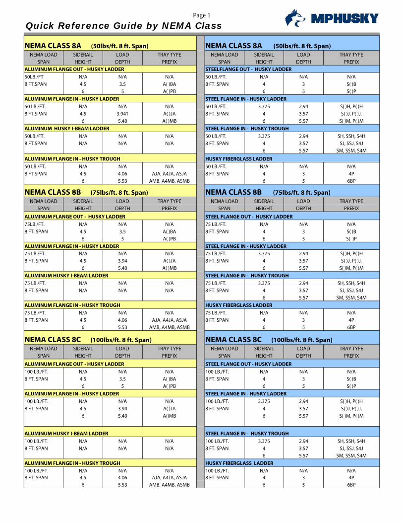
Quick Reference Guide by NEMA Class NEMA CLASS 8A (50lbs/ft. 8 ft. Span) NEMA CLASS 8A (50lbs/ft. 8 ft. Span)
NEMA LOAD SIDERAIL LOAD TRAY TYPE NEMA LOAD SIDERAIL LOAD TRAY TYPE SPAN HEIGHT DEPTH PREFIX SPAN HEIGHT DEPTH PREFIX
ALUMINUM FLANGE OUT - HUSKY LADDER STEELFLANGE OUT - HUSKY LADDER 50LB./FT N/A N/A N/A 50 LB./FT. N/A N/A N/A 8 FT.SPAN 4.5 3.5 A( )BA 8 FT. SPAN 4 3 S( )B 6 5 A( )PB 6 5 S( )P ALUMINUM FLANGE IN - HUSKY LADDER STEEL FLANGE IN - HUSKY LADDER 50 LB./FT. N/A N/A N/A 50 LB./FT. 3.375 2.94 S( )H, P( )H 8 FT.SPAN 4.5 3.941 A( )JA 8 FT. SPAN 4 3.57 S( )J, P( )J, 6 5.40 A( )MB 6 5.57 S( )M, P( )M ALUMINUM HUSKY I-BEAM LADDER STEEL FLANGE IN - HUSKY TROUGH 50LB./FT. N/A N/A N/A 50 LB./FT. 3.375 2.94 SH, SSH, S4H 8 FT.SPAN N/A N/A N/A 8 FT. SPAN 4 3.57 SJ, SSJ, S4J 6 5.57 SM, SSM, S4M
ALUMINUM FLANGE IN - HUSKY TROUGH HUSKY FIBERGLASS LADDER 50 LB./FT. N/A N/A N/A 50 LB./FT. N/A N/A N/A 8 FT.SPAN 4.5 4.06 AJA, A4JA, ASJA 8 FT. SPAN 4 3 4P 6 5.53 AMB, A4MB, ASMB 6 5 6BP
NEMA CLASS 8B (75lbs/ft. 8 ft. Span) NEMA CLASS 8B (75lbs/ft. 8 ft. Span) NEMA LOAD SIDERAIL LOAD TRAY TYPE NEMA LOAD SIDERAIL LOAD TRAY TYPE
SPAN HEIGHT DEPTH PREFIX SPAN HEIGHT DEPTH PREFIX
ALUMINUM FLANGE OUT - HUSKY LADDER STEEL FLANGE OUT - HUSKY LADDER 75LB./FT. N/A N/A N/A 75 LB./FT. N/A N/A N/A 8 FT. SPAN 4.5 3.5 A( )BA 8 FT. SPAN 4 3 S( )B 6 5 A( )PB 6 5 S( )P ALUMINUM FLANGE IN - HUSKY LADDER STEEL FLANGE IN - HUSKY LADDER 75 LB./FT. N/A N/A N/A 75 LB./FT. 3.375 2.94 S( )H, P( )H 8 FT. SPAN 4.5 3.94 A( )JA 8 FT. SPAN 4 3.57 S( )J, P( )J, 6 5.40 A( )MB 6 5.57 S( )M, P( )M ALUMINUM HUSKY I-BEAM LADDER STEEL FLANGE IN - HUSKY TROUGH 75 LB./FT. N/A N/A N/A 75 LB./FT. 3.375 2.94 SH, SSH, S4H 8 FT. SPAN N/A N/A N/A 8 FT. SPAN 4 3.57 SJ, SSJ, S4J 6 5.57 SM, SSM, S4M ALUMINUM FLANGE IN - HUSKY TROUGH HUSKY FIBERGLASS LADDER 75 LB./FT. N/A N/A N/A 75 LB./FT. N/A N/A N/A 8 FT. SPAN 4.5 4.06 AJA, A4JA, ASJA 8 FT. SPAN 4 3 4P 6 5.53 AMB, A4MB, ASMB 6 5 6BP
NEMA CLASS 8C (100lbs/ft. 8 ft. Span) NEMA CLASS 8C (100lbs/ft. 8 ft. Span) NEMA LOAD SIDERAIL LOAD TRAY TYPE NEMA LOAD SIDERAIL LOAD TRAY TYPE
SPAN HEIGHT DEPTH PREFIX SPAN HEIGHT DEPTH PREFIX
ALUMINUM FLANGE OUT - HUSKY LADDER STEEL FLANGE OUT - HUSKY LADDER 100 LB./FT. N/A N/A N/A 100 LB./FT. N/A N/A N/A 8 FT. SPAN 4.5 3.5 A( )BA 8 FT. SPAN 4 3 S( )B 6 5 A( )PB 6 5 S( )P ALUMINUM FLANGE IN - HUSKY LADDER STEEL FLANGE IN - HUSKY LADDER 100 LB./FT. N/A N/A N/A 100 LB./FT. 3.375 2.94 S( )H, P( )H 8 FT. SPAN 4.5 3.94 A( )JA 8 FT. SPAN 4 3.57 S( )J, P( )J, 6 5.40 A()MB 6 5.57 S( )M, P( )M
ALUMINUM HUSKY I-BEAM LADDER STEEL FLANGE IN - HUSKY TROUGH 100 LB./FT. N/A N/A N/A 100 LB./FT. 3.375 2.94 SH, SSH, S4H 8 FT. SPAN N/A N/A N/A 8 FT. SPAN 4 3.57 SJ, SSJ, S4J 6 5.57 SM, SSM, S4M ALUMINUM FLANGE IN - HUSKY TROUGH HUSKY FIBERGLASS LADDER 100 LB./FT. N/A N/A N/A 100 LB./FT. N/A N/A N/A 8 FT. SPAN 4.5 4.06 AJA, A4JA, ASJA 8 FT. SPAN 4 3 4P 6 5.53 AMB, A4MB, ASMB 6 5 6BP
Page 2
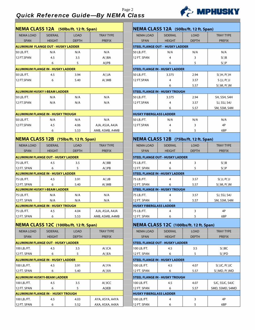
Quick Reference Guide—By NEMA Class NEMA CLASS 12A (50lbs/ft. 12 ft. Span) NEMA CLASS 12A (50lbs/ft. 12 ft. Span)
NEMA LOAD SIDERAIL LOAD TRAY TYPE NEMA LOAD SIDERAIL LOAD TRAY TYPE
SPAN HEIGHT DEPTH PREFIX SPAN HEIGHT DEPTH PREFIX
ALUMINUM FLANGE OUT - HUSKY LADDER STEEL FLANGE OUT - HUSKY LADDER
50 LB./FT. N/A N/A N/A 50 LB./FT. N/A N/A N/A
12 FT.SPAN 4.5 3.5 A( )BA 12 FT. SPAN 4 3 S( )B
6 5 A()PB 6 5 S( )P
ALUMINUM FLANGE IN - HUSKY LADDER STEEL FLANGE IN - HUSKY LADDER
50 LB./FT. 4.5 3.94 A( )JA 50 LB./FT. 3.375 2.94 S( )H, P( )H
12 FT.SPAN 6 5.40 A( )MB 12 FT.SPAN 4 3.57 S ()J, P( )J
6 5.57 S( )M, P( )M
ALUMINUM HUSKY I-BEAM LADDER STEEL FLANGE IN - HUSKY TROUGH
50 LB./FT. N/A N/A N/A 50 LB./FT. 3.375 2.94 SH, SSH, S4H
12 FT.SPAN N/A N/A N/A 12 FT.SPAN 4 3.57 SJ, SSJ, S4J
6 5.57 SM, SSM, S4M
ALUMINUM FLANGE IN - HUSKY TROUGH HUSKY FIBERGLASS LADDER
50 LB./FT. N/A N/A N/A 50 LB./FT. N/A N/A N/A
12 FT.SPAN 4.5 4.06 AJA, ASJA, A4JA 12 FT.SPAN 4 3 4P
6 5.53 AMB, ASMB, A4MB 6 5 6BP
NEMA CLASS 12B (75lbs/ft. 12 ft. Span) NEMA CLASS 12B (75lbs/ft. 12 ft. Span) NEMA LOAD SIDERAIL LOAD TRAY TYPE NEMA LOAD SIDERAIL LOAD TRAY TYPE
SPAN HEIGHT DEPTH PREFIX SPAN HEIGHT DEPTH PREFIX
ALUMINUM FLANGE OUT - HUSKY LADDER STEEL FLANGE OUT - HUSKY LADDER
75 LB./FT. 4.5 3.5 A( )BB 75 LB./FT. 4 3 S( )B
12 FT. SPAN 6 5 A( )PB 12 FT. SPAN 6 5 S( )P
ALUMINUM FLANGE IN - HUSKY LADDER STEEL FLANGE IN –HUSKY LADDER
75 LB./FT. 4.5 3.91 A( )JB 75 LB./FT. 4 3.57 S( )J, P( )J
12 FT. SPAN 6 5.40 A( )MB 12 FT. SPAN 6 5.57 S( )M, P( )M
ALUMINUM HUSKY I-BEAM LADDER STEEL FLANGE IN - HUSKY TROUGH
75 LB./FT. N/A N/A N/A 75 LB./FT. 4 3.57 SJ, SSJ, S4J
12 FT. SPAN N/A N/A N/A 12 FT. SPAN 6 5.57 SM, SSM, S4M
ALUMINUM FLANGE IN - HUSKY TROUGH HUSKY FIBERGLASS LADDER
75 LB./FT. 4.5 4.04 AJA, ASJA, A4JA 75 LB./FT. 4 3 4P
12 FT. SPAN 6 5.53 AMB, ASMB, A4MB 12 FT. SPAN 6 5 6BP
NEMA CLASS 12C (100lbs/ft. 12 ft. Span) NEMA CLASS 12C (100lbs/ft. 12 ft. Span) NEMA LOAD SIDERAIL LOAD TRAY TYPE NEMA LOAD SIDERAIL LOAD TRAY TYPE
SPAN HEIGHT DEPTH PREFIX SPAN HEIGHT DEPTH PREFIX
ALUMINUM FLANGE OUT - HUSKY LADDER STEEL FLANGE OUT - HUSKY LADDER
100 LB./FT. 4.5 3.5 A( )CA 100 LB./FT. 4.5 3.5 S( )BC
12 FT. SPAN 6 5 A( )EA 12 FT. SPAN 6 5 S( )PD
ALUMINUM FLANGE IN - HUSKY LADDER STEEL FLANGE IN - HUSKY LADDER
100 LB./FT. 4.5 3.91 A( )YA 100 LB./FT. 4.5 4.07 S( )JC, P( )JC
12 FT. SPAN 6 5.40 A( )XA 12 FT. SPAN 6 5.57 S( )MD, P( )MD
ALUMINUM HUSKYI-BEAM LADDER STEEL FLANGE IN - HUSKY TROUGH
100 LB./FT. 4.5 3.5 A( )ICC 100 LB./FT. 4.5 4.07 SJC, SSJC, S4JC
12 FT. SPAN 6 5 A()IEB 12 FT. SPAN 6 5.57 SMD, SSMD, S4MD
ALUMINUM FLANGE IN - HUSKY TROUGH HUSKY FIBERGLASS LADDER
100 LB./FT. 4.5 4.03 AYA, ASYA, A4YA 100 LB./FT. 4 3 4P
12 FT. SPAN 6 5.52 AXA, ASXA, A4XA 12 FT. SPAN 6 5 6BP

Page 3
Quick Reference Guide—By NEMA Class NEMA CLASS 16A (50lbs/ft. 16ft. Span) NEMA CLASS 16A (50lbs/ft. 16ft. Span)
NEMA LOAD SIDERAIL LOAD TRAY TYPE NEMA LOAD SIDERAIL LOAD TRAY TYPE SPAN HEIGHT DEPTH PREFIX SPAN HEIGHT DEPTH PREFIX
ALUMINUM FLANGE OUT - HUSKY LADDER STEEL FLANGE OUT - HUSKY LADDER 50 LB./FT. 4.5 3.5 A( )CA 50 LB./FT. 4.5 3.5 S( )CD 16 FT. SPAN 6 5 A( )EA 16 FT. SPAN 6.25 5.25 S( )EB
ALUMINUM FLANGE IN - HUSKY LADDER STEEL FLANGE IN - HUSKY LADDER 50 LB./FT. 4.5 3.91 A( )YA 50 LB./FT. 4.5 3.94 S( )YD, P( )YD 16 FT. SPAN 6 5.40 A( )XA 16 FT. SPAN 6.25 5.69 S( )XB, P( ),XB
ALUMINUM HUSKY I-BEAM LADDER STEEL FLANGE IN - HUSKY TROUGH 50 LB./FT. 4.5 3.5 A( )IYC 50 LB./FT. 4.5 4.07 SYD, SSYD, S4YD 16 FT. SPAN 6 5 A( )IXB 16 FT. SPAN 6.25 5.82 SXB, SSCB, S4XB ALUMINUM FLANGE IN - HUSKY TROUGH HUSKY FIBERGLASS LADDER 50 LB./FT. 4.5 4.03 AYA, ASYA, A4YA 50 LB./FT. 4 3 4P 16 FT. SPAN 6 5.52 AXA, ASXA, A4XA 16 FT. SPAN 6 5 6BP
NEMA CLASS 16B (75lbs/ft. 16ft. Span) NEMA CLASS 16B (75lbs/ft. 16ft. Span) NEMA LOAD SIDERAIL LOAD TRAY TYPE NEMA LOAD SIDERAIL LOAD TRAY TYPE
SPAN HEIGHT DEPTH PREFIX SPAN HEIGHT DEPTH PREFIX
ALUMINUM FLANGE OUT - HUSKY LADDER STEEL FLANGE OUT - HUSKY LADDER 75 LB./FT. 4.5 3.5 A( )CA 75 LB./FT. 4.5 3.5 S( )CD 16 FT. SPAN 6 5 A( )EA 16 FT. SPAN 6.25 5.25 S( )EB
ALUMINUM FLANGE IN - HUSKY LADDER STEEL FLANGE IN - HUSKY LADDER 75 LB./FT. 4.5 3.91 A( )YA 75 LB./FT. 4.5 3.94 S( )YD, P( )YD 16 FT. SPAN 6 5.40 A( )XA 16 FT. SPAN 6.25 5.69 S( )XB, P( )XB ALUMINUM HUSKY I-BEAM LADDER STEEL FLANGE IN - HUSKY TROUGH 75 LB./FT. 4.5 3.5 A( )IYC 75 LB./FT. 4.5 4.07 SYD, SSYD, S4YD 16 FT. SPAN 6 5 A( )IXB 16 FT. SPAN 6.25 5.82 SXB, SSXB, S4XB ALUMINUM FLANGE IN - HUSKY TROUGH HUSKY FIBERGLASS LADDER 75 LB./FT. 4.5 4.03 AYA, ASYA, A4YA 75 LB./FT. N/A N/A N/A 16 FT. SPAN 6 5.52 AXA, ASXA, A4XA 16 FT. SPAN 6 5 6BP
NEMA CLASS 16C (100lbs/ft. 16ft. Span) NEMA CLASS 16C (100lbs/ft. 16ft. Span) NEMA LOAD SIDERAIL LOAD TRAY TYPE NEMA LOAD SIDERAIL LOAD TRAY TYPE
SPAN HEIGHT DEPTH PREFIX SPAN HEIGHT DEPTH PREFIX
ALUMINUM FLANGE OUT - HUSKY LADDER STEEL FLANGE OUT - HUSKY LADDER 100 LB./FT. 4 3 N/A 100 LB./FT. N/A N/A N/A 16 FT. SPAN 6 5 A( )EA 16 FT. SPAN 6.25 5.25 S()EB
ALUMINUM FLANGE IN - HUSKY LADDER STEEL FLANGE IN - HUSKY LADDER 100 LB./FT. 4 3.875 N/A 100 LB./FT. 4 3.5 N/A 16 FT. SPAN 6 5.38 A( )X 16 FT. SPAN 6.25 5.69 S()XB, P( )XB ALUMINUM HUSKY I-BEAM LADDER STEEL FLANGE IN - HUSKY TROUGH 100 LB./FT. 4.5 3.5 A( )IYC 100 LB./FT. 4 3.625 N/A 16 FT. SPAN 6 5 A( )IXB 16 FT. SPAN 6.25 5.82 SXB, SSXB, S4XB ALUMINUM FLANGE IN - HUSKY TROUGH HUSKY FIBERGLASS LADDER 100 LB./FT. 4 3.625 N/A 100 LB./FT. N/A N/A N/A 16 FT. SPAN 6 5.50 AX, ASX, A4X 16 FT. SPAN 6 5 6BP
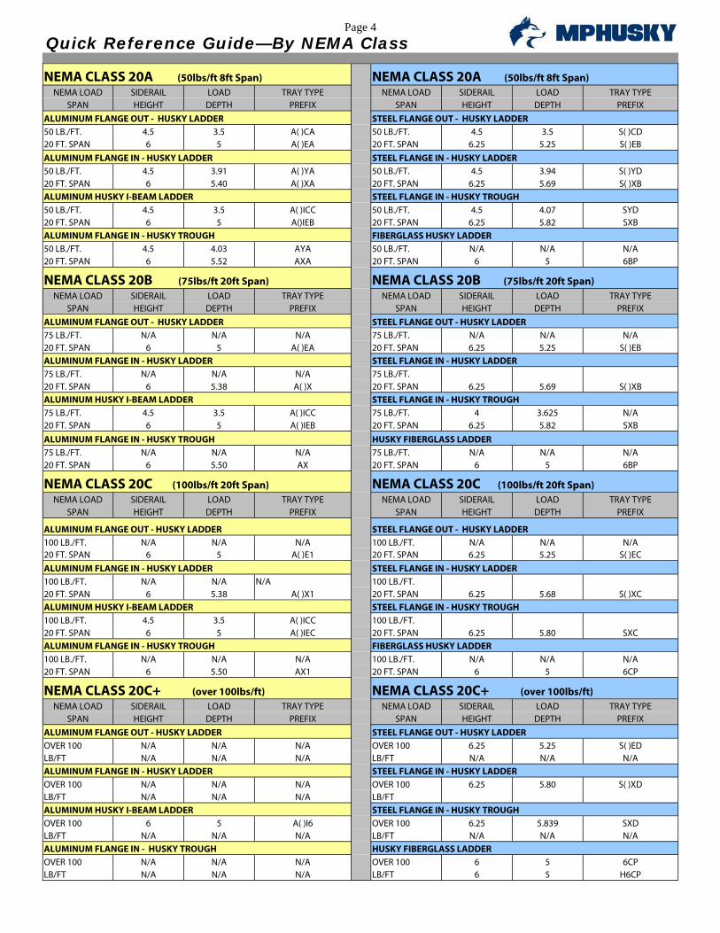
Page 4
Quick Reference Guide—By NEMA Class NEMA CLASS 20A (50lbs/ft 8ft Span) NEMA CLASS 20A (50lbs/ft 8ft Span)
NEMA LOAD SIDERAIL LOAD TRAY TYPE NEMA LOAD SIDERAIL LOAD TRAY TYPE SPAN HEIGHT DEPTH PREFIX SPAN HEIGHT DEPTH PREFIX
ALUMINUM FLANGE OUT - HUSKY LADDER STEEL FLANGE OUT - HUSKY LADDER 50 LB./FT. 4.5 3.5 A( )CA 50 LB./FT. 4.5 3.5 S( )CD 20 FT. SPAN 6 5 A( )EA 20 FT. SPAN 6.25 5.25 S( )EB ALUMINUM FLANGE IN - HUSKY LADDER STEEL FLANGE IN - HUSKY LADDER 50 LB./FT. 4.5 3.91 A( )YA 50 LB./FT. 4.5 3.94 S( )YD 20 FT. SPAN 6 5.40 A( )XA 20 FT. SPAN 6.25 5.69 S( )XB ALUMINUM HUSKY I-BEAM LADDER STEEL FLANGE IN - HUSKY TROUGH 50 LB./FT. 4.5 3.5 A( )ICC 50 LB./FT. 4.5 4.07 SYD 20 FT. SPAN 6 5 A()IEB 20 FT. SPAN 6.25 5.82 SXB ALUMINUM FLANGE IN - HUSKY TROUGH FIBERGLASS HUSKY LADDER 50 LB./FT. 4.5 4.03 AYA 50 LB./FT. N/A N/A N/A 20 FT. SPAN 6 5.52 AXA 20 FT. SPAN 6 5 6BP
NEMA CLASS 20B (75lbs/ft 20ft Span) NEMA CLASS 20B (75lbs/ft 20ft Span) NEMA LOAD SIDERAIL LOAD TRAY TYPE NEMA LOAD SIDERAIL LOAD TRAY TYPE
SPAN HEIGHT DEPTH PREFIX SPAN HEIGHT DEPTH PREFIX ALUMINUM FLANGE OUT - HUSKY LADDER STEEL FLANGE OUT - HUSKY LADDER 75 LB./FT. N/A N/A N/A 75 LB./FT. N/A N/A N/A 20 FT. SPAN 6 5 A( )EA 20 FT. SPAN 6.25 5.25 S( )EB ALUMINUM FLANGE IN - HUSKY LADDER STEEL FLANGE IN - HUSKY LADDER 75 LB./FT. N/A N/A N/A 75 LB./FT. 20 FT. SPAN 6 5.38 A( )X 20 FT. SPAN 6.25 5.69 S( )XB ALUMINUM HUSKY I-BEAM LADDER STEEL FLANGE IN - HUSKY TROUGH 75 LB./FT. 4.5 3.5 A( )ICC 75 LB./FT. 4 3.625 N/A 20 FT. SPAN 6 5 A( )IEB 20 FT. SPAN 6.25 5.82 SXB ALUMINUM FLANGE IN - HUSKY TROUGH HUSKY FIBERGLASS LADDER 75 LB./FT. N/A N/A N/A 75 LB./FT. N/A N/A N/A 20 FT. SPAN 6 5.50 AX 20 FT. SPAN 6 5 6BP
NEMA CLASS 20C (100lbs/ft 20ft Span) NEMA CLASS 20C (100lbs/ft 20ft Span) NEMA LOAD SIDERAIL LOAD TRAY TYPE NEMA LOAD SIDERAIL LOAD TRAY TYPE
SPAN HEIGHT DEPTH PREFIX SPAN HEIGHT DEPTH PREFIX
ALUMINUM FLANGE OUT - HUSKY LADDER STEEL FLANGE OUT - HUSKY LADDER 100 LB./FT. N/A N/A N/A 100 LB./FT. N/A N/A N/A 20 FT. SPAN 6 5 A( )E1 20 FT. SPAN 6.25 5.25 S( )EC ALUMINUM FLANGE IN - HUSKY LADDER STEEL FLANGE IN - HUSKY LADDER 100 LB./FT. N/A N/A N/A 100 LB./FT. 20 FT. SPAN 6 5.38 A( )X1 20 FT. SPAN 6.25 5.68 S( )XC ALUMINUM HUSKY I-BEAM LADDER STEEL FLANGE IN - HUSKY TROUGH 100 LB./FT. 4.5 3.5 A( )ICC 100 LB./FT. 20 FT. SPAN 6 5 A( )IEC 20 FT. SPAN 6.25 5.80 SXC ALUMINUM FLANGE IN - HUSKY TROUGH FIBERGLASS HUSKY LADDER 100 LB./FT. N/A N/A N/A 100 LB./FT. N/A N/A N/A 20 FT. SPAN 6 5.50 AX1 20 FT. SPAN 6 5 6CP
NEMA CLASS 20C+ (over 100lbs/ft) NEMA CLASS 20C+ (over 100lbs/ft) NEMA LOAD SIDERAIL LOAD TRAY TYPE NEMA LOAD SIDERAIL LOAD TRAY TYPE
SPAN HEIGHT DEPTH PREFIX SPAN HEIGHT DEPTH PREFIX ALUMINUM FLANGE OUT - HUSKY LADDER STEEL FLANGE OUT - HUSKY LADDER OVER 100 N/A N/A N/A OVER 100 6.25 5.25 S( )ED LB/FT N/A N/A N/A LB/FT N/A N/A N/A ALUMINUM FLANGE IN - HUSKY LADDER STEEL FLANGE IN - HUSKY LADDER OVER 100 N/A N/A N/A OVER 100 6.25 5.80 S( )XD LB/FT N/A N/A N/A LB/FT ALUMINUM HUSKY I-BEAM LADDER STEEL FLANGE IN - HUSKY TROUGH OVER 100 6 5 A( )I6 OVER 100 6.25 5.839 SXD LB/FT N/A N/A N/A LB/FT N/A N/A N/A ALUMINUM FLANGE IN - HUSKY TROUGH HUSKY FIBERGLASS LADDER OVER 100 N/A N/A N/A OVER 100 6 5 6CP LB/FT N/A N/A N/A LB/FT 6 5 H6CP
MPHusky was founded in 1955 and originally began operations as Husky Products. Over the following 50+ years of leadership and service, MPHusky has gone through several transformations and mergers, including Husky/Burndy and Metal Products, thus leading to what is today MPHusky—America’s leading manufacturer of Cable Tray and Cable bus Power Distribution Systems.
Throughout these changes one thing has remained constant—the “Husky” drive to be the most reliable, highest quality, cost effective and innovative manufacturer of Cable Support Systems and Cable Bus Power Distribution Systems. We have an unsurpassed commitment to customer satisfaction and service, and we are eager to earn your loyalty and trust. As we continue to build and strengthen our partnerships with our customers, we look forward to
the next 50 years of service and support.
Engineered to Support
Powerful Reputations
Aluminum Stainless Steel Wire Mesh Fiberglass Mill Galvanized Zinc Plated Hot Dipped

8 6 4 . 2 3 4 . 4 8 0 0m p h u s k y . c o m
Rev. April 16, 2009 4:01 PMCopyright 2008 MP Husky. All rights reserved.
Cable TRAY Section 1-Technical Data
2
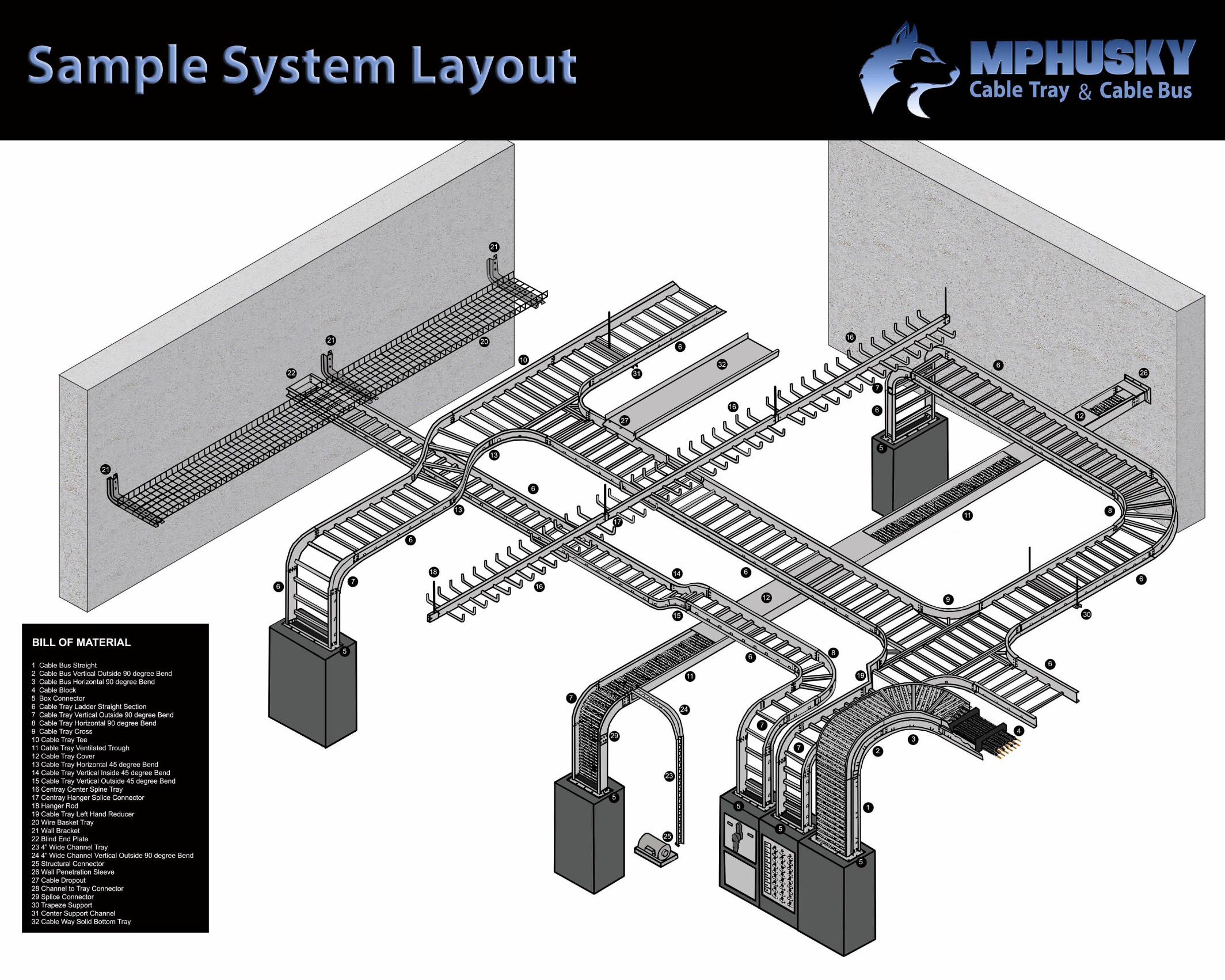
Table of ContentsTechnical Data Section 1 Description and Applications Materials and Construction Corrosion Resistance Loading—Deflection Electrical Design and GroundingHusky Ladder—Flange Out Section 2 Numbering System, Loading Tables, Ordering InformationHusky Ladder—Flange In Section 3 Numbering System, Loading Tables, Ordering InformationHusky I-Beam Ladder Section 4 Numbering System, Loading Tables, Ordering InformationHusky Trough Section 5 Numbering System, Loading Tables, Ordering InformationHusky I-Beam Trough Section 6 Numbering System, Loading Tables, Ordering InformationHusky Track Section 7 Numbering System, Loading Tables, Ordering InformationHusky Channel Section 8 Description and Applications—Horizontal Bends Horizontal Crosses and Tees—Vertical BendsCable Tray Fittings for Ladder and Trough Section 9 Horizontals—Verticals—Crosses—Tees—ReducersAccessories and Splice Connectors Section 10 Hold Down Clips—Expansion Guides—Splice Plates Grounding Connectors—Drill Jigs—AccessoriesSupport Material Section 11 Suspension Channels and Fittings—Clamps Vertical Run Supports—Wall BracketsCovers and Cover Fasteners Section 12 Ordering Information—Cover Fasteners Stand Off Clips—Separators Clamps—Cable Support BlocksHusky Techtray—Wire Mesh Section 13 Numbering System, Loading Tables, Ordering Information Center-Supported Cable Tray—Centray Section 14 Numbering System, Loading Tables, Ordering InformationHusky Fiberglass Section 15 Numbering System, Loading Tables, Ordering InformationStandard Tray Specifications Section 16Request for Quotation FormQuick Reference Guide by NEMA ClassIndexSample System Layout

8 6 4 . 2 3 4 . 4 8 0 0m p h u s k y . c o mRev. April 16, 2009 4:01 PM
Copyright 2008 MP Husky. All rights reserved.
Section 1-Technical Data CABLE TRAY
3
IntroductionMPHusky has been in the Cable Tray business since 1955. Over the past 50+ years of leadership and service, MPHusky has gone through several transformations and mergers, including Husky/Burndy and Metal Products, thus leading to what is today MPHusky—America’s leading manufacturer of Cable Tray and Cable Bus Power Distribution Systems.
Throughout these changes one thing has remained constant—the “Husky” drive to be the most reliable, highest quality, cost effective and innovative manufacturer of Cable Support Systems and Cable Bus Power Distribution Systems. We have an unsurpassed commitment to customer satisfaction and service, and we are eager to earn your loyalty and trust.
Description and Selection
Cable Tray systems provide rigid structural support for cables in a variety of commercial and industrial applications. The basic styles of cable tray are: Ladder, Trough, Center Rail, Wire Basket and Channel. For a more comprehensive description of the construction and utilization of these types of tray, turn to Sections 2, 3, 4, 5, 6, 7, 8,13, 14 and 15 in this catalog.
Husky LadderLadder consists of two longitudinal side members connected by individual traverse members. It is intended for use as a power cable or control cable support.
Husky TroughTrough has a corrugated solid or ventilated bottom, 4” rung spacing or flat bottom pan design which is contained within longitudinal side members. It is especially appropriate for control and instrumentation cables.
Husky ChannelChannel is a one piece support with either ventilated or solid bottom sections. These sections are used with a single power cable, multiple control, or signal circuit cables.

8 6 4 . 2 3 4 . 4 8 0 0m p h u s k y . c o mRev. April 16, 2009 4:01 PM
Copyright 2008 MP Husky. All rights reserved.
Section 1-Technical Data CABLE TRAY
4
Description and SelectionHusky Wire BasketTechtray is a wire mesh cable tray system that utilizes high mechanical strength steel wire that is welded into a 2” x 2” grid system. This grid system is then formed into channels which support and carry cables.
Husky Pan TrayHusky Way is a one piece formed pan that provides a flat bottom and a fill depth that is almost the same as the outside height of the tray. It is the most economical of all the tray systems.
Since Cable Tray is used in a wide variety of applications and under widely varying conditions, it is im-portant that you gain an understanding of material specifications and structural design and apply that knowledge when selecting trays and specifying fittings, parts, and accessories. Some of the considerations are:
NEMA Class / CSA Class1. Using the charts below, determine the correct class of tray as it relates to your desired loading capacity per foot and support span. You will also need to know the weight of the cable and at what span it will be supported.
Material 2. MPHusky cable tray is available in aluminum, stainless steel and hot dip galvanized after fabrication or pre-galvanized steel, galvannealed and fiberglass.
Tray Depth 3. A loading depth from 3” to 7” is available.
Tray Width 4. Standard widths are 6”, 9”, 12”, 18”, 24”, 30” and 36”.
Tray Type 5. Seven types of tray are available: Ladder, Trough, Channel, I-Beam, Center Spline, Fiberglass, and Wire Mesh. Lad-der is available with either 6”, 9”, 12” or 18” rung spacing. Both Channel and Trough are available with either solid, non-ventilated or ventilated bottoms.
Radius of Fittings 6. All fittings normally come with a 12”, 24” or 36” radius in styles and material to match any tray selection.
Technical Information
8 6 4 . 2 3 4 . 4 8 0 0m p h u s k y . c o m
Rev. April 16, 2009 4:01 PMCopyright 2008 MP Husky. All rights reserved.
Cable TRAY Section 1-Technical Data
5
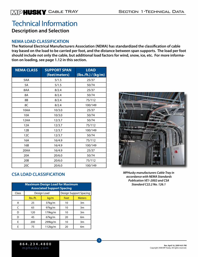
NEMA LOAD CLASSIFICATIONThe National Electrical Manufacturers Association (NEMA) has standardized the classification of cable tray based on the load to be carried per foot, and the distance between span supports. The load per foot should include not only the cable, but additional load factors for wind, snow, ice, etc. For more informa-tion on loading, see page 1.12 in this section.
NEMA CLASS SUPPORT SPAN(feet/meters)
LOAD(lbs./ft.) / (kg/m)
5AA 5/1.5 25/37
5A 5/1.5 50/74
8AA 8/2.4 25/37
8A 8/2.4 50/74
8B 8/2.4 75/112
8C 8/2.4 100/149
10AA 10/3.0 25/37
10A 10/3.0 50/74
12AA 12/3.7 50/74
12A 12/3.7 75/112
12B 12/3.7 100/149
12C 12/3.7 50/74
16A 16/4.9 75/112
16B 16/4.9 100/149
20AA 16/4.9 25/37
20A 20/6.0 50/74
20B 20/6.0 75/112
20C 20/6.0 100/149
CSA LOAD CLASSIFICATION
lbs./ft. kg/m Feet Meters
A 25 37kg/m 10 3m
C 65 97kg/m 10 3m
D 120 179kg/m 10 3m
D 45 67kg/m 20 6m
E 200 299kg/m 10 3m
E 75 112kg/m 20 6m
Technical InformationDescription and Selection
Class Design Load Design Support Spacing
Maximum Design Load for Maximum Associated Support Spacing
MPHusky manufacturers Cable Tray in accordance with NEMA Standards
Publication VE1-2002 and CSA Standard C22.2 No. 126.1
8 6 4 . 2 3 4 . 4 8 0 0m p h u s k y . c o mRev. April 16, 2009 4:01 PM
Copyright 2008 MP Husky. All rights reserved.
Section 1-Technical Data CABLE TRAY
6
Materials & ConstructionCable tray systems are commonly fabricated from a corrosion-resistant metal or from a metal with a corrosion-resistant finish. The selection of the proper material is essentially an economic consideration.
Every cable tray installation places requirements on the mechanical properties of the material from which it is fabricated. These properties influence the spacing frequency of supporting members, and the ease of installation. The selection of the material may also be dependent upon electrical (conductivity), physical (appearance), or chemical (corrosion resistance) properties, according to the demands of the specific installation. Although there are numerous metals available which could satisfy the basic requirements, certain wrought aluminum alloys and low carbon steels meet these requirements most economically.
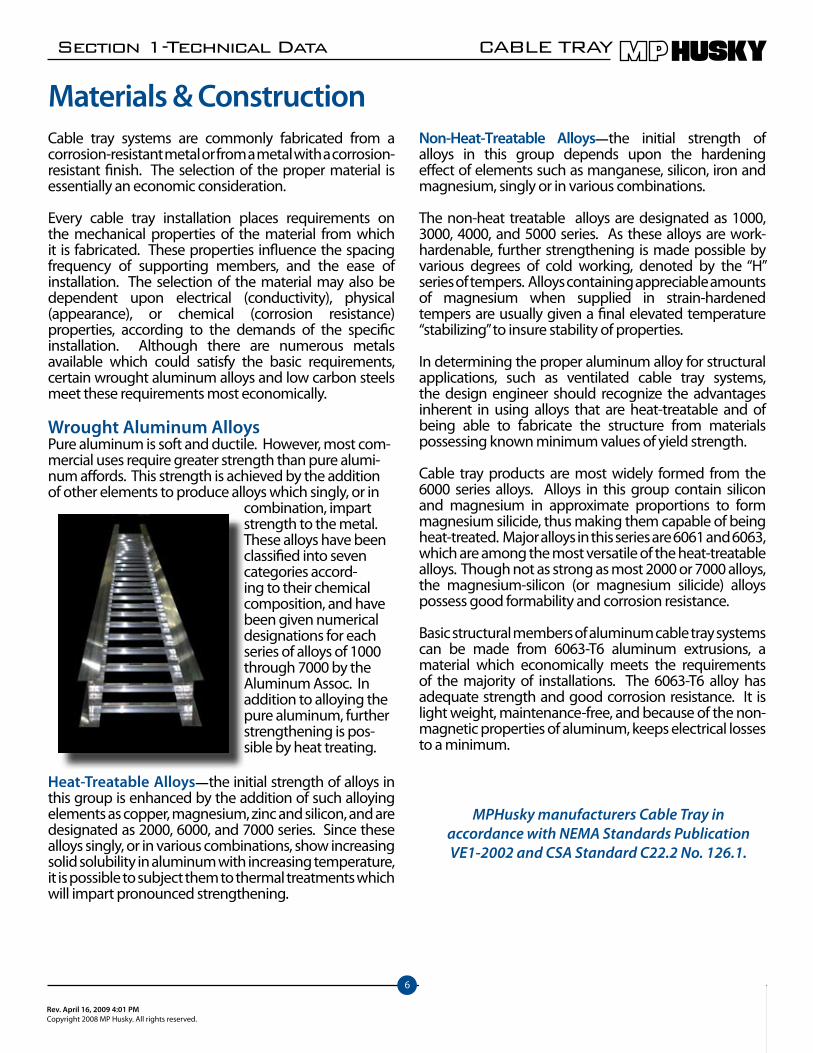
Wrought Aluminum AlloysPure aluminum is soft and ductile. However, most com-mercial uses require greater strength than pure alumi-num affords. This strength is achieved by the addition of other elements to produce alloys which singly, or in
combination, impart strength to the metal. These alloys have been classified into seven categories accord-ing to their chemical composition, and have been given numerical designations for each series of alloys of 1000 through 7000 by the Aluminum Assoc. In addition to alloying the pure aluminum, further strengthening is pos-sible by heat treating.
Heat-Treatable Alloys—the initial strength of alloys in this group is enhanced by the addition of such alloying elements as copper, magnesium, zinc and silicon, and are designated as 2000, 6000, and 7000 series. Since these alloys singly, or in various combinations, show increasing solid solubility in aluminum with increasing temperature, it is possible to subject them to thermal treatments which will impart pronounced strengthening.
Non-Heat-Treatable Alloys—the initial strength of alloys in this group depends upon the hardening effect of elements such as manganese, silicon, iron and magnesium, singly or in various combinations.
The non-heat treatable alloys are designated as 1000, 3000, 4000, and 5000 series. As these alloys are work-hardenable, further strengthening is made possible by various degrees of cold working, denoted by the “H” series of tempers. Alloys containing appreciable amounts of magnesium when supplied in strain-hardened tempers are usually given a final elevated temperature “stabilizing” to insure stability of properties.
In determining the proper aluminum alloy for structural applications, such as ventilated cable tray systems, the design engineer should recognize the advantages inherent in using alloys that are heat-treatable and of being able to fabricate the structure from materials possessing known minimum values of yield strength.
Cable tray products are most widely formed from the 6000 series alloys. Alloys in this group contain silicon and magnesium in approximate proportions to form magnesium silicide, thus making them capable of being heat-treated. Major alloys in this series are 6061 and 6063, which are among the most versatile of the heat-treatable alloys. Though not as strong as most 2000 or 7000 alloys, the magnesium-silicon (or magnesium silicide) alloys possess good formability and corrosion resistance.
Basic structural members of aluminum cable tray systems can be made from 6063-T6 aluminum extrusions, a material which economically meets the requirements of the majority of installations. The 6063-T6 alloy has adequate strength and good corrosion resistance. It is light weight, maintenance-free, and because of the non-magnetic properties of aluminum, keeps electrical losses to a minimum.
MPHusky manufacturers Cable Tray in accordance with NEMA Standards Publication VE1-2002 and CSA Standard C22.2 No. 126.1.

8 6 4 . 2 3 4 . 4 8 0 0m p h u s k y . c o m
Rev. April 16, 2009 4:01 PMCopyright 2008 MP Husky. All rights reserved.
Cable TRAY Section 1-Technical Data
7
Materials & ConstructionSteelSteel cable trays are used principally in environments which are relatively free from corrosive attack. They are available with various types of corrosion-resistant finishes; usually hot-dip galvanized. The main advantages of using steel in cable tray fabrication are its high strength and low cost. Its disadvantages are increased structural weight, poor corrosion-resistance, and low electrical conductivity.
The idea that all steels are the same, except for chemical disposition is false. Carbon steels may be produced with chemical compositions (carbon, manganese, phosphorus, sulphur and silicon) within the specified limits of a given grade and still have characteristics that are widely dissimilar. Each grade and quality variation has a useful place, depending upon the end use and the methods of fabrication.
Basic components of steel cable trays are normally fabricated from either hot or cold rolled steel strips of commercial quality. Steels in this category are ASTM A-1011 CS Type B (formerly ASTMA-569) and ASTM A-1008 CS Type B (formerly A-366). Pre-galvanized steel conforms to ASTM A-653.
Stainless SteelToday, hundreds of different alloy combinations exist for the endless variety of applications which utilize stainless and heat resisting steels. The primary elements added to obtain the various properties required in the steels include chromium, nickel, manganese, silicon, molybdenum, and the stabilizing elements of titanium columbium and tantalum.
Stainless steel contains at least 10 percent chromium, along with other elements to develop specific properties. Depending on the quality of the elements present in a stainless alloy, it will have a metallurgical structure which will be characteristic of the basic stainless steel groups. Metallurgists refer to these groups as the martensitic, ferritic, austenitic and precipitation hardening stainless steels. All standard austenitic alloys are given numbers in the “200” and “300” series, while the martensitic and ferritic alloys are numbered in the “400” series.
If your job calls for stainless steel, please contact the MPHusky factory for assistance in determining the correct type for your
specific application.
MPHusky offers cable trays and accessories in both the 304 and 316 series. These austenitic alloys are remarkable in several respects. Unlike the other two classes, they contain nickel in quantities from 4 to 22 percent, while the percentage of carbon is kept relatively low. When chromium is increased for improved corrosion resistance, nickel must also be increased to retain the austenitic structure.
304 stainless steel has chromium and nickel increased and carbon lowered to reduce carbide precipitation and increase corrosion resistance. Lowering the carbon content also makes welding easier.
316 stainless steel has molybdenum added to improve corrosion resistance and high tempera-ture strength. The carbon content is also lowered to improve welding performance.
8 6 4 . 2 3 4 . 4 8 0 0m p h u s k y . c o mRev. April 16, 2009 4:01 PM
Copyright 2008 MP Husky. All rights reserved.
Section 1-Technical Data CABLE TRAY
8
Materials & ConstructionTypical Applications include:
Type 304 Type 316Beer Barrels Chemical Processing EquipChemical Equipment Chemical Storage and
Transportation tanksCoal Hopper Linings Food Processing EquipCryogenic Vessels and Components
Steam Cooking Kettles
Dairy Equipment Oil Refining EquipmentEvaporators Paper Pulp Digesters and
EvaporatorsFood Handling Equipment Petroleum Refining EquipMilking Machines Pharm. Processing EquipmentNuclear Vessels and Comp Scrubbers and EnvironmentalOil Well Filter Screens Soap and Photographic
Handling EquipmentPressure Vessels General apps in Textile Ind.Sanitary Fittings and ValvesShipping DrumsSteel TubesTextile Dyeing EquipmentHypodermic NeedlesFeedwater Tubing
GalvannealedGalvannealed or Galvanneal, is the result from the com-bined process of galvanizing and annealing the steel. The galvanization is made through the hot-dipping (hot-dip galvanizing) process and gives a very fine grayish matte finish. Galvanneal does not flake off its galvanized coat-ing when formed, stamped, and bent. The very fine matte finish acts like a primer and paint easily adheres to the tray. It is very rust proof, only white to dark grey marks ap-pear if it comes in contact with water. Galvanneal sheets offers good paintability, weldability, corrosion resistance, and formability. It is extensively used in the au-tomotive, signage, electric equipment, and other indus-tries requiring good paintability and long reliable service life.
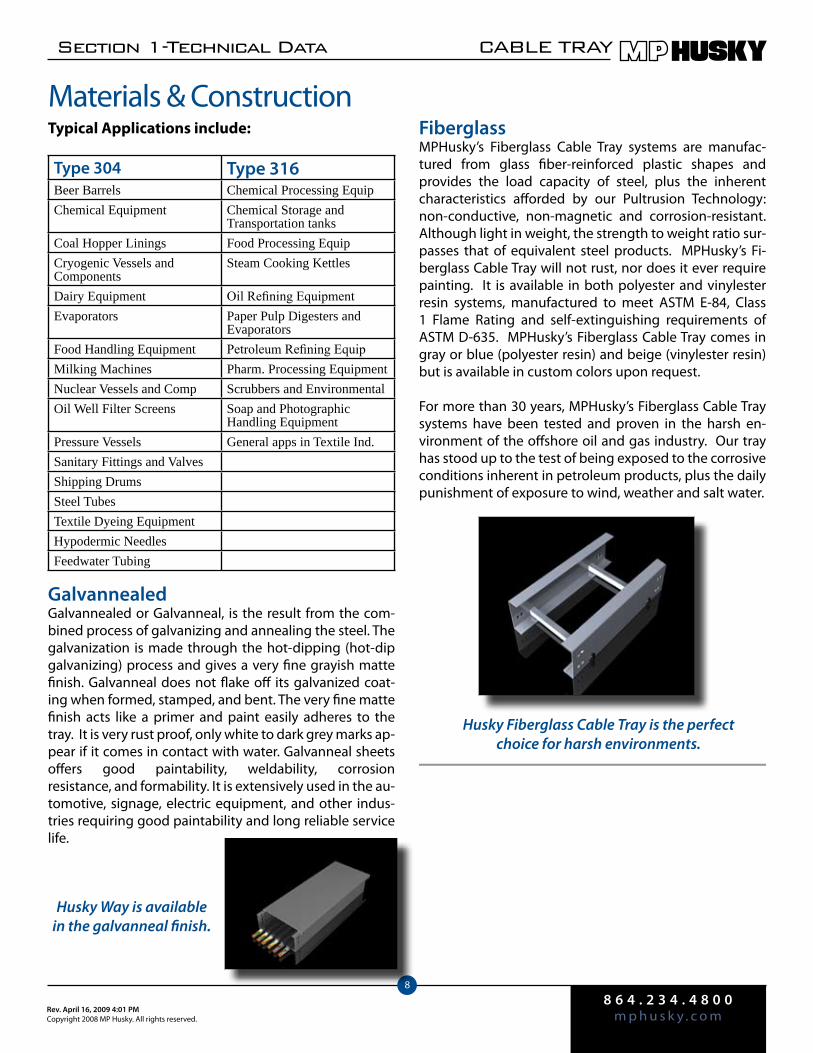
FiberglassMPHusky’s Fiberglass Cable Tray systems are manufac-tured from glass fiber-reinforced plastic shapes and provides the load capacity of steel, plus the inherent characteristics afforded by our Pultrusion Technology: non-conductive, non-magnetic and corrosion-resistant. Although light in weight, the strength to weight ratio sur-passes that of equivalent steel products. MPHusky’s Fi-berglass Cable Tray will not rust, nor does it ever require painting. It is available in both polyester and vinylester resin systems, manufactured to meet ASTM E-84, Class 1 Flame Rating and self-extinguishing requirements of ASTM D-635. MPHusky’s Fiberglass Cable Tray comes in gray or blue (polyester resin) and beige (vinylester resin) but is available in custom colors upon request.
For more than 30 years, MPHusky’s Fiberglass Cable Tray systems have been tested and proven in the harsh en-vironment of the offshore oil and gas industry. Our tray has stood up to the test of being exposed to the corrosive conditions inherent in petroleum products, plus the daily punishment of exposure to wind, weather and salt water.
Husky Fiberglass Cable Tray is the perfect choice for harsh environments.
Husky Way is available in the galvanneal finish.
8 6 4 . 2 3 4 . 4 8 0 0m p h u s k y . c o m
Rev. April 16, 2009 4:01 PMCopyright 2008 MP Husky. All rights reserved.
Cable TRAY Section 1-Technical Data
9
Corrosion ResistanceThe underlying causes of corrosion are the same for all metals, all stemming from electrochemical phenomena. But the ways in which corrosion manifests itself are characteristic of each particular metal. Steel corrodes in the atmosphere with the formation of rust, which devel-ops very rapidly on unprotected surfaces. In a clean atmosphere, aluminum slowly develops a white or silver grey patina.
Aluminum surfaces weather by a characteristic of pitting, and corrosion rates are often assessed by measuring the depth of the pits. The rate of pitting falls off after the first year or two, moving gradually to a standstill.
The strong, heat-treatable alloys of aluminum, with copper as one of the chief alloy elements, or certain fully heat-treated alloys with magnesium and silicon as major alloying elements, may manifest another type of attack, inter-crystalline in nature, which may cause more pronounced loss of strength if allowed to continue. Such materials may require protection by painting, cladding, or metal spraying, depending on the environ-ment.
Several characteristic modes of corrosive attack may be distinguished as follows:
Simple Chemical Attack—the solution of a metal by an acid is an obvious example of simple chemical attack. Simple chemical attack occurs when sulfides are in contact with steel or copper. Ordinarily, aluminum is not subject to such attack. A classic example of such chemical attack is sludge retaining rainwater in the bottom of guttering. In this case, a corrosive solution is held in constant contact with the metal, and rapid attack may follow.
Electrochemical Corrosion—corrosion of a metal accelerated through contact with another metal in moist or wet conditions is known as bimetallic or electrolytic corrosion. This corrosion is due to the action of a simple voltaic cell. The presence of a conducting solution is essential to this phenomenon but the presence of dissimilar metals is not essential provided that a difference of potential exists.
In addition to the nature of the two metals, the extent of galvanic attack depends upon many other factors. Among these are:
Nature of ions present in the electrolyte •Polarization effects•Effect of stable surface films on the metal•Relative areas of anode and cathode•The physical nature of the corrosion product•Temperature variations•
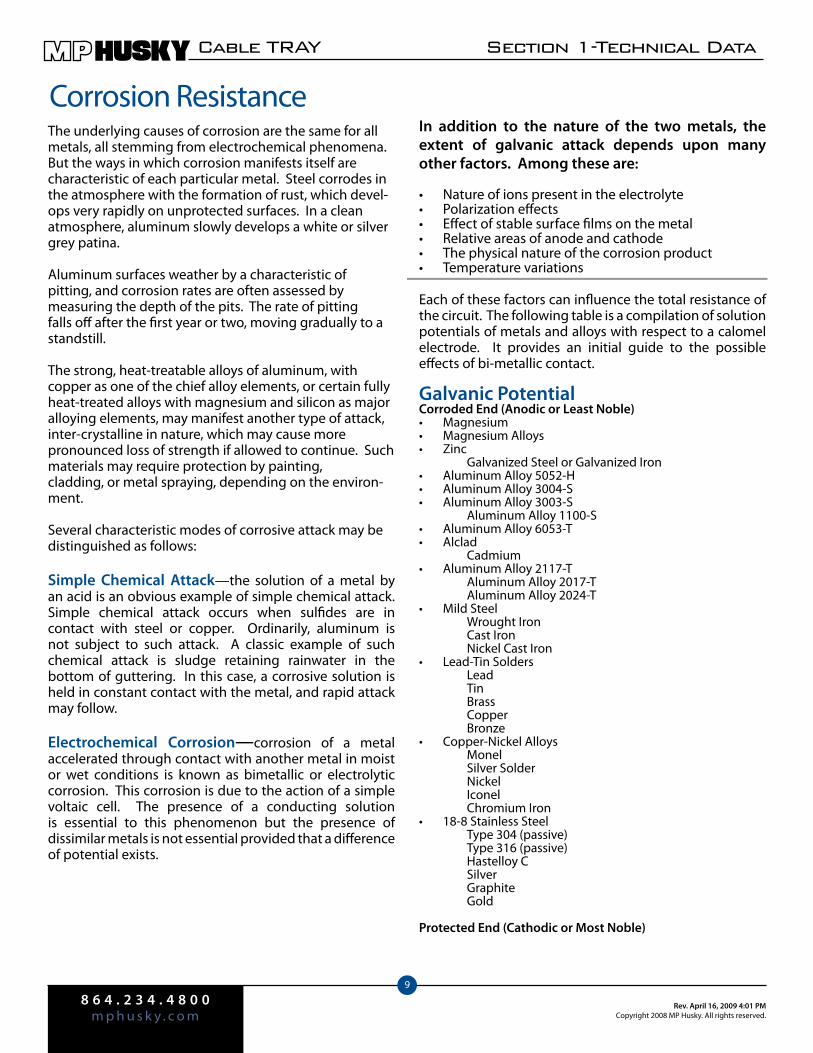
Each of these factors can influence the total resistance of the circuit. The following table is a compilation of solution potentials of metals and alloys with respect to a calomel electrode. It provides an initial guide to the possible effects of bi-metallic contact.
Galvanic PotentialCorroded End (Anodic or Least Noble)
Magnesium•Magnesium Alloys•Zinc•
Galvanized Steel or Galvanized IronAluminum Alloy 5052-H•Aluminum Alloy 3004-S•Aluminum Alloy 3003-S•
Aluminum Alloy 1100-SAluminum Alloy 6053-T•Alclad•
CadmiumAluminum Alloy 2117-T•
Aluminum Alloy 2017-T Aluminum Alloy 2024-T
Mild Steel • Wrought Iron Cast Iron Nickel Cast Iron
Lead-Tin Solders• Lead Tin Brass Copper Bronze
Copper-Nickel Alloys• Monel Silver Solder Nickel Iconel Chromium Iron
18-8 Stainless Steel• Type 304 (passive) Type 316 (passive) Hastelloy C Silver Graphite Gold
Protected End (Cathodic or Most Noble)
8 6 4 . 2 3 4 . 4 8 0 0m p h u s k y . c o m
Rev. April 16, 2009 4:01 PMCopyright 2008 MP Husky. All rights reserved.
Cable TRAY Section 1-Technical Data
10
Corrosion ResistanceThe composition of the base metals has no measur-able effect on the life of zinc coatings. However, the composition of the base metals is the major factor in the years to perforation.
The corrosion rate of zinc varies more with the type of atmosphere (marine, industrial) than does that of steel or iron.
The chloride content of sea air apparently has an accelerating effect on the corrosion of zinc coating.
Rainfall removes about 75% of the corrosion products from zinc surfaces if the results of tests in rural, indus-trial and marine exposures are averaged together. The residual corrosion products remaining on the surface be-come basic in character and exert a retarding influence on corrosion. In highly industrialized or polluted atmo-spheres, this basic film may not exist, a fact which helps explain the more rapid attack experienced in such atmospheres.
Indoor atmospheres correspond in a general way to that prevailing outside in a given locality. Variations in humidity and temperature are somewhat less ex-treme and there is no rainfall indoors to dissolve and remove soluble corrosion products. In general, it may be assumed that the protective life of zinc coatings indoors is at least five times greater than that of coatings of the same thickness exposed to the outdoor atmosphere in the same locality.
The indoor corrosion of zinc may be severe when moisture condensation is frequent and air circulation is restricted. This effect is particularly bad in humid, tropical locations with nightly condensation.
These conclusions indicate zinc coatings will in any event have an acceptable service life expectancy regardless of how the end point of failure is defined. However, it should be noted that whenever maintenance, such as painting, is neglected, it is unreasonable to expect galvanized steel to last indefinitely.
Finishes
MetallicCable trays fabricated of steel can be protected from corrosion by coating with another metal using one of the following methods:
Continuous Hot-Rolled Galvanizing• ASTM Designation Specifications for Zinc Coated Galvanized) Iron or Steel Sheets, Coils, and Cut Lengths—This process applies a zinc coating to sheet steel prior to fabrication of the product (pre-galva-nized cable tray) by passing the metal downward through a molten ammonium chloride flux bath, and then into the zinc and out again by means of rolls. The MPHusky standard zinc coating designation is G90, which has an average zinc coating weight of 1.25 ounces per square foot of steel for an average coating on both surfaces of 1.06 mils.
Hot Dipped Galvanizing After Fabrication• ASTM Designation A123 Specification for Zinc Coat-ing (Hot Dip) on Assembled Steel Products—This process is used to apply a zinc coating to an already fabricated product. The product is first cleaned in a caustic bath, then further cleaned by a pickling acid bath. The article is then thoroughly rinsed and dipped in a bath of molten zinc. The nature and thickness of the coating depend largely on the im-mersion rate, temperature of the bath, immersion period, and withdrawal rate. The resulting coating consists of an outer layer of relatively pure zinc, and lower layers of iron-zinc compounds. Generally, hot dip coatings are highly non-uniform, except on very simple shapes and are usually thick-est at small recesses (unless these remain uncoated altogether). The advantage of this method is that the zinc applied is thicker than when applied by other processes. However, the protective characteristics of zinc coating under atmospheric conditions have been found to be equal, regardless of process: i.e. zinc coatings of the same weight have approximately the same service life.
Galvannealed• Galvannealed or Galvanneal, is the result from the combined process of galvanizing and annealing the steel. The galvanization is made through the hot-dip-ping (hot-dip galvanizing) process and gives a very fine grayish matte finish. Galvanneal does not flake off its galvanized coating when formed, stamped, and bent.
8 6 4 . 2 3 4 . 4 8 0 0m p h u s k y . c o mRev. April 16, 2009 4:01 PM
Copyright 2008 MP Husky. All rights reserved.
Section 1-Technical Data CABLE TRAY
11
The corrosive nature of sea water and of coastal envi-ronments is partly due to the low electrical resistance of salt solution. Similarly, the bad effects of industrial atmospheres on metals arise largely from the sulphur compounds, sulphurous and sulfuric acids, which are largely formed as a result of burning coal, and which dissolve in the moisture in the air or in the rain as it falls, or in films of condensed water on the metal.
To summarize, the extent and type of moisture is an important factor in determining the severity of galvanic attack. For indoor service, where wetting is infrequent, galvanic corrosion normally is no problem. Outdoors, attack may be relatively rapid in sea coast and industrial environments, where contamination, hence conduc-tivity, of rain and condensed moisture is high. Several general rules can be applied in selecting metal combi-nations for use in corrosive environments. These are:
Select metals as close together in the galvanic series as possible. For the anodic protection of steel, metals above steel in the series should be selected, or the steel should be galvanized or otherwise protective-coated. Avoid combinations having a smaller area of the more anodic metal than of the cathodic, to avoid excessive current density on the anodic areas. Insulate dissimilar metals wherever possible to minimize galvanic corrosion.
Aluminum AlloysThe corrosion-resistance of aluminum alloys is due to the presence on the surface of a very thin protective film of aluminum oxide which has strong self-healing properties when damaged. The oxide film begins to form immediately on the surface of the bare metal exposed to air and grows rapidly for several days, then slowly for a month, when it reaches a thickness of approximately 0.0000002”. Corrosion of aluminum can only occur when the oxide film is damaged or removed and conditions prevent its formation.
Substances which may come in contact with aluminum can be divided into three groups:
Those substances which attack the oxide film. These are most strong alkalis, mercurial compounds, and most strong acids.
Substances which cause localized breakdown of the oxide film (pitting) - and for which aluminum is suitable only under certain conditions, such as some natural fresh waters and aqueous solutions containing traces of mercury, copper, or other heavy metals.
Corrosion ResistanceSubstances which do not attack the oxide film. The majority of substances fall in this group, including many industrial chemicals.
The majority of aluminum installations give perfectly satisfactory service, free from corrosion, and only in exceptional cases do problems occur. When problems do occur, they can be attributed to one or more of the following causes:
Wrong choice of alloy•Exposure conditions•A bimetallic joint which causes galvanic corrosion•Crevices•Unwise location of the aluminum assembly, resulting •in deposition corrosionContact with aggressive chemicals•
Among the heat-treatable alloys, the 6000 series has good resistance to industrial and marine atmospheres.
With the exception of certain corrosive chemicals, no corrosion at all will occur if water is not present. Thus, indoor installations that are not in actual contact with water or installations which are maintained in dry conditions, will not corrode.
Steel with Zinc CoatingsThe data from which comparative performance of different types of zinc coating can be inferred, are generally obtained from comprehensive exposure tests in various atmospheres, such as those conducted since 1926 by the American Society of Testing Materials. From the results of these tests, the following conclusions can be made:
The corrosion rate of zinc on galvanized sheets is practically linear in industrial or rural atmospheres, and in a marine atmosphere that is polluted with industrial contaminants. Thus, in these atmospheres, a sheet with double the weight of coating than that of another sheet can be expected to last twice as long before rusting of the base metal occurs.
8 6 4 . 2 3 4 . 4 8 0 0m p h u s k y . c o mRev. April 16, 2009 4:01 PM
Copyright 2008 MP Husky. All rights reserved.
Section 1-Technical Data CABLE TRAY
12
LoadingThis section presents guidelines for classification of design conditions with respect to weather factors, meth-ods of determination and application of various types of loadings encountered, maximum allowable work-ing stresses and other pertinent considerations. This information will assist the designer in evaluating ma-terials and product catalog information so that he can design a system which will achieve the desired strength and rigidity at the lowest possible installed cost.
Load ClassificationLoads on structures are usually divided into three types:
Dead loads• that do not change their magnitude or their position during the life of the structure.Live loads• that change their magnitude, their position and/or their direction during the life of the structure.Dynamic loads• that are caused by the motion of the live load, or the movement of the structure.
Because of their general nature, these load classifica-tions can be used for any structure. However, for the purpose of establishing a practical load classification for cable tray system design, it is necessary to create additional subdivisions and provide a guide for assumption of specific loads.
Thus, for cable tray system design, the three basic load types are also considered as follows:
Dead LoadsSince dead loads are the weight of the members that make up a tray or tray support, they have a known value. A summation of the weights of the individual members is all that is required to calculate the dead load.
Live LoadsIn cable tray design, dynamic loads are considered to be as follows:
The design load is the weight of cables, cable tray •accessories, and sometimes workers (which vary in both magnitude and position). Cable only design loads can be determined by adding the component weights of the system. Any provision for workers will require an assumption of magnitude and position—for practical purposes, an assigned weight acting at mid span of the tray.
Parasitic loads such as ice, snow, wind, traction, and •electromagnetic forces exist only because the tray exist. They are the most difficult to determine, and different assumptions can be made about their effect on the overall loadings. The following information will provide a general guide.
8 6 4 . 2 3 4 . 4 8 0 0m p h u s k y . c o m
Rev. April 16, 2009 4:01 PMCopyright 2008 MP Husky. All rights reserved.
Cable TRAY Section 1-Technical Data
13
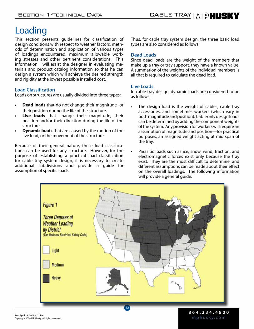
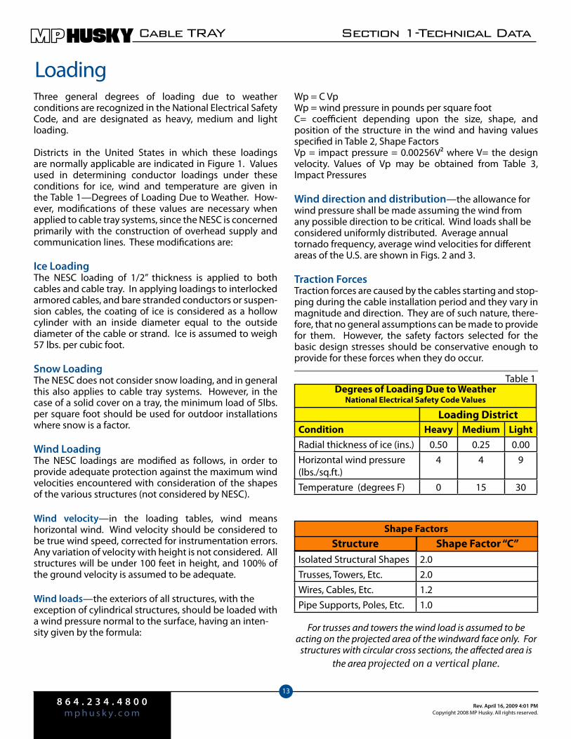
Three general degrees of loading due to weather conditions are recognized in the National Electrical Safety Code, and are designated as heavy, medium and light loading.
Districts in the United States in which these loadings are normally applicable are indicated in Figure 1. Values used in determining conductor loadings under these conditions for ice, wind and temperature are given in the Table 1—Degrees of Loading Due to Weather. How-ever, modifications of these values are necessary when applied to cable tray systems, since the NESC is concerned primarily with the construction of overhead supply and communication lines. These modifications are:
Ice LoadingThe NESC loading of 1/2” thickness is applied to both cables and cable tray. In applying loadings to interlocked armored cables, and bare stranded conductors or suspen-sion cables, the coating of ice is considered as a hollow cylinder with an inside diameter equal to the outside diameter of the cable or strand. Ice is assumed to weigh 57 lbs. per cubic foot.
Snow LoadingThe NESC does not consider snow loading, and in general this also applies to cable tray systems. However, in the case of a solid cover on a tray, the minimum load of 5lbs. per square foot should be used for outdoor installations where snow is a factor.
Wind LoadingThe NESC loadings are modified as follows, in order to provide adequate protection against the maximum wind velocities encountered with consideration of the shapes of the various structures (not considered by NESC).
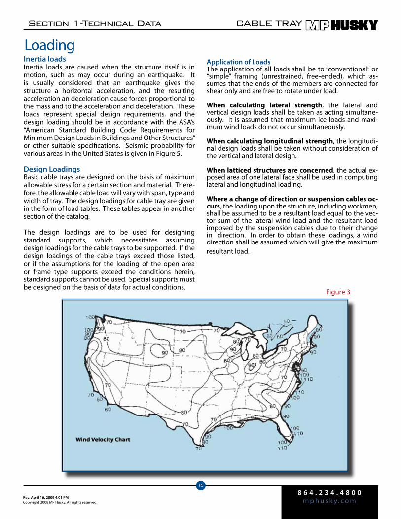
Wind velocity—in the loading tables, wind means horizontal wind. Wind velocity should be considered to be true wind speed, corrected for instrumentation errors. Any variation of velocity with height is not considered. All structures will be under 100 feet in height, and 100% of the ground velocity is assumed to be adequate.
Wind loads—the exteriors of all structures, with the exception of cylindrical structures, should be loaded with a wind pressure normal to the surface, having an inten-sity given by the formula:
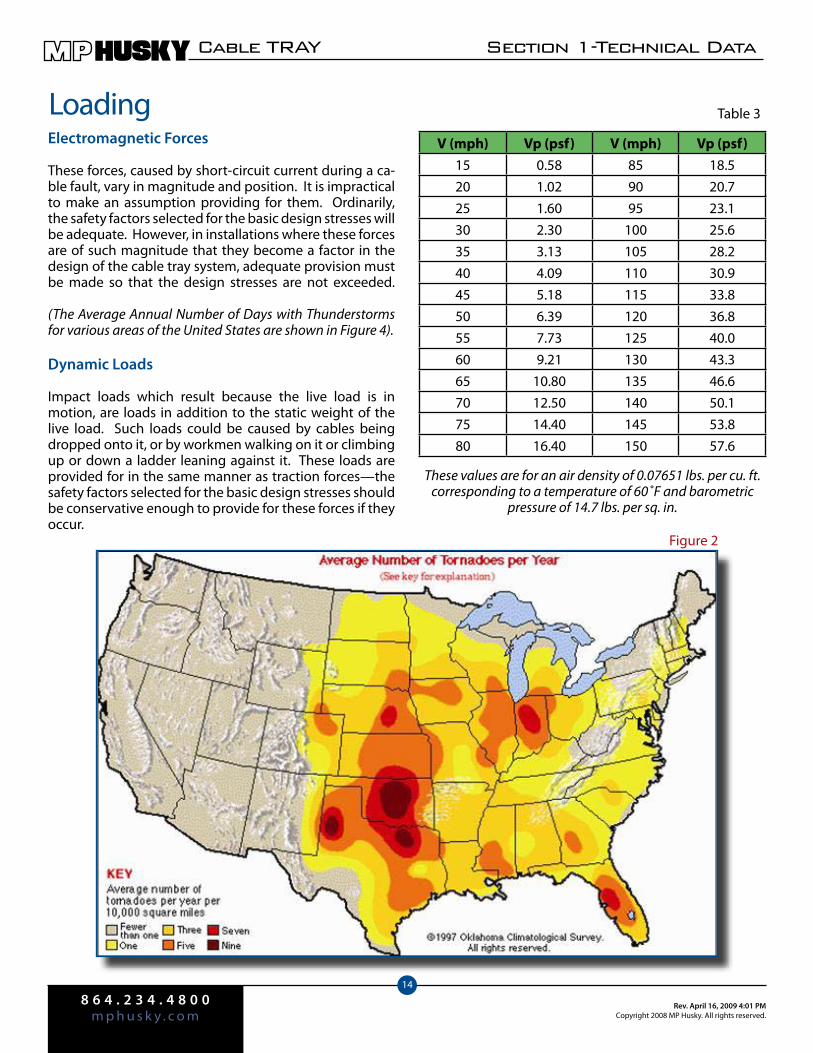
LoadingWp = C VpWp = wind pressure in pounds per square footC= coefficient depending upon the size, shape, and position of the structure in the wind and having values specified in Table 2, Shape FactorsVp = impact pressure = 0.00256V² where V= the design velocity. Values of Vp may be obtained from Table 3, Impact Pressures
Wind direction and distribution—the allowance for wind pressure shall be made assuming the wind from any possible direction to be critical. Wind loads shall be considered uniformly distributed. Average annual tornado frequency, average wind velocities for different areas of the U.S. are shown in Figs. 2 and 3.
Traction ForcesTraction forces are caused by the cables starting and stop-ping during the cable installation period and they vary in magnitude and direction. They are of such nature, there-fore, that no general assumptions can be made to provide for them. However, the safety factors selected for the basic design stresses should be conservative enough to provide for these forces when they do occur.
Condition Heavy Medium LightRadial thickness of ice (ins.) 0.50 0.25 0.00Horizontal wind pressure(lbs./sq.ft.)
4 4 9
Temperature (degrees F) 0 15 30
Isolated Structural Shapes 2.0Trusses, Towers, Etc. 2.0Wires, Cables, Etc. 1.2Pipe Supports, Poles, Etc. 1.0
Loading District
Degrees of Loading Due to Weather National Electrical Safety Code Values
Structure Shape Factor “C”Shape Factors
For trusses and towers the wind load is assumed to be acting on the projected area of the windward face only. For
structures with circular cross sections, the affected area is the area projected on a vertical plane.
Table 1
8 6 4 . 2 3 4 . 4 8 0 0m p h u s k y . c o m
Rev. April 16, 2009 4:01 PMCopyright 2008 MP Husky. All rights reserved.
Cable TRAY Section 1-Technical Data
14
Electromagnetic Forces
These forces, caused by short-circuit current during a ca-ble fault, vary in magnitude and position. It is impractical to make an assumption providing for them. Ordinarily, the safety factors selected for the basic design stresses will be adequate. However, in installations where these forces are of such magnitude that they become a factor in the design of the cable tray system, adequate provision must be made so that the design stresses are not exceeded.
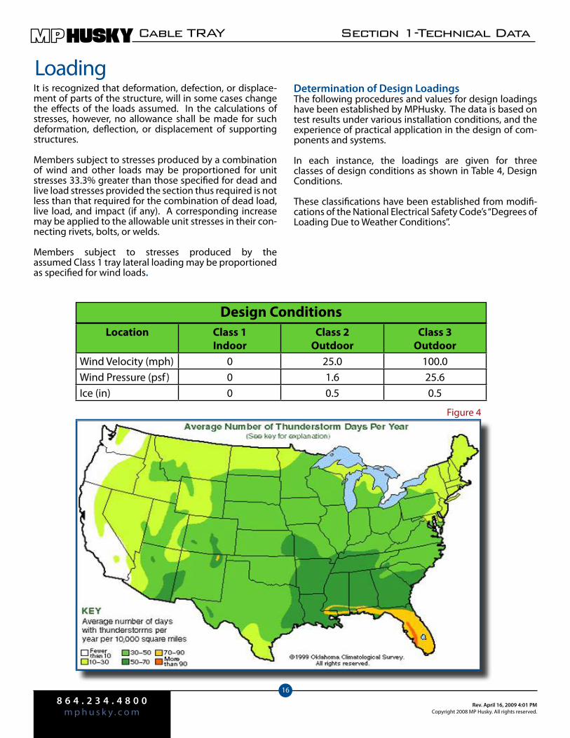
(The Average Annual Number of Days with Thunderstorms for various areas of the United States are shown in Figure 4).
Dynamic Loads
Impact loads which result because the live load is in motion, are loads in addition to the static weight of the live load. Such loads could be caused by cables being dropped onto it, or by workmen walking on it or climbing up or down a ladder leaning against it. These loads are provided for in the same manner as traction forces—the safety factors selected for the basic design stresses should be conservative enough to provide for these forces if they occur.
LoadingV (mph) Vp (psf) V (mph) Vp (psf)
15 0.58 85 18.520 1.02 90 20.725 1.60 95 23.130 2.30 100 25.635 3.13 105 28.240 4.09 110 30.945 5.18 115 33.850 6.39 120 36.855 7.73 125 40.060 9.21 130 43.365 10.80 135 46.670 12.50 140 50.175 14.40 145 53.880 16.40 150 57.6
These values are for an air density of 0.07651 lbs. per cu. ft. corresponding to a temperature of 60˚F and barometric
pressure of 14.7 lbs. per sq. in.
Table 3
Figure 2
8 6 4 . 2 3 4 . 4 8 0 0m p h u s k y . c o mRev. April 16, 2009 4:01 PM
Copyright 2008 MP Husky. All rights reserved.
Section 1-Technical Data CABLE TRAY
15
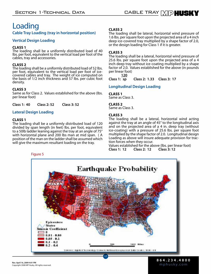
Inertia loadsInertia loads are caused when the structure itself is in motion, such as may occur during an earthquake. It is usually considered that an earthquake gives the structure a horizontal acceleration, and the resulting acceleration an deceleration cause forces proportional to the mass and to the acceleration and deceleration. These loads represent special design requirements, and the design loading should be in accordance with the ASA’s “American Standard Building Code Requirements for Minimum Design Loads in Buildings and Other Structures” or other suitable specifications. Seismic probability for various areas in the United States is given in Figure 5.
Design LoadingsBasic cable trays are designed on the basis of maximum allowable stress for a certain section and material. There-fore, the allowable cable load will vary with span, type and width of tray. The design loadings for cable tray are given in the form of load tables. These tables appear in another section of the catalog.
The design loadings are to be used for designing standard supports, which necessitates assuming design loadings for the cable trays to be supported. If the design loadings of the cable trays exceed those listed, or if the assumptions for the loading of the open area or frame type supports exceed the conditions herein, standard supports cannot be used. Special supports must be designed on the basis of data for actual conditions.
LoadingApplication of LoadsThe application of all loads shall be to “conventional” or “simple” framing (unrestrained, free-ended), which as-sumes that the ends of the members are connected for shear only and are free to rotate under load.
When calculating lateral strength, the lateral and vertical design loads shall be taken as acting simultane-ously. It is assumed that maximum ice loads and maxi-mum wind loads do not occur simultaneously.
When calculating longitudinal strength, the longitudi-nal design loads shall be taken without consideration of the vertical and lateral design.
When latticed structures are concerned, the actual ex-posed area of one lateral face shall be used in computing lateral and longitudinal loading.
Where a change of direction or suspension cables oc-curs, the loading upon the structure, including workmen, shall be assumed to be a resultant load equal to the vec-tor sum of the lateral wind load and the resultant load imposed by the suspension cables due to their change in direction. In order to obtain these loadings, a wind direction shall be assumed which will give the maximum resultant load.
Figure 3
8 6 4 . 2 3 4 . 4 8 0 0m p h u s k y . c o m
Rev. April 16, 2009 4:01 PMCopyright 2008 MP Husky. All rights reserved.
Cable TRAY Section 1-Technical Data
16
It is recognized that deformation, defection, or displace-ment of parts of the structure, will in some cases change the effects of the loads assumed. In the calculations of stresses, however, no allowance shall be made for such deformation, deflection, or displacement of supporting structures.
Members subject to stresses produced by a combination of wind and other loads may be proportioned for unit stresses 33.3% greater than those specified for dead and live load stresses provided the section thus required is not less than that required for the combination of dead load, live load, and impact (if any). A corresponding increase may be applied to the allowable unit stresses in their con-necting rivets, bolts, or welds.
Members subject to stresses produced by the assumed Class 1 tray lateral loading may be proportioned as specified for wind loads.
LoadingDetermination of Design LoadingsThe following procedures and values for design loadings have been established by MPHusky. The data is based on test results under various installation conditions, and the experience of practical application in the design of com-ponents and systems.
In each instance, the loadings are given for three classes of design conditions as shown in Table 4, Design Conditions.
These classifications have been established from modifi-cations of the National Electrical Safety Code’s “Degrees of Loading Due to Weather Conditions”.
Location Class 1Indoor
Class 2Outdoor
Class 3Outdoor
Wind Velocity (mph) 0 25.0 100.0Wind Pressure (psf ) 0 1.6 25.6Ice (in) 0 0.5 0.5
Design Conditions
Figure 4
8 6 4 . 2 3 4 . 4 8 0 0m p h u s k y . c o mRev. April 16, 2009 4:01 PM
Copyright 2008 MP Husky. All rights reserved.
Section 1-Technical Data CABLE TRAY
17
Cable Tray Loading (tray in horizontal position)
Vertical Design Loading CLASS 1The loading shall be a uniformly distributed load of 40 lbs. per foot, equivalent to the vertical load per foot of the cables, tray and accessories.
CLASS 2The loading shall be a uniformly distributed load of 52 lbs. per foot, equivalent to the vertical load per foot of ice-covered cables and tray. The weight of ice computed on the basis of 1/2 inch thickness and 57 lbs. per cubic foot density.
CLASS 3Same as for Class 2. Values established for the above (lbs. per linear foot)
Class 1: 40 Class 2: 52 Class 3: 52
Lateral Design Loading CLASS 1The loading shall be a uniformly distributed load of 120 divided by span length (in feet) lbs. per foot, equivalent to a 50lb ladder leaning against the tray at an angle of 75° with horizontal plane and 200 lbs man at mid span. ( A position of the man on the ladder shall be assumed which will give the maximum resultant loading on the tray.
Loading CLASS 2The loading shall be lateral, horizontal wind pressure of 1.6 lbs. per square foot upon the projected area of a 4 inch deep ice-covered tray multiplied by a shape factor of 2.0, or the design loading for Class 1 if it is greater.
CLASS 3The loading shall be a lateral, horizontal wind pressure of 25.6 lbs. per square foot upon the projected area of a 4 inch deep tray without ice-coating multiplied by a shape factor of 2.0. Values established for the above (in pounds per linear foot) 120Class 1: sp Class 2: 1.33 Class 3: 17
Longitudinal Design Loading
CLASS 1Same as Class 3.
CLASS 2Same as Class 3.
CLASS 3The loading shall be a lateral, horizontal wind acting against the tray at an angle of 45° to the longitudinal axis and on the projected area of a 4 in. deep tray (without ice-coating) with a pressure of 25.6 lbs. per square foot multiplied by the shape factor of 2.0. Longitudinal design Loading as above will insure adequate provision for trac-tion forces when they occur.Values established for the above (lbs. per linear foot)Class 1: 12 Class 2: 12 Class 3: 12
Figure 5
8 6 4 . 2 3 4 . 4 8 0 0m p h u s k y . c o m
Rev. April 16, 2009 4:01 PMCopyright 2008 MP Husky. All rights reserved.
Cable TRAY Section 1-Technical Data
18
The concept of “Cables in Free Air” for power distribu-tion and control cables has been adopted primarily for economic reasons. Cable tray support systems should be designed, whenever possible, for minimum installed cost. In order to achieve this objective, the engineer must bear in mind that the general design rules established for aluminum and steel structures are not always compatible with design rules for a cable tray system. This is particu-larly applicable in the case of restrictions on deflection.
Since the most economical cable tray system uses heat treated aluminum alloys, or high strength steels with long spans, any limitation on deflection which will not permit the best utilization of material and design will increase the cost. By limiting the maximum fiber and shear stress used in the design the adequacy and safety of the struc-ture is assured.
Why Limit Deflection?The primary reason to limit deflection in cable tray systems is appearance. Engineers and owners take pride in the appearance of their installations. So rigid restrictions on deflection of cable trays installed at eye level or in a prominent location are common. However, it is neither economical nor good engineering practice to restrict deflection of a cable tray system in less prominent areas.
Methods of Decreasing DeflectionThere are various ways to limit deflection of a cable tray. If the objective is minimal installed cost, they should be considered in this order:
Decreasing stress by decreasing the bending •moment. This can be accomplished by introduc-ing restraining moments at the end of a span in the form of a rigid support. The deflection in a continu-ous beam, with negative bending moments at the intermediate support points, is only a fraction of the deflection in a simple beam.
Increasing depth of the tray. • Deflection in any loca-tion can be reduced by increasing the depth of the load-carrying side members and/or by adding to their cross-sectional area. Adding to the depth generally utilizes the material most economically.
Increasing modulus of elasticity. • Since the mod-ulus of elasticity of steel is 29 x 106 psi, and that of aluminum alloys is only 10 x 106 psi, greater defor-mation of aluminum alloy trays is to be expected at any given stress level. Under its own weight, an aluminum beam will defect the same amount as an identical steel beam, since not only the weight, but also the modulus of elasticity is only one-third that of steel. However, under the same applied load (disregarding the beam’s own weight), aluminum will deflect almost three times as much as steel.
Loading(cont’d) Therefore, consideration must be given to the •choice of material for any one location, for an isolated run or for an entire installation.
Decreasing span length. • For economic reasons, this method of reducing deflection should be a last resort, since it increases field labor considerably. However, it can be an effective means to improve the appear-ance of an installation when the number of spans to be reduced is small in comparison to the number in the entire installation.
Deflection Criteria Applied to Cable TrayDesign rules and specifications developed for steel should not be applied to aluminum alloys since this would not permit the most economical use of these materials. De-flection criteria which apply only to steel, and should not be used when the most economical system is desired in-clude:
Span-deflection ratio• - Example: Deflection is limited to 1/300 of the span by the National Electrical Manufacturers Association specifications for structures supporting air switches. While very important in that instance, as even slight deflec-tion could cause misalignment in the operating mechanism and result in binding and difficult switch operation, the application of this specification to a cable tray is uneconomical and not recommended.
Depth to span ratio• - Example: The American Institute of Steel Construction, in the specifications for buildings, specifies the depths of beams and girders in floors to be not less that 1/24 of the span, or not less than 1/20 of the span where shock or vibration may be encountered. This specifica-tion ensures a certain rigidity and levelness of the structure which is important in that in-stance, but cannot be justified for cable tray systems because of the higher cost involved.
Deflection constant• - Example: Deflection is limited to a certain amount by an engineering company for a tray system. While such specifications might make a system using 8-foot spans look better, it prohibits the use of more economical designs with longer spans which have a much greater deflection and still look acceptable. Such a specification increases the cost of the tray system unnecessarily, especially if the trays are to be installed well above eye level.
SummaryAs a guide, a span-deflection ratio of around 1/200 satisfies most owners. This ratio provides an allowable deflection of 0.6” in a 10-foot span, 0.72” in a 12-foot span, and 1.20” in a 20-foot span under the actual loads encountered. Data for calculating deflection is presented in Table 5, Constants for Beam Deflections.
8 6 4 . 2 3 4 . 4 8 0 0m p h u s k y . c o mRev. April 16, 2009 4:01 PM
Copyright 2008 MP Husky. All rights reserved.
Section 1-Technical Data CABLE TRAY
19
5 Span
Deflection
2 Span 3 Span
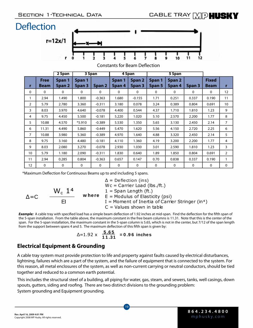
Constants for Beam Deflection
Wc 1
EI Δ=C
where
Δ = Deflection (ins) Wc = Carrier Load (lbs./ft.) 1 = Span Length (ft.) E = Modulus of Elasticity (psi) I = Moment of Inertia of Carrier Stringer (in) C = Values shown in table
4 Span
rFree
BeamSpan 1Span 2
Span 1Span 3 Span 2
Span 1Span 4
Span 2Span 3
Span 1Span 5
Span 2Span 4 Span 3
Fixed Beam r
0 0 0 0 0 0 0 0 0 0 0 12
1 2.94 1.490 1.800 -0.363 1.680 -0.155 1.71 0.251 0.337 0.190 11
2 5.79 2.780 3.360 -0.311 3.180 0.078 3.24 0.389 0.804 0.691 10
3 8.03 3.970 4.640 -0.078 4.400 0.544 4.37 1.710 1.810 1.23 9
4 9.75 4.450 5.500 -0.181 5.220 1.020 5.10 2.570 2.200 1.77 8
5 10.88 4.570 *5.910 -0.389 5.530 1.350 5.65 3.130 2.450 2.14 7
6 11.31 4.490 5.860 -0.449 5.470 1.620 5.56 4.150 2.720 2.25 6
7 10.88 3.980 5.360 -0.389 4.970 1.640 4.88 3.320 2.450 2.14 5
8 9.75 3.160 4.480 -0.181 4.110 1.360 4.19 3.200 2.200 1.77 4
9 8.03 2.080 3.270 -0.078 2.930 1.030 3.01 2.590 1.810 1.23 3
10 5.79 1.180 2.090 -0.311 1.830 0.640 1.89 1.850 0.804 0.691 2
11 2.94 0.285 0.804 -0.363 0.657 0.147 0.70 0.838 0.337 0.190 1
12 0 0 0 0 0 0 0 0 0 0 0
*Maximum Deflection for Continuous Beams up to and including 5 spans.
__________
Example: A cable tray with specified load has a simple beam deflection of 1.92 inches at mid-span. Find the deflection for the fifth span of the 5-span installation. From the table above, the maximum constant in the free beam columns is 11.31. Note that this is the center of the span. For the 5-span installation, the maximum constant in the 5-span column is 5.65, which is not in the center, but 7/12 of the span length from the support between spans 4 and 5. The maximum deflection of this fifth span is given by:
A cable tray system must provide protection to life and property against faults caused by electrical disturbances, lightning, failures which are a part of the system, and the failure of equipment that is connected to the system. For this reason, all metal enclosures of the system, as well as non-current carrying or neutral conductors, should be tied together and reduced to a common earth potential.
This includes the structural steel of a building, all piping for water, gas, steam, and sewers, tanks, well casings, down spouts, gutters, siding and roofing. There are two distinct divisions to the grounding problem: System grounding and Equipment grounding.
Δ=1.92 x 5.65 11.31 =0.96 inches
Electrical Equipment & Grounding
8 6 4 . 2 3 4 . 4 8 0 0m p h u s k y . c o m
Rev. April 16, 2009 4:01 PMCopyright 2008 MP Husky. All rights reserved.
Cable TRAY Section 1-Technical Data
20
Electrical Design & GroundingThe following explanation gives the reasons for grounding, and how to provide for it.
System GroundingThe purpose of system grounding is to drain off any excessively high voltages that may accidentally come on the tray system. If the system is properly grounded by means of a low-resistance conductor of sufficient capacity, the current will be carried off to earth immediately with a minimum danger of fire or shock. In a grounded system, an accidental grounding of one of the current carrying conductors will result in a short circuit, and cause a fuse or circuit breaker to open.
Equipment GroundingEquipment grounding means the connection to earth of all exposed, non-current carrying metallic parts of the components of the distribution system. The purpose of this ground is to prevent a voltage higher than earth potential on cable tray or equipment. Grounding thus reduces the danger of shock or fire in the event a live conductor comes in contact with these conductive parts.
Methods of GroundingEffective grounding must be permanent and continuous, and have ample capacity to safety conduct any current likely to be imposed on it. It should also have impedance sufficiently low to limit the potential above ground and to facilitate operation of over-current devices in the circuit. A continuous, underground metallic water supply system is acknowledged to be the best electrical ground. Other suitable methods of grounding include continuous metallic steam and gas piping systems, the grounded metal framing of the building, or an artificial electrode such as a driven steel pipe, galvanized or otherwise protected from corrosion, or a buried metallic plate.
The tray system and equipment ground connections should be made to the same electrode at the service entrance, on the supply side of the equipment used for disconnecting the service. Equipment should be solidly tied in with the system ground. It is also important, that wherever multiple grounds are used, they be tied together in order to avoid any difference of potential between the various parts of the tray system.
Complete rules for grounding are contained in Article 250 of the National Electric Code.
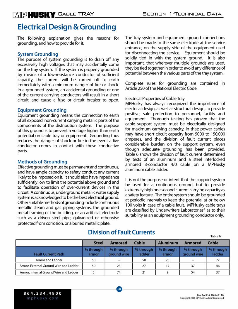
Electrical Properties of Cable TrayMPHusky has always recognized the importance of electrical design, as well as structural design, to provide positive, safe protection to personnel, facility and equipment. Thorough testing has proven that the cable support system must be electrically designed for maximum carrying capacity, in that: power cables may have short circuit capacity from 5000 to 150,000 amperes, and the division of fault current places considerable burden on the support system, even though adequate grounding has been provided. Table 6 shows the division of fault current determined by tests of an aluminum and a steel interlocked armored 3-conductor 4/0 cable on a MPHusky aluminum cable ladder.
It is not the purpose or intent that the support system be used for a continuous ground, but to provide extremely high one second current carrying capacity as a safety feature. The entire system should be grounded at periodic intervals to keep the potential at or below 100 volts in case of a cable fault. MPHusky cable trays are classified by Underwriters Laboratories® as to their suitability as an equipment grounding conductor only.
Division of Fault Currents Table 6
Steel Armored Cable Aluminum Armored Cable
Fault Current Path% through
armor% through
ground wire% through
ladder% through
armor% through
ground wire% through
ladderArmor and Ladder 50 -- 50 23 -- 77
Armor, External Ground Wire and Ladder 50 23 27 17 37 46
Armor, Internal Ground Wire and Ladder 5 74 21 9 54 37
8 6 4 . 2 3 4 . 4 8 0 0m p h u s k y . c o mRev. April 16, 2009 4:01 PM
Copyright 2008 MP Husky. All rights reserved.
Section 1-Technical Data CABLE TRAY
21
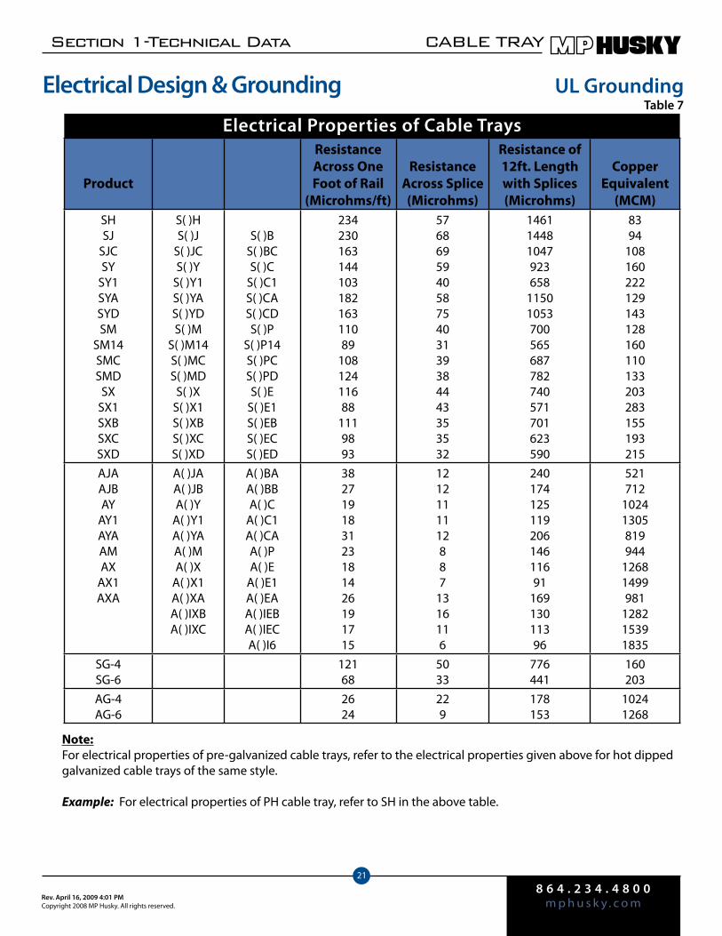
Electrical Properties of Cable Trays
Note:For electrical properties of pre-galvanized cable trays, refer to the electrical properties given above for hot dipped galvanized cable trays of the same style. Example: For electrical properties of PH cable tray, refer to SH in the above table.
UL GroundingTable 7
Electrical Design & Grounding
Product
Resistance Across One Foot of Rail
(Microhms/ft)
Resistance Across Splice (Microhms)
Resistance of 12ft. Length with Splices (Microhms)
CopperEquivalent
(MCM)SHSJ
SJCSY
SY1SYASYDSM
SM14SMCSMD
SXSX1SXBSXCSXD
S( )HS( )J
S( )JCS( )Y
S( )Y1S( )YAS( )YDS( )M
S( )M14S( )MCS( )MD
S( )XS( )X1S( )XBS( )XCS( )XD
S( )BS( )BCS( )C
S( )C1S( )CAS( )CDS( )P
S( )P14S( )PCS( )PDS( )E
S( )E1S( )EBS( )ECS( )ED
23423016314410318216311089
10812411688
1119893
57686959405875403139384443353532
146114481047923658
11501053700565687782740571701623590
8394
108160222129143128160110133203283155193215
AJAAJBAY
AY1AYAAMAX
AX1AXA
A( )JAA( )JBA( )Y
A( )Y1A( )YAA( )MA( )X
A( )X1A( )XAA( )IXBA( )IXC
A( )BAA( )BBA( )C
A( )C1A( )CAA( )PA( )E
A( )E1A( )EAA( )IEBA( )IECA( )I6
382719183123181426191715
1212111112887
1316116
24017412511920614611691
16913011396
521712
10241305819944
12681499981
128215391835
SG-4SG-6
12168
5033
776441
160203
AG-4AG-6
2624
229
178153
10241268
8 6 4 . 2 3 4 . 4 8 0 0m p h u s k y . c o m
Rev. April 16, 2009 4:01 PMCopyright 2008 MP Husky. All rights reserved.
Cable TRAY Section 1-Technical Data
22
Sizing Trays for Multiple-Conductor Cables
Section 392.2 lists the requirements for installing multiple-conductor cables in ladder, ventilated trough, solid-bottom, or ventilated channel type trays.
For ladder or ventilated trough trays, the diam-eter of all cables No. 4/0 and larger must be added together and the total must not exceed the width of the cable tray. Cables must be placed side by side. Table 392.9, Column 1 is used for cables less than 4/0. These cables do not have to be placed side by side. Table 392.9, Column 2 is used for a combination of cables rat-ed larger than 4/0 and smaller than 4/0.
The total cross-sectional areas of the cables in trays with an inside depth of 6” or less, containing control and/or signal cables must not exceed 50% of the cross-section-al area of the tray.
For solid bottom trays, the diameter of all cables No. 4/0 and larger must not exceed 90% of the cable tray width. Table 392.9, Column 3 is used for cables smaller than 4/0. Table 392.9, Column 4 is used for a combination of cables rated 4/0 or larger, or less than 4/0.
For trays with an inside depth of 6 inches or less, containing control and/or signal cables, the to-tal cross-sectional areas of the cables must not exceed 40% of the cross-sectional area of the tray.
For ventilated channel type trays, the total cross-sec-tional areas of all cables must not exceed 2.5 square inches for 3 inch wide trays or 3.8 square inches for 6 inch wide trays.
Sizing Trays for Single Conductor Cables
For ladder or ventilated trough trays, the total diameter of all cables 1000MCM and larger must not exceed the width of the cable tray. Table 392.10, Column 1 is used for cables smaller than 1000MCM. Tables 392.10, Column 2 is used for a combination of cables rated 1000MCM and larger, and smaller than 1000MCM.
For ventilated channel type trays, the total diameter of all cables must not exceed the inside width of 4” or 6” wide trays.
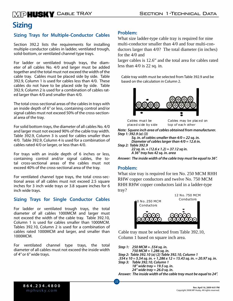
SizingProblem:What size ladder-type cable tray is required for nine multi-conductor smaller than 4/0 and four multi-con-ductors larger than 4/0? The total diameter (in inches) for the 4/0 and larger cables is 12.6” and the total area for cables rated less than 4/0 is 22 sq. in.
Note: Square inch area of cables obtained from manufacturer.Step 1: 392.9 (a) (3) Sq. in. of cables smaller than 4/0 = 22 sq. in. Diameter of cables larger than 4/0 = 12.6 in.Step 2: Table 392.9 22 sq. in. + (12.6 x 1.2) = 37.12 sq in. A 36” tray has 42 sq. in. areaAnswer: The inside width of the cable tray must be equal to 36”.
Problem:What size tray is required for ten No. 250 MCM RHH RHW copper conductors and twelve No. 750 MCM RHH RHW copper conductors laid in a ladder-type tray?
Cable tray width must be selected from Table 392.9 and be based on the calculation in Column 2.
Cables may be placed on top of each other
Cables must be placed s ide by s ide
10 No. 250 MCM Conductors
12 No. 750 MCM Conductors
Cable tray must be selected from Table 392.10, Column 1 based on square inch area.
Step 1: 250 MCM = .554 sq. in. 750 MCM = 1.286 sq. in.Step 2: Table 392.10 (a) (2) Table 392.10, Column 1.554 x 10 = 5.54 sq. in. + 1.286 x 12 = 15.43 sq. in. = 20.97 sq. in.Step 3: Table 392.10, Column 1 18” wide tray = 19.5 sq. in. 24” wide tray = 26.0 sq. in.Answer: The inside width of the cable tray must be equal to 24”.
8 6 4 . 2 3 4 . 4 8 0 0m p h u s k y . c o mRev. April 16, 2009 4:01 PM
Copyright 2008 MP Husky. All rights reserved.
Section 1-Technical Data CABLE TRAY
23
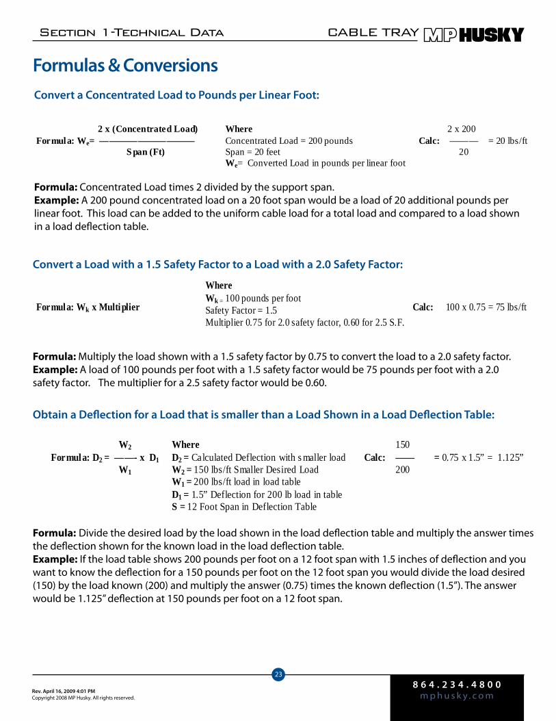
Convert a Concentrated Load to Pounds per Linear Foot:
Formula: Concentrated Load times 2 divided by the support span.Example: A 200 pound concentrated load on a 20 foot span would be a load of 20 additional pounds per linear foot. This load can be added to the uniform cable load for a total load and compared to a load shown in a load deflection table.
Convert a Load with a 1.5 Safety Factor to a Load with a 2.0 Safety Factor:
Formula: Multiply the load shown with a 1.5 safety factor by 0.75 to convert the load to a 2.0 safety factor.Example: A load of 100 pounds per foot with a 1.5 safety factor would be 75 pounds per foot with a 2.0 safety factor. The multiplier for a 2.5 safety factor would be 0.60.
Obtain a Deflection for a Load that is smaller than a Load Shown in a Load Deflection Table:
Formula: Divide the desired load by the load shown in the load deflection table and multiply the answer times the deflection shown for the known load in the load deflection table.Example: If the load table shows 200 pounds per foot on a 12 foot span with 1.5 inches of deflection and you want to know the deflection for a 150 pounds per foot on the 12 foot span you would divide the load desired (150) by the load known (200) and multiply the answer (0.75) times the known deflection (1.5”). The answer would be 1.125” deflection at 150 pounds per foot on a 12 foot span.
Where Concentrated Load = 200 pounds Span = 20 feet We= Converted Load in pounds per linear foot
2 x 200 Calc: ——— = 20 lbs/ft 20
2 x (Concentrated Load) Formula: We= —————————— S pan (Ft)
Formula: Wk x Multiplier
Calc: 100 x 0.75 = 75 lbs/ft
Where Wk = 100 pounds per foot Safety Factor = 1.5 Multiplier 0.75 for 2.0 safety factor, 0.60 for 2.5 S.F.
W2 Formula: D2 = ——- x D1 W1
150 Calc: —— = 0.75 x 1.5” = 1.125” 200
Where D2 = Calculated Deflection with s maller load W2 = 150 lbs/ft Smaller Desired Load W1 = 200 lbs/ft load in load table D1 = 1.5” Deflection for 200 lb load in table S = 12 Foot Span in Deflection Table
Formulas & Conversions
8 6 4 . 2 3 4 . 4 8 0 0m p h u s k y . c o m
Rev. April 16, 2009 4:01 PMCopyright 2008 MP Husky. All rights reserved.
Cable TRAY Section 1-Technical Data
24
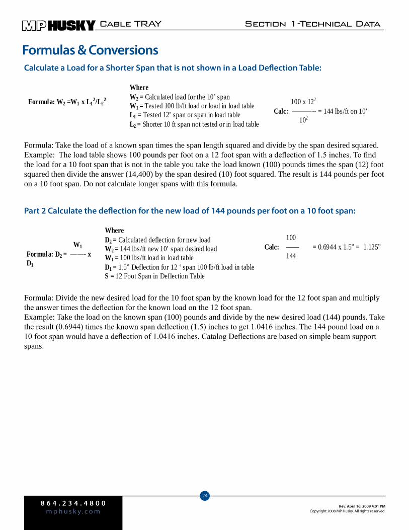
Where W2 = Calcu lated load for the 10’ span W1 = Tested 100 lb/ft load or load in load table L1 = Tested 12’ span or span in load table L2 = Shorter 10 ft span not tested or in load table
100 x 122
Calc: ———-- = 144 lbs/ft on 10’ 102
Formula: W2 =W1 x L12/L2
2
W1 Formula: D2 = ——- x D1
Where D2 = Calculated deflection for new load W2 = 144 lbs/ft new 10’ span desired load W1 = 100 lbs/ft load in load table D1 = 1.5” Deflection for 12 ‘ span 100 lb/ft load in table S = 12 Foot Span in Deflection Table
100 Calc: —— = 0.6944 x 1.5” = 1.125” 144
Calculate a Load for a Shorter Span that is not shown in a Load Deflection Table:
Formula: Take the load of a known span times the span length squared and divide by the span desired squared.Example: The load table shows 100 pounds per foot on a 12 foot span with a deflection of 1.5 inches. To find the load for a 10 foot span that is not in the table you take the load known (100) pounds times the span (12) foot squared then divide the answer (14,400) by the span desired (10) foot squared. The result is 144 pounds per foot on a 10 foot span. Do not calculate longer spans with this formula.
Part 2 Calculate the deflection for the new load of 144 pounds per foot on a 10 foot span:
Formula: Divide the new desired load for the 10 foot span by the known load for the 12 foot span and multiply the answer times the deflection for the known load on the 12 foot span.Example: Take the load on the known span (100) pounds and divide by the new desired load (144) pounds. Take the result (0.6944) times the known span deflection (1.5) inches to get 1.0416 inches. The 144 pound load on a 10 foot span would have a deflection of 1.0416 inches. Catalog Deflections are based on simple beam support spans.
Formulas & Conversions
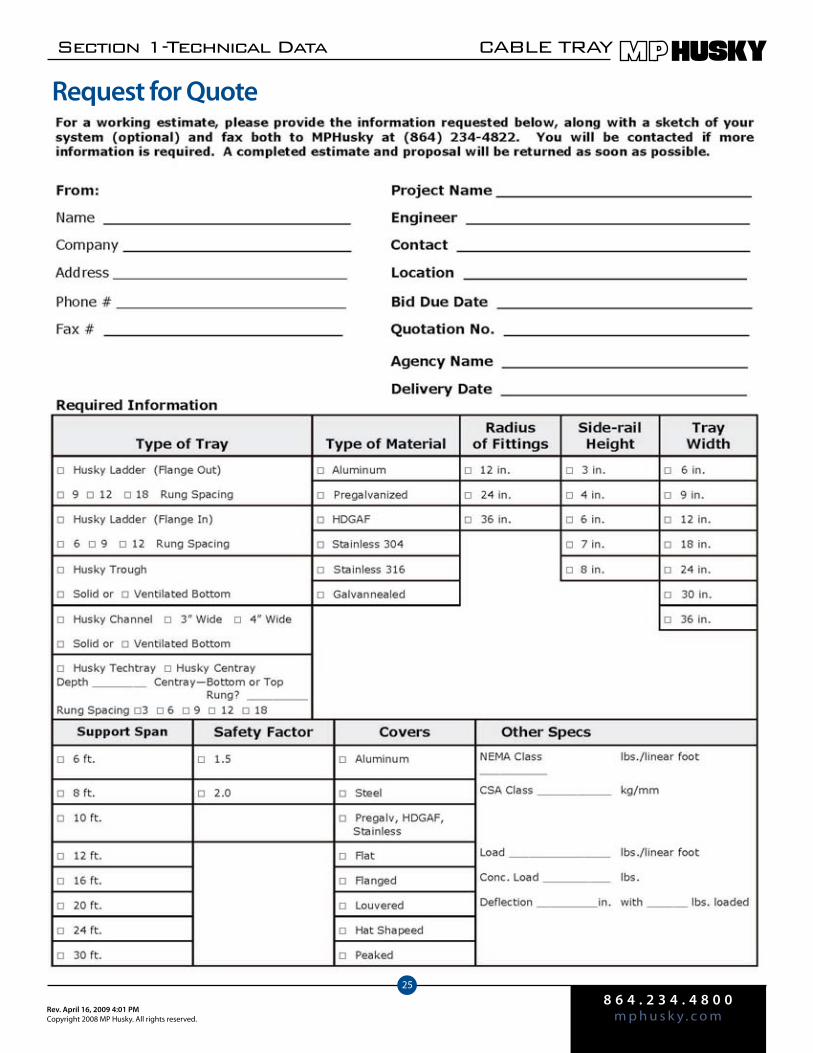
8 6 4 . 2 3 4 . 4 8 0 0m p h u s k y . c o mRev. April 16, 2009 4:01 PM
Copyright 2008 MP Husky. All rights reserved.
Section 1-Technical Data CABLE TRAY
25
Request for Quote

2.1
Husky Ladder Flange Out
In Aluminum, Steel and Stainless Steel
Selection Tables Pg. 2.2Numbering System Pg. 2.3 Loading Tables Pgs. 2.4—2.8
The upper flange may have an extruded lip, a
bent lip, or no lip at all depending on the style.

acc
eSSo
rieS
8 6 4 . 2 3 4 . 4 8 0 0m p h u s k y . c o m
Rev. April 17, 2009 11:14 AMcopyright 2008 MP Husky. all rights reserved.
CABLE TRAY
2
SteelAluminum
Husky Ladder has the exclusive Thru-Weld construction—this completely welds rungs to the outside of the rails for optimum structural integrity and reduced side rail rotation.
NEMAClass Load
Sup-portSpan
SiderailHeight (in.)
LoadDepth
Top FlangeWidth
PrefixSiderailHeight(in.)
LoadDepth
Top FlangeWidth
Prefix
8A 50lbs/ft 8ft 4.506.00
3.505.00
.75
.75A( )BAA( )PB
4.006.00
3.005.00
.75
.75S( )BS( )P
8B 75lbs/ft 8ft 4.506.00
3.505.00
.75
.75A( )BAA( )PB
4.006.00
3.005.00
.75
.75S( )BS( )P
8C 100lbs/ft 8ft 4.506.00
3.505.00
.75
.75A( )BAA( )PB
4.006.00
3.005.00
.75
.75S( )BS( )P
12A 50lbs/ft 12ft 4.506.00
3.505.00
.75
.75A( )BAA( )PB
4.006.00
3.005.00
.75
.75S( )BS( )P
12B 75lbs/ft 12ft 4.506.00
3.505.00
.75
.75A( )BBA( )PB
4.006.00
3.005.00
.75
.75S( )BS( )P
12C 100lbs/ft 12ft 4.506.00
3.505.00
1.501.75
A( )CAA( )EA
4.506.00
3.505.00
.75
.75S( )BCS( )PD
16A 50lbs/ft 16ft 4.506.00
3.505.00
1.501.75
A( )CAA( )EA
4.506.25
3.505.25
1.751.75
S( )CDS( )EB
16B 75lbs/ft 16ft 4.506.00
3.505.00
1.501.75
A( )CAA( )EA
4.506.25
3.505.25
1.751.75
S( )CDS( )EB
16C 100lbs/ft 16ft 6.00 5.00 1.75 A( )E 6.25 5.25 1.75 S( )EB
20A 50lbs/ft 20ft 4.506.00
3.505.00
1.501.75
A( )CAA( )EA
4.506.25
3.505.25
1.751.75
S( )CDS( )EB
20B 75lbs/ft 20ft 6.007.00
5.006.00
1.751.75
A( )EA( )E7
6.25 5.25 1.75 S( )EB
20C 100lbs/ft 20ft 6.007.00
5.006.00
1.751.75
A( )E1A( )E71
6.256.25
5.255.25
1.751.75
S( )ECS( )EC
20C+ 100+lbs/ft 20ft 6.25 5.25 1.75 S( )ED
24C 100lbs/ft 24ft 6.25 5.25 1.75 S( )ED
SELECTION TABLES
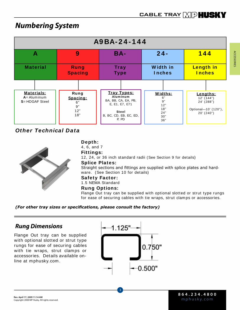
acceSSo
rieS
8 6 4 . 2 3 4 . 4 8 0 0m p h u s k y . c o mRev. April 17, 2009 11:14 AM
copyright 2008 MP Husky. all rights reserved.
CABLE TRAY
3
Numbering System
Other Technical Data
Depth:4, 6, and 7Fittings:12, 24, or 36 inch standard radii (See Section 9 for details)Splice Plates:Straight sections and fittings are supplied with splice plates and hard-ware. (See Section 10 for details)Safety Factor:1.5 NEMA StandardRung Options:Flange Out tray can be supplied with optional slotted or strut type rungs for ease of securing cables with tie wraps, strut clamps or accessories.
(For other tray sizes or specifications, please consult the factory)
Rung Dimensions
A9BA-24-144
Materials:A=Aluminum
S=HDGAF Steel
Tray Types:Aluminum
BA, BB, CA, EA, PB, E, E1, E7, E71
SteelB, BC, CD, EB, EC, ED,
P, PD
Widths:6”9”12”18”24”30”36”
Lengths:12’ (144”)24’ (288”)
Optional—10’ (120”), 20’ (240”)
A 9 BA- 24- 144
Material Rung Spacing
Tray Type
Width in Inches
Length in Inches
RungSpacing:
6”9”12”18”
Flange Out tray can be supplied with optional slotted or strut type rungs for ease of securing cables with tie wraps, strut clamps or accessories. Details available on-line at mphusky.com.

acc
eSSo
rieS
8 6 4 . 2 3 4 . 4 8 0 0m p h u s k y . c o m
Rev. April 17, 2009 11:14 AMcopyright 2008 MP Husky. all rights reserved.
CABLE TRAY
4
Span (ft.) 4 6 8 10 12
Width (in.) Load Defl Load Defl Load Defl Load Defl Load Defl
6 540 0.15 240 0.34 135 0.61 86 0.96 60 1.38
9 540 0.15 240 0.34 135 0.61 86 0.96 60 1.38
12 497* 0.14 240 0.34 135 0.61 86 0.96 60 1.38
18 331* 0.09 240 0.34 135 0.61 86 0.96 60 1.38
24 248* 0.07 240 0.34 135 0.61 86 0.96 60 1.38
30 199* 0.06 199* 0.28 135 0.61 86 0.96 60 1.38
36 166* 0.05 166* 0.24 135 0.61 86 0.96 60 1.38
Span (ft.) 4 6 8 10 12
Width (in.) Load Defl Load Defl Load Defl Load Defl Load Defl
6 675 0.14 300 0.32 169 0.57 108 0.89 75 1.28
9 662* 0.14 300 0.32 169 0.57 108 0.89 75 1.28
12 497* 0.10 300 0.32 169 0.57 108 0.89 75 1.28
18 331* 0.07 300 0.32 169 0.57 108 0.89 75 1.28
24 248* 0.05 248* 0.27 169 0.57 108 0.89 75 1.28
30 199* 0.04 199* 0.21 169 0.57 108 0.89 75 1.28
36 166* 0.03 166* 0.18 169 0.57 108 0.89 75 1.28
Span (ft.) 12 14 16 18 20
Width (in.) Load Defl Load Defl Load Defl Load Defl Load Defl
6 139 1.63 102 2.22 78 2.90 62 3.67 50 4.53
9 139 1.63 102 2.22 78 2.90 62 3.67 50 4.53
12 139 1.63 102 2.22 78 2.90 62 3.67 50 4.53
18 139 1.63 102 2.22 78 2.90 62 3.67 50 4.53
24 139 1.63 102 2.22 78 2.90 62 3.67 50 4.53
30 139 1.63 102 2.22 78 2.90 62 3.67 50 4.53
36 139 1.63 102 2.22 78 2.90 62 3.67 50 4.53
A CA( )
NEMA 20A, 16B, 12C/CSA D
Use ALCA fittings
NEMA 12B/CSA C
Use ALBB fittingsA BB( )
A BA( ) Use ALBA fittings
NEMA 12A
Loading Tables for Aluminum Ladder
Span (ft.) 4 6 8 10 12
Width (in.) Load Defl Load Defl Load Defl Load Defl Load Defl
6 675 0.06 300 0.15 169 0.27 108 0.43 75 0.62
9 662* 0.06 300 0.15 169 0.27 108 0.43 75 0.62
12 497* 0.04 300 0.15 169 0.27 108 0.43 75 0.62
18 331* 0.03 300 0.15 169 0.27 108 0.43 75 0.62
24 248* 0.02 248* 0.12 169 0.27 108 0.43 75 0.62
30 199* 0.02 199* 0.10 169 0.27 108 0.43 75 0.62
36 166* 0.02 166* 0.08 166* 0.27 108 0.43 75 0.62
Use ALPB fittings
NEMA 12B
A PB( )
Span (ft.) 12 14 16 18 20
Width (in.) Load Defl Load Defl Load Defl Load Defl Load Defl
6 144 0.87 106 1.19 81 1.56 64 1.97 52 2.43
9 144 0.87 106 1.19 81 1.56 64 1.97 52 2.43
12 144 0.87 106 1.19 81 1.56 64 1.97 52 2.43
18 144 0.87 106 1.19 81 1.56 64 1.97 52 2.43
24 144 0.87 106 1.19 81 1.56 64 1.97 52 2.43
30 144 0.87 106 1.19 81 1.56 64 1.97 52 2.43
36 144 0.87 106 1.19 81 1.56 64 1.97 52 2.43
NEMA 20A, 16B, 12C/CSA D
A ( ) EA Use ALE fittings
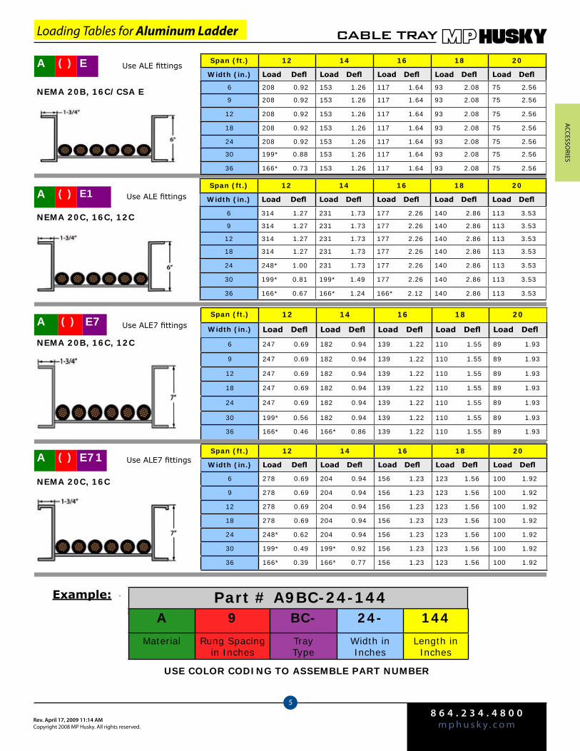
acceSSo
rieS
8 6 4 . 2 3 4 . 4 8 0 0m p h u s k y . c o mRev. April 17, 2009 11:14 AM
copyright 2008 MP Husky. all rights reserved.
CABLE TRAY
5
Loading Tables for Aluminum Ladder
Use ALE fittingsA ( ) E
NEMA 20B, 16C/CSA E
Span (ft.) 12 14 16 18 20
Width (in.) Load Defl Load Defl Load Defl Load Defl Load Defl
6 208 0.92 153 1.26 117 1.64 93 2.08 75 2.56
9 208 0.92 153 1.26 117 1.64 93 2.08 75 2.56
12 208 0.92 153 1.26 117 1.64 93 2.08 75 2.56
18 208 0.92 153 1.26 117 1.64 93 2.08 75 2.56
24 208 0.92 153 1.26 117 1.64 93 2.08 75 2.56
30 199* 0.88 153 1.26 117 1.64 93 2.08 75 2.56
36 166* 0.73 153 1.26 117 1.64 93 2.08 75 2.56
A ( ) E1 Use ALE fittings
NEMA 20C, 16C, 12C
Span (ft.) 12 14 16 18 20
Width (in.) Load Defl Load Defl Load Defl Load Defl Load Defl
6 314 1.27 231 1.73 177 2.26 140 2.86 113 3.53
9 314 1.27 231 1.73 177 2.26 140 2.86 113 3.53
12 314 1.27 231 1.73 177 2.26 140 2.86 113 3.53
18 314 1.27 231 1.73 177 2.26 140 2.86 113 3.53
24 248* 1.00 231 1.73 177 2.26 140 2.86 113 3.53
30 199* 0.81 199* 1.49 177 2.26 140 2.86 113 3.53
36 166* 0.67 166* 1.24 166* 2.12 140 2.86 113 3.53
Use ALE7 fittingsA ( ) E7
NEMA 20B, 16C, 12C
Span (ft.) 12 14 16 18 20
Width (in.) Load Defl Load Defl Load Defl Load Defl Load Defl
6 247 0.69 182 0.94 139 1.22 110 1.55 89 1.93
9 247 0.69 182 0.94 139 1.22 110 1.55 89 1.93
12 247 0.69 182 0.94 139 1.22 110 1.55 89 1.93
18 247 0.69 182 0.94 139 1.22 110 1.55 89 1.93
24 247 0.69 182 0.94 139 1.22 110 1.55 89 1.93
30 199* 0.56 182 0.94 139 1.22 110 1.55 89 1.93
36 166* 0.46 166* 0.86 139 1.22 110 1.55 89 1.93
Span (ft.) 12 14 16 18 20
Width (in.) Load Defl Load Defl Load Defl Load Defl Load Defl
6 278 0.69 204 0.94 156 1.23 123 1.56 100 1.92
9 278 0.69 204 0.94 156 1.23 123 1.56 100 1.92
12 278 0.69 204 0.94 156 1.23 123 1.56 100 1.92
18 278 0.69 204 0.94 156 1.23 123 1.56 100 1.92
24 248* 0.62 204 0.94 156 1.23 123 1.56 100 1.92
30 199* 0.49 199* 0.92 156 1.23 123 1.56 100 1.92
36 166* 0.39 166* 0.77 156 1.23 123 1.56 100 1.92
A ( ) E71 Use ALE7 fittings
NEMA 20C, 16C
Part # A9BC-24-144A 9 BC- 24- 144
Material Rung Spacing in Inches
Tray Type
Width in Inches
Length in Inches
USE COLOR CODING TO ASSEMBLE PART NUMBER
Example:
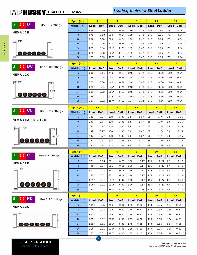
acc
eSSo
rieS
8 6 4 . 2 3 4 . 4 8 0 0m p h u s k y . c o m
Rev. April 17, 2009 11:14 AMcopyright 2008 MP Husky. all rights reserved.
CABLE TRAY
6
Span (ft.) 4 6 8 10 12
Width (in.) Load Defl Load Defl Load Defl Load Defl Load Defl
6 675 0.10 300 0.24 169 0.42 108 0.65 75 0.94
9 675 0.10 300 0.24 169 0.42 108 0.65 75 0.94
12 562* 0.08 300 0.24 169 0.42 108 0.65 75 0.94
18 375* 0.06 300 0.24 169 0.42 108 0.65 75 0.94
24 281* 0.04 281* 0.23 169 0.42 108 0.65 75 0.94
30 225* 0.03 225* 0.18 169 0.42 108 0.65 75 0.94
36 187* 0.03 187* 0.15 169 0.42 108 0.65 75 0.94
Span (ft.) 4 6 8 10 12
Width (in.) Load Defl Load Defl Load Defl Load Defl Load Defl
6 990 0.11 440 0.24 248 0.42 158 0.66 110 0.94
9 749* 0.08 440 0.24 248 0.42 158 0.66 110 0.94
12 562* 0.06 440 0.24 248 0.42 158 0.66 110 0.94
18 375* 0.04 375* 0.21 248 0.42 158 0.66 110 0.94
24 281* 0.03 281* 0.15 248 0.42 158 0.66 110 0.94
30 225* 0.03 225* 0.12 225* 0.38 158 0.66 110 0.94
36 187* 0.02 187* 0.10 187* 0.32 158 0.66 110 0.94
Span (ft.) 12 14 16 18 20
Width (in.) Load Defl Load Defl Load Defl Load Defl Load Defl
6 147 0.77 108 1.05 83 1.37 65 1.74 53 2.15
9 147 0.77 108 1.05 83 1.37 65 1.74 53 2.15
12 147 0.77 108 1.05 83 1.37 65 1.74 53 2.15
18 147 0.77 108 1.05 83 1.37 65 1.74 53 2.15
24 147 0.77 108 1.05 83 1.37 65 1.74 53 2.15
30 147 0.77 108 1.05 83 1.37 65 1.74 53 2.15
36 147 0.77 108 1.05 83 1.37 65 1.74 53 2.15
Span (ft.) 4 6 8 10 12
Width (in.) Load Defl Load Defl Load Defl Load Defl Load Defl
6 791 0.04 351 0.09 196 0.17 125 0.27 87 0.39
9 749* 0.04 351 0.09 196 0.17 125 0.27 87 0.39
12 562* 0.03 351 0.09 196 0.17 125 0.27 87 0.39
18 375* 0.02 351 0.09 196 0.17 125 0.27 87 0.39
24 281* 0.01 281* 0.07 196 0.17 125 0.27 87 0.39
30 225* 0.01 225* 0.06 196 0.17 125 0.27 87 0.39
36 187* 0.01 187* 0.05 187* 0.16 125 0.27 87 0.39
Span (ft.) 4 6 8 10 12
Width (in.) Load Defl Load Defl Load Defl Load Defl Load Defl
6 1116 0.05 496 0.12 279 0.22 179 0.35 124 0.51
9 749* 0.03 496 0.12 279 0.22 179 0.35 124 0.51
12 562* 0.03 496 0.12 279 0.22 179 0.35 124 0.51
18 375* 0.02 375* 0.09 279 0.22 179 0.35 124 0.51
24 281* 0.01 281* 0.07 279 0.22 179 0.35 124 0.51
30 225* 0.01 225* 0.05 225* 0.18 179 0.35 124 0.51
36 187* 0.01 187* 0.05 187* 0.15 179 0.35 124 0.51
NEMA 12B
Use SLB fittingsS B( )
S BC( )
S CD( )
S P( )
S PD( )
Use SLBC fittings
NEMA 12C
NEMA 20A, 16B, 12C
Use SLCD fittings
Use SLP fittings
NEMA 12B
NEMA 12C
Use SLPD fittings
Loading Tables for Steel Ladder
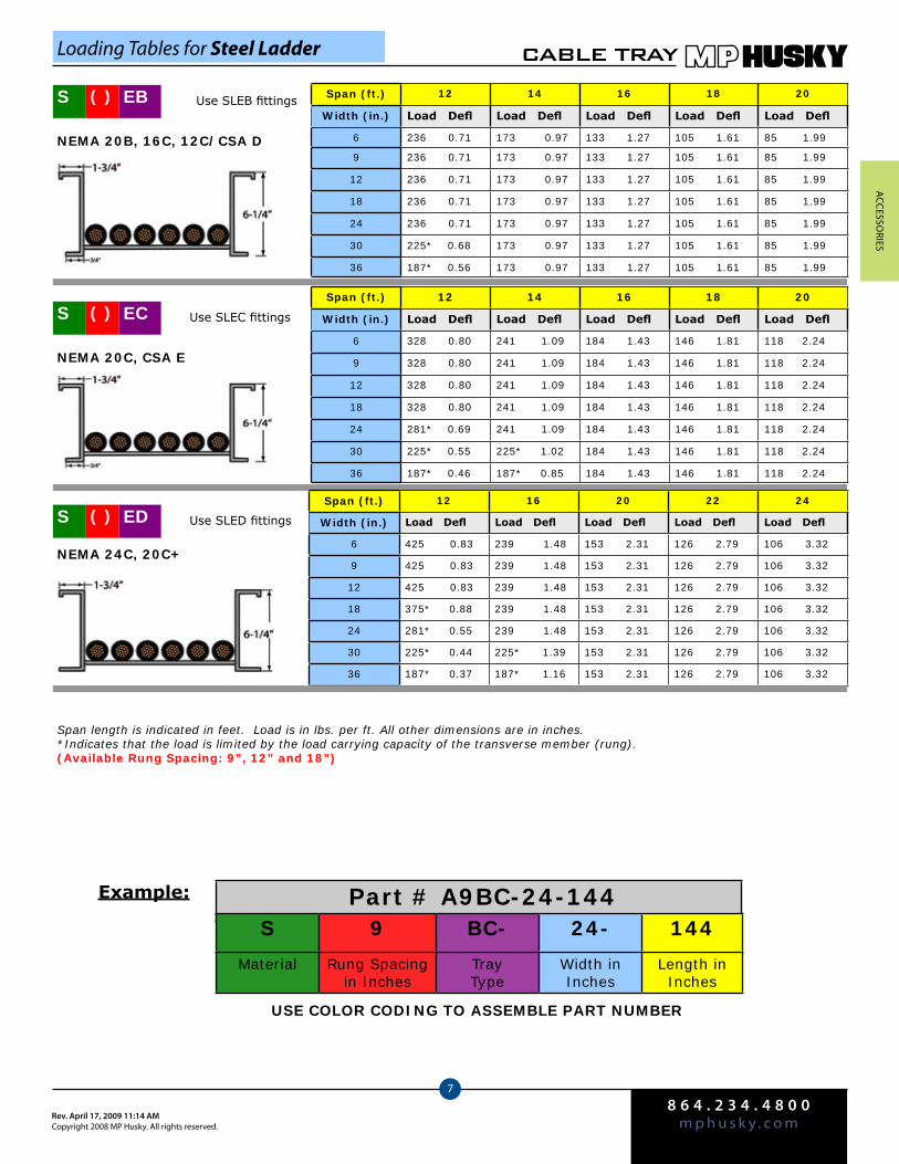
acceSSo
rieS
8 6 4 . 2 3 4 . 4 8 0 0m p h u s k y . c o mRev. April 17, 2009 11:14 AM
copyright 2008 MP Husky. all rights reserved.
CABLE TRAY
7
Span (ft.) 12 14 16 18 20
Width (in.) Load Defl Load Defl Load Defl Load Defl Load Defl
6 236 0.71 173 0.97 133 1.27 105 1.61 85 1.99
9 236 0.71 173 0.97 133 1.27 105 1.61 85 1.99
12 236 0.71 173 0.97 133 1.27 105 1.61 85 1.99
18 236 0.71 173 0.97 133 1.27 105 1.61 85 1.99
24 236 0.71 173 0.97 133 1.27 105 1.61 85 1.99
30 225* 0.68 173 0.97 133 1.27 105 1.61 85 1.99
36 187* 0.56 173 0.97 133 1.27 105 1.61 85 1.99
Span (ft.) 12 14 16 18 20
Width (in.) Load Defl Load Defl Load Defl Load Defl Load Defl
6 328 0.80 241 1.09 184 1.43 146 1.81 118 2.24
9 328 0.80 241 1.09 184 1.43 146 1.81 118 2.24
12 328 0.80 241 1.09 184 1.43 146 1.81 118 2.24
18 328 0.80 241 1.09 184 1.43 146 1.81 118 2.24
24 281* 0.69 241 1.09 184 1.43 146 1.81 118 2.24
30 225* 0.55 225* 1.02 184 1.43 146 1.81 118 2.24
36 187* 0.46 187* 0.85 184 1.43 146 1.81 118 2.24
Span (ft.) 12 16 20 22 24
Width (in.) Load Defl Load Defl Load Defl Load Defl Load Defl
6 425 0.83 239 1.48 153 2.31 126 2.79 106 3.32
9 425 0.83 239 1.48 153 2.31 126 2.79 106 3.32
12 425 0.83 239 1.48 153 2.31 126 2.79 106 3.32
18 375* 0.88 239 1.48 153 2.31 126 2.79 106 3.32
24 281* 0.55 239 1.48 153 2.31 126 2.79 106 3.32
30 225* 0.44 225* 1.39 153 2.31 126 2.79 106 3.32
36 187* 0.37 187* 1.16 153 2.31 126 2.79 106 3.32
S ED( ) Use SLED fittings
NEMA 24C, 20C+
S EC( ) Use SLEC fittings
NEMA 20C, CSA E
S EB( ) Use SLEB fittings
NEMA 20B, 16C, 12C/CSA D
Span length is indicated in feet. Load is in lbs. per ft. All other dimensions are in inches.*Indicates that the load is limited by the load carrying capacity of the transverse member (rung).(Available Rung Spacing: 9”, 12” and 18”)
Loading Tables for Steel Ladder
Part # A9BC-24-144S 9 BC- 24- 144
Material Rung Spacing in Inches
Tray Type
Width in Inches
Length in Inches
USE COLOR CODING TO ASSEMBLE PART NUMBER
Example:

Husky Ladder - Flange InIn Steel & Aluminum
Selection Tables Pg. 3.2Numbering System Pg. 3.3Loading Tables Pgs. 3.4—3.8
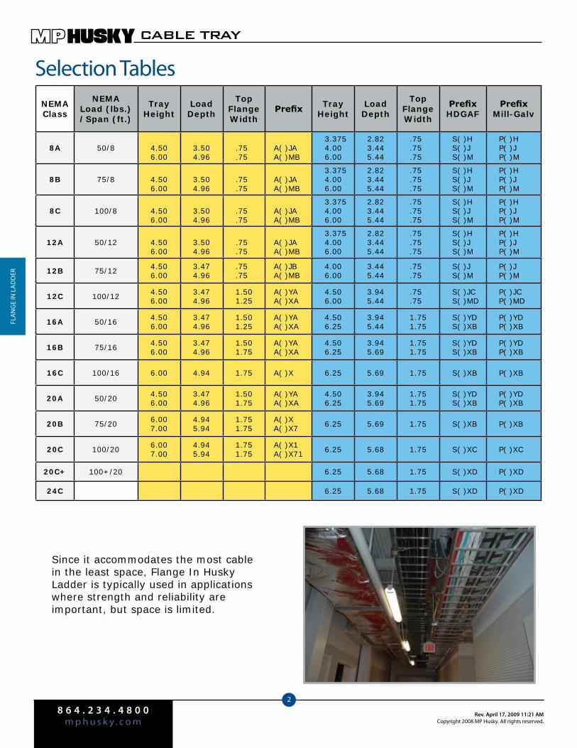
8 6 4 . 2 3 4 . 4 8 0 0m p h u s k y . c o m
Rev. April 17, 2009 11:21 AMCopyright 2008 MP Husky. All rights reserved.
CABLE TRAY
2
fLA
Ng
e iN
LA
dd
er
Selection Tables
Since it accommodates the most cable in the least space, Flange In Husky Ladder is typically used in applications where strength and reliability are important, but space is limited.
NEMAClass
NEMALoad (lbs.)/Span (ft.)
TrayHeight
LoadDepth
Top FlangeWidth
Prefix TrayHeight
LoadDepth
Top FlangeWidth
PrefixHDGAF
PrefixMill-Galv
8A 50/8 4.506.00
3.504.96
.75
.75A( )JAA( )MB
3.3754.006.00
2.823.445.44
.75
.75
.75
S( )HS( )JS( )M
P( )HP( )JP( )M
8B 75/8 4.506.00
3.504.96
.75
.75A( )JAA( )MB
3.3754.006.00
2.823.445.44
.75
.75
.75
S( )HS( )JS( )M
P( )HP( )JP( )M
8C 100/8 4.506.00
3.504.96
.75
.75A( )JAA( )MB
3.3754.006.00
2.823.445.44
.75
.75
.75
S( )HS( )JS( )M
P( )HP( )JP( )M
12A 50/12 4.506.00
3.504.96
.75
.75A( )JAA( )MB
3.3754.006.00
2.823.445.44
.75
.75
.75
S( )HS( )JS( )M
P( )HP( )JP( )M
12B 75/12 4.506.00
3.474.96
.75
.75A( )JBA( )MB
4.006.00
3.445.44
.75
.75S( )JS( )M
P( )JP( )M
12C 100/12 4.506.00
3.474.96
1.501.25
A( )YAA( )XA
4.506.00
3.945.44
.75
.75S( )JCS( )MD
P( )JCP( )MD
16A 50/16 4.506.00
3.474.96
1.501.25
A( )YAA( )XA
4.506.25
3.945.44
1.751.75
S( )YDS( )XB
P( )YDP( )XB
16B 75/16 4.506.00
3.474.96
1.501.75
A( )YAA( )XA
4.506.25
3.945.69
1.751.75
S( )YDS( )XB
P( )YDP( )XB
16C 100/16 6.00 4.94 1.75 A( )X 6.25 5.69 1.75 S( )XB P( )XB
20A 50/20 4.506.00
3.474.96
1.501.75
A( )YAA( )XA
4.506.25
3.945.69
1.751.75
S( )YDS( )XB
P( )YDP( )XB
20B 75/20 6.007.00
4.945.94
1.751.75
A( )XA( )X7 6.25 5.69 1.75 S( )XB P( )XB
20C 100/20 6.007.00
4.945.94
1.751.75
A( )X1A( )X71 6.25 5.68 1.75 S( )XC P( )XC
20C+ 100+/20 6.25 5.68 1.75 S( )XD P( )XD
24C 6.25 5.68 1.75 S( )XD P( )XD
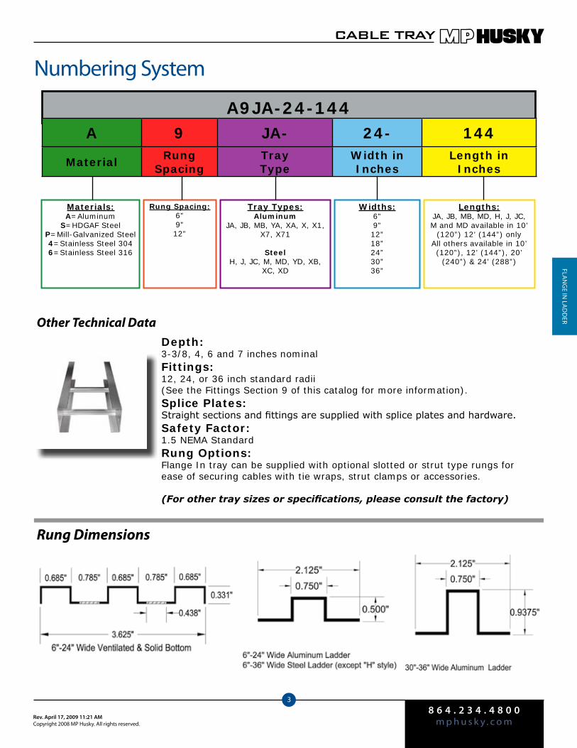
8 6 4 . 2 3 4 . 4 8 0 0m p h u s k y . c o mRev. April 17, 2009 11:21 AM
Copyright 2008 MP Husky. All rights reserved.
CABLE TRAY
3
fLAN
ge iN
LAd
der
Numbering System
A9JA-24-144
Materials:A=Aluminum
S=HDGAF SteelP=Mill-Galvanized Steel4=Stainless Steel 3046=Stainless Steel 316
Rung Spacing:6”9”12”
Tray Types:Aluminum
JA, JB, MB, YA, XA, X, X1, X7, X71
SteelH, J, JC, M, MD, YD, XB,
XC, XD
Widths:6”9”12”18”24”30”36”
Lengths:JA, JB, MB, MD, H, J, JC, M and MD available in 10’
(120”) 12’ (144”) onlyAll others available in 10’ (120”), 12’ (144”), 20’
(240”) & 24’ (288”)
Rung Dimensions
A 9 JA- 24- 144
Material Rung Spacing
Tray Type
Width in Inches
Length in Inches
Other Technical DataDepth:3-3/8, 4, 6 and 7 inches nominalFittings:12, 24, or 36 inch standard radii (See the Fittings Section 9 of this catalog for more information).Splice Plates:Straight sections and fittings are supplied with splice plates and hardware.Safety Factor:1.5 NEMA StandardRung Options:Flange In tray can be supplied with optional slotted or strut type rungs for ease of securing cables with tie wraps, strut clamps or accessories.
(For other tray sizes or specifications, please consult the factory)

8 6 4 . 2 3 4 . 4 8 0 0m p h u s k y . c o m
Rev. April 17, 2009 11:21 AMCopyright 2008 MP Husky. All rights reserved.
CABLE TRAY
4
fLA
Ng
e iN
LA
dd
er
Loading Tables for Aluminum Ladder
Span (ft.) 4 6 8 10 12
Width (in.) Load Defl Load Defl Load Defl Load Defl Load Defl
6 540 0.15 240 0.34 135 0.61 86 0.96 60 1.38
9 540 0.15 240 0.34 135 0.61 86 0.96 60 1.38
12 405* 0.11 240 0.34 135 0.61 86 0.96 60 1.38
18 270* 0.08 240 0.34 135 0.61 86 0.96 60 1.38
24 202* 0.06 202* 0.29 135 0.61 86 0.96 60 1.38
30 376* 0.10 240 0.34 135 0.61 86 0.96 60 1.38
36 313* 0.09 240 0.34 135 0.61 86 0.96 60 1.38
Span (ft.) 4 6 8 10 12
Width (in.) Load Defl Load Defl Load Defl Load Defl Load Defl
6 675 0.14 300 0.32 169 0.57 108 0.89 75 1.28
9 540* 0.11 300 0.32 169 0.57 108 0.89 75 1.28
12 405* 0.08 300 0.32 169 0.57 108 0.89 75 1.28
18 270* 0.06 270* 0.29 169 0.57 108 0.89 75 1.28
24 202* 0.04 202* 0.22 169 0.57 108 0.89 75 1.28
30 376* 0.08 300 0.32 169 0.57 108 0.89 75 1.28
36 313* 0.07 300 0.32 169 0.57 108 0.89 75 1.28
Span (ft.) 4 6 8 10 12
Width (in.) Load Defl Load Defl Load Defl Load Defl Load Defl
6 675 0.06 300 0.15 169 0.27 108 0.43 75 0.62
9 540* 0.05 300 0.15 169 0.27 108 0.43 75 0.62
12 405* 0.04 300 0.15 169 0.27 108 0.43 75 0.62
18 270* 0.02 270* 0.14 169 0.27 108 0.43 75 0.62
24 202* 0.02 202* 0.10 169 0.27 108 0.43 75 0.62
30 376* 0.03 300 0.15 169 0.27 108 0.43 75 0.62
36 313* 0.03 300 0.15 169 0.27 108 0.43 75 0.62
Span (ft.) 12 14 16 18 20
Width (in.) Load Defl Load Defl Load Defl Load Defl Load Defl
9 144 0.87 106 1.19 81 1.56 64 1.97 52 2.43
12 144 0.87 106 1.19 81 1.56 64 1.97 52 2.43
18 144 0.87 106 1.19 81 1.56 64 1.97 52 2.43
24 144 0.87 106 1.19 81 1.56 64 1.97 52 2.43
30 144 0.87 106 1.19 81 1.56 64 1.97 52 2.43
36 144 0.87 106 1.19 81 1.56 64 1.97 52 2.43
Use ALX fittings
NEMA 20A, 16B, 12C
A XA( )
Use ALMB fittings
NEMA 12B
A MB( )
Use ALYA fittingsA YA( )
Use ALJB fittings
NEMA 12B/CSA C
A JB( )
Use ALJA fittings
NEMA 12A
A JA( )
Span (ft.) 12 14 16 18 20
Width (in.) Load Defl Load Defl Load Defl Load Defl Load Defl
6 139 1.63 102 2.22 78 2.90 62 3.67 50 4.53
9 139 1.63 102 2.22 78 2.90 62 3.67 50 4.53
12 139 1.63 102 2.22 78 2.90 62 3.67 50 4.53
18 139 1.63 102 2.22 78 2.90 62 3.67 50 4.53
24 139 1.63 102 2.22 78 2.90 62 3.67 50 4.53
30 139 1.63 102 2.22 78 2.90 62 3.67 50 4.53
36 139 1.63 102 2.22 78 2.90 62 3.67 50 4.53
NEMA 20A, 16B, 12C/CSA D

8 6 4 . 2 3 4 . 4 8 0 0m p h u s k y . c o mRev. April 17, 2009 11:21 AM
Copyright 2008 MP Husky. All rights reserved.
CABLE TRAY
5
fLAN
ge iN
LAd
der
Loading Tables for Aluminum Ladder
Span (ft.) 12 14 16 18 20
Width (in.) Load Defl Load Defl Load Defl Load Defl Load Defl
9 208 0.92 153 1.26 117 1.64 93 2.08 75 2.56
12 208 0.92 153 1.26 117 1.64 93 2.08 75 2.56
18 208 0.92 153 1.26 117 1.64 93 2.08 75 2.56
24 202* 0.89 153 1.26 117 1.64 93 2.08 75 2.56
30 208 0.92 153 1.26 117 1.64 93 2.08 75 2.56
36 208 0.92 153 1.26 117 1.64 93 2.08 75 2.56
Span (ft.) 12 14 16 18 20
Width (in.) Load Defl Load Defl Load Defl Load Defl Load Defl
9 314 1.27 231 1.73 177 2.26 140 2.86 113 3.53
12 314 1.27 231 1.73 177 2.26 140 2.86 113 3.53
18 270* 1.09 231 1.73 177 2.26 140 2.52 100 3.13
24 202* 0.82 202* 1.51 177 2.26 140 2.52 100 3.13
30 314 1.12 231 1.73 177 2.26 140 2.52 100 3.13
36 313* 1.27 231 1.73 177 2.26 140 2.52 100 3.13
Use ALX fittings
NEMA 20C, 16C
A X1( )
Use ALX fittings
NEMA 20B, 16C
A X( )
Use ALX7 fittings
NEMA 20B, 16C, 12C
A X7( )Span (ft.) 12 14 16 18 20
Width (in.) Load Defl Load Defl Load Defl Load Defl Load Defl
9 247 0.69 182 0.94 139 1.22 110 1.55 89 1.93
12 247 0.69 182 0.94 139 1.22 110 1.55 89 1.93
18 247 0.69 182 0.94 139 1.22 110 1.55 89 1.93
24 202* 0.56 182 0.94 139 1.22 110 1.55 89 1.93
30 247 0.69 182 0.94 139 1.22 110 1.55 89 1.93
36 247 0.69 182 0.94 139 1.22 110 1.55 89 1.93
Use ALX7 fittings
NEMA 20C, 16C, 12C
A X71( )Span (ft.) 12 14 16 18 20
Width (in.) Load Defl Load Defl Load Defl Load Defl Load Defl
9 278 0.69 204 0.94 156 1.23 123 1.56 100 1.92
12 278 0.69 204 0.94 156 1.23 123 1.56 100 1.92
18 270* 0.67 204 0.94 156 1.23 123 1.56 100 1.92
24 202* 0.50 202* 0.93 156 1.23 123 1.56 100 1.92
30 278 0.69 204 0.94 156 1.23 123 1.56 100 1.92
36 278 0.69 204 0.94 156 1.23 123 1.56 100 1.92
Span length is indicated in feet. All other dimensions are in inches.* Indicates that the load is limited by the load carrying capacity of the transverse member (rung).

8 6 4 . 2 3 4 . 4 8 0 0m p h u s k y . c o m
Rev. April 17, 2009 11:21 AMCopyright 2008 MP Husky. All rights reserved.
CABLE TRAY
6
fLA
Ng
e iN
LA
dd
er
Loading Tables for Steel Ladder
Span (ft.) 4 6 8 10 12
Width (in.) Load Defl Load Defl Load Defl Load Defl Load Defl
6 408* 0.09 280 0.24 157 0.57 101 0.88 70 1.27
9 272* 0.06 272* 0.31 157 0.57 101 0.88 70 1.27
12 204* 0.05 204* 0.23 157 0.57 101 0.88 70 1.27
18 136* 0.03 136* 0.24 136* 0.49 101 0.88 70 1.27
24 102* 0.02 102* 0.12 102* 0.37 101 0.88 70 1.27
**30 261* 0.06 261* 0.22 157 0.57 101 0.88 70 1.27
**36 218* 0.05 218* 0.19 157 0.57 101 0.88 70 1.27
Span (ft.) 4 6 8 10 12
Width (in.) Load Defl Load Defl Load Defl Load Defl Load Defl
**6 675 0.10 300 0.22 169 0.40 108 0.62 75 0.90
**9 675 0.10 300 0.22 169 0.40 108 0.62 75 0.90
**12 653* 0.10 300 0.22 169 0.40 108 0.62 75 0.90
**18 436* 0.07 300 0.22 169 0.40 108 0.62 75 0.90
**24 327* 0.05 300 0.22 169 0.40 108 0.62 75 0.90
**30 261* 0.04 261* 0.19 169 0.40 108 0.62 75 0.90
**36 218* 0.03 218* 0.16 169 0.40 108 0.62 75 0.90
Span (ft.) 4 6 8 10 12
Width (in.) Load Defl Load Defl Load Defl Load Defl Load Defl
**9 871* 0.09 440 0.23 248 0.41 158 0.65 110 0.94
**12 653* 0.07 440 0.23 248 0.41 158 0.65 110 0.94
**18 436* 0.04 436* 0.23 248 0.41 158 0.65 110 0.94
**24 327* 0.03 327* 0.17 248 0.41 158 0.65 110 0.94
**30 261* 0.03 261* 0.14 248 0.41 158 0.65 110 0.94
**36 218* 0.02 218* 0.11 218* 0.36 158 0.65 110 0.94
**6 990 0.10 440 0.23 248 0.41 158 0.65 110 0.94
Use SLH fittings
NEMA 12A
S H( )
P H( )
S J( )
P J( )
Use SLJ fittings
NEMA 12B/CSA C
NEMA 12C
Use SLJC fittingsS JC( )
P JC( )
Hot Dip Galvanized After Fabrication
Mill-GalvanizedUse PLH fittings
Hot Dip Galvanized After Fabrication
Mill-Galvanized
Use PLJ fittings
Hot Dip Galvanized After Fabrication
Mill-Galvanized
Use PLJC fittings
NEMA 20A, 16B, 12C
Span (ft.) 12 14 16 18 20
Width (in.) Load Defl Load Defl Load Defl Load Defl Load Defl
**9 147 0.77 108 1.05 83 1.37 65 1.74 53 2.15
**12 147 0.77 108 1.05 83 1.37 65 1.74 53 2.15
**18 147 0.77 108 1.05 83 1.37 65 1.74 53 2.15
**24 147 0.77 108 1.05 83 1.37 65 1.74 53 2.15
**30 147 0.77 108 1.05 83 1.37 65 1.74 53 2.15
**36 147 0.77 108 1.05 83 1.37 65 1.74 53 2.15
S YD( )
P YD( )
Use SLYD fittings
Hot Dip Galvanized After Fabrication
Mill-Galvanized
Use PLYD fittings
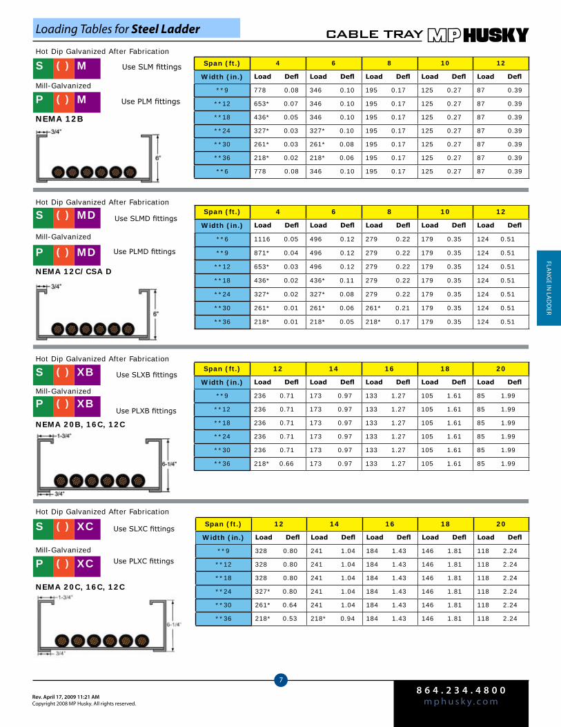
8 6 4 . 2 3 4 . 4 8 0 0m p h u s k y . c o mRev. April 17, 2009 11:21 AM
Copyright 2008 MP Husky. All rights reserved.
CABLE TRAY
7
fLAN
ge iN
LAd
der
Loading Tables for Steel Ladder
Span (ft.) 4 6 8 10 12
Width (in.) Load Defl Load Defl Load Defl Load Defl Load Defl
**9 778 0.08 346 0.10 195 0.17 125 0.27 87 0.39
**12 653* 0.07 346 0.10 195 0.17 125 0.27 87 0.39
**18 436* 0.05 346 0.10 195 0.17 125 0.27 87 0.39
**24 327* 0.03 327* 0.10 195 0.17 125 0.27 87 0.39
**30 261* 0.03 261* 0.08 195 0.17 125 0.27 87 0.39
**36 218* 0.02 218* 0.06 195 0.17 125 0.27 87 0.39
**6 778 0.08 346 0.10 195 0.17 125 0.27 87 0.39
Use SLM fittings
NEMA 12B
S M( )
P M( )
Hot Dip Galvanized After Fabrication
Mill-Galvanized
Use PLM fittings
Span (ft.) 4 6 8 10 12
Width (in.) Load Defl Load Defl Load Defl Load Defl Load Defl
**6 1116 0.05 496 0.12 279 0.22 179 0.35 124 0.51
**9 871* 0.04 496 0.12 279 0.22 179 0.35 124 0.51
**12 653* 0.03 496 0.12 279 0.22 179 0.35 124 0.51
**18 436* 0.02 436* 0.11 279 0.22 179 0.35 124 0.51
**24 327* 0.02 327* 0.08 279 0.22 179 0.35 124 0.51
**30 261* 0.01 261* 0.06 261* 0.21 179 0.35 124 0.51
**36 218* 0.01 218* 0.05 218* 0.17 179 0.35 124 0.51
Use SLMD fittings
NEMA 12C/CSA D
S MD( )
P MD( )
Hot Dip Galvanized After Fabrication
Mill-Galvanized
Use PLMD fittings
Span (ft.) 12 14 16 18 20
Width (in.) Load Defl Load Defl Load Defl Load Defl Load Defl
**9 236 0.71 173 0.97 133 1.27 105 1.61 85 1.99
**12 236 0.71 173 0.97 133 1.27 105 1.61 85 1.99
**18 236 0.71 173 0.97 133 1.27 105 1.61 85 1.99
**24 236 0.71 173 0.97 133 1.27 105 1.61 85 1.99
**30 236 0.71 173 0.97 133 1.27 105 1.61 85 1.99
**36 218* 0.66 173 0.97 133 1.27 105 1.61 85 1.99
Use SLXB fittings
NEMA 20B, 16C, 12C
S XB( )
P XB( )
Hot Dip Galvanized After Fabrication
Mill-Galvanized
Use PLXB fittings
Span (ft.) 12 14 16 18 20
Width (in.) Load Defl Load Defl Load Defl Load Defl Load Defl
**9 328 0.80 241 1.04 184 1.43 146 1.81 118 2.24
**12 328 0.80 241 1.04 184 1.43 146 1.81 118 2.24
**18 328 0.80 241 1.04 184 1.43 146 1.81 118 2.24
**24 327* 0.80 241 1.04 184 1.43 146 1.81 118 2.24
**30 261* 0.64 241 1.04 184 1.43 146 1.81 118 2.24
**36 218* 0.53 218* 0.94 184 1.43 146 1.81 118 2.24
Use SLXC fittings
NEMA 20C, 16C, 12C
S XC( )
P XC( )
Hot Dip Galvanized After Fabrication
Mill-GalvanizedUse PLXC fittings

8 6 4 . 2 3 4 . 4 8 0 0m p h u s k y . c o m
Rev. April 17, 2009 11:21 AMCopyright 2008 MP Husky. All rights reserved.
CABLE TRAY
8
fLA
Ng
e iN
LA
dd
er
* = Load limit is limitd by the load carrying capacity of the transverse member (rung).**= Indicates the transverse member is hat-shaped.
S = Steel HDGAFP = Pre-Galvanized
Part # S9MD-24-144
USE COLOR CODING TO ASSEMBLE PART NUMBER
Loading Tables for Steel Ladder
Example:
S 9 MD- 24- 144
Material Rung Spacing in Inches
Tray Type
Width in Inches
Length in Inches
Span (ft.) 12 16 20 22 24
Width (in.) Load Defl Load Defl Load Defl Load Defl Load Defl
**9 425 0.83 239 1.48 153 2.31 126 2.79 106 3.32
**12 425 0.83 239 1.48 153 2.31 126 2.79 106 3.32
**18 425 0.79 239 1.48 153 2.31 126 2.79 106 3.32
**24 327* 0.64 239 1.48 153 2.31 126 2.79 106 3.32
**30 261* 0.51 239 1.48 153 2.31 126 2.79 106 3.32
**36 218* 0.43 218* 1.35 153 2.31 126 2.79 106 3.32
Use SLXD fittings
NEMA 24C, 20C+
S XD( )
P XD( )
Hot Dip Galvanized After Fabrication
Mill-Galvanized
Use PLXD fittings
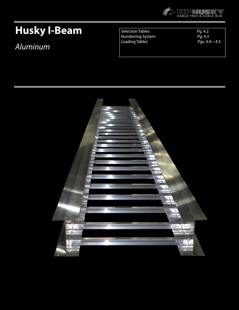
4.1
Husky I-Beam Aluminum
Selection Tables Pg. 4.2Numbering System Pg. 4.3 Loading Tables Pgs. 4.4—4.5
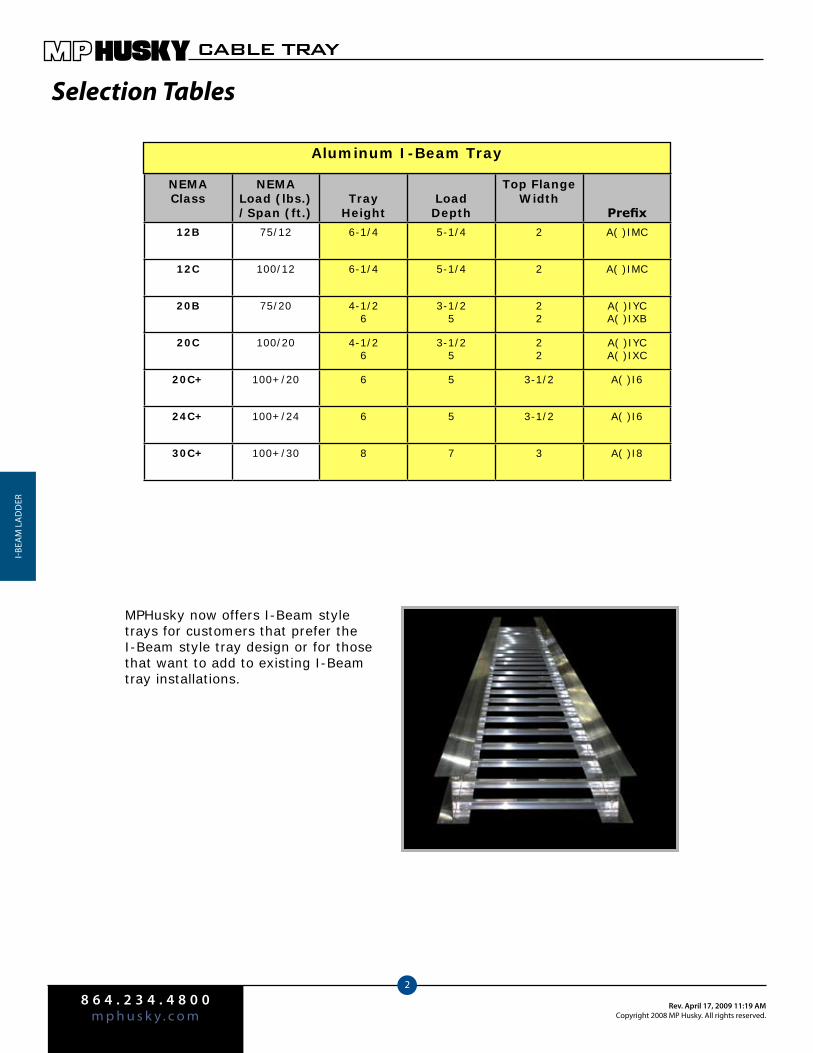
8 6 4 . 2 3 4 . 4 8 0 0m p h u s k y . c o m
Rev. April 17, 2009 11:19 AMCopyright 2008 MP Husky. All rights reserved.
CABLE TRAY
2
i-beA
M L
Ad
der
Selection Tables
NEMAClass
NEMALoad (lbs.)/Span (ft.)
TrayHeight
LoadDepth
Top FlangeWidth
Prefix
12B 75/12 6-1/4 5-1/4 2 A( )IMC
12C 100/12 6-1/4 5-1/4 2 A( )IMC
20B 75/20 4-1/26
3-1/25
22
A( )IYCA( )IXB
20C 100/20 4-1/26
3-1/25
22
A( )IYCA( )IXC
20C+ 100+/20 6 5 3-1/2 A( )I6
24C+ 100+/24 6 5 3-1/2 A( )I6
30C+ 100+/30 8 7 3 A( )I8
Aluminum I-Beam Tray
MPHusky now offers I-Beam style trays for customers that prefer the I-Beam style tray design or for those that want to add to existing I-Beam tray installations.

8 6 4 . 2 3 4 . 4 8 0 0m p h u s k y . c o mRev. April 17, 2009 11:19 AM
Copyright 2008 MP Husky. All rights reserved.
CABLE TRAY
3
i-beAM
LAd
der
Numbering System
Other Technical Data
A9IMC-24-144
Materials:
A= Aluminum
Rung Spacing:
6”9”12”18”
Tray Types:
IYC = 4-1/2” High 20CIMC= 6-1/4 High 12C
IXB= 6 High 20BIXC= 6” High 20CI6= 6” High 24C+I8= 8” High 30C+
Lengths:
120= 10’144= 12’240= 20’288= 24’
360= 30’ (I8 Only)
Except I6 &I8 Except I6 &I8
Depth: 4-1/2, 6 & 8 inchesFittings:12, 24 & 36 inch radiusSplice Plates:Bolted splice connectorsSafety Factor: 1.5Rung Options:I-Beam tray can be supplied with optional slotted or strut type rungs for ease of securing cables with tie wraps, strut clamps or accessories.
(For other tray sizes or specifications, please consult the factory)
Rung Dimensions
Widths:
6”9”12”18”24”30”36”
A 9 IMC- 24- 144
MaterialRung
SpacingTray Type
Width in Inches
Length in Inches
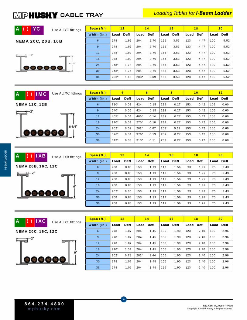
8 6 4 . 2 3 4 . 4 8 0 0m p h u s k y . c o m
Rev. April 17, 2009 11:19 AMCopyright 2008 MP Husky. All rights reserved.
CABLE TRAY
4
i-beA
M L
Ad
der
Span (ft.) 4 6 8 10 12
Width (in.) Load Defl Load Defl Load Defl Load Defl Load Defl
6 810* 0.08 424 0.15 239 0.27 153 0.42 106 0.60
9 540* 0.05 424 0.15 239 0.27 153 0.42 106 0.60
12 405* 0.04 405* 0.14 239 0.27 153 0.42 106 0.60
18 270* 0.03 270* 0.10 239 0.27 153 0.42 106 0.60
24 202* 0.02 202* 0.07 202* 0.19 153 0.42 106 0.60
30 376* 0.04 376* 0.13 239 0.27 153 0.42 106 0.60
36 313* 0.03 313* 0.11 239 0.27 153 0.42 106 0.60
Span (ft.) 12 14 16 18 20
Width (in.) Load Defl Load Defl Load Defl Load Defl Load Defl
6 208 0.88 153 1.19 117 1.56 93 1.97 75 2.43
9 208 0.88 153 1.19 117 1.56 93 1.97 75 2.43
12 208 0.88 153 1.19 117 1.56 93 1.97 75 2.43
18 208 0.88 153 1.19 117 1.56 93 1.97 75 2.43
24 202* 0.86 153 1.19 117 1.56 93 1.97 75 2.43
30 208 0.88 153 1.19 117 1.56 93 1.97 75 2.43
36 208 0.88 153 1.19 117 1.56 93 1.97 75 2.43
Span (ft.) 12 14 16 18 20
Width (in.) Load Defl Load Defl Load Defl Load Defl Load Defl
6 278 1.07 204 1.45 156 1.90 123 2.40 100 2.96
9 278 1.07 204 1.45 156 1.90 123 2.40 100 2.96
12 278 1.07 204 1.45 156 1.90 123 2.40 100 2.96
18 270* 1.04 204 1.45 156 1.90 123 2.40 100 2.96
24 202* 0.78 202* 1.44 156 1.90 123 2.40 100 2.96
30 278 1.07 204 1.45 156 1.90 123 2.40 100 2.96
36 278 1.07 204 1.45 156 1.90 123 2.40 100 2.96
Span (ft.) 12 14 16 18 20
Width (in.) Load Defl Load Defl Load Defl Load Defl Load Defl
6 278 1.99 204 2.70 156 3.53 123 4.47 100 5.52
9 278 1.99 204 2.70 156 3.53 123 4.47 100 5.52
12 278 1.99 204 2.70 156 3.53 123 4.47 100 5.52
18 278 1.99 204 2.70 156 3.53 123 4.47 100 5.52
24 248* 1.78 204 2.70 156 3.53 123 4.47 100 5.52
30 243* 1.74 204 2.70 156 3.53 123 4.47 100 5.52
36 203* 1.45 203* 2.69 156 3.53 123 4.47 100 5.52
Use ALIMC fittings
NEMA 12C, 12B
A IMC( )
Use ALIXB fittings
NEMA 20B, 16C, 12C
A IXB( )
Use ALIXC fittings
NEMA 20C, 16C, 12C
A IXC( )
A IYC( )
NEMA 20C, 20B, 16B
Use ALIYC fittings
Loading Tables for I-Beam Ladder
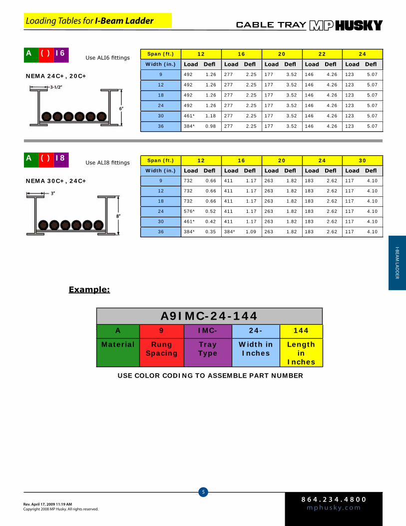
8 6 4 . 2 3 4 . 4 8 0 0m p h u s k y . c o mRev. April 17, 2009 11:19 AM
Copyright 2008 MP Husky. All rights reserved.
CABLE TRAY
5
i-beAM
LAd
der
Span (ft.) 12 16 20 22 24
Width (in.) Load Defl Load Defl Load Defl Load Defl Load Defl
9 492 1.26 277 2.25 177 3.52 146 4.26 123 5.07
12 492 1.26 277 2.25 177 3.52 146 4.26 123 5.07
18 492 1.26 277 2.25 177 3.52 146 4.26 123 5.07
24 492 1.26 277 2.25 177 3.52 146 4.26 123 5.07
30 461* 1.18 277 2.25 177 3.52 146 4.26 123 5.07
36 384* 0.98 277 2.25 177 3.52 146 4.26 123 5.07
A ( ) I6Use ALI6 fittings
NEMA 24C+, 20C+
Span (ft.) 12 16 20 24 30
Width (in.) Load Defl Load Defl Load Defl Load Defl Load Defl
9 732 0.66 411 1.17 263 1.82 183 2.62 117 4.10
12 732 0.66 411 1.17 263 1.82 183 2.62 117 4.10
18 732 0.66 411 1.17 263 1.82 183 2.62 117 4.10
24 576* 0.52 411 1.17 263 1.82 183 2.62 117 4.10
30 461* 0.42 411 1.17 263 1.82 183 2.62 117 4.10
36 384* 0.35 384* 1.09 263 1.82 183 2.62 117 4.10
A ( ) I8Use ALI8 fittings
NEMA 30C+, 24C+
A9IMC-24-144
USE COLOR CODING TO ASSEMBLE PART NUMBER
Example:
Loading Tables for I-Beam Ladder
A 9 IMC- 24- 144
Material Rung Spacing
Tray Type
Width in Inches
Length in
Inches
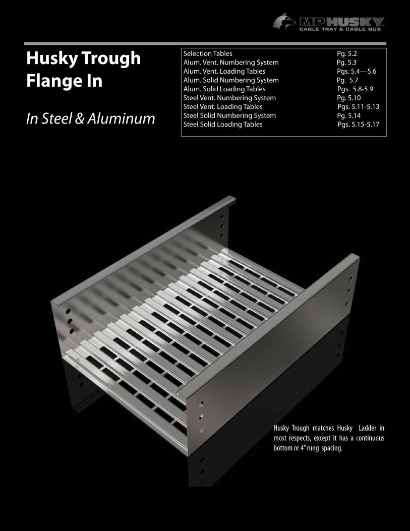
5.1
Husky TroughFlange In
In Steel & Aluminum
Selection Tables Pg. 5.2 Alum. Vent. Numbering System Pg. 5.3Alum. Vent. Loading Tables Pgs. 5.4—5.6Alum. Solid Numbering System Pg. 5.7Alum. Solid Loading Tables Pgs. 5.8-5.9Steel Vent. Numbering System Pg. 5.10Steel Vent. Loading Tables Pgs. 5.11-5.13Steel Solid Numbering System Pg. 5.14Steel Solid Loading Tables Pgs. 5.15-5.17
Husky Trough matches Husky Ladder in most respects, except it has a continuous bottom or 4” rung spacing.
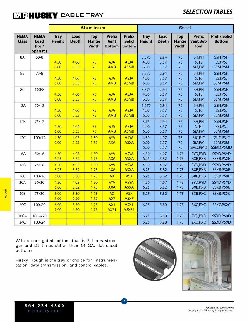
8 6 4 . 2 3 4 . 4 8 0 0m p h u s k y . c o m
Rev. April 16, 2009 4:20 PMCopyright 2008 MP Husky. All rights reserved.
CABLE TRAY
2
Tro
ug
H
SELECTION TABLES
Aluminum Steel
With a corrugated bottom that is 3 times stron-ger and 21 times stiffer than 14 GA. flat sheet bottoms.
Husky Trough is the tray of choice for instrumen-tation, data transmission, and control cables.
NEMAClass
NEMA Load (lbs./
Span ft.)
Tray Height
Load Depth
Top Flange Width
Prefix Vent
Bottom
Prefix Solid
Bottom
Tray Height
Load Depth
Top Flange Width
Prefix Vent Bot-
tom
Prefix Solid Bottom
8A 50/84.506.00
4.065.53
.75
.75AJAAMB
ASJAASMB
3.3754.006.00
2.943.575.57
.75
.75
.75
SH,PHSJ,PJ
SM,PM
SSH,PSHSSJ,PSJ
SSM,PSM
8B 75/84.506.00
4.065.53
.75
.75AJAAMB
ASJAASMB
3.3754.006.00
2.943.575.57
.75
.75
.75
SH,PHSJ,PJ
SM,PM
SSH,PSHSSJ,PSJ
SSM,PSM
8C 100/84.506.00
4.065.53
.75
.75AJAAMB
ASJAASMB
3.3754.006.00
2.943.575.57
.75
.75
.75
SH,PHSJ,PJ
SM,PM
SSH,PSHSSJ,PSJ
SSM,PSM
12A 50/124.506.00
4.065.53
.75
.75AJAAMB
ASJAASMB
3.3754.006.00
2.943.575.57
.75
.75
.75
SH,PHSJ,PJ
SM,PM
SSH,PSHSSJ,PSJ
SSM,PSM
12B 75/124.506.00
4.045.53
.75
.75AJAAMB
ASJAASMB
3.754.006.00
2.943.575.57
.75
.75
.75
SH,PHSJ,PJ
SM,PM
SSH,PSHSSJ,PSJ
SSM,PSM
12C 100/12 4.506.00
4.035.52
1.501.75
AYAAXA
ASYAASXA
4.506.006.00
4.075.575.57
.75
.75
.75
SJC,PJCSM,PM
SMD,PMD
SSJC,PSJCSSM,PSM
SSMD,PSMD
16A 50/16 4.506.25
4.035.52
1.501.75
AYAAXA
ASYAASXA
4.506.25
4.075.82
1.751.75
SYD,PYDSXB,PXB
SSYD,PSYDSSXB,PSXB
16B 75/16 4.506.25
4.035.52
1.501.75
AYAAXA
ASYAASXA
4.506.25
4.075.82
1.751.75
SYD,PYDSXB,PXB
SSYD,PSYDSSXB,PSXB
16C 100/16 6.00 5.50 1.75 AX ASX 6.25 5.82 1.75 SXB,PXB SSXB,PSXB
20A 50/20 4.506.00
4.035.52
1.501.75
AYAAXA
ASYAASXA
4.506.25
4.075.82
1.751.75
SYD,PYDSXB,PXB
SSYD,PSYDSSXB,PSXB
20B 75/20 6.007.00
5.506.50
1.751.75
AXAX7
ASXASX7
6.25 5.82 1.75 SXB,PXC SSXB,PSXC
20C 100/20 6.007.00
5.506.50
1.751.75
AX1AX71
ASX1ASX71
6.25 5.80 1.75 SXC,PXC SSXC,PSXC
20C+ 100+/20 6.25 5.80 1.75 SXD,PXD SSXD,PSXD
24C 100/24 6.25 5.80 1.75 SXD,PXD SSXD,PSXD

8 6 4 . 2 3 4 . 4 8 0 0m p h u s k y . c o mRev. April 16, 2009 4:20 PM
Copyright 2008 MP Husky. All rights reserved.
CABLE TRAY
3
Trou
gH
Aluminum Ventilated Trough Numbering System
Other Technical DataDepth:4-1/2, 6 & 7 inches nominalFittings:12, 24, or 36 inch standard radii (See the Fittings Section 9 of this catalog) Trough Bottoms:All troughs 6” - 24” wide have corrugated ventilated bottoms. 30” and 36” wide have 4” rung spacing. Splice Plates:Straight sections and fittings are supplied with splice plates and hardware.Safety Factor:1.5 NEMA Standard
(For other tray sizes or specifications, please consult the factory)
Bottom Dimensions
AJA-24-144
Materials:A=Aluminum
S=HDGAF SteelP=Mill-Galv. Steel
4=Stainless Steel 3046=Stainless Steel 316
BottomLeave this space
blank for 6”-24” WideVentilated TroughInsert “4” for 4”
Rung Spacing 30” & 36” wide Ventilated
Trough
Tray Types:Aluminum
JA, JB, MB, YA, XA, X, X1, X7, X71
Widths:6”9”12”18”24”30”36”
Lengths:JA, JB, MB
available in 10’ (120”) & 12’ (144”) only
All others available in 10’ (120”), 12’ (144”),
20’ (240”) & 24’ (288”)
A ( ) JA- 24- 144
Material BottomTray Type
Width in Inches
Length in Inches
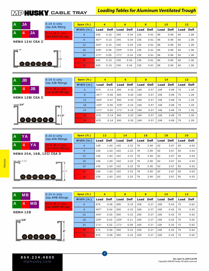
8 6 4 . 2 3 4 . 4 8 0 0m p h u s k y . c o m
Rev. April 16, 2009 4:20 PMCopyright 2008 MP Husky. All rights reserved.
CABLE TRAY
4
Tro
ug
H
Loading Tables for Aluminum Ventilated Trough
Span (ft.) 4 6 8 10 12
Width (in.) Load Defl Load Defl Load Defl Load Defl Load Defl
6 540 0.15 240 0.34 135 0.61 86 0.96 60 1.38
9 457* 0.13 240 0.34 135 0.61 86 0.96 60 1.38
12 343* 0.10 240 0.34 135 0.61 86 0.96 60 1.38
18 229* 0.06 229* 0.32 135 0.61 86 0.96 60 1.38
24 171* 0.05 171* 0.24 135 0.61 86 0.96 60 1.38
30 540 0.15 240 0.34 135 0.61 86 0.96 60 1.38
36 540 0.15 240 0.34 135 0.61 86 0.96 60 1.38
Span (ft.) 4 6 8 10 12
Width (in.) Load Defl Load Defl Load Defl Load Defl Load Defl
6 675 0.14 300 0.32 169 0.57 108 0.89 75 1.28
9 457* 0.09 300 0.32 169 0.57 108 0.89 75 1.28
12 343* 0.07 300 0.32 169 0.57 108 0.89 75 1.28
18 229* 0.05 229* 0.24 169 0.57 108 0.89 75 1.28
24 171* 0.04 171* 0.18 169 0.57 108 0.89 75 1.28
30 675 0.14 300 0.32 169 0.57 108 0.89 75 1.28
36 675 0.14 300 0.32 169 0.57 108 0.89 75 1.28
Span (ft.) 12 14 16 18 20
Width (in.) Load Defl Load Defl Load Defl Load Defl Load Defl
6 139 1.63 102 2.22 78 2.90 62 3.67 50 4.53
9 139 1.63 102 2.22 78 2.90 62 3.67 50 4.53
12 139 1.63 102 2.22 78 2.90 62 3.67 50 4.53
18 139 1.63 102 2.22 78 2.90 62 3.67 50 4.53
24 139 1.63 102 2.22 78 2.90 62 3.67 50 4.53
30 139 1.63 102 2.22 78 2.90 62 3.67 50 4.53
36 139 1.63 102 2.22 78 2.90 62 3.67 50 4.53
A JA 6-24 in onlyUse AJA fitting
NEMA 12A/CSA C
A JB4
6-24 in onlyUse AJB fittings
NEMA 12B/CSA C
A YA4
NEMA 20A, 16B, 12C/CSA D
A JA4 30 & 36 in only Use A4JA fittings
A JB
30 & 36 in onlyUse A4JB fittings
A YA 6-24 in onlyUse AYA fittings
30 & 36 in onlyUse A4YA fittings
Span (ft.) 4 6 8 10 12
Width (in.) Load Defl Load Defl Load Defl Load Defl Load Defl
6 675 0.06 300 0.15 169 0.27 108 0.43 75 0.62
9 457* 0.04 300 0.15 169 0.27 108 0.43 75 0.62
12 343* 0.03 300 0.15 169 0.27 108 0.43 75 0.62
18 229* 0.02 229* 0.11 169 0.27 108 0.43 75 0.62
24 171* 0.02 171* 0.09 169 0.27 108 0.43 75 0.62
30 675 0.06 300 0.15 169 0.27 108 0.43 75 0.62
36 675 0.06 300 0.15 169 0.27 108 0.43 75 0.62
A MB4
NEMA 12B
A MB 6-24 in onlyUse AMB fittings
30 & 36 in onlyUse A4MB fittings
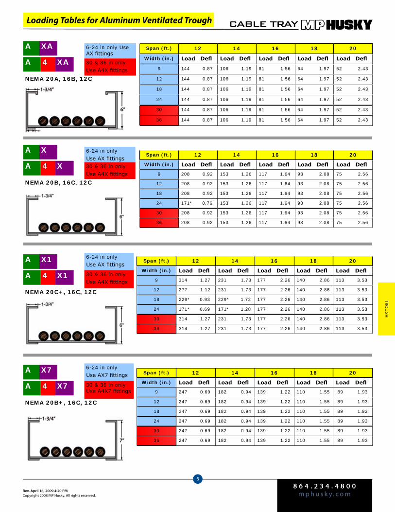
8 6 4 . 2 3 4 . 4 8 0 0m p h u s k y . c o mRev. April 16, 2009 4:20 PM
Copyright 2008 MP Husky. All rights reserved.
CABLE TRAY
5
Trou
gH
Span (ft.) 12 14 16 18 20
Width (in.) Load Defl Load Defl Load Defl Load Defl Load Defl
9 208 0.92 153 1.26 117 1.64 93 2.08 75 2.56
12 208 0.92 153 1.26 117 1.64 93 2.08 75 2.56
18 208 0.92 153 1.26 117 1.64 93 2.08 75 2.56
24 171* 0.76 153 1.26 117 1.64 93 2.08 75 2.56
30 208 0.92 153 1.26 117 1.64 93 2.08 75 2.56
36 208 0.92 153 1.26 117 1.64 93 2.08 75 2.56
A X4
NEMA 20B, 16C, 12C
A XA4
NEMA 20A, 16B, 12C
Span (ft.) 12 14 16 18 20
Width (in.) Load Defl Load Defl Load Defl Load Defl Load Defl
9 144 0.87 106 1.19 81 1.56 64 1.97 52 2.43
12 144 0.87 106 1.19 81 1.56 64 1.97 52 2.43
18 144 0.87 106 1.19 81 1.56 64 1.97 52 2.43
24 144 0.87 106 1.19 81 1.56 64 1.97 52 2.43
30 144 0.87 106 1.19 81 1.56 64 1.97 52 2.43
36 144 0.87 106 1.19 81 1.56 64 1.97 52 2.43
A XA
30 & 36 in onlyUse A4X fittings
6-24 in onlyUse AX fittings30 & 36 in onlyUse A4X fittings
A X
6-24 in only Use AX fittings
A X14
NEMA 20C+, 16C, 12C
Span (ft.) 12 14 16 18 20
Width (in.) Load Defl Load Defl Load Defl Load Defl Load Defl
9 314 1.27 231 1.73 177 2.26 140 2.86 113 3.53
12 277 1.12 231 1.73 177 2.26 140 2.86 113 3.53
18 229* 0.93 229* 1.72 177 2.26 140 2.86 113 3.53
24 171* 0.69 171* 1.28 177 2.26 140 2.86 113 3.53
30 314 1.27 231 1.73 177 2.26 140 2.86 113 3.53
36 314 1.27 231 1.73 177 2.26 140 2.86 113 3.53
A X1 6-24 in onlyUse AX fittings
30 & 36 in onlyUse A4X fittings
A X74
NEMA 20B+, 16C, 12C
Span (ft.) 12 14 16 18 20
Width (in.) Load Defl Load Defl Load Defl Load Defl Load Defl
9 247 0.69 182 0.94 139 1.22 110 1.55 89 1.93
12 247 0.69 182 0.94 139 1.22 110 1.55 89 1.93
18 247 0.69 182 0.94 139 1.22 110 1.55 89 1.93
24 247 0.69 182 0.94 139 1.22 110 1.55 89 1.93
30 247 0.69 182 0.94 139 1.22 110 1.55 89 1.93
36 247 0.69 182 0.94 139 1.22 110 1.55 89 1.93
A X7 6-24 in onlyUse AX7 fittings
30 & 36 in onlyUse A4X7 fittings
Loading Tables for Aluminum Ventilated Trough
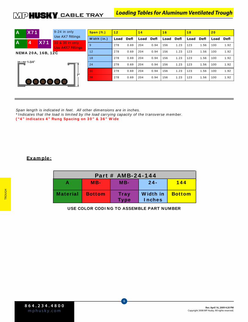
8 6 4 . 2 3 4 . 4 8 0 0m p h u s k y . c o m
Rev. April 16, 2009 4:20 PMCopyright 2008 MP Husky. All rights reserved.
CABLE TRAY
6
Tro
ug
H
Part # AMB-24-144
A X714
NEMA 20A, 16B, 12C
Span (ft.) 12 14 16 18 20
Width (in.) Load Defl Load Defl Load Defl Load Defl Load Defl
9 278 0.69 204 0.94 156 1.23 123 1.56 100 1.92
12 278 0.69 204 0.94 156 1.23 123 1.56 100 1.92
18 278 0.69 204 0.94 156 1.23 123 1.56 100 1.92
24 278 0.69 204 0.94 156 1.23 123 1.56 100 1.92
30 278 0.69 204 0.94 156 1.23 123 1.56 100 1.92
36 278 0.69 204 0.94 156 1.23 123 1.56 100 1.92
A X71 9-24 in onlyUse AX7 fittings
30 & 36 in onlyUse A4X7 fittings
Example:
A MB- MB- 24- 144
Material Bottom Tray Type
Width in Inches
Bottom
USE COLOR CODING TO ASSEMBLE PART NUMBER
Span length is indicated in feet. All other dimensions are in inches.*Indicates that the load is limited by the load carrying capacity of the transverse member.(“4” indicates 4” Rung Spacing on 30” & 36” Wide
Loading Tables for Aluminum Ventilated Trough
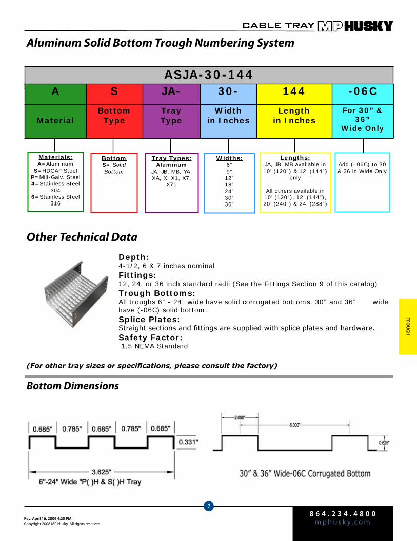
8 6 4 . 2 3 4 . 4 8 0 0m p h u s k y . c o mRev. April 16, 2009 4:20 PM
Copyright 2008 MP Husky. All rights reserved.
CABLE TRAY
7
Trou
gH
Aluminum Solid Bottom Trough Numbering System
Other Technical DataDepth:4-1/2, 6 & 7 inches nominalFittings:12, 24, or 36 inch standard radii (See the Fittings Section 9 of this catalog) Trough Bottoms:All troughs 6” - 24” wide have solid corrugated bottoms. 30” and 36” wide have (-06C) solid bottom. Splice Plates:Straight sections and fittings are supplied with splice plates and hardware.Safety Factor:
1.5 NEMA Standard
(For other tray sizes or specifications, please consult the factory)
Bottom Dimensions
ASJA-30-144
Materials:A=Aluminum
S=HDGAF SteelP=Mill-Galv. Steel4=Stainless Steel
3046=Stainless Steel
316
BottomS= Solid Bottom
Tray Types:Aluminum
JA, JB, MB, YA, XA, X, X1, X7,
X71
Widths:6”9”12”18”24”30”36”
Lengths:JA, JB, MB available in 10’ (120”) & 12’ (144”)
only
All others available in 10’ (120”), 12’ (144”), 20’ (240”) & 24’ (288”)
Add (–06C) to 30 & 36 in Wide Only
A S JA- 30- 144 -06C
MaterialBottom
TypeTrayType
Widthin Inches
Lengthin Inches
For 30” & 36”
Wide Only
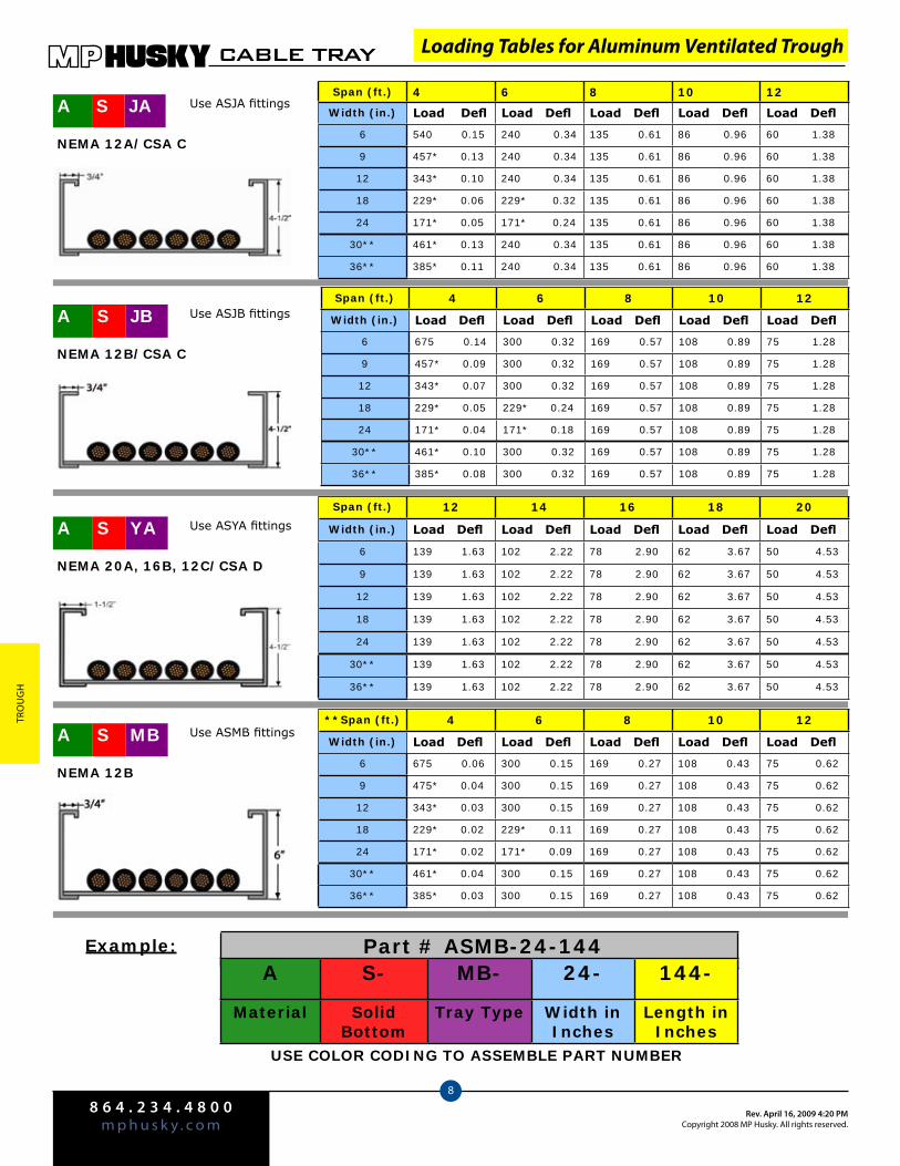
8 6 4 . 2 3 4 . 4 8 0 0m p h u s k y . c o m
Rev. April 16, 2009 4:20 PMCopyright 2008 MP Husky. All rights reserved.
CABLE TRAY
8
Tro
ug
H
Span (ft.) 4 6 8 10 12
Width (in.) Load Defl Load Defl Load Defl Load Defl Load Defl
6 540 0.15 240 0.34 135 0.61 86 0.96 60 1.38
9 457* 0.13 240 0.34 135 0.61 86 0.96 60 1.38
12 343* 0.10 240 0.34 135 0.61 86 0.96 60 1.38
18 229* 0.06 229* 0.32 135 0.61 86 0.96 60 1.38
24 171* 0.05 171* 0.24 135 0.61 86 0.96 60 1.38
30** 461* 0.13 240 0.34 135 0.61 86 0.96 60 1.38
36** 385* 0.11 240 0.34 135 0.61 86 0.96 60 1.38
Span (ft.) 4 6 8 10 12
Width (in.) Load Defl Load Defl Load Defl Load Defl Load Defl
6 675 0.14 300 0.32 169 0.57 108 0.89 75 1.28
9 457* 0.09 300 0.32 169 0.57 108 0.89 75 1.28
12 343* 0.07 300 0.32 169 0.57 108 0.89 75 1.28
18 229* 0.05 229* 0.24 169 0.57 108 0.89 75 1.28
24 171* 0.04 171* 0.18 169 0.57 108 0.89 75 1.28
30** 461* 0.10 300 0.32 169 0.57 108 0.89 75 1.28
36** 385* 0.08 300 0.32 169 0.57 108 0.89 75 1.28
Span (ft.) 12 14 16 18 20
Width (in.) Load Defl Load Defl Load Defl Load Defl Load Defl
6 139 1.63 102 2.22 78 2.90 62 3.67 50 4.53
9 139 1.63 102 2.22 78 2.90 62 3.67 50 4.53
12 139 1.63 102 2.22 78 2.90 62 3.67 50 4.53
18 139 1.63 102 2.22 78 2.90 62 3.67 50 4.53
24 139 1.63 102 2.22 78 2.90 62 3.67 50 4.53
30** 139 1.63 102 2.22 78 2.90 62 3.67 50 4.53
36** 139 1.63 102 2.22 78 2.90 62 3.67 50 4.53
NEMA 12A/CSA C
A JBS Use ASJB fittings
NEMA 12B/CSA C
A YAS
NEMA 20A, 16B, 12C/CSA D
A JAS
Use ASYA fittings
Use ASJA fittings
Example:
**Span (ft.) 4 6 8 10 12
Width (in.) Load Defl Load Defl Load Defl Load Defl Load Defl
6 675 0.06 300 0.15 169 0.27 108 0.43 75 0.62
9 475* 0.04 300 0.15 169 0.27 108 0.43 75 0.62
12 343* 0.03 300 0.15 169 0.27 108 0.43 75 0.62
18 229* 0.02 229* 0.11 169 0.27 108 0.43 75 0.62
24 171* 0.02 171* 0.09 169 0.27 108 0.43 75 0.62
30** 461* 0.04 300 0.15 169 0.27 108 0.43 75 0.62
36** 385* 0.03 300 0.15 169 0.27 108 0.43 75 0.62
A MBS
NEMA 12B
Use ASMB fittings
Loading Tables for Aluminum Ventilated Trough
Part # ASMB-24-144
USE COLOR CODING TO ASSEMBLE PART NUMBER
A S- MB- 24- 144-
Material Solid Bottom
Tray Type Width in Inches
Length in Inches
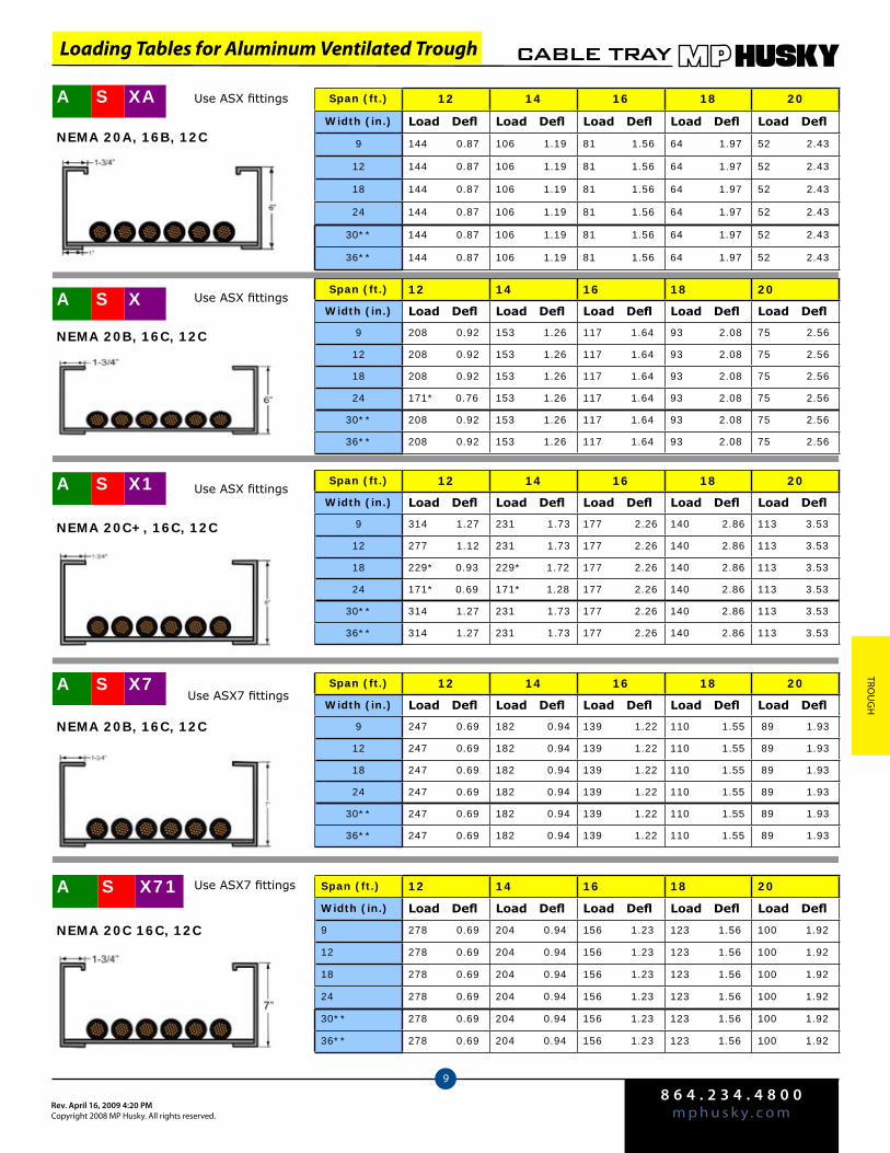
8 6 4 . 2 3 4 . 4 8 0 0m p h u s k y . c o mRev. April 16, 2009 4:20 PM
Copyright 2008 MP Husky. All rights reserved.
CABLE TRAY
9
Trou
gH
Span (ft.) 12 14 16 18 20
Width (in.) Load Defl Load Defl Load Defl Load Defl Load Defl
9 208 0.92 153 1.26 117 1.64 93 2.08 75 2.56
12 208 0.92 153 1.26 117 1.64 93 2.08 75 2.56
18 208 0.92 153 1.26 117 1.64 93 2.08 75 2.56
24 171* 0.76 153 1.26 117 1.64 93 2.08 75 2.56
30** 208 0.92 153 1.26 117 1.64 93 2.08 75 2.56
36** 208 0.92 153 1.26 117 1.64 93 2.08 75 2.56
A XS
NEMA 20B, 16C, 12C
A XAS
NEMA 20A, 16B, 12C
Use ASX fittings
Use ASX fittings
Span (ft.) 12 14 16 18 20
Width (in.) Load Defl Load Defl Load Defl Load Defl Load Defl
9 144 0.87 106 1.19 81 1.56 64 1.97 52 2.43
12 144 0.87 106 1.19 81 1.56 64 1.97 52 2.43
18 144 0.87 106 1.19 81 1.56 64 1.97 52 2.43
24 144 0.87 106 1.19 81 1.56 64 1.97 52 2.43
30** 144 0.87 106 1.19 81 1.56 64 1.97 52 2.43
36** 144 0.87 106 1.19 81 1.56 64 1.97 52 2.43
A X1S
NEMA 20C+, 16C, 12C
Span (ft.) 12 14 16 18 20
Width (in.) Load Defl Load Defl Load Defl Load Defl Load Defl
9 314 1.27 231 1.73 177 2.26 140 2.86 113 3.53
12 277 1.12 231 1.73 177 2.26 140 2.86 113 3.53
18 229* 0.93 229* 1.72 177 2.26 140 2.86 113 3.53
24 171* 0.69 171* 1.28 177 2.26 140 2.86 113 3.53
30** 314 1.27 231 1.73 177 2.26 140 2.86 113 3.53
36** 314 1.27 231 1.73 177 2.26 140 2.86 113 3.53
Use ASX fittings
A X7S
NEMA 20B, 16C, 12C
Span (ft.) 12 14 16 18 20
Width (in.) Load Defl Load Defl Load Defl Load Defl Load Defl
9 247 0.69 182 0.94 139 1.22 110 1.55 89 1.93
12 247 0.69 182 0.94 139 1.22 110 1.55 89 1.93
18 247 0.69 182 0.94 139 1.22 110 1.55 89 1.93
24 247 0.69 182 0.94 139 1.22 110 1.55 89 1.93
30** 247 0.69 182 0.94 139 1.22 110 1.55 89 1.93
36** 247 0.69 182 0.94 139 1.22 110 1.55 89 1.93
Use ASX7 fittings
A X71S
NEMA 20C 16C, 12C
Span (ft.) 12 14 16 18 20
Width (in.) Load Defl Load Defl Load Defl Load Defl Load Defl
9 278 0.69 204 0.94 156 1.23 123 1.56 100 1.92
12 278 0.69 204 0.94 156 1.23 123 1.56 100 1.92
18 278 0.69 204 0.94 156 1.23 123 1.56 100 1.92
24 278 0.69 204 0.94 156 1.23 123 1.56 100 1.92
30** 278 0.69 204 0.94 156 1.23 123 1.56 100 1.92
36** 278 0.69 204 0.94 156 1.23 123 1.56 100 1.92
Use ASX7 fittings
Loading Tables for Aluminum Ventilated Trough
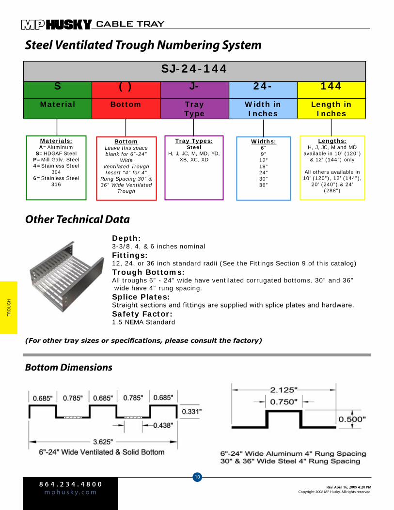
8 6 4 . 2 3 4 . 4 8 0 0m p h u s k y . c o m
Rev. April 16, 2009 4:20 PMCopyright 2008 MP Husky. All rights reserved.
CABLE TRAY
10
Tro
ug
H
Steel Ventilated Trough Numbering System
Other Technical DataDepth:3-3/8, 4, & 6 inches nominalFittings:12, 24, or 36 inch standard radii (See the Fittings Section 9 of this catalog) Trough Bottoms:All troughs 6” - 24” wide have ventilated corrugated bottoms. 30” and 36” wide have 4” rung spacing. Splice Plates:Straight sections and fittings are supplied with splice plates and hardware.Safety Factor:1.5 NEMA Standard
(For other tray sizes or specifications, please consult the factory)
Bottom Dimensions
S ( ) J- 24- 144
Material Bottom Tray Type
Width in Inches
Length in Inches
SJ-24-144
Materials:A=Aluminum
S=HDGAF SteelP=Mill Galv. Steel4=Stainless Steel
3046=Stainless Steel
316
BottomLeave this space blank for 6”-24”
Wide Ventilated TroughInsert “4” for 4”
Rung Spacing 30” & 36” Wide Ventilated
Trough
Tray Types:Steel
H, J, JC, M, MD, YD, XB, XC, XD
Widths:6”9”12”18”24”30”36”
Lengths:H, J, JC, M and MD
available in 10’ (120”) & 12’ (144”) only
All others available in 10’ (120”), 12’ (144”),
20’ (240”) & 24’ (288”)

8 6 4 . 2 3 4 . 4 8 0 0m p h u s k y . c o mRev. April 16, 2009 4:20 PM
Copyright 2008 MP Husky. All rights reserved.
CABLE TRAY
11
Trou
gH
Loading Tables for Steel Ventilated Trough
Span (ft.) 4 6 8 10 12
Width (in.) Load Defl Load Defl Load Defl Load Defl Load Defl
6 689 0.15 306 0.35 172 0.62 110 0.97 76 1.40
9 591* 0.13 306 0.35 172 0.62 110 0.97 76 1.40
12 443* 0.10 306 0.35 172 0.62 110 0.97 76 1.40
18 295* 0.06 295* 0.33 172 0.62 110 0.97 76 1.40
24 221* 0.05 221* 0.25 172 0.62 110 0.97 76 1.40
30 689 0.15 306 0.35 172 0.62 110 0.97 76 1.40
36 577* 0.13 306 0.35 172 0.62 110 0.97 76 1.40
Span (ft.) 4 6 8 10 12
Width (in.) Load Defl Load Defl Load Defl Load Defl Load Defl
6 749 0.11 333 0.24 187 0.44 119 0.69 83 0.99
9 591* 0.08 333 0.24 187 0.44 119 0.69 83 0.99
12 443* 0.06 333 0.24 187 0.44 119 0.69 83 0.99
18 295* 0.04 295* 0.22 187 0.44 119 0.69 83 0.99
24 221* 0.03 221* 0.16 187 0.44 119 0.69 83 0.99
30 692* 0.10 333 0.24 187 0.44 119 0.69 83 0.99
36 577* 0.09 333 0.24 187 0.44 119 0.69 83 0.99
Span (ft.) 4 6 8 10 12
Width (in.) Load Defl Load Defl Load Defl Load Defl Load Defl
6 887* 0.09 440 0.23 248 0.41 158 0.65 110 0.94
9 591* 0.08 440 0.23 248 0.41 158 0.65 110 0.94
12 443* 0.06 440 0.23 248 0.41 158 0.65 110 0.94
18 295* 0.03 295* 0.15 248 0.41 158 0.65 110 0.94
24 221* 0.02 221* 0.12 248 0.41 158 0.65 110 0.94
30 692* 0.07 440 0.23 248 0.41 158 0.65 110 0.94
36 577* 0.06 440 0.23 248 0.41 158 0.65 110 0.94
NEMA 12B
NEMA 12B/CSA C
NEMA 12C/CSA D on 3m
P H4
Use SH fittings
P H
S H4
S H
Hot Dip Galvanized After Fabrication
Mill-Galvanized
Use S4H fittings
Use PH fittings
Use P4H fittings
Use SJ fittings
P J
P J4
S J
Hot Dip Galvanized After Fabrication
Mill-Galvanized
Use S4J fittings
Use PJ fittings
Use P4J fittings
Use SJC fittings
P JC
P JC4
S JC
Hot Dip Galvanized After Fabrication
Mill-Galvanized
Use S4JC fittings
Use PJC fittings
Use P4JC fittings
Blue = Corrugated Bottom
Red = 4” Rung Spacing
Blue = Corrugated Bottom
Red = 4” Rung Spacing
Blue = Corrugated Bottom
Red = 4” Rung Spacing
S J4
S JC4
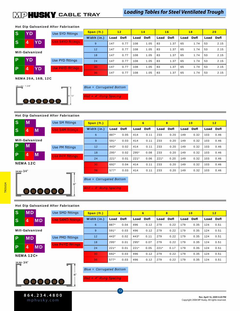
8 6 4 . 2 3 4 . 4 8 0 0m p h u s k y . c o m
Rev. April 16, 2009 4:20 PMCopyright 2008 MP Husky. All rights reserved.
CABLE TRAY
12
Tro
ug
H
Span (ft.) 12 14 16 18 20
Width (in.) Load Defl Load Defl Load Defl Load Defl Load Defl
9 147 0.77 108 1.05 83 1.37 65 1.74 53 2.15
12 147 0.77 108 1.05 83 1.37 65 1.74 53 2.15
18 147 0.77 108 1.05 83 1.37 65 1.74 53 2.15
24 147 0.77 108 1.05 83 1.37 65 1.74 53 2.15
30 147 0.77 108 1.05 83 1.37 65 1.74 53 2.15
36 147 0.77 108 1.05 83 1.37 65 1.74 53 2.15
NEMA 20A, 16B, 12C
Use SYD fittings
P YD
S YD
Hot Dip Galvanized After Fabrication
Mill-Galvanized
Use S4YD fittings
Use PYD fittings
Use P4YD fittings
Blue = Corrugated Bottom
Red = 4” Rung Spacing
Span (ft.) 4 6 8 10 12
Width (in.) Load Defl Load Defl Load Defl Load Defl Load Defl
6 887* 0.05 414 0.11 233 0.20 149 0.32 103 0.46
9 591* 0.03 414 0.11 233 0.20 149 0.32 103 0.46
12 443* 0.02 414 0.11 233 0.20 149 0.32 103 0.46
18 295* 0.02 295* 0.08 233 0.20 149 0.32 103 0.46
24 221* 0.01 221* 0.06 221* 0.20 149 0.32 103 0.46
30 692* 0.04 414 0.11 233 0.20 149 0.32 103 0.46
36 577* 0.03 414 0.11 233 0.20 149 0.32 103 0.46
NEMA 12C
Use SM fittingsS M
Hot Dip Galvanized After Fabrication
Mill-Galvanized
Use S4M fittings
Use PM fittings
Use P4M fittings
Blue = Corrugated Bottom
Red = 4” Rung Spacing
Span (ft.) 4 6 8 10 12
Width (in.) Load Defl Load Defl Load Defl Load Defl Load Defl
6 887* 0.04 496 0.12 279 0.22 179 0.35 124 0.51
9 591* 0.03 496 0.12 279 0.22 179 0.35 124 0.51
12 443* 0.02 443* 0.11 279 0.22 179 0.35 124 0.51
18 295* 0.01 295* 0.07 279 0.22 179 0.35 124 0.51
24 221* 0.01 221* 0.05 221* 0.17 179 0.35 124 0.51
30 692* 0.03 496 0.12 279 0.22 179 0.35 124 0.51
36 577* 0.03 496 0.12 279 0.22 179 0.35 124 0.51NEMA 12C+
P MD4
Use SMD fittings
P MD
S MD
Hot Dip Galvanized After Fabrication
Mill-Galvanized
Use S4MD fittings
Use PMD fittings
Use P4MD fittings
Blue = Corrugated Bottom
Red = 4” Rung Spacing
S MD4
S M4
P M
P M4
P YD4
S YD4
Loading Tables for Steel Ventilated Trough
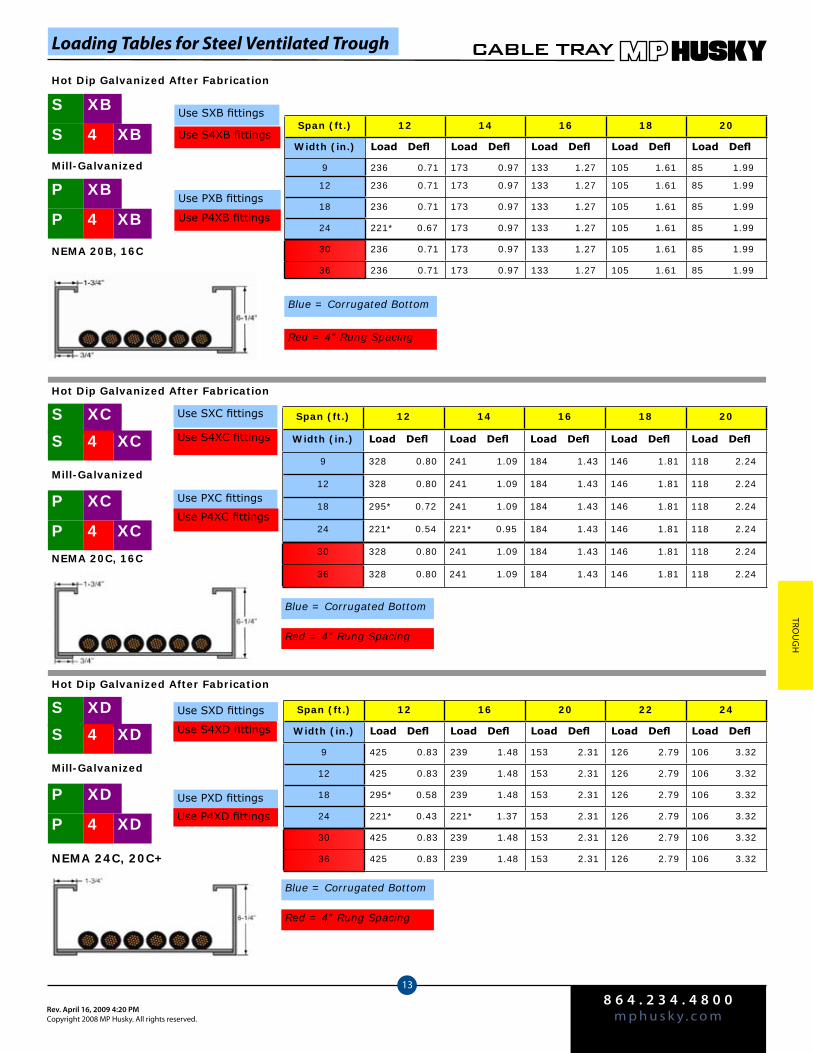
8 6 4 . 2 3 4 . 4 8 0 0m p h u s k y . c o mRev. April 16, 2009 4:20 PM
Copyright 2008 MP Husky. All rights reserved.
CABLE TRAY
13
Trou
gH
Loading Tables for Steel Ventilated Trough
Span (ft.) 12 14 16 18 20
Width (in.) Load Defl Load Defl Load Defl Load Defl Load Defl
9 236 0.71 173 0.97 133 1.27 105 1.61 85 1.99
12 236 0.71 173 0.97 133 1.27 105 1.61 85 1.99
18 236 0.71 173 0.97 133 1.27 105 1.61 85 1.99
24 221* 0.67 173 0.97 133 1.27 105 1.61 85 1.99
30 236 0.71 173 0.97 133 1.27 105 1.61 85 1.99
36 236 0.71 173 0.97 133 1.27 105 1.61 85 1.99
Span (ft.) 12 14 16 18 20
Width (in.) Load Defl Load Defl Load Defl Load Defl Load Defl
9 328 0.80 241 1.09 184 1.43 146 1.81 118 2.24
12 328 0.80 241 1.09 184 1.43 146 1.81 118 2.24
18 295* 0.72 241 1.09 184 1.43 146 1.81 118 2.24
24 221* 0.54 221* 0.95 184 1.43 146 1.81 118 2.24
30 328 0.80 241 1.09 184 1.43 146 1.81 118 2.24
36 328 0.80 241 1.09 184 1.43 146 1.81 118 2.24
Span (ft.) 12 16 20 22 24
Width (in.) Load Defl Load Defl Load Defl Load Defl Load Defl
9 425 0.83 239 1.48 153 2.31 126 2.79 106 3.32
12 425 0.83 239 1.48 153 2.31 126 2.79 106 3.32
18 295* 0.58 239 1.48 153 2.31 126 2.79 106 3.32
24 221* 0.43 221* 1.37 153 2.31 126 2.79 106 3.32
30 425 0.83 239 1.48 153 2.31 126 2.79 106 3.32
36 425 0.83 239 1.48 153 2.31 126 2.79 106 3.32
NEMA 20B, 16C
NEMA 20C, 16C
NEMA 24C, 20C+
Use SXB fittings
P XB
S XB4
S XB
Hot Dip Galvanized After Fabrication
Mill-Galvanized
Use S4XB fittings
Use PXB fittings
Use P4XB fittings
Blue = Corrugated Bottom
Red = 4” Rung Spacing
P XC4
Use SXC fittings
P XC
S XC
Hot Dip Galvanized After Fabrication
Mill-Galvanized
Use S4XC fittings
Use PXC fittings
Use P4XC fittings
Blue = Corrugated Bottom
Red = 4” Rung Spacing
P XD4
Use SXD fittings
P XD
S XD
Hot Dip Galvanized After Fabrication
Mill-Galvanized
Use S4XD fittings
Use PXD fittings
Use P4XD fittings
Blue = Corrugated Bottom
Red = 4” Rung Spacing
P XB4
S XC4
S XD4
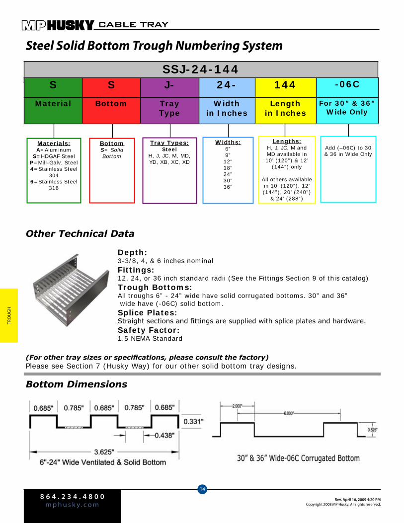
8 6 4 . 2 3 4 . 4 8 0 0m p h u s k y . c o m
Rev. April 16, 2009 4:20 PMCopyright 2008 MP Husky. All rights reserved.
CABLE TRAY
14
Tro
ug
H
Steel Solid Bottom Trough Numbering System
Other Technical Data
Depth:3-3/8, 4, & 6 inches nominalFittings:12, 24, or 36 inch standard radii (See the Fittings Section 9 of this catalog) Trough Bottoms:All troughs 6” - 24” wide have solid corrugated bottoms. 30” and 36” wide have (-06C) solid bottom. Splice Plates:Straight sections and fittings are supplied with splice plates and hardware.Safety Factor:1.5 NEMA Standard
(For other tray sizes or specifications, please consult the factory)Please see Section 7 (Husky Way) for our other solid bottom tray designs.
Bottom Dimensions
SSJ-24-144
Materials:A=Aluminum
S=HDGAF SteelP=Mill-Galv. Steel4=Stainless Steel
3046=Stainless Steel
316
BottomS= Solid Bottom
Tray Types:Steel
H, J, JC, M, MD, YD, XB, XC, XD
Widths:6”9”12”18”24”30”36”
Lengths:H, J, JC, M and MD available in 10’ (120”) & 12’
(144”) only
All others available in 10’ (120”), 12’ (144”), 20’ (240”)
& 24’ (288”)
Add (–06C) to 30 & 36 in Wide Only
S S J- 24- 144 -06C
Material Bottom TrayType
Width in Inches
Length in Inches
For 30” & 36” Wide Only
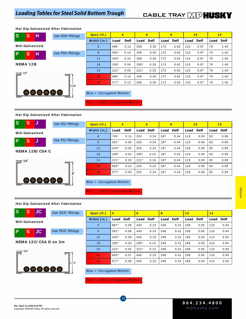
8 6 4 . 2 3 4 . 4 8 0 0m p h u s k y . c o mRev. April 16, 2009 4:20 PM
Copyright 2008 MP Husky. All rights reserved.
CABLE TRAY
15
Trou
gH
Loading Tables for Steel Solid Bottom Trough
Span (ft.) 4 6 8 10 12
Width (in.) Load Defl Load Defl Load Defl Load Defl Load Defl
6 689 0.15 306 0.35 172 0.62 110 0.97 76 1.40
9 591* 0.13 306 0.35 172 0.62 110 0.97 76 1.40
12 443* 0.10 306 0.35 172 0.62 110 0.97 76 1.40
18 295* 0.06 295* 0.33 172 0.62 110 0.97 76 1.40
24 221* 0.05 221* 0.25 172 0.62 110 0.97 76 1.40
30 689 0.15 306 0.35 172 0.62 110 0.97 76 1.40
36 577* 0.13 306 0.35 172 0.62 110 0.97 76 1.40
NEMA 12B
P HS
Use SSH fittingsS HS
Mill-Galvanized
Use PSH fittings
Blue = Corrugated Bottom
Red = (-06C) Corrugated Bottom
Span (ft.) 4 6 8 10 12
Width (in.) Load Defl Load Defl Load Defl Load Defl Load Defl
6 749 0.11 333 0.24 187 0.44 119 0.69 83 0.99
9 591* 0.08 333 0.24 187 0.44 119 0.69 83 0.99
12 443* 0.06 333 0.24 187 0.44 119 0.69 83 0.99
18 295* 0.04 295* 0.22 187 0.44 119 0.69 83 0.99
24 221* 0.03 221* 0.16 187 0.44 119 0.69 83 0.99
30 692* 0.10 333 0.24 187 0.44 119 0.69 83 0.99
36 577* 0.09 333 0.24 187 0.44 119 0.69 83 0.99
NEMA 12B/CSA C
Use SSJ fittingsS JS
P JS
Mill-Galvanized
Use PSJ fittings
Blue = Corrugated Bottom
Red = (-06C) Corrugated Bottom
Span (ft.) 4 6 8 10 12
Width (in.) Load Defl Load Defl Load Defl Load Defl Load Defl
6 887* 0.09 440 0.23 248 0.41 158 0.65 110 0.94
9 591* 0.08 440 0.23 248 0.41 158 0.65 110 0.94
12 443* 0.06 440 0.23 248 0.41 158 0.65 110 0.94
18 295* 0.03 295* 0.15 248 0.41 158 0.65 110 0.94
24 221* 0.02 221* 0.12 248 0.41 158 0.65 110 0.94
30 692* 0.07 440 0.23 248 0.41 158 0.65 110 0.94
36 577* 0.06 440 0.23 248 0.41 158 0.65 110 0.94
NEMA 12C/CSA D on 3m
Use SSJC fittingsS JCS
P JCS
Hot Dip Galvanized After Fabrication
Mill-Galvanized
Use PSJC fittings
Blue = Corrugated Bottom
Red = (-06C) Corrugated Bottom
Hot Dip Galvanized After Fabrication
Hot Dip Galvanized After Fabrication
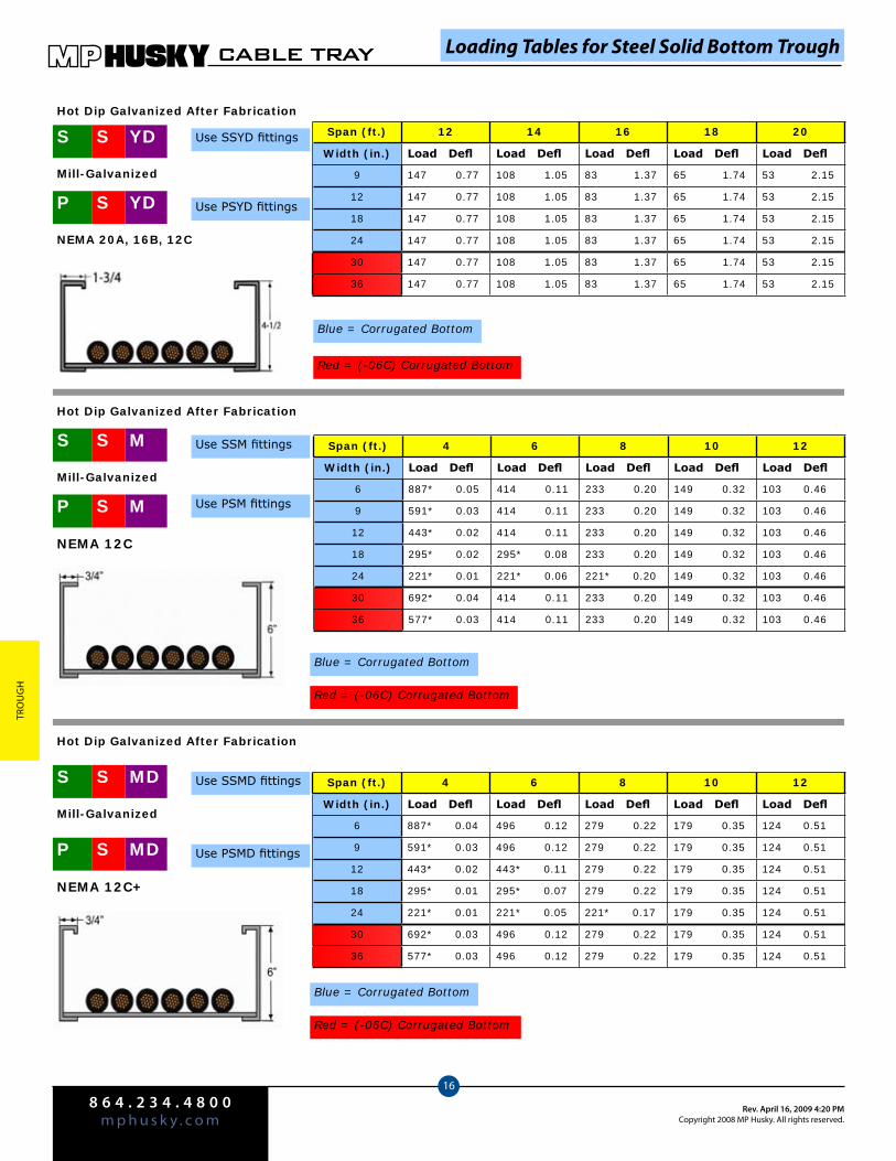
8 6 4 . 2 3 4 . 4 8 0 0m p h u s k y . c o m
Rev. April 16, 2009 4:20 PMCopyright 2008 MP Husky. All rights reserved.
CABLE TRAY
16
Tro
ug
H
Span (ft.) 12 14 16 18 20
Width (in.) Load Defl Load Defl Load Defl Load Defl Load Defl
9 147 0.77 108 1.05 83 1.37 65 1.74 53 2.15
12 147 0.77 108 1.05 83 1.37 65 1.74 53 2.15
18 147 0.77 108 1.05 83 1.37 65 1.74 53 2.15
24 147 0.77 108 1.05 83 1.37 65 1.74 53 2.15
30 147 0.77 108 1.05 83 1.37 65 1.74 53 2.15
36 147 0.77 108 1.05 83 1.37 65 1.74 53 2.15
NEMA 20A, 16B, 12C
Loading Tables for Steel Solid Bottom Trough
P YDS
Use SSYD fittingsS YDS
Hot Dip Galvanized After Fabrication
Mill-Galvanized
Use PSYD fittings
Blue = Corrugated Bottom
Red = (-06C) Corrugated Bottom
Span (ft.) 4 6 8 10 12
Width (in.) Load Defl Load Defl Load Defl Load Defl Load Defl
6 887* 0.05 414 0.11 233 0.20 149 0.32 103 0.46
9 591* 0.03 414 0.11 233 0.20 149 0.32 103 0.46
12 443* 0.02 414 0.11 233 0.20 149 0.32 103 0.46
18 295* 0.02 295* 0.08 233 0.20 149 0.32 103 0.46
24 221* 0.01 221* 0.06 221* 0.20 149 0.32 103 0.46
30 692* 0.04 414 0.11 233 0.20 149 0.32 103 0.46
36 577* 0.03 414 0.11 233 0.20 149 0.32 103 0.46
NEMA 12C
P MS
Use SSM fittingsS MS
Hot Dip Galvanized After Fabrication
Mill-Galvanized
Use PSM fittings
Blue = Corrugated Bottom
Red = (-06C) Corrugated Bottom
Span (ft.) 4 6 8 10 12
Width (in.) Load Defl Load Defl Load Defl Load Defl Load Defl
6 887* 0.04 496 0.12 279 0.22 179 0.35 124 0.51
9 591* 0.03 496 0.12 279 0.22 179 0.35 124 0.51
12 443* 0.02 443* 0.11 279 0.22 179 0.35 124 0.51
18 295* 0.01 295* 0.07 279 0.22 179 0.35 124 0.51
24 221* 0.01 221* 0.05 221* 0.17 179 0.35 124 0.51
30 692* 0.03 496 0.12 279 0.22 179 0.35 124 0.51
36 577* 0.03 496 0.12 279 0.22 179 0.35 124 0.51
NEMA 12C+
P MDS
Use SSMD fittingsS MDS
Hot Dip Galvanized After Fabrication
Mill-Galvanized
Use PSMD fittings
Blue = Corrugated Bottom
Red = (-06C) Corrugated Bottom
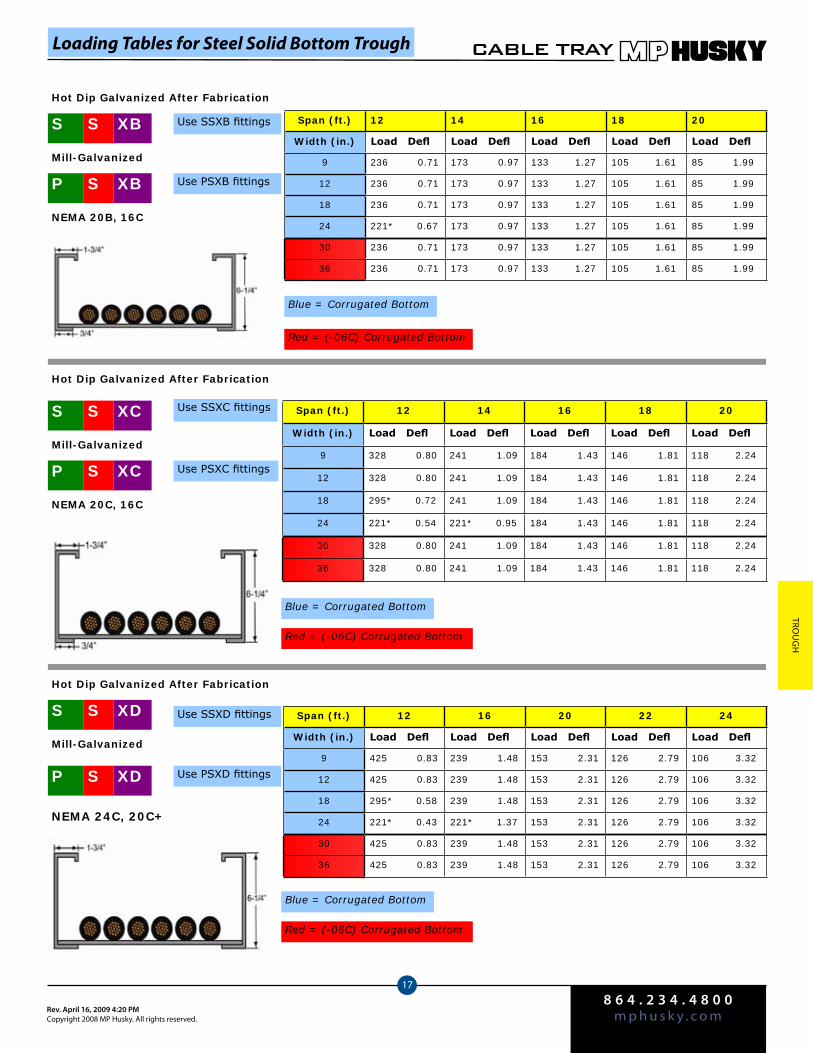
8 6 4 . 2 3 4 . 4 8 0 0m p h u s k y . c o mRev. April 16, 2009 4:20 PM
Copyright 2008 MP Husky. All rights reserved.
CABLE TRAY
17
Trou
gH
Span (ft.) 12 14 16 18 20
Width (in.) Load Defl Load Defl Load Defl Load Defl Load Defl
9 236 0.71 173 0.97 133 1.27 105 1.61 85 1.99
12 236 0.71 173 0.97 133 1.27 105 1.61 85 1.99
18 236 0.71 173 0.97 133 1.27 105 1.61 85 1.99
24 221* 0.67 173 0.97 133 1.27 105 1.61 85 1.99
30 236 0.71 173 0.97 133 1.27 105 1.61 85 1.99
36 236 0.71 173 0.97 133 1.27 105 1.61 85 1.99
Span (ft.) 12 14 16 18 20
Width (in.) Load Defl Load Defl Load Defl Load Defl Load Defl
9 328 0.80 241 1.09 184 1.43 146 1.81 118 2.24
12 328 0.80 241 1.09 184 1.43 146 1.81 118 2.24
18 295* 0.72 241 1.09 184 1.43 146 1.81 118 2.24
24 221* 0.54 221* 0.95 184 1.43 146 1.81 118 2.24
30 328 0.80 241 1.09 184 1.43 146 1.81 118 2.24
36 328 0.80 241 1.09 184 1.43 146 1.81 118 2.24
Span (ft.) 12 16 20 22 24
Width (in.) Load Defl Load Defl Load Defl Load Defl Load Defl
9 425 0.83 239 1.48 153 2.31 126 2.79 106 3.32
12 425 0.83 239 1.48 153 2.31 126 2.79 106 3.32
18 295* 0.58 239 1.48 153 2.31 126 2.79 106 3.32
24 221* 0.43 221* 1.37 153 2.31 126 2.79 106 3.32
30 425 0.83 239 1.48 153 2.31 126 2.79 106 3.32
36 425 0.83 239 1.48 153 2.31 126 2.79 106 3.32
NEMA 20B, 16C
NEMA 20C, 16C
NEMA 24C, 20C+
P XBS
Use SSXB fittingsS XBS
Mill-Galvanized
Use PSXB fittings
Blue = Corrugated Bottom
Red = (-06C) Corrugated Bottom
P XCS
Use SSXC fittingsS XCS
Mill-Galvanized
Use PSXC fittings
Blue = Corrugated Bottom
Red = (-06C) Corrugated Bottom
P XDS
Use SSXD fittingsS XDS
Mill-Galvanized
Use PSXD fittings
Blue = Corrugated Bottom
Red = (-06C) Corrugated Bottom
Hot Dip Galvanized After Fabrication
Hot Dip Galvanized After Fabrication
Hot Dip Galvanized After Fabrication
Loading Tables for Steel Solid Bottom Trough
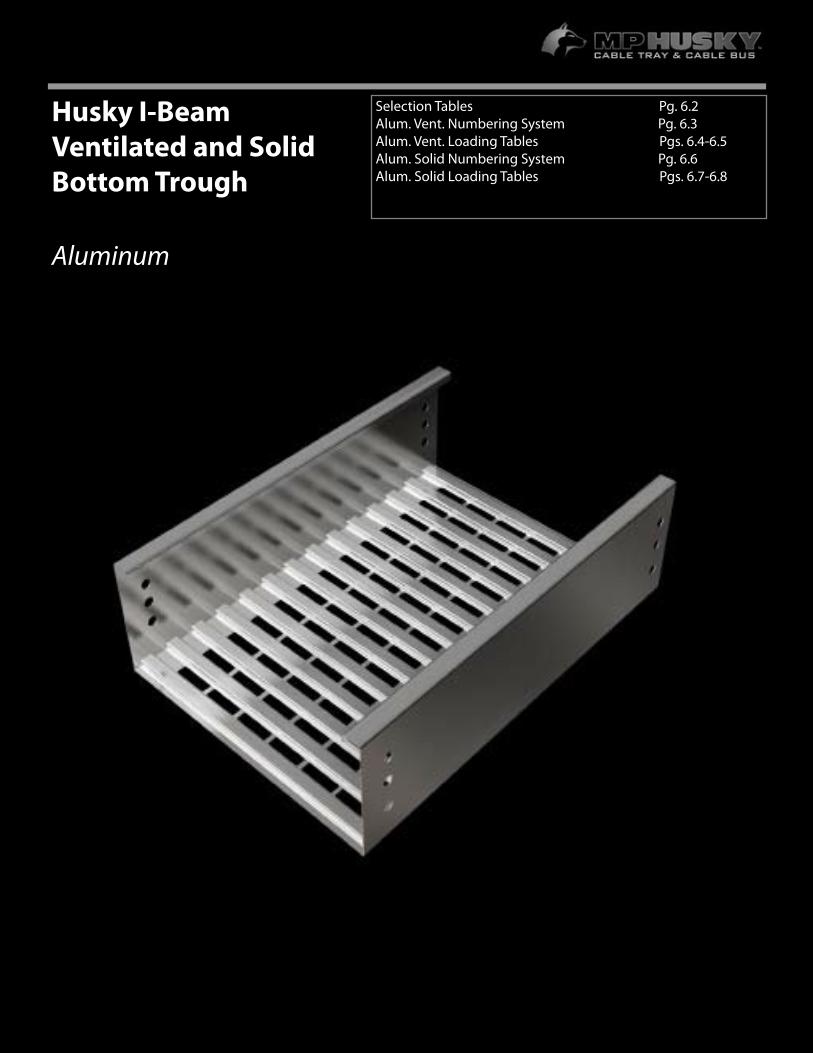
6.1
For more information or to order, call 1-800-277-4810 or visit www.mphusky.com.
Husky I-Beam Ventilated and Solid Bottom Trough
Aluminum
Selection Tables Pg. 6.2 Alum. Vent. Numbering System Pg. 6.3Alum. Vent. Loading Tables Pgs. 6.4-6.5Alum. Solid Numbering System Pg. 6.6Alum. Solid Loading Tables Pgs. 6.7-6.8 44.8
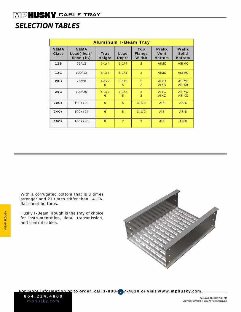
8 6 4 . 2 3 4 . 4 8 0 0m p h u s k y . c o m
Rev. April 16, 2009 4:24 PMCopyright 2008 MP Husky. All rights reserved.
CABLE TRAY
2
I-BeA
M T
rou
gH
For more information or to order, call 1-800-277-4810 or visit www.mphusky.com.
SELECTION TABLES
NEMAClass
NEMALoad(lbs.)/Span (ft.)
TrayHeight
LoadDepth
Top FlangeWidth
PrefixVent
Bottom
PrefixSolid
Bottom
12B 75/12 6-1/4 5-1/4 2 AIMC ASIMC
12C 100/12 6-1/4 5-1/4 2 AIMC ASIMC
20B 75/20 4-1/26
3-1/25
22
AIYCAIXB
ASIYCASIXB
20C 100/20 4-1/26
3-1/25
22
AIYCAIXC
ASIYCASIXC
20C+ 100+/20 6 5 3-1/2 AI6 ASI6
24C+ 100+/24 6 5 3-1/2 AI6 ASI6
30C+ 100+/30 8 7 3 AI8 ASI8
Aluminum I-Beam Tray
With a corrugated bottom that is 3 times stronger and 21 times stiffer than 14 GA. flat sheet bottoms.
Husky I-Beam Trough is the tray of choice for instrumentation, data transmission, and control cables.
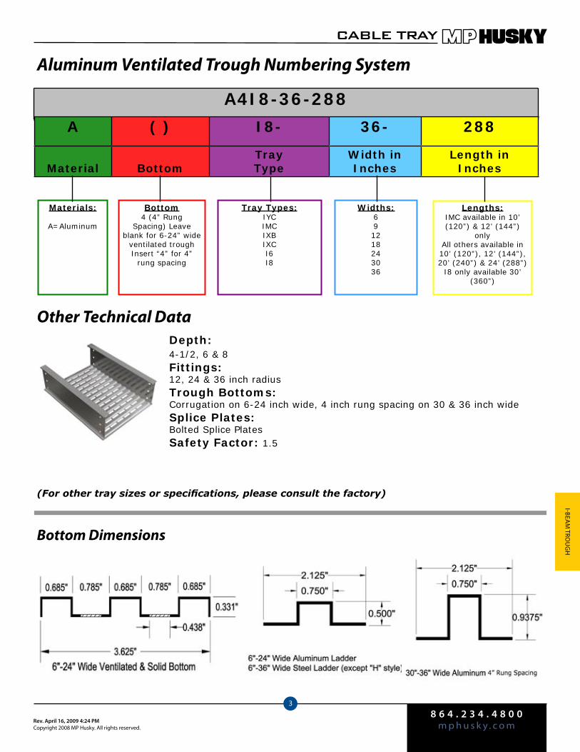
8 6 4 . 2 3 4 . 4 8 0 0m p h u s k y . c o mRev. April 16, 2009 4:24 PM
Copyright 2008 MP Husky. All rights reserved.
CABLE TRAY
3
I-BeAM
Trou
gH
A4I8-36-288
Aluminum Ventilated Trough Numbering System
Other Technical DataDepth:4-1/2, 6 & 8Fittings:12, 24 & 36 inch radiusTrough Bottoms:Corrugation on 6-24 inch wide, 4 inch rung spacing on 30 & 36 inch wideSplice Plates: Bolted Splice PlatesSafety Factor: 1.5
(For other tray sizes or specifications, please consult the factory)
Bottom Dimensions
Materials:
A=Aluminum
Bottom4 (4” Rung
Spacing) Leave blank for 6-24” wide
ventilated troughInsert “4” for 4”
rung spacing
Tray Types:IYCIMCIXBIXCI6I8
Widths:691218243036
Lengths:IMC available in 10’ (120”) & 12’ (144”)
onlyAll others available in 10’ (120”), 12’ (144”), 20’ (240”) & 24’ (288”)
I8 only available 30’ (360”)
A ( ) I8- 36- 288
Material BottomTray Type
Width in Inches
Length in Inches
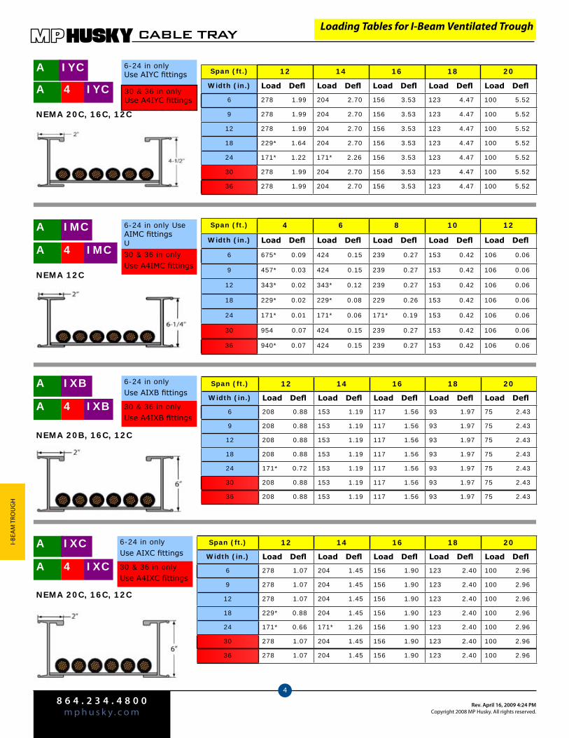
8 6 4 . 2 3 4 . 4 8 0 0m p h u s k y . c o m
Rev. April 16, 2009 4:24 PMCopyright 2008 MP Husky. All rights reserved.
CABLE TRAY
4
I-BeA
M T
rou
gH
Loading Tables for I-Beam Ventilated Trough
Span (ft.) 12 14 16 18 20
Width (in.) Load Defl Load Defl Load Defl Load Defl Load Defl
6 278 1.99 204 2.70 156 3.53 123 4.47 100 5.52
9 278 1.99 204 2.70 156 3.53 123 4.47 100 5.52
12 278 1.99 204 2.70 156 3.53 123 4.47 100 5.52
18 229* 1.64 204 2.70 156 3.53 123 4.47 100 5.52
24 171* 1.22 171* 2.26 156 3.53 123 4.47 100 5.52
30 278 1.99 204 2.70 156 3.53 123 4.47 100 5.52
36 278 1.99 204 2.70 156 3.53 123 4.47 100 5.52
A IYC4
NEMA 20C, 16C, 12C
A IYC 6-24 in onlyUse AIYC fittings
30 & 36 in onlyUse A4IYC fittings
A IMC4
NEMA 12C
Span (ft.) 4 6 8 10 12
Width (in.) Load Defl Load Defl Load Defl Load Defl Load Defl
6 675* 0.09 424 0.15 239 0.27 153 0.42 106 0.06
9 457* 0.03 424 0.15 239 0.27 153 0.42 106 0.06
12 343* 0.02 343* 0.12 239 0.27 153 0.42 106 0.06
18 229* 0.02 229* 0.08 229 0.26 153 0.42 106 0.06
24 171* 0.01 171* 0.06 171* 0.19 153 0.42 106 0.06
30 954 0.07 424 0.15 239 0.27 153 0.42 106 0.06
36 940* 0.07 424 0.15 239 0.27 153 0.42 106 0.06
A IMC 6-24 in only Use AIMC fittingsU
30 & 36 in onlyUse A4IMC fittings
Span (ft.) 12 14 16 18 20
Width (in.) Load Defl Load Defl Load Defl Load Defl Load Defl
6 208 0.88 153 1.19 117 1.56 93 1.97 75 2.43
9 208 0.88 153 1.19 117 1.56 93 1.97 75 2.43
12 208 0.88 153 1.19 117 1.56 93 1.97 75 2.43
18 208 0.88 153 1.19 117 1.56 93 1.97 75 2.43
24 171* 0.72 153 1.19 117 1.56 93 1.97 75 2.43
30 208 0.88 153 1.19 117 1.56 93 1.97 75 2.43
36 208 0.88 153 1.19 117 1.56 93 1.97 75 2.43
A IXB4
NEMA 20B, 16C, 12C
6-24 in onlyUse AIXB fittings
30 & 36 in onlyUse A4IXB fittings
A IXB
A IXC4
NEMA 20C, 16C, 12C
6-24 in onlyUse AIXC fittings
30 & 36 in onlyUse A4IXC fittings
A IXC Span (ft.) 12 14 16 18 20
Width (in.) Load Defl Load Defl Load Defl Load Defl Load Defl
6 278 1.07 204 1.45 156 1.90 123 2.40 100 2.96
9 278 1.07 204 1.45 156 1.90 123 2.40 100 2.96
12 278 1.07 204 1.45 156 1.90 123 2.40 100 2.96
18 229* 0.88 204 1.45 156 1.90 123 2.40 100 2.96
24 171* 0.66 171* 1.26 156 1.90 123 2.40 100 2.96
30 278 1.07 204 1.45 156 1.90 123 2.40 100 2.96
36 278 1.07 204 1.45 156 1.90 123 2.40 100 2.96

8 6 4 . 2 3 4 . 4 8 0 0m p h u s k y . c o mRev. April 16, 2009 4:24 PM
Copyright 2008 MP Husky. All rights reserved.
CABLE TRAY
5
I-BeAM
Trou
gH
Part # A4I8-36-288
Span (ft.) 12 16 20 22 24
Width (in.) Load Defl Load Defl Load Defl Load Defl Load Defl
9 457* 1.36 277 2.25 177 3.52 146 4.26 123 5.07
12 343* 1.02 277 2.25 177 3.52 146 4.26 123 5.07
18 229* 0.68 229* 1.86 177 3.52 146 4.26 123 5.07
24 171* 0.01 171* 1.39 171* 3.40 146 4.26 123 5.07
30 492 1.26 277 2.25 177 3.52 146 4.26 123 5.07
36 492 1.26 277 2.25 177 3.52 146 4.26 123 5.07
A I6 Use AI6 fittings
NEMA 24C+, 20C+
Span (ft.) 12 16 20 24 30
Width (in.) Load Defl Load Defl Load Defl Load Defl Load Defl
9 457* 0.41 411 1.17 263 1.82 183 2.62 117 4.10
12 343* 0.31 343* 0.98 263 1.82 183 2.62 117 4.10
18 229* 0.21 229* 0.65 229* 1.59 183 2.62 117 4.10
24 171* 0.15 171* 0.49 171* 1.18 171* 2.45 117 4.10
30 732 0.66 411 1.17 263 1.82 183 2.62 117 4.10
36 722* 0.65 411 1.17 263 1.82 183 2.62 117 4.10
A I8 Use AI8 fittings
NEMA 30C+, 24C+
A 4 I6 Use A4I6 fittings
A 4 I8 Use A4I8 fittings
Loading Tables for I-Beam Ventilated Trough
Example:
USE COLOR CODING TO ASSEMBLE PART NUMBER
A ( ) I8- 36- 144
Tray Type
Bottom TrayType
Widthin Inches
Lenthin Inches
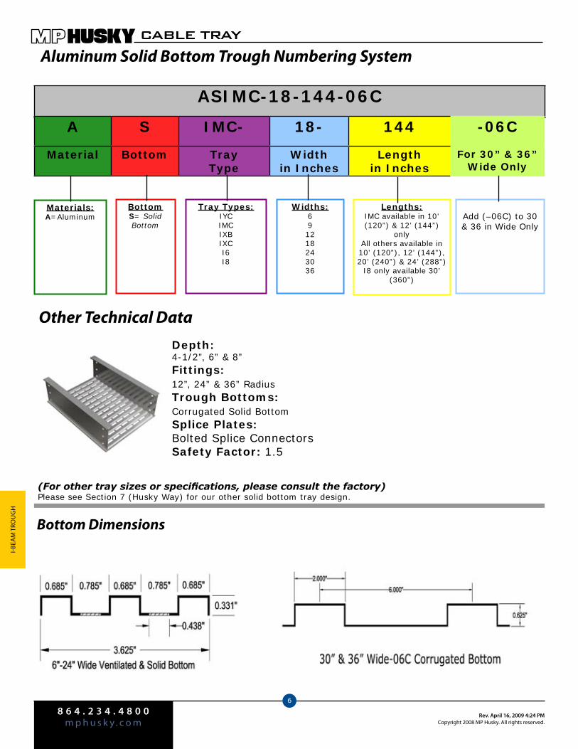
8 6 4 . 2 3 4 . 4 8 0 0m p h u s k y . c o m
Rev. April 16, 2009 4:24 PMCopyright 2008 MP Husky. All rights reserved.
CABLE TRAY
6
I-BeA
M T
rou
gH
ASIMC-18-144-06C
Aluminum Solid Bottom Trough Numbering System
Other Technical DataDepth:4-1/2”, 6” & 8”Fittings:12”, 24” & 36” RadiusTrough Bottoms:Corrugated Solid BottomSplice Plates: Bolted Splice ConnectorsSafety Factor: 1.5
(For other tray sizes or specifications, please consult the factory)Please see Section 7 (Husky Way) for our other solid bottom tray design.
Bottom Dimensions
A S IMC- 18- 144 -06C
Material Bottom TrayType
Widthin Inches
Length in Inches
For 30” & 36”Wide Only
Materials:A=Aluminum
BottomS= Solid Bottom
Tray Types:IYCIMCIXBIXCI6I8
Widths:691218243036
Lengths:IMC available in 10’ (120”) & 12’ (144”)
onlyAll others available in 10’ (120”), 12’ (144”), 20’ (240”) & 24’ (288”)
I8 only available 30’ (360”)
Add (–06C) to 30 & 36 in Wide Only
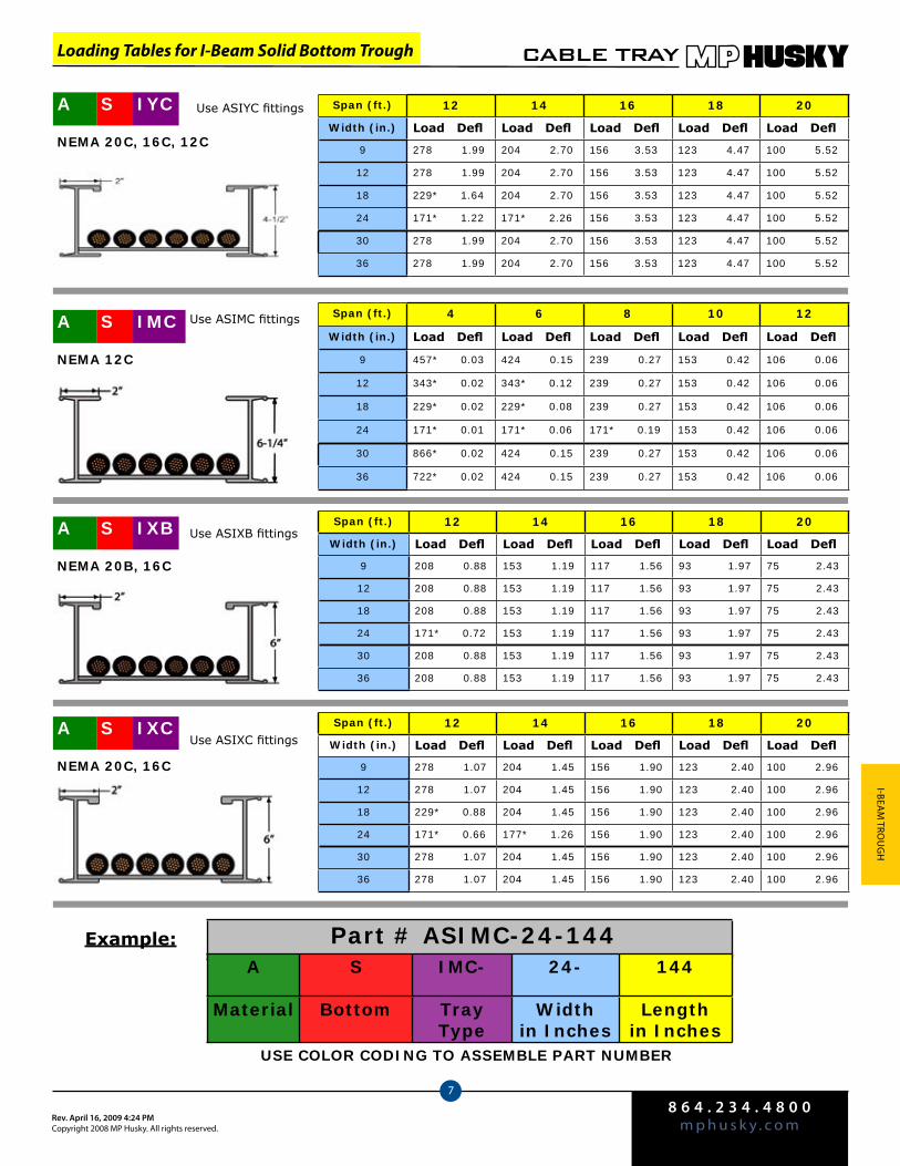
8 6 4 . 2 3 4 . 4 8 0 0m p h u s k y . c o mRev. April 16, 2009 4:24 PM
Copyright 2008 MP Husky. All rights reserved.
CABLE TRAY
7
I-BeAM
Trou
gH
Loading Tables for I-Beam Solid Bottom Trough
Example: Part # ASIMC-24-144A S IMC- 24- 144
Material Bottom TrayType
Widthin Inches
Lengthin Inches
USE COLOR CODING TO ASSEMBLE PART NUMBER
Span (ft.) 12 14 16 18 20
Width (in.) Load Defl Load Defl Load Defl Load Defl Load Defl
9 278 1.99 204 2.70 156 3.53 123 4.47 100 5.52
12 278 1.99 204 2.70 156 3.53 123 4.47 100 5.52
18 229* 1.64 204 2.70 156 3.53 123 4.47 100 5.52
24 171* 1.22 171* 2.26 156 3.53 123 4.47 100 5.52
30 278 1.99 204 2.70 156 3.53 123 4.47 100 5.52
36 278 1.99 204 2.70 156 3.53 123 4.47 100 5.52
A IYCS
NEMA 20C, 16C, 12C
Use ASIYC fittings
A IMCS
NEMA 12C
Span (ft.) 4 6 8 10 12
Width (in.) Load Defl Load Defl Load Defl Load Defl Load Defl
9 457* 0.03 424 0.15 239 0.27 153 0.42 106 0.06
12 343* 0.02 343* 0.12 239 0.27 153 0.42 106 0.06
18 229* 0.02 229* 0.08 239 0.27 153 0.42 106 0.06
24 171* 0.01 171* 0.06 171* 0.19 153 0.42 106 0.06
30 866* 0.02 424 0.15 239 0.27 153 0.42 106 0.06
36 722* 0.02 424 0.15 239 0.27 153 0.42 106 0.06
Use ASIMC fittings
A IXBS
NEMA 20B, 16C
Use ASIXB fittingsSpan (ft.) 12 14 16 18 20
Width (in.) Load Defl Load Defl Load Defl Load Defl Load Defl
9 208 0.88 153 1.19 117 1.56 93 1.97 75 2.43
12 208 0.88 153 1.19 117 1.56 93 1.97 75 2.43
18 208 0.88 153 1.19 117 1.56 93 1.97 75 2.43
24 171* 0.72 153 1.19 117 1.56 93 1.97 75 2.43
30 208 0.88 153 1.19 117 1.56 93 1.97 75 2.43
36 208 0.88 153 1.19 117 1.56 93 1.97 75 2.43
Span (ft.) 12 14 16 18 20
Width (in.) Load Defl Load Defl Load Defl Load Defl Load Defl
9 278 1.07 204 1.45 156 1.90 123 2.40 100 2.96
12 278 1.07 204 1.45 156 1.90 123 2.40 100 2.96
18 229* 0.88 204 1.45 156 1.90 123 2.40 100 2.96
24 171* 0.66 177* 1.26 156 1.90 123 2.40 100 2.96
30 278 1.07 204 1.45 156 1.90 123 2.40 100 2.96
36 278 1.07 204 1.45 156 1.90 123 2.40 100 2.96
A IXCS
NEMA 20C, 16C
Use ASIXC fittings
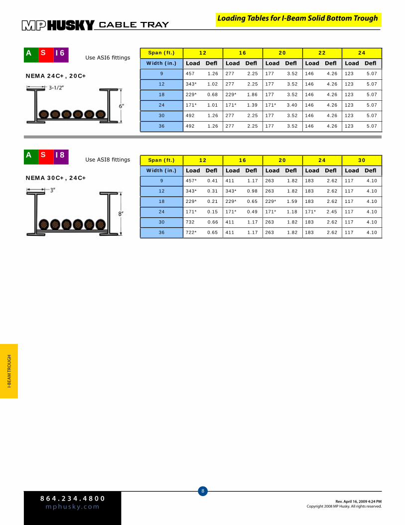
8 6 4 . 2 3 4 . 4 8 0 0m p h u s k y . c o m
Rev. April 16, 2009 4:24 PMCopyright 2008 MP Husky. All rights reserved.
CABLE TRAY
8
I-BeA
M T
rou
gH
Loading Tables for I-Beam Solid Bottom Trough
Span (ft.) 12 16 20 22 24
Width (in.) Load Defl Load Defl Load Defl Load Defl Load Defl
9 457 1.26 277 2.25 177 3.52 146 4.26 123 5.07
12 343* 1.02 277 2.25 177 3.52 146 4.26 123 5.07
18 229* 0.68 229* 1.86 177 3.52 146 4.26 123 5.07
24 171* 1.01 171* 1.39 171* 3.40 146 4.26 123 5.07
30 492 1.26 277 2.25 177 3.52 146 4.26 123 5.07
36 492 1.26 277 2.25 177 3.52 146 4.26 123 5.07
A S I6Use ASI6 fittings
NEMA 24C+, 20C+
Span (ft.) 12 16 20 24 30
Width (in.) Load Defl Load Defl Load Defl Load Defl Load Defl
9 457* 0.41 411 1.17 263 1.82 183 2.62 117 4.10
12 343* 0.31 343* 0.98 263 1.82 183 2.62 117 4.10
18 229* 0.21 229* 0.65 229* 1.59 183 2.62 117 4.10
24 171* 0.15 171* 0.49 171* 1.18 171* 2.45 117 4.10
30 732 0.66 411 1.17 263 1.82 183 2.62 117 4.10
36 722* 0.65 411 1.17 263 1.82 183 2.62 117 4.10
A S I8Use ASI8 fittings
NEMA 30C+, 24C+
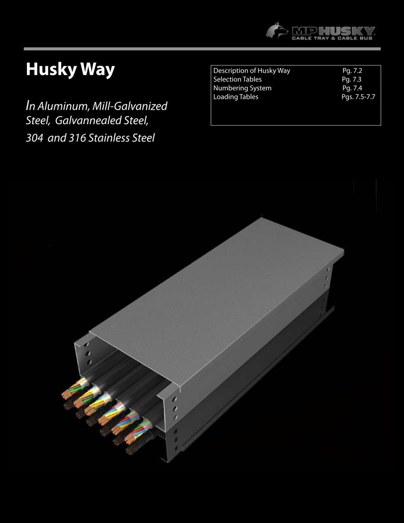
7.1
Husky Way
In Aluminum, Mill-Galvanized Steel, Galvannealed Steel, 304 and 316 Stainless Steel
Description of Husky Way Pg. 7.2Selection Tables Pg. 7.3Numbering System Pg. 7.4 Loading Tables Pgs. 7.5-7.7
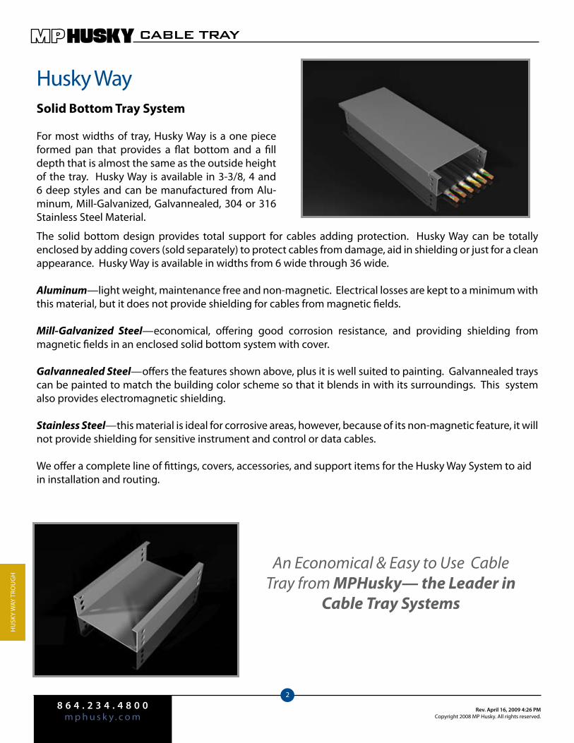
8 6 4 . 2 3 4 . 4 8 0 0m p h u s k y . c o m
Rev. April 16, 2009 4:26 PMCopyright 2008 MP Husky. All rights reserved.
CABLE TRAY
2
Hu
Sky
WAy
Tro
ug
H
The solid bottom design provides total support for cables adding protection. Husky Way can be totally enclosed by adding covers (sold separately) to protect cables from damage, aid in shielding or just for a clean appearance. Husky Way is available in widths from 6 wide through 36 wide.
Aluminum—light weight, maintenance free and non-magnetic. Electrical losses are kept to a minimum with this material, but it does not provide shielding for cables from magnetic fields.
Mill-Galvanized Steel—economical, offering good corrosion resistance, and providing shielding from magnetic fields in an enclosed solid bottom system with cover.
Galvannealed Steel—offers the features shown above, plus it is well suited to painting. galvannealed trays can be painted to match the building color scheme so that it blends in with its surroundings. This system also provides electromagnetic shielding.
Stainless Steel—this material is ideal for corrosive areas, however, because of its non-magnetic feature, it will not provide shielding for sensitive instrument and control or data cables.
We offer a complete line of fittings, covers, accessories, and support items for the Husky Way System to aid in installation and routing.
An Economical & Easy to Use Cable Tray from MPHusky— the Leader in
Cable Tray Systems
Husky WaySolid Bottom Tray System
For most widths of tray, Husky Way is a one piece formed pan that provides a flat bottom and a fill depth that is almost the same as the outside height of the tray. Husky Way is available in 3-3/8, 4 and 6 deep styles and can be manufactured from Alu-minum, Mill-galvanized, galvannealed, 304 or 316 Stainless Steel Material.
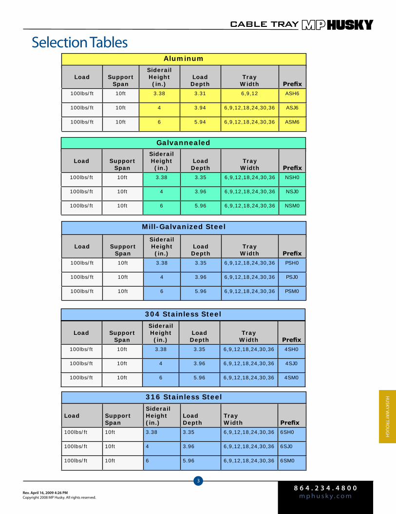
8 6 4 . 2 3 4 . 4 8 0 0m p h u s k y . c o mRev. April 16, 2009 4:26 PM
Copyright 2008 MP Husky. All rights reserved.
CABLE TRAY
3
Hu
Sky WAy Tro
ug
H
Aluminum
Mill-Galvanized Steel
Selection Tables
Galvannealed
304 Stainless Steel
316 Stainless Steel
Load SupportSpan
SiderailHeight(in.)
LoadDepth
TrayWidth Prefix
100lbs/ft 10ft 3.38 3.35 6,9,12,18,24,30,36 PSH0
100lbs/ft 10ft 4 3.96 6,9,12,18,24,30,36 PSJ0
100lbs/ft 10ft 6 5.96 6,9,12,18,24,30,36 PSM0
Load SupportSpan
SiderailHeight(in.)
LoadDepth
TrayWidth Prefix
100lbs/ft 10ft 3.38 3.35 6,9,12,18,24,30,36 4SH0
100lbs/ft 10ft 4 3.96 6,9,12,18,24,30,36 4SJ0
100lbs/ft 10ft 6 5.96 6,9,12,18,24,30,36 4SM0
Load SupportSpan
SiderailHeight(in.)
LoadDepth
TrayWidth Prefix
100lbs/ft 10ft 3.38 3.35 6,9,12,18,24,30,36 6SH0
100lbs/ft 10ft 4 3.96 6,9,12,18,24,30,36 6SJ0
100lbs/ft 10ft 6 5.96 6,9,12,18,24,30,36 6SM0
Load SupportSpan
SiderailHeight (in.)
LoadDepth
TrayWidth Prefix
100lbs/ft 10ft 3.38 3.35 6,9,12,18,24,30,36 NSH0
100lbs/ft 10ft 4 3.96 6,9,12,18,24,30,36 NSJ0
100lbs/ft 10ft 6 5.96 6,9,12,18,24,30,36 NSM0
Load SupportSpan
SiderailHeight (in.)
LoadDepth
TrayWidth Prefix
100lbs/ft 10ft 3.38 3.31 6,9,12 ASH6
100lbs/ft 10ft 4 3.94 6,9,12,18,24,30,36 ASJ6
100lbs/ft 10ft 6 5.94 6,9,12,18,24,30,36 ASM6
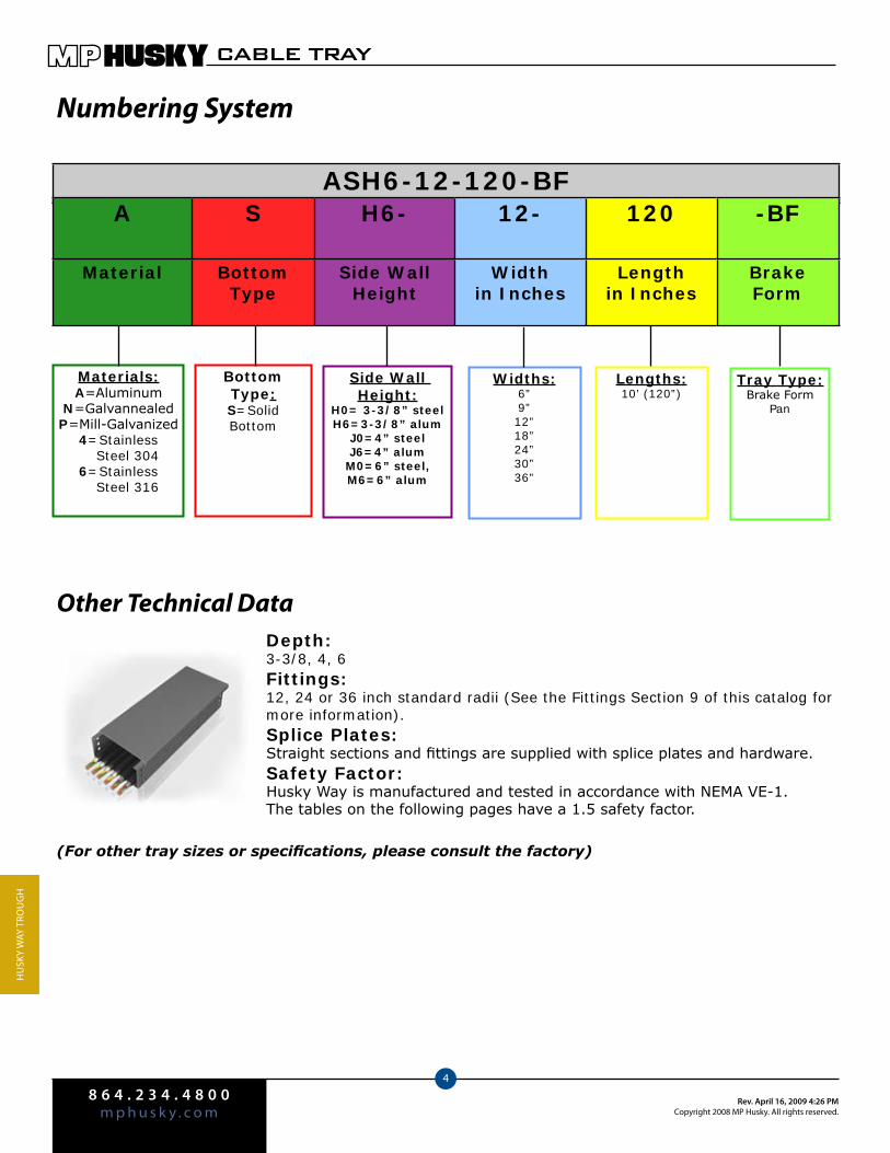
8 6 4 . 2 3 4 . 4 8 0 0m p h u s k y . c o m
Rev. April 16, 2009 4:26 PMCopyright 2008 MP Husky. All rights reserved.
CABLE TRAY
4
Hu
Sky
WAy
Tro
ug
H
Other Technical DataDepth: 3-3/8, 4, 6Fittings:12, 24 or 36 inch standard radii (See the Fittings Section 9 of this catalog for more information).Splice Plates:Straight sections and fittings are supplied with splice plates and hardware.Safety Factor:Husky Way is manufactured and tested in accordance with NEMA VE-1. The tables on the following pages have a 1.5 safety factor.
(For other tray sizes or specifications, please consult the factory)
ASH6-12-120-BF
Materials:A=Aluminum
N=GalvannealedP=Mill-Galvanized
4=Stainless Steel 3046=Stainless Steel 316
Bottom Type:S=Solid Bottom
Side Wall Height:
H0= 3-3/8” steelH6=3-3/8” alum
J0=4” steelJ6=4” alum
M0=6” steel, M6=6” alum
Widths:6”9”12”18”24”30”36”
Lengths:10’ (120”)
Numbering System
Tray Type:Brake Form
Pan
A S H6- 12- 120 -BF
Material BottomType
Side WallHeight
Widthin Inches
Lengthin Inches
BrakeForm
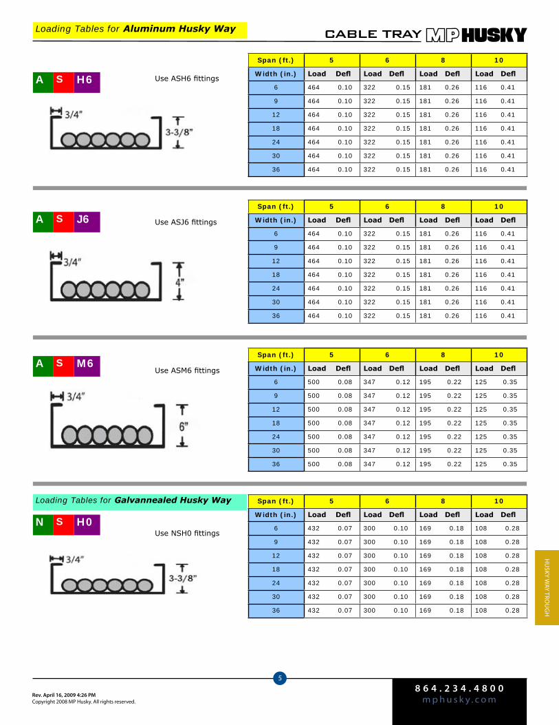
8 6 4 . 2 3 4 . 4 8 0 0m p h u s k y . c o mRev. April 16, 2009 4:26 PM
Copyright 2008 MP Husky. All rights reserved.
CABLE TRAY
5
Hu
Sky WAy Tro
ug
H
Loading Tables for Aluminum Husky Way
Span (ft.) 5 6 8 10
Width (in.) Load Defl Load Defl Load Defl Load Defl
6 464 0.10 322 0.15 181 0.26 116 0.41
9 464 0.10 322 0.15 181 0.26 116 0.41
12 464 0.10 322 0.15 181 0.26 116 0.41
18 464 0.10 322 0.15 181 0.26 116 0.41
24 464 0.10 322 0.15 181 0.26 116 0.41
30 464 0.10 322 0.15 181 0.26 116 0.41
36 464 0.10 322 0.15 181 0.26 116 0.41
A M6S
A J6S
A H6S Use ASH6 fittings
Span (ft.) 5 6 8 10
Width (in.) Load Defl Load Defl Load Defl Load Defl
6 464 0.10 322 0.15 181 0.26 116 0.41
9 464 0.10 322 0.15 181 0.26 116 0.41
12 464 0.10 322 0.15 181 0.26 116 0.41
18 464 0.10 322 0.15 181 0.26 116 0.41
24 464 0.10 322 0.15 181 0.26 116 0.41
30 464 0.10 322 0.15 181 0.26 116 0.41
36 464 0.10 322 0.15 181 0.26 116 0.41
Span (ft.) 5 6 8 10
Width (in.) Load Defl Load Defl Load Defl Load Defl
6 500 0.08 347 0.12 195 0.22 125 0.35
9 500 0.08 347 0.12 195 0.22 125 0.35
12 500 0.08 347 0.12 195 0.22 125 0.35
18 500 0.08 347 0.12 195 0.22 125 0.35
24 500 0.08 347 0.12 195 0.22 125 0.35
30 500 0.08 347 0.12 195 0.22 125 0.35
36 500 0.08 347 0.12 195 0.22 125 0.35
Use ASJ6 fittings
Use ASM6 fittings
N H0S
Span (ft.) 5 6 8 10
Width (in.) Load Defl Load Defl Load Defl Load Defl
6 432 0.07 300 0.10 169 0.18 108 0.28
9 432 0.07 300 0.10 169 0.18 108 0.28
12 432 0.07 300 0.10 169 0.18 108 0.28
18 432 0.07 300 0.10 169 0.18 108 0.28
24 432 0.07 300 0.10 169 0.18 108 0.28
30 432 0.07 300 0.10 169 0.18 108 0.28
36 432 0.07 300 0.10 169 0.18 108 0.28
Loading Tables for Galvannealed Husky Way
Use NSH0 fittings
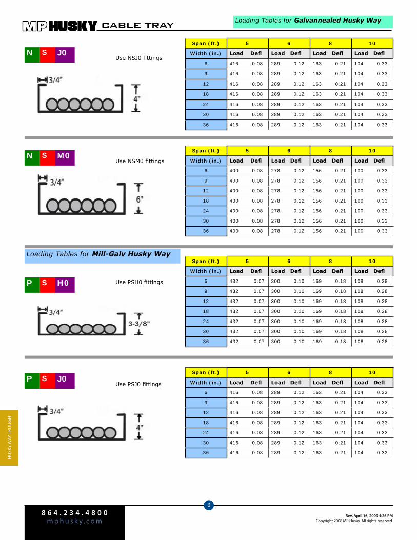
8 6 4 . 2 3 4 . 4 8 0 0m p h u s k y . c o m
Rev. April 16, 2009 4:26 PMCopyright 2008 MP Husky. All rights reserved.
CABLE TRAY
6
Hu
Sky
WAy
Tro
ug
H
Span (ft.) 5 6 8 10
Width (in.) Load Defl Load Defl Load Defl Load Defl
6 400 0.08 278 0.12 156 0.21 100 0.33
9 400 0.08 278 0.12 156 0.21 100 0.33
12 400 0.08 278 0.12 156 0.21 100 0.33
18 400 0.08 278 0.12 156 0.21 100 0.33
24 400 0.08 278 0.12 156 0.21 100 0.33
30 400 0.08 278 0.12 156 0.21 100 0.33
36 400 0.08 278 0.12 156 0.21 100 0.33
N M0S Use NSM0 fittings
Loading Tables for Galvannealed Husky Way
Span (ft.) 5 6 8 10
Width (in.) Load Defl Load Defl Load Defl Load Defl
6 416 0.08 289 0.12 163 0.21 104 0.33
9 416 0.08 289 0.12 163 0.21 104 0.33
12 416 0.08 289 0.12 163 0.21 104 0.33
18 416 0.08 289 0.12 163 0.21 104 0.33
24 416 0.08 289 0.12 163 0.21 104 0.33
30 416 0.08 289 0.12 163 0.21 104 0.33
36 416 0.08 289 0.12 163 0.21 104 0.33
P J0SUse PSJ0 fittings
Span (ft.) 5 6 8 10
Width (in.) Load Defl Load Defl Load Defl Load Defl
6 432 0.07 300 0.10 169 0.18 108 0.28
9 432 0.07 300 0.10 169 0.18 108 0.28
12 432 0.07 300 0.10 169 0.18 108 0.28
18 432 0.07 300 0.10 169 0.18 108 0.28
24 432 0.07 300 0.10 169 0.18 108 0.28
30 432 0.07 300 0.10 169 0.18 108 0.28
36 432 0.07 300 0.10 169 0.18 108 0.28
Loading Tables for Mill-Galv Husky Way
P H0S Use PSH0 fittings
Span (ft.) 5 6 8 10
Width (in.) Load Defl Load Defl Load Defl Load Defl
6 416 0.08 289 0.12 163 0.21 104 0.33
9 416 0.08 289 0.12 163 0.21 104 0.33
12 416 0.08 289 0.12 163 0.21 104 0.33
18 416 0.08 289 0.12 163 0.21 104 0.33
24 416 0.08 289 0.12 163 0.21 104 0.33
30 416 0.08 289 0.12 163 0.21 104 0.33
36 416 0.08 289 0.12 163 0.21 104 0.33
N J0SUse NSJ0 fittings
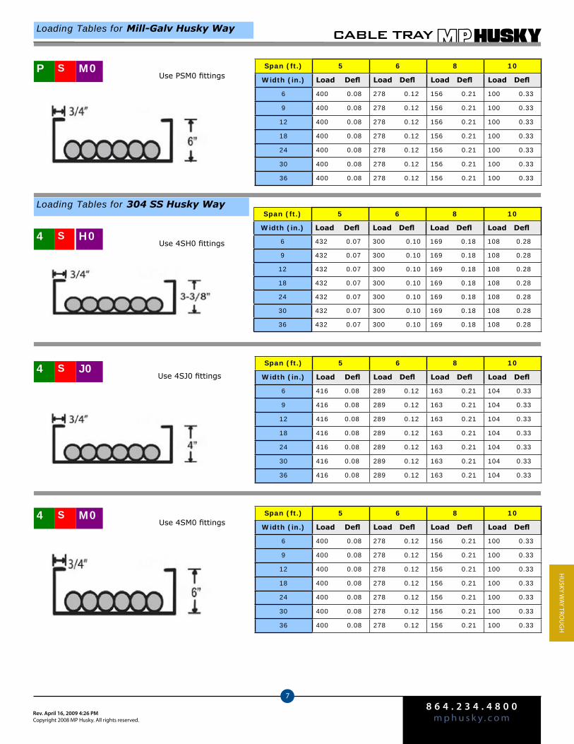
8 6 4 . 2 3 4 . 4 8 0 0m p h u s k y . c o mRev. April 16, 2009 4:26 PM
Copyright 2008 MP Husky. All rights reserved.
CABLE TRAY
7
Hu
Sky WAy Tro
ug
H
4 J0SSpan (ft.) 5 6 8 10
Width (in.) Load Defl Load Defl Load Defl Load Defl
6 416 0.08 289 0.12 163 0.21 104 0.33
9 416 0.08 289 0.12 163 0.21 104 0.33
12 416 0.08 289 0.12 163 0.21 104 0.33
18 416 0.08 289 0.12 163 0.21 104 0.33
24 416 0.08 289 0.12 163 0.21 104 0.33
30 416 0.08 289 0.12 163 0.21 104 0.33
36 416 0.08 289 0.12 163 0.21 104 0.33
Span (ft.) 5 6 8 10
Width (in.) Load Defl Load Defl Load Defl Load Defl
6 400 0.08 278 0.12 156 0.21 100 0.33
9 400 0.08 278 0.12 156 0.21 100 0.33
12 400 0.08 278 0.12 156 0.21 100 0.33
18 400 0.08 278 0.12 156 0.21 100 0.33
24 400 0.08 278 0.12 156 0.21 100 0.33
30 400 0.08 278 0.12 156 0.21 100 0.33
36 400 0.08 278 0.12 156 0.21 100 0.33
4 M0S
Use 4SJ0 fittings
Use 4SM0 fittings
Loading Tables for Mill-Galv Husky Way
4 H0S
Loading Tables for 304 SS Husky Way Span (ft.) 5 6 8 10
Width (in.) Load Defl Load Defl Load Defl Load Defl
6 432 0.07 300 0.10 169 0.18 108 0.28
9 432 0.07 300 0.10 169 0.18 108 0.28
12 432 0.07 300 0.10 169 0.18 108 0.28
18 432 0.07 300 0.10 169 0.18 108 0.28
24 432 0.07 300 0.10 169 0.18 108 0.28
30 432 0.07 300 0.10 169 0.18 108 0.28
36 432 0.07 300 0.10 169 0.18 108 0.28
Use 4SH0 fittings
Span (ft.) 5 6 8 10
Width (in.) Load Defl Load Defl Load Defl Load Defl
6 400 0.08 278 0.12 156 0.21 100 0.33
9 400 0.08 278 0.12 156 0.21 100 0.33
12 400 0.08 278 0.12 156 0.21 100 0.33
18 400 0.08 278 0.12 156 0.21 100 0.33
24 400 0.08 278 0.12 156 0.21 100 0.33
30 400 0.08 278 0.12 156 0.21 100 0.33
36 400 0.08 278 0.12 156 0.21 100 0.33
P M0SUse PSM0 fittings
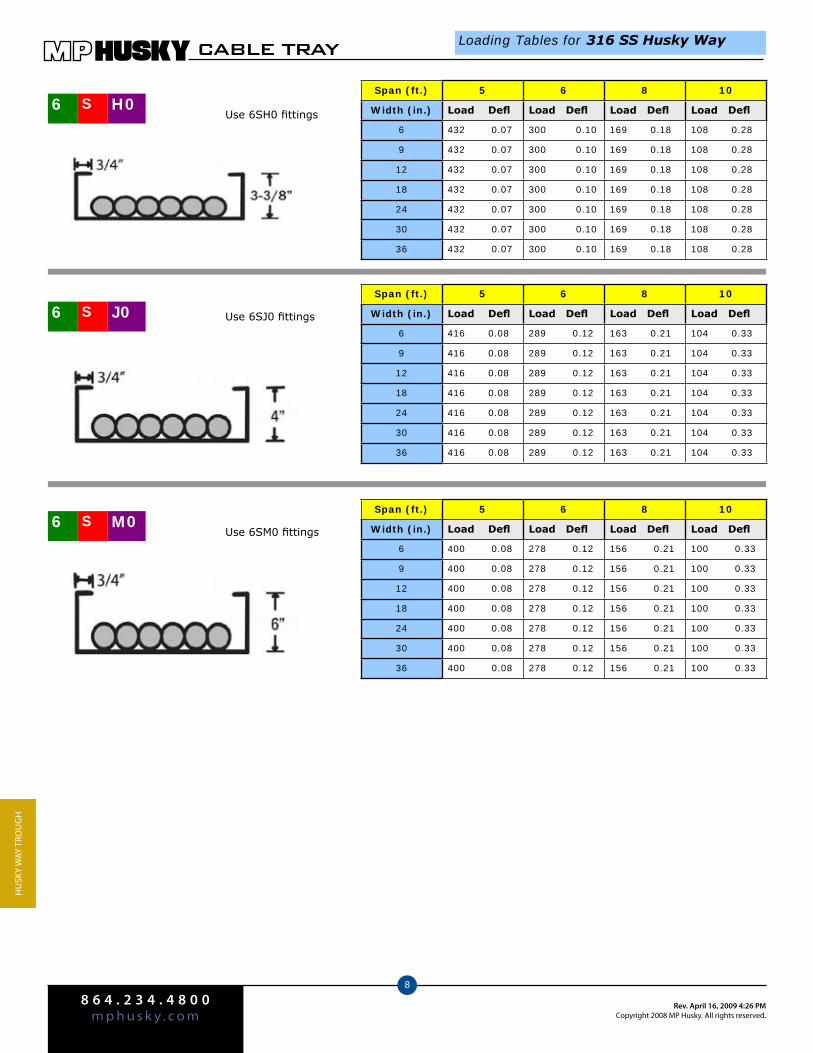
8 6 4 . 2 3 4 . 4 8 0 0m p h u s k y . c o m
Rev. April 16, 2009 4:26 PMCopyright 2008 MP Husky. All rights reserved.
CABLE TRAY
8
Hu
Sky
WAy
Tro
ug
H
Span (ft.) 5 6 8 10
Width (in.) Load Defl Load Defl Load Defl Load Defl
6 432 0.07 300 0.10 169 0.18 108 0.28
9 432 0.07 300 0.10 169 0.18 108 0.28
12 432 0.07 300 0.10 169 0.18 108 0.28
18 432 0.07 300 0.10 169 0.18 108 0.28
24 432 0.07 300 0.10 169 0.18 108 0.28
30 432 0.07 300 0.10 169 0.18 108 0.28
36 432 0.07 300 0.10 169 0.18 108 0.28
Loading Tables for 316 SS Husky Way
6 H0S Use 6SH0 fittings
Span (ft.) 5 6 8 10
Width (in.) Load Defl Load Defl Load Defl Load Defl
6 416 0.08 289 0.12 163 0.21 104 0.33
9 416 0.08 289 0.12 163 0.21 104 0.33
12 416 0.08 289 0.12 163 0.21 104 0.33
18 416 0.08 289 0.12 163 0.21 104 0.33
24 416 0.08 289 0.12 163 0.21 104 0.33
30 416 0.08 289 0.12 163 0.21 104 0.33
36 416 0.08 289 0.12 163 0.21 104 0.33
6 M0S
6 J0S
Span (ft.) 5 6 8 10
Width (in.) Load Defl Load Defl Load Defl Load Defl
6 400 0.08 278 0.12 156 0.21 100 0.33
9 400 0.08 278 0.12 156 0.21 100 0.33
12 400 0.08 278 0.12 156 0.21 100 0.33
18 400 0.08 278 0.12 156 0.21 100 0.33
24 400 0.08 278 0.12 156 0.21 100 0.33
30 400 0.08 278 0.12 156 0.21 100 0.33
36 400 0.08 278 0.12 156 0.21 100 0.33
Use 6SJ0 fittings
Use 6SM0 fittings
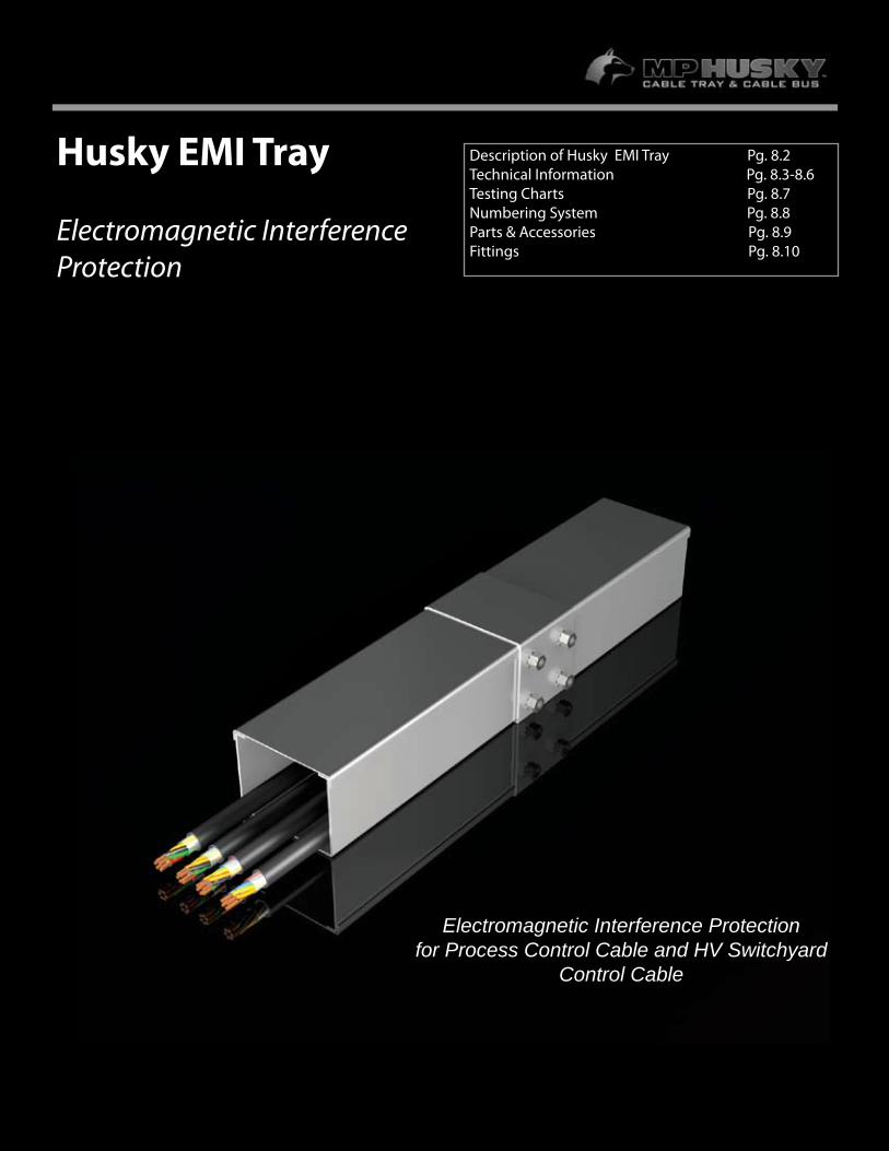
7.1
Husky EMI Tray
Electromagnetic Interference Protection
Description of Husky EMI Tray Pg. 8.2Technical Information Pg. 8.3-8.6Testing Charts Pg. 8.7 Numbering System Pg. 8.8Parts & Accessories Pg. 8.9Fittings Pg. 8.10
Electromagnetic Interference Protectionfor Process Control Cable and HV Switchyard
Control Cable
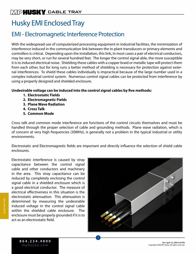
8 6 4 . 2 3 4 . 4 8 0 0m p h u s k y . c o m
Rev. April 16, 2009 4:30 PMCopyright 2008 MP Husky. All rights reserved.
CABLE TRAY
2
Hu
Sky
EMI T
rAy
Husky EMI Enclosed TrayEMI - Electromagnetic Interference ProtectionWith the widespread use of computerized processing equipment in industrial facilities, the minimization of interference induced in the communication link between the in-plant transducers or primary elements and controllers is critical. Depending upon the installation, this link, in most cases a pair of electrical conductors, may be very short, or run for several hundred feet. The longer the control signal able, the more susceptible it is to induced electrical noise. Shielding these cables with a copper braid or metallic tape will protect them from each other, but for long runs a better method of shielding is necessary for protection against exter-nal interferences. To shield these cables individually is impractical because of the large number used in a complex industrial control system. Numerous control signal cables can be protected from interference by using a properly designed and shielded enclosure.
Undesirable voltage can be induced into the control signal cables by five methods: 1. Electrostatic Fields 2. Electromagnetic Fields 3. Plane Wave Radiation 4. Cross Talk 5. Common Mode
Cross talk and common mode interference are functions of the control circuits themselves and must be handled through the proper selection of cable and grounding methods. Plane wave radiation, which is of concern at very high frequencies (30MHz), is generally not a problem in the typical industrial or utility environments.
Electrostatic and Electromagnetic fields are important and directly influence the selection of shield cable enclosures.
Electrostatic interference is caused by stray capacitance between the control signal cable and other conductors and machinery in the area. This stray capacitance can be reduced by completely enclosing the control signal cable in a shielded enclosure which is a good electrical conductor. The measure of electrical effectiveness in this situation is the electrostatic attenuation. This attenuation is determined by measuring the undesirable induced voltage in the control signal cable within the shielded cable enclosure. The enclosure must be properly grounded if it is to act as an electrostatic field.
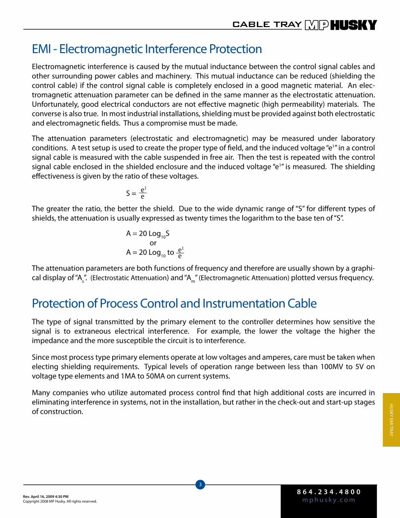
8 6 4 . 2 3 4 . 4 8 0 0m p h u s k y . c o mRev. April 16, 2009 4:30 PM
Copyright 2008 MP Husky. All rights reserved.
CABLE TRAY
3
Hu
Sky EMI TrAy
EMI - Electromagnetic Interference ProtectionElectromagnetic interference is caused by the mutual inductance between the control signal cables and other surrounding power cables and machinery. This mutual inductance can be reduced (shielding the control cable) if the control signal cable is completely enclosed in a good magnetic material. An elec-tromagnetic attenuation parameter can be defined in the same manner as the electrostatic attenuation. unfortunately, good electrical conductors are not effective magnetic (high permeability) materials. The converse is also true. In most industrial installations, shielding must be provided against both electrostatic and electromagnetic fields. Thus a compromise must be made.
The attenuation parameters (electrostatic and electromagnetic) may be measured under laboratory conditions. A test setup is used to create the proper type of field, and the induced voltage “e1” in a control signal cable is measured with the cable suspended in free air. Then the test is repeated with the control signal cable enclosed in the shielded enclosure and the induced voltage “e1” is measured. The shielding effectiveness is given by the ratio of these voltages.
S =
The greater the ratio, the better the shield. Due to the wide dynamic range of “S” for different types of shields, the attenuation is usually expressed as twenty times the logarithm to the base ten of “S”.
A = 20 Log10S or A = 20 Log10 to
The attenuation parameters are both functions of frequency and therefore are usually shown by a graphi-cal display of “As”. (Electrostatic Attenuation) and “Am” (Electromagnetic Attenuation) plotted versus frequency.
Protection of Process Control and Instrumentation CableThe type of signal transmitted by the primary element to the controller determines how sensitive the signal is to extraneous electrical interference. For example, the lower the voltage the higher the impedance and the more susceptible the circuit is to interference.
Since most process type primary elements operate at low voltages and amperes, care must be taken when electing shielding requirements. Typical levels of operation range between less than 100MV to 5V on voltage type elements and 1MA to 50MA on current systems.
Many companies who utilize automated process control find that high additional costs are incurred in eliminating interference in systems, not in the installation, but rather in the check-out and start-up stages of construction.
e1 e
e1 e
__
__
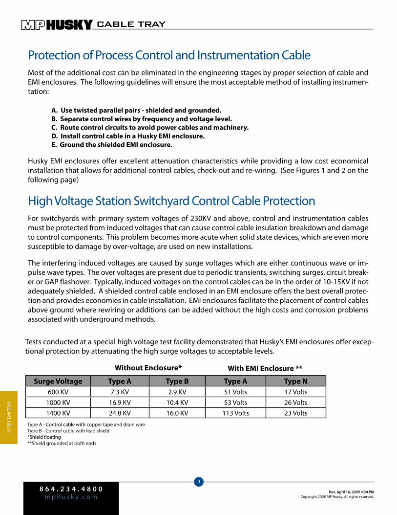
8 6 4 . 2 3 4 . 4 8 0 0m p h u s k y . c o m
Rev. April 16, 2009 4:30 PMCopyright 2008 MP Husky. All rights reserved.
CABLE TRAY
4
Hu
Sky
EMI T
rAy
Protection of Process Control and Instrumentation CableMost of the additional cost can be eliminated in the engineering stages by proper selection of cable and EMI enclosures. The following guidelines will ensure the most acceptable method of installing instrumen-tation:
A. Use twisted parallel pairs - shielded and grounded. B. Separate control wires by frequency and voltage level. C. Route control circuits to avoid power cables and machinery. D. Install control cable in a Husky EMI enclosure. E. Ground the shielded EMI enclosure.
Husky EMI enclosures offer excellent attenuation characteristics while providing a low cost economical installation that allows for additional control cables, check-out and re-wiring. (See Figures 1 and 2 on the following page)
High Voltage Station Switchyard Control Cable ProtectionFor switchyards with primary system voltages of 230kV and above, control and instrumentation cables must be protected from induced voltages that can cause control cable insulation breakdown and damage to control components. This problem becomes more acute when solid state devices, which are even more susceptible to damage by over-voltage, are used on new installations.
The interfering induced voltages are caused by surge voltages which are either continuous wave or im-pulse wave types. The over voltages are present due to periodic transients, switching surges, circuit break-er or GAP flashover. Typically, induced voltages on the control cables can be in the order of 10-15kV if not adequately shielded. A shielded control cable enclosed in an EMI enclosure offers the best overall protec-tion and provides economies in cable installation. EMI enclosures facilitate the placement of control cables above ground where rewiring or additions can be added without the high costs and corrosion problems associated with underground methods.
Tests conducted at a special high voltage test facility demonstrated that Husky’s EMI enclosures offer excep-tional protection by attenuating the high surge voltages to acceptable levels.
Surge Voltage Type A Type B Type A Type N600 kV 7.3 kV 2.9 kV 51 Volts 17 Volts
1000 kV 16.9 kV 10.4 kV 53 Volts 26 Volts1400 kV 24.8 kV 16.0 kV 113 Volts 23 Volts
Without Enclosure* With EMI Enclosure **
Type A - Control cable with copper tape and drain wireType B - Control cable with lead shield*Shield floating**Shield grounded at both ends
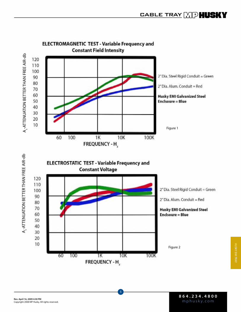
8 6 4 . 2 3 4 . 4 8 0 0m p h u s k y . c o mRev. April 16, 2009 4:30 PM
Copyright 2008 MP Husky. All rights reserved.
CABLE TRAY
5
Hu
Sky EMI TrAy
As-A
TTEN
uAT
ION
BET
TEr
THA
N F
rEE
AIr
-db
As-A
TTEN
uAT
ION
BET
TEr
THA
N F
rEE
AIr
-db
Figure 1
Figure 2
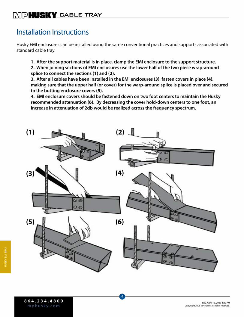
8 6 4 . 2 3 4 . 4 8 0 0m p h u s k y . c o m
Rev. April 16, 2009 4:30 PMCopyright 2008 MP Husky. All rights reserved.
CABLE TRAY
6
Hu
Sky
EMI T
rAy
Installation InstructionsHusky EMI enclosures can be installed using the same conventional practices and supports associated with standard cable tray.
1. After the support material is in place, clamp the EMI enclosure to the support structure. 2. When joining sections of EMI enclosures use the lower half of the two piece wrap-around splice to connect the sections (1) and (2). 3. After all cables have been installed in the EMI enclosures (3), fasten covers in place (4), making sure that the upper half (or cover) for the warp-around splice is placed over and secured to the butting enclosure covers (5). 4. EMI enclosure covers should be fastened down on two foot centers to maintain the Husky recommended attenuation (6). By decreasing the cover hold-down centers to one foot, an increase in attenuation of 2db would be realized across the frequency spectrum.
(1) (2)
(3) (4)
(5) (6)

8 6 4 . 2 3 4 . 4 8 0 0m p h u s k y . c o mRev. April 16, 2009 4:30 PM
Copyright 2008 MP Husky. All rights reserved.
CABLE TRAY
7
Hu
Sky EMI TrAy
Specification for Husky EMI Enclosures1.0 General 1.01 Scope This specification shall include all the necessary materials to provide an EMI enclosure system with a high degree of electrostatic and electromagnetic shielding for low level control circuits. The enclosures shall be designed and constructed to equal or better the EM-shielding attributes herein specified, over the frequency range of 60 Hz to 100 kHz. 1.02 Basic Design To meet the requirements of this specification the cable tray and cover must totally enclose the specified cables, circuits, and/or devices with metal. Non-metallic materials are not acceptable for this purpose.2.0 Attenuation Requirements 2.01 Electrostatic Attenuation The minimum acceptable electrostatic (electric field) shielding efficiency for the enclosure to be supplied for this installation shall be 86 db in the range of 60Hz to 100 kHz. 2.02 Electromagnetic Attenuation The minimum magnetic field shielding efficiency shall increase from 9 db to 55 db over the frequency range of 60 Hz through 100 kHz. 2.03 Certification The enclosure manufacturer shall certify in writing that the EMI enclosure to be provided will, in fact, equal or better the shielding efficiency of Paragraphs 2.01 and 2.02. Such certification will consist of a report of evaluation tests performed by the manufacturer or by an independent testing laboratory. The report will describe the enclosure, the test methods used to evaluate the product and technical data (graphics, charts, etc.) supporting the shielding performance claims for the product.3.0 Additional Requirements 3.01 General In addition to the above attenuation requirements, it is intended that the completed EMI enclosure system be readily accessible for installation, re-arrangement, and inspection of cables supported. Additionally, the enclosure provided shall meet the following electrical and mechanical requirements. 3.02 Electrical Continuity and Grounding All components of the enclosure system shall be thoroughly grounded to conform with the grounding requirements of the N.E.C. A bare copper bonding cable shall be installed in the enclosure to provide adequate grounding continuity. Each section of the enclosure and all fittings shall be securely bonded to the ground bus in the enclosure with suitable grounding fitting to ascertain continuity to ground throughout the enclosure system. 3.03 Material Specifications All members of the enclosure system, unless specifically stated herein, shall be made from ASTM A653-G90 Steel, and all EMI enclosures shall be hot-dip mill galvanized. Application of design rules and fabrication shall be in accordance with ASTM Specifications and A.W.S. Standards. The hot-dip galvanize protective covering shall conform to ASTM Standards. 3.04 Approval of EMI Enclosure The Contractor shall submit for approval, as soon as practical and within thirty days after the award of contract and before the purchase of material, a complete schedule of the materials and equipment proposed for installation, including the specified data. Data to be submitted for approval shall consist of the Manufacturers name and the following items for each type of enclosure to be furnished: Typical Sample, Certified Attenuation Data .

8 6 4 . 2 3 4 . 4 8 0 0m p h u s k y . c o m
Rev. April 16, 2009 4:30 PMCopyright 2008 MP Husky. All rights reserved.
CABLE TRAY
8
Hu
Sky
EMI T
rAy
Numbering / Ordering Information
Other Technical DataMaterial: ASTM-A653 G90 SteelStandard Finish:Hot-dip mill-galvanized. (Other finishes available upon request)Parts Included:Each straight includes cover, wrap-around splice, hardware and self-drilling cover screws.Other:EMI is manufactured and tested in accordance with NEMA VE-1 and is installed in accordance with NEMA VE-2 “Cable Tray In-stallation Guidelines”.
(For other tray sizes or specifications, please consult the factory)
EM(D)-(W)-144
Tray Type:EMI
Enclosure
Depth:4”6”
Width:6”9”12”18”24”
Length:
12’ (144”)
EM D- W- 144
Tray Type Diameter Width Length

8 6 4 . 2 3 4 . 4 8 0 0m p h u s k y . c o mRev. April 16, 2009 4:30 PM
Copyright 2008 MP Husky. All rights reserved.
CABLE TRAY
9
Hu
Sky EMI TrAy
6 8 10 12(D)
Depth(inches)
(W)Width
(inches)Load Deflection Load Deflection Load Deflection Load Deflection
24 222* .17 130 .32 83 .50 58 .7218 230 .18 130 .32 83 .50 58 .72
4 12 230 .18 130 .32 83 .50 58 .729 230 .18 130 .32 83 .50 58 .726 230 .18 130 .32 83 .50 58 .72
24 221* .06 185 .16 118 .25 82 .3618 296* .08 185 .16 118 .25 82 .36
6 12 328 .09 185 .16 118 .25 82 .369 328 .09 185 .16 118 .25 82 .366 328 .09 185 .16 118 .25 82 .36
SPAN FEET
*Indicates allowable load is limited by the load carrying capacity of the transverse member.
Cover Holding DevicesCatalog No. B-26All holding devices should be located on 2 foot centers, or less.Standard - Self drilling sheet metal screws.
Optional Holding DevicesBanding - Available in 302 Stainless Steel, is an economi-cal way of securing the cover to the enclosure.
Item Catalog No.100’ roll 1/2” wide SCCB-100
Clips - 1/2” wide SCCB-C
Strapping Tool CCB-T
ClampsPermit the easy removal of cover and access to cable. reusable.
Length Catalog No.4” JCC
6” MCC
Warp-Around SpliceCatalog No. EMS(D)-(W)Specify size of splice by inserting depth & width in place of “D” and “W”. The splice is supplied with all necessary hardware.
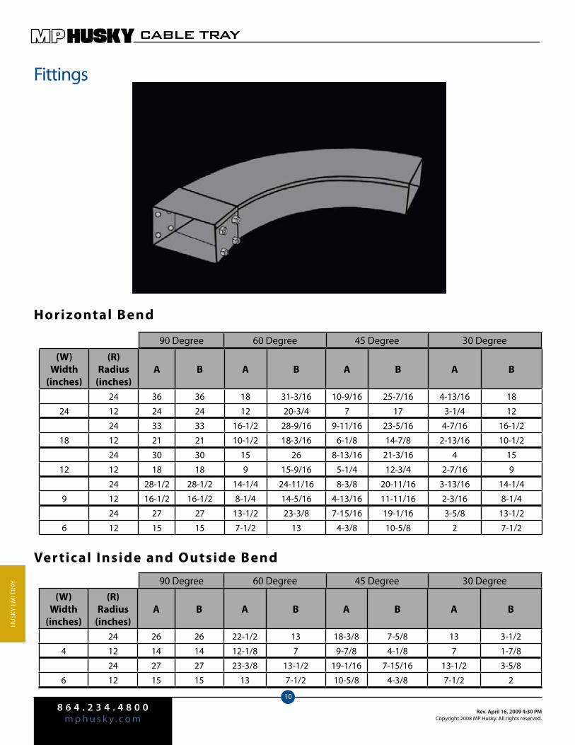
8 6 4 . 2 3 4 . 4 8 0 0m p h u s k y . c o m
Rev. April 16, 2009 4:30 PMCopyright 2008 MP Husky. All rights reserved.
CABLE TRAY
10
Hu
Sky
EMI T
rAy
Fittings
(W)Width
(inches)
(R)Radius
(inches)A B A B A B A B
24 36 36 18 31-3/16 10-9/16 25-7/16 4-13/16 18
24 12 24 24 12 20-3/4 7 17 3-1/4 12
24 33 33 16-1/2 28-9/16 9-11/16 23-5/16 4-7/16 16-1/2
18 12 21 21 10-1/2 18-3/16 6-1/8 14-7/8 2-13/16 10-1/2
24 30 30 15 26 8-13/16 21-3/16 4 15
12 12 18 18 9 15-9/16 5-1/4 12-3/4 2-7/16 9
24 28-1/2 28-1/2 14-1/4 24-11/16 8-3/8 20-11/16 3-13/16 14-1/4
9 12 16-1/2 16-1/2 8-1/4 14-5/16 4-13/16 11-11/16 2-3/16 8-1/4
24 27 27 13-1/2 23-3/8 7-15/16 19-1/16 3-5/8 13-1/2
6 12 15 15 7-1/2 13 4-3/8 10-5/8 2 7-1/2
90 Degree 60 Degree 45 Degree 30 Degree
Horizontal Bend
(W)Width
(inches)
(R)Radius
(inches)A B A B A B A B
24 26 26 22-1/2 13 18-3/8 7-5/8 13 3-1/2
4 12 14 14 12-1/8 7 9-7/8 4-1/8 7 1-7/8
24 27 27 23-3/8 13-1/2 19-1/16 7-15/16 13-1/2 3-5/8
6 12 15 15 13 7-1/2 10-5/8 4-3/8 7-1/2 2
90 Degree 60 Degree 45 Degree 30 Degree
Ver tical Inside and Outside Bend
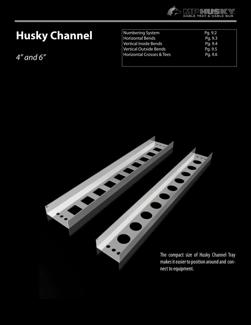
8.1
For more information or to order, call 1-800-277-4810 or visit www.mphusky.com.
Husky Channel
4” and 6”
Numbering System Pg. 9.2Horizontal Bends Pg. 9.3 Vertical Inside Bends Pg. 9.4Vertical Outside Bends Pg. 9.5Horizontal Crosses & Tees Pg. 9.6
The compact size of Husky Channel Tray makes it easier to position around and con-nect to equipment.

8 6 4 . 2 3 4 . 4 8 0 0m p h u s k y . c o m
Rev. April 16, 2009 4:33 PMCopyright 2008 MP Husky. All rights reserved.
CABLE TRAY
2CHA
NN
el
Basic Catalog No.
SSG-6-144
Channel Numbering System
Other Technical DataDepth:1-3/4 inches outside with a loading depth of 1-5/8 inches inside.Fittings:12, 24, or 36 inch standard radii (See this section of this catalog). Channel Bottoms:All channels have flat bottoms and are available with or without ventilation holes. All fittings are non-ventilated.Splice Plates:Straight sections and fittings are supplied with splice plates and hardware.Safety Factor: 1.5 NEMA Standard
StainlessSteel 304
StainlessSteel 316
HDGAF Steel
Mill-GalvSteel Aluminum
4G- 6G- SG- PG- AG-
4SG- 6SG- SSG- PSG- ASG-
Type Prefix
Straight Sections & Fittings
S S G- 6- 144
MaterialSolid
BottomTray Type
Width in Inches
Length in Inches
Materials:A=Aluminum
S=HDGAF SteelP=Mill Galv Steel
4=Stainless Steel 3046=Stainless Steel 316
BottomIndicates solid bottom channelOmit this “S” if
you do not require solid bottom tray
Tray Types:AluminumAG, ASG
SteelSG, SSG, PG, PSG, 4G,
4SG, 6G, 6SG
Widths:4”6”
Lengths:12’ (144”)24’ (288”)
Width(In.)
Approx. Weight
(lbs./ft.)
6
Load Defl
8
Load Defl
10
Load Defl
12
Load Defl
14
Load Defl
Steel 46
1.301.43
- - - - - -- - - - - -
22.5 .5723.5 .54
14.4 .8915.0 .86
10.0 1.2910.4 1.23
7.35 1.757.70 1.68
Aluminum 46
.68
.74- - - - - -- - - - - -
22.4 1.1023.4 1.05
14.3 1.7215.0 1.65
10.0 2.4710.4 2.37
7.30 3.377.60 3.23
Span (Feet)
P R E F I X
Width(in inches) Length
(in inches)
4”, 6” 144”, 288”
4”, 6” 144”, 288”
Bottom
Ventilated
Solid
Table 6.1
Table 6.2
* Use 288 for 24’ length
Loading Tables
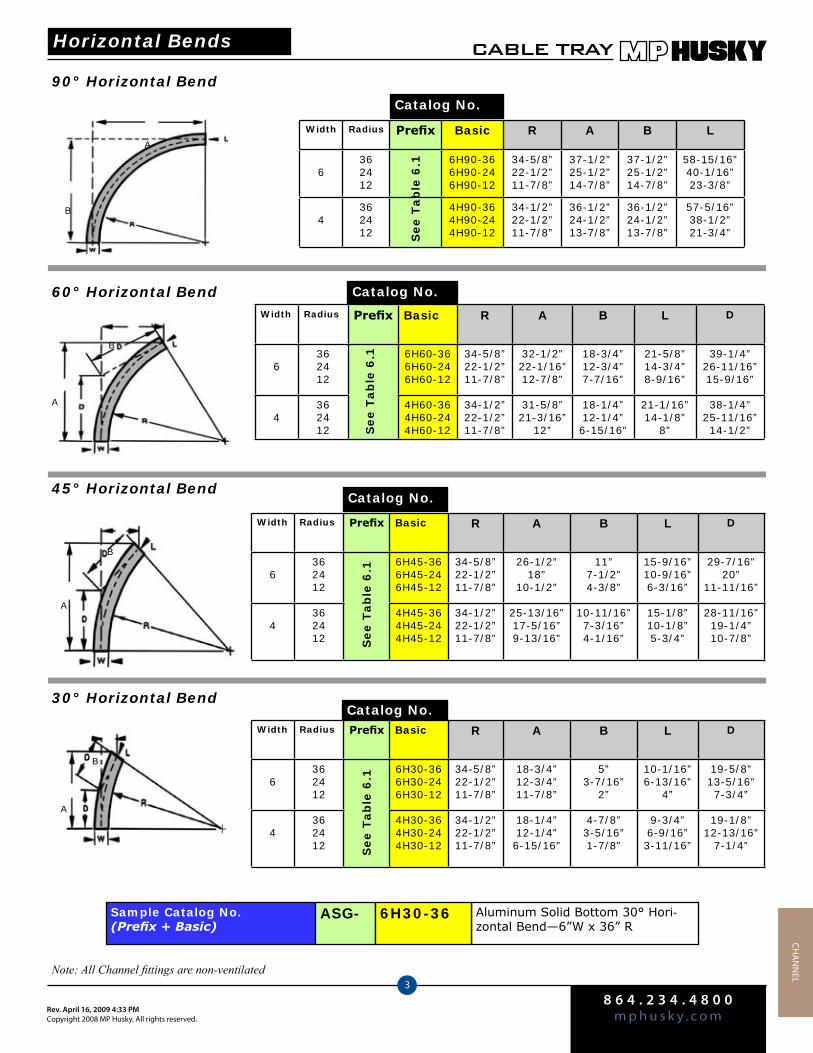
8 6 4 . 2 3 4 . 4 8 0 0m p h u s k y . c o mRev. April 16, 2009 4:33 PM
Copyright 2008 MP Husky. All rights reserved.
CABLE TRAY
3
CHA
NN
el
Width Radius Prefix Basic R A B L
6362412
6H90-366H90-246H90-12
34-5/8”22-1/2”11-7/8”
37-1/2”25-1/2”14-7/8”
37-1/2”25-1/2”14-7/8”
58-15/16”40-1/16”23-3/8”
4362412
4H90-364H90-244H90-12
34-1/2”22-1/2”11-7/8”
36-1/2”24-1/2”13-7/8”
36-1/2”24-1/2”13-7/8”
57-5/16”38-1/2”21-3/4”
90° Horizontal Bend
Catalog No.
Width Radius Prefix Basic R A B L D
6362412
6H60-366H60-246H60-12
34-5/8”22-1/2”11-7/8”
32-1/2”22-1/16”12-7/8”
18-3/4”12-3/4”7-7/16”
21-5/8”14-3/4”8-9/16”
39-1/4”26-11/16”15-9/16”
4362412
4H60-364H60-244H60-12
34-1/2”22-1/2”11-7/8”
31-5/8”21-3/16”
12”
18-1/4”12-1/4”6-15/16”
21-1/16”14-1/8”
8”
38-1/4”25-11/16”14-1/2”
60° Horizontal Bend Catalog No.
45° Horizontal BendCatalog No.
30° Horizontal BendCatalog No.
Sample Catalog No.(Prefix + Basic)
Aluminum Solid Bottom 30° Hori-zontal Bend—6”W x 36” R
ASG- 6H30-36
See T
ab
le 6
.1S
ee T
ab
le 6
.1
See T
ab
le 6
.1
A
B
A
B
B
A
A
B
Note: All Channel fittings are non-ventilated
Width Radius Prefix Basic R A B L D
6362412
6H45-366H45-246H45-12
34-5/8”22-1/2”11-7/8”
26-1/2”18”
10-1/2”
11”7-1/2”4-3/8”
15-9/16”10-9/16”6-3/16”
29-7/16”20”
11-11/16”
4362412
4H45-364H45-244H45-12
34-1/2”22-1/2”11-7/8”
25-13/16”17-5/16”9-13/16”
10-11/16”7-3/16”4-1/16”
15-1/8”10-1/8”5-3/4”
28-11/16”19-1/4”10-7/8”S
ee T
ab
le 6
.1
Width Radius Prefix Basic R A B L D
6362412
6H30-366H30-246H30-12
34-5/8”22-1/2”11-7/8”
18-3/4”12-3/4”11-7/8”
5”3-7/16”
2”
10-1/16”6-13/16”
4”
19-5/8”13-5/16”7-3/4”
4362412
4H30-364H30-244H30-12
34-1/2”22-1/2”11-7/8”
18-1/4”12-1/4”6-15/16”
4-7/8”3-5/16”1-7/8”
9-3/4”6-9/16”3-11/16”
19-1/8”12-13/16”
7-1/4”See T
ab
le 6
.1
Horizontal Bends
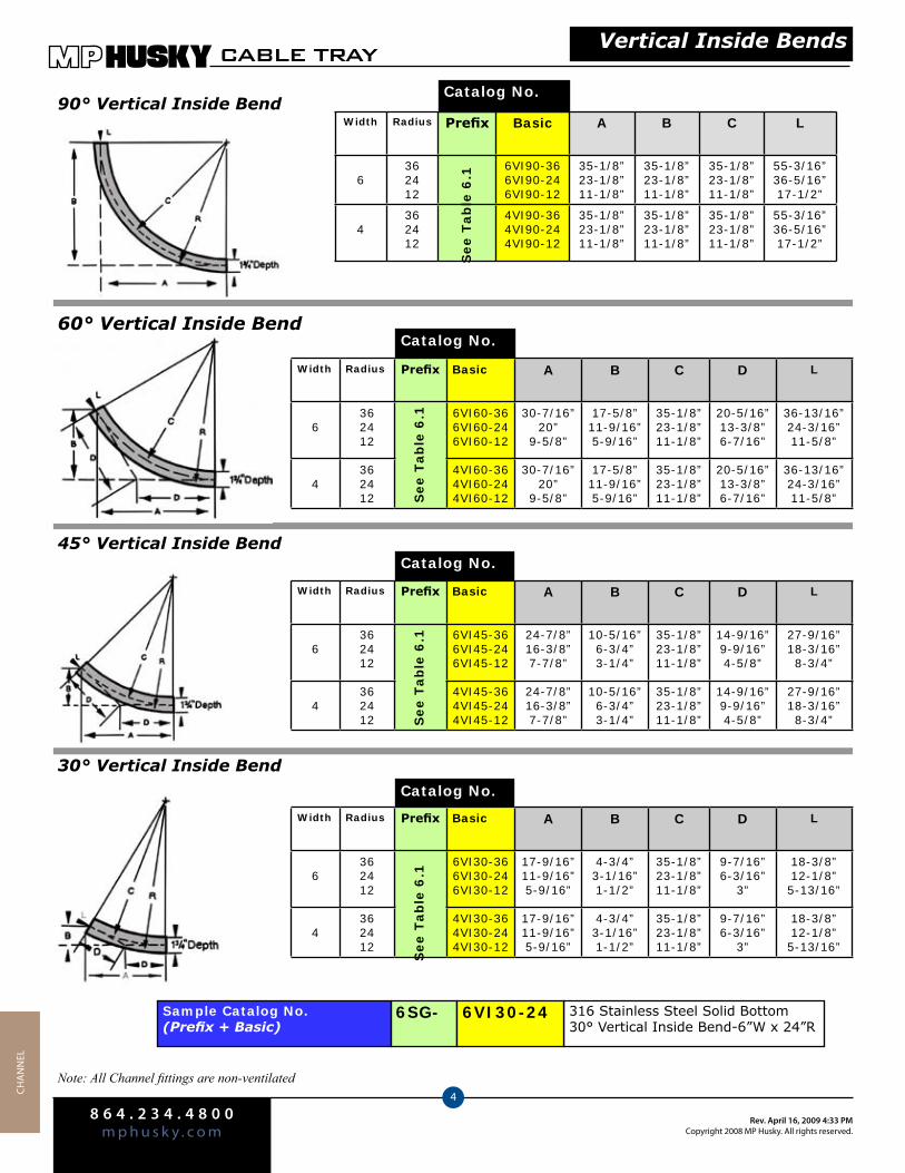
8 6 4 . 2 3 4 . 4 8 0 0m p h u s k y . c o m
Rev. April 16, 2009 4:33 PMCopyright 2008 MP Husky. All rights reserved.
CABLE TRAY
4CHA
NN
el
Width Radius Prefix Basic A B C L
6362412
6VI90-366VI90-246VI90-12
35-1/8”23-1/8”11-1/8”
35-1/8”23-1/8”11-1/8”
35-1/8”23-1/8”11-1/8”
55-3/16”36-5/16”17-1/2”
4362412
4VI90-364VI90-244VI90-12
35-1/8”23-1/8”11-1/8”
35-1/8”23-1/8”11-1/8”
35-1/8”23-1/8”11-1/8”
55-3/16”36-5/16”17-1/2”
90° Vertical Inside BendCatalog No.
60° Vertical Inside BendCatalog No.
45° Vertical Inside BendCatalog No.
30° Vertical Inside Bend
Catalog No.
See T
ab
le 6
.1
Sample Catalog No.(Prefix + Basic)
316 Stainless Steel Solid Bottom 30° Vertical Inside Bend-6”W x 24”R
6SG- 6VI30-24
Note: All Channel fittings are non-ventilated
Vertical Inside Bends
Width Radius Prefix Basic A B C D L
6362412
6VI60-366VI60-246VI60-12
30-7/16”20”
9-5/8”
17-5/8”11-9/16”5-9/16”
35-1/8”23-1/8”11-1/8”
20-5/16”13-3/8”6-7/16”
36-13/16”24-3/16”11-5/8”
4362412
4VI60-364VI60-244VI60-12
30-7/16”20”
9-5/8”
17-5/8”11-9/16”5-9/16”
35-1/8”23-1/8”11-1/8”
20-5/16”13-3/8”6-7/16”
36-13/16”24-3/16”11-5/8”S
ee T
ab
le 6
.1
Width Radius Prefix Basic A B C D L
6362412
6VI45-366VI45-246VI45-12
24-7/8”16-3/8”7-7/8”
10-5/16”6-3/4”3-1/4”
35-1/8”23-1/8”11-1/8”
14-9/16”9-9/16”4-5/8”
27-9/16”18-3/16”8-3/4”
4362412
4VI45-364VI45-244VI45-12
24-7/8”16-3/8”7-7/8”
10-5/16”6-3/4”3-1/4”
35-1/8”23-1/8”11-1/8”
14-9/16”9-9/16”4-5/8”
27-9/16”18-3/16”8-3/4”S
ee T
ab
le 6
.1
Width Radius Prefix Basic A B C D L
6362412
6VI30-366VI30-246VI30-12
17-9/16”11-9/16”5-9/16”
4-3/4”3-1/16”1-1/2”
35-1/8”23-1/8”11-1/8”
9-7/16”6-3/16”
3”
18-3/8”12-1/8”5-13/16”
4362412
4VI30-364VI30-244VI30-12
17-9/16”11-9/16”5-9/16”
4-3/4”3-1/16”1-1/2”
35-1/8”23-1/8”11-1/8”
9-7/16”6-3/16”
3”
18-3/8”12-1/8”5-13/16”
See T
ab
le 6
.1

8 6 4 . 2 3 4 . 4 8 0 0m p h u s k y . c o mRev. April 16, 2009 4:33 PM
Copyright 2008 MP Husky. All rights reserved.
CABLE TRAY
5
CHA
NN
el
90° Vertical Outside BendCatalog No.
60° Vertical Outside BendCatalog No.
45° Vertical Outside Bend
30° Vertical Outside Bend
Sample Catalog No.(Prefix + Basic)
HDGAF Steel Solid Bottom 45° Vertical Outside Bend—6”W x 12” R
SSG- 6VO45-12
Note: All Channel fittings are non-ventilated
Width Radius Prefix Basic A B C L
6362412
6VO90-366VO90-246VO90-12
36-7/8”24-7/8”12-7/8”
36-7/8”24-7/8”12-7/8”
36-7/8”24-7/8”12-7/8”
57-15/16”39-1/16”20-1/4”
4362412
4VO90-364VO90-244VO90-12
36-7/8”24-7/8”12-7/8”
36-7/8”24-7/8”12-7/8”
36-7/8”24-7/8”12-7/8”
57-15/16”39-1/16”20-1/4”
See T
ab
le 6
.1
Vertical Outside Bends
Width Radius Prefix Basic A B C D L
6362412
6VO60-366VO60-246VO60-12
31-15/16”21-9/16”11-1/8”
18-7/16”12-7/16”6-7/16”
36-7/8”24-7/8”12-7/8”
21-5/16”14-3/8”7-7/16”
38-5/8”26-1/16”13-7/16”
4362412
4VO60-364VO60-244VO60-12
31-15/16”21-9/16”11-1/8”
18-7/16”12-7/16”6-7/16”
36-7/8”24-7/8”12-7/8”
21-5/16”14-3/8”7-7/16”
38-5/8”26-1/16”13-7/16”S
ee T
ab
le 6
.1
Catalog No.
Width Radius Prefix Basic A B C D L
6362412
6VO45-366VO45-246VO45-12
26-1/16”17-9/16”9-1/8”
10-3/4”7-5/16”3-3/4”
36-7/8”24-7/8”12-7/8”
15-1/4”10-5/16”5-5/16”
28-15/16”19-9/16”10-1/8”
4362412
4VO45-364VO45-244VO45-12
26-1/16”17-9/16”9-1/8”
10-3/4”7-5/16”3-3/4”
36-7/8”24-7/8”12-7/8”
15-1/4”10-5/16”5-5/16”
28-15/16”19-9/16”10-1/8”S
ee T
ab
le 6
.1
Catalog No.
Width Radius Prefix Basic A B C D L
6362412
6VO30-366VO30-246VO30-12
18-7/16”12-7/16”5-7/16”
4-15/16”3-5/16”1-3/4”
36-7/8”24-7/8”12-7/8”
9-7/8”6-5/8”3-7/16”
19-5/16”13”
6-3/4”
4362412
4VO30-364VO30-244VO30-12
18-7/16”12-7/16”5-7/16”
4-15/16”3-5/16”1-3/4”
36-7/8”24-7/8”12-7/8”
9-7/8”6-5/8”3-7/16”
19-5/16”13”
6-3/4”See T
ab
le 6
.1
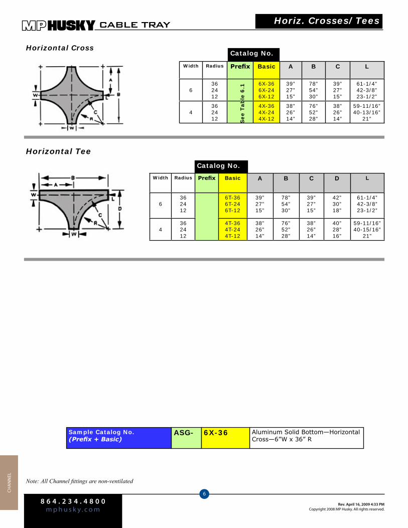
8 6 4 . 2 3 4 . 4 8 0 0m p h u s k y . c o m
Rev. April 16, 2009 4:33 PMCopyright 2008 MP Husky. All rights reserved.
CABLE TRAY
6CHA
NN
el
Width Radius Prefix Basic A B C L
6362412
6X-366X-246X-12
39”27”15”
78”54”30”
39”27”15”
61-1/4”42-3/8”23-1/2”
4362412
4X-364X-244X-12
38”26”14”
76”52”28”
38”26”14”
59-11/16”40-13/16”
21”
Horizontal CrossCatalog No.
Horizontal Tee
Catalog No.
See T
ab
le 6
.1
See T
ab
le 6
.1
Sample Catalog No.(Prefix + Basic)
Aluminum Solid Bottom—Horizontal Cross—6”W x 36” R
ASG- 6X-36
Note: All Channel fittings are non-ventilated
Horiz. Crosses/Tees
Width Radius Prefix Basic A B C D L
6362412
6T-366T-246T-12
39”27”15”
78”54”30”
39”27”15”
42”30”18”
61-1/4”42-3/8”23-1/2”
4362412
4T-364T-244T-12
38”26”14”
76”52”28”
38”26”14”
40”28”16”
59-11/16”40-15/16”
21”
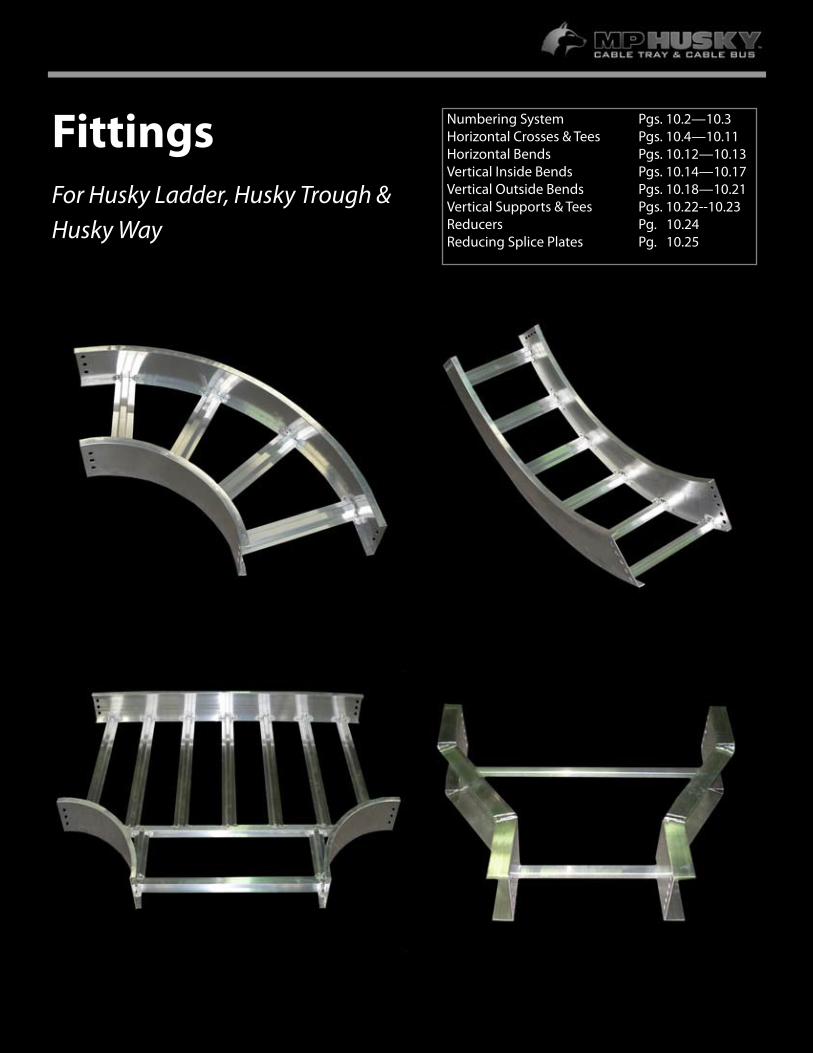
9.1
FittingsFor Husky Ladder, Husky Trough & Husky Way
Numbering System Pgs. 10.2—10.3Horizontal Crosses & Tees Pgs. 10.4—10.11Horizontal Bends Pgs. 10.12—10.13 Vertical Inside Bends Pgs. 10.14—10.17Vertical Outside Bends Pgs. 10.18—10.21Vertical Supports & Tees Pgs. 10.22--10.23Reducers Pg. 10.24Reducing Splice Plates Pg. 10.25
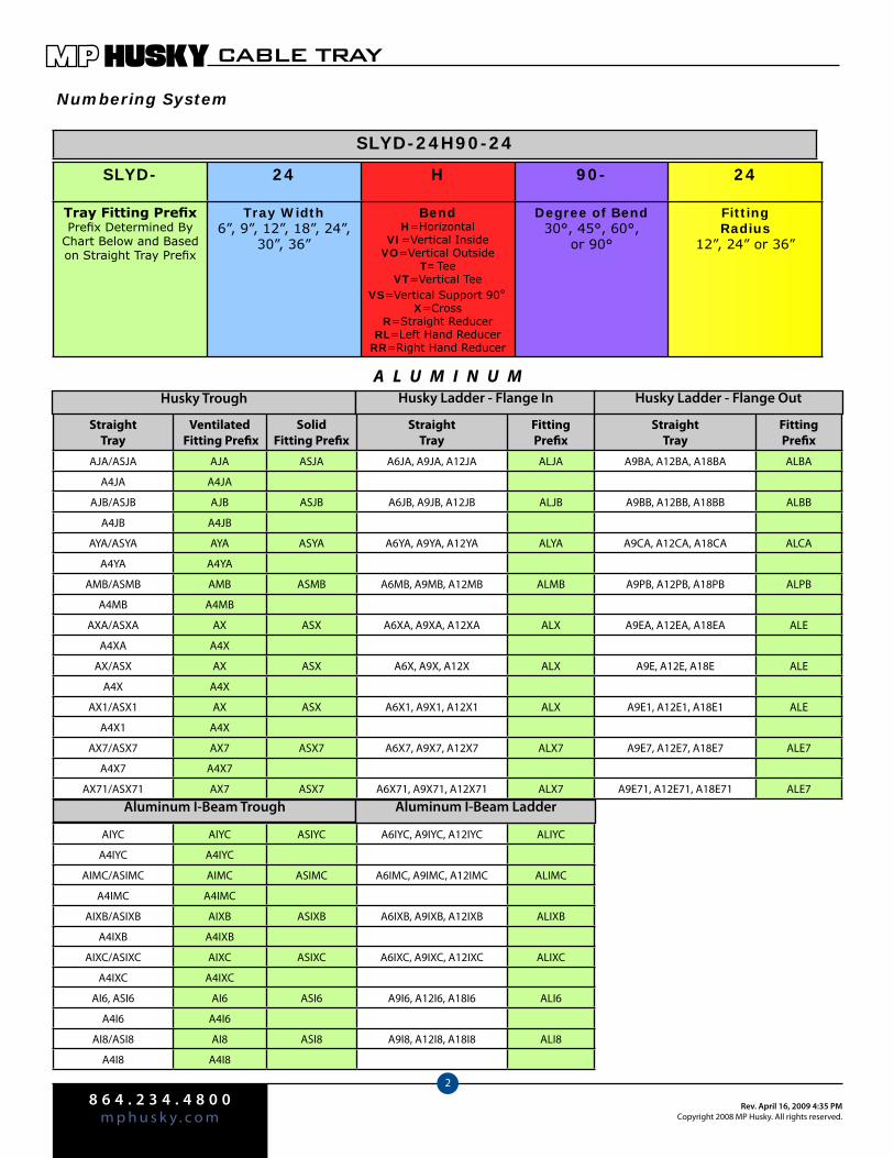
8 6 4 . 2 3 4 . 4 8 0 0m p h u s k y . c o m
Rev. April 16, 2009 4:35 PMCopyright 2008 MP Husky. All rights reserved.
CABLE TRAY
2
Numbering System
SLYD- 24 H 90- 24
Tray Fitting PrefixPrefix Determined By
Chart Below and Based on Straight Tray Prefix
Tray Width6”, 9”, 12”, 18”, 24”,
30”, 36”
BendH=Horizontal
VI=Vertical InsideVO=Vertical Outside
T=TeeVT=Vertical Tee
VS=Vertical Support 90°X=Cross
R=Straight ReducerRL=Left Hand Reducer
RR=Right Hand Reducer
Degree of Bend30°, 45°, 60°,
or 90°
Fitting Radius
12”, 24” or 36”
SLYD-24H90-24
Straight Tray
Ventilated Fitting Prefix
Solid Fitting Prefix
StraightTray
Fitting Prefix
StraightTray
Fitting Prefix
AJA/ASJA AJA ASJA A6JA, A9JA, A12JA ALJA A9BA, A12BA, A18BA ALBA
A4JA A4JA
AJB/ASJB AJB ASJB A6JB, A9JB, A12JB ALJB A9BB, A12BB, A18BB ALBB
A4JB A4JB
AYA/ASYA AYA ASYA A6YA, A9YA, A12YA ALYA A9CA, A12CA, A18CA ALCA
A4YA A4YA
AMB/ASMB AMB ASMB A6MB, A9MB, A12MB ALMB A9PB, A12PB, A18PB ALPB
A4MB A4MB
AXA/ASXA AX ASX A6XA, A9XA, A12XA ALX A9EA, A12EA, A18EA ALE
A4XA A4X
AX/ASX AX ASX A6X, A9X, A12X ALX A9E, A12E, A18E ALE
A4X A4X
AX1/ASX1 AX ASX A6X1, A9X1, A12X1 ALX A9E1, A12E1, A18E1 ALE
A4X1 A4X
AX7/ASX7 AX7 ASX7 A6X7, A9X7, A12X7 ALX7 A9E7, A12E7, A18E7 ALE7
A4X7 A4X7
AX71/ASX71 AX7 ASX7 A6X71, A9X71, A12X71 ALX7 A9E71, A12E71, A18E71 ALE7
Husky Trough Husky Ladder - Flange In Husky Ladder - Flange OutA L U M I N U M
AIYC AIYC ASIYC A6IYC, A9IYC, A12IYC ALIYC
A4IYC A4IYC
AIMC/ASIMC AIMC ASIMC A6IMC, A9IMC, A12IMC ALIMC
A4IMC A4IMC
AIXB/ASIXB AIXB ASIXB A6IXB, A9IXB, A12IXB ALIXB
A4IXB A4IXB
AIXC/ASIXC AIXC ASIXC A6IXC, A9IXC, A12IXC ALIXC
A4IXC A4IXC
AI6, ASI6 AI6 ASI6 A9I6, A12I6, A18I6 ALI6
A4I6 A4I6
AI8/ASI8 AI8 ASI8 A9I8, A12I8, A18I8 ALI8
A4I8 A4I8
Aluminum I-Beam Trough Aluminum I-Beam Ladder
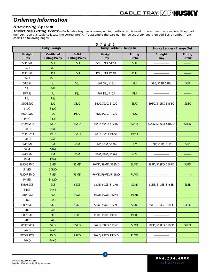
8 6 4 . 2 3 4 . 4 8 0 0m p h u s k y . c o mRev. April 16, 2009 4:35 PM
Copyright 2008 MP Husky. All rights reserved.
CABLE TRAY
3
Numbering SystemInsert the Fitting Prefix—Each cable tray has a corresponding prefix which is used to determine the complete fitting part number. Use this table to locate the correct prefix. To assemble the part number select prefix and then add Basic number from charts on following pages.
Straight Tray
Ventilated Fitting Prefix
Solid Fitting Prefix
StraightTray
Fitting Prefix
StraightTray
Fitting Prefix
SH/SSH SH SSH S6H, S9H, S12H SLH ————— ——-
S4H S4H
PH/PSH PH PSH P6H, P9H, P12H PLH ————— ——-
P4H P4H
SJ/SSJ SJ SSJ S6J, S9J, S12J SLJ S9B, S12B, S18B SLB
S4J S4J
PJ/PSJ PJ PSJ P6J, P9J, P12J PLJ ————— ——-
P4J P4J
SJC/SSJC SJC SSJC S6JC, S9JC, S12JC SLJC S9BC, S12BC, S18BC SLBC
S4JC S4JC
PJC/PSJC PJC PSJC P6JC, P9JC, P12JC PLJC ————— ——-
P4JC P4JC
SYD/SSYD SYD SSYD S6YD, S9YD, S12YD SLYD S9CD, S12CD, S18CD SLCD
S4YD S4YD
PYD/PSYD PYD PSYD P6YD, P9YD, P12YD PLYD —————
P4YD P4YD
SM/SSM SM SSM S6M, S9M, S12M SLM S9P, S12P, S18P SLP
S4M S4M
PM/PSM PM PSM P6M, P9M, P12M PLM ————— ——-
P4M P4M
SMD/SSMD SMD SSMD S6MD, S9MD, S12MD SLMD S9PD, S12PD, S18PD SLPD
S4MD S4MD
PMD/PSMD PMD PSMD P6MD, P9MD, P12MD PLMD ————— ——-
P4MD P4MD
SXB/SSXB SXB SSXB S6XB, S9XB, S12XB SLXB S9EB, S12EB, S18EB SLEB
S4XB S4XB
PXB/PSXB PXB PSXB P6XB, P9XB, P12XB PLXB —————
P4XB P4XB
SXC/SSXC SXC SSXC S6XC, S9XC, S12XC SLXC S9EC, S12EC, S18EC SLEC
S4XC S4XC
PXC/PSXC PXC PSXC P6XC, P9XC, P12XC PLXC —————
P4XC P4XC
SXD/SSXD SXD SSXD S6XD, S9XD, S12XD SLXD S9ED, S12ED, S18ED SLED
S4XD S4XD
PXD/PSXD PXD PSXD P6XD, P9XD, P12XD PLXD —————
P4XD P4XD
S T E E L
Ordering Information
Husky Trough Husky Ladder - Flange In Husky Ladder - Flange Out
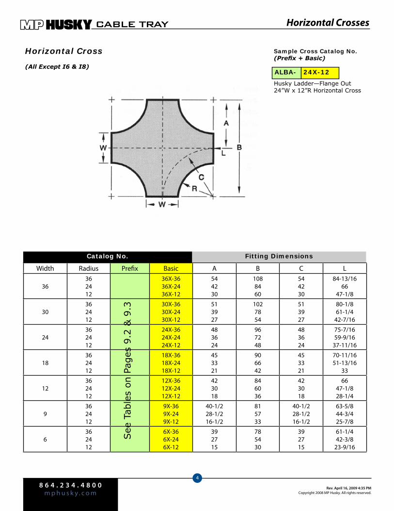
8 6 4 . 2 3 4 . 4 8 0 0m p h u s k y . c o m
Rev. April 16, 2009 4:35 PMCopyright 2008 MP Husky. All rights reserved.
CABLE TRAY
4
Width Radius Prefix Basic A B C L
36362412
36X-3636X-2436X-12
544230
1088460
544230
84-13/1666
47-1/8
30362412
30X-3630X-2430X-12
513927
1027854
513927
80-1/861-1/4
42-7/16
24362412
24X-3624X-2424X-12
483624
967248
483624
75-7/1659-9/16
37-11/16
18362412
18X-3618X-2418X-12
453321
906642
453321
70-11/1651-13/16
33
12362412
12X-3612X-2412X-12
423018
846036
423018
6647-1/828-1/4
9362412
9X-369X-249X-12
40-1/228-1/216-1/2
815733
40-1/228-1/216-1/2
63-5/844-3/425-7/8
6362412
6X-366X-246X-12
392715
785430
392715
61-1/442-3/8
23-9/16
Horizontal Crosses
Horizontal Cross
See
Tab
les
on P
ages
9.2
& 9
.3
Fitting Dimensions
Husky Ladder—Flange Out 24”W x 12”R Horizontal Cross
(All Except I6 & I8)
Sample Cross Catalog No.(Prefix + Basic)
ALBA- 24X-12
Catalog No.
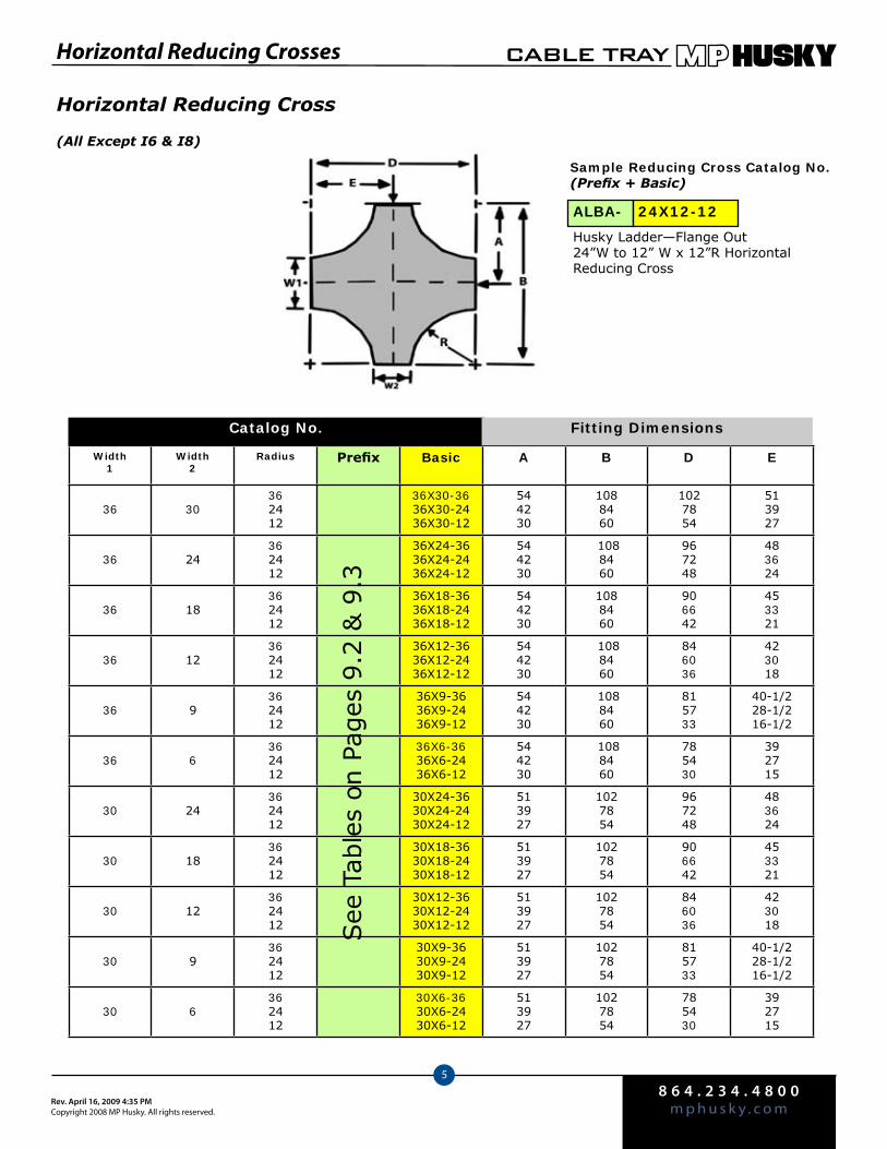
8 6 4 . 2 3 4 . 4 8 0 0m p h u s k y . c o mRev. April 16, 2009 4:35 PM
Copyright 2008 MP Husky. All rights reserved.
CABLE TRAY
5
Horizontal Reducing Crosses
Horizontal Reducing Cross
(All Except I6 & I8)
Husky Ladder—Flange Out24”W to 12” W x 12”R Horizontal Reducing Cross
Sample Reducing Cross Catalog No.(Prefix + Basic)
ALBA- 24X12-12
Width1
Width 2
Radius Prefix Basic A B D E
36 30362412
36X30-3636X30-2436X30-12
544230
1088460
1027854
513927
36 24362412
36X24-3636X24-2436X24-12
544230
1088460
967248
483624
36 18362412
36X18-3636X18-2436X18-12
544230
1088460
906642
453321
36 12362412
36X12-3636X12-2436X12-12
544230
1088460
846036
423018
36 9362412
36X9-3636X9-2436X9-12
544230
1088460
815733
40-1/228-1/216-1/2
36 6362412
36X6-3636X6-2436X6-12
544230
1088460
785430
392715
30 24362412
30X24-3630X24-2430X24-12
513927
1027854
967248
483624
30 18362412
30X18-3630X18-2430X18-12
513927
1027854
906642
453321
30 12362412
30X12-3630X12-2430X12-12
513927
1027854
846036
423018
30 9362412
30X9-3630X9-2430X9-12
513927
1027854
815733
40-1/228-1/216-1/2
30 6362412
30X6-3630X6-2430X6-12
513927
1027854
785430
392715
Catalog No.
See
Tab
les
on P
ages
9.2
& 9
.3
Fitting Dimensions
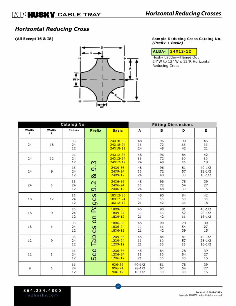
8 6 4 . 2 3 4 . 4 8 0 0m p h u s k y . c o m
Rev. April 16, 2009 4:35 PMCopyright 2008 MP Husky. All rights reserved.
CABLE TRAY
6
Width1
Width 2
Radius Prefix Basic A B D E
24 18362412
24X18-3624X18-2424X18-12
483624
967248
906642
453321
24 12362412
24X12-3624X12-2424X12-12
483624
967248
846036
423018
24 9362412
24X9-3624X9-2424X9-12
483624
967248
815733
40-1/228-1/216-1/2
24 6362412
24X6-3624X6-2424X6-12
483624
967248
785430
392715
18 12362412
18X12-3618X12-2418X12-12
453321
906642
846036
423018
18 9362412
18X9-3618X9-2418X9-12
453321
906642
815733
40-1/228-1/216-1/2
18 6362412
18X6-3618X6-2418X6-12
453321
906642
785439
392715
12 9362412
12X9-3612X9-2412X9-12
453321
846036
815733
40-1/228-1/216-1/2
12 6362412
12X6-3612X6-2412X6-12
453321
846036
785430
392715
9 6362412
9X6-369X6-249X6-12
40-1/228-1/216-1/2
815733
785430
392715
Catalog No.
Horizontal Reducing Cross
(All Except I6 & I8)
Husky Ladder—Flange Out24”W to 12” W x 12”R Horizontal Reducing Cross
Sample Reducing Cross Catalog No.(Prefix + Basic)
ALBA- 24X12-12
See
Tab
les
on P
ages
9.2
& 9
.3
Fitting Dimensions
Horizontal Reducing Crosses
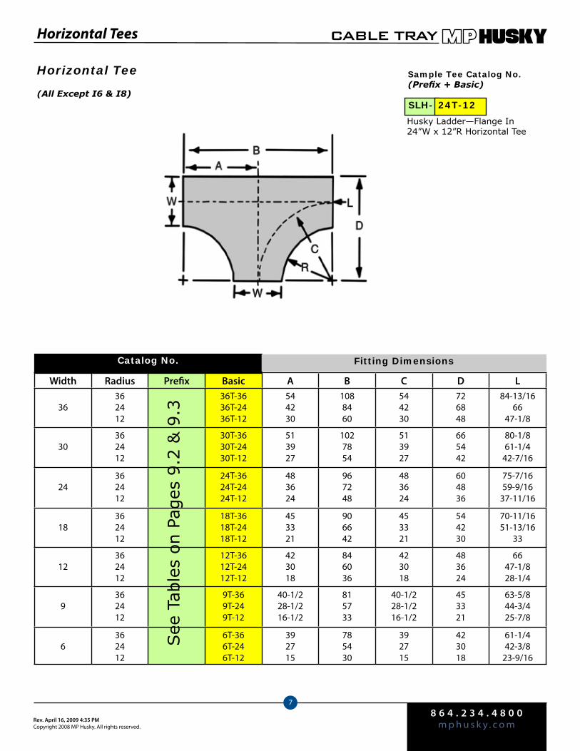
8 6 4 . 2 3 4 . 4 8 0 0m p h u s k y . c o mRev. April 16, 2009 4:35 PM
Copyright 2008 MP Husky. All rights reserved.
CABLE TRAY
7
Width Radius Prefix Basic A B C D L
36362412
36T-3636T-2436T-12
544230
1088460
544230
726848
84-13/1666
47-1/8
30362412
30T-3630T-2430T-12
513927
1027854
513927
665442
80-1/861-1/4
42-7/16
24362412
24T-3624T-2424T-12
483624
967248
483624
604836
75-7/1659-9/16
37-11/16
18362412
18T-3618T-2418T-12
453321
906642
453321
544230
70-11/1651-13/16
33
12362412
12T-3612T-2412T-12
423018
846036
423018
483624
6647-1/828-1/4
9362412
9T-369T-249T-12
40-1/228-1/216-1/2
815733
40-1/228-1/216-1/2
453321
63-5/844-3/425-7/8
6362412
6T-366T-246T-12
392715
785430
392715
423018
61-1/442-3/8
23-9/16
Horizontal Tees
Catalog No.
Horizontal Tee
See
Tab
les
on P
ages
9.2
& 9
.3
Fitting Dimensions
Husky Ladder—Flange In24”W x 12”R Horizontal Tee
Sample Tee Catalog No.(Prefix + Basic)
(All Except I6 & I8)SLH- 24T-12
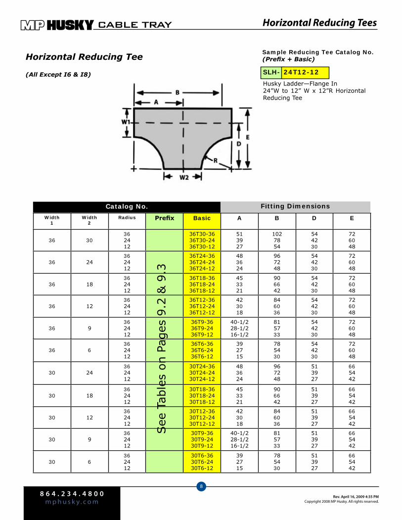
8 6 4 . 2 3 4 . 4 8 0 0m p h u s k y . c o m
Rev. April 16, 2009 4:35 PMCopyright 2008 MP Husky. All rights reserved.
CABLE TRAY
8
Horizontal Reducing Tees
Width1
Width2
Radius Prefix Basic A B D E
36 30362412
36T30-3636T30-2436T30-12
513927
1027854
544230
726048
36 24362412
36T24-3636T24-2436T24-12
483624
967248
544230
726048
36 18362412
36T18-3636T18-2436T18-12
453321
906642
544230
726048
36 12362412
36T12-3636T12-2436T12-12
423018
846036
544230
726048
36 9362412
36T9-3636T9-2436T9-12
40-1/228-1/216-1/2
815733
544230
726048
36 6362412
36T6-3636T6-2436T6-12
392715
785430
544230
726048
30 24362412
30T24-3630T24-2430T24-12
483624
967248
513927
665442
30 18362412
30T18-3630T18-2430T18-12
453321
906642
513927
665442
30 12362412
30T12-3630T12-2430T12-12
423018
846036
513927
665442
30 9362412
30T9-3630T9-2430T9-12
40-1/228-1/216-1/2
815733
513927
665442
30 6362412
30T6-3630T6-2430T6-12
392715
785430
513927
665442
Catalog No.
Horizontal Reducing Tee
See
Tab
les
on P
ages
9.2
& 9
.3
Fitting Dimensions
Husky Ladder—Flange In24”W to 12” W x 12”R Horizontal Reducing Tee
Sample Reducing Tee Catalog No.(Prefix + Basic)
(All Except I6 & I8) SLH- 24T12-12
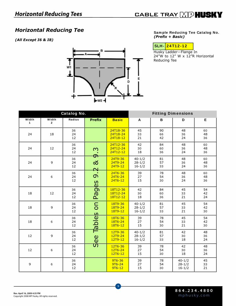
8 6 4 . 2 3 4 . 4 8 0 0m p h u s k y . c o mRev. April 16, 2009 4:35 PM
Copyright 2008 MP Husky. All rights reserved.
CABLE TRAY
9
Horizontal Reducing Tees
Width1
Width2
Radius Prefix Basic A B D E
24 18362412
24T18-3624T18-2424T18-12
453321
906642
483624
604836
24 12362412
24T12-3624T12-2424T12-12
423018
846036
483624
604836
24 9362412
24T9-3624T9-2424T9-12
40-1/228-1/216-1/2
815733
483624
604836
24 6362412
24T6-3624T6-2424T6-12
392715
785430
483624
604836
18 12362412
18T12-3618T12-2418T12-12
423018
846036
453321
544224
18 9362412
18T9-3618T9-2418T9-12
40-1/228-1/216-1/2
815733
453321
544230
18 6362412
18T6-3618T6-2418T6-12
392715
785430
453321
544230
12 9362412
12T9-3612T9-2412T9-12
40-1/228-1/216-1/2
815733
423018
483624
12 6362412
12T6-3612T6-2412T6-12
392715
785430
423018
483624
9 6362412
9T6-369T6-249T6-12
392715
785430
40-1/228-1/216-1/2
453321
Catalog No.
Horizontal Reducing Tee
See
Tab
les
on P
ages
9.2
& 9
.3
Fitting Dimensions
Husky Ladder—Flange In24”W to 12” W x 12”R Horizontal Reducing Tee
Sample Reducing Tee Catalog No.(Prefix + Basic)
(All Except I6 & I8)
SLH- 24T12-12
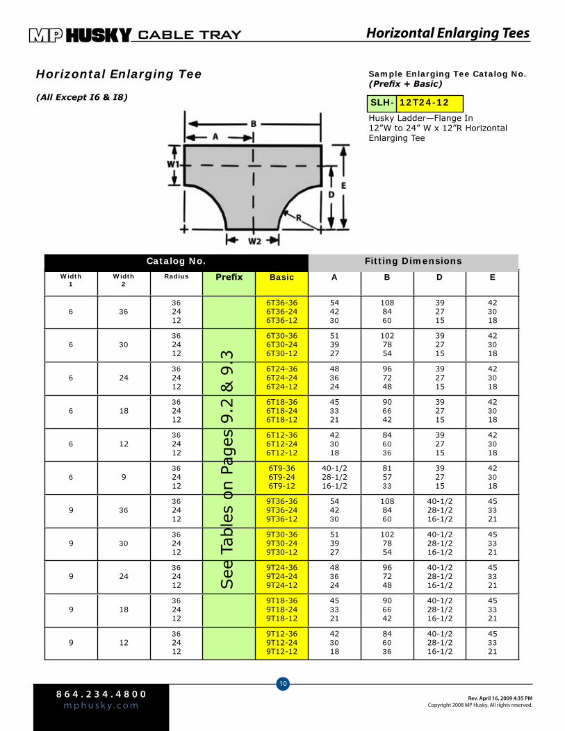
8 6 4 . 2 3 4 . 4 8 0 0m p h u s k y . c o m
Rev. April 16, 2009 4:35 PMCopyright 2008 MP Husky. All rights reserved.
CABLE TRAY
10
Horizontal Enlarging Tees
Width1
Width2
Radius Prefix Basic A B D E
6 36362412
6T36-366T36-246T36-12
544230
1088460
392715
423018
6 30362412
6T30-366T30-246T30-12
513927
1027854
392715
423018
6 24362412
6T24-366T24-246T24-12
483624
967248
392715
423018
6 18362412
6T18-366T18-246T18-12
453321
906642
392715
423018
6 12362412
6T12-366T12-246T12-12
423018
846036
392715
423018
6 9362412
6T9-366T9-246T9-12
40-1/228-1/216-1/2
815733
392715
423018
9 36362412
9T36-369T36-249T36-12
544230
1088460
40-1/228-1/216-1/2
453321
9 30362412
9T30-369T30-249T30-12
513927
1027854
40-1/228-1/216-1/2
453321
9 24362412
9T24-369T24-249T24-12
483624
967248
40-1/228-1/216-1/2
453321
9 18362412
9T18-369T18-249T18-12
453321
906642
40-1/228-1/216-1/2
453321
9 12362412
9T12-369T12-249T12-12
423018
846036
40-1/228-1/216-1/2
453321
Catalog No.
Horizontal Enlarging Tee
See
Tab
les
on P
ages
9.2
& 9
.3
Fitting Dimensions
Husky Ladder—Flange In12”W to 24” W x 12”R Horizontal Enlarging Tee
Sample Enlarging Tee Catalog No.(Prefix + Basic)
(All Except I6 & I8) SLH- 12T24-12
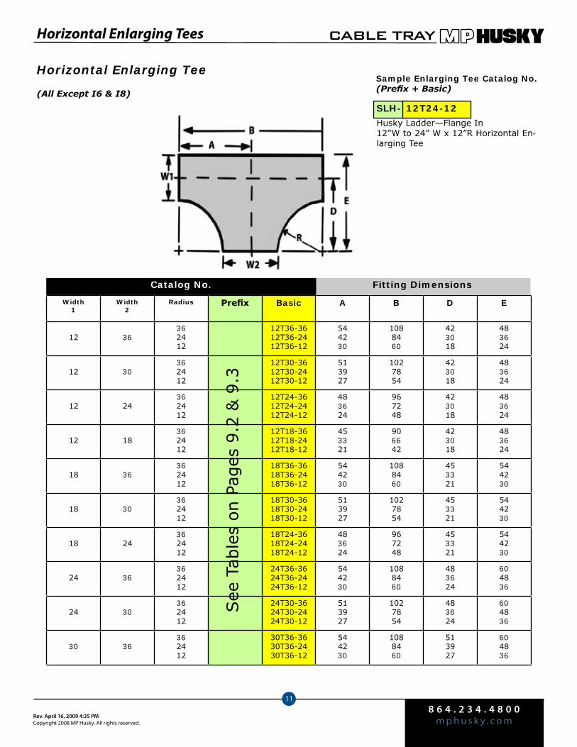
8 6 4 . 2 3 4 . 4 8 0 0m p h u s k y . c o mRev. April 16, 2009 4:35 PM
Copyright 2008 MP Husky. All rights reserved.
CABLE TRAY
11
Horizontal Enlarging Tees
Width1
Width2
Radius Prefix Basic A B D E
12 36362412
12T36-3612T36-2412T36-12
544230
1088460
423018
483624
12 30362412
12T30-3612T30-2412T30-12
513927
1027854
423018
483624
12 24362412
12T24-3612T24-2412T24-12
483624
967248
423018
483624
12 18362412
12T18-3612T18-2412T18-12
453321
906642
423018
483624
18 36362412
18T36-3618T36-2418T36-12
544230
1088460
453321
544230
18 30362412
18T30-3618T30-2418T30-12
513927
1027854
453321
544230
18 24362412
18T24-3618T24-2418T24-12
483624
967248
453321
544230
24 36362412
24T36-3624T36-2424T36-12
544230
1088460
483624
604836
24 30362412
24T30-3624T30-2424T30-12
513927
1027854
483624
604836
30 36362412
30T36-3630T36-2430T36-12
544230
1088460
513927
604836
Horizontal Enlarging Tee
See
Tab
les
on P
ages
9.2
& 9
.3
Fitting Dimensions
Husky Ladder—Flange In12”W to 24” W x 12”R Horizontal En-larging Tee
Sample Enlarging Tee Catalog No.(Prefix + Basic)(All Except I6 & I8)
SLH- 12T24-12
Catalog No.
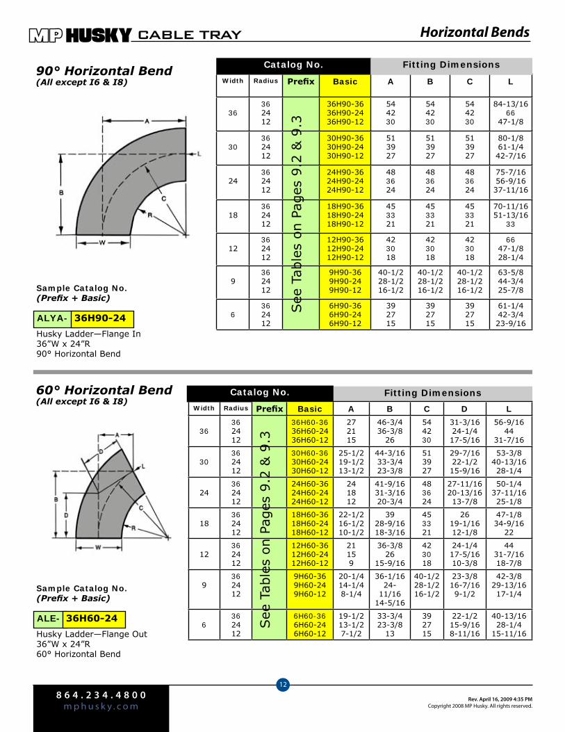
8 6 4 . 2 3 4 . 4 8 0 0m p h u s k y . c o m
Rev. April 16, 2009 4:35 PMCopyright 2008 MP Husky. All rights reserved.
CABLE TRAY
12
Horizontal Bends
Width Radius Prefix Basic A B C L
36362412
36H90-3636H90-2436H90-12
544230
544230
544230
84-13/1666
47-1/8
30362412
30H90-3630H90-2430H90-12
513927
513927
513927
80-1/861-1/442-7/16
24362412
24H90-3624H90-2424H90-12
483624
483624
483624
75-7/1656-9/1637-11/16
18362412
18H90-3618H90-2418H90-12
453321
453321
453321
70-11/1651-13/16
33
12362412
12H90-3612H90-2412H90-12
423018
423018
423018
6647-1/828-1/4
9362412
9H90-369H90-249H90-12
40-1/228-1/216-1/2
40-1/228-1/216-1/2
40-1/228-1/216-1/2
63-5/844-3/425-7/8
6362412
6H90-366H90-246H90-12
392715
392715
392715
61-1/442-3/423-9/16
90° Horizontal Bend(All except I6 & I8)
Catalog No.
60° Horizontal Bend(All except I6 & I8)
See
Tab
les
on P
ages
9.2
& 9
.3
Fitting Dimensions
Sample Catalog No.(Prefix + Basic)
Husky Ladder—Flange In36”W x 24”R 90° Horizontal Bend
Sample Catalog No.(Prefix + Basic)
Husky Ladder—Flange Out36”W x 24”R 60° Horizontal Bend
ALYA- 36H90-24
ALE- 36H60-24
Catalog No. Fitting Dimensions
Width Radius Prefix Basic A B C D L
36362412
36H60-3636H60-2436H60-12
272115
46-3/436-3/8
26
544230
31-3/1624-1/417-5/16
56-9/1644
31-7/16
30362412
30H60-3630H60-2430H60-12
25-1/219-1/213-1/2
44-3/1633-3/423-3/8
513927
29-7/1622-1/215-9/16
53-3/840-13/1628-1/4
24362412
24H60-3624H60-2424H60-12
241812
41-9/1631-3/1620-3/4
483624
27-11/1620-13/1613-7/8
50-1/437-11/1625-1/8
18362412
18H60-3618H60-2418H60-12
22-1/216-1/210-1/2
3928-9/1618-3/16
453321
2619-1/1612-1/8
47-1/834-9/16
22
12362412
12H60-3612H60-2412H60-12
21159
36-3/826
15-9/16
423018
24-1/417-5/1610-3/8
4431-7/1618-7/8
9362412
9H60-369H60-249H60-12
20-1/414-1/48-1/4
36-1/1624-
11/1614-5/16
40-1/228-1/216-1/2
23-3/816-7/169-1/2
42-3/829-13/1617-1/4
6362412
6H60-366H60-246H60-12
19-1/213-1/27-1/2
33-3/423-3/8
13
392715
22-1/215-9/168-11/16
40-13/1628-1/4
15-11/16
See
Tab
les
on P
ages
9.2
& 9
.3
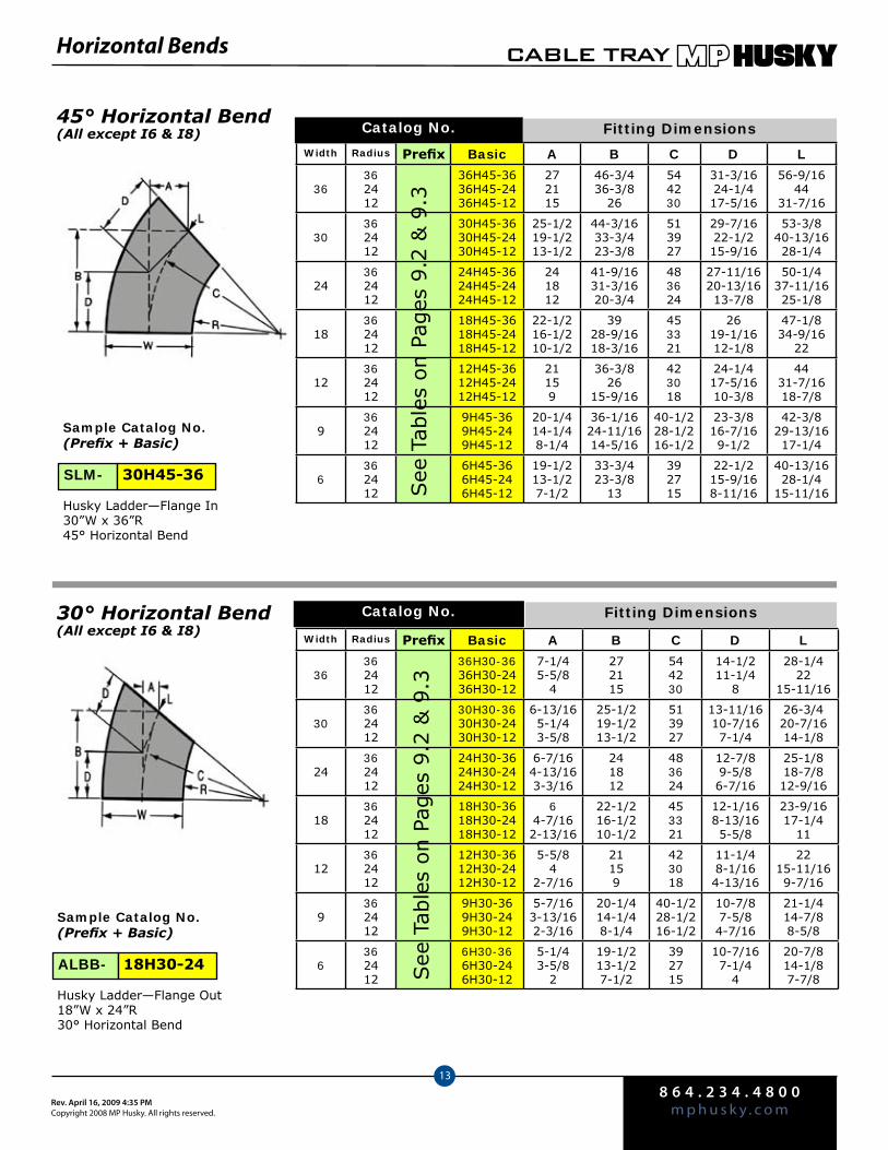
8 6 4 . 2 3 4 . 4 8 0 0m p h u s k y . c o mRev. April 16, 2009 4:35 PM
Copyright 2008 MP Husky. All rights reserved.
CABLE TRAY
13
Fitting DimensionsCatalog No.30° Horizontal Bend(All except I6 & I8)
Horizontal Bends
45° Horizontal Bend(All except I6 & I8) Catalog No. Fitting Dimensions
Sample Catalog No.(Prefix + Basic)
Husky Ladder—Flange In30”W x 36”R 45° Horizontal Bend
Sample Catalog No.(Prefix + Basic)
Husky Ladder—Flange Out18”W x 24”R 30° Horizontal Bend
ALBB- 18H30-24
SLM- 30H45-36
Width Radius Prefix Basic A B C D L
36362412
36H45-3636H45-2436H45-12
272115
46-3/436-3/8
26
544230
31-3/1624-1/417-5/16
56-9/1644
31-7/16
30362412
30H45-3630H45-2430H45-12
25-1/219-1/213-1/2
44-3/1633-3/423-3/8
513927
29-7/1622-1/215-9/16
53-3/840-13/1628-1/4
24362412
24H45-3624H45-2424H45-12
241812
41-9/1631-3/1620-3/4
483624
27-11/1620-13/1613-7/8
50-1/437-11/1625-1/8
18362412
18H45-3618H45-2418H45-12
22-1/216-1/210-1/2
3928-9/1618-3/16
453321
2619-1/1612-1/8
47-1/834-9/16
22
12362412
12H45-3612H45-2412H45-12
21159
36-3/826
15-9/16
423018
24-1/417-5/1610-3/8
4431-7/1618-7/8
9362412
9H45-369H45-249H45-12
20-1/414-1/48-1/4
36-1/1624-11/1614-5/16
40-1/228-1/216-1/2
23-3/816-7/169-1/2
42-3/829-13/1617-1/4
6362412
6H45-366H45-246H45-12
19-1/213-1/27-1/2
33-3/423-3/8
13
392715
22-1/215-9/168-11/16
40-13/1628-1/4
15-11/16See
Tab
les
on P
ages
9.2
& 9
.3
Width Radius Prefix Basic A B C D L
36362412
36H30-3636H30-2436H30-12
7-1/45-5/8
4
272115
544230
14-1/211-1/4
8
28-1/422
15-11/16
30362412
30H30-3630H30-2430H30-12
6-13/165-1/43-5/8
25-1/219-1/213-1/2
513927
13-11/1610-7/167-1/4
26-3/420-7/1614-1/8
24362412
24H30-3624H30-2424H30-12
6-7/164-13/163-3/16
241812
483624
12-7/89-5/86-7/16
25-1/818-7/812-9/16
18362412
18H30-3618H30-2418H30-12
64-7/162-13/16
22-1/216-1/210-1/2
453321
12-1/168-13/165-5/8
23-9/1617-1/4
11
12362412
12H30-3612H30-2412H30-12
5-5/84
2-7/16
21159
423018
11-1/48-1/164-13/16
2215-11/169-7/16
9362412
9H30-369H30-249H30-12
5-7/163-13/162-3/16
20-1/414-1/48-1/4
40-1/228-1/216-1/2
10-7/87-5/84-7/16
21-1/414-7/88-5/8
6362412
6H30-366H30-246H30-12
5-1/43-5/8
2
19-1/213-1/27-1/2
392715
10-7/167-1/4
4
20-7/814-1/87-7/8S
ee T
able
s on P
ages
9.2
& 9
.3
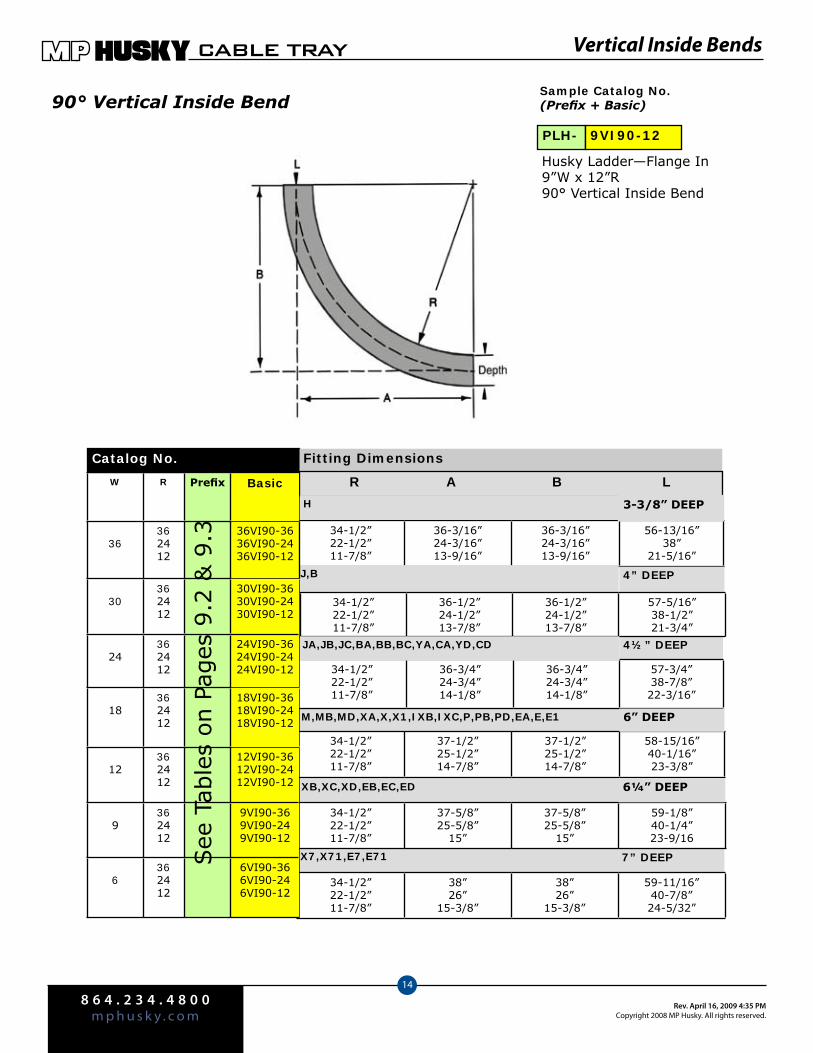
8 6 4 . 2 3 4 . 4 8 0 0m p h u s k y . c o m
Rev. April 16, 2009 4:35 PMCopyright 2008 MP Husky. All rights reserved.
CABLE TRAY
14
Vertical Inside Bends
90° Vertical Inside BendSample Catalog No.(Prefix + Basic)
Husky Ladder—Flange In 9”W x 12”R 90° Vertical Inside Bend
PLH- 9VI90-12
4½” DEEP
Catalog No.
M,MB,MD,XA,X,X1,IXB,IXC,P,PB,PD,EA,E,E1
XB,XC,XD,EB,EC,ED
X7,X71,E7,E71 7” DEEP
34-1/2”22-1/2”11-7/8”
36-3/16”24-3/16”13-9/16”
36-3/16”24-3/16”13-9/16”
56-13/16”38”
21-5/16”
J,B 4” DEEP
34-1/2”22-1/2”11-7/8”
36-1/2”24-1/2”13-7/8”
36-1/2”24-1/2”13-7/8”
57-5/16”38-1/2”21-3/4”
34-1/2”22-1/2”11-7/8”
36-3/4”24-3/4”14-1/8”
36-3/4”24-3/4”14-1/8”
57-3/4”38-7/8”22-3/16”
34-1/2”22-1/2”11-7/8”
37-1/2”25-1/2”14-7/8”
37-1/2”25-1/2”14-7/8”
58-15/16”40-1/16”23-3/8”
34-1/2”22-1/2”11-7/8”
37-5/8”25-5/8”
15”
37-5/8”25-5/8”
15”
59-1/8”40-1/4”23-9/16
Fitting Dimensions
34-1/2”22-1/2”11-7/8”
38”26”
15-3/8”
38”26”
15-3/8”
59-11/16”40-7/8”24-5/32”
R A B L
H 3-3/8” DEEP
JA,JB,JC,BA,BB,BC,YA,CA,YD,CD
6” DEEP
6¼” DEEP
W R Prefix Basic
36362412
36VI90-3636VI90-2436VI90-12
30362412
30VI90-3630VI90-2430VI90-12
24362412
24VI90-3624VI90-2424VI90-12
18362412
18VI90-3618VI90-2418VI90-12
12362412
12VI90-3612VI90-2412VI90-12
9362412
9VI90-369VI90-249VI90-12
6362412
6VI90-366VI90-246VI90-12
See
Tab
les
on P
ages
9.2
& 9
.3
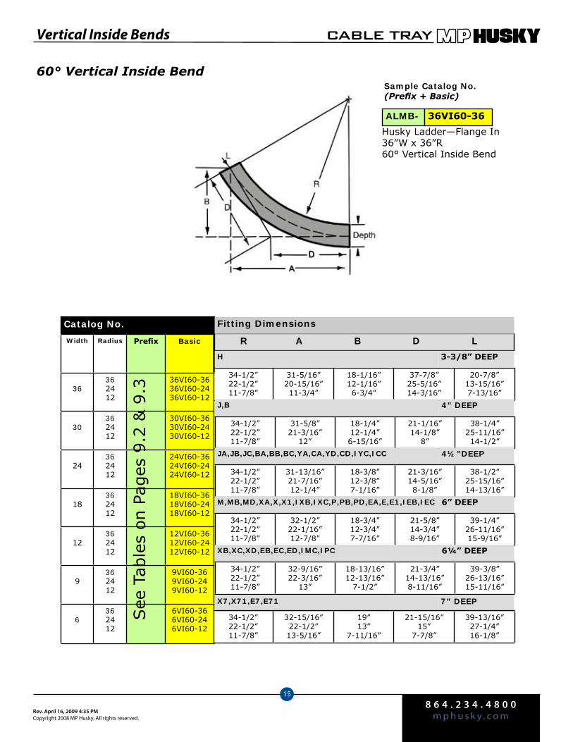
8 6 4 . 2 3 4 . 4 8 0 0m p h u s k y . c o mRev. April 16, 2009 4:35 PM
Copyright 2008 MP Husky. All rights reserved.
CABLE TRAY
15
60° Vertical Inside Bend
Vertical Inside Bends
Sample Catalog No.(Prefix + Basic)
Husky Ladder—Flange In 36”W x 36”R 60° Vertical Inside Bend
ALMB- 36VI60-36
R A B D L
34-1/2”22-1/2”11-7/8”
31-5/16”20-15/16”11-3/4”
18-1/16”12-1/16”6-3/4”
37-7/8”25-5/16”14-3/16”
20-7/8”13-15/16”7-13/16”
H 3-3/8” DEEP
4” DEEP
34-1/2”22-1/2”11-7/8”
31-5/8”21-3/16”
12”
18-1/4”12-1/4”6-15/16”
21-1/16”14-1/8”
8”
38-1/4”25-11/16”14-1/2”
JA,JB,JC,BA,BB,BC,YA,CA,YD,CD,IYC,ICC 4½”DEEP
34-1/2”22-1/2”11-7/8”
31-13/16”21-7/16”12-1/4”
18-3/8”12-3/8”7-1/16”
21-3/16”14-5/16”8-1/8”
38-1/2”25-15/16”14-13/16”
M,MB,MD,XA,X,X1,IXB,IXC,P,PB,PD,EA,E,E1,IEB,IEC 6” DEEP
34-1/2”22-1/2”11-7/8”
32-1/2”22-1/16”12-7/8”
18-3/4”12-3/4”7-7/16”
21-5/8”14-3/4”8-9/16”
39-1/4”26-11/16”15-9/16”
XB,XC,XD,EB,EC,ED,IMC,IPC 6¼” DEEP
34-1/2”22-1/2”11-7/8”
32-9/16”22-3/16”
13”
18-13/16”12-13/16”
7-1/2”
21-3/4”14-13/16”8-11/16”
39-3/8”26-13/16”15-11/16”
Catalog No. Fitting Dimensions
X7,X71,E7,E71 7” DEEP
34-1/2”22-1/2”11-7/8”
32-15/16”22-1/2”13-5/16”
19”13”
7-11/16”
21-15/16”15”
7-7/8”
39-13/16”27-1/4”16-1/8”
Width Radius Prefix Basic
36362412
36VI60-3636VI60-2436VI60-12
30362412
30VI60-3630VI60-2430VI60-12
24362412
24VI60-3624VI60-2424VI60-12
18362412
18VI60-3618VI60-2418VI60-12
12362412
12VI60-3612VI60-2412VI60-12
9362412
9VI60-369VI60-249VI60-12
6362412
6VI60-366VI60-246VI60-12
See
Tab
les
on P
ages
9.2
& 9
.3
J,B
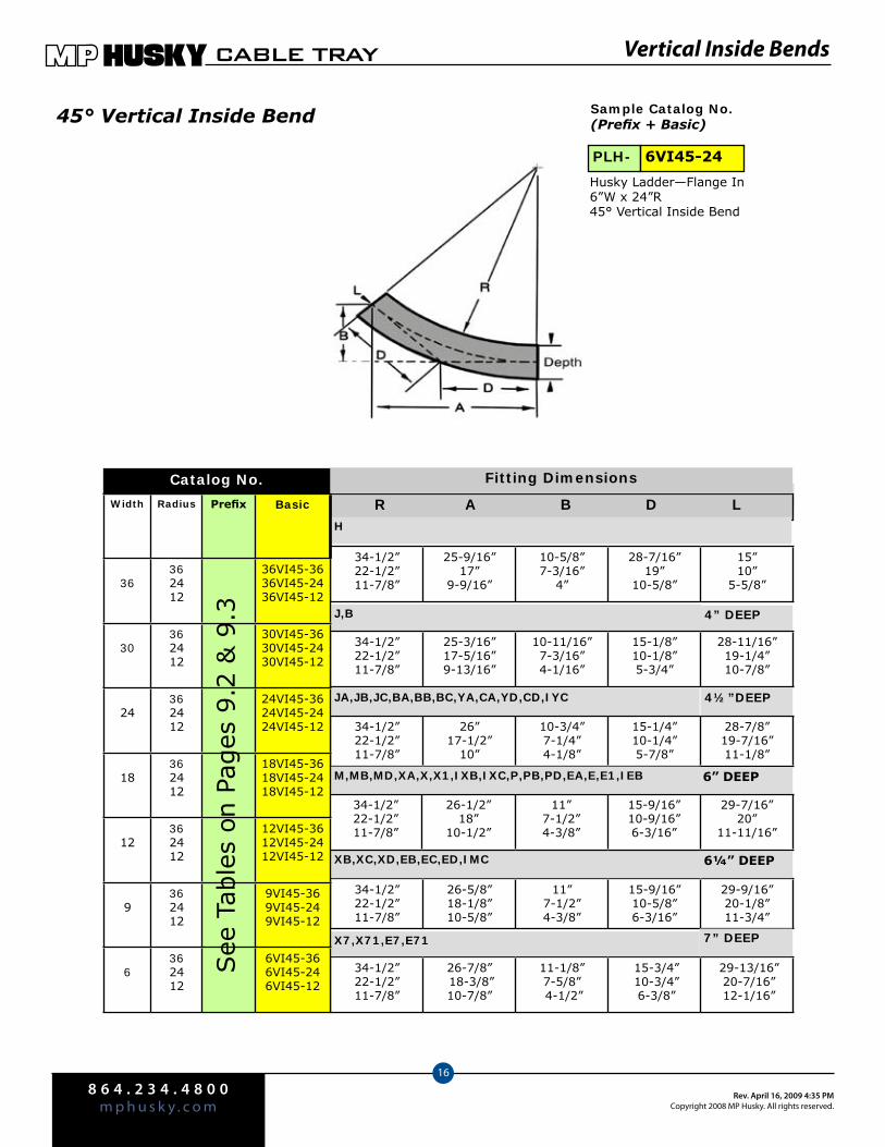
8 6 4 . 2 3 4 . 4 8 0 0m p h u s k y . c o m
Rev. April 16, 2009 4:35 PMCopyright 2008 MP Husky. All rights reserved.
CABLE TRAY
16
Vertical Inside Bends
45° Vertical Inside Bend
3 - 3 / 8 ”
Sample Catalog No.(Prefix + Basic)
Husky Ladder—Flange In 6”W x 24”R 45° Vertical Inside Bend
PLH- 6VI45-24
Catalog No.
R A B D L
34-1/2”22-1/2”11-7/8”
25-9/16”17”
9-9/16”
10-5/8”7-3/16”
4”
28-7/16”19”
10-5/8”
15”10”
5-5/8”
H
J,B 4” DEEP
34-1/2”22-1/2”11-7/8”
25-3/16”17-5/16”9-13/16”
10-11/16”7-3/16”4-1/16”
15-1/8”10-1/8”5-3/4”
28-11/16”19-1/4”10-7/8”
JA,JB,JC,BA,BB,BC,YA,CA,YD,CD,IYC 4½”DEEP
34-1/2”22-1/2”11-7/8”
26”17-1/2”
10”
10-3/4”7-1/4”4-1/8”
15-1/4”10-1/4”5-7/8”
28-7/8”19-7/16”11-1/8”
M,MB,MD,XA,X,X1,IXB,IXC,P,PB,PD,EA,E,E1,IEB 6” DEEP
34-1/2”22-1/2”11-7/8”
26-5/8”18-1/8”10-5/8”
11”7-1/2”4-3/8”
15-9/16”10-5/8”6-3/16”
29-9/16”20-1/8”11-3/4”
XB,XC,XD,EB,EC,ED,IMC 6¼” DEEP
34-1/2”22-1/2”11-7/8”
26-7/8” 18-3/8”10-7/8”
11-1/8”7-5/8” 4-1/2”
15-3/4” 10-3/4” 6-3/8”
29-13/16” 20-7/16” 12-1/16”
Fitting Dimensions
34-1/2”22-1/2”11-7/8”
26-1/2”18”
10-1/2”
11”7-1/2”4-3/8”
15-9/16”10-9/16”6-3/16”
29-7/16”20”
11-11/16”
7” DEEPX7,X71,E7,E71
Width Radius Prefix Basic
36362412
36VI45-3636VI45-2436VI45-12
30362412
30VI45-3630VI45-2430VI45-12
24362412
24VI45-3624VI45-2424VI45-12
18362412
18VI45-3618VI45-2418VI45-12
12362412
12VI45-3612VI45-2412VI45-12
9362412
9VI45-369VI45-249VI45-12
6362412
6VI45-366VI45-246VI45-12
See
Tab
les
on P
ages
9.2
& 9
.3
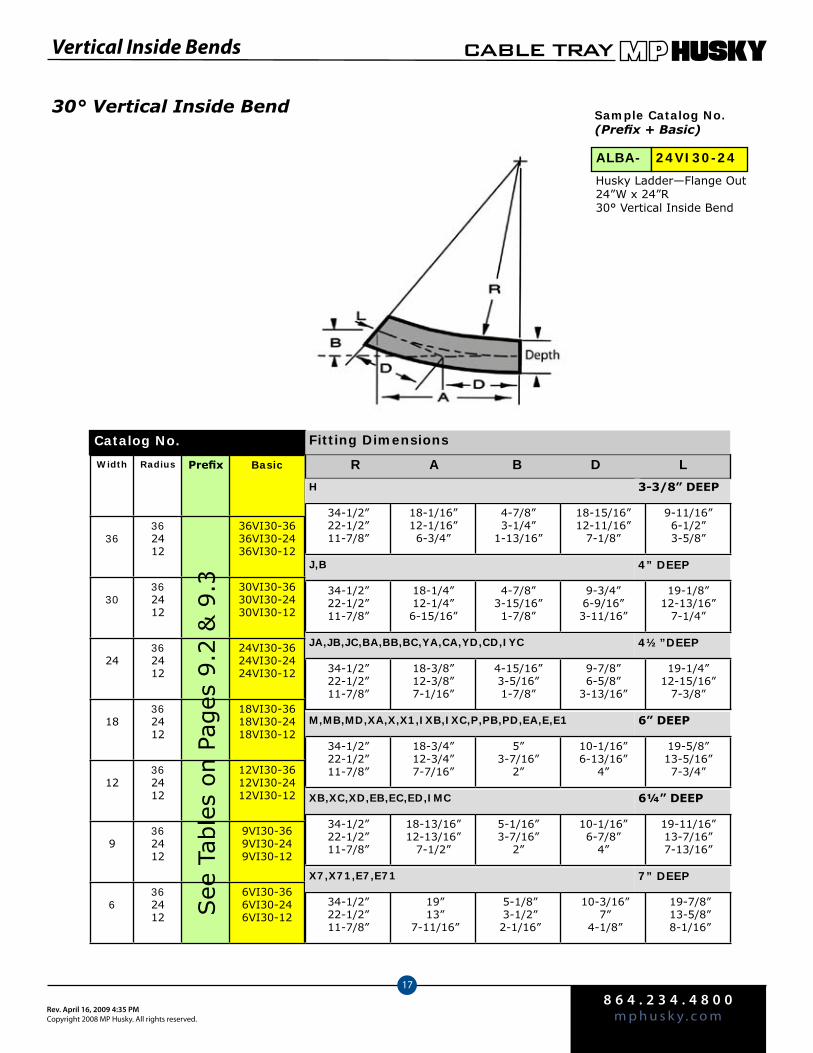
8 6 4 . 2 3 4 . 4 8 0 0m p h u s k y . c o mRev. April 16, 2009 4:35 PM
Copyright 2008 MP Husky. All rights reserved.
CABLE TRAY
17
Vertical Inside Bends
30° Vertical Inside Bend
R A B D L
34-1/2”22-1/2”11-7/8”
18-1/16”12-1/16”6-3/4”
4-7/8”3-1/4”
1-13/16”
18-15/16”12-11/16”
7-1/8”
9-11/16”6-1/2”3-5/8”
H 3-3/8” DEEP
J,B 4” DEEP
34-1/2”22-1/2”11-7/8”
18-1/4”12-1/4”6-15/16”
4-7/8”3-15/16”1-7/8”
9-3/4”6-9/16”3-11/16”
19-1/8”12-13/16”
7-1/4”
JA,JB,JC,BA,BB,BC,YA,CA,YD,CD,IYC 4½”DEEP
34-1/2”22-1/2”11-7/8”
18-3/8”12-3/8”7-1/16”
4-15/16”3-5/16”1-7/8”
9-7/8”6-5/8”
3-13/16”
19-1/4”12-15/16”
7-3/8”
M,MB,MD,XA,X,X1,IXB,IXC,P,PB,PD,EA,E,E1 6” DEEP
34-1/2”22-1/2”11-7/8”
18-3/4”12-3/4”7-7/16”
5”3-7/16”
2”
10-1/16”6-13/16”
4”
19-5/8”13-5/16”7-3/4”
XB,XC,XD,EB,EC,ED,IMC 6¼” DEEP
34-1/2”22-1/2”11-7/8”
18-13/16”12-13/16”
7-1/2”
5-1/16”3-7/16”
2”
10-1/16”6-7/8”
4”
19-11/16”13-7/16”7-13/16”
Catalog No.
Width Radius Prefix Basic
36362412
36VI30-3636VI30-2436VI30-12
30362412
30VI30-3630VI30-2430VI30-12
24362412
24VI30-3624VI30-2424VI30-12
18362412
18VI30-3618VI30-2418VI30-12
12362412
12VI30-3612VI30-2412VI30-12
9362412
9VI30-369VI30-249VI30-12
6362412
6VI30-366VI30-246VI30-12S
ee T
able
s on P
ages
9.2
& 9
.3
Fitting Dimensions
Sample Catalog No.(Prefix + Basic)
ALBA- 24VI30-24
34-1/2”22-1/2”11-7/8”
19” 13”
7-11/16”
5-1/8” 3-1/2” 2-1/16”
10-3/16” 7”
4-1/8”
19-7/8” 13-5/8” 8-1/16”
7” DEEPX7,X71,E7,E71
Husky Ladder—Flange Out 24”W x 24”R 30° Vertical Inside Bend
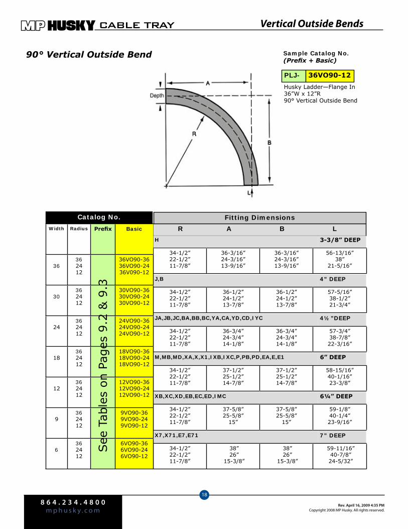
8 6 4 . 2 3 4 . 4 8 0 0m p h u s k y . c o m
Rev. April 16, 2009 4:35 PMCopyright 2008 MP Husky. All rights reserved.
CABLE TRAY
18
Vertical Outside Bends
90° Vertical Outside Bend
See
Tab
les
on P
ages
9.2
& 9
.3
Sample Catalog No.(Prefix + Basic)
Husky Ladder—Flange In 36”W x 12”R 90° Vertical Outside Bend
PLJ- 36VO90-12
Catalog No.
R A B L
34-1/2”22-1/2”11-7/8”
36-3/16”24-3/16”13-9/16”
36-3/16”24-3/16”13-9/16”
56-13/16”38”
21-5/16”
H 3-3/8” DEEP
J,B 4” DEEP
34-1/2”22-1/2”11-7/8”
36-1/2”24-1/2”13-7/8”
36-1/2”24-1/2”13-7/8”
57-5/16”38-1/2”21-3/4”
JA,JB,JC,BA,BB,BC,YA,CA,YD,CD,IYC 4½”DEEP
34-1/2”22-1/2”11-7/8”
36-3/4”24-3/4”14-1/8”
36-3/4”24-3/4”14-1/8”
57-3/4”38-7/8”22-3/16”
M,MB,MD,XA,X,X1,IXB,IXC,P,PB,PD,EA,E,E1 6” DEEP
34-1/2”22-1/2”11-7/8”
37-1/2”25-1/2”14-7/8”
37-1/2”25-1/2”14-7/8”
58-15/16”40-1/16”23-3/8”
XB,XC,XD,EB,EC,ED,IMC 6¼” DEEP
34-1/2”22-1/2”11-7/8”
37-5/8”25-5/8”
15”
37-5/8”25-5/8”
15”
59-1/8”40-1/4”23-9/16”
Fitting Dimensions
7” DEEPX7,X71,E7,E71
34-1/2”22-1/2”11-7/8”
38” 26”
15-3/8”
38” 26”
15-3/8”
59-11/16” 40-7/8” 24-5/32”
Width Radius Prefix Basic
36362412
36VO90-3636VO90-2436V090-12
30362412
30VO90-3630VO90-2430VO90-12
24362412
24VO90-3624VO90-2424VO90-12
18362412
18VO90-3618VO90-2418VO90-12
12362412
12VO90-3612VO90-2412VO90-12
9362412
9VO90-369VO90-249VO90-12
6362412
6VO90-366VO90-246VO90-12
See
Tab
les
on P
ages
9.2
& 9
.3

8 6 4 . 2 3 4 . 4 8 0 0m p h u s k y . c o mRev. April 16, 2009 4:35 PM
Copyright 2008 MP Husky. All rights reserved.
CABLE TRAY
19
Vertical Outside Bends
60° Vertical Outside Bend Sample Catalog No.(Prefix + Basic)
ALCA- 18VO60-24
3-3/8” DEEP
34-1/2”22-1/2”11-7/8”
31-5/8”21-3/16”
12”
18-1/4”12-1/4”6-15/16”
21-1/16”14-1/8”
8”
38-1/4”25-11/16”14-1/2”
4½”DEEP
R A B D L
34-1/2”22-1/2”11-7/8”
31-5/16”20-15/16”11-3/4”
18-1/16”12-1/16”6-3/4”
37-7/8”25-5/16”14-3/16”
20-7/8”13-15/16”7-13/16”
H
J,B 4” DEEP
JA,JB,JC,BA,BB,BC,YA,CA,YD,CD,IYC
34-1/2”22-1/2”11-7/8”
31-13/16”12-7/16”12-1/4”
18-3/8”12-3/8”7-1/16”
21-3/16”14-5/16”8-1/8”
38-1/2”25-15/16”14-13/16”
M,MB,MD,XA,X,X1,IXB,IXC,P,PB,PD,EA,E,E1 6” DEEP
34-1/2”22-1/2”11-7/8”
32-1/2”22-1/16”12-7/8”
18-3/4”12-3/4”7-7/16”
21-5/8”14-3/4”8-9/16”
39-1/4”26-11/16”15-9/16”
XB,XC,XD,EB,EC,ED,IMC 6¼” DEEP
34-1/2”22-1/2”11-7/8”
32-9/16”22-3/16”
13”
18-13/16”12-13/16”
7-1/2”
21-3/4”14-13/16”8-11/16”
39-3/8”26-13/1615-11/16”
Catalog No.
Width Radius Prefix Basic
36362412
36VO60-3636VO60-2436VO60-12
30362412
30VO60-3630VO60-2430VO60-12
24362412
24VO60-3624VO60-2424VO60-12
18362412
18VO60-3618VO60-2418VO60-12
12362412
12VO60-3612VO60-2412VO60-12
9362412
9VO60-369VO60-249VO60-12
6362412
6VO60-366VO60-246VO60-12
See
Tab
les
on P
ages
9.2
& 9
.3
Fitting Dimensions
34-1/2”22-1/2”11-7/8”
32-15/16” 22-1/2” 13-5/16”
19” 13”
7-11/16”
21-15/16” 15”
7-7/8”
39-13/16” 27-1/4” 16-1/8”
7” DEEPX7,X71,E7,E71
Husky Ladder—Flange Out 18”W x 24”R 60° Vertical Outside Bend
For more information or to order, call 1-800-277-4810 or visit www.mphusky.com.
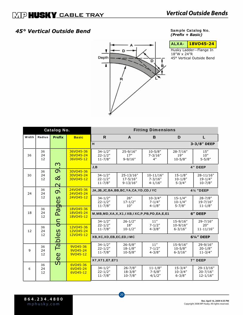
8 6 4 . 2 3 4 . 4 8 0 0m p h u s k y . c o m
Rev. April 16, 2009 4:35 PMCopyright 2008 MP Husky. All rights reserved.
CABLE TRAY
20
Vertical Outside Bends
45° Vertical Outside Bend Sample Catalog No.(Prefix + Basic)
Husky Ladder—Flange In 18”W x 24”R 45° Vertical Outside Bend
ALXA- 18VO45-24
Catalog No.
Width Radius Prefix Basic
36362412
36VO45-3636VO45-2436V045-12
30362412
30VO45-3630VO45-2430VO45-12
24362412
24VO45-3624VO45-2424VO45-12
18362412
18VO45-3618VO45-2418VO45-12
12362412
12VO45-3612VO45-2412VO45-12
9362412
9VO45-369VO45-249VO45-12
6362412
6VO45-366VO45-246VO45-12
R A B D L
34-1/2”22-1/2”11-7/8”
25-9/16”17”
9-9/16”
10-5/8”7-3/16”
4”
28-7/16”19”
10-5/8”
15”10”
5-5/8”
H 3-3/8” DEEP
J,B 4” DEEP
34-1/2”22-1/2”11-7/8”
25-13/16”17-5/16”9-13/16”
10-11/16”7-3/16”4-1/16”
15-1/8”10-1/8”5-3/4”
28-11/16”19-1/4”10-7/8”
JA,JB,JC,BA,BB,BC,YA,CA,YD,CD,IYC 4½”DEEP
34-1/2”22-1/2”11-7/8”
26”17-1/2”
10”
10-3/4”7-1/4”4-1/8”
15-1/4”10-1/4”5-7/8”
28-7/8”19-7/16”11-1/8”
M,MB,MD,XA,X,X1,IXB,IXC,P,PB,PD,EA,E,E1 6” DEEP
34-1/2”22-1/2”11-7/8”
26-1/2”18”
10-1/2”
11”7-1/2”4-3/8”
15-9/16”10-9/16”6-3/16”
29-7/16”20”
11-11/16”
XB,XC,XD,EB,EC,ED,IMC 6¼” DEEP
34-1/2”22-1/2”11-7/8”
26-5/8”18-1/8”10-5/8”
11”7-1/2”4-3/8”
15-9/16”10-5/8”6-3/16”
29-9/16”20-1/8”11-3/4”
See
Tab
les
on P
ages
9.2
& 9
.3
Fitting Dimensions
34-1/2”22-1/2”11-7/8”
26-7/8” 18-3/8” 10-7/8”
11-1/8” 7-5/8” 4/1/2”
15-3/4” 10-3/4” 6-3/8”
29-13/16” 20-7/16” 12-1/16”
7” DEEPX7,X71,E7,E71
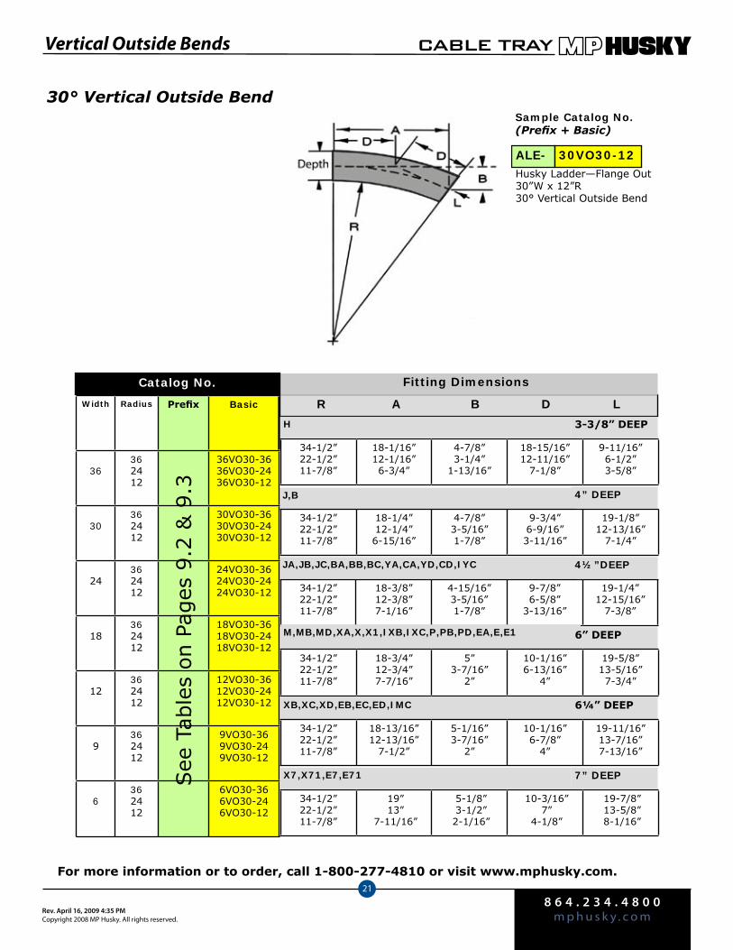
8 6 4 . 2 3 4 . 4 8 0 0m p h u s k y . c o mRev. April 16, 2009 4:35 PM
Copyright 2008 MP Husky. All rights reserved.
CABLE TRAY
21
Vertical Outside Bends
30° Vertical Outside BendSample Catalog No.(Prefix + Basic)
ALE- 30VO30-12
R A B D L
34-1/2”22-1/2”11-7/8”
18-1/16”12-1/16”6-3/4”
4-7/8”3-1/4”
1-13/16”
18-15/16”12-11/16”
7-1/8”
9-11/16”6-1/2”3-5/8”
H 3-3/8” DEEP
J,B 4” DEEP
34-1/2”22-1/2”11-7/8”
18-1/4”12-1/4”6-15/16”
4-7/8”3-5/16”1-7/8”
9-3/4”6-9/16”3-11/16”
19-1/8”12-13/16”
7-1/4”
JA,JB,JC,BA,BB,BC,YA,CA,YD,CD,IYC 4½”DEEP
34-1/2”22-1/2”11-7/8”
18-3/8”12-3/8”7-1/16”
4-15/16”3-5/16”1-7/8”
9-7/8”6-5/8”
3-13/16”
19-1/4”12-15/16”
7-3/8”
M,MB,MD,XA,X,X1,IXB,IXC,P,PB,PD,EA,E,E1 6” DEEP
34-1/2”22-1/2”11-7/8”
18-3/4”12-3/4”7-7/16”
5”3-7/16”
2”
10-1/16”6-13/16”
4”
19-5/8”13-5/16”7-3/4”
XB,XC,XD,EB,EC,ED,IMC 6¼” DEEP
34-1/2”22-1/2”11-7/8”
18-13/16”12-13/16”
7-1/2”
5-1/16”3-7/16”
2”
10-1/16”6-7/8”
4”
19-11/16”13-7/16”7-13/16”
Width Radius Prefix Basic
36362412
36VO30-3636VO30-2436VO30-12
30362412
30VO30-3630VO30-2430VO30-12
24362412
24VO30-3624VO30-2424VO30-12
18362412
18VO30-3618VO30-2418VO30-12
12362412
12VO30-3612VO30-2412VO30-12
9362412
9VO30-369VO30-249VO30-12
6362412
6VO30-366VO30-246VO30-12
Fitting Dimensions
See
Tab
les
on P
ages
9.2
& 9
.3
34-1/2”22-1/2”11-7/8”
19” 13”
7-11/16”
5-1/8” 3-1/2” 2-1/16”
10-3/16” 7”
4-1/8”
19-7/8” 13-5/8” 8-1/16”
7” DEEPX7,X71,E7,E71
Catalog No.
Husky Ladder—Flange Out 30”W x 12”R 30° Vertical Outside Bend
For more information or to order, call 1-800-277-4810 or visit www.mphusky.com.

8 6 4 . 2 3 4 . 4 8 0 0m p h u s k y . c o m
Rev. April 16, 2009 4:35 PMCopyright 2008 MP Husky. All rights reserved.
CABLE TRAY
22
Vertical Cable Supports
Vertical Cable SupportsSample Catalog No.(Prefix + Basic)
Husky Ladder Flange In 36”W x 36”R Vertical Cable Supports
36VS-36ALMB-
Catalog No.
Width Radius Prefix Basic
36362412
36VS-3636VS-2436VS-12
30362412
30VS-3630VS-2430VS-12
24362412
24VS-3624VS-2424VS-12
18362412
18VS-3618VS-2418VS-12
12362412
12VS-3612VS-2412VS-12
9362412
9VS-369VS-249VS-12
6362412
6VS-366VS-246VS-12
R A B/C L
34-1/2”22-1/2”11-7/8”
36-3/16”24-3/16”13-9/16”
36-3/16”24-3/16”13-9/16”
56-13/16”38”
21-5/16”
H 3-3/8” DEEP
J,B 4” DEEP
34-1/2”22-1/2”11-7/8”
36-1/2”24-1/2”13-7/8”
36-1/2”24-1/2”13-7/8”
57-5/16”38-1/2”21-3/4”
JA,JB,JC,BA,BB,BC,YA,CA,YD,CD,IYC 4½”DEEP
34-1/2”22-1/2”11-7/8”
36-3/4”24-3/4”14-1/8”
36-3/4”24-3/4”14-1/8”
57-3/4”38-7/8”22-3/16”
M,MB,MD,XA,X,X1,IXB,IXC,P,PB,PD,EA,E,E1 6” DEEP
34-1/2”22-1/2”11-7/8”
37-1/2”25-1/2”14-7/8”
37-1/2”25-1/2”14-7/8”
58-15/16”40-1/16”23-3/8”
XB,XC,XD,EB,EC,ED,IMC 6¼” DEEP
34-1/2”22-1/2”11-7/8”
37-5/8”25-5/8”
15”
37-5/8”25-5/8”
15”
59-1/8”40-1/4”23-9/16”
See
Tab
les
on P
ages
9.2
& 9
.3
Fitting Dimensions
7” DEEPX7,X71,E7,E71
34-1/2”22-1/2”11-7/8”
38” 26”
15-3/8”
38” 26”
15-3/8”
59-11/16” 40-7/8” 24-5/32”
Cable Support HookCat No. SH-38
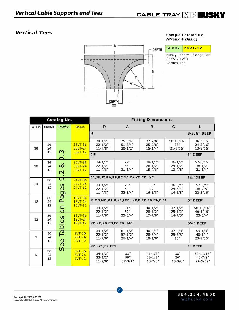
8 6 4 . 2 3 4 . 4 8 0 0m p h u s k y . c o mRev. April 16, 2009 4:35 PM
Copyright 2008 MP Husky. All rights reserved.
CABLE TRAY
23
Vertical Cable Supports and Tees
Vertical Tees Sample Catalog No.(Prefix + Basic)
24VT-12SLPD-
Husky Ladder—Flange Out 24”W x 12”R Vertical Tee
R A B C L
34-1/2”22-1/2”11-7/8”
75-3/4”51-3/4”30-1/2”
37-7/8”25-7/8”15-1/4”
56-13/16”38”
21-5/16”
36-3/16”24-3/16”13-9/16”
H 3-3/8” DEEP
J,B 4” DEEP
34-1/2”22-1/2”11-7/8”
77”53”
31-3/4”
38-1/2”26-1/2”15-7/8”
36-1/2”24-1/2”13-7/8”
57-5/16”38-1/2”21-3/4”
JA,JB,JC,BA,BB,BC,YA,CA,YD,CD,IYC 4½”DEEP
34-1/2”22-1/2”11-7/8”
78”54”
32-3/4”
39”27”
16-3/8”
36-3/4”24-3/4”14-1/8”
57-3/4”38-7/8”22-3/16”
M,MB,MD,XA,X,X1,IXB,IXC,P,PB,PD,EA,E,E1 6” DEEP
34-1/2”22-1/2”11-7/8”
81”57”
35-3/4”
40-1/2”28-1/2”17-7/8”
37-1/2”25-1/2”14-7/8”
58-15/16”40-1/16”23-3/4”
XB,XC,XD,EB,EC,ED,IMC 6¼” DEEP
34-1/2”22-1/2”11-7/8”
81-1/2”57-1/2”36-1/4”
40-3/4”28-3/4”18-1/8”
37-5/8”25-5/8”
15”
59-1/8”40-1/4”23-9/16”
Catalog No.
Width Radius Prefix Basic
36362412
36VT-3636VT-2436VT-12
30362412
30VT-3630VT-2430VT-12
24362412
24VT-3624VT-2424VT-12
18362412
18VT-3618VT-2418VT-12
12362412
12VT-3612VT-2412VT-12
9362412
9VT-369VT-249VT-12
6362412
6VT-366VT-246VT-12
See
Tab
les
on P
ages
9.2
& 9
.3
Fitting Dimensions
7” DEEPX7,X71,E7,E71
34-1/2”22-1/2”11-7/8”
83” 59”
37-3/4”
41-1/2” 29-1/2” 18-7/8”
38” 26”
15-3/8”
59-11/16” 40-7/8” 24-5/32”

8 6 4 . 2 3 4 . 4 8 0 0m p h u s k y . c o m
Rev. April 16, 2009 4:35 PMCopyright 2008 MP Husky. All rights reserved.
CABLE TRAY
24
Flange In, Flange Out, Trough Reducers
Husky Ladder Reducer—Flange In Husky Ladder Reducer—Flange Out
W W1 Prefix Basic Prefix Basic Prefix Basic A/B C
36
3024181296
36R3036R2436R1836R1236R936R6
36RL3036RL2436RL1836RL1236RL936RL6
36RR3036RR2436RR1836RR1236RR936RR6
36912
13-1/215
61218242730
30
24181296
30R2430R1830R1230R930R6
30RL2430RL1830RL1230RL930RL6
30RR2430RR1830RR1230RR930RR6
369
10-1/212
612182124
24181296
24R1824R1224R924R6
24RL1824RL1224RL924RL6
24RR1824RR1224RR924RR6
36
7-1/29
6121518
181296
18R1218R918R6
18RL1218RL918RL6
18RR1218RR918RR6
34-1/2
6
6912
12 96
12R912R6
12RL912RL6
12RR912RR6
1-1/23
36
9 6 9R6 9RL6 9RR6 1-1/2 3
WidthConcentricCatalog No.
Reducers for Husky Ladder Trays
Left HandCatalog No.
Right HandCatalog No.
See
Tab
les
on P
ages
9.2
& 9
.3
See
Tab
les
on P
ages
9.2
& 9
.3
See
Tab
les
on P
ages
9.2
& 9
.3
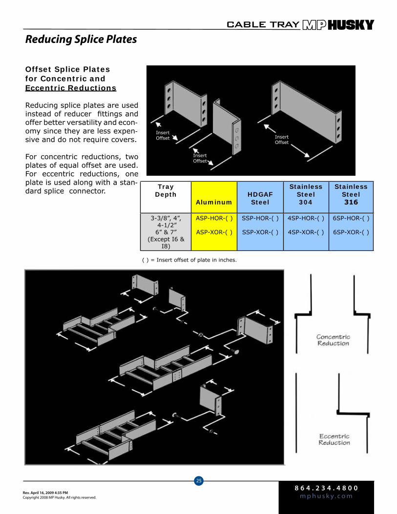
8 6 4 . 2 3 4 . 4 8 0 0m p h u s k y . c o mRev. April 16, 2009 4:35 PM
Copyright 2008 MP Husky. All rights reserved.
CABLE TRAY
25
Reducing Splice Plates
Tray Depth
AluminumHDGAF Steel
Stainless Steel304
Stainless Steel316
3-3/8”, 4”, 4-1/2”6” & 7”
(Except I6 & I8)
ASP-HOR-( )
ASP-XOR-( )
SSP-HOR-( )
SSP-XOR-( )
4SP-HOR-( )
4SP-XOR-( )
6SP-HOR-( )
6SP-XOR-( )
Offset Splice Plates for Concentric and Eccentric Reductions
Reducing splice plates are used instead of reducer fittings and offer better versatility and econ-omy since they are less expen-sive and do not require covers.
For concentric reductions, two plates of equal offset are used. For eccentric reductions, one plate is used along with a stan-dard splice connector.
( ) = Insert offset of plate in inches.
InsertOffset
InsertOffset
InsertOffset

10.1
For more information or to order, call 1-800-277-4810 or visit www.mphusky.com.
Accessories, Splices and Connectors
Splices and Connectors Pgs. 11.2-11.6Misc. Accessories Pgs. 11.6-11.8Ground Connectors Pg. 11.9Separators Pgs 11.10-11.11
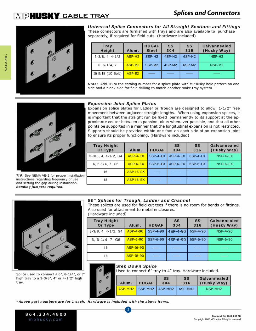
ACC
eSSo
rieS
8 6 4 . 2 3 4 . 4 8 0 0m p h u s k y . c o m
Rev. April 16, 2009 4:37 PMCopyright 2008 MP Husky. All rights reserved.
CABLE TRAY
2
Splices and Connectors
Universal Splice Connectors for All Straight Sections and FittingsThese connectors are furnished with trays and are also available to purchase separately, if required for field cuts. (Hardware included)
Tray Height Alum.
HDGAFSteel
SS304
SS316
Galvannealed(Husky Way)
3-3/8, 4, 4-1/2 ASP-H2 SSP-H2 4SP-H2 6SP-H2 NSP-H2
6, 6-1/4, 7 ASP-M2 SSP-M2 4SP-M2 6SP-M2 NSP-M2
I6 & I8 (10 Bolt) ASP-E2 —— —— —— ——
Expansion Joint Splice PlatesExpansion splice plates for Ladder or Trough are designed to allow 1-1/2” free movement between adjacent straight lengths. When using expansion splices, it is important that the straight run be fixed permanently to its support at the ap-proximate center between expansion joints whenever possible, and that all other points be supported in a manner that the longitudinal expansion is not restricted. Supports should be provided within one foot on each side of an expansion joint to ensure its proper functioning. (Hardware included)
Tray HeightOr Type Alum. HDGAF
SS304
SS316
Galvannealed(Husky Way)
3-3/8, 4, 4-1/2, G4 ASP-4-EX SSP-4-EX 4SP-4-EX 6SP-4-EX NSP-4-EX
6, 6-1/4, 7, G6 ASP-6-EX SSP-6-EX 4SP-6-EX 6SP-6-EX NSP-6-EX
I6 ASP-I6-EX —— —— —— ——
I8 ASP-I8-EX —— —— —— ——
90° Splices for Trough, Ladder and ChannelThese splices are used for field cut tees if there is no room for bends or fittings. Also used for attachment to metal enclosures. (Hardware included)
Tray HeightOr Type Alum. HDGAF
SS304
SS316
Galvannealed(Husky Way)
3-3/8, 4, 4-1/2, G4 ASP-4-90 SSP-4-90 4SP-4-90 6SP-4-90 NSP-4-90
6, 6-1/4, 7, G6 ASP-6-90 SSP-6-90 4SP-6-90 6SP-6-90 NSP-6-90
I6 ASP-I6-90 —— —— —— ——
I8 ASP-I8-90 —— —— —— ——
Step Down SpliceUsed to connect 6” tray to 4” tray. Hardware included.
Alum. HDGAFSS
304SS
316Galvannealed(Husky Way)
ASP-MH2 SSP-MH2 4SP-MH2 6SP-MH2 NSP-MH2
*Above part numbers are for 1 each. Hardware is included with the above items.
Splice used to connect a 6”, 6-1/4”, or 7” high tray to a 3-3/8”, 4” or 4-1/2” high tray.
TIP: See NEMA VE-2 for proper installation instructions regarding frequency of use and setting the gap during installation.Bonding jumpers required.
Note: Add 1B to the catalog number for a splice plate with MPHusky hole pattern on one side and a blank side for field drilling to match another make tray system.
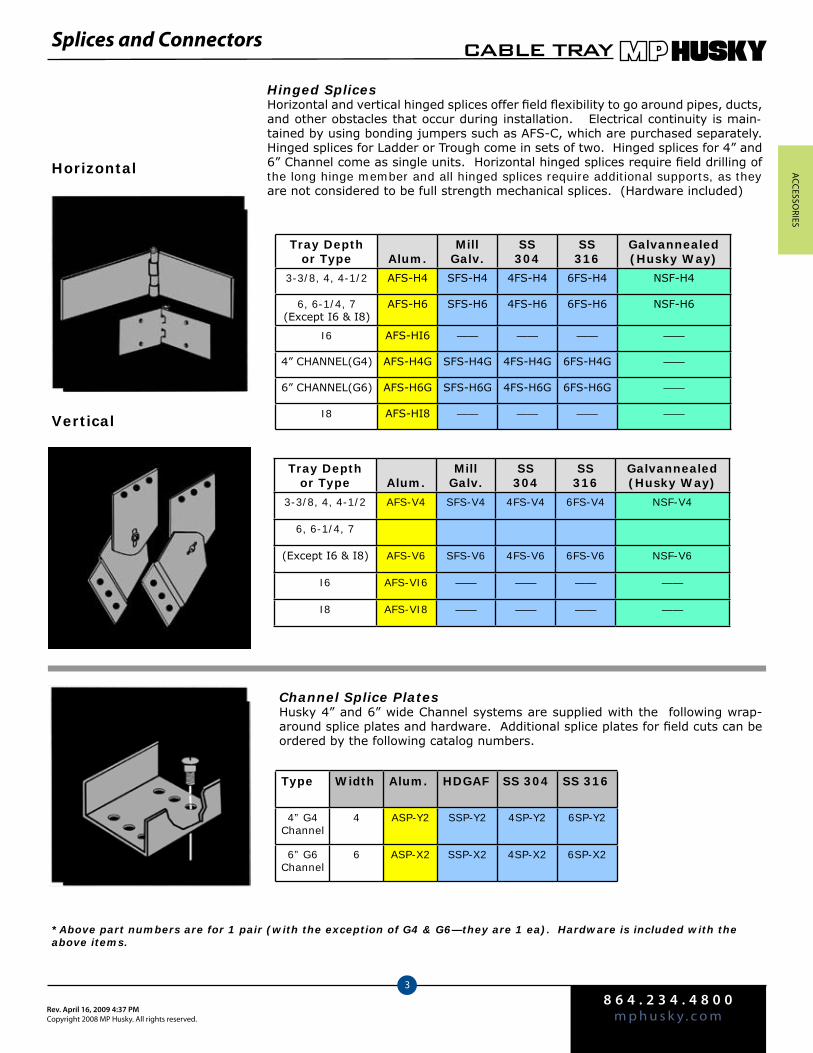
ACCeSSo
rieS
8 6 4 . 2 3 4 . 4 8 0 0m p h u s k y . c o mRev. April 16, 2009 4:37 PM
Copyright 2008 MP Husky. All rights reserved.
CABLE TRAY
3
Hinged Splices Horizontal and vertical hinged splices offer field flexibility to go around pipes, ducts, and other obstacles that occur during installation. Electrical continuity is main-tained by using bonding jumpers such as AFS-C, which are purchased separately. Hinged splices for Ladder or Trough come in sets of two. Hinged splices for 4” and 6” Channel come as single units. Horizontal hinged splices require field drilling of the long hinge member and all hinged splices require additional supports, as they are not considered to be full strength mechanical splices. (Hardware included)
Tray Depth or Type Alum.
MillGalv.
SS304
SS316
Galvannealed (Husky Way)
3-3/8, 4, 4-1/2 AFS-H4 SFS-H4 4FS-H4 6FS-H4 NSF-H4
6, 6-1/4, 7(Except I6 & I8)
AFS-H6 SFS-H6 4FS-H6 6FS-H6 NSF-H6
I6 AFS-HI6 —— —— —— ——
4” CHANNEL(G4) AFS-H4G SFS-H4G 4FS-H4G 6FS-H4G ——
6” CHANNEL(G6) AFS-H6G SFS-H6G 4FS-H6G 6FS-H6G ——
I8 AFS-HI8 —— —— —— ——
Tray Depth or Type Alum.
MillGalv.
SS304
SS316
Galvannealed (Husky Way)
3-3/8, 4, 4-1/2 AFS-V4 SFS-V4 4FS-V4 6FS-V4 NSF-V4
6, 6-1/4, 7
(Except I6 & I8) AFS-V6 SFS-V6 4FS-V6 6FS-V6 NSF-V6
I6 AFS-VI6 —— —— —— ——
I8 AFS-VI8 —— —— —— ——
Channel Splice PlatesHusky 4” and 6” wide Channel systems are supplied with the following wrap-around splice plates and hardware. Additional splice plates for field cuts can be ordered by the following catalog numbers.
Type Width Alum. HDGAF SS 304 SS 316
4” G4Channel
4 ASP-Y2 SSP-Y2 4SP-Y2 6SP-Y2
6” G6Channel
6 ASP-X2 SSP-X2 4SP-X2 6SP-X2
*Above part numbers are for 1 pair (with the exception of G4 & G6—they are 1 ea). Hardware is included with the above items.
Horizontal
Vertical
Splices and Connectors
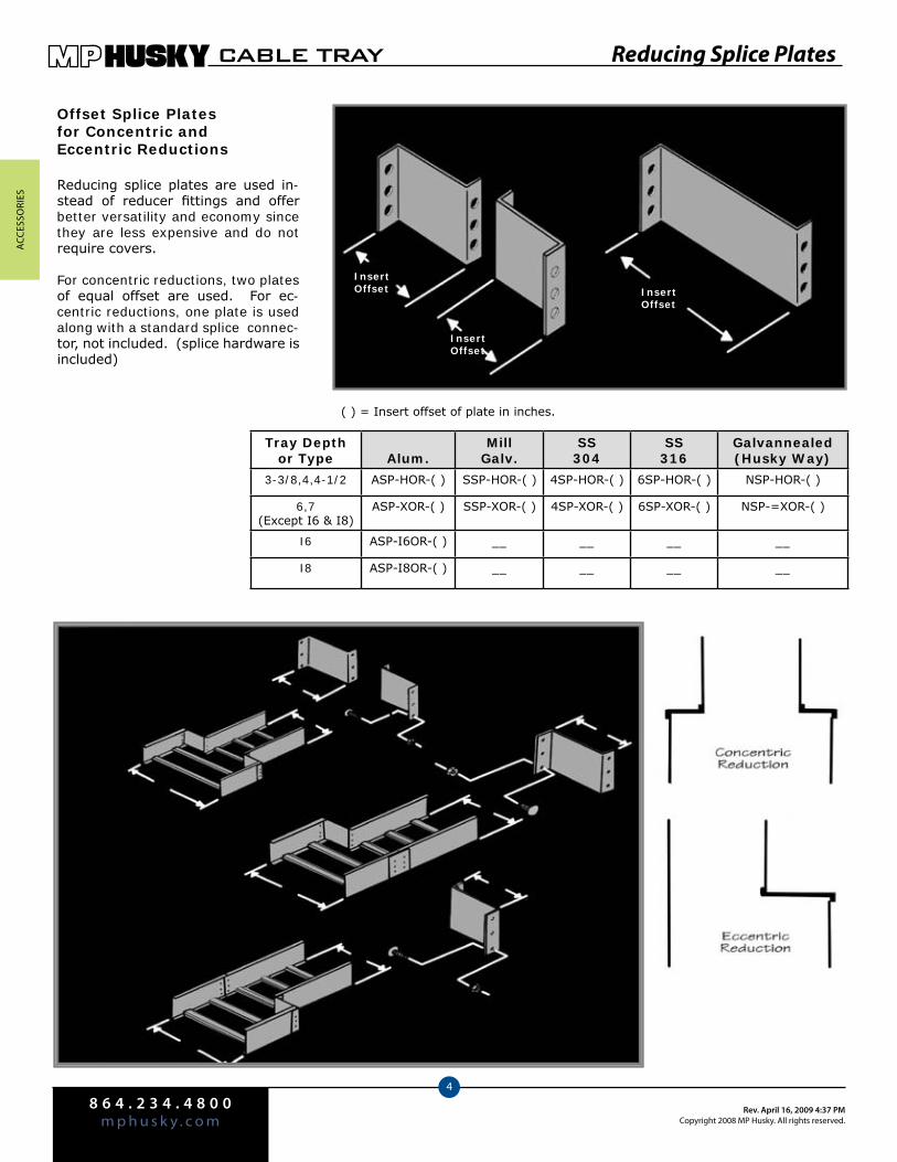
ACC
eSSo
rieS
8 6 4 . 2 3 4 . 4 8 0 0m p h u s k y . c o m
Rev. April 16, 2009 4:37 PMCopyright 2008 MP Husky. All rights reserved.
CABLE TRAY
4
Reducing Splice Plates
Tray Depth or Type Alum.
MillGalv.
SS304
SS316
Galvannealed (Husky Way)
3-3/8,4,4-1/2 ASP-HOR-( ) SSP-HOR-( ) 4SP-HOR-( ) 6SP-HOR-( ) NSP-HOR-( )
6,7(Except I6 & I8)
ASP-XOR-( ) SSP-XOR-( ) 4SP-XOR-( ) 6SP-XOR-( ) NSP-=XOR-( )
I6 ASP-I6OR-( ) __ __ __ __
I8 ASP-I8OR-( ) __ __ __ __
Offset Splice Plates for Concentric and Eccentric Reductions
Reducing splice plates are used in-stead of reducer fittings and offer better versatility and economy since they are less expensive and do not require covers.
For concentric reductions, two plates of equal offset are used. For ec-centric reductions, one plate is used along with a standard splice connec-tor, not included. (splice hardware is included)
( ) = Insert offset of plate in inches.
InsertOffset
InsertOffset
InsertOffset
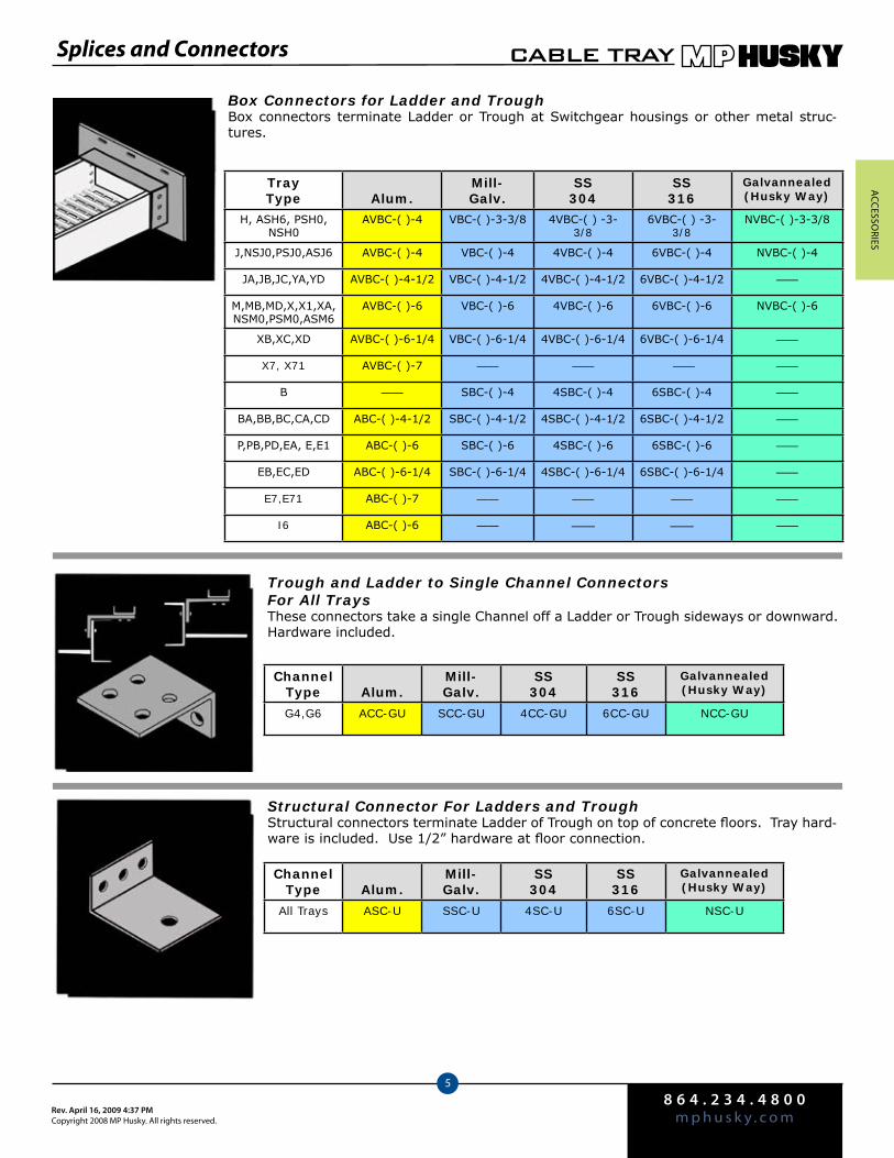
ACCeSSo
rieS
8 6 4 . 2 3 4 . 4 8 0 0m p h u s k y . c o mRev. April 16, 2009 4:37 PM
Copyright 2008 MP Husky. All rights reserved.
CABLE TRAY
5
Splices and Connectors
Box Connectors for Ladder and TroughBox connectors terminate Ladder or Trough at Switchgear housings or other metal struc-tures.
TrayType Alum.
Mill-Galv.
SS304
SS316
Galvannealed (Husky Way)
H, ASH6, PSH0, NSH0
AVBC-( )-4 VBC-( )-3-3/8 4VBC-( ) -3-3/8
6VBC-( ) -3-3/8
NVBC-( )-3-3/8
J,NSJ0,PSJ0,ASJ6 AVBC-( )-4 VBC-( )-4 4VBC-( )-4 6VBC-( )-4 NVBC-( )-4
JA,JB,JC,YA,YD AVBC-( )-4-1/2 VBC-( )-4-1/2 4VBC-( )-4-1/2 6VBC-( )-4-1/2 ——
M,MB,MD,X,X1,XA, NSM0,PSM0,ASM6
AVBC-( )-6 VBC-( )-6 4VBC-( )-6 6VBC-( )-6 NVBC-( )-6
XB,XC,XD AVBC-( )-6-1/4 VBC-( )-6-1/4 4VBC-( )-6-1/4 6VBC-( )-6-1/4 ——
X7, X71 AVBC-( )-7 —— —— —— ——
B —— SBC-( )-4 4SBC-( )-4 6SBC-( )-4 ——
BA,BB,BC,CA,CD ABC-( )-4-1/2 SBC-( )-4-1/2 4SBC-( )-4-1/2 6SBC-( )-4-1/2 ——
P,PB,PD,EA, E,E1 ABC-( )-6 SBC-( )-6 4SBC-( )-6 6SBC-( )-6 ——
EB,EC,ED ABC-( )-6-1/4 SBC-( )-6-1/4 4SBC-( )-6-1/4 6SBC-( )-6-1/4 ——
E7,E71 ABC-( )-7 —— —— —— ——
I6 ABC-( )-6 —— —— —— ——
Trough and Ladder to Single Channel Connectors For All TraysThese connectors take a single Channel off a Ladder or Trough sideways or downward. Hardware included.
ChannelType Alum.
Mill-Galv.
SS304
SS316
Galvannealed (Husky Way)
G4,G6 ACC-GU SCC-GU 4CC-GU 6CC-GU NCC-GU
Structural Connector For Ladders and TroughStructural connectors terminate Ladder of Trough on top of concrete floors. Tray hard-ware is included. Use 1/2” hardware at floor connection.
ChannelType Alum.
Mill-Galv.
SS304
SS316
Galvannealed (Husky Way)
All Trays ASC-U SSC-U 4SC-U 6SC-U NSC-U
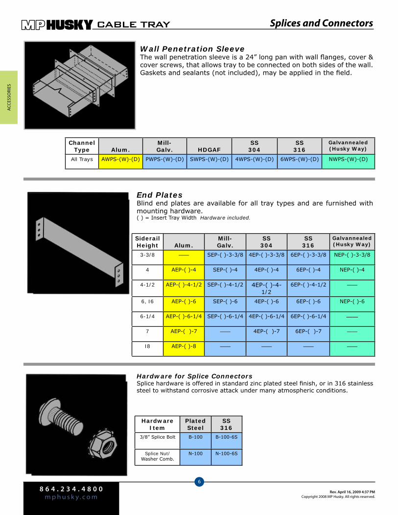
ACC
eSSo
rieS
8 6 4 . 2 3 4 . 4 8 0 0m p h u s k y . c o m
Rev. April 16, 2009 4:37 PMCopyright 2008 MP Husky. All rights reserved.
CABLE TRAY
6
Splices and Connectors
Wall Penetration SleeveThe wall penetration sleeve is a 24” long pan with wall flanges, cover & cover screws, that allows tray to be connected on both sides of the wall. Gaskets and sealants (not included), may be applied in the field.
End PlatesBlind end plates are available for all tray types and are furnished with mounting hardware.( ) = Insert Tray Width Hardware included.
Siderail Height Alum.
Mill-Galv.
SS304
SS316
Galvannealed (Husky Way)
3-3/8 —— SEP-( )-3-3/8 4EP-( )-3-3/8 6EP-( )-3-3/8 NEP-( )-3-3/8
4 AEP-( )-4 SEP-( )-4 4EP-( )-4 6EP-( )-4 NEP-( )-4
4-1/2 AEP-( )-4-1/2 SEP-( )-4-1/2 4EP-( )-4-1/2
6EP-( )-4-1/2 ——
6, I6 AEP-( )-6 SEP-( )-6 4EP-( )-6 6EP-( )-6 NEP-( )-6
6-1/4 AEP-( )-6-1/4 SEP-( )-6-1/4 4EP-( )-6-1/4 6EP-( )-6-1/4 ——
7 AEP-( )-7 —— 4EP-( )-7 6EP-( )-7 ——
I8 AEP-( )-8 —— —— —— ——
Hardware for Splice ConnectorsSplice hardware is offered in standard zinc plated steel finish, or in 316 stainless steel to withstand corrosive attack under many atmospheric conditions.
HardwareItem
Plated Steel
SS316
3/8” Splice Bolt B-100 B-100-6S
Splice Nut/Washer Comb.
N-100 N-100-6S
ChannelType Alum.
Mill-Galv. HDGAF
SS304
SS316
Galvannealed (Husky Way)
All Trays AWPS-(W)-(D) PWPS-(W)-(D) SWPS-(W)-(D) 4WPS-(W)-(D) 6WPS-(W)-(D) NWPS-(W)-(D)
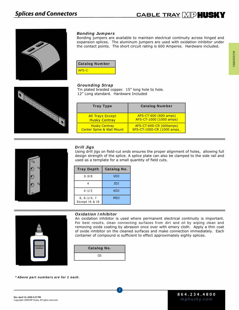
ACCeSSo
rieS
8 6 4 . 2 3 4 . 4 8 0 0m p h u s k y . c o mRev. April 16, 2009 4:37 PM
Copyright 2008 MP Husky. All rights reserved.
CABLE TRAY
7
Splices and Connectors
Bonding JumpersBonding jumpers are available to maintain electrical continuity across hinged and expansion splices. The aluminum jumpers are used with oxidation inhibitor under the contact points. The short circuit rating is 600 Amperes. Hardware included.
Catalog Number
AFS-C
Drill JigsUsing drill jigs on field-cut ends ensures the proper alignment of holes, allowing full design strength of the splice. A splice plate can also be clamped to the side rail and used as a template for a small quantity of field cuts.
Tray Depth Catalog No.
3-3/8 VDJ
4 JDJ
4-1/2 KDJ
6, 6-1/4, 7Except I6 & I8
MDJ
*Above part numbers are for 1 each.
Grounding StrapTin plated braided copper. 15” long hole to hole.12” Long standard. Hardware Included
Tray Type Catalog Number
All Trays ExceptHusky Centray
AFS-CT-600 (600 amps)AFS-CT-1000 (1000 amps)
Husky CentrayCenter Spine & Wall Mount
AFS-CT-600-CR (600amps)SFS-CT-1000-CR (1000 amps_
Oxidation InhibitorAn oxidation inhibitor is used where permanent electrical continuity is important. For best results, clean connecting surfaces from dirt and oil by wiping clean and removing oxide coating by abrasion once over with emery cloth. Apply a thin coat of oxide inhibitor on the cleaned surfaces and make connection immediately. Each container of compound is sufficient to effect approximately eighty splices.
Catalog No.
OI

ACC
eSSo
rieS
8 6 4 . 2 3 4 . 4 8 0 0m p h u s k y . c o m
Rev. April 16, 2009 4:37 PMCopyright 2008 MP Husky. All rights reserved.
CABLE TRAY
8
Accessories
End DropoutThis dropout is used at the end of a cable tray system, or to provide a smooth drop off for small cables at any point between the rungs in the ladder system. It is used in pairs, where dropping cable from both directions, or singly, when dropping cable in one direction. Hardware Included.
Hardware included. Part # is for 1 each.
TrayType Alum.
Mill-Galv.
SS304
SS316
Galvannealed (Husky Way)
H,J,JA,JB,JC,M,MB,MD,XB,XC,ASJ6,
NSHO,NSJO,NSMO
AVD-( ) SVD-( ) 4VD-( ) 6VD-( ) NVD-( )
XA,XD,YA,YD,X,X1,X7,X71,I6,I8,IYC,IMC,
IXB,IXC
AVD-( )-X SVD-( )-X 4VD-( )-X 6VD-( )-X NVD-( )-X
All Electray ABD-( ) SBD-( ) 4BD-( ) 6BD-( ) NBD-( )
Conduit Side Type DropoutsThe conduit side type dropout is a bracket used to secure a conduit clamp (not in-cluded), to the side rail of the tray, allowing cables to exit the tray into conduit drops to the equipment.
Part # is for 1 ea.
Tray Type Zinc Plated SS 304 SS 316
All Trays VDS-U 4VDS-U 6VDS-U
Mini TrimMini trim can be used as a protective edging to protect cables from sharp surfaces that cables may contact. Mini trim is a vinyl embossed extrusion with a segmented metal core that can be cut with a knife between the metal core segments. It will grip edges from .010” to .050” thick, and is supplied in 100 ft. rolls in black.
Catalog No.
MINI TRIM
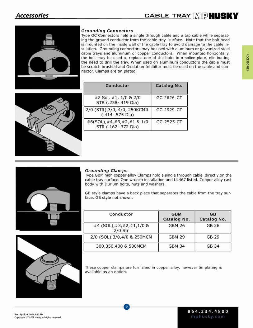
ACCeSSo
rieS
8 6 4 . 2 3 4 . 4 8 0 0m p h u s k y . c o mRev. April 16, 2009 4:37 PM
Copyright 2008 MP Husky. All rights reserved.
CABLE TRAY
9
Grounding ConnectorsType GC Connectors hold a single through cable and a tap cable while separat-ing the ground conductor from the cable tray surface. Note that the bolt head is mounted on the inside wall of the cable tray to avoid damage to the cable in-sulation. Grounding connectors may be used with aluminum or galvanized steel cable trays and aluminum or copper conductors. When mounted horizontally, the bolt may be used to replace one of the bolts in a splice plate, eliminating the need to drill the tray. When used on aluminum conductors the cable must be scratch brushed and Oxidation Inhibitor must be used on the cable and con-nector. Clamps are tin plated.
Conductor Catalog No.
#2 Sol, #1, 1/0 & 2/0 STR (.258-.419 Dia)
GC-2626-CT
2/0 (STR),3/0, 4/0, 250KCMIL(.414-.575 Dia)
GC-2929-CT
#6(SOL),#4,#3,#2,#1 & 1/0STR (.162-.372 Dia)
GC-2525-CT
Grounding ClampsType GBM high copper alloy Clamps hold a single through cable directly on the cable tray surface. One wrench installation and UL467 listed. Copper alloy cast body with Durium bolts, nuts and washers.
GB style clamps have a back piece that separates the cable from the tray sur-face. GB style not shown.
Conductor GBMCatalog No.
GBCatalog No.
#4 (SOL),#3,#2,#1,1/0 & 2/0 Str
GBM 26 GB 26
2/0 (SOL),3/0,4/0 & 250MCM GBM 29 GB 29
300,350,400 & 500MCM GBM 34 GB 34
These copper clamps are furnished in copper alloy, however tin plating is available as an option.
Accessories
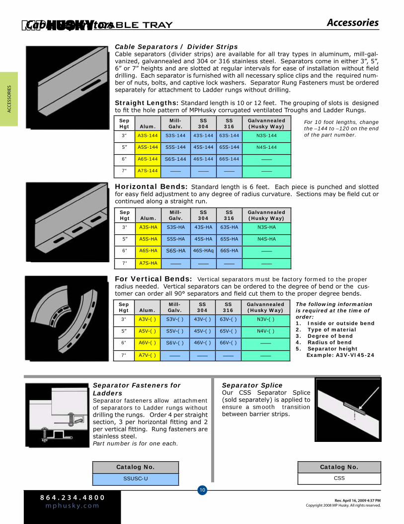
ACC
eSSo
rieS
8 6 4 . 2 3 4 . 4 8 0 0m p h u s k y . c o m
Rev. April 16, 2009 4:37 PMCopyright 2008 MP Husky. All rights reserved.
CABLE TRAY
10
Cable Separators
Cable Separators / Divider StripsCable separators (divider strips) are available for all tray types in aluminum, mill-gal-vanized, galvannealed and 304 or 316 stainless steel. Separators come in either 3”, 5”, 6” or 7” heights and are slotted at regular intervals for ease of installation without field drilling. Each separator is furnished with all necessary splice clips and the required num-ber of nuts, bolts, and captive lock washers. Separator Rung Fasteners must be ordered separately for attachment to Ladder rungs without drilling.
Horizontal Bends: Standard length is 6 feet. Each piece is punched and slotted for easy field adjustment to any degree of radius curvature. Sections may be field cut or continued along a straight run.
SepHgt Alum.
Mill- Galv.
SS 304
SS316
Galvannealed(Husky Way)
3” A3S-144 S3S-144 43S-144 63S-144 N3S-144
5” A5S-144 S5S-144 45S-144 65S-144 N4S-144
6” A6S-144 S6S-144 46S-144 66S-144 ——
7” A7S-144 —— —— —— ——
For Vertical Bends: Vertical separators must be factory formed to the proper radius needed. Vertical separators can be ordered to the degree of bend or the cus-tomer can order all 90° separators and field cut them to the proper degree bends.
Separator Fasteners for LaddersSeparator fasteners allow attachment of separators to Ladder rungs without drilling the rungs. Order 4 per straight section, 3 per horizontal fitting and 2 per vertical fitting. Rung fasteners are stainless steel. Part number is for one each.
Catalog No.
SSUSC-U
Catalog No.
CSS
Separator SpliceOur CSS Separator Splice (sold separately) is applied to ensure a smooth transition between barrier strips.
Straight Lengths: Standard length is 10 or 12 feet. The grouping of slots is designed to fit the hole pattern of MPHusky corrugated ventilated Troughs and Ladder Rungs.
For 10 foot lengths, change the –144 to –120 on the end of the part number.
Accessories
SepHgt Alum.
Mill- Galv.
SS 304
SS316
Galvannealed(Husky Way)
3” A3S-HA S3S-HA 43S-HA 63S-HA N3S-HA
5” A5S-HA S5S-HA 45S-HA 65S-HA N4S-HA
6” A6S-HA S6S-HA 46S-HAq 66S-HA ——
7” A7S-HA —— —— —— ——
The following information is required at the time of order:
Inside or outside bend1. Type of material2. Degree of bend3. Radius of bend4. Separator height5.
Example: A3V-VI45-24
SepHgt Alum.
Mill- Galv.
SS 304
SS316
Galvannealed(Husky Way)
3” A3V-( ) S3V-( ) 43V-( ) 63V-( ) N3V-( )
5” A5V-( ) S5V-( ) 45V-( ) 65V-( ) N4V-( )
6” A6V-( ) S6V-( ) 46V-( ) 66V-( ) ——
7” A7V-( ) —— —— —— ——

11.1
For more information or to order, call 1-800-277-4810 or visit www.mphusky.com.
SupportMaterial
Hold Down Clamps & Expansion Guide Pgs. 12.2-12.4 Tray Hanger clips Pg. 12.5 Suspension Channels and Fittings Pgs. 12.6-12.7Beam Clamps Pg. 12.8Hangers Pg. 12.9 Supports Pgs. 12.10-12.11 Brackets Pgs. 12.12-12.14
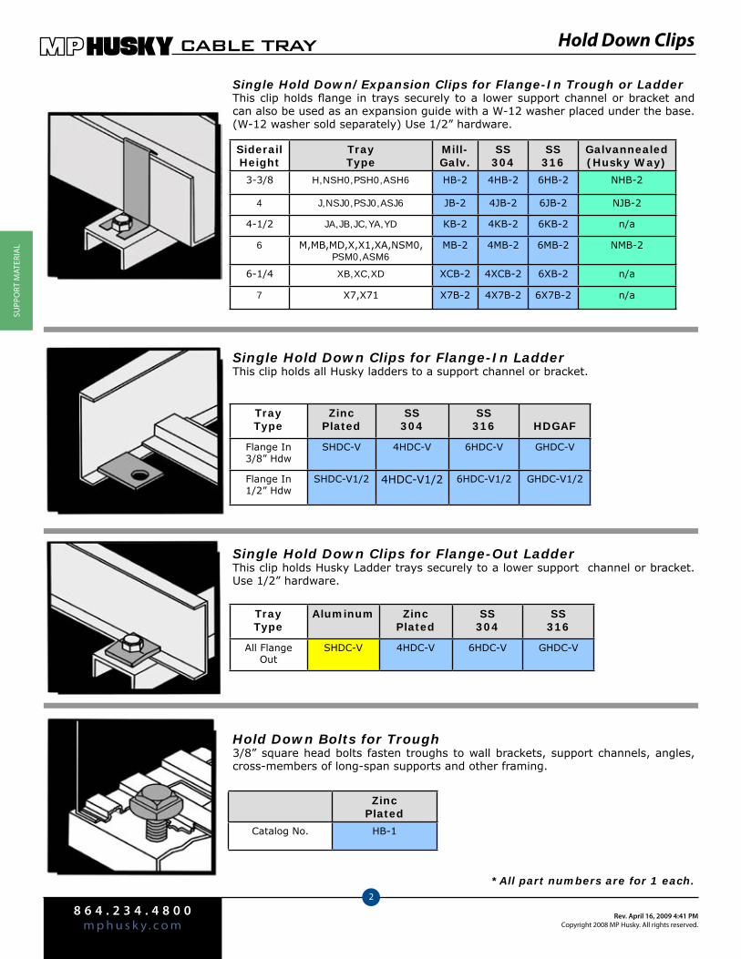
8 6 4 . 2 3 4 . 4 8 0 0m p h u s k y . c o m
Rev. April 16, 2009 4:41 PMCopyright 2008 MP Husky. All rights reserved.
CABLE TRAY
2
SuPP
orT
MAT
EriA
l
Hold Down Clips
Single Hold Down/Expansion Clips for Flange-In Trough or LadderThis clip holds flange in trays securely to a lower support channel or bracket and can also be used as an expansion guide with a W-12 washer placed under the base. (W-12 washer sold separately) Use 1/2” hardware.
SiderailHeight
TrayType
Mill-Galv.
SS304
SS316
Galvannealed(Husky Way)
3-3/8 H,NSH0,PSH0,ASH6 HB-2 4HB-2 6HB-2 NHB-2
4 J,NSJ0,PSJ0,ASJ6 JB-2 4JB-2 6JB-2 NJB-2
4-1/2 JA,JB,JC,YA,YD KB-2 4KB-2 6KB-2 n/a
6 M,MB,MD,X,X1,XA,NSM0, PSM0,ASM6
MB-2 4MB-2 6MB-2 NMB-2
6-1/4 XB,XC,XD XCB-2 4XCB-2 6XB-2 n/a
7 X7,X71 X7B-2 4X7B-2 6X7B-2 n/a
Single Hold Down Clips for Flange-In LadderThis clip holds all Husky ladders to a support channel or bracket.
TrayType
ZincPlated
SS304
SS316 HDGAF
Flange In3/8” Hdw
SHDC-V 4HDC-V 6HDC-V GHDC-V
Flange In1/2” Hdw
SHDC-V1/2 4HDC-V1/2 6HDC-V1/2 GHDC-V1/2
*All part numbers are for 1 each.
Hold Down Bolts for Trough3/8” square head bolts fasten troughs to wall brackets, support channels, angles, cross-members of long-span supports and other framing.
ZincPlated
Catalog No. HB-1
Single Hold Down Clips for Flange-Out LadderThis clip holds Husky Ladder trays securely to a lower support channel or bracket. Use 1/2” hardware.
TrayType
Aluminum ZincPlated
SS304
SS316
All Flange Out
SHDC-V 4HDC-V 6HDC-V GHDC-V

8 6 4 . 2 3 4 . 4 8 0 0m p h u s k y . c o mRev. April 16, 2009 4:41 PM
Copyright 2008 MP Husky. All rights reserved.
CABLE TRAY
3
SuPPo
rT MATEriA
l
Hold Down Clips
Double Hold Down Clips for Ladder and TroughDouble hold down clips allow two side by side trays to be fastened to the support with one clip and less hardware. Use 1/2” hardware.
Hold Down Bolts for ChannelSpecial 3/8” bolts are used to fasten 4” & 6” wide Husky channels to channel hangers and other supports.
TrayType Alum.
ZincPlated
SS304
SS316
3/4 AHDC-2A SHDC-2A 4HDC-2A 6HDC-2A
1-1/2 AHDC-2CA SHDC-2CA 4HDC-2CA 6HDC-2CA
1-3/4 AHDC-2C SHDC-2C 4HDC-2C 6HDC-2C
ZincPlated
Catalog No. HB-10
Guides for LadderExpansion guides are used to secure ladder style trays, while guiding the tray during movement during thermal expansion. For expansion guide recommendations, contact your local represen-tative or the factory. Use 1/2” hardware.
TrayType Alum.
ZincPlated
SS304
Ss316
All Flange In Husky Tray
AEXG-VL SEXG-VL 4EXG-VL 6EXG-VL
All Flange Out Husky Tray
AEXG-EL SEXG-EL 4EXG-EL 6EXG-EL
Hold Down/Expansion Guide for Flange Out LadderThese special heavy duty tray hold down clamps and expansion guides are ideal for fastening tray to C-Channels, such as those found on bridges. They are easy to install and reduce field labor costs since the beam clamp set screw eliminates the need to drill the C-Channel.
All Flange Out Ladders Zinc Plated
Hold Down Clamp HP-514A-PW
Expansion Guide HP-514A-PWO
*All part numbers are for 1 each.
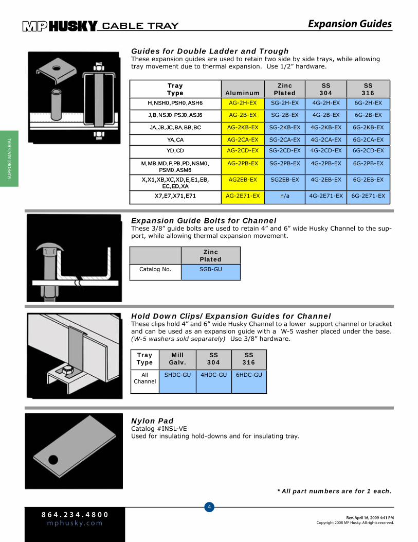
8 6 4 . 2 3 4 . 4 8 0 0m p h u s k y . c o m
Rev. April 16, 2009 4:41 PMCopyright 2008 MP Husky. All rights reserved.
CABLE TRAY
4
SuPP
orT
MAT
EriA
l
Expansion Guides
Guides for Double Ladder and TroughThese expansion guides are used to retain two side by side trays, while allowing tray movement due to thermal expansion. Use 1/2” hardware.
TrayType Aluminum
ZincPlated
SS304
SS316
H,NSH0,PSH0,ASH6 AG-2H-EX SG-2H-EX 4G-2H-EX 6G-2H-EX
J,B,NSJ0,PSJ0,ASJ6 AG-2B-EX SG-2B-EX 4G-2B-EX 6G-2B-EX
JA,JB,JC,BA,BB,BC AG-2KB-EX SG-2KB-EX 4G-2KB-EX 6G-2KB-EX
YA,CA AG-2CA-EX SG-2CA-EX 4G-2CA-EX 6G-2CA-EX
YD,CD AG-2CD-EX SG-2CD-EX 4G-2CD-EX 6G-2CD-EX
M,MB,MD,P,PB,PD,NSM0, PSM0,ASM6
AG-2PB-EX SG-2PB-EX 4G-2PB-EX 6G-2PB-EX
X,X1,XB,XC,XD,E,E1,EB, EC,ED,XA
AG2EB-EX SG2EB-EX 4G-2EB-EX 6G-2EB-EX
X7,E7,X71,E71 AG-2E71-EX n/a 4G-2E71-EX 6G-2E71-EX
Hold Down Clips/Expansion Guides for ChannelThese clips hold 4” and 6” wide Husky Channel to a lower support channel or bracket and can be used as an expansion guide with a W-5 washer placed under the base. (W-5 washers sold separately) Use 3/8” hardware.
TrayType
MillGalv.
SS304
SS316
All Channel
SHDC-GU 4HDC-GU 6HDC-GU
Expansion Guide Bolts for ChannelThese 3/8” guide bolts are used to retain 4” and 6” wide Husky Channel to the sup-port, while allowing thermal expansion movement.
ZincPlated
Catalog No. SGB-GU
*All part numbers are for 1 each.
Nylon PadCatalog #INSL-VEUsed for insulating hold-downs and for insulating tray.
TrayType Aluminum
ZincPlated
SS304
SS316
H,NSH0,PSH0,ASH6 AG-2H-EX SG-2H-EX 4G-2H-EX 6G-2H-EX
J,B,NSJ0,PSJ0,ASJ6 AG-2B-EX SG-2B-EX 4G-2B-EX 6G-2B-EX
JA,JB,JC,BA,BB,BC AG-2KB-EX SG-2KB-EX 4G-2KB-EX 6G-2KB-EX
YA,CA AG-2CA-EX SG-2CA-EX 4G-2CA-EX 6G-2CA-EX
YD,CD AG-2CD-EX SG-2CD-EX 4G-2CD-EX 6G-2CD-EX
M,MB,MD,P,PB,PD,NSM0, PSM0,ASM6
AG-2PB-EX SG-2PB-EX 4G-2PB-EX 6G-2PB-EX
X,X1,XB,XC,XD,E,E1,EB, EC,ED,XA
AG2EB-EX SG2EB-EX 4G-2EB-EX 6G-2EB-EX
X7,E7,X71,E71 AG-2E71-EX n/a 4G-2E71-EX 6G-2E71-EX
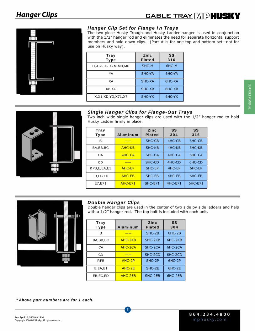
8 6 4 . 2 3 4 . 4 8 0 0m p h u s k y . c o mRev. April 16, 2009 4:41 PM
Copyright 2008 MP Husky. All rights reserved.
CABLE TRAY
5
SuPPo
rT MATEriA
l
Hanger Clips
Hanger Clip Set for Flange In TraysThe two-piece Husky Trough and Husky Ladder hanger is used in conjunction with the 1/2” hanger rod and eliminates the need for separate horizontal support members and hold down clips. (Part # is for one top and bottom set—not for use on Husky way).
TrayType
ZincPlated
SS316
H,J,JA,JB,JC,M,MB,MD SHC-M 6HC-M
YA SHC-YA 6HC-YA
XA SHC-XA 6HC-XA
XB,XC SHC-XB 6HC-XB
X,X1,XD,YD,X71,X7 SHC-YX 6HC-YX
Single Hanger Clips for Flange-Out TraysTwo inch wide single hanger clips are used with the 1/2” hanger rod to hold Husky Ladder firmly in place.
Double Hanger ClipsDouble hanger clips are used in the center of two side by side ladders and help with a 1/2” hanger rod. The top bolt is included with each unit.
*Above part numbers are for 1 each.
TrayType Aluminum
ZincPlated
SS304
SS316
B —— SHC-CB 4HC-CB 6HC-CB
BA,BB,BC AHC-KB SHC-KB 4HC-KB 6HC-KB
CA AHC-CA SHC-CA 4HC-CA 6HC-CA
CD —— SHC-CD 4HC-CD 6HC-CD
P,PB,E,EA,E1 AHC-EP SHC-EP 4HC-EP 6HC-EP
EB,EC,ED AHC-EB SHC-EB 4HC-EB 6HC-EB
E7,E71 AHC-E71 SHC-E71 4HC-E71 6HC-E71
TrayType Aluminum
ZincPlated
SS304
B —— SHC-2B 6HC-2B
BA,BB,BC AHC-2KB SHC-2KB 6HC-2KB
CA AHC-2CA SHC-2CA 6HC-2CA
CD —— SHC-2CD 6HC-2CD
P,PB AHC-2P SHC-2P 6HC-2P
E,EA,E1 AHC-2E SHC-2E 6HC-2E
EB,EC,ED AHC-2EB SHC-2EB 6HC-2EB
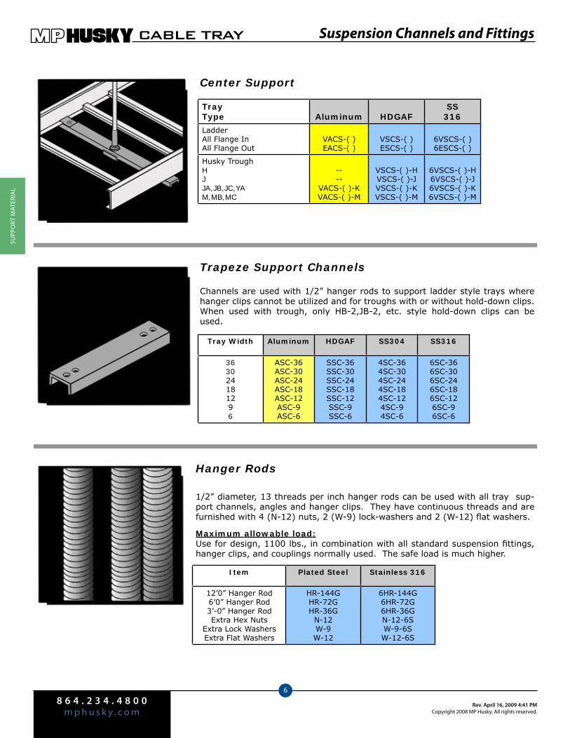
8 6 4 . 2 3 4 . 4 8 0 0m p h u s k y . c o m
Rev. April 16, 2009 4:41 PMCopyright 2008 MP Husky. All rights reserved.
CABLE TRAY
6
SuPP
orT
MAT
EriA
l
Suspension Channels and Fittings
Channels are used with 1/2” hanger rods to support ladder style trays where hanger clips cannot be utilized and for troughs with or without hold-down clips. When used with trough, only HB-2,JB-2, etc. style hold-down clips can be used.
Center Support
Hanger Rods
Trapeze Support Channels
Item Plated Steel Stainless 316
12’0” Hanger Rod6’0” Hanger Rod3’-0” Hanger RodExtra Hex Nuts
Extra Lock WashersExtra Flat Washers
HR-144GHR-72GHR-36G
N-12W-9W-12
6HR-144G6HR-72G6HR-36GN-12-6SW-9-6SW-12-6S
Tray Width Aluminum HDGAF SS304 SS316
363024181296
ASC-36ASC-30ASC-24ASC-18ASC-12ASC-9ASC-6
SSC-36SSC-30SSC-24SSC-18SSC-12SSC-9SSC-6
4SC-364SC-304SC-244SC-184SC-124SC-94SC-6
6SC-366SC-306SC-246SC-186SC-126SC-96SC-6
1/2” diameter, 13 threads per inch hanger rods can be used with all tray sup-port channels, angles and hanger clips. They have continuous threads and are furnished with 4 (N-12) nuts, 2 (W-9) lock-washers and 2 (W-12) flat washers.
Maximum allowable load:Use for design, 1100 lbs., in combination with all standard suspension fittings, hanger clips, and couplings normally used. The safe load is much higher.
TrayType Aluminum HDGAF
SS316
LadderAll Flange InAll Flange Out
VACS-( )EACS-( )
VSCS-( )ESCS-( )
6VSCS-( )6ESCS-( )
Husky TroughHJJA,JB,JC,YAM,MB,MC
----
VACS-( )-KVACS-( )-M
VSCS-( )-HVSCS-( )-JVSCS-( )-KVSCS-( )-M
6VSCS-( )-H6VSCS-( )-J6VSCS-( )-K6VSCS-( )-M
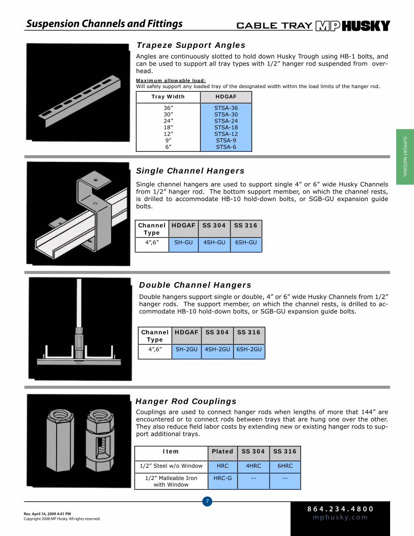
8 6 4 . 2 3 4 . 4 8 0 0m p h u s k y . c o mRev. April 16, 2009 4:41 PM
Copyright 2008 MP Husky. All rights reserved.
CABLE TRAY
7
SuPPo
rT MATEriA
l
Suspension Channels and Fittings
Angles are continuously slotted to hold down Husky Trough using HB-1 bolts, and can be used to support all tray types with 1/2” hanger rod suspended from over-head.Maximum allowable load:Will safely support any loaded tray of the designated width within the load limits of the hanger rod.
Single channel hangers are used to support single 4” or 6” wide Husky Channels from 1/2” hanger rod. The bottom support member, on which the channel rests, is drilled to accommodate HB-10 hold-down bolts, or SGB-GU expansion guide bolts.
Double hangers support single or double, 4” or 6” wide Husky Channels from 1/2” hanger rods. The support member, on which the channel rests, is drilled to ac-commodate HB-10 hold-down bolts, or SGB-GU expansion guide bolts.
Trapeze Support Angles
Single Channel Hangers
Double Channel Hangers
Tray Width HDGAF
36”30”24”18”12”9”6”
STSA-36STSA-30STSA-24STSA-18STSA-12STSA-9STSA-6
Channel Type
HDGAF SS 304 SS 316
4”,6” SH-GU 4SH-GU 6SH-GU
Hanger Rod CouplingsCouplings are used to connect hanger rods when lengths of more that 144” are encountered or to connect rods between trays that are hung one over the other. They also reduce field labor costs by extending new or existing hanger rods to sup-port additional trays.
Channel Type
HDGAF SS 304 SS 316
4”,6” SH-2GU 4SH-2GU 6SH-2GU
Item Plated SS 304 SS 316
1/2” Steel w/o Window HRC 4HRC 6HRC
1/2” Malleable Ironwith Window
HRC-G -- --
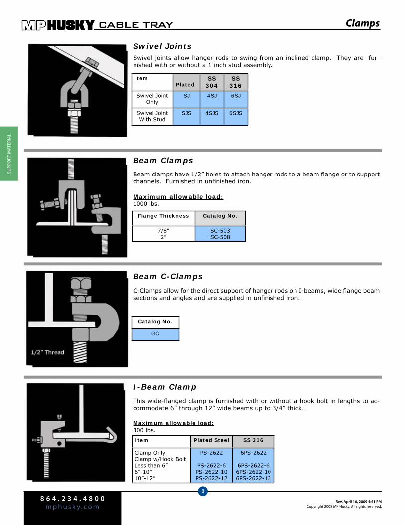
8 6 4 . 2 3 4 . 4 8 0 0m p h u s k y . c o m
Rev. April 16, 2009 4:41 PMCopyright 2008 MP Husky. All rights reserved.
CABLE TRAY
8
SuPP
orT
MAT
EriA
l
Clamps
Swivel JointsSwivel joints allow hanger rods to swing from an inclined clamp. They are fur-nished with or without a 1 inch stud assembly.
ItemPlated
SS 304
SS 316
Swivel Joint Only
SJ 4SJ 6SJ
Swivel JointWith Stud
SJS 4SJS 6SJS
This wide-flanged clamp is furnished with or without a hook bolt in lengths to ac-commodate 6” through 12” wide beams up to 3/4” thick.
Maximum allowable load:300 lbs.
I-Beam Clamp
Item Plated Steel SS 316
Clamp OnlyClamp w/Hook BoltLess than 6”6”-10”10”-12”
PS-2622
PS-2622-6PS-2622-10PS-2622-12
6PS-2622
6PS-2622-66PS-2622-106PS-2622-12
Beam clamps have 1/2” holes to attach hanger rods to a beam flange or to support channels. Furnished in unfinished iron.
Maximum allowable load:1000 lbs.
Beam Clamps
Flange Thickness Catalog No.
7/8”2”
SC-503SC-508
C-Clamps allow for the direct support of hanger rods on I-beams, wide flange beam sections and angles and are supplied in unfinished iron.
Beam C-Clamps
Catalog No.
GC

8 6 4 . 2 3 4 . 4 8 0 0m p h u s k y . c o mRev. April 16, 2009 4:41 PM
Copyright 2008 MP Husky. All rights reserved.
CABLE TRAY
9
SuPPo
rT MATEriA
l
Hangers
The standard size is 1-1/4” square with a 1/2” bevel and a 9/16” hole. Bolt and nut not included.
Bevel Washers
Catalog No.
W-11
Vertical Hangers For Tray
Vertical Hangers For Channel
Vertical hangers support single-type vertical ladders or troughs from 1/2” hanger rods. Each is furnished with the required mounting hardware.
Maximum allowable load:250 lbs. per unit
HDGAF SH-VU
SS 316 6SH-VU
This hanger assembly for vertical channels accom-modates either 4” or 6” wide channels and is fur-nished with all necessary hardware, except for the top 1/2” hanger rod to the building steel.
Maximum allowable load:200 lbs.
HDGAF SH-VGU
SS 316 6SH-VGU
Channel Clamps
Channel clamp assemblies can be used on all American Standard channels with a flange width of 3-1/4” or less. They are furnished in zinc plated steel with or without a swivel joint.
Maximum allowable load:500 lbs. with a safety factor of 5
Item Zinc Plated Steel
Clamp Only HP-177
Clamp w/Swivel JointHP-177SJ
HP Channel Clamps
HP single and back to back strut type support channels are attached to structural beams with a 0.8” maximum flange thickness. Clamps are furnished with the re-quired hardware.
Maximum allowable load:1,275 lbs. with a safety factor of 5
Channel Type Zinc Plated Steel
HP-200 Single Strut HP-265A
HP-201 Double Strut HP-265D
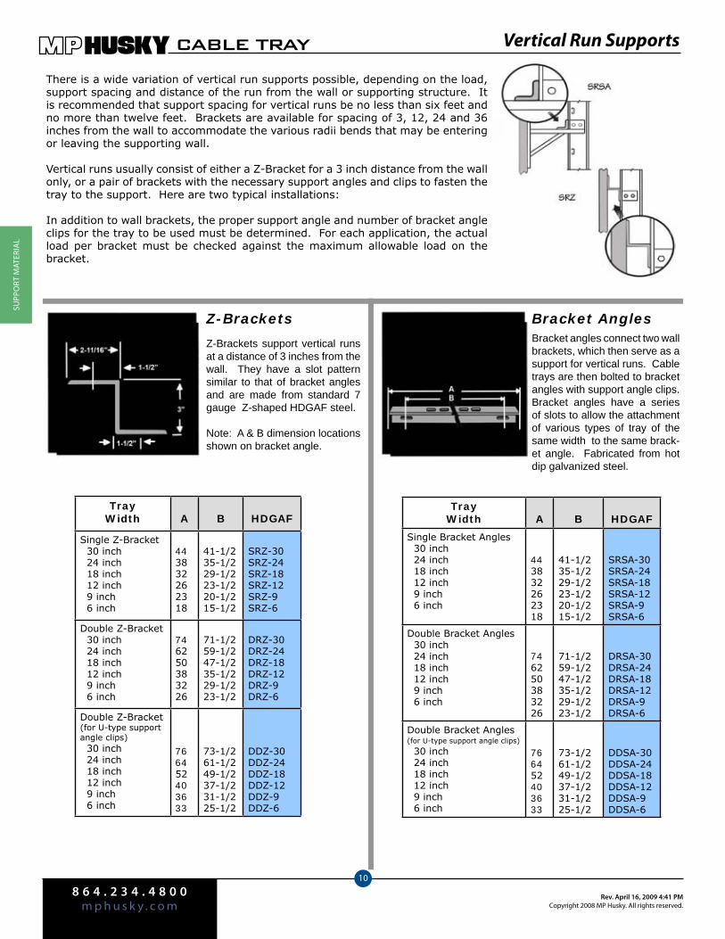
8 6 4 . 2 3 4 . 4 8 0 0m p h u s k y . c o m
Rev. April 16, 2009 4:41 PMCopyright 2008 MP Husky. All rights reserved.
CABLE TRAY
10
SuPP
orT
MAT
EriA
l
Vertical Run Supports
There is a wide variation of vertical run supports possible, depending on the load, support spacing and distance of the run from the wall or supporting structure. It is recommended that support spacing for vertical runs be no less than six feet and no more than twelve feet. Brackets are available for spacing of 3, 12, 24 and 36 inches from the wall to accommodate the various radii bends that may be entering or leaving the supporting wall.
Vertical runs usually consist of either a Z-Bracket for a 3 inch distance from the wall only, or a pair of brackets with the necessary support angles and clips to fasten the tray to the support. Here are two typical installations:
In addition to wall brackets, the proper support angle and number of bracket angle clips for the tray to be used must be determined. For each application, the actual load per bracket must be checked against the maximum allowable load on the bracket.
Bracket AnglesZ-BracketsBracket angles connect two wall brackets, which then serve as a support for vertical runs. Cable trays are then bolted to bracket angles with support angle clips. Bracket angles have a series of slots to allow the attachment of various types of tray of the same width to the same brack-et angle. Fabricated from hot dip galvanized steel.
Z-Brackets support vertical runs at a distance of 3 inches from the wall. They have a slot pattern similar to that of bracket angles and are made from standard 7 gauge Z-shaped HDGAF steel.
Note: A & B dimension locations shown on bracket angle.
TrayWidth A B HDGAF
Single Bracket Angles 30 inch 24 inch 18 inch 12 inch 9 inch 6 inch
443832262318
41-1/235-1/229-1/223-1/220-1/215-1/2
SRSA-30SRSA-24SRSA-18SRSA-12SRSA-9SRSA-6
Double Bracket Angles 30 inch 24 inch 18 inch 12 inch 9 inch 6 inch
746250383226
71-1/259-1/247-1/235-1/229-1/223-1/2
DRSA-30DRSA-24DRSA-18DRSA-12DRSA-9DRSA-6
Double Bracket Angles(for U-type support angle clips)
30 inch 24 inch 18 inch 12 inch 9 inch 6 inch
766452403633
73-1/261-1/249-1/237-1/231-1/225-1/2
DDSA-30DDSA-24DDSA-18DDSA-12DDSA-9DDSA-6
TrayWidth A B HDGAF
Single Z-Bracket 30 inch 24 inch 18 inch 12 inch 9 inch 6 inch
443832262318
41-1/235-1/229-1/223-1/220-1/215-1/2
SRZ-30SRZ-24SRZ-18SRZ-12SRZ-9SRZ-6
Double Z-Bracket 30 inch 24 inch 18 inch 12 inch 9 inch 6 inch
746250383226
71-1/259-1/247-1/235-1/229-1/223-1/2
DRZ-30DRZ-24DRZ-18DRZ-12DRZ-9DRZ-6
Double Z-Bracket (for U-type support angle clips) 30 inch 24 inch 18 inch 12 inch 9 inch 6 inch
766452403633
73-1/261-1/249-1/237-1/231-1/225-1/2
DDZ-30DDZ-24DDZ-18DDZ-12DDZ-9DDZ-6
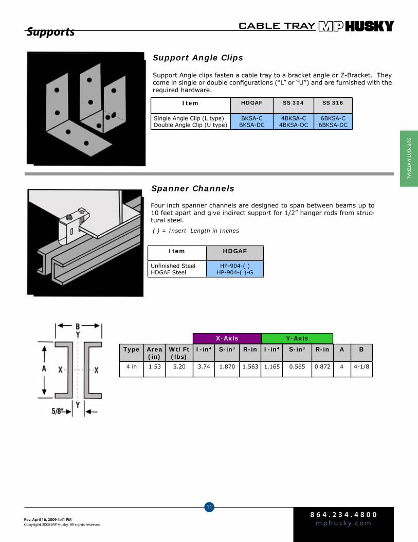
8 6 4 . 2 3 4 . 4 8 0 0m p h u s k y . c o mRev. April 16, 2009 4:41 PM
Copyright 2008 MP Husky. All rights reserved.
CABLE TRAY
11
SuPPo
rT MATEriA
l
Supports
Support Angle Clips
Support Angle clips fasten a cable tray to a bracket angle or Z-Bracket. They come in single or double configurations (“L” or “U”) and are furnished with the required hardware.
Item HDGAF SS 304 SS 316
Single Angle Clip (L type)Double Angle Clip (U type)
BKSA-CBKSA-DC
4BKSA-C4BKSA-DC
6BKSA-C6BKSA-DC
Spanner Channels
Four inch spanner channels are designed to span between beams up to 10 feet apart and give indirect support for 1/2” hanger rods from struc-tural steel.
( ) = Insert Length in Inches
Item HDGAF
Unfinished SteelHDGAF Steel
HP-904-( )HP-904-( )-G
X-Axis Y-Axis
Type Area(in)
Wt/Ft(lbs)
I-in4 S-in3 R-in I-in4 S-in3 R-in A B
4 in 1.53 5.20 3.74 1.870 1.563 1.165 0.565 0.872 4 4-1/8

8 6 4 . 2 3 4 . 4 8 0 0m p h u s k y . c o m
Rev. April 16, 2009 4:41 PMCopyright 2008 MP Husky. All rights reserved.
CABLE TRAY
12
SuPP
orT
MAT
EriA
l
Wall Brackets
MPHusky offers a variety of wall brackets to support trays and channels from any wall or vertical support. The design of the brackets takes into consideration whether the trays or channels will be supported singly or two in parallel, on hori-zontal or vertical runs, the distance from the wall, bend radii, etc.
The allowable load of each type of bracket is given below: Condition 1—Where the load is applied at two points (ladders or troughs apart in width). Condition 2—Where the load is applied as a single concentrated load at the end of the bracket (as when supporting vertical runs).
A minimum safety factor of 2 against yield has been used in determining the maximum allowable load. All calculations have been confirmed by testing. Brackets are most commonly used for single or double horizontal runs.
Channel Brackets
Channel brackets will accommodate single or double channel runs with pre-drilled holes for HB-10 Hold Down Bolts or SGB-GU expansion guides, purchased sepa-rately.
Maximum allowable load:Twice the allowable load for the respective channel at a support spacing of 10 feet.
Item HDGAF SS 304 SS 316
Single for 4” ChannelDouble for 4” ChannelSingle for 6” ChannelDouble for 6” Channel
SSBK-GSDBK-GSSBK-G6SDBK-G6
4SSBK-G4SDBK-G4SSBK-G64SDBK-G6
6SSBK-G6SDBK-G6SSBK-G66SDBK-G6
Low Headroom Brackets
Low headroom brackets are designed to attach Husky Trough and Husky Flange In Ladder to wall mounted strut type channel framing. Available in HDGAF.
Maximum allowable load:Condition 1—500 lbs.Condition 2—250 lbs.
A B C HDGAF
251913107
2115963
11-3/42-1/2
2-13/163-3/16
VBK-24VBK-18VBK-12VBK-9VBK-6
Condition 1
Condition 2
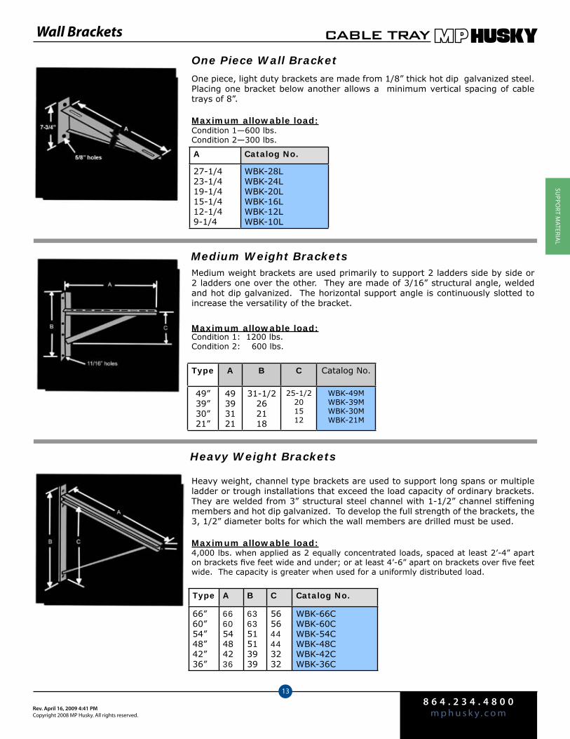
8 6 4 . 2 3 4 . 4 8 0 0m p h u s k y . c o mRev. April 16, 2009 4:41 PM
Copyright 2008 MP Husky. All rights reserved.
CABLE TRAY
13
SuPPo
rT MATEriA
l
Wall Brackets
Medium Weight BracketsMedium weight brackets are used primarily to support 2 ladders side by side or 2 ladders one over the other. They are made of 3/16” structural angle, welded and hot dip galvanized. The horizontal support angle is continuously slotted to increase the versatility of the bracket.
Maximum allowable load:Condition 1: 1200 lbs.Condition 2: 600 lbs.
Heavy Weight Brackets
Heavy weight, channel type brackets are used to support long spans or multiple ladder or trough installations that exceed the load capacity of ordinary brackets. They are welded from 3” structural steel channel with 1-1/2” channel stiffening members and hot dip galvanized. To develop the full strength of the brackets, the 3, 1/2” diameter bolts for which the wall members are drilled must be used.
Maximum allowable load:4,000 lbs. when applied as 2 equally concentrated loads, spaced at least 2’-4” apart on brackets five feet wide and under; or at least 4’-6” apart on brackets over five feet wide. The capacity is greater when used for a uniformly distributed load.
One Piece Wall Bracket
One piece, light duty brackets are made from 1/8” thick hot dip galvanized steel. Placing one bracket below another allows a minimum vertical spacing of cable trays of 8”.
Maximum allowable load:Condition 1—600 lbs.Condition 2—300 lbs.
A Catalog No.
27-1/423-1/419-1/415-1/412-1/49-1/4
WBK-28LWBK-24LWBK-20LWBK-16LWBK-12LWBK-10L
Type A B C Catalog No.
49”39”30”21”
49393121
31-1/2262118
25-1/2201512
WBK-49MWBK-39MWBK-30MWBK-21M
Type A B C Catalog No.
66”60”54”48”42”36”
666054484236
636351513939
565644443232
WBK-66CWBK-60CWBK-54CWBK-48CWBK-42CWBK-36C
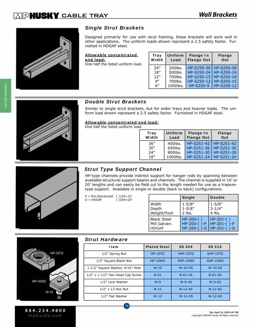
8 6 4 . 2 3 4 . 4 8 0 0m p h u s k y . c o m
Rev. April 16, 2009 4:41 PMCopyright 2008 MP Husky. All rights reserved.
CABLE TRAY
14
SuPP
orT
MAT
EriA
l
Wall Brackets
Single Strut Brackets
Designed primarily for use with strut framing, these brackets will work well in other applications. The uniform loads shown represent a 2.5 safety factor. Fur-nished in HDGAF steel.
Allowable concentrated end load:One half the listed uniform load.
TrayWidth
UniformLoad
Flange InFlange Out
FlangeOut
24”18”12”9”6”
200lbs.500lbs.700lbs.700lbs.1000lbs.
HP-S250-30HP-S250-24HP-S250-15HP-S250-12HP-S250-9
HP-S250-30HP-S250-24HP-S250-18HP-S250-15HP-S250-12
Double Strut BracketsSimilar to single strut brackets, but for wider trays and heavier loads. The uni-form load shown represent a 2.5 safety factor. Furnished in HDGAF steel.
Allowable concentrated end load:One half the listed uniform load.
TrayWidth
UniformLoad
Flange InFlange Out
FlangeOut
36”30”24”18”
400lbs.650lbs.800lbs.1000lbs.
HP-S251-42HP-S251-36HP-S251-30HP-S251-24
HP-S251-42HP-S251-36HP-S251-30HP-S251-24
Strut Type Support ChannelHP-type channels provide indirect support for hanger rods by spanning between available structural support beams and channels. The channel is supplied in 10’ or 20’ lengths and can easily be field cut to the length needed for use as a trapeze-type support. Available in single or double (back to back) configurations.
P = Pre-Galvanized ( )120=10’G = HDGAF ( )240=20’
Single Double
WidthDepthWeight/Foot
1-5/8”1-5/8”2 lbs.
1-5/8”3-1/4”4 lbs.
Black SteelMill Galvan.HDGAF
HP-200-( )HP-200-( )-PHP-200-( )-G
HP-201-( )HP-201-( )-PHP-201-( )-G
Strut HardwareItem Plated Steel SS 304 SS 316
1/2” Spring Nut HP-10TG 4HP-10TG 6HP-10TG
1/2” Square Blank Nut HP-10WS 4HP-10WS 6HP-10WS
1-1/2” Square Washer, 9/16” Hole W-10 W-10-4S W-10-6S
1/2” x 1-1/2” Hex Head Cap Screw B-61 B-61-4S B-61-6S
1/2” Lock Washer W-9 W-9-4S W-9-6S
1/2” x 13 Hex Nut N-12 N-12-4S N-12-6S
1/2” Flat Washer W-12 W-12-4S W-12-6S

12.1
Covers andCover Fasteners
How to Order Covers Pg. 13.2Types of Covers Pg. 13.3Cover Fasteners Pg. 13.4Stand-Off Clips and Support Blocks Pg. 13.6
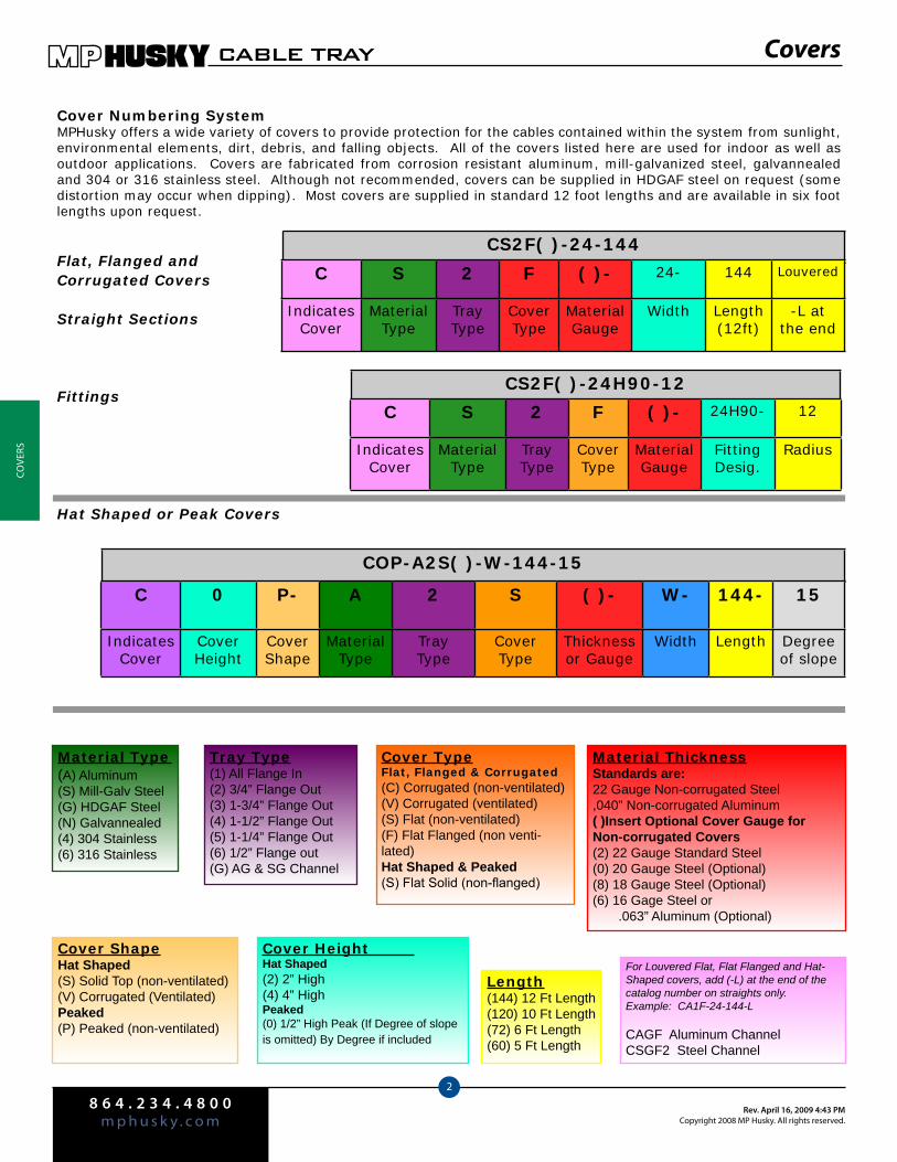
8 6 4 . 2 3 4 . 4 8 0 0m p h u s k y . c o m
Rev. April 16, 2009 4:43 PMCopyright 2008 MP Husky. All rights reserved.
CABLE TRAY
2
COve
rS
COP-A2S( )-W-144-15
CS2F( )-24-144
Covers
Cover Numbering SystemMPHusky offers a wide variety of covers to provide protection for the cables contained within the system from sunlight, environmental elements, dirt, debris, and falling objects. All of the covers listed here are used for indoor as well as outdoor applications. Covers are fabricated from corrosion resistant aluminum, mill-galvanized steel, galvannealed and 304 or 316 stainless steel. Although not recommended, covers can be supplied in HDGAF steel on request (some distortion may occur when dipping). Most covers are supplied in standard 12 foot lengths and are available in six foot lengths upon request.
C 0 P- A 2 S ( )- W- 144- 15
IndicatesCover
CoverHeight
CoverShape
MaterialType
TrayType
CoverType
Thicknessor Gauge
Width Length Degree of slope
For Louvered Flat, Flat Flanged and Hat-Shaped covers, add (-L) at the end of the catalog number on straights only.Example: CA1F-24-144-L
CAGF Aluminum ChannelCSGF2 Steel Channel
C S 2 F ( )- 24- 144 Louvered
Indicates Cover
MaterialType
TrayType
CoverType
MaterialGauge
Width Length(12ft)
-L at the end
Material Type (A) Aluminum (S) Mill-Galv Steel(G) HDGAF Steel(N) Galvannealed (4) 304 Stainless(6) 316 Stainless
Tray Type(1) All Flange In(2) 3/4” Flange Out(3) 1-3/4” Flange Out(4) 1-1/2” Flange Out(5) 1-1/4” Flange Out(6) 1/2” Flange out(G) AG & SG Channel
Cover TypeFlat, Flanged & Corrugated(C) Corrugated (non-ventilated)(V) Corrugated (ventilated)(S) Flat (non-ventilated)(F) Flat Flanged (non venti-lated)Hat Shaped & Peaked(S) Flat Solid (non-flanged)
Material ThicknessStandards are:22 Gauge Non-corrugated Steel,040” Non-corrugated Aluminum( )Insert Optional Cover Gauge forNon-corrugated Covers(2) 22 Gauge Standard Steel(0) 20 Gauge Steel (Optional)(8) 18 Gauge Steel (Optional)(6) 16 Gage Steel or .063” Aluminum (Optional)
Cover ShapeHat Shaped(S) Solid Top (non-ventilated)(V) Corrugated (Ventilated)Peaked(P) Peaked (non-ventilated)
Cover Height Hat Shaped(2) 2” High(4) 4” HighPeaked(0) 1/2” High Peak (If Degree of slope is omitted) By Degree if included
Length(144) 12 Ft Length(120) 10 Ft Length(72) 6 Ft Length(60) 5 Ft Length
Flat, Flanged and Corrugated Covers
Straight Sections
FittingsCS2F( )-24H90-12
C S 2 F ( )- 24H90- 12
Indicates Cover
MaterialType
TrayType
CoverType
MaterialGauge
FittingDesig.
Radius
Hat Shaped or Peak Covers
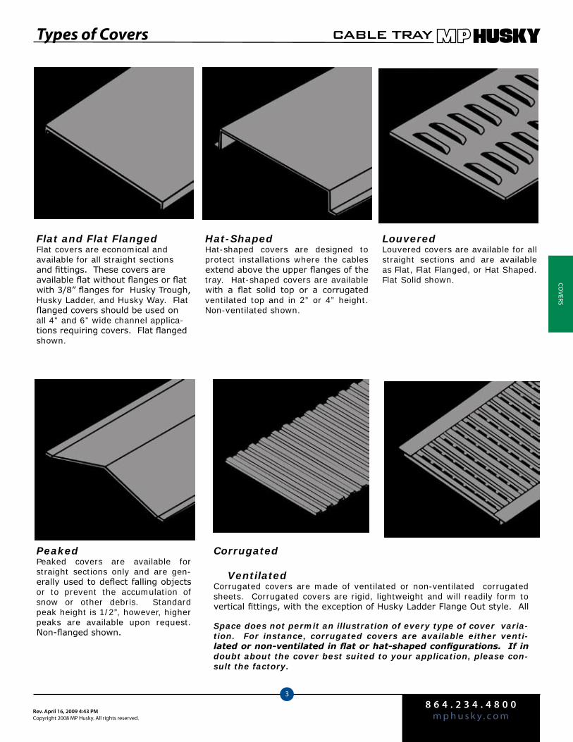
8 6 4 . 2 3 4 . 4 8 0 0m p h u s k y . c o mRev. April 16, 2009 4:43 PM
Copyright 2008 MP Husky. All rights reserved.
CABLE TRAY
3
COverS
Types of Covers
Flat and Flat FlangedFlat covers are economical and available for all straight sections and fittings. These covers are available flat without flanges or flat with 3/8” flanges for Husky Trough, Husky Ladder, and Husky Way. Flat flanged covers should be used on all 4” and 6” wide channel applica-tions requiring covers. Flat flanged shown.
Hat-ShapedHat-shaped covers are designed to protect installations where the cables extend above the upper flanges of the tray. Hat-shaped covers are available with a flat solid top or a corrugated ventilated top and in 2” or 4” height. Non-ventilated shown.
LouveredLouvered covers are available for all straight sections and are available as Flat, Flat Flanged, or Hat Shaped. Flat Solid shown.
PeakedPeaked covers are available for straight sections only and are gen-erally used to deflect falling objects or to prevent the accumulation of snow or other debris. Standard peak height is 1/2”, however, higher peaks are available upon request. Non-flanged shown.
Corrugated VentilatedCorrugated covers are made of ventilated or non-ventilated corrugated sheets. Corrugated covers are rigid, lightweight and will readily form to vertical fittings, with the exception of Husky Ladder Flange Out style. All
Space does not permit an illustration of every type of cover varia-tion. For instance, corrugated covers are available either venti-lated or non-ventilated in flat or hat-shaped configurations. If in doubt about the cover best suited to your application, please con-sult the factory.
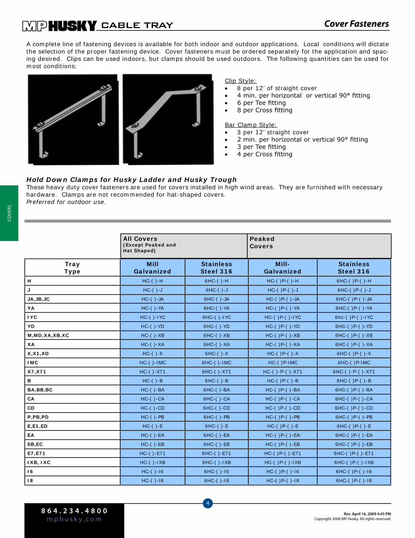
8 6 4 . 2 3 4 . 4 8 0 0m p h u s k y . c o m
Rev. April 16, 2009 4:43 PMCopyright 2008 MP Husky. All rights reserved.
CABLE TRAY
4
COve
rS
A complete line of fastening devices is available for both indoor and outdoor applications. Local conditions will dictate the selection of the proper fastening device. Cover fasteners must be ordered separately for the application and spac-ing desired. Clips can be used indoors, but clamps should be used outdoors. The following quantities can be used for most conditions:
Clip Style:8 per 12’ of straight cover •4 min. per horizontal or vertical 90° fitting •6 per Tee fitting •8 per Cross fitting •
Bar Clamp Style:3 per 12’ straight cover •2 min. per horizontal or vertical 90° fitting •3 per Tee fitting •4 per Cross fitting •
Tray Type
MillGalvanized
Stainless Steel 316
Mill-Galvanized
Stainless Steel 316
H HC-( )-H 6HC-( )-H HC-( )P-( )-H 6HC-( )P-( )-H
J HC-( )-J 6HC-( )-J HC-( )P-( )-J 6HC-( )P-( )-J
JA,JB,JC HC-( )-JA 6HC-( )-JA HC-( )P-( )-JA 6HC-( )P-( )-JA
YA HC-( )-YA 6HC-( )-YA HC-( )P-( )-YA 6HC-( )P-( )-YA
IYC HC-( )-IYC 6HC-( )-IYC HC-( )P-( )-IYC 6hc-( )P-( )-IYC
YD HC-( )-YD 6HC-( )-YD HC-( )P-( )-YD 6HC-( )P-( )-YD
M,MD,XA,XB,XC HC-( )-XB 6HC-( )-XB HC-( )P-( )-XB 6HC-( )P-( )-XB
XA HC-( )-XA 6HC-( )-XA HC-( )P-( )-XA 6HC-( )P-( )-XA
X,X1,XD HC-( )-X 6HC-( )-X HC-( )P-( )-X 6HC-( )P-( )-X
IMC HC-( )-IMC 6HC-( )-IMC HC-( )P-IMC 6HC-( )P-IMC
X7,X71 HC-( )-X71 6HC-( )-X71 HC-( )-P-( )-X71 6HC-( )-P-( )-X71
B HC-( )-B 6HC-( )-B HC-( )P-( )-B 6HC-( )P-( )-B
BA,BB,BC HC-( )-BA 6HC-( )-BA HC-( )P-( )-BA 6HC-( )P-( )-BA
CA HC-( )-CA 6HC-( )-CA HC-( )P-( )-CA 6HC-( )P-( )-CA
CD HC-( )-CD 6HC-( )-CD HC-( )P-( )-CD 6HC-( )P-( )-CD
P,PB,PD HC-( )-PB 6HC-( )-PB HC-( )P-( )-PB 6HC-( )P-( )-PB
E,E1,ED HC-( )-E 6HC-( )-E HC-( )P-( )-E 6HC-( )P-( )-E
EA HC-( )-EA 6HC-( )-EA HC-( )P-( )-EA 6HC-( )P-( )-EA
EB,EC HC-( )-EB 6HC-( )-EB HC-( )P-( )-EB 6HC-( )P-( )-EB
E7,E71 HC-( )-E71 6HC-( )-E71 HC-( )P-( )-E71 6HC-( )P-( )-E71
IXB, IXC HC-( )-IXB 6HC-( )-IXB HC-( )P-( )-IXB 6HC-( )P-( )-IXB
I6 HC-( )-I6 6HC-( )-I6 HC-( )P-( )-I6 6HC-( )P-( )-I6
I8 HC-( )-I8 6HC-( )-I8 HC-( )P-( )-I8 6HC-( )P-( )-I8
All Covers(Except Peaked and Hat Shaped)
PeakedCovers
Hold Down Clamps for Husky Ladder and Husky TroughThese heavy duty cover fasteners are used for covers installed in high wind areas. They are furnished with necessary hardware. Clamps are not recommended for hat-shaped covers. Preferred for outdoor use.
Cover Fasteners

8 6 4 . 2 3 4 . 4 8 0 0m p h u s k y . c o mRev. April 16, 2009 4:43 PM
Copyright 2008 MP Husky. All rights reserved.
CABLE TRAY
5
COverS
Cover Clips for Flange Out Husky LadderThis cover clip is designed to fasten the Electray covers (flange out) shown in this section. Each clip is mill-galvanized steel and furnished with a thumb screw to facilitate inverted installation on flanged covers.
Top Flange Plated Steel
3/4” ECC 6ECC
All Others ECC-E 6ECC-E
Cover Clips for Flange In Husky Ladder and Husky TroughThese clips fasten the Husky Trough and Husky Flange In Ladder covers shown in this section to Husky Trough and Husky Flange In Ladder.
Tray Type Pl. Steel SS 316
H VCC 6VCC
J JCC 6JCC
JA, JB, JC KCC 6KCC
YA YACC 6YACC
YD YDCC 6YDCC
M, MB, MD MCC 6MCC
X, X1 XCC 6XCC
MC, XB, XC XBCC 6XBCC
XA XACC 6XACC
XD XDCC 6XDCC
X7,X71 X7ICC 6X7ICC
Banding, Banding Clips and Banding ToolsAll covers, except peaked & hat-shaped may be secured with banding. Stainless steel banding is available with banding clips. Banding is 0.02” x 1/2” wide type 302 Stainless Steel strip. Clips are used to secure banding. Only a piece of wood and a pair of pliers are required to tighten and fasten in place, although a special banding tool is available for this purpose. The banding tool is used when a consid-erable amount of banding is to be done or when uniform tensioning of the banding is desirable. This tool has a built-in cut-off and extremely short (6”) handles with aluminum knobs for use in tight quarters. The 36-tooth ratchet creates high ten-sioning power. *Banding clips are each.
Description Catalog No.
100’ Roll 1/2” Wide Banding
SCCB-100
Banding Clips 1/2” Wide SCCB-C
Banding Tool CCB-T
Cover Fasteners

8 6 4 . 2 3 4 . 4 8 0 0m p h u s k y . c o m
Rev. April 16, 2009 4:43 PMCopyright 2008 MP Husky. All rights reserved.
CABLE TRAY
6
COve
rS
Stand-Off Clips and Support Blocks
Cover stand-off clips provide a means to mount the cover above the tray side rail, allowing side ventilation. Cover stand-off clips should only be used with flanged cov-ers and are available in various heights, offering a choice in the amount of open area for side ventilation.(Part # is for 1ea.)
Please Note: ( ) = Insert Height In Inches
Tray Type
Plated Steel
StainlessSteel 316
H,J,M,JA,JB,JC, MB, MD RCC-J-( ) 6RCC-J-( )
YA,MC,X,X1,YD,XB,XC,XD,X7,X71,IMC RCC-X-( ) 6RCC-X-( )
All Flange Out Husky Ladder BA,BB,CA,PB,PC,E,E1,B,BC,CD,P,PD,EB,EC, ED,, E7,E71,I6,I8
RCC-E-( ) 6RCC-E-( )
IYC, IMC, IXB, IXC RCC-I-( ) 6RCC-I-( )
Support BlocksCable Support Blocks are designed for clamping cables in locations approved by the National Electrical Code. The width and number of holes can be made to your requirements. Blocks are made from kiln dried select grade hardrock maple. Af-ter fabrication, block segments are treated with a wood preservative and painted with light grey outdoor paint. Each support block is furnished with the required number of non-magnetic threaded studs, complete with nuts and flat washers.
When ordering, indicate tray width, number of cables, conductor size, voltage and exact outside diameter of the cable. Blocks are not for use in Husky Trough.
Peak Cover End PlateUsed to close the end of a peaked cover where it ends against a flat cover.
Catalog # ExampleC ( ) P—Prefix—(Width)—EP—( )
C ( ) P = Insert peak in inches 0 = 1/2” peak, 1 = 1” peak, etc.
EP-( ) = Insert degrees if cover has peak in degrees
Cover Joint Strips
Aluminum Flange In Husky Ladder-ASP-VS-(Width)Flange Out Husky Ladder-ASP-ES-(Width)
Steel Flange In Husky Ladder-SSP-VS-(Width)Flange Out Husky Ladder-SSP-ES-(Width)
Galvannealled Husky Way NSP-VS-(Width)
Cover Fastening ScrewsAll covers may be secured with self-drilling tapping sheet metal screws (shown above).
Description Catalog #
#10 x 5/8” Hex Head Self Drilling Self Tapping Stainless Steel
B-55-SS
#6-20 x 3/8” Self Drilling Phillips Pan Head Sheet Metal Screw
B-26

America’s Leading Manufacturer of Cable Tray and Cable Bus
TECHTRAYEDUCATION INDUSTRIAL TELECOM / DATA CENTERS COMMERCIAL
Smart Cable Management
8 6 4 . 2 3 4 . 4 8 0 0m p h u s k y . c o m
Rev. April 14, 2009 12:39 PMCopyright 2008 MP Husky. All rights reserved.
Techtray
13-2
Table of Contents
Introduction..................................... Pg. 14.3
Quality Information.......................Pg. 14.4
Features & Benefits........................Pg. 14.5
Fill Chart / Load Tests....................Pg. 14.6
Numbering System....................... Pg. 14.7
Connectors & Fittings...................Pgs. 14.8-14.10
Cutting the Wire Basket...............Pgs. 14.11-14.14
Supports & Covers......................... Pgs. 14.15-14.17
Accessories........................................Pgs. 14.18-14.21
Smart Tab........................................... Pg. 14.22
Sample System Layout................Pg. 14.23
MPHusky Techtray is.......
“Smart Cable Management!”

8 6 4 . 2 3 4 . 4 8 0 0m p h u s k y . c o mRev. April 14, 2009 12:39 PM
Copyright 2008 MP Husky. All rights reserved.
Techtray
13-3
IntroductionMPHusky has been in the Cable Tray business since 1955. Over the past 50+ years of leadership and service, MPHusky has gone through several transformations and mergers, including Husky/Burndy and Metal Products, thus leading to what is today MPHusky—America’s leading manufacturer of Cable Tray and Cable Bus Power Distribution Systems.
Throughout these changes one thing has remained constant—the “Husky” drive to be the most reliable, highest quality, cost effective and innovative manufacturer of Cable Support Systems and Cable Bus Power Distribution Systems. We have an unsurpassed commitment to customer satisfaction and service, and we are eager to earn your loyalty and trust.
Suggested Techtray Specification
Product Description: • Techtray is a wire mesh cable tray system that utilizes high mechanical strength steel wire that is welded into a grid system. This grid system is then formed into channels which support and carry cables. The wire mesh will consist of a 2” x 2” grid system, and will utilize wires that have a minimum diameter of .16” (4mm).Material:• Standard tray finish shall be mill-galvanized. Other finish options include Electroplated Zinc, Hot Dipped Galvanized after Fabrication, Yellow Zinc Dichromate, Painted or Stainless Steel.Safety Edge: • Wire mesh system shall have continuous top edge wire that is T-Welded on top of support wires to avoid sharp edges that may damage cable or installer.Fittings:• Shall be fabricated in the field by cutting wires with a cutting device. Cuts shall be made in a manner reducing sharp edges and projections so they do not harm cables or installation personnel. Manufacturer shall offer corner connectors that provide Straight sections shall be provided in 10’ (3m) lengths.•Wire mesh shall be welded at all intersections.•Mesh system will permit continuous ventilation of cables and maximum disposition of heat.•Tray shall be manufactured in accordance with NEMA VE-1 and shall be installed in accordance with NEMA •VE-2.

8 6 4 . 2 3 4 . 4 8 0 0m p h u s k y . c o m
Rev. April 14, 2009 12:39 PMCopyright 2008 MP Husky. All rights reserved.
Techtray
13-4
QualityOur Quality Policy
At MPHusky we are committed to producing only the highest quality products that meet or exceed our cus-tomers’ expectations and requirements. Our goal is to achieve 100% customer satisfaction by delivering the best products and services on-time and defect free. We will achieve this individually and corporately through tested and proven processes and controls, in our Quality System, and with a constant focus and effort on continuous improvement.
Item Standards
MPHusky Quality Program ANSI / ASQC Q9001-2000 (ISO 9001 Compliant)•ASME NQA-1-2004•ANSI N45.2•
Certification CSA Certified
Load Test Standards NEMA VE-1/CSA Tray Standards
“MPHusky Techtray is truly ‘Smart Cable Management’. It is simple, fast to install, and very cost effective. The ‘T-Weld’ safety edge, as well as the strong and modular 2” x 2” grid design make Techtray perfect for handling sensitive cables. Another great benefit is there are no custom fittings and very few accessories for installation.”
Industrial Electrical Contractor
Customer Testimonial
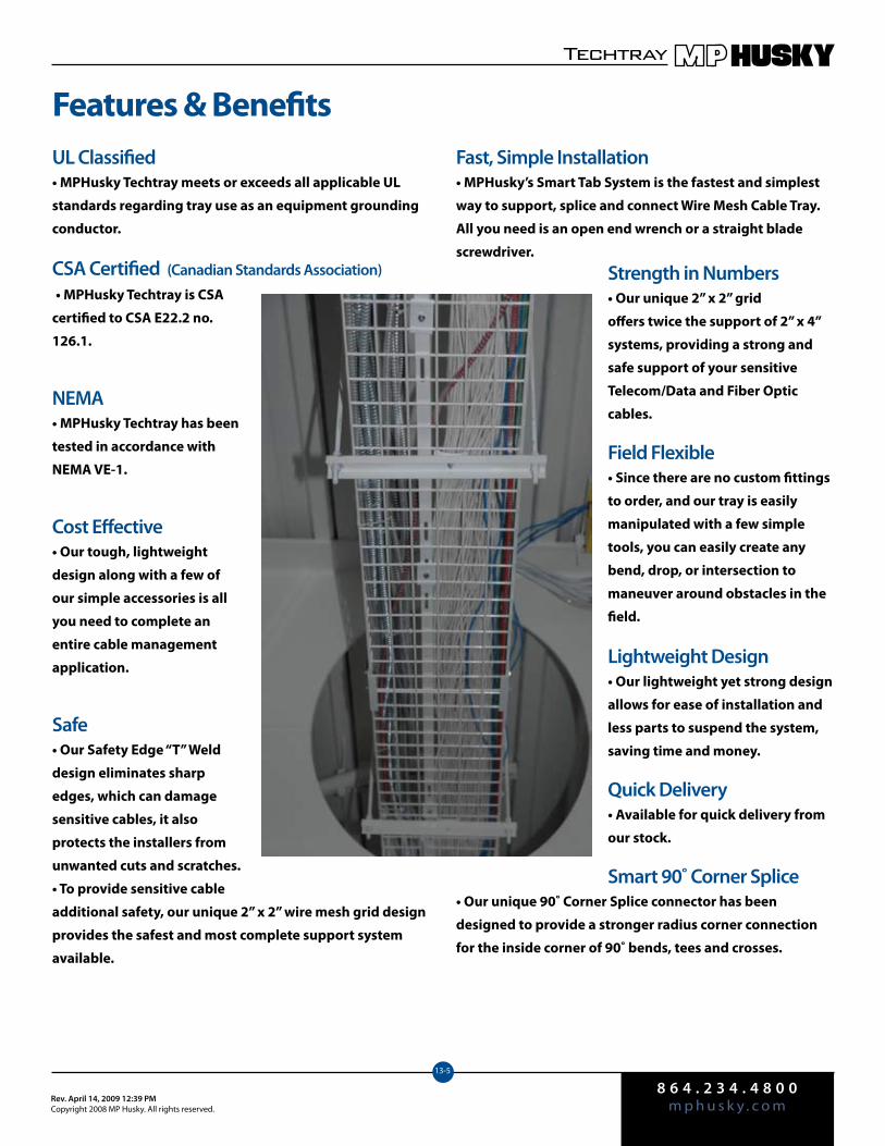
8 6 4 . 2 3 4 . 4 8 0 0m p h u s k y . c o mRev. April 14, 2009 12:39 PM
Copyright 2008 MP Husky. All rights reserved.
Techtray
13-5
Features & BenefitsFast, Simple Installation• MPHusky’s Smart Tab System is the fastest and simplest
way to support, splice and connect Wire Mesh Cable Tray.
All you need is an open end wrench or a straight blade
screwdriver.
Strength in Numbers• Our unique 2” x 2” grid
offers twice the support of 2” x 4”
systems, providing a strong and
safe support of your sensitive
Telecom/Data and Fiber Optic
cables.
Field Flexible• Since there are no custom fittings
to order, and our tray is easily
manipulated with a few simple
tools, you can easily create any
bend, drop, or intersection to
maneuver around obstacles in the
field.
Lightweight Design• Our lightweight yet strong design
allows for ease of installation and
less parts to suspend the system,
saving time and money.
Quick Delivery• Available for quick delivery from
our stock.
Smart 90˚ Corner Splice• Our unique 90˚ Corner Splice connector has been
designed to provide a stronger radius corner connection
for the inside corner of 90˚ bends, tees and crosses.
UL Classified• MPHusky Techtray meets or exceeds all applicable UL
standards regarding tray use as an equipment grounding
conductor.
CSA Certified (Canadian Standards Association) • MPHusky Techtray is CSA
certified to CSA E22.2 no.
126.1.
NEMA• MPHusky Techtray has been
tested in accordance with
NEMA VE-1.
Cost Effective• Our tough, lightweight
design along with a few of
our simple accessories is all
you need to complete an
entire cable management
application.
Safe• Our Safety Edge “T” Weld
design eliminates sharp
edges, which can damage
sensitive cables, it also
protects the installers from
unwanted cuts and scratches.
• To provide sensitive cable
additional safety, our unique 2” x 2” wire mesh grid design
provides the safest and most complete support system
available.
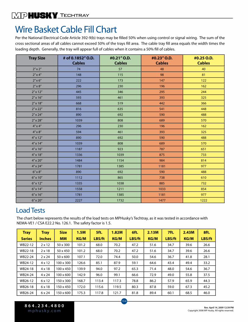
8 6 4 . 2 3 4 . 4 8 0 0m p h u s k y . c o m
Rev. April 14, 2009 12:39 PMCopyright 2008 MP Husky. All rights reserved.
Techtray
13-6
Wire Basket Cable Fill ChartPer the National Electrical Code Article 392-9(b) trays may be filled 50% when using control or signal wiring. The sum of the cross sectional areas of all cables cannot exceed 50% of the trays fill area. The cable tray fill area equals the width times the loading depth. Generally, the tray will appear full of cables when it contains a 50% fill of cables.
Load Tests
Tray Tray Size 1.5M 5ft. 1.82M 6ft. 2.13M 7ft. 2.43M 8ft.
Series Inches MM KG/M LBS/ft KG/M LBS/ft KG/M LBS/ft KG/M LBS/ftWB22-12 2 x 12 50 x 300 101.2 68.0 70.2 47.2 51.6 34.7 39.6 26.6
WB22-18 2 x 18 50 x 450 101.2 68.0 70.2 47.2 51.6 34.7 39.6 26.6
WB22-24 2 x 24 50 x 600 107.1 72.0 74.4 50.0 54.6 36.7 41.8 28.1
WB24-12 4 x 12 100 x 300 126.6 85.1 87.9 59.1 64.6 43.4 49.4 33.2
WB24-18 4 x 18 100 x 450 139.9 94.0 97.2 65.3 71.4 48.0 54.6 36.7
WB24-24 4 x 24 100 x 600 142.9 96.0 99.1 66.6 72.9 49.0 55.8 37.5
WB26-12 6 x 12 150 x 300 168.7 113.4 117.3 78.8 86.2 57.9 65.9 44.3
WB26-18 6 x 18 150 x 450 172.0 115.6 119.5 80.3 87.8 59.0 67.3 45.2
WB26-24 6 x 24 150 x 600 175.3 117.8 121.7 81.8 89.4 60.1 68.5 46.0
The chart below represents the results of the load tests on MPHusky’s Techtray, as it was tested in accordance with NEMA-VE1 / CSA E22.2 No. 126.1. The safety factor is 1.5.
Tray Size # of 0.1852” O.D. Cables
#0.21” O.D. Cables
#0.23” O.D. Cables
#0.25 O.D. Cables
2” x 2” 74 57 48 40
2” x 4” 148 115 98 81
2” x 6” 222 173 147 122
2” x 8” 296 230 196 162
2” x 12” 445 346 295 244
2” x 16” 593 461 393 325
2” x 18” 668 519 442 366
2” x 22” 816 635 541 448
2” x 24” 890 692 590 488
2” x 28” 1039 808 689 570
4” x 4” 296 230 196 162
4” x 8” 594 461 393 325
4” x 12” 890 692 590 488
4” x 14” 1039 808 689 570
4” x 16” 1187 923 787 651
4” x 18” 1336 1039 875 733
4” x 20” 1484 1154 984 814
4” x 24” 1781 1385 1181 977
6” x 8” 890 692 590 488
6” x 10” 1112 865 738 610
6” x 12” 1335 1038 885 732
6” x 14” 1558 1211 1033 854
6” x 16” 1781 1385 1181 977
6” x 20” 2227 1732 1477 1222
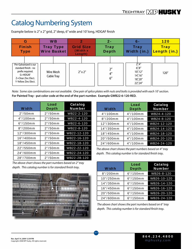
8 6 4 . 2 3 4 . 4 8 0 0m p h u s k y . c o mRev. April 14, 2009 12:39 PM
Copyright 2008 MP Husky. All rights reserved.
Techtray
13-7
Catalog Numbering SystemExample below is 2” x 2” grid, 2” deep, 6” wide and 10’ long, HDGAF finish
G WB 2 2- 6- 120FinishType
Tray TypeWire Basket
Grid Size(Width x Length)
TrayDepth
TrayWidth (in.)
TrayLength (in.)
Pre-Galvanized is our standard finish - no
prefix required.G=HDGAF
Z=Clear Zinc Elect.Y-Yellow Zinc Elect.
Wire MeshCable Tray
2” x 2”
2”4”6”
2”, 4”6”, 8”
10”, 12”14”, 16”18”, 20”22”, 24”
120”
Note: Some size combinations are not available. One pair of splice plates with nuts and bolts is provided with each 10’ section.For Painted Tray - put color code at the end of the part number. Example GWB22-6-120-RED.
WidthLoadDepth
CatalogNumber
2”/50mm 2”/50mm WB22-2-120
4”/100mm 2”/50mm WB22-4-120
6”/150mm 2”/50mm WB22-6-120
8”/200mm 2”/50mm WB22-8-120
12”/300mm 2”/50mm WB22-12-120
16”/400mm 2”/50mm WB22-16-120
18”/450mm 2”/50mm WB22-18-120
22”/550mm 2”/50mm WB22-22-120
24”/600mm 2”/50mm WB22-24-120
28”/700mm 2”/50mm WB22-28-120
WidthLoadDepth
CatalogNumber
4”/100mm 4”/100mm WB24-4-120
8”/200mm 4”/100mm WB24-8-120
12”/300mm 4”/100mm WB24-12-120
14”/350mm 4”/100mm WB24-14-120
18”/450mm 4”/100mm WB24-18-120
20”/500mm 4”/100mm WB24-20-120
24”/600mm 4”/100mm WB24-24-120
WidthLoadDepth
CatalogNumber
8”/200mm 6”/150mm WB26-8-120
10”/250mm 6”/150mm WB26-10-120
14”/350mm 6”/150mm WB26-14-120
16”/450mm 6”/150mm WB26-16-120
20”/500mm 6”/150mm WB26-20-120
24”/600mm 6”/150mm WB26-24-120
The above chart shows the part numbers based on 2” tray depth. This catalog number is for standard finish tray.
The above chart shows the part numbers based on 4” tray depth. This catalog number is for standard finish tray.
The above chart shows the part numbers based on 6” tray depth. This catalog number is for standard finish tray.
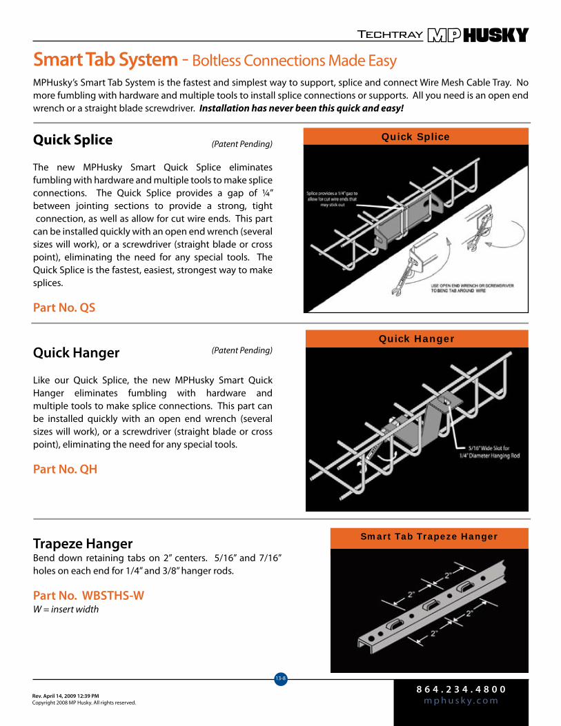
8 6 4 . 2 3 4 . 4 8 0 0m p h u s k y . c o mRev. April 14, 2009 12:39 PM
Copyright 2008 MP Husky. All rights reserved.
Techtray
13-8
Quick Splice
Smart Tab System - Boltless Connections Made Easy
Trapeze HangerBend down retaining tabs on 2” centers. 5/16” and 7/16” holes on each end for 1/4” and 3/8” hanger rods.
Part No. WBSTHS-WW = insert width
Smart Tab Trapeze Hanger
Quick Splice
The new MPHusky Smart Quick Splice eliminates fumbling with hardware and multiple tools to make splice connections. The Quick Splice provides a gap of ¼” between jointing sections to provide a strong, tight connection, as well as allow for cut wire ends. This part can be installed quickly with an open end wrench (several sizes will work), or a screwdriver (straight blade or cross point), eliminating the need for any special tools. The Quick Splice is the fastest, easiest, strongest way to make splices.
Part No. QS
Quick HangerQuick Hanger
Like our Quick Splice, the new MPHusky Smart Quick Hanger eliminates fumbling with hardware and multiple tools to make splice connections. This part can be installed quickly with an open end wrench (several sizes will work), or a screwdriver (straight blade or cross point), eliminating the need for any special tools.
Part No. QH
(Patent Pending)
(Patent Pending)
MPHusky’s Smart Tab System is the fastest and simplest way to support, splice and connect Wire Mesh Cable Tray. No more fumbling with hardware and multiple tools to install splice connections or supports. All you need is an open end wrench or a straight blade screwdriver. Installation has never been this quick and easy!
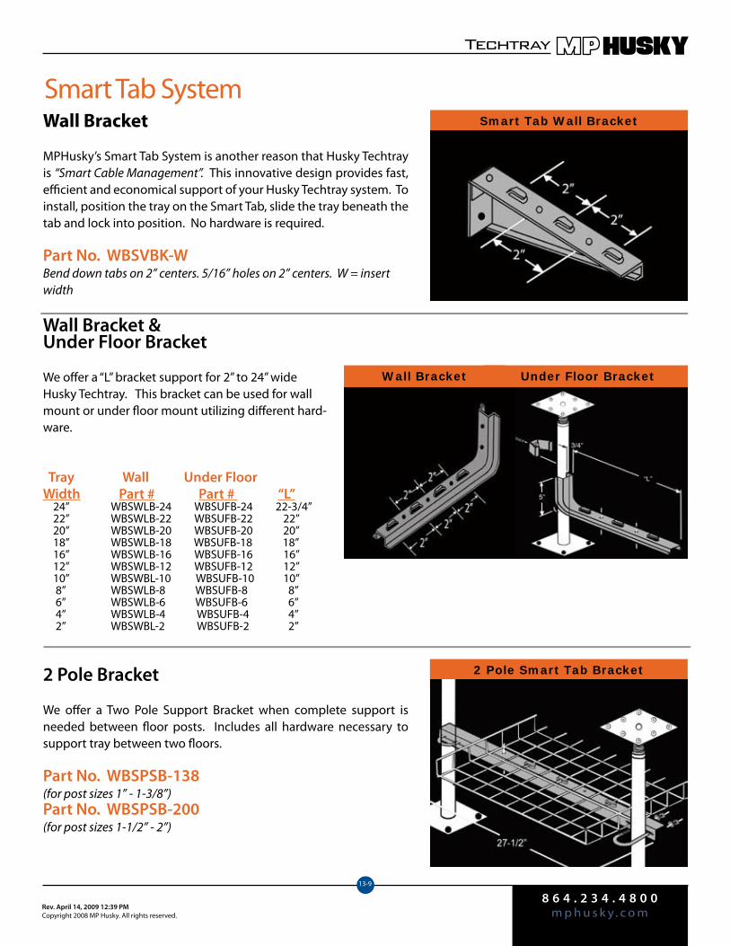
8 6 4 . 2 3 4 . 4 8 0 0m p h u s k y . c o mRev. April 14, 2009 12:39 PM
Copyright 2008 MP Husky. All rights reserved.
Techtray
13-9
Wall Bracket &Under Floor Bracket
We offer a “L” bracket support for 2” to 24” wide Husky Techtray. This bracket can be used for wall mount or under floor mount utilizing different hard-ware.
Tray Wall Under FloorWidth Part # Part # “L” 24” WBSWLB-24 WBSUFB-24 22-3/4” 22” WBSWLB-22 WBSUFB-22 22” 20” WBSWLB-20 WBSUFB-20 20” 18” WBSWLB-18 WBSUFB-18 18” 16” WBSWLB-16 WBSUFB-16 16” 12” WBSWLB-12 WBSUFB-12 12” 10” WBSWBL-10 WBSUFB-10 10” 8” WBSWLB-8 WBSUFB-8 8” 6” WBSWLB-6 WBSUFB-6 6” 4” WBSWLB-4 WBSUFB-4 4” 2” WBSWBL-2 WBSUFB-2 2”
Smart Tab Wall Bracket
2 Pole Smart Tab Bracket
Smart Tab System
2 Pole Bracket
We offer a Two Pole Support Bracket when complete support is needed between floor posts. Includes all hardware necessary to support tray between two floors.
Part No. WBSPSB-138(for post sizes 1” - 1-3/8”)Part No. WBSPSB-200(for post sizes 1-1/2” - 2”)
Wall Bracket
MPHusky’s Smart Tab System is another reason that Husky Techtray is “Smart Cable Management”. This innovative design provides fast, efficient and economical support of your Husky Techtray system. To install, position the tray on the Smart Tab, slide the tray beneath the tab and lock into position. No hardware is required.
Part No. WBSVBK-WBend down tabs on 2” centers. 5/16” holes on 2” centers. W = insert width
Under Floor BracketWall Bracket
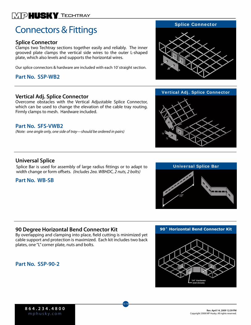
8 6 4 . 2 3 4 . 4 8 0 0m p h u s k y . c o m
Rev. April 14, 2009 12:39 PMCopyright 2008 MP Husky. All rights reserved.
Techtray
13-10
Vertical Adj. Splice Connector
Splice Connector
Connectors & FittingsSplice ConnectorClamps two Techtray sections together easily and reliably. The inner grooved plate clamps the vertical side wires to the outer L-shaped plate, which also levels and supports the horizontal wires.
Our splice connectors & hardware are included with each 10’ straight section.
Part No. SSP-WB2
Vertical Adj. Splice ConnectorOvercome obstacles with the Vertical Adjustable Splice Connector, which can be used to change the elevation of the cable tray routing. Firmly clamps to mesh. Hardware included.
Part No. SFS-VWB2(Note: one angle only, one side of tray—should be ordered in pairs)
Universal Splice
Part No. WB-SB
90 Degree Horizontal Bend Connector KitBy overlapping and clamping into place, field cutting is minimized yet cable support and protection is maximized. Each kit includes two back plates, one “L” corner plate, nuts and bolts.
Part No. SSP-90-2
Splice Bar is used for assembly of large radius fittings or to adapt to width change or form offsets. (Includes 2ea. WBHDC, 2 nuts, 2 bolts)
Universal Splice Bar
90˚ Horizontal Bend Connector Kit
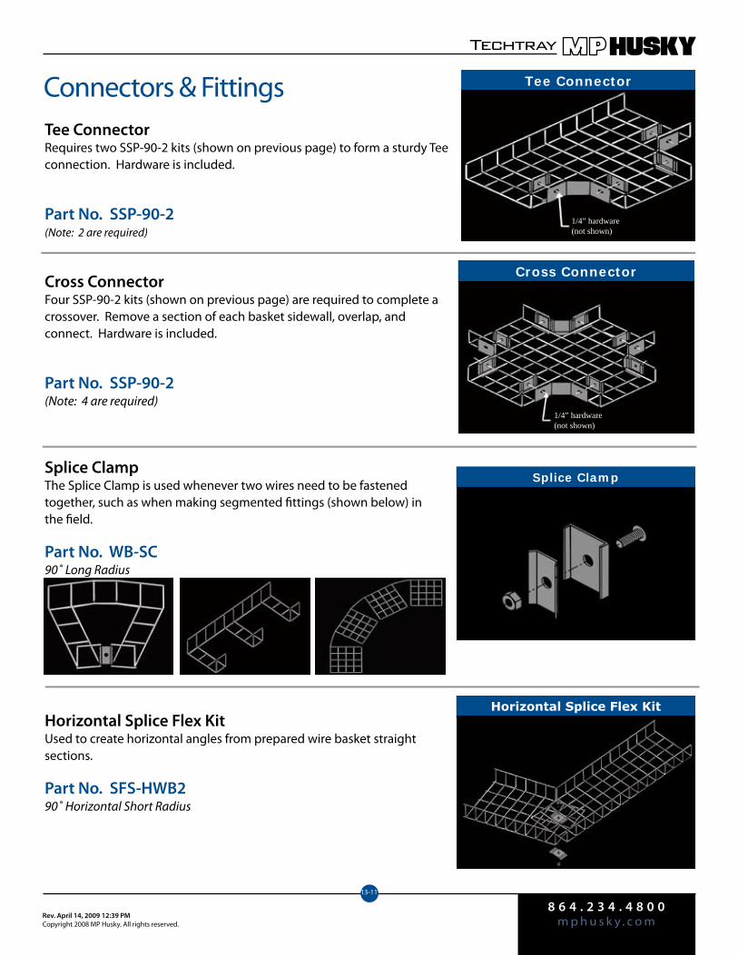
8 6 4 . 2 3 4 . 4 8 0 0m p h u s k y . c o mRev. April 14, 2009 12:39 PM
Copyright 2008 MP Husky. All rights reserved.
Techtray
13-11
Connectors & FittingsTee ConnectorRequires two SSP-90-2 kits (shown on previous page) to form a sturdy Tee connection. Hardware is included.
Part No. SSP-90-2(Note: 2 are required)
Cross ConnectorFour SSP-90-2 kits (shown on previous page) are required to complete a crossover. Remove a section of each basket sidewall, overlap, and connect. Hardware is included.
Part No. SSP-90-2(Note: 4 are required)
Splice ClampThe Splice Clamp is used whenever two wires need to be fastened together, such as when making segmented fittings (shown below) in the field.
Part No. WB-SC90˚ Long Radius
Horizontal Splice Flex KitUsed to create horizontal angles from prepared wire basket straight sections.
Part No. SFS-HWB290˚ Horizontal Short Radius
Tee Connector
Splice Clamp
Cross Connector
Horizontal Splice Flex Kit
1/4” hardware (not shown)
1/4” hardware (not shown)
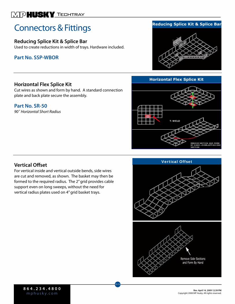
8 6 4 . 2 3 4 . 4 8 0 0m p h u s k y . c o m
Rev. April 14, 2009 12:39 PMCopyright 2008 MP Husky. All rights reserved.
Techtray
13-12
Connectors & FittingsReducing Splice Kit & Splice BarUsed to create reductions in width of trays. Hardware included.
Part No. SSP-WBOR
Horizontal Flex Splice KitCut wires as shown and form by hand. A standard connectionplate and back plate secure the assembly.
Part No. SR-5090˚ Horizontal Short Radius
Vertical OffsetFor vertical inside and vertical outside bends, side wires are cut and removed, as shown. The basket may then be formed to the required radius. The 2” grid provides cable support even on long sweeps, without the need for vertical radius plates used on 4” grid basket trays.
Horizontal Flex Splice Kit
REMOVE SECTION AND FORM BY HAND—OVERLAPPING ONE SECTION
T-WELD
Vertical Offset
Reducing Splice Kit & Splice Bar
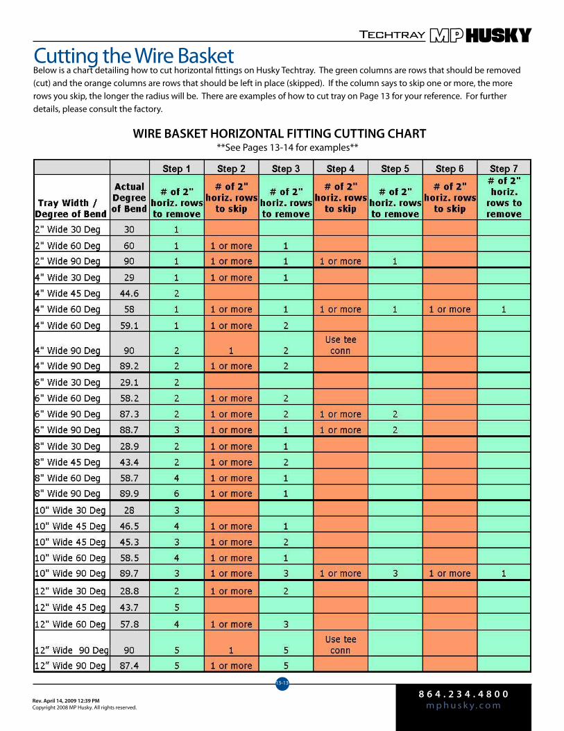
8 6 4 . 2 3 4 . 4 8 0 0m p h u s k y . c o mRev. April 14, 2009 12:39 PM
Copyright 2008 MP Husky. All rights reserved.
Techtray
13-13
Cutting the Wire BasketBelow is a chart detailing how to cut horizontal fittings on Husky Techtray. The green columns are rows that should be removed (cut) and the orange columns are rows that should be left in place (skipped). If the column says to skip one or more, the more rows you skip, the longer the radius will be. There are examples of how to cut tray on Page 13 for your reference. For further details, please consult the factory.
WIRE BASKET HORIZONTAL FITTING CUTTING CHART **See Pages 13-14 for examples**
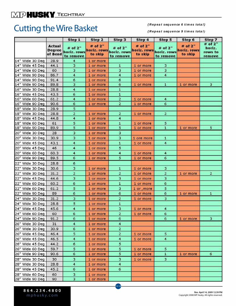
8 6 4 . 2 3 4 . 4 8 0 0m p h u s k y . c o m
Rev. April 14, 2009 12:39 PMCopyright 2008 MP Husky. All rights reserved.
Techtray
13-14
Cutting the Wire Basket(Repeat sequence 6 times total)
(Repeat sequence 9 times total )
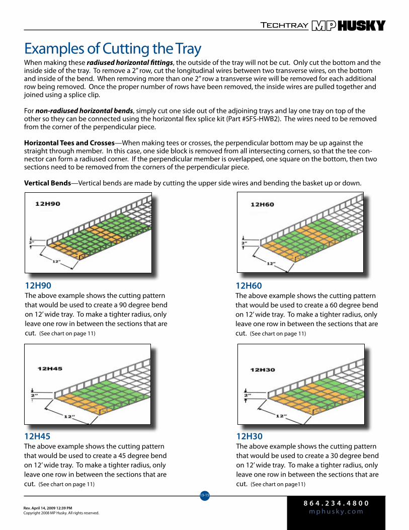
8 6 4 . 2 3 4 . 4 8 0 0m p h u s k y . c o mRev. April 14, 2009 12:39 PM
Copyright 2008 MP Husky. All rights reserved.
Techtray
13-15
Examples of Cutting the TrayWhen making these radiused horizontal fittings, the outside of the tray will not be cut. Only cut the bottom and the inside side of the tray. To remove a 2” row, cut the longitudinal wires between two transverse wires, on the bottom and inside of the bend. When removing more than one 2” row a transverse wire will be removed for each additional row being removed. Once the proper number of rows have been removed, the inside wires are pulled together and joined using a splice clip.
For non-radiused horizontal bends, simply cut one side out of the adjoining trays and lay one tray on top of the other so they can be connected using the horizontal flex splice kit (Part #SFS-HWB2). The wires need to be removed from the corner of the perpendicular piece.
Horizontal Tees and Crosses—When making tees or crosses, the perpendicular bottom may be up against the straight through member. In this case, one side block is removed from all intersecting corners, so that the tee con-nector can form a radiused corner. If the perpendicular member is overlapped, one square on the bottom, then two sections need to be removed from the corners of the perpendicular piece.
Vertical Bends—Vertical bends are made by cutting the upper side wires and bending the basket up or down.
12H90The above example shows the cutting patternthat would be used to create a 90 degree bend on 12’ wide tray. To make a tighter radius, onlyleave one row in between the sections that arecut. (See chart on page 11)
12H60The above example shows the cutting pattern that would be used to create a 60 degree bend on 12’ wide tray. To make a tighter radius, only leave one row in between the sections that are cut. (See chart on page 11)
12H45The above example shows the cutting pattern that would be used to create a 45 degree bend on 12’ wide tray. To make a tighter radius, only leave one row in between the sections that are cut. (See chart on page 11)
12H30The above example shows the cutting pattern that would be used to create a 30 degree bend on 12’ wide tray. To make a tighter radius, only leave one row in between the sections that are cut. (See chart on page11)
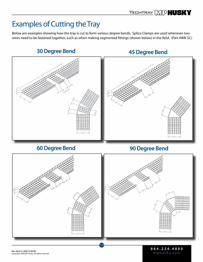
8 6 4 . 2 3 4 . 4 8 0 0m p h u s k y . c o mRev. April 14, 2009 12:39 PM
Copyright 2008 MP Husky. All rights reserved.
Techtray
13-16
Examples of Cutting the TrayBelow are examples showing how the tray is cut to form various degree bends. Splice Clamps are used whenever two wires need to be fastened together, such as when making segmented fittings (shown below) in the field. (Part #WB-SC)
30 Degree Bend 45 Degree Bend
60 Degree Bend 90 Degree Bend
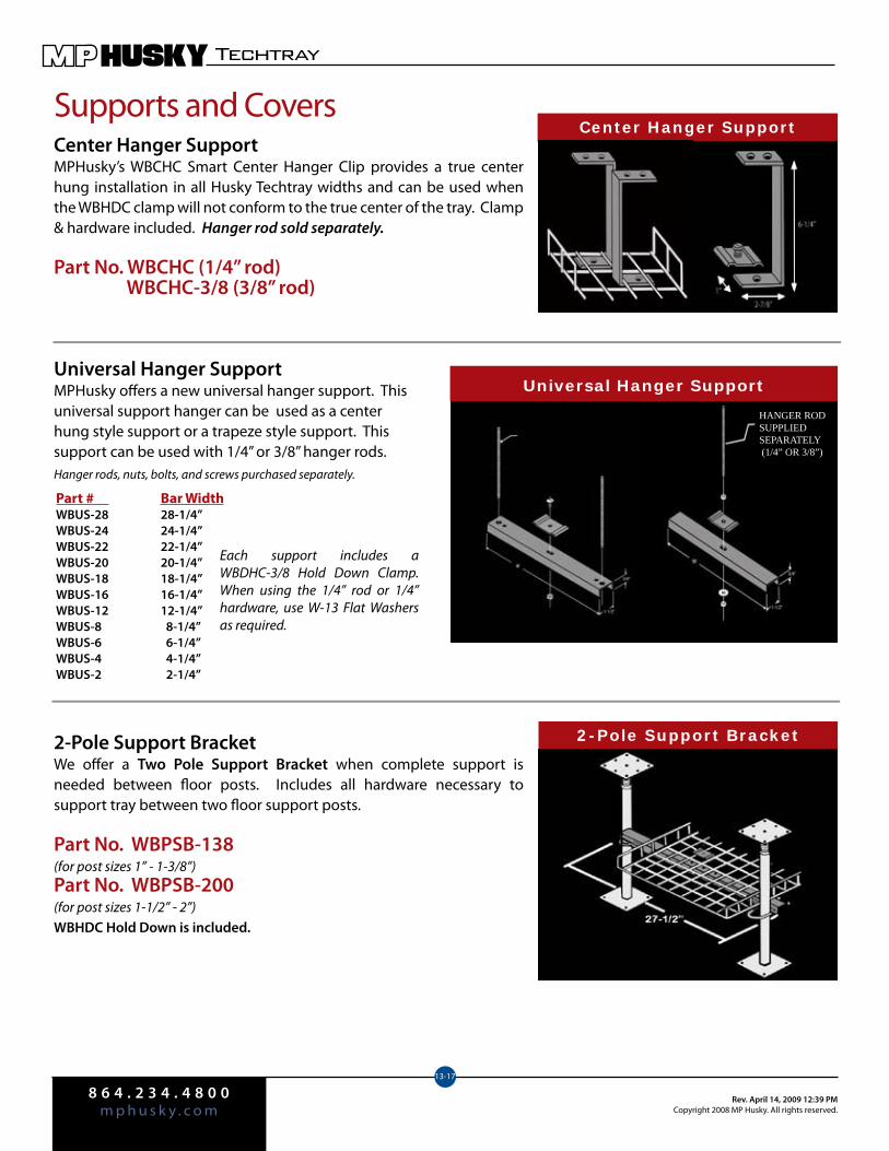
8 6 4 . 2 3 4 . 4 8 0 0m p h u s k y . c o m
Rev. April 14, 2009 12:39 PMCopyright 2008 MP Husky. All rights reserved.
Techtray
13-17
Supports and CoversCenter Hanger SupportMPHusky’s WBCHC Smart Center Hanger Clip provides a true center hung installation in all Husky Techtray widths and can be used when the WBHDC clamp will not conform to the true center of the tray. Clamp & hardware included. Hanger rod sold separately.
Part No. WBCHC (1/4” rod) WBCHC-3/8 (3/8” rod)
Universal Hanger SupportMPHusky offers a new universal hanger support. This universal support hanger can be used as a center hung style support or a trapeze style support. This support can be used with 1/4” or 3/8” hanger rods. Hanger rods, nuts, bolts, and screws purchased separately.
2-Pole Support BracketWe offer a Two Pole Support Bracket when complete support is needed between floor posts. Includes all hardware necessary to support tray between two floor support posts.
Part No. WBPSB-138(for post sizes 1” - 1-3/8”)Part No. WBPSB-200(for post sizes 1-1/2” - 2”)WBHDC Hold Down is included.
Center Hanger Support
Part # Bar WidthWBUS-28 28-1/4”WBUS-24 24-1/4”WBUS-22 22-1/4”WBUS-20 20-1/4”WBUS-18 18-1/4”WBUS-16 16-1/4”WBUS-12 12-1/4”WBUS-8 8-1/4”WBUS-6 6-1/4”WBUS-4 4-1/4”WBUS-2 2-1/4”
HANGER ROD SUPPLIED SEPARATELY (1/4” OR 3/8”)
2-Pole Support Bracket
Universal Hanger Support
Each support includes a WBDHC-3/8 Hold Down Clamp. When using the 1/4” rod or 1/4” hardware, use W-13 Flat Washers as required.
HANGER ROD SUPPLIED SEPARATELY (1/4” OR 3/8”)
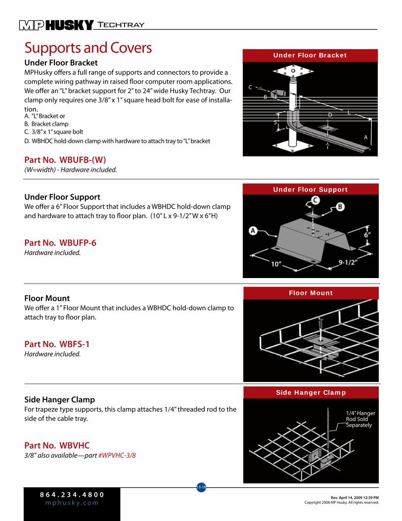
8 6 4 . 2 3 4 . 4 8 0 0m p h u s k y . c o m
Rev. April 14, 2009 12:39 PMCopyright 2008 MP Husky. All rights reserved.
Techtray
13-18
Supports and CoversUnder Floor BracketMPHusky offers a full range of supports and connectors to provide a complete wiring pathway in raised floor computer room applications.We offer an “L” bracket support for 2” to 24” wide Husky Techtray. Our clamp only requires one 3/8” x 1” square head bolt for ease of installa-tion.A. “L” Bracket orB. Bracket clampC. 3/8” x 1” square boltD. WBHDC hold-down clamp with hardware to attach tray to “L” bracket
Part No. WBUFB-(W)(W=width) - Hardware included.
Under Floor SupportWe offer a 6” Floor Support that includes a WBHDC hold-down clamp and hardware to attach tray to floor plan. (10” L x 9-1/2” W x 6”H)
Part No. WBUFP-6Hardware included.
Floor MountWe offer a 1” Floor Mount that includes a WBHDC hold-down clamp to attach tray to floor plan.
Part No. WBFS-1Hardware included.
Side Hanger ClampFor trapeze type supports, this clamp attaches 1/4” threaded rod to the side of the cable tray.
Part No. WBVHC3/8” also available—part #WPVHC-3/8
Under Floor Bracket
A
B
C
D
Under Floor Support
Floor Mount
Side Hanger Clamp
1/4” HangerRod SoldSeparately
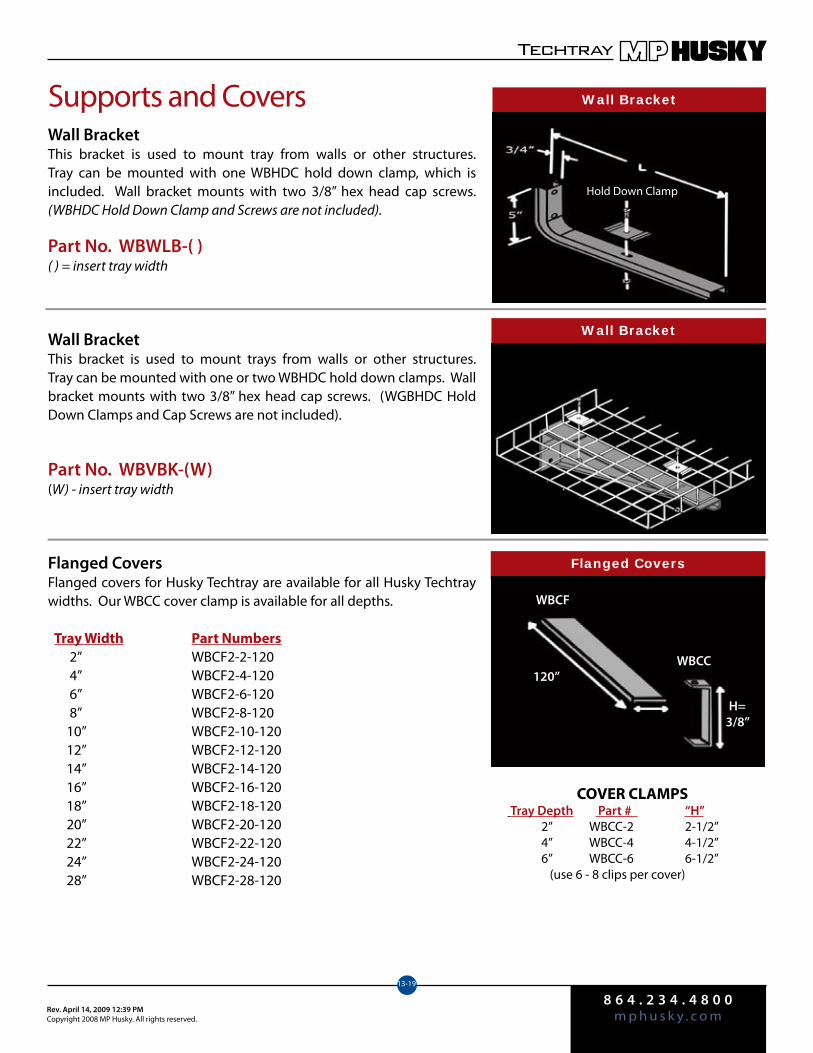
8 6 4 . 2 3 4 . 4 8 0 0m p h u s k y . c o mRev. April 14, 2009 12:39 PM
Copyright 2008 MP Husky. All rights reserved.
Techtray
13-19
Supports and CoversWall BracketThis bracket is used to mount tray from walls or other structures. Tray can be mounted with one WBHDC hold down clamp, which is included. Wall bracket mounts with two 3/8” hex head cap screws. (WBHDC Hold Down Clamp and Screws are not included).
Part No. WBWLB-( )( ) = insert tray width
Wall BracketThis bracket is used to mount trays from walls or other structures. Tray can be mounted with one or two WBHDC hold down clamps. Wall bracket mounts with two 3/8” hex head cap screws. (WGBHDC Hold Down Clamps and Cap Screws are not included).
Part No. WBVBK-(W)(W) - insert tray width
Flanged CoversFlanged covers for Husky Techtray are available for all Husky Techtray widths. Our WBCC cover clamp is available for all depths.
Tray Width Part Numbers 2” WBCF2-2-120 4” WBCF2-4-120 6” WBCF2-6-120 8” WBCF2-8-120 10” WBCF2-10-120 12” WBCF2-12-120 14” WBCF2-14-120 16” WBCF2-16-120 18” WBCF2-18-120 20” WBCF2-20-120 22” WBCF2-22-120 24” WBCF2-24-120 28” WBCF2-28-120
Wall Bracket
Hold Down Clamp
Wall Bracket
Flanged Covers
WBCF
WBCC120”
H=3/8”
COVER CLAMPS Tray Depth Part # “H” 2” WBCC-2 2-1/2” 4” WBCC-4 4-1/2” 6” WBCC-6 6-1/2” (use 6 - 8 clips per cover)
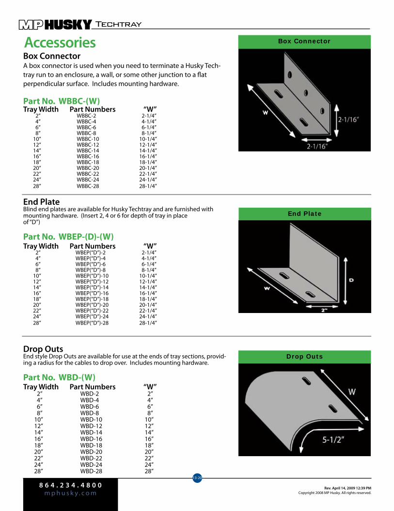
8 6 4 . 2 3 4 . 4 8 0 0m p h u s k y . c o m
Rev. April 14, 2009 12:39 PMCopyright 2008 MP Husky. All rights reserved.
Techtray
13-20
AccessoriesBox ConnectorA box connector is used when you need to terminate a Husky Tech-tray run to an enclosure, a wall, or some other junction to a flat perpendicular surface. Includes mounting hardware.
Part No. WBBC-(W)Tray Width Part Numbers “W” 2” WBBC-2 2-1/4” 4” WBBC-4 4-1/4” 6” WBBC-6 6-1/4” 8” WBBC-8 8-1/4” 10” WBBC-10 10-1/4” 12” WBBC-12 12-1/4” 14” WBBC-14 14-1/4” 16” WBBC-16 16-1/4” 18” WBBC-18 18-1/4” 20” WBBC-20 20-1/4” 22” WBBC-22 22-1/4” 24” WBBC-24 24-1/4” 28” WBBC-28 28-1/4”
End PlateBlind end plates are available for Husky Techtray and are furnished with mounting hardware. (Insert 2, 4 or 6 for depth of tray in place of “D”)
Part No. WBEP-(D)-(W)Tray Width Part Numbers “W” 2” WBEP(“D”)-2 2-1/4” 4” WBEP(“D”)-4 4-1/4” 6” WBEP(“D”)-6 6-1/4” 8” WBEP(“D”)-8 8-1/4” 10” WBEP(“D”)-10 10-1/4” 12” WBEP(“D”)-12 12-1/4” 14” WBEP(“D”)-14 14-1/4” 16” WBEP(“D”)-16 16-1/4” 18” WBEP(“D”)-18 18-1/4” 20” WBEP(“D”)-20 20-1/4” 22” WBEP(“D”)-22 22-1/4” 24” WBEP(“D”)-24 24-1/4” 28” WBEP(“D”)-28 28-1/4”
Drop OutsEnd style Drop Outs are available for use at the ends of tray sections, provid-ing a radius for the cables to drop over. Includes mounting hardware.
Part No. WBD-(W)Tray Width Part Numbers “W” 2” WBD-2 2” 4” WBD-4 4” 6” WBD-6 6” 8” WBD-8 8” 10” WBD-10 10” 12” WBD-12 12” 14” WBD-14 14” 16” WBD-16 16” 18” WBD-18 18” 20” WBD-20 20” 22” WBD-22 22” 24” WBD-24 24” 28” WBD-28 28”
Box Connector
End Plate
Drop Outs
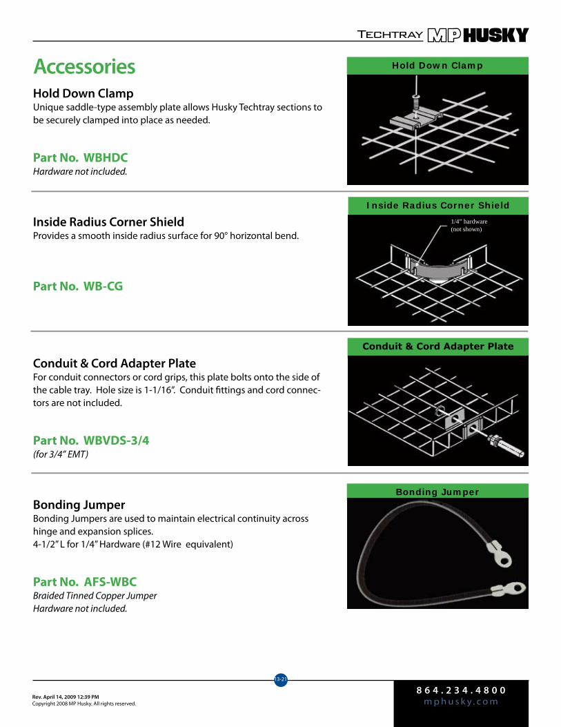
8 6 4 . 2 3 4 . 4 8 0 0m p h u s k y . c o mRev. April 14, 2009 12:39 PM
Copyright 2008 MP Husky. All rights reserved.
Techtray
13-21
AccessoriesHold Down ClampUnique saddle-type assembly plate allows Husky Techtray sections to be securely clamped into place as needed.
Part No. WBHDCHardware not included.
Inside Radius Corner ShieldProvides a smooth inside radius surface for 90° horizontal bend.
Part No. WB-CG
Conduit & Cord Adapter PlateFor conduit connectors or cord grips, this plate bolts onto the side of the cable tray. Hole size is 1-1/16”. Conduit fittings and cord connec-tors are not included.
Part No. WBVDS-3/4(for 3/4” EMT)
Bonding JumperBonding Jumpers are used to maintain electrical continuity across hinge and expansion splices.4-1/2” L for 1/4” Hardware (#12 Wire equivalent)
Part No. AFS-WBCBraided Tinned Copper JumperHardware not included.
Hold Down Clamp
Inside Radius Corner Shield
Conduit & Cord Adapter Plate
Bonding Jumper
1/4” hardware (not shown)

8 6 4 . 2 3 4 . 4 8 0 0m p h u s k y . c o m
Rev. April 14, 2009 12:39 PMCopyright 2008 MP Husky. All rights reserved.
Techtray
13-22
AccessoriesWall Penetration SleeveMPHusky’s Wall Penetration Sleeve is used when tray has to pass through a wall. Includes 24” long pan, cover and two wall mounting flanges. Clamps included to fasten the wire basket to the pan.
Part No. PWPS-(W)-WB2 (D)W = widthD = depth
Barrier StripsBarrier strips are available for Husky Techtray when cable separation is necessary. These separators come in 2” through 6” heights and are slotted at regular intervals for ease of installation without field drilling. Each barrier strip is furnished with the hardware necessary to install in the Husky Techtray. The standard length is 10ft. for straight sections and 4ft. for horizontal sections.
Our CSS Separator Splice (sold separately) is applied to ensure a smooth transition between barrier strips.
Part No. CSS
GroundingMPHusky recommends using a split-bolt for connecting external ground wires to our Husky Techtray. We offer two types for you to choose from. WB-GB divides the copper wire from the basket steel wire. The WB-29 pulls the bare ground wire against the steel basket wire.
Wall Penetration Sleeve
Barrier Strips
CSS Separator Splice For Straight Lengths Height Mill-Galvanized 2” S2S-120-WB 4” S4S-120-WB 6” S6S-120-WB For Horizontal Bends Height Mill-Galvanized 2” S2S-HA-WB 4” S4S-HA-WB 6” S6S-HA-WB
Grounding
Part No. WB-GBFor #8 - #6 wire, 100A - 200A (tin plated)
Part No. WB-29For #10 - #6 wire (non-plated)
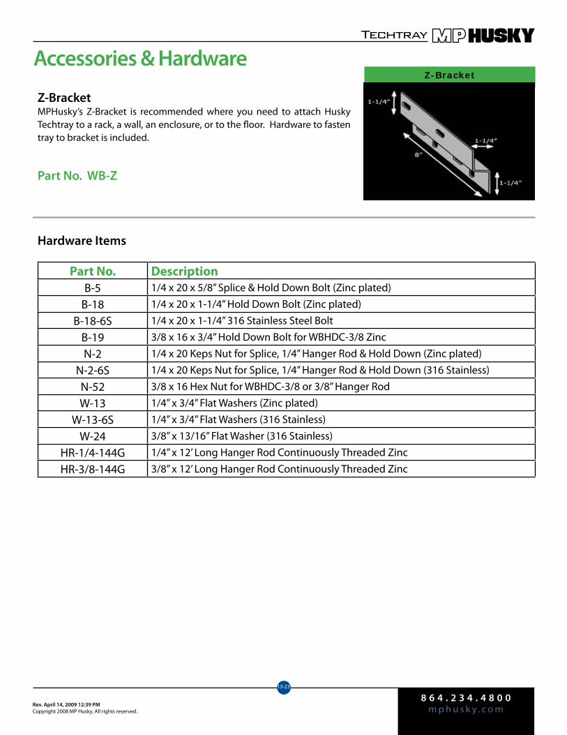
8 6 4 . 2 3 4 . 4 8 0 0m p h u s k y . c o mRev. April 14, 2009 12:39 PM
Copyright 2008 MP Husky. All rights reserved.
Techtray
13-23
Accessories & HardwareZ-Bracket
Z-BracketMPHusky’s Z-Bracket is recommended where you need to attach Husky Techtray to a rack, a wall, an enclosure, or to the floor. Hardware to fasten tray to bracket is included.
Part No. WB-Z
Hardware Items
Part No. DescriptionB-5 1/4 x 20 x 5/8” Splice & Hold Down Bolt (Zinc plated)
B-18 1/4 x 20 x 1-1/4” Hold Down Bolt (Zinc plated)
B-18-6S 1/4 x 20 x 1-1/4” 316 Stainless Steel Bolt
B-19 3/8 x 16 x 3/4” Hold Down Bolt for WBHDC-3/8 Zinc
N-2 1/4 x 20 Keps Nut for Splice, 1/4” Hanger Rod & Hold Down (Zinc plated)
N-2-6S 1/4 x 20 Keps Nut for Splice, 1/4” Hanger Rod & Hold Down (316 Stainless)
N-52 3/8 x 16 Hex Nut for WBHDC-3/8 or 3/8” Hanger Rod
W-13 1/4” x 3/4” Flat Washers (Zinc plated)
W-13-6S 1/4” x 3/4” Flat Washers (316 Stainless)
W-24 3/8” x 13/16” Flat Washer (316 Stainless)
HR-1/4-144G 1/4” x 12’ Long Hanger Rod Continuously Threaded Zinc
HR-3/8-144G 3/8” x 12’ Long Hanger Rod Continuously Threaded Zinc
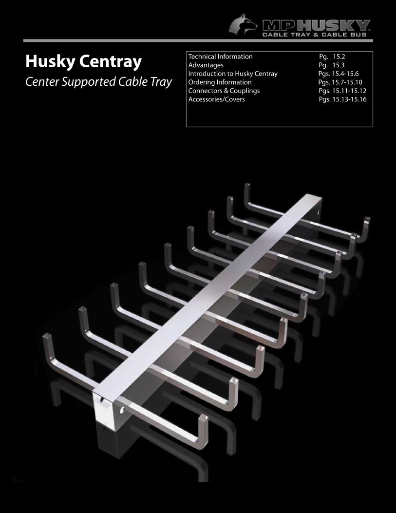
14.1
Husky CentrayCenter Supported Cable Tray
Technical Information Pg. 15.2Advantages Pg. 15.3Introduction to Husky Centray Pgs. 15.4-15.6Ordering Information Pgs. 15.7-15.10Connectors & Couplings Pgs. 15.11-15.12Accessories/Covers Pgs. 15.13-15.16
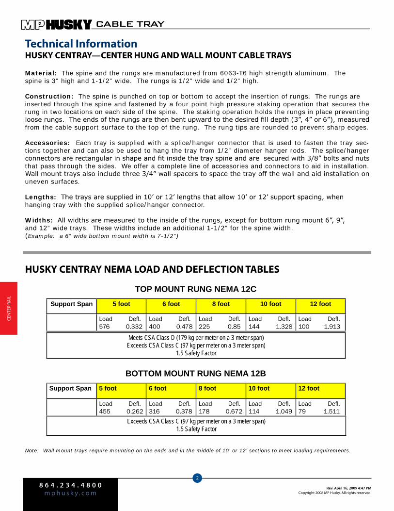
8 6 4 . 2 3 4 . 4 8 0 0m p h u s k y . c o m
Rev. April 16, 2009 4:47 PMCopyright 2008 MP Husky. All rights reserved.
CABLE TRAY
2
Cen
Ter
rAIl
HUSKY CENTRAY NEMA LOAD AND DEFLECTION TABLES
Note: Wall mount trays require mounting on the ends and in the middle of 10’ or 12’ sections to meet loading requirements.
Support Span 5 foot 6 foot 8 foot 10 foot 12 foot
Load Defl.576 0.332
Load Defl.400 0.478
Load Defl.225 0.85
Load Defl.144 1.328
Load Defl.100 1.913
TOP MOUNT RUNG NEMA 12C
BOTTOM MOUNT RUNG NEMA 12BSupport Span 5 foot 6 foot 8 foot 10 foot 12 foot
Load Defl.455 0.262
Load Defl.316 0.378
Load Defl.178 0.672
Load Defl.114 1.049
Load Defl.79 1.511
Exceeds CSA Class C (97 kg per meter on a 3 meter span)1.5 Safety Factor
Meets CSA Class D (179 kg per meter on a 3 meter span)Exceeds CSA Class C (97 kg per meter on a 3 meter span)
1.5 Safety Factor
Technical InformationHUSKY CENTRAY—CENTER HUNG AND WALL MOUNT CABLE TRAYS
Material: The spine and the rungs are manufactured from 6063-T6 high strength aluminum. The spine is 3” high and 1-1/2” wide. The rungs is 1/2” wide and 1/2” high.
Construction: The spine is punched on top or bottom to accept the insertion of rungs. The rungs are inserted through the spine and fastened by a four point high pressure staking operation that secures the rung in two locations on each side of the spine. The staking operation holds the rungs in place preventing loose rungs. The ends of the rungs are then bent upward to the desired fill depth (3”, 4” or 6”), measured from the cable support surface to the top of the rung. The rung tips are rounded to prevent sharp edges.
Accessories: Each tray is supplied with a splice/hanger connector that is used to fasten the tray sec-tions together and can also be used to hang the tray from 1/2” diameter hanger rods. The splice/hanger connectors are rectangular in shape and fit inside the tray spine and are secured with 3/8” bolts and nuts that pass through the sides. We offer a complete line of accessories and connectors to aid in installation. Wall mount trays also include three 3/4” wall spacers to space the tray off the wall and aid installation on uneven surfaces.
Lengths: The trays are supplied in 10’ or 12’ lengths that allow 10’ or 12’ support spacing, when hanging tray with the supplied splice/hanger connector.
Widths: All widths are measured to the inside of the rungs, except for bottom rung mount 6”, 9”,and 12” wide trays. These widths include an additional 1-1/2” for the spine width.(Example: a 6” wide bottom mount width is 7-1/2”)
8 6 4 . 2 3 4 . 4 8 0 0m p h u s k y . c o mRev. April 16, 2009 4:47 PM
Copyright 2008 MP Husky. All rights reserved.
CABLE TRAY
3
CenTer rA
Il
Cable tray sections are securely joined by only two bolts or an EZ-Clip, which greatly ♦reduces installation costs.
Reduced cable installation headaches, as the cable tray is easily accessed from the ♦side. Cable loading, inspection and retrofit is simplified.
For lightweight reliability, Husky Centray systems are made from corrosion-resistant, ♦high-strength aluminum.
EZ-Clip speeds installation time and minimizes hardware. ♦
Over 50% less support hardware than standard cable trays. ♦
Standard cable tray fittings are no longer needed for elbows, tees and crosses. ♦
For safety and reliability, rungs are firmly attached by the four-point staking method. ♦
All rungs have smooth, chamfered ends. ♦
Top and bottom rung center-supported cable tray and wall rack are CSA certified. (LR 107538)
Top rung Husky Centray meets NEMA Load Class 12C and bottom rung Husky Centray meets NEMA Load Class 12B, in accordance with NEMA Standard VE-1.
Husky Centray systems are classified by Underwriters Laboratories as a grounding means.
Advantages of Husky Centray Support Systems
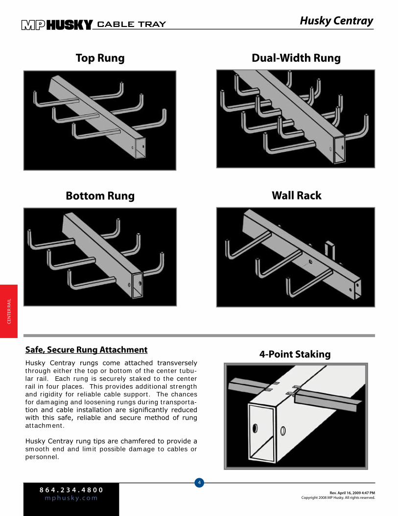
8 6 4 . 2 3 4 . 4 8 0 0m p h u s k y . c o m
Rev. April 16, 2009 4:47 PMCopyright 2008 MP Husky. All rights reserved.
CABLE TRAY
4
Cen
Ter
rAIl
Husky Centray
Top Rung Dual-Width Rung
Bottom Rung Wall Rack
Safe, Secure Rung AttachmentHusky Centray rungs come attached transversely through either the top or bottom of the center tubu-lar rail. Each rung is securely staked to the center rail in four places. This provides additional strength and rigidity for reliable cable support. The chances for damaging and loosening rungs during transporta-tion and cable installation are significantly reduced with this safe, reliable and secure method of rung attachment.
Husky Centray rung tips are chamfered to provide a smooth end and limit possible damage to cables or personnel.
4-Point Staking
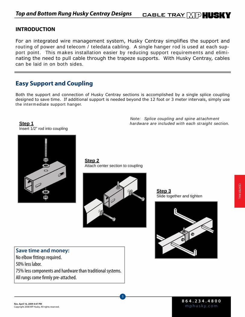
8 6 4 . 2 3 4 . 4 8 0 0m p h u s k y . c o mRev. April 16, 2009 4:47 PM
Copyright 2008 MP Husky. All rights reserved.
CABLE TRAY
5
CenTer rA
Il
INTRODUCTION
For an integrated wire management system, Husky Centray simplifies the support and routing of power and telecom / teledata cabling. A single hanger rod is used at each sup-port point. This makes installation easier by reducing support requirements and elimi-nating the need to pull cable through the trapeze supports. With Husky Centray, cables can be laid in on both sides.
Easy Support and Coupling
Both the support and connection of Husky Centray sections is accomplished by a single splice coupling designed to save time. If additional support is needed beyond the 12 foot or 3 meter intervals, simply use the intermediate support hanger.
Note: Splice coupling and spine attachment hardware are included with each straight section.Step 1
Insert 1/2” rod into coupling
Step 2Attach center section to coupling
Step 3Slide together and tighten
Save time and money:No elbow fittings required.50% less labor.75% less components and hardware than traditional systems.All rungs come firmly pre-attached.
Top and Bottom Rung Husky Centray Designs
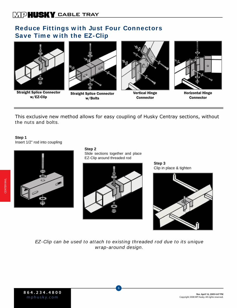
8 6 4 . 2 3 4 . 4 8 0 0m p h u s k y . c o m
Rev. April 16, 2009 4:47 PMCopyright 2008 MP Husky. All rights reserved.
CABLE TRAY
6
Cen
Ter
rAIl
Reduce Fittings with Just Four ConnectorsSave Time with the EZ-Clip
Straight Splice Connector w/EZ-Clip
Straight Splice Connector w/Bolts
Vertical HingeConnector
Horizontal HingeConnector
Step 1Insert 1/2” rod into coupling
Step 2Slide sections together and place EZ-Clip around threaded rod
Step 3Clip in place & tighten
This exclusive new method allows for easy coupling of Husky Centray sections, without the nuts and bolts.
EZ-Clip can be used to attach to existing threaded rod due to its unique wrap-around design.
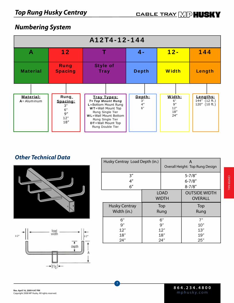
8 6 4 . 2 3 4 . 4 8 0 0m p h u s k y . c o mRev. April 16, 2009 4:47 PM
Copyright 2008 MP Husky. All rights reserved.
CABLE TRAY
7
CenTer rA
Il
Top Rung Husky Centray
Numbering System
Other Technical Data
A 12 T 4- 12- 144
MaterialRung
SpacingStyle of
Tray Depth Width Length
A12T4-12-144
Material:A=Aluminum
Rung Spacing:
3”6”9”12”18”
Tray Types:T=Top Mount Rung
L=Bottom Mount RungWT=Wall Mount Top
Rung Single TierWL=Wall Mount Bottom
Rung Single TierDT=Wall Mount Top Rung Double Tier
Depth:3”4”6”
Width:6”9”12”18”24”
Lengths:144” (12 ft.)120” (10 ft.)
Husky Centray load Depth (in.) AOverall Height: Top rung Design
3”4”6”
5-7/8”6-7/8”8-7/8”
Husky CentrayWidth (in.)
Toprung
Toprung
6”9”
12”18”24”
6”9”
12”18”24”
7”10”13”19”25”
lOAD WIDTH
OUTSIDe WIDTH OVerAll
1/2”1/2”

8 6 4 . 2 3 4 . 4 8 0 0m p h u s k y . c o m
Rev. April 16, 2009 4:47 PMCopyright 2008 MP Husky. All rights reserved.
CABLE TRAY
8
Cen
Ter
rAIl
Numbering System
Other Technical Data
A 12 L 4- 12- 144
MaterialRung
SpacingStyle
of Tray Depth Width Length
A12L4-12-144
Material:A=Aluminum
Rung Spacing:
3”6”9”12”18”
Tray Types:T=Top Mount RungL=Bottom Mount
RungWT=Wall Mount Top
Rung Single TierWL=Wall Mount Bottom
Rung Single TierDT=Wall Mount Top Rung Double Tier
Depth:3”4”6”
Width:6”9”12”18”24”
Lengths:144” (12 ft.)120” (10 ft.)
Husky Centray load Depth (in.)
AOverall Height: Bottom rung Design
3”4”6”
3-1/8”4-1/8”6-1/8”
lOAD WIDTH
OUTSIDe WIDTH OVerAll
1/2” 1/2”
Bottom Rung Husky Centray
Husky CentrayWidth (in.)
Bottomrung
Bottomrung
6”9”
12”18”24”
7-1/2”10-1/2”13-1/2”
18”24”
8-1/2”11-1/2”14-1/2”
19”25”
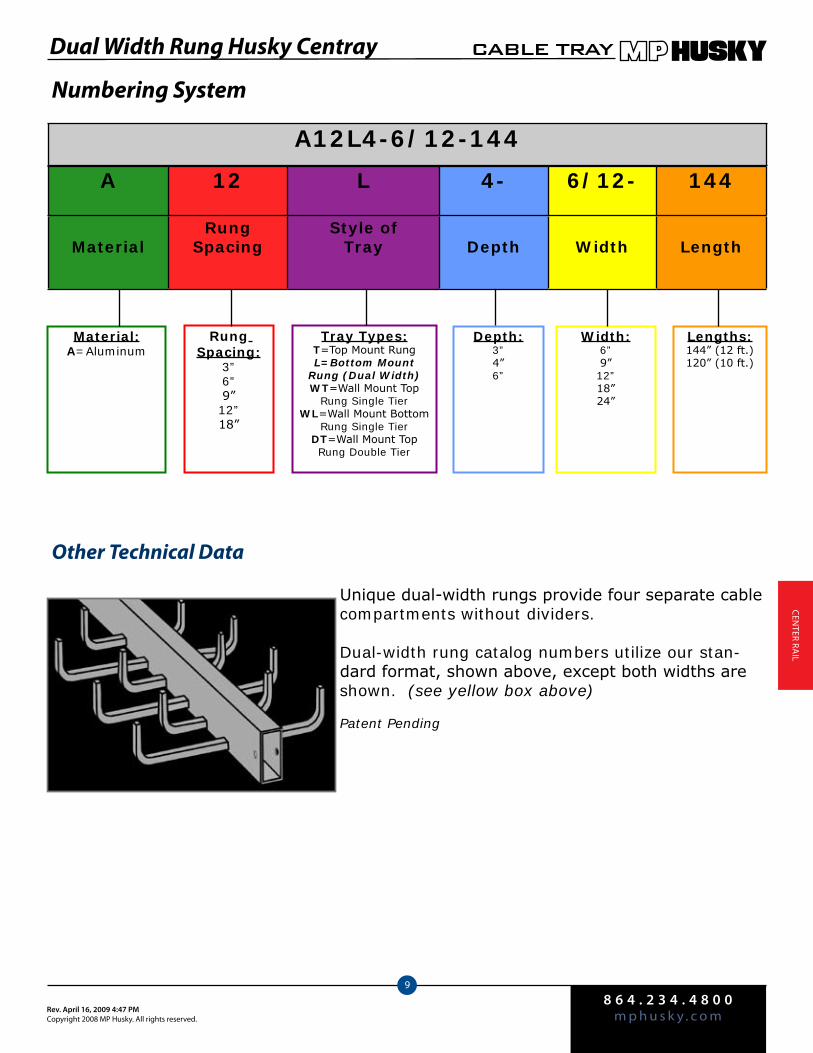
8 6 4 . 2 3 4 . 4 8 0 0m p h u s k y . c o mRev. April 16, 2009 4:47 PM
Copyright 2008 MP Husky. All rights reserved.
CABLE TRAY
9
CenTer rA
Il
Numbering System
Other Technical Data
Unique dual-width rungs provide four separate cable compartments without dividers.
Dual-width rung catalog numbers utilize our stan-dard format, shown above, except both widths are shown. (see yellow box above)
Patent Pending
A 12 L 4- 6/12- 144
MaterialRung
SpacingStyle of
Tray Depth Width Length
A12L4-6/12-144
Material:A=Aluminum
Rung Spacing:
3”6”9”12”18”
Tray Types:T=Top Mount RungL=Bottom Mount
Rung (Dual Width)WT=Wall Mount Top
Rung Single TierWL=Wall Mount Bottom
Rung Single TierDT=Wall Mount Top Rung Double Tier
Depth:3”4”6”
Width:6”9”12”18”24”
Lengths:144” (12 ft.)120” (10 ft.)
Dual Width Rung Husky Centray
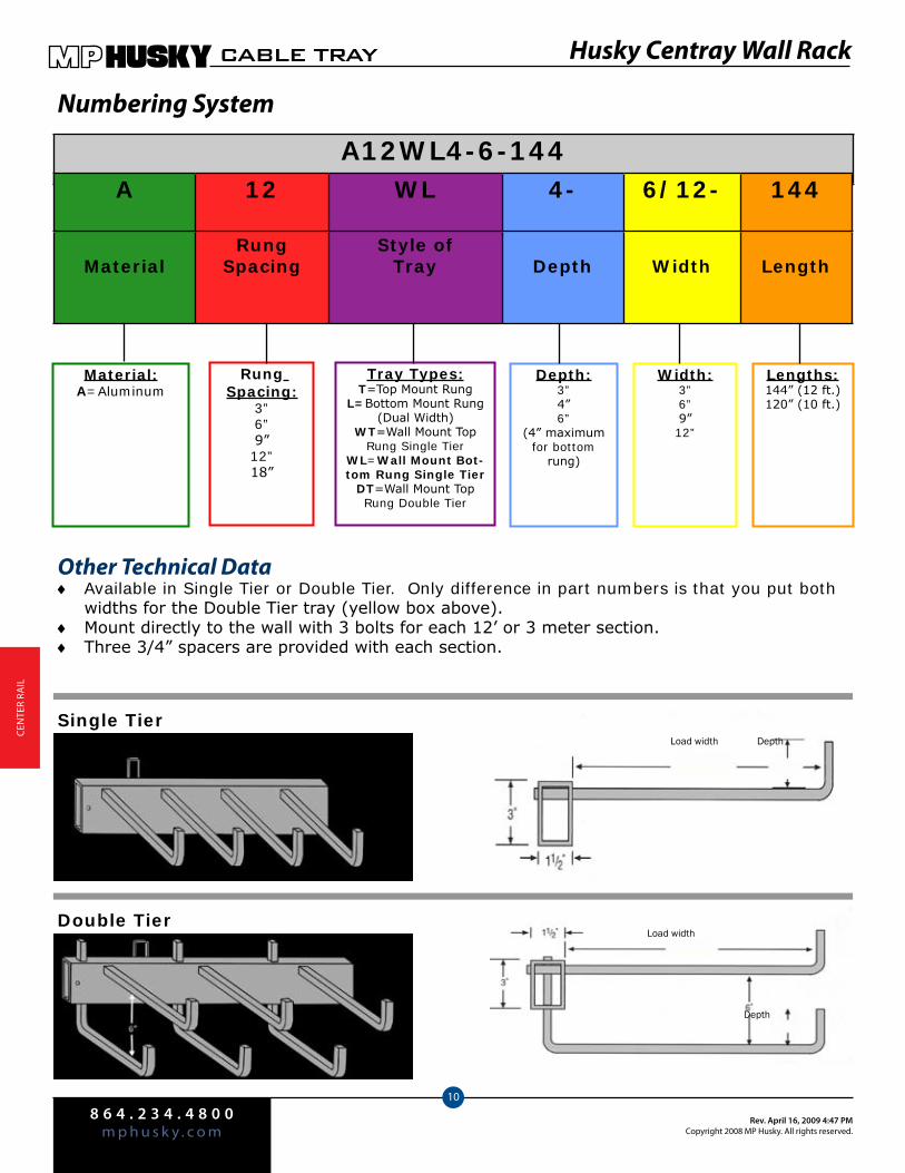
8 6 4 . 2 3 4 . 4 8 0 0m p h u s k y . c o m
Rev. April 16, 2009 4:47 PMCopyright 2008 MP Husky. All rights reserved.
CABLE TRAY
10
Cen
Ter
rAIl
Numbering System
Other Technical DataAvailable in Single Tier or Double Tier. Only difference in part numbers is that you put both ♦widths for the Double Tier tray (yellow box above).Mount directly to the wall with 3 bolts for each 12’ or 3 meter section. ♦Three 3/4” spacers are provided with each section. ♦
A12WL4-6-144
Material:A=Aluminum
Rung Spacing:
3”6”9”12”18”
Tray Types:T=Top Mount Rung
L=Bottom Mount Rung (Dual Width)
WT=Wall Mount Top Rung Single Tier
WL=Wall Mount Bot-tom Rung Single Tier
DT=Wall Mount Top Rung Double Tier
Depth:3”4”6”
(4” maximum for bottom
rung)
Width:3”6”9”12”
Lengths:144” (12 ft.)120” (10 ft.)
Load width Depth
Load width
Depth
Single Tier
Double Tier
Husky Centray Wall Rack
A 12 WL 4- 6/12- 144
MaterialRung
SpacingStyle of
Tray Depth Width Length
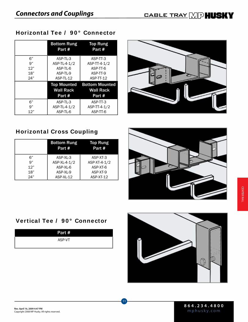
8 6 4 . 2 3 4 . 4 8 0 0m p h u s k y . c o mRev. April 16, 2009 4:47 PM
Copyright 2008 MP Husky. All rights reserved.
CABLE TRAY
11
CenTer rA
Il
Horizontal Tee / 90° Connector
Tray Width
Bottom RungPart #
Top RungPart #
6”9”
12”18”24”
ASP-TL-3ASP-TL-4-1/2
ASP-TL-6ASP-TL-9
ASP-TL-12
ASP-TT-3ASP-TT-4-1/2
ASP-TT-6ASP-TT-9
ASP-TT-12Tray
WidthTop Mounted
Wall Rack Part #
Bottom Mounted Wall Rack
Part #6”9”
12”
ASP-TL-3ASP-TL-4-1/2
ASP-TL-6
ASP-TT-3ASP-TT-4-1/2
ASP-TT-6
Tray Width
Bottom RungPart #
Top RungPart #
6”9”
12”18”24”
ASP-XL-3ASP-XL-4-1/2
ASP-XL-6ASP-XL-9
ASP-XL-12
ASP-XT-3ASP-XT-4-1/2
ASP-XT-6ASP-XT-9
ASP-XT-12
Part #ASP-VT
Horizontal Cross Coupling
Vertical Tee / 90° Connector
Connectors and Couplings
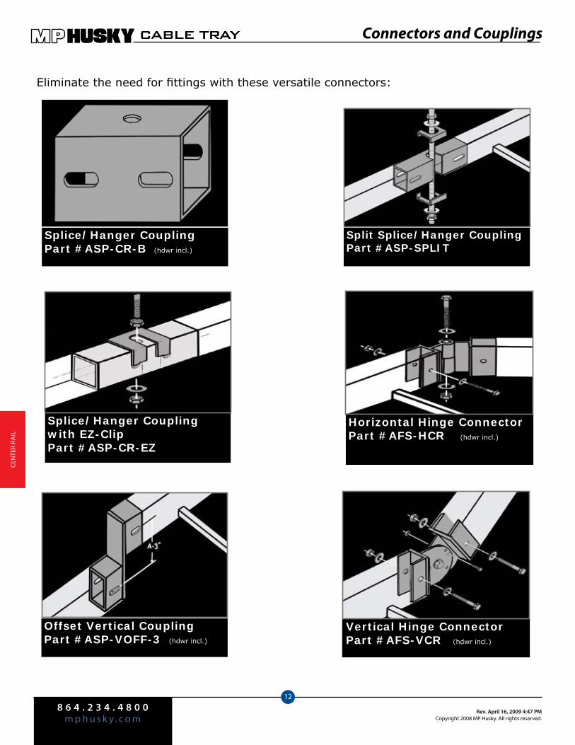
8 6 4 . 2 3 4 . 4 8 0 0m p h u s k y . c o m
Rev. April 16, 2009 4:47 PMCopyright 2008 MP Husky. All rights reserved.
CABLE TRAY
12
Cen
Ter
rAIl
Eliminate the need for fittings with these versatile connectors:
Splice/Hanger CouplingPart #ASP-CR-B (hdwr incl.)
Splice/Hanger Coupling with EZ-ClipPart #ASP-CR-EZ
Offset Vertical CouplingPart #ASP-VOFF-3 (hdwr incl.)
Split Splice/Hanger CouplingPart #ASP-SPLIT
Horizontal Hinge ConnectorPart #AFS-HCR (hdwr incl.)
Vertical Hinge ConnectorPart #AFS-VCR (hdwr incl.)
Connectors and Couplings
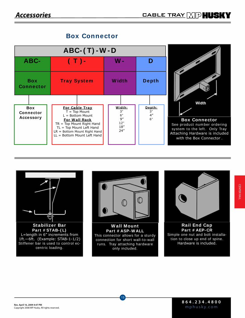
8 6 4 . 2 3 4 . 4 8 0 0m p h u s k y . c o mRev. April 16, 2009 4:47 PM
Copyright 2008 MP Husky. All rights reserved.
CABLE TRAY
13
CenTer rA
Il
Box Connector
ABC-(T)-W-D
BoxConnector Accessory
Width:3”6”9”12”18”24”
Depth:3”4”6” Box Connector
See product number ordering system to the left. Only Tray
Attaching Hardware is included with the Box Connector..
Stabilizer BarPart #STAB-(L)
L=length in 6” increments from 1ft.—6ft. (Example: STAB-1-1/2)Stiffener bar is used to control ec-
centric loading.
Hanger rod nut
Stabilizer Bar
Tray
Wall MountPart #ASP-WALL
This connector allows for a sturdy connection for short wall-to-wall runs. Tray attaching hardware
only included.
Rail End CapPart #AEP-CR
Simple one nut and bolt installa-tion to close up end of spine.
Hardware is included.
Accessories
ABC- ( T )- W- D
Box Connector
Tray System Width Depth
For Cable TrayT = Top Mount
L = Bottom MountFor Wall Rack
TR = Top Mount Right HandTL = Top Mount Left Hand
LR = Bottom Mount Right HandLL = Bottom Mount Left Hand
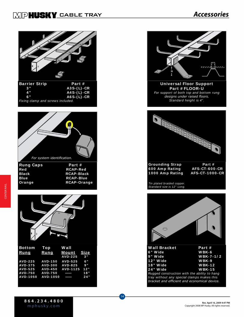
8 6 4 . 2 3 4 . 4 8 0 0m p h u s k y . c o m
Rev. April 16, 2009 4:47 PMCopyright 2008 MP Husky. All rights reserved.
CABLE TRAY
14
Cen
Ter
rAIl
Barrier Strip Part # 3” A3S-(L)-CR 4” A4S-(L)-CR 6” A6S-(L)-CRFixing clamp and screws included.
Rung Caps Part #Red RCAP-RedBlack RCAP-BlackBlue RCAP-BlueOrange RCAP-Orange
Bottom Top WallRung Rung Mount Size AVD-225 3” AVD-225 AVD-150 AVD-525 6” AVD-375 AVD-300 AVD-825 9”AVD-525 AVD-450 AVD-1125 12”AVD-750 AVD-750 —— 18”AVD-1050 AVD-1050 —— 24”
Universal Floor SupportPart #FLOOR-U
For support of both top and bottom rung designs under raised floors.
Standard height is 4”.
Wall Bracket Part #6” Wide WBK-69” Wide WBK-7-1/212” Wide WBK-918” Wide WBK-1224” Wide WBK-15Rugged construction with the ability to hang tray without any special clamps makes this bracket and efficient and economical device.
Grounding Strap Part #600 Amp Rating AFS-CT-600-CR1000 Amp Rating AFS-CT-1000-CR
Tin plated braided copper. Standard size is 12” Long.
Accessories
For system identification.
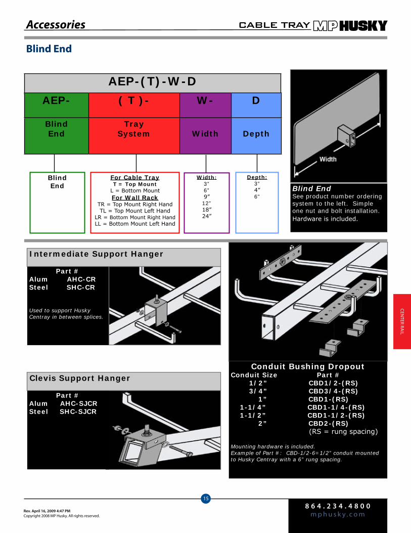
8 6 4 . 2 3 4 . 4 8 0 0m p h u s k y . c o mRev. April 16, 2009 4:47 PM
Copyright 2008 MP Husky. All rights reserved.
CABLE TRAY
15
CenTer rA
Il
Part #Alum AHC-CRSteel SHC-CR
Used to support Husky Centray in between splices.
Part #Alum AHC-SJCRSteel SHC-SJCR
AEP-(T)-W-D
BlindEnd
For Cable TrayT = Top Mount
L = Bottom MountFor Wall Rack
TR = Top Mount Right HandTL = Top Mount Left Hand
LR = Bottom Mount Right HandLL = Bottom Mount Left Hand
Width:3”6”9”12”18”24”
Depth:3”4”6”
Blind End
Blind EndSee product number ordering system to the left. Simple one nut and bolt installation. Hardware is included.
Conduit Bushing DropoutConduit Size Part # 1/2” CBD1/2-(RS) 3/4” CBD3/4-(RS) 1” CBD1-(RS) 1-1/4” CBD1-1/4-(RS) 1-1/2” CBD1-1/2-(RS) 2” CBD2-(RS) (RS = rung spacing)
Mounting hardware is included.Example of Part #: CBD-1/2-6=1/2” conduit mounted to Husky Centray with a 6” rung spacing.
Intermediate Support Hanger
Clevis Support Hanger
Accessories
AEP- ( T )- W- D
BlindEnd
Tray System Width Depth
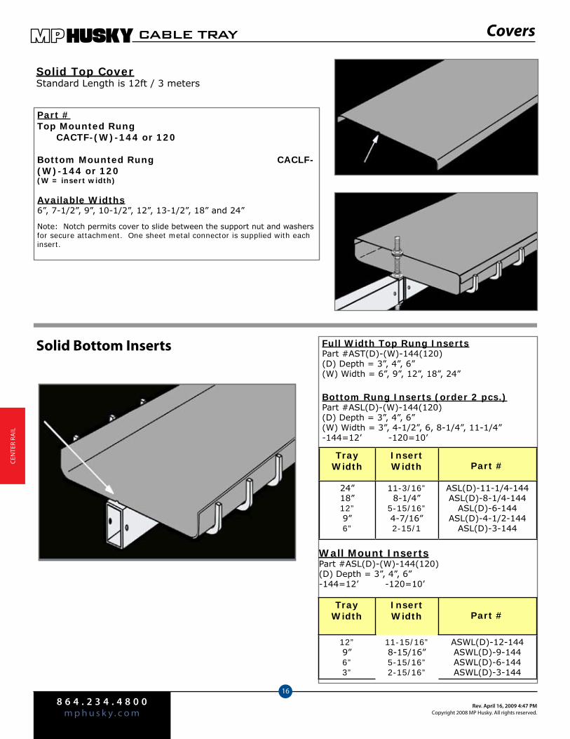
8 6 4 . 2 3 4 . 4 8 0 0m p h u s k y . c o m
Rev. April 16, 2009 4:47 PMCopyright 2008 MP Husky. All rights reserved.
CABLE TRAY
16
Cen
Ter
rAIl
Covers
Solid Top CoverStandard Length is 12ft / 3 meters
Part #Top Mounted Rung CACTF-(W)-144 or 120
Bottom Mounted Rung CACLF-(W)-144 or 120(W = insert width)
Available Widths6”, 7-1/2”, 9”, 10-1/2”, 12”, 13-1/2”, 18” and 24”
Note: Notch permits cover to slide between the support nut and washers for secure attachment. One sheet metal connector is supplied with each insert.
Solid Bottom Inserts Full Width Top Rung InsertsPart #AST(D)-(W)-144(120)(D) Depth = 3”, 4”, 6”(W) Width = 6”, 9”, 12”, 18”, 24”
Bottom Rung Inserts (order 2 pcs.)Part #ASL(D)-(W)-144(120)(D) Depth = 3”, 4”, 6”(W) Width = 3”, 4-1/2”, 6, 8-1/4”, 11-1/4”-144=12’ -120=10’
Tray Width
InsertWidth Part #
24”18”12”9”6”
11-3/16”8-1/4”
5-15/16”4-7/16”2-15/1
ASL(D)-11-1/4-144ASL(D)-8-1/4-144
ASL(D)-6-144ASL(D)-4-1/2-144
ASL(D)-3-144
Tray Width
InsertWidth Part #
12”9”6”3”
11-15/16”8-15/16”5-15/16”2-15/16”
ASWL(D)-12-144ASWL(D)-9-144ASWL(D)-6-144ASWL(D)-3-144
Wall Mount InsertsPart #ASL(D)-(W)-144(120)(D) Depth = 3”, 4”, 6”-144=12’ -120=10’

15.1
HUSKY FIBERGLASSCable Tray
Technical Information Pgs. 16.2—16.6 Installation Guide Pg. 16.7Corrosion Guide Pgs. 16.8—16.116” Husky Fiberglass Tray Pgs. 16.12—16.214” Husky Fiberglass Tray Pgs. 16.22—16.303” Husky Fiberglass Tray Pgs. 16.31—16.36Channel Husky Fiberglass Tray Pgs. 16.37—16.41Specifications Pg. 16.42Fittings & Accessories Pgs. 16.43—16.46Strut Section Pgs. 16.47—16.55

8 6 4 . 2 3 4 . 4 8 0 0m p h u s k y . c o m
Rev. April 16, 2009 4:50 PMCopyright 2008 MP Husky. All rights reserved.
CABLE TRAY
2
FIbe
rGlA
SS
For more than 30 years, MPHusky’s Fiberglass Cable Tray systems have been tested and proven in the harsh environment of the offshore oil and gas industry. Our tray has stood up to the test of being exposed to the corrosive conditions inherent in petroleum products, plus the daily punishment of exposure to wind, weather and salt water. MPHusky Fiberglass Cable Tray gives you the load capacity of steel, plus the inher-ent characteristics afforded by our Pultrusion Technology: non-conductive, non-magnetic and corrosion-resistant. Although light in weight, the strength to weight ratio surpasses that of equivalent steel products. Husky Fiberglass Cable Tray will not rust, nor does it ever require painting. It is available in both polyester and vinylester resin systems, manufactured to meet ASTM e-84, Class 1 Flame rating and self-extinguishing requirements of ASTM D-635. Husky’s Fiberglass Cable Tray comes in gray or blue (polyester resin) and beige (vinylester resin) but is available in custom colors upon request.
Load Data
Effect of TemperatureStrength properties of reinforced plastics are reduced when continuously exposed to elevated temperatures. Working loads shall be reduced based on the following:
NEMA Standard 8-10-1986. If unusual temperature conditions exist, please consult the manufacturer.
Temperature in Degrees F
Approximate Percentof Strength
75100125150175200
1009078686052
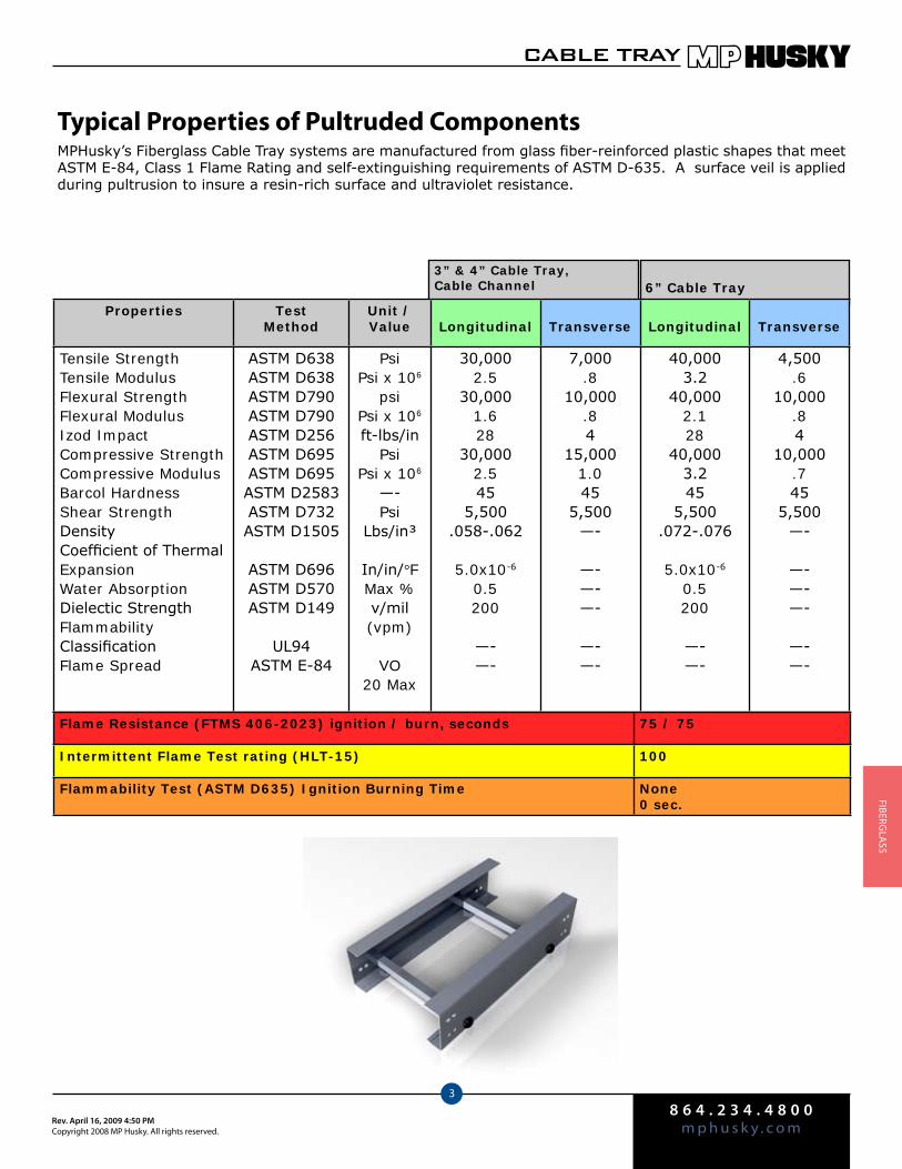
8 6 4 . 2 3 4 . 4 8 0 0m p h u s k y . c o mRev. April 16, 2009 4:50 PM
Copyright 2008 MP Husky. All rights reserved.
CABLE TRAY
3
FIberGlA
SS
Typical Properties of Pultruded ComponentsMPHusky’s Fiberglass Cable Tray systems are manufactured from glass fiber-reinforced plastic shapes that meet ASTM E-84, Class 1 Flame Rating and self-extinguishing requirements of ASTM D-635. A surface veil is applied during pultrusion to insure a resin-rich surface and ultraviolet resistance.
Flame Resistance (FTMS 406-2023) ignition / burn, seconds 75 / 75
Intermittent Flame Test rating (HLT-15) 100
Flammability Test (ASTM D635) Ignition Burning Time None0 sec.
3” & 4” Cable Tray, Cable Channel 6” Cable Tray
Properties TestMethod
Unit /Value Longitudinal Transverse Longitudinal Transverse
Tensile StrengthTensile ModulusFlexural StrengthFlexural ModulusIzod ImpactCompressive StrengthCompressive ModulusBarcol HardnessShear StrengthDensityCoefficient of Thermal ExpansionWater AbsorptionDielectic StrengthFlammabilityClassificationFlame Spread
ASTM D638ASTM D638ASTM D790ASTM D790ASTM D256ASTM D695ASTM D695ASTM D2583ASTM D732ASTM D1505
ASTM D696ASTM D570ASTM D149
UL94ASTM E-84
PsiPsi x 106
psiPsi x 106
ft-lbs/inPsi
Psi x 106
—-Psi
Lbs/in³
In/in/°FMax %v/mil (vpm)
VO20 Max
30,0002.5
30,0001.628
30,0002.545
5,500.058-.062
5.0x10⁻⁶
0.5200
—-—-
7,000.8
10,000.84
15,0001.045
5,500—-
—-—-—-
—-—-
40,0003.2
40,0002.128
40,0003.245
5,500.072-.076
5.0x10⁻⁶
0.5200
—-—-
4,500.6
10,000.84
10,000.745
5,500—-
—-—-—-
—-—-
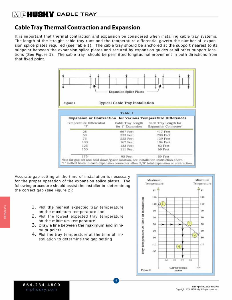
8 6 4 . 2 3 4 . 4 8 0 0m p h u s k y . c o m
Rev. April 16, 2009 4:50 PMCopyright 2008 MP Husky. All rights reserved.
CABLE TRAY
4
FIbe
rGlA
SS
Cable Tray Thermal Contraction and ExpansionIt is important that thermal contraction and expansion be considered when installing cable tray systems. The length of the straight cable tray runs and the temperature differential govern the number of expan-sion splice plates required (see Table 1). The cable tray should be anchored at the support nearest to its midpoint between the expansion splice plates and secured by expansion guides at all other support loca-tions (See Figure 1). The cable tray should be permitted longitudinal movement in both directions from that fixed point.
Plot the highest expected tray temperature 1. on the maximum temperature linePlot the lowest expected tray temperature 2. on the minimum temperatureDraw a line between the maximum and mini-3. mum pointsPlot the tray temperature at the time of in-4. stallation to determine the gap setting
Accurate gap setting at the time of installation is necessary for the proper operation of the expansion splice plates. The following procedure should assist the installer in determining the correct gap (see Figure 2):

8 6 4 . 2 3 4 . 4 8 0 0m p h u s k y . c o mRev. April 16, 2009 4:50 PM
Copyright 2008 MP Husky. All rights reserved.
CABLE TRAY
5
FIberGlA
SS
Cable Tray Installation Guide
Installation of MPHusky Fiberglass Cable Tray should be made in accordance with the standards set by NEMA Publication VE-2 latest edition and National Electrical Code,
Article 392.
Always observe common safety practices when assembling tray and fittings. Installations ♦generally require some field cutting. Dust created during fabrication presents no serious health hazard, but skin irritation may be experienced by some workers.
Operators of saws and drills should wear masks, long sleeve shirts, or coveralls. ♦
Fabrication with Husky Fiberglass is relatively easy and comparable to working with wood. ♦Ordinary hand tools may be used in most cases.
Avoid excessive pressure when sawing or drilling. Too much force can rapidly dull tools and ♦also produce excessive heat which softens the bonding resin in the Husky Fiberglass, result-ing in a ragged edge rather than a clean-cut edge.
Field cutting is simple and can be accomplished with a circular power saw with an abrasive ♦cut-off wheel (masonry type) or hack saw (24 to 32 teeth per inch).
Drill Husky Fiberglass as you would drill hard wood. Standard twist drills are more than ad- ♦equate.
Any surface that has been drilled, cut, sanded or otherwise broken, ♦ must be sealed with a compatible resin.
Carbide tipped saw blades and drill bits are recommended when cutting large quantities. ♦
Support the Husky Fiberglass material firmly during cutting operations to keep material from ♦shifting, which may cause chipping at the cut edge.
Each tray section length should be equal to or greater than the support span. ♦
When possible, the splice should be located at quarter span. ♦
Fittings should be supported as per NEMA VE-2. ♦
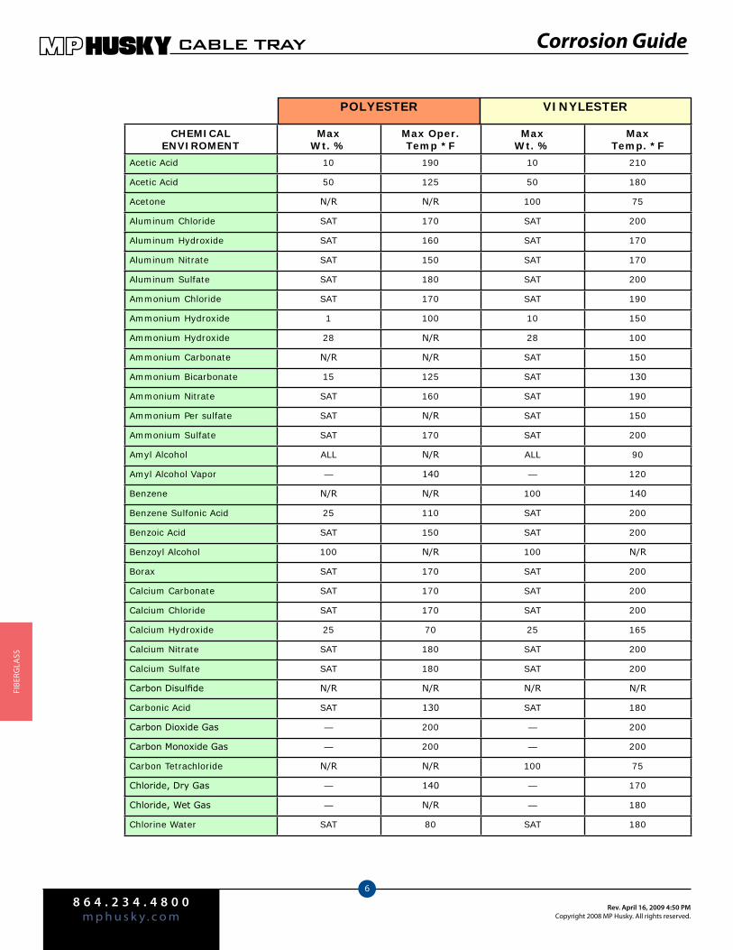
8 6 4 . 2 3 4 . 4 8 0 0m p h u s k y . c o m
Rev. April 16, 2009 4:50 PMCopyright 2008 MP Husky. All rights reserved.
CABLE TRAY
6
FIbe
rGlA
SS
CHEMICAL ENVIROMENT
MaxWt. %
Max Oper.Temp *F
Max Wt. %
MaxTemp. *F
Acetic Acid 10 190 10 210
Acetic Acid 50 125 50 180
Acetone N/R N/R 100 75
Aluminum Chloride SAT 170 SAT 200
Aluminum Hydroxide SAT 160 SAT 170
Aluminum Nitrate SAT 150 SAT 170
Aluminum Sulfate SAT 180 SAT 200
Ammonium Chloride SAT 170 SAT 190
Ammonium Hydroxide 1 100 10 150
Ammonium Hydroxide 28 N/R 28 100
Ammonium Carbonate N/R N/R SAT 150
Ammonium Bicarbonate 15 125 SAT 130
Ammonium Nitrate SAT 160 SAT 190
Ammonium Per sulfate SAT N/R SAT 150
Ammonium Sulfate SAT 170 SAT 200
Amyl Alcohol ALL N/R ALL 90
Amyl Alcohol Vapor — 140 — 120
Benzene N/R N/R 100 140
Benzene Sulfonic Acid 25 110 SAT 200
Benzoic Acid SAT 150 SAT 200
Benzoyl Alcohol 100 N/R 100 N/R
Borax SAT 170 SAT 200
Calcium Carbonate SAT 170 SAT 200
Calcium Chloride SAT 170 SAT 200
Calcium Hydroxide 25 70 25 165
Calcium Nitrate SAT 180 SAT 200
Calcium Sulfate SAT 180 SAT 200
Carbon Disulfide N/R N/R N/R N/R
Carbonic Acid SAT 130 SAT 180
Carbon Dioxide Gas — 200 — 200
Carbon Monoxide Gas — 200 — 200
Carbon Tetrachloride N/R N/R 100 75
Chloride, Dry Gas — 140 — 170
Chloride, Wet Gas — N/R — 180
Chlorine Water SAT 80 SAT 180
POLYESTER VINYLESTER
Corrosion Guide
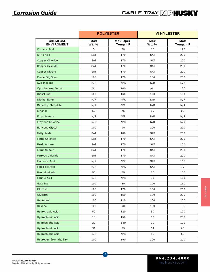
8 6 4 . 2 3 4 . 4 8 0 0m p h u s k y . c o mRev. April 16, 2009 4:50 PM
Copyright 2008 MP Husky. All rights reserved.
CABLE TRAY
7
FIberGlA
SS
POLYESTER VINYLESTER
Corrosion Guide
CHEMICAL ENVIROMENT
MaxWt. %
Max Oper.Temp *F
Max Wt. %
MaxTemp. *F
Chromic Acid 5 70 10 120
Citric Acid SAT 170 SAT 200
Copper Chloride SAT 170 SAT 200
Copper Cyanide SAT 170 SAT 200
Copper Nitrate SAT 170 SAT 200
Crude Oil, Sour 100 170 100 200
Cyclohexane N/R N/R N/R N/R
Cyclohexane, Vapor ALL 100 ALL 130
Diesel Fuel 100 160 100 180
Diethyl Ether N/R N/R N/R N/R
Dimethly Phthalate N/R N/R N/R N/R
Ethanol 50 75 50 90
Ethyl Acetate N/R N/R N/R N/R
Ethylene Chloride N/R N/R N/R N/R
Ethylene Glycol 100 90 100 200
Fatty Acids SAT 180 SAT 200
Ferric Chloride SAT 170 SAT 200
Ferric nitrate SAT 170 SAT 200
Ferric Sulfate SAT 170 SAT 200
Ferrous Chloride SAT 170 SAT 200
Fluoboric Acid N/R N/R SAT 165
Fluosilcic Acid N/R N/R SAT 70
Formaldehyde 50 75 50 100
Formic Acid N/R N/R 50 100
Gasoline 100 80 100 150
Glucose 100 170 100 200
Glycerin 100 150 100 200
Heptanes 100 110 100 200
Hexane 100 90 100 130
Hydrotropic Acid 50 120 50 120
Hydrochloric Acid 10 150 10 200
Hydrochloric Acid 20 140 20 190
Hydrochloric Acid 37 75 37 95
Hydrochloric Acid N/R N/R 15 80
Hydrogen Bromide, Dry 100 190 100 200
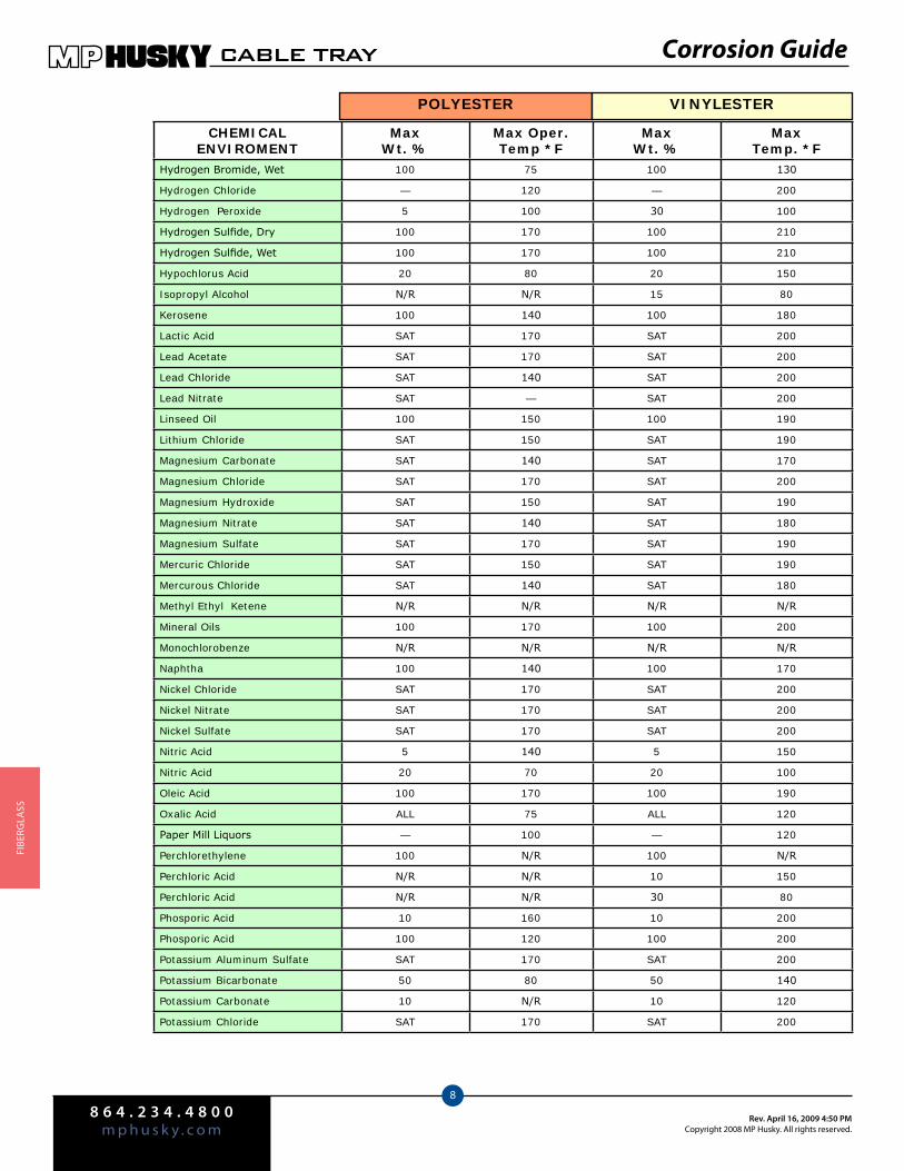
8 6 4 . 2 3 4 . 4 8 0 0m p h u s k y . c o m
Rev. April 16, 2009 4:50 PMCopyright 2008 MP Husky. All rights reserved.
CABLE TRAY
8
FIbe
rGlA
SS
CHEMICAL ENVIROMENT
MaxWt. %
Max Oper.Temp *F
Max Wt. %
MaxTemp. *F
Hydrogen Bromide, Wet 100 75 100 130
Hydrogen Chloride — 120 — 200
Hydrogen Peroxide 5 100 30 100
Hydrogen Sulfide, Dry 100 170 100 210
Hydrogen Sulfide, Wet 100 170 100 210
Hypochlorus Acid 20 80 20 150
Isopropyl Alcohol N/R N/R 15 80
Kerosene 100 140 100 180
Lactic Acid SAT 170 SAT 200
Lead Acetate SAT 170 SAT 200
Lead Chloride SAT 140 SAT 200
Lead Nitrate SAT — SAT 200
Linseed Oil 100 150 100 190
Lithium Chloride SAT 150 SAT 190
Magnesium Carbonate SAT 140 SAT 170
Magnesium Chloride SAT 170 SAT 200
Magnesium Hydroxide SAT 150 SAT 190
Magnesium Nitrate SAT 140 SAT 180
Magnesium Sulfate SAT 170 SAT 190
Mercuric Chloride SAT 150 SAT 190
Mercurous Chloride SAT 140 SAT 180
Methyl Ethyl Ketene N/R N/R N/R N/R
Mineral Oils 100 170 100 200
Monochlorobenze N/R N/R N/R N/R
Naphtha 100 140 100 170
Nickel Chloride SAT 170 SAT 200
Nickel Nitrate SAT 170 SAT 200
Nickel Sulfate SAT 170 SAT 200
Nitric Acid 5 140 5 150
Nitric Acid 20 70 20 100
Oleic Acid 100 170 100 190
Oxalic Acid ALL 75 ALL 120
Paper Mill Liquors — 100 — 120
Perchlorethylene 100 N/R 100 N/R
Perchloric Acid N/R N/R 10 150
Perchloric Acid N/R N/R 30 80
Phosporic Acid 10 160 10 200
Phosporic Acid 100 120 100 200
Potassium Aluminum Sulfate SAT 170 SAT 200
Potassium Bicarbonate 50 80 50 140
Potassium Carbonate 10 N/R 10 120
Potassium Chloride SAT 170 SAT 200
POLYESTER VINYLESTER
Corrosion Guide
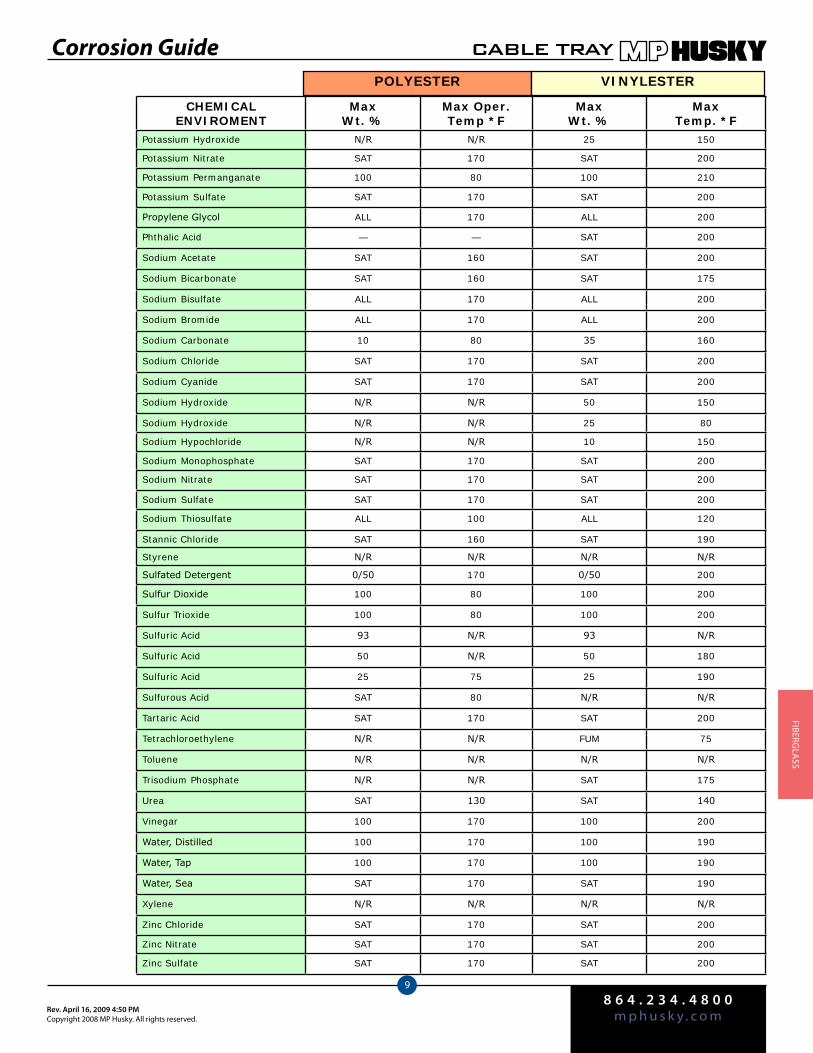
8 6 4 . 2 3 4 . 4 8 0 0m p h u s k y . c o mRev. April 16, 2009 4:50 PM
Copyright 2008 MP Husky. All rights reserved.
CABLE TRAY
9
FIberGlA
SS
CHEMICAL ENVIROMENT
MaxWt. %
Max Oper.Temp *F
Max Wt. %
MaxTemp. *F
Potassium Hydroxide N/R N/R 25 150
Potassium Nitrate SAT 170 SAT 200
Potassium Permanganate 100 80 100 210
Potassium Sulfate SAT 170 SAT 200
Propylene Glycol ALL 170 ALL 200
Phthalic Acid — — SAT 200
Sodium Acetate SAT 160 SAT 200
Sodium Bicarbonate SAT 160 SAT 175
Sodium Bisulfate ALL 170 ALL 200
Sodium Bromide ALL 170 ALL 200
Sodium Carbonate 10 80 35 160
Sodium Chloride SAT 170 SAT 200
Sodium Cyanide SAT 170 SAT 200
Sodium Hydroxide N/R N/R 50 150
Sodium Hydroxide N/R N/R 25 80
Sodium Hypochloride N/R N/R 10 150
Sodium Monophosphate SAT 170 SAT 200
Sodium Nitrate SAT 170 SAT 200
Sodium Sulfate SAT 170 SAT 200
Sodium Thiosulfate ALL 100 ALL 120
Stannic Chloride SAT 160 SAT 190
Styrene N/R N/R N/R N/R
Sulfated Detergent 0/50 170 0/50 200
Sulfur Dioxide 100 80 100 200
Sulfur Trioxide 100 80 100 200
Sulfuric Acid 93 N/R 93 N/R
Sulfuric Acid 50 N/R 50 180
Sulfuric Acid 25 75 25 190
Sulfurous Acid SAT 80 N/R N/R
Tartaric Acid SAT 170 SAT 200
Tetrachloroethylene N/R N/R FUM 75
Toluene N/R N/R N/R N/R
Trisodium Phosphate N/R N/R SAT 175
Urea SAT 130 SAT 140
Vinegar 100 170 100 200
Water, Distilled 100 170 100 190
Water, Tap 100 170 100 190
Water, Sea SAT 170 SAT 190
Xylene N/R N/R N/R N/R
Zinc Chloride SAT 170 SAT 200
Zinc Nitrate SAT 170 SAT 200
Zinc Sulfate SAT 170 SAT 200
POLYESTER VINYLESTER
Corrosion Guide
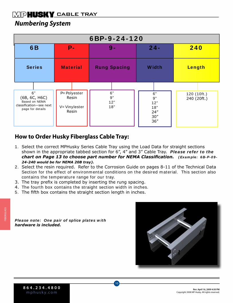
8 6 4 . 2 3 4 . 4 8 0 0m p h u s k y . c o m
Rev. April 16, 2009 4:50 PMCopyright 2008 MP Husky. All rights reserved.
CABLE TRAY
10
FIbe
rGlA
SS
6”(6B, 6C, H6C)Based on NEMA
classification—see next page for details
P=Polyester Resin
V=Vinylester Resin
6”9”12”18”
6”9”12”18”24”30”36”
120 (10ft.) 240 (20ft.)
6BP-9-24-120
Numbering System
How to Order Husky Fiberglass Cable Tray:
Select the correct MPHusky Series Cable Tray using the Load Data for straight sections 1. shown in the appropriate tabbed section for 6”, 4” and 3” Cable Tray. Please refer to the chart on Page 13 to choose part number for NEMA Classification. (Example: 6B-P-09-24-240 would be for NEMA 20B tray). Select the resin required. Refer to the Corrosion Guide on pages 8-11 of the Technical Data 2. Section for the effect of environmental conditions on the desired material. This section also contains the temperature range for our tray. The tray prefix is completed by inserting the rung spacing. 3. The fourth box contains the straight section width in inches. 4. The fifth box contains the straight section length in inches. 5.
Please note: One pair of splice plates with hardware is included.
6B P- 9- 24- 240
Series Material Rung Spacing Width Length
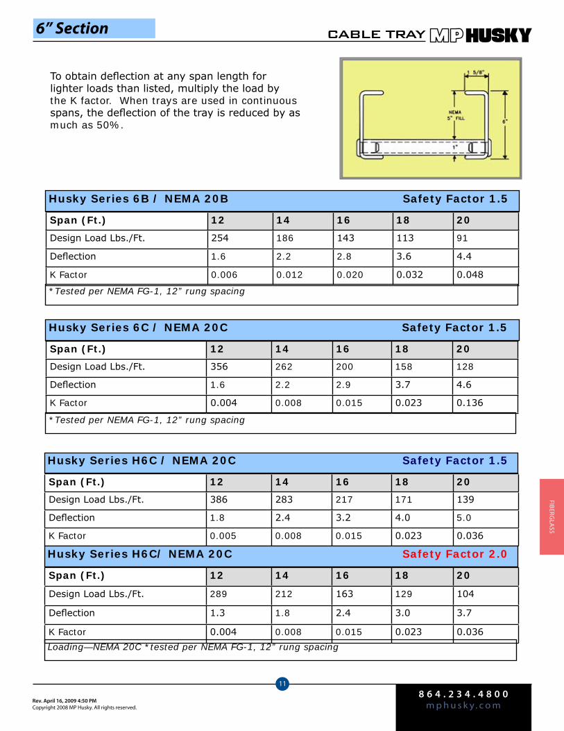
8 6 4 . 2 3 4 . 4 8 0 0m p h u s k y . c o mRev. April 16, 2009 4:50 PM
Copyright 2008 MP Husky. All rights reserved.
CABLE TRAY
11
FIberGlA
SS
Span (Ft.) 12 14 16 18 20
Design Load Lbs./Ft. 254 186 143 113 91
Deflection 1.6 2.2 2.8 3.6 4.4
K Factor 0.006 0.012 0.020 0.032 0.048
Husky Series 6B / NEMA 20B Safety Factor 1.5
*Tested per NEMA FG-1, 12” rung spacing
Span (Ft.) 12 14 16 18 20
Design Load Lbs./Ft. 356 262 200 158 128
Deflection 1.6 2.2 2.9 3.7 4.6
K Factor 0.004 0.008 0.015 0.023 0.136
Husky Series 6C / NEMA 20C Safety Factor 1.5
*Tested per NEMA FG-1, 12” rung spacing
Span (Ft.) 12 14 16 18 20
Design Load Lbs./Ft. 386 283 217 171 139
Deflection 1.8 2.4 3.2 4.0 5.0
K Factor 0.005 0.008 0.015 0.023 0.036
Husky Series H6C / NEMA 20C Safety Factor 1.5
Span (Ft.) 12 14 16 18 20
Design Load Lbs./Ft. 289 212 163 129 104
Deflection 1.3 1.8 2.4 3.0 3.7
K Factor 0.004 0.008 0.015 0.023 0.036
Husky Series H6C/ NEMA 20C Safety Factor 2.0
Loading—NEMA 20C *tested per NEMA FG-1, 12” rung spacing
To obtain deflection at any span length for lighter loads than listed, multiply the load by the K factor. When trays are used in continuous spans, the deflection of the tray is reduced by as much as 50%.
6” Section
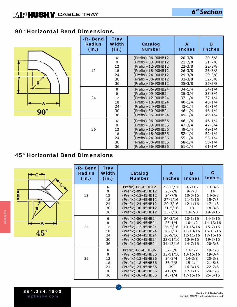
8 6 4 . 2 3 4 . 4 8 0 0m p h u s k y . c o m
Rev. April 16, 2009 4:50 PMCopyright 2008 MP Husky. All rights reserved.
CABLE TRAY
12
FIbe
rGlA
SS
90° Horizontal Bend Dimensions.
45° Horizontal Bend Dimensions
-R- BendRadius (in.)
TrayWidth(in.)
CatalogNumber
AInches
BInches
12
691218243036
(Prefix)-06-90HB12(Prefix)-09-90HB12(Prefix)-12-90HB12(Prefix)-18-90HB12(Prefix)-24-90HB12(Prefix)-30-90HB12(Prefix)-36-90HB12
20-3/821-7/822-3/826-3/829-3/832-3/835-3/8
20-3/821-7/822-3/826-3/829-3/832-3/835-3/8
24
691218243036
(Prefix)-06-90HB24(Prefix)-09-90HB24(Prefix)-12-90HB24(Prefix)-18-90HB24(Prefix)-24-90HB24(Prefix)-30-90HB24(Prefix)-36-90HB24
34-1/435-3/437-1/440-1/443-1/446-1/449-1/4
34-1/435-3/437-1/440-1/443-1/446-1/449-1/4
36
691218243036
(Prefix)-06-90HB36(Prefix)-09-90HB36(Prefix)-12-90HB36(Prefix)-18-90HB36(Prefix)-24-90HB36(Prefix)-30-90HB36(Prefix)-36-90HB36
46-1/447-3/449-1/452-1/455-1/458-1/461-1/4
46-1/447-3/449-1/452-1/455-1/458-1/461-1/4
-R- BendRadius (in.)
TrayWidth(in.)
CatalogNumber
AInches
BInches
CInches
12
691218243036
Prefix)-06-45HB12(Prefix)-09-45HB12(Prefix)-12-45HB12(Prefix)-18-45HB12(Prefix)-24-45HB12(Prefix)-30-45HB12(Prefix)-36-45HB12
22-13/1623-7/824-7/827-1/1629-3/1631-5/1633-7/16
9-7/169-7/8
10-5/1611-3/1612-1/16
1313-7/8
13-3/814
14-5/815-7/817-1/818-3/819-9/16
24
691218243036
(Prefix)-06-45HB24(Prefix)-09-45HB24(Prefix)-12-45HB24(Prefix)-18-45HB24(Prefix)-24-45HB24(Prefix)-30-45HB24(Prefix)-36-45HB24
24-3/1625-1/426-5/1628-7/1630-9/1632-11/1634-13/16
10-1/1610-1/2
10-15/1611-13/1612-11/1613-9/1614-7/16
14-3/1614-13/1615-7/1616-11/1617-15/1619-3/1620-3/8
36
691218243036
Prefix)-06-45HB36(Prefix)-09-45HB36(Prefix)-12-45HB36(Prefix)-18-45HB36(Prefix)-24-45HB36(Prefix)-30-45HB36(Prefix)-36-45HB36
32-5/833-11/1634-3/436-7/8
3941-1/843-1/4
13-1/213-15/1614-3/815-1/416-3/1617-1/1617-15/16
19-1/819-3/420-3/821-5/822-7/824-1/825-5/16
6” Section
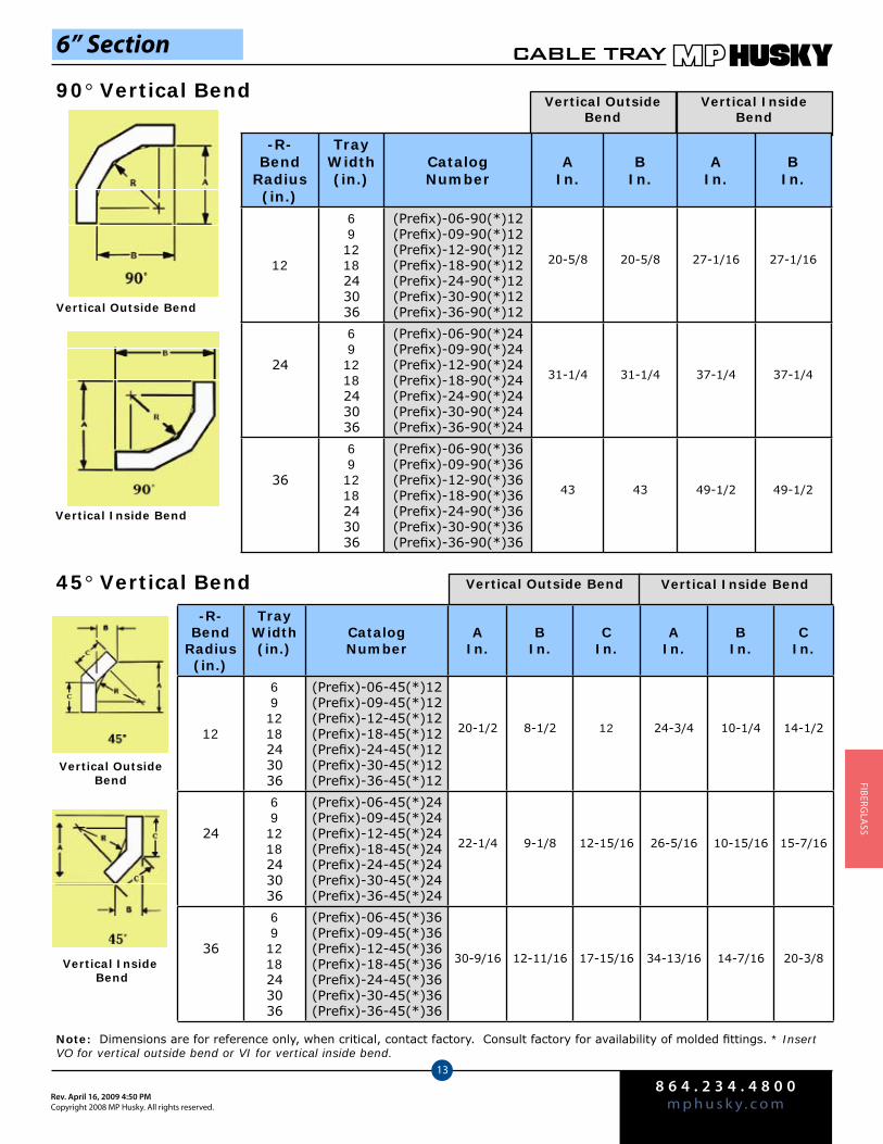
8 6 4 . 2 3 4 . 4 8 0 0m p h u s k y . c o mRev. April 16, 2009 4:50 PM
Copyright 2008 MP Husky. All rights reserved.
CABLE TRAY
13
FIberGlA
SS
6” Section
Vertical Outside Bend
Vertical Inside Bend
Vertical Outside Bend
Vertical Inside Bend
Vertical Outside Bend Vertical Inside Bend45° Vertical Bend
Vertical Outside Bend
Vertical Inside Bend
Note: Dimensions are for reference only, when critical, contact factory. Consult factory for availability of molded fittings. * Insert VO for vertical outside bend or VI for vertical inside bend.
-R- Bend
Radius (in.)
TrayWidth(in.)
CatalogNumber
AIn.
BIn.
AIn.
BIn.
12
691218243036
(Prefix)-06-90(*)12(Prefix)-09-90(*)12(Prefix)-12-90(*)12(Prefix)-18-90(*)12(Prefix)-24-90(*)12(Prefix)-30-90(*)12(Prefix)-36-90(*)12
20-5/8 20-5/8 27-1/16 27-1/16
24
691218243036
(Prefix)-06-90(*)24(Prefix)-09-90(*)24(Prefix)-12-90(*)24(Prefix)-18-90(*)24(Prefix)-24-90(*)24(Prefix)-30-90(*)24(Prefix)-36-90(*)24
31-1/4 31-1/4 37-1/4 37-1/4
36
691218243036
(Prefix)-06-90(*)36(Prefix)-09-90(*)36(Prefix)-12-90(*)36(Prefix)-18-90(*)36(Prefix)-24-90(*)36(Prefix)-30-90(*)36(Prefix)-36-90(*)36
43 43 49-1/2 49-1/2
-R- Bend
Radius (in.)
TrayWidth(in.)
CatalogNumber
AIn.
BIn.
CIn.
AIn.
BIn.
CIn.
12
691218243036
(Prefix)-06-45(*)12(Prefix)-09-45(*)12(Prefix)-12-45(*)12(Prefix)-18-45(*)12(Prefix)-24-45(*)12(Prefix)-30-45(*)12(Prefix)-36-45(*)12
20-1/2 8-1/2 12 24-3/4 10-1/4 14-1/2
24
691218243036
(Prefix)-06-45(*)24(Prefix)-09-45(*)24(Prefix)-12-45(*)24(Prefix)-18-45(*)24(Prefix)-24-45(*)24(Prefix)-30-45(*)24(Prefix)-36-45(*)24
22-1/4 9-1/8 12-15/16 26-5/16 10-15/16 15-7/16
36
691218243036
(Prefix)-06-45(*)36(Prefix)-09-45(*)36(Prefix)-12-45(*)36(Prefix)-18-45(*)36(Prefix)-24-45(*)36(Prefix)-30-45(*)36(Prefix)-36-45(*)36
30-9/16 12-11/16 17-15/16 34-13/16 14-7/16 20-3/8
90° Vertical Bend
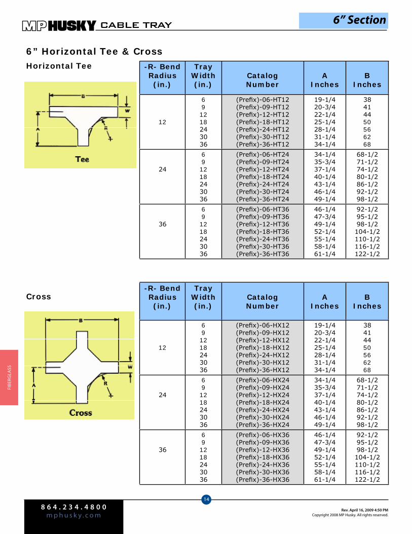
8 6 4 . 2 3 4 . 4 8 0 0m p h u s k y . c o m
Rev. April 16, 2009 4:50 PMCopyright 2008 MP Husky. All rights reserved.
CABLE TRAY
14
FIbe
rGlA
SS
6” Horizontal Tee & Cross
6” Section
-R- BendRadius (in.)
TrayWidth(in.)
CatalogNumber
AInches
BInches
12
691218243036
(Prefix)-06-HT12(Prefix)-09-HT12(Prefix)-12-HT12(Prefix)-18-HT12(Prefix)-24-HT12(Prefix)-30-HT12(Prefix)-36-HT12
19-1/420-3/422-1/425-1/428-1/431-1/434-1/4
38414450566268
24
691218243036
(Prefix)-06-HT24(Prefix)-09-HT24(Prefix)-12-HT24(Prefix)-18-HT24(Prefix)-24-HT24(Prefix)-30-HT24(Prefix)-36-HT24
34-1/435-3/437-1/440-1/443-1/446-1/449-1/4
68-1/271-1/274-1/280-1/286-1/292-1/298-1/2
36
691218243036
(Prefix)-06-HT36(Prefix)-09-HT36(Prefix)-12-HT36(Prefix)-18-HT36(Prefix)-24-HT36(Prefix)-30-HT36(Prefix)-36-HT36
46-1/447-3/449-1/452-1/455-1/458-1/461-1/4
92-1/295-1/298-1/2104-1/2110-1/2116-1/2122-1/2
Horizontal Tee
-R- BendRadius (in.)
TrayWidth(in.)
CatalogNumber
AInches
BInches
12
691218243036
(Prefix)-06-HX12(Prefix)-09-HX12(Prefix)-12-HX12(Prefix)-18-HX12(Prefix)-24-HX12(Prefix)-30-HX12(Prefix)-36-HX12
19-1/420-3/422-1/425-1/428-1/431-1/434-1/4
38414450566268
24
691218243036
(Prefix)-06-HX24(Prefix)-09-HX24(Prefix)-12-HX24(Prefix)-18-HX24(Prefix)-24-HX24(Prefix)-30-HX24(Prefix)-36-HX24
34-1/435-3/437-1/440-1/443-1/446-1/449-1/4
68-1/271-1/274-1/280-1/286-1/292-1/298-1/2
36
691218243036
(Prefix)-06-HX36(Prefix)-09-HX36(Prefix)-12-HX36(Prefix)-18-HX36(Prefix)-24-HX36(Prefix)-30-HX36(Prefix)-36-HX36
46-1/447-3/449-1/452-1/455-1/458-1/461-1/4
92-1/295-1/298-1/2104-1/2110-1/2116-1/2122-1/2
Cross
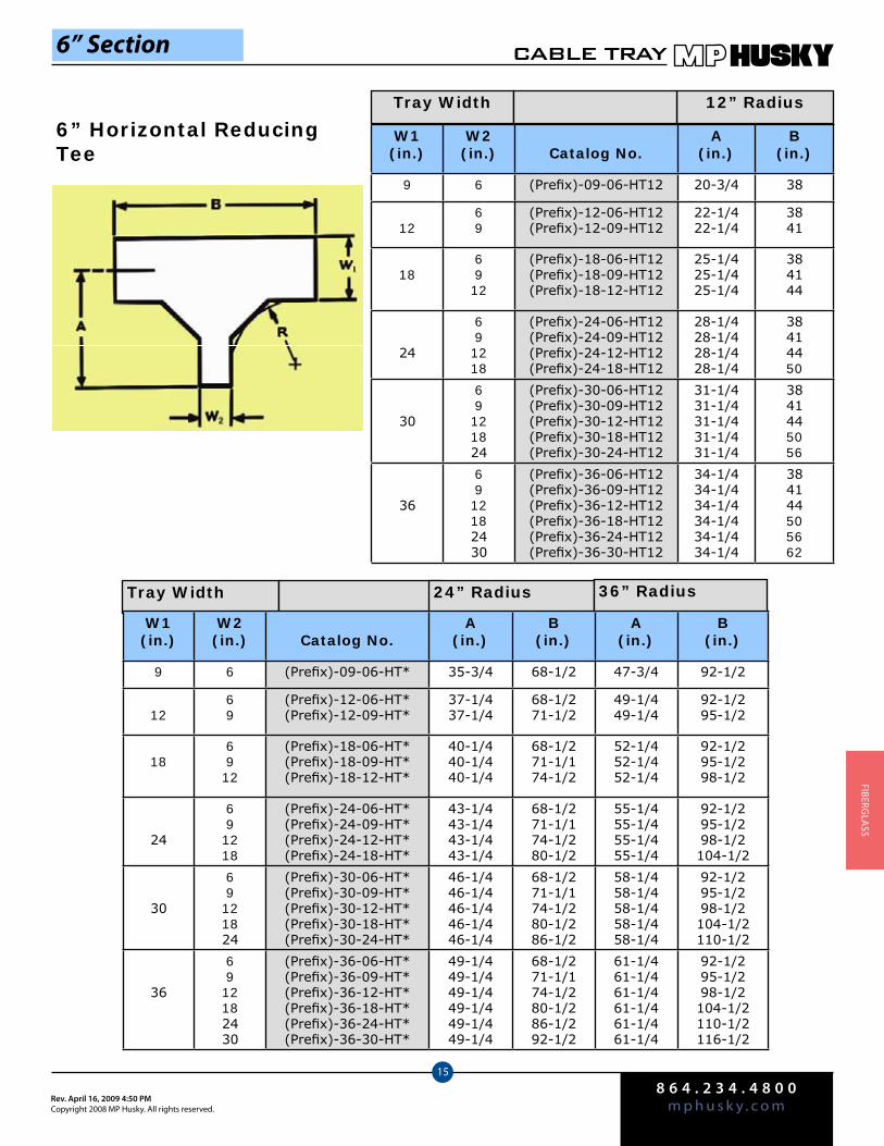
8 6 4 . 2 3 4 . 4 8 0 0m p h u s k y . c o mRev. April 16, 2009 4:50 PM
Copyright 2008 MP Husky. All rights reserved.
CABLE TRAY
15
FIberGlA
SS
6” Horizontal Reducing Tee
Tray Width
W1(in.)
W2(in.) Catalog No.
A(in.)
B(in.)
9 6 (Prefix)-09-06-HT12 20-3/4 38
1269
(Prefix)-12-06-HT12(Prefix)-12-09-HT12
22-1/422-1/4
3841
186912
(Prefix)-18-06-HT12(Prefix)-18-09-HT12(Prefix)-18-12-HT12
25-1/425-1/425-1/4
384144
24
691218
(Prefix)-24-06-HT12(Prefix)-24-09-HT12(Prefix)-24-12-HT12(Prefix)-24-18-HT12
28-1/428-1/428-1/428-1/4
38414450
30
69121824
(Prefix)-30-06-HT12(Prefix)-30-09-HT12(Prefix)-30-12-HT12(Prefix)-30-18-HT12(Prefix)-30-24-HT12
31-1/431-1/431-1/431-1/431-1/4
3841445056
36
6912182430
(Prefix)-36-06-HT12(Prefix)-36-09-HT12(Prefix)-36-12-HT12(Prefix)-36-18-HT12(Prefix)-36-24-HT12(Prefix)-36-30-HT12
34-1/434-1/434-1/434-1/434-1/434-1/4
384144505662
Tray Width 12” Radius
6” Section
24” Radius 36” Radius
W1(in.)
W2(in.) Catalog No.
A(in.)
B(in.)
A(in.)
B(in.)
9 6 (Prefix)-09-06-HT* 35-3/4 68-1/2 47-3/4 92-1/2
1269
(Prefix)-12-06-HT*(Prefix)-12-09-HT*
37-1/437-1/4
68-1/271-1/2
49-1/449-1/4
92-1/295-1/2
186912
(Prefix)-18-06-HT*(Prefix)-18-09-HT*(Prefix)-18-12-HT*
40-1/440-1/440-1/4
68-1/271-1/174-1/2
52-1/452-1/452-1/4
92-1/295-1/298-1/2
24
691218
(Prefix)-24-06-HT*(Prefix)-24-09-HT*(Prefix)-24-12-HT*(Prefix)-24-18-HT*
43-1/443-1/443-1/443-1/4
68-1/271-1/174-1/280-1/2
55-1/455-1/455-1/455-1/4
92-1/295-1/298-1/2104-1/2
30
69121824
(Prefix)-30-06-HT*(Prefix)-30-09-HT*(Prefix)-30-12-HT*(Prefix)-30-18-HT*(Prefix)-30-24-HT*
46-1/446-1/446-1/446-1/446-1/4
68-1/271-1/174-1/280-1/286-1/2
58-1/458-1/458-1/458-1/458-1/4
92-1/295-1/298-1/2104-1/2110-1/2
36
6912182430
(Prefix)-36-06-HT*(Prefix)-36-09-HT*(Prefix)-36-12-HT*(Prefix)-36-18-HT*(Prefix)-36-24-HT*(Prefix)-36-30-HT*
49-1/449-1/449-1/449-1/449-1/449-1/4
68-1/271-1/174-1/280-1/286-1/292-1/2
61-1/461-1/461-1/461-1/461-1/461-1/4
92-1/295-1/298-1/2104-1/2110-1/2116-1/2
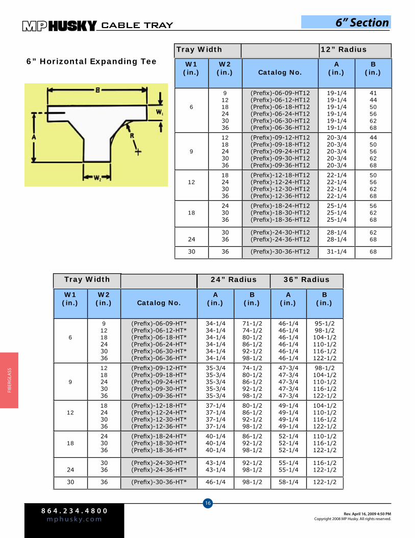
8 6 4 . 2 3 4 . 4 8 0 0m p h u s k y . c o m
Rev. April 16, 2009 4:50 PMCopyright 2008 MP Husky. All rights reserved.
CABLE TRAY
16
FIbe
rGlA
SS
6” Horizontal Expanding TeeTray Width 12” Radius
6” Section
W1(in.)
W2(in.) Catalog No.
A(in.)
B(in.)
6
91218243036
(Prefix)-06-09-HT12(Prefix)-06-12-HT12(Prefix)-06-18-HT12(Prefix)-06-24-HT12(Prefix)-06-30-HT12(Prefix)-06-36-HT12
19-1/419-1/419-1/419-1/419-1/419-1/4
414450566268
9
1218243036
(Prefix)-09-12-HT12(Prefix)-09-18-HT12(Prefix)-09-24-HT12(Prefix)-09-30-HT12(Prefix)-09-36-HT12
20-3/420-3/420-3/420-3/420-3/4
4450566268
1218243036
(Prefix)-12-18-HT12(Prefix)-12-24-HT12(Prefix)-12-30-HT12(Prefix)-12-36-HT12
22-1/422-1/422-1/422-1/4
50566268
18243036
(Prefix)-18-24-HT12(Prefix)-18-30-HT12(Prefix)-18-36-HT12
25-1/425-1/425-1/4
566268
243036
(Prefix)-24-30-HT12(Prefix)-24-36-HT12
28-1/428-1/4
6268
30 36 (Prefix)-30-36-HT12 31-1/4 68
Tray Width 24” Radius 36” Radius
W1(in.)
W2(in.) Catalog No.
A(in.)
B(in.)
A(in.)
B(in.)
6
91218243036
(Prefix)-06-09-HT*(Prefix)-06-12-HT*(Prefix)-06-18-HT*(Prefix)-06-24-HT*(Prefix)-06-30-HT*(Prefix)-06-36-HT*
34-1/434-1/434-1/434-1/434-1/434-1/4
71-1/274-1/280-1/286-1/292-1/298-1/2
46-1/446-1/446-1/446-1/446-1/446-1/4
95-1/298-1/2104-1/2110-1/2116-1/2122-1/2
9
1218243036
(Prefix)-09-12-HT*(Prefix)-09-18-HT*(Prefix)-09-24-HT*(Prefix)-09-30-HT*(Prefix)-09-36-HT*
35-3/435-3/435-3/435-3/435-3/4
74-1/280-1/286-1/292-1/298-1/2
47-3/447-3/447-3/447-3/447-3/4
98-1/2104-1/2110-1/2116-1/2122-1/2
1218243036
(Prefix)-12-18-HT*(Prefix)-12-24-HT*(Prefix)-12-30-HT*(Prefix)-12-36-HT*
37-1/437-1/437-1/437-1/4
80-1/286-1/292-1/298-1/2
49-1/449-1/449-1/449-1/4
104-1/2110-1/2116-1/2122-1/2
18243036
(Prefix)-18-24-HT*(Prefix)-18-30-HT*(Prefix)-18-36-HT*
40-1/440-1/440-1/4
86-1/292-1/298-1/2
52-1/452-1/452-1/4
110-1/2116-1/2122-1/2
243036
(Prefix)-24-30-HT*(Prefix)-24-36-HT*
43-1/443-1/4
92-1/298-1/2
55-1/455-1/4
116-1/2122-1/2
30 36 (Prefix)-30-36-HT* 46-1/4 98-1/2 58-1/4 122-1/2
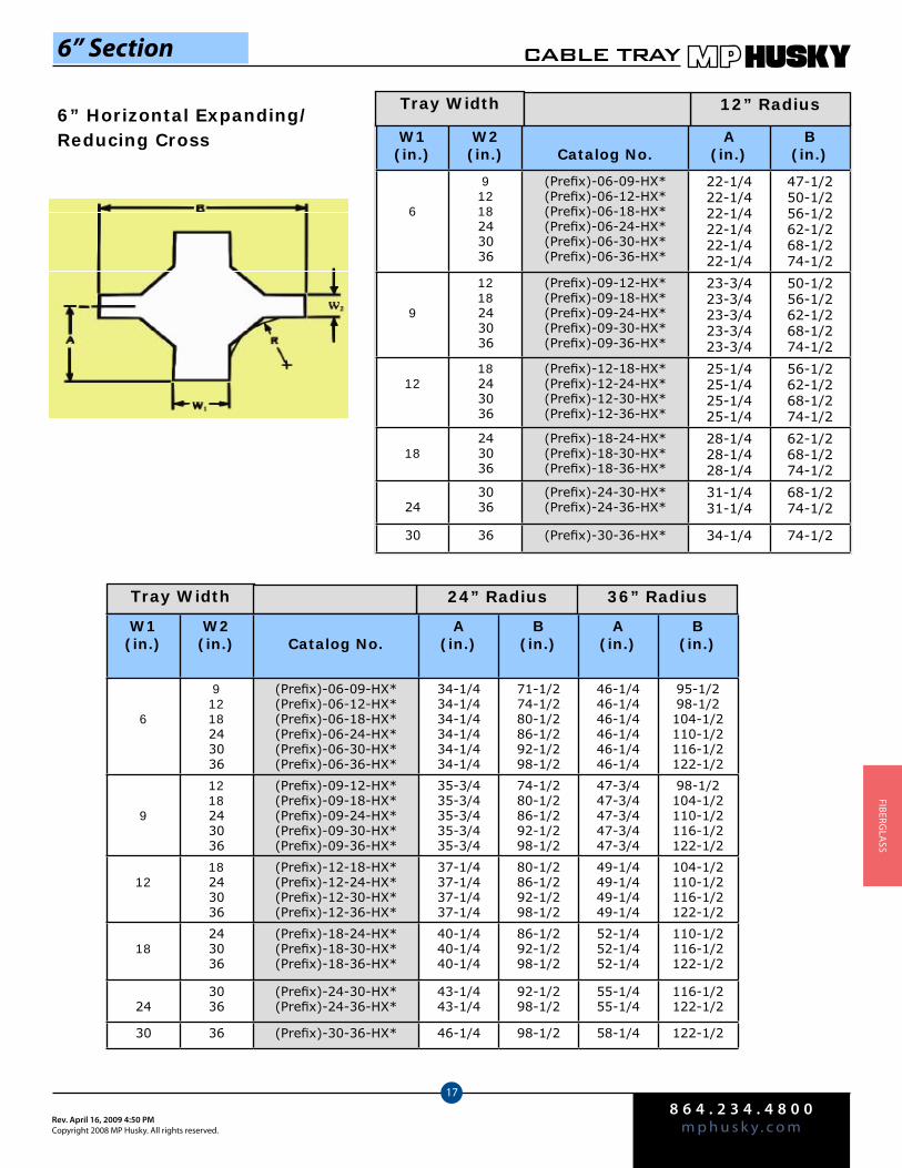
8 6 4 . 2 3 4 . 4 8 0 0m p h u s k y . c o mRev. April 16, 2009 4:50 PM
Copyright 2008 MP Husky. All rights reserved.
CABLE TRAY
17
FIberGlA
SS
6” Horizontal Expanding/ Reducing Cross W1
(in.)W2(in.) Catalog No.
A(in.)
B(in.)
6
91218243036
(Prefix)-06-09-HX*(Prefix)-06-12-HX*(Prefix)-06-18-HX*(Prefix)-06-24-HX*(Prefix)-06-30-HX*(Prefix)-06-36-HX*
22-1/422-1/422-1/422-1/422-1/422-1/4
47-1/250-1/256-1/262-1/268-1/274-1/2
9
1218243036
(Prefix)-09-12-HX*(Prefix)-09-18-HX*(Prefix)-09-24-HX*(Prefix)-09-30-HX*(Prefix)-09-36-HX*
23-3/423-3/423-3/423-3/423-3/4
50-1/256-1/262-1/268-1/274-1/2
1218243036
(Prefix)-12-18-HX*(Prefix)-12-24-HX*(Prefix)-12-30-HX*(Prefix)-12-36-HX*
25-1/425-1/425-1/425-1/4
56-1/262-1/268-1/274-1/2
18243036
(Prefix)-18-24-HX*(Prefix)-18-30-HX*(Prefix)-18-36-HX*
28-1/428-1/428-1/4
62-1/268-1/274-1/2
243036
(Prefix)-24-30-HX*(Prefix)-24-36-HX*
31-1/431-1/4
68-1/274-1/2
30 36 (Prefix)-30-36-HX* 34-1/4 74-1/2
Tray Width 12” Radius
6” Section
Tray Width 24” Radius 36” Radius
W1(in.)
W2(in.) Catalog No.
A(in.)
B(in.)
A(in.)
B(in.)
6
91218243036
(Prefix)-06-09-HX*(Prefix)-06-12-HX*(Prefix)-06-18-HX*(Prefix)-06-24-HX*(Prefix)-06-30-HX*(Prefix)-06-36-HX*
34-1/434-1/434-1/434-1/434-1/434-1/4
71-1/274-1/280-1/286-1/292-1/298-1/2
46-1/446-1/446-1/446-1/446-1/446-1/4
95-1/298-1/2104-1/2110-1/2116-1/2122-1/2
9
1218243036
(Prefix)-09-12-HX*(Prefix)-09-18-HX*(Prefix)-09-24-HX*(Prefix)-09-30-HX*(Prefix)-09-36-HX*
35-3/435-3/435-3/435-3/435-3/4
74-1/280-1/286-1/292-1/298-1/2
47-3/447-3/447-3/447-3/447-3/4
98-1/2104-1/2110-1/2116-1/2122-1/2
1218243036
(Prefix)-12-18-HX*(Prefix)-12-24-HX*(Prefix)-12-30-HX*(Prefix)-12-36-HX*
37-1/437-1/437-1/437-1/4
80-1/286-1/292-1/298-1/2
49-1/449-1/449-1/449-1/4
104-1/2110-1/2116-1/2122-1/2
18243036
(Prefix)-18-24-HX*(Prefix)-18-30-HX*(Prefix)-18-36-HX*
40-1/440-1/440-1/4
86-1/292-1/298-1/2
52-1/452-1/452-1/4
110-1/2116-1/2122-1/2
243036
(Prefix)-24-30-HX*(Prefix)-24-36-HX*
43-1/443-1/4
92-1/298-1/2
55-1/455-1/4
116-1/2122-1/2
30 36 (Prefix)-30-36-HX* 46-1/4 98-1/2 58-1/4 122-1/2
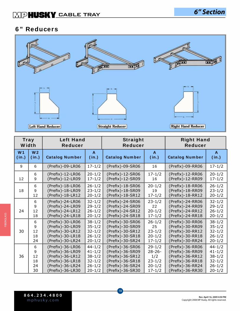
8 6 4 . 2 3 4 . 4 8 0 0m p h u s k y . c o m
Rev. April 16, 2009 4:50 PMCopyright 2008 MP Husky. All rights reserved.
CABLE TRAY
18
FIbe
rGlA
SS
6” Reducers
6” Section
Tray Width
Left HandReducer
StraightReducer
Right HandReducer
W1(in.)
W2(in.) Catalog Number
A(in.) Catalog Number
A(in.) Catalog Number
A(in.)
9 6 (Prefix)-09-LR06 17-1/2 (Prefix)-09-SR06 16 (Prefix)-09-RR06 17-1/2
1269
(Prefix)-12-LR06(Prefix)-12-LR09
20-1/217-1/2
(Prefix)-12-SR06(Prefix)-12-SR09
17-1/216
(Prefix)-12-RR06(Prefix)-12-RR09
20-1/217-1/2
186912
(Prefix)-18-LR06(Prefix)-18-LR09(Prefix)-18-LR12
26-1/223-1/220-1/2
(Prefix)-18-SR06(Prefix)-18-SR09(Prefix)-18-SR12
20-1/219
17-1/2
(Prefix)-18-RR06(Prefix)-18-RR09(Prefix)-18-RR12
26-1/223-1/220-1/2
24
691218
(Prefix)-24-LR06(Prefix)-24-LR09(Prefix)-24-LR12(Prefix)-24-LR18
32-1/229-1/226-1/220-1/2
(Prefix)-24-SR06(Prefix)-24-SR09(Prefix)-24-SR12(Prefix)-24-SR18
23-1/222
20-1/217-1/2
(Prefix)-24-RR06(Prefix)-24-RR09(Prefix)-24-RR12(Prefix)-24-RR18
32-1/229-1/226-1/220-1/2
30
69121824
(Prefix)-30-LR06(Prefix)-30-LR09(Prefix)-30-LR12(Prefix)-30-LR18(Prefix)-30-LR24
38-1/235-1/232-1/226-1/220-1/2
(Prefix)-30-SR06(Prefix)-30-SR09(Prefix)-30-SR12(Prefix)-30-SR18(Prefix)-30-SR24
26-1/225
23-1/220-1/217-1/2
(Prefix)-30-RR06(Prefix)-30-RR09(Prefix)-30-RR12(Prefix)-30-RR18(Prefix)-30-RR24
38-1/235-1/232-1/226-1/220-1/2
36
6912182430
(Prefix)-36-LR06(Prefix)-36-LR09(Prefix)-36-LR12(Prefix)-36-LR18(Prefix)-36-LR24(Prefix)-36-LR30
44-1/241-1/238-1/232-1/226-1/220-1/2
(Prefix)-36-SR06(Prefix)-36-SR09(Prefix)-36-SR12(Prefix)-36-SR18(Prefix)-36-SR24(Prefix)-36-SR30
29-1/228-26-
1/223-1/220-1/217-1/2
(Prefix)-36-RR06(Prefix)-36-RR09(Prefix)-36-RR12(Prefix)-36-RR18(Prefix)-36-RR24(Prefix)-36-RR30
44-1/241-1/238-1/232-1/226-1/220-1/2
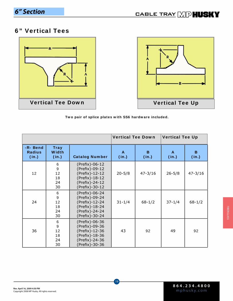
8 6 4 . 2 3 4 . 4 8 0 0m p h u s k y . c o mRev. April 16, 2009 4:50 PM
Copyright 2008 MP Husky. All rights reserved.
CABLE TRAY
19
FIberGlA
SS
6” Vertical Tees
Vertical Tee Down Vertical Tee Up
Two pair of splice plates with SS6 hardware included.
-R- BendRadius(in.)
Tray Width(in.) Catalog Number
A(in.)
B(in.)
A(in.)
B(in.)
12
6912182430
(Prefix)-06-12(Prefix)-09-12(Prefix)-12-12(Prefix)-18-12(Prefix)-24-12(Prefix)-30-12
20-5/8 47-3/16 26-5/8 47-3/16
24
6912182430
(Prefix)-06-24(Prefix)-09-24(Prefix)-12-24(Prefix)-18-24(Prefix)-24-24(Prefix)-30-24
31-1/4 68-1/2 37-1/4 68-1/2
36
6912182430
(Prefix)-06-36(Prefix)-09-36(Prefix)-12-36(Prefix)-18-36(Prefix)-24-36(Prefix)-30-36
43 92 49 92
Vertical Tee Down Vertical Tee Up
6” Section
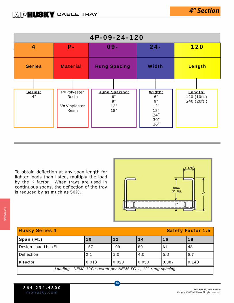
8 6 4 . 2 3 4 . 4 8 0 0m p h u s k y . c o m
Rev. April 16, 2009 4:50 PMCopyright 2008 MP Husky. All rights reserved.
CABLE TRAY
20
FIbe
rGlA
SS
4” Section
Series:4”
P=Polyester Resin
V=Vinylester Resin
Rung Spacing:6”9”12”18”
Width:6”9”12”18”24”30”36”
Length:120 (10ft.) 240 (20ft.)
To obtain deflection at any span length for lighter loads than listed, multiply the load by the K factor. When trays are used in continuous spans, the deflection of the tray is reduced by as much as 50%.
Span (Ft.) 10 12 14 16 18
Design Load Lbs./Ft. 157 109 80 61 48
Deflection 2.1 3.0 4.0 5.3 6.7
K Factor 0.013 0.028 0.050 0.087 0.140
Husky Series 4 Safety Factor 1.5
Loading—NEMA 12C *tested per NEMA FG-1, 12” rung spacing
4P-09-24-1204 P- 09- 24- 120
Series Material Rung Spacing Width Length
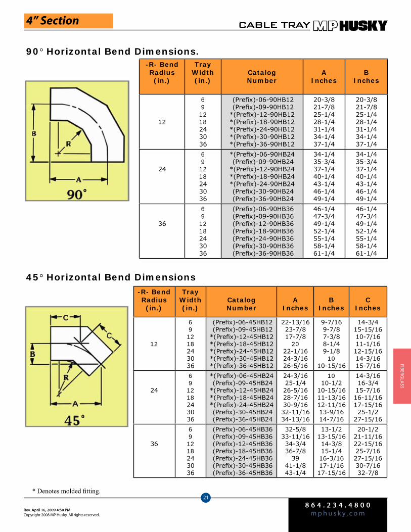
8 6 4 . 2 3 4 . 4 8 0 0m p h u s k y . c o mRev. April 16, 2009 4:50 PM
Copyright 2008 MP Husky. All rights reserved.
CABLE TRAY
21
FIberGlA
SS
4” Section
90° Horizontal Bend Dimensions.
45° Horizontal Bend Dimensions
-R- BendRadius (in.)
TrayWidth(in.)
CatalogNumber
AInches
BInches
12
691218243036
(Prefix)-06-90HB12 (Prefix)-09-90HB12*(Prefix)-12-90HB12*(Prefix)-18-90HB12*(Prefix)-24-90HB12*(Prefix)-30-90HB12*(Prefix)-36-90HB12
20-3/821-7/825-1/428-1/431-1/434-1/437-1/4
20-3/821-7/825-1/428-1/431-1/434-1/437-1/4
24
691218243036
*(Prefix)-06-90HB24 (Prefix)-09-90HB24*(Prefix)-12-90HB24*(Prefix)-18-90HB24*(Prefix)-24-90HB24 (Prefix)-30-90HB24 (Prefix)-36-90HB24
34-1/435-3/437-1/440-1/443-1/446-1/449-1/4
34-1/435-3/437-1/440-1/443-1/446-1/449-1/4
36
691218243036
(Prefix)-06-90HB36 (Prefix)-09-90HB36 (Prefix)-12-90HB36 (Prefix)-18-90HB36 (Prefix)-24-90HB36 (Prefix)-30-90HB36 (Prefix)-36-90HB36
46-1/447-3/449-1/452-1/455-1/458-1/461-1/4
46-1/447-3/449-1/452-1/455-1/458-1/461-1/4
* Denotes molded fitting.
-R- BendRadius (in.)
TrayWidth(in.)
CatalogNumber
AInches
BInches
CInches
12
691218243036
(Prefix)-06-45HB12 (Prefix)-09-45HB12*(Prefix)-12-45HB12*(Prefix)-18-45HB12*(Prefix)-24-45HB12*(Prefix)-30-45HB12*(Prefix)-36-45HB12
22-13/1623-7/817-7/8
2022-1/1624-3/1626-5/16
9-7/169-7/87-3/88-1/49-1/8
1010-15/16
14-3/415-15/1610-7/1611-1/1612-15/1614-3/1615-7/16
24
691218243036
*(Prefix)-06-45HB24 (Prefix)-09-45HB24*(Prefix)-12-45HB24*(Prefix)-18-45HB24*(Prefix)-24-45HB24 (Prefix)-30-45HB24 (Prefix)-36-45HB24
24-3/1625-1/426-5/1628-7/1630-9/1632-11/1634-13/16
1010-1/2
10-15/1611-13/1612-11/1613-9/1614-7/16
14-3/1616-3/415-7/1616-11/1617-15/1625-1/2
27-15/16
36
691218243036
(Prefix)-06-45HB36 (Prefix)-09-45HB36 (Prefix)-12-45HB36 (Prefix)-18-45HB36 (Prefix)-24-45HB36 (Prefix)-30-45HB36 (Prefix)-36-45HB36
32-5/833-11/1634-3/436-7/8
3941-1/843-1/4
13-1/213-15/1614-3/815-1/416-3/1617-1/1617-15/16
20-1/221-11/1622-15/1625-7/1627-15/1630-7/1632-7/8

8 6 4 . 2 3 4 . 4 8 0 0m p h u s k y . c o m
Rev. April 16, 2009 4:50 PMCopyright 2008 MP Husky. All rights reserved.
CABLE TRAY
22
FIbe
rGlA
SS
4” Section
90° Vertical Bend Dimensions
45° Vertical Bend Dimensions
Vertical Outside Bend
Vertical Inside Bend
Vertical Outside Bend
Vertical Inside Bend
Vertical Inside BendVertical Outside Bend
Vertical Outside Bend
Vertical Inside Bend
Note: Dimensions are for reference only, when critical, contact factory. Consult factory for availability of molded fittings. * Insert VO for vertical outside bend or VI for vertical inside bend.
Tray Width
W1(in.)
W2(in.) Catalog No.
A(in.)
B(in.)
A(in.)
B(in.)
12
691218243036
*(Prefix)-06-90(*)12*(Prefix)-09-90(*)12*(Prefix)-12-90(*)12*(Prefix)-18-90(*)12*(Prefix)-24-90(*)12*(Prefix)-30-90(*)12*(Prefix)-36-90(*)12
19-1/4 19-1/4 23-1/4 23-1/4
24
691218243036
(Prefix)-6-90(*)24(Prefix)-9-90(*)24(Prefix)-12-90(*)24(Prefix)-18-90(*)24(Prefix)-24-90(*)24(Prefix)-30-90(*)24(Prefix)-36-90(*)24
31 31 35-1/2 35-1/2
36691218243036
(Prefix)-6-90(*)24(Prefix)-9-90(*)24(Prefix)-12-90(*)24(Prefix)-18-90(*)24(Prefix)-24-90(*)24(Prefix)-30-90(*)24(Prefix)-36-90(*)24
43 43 48-1/2 48-1/2
-R- Bend
Radius (in.)
TrayWidth(in.)
CatalogNumber
AIn.
BIn.
CIn.
AIn.
BIn.
CIn.
12
691218243036
*(Prefix)-06-45(*)12*(Prefix)-09-45(*)12*(Prefix)-12-45(*)12*(Prefix)-18-45(*)12*(Prefix)-24-45(*)12*(Prefix)-30-45(*)12*(Prefix)-36-45(*)12
13-5/8 5-5/8 8 16-7/8 2-13/16 6-13/16
24
691218243036
(Prefix)-6-45(*)24(Prefix)-9-45(*)24(Prefix)-12-45(*)24(Prefix)-18-45(*)24(Prefix)-24-45(*)24(Prefix)-30-45(*)24(Prefix)-36-45(*)24
22-1/16 9-1/8 12-15/16 24-15/16 10-5/16 14-5/8
36
691218243036
(Prefix)-6-45(*)36(Prefix)-9-45(*)36(Prefix)-12-45(*)36(Prefix)-18-45(*)36(Prefix)-24-45(*)36(Prefix)-30-45(*)36(Prefix)-36-45(*)36
37-7/16 15-1/2 21-15/16 40-5/16 16-11/16 23-5/8
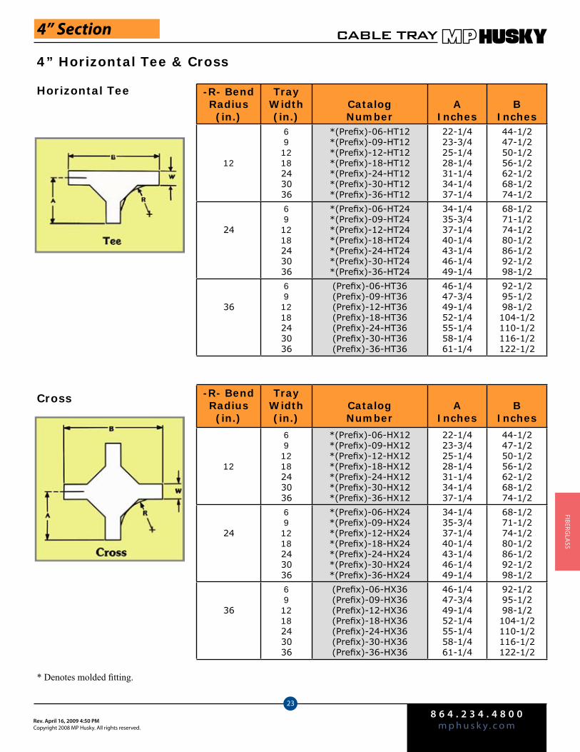
8 6 4 . 2 3 4 . 4 8 0 0m p h u s k y . c o mRev. April 16, 2009 4:50 PM
Copyright 2008 MP Husky. All rights reserved.
CABLE TRAY
23
FIberGlA
SS
4” Horizontal Tee & Cross
4” Section
-R- BendRadius (in.)
TrayWidth(in.)
CatalogNumber
AInches
BInches
12
691218243036
*(Prefix)-06-HT12*(Prefix)-09-HT12*(Prefix)-12-HT12*(Prefix)-18-HT12*(Prefix)-24-HT12*(Prefix)-30-HT12*(Prefix)-36-HT12
22-1/423-3/425-1/428-1/431-1/434-1/437-1/4
44-1/247-1/250-1/256-1/262-1/268-1/274-1/2
24
691218243036
*(Prefix)-06-HT24*(Prefix)-09-HT24*(Prefix)-12-HT24*(Prefix)-18-HT24*(Prefix)-24-HT24*(Prefix)-30-HT24*(Prefix)-36-HT24
34-1/435-3/437-1/440-1/443-1/446-1/449-1/4
68-1/271-1/274-1/280-1/286-1/292-1/298-1/2
36
691218243036
(Prefix)-06-HT36(Prefix)-09-HT36(Prefix)-12-HT36(Prefix)-18-HT36(Prefix)-24-HT36(Prefix)-30-HT36(Prefix)-36-HT36
46-1/447-3/449-1/452-1/455-1/458-1/461-1/4
92-1/295-1/298-1/2104-1/2110-1/2116-1/2122-1/2
Horizontal Tee
-R- BendRadius (in.)
TrayWidth(in.)
CatalogNumber
AInches
BInches
12
691218243036
*(Prefix)-06-HX12*(Prefix)-09-HX12*(Prefix)-12-HX12*(Prefix)-18-HX12*(Prefix)-24-HX12*(Prefix)-30-HX12*(Prefix)-36-HX12
22-1/423-3/425-1/428-1/431-1/434-1/437-1/4
44-1/247-1/250-1/256-1/262-1/268-1/274-1/2
24
691218243036
*(Prefix)-06-HX24*(Prefix)-09-HX24*(Prefix)-12-HX24*(Prefix)-18-HX24*(Prefix)-24-HX24*(Prefix)-30-HX24*(Prefix)-36-HX24
34-1/435-3/437-1/440-1/443-1/446-1/449-1/4
68-1/271-1/274-1/280-1/286-1/292-1/298-1/2
36
691218243036
(Prefix)-06-HX36(Prefix)-09-HX36(Prefix)-12-HX36(Prefix)-18-HX36(Prefix)-24-HX36(Prefix)-30-HX36(Prefix)-36-HX36
46-1/447-3/449-1/452-1/455-1/458-1/461-1/4
92-1/295-1/298-1/2104-1/2110-1/2116-1/2122-1/2
Cross
* Denotes molded fitting.
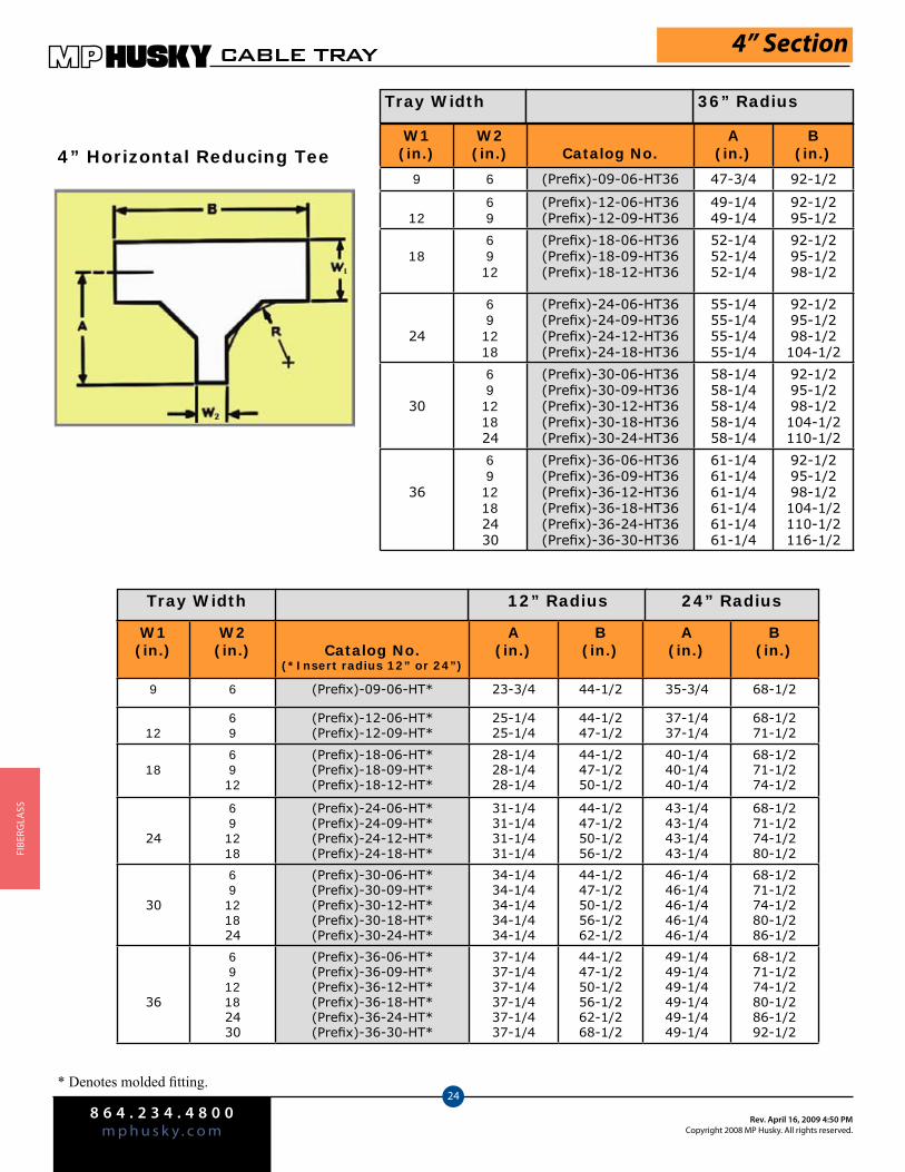
8 6 4 . 2 3 4 . 4 8 0 0m p h u s k y . c o m
Rev. April 16, 2009 4:50 PMCopyright 2008 MP Husky. All rights reserved.
CABLE TRAY
24
FIbe
rGlA
SS
4” Horizontal Reducing Tee
Tray Width 12” Radius 24” Radius
W1(in.)
W2(in.) Catalog No.
A(in.)
B(in.)
9 6 (Prefix)-09-06-HT36 47-3/4 92-1/2
1269
(Prefix)-12-06-HT36(Prefix)-12-09-HT36
49-1/449-1/4
92-1/295-1/2
186912
(Prefix)-18-06-HT36(Prefix)-18-09-HT36(Prefix)-18-12-HT36
52-1/452-1/452-1/4
92-1/295-1/298-1/2
24
691218
(Prefix)-24-06-HT36(Prefix)-24-09-HT36(Prefix)-24-12-HT36(Prefix)-24-18-HT36
55-1/455-1/455-1/455-1/4
92-1/295-1/298-1/2104-1/2
30
69121824
(Prefix)-30-06-HT36(Prefix)-30-09-HT36(Prefix)-30-12-HT36(Prefix)-30-18-HT36(Prefix)-30-24-HT36
58-1/458-1/458-1/458-1/458-1/4
92-1/295-1/298-1/2104-1/2110-1/2
36
6912182430
(Prefix)-36-06-HT36(Prefix)-36-09-HT36(Prefix)-36-12-HT36(Prefix)-36-18-HT36(Prefix)-36-24-HT36(Prefix)-36-30-HT36
61-1/461-1/461-1/461-1/461-1/461-1/4
92-1/295-1/298-1/2104-1/2110-1/2116-1/2
Tray Width 36” Radius
4” Section
* Denotes molded fitting.
W1(in.)
W2(in.) Catalog No.
(*Insert radius 12” or 24”)
A(in.)
B(in.)
A(in.)
B(in.)
9 6 (Prefix)-09-06-HT* 23-3/4 44-1/2 35-3/4 68-1/2
1269
(Prefix)-12-06-HT*(Prefix)-12-09-HT*
25-1/425-1/4
44-1/247-1/2
37-1/437-1/4
68-1/271-1/2
186912
(Prefix)-18-06-HT*(Prefix)-18-09-HT*(Prefix)-18-12-HT*
28-1/428-1/428-1/4
44-1/247-1/250-1/2
40-1/440-1/440-1/4
68-1/271-1/274-1/2
24
691218
(Prefix)-24-06-HT*(Prefix)-24-09-HT*(Prefix)-24-12-HT*(Prefix)-24-18-HT*
31-1/431-1/431-1/431-1/4
44-1/247-1/250-1/256-1/2
43-1/443-1/443-1/443-1/4
68-1/271-1/274-1/280-1/2
30
69121824
(Prefix)-30-06-HT*(Prefix)-30-09-HT*(Prefix)-30-12-HT*(Prefix)-30-18-HT*(Prefix)-30-24-HT*
34-1/434-1/434-1/434-1/434-1/4
44-1/247-1/250-1/256-1/262-1/2
46-1/446-1/446-1/446-1/446-1/4
68-1/271-1/274-1/280-1/286-1/2
36
6912182430
(Prefix)-36-06-HT*(Prefix)-36-09-HT*(Prefix)-36-12-HT*(Prefix)-36-18-HT*(Prefix)-36-24-HT*(Prefix)-36-30-HT*
37-1/437-1/437-1/437-1/437-1/437-1/4
44-1/247-1/250-1/256-1/262-1/268-1/2
49-1/449-1/449-1/449-1/449-1/449-1/4
68-1/271-1/274-1/280-1/286-1/292-1/2

8 6 4 . 2 3 4 . 4 8 0 0m p h u s k y . c o mRev. April 16, 2009 4:50 PM
Copyright 2008 MP Husky. All rights reserved.
CABLE TRAY
25
FIberGlA
SS
4” Horizontal Expanding Tee
Tray Width 12” Radius 24” Radius
W1(in.)
W2(in.) Catalog No.
A(in.)
B(in.)
6
91218243036
(Prefix)-06-09-HT36(Prefix)-06-12-HT36(Prefix)-06-18-HT36(Prefix)-06-24-HT36(Prefix)-06-30-HT36(Prefix)-06-36-HT36
46-1/446-1/446-1/446-1/446-1/446-1/4
95-1/298-1/2104-1/2110-1/2116-1/2122-1/2
9
1218243036
(Prefix)-09-12-HT36(Prefix)-09-18-HT36(Prefix)-09-24-HT36(Prefix)-09-30-HT36(Prefix)-09-36-HT36
47-3/447-3/447-3/447-3/447-3/4
98-1/2104-1/2110-1/2116-1/2122-1/2
1218243036
(Prefix)-12-18-HT36(Prefix)-12-24-HT36(Prefix)-12-30-HT36(Prefix)-12-36-HT36
48-1/448-1/448-1/448-1/4
104-1/2110-1/2116-1/2122-1/2
18243036
(Prefix)-18-24-HT36(Prefix)-18-30-HT36(Prefix)-18-36-HT36
52-1/452-1/452-1/4
110-1/2116-1/2122-1/2
243036
(Prefix)-24-30-HT36(Prefix)-24-36-HT36
55-1/455-1/4
116-1/2122-1/2
30 36 (Prefix)-30-36-HT36 58-1/4 122-1/2
Tray Width 36” Radius
4” Section
* Denotes molded fitting.
W1(in.)
W2(in.) Catalog No.
(*Insert radius 12” or 24”)
A(in.)
B(in.)
A(in.)
B(in.)
6
91218243036
(Prefix)-06-09-HT*(Prefix)-06-12-HT*(Prefix)-06-18-HT*(Prefix)-06-24-HT*(Prefix)-06-30-HT*(Prefix)-06-36-HT*
22-1/422-1/422-1/422-1/422-1/422-1/4
47-1/250-1/256-1/262-1/268-1/274-1/2
34-1/434-1/434-1/434-1/434-1/434-1/4
72-1/274-1/280-1/286-1/292-1/298-1/2
9
1218243036
(Prefix)-09-12-HT*(Prefix)-09-18-HT*(Prefix)-09-24-HT*(Prefix)-09-30-HT*(Prefix)-09-36-HT*
23-3/423-3/423-3/423-3/423-3/4
50-1/256-1/262-1/268-1/274-1/2
35-3/435-3/435-3/435-3/435-3/4
74-1/280-1/286-1/292-1/298-1/2
1218243036
(Prefix)-12-18-HT*(Prefix)-12-24-HT*(Prefix)-12-30-HT*(Prefix)-12-36-HT*
25-1/425-1/425-1/425-1/4
56-1/262-1/268-1/274-1/2
37-1/437-1/437-1/437-1/4
80-1/286-1/292-1/298-1/2
18243036
(Prefix)-18-24-HT*(Prefix)-18-30-HT*(Prefix)-18-36-HT*
28-1/428-1/428-1/4
62-1/268-1/274-1/2
40-1/440-1/440-1/4
86-1/292-1/298-1/2
24 3036
(Prefix)-24-30-HT*(Prefix)-24-36-HT*
31-1/431-1/4
68-1/274-1/2
43-1/443-1/4
92-1/298-1/2
30 36 (Prefix)-30-36-HT* 34-1/4 74-1/2 46-1/4 98-1/2

8 6 4 . 2 3 4 . 4 8 0 0m p h u s k y . c o m
Rev. April 16, 2009 4:50 PMCopyright 2008 MP Husky. All rights reserved.
CABLE TRAY
26
FIbe
rGlA
SS
4” Horizontal Expanding/Reducing Cross
W1(in.)
W2(in.) Catalog No.
A(in.)
B(in.)
6
91218243036
(Prefix)-06-09-HX36(Prefix)-06-12-HX36(Prefix)-06-18-HX36(Prefix)-06-24-HX36(Prefix)-06-30-HX36(Prefix)-06-36-HX36
22-1/422-1/422-1/422-1/422-1/422-1/4
47-1/250-1/256-1/262-1/268-1/274-1/2
9
1218243036
(Prefix)-09-12-HX36(Prefix)-09-18-HX36(Prefix)-09-24-HX36(Prefix)-09-30-HX36(Prefix)-09-36-HX36
23-3/423-3/423-3/423-3/423-3/4
50-1/256-1/262-1/268-1/274-1/2
12
18243036
(Prefix)-12-18-HX36(Prefix)-12-24-HX36(Prefix)-12-30-HX36(Prefix)-12-36-HX36
25-1/425-1/425-1/425-1/4
56-1/262-1/268-1/274-1/2
18243036
(Prefix)-18-24-HX36(Prefix)-18-30-HX36(Prefix)-18-36-HX36
28-1/428-1/428-1/4
62-1/268-1/274-1/2
243036
(Prefix)-24-30-HX36(Prefix)-24-36-HX36
31-1/431-1/4
68-1/274-1/2
30 36 (Prefix)-30-36-HX36 34-1/4 74-1/2
Tray Width
4” Section
Tray Width 24” Radius 36” Radius
W1(in.)
W2(in.) Catalog No.
(*Insert radius 12” or 24”)
A(in.)
B(in.)
A(in.)
B(in.)
6
91218243036
(Prefix)-06-09-HX*(Prefix)-06-12-HX*(Prefix)-06-18-HX*(Prefix)-06-24-HX*(Prefix)-06-30-HX*(Prefix)-06-36-HX*
34-1/434-1/434-1/434-1/434-1/434-1/4
71-1/274-1/280-1/286-1/292-1/298-1/2
46-1/446-1/446-1/446-1/446-1/446-1/4
95-1/298-1/2104-1/2110-1/2116-1/2122-1/2
9
1218243036
(Prefix)-09-12-HX*(Prefix)-09-18-HX*(Prefix)-09-24-HX*(Prefix)-09-30-HX*(Prefix)-09-36-HX*
35-3/435-3/435-3/435-3/435-3/4
74-1/280-1/286-1/292-1/298-1/2
47-3/447-3/447-3/447-3/447-3/4
98-1/2104-1/2110-1/2116-1/2122-1/2
1218243036
(Prefix)-12-18-HX*(Prefix)-12-24-HX*(Prefix)-12-30-HX*(Prefix)-12-36-HX*
37-1/437-1/437-1/437-1/4
80-1/286-1/292-1/298-1/2
49-1/449-1/449-1/449-1/4
104-1/2110-1/2116-1/2122-1/2
18243036
(Prefix)-18-24-HX*(Prefix)-18-30-HX*(Prefix)-18-36-HX*
40-1/440-1/440-1/4
86-1/292-1/298-1/2
52-1/452-1/452-1/4
110-1/2116-1/2122-1/2
24 3036
(Prefix)-24-30-HX*(Prefix)-24-36-HX*
43-1/443-1/4
92-1/298-1/2
55-1/455-1/4
116-1/2122-1/2
30 36 (Prefix)-30-36-HX* 46-1/4 98-1/2 58-1/4 122-1/2
12” Radius
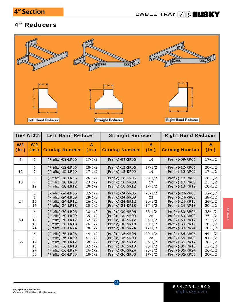
8 6 4 . 2 3 4 . 4 8 0 0m p h u s k y . c o mRev. April 16, 2009 4:50 PM
Copyright 2008 MP Husky. All rights reserved.
CABLE TRAY
27
FIberGlA
SS
4” Reducers
4” Section
Tray Width Left Hand Reducer Straight Reducer Right Hand Reducer
W1(in.)
W2(in.) Catalog Number
A(in.) Catalog Number
A(in.) Catalog Number
A(in.)
9 6 (Prefix)-09-LR06 17-1/2 (Prefix)-09-SR06 16 (Prefix)-09-RR06 17-1/2
1269
(Prefix)-12-LR06(Prefix)-12-LR09
20-1/217-1/2
(Prefix)-12-SR06(Prefix)-12-SR09
17-1/216
(Prefix)-12-RR06(Prefix)-12-RR09
20-1/217-1/2
186912
(Prefix)-18-LR06(Prefix)-18-LR09(Prefix)-18-LR12
26-1/223-1/220-1/2
(Prefix)-18-SR06(Prefix)-18-SR09(Prefix)-18-SR12
20-1/219
17-1/2
(Prefix)-18-RR06(Prefix)-18-RR09(Prefix)-18-RR12
26-1/223-1/220-1/2
24
691218
(Prefix)-24-LR06(Prefix)-24-LR09(Prefix)-24-LR12(Prefix)-24-LR18
32-1/229-1/226-1/220-1/2
(Prefix)-24-SR06(Prefix)-24-SR09(Prefix)-24-SR12(Prefix)-24-SR18
23-1/222
20-1/217-1/2
(Prefix)-24-RR06(Prefix)-24-RR09(Prefix)-24-RR12(Prefix)-24-RR18
32-1/229-1/226-1/220-1/2
30
69121824
(Prefix)-30-LR06(Prefix)-30-LR09(Prefix)-30-LR12(Prefix)-30-LR18(Prefix)-30-LR24
38-1/235-1/232-1/226-1/220-1/2
(Prefix)-30-SR06(Prefix)-30-SR09(Prefix)-30-SR12(Prefix)-30-SR18(Prefix)-30-SR24
26-1/225
23-1/220-1/217-1/2
(Prefix)-30-RR06(Prefix)-30-RR09(Prefix)-30-RR12(Prefix)-30-RR18(Prefix)-30-RR24
38-1/235-1/232-1/226-1/220-1/2
36
6912182430
(Prefix)-36-LR06(Prefix)-36-LR09(Prefix)-36-LR12(Prefix)-36-LR18(Prefix)-36-LR24(Prefix)-36-LR30
44-1/241-1/238-1/232-1/226-1/220-1/2
(Prefix)-36-SR06(Prefix)-36-SR09(Prefix)-36-SR12(Prefix)-36-SR18(Prefix)-36-SR24(Prefix)-36-SR30
29-1/228
26-1/223-1/220-1/217-1/2
(Prefix)-36-RR06(Prefix)-36-RR09(Prefix)-36-RR12(Prefix)-36-RR18(Prefix)-36-RR24(Prefix)-36-RR30
44-1/241-1/238-1/232-1/226-1/220-1/2
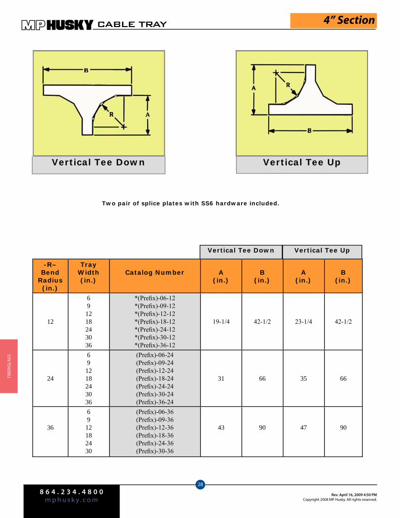
8 6 4 . 2 3 4 . 4 8 0 0m p h u s k y . c o m
Rev. April 16, 2009 4:50 PMCopyright 2008 MP Husky. All rights reserved.
CABLE TRAY
28
FIbe
rGlA
SS
Vertical Tee Down Vertical Tee Up
Two pair of splice plates with SS6 hardware included.
4” Section
Vertical Tee Down Vertical Tee Up
-R– Bend
Radius(in.)
TrayWidth(in.)
Catalog Number A(in.)
B(in.)
A(in.)
B(in.)
12
691218243036
*(Prefix)-06-12*(Prefix)-09-12*(Prefix)-12-12*(Prefix)-18-12*(Prefix)-24-12*(Prefix)-30-12*(Prefix)-36-12
19-1/4 42-1/2 23-1/4 42-1/2
24
691218243036
(Prefix)-06-24(Prefix)-09-24(Prefix)-12-24(Prefix)-18-24(Prefix)-24-24(Prefix)-30-24(Prefix)-36-24
31 66 35 66
36
6912182430
(Prefix)-06-36(Prefix)-09-36(Prefix)-12-36(Prefix)-18-36(Prefix)-24-36(Prefix)-30-36
43 90 47 90
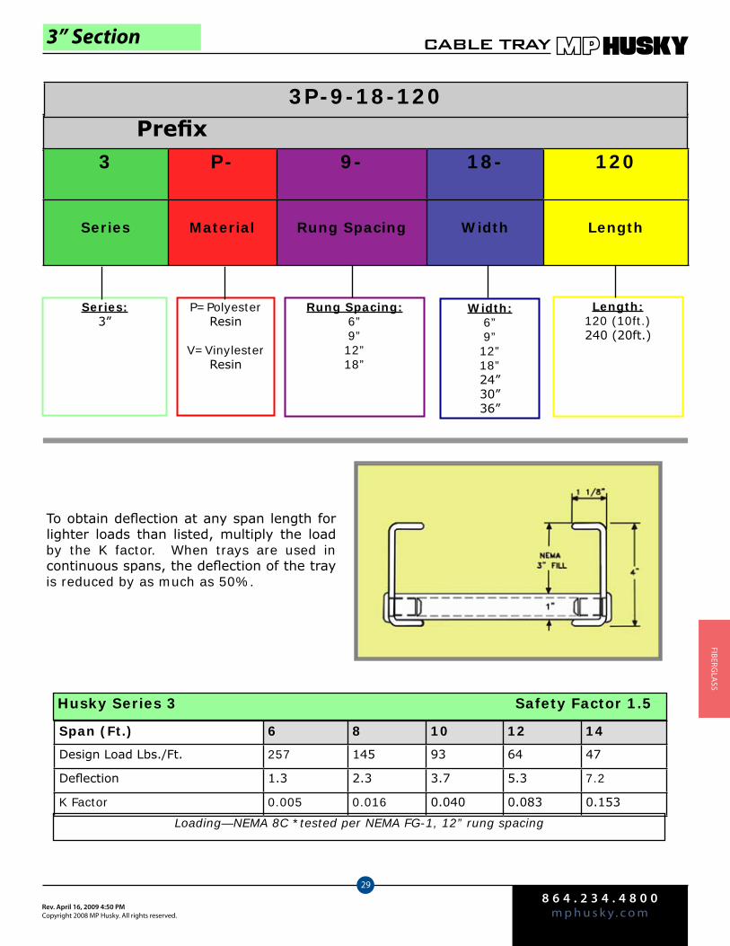
8 6 4 . 2 3 4 . 4 8 0 0m p h u s k y . c o mRev. April 16, 2009 4:50 PM
Copyright 2008 MP Husky. All rights reserved.
CABLE TRAY
29
FIberGlA
SS
3” Section
Series:3”
P=Polyester Resin
V=Vinylester Resin
Rung Spacing:6”9”12”18”
Width:6”9”12”18”24”30”36”
Length:120 (10ft.) 240 (20ft.)
To obtain deflection at any span length for lighter loads than listed, multiply the load by the K factor. When trays are used in continuous spans, the deflection of the tray is reduced by as much as 50%.
Span (Ft.) 6 8 10 12 14
Design Load Lbs./Ft. 257 145 93 64 47
Deflection 1.3 2.3 3.7 5.3 7.2
K Factor 0.005 0.016 0.040 0.083 0.153
Husky Series 3 Safety Factor 1.5
Loading—NEMA 8C *tested per NEMA FG-1, 12” rung spacing
Prefix3P-9-18-120
3 P- 9- 18- 120
Series Material Rung Spacing Width Length
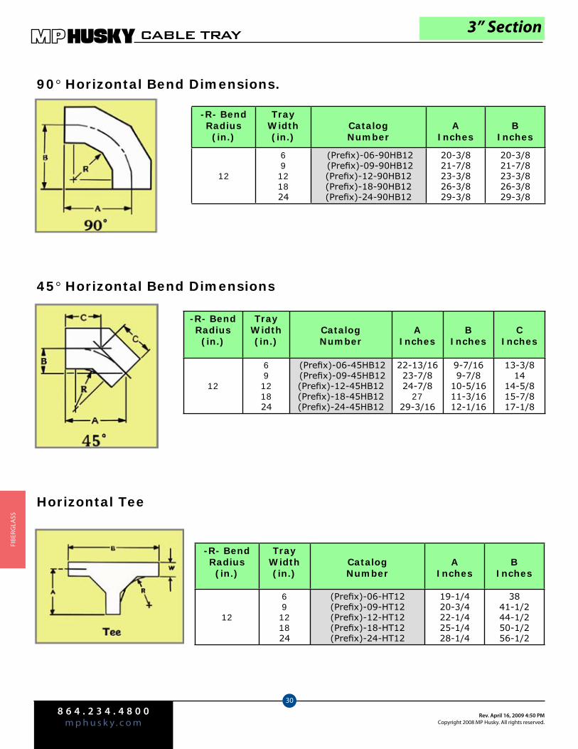
8 6 4 . 2 3 4 . 4 8 0 0m p h u s k y . c o m
Rev. April 16, 2009 4:50 PMCopyright 2008 MP Husky. All rights reserved.
CABLE TRAY
30
FIbe
rGlA
SS
3” Section
90° Horizontal Bend Dimensions.
45° Horizontal Bend Dimensions
-R- BendRadius (in.)
TrayWidth(in.)
CatalogNumber
AInches
BInches
12
69121824
(Prefix)-06-90HB12 (Prefix)-09-90HB12(Prefix)-12-90HB12(Prefix)-18-90HB12(Prefix)-24-90HB12
20-3/821-7/823-3/826-3/829-3/8
20-3/821-7/823-3/826-3/829-3/8
-R- BendRadius (in.)
TrayWidth(in.)
CatalogNumber
AInches
BInches
CInches
12
69121824
(Prefix)-06-45HB12 (Prefix)-09-45HB12(Prefix)-12-45HB12(Prefix)-18-45HB12(Prefix)-24-45HB12
22-13/1623-7/824-7/8
2729-3/16
9-7/169-7/8
10-5/1611-3/1612-1/16
13-3/814
14-5/815-7/817-1/8
-R- BendRadius (in.)
TrayWidth(in.)
CatalogNumber
AInches
BInches
12
69121824
(Prefix)-06-HT12(Prefix)-09-HT12(Prefix)-12-HT12(Prefix)-18-HT12(Prefix)-24-HT12
19-1/420-3/422-1/425-1/428-1/4
3841-1/244-1/250-1/256-1/2
Horizontal Tee
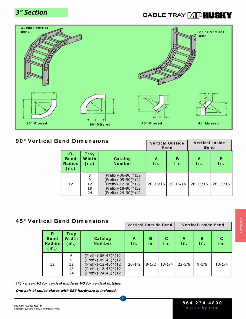
8 6 4 . 2 3 4 . 4 8 0 0m p h u s k y . c o mRev. April 16, 2009 4:50 PM
Copyright 2008 MP Husky. All rights reserved.
CABLE TRAY
31
FIberGlA
SS
3” Section
Vertical Outside Bend
Vertical Inside Bend
90° Vertical Bend Dimensions
45° Vertical Bend DimensionsVertical Outside Bend Vertical Inside Bend
90° Mitered 90° Mitered 45° Mitered 45° Mitered
One pair of splice plates with SS6 hardware is included.
Outside Vertical Bend Inside Vertical
Bend
(*) - insert VI for vertical inside or VO for vertical outside.
-R- Bend
Radius (in.)
TrayWidth(in.)
CatalogNumber
AIn.
BIn.
AIn.
BIn.
12
69121824
(Prefix)-06-90(*)12(Prefix)-09-90(*)12(Prefix)-12-90(*)12(Prefix)-18-90(*)12(Prefix)-24-90(*)12
20-15/16 20-15/16 26-15/16 26-15/16
-R- Bend
Radius (in.)
TrayWidth(in.)
CatalogNumber
AIn.
BIn.
CIn.
AIn.
BIn.
CIn.
12
69121824
(Prefix)-06-45(*)12(Prefix)-09-45(*)12(Prefix)-12-45(*)12(Prefix)-18-45(*)12(Prefix)-24-45(*)12
20-1/2 8-1/2 13-1/4 22-5/8 9-3/8 13-1/4
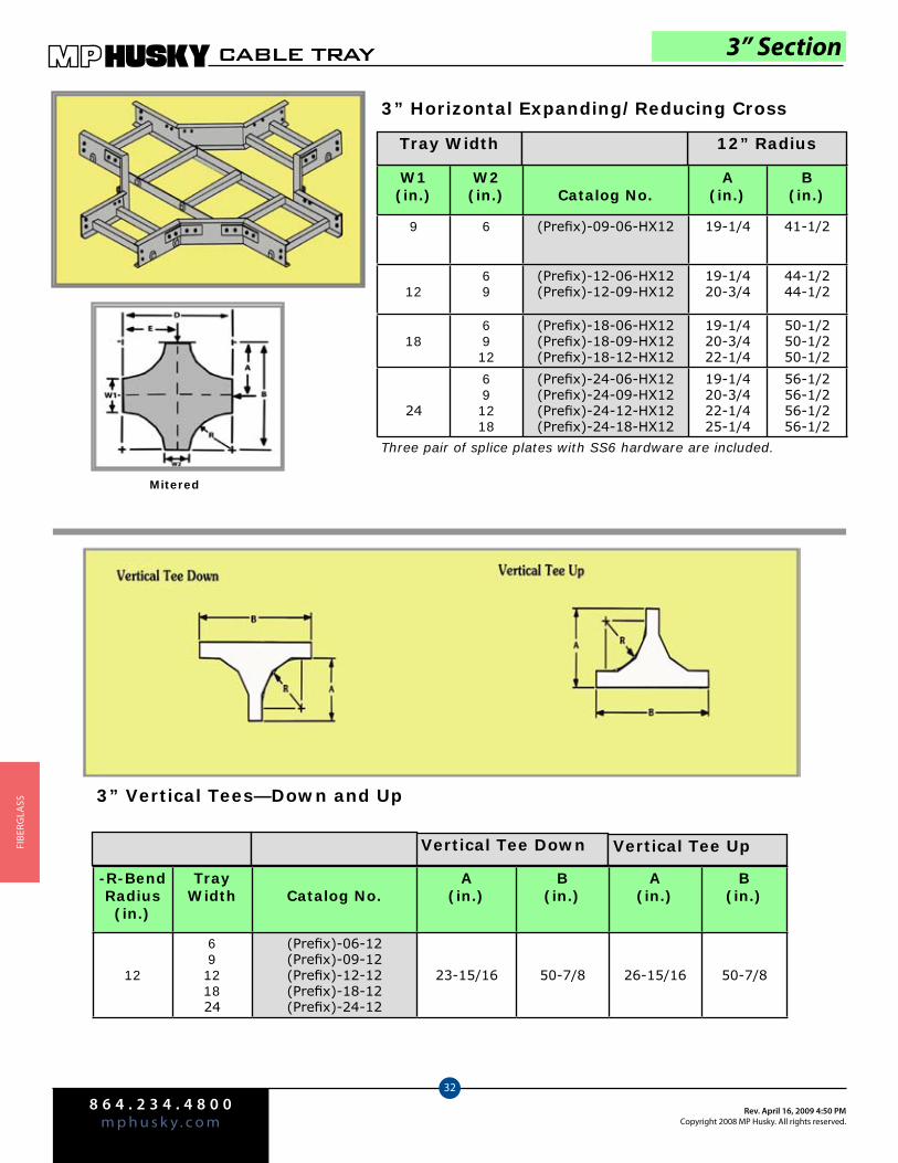
8 6 4 . 2 3 4 . 4 8 0 0m p h u s k y . c o m
Rev. April 16, 2009 4:50 PMCopyright 2008 MP Husky. All rights reserved.
CABLE TRAY
32
FIbe
rGlA
SS
3” Section
W1(in.)
W2(in.) Catalog No.
A(in.)
B(in.)
9 6 (Prefix)-09-06-HX12 19-1/4 41-1/2
1269
(Prefix)-12-06-HX12(Prefix)-12-09-HX12
19-1/420-3/4
44-1/244-1/2
186912
(Prefix)-18-06-HX12(Prefix)-18-09-HX12(Prefix)-18-12-HX12
19-1/420-3/422-1/4
50-1/250-1/250-1/2
24
691218
(Prefix)-24-06-HX12(Prefix)-24-09-HX12(Prefix)-24-12-HX12(Prefix)-24-18-HX12
19-1/420-3/422-1/425-1/4
56-1/256-1/256-1/256-1/2
Tray Width 12” Radius
3” Horizontal Expanding/Reducing Cross
Three pair of splice plates with SS6 hardware are included.
Mitered
-R-BendRadius(in.)
TrayWidth Catalog No.
A(in.)
B(in.)
A(in.)
B(in.)
12
69121824
(Prefix)-06-12(Prefix)-09-12(Prefix)-12-12(Prefix)-18-12(Prefix)-24-12
23-15/16 50-7/8 26-15/16 50-7/8
Vertical Tee Down Vertical Tee Up
3” Vertical Tees—Down and Up
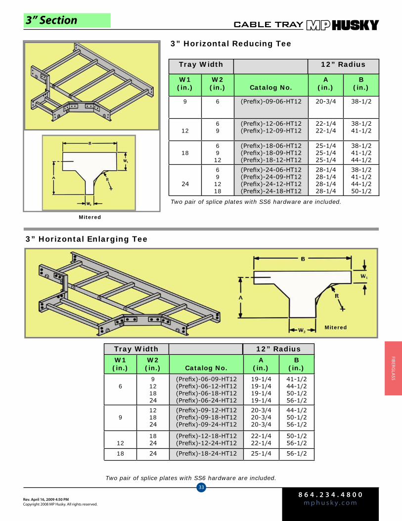
8 6 4 . 2 3 4 . 4 8 0 0m p h u s k y . c o mRev. April 16, 2009 4:50 PM
Copyright 2008 MP Husky. All rights reserved.
CABLE TRAY
33
FIberGlA
SS
3” Section
W1(in.)
W2(in.) Catalog No.
A(in.)
B(in.)
9 6 (Prefix)-09-06-HT12 20-3/4 38-1/2
1269
(Prefix)-12-06-HT12(Prefix)-12-09-HT12
22-1/422-1/4
38-1/241-1/2
186912
(Prefix)-18-06-HT12(Prefix)-18-09-HT12(Prefix)-18-12-HT12
25-1/425-1/425-1/4
38-1/241-1/244-1/2
24
691218
(Prefix)-24-06-HT12(Prefix)-24-09-HT12(Prefix)-24-12-HT12(Prefix)-24-18-HT12
28-1/428-1/428-1/428-1/4
38-1/241-1/244-1/250-1/2
Tray Width 12” Radius
3” Horizontal Reducing Tee
Two pair of splice plates with SS6 hardware are included.
Mitered
Two pair of splice plates with SS6 hardware are included.
Mitered
3” Horizontal Enlarging Tee
Tray Width 12” RadiusW1(in.)
W2(in.) Catalog No.
A(in.)
B(in.)
69121824
(Prefix)-06-09-HT12(Prefix)-06-12-HT12(Prefix)-06-18-HT12(Prefix)-06-24-HT12
19-1/419-1/419-1/419-1/4
41-1/244-1/250-1/256-1/2
9121824
(Prefix)-09-12-HT12(Prefix)-09-18-HT12(Prefix)-09-24-HT12
20-3/420-3/420-3/4
44-1/250-1/256-1/2
121824
(Prefix)-12-18-HT12(Prefix)-12-24-HT12
22-1/422-1/4
50-1/256-1/2
18 24 (Prefix)-18-24-HT12 25-1/4 56-1/2

8 6 4 . 2 3 4 . 4 8 0 0m p h u s k y . c o m
Rev. April 16, 2009 4:50 PMCopyright 2008 MP Husky. All rights reserved.
CABLE TRAY
34
FIbe
rGlA
SS
Tray Width
3” Section
Left Hand Reducer Straight Reducer Right Hand Reducer
W1(in.)
W2(in.) Catalog Number
A(in.) Catalog Number
A(in.) Catalog Number
A(in.)
9 6 (Prefix)-09-LR06 17-1/2 (Prefix)-09-SR06 16 (Prefix)-09-RR06 17-1/2
1269
(Prefix)-12-LR06(Prefix)-12-LR09
20-1/217-1/2
(Prefix)-12-SR06(Prefix)-12-SR09
17-1/216
(Prefix)-12-RR06(Prefix)-12-RR09
20-1/217-1/2
186912
(Prefix)-18-LR06(Prefix)-18-LR09(Prefix)-18-LR12
26-1/223-1/220-1/2
(Prefix)-18-SR06(Prefix)-18-SR09(Prefix)-18-SR12
20-1/219
17-1/2
(Prefix)-18-RR06(Prefix)-18-RR09(Prefix)-18-RR12
26-1/223-1/220-1/2
24
691218
(Prefix)-24-LR06(Prefix)-24-LR09(Prefix)-24-LR12(Prefix)-24-LR18
32-1/229-1/226-1/220-1/2
(Prefix)-24-SR06(Prefix)-24-SR09(Prefix)-24-SR12(Prefix)-24-SR18
23-1/222
20-1/217-1/2
(Prefix)-24-RR06(Prefix)-24-RR09(Prefix)-24-RR12(Prefix)-24-RR18
32-1/229-1/226-1/220-1/2

8 6 4 . 2 3 4 . 4 8 0 0m p h u s k y . c o mRev. April 16, 2009 4:50 PM
Copyright 2008 MP Husky. All rights reserved.
CABLE TRAY
35
FIberGlA
SS
Channel Section
FCC-VP-03-120
Series:Channel
VP=Polyester Resin
VV=Vinylester Resin
Width:2”3”4”6”8”
Length:120 (10ft.) 240 (20ft.)
Note: Splice plates are not included.
Husky Fiberglass Cable Channel Tray is available in Ventilated and Non-Ventilated Design and in Polyester or Vinylester material. The height information is listed below:
2”W—1” High3”W - 1” High
4”W - 1-1/8” High6”W - 1-5/8” High8”W—2-3/16” High
PolyesterVinylester
Width(in.)
Length(ft.)
FCCVP-02-120 FCCVV-02-120 2 10
FCCVP-02-240 FCCVV-02-240 2 20
FCCVP-03-120 FCCVV-03-120 3 10
FCCVP-03-240 FCCVV-03-240 3 20
FCCVP-04-120 FCCVV-04-120 4 10
FCCVP-04-240 FCCVV-04-240 4 20
FCCVP-06-120 FCCVV-06-120 6 10
FCCVP-06-240 FCCVV-06-240 6 20
FCCVP-08-120 FCCVV-08-120 8 10
FCCVP-08-240 FCCVV-08-240 8 20
VENTILATED
PolyesterVinylester
Width(in.)
Length(ft.)
FCCNP-02-120 FCCNV-02-120 2 10
FCCNP-02-240 FCCNV-02-240 2 20
FCCNP-03-120 FCCNV-03-120 3 10
FCCNP-03-240 FCCNV-03-240 3 20
FCCNP-04-120 FCCNV-04-120 4 10
FCCNP-04-240 FCCNV-04-240 4 20
FCCNP-06-120 FCCNV-06-120 6 10
FCCNP-06-240 FCCNV-06-240 6 20
FCCNP-08-120 FCCNV-08-120 8 10
FCCNP-08-240 FCCNV-08-240 8 20
NON-VENTILATED
FCC VP- 03- 120
Series Material Width Length

8 6 4 . 2 3 4 . 4 8 0 0m p h u s k y . c o m
Rev. April 16, 2009 4:50 PMCopyright 2008 MP Husky. All rights reserved.
CABLE TRAY
36
FIbe
rGlA
SS
Cable Channel Fittings
Channel Section
Horizontal 3” Wide 4” Wide 6” Wide 8” Wide
90° FCCNP-03-90HB12 FCCNP-04-90HB12 FCCNP-06-90HB12 FCCNP-08-90HB12
45° FCCNP-03-450HB12 FCCNP-04-45HB12 FCCNP-06-45HB12 FCCNP-08-45HB12
Vertical 3” Wide 4” Wide 6” Wide 8” Wide
90° FCCNP-03-90V*12 FCCNP-04-90V*12 FCCNP-06-90V*12 FCCNP-08-90V*12
45° FCCNP-03-45V*12 FCCNP-04-45V*12 FCCNP-06-45V*12 FCCNP-08-45V*12
One pair of splice plates are included.
One pair of splice plates are included.
Notes: *Insert “O” for Vertical Out or “I” for Vertical In. For vinylester resin, “V” must be added appropriately to the part number in place of “P.
Example: FCCNV-04-90HB12

8 6 4 . 2 3 4 . 4 8 0 0m p h u s k y . c o mRev. April 16, 2009 4:50 PM
Copyright 2008 MP Husky. All rights reserved.
CABLE TRAY
37
FIberGlA
SS
Cable Channel Fittings
Channel Section
Two pairs of splice plates are included.
Three pairs of splice plates are included.
Horizontal Tees
Catalog No. Width (in.)
FCCNP-03-HT12 3
FCCNP-04-HT12 4
FCCNP-06-HT12 6
FCCNP-08-HT12 8
Horizontal Crosses
Catalog No. Width (in.)
FCCNP-03-HX12 3
FCCNP-04-HX12 4
FCCNP-06-HX12 6
FCCNP-08-HX12 8
Horizontal 90° Splice Plates
Catalog #XSS-1901H-SS6
Sold in pairs.
Horizontal 45° Splice Plates
Catalog #XSS-1451H-SS6
Sold in pairs.
Horizontal 30° Splice Plates (pairs)
Catalog #XSS-1301H-SS6
Sold in pairs.
Cable Channel Splice Plates
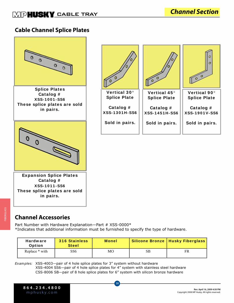
8 6 4 . 2 3 4 . 4 8 0 0m p h u s k y . c o m
Rev. April 16, 2009 4:50 PMCopyright 2008 MP Husky. All rights reserved.
CABLE TRAY
38
FIbe
rGlA
SS
Channel Accessories
Channel Section
Expansion Splice PlatesCatalog #
XSS-1011-SS6These splice plates are sold
in pairs.
Cable Channel Splice Plates
Splice Plates Catalog #
XSS-1001-SS6These splice plates are sold
in pairs.
Vertical 90° Splice Plate
Catalog #XSS-1901V-SS6
Sold in pairs.
Vertical 45° Splice Plate
Catalog #XSS-1451H-SS6
Sold in pairs.
Vertical 30° Splice Plate
Catalog #XSS-1301H-SS6
Sold in pairs.
Part Number with Hardware Explanation—Part # XSS-0000**Indicates that additional information must be furnished to specify the type of hardware.
Examples: XSS-4003—pair of 4 hole splice plates for 3” system without hardware XSS-4004 SS6—pair of 4 hole splice plates for 4” system with stainless steel hardware CSS-8006 SB—pair of 8 hole splice plates for 6” system with silicon bronze hardware
Hardware Option
316 Stainless Steel
Monel Silicone Bronze Husky Fiberglass
Replace * with SS6 MO SB FR
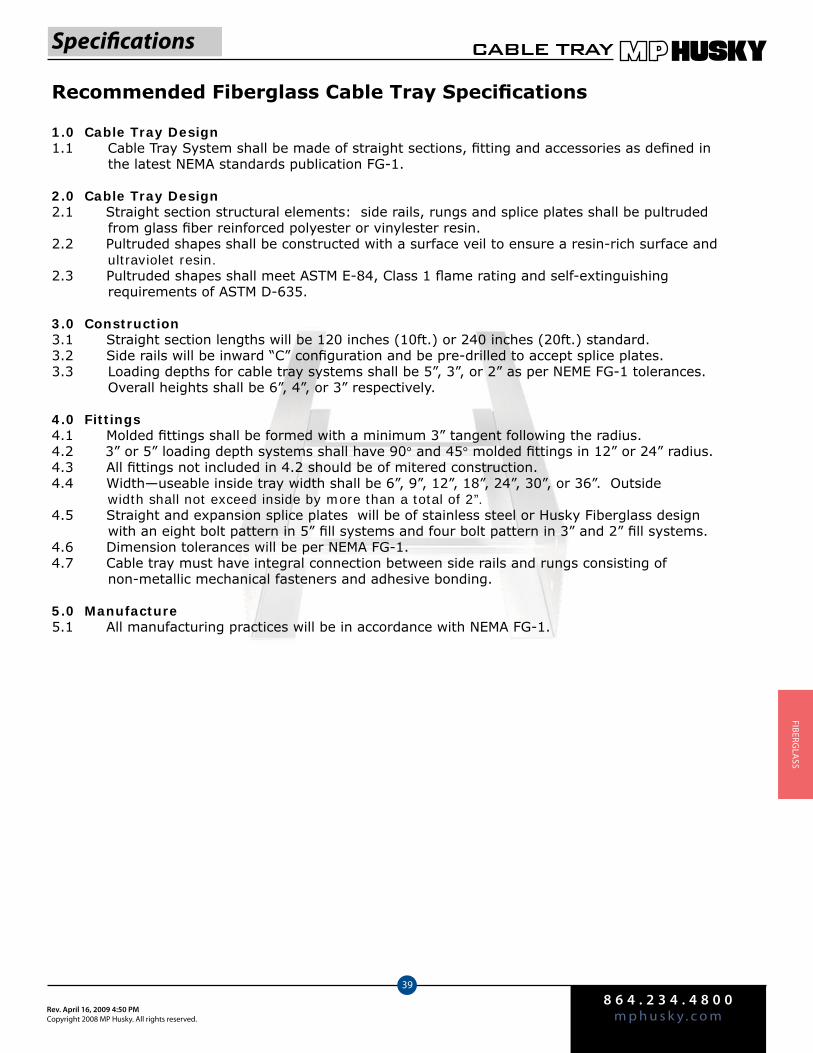
8 6 4 . 2 3 4 . 4 8 0 0m p h u s k y . c o mRev. April 16, 2009 4:50 PM
Copyright 2008 MP Husky. All rights reserved.
CABLE TRAY
39
FIberGlA
SS
Recommended Fiberglass Cable Tray Specifications
1.0 Cable Tray Design1.1 Cable Tray System shall be made of straight sections, fitting and accessories as defined in the latest NEMA standards publication FG-1.
2.0 Cable Tray Design2.1 Straight section structural elements: side rails, rungs and splice plates shall be pultruded from glass fiber reinforced polyester or vinylester resin. 2.2 Pultruded shapes shall be constructed with a surface veil to ensure a resin-rich surface and ultraviolet resin. 2.3 Pultruded shapes shall meet ASTM E-84, Class 1 flame rating and self-extinguishing requirements of ASTM D-635.
3.0 Construction3.1 Straight section lengths will be 120 inches (10ft.) or 240 inches (20ft.) standard. 3.2 Side rails will be inward “C” configuration and be pre-drilled to accept splice plates. 3.3 Loading depths for cable tray systems shall be 5”, 3”, or 2” as per NEME FG-1 tolerances. Overall heights shall be 6”, 4”, or 3” respectively.
4.0 Fittings4.1 Molded fittings shall be formed with a minimum 3” tangent following the radius. 4.2 3” or 5” loading depth systems shall have 90° and 45° molded fittings in 12” or 24” radius. 4.3 All fittings not included in 4.2 should be of mitered construction. 4.4 Width—useable inside tray width shall be 6”, 9”, 12”, 18”, 24”, 30”, or 36”. Outside width shall not exceed inside by more than a total of 2”. 4.5 Straight and expansion splice plates will be of stainless steel or Husky Fiberglass design with an eight bolt pattern in 5” fill systems and four bolt pattern in 3” and 2” fill systems. 4.6 Dimension tolerances will be per NEMA FG-1. 4.7 Cable tray must have integral connection between side rails and rungs consisting of non-metallic mechanical fasteners and adhesive bonding.
5.0 Manufacture5.1 All manufacturing practices will be in accordance with NEMA FG-1.
Specifications
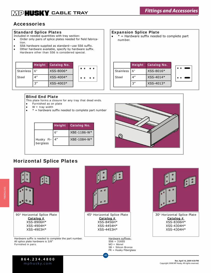
8 6 4 . 2 3 4 . 4 8 0 0m p h u s k y . c o m
Rev. April 16, 2009 4:50 PMCopyright 2008 MP Husky. All rights reserved.
CABLE TRAY
40
FIbe
rGlA
SS
Accessories
Standard Splice PlatesIncluded in needed quantities with tray section:
Order only pairs of splice plates needed for field fabrica- ♦tion.SS6 hardware supplied as standard—use SS6 suffix. ♦Other hardware available, specify by hardware suffix. ♦Hardware other than SS6 is considered special.
Expansion Splice Plate* = Hardware suffix needed to complete part ♦number.
Material Height Catalog No.
Stainless 6” XSS-8006*
Steel 4” XSS-4004*
3” XSS-4003*
Material Height Catalog No.
Stainless 6” XSS-8016*
Steel 4” XSS-4014*
3” XSS-4013*
Blind End PlateThis plate forms a closure for any tray that dead ends.
Furnished as on plate ♦W = tray width ♦* = hardware suffix needed to complete part number ♦
Material Height Catalog No.
6” XBE-1186-W*
Husky Fi-berglass
4” XBE-1084-W*
Fittings and Accessories
45° Horizontal Splice PlateCatalog #
XSS-8456H*XSS-4454H*XSS-4453H*
30° Horizontal Splice PlateCatalog #
XSS-8306H*XSS-4304H*XSS-4304H*
Hardware suffix is needed to complete the part number.All splice plate hardware is 3/8”Furnished in pairs.
Hardware suffixes:SS6 = 316SSMO = MonelSB = Silicon BronzeFR = Husky Fiberglass
90° Horizontal Splice PlateCatalog #
XSS-8906H*XSS-4904H*XSS-4903H*
Horizontal Splice Plates

8 6 4 . 2 3 4 . 4 8 0 0m p h u s k y . c o mRev. April 16, 2009 4:50 PM
Copyright 2008 MP Husky. All rights reserved.
CABLE TRAY
41
FIberGlA
SS
Accessories
Vertical Adjustable Splice PlatesThese plates provide for changes in elevation that do not conform to standard vertical fittings.
Furnished in pairs ♦* Hardware suffix needed to complete part number
Horizontal Adjustable Splice PlatesThese plates provide for changes in the horizontal direc-tion that do not conform to standard fittings
Furnished in pairs ♦* Hardware suffix needed to complete part number
Material Height Catalog No.
Stainless 6” XSS-8026*
Steel 4” XSS-4024*
3” XSS-4023*
Material Height Catalog No.
Stainless 6” XSS-8036*
Steel 4” XSS-4034*
3” XSS-4033*
Step Down PlatesThese splice plates provide for changes in side tail heights.
Furnished in pairs ♦* Hardware suffix needed to complete part number
Material Height Catalog No.
Stainless 6” to 3” XSS-8063*
Steel 6” to 4” XSS-8064*
4” to 3” XSS-4043*
Tray to Box Splice PlatesThese plates are used to attach the end of a tray run to a distribution box or control center.
Furnished in pairs ♦Not available in stainless steel ♦
* Hardware suffix needed to complete part number
Material Height Catalog No.
6” XFP-8056*
FRP 4” XFP-4054*
3” XFP-4053*
90° Vertical Splice PlateCatalog #
XSS-8906V*XSS-4904V*XSS-4903V*
45° Horizontal Splice PlateCatalog #
XSS-8456V*XSS-4454V*XSS-4453V*
30° Horizontal Splice PlateCatalog #
XSS-8306V*XSS-4304V*XSS-4303V*
Vertical Splice Plates
Fittings and Accessories
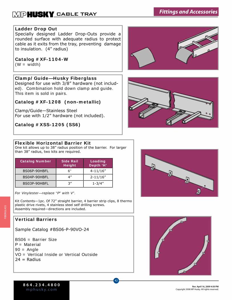
8 6 4 . 2 3 4 . 4 8 0 0m p h u s k y . c o m
Rev. April 16, 2009 4:50 PMCopyright 2008 MP Husky. All rights reserved.
CABLE TRAY
42
FIbe
rGlA
SS
Ladder Drop OutSpecially designed Ladder Drop-Outs provide a rounded surface with adequate radius to protect cable as it exits from the tray, preventing damage to insulation. (4” radius)
Catalog #XF-1104-W(W = width)
Clamp/Guide—Husky FiberglassDesigned for use with 3/8” hardware (not includ-ed). Combination hold down clamp and guide. This item is sold in pairs.
Catalog #XF-1208 (non-metallic)
Clamp/Guide—Stainless SteelFor use with 1/2” hardware (not included).
Catalog #XSS-1205 (SS6)
Flexible Horizontal Barrier KitOne kit allows up to 38” radius position of the barrier. For larger than 38” radius, two kits are required.
For Vinylester—replace “P” with V”.
Kit Contents—1pc. Of 72” straight barrier, 4 barrier strip clips, 8 thermo plastic drive rivets, 4 stainless steel self drilling screws.Assembly required—directions are included.
Catalog Number Side RailHeight
Loading Depth ‘H’
BS06P-90HBFL 6” 4-11/16”
BS04P-90HBFL 4” 2-11/16”
BS03P-90HBFL 3” 1-3/4”
Vertical Barriers
Sample Catalog #BS06-P-90VO-24
BS06 = Barrier SizeP = Material90 = AngleVO = Vertical Inside or Vertical Outside24 = Radius
Fittings and Accessories

8 6 4 . 2 3 4 . 4 8 0 0m p h u s k y . c o mRev. April 16, 2009 4:50 PM
Copyright 2008 MP Husky. All rights reserved.
CABLE TRAY
43
FIberGlA
SS
Resin Seal Kit and Spray Sealant
Brush-On Resin Seal Kit is used to reseal Husky Fiber-glass after field modifications.
Catalog #8-2-SEAL (1 pint)Catalog #8-2-Seal-QT (1 quart)Contents: Resin, Catalyst, Stir Stick, and Applicator. All kits are Vinylester Resin.
Spray Sealant is also used to reseal Husky Fiberglass after field modifications.
Catalog #Clear-121512 fl. oz. spray acrylic
SEALA
NT
Thermo Plastic Drive Rivet
Shipped in packages of 25 pcs.
Catalog #TPDR
Cover1/8” Thick, 120” Long10 ea. #10 stainless, self-drilling screws are provided with each section.
Peaked covers are for straight sections only.W* = insert width of tray.
Catalog # Description
FC-P-W*-120 Flat Polyester
FC-V-W*-120 Flat Vinylester
PC-P-W*120 Peaked Polyester
PC-V-W*-120 Peaked Vinylester
Cover Clamps
Catalog # Side Rail Height
XCC-P-9016 6”
XCC-P-9014 4”
XCC-P-9013 3”
Standard Cover Clamp
Heavy Duty Cover Clamp
For Vinylester, replace “P” with “V” in the catalog number.W* = tray width
Catalog # Side Rail Height
XWC-P-W*-9064 6”
XWC-P-W*-9044 4”
XWC-P-W*-9034 3”
Fittings and Accessories
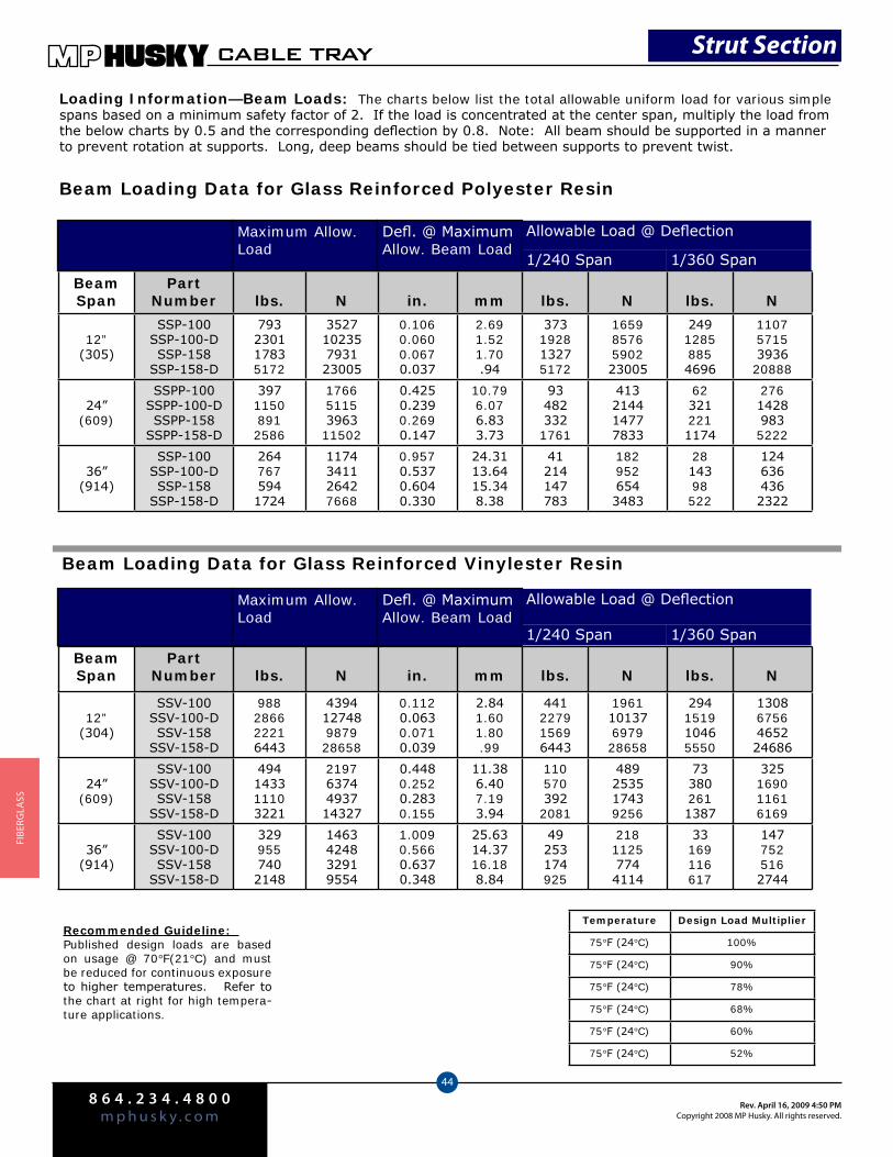
8 6 4 . 2 3 4 . 4 8 0 0m p h u s k y . c o m
Rev. April 16, 2009 4:50 PMCopyright 2008 MP Husky. All rights reserved.
CABLE TRAY
44
FIbe
rGlA
SS
Loading Information—Beam Loads: The charts below list the total allowable uniform load for various simple spans based on a minimum safety factor of 2. If the load is concentrated at the center span, multiply the load from the below charts by 0.5 and the corresponding deflection by 0.8. Note: All beam should be supported in a manner to prevent rotation at supports. Long, deep beams should be tied between supports to prevent twist.
Recommended Guideline: Published design loads are based on usage @ 70°F(21°C) and must be reduced for continuous exposure to higher temperatures. Refer to the chart at right for high tempera-ture applications.
BeamSpan
PartNumber lbs. N in. mm lbs. N lbs. N
12”(305)
SSP-100SSP-100-DSSP-158
SSP-158-D
793230117835172
352710235793123005
0.1060.0600.0670.037
2.691.521.70.94
373192813275172
16598576590223005
24912858854696
11075715393620888
24”(609)
SSPP-100SSPP-100-DSSPP-158
SSPP-158-D
39711508912586
17665115396311502
0.4250.2390.2690.147
10.796.076.833.73
934823321761
413214414777833
623212211174
27614289835222
36”(914)
SSP-100SSP-100-DSSP-158
SSP-158-D
2647675941724
1174341126427668
0.9570.5370.6040.330
24.3113.6415.348.38
41214147783
1829526543483
2814398522
1246364362322
Maximum Allow. Load
Defl. @ MaximumAllow. Beam Load
1/240 Span 1/360 Span
Allowable Load @ Deflection
Beam Loading Data for Glass Reinforced Polyester Resin
BeamSpan
PartNumber lbs. N in. mm lbs. N lbs. N
12”(304)
SSV-100SSV-100-DSSV-158
SSV-158-D
988286622216443
439412748987928658
0.1120.0630.0710.039
2.841.601.80.99
441227915696443
196110137697928658
294151910465550
13086756465224686
24”(609)
SSV-100SSV-100-DSSV-158
SSV-158-D
494143311103221
21976374493714327
0.4480.2520.2830.155
11.386.407.193.94
1105703922081
489253517439256
733802611387
325169011616169
36”(914)
SSV-100SSV-100-DSSV-158
SSV-158-D
3299557402148
1463424832919554
1.0090.5660.6370.348
25.6314.3716.188.84
49253174925
21811257744114
33169116617
1477525162744
Maximum Allow. Load
Defl. @ MaximumAllow. Beam Load
1/240 Span 1/360 Span
Allowable Load @ Deflection
Beam Loading Data for Glass Reinforced Vinylester Resin
Temperature Design Load Multiplier
75°F (24°C) 100%
75°F (24°C) 90%
75°F (24°C) 78%
75°F (24°C) 68%
75°F (24°C) 60%
75°F (24°C) 52%
Strut Section

8 6 4 . 2 3 4 . 4 8 0 0m p h u s k y . c o mRev. April 16, 2009 4:50 PM
Copyright 2008 MP Husky. All rights reserved.
CABLE TRAY
45
FIberGlA
SS
Channels, Combinations and Hole Patterns
Part # Material/Resin Description Color
Wtlbs./ft.
Wtkg/ft.
SSP-100 Polyester Solid Back Gray .47 .70
SSV-100 Vinylester Solid Back Beige .47 .70
SSP-100-D Polyester Solid Back Gray .86 1.28
SSV-100-D Vinylester Solid Back Beige .86 1.28
Part # Material/Resin Description Color
Wtlbs./ft.
Wtkg/ft.
SSP-158 Polyester Solid Back Gray .63 .94
SSV-158 Vinylester Solid Back Beige .63 .94
SSP-158-D Polyester Solid Back Gray 1.17 1.75
SSP-158-D Vinylester Solid Back Beige 1.17 1.75
Part # Material/Resin Description Color
Wtlbs./ft.
Wtkg/ft.
SSP-100-H Polyester Holes in Back Gray .45 .67
SSV-100-H Vinylester Holes in Back Beige .45 .67
SSP-158-H Polyester Holes in Back Gray .61 .91
SSV-158-H Vinylester Holes in Back Beige .61 .91
Part # Material/Resin Description Color
Wtlbs./ft.
Wtkg/ft.
SSP-100-S Polyester Slots in Back Gray .46 .69
SSV-100-S Vinylester Slots in Back Beige .46 .69
SSP-158-S Polyester Slots in Back Gray .62 .93
SSV-158-S Vinylester Slots in Back Beige .62 .93
Part # Material/Resin Description Color
Wtlbs./ft.
Wtkg/ft.
SSP-158-I Polyester Conc. Insert Gray 1.04 1.55
SSV-158-I Vinylester Conc. Insert Beige 1.04 1.55
Strut Section
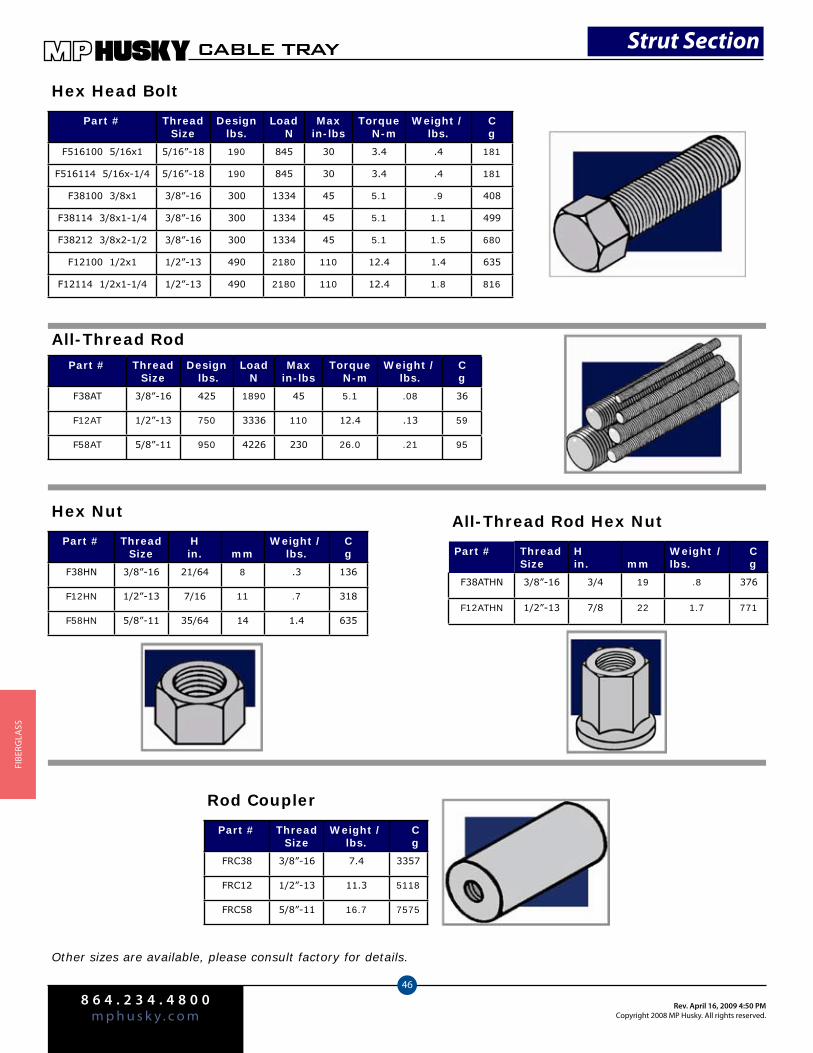
8 6 4 . 2 3 4 . 4 8 0 0m p h u s k y . c o m
Rev. April 16, 2009 4:50 PMCopyright 2008 MP Husky. All rights reserved.
CABLE TRAY
46
FIbe
rGlA
SS
Part # ThreadSize
Designlbs.
Load N
Maxin-lbs
Torque N-m
Weight /lbs.
Cg
F516100 5/16x1 5/16”-18 190 845 30 3.4 .4 181
F516114 5/16x-1/4 5/16”-18 190 845 30 3.4 .4 181
F38100 3/8x1 3/8”-16 300 1334 45 5.1 .9 408
F38114 3/8x1-1/4 3/8”-16 300 1334 45 5.1 1.1 499
F38212 3/8x2-1/2 3/8”-16 300 1334 45 5.1 1.5 680
F12100 1/2x1 1/2”-13 490 2180 110 12.4 1.4 635
F12114 1/2x1-1/4 1/2”-13 490 2180 110 12.4 1.8 816
Part # ThreadSize
Design lbs.
LoadN
Maxin-lbs
Torque N-m
Weight /lbs.
Cg
F38AT 3/8”-16 425 1890 45 5.1 .08 36
F12AT 1/2”-13 750 3336 110 12.4 .13 59
F58AT 5/8”-11 950 4226 230 26.0 .21 95
Hex Head Bolt
All-Thread Rod
Part # ThreadSize
Hin. mm
Weight /lbs.
Cg
F38HN 3/8”-16 21/64 8 .3 136
F12HN 1/2”-13 7/16 11 .7 318
F58HN 5/8”-11 35/64 14 1.4 635
Hex Nut
Other sizes are available, please consult factory for details.
All-Thread Rod Hex Nut
Part # ThreadSize
Hin. mm
Weight /lbs.
C g
F38ATHN 3/8”-16 3/4 19 .8 376
F12ATHN 1/2”-13 7/8 22 1.7 771
Part # ThreadSize
Weight /lbs.
C g
FRC38 3/8”-16 7.4 3357
FRC12 1/2”-13 11.3 5118
FRC58 5/8”-11 16.7 7575
Rod Coupler
Strut Section
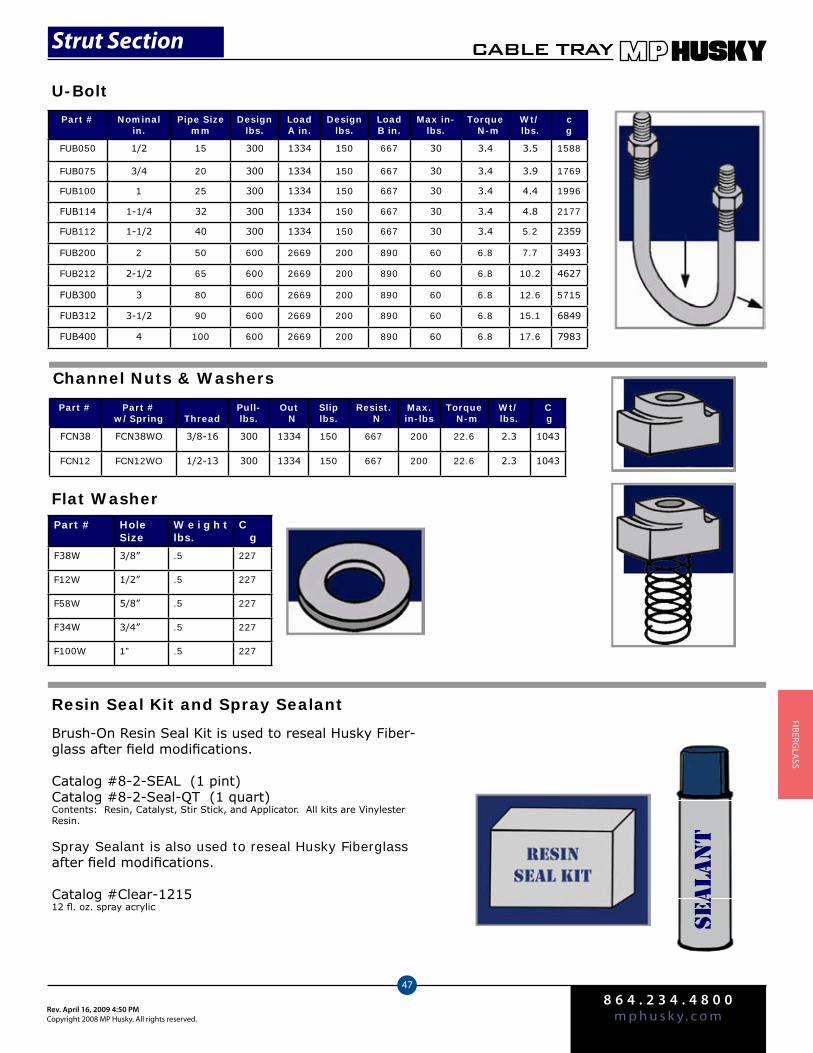
8 6 4 . 2 3 4 . 4 8 0 0m p h u s k y . c o mRev. April 16, 2009 4:50 PM
Copyright 2008 MP Husky. All rights reserved.
CABLE TRAY
47
FIberGlA
SS
U-Bolt
Channel Nuts & Washers
Part # HoleSize
W e i g h t lbs.
C g
F38W 3/8” .5 227
F12W 1/2” .5 227
F58W 5/8” .5 227
F34W 3/4” .5 227
F100W 1” .5 227
Flat Washer
Part # Part #w/Spring Thread
Pull-lbs.
Out N
Sliplbs.
Resist. N
Max.in-lbs
Torque N-m
Wt/lbs.
C g
FCN38 FCN38WO 3/8-16 300 1334 150 667 200 22.6 2.3 1043
FCN12 FCN12WO 1/2-13 300 1334 150 667 200 22.6 2.3 1043
Resin Seal Kit and Spray Sealant
Brush-On Resin Seal Kit is used to reseal Husky Fiber-glass after field modifications.
Catalog #8-2-SEAL (1 pint)Catalog #8-2-Seal-QT (1 quart)Contents: Resin, Catalyst, Stir Stick, and Applicator. All kits are Vinylester Resin.
Spray Sealant is also used to reseal Husky Fiberglass after field modifications.
Catalog #Clear-121512 fl. oz. spray acrylic
SEALA
NT
Strut Section
Part # Nominalin.
Pipe Sizemm
Designlbs.
Load A in.
Designlbs.
Load B in.
Max in-lbs.
Torque N-m
Wt/lbs.
cg
FUB050 1/2 15 300 1334 150 667 30 3.4 3.5 1588
FUB075 3/4 20 300 1334 150 667 30 3.4 3.9 1769
FUB100 1 25 300 1334 150 667 30 3.4 4.4 1996
FUB114 1-1/4 32 300 1334 150 667 30 3.4 4.8 2177
FUB112 1-1/2 40 300 1334 150 667 30 3.4 5.2 2359
FUB200 2 50 600 2669 200 890 60 6.8 7.7 3493
FUB212 2-1/2 65 600 2669 200 890 60 6.8 10.2 4627
FUB300 3 80 600 2669 200 890 60 6.8 12.6 5715
FUB312 3-1/2 90 600 2669 200 890 60 6.8 15.1 6849
FUB400 4 100 600 2669 200 890 60 6.8 17.6 7983

8 6 4 . 2 3 4 . 4 8 0 0m p h u s k y . c o m
Rev. April 16, 2009 4:50 PMCopyright 2008 MP Husky. All rights reserved.
CABLE TRAY
48
FIbe
rGlA
SS
Safety factor of 3 on Design Load. Not recommended for vertical installation without additional supports.
Safety factor of 3 on Design Load. Not recommended for vertical installation without additional supports.
Part # Nominalin.
Pipe Sizemm
Pipelbs.
O.D. Rangemm
Designlbs.
Load N
Max.in-lbs
Torque N-m
SAPC050 1/2 to 3/4 15,20 75-1.05 19-28 75 .33 15 1.69
SAPC100 1-1 to 1/2 25,40 1.05-1.90 29-48 150 .67 22 2.48
SAPC112 1-1/2 to 2-1/2 40,65 1.90-2.87 48-73 150 .67 22 2.48
SAPC212 2-1/2 to 3-1/2 65,90 2.87-4.0 73-101 150 .67 22 2.48
Adjustable Pipe Clamp
Rigid Pipe Clamp
Conduit Swivel Clamp
Part # Nominal in.
Pipe Size mm
Designlbs.
Load N
Max.in-lbs
Torque N-m
SRPC050 1/2 15 300 1.33 10 1.13
SRPC075 3/4 20 300 1.33 10 1.13
SRPC100 1 25 300 1.33 10 1.13
SRPC114 1-1/4 32 300 1.33 10 1.13
SRPC112 1-1/2 40 300 1.33 10 1.13
SRPC200 2 50 300 1.33 10 1.13
SRPC212 2-1/2 65 300 1.33 10 1.13
SRPC300 3 80 300 1.33 10 1.13
SRPC312 3-1/2 90 300 1.33 10 1.13
SRPC400 4 100 300 1.33 10 1.13
Cable Tray Designation (CTD) Required. Example: 6CP, 4PPipe clamps are a separate order item.
Catalog #SCSC-(CTD)
Strut Section
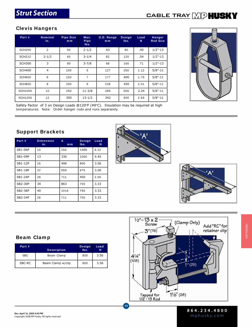
8 6 4 . 2 3 4 . 4 8 0 0m p h u s k y . c o mRev. April 16, 2009 4:50 PM
Copyright 2008 MP Husky. All rights reserved.
CABLE TRAY
49
FIberGlA
SS
Part # Nominalin.
Pipe Size mm
Max. Pipelbs.
O.D. Rangemm
Designlbs.
Load N
HangerRod Size
SCH200 2 50 2-1/2 63 90 .40 1/2”-13
SCH212 2-1/2 65 3-1/4 82 120 .54 1/2”-13
SCH300 3 80 3-7/8 98 160 .71 1/2”-13
SCH400 4 100 5 127 250 1.12 5/8”-11
SCH600 6 150 7 177 400 1.79 5/8”-11
SCH800 8 200 9 228 450 2.01 5/8”-11
SCH1000 10 250 11-3/8 289 500 2.24 5/8”-11
SCH1200 12 300 13-1/2 342 600 2.69 5/8”-11
Clevis Hangers
Support Brackets
Safety Factor of 3 on Design Loads @120°F (49°C). Insulation may be required at high temperatures. Note: Order hanger rods and nuts separately.
Part # Dimension in.
A mm
Designlbs.
Load N
SB1-06P 10 250 1400 6.22
SB1-09P 13 330 1000 4.45
SB1-12P 16 406 800 3.56
SB1-18P 22 559 675 3.00
SB1-24P 28 711 450 2.00
SB2-30P 34 863 750 3.33
SB2-36P 40 1016 750 3.33
SB2-24P 28 711 750 3.33
Beam Clamp
Part #Description
Designlbs.
Load N
SBC Beam Clamp 800 3.56
SBC-RC Beam Clamp w/clip 800 3.56
Strut Section
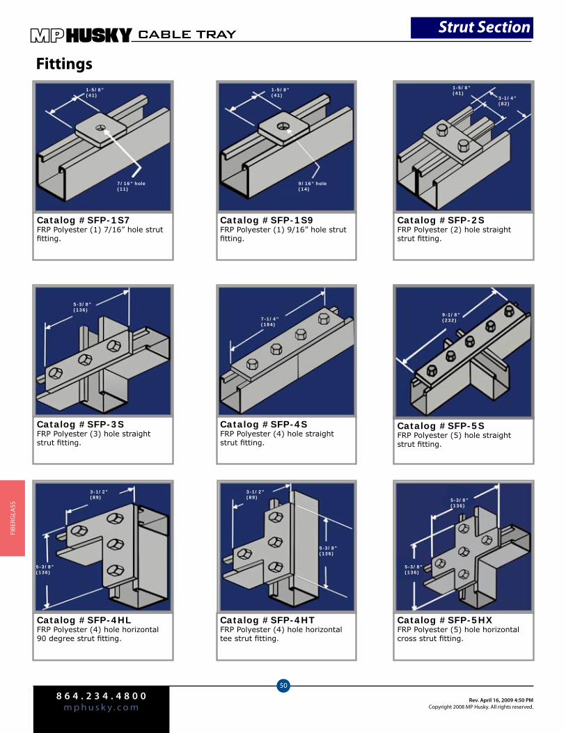
8 6 4 . 2 3 4 . 4 8 0 0m p h u s k y . c o m
Rev. April 16, 2009 4:50 PMCopyright 2008 MP Husky. All rights reserved.
CABLE TRAY
50
FIbe
rGlA
SS
Fittings
Catalog #SFP-1S7FRP Polyester (1) 7/16” hole strut fitting.
Catalog #SFP-1S9FRP Polyester (1) 9/16” hole strut fitting.
Catalog #SFP-2SFRP Polyester (2) hole straight strut fitting.
Catalog #SFP-3SFRP Polyester (3) hole straight strut fitting.
Catalog #SFP-4SFRP Polyester (4) hole straight strut fitting.
Catalog #SFP-5SFRP Polyester (5) hole straight strut fitting.
Catalog #SFP-4HLFRP Polyester (4) hole horizontal 90 degree strut fitting.
Catalog #SFP-4HTFRP Polyester (4) hole horizontal tee strut fitting.
Catalog #SFP-5HXFRP Polyester (5) hole horizontal cross strut fitting.
1-5/8”(41)
7/16” hole(11)
1-5/8”(41)
9/16” hole(14)
1-5/8”(41)
3-1/4”(82)
9-1/8”(232)7-1/4”
(184)
5-3/8”(136)
3-1/2”(89)
5-3/8”(136)
3-1/2”(89)
5-3/8”(136)
5-3/8”(136)
5-3/8”(136)
Strut Section
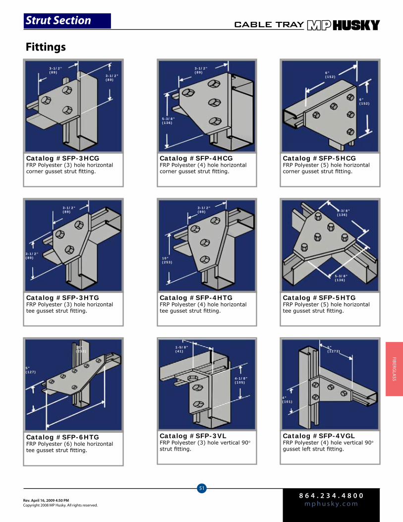
8 6 4 . 2 3 4 . 4 8 0 0m p h u s k y . c o mRev. April 16, 2009 4:50 PM
Copyright 2008 MP Husky. All rights reserved.
CABLE TRAY
51
FIberGlA
SS
Fittings
Catalog #SFP-3HCGFRP Polyester (3) hole horizontal corner gusset strut fitting.
Catalog #SFP-4HCGFRP Polyester (4) hole horizontal corner gusset strut fitting.
Catalog #SFP-5HCGFRP Polyester (5) hole horizontal corner gusset strut fitting.
Catalog #SFP-3HTGFRP Polyester (3) hole horizontal tee gusset strut fitting.
Catalog #SFP-4HTGFRP Polyester (4) hole horizontal tee gusset strut fitting.
Catalog #SFP-5HTGFRP Polyester (5) hole horizontal tee gusset strut fitting.
Catalog #SFP-6HTGFRP Polyester (6) hole horizontal tee gusset strut fitting.
Catalog #SFP-3VLFRP Polyester (3) hole vertical 90° strut fitting.
Catalog #SFP-4VGLFRP Polyester (4) hole vertical 90° gusset left strut fitting.
3-1/2”(89)
3-1/2”(89)
3-1/2”(89)
5-3/8”(136)
6”(152)
6”(152)
3-1/2”(89)
3-1/2”(89)
3-1/2”(89)
10”(253)
5-3/8”(136)
5-3/8”(136)
5”(127)
4-1/8”(105)
10”(253)
1-5/8”(41)
5”(1273)
4”(101)
Strut Section
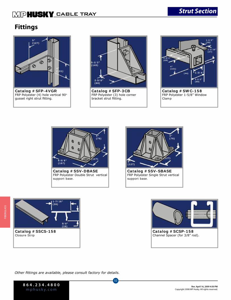
8 6 4 . 2 3 4 . 4 8 0 0m p h u s k y . c o m
Rev. April 16, 2009 4:50 PMCopyright 2008 MP Husky. All rights reserved.
CABLE TRAY
52
FIbe
rGlA
SS
Fittings
Catalog #SFP-4VGRFRP Polyester (4) hole vertical 90° gusset right strut fitting.
Catalog #SFP-3CBFRP Polyester (3) hole corner bracket strut fitting.
Catalog #SWC-158FRP Polyester 1-5/8” Window Clamp
Catalog #SSV-DBASEFRP Polyester Double Strut vertical support base.
Catalog #SSV-SBASEFRP Polyester Single Strut vertical support base.
Catalog #SSCS-158Closure Strip
Catalog #SCSP-158Channel Spacer (for 3/8” rod).
Other fittings are available, please consult factory for details.
1-7/16”(36)
5/8”(16)
3”(76)
5”(127)
6-5/8”(167)
3”(76)
5”(127)
5”(127)
5”(127)
4”(101)
5-1/2”(140)
2-5/8”(66)
4”(101)
2-3/4”(69)
(44) 1-3/4”
3-1/2”(89)
1-1/16”(27)
1-1/2”(38)
Strut Section

204 Old Piedmont HwyGreenville, SC 29605
864-234-4800 (ph)864-234-4822 (fax)
mphusky.com