comparative study on the effectiveness of shunt facts devices (svc ... · fig. 1. schematic diagram...
TRANSCRIPT
Comparative Study on the Effectiveness of Shunt
Facts Devices (SVC, STATCOM) and Series Facts
Device (TCSC) for the Enhancement of Transient
Stability of Two Area Multi Machine Power
System
Md. Shakil Haque*, Md. Tariqur Rahman, Md. Rezaul Karim, Md. Mahbubur Rahman Department of EEE,
University of Dhaka (Mymensingh Engineering College)
Mymensingh, Bangladesh
Abstract—Transient stability is important from the point of
view maintaining system security that is the incidence of a fault
should not lead to tripping of generating unit due to loss of
synchronism and the possibility of a cascaded outage leading to
system black out. FACTS devices are capable of controlling the
network condition in a very fast manner by reactive power
management and can be exploited to improve the transient
stability of a system. The purpose of this paper is to deal with
the comparative performance of SVC, STATCOM and TCSC
for the transient stability improvement of two area multi
machine power system. Simulations are carried out in
MATLAB/SIMULINK environment for two area multi machine
system modeling with shunt and series FACTS devices to
analyze the transient stability improvement of the system.
Among the shunt controllers, the STATCOM performs better
than SVC. But the TCSC is more effective than the shunt
controllers, as it offers greater controllability of the power flow
in the line and also increases the transfer limits or to improve
the transient stability.
Keywords—Transient stability; FACTS devices; SVC;
STATCOM; TCSC; MATLAB/SIMULINK.
I. INTRODUCTION
In recent years, power demand has increased substantially while the expansion of power generation and transmission has been severely limited [1] due to limited resources and environmental restrictions. Now, more than ever, advanced technologies are vital for the reliable and secure operation of power systems. Better utilization of the existing power system is provided through the application of advanced control technologies recent development of power electronics introduces the employ of FACTS controllers in power systems. FACTS controllers are capable of controlling the network condition in a very fast manner and this feature of FACTS can be oppressed to improve the voltage stability, and steady state and transient stabilities of a complex power system [2]. The availability of Flexible AC Transmission System (FACTS) controllers [3], such as Static Var Compensators (SVC), Thyristor Control Series Compensators (TCSC), Static
Synchronous Compensators (STATCOM), and Unified Power Flow Controller (UPFC), has led their use to damp inter-area oscillations. SVC is a first generation FACTS device that is used to maintain the voltage at a particular bus by means of reactive power compensation. SVC is also used to dampen power swings, improve transient stability, and reduce system losses by optimized reactive power control [4]-[5]. STATCOM is a power electronic based device that has capability of controlling the power flow through the line by injecting appropriate reactive power to power system. Amongst the available FACTS [6] devices for transient stability enhancement, the TCSC is the most versatile one. The TCSC controller can be designed to control the power flow, to increase the transfer limits or to improve the transient stability. This paper aims to explain the improvement of transient stability of a two-area power system with a TCSC. A Matlab/Simulink model is developed for a two-area power system with a TCSC. The performance of TCSC is compared with other FACTS devices such as SVC and STATCOM respectively. From the simulation results, it is inferred that TCSC is an effective FACTS device for transient stability improvement.
II. THEORY
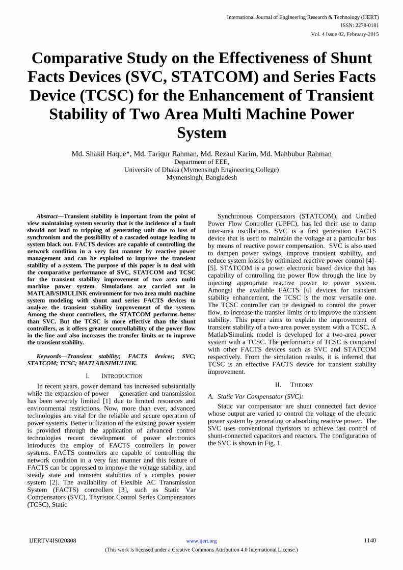
A. Static Var Compensator (SVC):
Static var compensator are shunt connected fact device whose output are varied to control the voltage of the electric power system by generating or absorbing reactive power. The SVC uses conventional thyristors to achieve fast control of shunt-connected capacitors and reactors. The configuration of the SVC is shown in Fig. 1.
International Journal of Engineering Research & Technology (IJERT)
ISSN: 2278-0181
www.ijert.orgIJERTV4IS020808
(This work is licensed under a Creative Commons Attribution 4.0 International License.)
Vol. 4 Issue 02, February-2015
1140
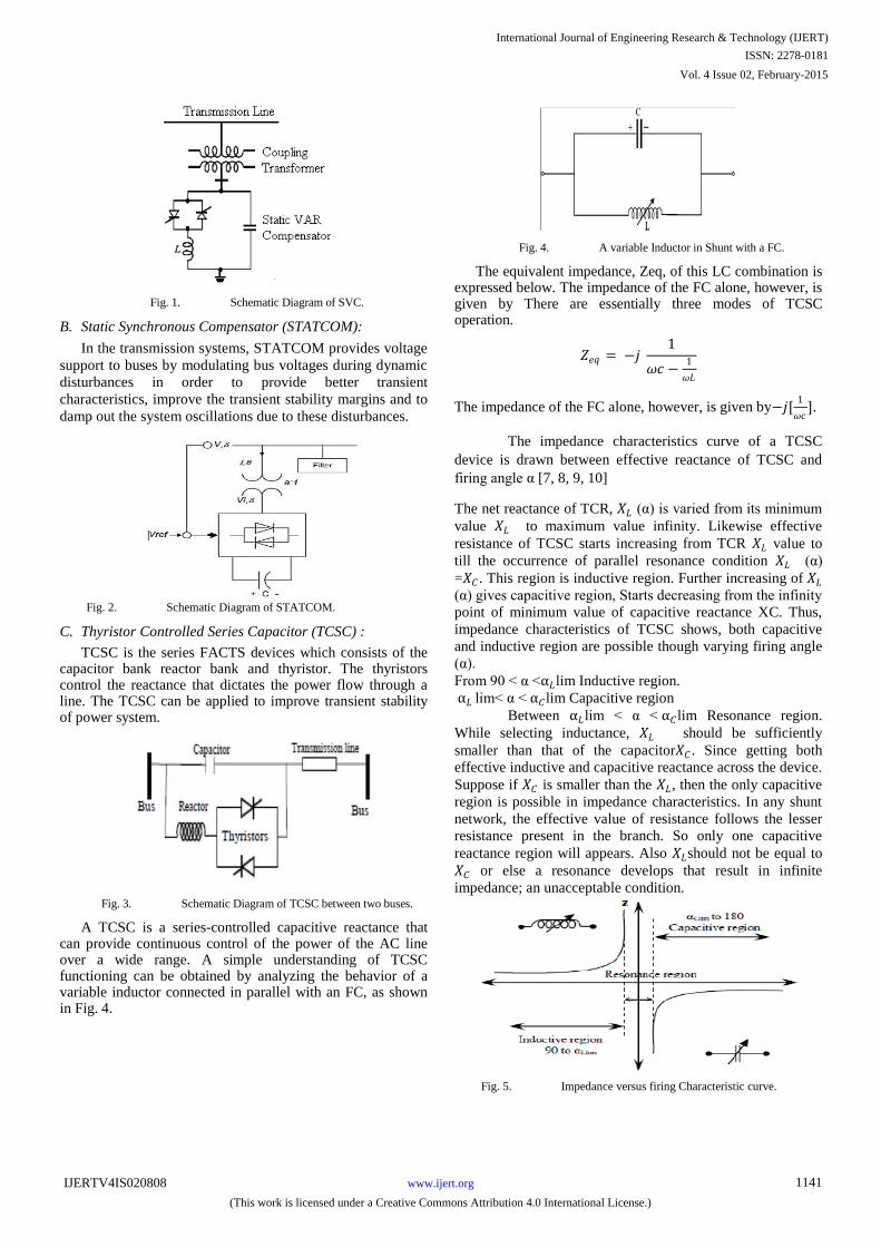
Fig. 1. Schematic Diagram of SVC.
B. Static Synchronous Compensator (STATCOM):
In the transmission systems, STATCOM provides voltage
support to buses by modulating bus voltages during dynamic
disturbances in order to provide better transient
characteristics, improve the transient stability margins and to
damp out the system oscillations due to these disturbances.
Fig. 2. Schematic Diagram of STATCOM.
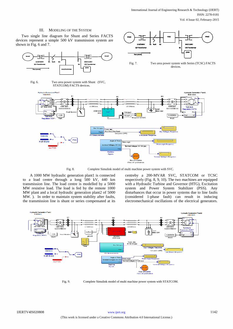
C. Thyristor Controlled Series Capacitor (TCSC) :
TCSC is the series FACTS devices which consists of the capacitor bank reactor bank and thyristor. The thyristors control the reactance that dictates the power flow through a line. The TCSC can be applied to improve transient stability of power system.
Fig. 3. Schematic Diagram of TCSC between two buses.
A TCSC is a series-controlled capacitive reactance that can provide continuous control of the power of the AC line over a wide range. A simple understanding of TCSC functioning can be obtained by analyzing the behavior of a variable inductor connected in parallel with an FC, as shown in Fig. 4.
Fig. 4. A variable Inductor in Shunt with a FC.
The equivalent impedance, Zeq, of this LC combination is expressed below. The impedance of the FC alone, however, is given by There are essentially three modes of TCSC operation.
𝑍𝑒𝑞 = −𝑗 1
𝜔𝑐 −1
𝜔𝐿
The impedance of the FC alone, however, is given by−𝑗[1
𝜔𝑐].
The impedance characteristics curve of a TCSC
device is drawn between effective reactance of TCSC and
firing angle α [7, 8, 9, 10]
The net reactance of TCR, 𝑋𝐿 (α) is varied from its minimum
value 𝑋𝐿 to maximum value infinity. Likewise effective
resistance of TCSC starts increasing from TCR 𝑋𝐿 value to
till the occurrence of parallel resonance condition 𝑋𝐿 (α)
=𝑋𝐶 . This region is inductive region. Further increasing of 𝑋𝐿
(α) gives capacitive region, Starts decreasing from the infinity
point of minimum value of capacitive reactance XC. Thus,
impedance characteristics of TCSC shows, both capacitive
and inductive region are possible though varying firing angle
(α).
From 90 < α <α𝐿lim Inductive region.
α𝐿 lim< α < α𝐶lim Capacitive region
Between α𝐿lim < α < α𝐶lim Resonance region.
While selecting inductance, 𝑋𝐿 should be sufficiently
smaller than that of the capacitor𝑋𝐶 . Since getting both
effective inductive and capacitive reactance across the device.
Suppose if 𝑋𝐶 is smaller than the 𝑋𝐿, then the only capacitive
region is possible in impedance characteristics. In any shunt
network, the effective value of resistance follows the lesser
resistance present in the branch. So only one capacitive
reactance region will appears. Also 𝑋𝐿should not be equal to
𝑋𝐶 or else a resonance develops that result in infinite
impedance; an unacceptable condition.
Fig. 5. Impedance versus firing Characteristic curve.
International Journal of Engineering Research & Technology (IJERT)
ISSN: 2278-0181
www.ijert.orgIJERTV4IS020808
(This work is licensed under a Creative Commons Attribution 4.0 International License.)
Vol. 4 Issue 02, February-2015
1141
III. MODELING OF THE SYSTEM
Two single line diagram for Shunt and Series FACTS devices represent a simple 500 kV transmission system are shown in Fig. 6 and 7.
Fig. 6. Two area power system with Shunt (SVC, STATCOM) FACTS devices.
Fig. 7. Two area power system with Series (TCSC) FACTS devices.
Fig. 8. Complete Simulink model of multi machine power system with SVC.
A 1000 MW hydraulic generation plant1 is connected to a load centre through a long 500 kV, 440 km transmission line. The load centre is modelled by a 5000 MW resistive load. The load is fed by the remote 1000 MW plant and a local hydraulic generation plant2 of 5000 MW. ). In order to maintain system stability after faults, the transmission line is shunt or series compensated at its
centreby a 200-MVAR SVC, STATCOM or TCSC respectively (Fig. 8, 9, 10). The two machines are equipped with a Hydraulic Turbine and Governor (HTG), Excitation system and Power System Stabilizer (PSS). Any disturbances that occur in power systems due to line faults (considered 1-phase fault) can result in inducing electromechanical oscillations of the electrical generators.
Fig. 9. Complete Simulink model of multi machine power system with STATCOM.
International Journal of Engineering Research & Technology (IJERT)
ISSN: 2278-0181
www.ijert.orgIJERTV4IS020808
(This work is licensed under a Creative Commons Attribution 4.0 International License.)
Vol. 4 Issue 02, February-2015
1142
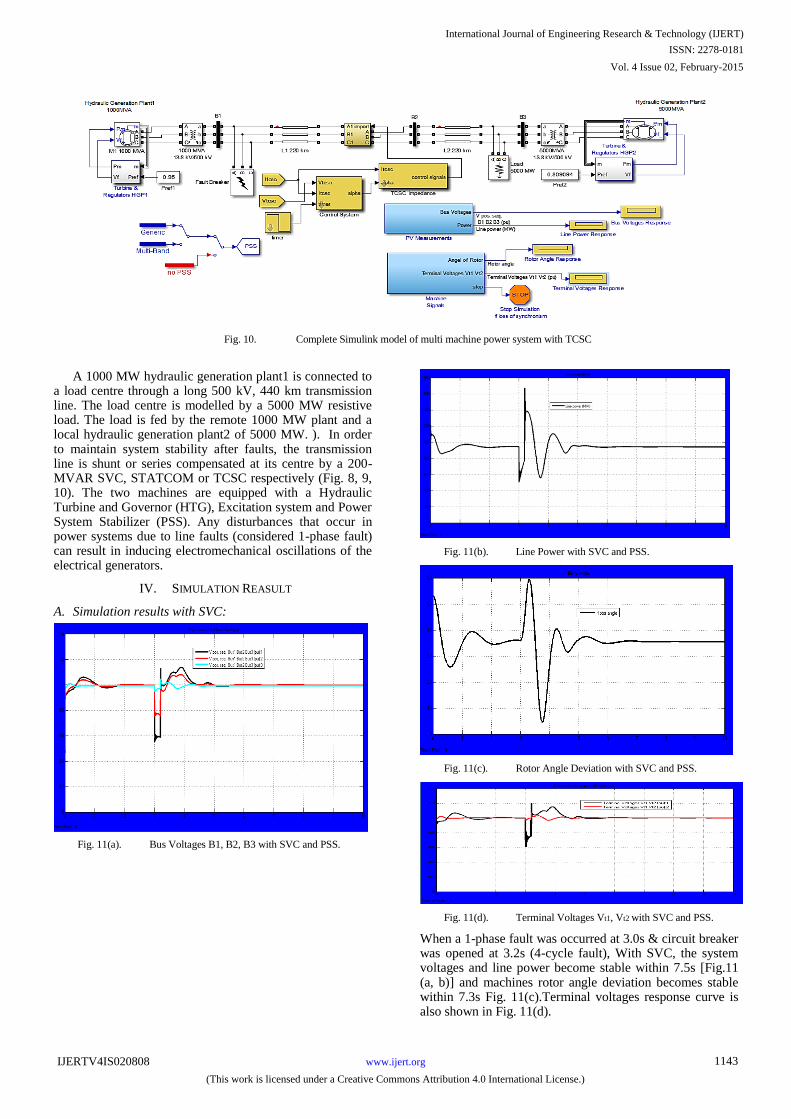
Fig. 10. Complete Simulink model of multi machine power system with TCSC
A 1000 MW hydraulic generation plant1 is connected to a load centre through a long 500 kV, 440 km transmission line. The load centre is modelled by a 5000 MW resistive load. The load is fed by the remote 1000 MW plant and a local hydraulic generation plant2 of 5000 MW. ). In order to maintain system stability after faults, the transmission line is shunt or series compensated at its centre by a 200-MVAR SVC, STATCOM or TCSC respectively (Fig. 8, 9, 10). The two machines are equipped with a Hydraulic Turbine and Governor (HTG), Excitation system and Power System Stabilizer (PSS). Any disturbances that occur in power systems due to line faults (considered 1-phase fault) can result in inducing electromechanical oscillations of the electrical generators.
IV. SIMULATION REASULT
A. Simulation results with SVC:
Fig. 11(a). Bus Voltages B1, B2, B3 with SVC and PSS.
Fig. 11(b). Line Power with SVC and PSS.
Fig. 11(c). Rotor Angle Deviation with SVC and PSS.
Fig. 11(d). Terminal Voltages Vt1, Vt2 with SVC and PSS.
When a 1-phase fault was occurred at 3.0s & circuit breaker was opened at 3.2s (4-cycle fault), With SVC, the system voltages and line power become stable within 7.5s [Fig.11 (a, b)] and machines rotor angle deviation becomes stable within 7.3s Fig. 11(c).Terminal voltages response curve is also shown in Fig. 11(d).
International Journal of Engineering Research & Technology (IJERT)
ISSN: 2278-0181
www.ijert.orgIJERTV4IS020808
(This work is licensed under a Creative Commons Attribution 4.0 International License.)
Vol. 4 Issue 02, February-2015
1143
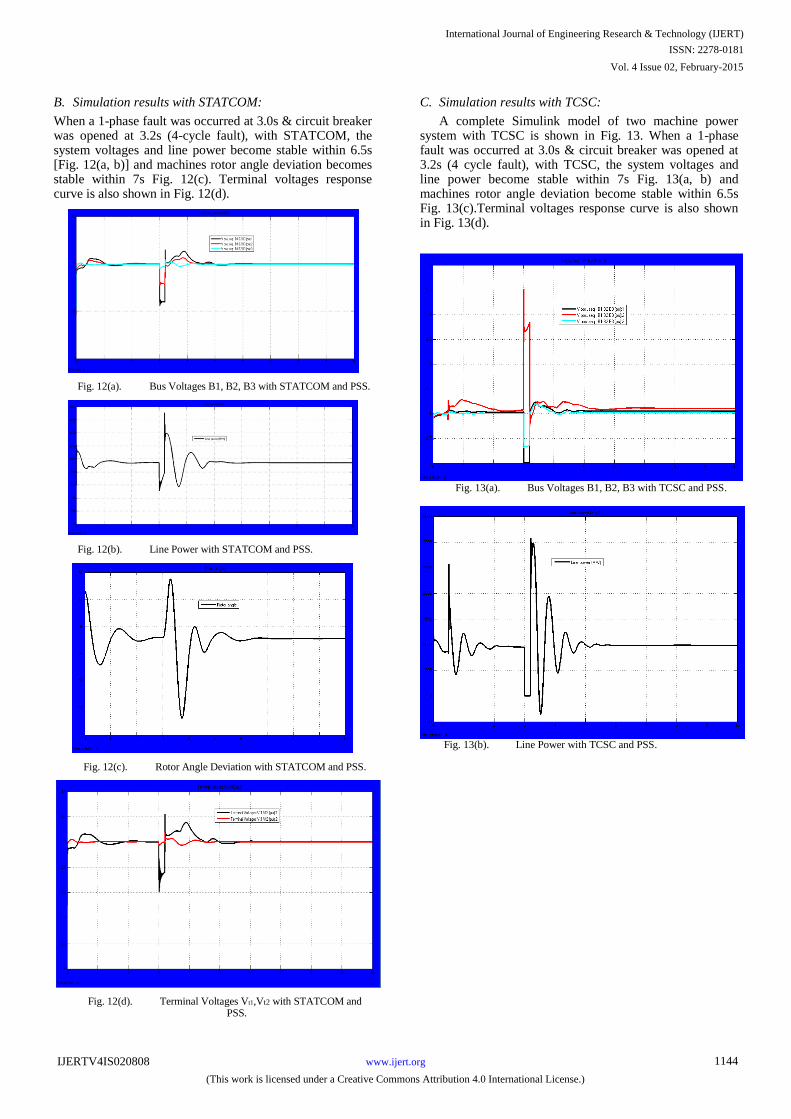
B. Simulation results with STATCOM:
When a 1-phase fault was occurred at 3.0s & circuit breaker was opened at 3.2s (4-cycle fault), with STATCOM, the system voltages and line power become stable within 6.5s [Fig. 12(a, b)] and machines rotor angle deviation becomes stable within 7s Fig. 12(c). Terminal voltages response curve is also shown in Fig. 12(d).
Fig. 12(a). Bus Voltages B1, B2, B3 with STATCOM and PSS.
Fig. 12(b). Line Power with STATCOM and PSS.
Fig. 12(c). Rotor Angle Deviation with STATCOM and PSS.
Fig. 12(d). Terminal Voltages Vt1,Vt2 with STATCOM and PSS.
C. Simulation results with TCSC:
A complete Simulink model of two machine power system with TCSC is shown in Fig. 13. When a 1-phase fault was occurred at 3.0s & circuit breaker was opened at 3.2s (4 cycle fault), with TCSC, the system voltages and line power become stable within 7s Fig. 13(a, b) and machines rotor angle deviation become stable within 6.5s Fig. 13(c).Terminal voltages response curve is also shown in Fig. 13(d).
Fig. 13(a). Bus Voltages B1, B2, B3 with TCSC and PSS.
Fig. 13(b). Line Power with TCSC and PSS.
International Journal of Engineering Research & Technology (IJERT)
ISSN: 2278-0181
www.ijert.orgIJERTV4IS020808
(This work is licensed under a Creative Commons Attribution 4.0 International License.)
Vol. 4 Issue 02, February-2015
1144
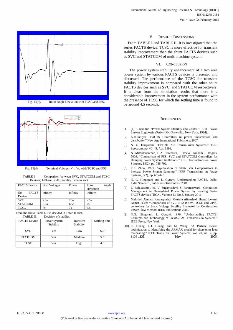
Fig. 13(c). Rotor Angle Deviation with TCSC and PSS.
Fig. 13(d). Terminal Voltages Vt1, Vt2 with TCSC and PSS.
TABLE I. Comparison between SVC, STATCOM and TCSC
Devices; 1-Phase Fault (Stability Time in sec).
FACTS Device Bus Voltages Power Rotor Angle
Deviation
No FACTS Device
infinity infinity infinity
SVC 7.5s 7.5s 7.5s
STATCOM 6.5s 6.5s 7s
TCSC 7s 7s 6.5
From the above Table I. it is decided in Table II. that,
TABLE II. Decision of stability.
FACTS Device Power System Stability
Transient Stability
Settling time
SVC Yes Low 6.5
STATCOM Yes Medium 5.5
TCSC Yes High 4.5
V. RESULTS DISCUSSIONS
From TABLE I and TABLE II, It is investigated that the
series FACTS device, TCSC is more effective for transient
stability improvement than the shunt FACTS devices such
as SVC and STATCOM of multi machine system.
VI. CONCLUSION
The power system stability enhancement of a two area power system by various FACTS devices is presented and discussed. The performance of the TCSC for transient stability improvement is compared with the other shunt FACTS devices such as SVC, and STATCOM respectively. It is clear from the simulation results that there is a considerable improvement in the system performance with the presence of TCSC for which the settling time is found to be around 4.5 seconds.
REFERENCES
[1] [1] P. Kundur, “Power System Stability and Control”, EPRI Power
System EngineeringSeries (Mc Graw-Hill, New York, 1994).
[2] K.R.Padiyar “FACTS Controllers in power transmission and distribution”,New Age International Publishers, 2007.
[3] N. G. Hingorani, “Flexible AC Transmission Systems,” IEEE Spectrum, pp. 40–45, Apr. 1993.
[4] N. Mithulananthan, C.A. Canizares, J. Reeve, Graham J. Rogers, 2003, “Comparison of PSS, SVC and STATCOM Controllers for Damping Power System Oscillations,” IEEE Transactions on Power Systems, 18(2), pp. 786-792.
[5] E.Z. Zhou, 1993, “Application of Static Var Compensators to Increase Power System damping,” IEEE Transactions on Power Systems, 8(2), pp. 655-661.
[6] N. G. Hingorani and L. Gyugyi, Understanding FACTS. Delhi, India:Standard , PublishersDistributors, 2001.
[7] L. Rajalakshmi, M. V. Suganyadevi, S. Parameswari, “Congestion Management in Deregulated Power System by locating Series FACTS devices.”IJCA , Volume 13-No 8, January 2011.
[8] Mehrdad Ahmadi Kamarposhti, Mostafa Alinezhad, Hamid Lesani, Nemat Talebi “Comparison of SVC ,STATCOM, TCSC and UPFC controllers for Static Voltage Stability Evaluated by Continuation Power Flow Method. IEEE Publications 2008.
[9] N.G. Hingorani, L. Gyugyi, 1999, “Understanding FACTS: Concepts and Technology of Flexible AC Transmission Systems,” IEEE Press, New York.
[10] C. Huang, C.J. Huang, and M. Wang, "A Particle swarm optimization to identifying the ARMAX model for short-term load forecasting," IEEE Trans. on Power Systems, vol. 20, no. 2, pp. 1126 1133, May 2001133, May 2005.
International Journal of Engineering Research & Technology (IJERT)
ISSN: 2278-0181
www.ijert.orgIJERTV4IS020808
(This work is licensed under a Creative Commons Attribution 4.0 International License.)
Vol. 4 Issue 02, February-2015
1145