compact iodine-stabilized laser operating at 531 nm … compact iodine-stabilized laser... ·...
TRANSCRIPT
Compact iodine-stabilized laseroperating at 531 nm with stability at the10−12 level and using a coin-sized laser
module
Takumi Kobayashi,1,2,3,∗ Daisuke Akamatsu,1 Kazumoto Hosaka,1,3Hajime Inaba,1,3 Sho Okubo,1,3 Takehiko Tanabe,1 Masami Yasuda,1
Atsushi Onae,1,3 and Feng-Lei Hong1,2,3
1National Metrology Institute of Japan (NMIJ), National Institute of Advanced IndustrialScience and Technology (AIST), 1-1-1 Umezono, Tsukuba, Ibaraki 305-8563, Japan
2Department of Physics, Graduate School of Engineering, Yokohama National University,79-5 Tokiwadai, Hodogaya-ku, Yokohama 240-8501, Japan
3JST, ERATO, MINOSHIMA Intelligent Optical Synthesizer Project, ERATO, 1-1-1 Umezono,Tsukuba, Ibaraki 305-8563, Japan∗[email protected]
Abstract: We demonstrate a compact iodine-stabilized laser oper-ating at 531 nm using a coin-sized light source consisting of a 1062-nmdistributed-feedback diode laser and a frequency-doubling element. Ahyperfine transition of molecular iodine is observed using the light sourcewith saturated absorption spectroscopy. The light source is frequencystabilized to the observed iodine transition and achieves frequency stabilityat the 10−12 level. The absolute frequency of the compact laser stabilizedto the a1 hyperfine component of the R(36)32− 0 transition is determinedas 564074632419(8) kHz with a relative uncertainty of 1.4 × 10⁻¹¹.The iodine-stabilized laser can be used for various applications includinginterferometric measurements.
© 2015 Optical Society of America
OCIS codes: (120.4800) Optical standards and testing; (120.3940) Metrology; (300.6320)Spectroscopy, high-resolution.
References and links1. B. J. Bloom, T. L. Nicholson, J. R. Williams, S. L. Campbell, M. Bishof, X. Zhang, W. Zhang, S. L. Bromley,
and J. Ye, “An optical lattice clock with accuracy and stability at the 10−18 level,” Nature 506, 71–75 (2014).2. I. Ushijima, M. Takamoto, M. Das, T. Ohkubo, and H. Katori, “Cryogenic optical lattice clocks,” Nat. Photonics
6, 185–189 (2015).3. T. L. Nicholson, S. L. Campbell, R. B. Hutson, G. E. Marti, B. J. Bloom, R. L. McNally, W. Zhang, M. D. Barrett,
M. S. Safronova, G. F. Strouse, W. L. Tew, and J. Ye, “Systematic evaluation of an atomic clock at 2× 10⁻¹⁸
total uncertainty,” Nat. Commun. 6, 6896 (2015).4. M. L. Eickhoff and J. L. Hall, “Optical frequency standard at 532 nm,” IEEE Trans. Instrum. Meas. 44, 155–158
(1995).5. J. L. Hall, L.-S. Ma, M. Taubman, B. Tiemann, F.-L. Hong, O. Pfister, and J. Ye, “Stabilization and frequency
measurement of the I2-stabilized Nd:YAG laser,” IEEE Trans. Instrum. Meas. 48, 583–586 (1999).6. F.-L. Hong, J. Ishikawa, Y. Zhang, R. X. Guo, A. Onae, and H. Matsumoto, “Frequency reproducibility of an
iodine-stabilized Nd:YAG laser at 532 nm,” Opt. Commun. 235, 377–385 (2004).7. E. J. Zang, J. P. Cao, Y. Li, C. Y. Li, Y. K. Deng, and C. Q. Gao, “Realization of four-pass I2 absorption cell in
532-nm optical frequency standard,” IEEE Trans. Instrum. Meas. 56, 673–676 (2007).
#242122 Received 2 Jun 2015; revised 26 Jul 2015; accepted 27 Jul 2015; published 30 Jul 2015 (C) 2015 OSA 10 Aug 2015 | Vol. 23, No. 16 | DOI:10.1364/OE.23.020749 | OPTICS EXPRESS 20749
8. J. Ye, L. S. Ma, and J. L. Hall, “Molecular iodine clock,” Phys. Rev. Lett. 87, 270801 (2001).9. M. Takamoto, F.-L. Hong, R. Higashi, and H. Katori, “An optical lattice clock,” Nature 435, 321–324 (2005).
10. F.-L. Hong, M. Takamoto, R. Higashi, Y. Fukuyama, J, Jiang, and H. Katori, “Frequency measurement of a Srlattice clock using an SI-second-referenced optical frequency comb linked by a global positioning system (GPS),”Opt. Express 13, 5253–5262 (2005).
11. A. Cingoz, D. C. Yost, T. K. Allison, A. Ruehl, M. E. Fermann, I. Hartl, and J. Ye, “Direct frequency combspectroscopy in the extreme ultraviolet,” Nature 482, 68–71 (2012).
12. Y. Bitou, K. Sasaki, S. Iwasaki, and F.-L. Hong, “Compact I2-stabilized frequency-doubled Nd:YAG laser forlong gauge block interferometer,” Jpn. J. Appl. Phys. 42, 2867–2871 (2003).
13. M. Musha, T. Kanaya, K. Nakagawa, and K. Ueda, “The short- and long-term frequency stabilization of aninjection-locked Nd:YAG laser in reference to a Fabry-Perot cavity and an iodine saturated absorption line,” Opt.Commun. 183, 165–173 (2000).
14. W. Kokuyama, K. Numata, and J. Camp, “Simple iodine reference at 1064 nm for absolute laser frequencydetermination in space applications,” Appl. Opt. 49, 6264–6267 (2010).
15. B. Argence, H. Halloin, O. Jeannin, P. Prat, O. Turazza, E. de Vismes, G. Auger, and E. Plagnol, “Molecularlaser stabilization at low frequencies for the LISA mission,” Phys. Rev. D 81, 082002 (2010).
16. S. Takemoto, A. Araya, J. Akamatsu, W. Morii, H. Momose, M. Ohashi, I. Kawasaki, T. Higashi, Y. Fukuda, S.Miyoki, T. Uchiyama, D. Tatsumi, H. Hanada, I. Naito, S. Telada, N. Ichikawa, K. Onoue, and Y. Wada, “A 100m laser strainmeter system installed in a 1 km deep tunnel at Kamioka, Gifu, Japan,” J. Geodyn. 38, 477–488(2004).
17. F.-L. Hong, J. Ishikawa, Z. Y. Bi, J. Zhang, K. Seta, A. Onae, J. Yoda, and H. Matsumoto, “Portable I2-stabilizedNd:YAG laser for international comparisons,” IEEE Trans. Instrum. Meas. 50, 486–489 (2001).
18. A. Lurie, P. S. Light, J. Anstie, T. M. Stace, P. C. Abbott, F. Benabid, and A. N. Luiten, “Saturation spectroscopyof iodine in hollow-core optical fiber,” Opt. Express 20, 11906–11917 (2012).
19. S. Kremser, B. Bodermann, H. Knockel, and E. Tiemann, “Frequency stabilization of diode lasers to hyperfinetransitions of the iodine molecule,” Opt. Commun. 110, 708–716 (1994).
20. H. Inaba, Y. Daimon, F.-L. Hong, A. Onae, K. Minoshima, T. R. Schibli, H. Matsumoto, M. Hirano, T. Okuno, M.Onishi, and M. Nakazawa, “Long-term measurement of optical frequencies using a simple, robust and low-noisefiber based frequency comb,” Opt. Express 14, 5223–5231 (2006).
21. Y. Nakajima, H. Inaba, K. Hosaka, K. Minoshima, A. Onae, M. Yasuda, T. Kohno, S. Kawato, T. Kobayashi,T. Katsuyama, and F.-L. Hong, “A multi-branch, fiber-based frequency comb with millihertz-level relativelinewidths using an intra-cavity electro-optic modulator,” Opt. Express 18, 1667–1676 (2010).
22. K. Iwakuni, H. Inaba, Y. Nakajima, T. Kobayashi, K. Hosaka, A. Onae, and F.-L. Hong, “Narrow linewidth combrealized with a mode-locked fiber laser using an intra-cavity waveguide electro-optic modulator for high-speedcontrol,” Opt. Express 20, 13769–13776 (2012).
23. H. Inaba, K. Hosaka, M. Yasuda, Y. Nakajima, K. Iwakuni, D. Akamatsu, S. Okubo, T. Kohno, A. Onae, and F.-L. Hong, “Spectroscopy of 171Yb in an optical lattice based on laser linewidth transfer using a narrow linewidthfrequency comb,” Opt. Express 21, 7891–7896 (2013).
24. L. Robertsson, S. Picard, F.-L. Hong, Y. Millerioux, P. Juncar, and L.-S. Ma, “International comparison of 127I2-stabilized frequency-doubled Nd:YAG lasers between the BIPM, the NRLM and the BNM-INM, October 2000,”Metrologia 38, 567–572 (2001).
25. H. Kato, M. Baba, S. Kasahara, K. Ishikawa, M. Misono, Y. Kimura, J. O’Reilly, H. Kuwano, T. Shimamoto, T.Shinano, C. Fujiwara, M. Ikeuchi, N. Fujita, M. H. Kabir, M. Ushino, R. Takahashi, and Y. Matsunobu, Doppler-f ree High Resolution Spectral Atlas o f Iodine Molecule 15,000 to 19,000 cm−1 (JSPS, 2000).
26. M. Lamrini, R. Bacis, D. Cerny, S. Churassy, P. Crozet, and A. J. Ross, “The electronic transition dipole momentof the B0+u → X0+g transition in iodine,” J. Chem. Phys. 100, 8780–8783 (1994).
27. M. Klug, K. Schulze, U. Hinze, A. Apolonskii, E. Tiemann, and B. Wellegehausen, “Frequency stable I2 Ramanlaser excited by a cw frequency doubled monolithic Nd:YAG laser,” Opt. Commun. 184, 215–223 (2000).
28. S. Gerstenkorn and P. Luc, Atlas Du Spectre D′Absorption de la Molecule D′Iode (Editions de CNRS, 1978).29. J. Camparo, J. Coffer, and J. Townsend, “Laser-pumped atomic clock exploiting pressure-broadened optical
transitions,” J. Opt. Soc. Am. B 22, 521–528 (2005).30. Ch. J. Borde, G. Camy, B. Decomps, J.-P. Descoubes, and J. Vigue, “High precision saturation spectroscopy of
127I2 with argon lasers at 5145 A and 5017 A: I-Main resonances,” J. Physique 42, 1393–1411 (1981).31. F.-L. Hong, J. Ye, L.-S. Ma, S. Picard, Ch. J. Borde, and J. L. Hall, “Rotation dependence of electric quadrupole
hyperfine interaction in the ground state of molecular iodine by high-resolution laser spectroscopy,” J. Opt. Soc.Am. B 18, 379–387 (2001).
32. F.-L. Hong, Y. Zhang, J. Ishikawa, A. Onae, and H. Matsumoto, “Vibration dependence of the tensor spin-spinand scalar spin-spin hyperfine interactions by precision measurement of hyperfine structures of 127I2 near 532nm,” J. Opt. Soc. Am. B 19, 946–953 (2002).
33. F.-L. Hong, H. Inaba, K. Hosaka, M. Yasuda, and A. Onae, “Doppler-free spectroscopy of molecular iodine usinga frequency-stable light source at 578 nm,” Opt. Express 17, 1652–1659 (2009).
34. T. Wilken, G. L. Curto, R. A. Probst, T. Steinmetz, A. Manescau, L. Pasquini, J. I. G. Hernandez, R. Rebolo, T.
#242122 Received 2 Jun 2015; revised 26 Jul 2015; accepted 27 Jul 2015; published 30 Jul 2015 (C) 2015 OSA 10 Aug 2015 | Vol. 23, No. 16 | DOI:10.1364/OE.23.020749 | OPTICS EXPRESS 20750
W. Hansch, T. Udem, and R. Holzwarth, “A spectrograph for exoplanet observations calibrated at the centimetre-per-second level,” Nature 485, 611–614 (2012).
35. V. D. Yushkin, A. N. Sapunov, Yu. F. Stus, E. N. Kalish, I. A. Bunin, and D. A. Nosov, “Measurements with thenew GABL-M field ballistic gravimeter under tundra conditions,” Meas. Tech. 54, 1111–1116 (2012).
1. Introduction
Developments in optical frequency standards have been of great interest in a wide range offields over many years and recently led to accuracies at the 10−18 level [1–3]. Iodine-stabilizedlasers were one of the earliest optical frequency standards and are still important for practi-cal applications due to their simplicity and robustness. Of these lasers, a frequency-doubledNd:YAG laser, which is stabilized to an iodine absorption line at 532 nm, has attracted consid-erable attention owing to its very high frequency stability [4–7]. This is mostly due to the factthat molecular iodine has strong and narrow absorption lines near 532 nm. Applications usingthe Nd:YAG laser include a flywheel oscillator or an absolute frequency marker for an opticalfrequency comb [8–11], interferometric measurements of gauge blocks [12], gravitational wavedetection [13–15], and a laser strainmeter for observing earth tides and earthquakes [16].
A compact iodine-stabilized laser emitting in the 532-nm region is attractive for some ofthe above applications. Some compact Nd:YAG systems have already been developed in pre-vious experiments [12, 14, 15, 17], one of which achieved a size of 30 cm × 45 cm [17]. Amore compact configuration could be constructed by using a small iodine cell and light source.Recently, an iodine-loaded hollow-core photonic crystal fiber has been demonstrated as a po-tential alternative to an iodine cell [18]. Regarding the light source, a diode laser operatingnear 1064 nm can be a compact and low-cost alternative to the Nd:YAG laser. The linewidth ofa diode laser, e.g., a distributed-feedback (DFB) diode laser, usually exceeds several hundredkilohertz, whereas that of a Nd:YAG laser is several kilohertz. Nevertheless, a diode-laser-basedscheme may be suitable for applications that require extremely small systems, e.g., space ap-plications [14, 15], and applications that do not demand very high frequency stabilities.
This paper presents a compact iodine-stabilized laser emitting at 531 nm using second har-monic generation (SHG) of a 1062-nm DFB diode laser. This wavelength is determined by thatof a commercially available diode laser. To our knowledge, this is the first report of an iodine-stabilized diode laser in the wavelength region near 532 nm, while there are many iodine-stabilized diode lasers in the other wavelength regions (e.g., see Ref. [19]). To construct a verysimple laser system, we employ the following methods: (i) we adopt a recently-developed coin-sized module containing both the diode laser and an SHG element; (ii) we use a short iodinecell operated at room temperature; and (iii) we stabilize the laser frequency to a sub-Dopplerresolution iodine line by the third-harmonic technique with the frequency modulation of thediode laser, which enables us to eliminate the need for the electro-optic modulator used in thefrequency modulation sideband or modulation transfer methods [4–7]. All the optical parts ofthe iodine-stabilized laser are arranged on a 20 cm × 30 cm breadboard, but can potentiallyfit into an area of considerably less than 10 cm × 10 cm. The above simplifications could de-grade the frequency stability compared with that of previous Nd:YAG systems [4–7]. Here wedemonstrate that our compact laser can achieve a frequency stability at the 10−12 level and afrequency uncertainty at the 10−11 level, which are sufficient for various applications includinggauge block measurements [12].
2. Experimental setup
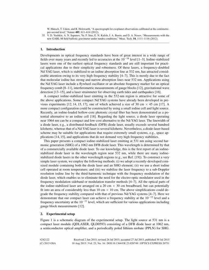
Figure 1 is a schematic diagram of the experimental setup. The light source at 531 nm is acompact laser module (QDLASER, QLD0593) consisting of a DFB diode laser at 1062 nm,a semiconductor optical amplifier, and a periodically poled lithium niobate (PPLN) for SHG.
#242122 Received 2 Jun 2015; revised 26 Jul 2015; accepted 27 Jul 2015; published 30 Jul 2015 (C) 2015 OSA 10 Aug 2015 | Vol. 23, No. 16 | DOI:10.1364/OE.23.020749 | OPTICS EXPRESS 20751
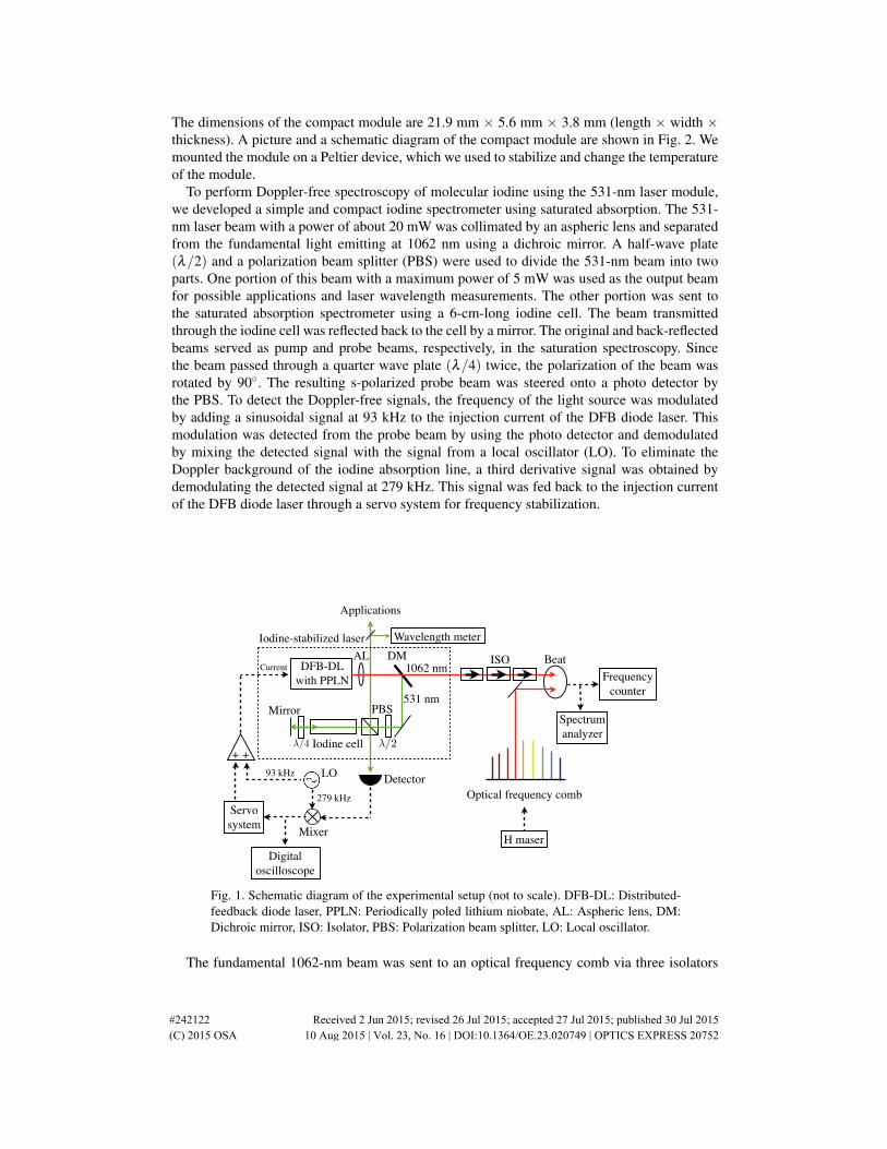
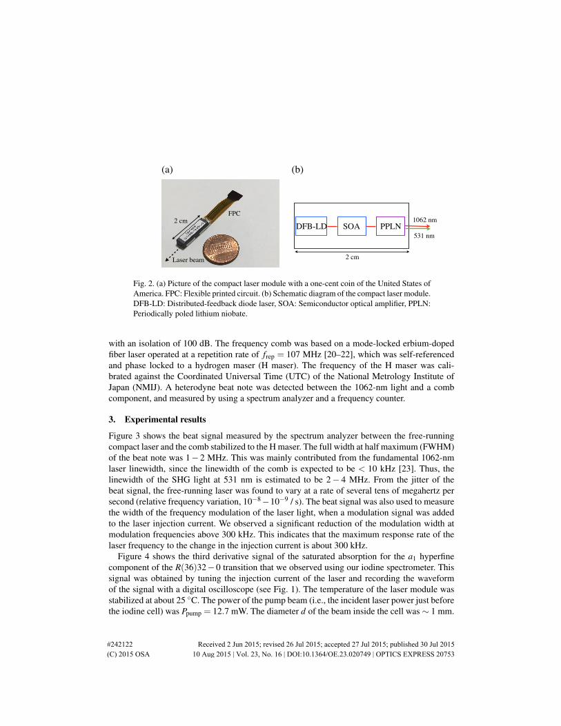
The dimensions of the compact module are 21.9 mm × 5.6 mm × 3.8 mm (length × width ×thickness). A picture and a schematic diagram of the compact module are shown in Fig. 2. Wemounted the module on a Peltier device, which we used to stabilize and change the temperatureof the module.
To perform Doppler-free spectroscopy of molecular iodine using the 531-nm laser module,we developed a simple and compact iodine spectrometer using saturated absorption. The 531-nm laser beam with a power of about 20 mW was collimated by an aspheric lens and separatedfrom the fundamental light emitting at 1062 nm using a dichroic mirror. A half-wave plate(λ/2) and a polarization beam splitter (PBS) were used to divide the 531-nm beam into twoparts. One portion of this beam with a maximum power of 5 mW was used as the output beamfor possible applications and laser wavelength measurements. The other portion was sent tothe saturated absorption spectrometer using a 6-cm-long iodine cell. The beam transmittedthrough the iodine cell was reflected back to the cell by a mirror. The original and back-reflectedbeams served as pump and probe beams, respectively, in the saturation spectroscopy. Sincethe beam passed through a quarter wave plate (λ/4) twice, the polarization of the beam wasrotated by 90. The resulting s-polarized probe beam was steered onto a photo detector bythe PBS. To detect the Doppler-free signals, the frequency of the light source was modulatedby adding a sinusoidal signal at 93 kHz to the injection current of the DFB diode laser. Thismodulation was detected from the probe beam by using the photo detector and demodulatedby mixing the detected signal with the signal from a local oscillator (LO). To eliminate theDoppler background of the iodine absorption line, a third derivative signal was obtained bydemodulating the detected signal at 279 kHz. This signal was fed back to the injection currentof the DFB diode laser through a servo system for frequency stabilization.
DMAL
Mirror PBS
Applications
531 nm
1062 nm
Detector
ISODFB-DLwith PPLN
Beat
H maser
Optical frequency comb Servosystem
Current
+ +
Figure 5.9: Schematic of our setup for the nanosecond titanium-sapphirelaser. ECDL: External cavity diode laser, Ti:S crystal: Titanium-sapphirecrystal, OC: Output coupler, PZT: Piezo transformer, PD: Photodiode, LO:Local oscillator, PID: Proportional-integrating-di!erentiating, BBO: Beta-barium borate crystal.
78
LO
Mixer
93 kHz
279 kHz
/2
Iodine-stabilized laser
Iodine cell/4
Digitaloscilloscope
Wavelength meter
Frequency counter
Spectrum analyzer
Fig. 1. Schematic diagram of the experimental setup (not to scale). DFB-DL: Distributed-feedback diode laser, PPLN: Periodically poled lithium niobate, AL: Aspheric lens, DM:Dichroic mirror, ISO: Isolator, PBS: Polarization beam splitter, LO: Local oscillator.
The fundamental 1062-nm beam was sent to an optical frequency comb via three isolators
#242122 Received 2 Jun 2015; revised 26 Jul 2015; accepted 27 Jul 2015; published 30 Jul 2015 (C) 2015 OSA 10 Aug 2015 | Vol. 23, No. 16 | DOI:10.1364/OE.23.020749 | OPTICS EXPRESS 20752
DFB-LD SOA PPLN1062 nm
531 nm
(a) (b)
2 cm
FPC
Laser beam
2 cm
Fig. 2. (a) Picture of the compact laser module with a one-cent coin of the United States ofAmerica. FPC: Flexible printed circuit. (b) Schematic diagram of the compact laser module.DFB-LD: Distributed-feedback diode laser, SOA: Semiconductor optical amplifier, PPLN:Periodically poled lithium niobate.
with an isolation of 100 dB. The frequency comb was based on a mode-locked erbium-dopedfiber laser operated at a repetition rate of frep = 107 MHz [20–22], which was self-referencedand phase locked to a hydrogen maser (H maser). The frequency of the H maser was cali-brated against the Coordinated Universal Time (UTC) of the National Metrology Institute ofJapan (NMIJ). A heterodyne beat note was detected between the 1062-nm light and a combcomponent, and measured by using a spectrum analyzer and a frequency counter.
3. Experimental results
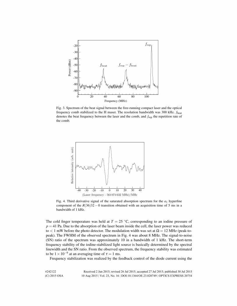
Figure 3 shows the beat signal measured by the spectrum analyzer between the free-runningcompact laser and the comb stabilized to the H maser. The full width at half maximum (FWHM)of the beat note was 1− 2 MHz. This was mainly contributed from the fundamental 1062-nmlaser linewidth, since the linewidth of the comb is expected to be < 10 kHz [23]. Thus, thelinewidth of the SHG light at 531 nm is estimated to be 2− 4 MHz. From the jitter of thebeat signal, the free-running laser was found to vary at a rate of several tens of megahertz persecond (relative frequency variation, 10−8−10−9 / s). The beat signal was also used to measurethe width of the frequency modulation of the laser light, when a modulation signal was addedto the laser injection current. We observed a significant reduction of the modulation width atmodulation frequencies above 300 kHz. This indicates that the maximum response rate of thelaser frequency to the change in the injection current is about 300 kHz.
Figure 4 shows the third derivative signal of the saturated absorption for the a1 hyperfinecomponent of the R(36)32−0 transition that we observed using our iodine spectrometer. Thissignal was obtained by tuning the injection current of the laser and recording the waveformof the signal with a digital oscilloscope (see Fig. 1). The temperature of the laser module wasstabilized at about 25 C. The power of the pump beam (i.e., the incident laser power just beforethe iodine cell) was Ppump = 12.7 mW. The diameter d of the beam inside the cell was∼ 1 mm.
#242122 Received 2 Jun 2015; revised 26 Jul 2015; accepted 27 Jul 2015; published 30 Jul 2015 (C) 2015 OSA 10 Aug 2015 | Vol. 23, No. 16 | DOI:10.1364/OE.23.020749 | OPTICS EXPRESS 20753
0 20 40 60 80 100610×
-90
-80
-70
-60
-50
-40
-30
-20
Frequency (MHz)
Pow
er (d
Bm
)fbeat frep fbeat
frep
Fig. 3. Spectrum of the beat signal between the free-running compact laser and the opticalfrequency comb stabilized to the H maser. The resolution bandwidth was 300 kHz. fbeatdenotes the beat frequency between the laser and the comb, and frep the repetition rate ofthe comb.
Figure 2: Third derivative signal of the a1 component of the R(36)32-0 transition.
0 10 20 30 40-10-20-30-40(Laser frequency - 564 074 632 MHz)/MHz
Rel
ati
ve
inte
nsi
ty(a
rb.
unit
)
Fig. 4. Third derivative signal of the saturated absorption spectrum for the a1 hyperfinecomponent of the R(36)32− 0 transition obtained with an acquisition time of 5 ms in abandwidth of 1 kHz.
The cold finger temperature was held at T = 25 C, corresponding to an iodine pressure ofp = 41 Pa. Due to the absorption of the laser beam inside the cell, the laser power was reducedto < 1 mW before the photo detector. The modulation width was set at Ω = 12 MHz (peak-to-peak). The FWHM of the observed spectrum in Fig. 4 was about 8 MHz. The signal-to-noise(SN) ratio of the spectrum was approximately 10 in a bandwidth of 1 kHz. The short-termfrequency stability of the iodine-stabilized light source is basically determined by the spectrallinewidth and the SN ratio. From the observed spectrum, the frequency stability was estimatedto be 1×10⁻⁹ at an averaging time of τ = 1 ms.
Frequency stabilization was realized by the feedback control of the diode current using the
#242122 Received 2 Jun 2015; revised 26 Jul 2015; accepted 27 Jul 2015; published 30 Jul 2015 (C) 2015 OSA 10 Aug 2015 | Vol. 23, No. 16 | DOI:10.1364/OE.23.020749 | OPTICS EXPRESS 20754
1 10 210 310-1210
-1110
Averaging time (s)
Allan
standard
dev
iati
on
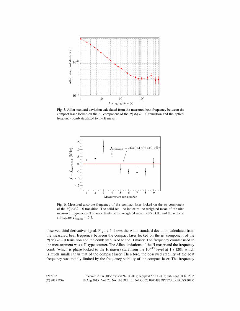
Fig. 5. Allan standard deviation calculated from the measured beat frequency between thecompact laser locked on the a1 component of the R(36)32− 0 transition and the opticalfrequency comb stabilized to the H maser.
Measurement run number1 2 3 4 5 6 7 8 9
Mea
sure
d fre
quen
cy -
Ref
. (kH
z)
-15
-10
-5
0
5
10
1515
10
5
0
-5
-10
-15
f
f avera
ged
(kH
z)
1 2 3 4 5 6 7 8 9Measurement run number
faveraged = 564 074 632 419 kHz
Fig. 6. Measured absolute frequency of the compact laser locked on the a1 componentof the R(36)32− 0 transition. The solid red line indicates the weighted mean of the ninemeasured frequencies. The uncertainty of the weighted mean is 0.91 kHz and the reducedchi-square χ2
reduced = 5.3.
observed third derivative signal. Figure 5 shows the Allan standard deviation calculated fromthe measured beat frequency between the compact laser locked on the a1 component of theR(36)32−0 transition and the comb stabilized to the H maser. The frequency counter used inthe measurement was a Π-type counter. The Allan deviations of the H maser and the frequencycomb (which is phase locked to the H maser) start from the 10−13 level at 1 s [20], whichis much smaller than that of the compact laser. Therefore, the observed stability of the beatfrequency was mainly limited by the frequency stability of the compact laser. The frequency
#242122 Received 2 Jun 2015; revised 26 Jul 2015; accepted 27 Jul 2015; published 30 Jul 2015 (C) 2015 OSA 10 Aug 2015 | Vol. 23, No. 16 | DOI:10.1364/OE.23.020749 | OPTICS EXPRESS 20755
stability of the laser was found to be 5× 10⁻¹¹ at τ = 1 s and reached 3× 10⁻¹² at τ = 700s. For τ > 700 s, the long-term stability was limited by a flicker floor at 3× 10⁻¹². When weassume a 1/τ1/2 slope, the observed stability at τ = 1 s is consistent with the short-term stabilityestimated from the spectral linewidth and SN ratio.
Since the frequency comb is referenced to UTC(NMIJ), i.e., the national frequency standard,the absolute frequency of the iodine-stabilized laser is obtained from the beat measurement.Figure 6 shows the results of nine measurements for the a1 component of the R(36)32− 0transition obtained over several days. In these measurements, the experimental parameters werefixed such that Ppump = 12.7 mW, d ∼ 1 mm, T = 25 C (p = 41 Pa), and Ω = 12 MHz. Eachmeasurement in Fig. 6 was calculated from more than 1000 beat frequency data, where eachfrequency datum was measured by a frequency counter with a gate time of 1 s. The uncertaintybar was given by the Allan standard deviation at the longest averaging time. For example, theuncertainty bar of 1.7 kHz for the measurement run number 6 in Fig. 6 was calculated using theAllan standard deviation of 3× 10⁻¹² at τ = 7000 s in Fig. 5. The weighted mean of the ninemeasured frequencies in Fig. 6 was 564074632419 kHz.
Modulation width (MHz)9 10 11 12 13 14 15 16
Freq
uenc
y sh
ift (k
Hz)
-40
-35
-30
-25
-20
-15
Shift slope = 2.0 kHz/MHzFreq
uenc
y sh
ift (k
Hz)
-15
-20
-25
-30
-35
-409 10 11 12 13 14 15 16
Modulation width (MHz)
(c)
Baseline offset (mV)-3 -2 -1 0 1 2 3 4 5
Mea
sure
d fre
quen
cy -R
ef. (
kHz)
-30
-20
-10
0
10
20
30
40
Iodine pressure (Pa)20 25 30 35 40 45 50 55 60
Freq
uenc
y sh
ift (k
Hz)
-80
-70
-60
-50
-40
-30
Shift slope = 1.3 kHz/Pa
Pump power (mW)5 6 7 8 9 10 11 12 13 14
Freq
uecy
shift
(kH
z)
-50
-45
-40
-35
-30
-25
-20
Shift slope = 3.6 kHz/mW
Iodine pressure (Pa)
Freq
uenc
y sh
ift (k
Hz)
Freq
uenc
y sh
ift (k
Hz)
20 25 30 35 40 45 50 55 60
-30
-40
-50
-60
-70
-80
-20
-25
-30
-35
-40
-45
-50
Pump power (mW)5 6 7 8 9 10 11 12 13 14
(a) (b)
Freq
uenc
y sh
ift (k
Hz)
403020100
-10-20-30
(d)-3 -2 -1 0 1 2 3 4 5
Servo electronics offset (mV)
Shift slope = 7.7 kHz/mV
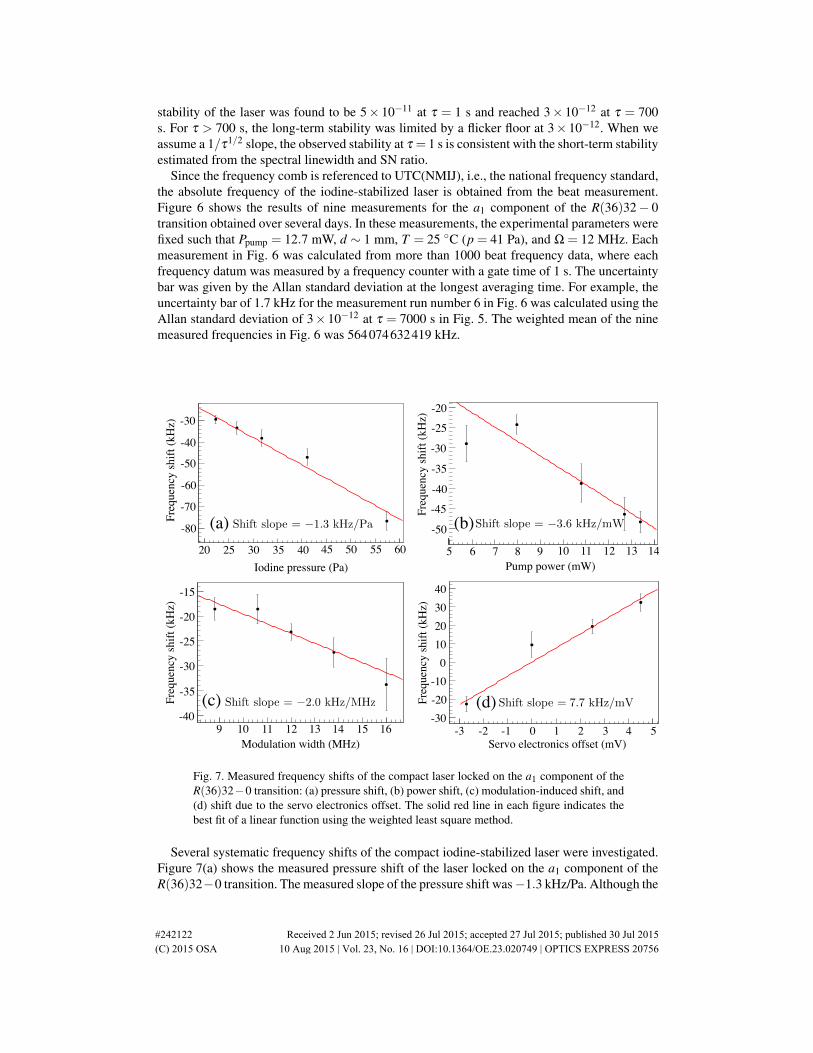
Fig. 7. Measured frequency shifts of the compact laser locked on the a1 component of theR(36)32−0 transition: (a) pressure shift, (b) power shift, (c) modulation-induced shift, and(d) shift due to the servo electronics offset. The solid red line in each figure indicates thebest fit of a linear function using the weighted least square method.
Several systematic frequency shifts of the compact iodine-stabilized laser were investigated.Figure 7(a) shows the measured pressure shift of the laser locked on the a1 component of theR(36)32−0 transition. The measured slope of the pressure shift was−1.3 kHz/Pa. Although the
#242122 Received 2 Jun 2015; revised 26 Jul 2015; accepted 27 Jul 2015; published 30 Jul 2015 (C) 2015 OSA 10 Aug 2015 | Vol. 23, No. 16 | DOI:10.1364/OE.23.020749 | OPTICS EXPRESS 20756
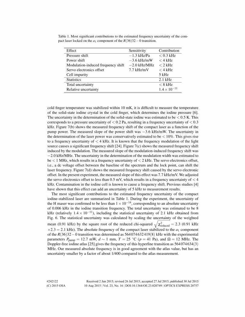
Table 1. Most significant contributions to the estimated frequency uncertainty of the com-pact laser locked on the a1 component of the R(36)32−0 transition.
Effect Sensitivity ContributionPressure shift −1.3 kHz/Pa < 0.3 kHzPower shift −3.6 kHz/mW < 4 kHzModulation-induced frequency shift −2.0 kHz/MHz < 2 kHzServo electronics offset 7.7 kHz/mV < 4 kHzCell impurity 5 kHzStatistics 2.1 kHzTotal uncertainty < 8 kHzRelative uncertainty 1.4×10⁻¹¹
cold finger temperature was stabilized within 10 mK, it is difficult to measure the temperatureof the solid-state iodine crystal in the cold finger, which determines the iodine pressure [6].The uncertainty in the determination of the solid-state iodine was estimated to be < 0.5 K. Thiscorresponds to a pressure uncertainty of < 0.2 Pa, resulting in a frequency uncertainty of < 0.3kHz. Figure 7(b) shows the measured frequency shift of the compact laser as a function of thepump power. The measured slope of the power shift was −3.6 kHz/mW. The uncertainty inthe determination of the laser power was conservatively estimated to be < 10%. This gives riseto a frequency uncertainty of < 4 kHz. It is known that the frequency modulation of the lightsource causes a significant frequency shift [24]. Figure 7(c) shows the measured frequency shiftinduced by the modulation. The measured slope of the modulation-induced frequency shift was−2.0 kHz/MHz. The uncertainty in the determination of the modulation width was estimated tobe < 1 MHz, which results in a frequency uncertainty of < 2 kHz. The servo electronics offset,i.e., a dc voltage offset between the baseline of the spectrum and the lock point, can shift thelaser frequency. Figure 7(d) shows the measured frequency shift caused by the servo electronicoffset. In the present experiment, the measured slope of this effect was 7.7 kHz/mV. We adjustedthe servo electronics offset to less than 0.5 mV, which results in a frequency uncertainty of < 4kHz. Contamination in the iodine cell is known to cause a frequency shift. Previous studies [4]have shown that this effect can add an uncertainty of 5 kHz to measurement results.
The most significant contributions to the estimated frequency uncertainty of the compactiodine-stabilized laser are summarized in Table 1. During the experiment, the uncertainty ofthe H maser was confirmed to be less than 1×10⁻¹⁴, corresponding to an absolute uncertaintyof 0.006 kHz in the iodine transition frequency. The total uncertainty was estimated to be 8kHz (relatively 1.4× 10⁻¹¹), including the statistical uncertainty of 2.1 kHz obtained fromFig. 6. The statistical uncertainty was calculated by scaling the uncertainty of the weighted
mean (0.91 kHz) by the square root of the reduced chi-squared√
χ2reduced = 2.3 (0.91 kHz
×2.3 = 2.1 kHz). The absolute frequency of the compact laser stabilized to the a1 componentof the R(36)32−0 transition was determined as 564074632419(8) kHz with the experimentalparameters Ppump = 12.7 mW, d ∼ 1 mm, T = 25 C (p = 41 Pa), and Ω = 12 MHz. TheDoppler-free iodine atlas [25] gives the frequency of this hyperfine transition as 564074634(3)MHz. Our measured absolute frequency is in good agreement with the atlas value, but has anuncertainty smaller by a factor of about 1/400 compared to the atlas measurement.
#242122 Received 2 Jun 2015; revised 26 Jul 2015; accepted 27 Jul 2015; published 30 Jul 2015 (C) 2015 OSA 10 Aug 2015 | Vol. 23, No. 16 | DOI:10.1364/OE.23.020749 | OPTICS EXPRESS 20757
4. Discussion
The observed spectral linewidth of 8 MHz in Fig. 4 is comparable to the expected value of∆νth = 10− 12 MHz, which was estimated from the pressure width, the power broadening,and the laser linewidth (∆νlaser = 2−4 MHz). The pressure width at p = 41 Pa was tentativelyestimated to be γp = 6 MHz using a pressure broadening coefficient of α = 148 kHz/Pa for theR(56)32−0 transition at 532 nm [4]. Since the spatial distribution of the laser power inside theiodine cell was not uniform due to the strong absorption, we used an average laser power ofPave∼ 6 mW to calculate the Rabi frequency xR. On the assumption that the electronic transitiondipole moment of the observed 531-nm transition is µe = 1 D [26] and the Franck-Condon
factor∣∣∣⟨v
′= 32,J
′= 37
∣∣∣v′′ = 0,J′′= 36
⟩∣∣∣2 (i.e., the square of the overlap integral between theground and excited rovibrational wave functions) is 0.03 [27], xR was estimated to be 3 MHz.The spectral linewidth ∆νth was then calculated from the relationship ∆νth =
√γ2
p +(2xR)2 +
∆νlaser. We note that only order estimation was performed here, since our calculation was basedon our limited knowledge of the parameters such as α , Pave, and µe.
The observed frequency stability of our compact iodine-stabilized laser (shown in Fig. 5) wasworse than that of a previously reported Nd:YAG laser locked on the R(56)32− 0 transition(better than the 10−13 level) [4–7]. This is due to the relatively large spectral linewidth andlow SN ratio observed in the present experiment. Since we used a 6-cm-long iodine cell toconstruct a compact laser system, compared with iodine cells of 30 to 200 cm used in theprevious experiments, we had to increase the iodine pressure and the laser power to obtainan absorption signal with sufficient intensity. This has introduced relatively large pressure andpower broadening effects to the spectral linewidth. Furthermore, the linewidth of the diode laser(2−4 MHz) is much larger than that of the previous Nd:YAG laser (5 kHz). It is worth notinghere that it is reasonable to increase the pressure and power broadening effects to the samelevel as the laser linewidth to realize the best figure of merit (linewidth × SN) for frequencystabilization using the observed spectrum. In terms of the signal, the signal intensity of theR(36)32− 0 transition measured in the present work is expected to be similar to that of theprevious R(56)32− 0 transition [28]. However, a relatively large noise was observed on thebaseline of the spectrum in our experiment. We found that this noise level was significantlyreduced by tuning the laser frequency far from the iodine resonance. The large noise nearresonance is considered to be because the large frequency noise (FM noise) of the diode laseris converted to amplitude noise (AM noise) by the absorptive response of the iodine. This FM-to-AM conversion process has been reported in previous studies using an atomic vapor (e.g.,see Ref. [29]). It should be noted that this conversion effect is small for the narrow linewidthNd:YAG laser.
When the ground state of molecular iodine has an even (odd) rotational quantum number,the rovibrational energy level is split into 15 (21) sublevels, which results in 15 (21) hyperfinecomponents. Frequency measurements of all the hyperfine components of rovibrational linescan contribute to a precise study of the hyperfine structures. A theoretical fit of the measuredhyperfine splittings provides the hyperfine constants [30]. The obtained hyperfine constantsare important for improving or deriving formulas for the hyperfine interactions. For example,previous studies of the iodine hyperfine structures near 532 nm have revealed the rotation andvibration dependence of the hyperfine constants [31, 32]. Here we could in principle study thehyperfine structure of the observed R(36)32− 0 transition. However, some of the hyperfinecomponents near the center of the Doppler absorption were not observed. This is due to thestrong linear absorption at the Doppler center, which degrades the signal level. In the nearfuture, we plan to measure all the hyperfine components of the R(36)32−0 transition at loweriodine pressures using a much longer iodine cell. One alternative to the long iodine cell is an
#242122 Received 2 Jun 2015; revised 26 Jul 2015; accepted 27 Jul 2015; published 30 Jul 2015 (C) 2015 OSA 10 Aug 2015 | Vol. 23, No. 16 | DOI:10.1364/OE.23.020749 | OPTICS EXPRESS 20758
iodine-loaded hollow-core photonic crystal fiber [18]. The combination of the coin-sized lasermodule and the hollow-core photonic crystal fiber could be used to form an ultra compactiodine-stabilized laser. We note that with the new laser, wavelength conversion, and iodinedevices, it is also attractive to investigate iodine transitions at other wavelengths [33].
In most interferometric measurements, the measurement uncertainty is limited at a level of10−9 by the refractive index of air. Therefore, our compact laser can be used for various in-terferometric applications including the measurement of gauge blocks [12]. In the gauge blockmeasurement, an uncertainty arises from the frequency modulation of a light source [12]. There-fore, we need to investigate the effect of the modulation frequency and width employed in thepresent work on the measurement precision of gauge blocks. Such experiments are now underway. More applications of our compact laser include the calibration of a wavelength meter, alaser gravimeter, and as an absolute frequency marker for an astro-comb [34]. For a wavelengthmeter, calibration is periodically needed, since its reading drifts due to variations in environ-mental temperature and pressure. For calibration purposes, a simple and low-cost laser withan accurate absolute frequency is suitable. While iodine-stabilized He-Ne lasers at 633 nm arewidely used in absolute ballistic gravimeters, iodine-stabilized Nd:YAG lasers are also used forthis application (e.g, see Ref. [35]). It is important to construct a compact laser system, sincethe measurement of the gravity is usually carried out in a severe environment. The frequencystability of the laser used in Ref. [35] is at the 10−10 level, and thus our compact laser can beused for this application. An astro-comb has recently been demonstrated for the calibration ofan astronomical telescope [34]. In this scheme, a frequency-stabilized laser is needed to identifythe mode number of the comb. The laser must have a frequency accuracy of better than the rep-etition rate of the comb and be compact and robust enough for installation in an astronomicalobservatory.
Acknowledgments
We are grateful to T. Suzuyama and M. Amemiya for maintaining UTC at NMIJ. We wouldlike to thank Y. Bitou for discussions about the feasibility of the gauge block measurement.
#242122 Received 2 Jun 2015; revised 26 Jul 2015; accepted 27 Jul 2015; published 30 Jul 2015 (C) 2015 OSA 10 Aug 2015 | Vol. 23, No. 16 | DOI:10.1364/OE.23.020749 | OPTICS EXPRESS 20759