commercial duct heaters2 3143335531 brasch manufactures both open coil (figure 1) and finned tubular...
TRANSCRIPT

CommercialDuct Heaters
BR ASCH 425 HANLEY INDUSTRIAL COURT ST. LOUIS, MO 6314 4 USA T 314.333.5531 BR ASCHMFG.COM
CommercialDuct Heaters

1www.braschmfg.com314-333-5531
Choosing Open Coil or Finned Tubular DesignSpecific Requirements3 Calculating KW Requirements3 Static Pressure Drop4 Minimum Velocity4 Maximum Velocity5 Airflow Uniformity6 Multiple Heaters in the Duct6 Clearance7 UL and NEC Requirements7 International Requirements
Installation Information8 Heater Installation8 Field Wiring
Standard Control Options10 Internal Wiring10 Control Option G — Basic10 Control Option J — Pneumatic11 Control Option K — Proportional12 Thermostats
Construction – Electrical14 Bi-Metallic Thermal Cutouts14 Linear Thermal Cutouts15 Airflow Switch15 Fan Relay16 Magnetic Contactors16 Fuses16 Control Transformer17 Disconnect Switch17 Pilot Lights17 Pilot Switch17 Pneumatic/Electric (PE) Switches18 Electronic Controls18 SCR Power Controllers19 Step Controllers (Sequencers)20 Step Controllers (Microprocessor-based)21 Vernier Proportional Control21 Thermostats/Inputs for Electronic Controls
Construction – Mechanical22 Slip-in Heaters22 Flanged Heaters22 Zero Clearance Construction23 Physical Standards
Standard Duct Heaters – Open Coil24 HUA Slip-in and HUP Flanged Heaters24 KW Ratings24 Frame Sizes25 Sizes and Maximum KW Ratings26 Detail Dimensions26 Voltage and Phase26 Control Circuit Options & Special Features26 Number of Heating Stages27 Special Features31 HUA/HUP – Sample Specification
Custom Duct Heaters32 Special Applications33 Round Duct Construction 34 Duct Heaters for Wet, Dusty and Corrosive Areas35 Bottom Mounted Terminal Box35 Insulated Terminal Box35 Pressure Plates36 Protective Screens36 Unheated Sections36 Construction for Lined Ducts37 Slip-and-Drive Construction37 Remote Panelboard37 Minimum & Maximum Duct Dimensions39 Open Coil Custom Heater – Sample Specification40 Finned Tubular Custom Heater – Sample Specification41 Typical Wiring Diagrams
More Brasch Products
Contents

2 www.braschmfg.com314-333-5531
Brasch manufactures both open coil (Figure 1) and finned tubular (Figure 2) heating elements and can supply virtually any duct heater with either type of element. While most simple space heating applications use the open coil design, there are many applications where finned tubular construction is appropriate. The following are the significant advantages of each type of construction.
Open Coil
Only the highest Grade A resistance wire (80% nickel, 20% chromium) is used in all Brasch duct heaters. This iron-free wire has a higher maximum operating temperature, greater life, lower sag, less resistance change and higher corrosion resistance than other commonly used resistance wires.
Using calibrated tooling, the coils are mechanically crimped into stainless steel terminals. This connection, along with 10-32 terminal threads and stainless steel connection hardware, insures cool, minimum resistance, trouble free terminations.
An extended shank on the terminal places the critical resistance coil-to-terminal connection well out into the airstream to keep it cool even in applications where up to 1” of interior insulation is used in the duct.
Both terminal insulators and coil support insulators are fabricated from high-temperature ceramic. Their design and method of installation enable them to: 1) absorb both mechanical and thermal loading without chipping or cracking and 2) easily withstand high voltage dielectric tests.
Element Temperature – The open coil element releases its heat directly into the airstream. As a result, the open coil runs cooler than the coil in the finned tubular element which is isolated from the air by insulation and a metal sheath.
Low Pressure Drop – Because of the high percentage of open space across the heater, open coils have very low pressure drop as compared to finned tubular heaters. This can result in reduced fan motor horsepower and makes it possible to retrofit open coil heaters into existing systems without changing the fan motor.
Large Electrical Clearances – Generous electrical clearances between the coil and frame enable open coils to withstand severe applications such as subway car heating, where voltages may exceed 750 volts.
Economy – On relatively small, low KW heaters (the bulk of typical space heating applications) the open coil element is more economical. However, in large, high KW heaters, finned tubulars are more economical due to lower manufacturing costs.
Smaller Size – It is normally possible to get more KW with open coil construction for a given face area.
Finned Tubular
Finned tubular elements are designed and built by Brasch to meet the requirements of each job. Length, wattage, voltage and element style are engineered to give the most economical package.
All elements consist of a Grade A coil (80% nickel, 20% chromium), precisely centered in a stainless steel tube which is filled with granular magnesium oxide. The entire assembly is compacted to maximize both the heat transfer and dielectric properties of the magnesium oxide. After compaction the tube measures 0.475” (12 mm) O.D., an unusually large diameter providing sufficient insulation for operation up to 600 volts.
A stainless steel fin is helically wound onto the tube to increase its heat transfer surface.
Brasch has standardized on stainless steel for its finned tubular elements because of its superior resistance to moisture and corrosion.
Straight, Two-Pass and U-Bent elements are furnished with mounting flanges, making them individually removable through the terminal box.
Figure 1.
Figure 2.
Choosing Open Coil or Finned Tubular Design
U-Bent
Two-pass
Straight
3www.braschmfg.com314-333-5531
Safety – Because the heating coil is completely encased in a grounded metal sheath, shock hazard due to accidental contact with the coil is eliminated. Heaters installed close to a register, grille, or access door should either use finned tubular construction or an open coil unit with a protective screen.
Airflow Contamination – If airborne contamination, such as dirt or dust, builds up on open coil elements during shutdown periods, the elements can short out. Finned tubular elements, with their insulated coils, eliminate this problem. Furthermore, upon start-up, a finned tubular heater which has been exposed to droplets of water in the airstream (e.g. immediately downstream from a spray type humidifier, a cooling coil, or a fresh air intake) cannot short to ground as open coils can when support bushings are wet.
Serviceability – In the unlikely event of element failure, it is easier to replace individually mounted finned tubular elements than open coil elements.
Mechanical Stability – Finned tubular elements are more rugged than open coils. They will withstand more physical abuse.
Airflow Uniformity – Finned tubular duct heaters tend to be more tolerant of nonuniform airflow conditions. Heat conducted along the element length reduces or eliminates hot spots resulting from nonuniform airflow. With open coil heaters, it may be necessary to use a pressure plate to compensate for bad airflow conditions.
Controllability – Because of their relatively high thermal inertia, finned tubular elements controlled with on/off thermostat systems provide more precise control. Furthermore, finned tubular elements cycle at a reduced rate, thus increasing the life of the power components such as contactors. Nevertheless, when SCR controllers are used, equally precise control can be obtained with either construction.
Calculating KW RequirementsOnce the volume of airflow (CFM – in cubic feet per minute) and the required temperature rise(∆T – in degrees F) through the heater are known, the required kilowatt rating (KW) of the heater can be determined from the formula:
KW = CFM x ∆T°F KW = Liters/Second x ∆T°C3193 837( (
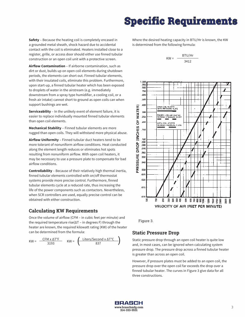
Where the desired heating capacity in BTU/Hr is known, the KW is determined from the following formula:
KW = BTU/Hr
3412
Static Pressure DropStatic pressure drop through an open coil heater is quite low and, in most cases, can be ignored when calculating system pressure drop. The pressure drop across a finned tubular heater is greater than across an open coil.
However, if pressure plates must be added to an open coil, the pressure drop over the open coil far exceeds the drop over a finned tubular heater. The curves in Figure 3 give data for all three constructions.
Figure 3.
Specific Requirements
4 www.braschmfg.com314-333-5531
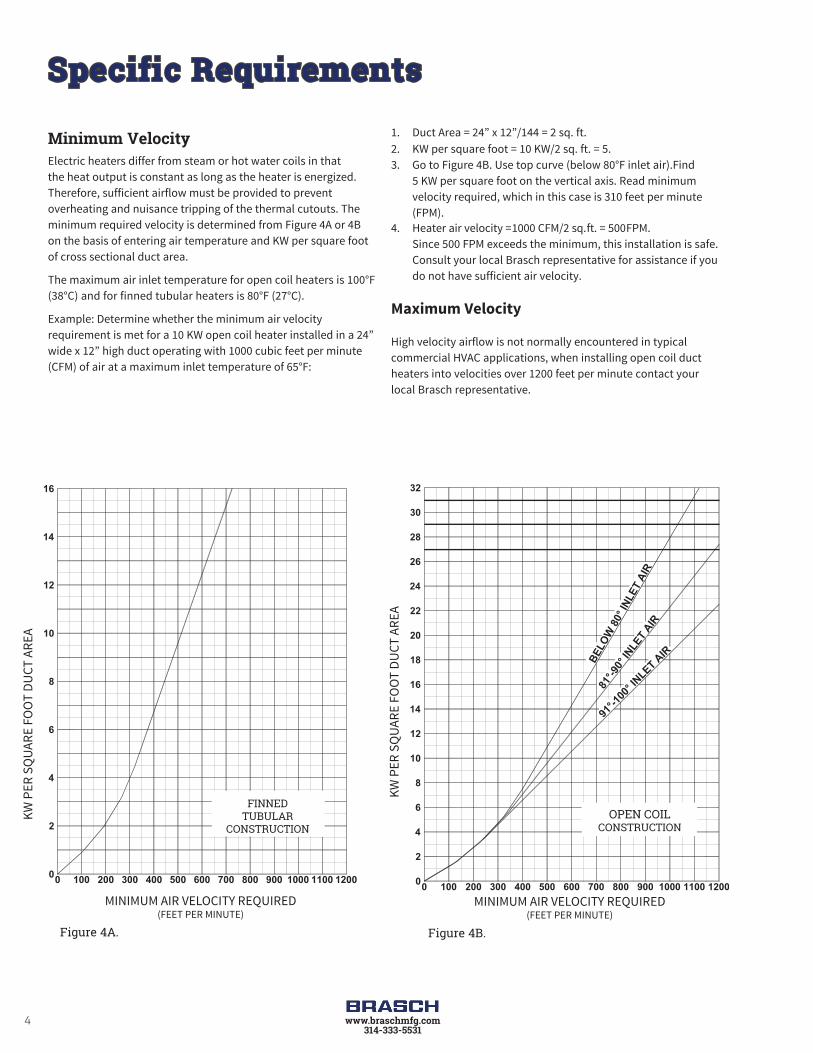
Minimum VelocityElectric heaters differ from steam or hot water coils in that the heat output is constant as long as the heater is energized. Therefore, sufficient airflow must be provided to prevent overheating and nuisance tripping of the thermal cutouts. The minimum required velocity is determined from Figure 4A or 4B on the basis of entering air temperature and KW per square foot of cross sectional duct area.
The maximum air inlet temperature for open coil heaters is 100°F (38°C) and for finned tubular heaters is 80°F (27°C).
Example: Determine whether the minimum air velocity requirement is met for a 10 KW open coil heater installed in a 24” wide x 12” high duct operating with 1000 cubic feet per minute (CFM) of air at a maximum inlet temperature of 65°F:
1. Duct Area = 24” x 12”/144 = 2 sq. ft.2. KW per square foot = 10 KW/2 sq. ft. = 5.3. Go to Figure 4B. Use top curve (below 80°F inlet air).Find
5 KW per square foot on the vertical axis. Read minimum velocity required, which in this case is 310 feet per minute (FPM).
4. Heater air velocity = 1000 CFM/2 sq. ft. = 500 FPM. Since 500 FPM exceeds the minimum, this installation is safe.
Consult your local Brasch representative for assistance if you do not have sufficient air velocity.
Maximum Velocity
High velocity airflow is not normally encountered in typical commercial HVAC applications, when installing open coil duct heaters into velocities over 1200 feet per minute contact your local Brasch representative.
Figure 4A. Figure 4B.
100
2
200 300 400 500 600 700 800 900 1000 1100 1200
4
6
8
10
12
14
16
00
KW P
ER S
QUA
RE F
OO
T DU
CT A
REA
MINIMUM AIR VELOCITY REQUIRED(FEET PER MINUTE)
FINNEDTUBULAR
CONSTRUCTION
MINIMUM AIR VELOCITY REQUIRED(FEET PER MINUTE)
KW P
ER S
QUA
RE F
OO
T DU
CT A
REA
100
2
200 300 400 500 600 700 800 900 1000 1100 1200
4
6
8
10
12
14
16
18
22
24
26
28
30
32
20
91°-1
00° IN
LET AIR
81°-9
0° IN
LET
AIR
BELO
W 8
0° IN
LET
AIR
00
OPEN COILCONSTRUCTION
Specific Requirements

5www.braschmfg.com314-333-5531
Airflow UniformityTo prevent hot spots, airflow must be uniformly distributed across the heater face. Figure 5 illustrates typical heater misapplications which result in non-uniform airflow. The heater’s UL Listing requires that it not be installed closer than 4’ (122 cm) downstream or upstream from a fan outlet, abrupt transition, or other obstructions. Elbows or turns must be located at least 4’ (122 cm) from inlet of the heater and 2’ (61 cm) from outlet of the heater.
If such an installation cannot be avoided, consult your local Brasch representative for assistance. We can provide a pressure plate, non-heated zones or special low watt density coils to overcome these problems. Final approval of such applications is up to the local inspection authority.
Heater too close to fan
Heater too close to elbow
Heater adjacent to transition
Figure 5.
Heater partially blocked by filter or frame member
Specific Requirements

6 www.braschmfg.com314-333-5531
Multiple Heaters in the DuctBrasch heaters are not designed for series installation in a single duct. Since Brasch heaters can be furnished in virtually any size and KW rating, series installation of heaters can be avoided.
For very large heaters, field installation and shipping may be simplified by using two or more sections as illustrated by Figure 6. Each section, furnished in the flanged design, has its own set of thermal limit controls. Terminal blocks are provided to interconnect these cutouts in the field. Sections rest stably one on top of the other.
Heaters more than 6’ (152 cm) high are normally provided in sections, but larger single section heaters can be provided. Consult your local Brasch representative for details.
Clearance
Brasch heaters are UL Listed for zero clearance to combustible surfaces. Thus, there is no minimum distance between combustible materials and the section of duct housing the heater, or the heater itself. However, the terminal box must be accessible for servicing. The NEC requires a minimum workspace at least 30” (76 cm) wide by 42” (107 cm) deep for access to the heater terminal box. More space is required for large heaters and for removal of slip-in heaters which are over 42” long.
In addition, sufficient clearance must be provided for convection cooling of all heaters with built-in SCR power controllers (Figure 7). Allow at least 5” (12.7 cm) of free air space around the cooling fins extending from the heater terminal box. Enclosing the fins in any fashion, insulating them, or preventing them from being cooled by normal convection may cause controller failure and void the heater warranty.
Figure 6.
Figure 7.
Specific Requirements

7www.braschmfg.com314-333-5531
UL and NEC RequirementsAll Brasch electric duct heaters described in this catalog meet the requirements of Underwriters Laboratories (UL) and the National Electrical Code (NEC) unless otherwise indicated.†
Heaters furnished with one of the Control Options on pages 10 and 11 are automatically UL Listed and meet NEC requirements. Custom designed heaters must meet certain requirements to comply with UL and the NEC. The areas of particular concern are outlined below.
Overtemperature Protection – Duct heaters must be supplied with both primary and secondary overtemperature protection. All Brasch heaters are provided with both automatic and manual reset thermal cutouts to serve this function.
Airflow Interlocks – An airflow interlock must be provided to keep the heater from operating with extremely low or no airflow. Brasch’s standard, a built-in differential pressure airflow switch described on page 15, senses static pressure in the duct as an indicator of airflow. Separate wiring to the fan motor or its controls is unnecessary.
Alternative methods for detecting airflow include:
1. The fan relay, described on page 15, provides a positive electrical interlock with the fan circuit.
2. A separate contactor, built into the duct heater, can energize the fan when the duct heater is on.
3. A terminal block to allow field connection of external contacts that close the circuit only when the fan is operating.
Contactors – Contactors connected to the primary thermal cutout and airflow interlock safety circuits must be provided by the duct heater manufacturer. Effective June 2009 UL requires that all open coil element duct heaters be furnished with disconnecting type controlling, safety and backup contactors breaking all ungrounded conductors. Practically speaking, this
means that all, but small 120 and 277 volt single-phase open coil heaters, must be supplied with either disconnecting contactors built into the heater terminal box or into a remote panelboard. Brasch’s standard is to supply disconnecting contactors which break all ungrounded conductors in open coil heaters. Due to the intrinsic safety of finned tubular duct heaters, UL does not require the use of disconnecting type contactors. Brasch’s standard is to supply de-energizing contactors, which break only one line of single-phase circuits and two lines of three-phase circuits. Disconnecting contactors are available with finned tubular heaters if required.
Overcurrent Protection – For heaters drawing more than 48 amps, the duct heater manufacturer must provide some means of overcurrent protection either built into the terminal box or a remote panelboard. While fuses or circuit breakers are available to meet this requirement, Brasch’s standard is fuses.
Disconnecting Means – All duct heater installations require a disconnecting means at or within sight of the heater controls. We recommend that a built-in, snap-acting, door interlocking disconnect switch with marked “on” and “off” positions with lock-out tag-out feature be specified on all duct heaters. This insures the ultimate in safety, since the heater and built-in controls cannot be serviced without turning the disconnect switch off. It is also far less expensive than one obtained and installed in the field.
International RequirementsBrasch heaters can be supplied to operate from any electrical system throughout the world. Single and three-phase voltages through 600 volts are available. As described on pages 24 through 31, all type HUA and HUP standard heaters are available in 380, 400 or 415 volt, three-phase ratings. All Brasch heaters will operate on either 50 or 60 Hz.
Brasch electric duct heaters are available with Canadian Standards Association (CSA) and Canadian Electric Code (CEC) approvals. Consult your Brasch representative for information and availability.
† Although UL requirements are uniform throughout the country, local electrical codes may deviate from the NEC. For information on local requirements, consult your Brasch representative.
Specific Requirements
8 www.braschmfg.com314-333-5531
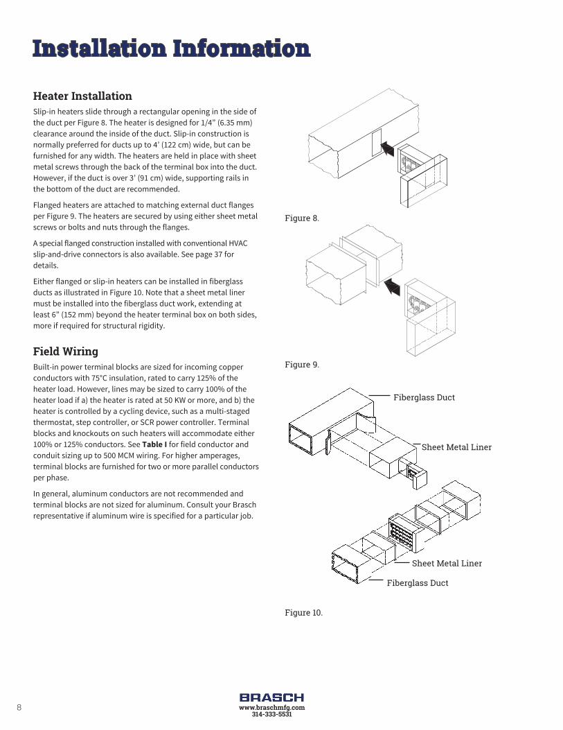
Heater InstallationSlip-in heaters slide through a rectangular opening in the side of the duct per Figure 8. The heater is designed for 1/4” (6.35 mm) clearance around the inside of the duct. Slip-in construction is normally preferred for ducts up to 4’ (122 cm) wide, but can be furnished for any width. The heaters are held in place with sheet metal screws through the back of the terminal box into the duct. However, if the duct is over 3’ (91 cm) wide, supporting rails in the bottom of the duct are recommended.
Flanged heaters are attached to matching external duct flanges per Figure 9. The heaters are secured by using either sheet metal screws or bolts and nuts through the flanges.
A special flanged construction installed with conventional HVAC slip-and-drive connectors is also available. See page 37 for details.
Either flanged or slip-in heaters can be installed in fiberglass ducts as illustrated in Figure 10. Note that a sheet metal liner must be installed into the fiberglass duct work, extending at least 6” (152 mm) beyond the heater terminal box on both sides, more if required for structural rigidity.
Field WiringBuilt-in power terminal blocks are sized for incoming copper conductors with 75°C insulation, rated to carry 125% of the heater load. However, lines may be sized to carry 100% of the heater load if a) the heater is rated at 50 KW or more, and b) the heater is controlled by a cycling device, such as a multi-staged thermostat, step controller, or SCR power controller. Terminal blocks and knockouts on such heaters will accommodate either 100% or 125% conductors. See Table I for field conductor and conduit sizing up to 500 MCM wiring. For higher amperages, terminal blocks are furnished for two or more parallel conductors per phase.
In general, aluminum conductors are not recommended and terminal blocks are not sized for aluminum. Consult your Brasch representative if aluminum wire is specified for a particular job.
Figure 8.
Figure 9.
Figure 10.
Fiberglass Duct
Sheet Metal Liner
Sheet Metal Liner
Fiberglass Duct
Installation Information

9www.braschmfg.com314-333-5531
Field control wiring should also be copper conductors with 75°C insulation. Thermostat circuits for SCR’s and step controllers are NEC Class II. Many small heaters with 24 volt control circuits are also NEC Class II. When Class II wiring is permissible, it will be shown on the wiring schematic. Other control circuits are NEC Class I.
When control power is taken from the heater’s load circuit lines, Brasch provides for the overcurrent protection of all control circuits, as required by NEC or UL. When control circuit power is obtained from a separate source outside the heater, it is necessary for the installer to provide overcurrent protection for all control conductors.
Table I
Field Wiring and Conduit Sizing* for Incoming ConductorsKW in Voltages Shown Wire/
SizeAWG or
MCM
TradeConduit Size
(Inches)LoadAmpsSingle-Phase Three-Phase
120V 208V 240V 277V 208V 240V 480V 1Ø 3Ø
Size
d fo
r 125
% o
f Hea
ter L
oad
1.4 2.4 2.8 3.3 4.3 4.9 9.9 14 1/2 1/2 121.9 3.3 3.8 4.4 5.7 6.6 13.3 12 1/2 1/2 162.8 4.9 5.7 6.6 8.6 9.9 19.9 10 1/2 3/4 244.8 8.3 9.6 11.0 14.4 16.6 33.2 8 3/4 1 406.2 10.8 12.4 14.4 18.7 21.6 43.2 6 1 1 528.1 14.1 16.3 18.8 24.4 28.2 56.5 4 1 1-1/4 689.6 16.6 19.2 22.1 28.8 33.2 66.5 3 1 1-1/4 80
11.0 19.1 22.0 25.4 33.1 38.2 76.4 2 1-1/4 1-1/4 9212.4 21.6 24.9 28.8 37.4 43.2 86.4 1 1-1/4 1-1/2 10414.4 24.9 28.8 33.2 43.2 49.8 99.7 1/0 1-1/4 1-1/2 12016.8 29.1 33.6 38.7 50.4 58.1 116.3 2/0 1-1/2 2 14019.2 33.2 38.4 44.3 57.6 66.5 133.0 3/0 1-1/2 2 16022.0 38.2 44.1 50.9 66.2 76.4 152.9 4/0 2 2-1/2 18424.4 42.4 48.9 56.5 73.4 84.8 169.6 250 2 2-1/2 20427.4 47.4 54.7 63.2 82.1 94.7 189.5 300 2 3 22829.8 51.6 59.5 68.7 89.3 103.0 206.1 350 2-1/2 3 24832.2 55.7 64.3 74.2 96.5 111.4 222.8 400 2-1/2 3 26836.5 63.2 73.0 84.2 109.5 126.3 252.7 500 2-1/2 3 304
Size
d Fo
r 100
% o
f Hea
ter L
oad
54.0 6 1 1 6570.7 4 1 1 8583.1 3 1 1-1/4 10095.6 2 1-1/4 1-1/4 115
54.0 108.1 1 1-1/4 1-1/2 13054.0 62.4 124.7 1/0 1-1/4 1-1/2 15063.0 72.7 145.5 2/0 1-1/2 2 175
55.4 72.1 83.1 166.3 3/0 1-1/2 2 20055.2 63.7 82.9 95.6 191.2 4/0 2 2 230
53.0 61.2 70.6 91.9 106.0 212.0 250 2 2-1/2 25559.2 68.4 78.9 102.6 118.4 236.9 300 2 2-1/2 28564.5 74.4 85.9 111.7 128.9 257.7 350 2-1/2 3 31069.7 80.4 92.8 120.7 139.2 278.5 400 2-1/2 3 335
79.0 91.2 105.3 136.9 158.0 315.9 500 2-1/2 3 380*These tabulations are based on Table 310.15 (B) (16) of the NEC. Not more than 3 conductors in a raceway; 75°C rated copper wire.
Installation Information

10 www.braschmfg.com314-333-5531
Internal WiringCopper wire with a minimum of 105°C insulation is used throughout. Connections are made with either box lugs or connectors crimped on with calibrated tooling. Terminal blocks are provided for all field control and power wiring.
Brasch developed the Control Option concept to maintain compliance with changing UL and NEC requirements and to stay current with new duct heater temperature control systems. The concept has also been broadened to include numerous “Special Features” to meet a wide variety of special requirements.
Control Option G – BasicControl Option G is a basic package designed for normal comfort heating applications – i.e., those that do not require pneumatic control or the unique features of SCR control. With Option G, the temperature is controlled by a pilot duty thermostat or a step controller.
Control Option G includes the following:
• Automatic and manual reset thermal cutouts to protect against overheating. The automatic reset cutout is wired into the control circuit; the manual reset de-energizes the heater load.
• A differential pressure airflow switch to de-energize the heater control circuit upon loss of airflow.
• Magnetic contactors for each heater stage.
• Fuses to protect each circuit in any heater drawing more than 48 amps.
• A control circuit transformer, with 24 or 120 volt secondary as specified, including any overcurrent protection required by UL or the NEC.
• A built-in, snap-acting disconnect switch with door interlock to protect service personnel.
Control Option J – PneumaticControl Option J is designed for pneumatic temperature control.† The contractor need only connect one air line and the main power lines to the heater.
Option J includes the following:
• Automatic and manual reset thermal cutouts and a differential pressure airflow switch. The manual reset thermal cutouts always de-energize the heater load. The automatic reset cutout and airflow switch are normally wired in the control circuit.
• PE switches to control heater staging. To minimize field labor, multiple PE switches are factory-piped to a single port projecting through the terminal box. All PE switches close on pressure rise and open upon loss of pressure to de-energize the heater.
• Magnetic contactors on all Option J heaters.
• Fuses to protect each circuit in any heater drawing more than 48 amps.
• A transformer, with any overcurrent protection required by UL or the NEC, to supply the internal control circuit of heaters rated above 277 volts. All other heaters have line voltage control circuits.
• A built-in, snap-acting disconnect switch with door interlock to protect service personnel.
† Where more than six stages of pneumatic control are required, specify Option G with a step controller and pneumatic transducer as Special Features. Such a heater will function in the same manner as Option J with a maximum of 20 stages.
Standard Control Options

11www.braschmfg.com314-333-5531
Table III
Voltage 120 208 240 277 480 600
MaximumKW
1 Phase 23.0 39.9 46.0 53.1 91.1 115.2
3 Phase — 34.5 39.9 — 79.8 99.7
Table IV
Open Coil Heaters
Single-Phase Voltage 120 208 240 277
Maximum KW 3.0 — — 6.0
Finned Tubular Heaters
Maximum KW 3.0 5.2 6.0 6.0
Control Option K – ProportionalControl Option K is designed for the most precise temperature control, using SCR proportional power controllers and a matching electronic thermostat. For heaters above the KW ratings in Table III, an electronic step controller is also provided. It works with the SCR to provide vernier proportional control. For more details on this system, see page 20.
In addition to these electronic components, Control Option K includes the following:
• Automatic and manual reset thermal cutouts and a differential pressure airflow switch. The manual reset thermal cutouts always de-energize the heater load. The automatic cutout and airflow switch are normally wired in the control circuit. However, when single-phase KW ratings do not exceed the values in Table IV, the automatic reset cutout carries the heater load directly and the airflow switch either carries the load directly or is wired into the control circuit of the SCR, eliminating the need for magnetic contactors.
• Safety magnetic contactors controlled by the automatic reset cutout, for each heater circuit, when the KW exceeds the ratings in Table IV.
• Magnetic contactors for each heater circuit.
• Fuses to protect each circuit in any heater drawing more than 48 amps.
• A transformer, with any overcurrent protection required by UL or the NEC, to supply the internal control circuit of 24 or 120 volts per heater with a step controller for vernier control and 24 volts for all other heaters with SCR control. Wiring to remotely mounted thermostats can be Class II since thermostat circuits are low voltage limited power circuits.
• A built-in, snap-acting disconnect switch with door interlock to protect service personnel.
• A choice of room thermostat, page 12, Figure 15 or 16; duct thermostat, page 13, Figure 20 or 21; built-in PE transducer, page 13, Figure 17; or field inputs of 135 ohms, 2200 ohms, 0-10 VDC and 4-20mA are available.
Wiring DiagramsTypical wiring diagrams for many of the commonly used control options are located on pages 56 – 58. These diagrams of open coil and finned tubular heater constructions are intended to provide general component arrangements and wiring information. Specific wiring diagrams will be attached to the inside of the enclosure doors for each heater and remote panelboard and are available with certified prints.
Standard Control Options

12 www.braschmfg.com314-333-5531
Figure 11.
Figure 12.
Figure 13.
Figure 14.
Figure 15.
Room ThermostatsSingle Stage, Catalog No. 1006998
• Non-digital, non-programmable, snap-acting bimetal, mercury free, SPST, with positive off single stage
• Range: 50° to 90°F (7° to 32°C)
• Accuracy: ±3°F (±1.5°C)
• Color: White
• Inductive Rating: 1.2 amp at 30 volts max
• Offered with duct heater selection
Single Stage, Catalog No. 1023721
• Digital, with programmable 5-1-1 day program or 5-2 day program, mercury free
• HEAT-OFF-COOL-AUTO-EM and fan AUTO-ON selections - CIRC- follow schedule
• Easy to read backlit display
• Range: 40° to 90°F (4.5° to 32°C)
• Accuracy: ±1°F (±0.5°C)
• Color: White
• Inductive Rating: Hardwire, two wire heat only Class II circuit, 1.0 amp at 30 volts max
• Special Order
Two Stage, Catalog No. 1007030
• Digital, non-programmable, mercury free
• COOL-HEAT-OFF EMERGENCY HEAT and fan AUTO-ON selections
• Easy to read backlit display
• Range: 40° to 90°F (4.5° to 32°C)
• Accuracy: ±1°F (±0.5°C)
• Color: White
• Inductive Rating: Hardwire, three wire heat only Class II circuit, 1.0 amp at 30 volts max
Two or Three Stage, Catalog No. 1023723
• Digital, with programmable 5-1-1 day program or 5-2 day program, mercury free
• HEAT-OFF-COOL-AUTO EMERGENCY HEAT and fan AUTO-ON - CIRC- follow schedule selections
• Easy to read backlit display
• Range: 40° to 90°F (4.5° to 32°C)
• Accuracy: ±1°F (±0.5°C)
• Color: White
• Inductive Rating: Hardwire, three or four wire heat only Class II circuit, 1.0 amp at 30 volts max
Electronic Thermostat, Catalog No. 1031404• TA167 Thermostat is proportional 1-10 VDC
• Range: 50° to 90°F
• For use with Brasch controllers
Figure 16.
PE TransducerCatalog No. 1020887• Built into heater terminal box
• PSIG range: 0 to 15
• Throttling range: 1 – 12 psi
• Maximum pressure: 25 psi
• Type: Ohmic – 135 ohms
• For use with Brasch SCR’s and step controllers
Standard Control Options Thermostats

13www.braschmfg.com314-333-5531
Duct ThermostatsSingle Stage Heavy Duty, Catalog No. 1023953
• Liquid filled sensing element with snap-acting contacts
• Range: -30° to 100°F
• Differential: 3 to 12°F between stages
• Bulb Dimensions: ⅜” x 4”
• Capillary Length: 8’
• Resistive Rating: 22 amps, 120 to 277 volts
Electronic Thermostat Catalog No.: Sensor, 1031407
Adjuster, 1031404
• Range: 50° to 90°F
• Type: Proportional 0-10 VDC
• For use with Brasch controller
Electronic Proportional Catalog No.: Sensor, 1001083
Adjuster, 1001068
• Range: 60° to 120°F
• Type: Ohmic – 2200 ohms
• For use with Brasch controllers
Figure 18.
Figure 19.
Figure 17.
Figure 20.
Standard Control Options Thermostats
Two Stage Light Duty, Catalog No. 1007044
• Two single-pole, double throw switches
• Adjustable by screw on graduated cam dial
• Range: 55° to 85°F
• Differential: 2°F between stages
• Bulb Dimensions: 5/8” x 1111/16”
• Capillary Length: 5’6”
• Resistive Rating per Heater Stage: 3.2 amps at 120 volts 1.6 amps at 240 volts

14 www.braschmfg.com314-333-5531
Brasch offers a broad range of electrical components for temperature, safety, and power control.
For most applications, the Control Option system, described in the previous section, makes it easy to specify a complete control package.
For applications requiring a special control system, the following section describes components, their applications, and limitations.
Bi-Metallic Thermal CutoutsBoth UL and NEC require thermal cutout protection against overheating due to insufficient airflow, air blockage or air failure. Two levels of protection are provided:
Figure 22.
The primary or automatic reset thermal cutout (Figure 22) is a fixed temperature, bi-metallic disc type device which opens when its set point is reached and automatically resets when the temperature falls below its set point. The operating disc and contacts are completely enclosed to prevent infiltration of dirt or physical damage. This single pole device is most often wired into the heater control circuit, but will carry single-phase loads up to 25 amps at 240 volts and 22 amps at 277 volts (See Table V). Most heaters have only one automatic reset thermal cutout. However, on large heaters, two or more may be supplied, wired in series.
Table VSingle-Phase Voltage 120 208 240 277
Maximum KW 3.0 5.2 6.0 6.0
The secondary manual reset thermal cutout (Figure 23) has a temperature setting approximately 50°F (28°C) higher than the automatic reset cutout to provide protection only if the primary system fails. Once it has tripped, it is necessary to press a reset tab to return the heater to operation.
Figure 23. Open coil heaters use a cutout rated to carry the maximum heater circuit load allowed by UL and NEC: 48 amps at 480 volts. One cutout is supplied for each heater circuit, or group of circuits, drawing 48 amps or less.
Many manufacturers use heat limiters or fusible links which require field replacement when an overtemperature condition occurs. This often involves removing the heater from the duct and always involves ordering replacement heat limiters from the manufacturer. With Brasch’s manual resets, the heater can immediately be put back into operation, simply by pressing the reset button.
There is no danger that backup protection will be lost because replacement heat limiters are not available. Furthermore, the services of a qualified electrician are not required, since maintenance personnel can easily reset the manual cutouts.
Linear Thermal Cutouts
Figure 24.The linear thermal cutouts (both automatic and manual reset) sensing element (Figure 24) is a fluid-filled capillary tube, strung across the entire heater width. If any 6” (152 mm) segment of the capillary is overheated, the cutout will de-energize the entire heater, providing additional protection if the airflow is
Construction Electrical

15www.braschmfg.com314-333-5531
not sufficiently uniform. Furthermore, it is fail safe – it will trip if the capillary loses its fill. These cutouts are normally provided for pilot duty but can carry a single phase heater load directly up to 20 amps, 277 volts.
Custom open coil heaters – Only one linear automatic and/or one linear manual, set 50°F (10°C) higher than the automatic, may be furnished, in addition to the standard cutouts. They are wired in series with the standard disc type automatic cutout.
Finned tubular heaters – Three levels of over temperature protection are standard for finned tubular heaters. In addition to the automatic disc thermal cutout, Figure 22, both automatic and manual reset linear cutouts, Figure 24, are furnished.
An automatic primary linear limit cutout, strung across the top and leaving air face of the coil (Figure 25), protects against overheating caused by low airflow. This device will turn the heater off if the fixed temperature set point is exceeded. It automatically resets when the temperature drops to safe levels.
Figure 25
Construction Electrical
A manual secondary linear limit cutout protects against failure of the primary overtemperature system. With a fixed temperature setting higher than either of the primary cutouts described above, this device is designed to trip only if both of the primary cutouts stick in the closed position, or controlling contactor points weld together.
Airflow Switch
Figure 26.
A diaphragm operated differential pressure switch (Figure 26) is normally used to prevent a heater from operating unless air is flowing. The switch is provided with a velocity pick-up tube extending into the duct area, making it sensitive to static pressure as well as velocity pressure.
The switch requires at least .07” (17.4 Pa) of water column pressure difference between the inside and the outside of the duct. If the pressure is below .07”, a fan relay should be substituted as described below.
Airflow switches are normally connected for positive pressure – i.e. for a heater located on the discharge side of a fan. If the heater is on the suction side, the switch may be specified or field converted for negative pressure. In most applications the airflow switch is wired into the heater control circuit, but it can carry the heater load directly up to 15 amps at 277 volts, single-phase.
Fan RelayFigure 27
A fan relay is available as an alternate to the standard airflow switch. It has the advantage of being a positive electrical interlock between the fan and the heater (see Figure 27 for wiring details). Its primary disadvantages are that it requires field wiring back to the fan control circuit and does not protect against conditions such as belt failure. When a fan relay is required, specify the fan starter control voltage. If not specified, it will be assumed to be the same as the heater control voltage. Both a fan relay and an airflow switch can be furnished.

16 www.braschmfg.com314-333-5531
Construction Electrical
Magnetic Contactors
Figure 28
All magnetic contactors supplied by Brasch are UL Recognized for limit control duty, as opposed to less severe, general purpose duty. De-energizing contactors, break one power line on single-phase circuits and two lines on three-phase. Disconnecting contactors, break all ungrounded conductors, one power line on 120 and 277 volt single-phase, two power lines on 208 and 240 volt single-phase and all lines on three-phase. Both de-energizing and disconnecting contactors are available with ratings up to 600 volts. Contactors are available with holding coil voltages of 24, 120, 208, 240 or 277.
Fuses
Figure 29
Low resistance fuses are mounted in phenolic fuse blocks fitted with extra tension springs to assure cool connections. To protect against faults in both contactors and heating elements, fuses are located on the line side of contactors built into heaters. To meet NEC requirements for continuous loads, fuses are rated at least 25% above the load they are protecting.
Control Transformer
Figure 30
Built-in control transformers are available to supply either 24 or 120 volt control circuits. The transformer primary is factory connected to the main supply and the secondary is wired directly to the built-in control components. Overcurrent protection and secondary grounding are provided when required by UL and the NEC.
Disconnect Switch
Figure 31.
Built-in disconnect switches are an inexpensive, positive way to meet the NEC requirement for a disconnecting means within sight of the heater, controller(s), and overcurrent protection devices. The switches are interlocked with the heater terminal box cover and have labeled “on” and “off” positions. If there are any external sources of control voltage, a separate toggle switch is provided. Together these devices result in a “dead front” design to protect service personnel. Both fused (up to 48 amps) and unfused switches are available. However, unfused switches are most often specified, as they meet code safety requirements.

17www.braschmfg.com314-333-5531
Construction Electrical
Pilot Lights
Figure 32.
Pilot lights, projecting through the side of the heater terminal box, indicate functional operation. The most commonly specified functions are:
Heater On – This indicates that power has been supplied to the heater, but does not necessarily indicate that the control system is calling for heat or that heat is being produced.
Low Airflow – This indicates that there is either no airflow, or it is so low that the airflow switch has prevented the heater from operating.
Each Stage On – These indicate when each heater stage has been energized. Not available with SCR controlled stages.
Overtemperature – This indicates when the automatic reset thermal cutout has tripped due to an overtemperature condition. Only available with custom heaters.
Pilot SwitchA pilot switch is a simple means of de-energizing the heater between seasons or during prolonged shut-downs. The switch is wired in series with contactor holding coils. It cannot be used as a disconnecting means and is therefore labeled with “on” and “standby” positions. If disconnecting contactors are also specified, the switch will have a labeled “off” position in accordance with UL and NEC provisions.
Pneumatic/Electric (PE) Switches
Figure 33.
Built-in and pre-wired PE switches are available for pneumatic control systems. To minimize field labor, all PE switches are factory piped to a single port projecting through the terminal box. Pneumatic connections may, therefore, be made without interfering with electrical connections. Standard switches close on pressure rise, resulting in a fail-safe system since a loss of pressure de-energizes the heater. “Open on rise” switches are available on custom heaters for special applications.
PE switches can either be used as pilot duty devices, or to carry heater loads up to 22 amps, 480 volts, single-phase.
PE switches are limited to six stages, because it is difficult to calibrate more switches and still maintain proper staging. For more than six stages, specify a step controller (described on pages 19 and 20) with a pneumatic transducer (described on page 13).

18 www.braschmfg.com314-333-5531
Construction Electrical
Electronic ControlsBrasch designs and manufactures the electronic controls supplied with Brasch duct heaters. Controllers manufactured by Brasch have a proven track record of reliability and performance. For custom control application requirements, please contact factory for design options.
Brasch duct heaters may be specified with either SCR power controllers or electronic step controllers. While inherently different, these devices have certain common characteristics:
• Safety – All Brasch electronic control devices are UL Recognized and evaluated for use as a component of Brasch duct heaters.
• Input Flexibility - While normally supplied with a room thermostat, these devices can interface with many field supplied ohmic sensors or electronically generated control signals, such as proportional mA or DC voltages.
• Low Voltage Control – NEC Class II field wiring may be used for the input control signal circuits of all devices.
• High Ambient Temperature Rating – All units are designed for full load operation in high ambient temperatures, making them particularly suitable for use in duct heater and remote panel applications.
• Fail Safe Circuitry – In the event of either a short or open circuit in the input signal leads, all controls de-energize the heaters in order to prevent runaway overheating conditions.
• LED Indicators – LED pilot lights are provided on all controls. For SCR power controllers, the LED is provided to give indication of percentage power output being supplied to the heater. On step controllers, LED indicators are used to convey both operating status and troubleshooting information.
• Continuous Feedback – Logic and control circuits continuously monitor the input signal to provide precise temperature control.
SCR power controllers are provided in many different configurations to support applications in indoor, outdoor and dusty environments. Field selectable inputs are provided to support 4-20 mA, 0-10 VDC, 135 ohm and 2200 ohm signals.
Figure 35. Series 103 for outdoor and dusty applicatons
SCR Power Controllers
Figure 34. 108 Series for indoor use
SCR power controllers modulate the entire heater load between 0-100%. Working on a one second time base, the heater will only be energized for the number of AC cycles necessary to produce the exact required amount of heater resulting in very precise temperature control using the least amount of energy. The resulting precision and rapid response make the Brasch SCR the preferred choice for many heating applications.
The SCR relays are mounted to a finned heat sink which extends outside the heater terminal box or control panel. The heat sink has been specifically designed for maximum heat dissipation. The combination of a conservative SCR rating (no more than 75% of the relay manufacturer’s rating) and an efficiently designed heat sink ensure a long component life by protecting against overheating and SCR failure.
Both single and three phase SCR controllers are available in a master or slave configuration. Each master is capable of driving up to three slaves, giving maximum capability for 100%, fully proportional SCR control. However, when the load exceeds that tabulated in Table III on page 11, it is more economical to utilize

19www.braschmfg.com314-333-5531
Construction Electrical
an Brasch step controller with a slave SCR wired in a vernier control configuration. See page 20 for details.
The SCR is switched on only as the voltage wave form crosses the zero point, which virtually eliminates radio frequency interference (RFI). All 480 and 600 volt SCR’s have a 1200 peak inverse voltage (PIV) rating and transient absorbers that provide protection from high voltage spikes that can be present in 480 and 600 volt lines.
Except on single-phase heaters where the total load can be carried directly by the automatically resettable thermal limit control (see Table V, page 14), all heaters with SCR’s require the limit control to be wired in series with the coil of one or more safety contactors.
The S10 Series step controller is a UL recognized low voltage 24 VAC microcomputer-based stage controller designed to provide low cost precision control for multi-stage applications. Some noted features are:
• Capable of controlling 24, 120 or 240 VAC loads
• 10 stage controller with a pulsed 12 VDC vernier stage rated at 100 mA.
• Up to 20 stages of control when using two units wired in a master & slave configuration
• 24 VDC power supply rated at 200 mA is available for an external sensor.
• Field selectable standard temperature control inputs to support input devices for 4-20 mA, 0-10 VDC, 0-20 VDC, 2200 ohm, 135 ohm and a 3-wire remote thermostat with 0-10 VDC output.
• Supports field selectable custom VDC input ranges with low and high setpoints anywhere between 0-19 VDC .
• Stage delay settings for both ‘ON’ and ‘OFF’ operation can be individually set in the field at any value between 1 second and 10 minutes.
• Functional test mode operation and LED indictators provided for use in troubleshooting.
Figure 36. S10 Electronic Sequencers
Step Controllers
Upon momentary power interruption, the controller will de-energize in order to avoid heavy line surges and to provide a soft start when power is restored.
20 www.braschmfg.com314-333-5531
Construction Electrical
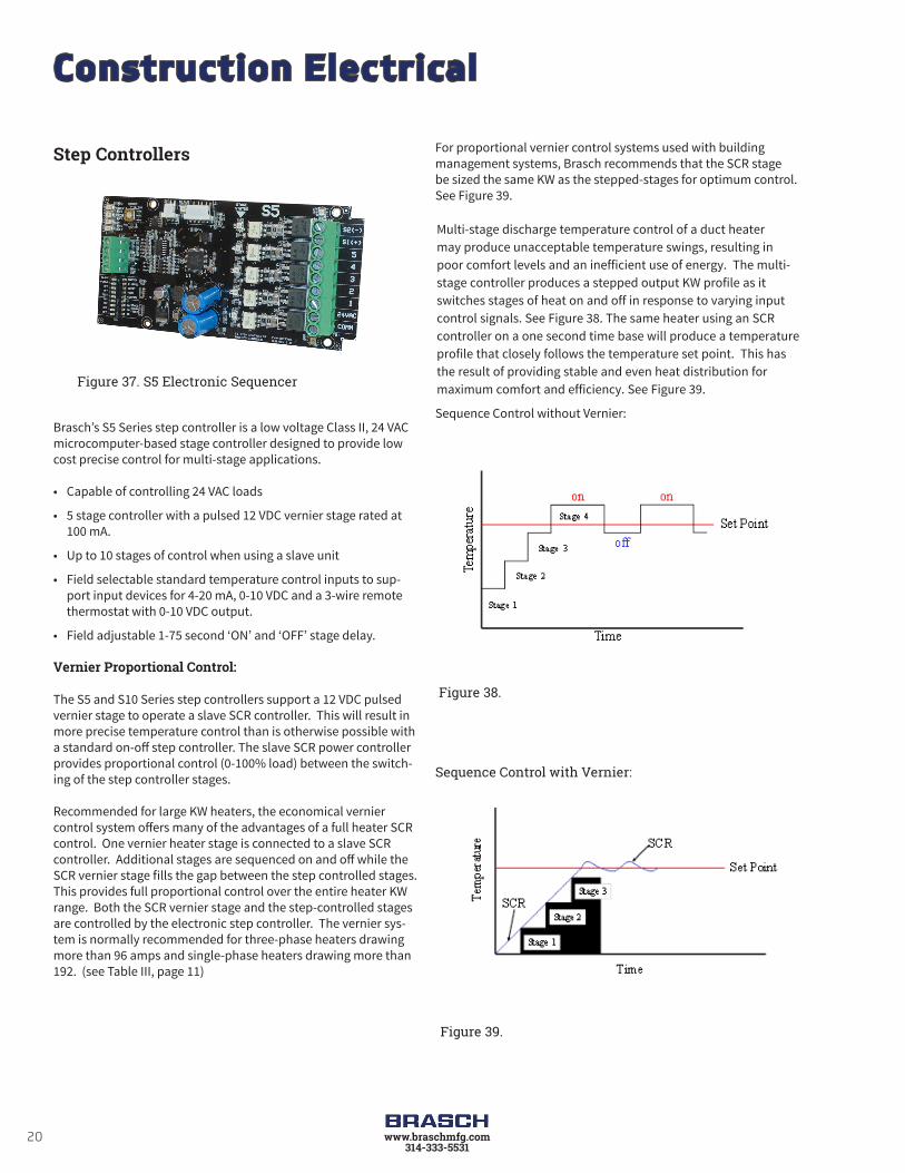
Figure 37. S5 Electronic Sequencer
Step Controllers
Brasch’s S5 Series step controller is a low voltage Class II, 24 VAC microcomputer-based stage controller designed to provide low cost precise control for multi-stage applications.
• Capable of controlling 24 VAC loads
• 5 stage controller with a pulsed 12 VDC vernier stage rated at 100 mA.
• Up to 10 stages of control when using a slave unit
• Field selectable standard temperature control inputs to sup-port input devices for 4-20 mA, 0-10 VDC and a 3-wire remote thermostat with 0-10 VDC output.
• Field adjustable 1-75 second ‘ON’ and ‘OFF’ stage delay.
Vernier Proportional Control:
The S5 and S10 Series step controllers support a 12 VDC pulsed vernier stage to operate a slave SCR controller. This will result in more precise temperature control than is otherwise possible with a standard on-off step controller. The slave SCR power controller provides proportional control (0-100% load) between the switch-ing of the step controller stages.
Recommended for large KW heaters, the economical vernier control system offers many of the advantages of a full heater SCR control. One vernier heater stage is connected to a slave SCR controller. Additional stages are sequenced on and off while the SCR vernier stage fills the gap between the step controlled stages. This provides full proportional control over the entire heater KW range. Both the SCR vernier stage and the step-controlled stages are controlled by the electronic step controller. The vernier sys-tem is normally recommended for three-phase heaters drawing more than 96 amps and single-phase heaters drawing more than 192. (see Table III, page 11)
For proportional vernier control systems used with building management systems, Brasch recommends that the SCR stage be sized the same KW as the stepped-stages for optimum control. See Figure 39.
Multi-stage discharge temperature control of a duct heater may produce unacceptable temperature swings, resulting in poor comfort levels and an inefficient use of energy. The multi-stage controller produces a stepped output KW profile as it switches stages of heat on and off in response to varying input control signals. See Figure 38. The same heater using an SCR controller on a one second time base will produce a temperature profile that closely follows the temperature set point. This has the result of providing stable and even heat distribution for maximum comfort and efficiency. See Figure 39.
Sequence Control without Vernier:
Sequence Control with Vernier:
Figure 38.
Figure 39.

21www.braschmfg.com314-333-5531
Construction Electrical
Thermostats and Sensors for Electronic ControlsAn electronic proportional room thermostat (page 12, Figure 16) is standard for all Brasch SCR and electronic step controllers. A duct type sensor is also available (page 13, Figure 21).
When a field-supplied sensor is used, the sensor can be specified with any of the inputs listed in Table VI:
Table VI
Available Input Signal Types for Brasch Controllers:
Inputs1
Spans (Factory Set)
SCR’s S5 StepController
S10 StepController
2200 ohms 100 ohms N/A
40-400 ohm
(Adjust-able)
135 ohms 100 ohms N/A 120 ohms
4-20 mA2 12.8 mA 15 mA 15 mA
0-10 VDC 8.0 VDC 9 VDC 9 VDC
1. All inputs listed in the table above are available with HUA and HUP type heaters. These inputs plus a variety of other inputs are available with custom heaters.
2. Standard input impedance is 10KΩ for VDC inputs and 250Ω for mA inputs
Custom Control Capabilities
While standard Brasch SCR’s and step contollers satisfy the majority of HVAC applications, a much broader range of special capabilities are also available with Brasch custom heaters. Some typical examples are:
• Fan Motor Hookup and Protection – In addition to control of the heater, it is often desirable to branch the fan motor power from the heater supply circuit. The heater is designed so that the electrician brings only one power circuit into the heater wiring enclosure which is then internally subdivided for fan power. The motor starter, overloads and overcurrent protec-tion for the auxiliary fan motor circuit will be provided.
• Low Limit Discharge Control – A thermostat is placed in the occupied area which has primary control of the heater. A second thermostat is wired in parallel and placed in the dis-charge duct. This second thermostat will override the room thermostat and is set to keep the discharge air temperature above a predetermined temperature. This prevents cold air from being discharged into the occupied area.
• Temperature Averaging – Multiple sensors, with a single set point, are placed in different zones or in several locations of a large area, such as a warehouse. The controller averages the readings of all the sensors to determine the heater output. This design can be used in the hot deck of multizone units.

22 www.braschmfg.com314-333-5531
Construction Mechanical
Slip-in heaters are designed so that the entire frame, except the terminal box, slips into the duct with 1/4” (6.35mm) clearance all around. It is installed, as shown in Figure 8 on page 8, through a rectangular opening in the side of the duct and held in place with sheet metal screws through the back of the terminal box, which is large enough to provide a seal with the duct. Figure 40 illustrates the construction and provides reference dimensions.
Slip-in construction is used because it allows duct work to be installed before the heaters are available, simplifies on-the-job changes in heater location, and is easily retrofitted into existing duct systems. Furthermore, small slip-in heaters may be installed without any special provisions for their support.
While custom slip-in heaters can be provided to fit specific duct dimensions (W x H), selecting standard open coil type HUA heaters maximizes economy and minimizes delivery times.
Flanged construction is available with inside face dimensions exactly matching the duct dimensions. The heater frame is attached to matching turned out duct flanges as illustrated in Figure 9 on page 8. Standard flanges are a minimum of
3/4” deep; deeper flanges are provided on larger heaters for structural reasons. Custom flanges can be provided upon request. Figure 41 illustrates flanged heater construction and provides reference dimensions.
Standard HUP flanged heaters are available to meet many of the commonly used duct sizes. Listings of the available sizes are shown on page 25. Full range of control options and construction features are offered.
Zero Clearance ConstructionSlip-in and flanged heaters are UL Listed for zero clearance, allowing combustible material to be placed directly against surrounding duct work. Although this construction is not required by UL on heaters above 50 KW, Brasch supplies it on all heaters regardless of KW. However, incorrect mounting will void the UL Listing, and may make the installation unsafe.
Figure 41.
Flanged Heaters
Figure 40.
Slip-In Heaters

23www.braschmfg.com314-333-5531
Construction Mechanical
Standardized dimensions and terminology avoid errors and confusion. The most common dimensions are defined in Figures 40 and 41.
Figures 42 and 43 illustrate airflow terminology. Most Brasch open coil type heaters are suitable for horizontal or vertical airflow, but for finned tubular type heaters or heaters with pressure plates, exact airflow direction (right, left, up or down) must be specified.
In most heaters, the terminal box is significantly larger than the heater frame, in at least one direction. This is referred to as the terminal box overhang, defined in Figures 42 and 43. For horizontal airflow, left overhang is standard. For vertical airflow, up overhang is standard. Optional right and down overhangs are also available.
Heater Frame and Terminal Box
Frames and terminal boxes are fabricated from heavy gauge corrosion resistant steel. Optional stainless steel frames are recommended for wet or corrosive applications. Standard NEMA 1 type terminal boxes have hinged covers.
Knockouts are provided for all field connections. Open coil heater element support brackets are spaced on 4.5” (114 mm) maximum centers to avoid coil sag, even under the most extreme operating conditions. Strengthening ribs on the brackets insure that coils are held in their proper location, even on large heaters.
Finned tubular heater element support brackets are spaced on 36” (914 mm) maximum centers.
Figure 43.
Figure 42.
Physical Standards

24 www.braschmfg.com314-333-5531
Standard Duct Heater Open Coil
HUA Slip-In and HUP Flanged Heaters
Figure 44.
Brasch has developed HUA (Figure 44) and HUP (Figure 46) heater lines to satisfy most typical space heating requirements, simplifying specification, ordering and delivery.
Both standard and quick ship delivery programs are available for the full line of HUA and HUP heaters.
KW Ratings HUA and HUP heaters are available up to 456 KW. The KW ratings are limited both by frame size and electrical characteristics. Heater availability can be determined by contacting an Brasch representative, who can provide a computerized heater selection with exact heater dimensions in minutes.
Frame Sizes The use of a standard open coil HUA slip-in heater will both reduce cost and permit rapid shipment. HUA frame sizes range from the smallest at 8” wide by 6” high to the largest 48” wide by 40” high or 72” wide by 30” high. The HUA offering has been opened up to allow for any duct size in between these sizes and includes fractional widths and heights dimensions (i.e. 24.625” by 17.25”). Brasch can manufacture a custom slip-in frame size if your requirements exceed the HUA offering.
The 80% Rule – Brasch recommends the heater should occupy at least 80% of the actual inside area of the duct, as shown in Figure 45. Only small amounts of air will bypass the heater around its perimeter and normal turbulence will rapidly mix this unheated air with heated air downstream.
Figure 46.
Figure 45.
All HUA heaters may be installed in ducts with up to 1” of interior lining, but the heater must be selected to fit the inside duct dimensions. For example, to fit a duct with 36” x 16” outside dimensions, but with 1” of interior insulation, specify a 35” x 14” heater.
HUP flanged open coil heater frame sizes range from the smallest at 8” wide by 6” high to the largest at 48” wide by 38” high or 72” wide by 28” high or any duct size in between these sizes (i.e. 35.75” by 27.75”).
25www.braschmfg.com314-333-5531
Standard Duct Heater Open Coil
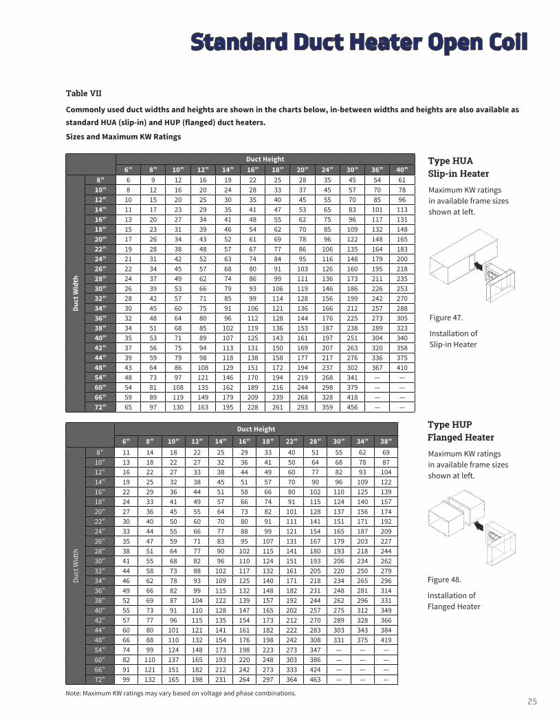
Table VII
Commonly used duct widths and heights are shown in the charts below, in-between widths and heights are also available as standard HUA (slip-in) and HUP (flanged) duct heaters.
Sizes and Maximum KW Ratings
Duct Height6” 8” 10” 12” 14” 16” 18” 20” 24” 30” 36” 40”
Duct
Wid
th
8” 6 9 12 16 19 22 25 28 35 45 54 6110” 8 12 16 20 24 28 33 37 45 57 70 7812” 10 15 20 25 30 35 40 45 55 70 85 9614” 11 17 23 29 35 41 47 53 65 83 101 11316” 13 20 27 34 41 48 55 62 75 96 117 13118” 15 23 31 39 46 54 62 70 85 109 132 14820” 17 26 34 43 52 61 69 78 96 122 148 16522” 19 28 38 48 57 67 77 86 106 135 164 18324” 21 31 42 52 63 74 84 95 116 148 179 20026” 22 34 45 57 68 80 91 103 126 160 195 21828” 24 37 49 62 74 86 99 111 136 173 211 23530” 26 39 53 66 79 93 106 119 146 186 226 25332” 28 42 57 71 85 99 114 128 156 199 242 27034” 30 45 60 75 91 106 121 136 166 212 257 28836” 32 48 64 80 96 112 128 144 176 225 273 30538” 34 51 68 85 102 119 136 153 187 238 289 32340” 35 53 71 89 107 125 143 161 197 251 304 34042” 37 56 75 94 113 131 150 169 207 263 320 35844” 39 59 79 98 118 138 158 177 217 276 336 37548” 43 64 86 108 129 151 172 194 237 302 367 41054” 48 73 97 121 146 170 194 219 268 341 — —60” 54 81 108 135 162 189 216 244 298 379 — —66” 59 89 119 149 179 209 239 268 328 418 — —72” 65 97 130 163 195 228 261 293 359 456 — —
Figure 47.
Installation of Slip-in Heater
Figure 48.
Installation of Flanged Heater
Type HUA Slip-in Heater
Maximum KW ratings in available frame sizes shown at left.
Type HUP Flanged Heater
Maximum KW ratings in available frame sizes shown at left.
Duct Height
6” 8” 10” 12” 14” 16” 18” 22” 28” 30” 34” 38”
Duct
Wid
th
8” 11 14 18 22 25 29 33 40 51 55 62 6910” 13 18 22 27 32 36 41 50 64 68 78 8712” 16 22 27 33 38 44 49 60 77 82 93 10414” 19 25 32 38 45 51 57 70 90 96 109 12216” 22 29 36 44 51 58 66 80 102 110 125 13918” 24 33 41 49 57 66 74 91 115 124 140 15720” 27 36 45 55 64 73 82 101 128 137 156 17422” 30 40 50 60 70 80 91 111 141 151 171 19224” 33 44 55 66 77 88 99 121 154 165 187 20926” 35 47 59 71 83 95 107 131 167 179 203 22728” 38 51 64 77 90 102 115 141 180 193 218 24430” 41 55 68 82 96 110 124 151 193 206 234 26232” 44 58 73 88 102 117 132 161 205 220 250 27934” 46 62 78 93 109 125 140 171 218 234 265 29636” 49 66 82 99 115 132 148 182 231 248 281 31438” 52 69 87 104 122 139 157 192 244 262 296 33140” 55 73 91 110 128 147 165 202 257 275 312 34942” 57 77 96 115 135 154 173 212 270 289 328 36644” 60 80 101 121 141 161 182 222 283 303 343 38448” 66 88 110 132 154 176 198 242 308 331 375 41954” 74 99 124 148 173 198 223 273 347 — — —60” 82 110 137 165 193 220 248 303 386 — — —66” 91 121 151 182 212 242 273 333 424 — — —72” 99 132 165 198 231 264 297 364 463 — — —
Note: Maximum KW ratings may vary based on voltage and phase combinations.
26 www.braschmfg.com314-333-5531
Detail DimensionsThe wide variety of HUA and HUP (Figures 47 and 48) heaters makes it impractical to list the exact heater dimensions for every possible heater. For dimensional details, contact your local Brasch representative.
Voltage and PhaseHeaters are available in the voltage and phase combinations shown below. All are for operation at 50 or 60 Hz.
When three-phase is specified, each heating stage will be furnished with a multiple of three elements to give a balanced three-phase load.
Voltage 120 208 240 277 208 240 380 400 415 480 600
Phase 1 3
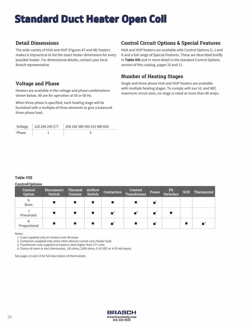
Table VIII
Control OptionsControlOption
DisconnectSwitch
ThermalCutouts
AirflowSwitch Contactors Control
Transformer Fuses PESwitches SCR Thermostat
GBasic
1
JPneumatic
2
3
1
KProportional
2 1
4
Notes: 1. Fuses supplied only on heaters over 48 amps. 2. Contactors supplied only when other devices cannot carry heater load. 3. Transformer only supplied on heaters rated higher than 277 volts. 4. Choice of room or duct thermostat, 135 ohms, 2200 ohms, 0-10 VDC or 4-20 mA inputs.
See pages 12 and 13 for full description of thermostats.
Control Circuit Options & Special FeaturesHUA and HUP heaters are available with Control Options G, J and K and a full range of Special Features. These are described briefly in Table VIII and in more detail in the standard Control Options section of this catalog, pages 10 and 11.
Number of Heating Stages Single and three-phase HUA and HUP heaters are available with multiple heating stages. To comply with our UL and NEC maximum circuit sizes, no stage is rated at more than 48 amps.
Standard Duct Heater Open Coil

27www.braschmfg.com314-333-5531
Special FeaturesWhile HUA slip-in and HUP flanged heaters may be specified with one of the standard control circuit options, individual job requirements may demand slight variations from the standards. The most common variations are covered by Brasch’s set of Special Features which may be used to modify HUA/HUP heaters both mechanically and electrically. These are listed in Table IX
with a brief description, availability, and notes on any limitations of their use.
Table X provides a summary of thermostats offered with Brasch HUA/HUP heaters. See pages 12 and 13 for more detailed descriptions.
Special FeaturesSpecialFeature
CodeDescription Page
Ref.Availability
& Limitations
Mechanical
Horizontal Airflow U8 Allows heater to be used in applications where airflow is either right (U4) or left (U6) 23 Available on all heaters.
Vertical Airflow U9Allows heater to be used in applications where airflow is either vertical up (U3) or vertical down (U5.)
23 Available on all heaters.
Pressure Plate V140% open perforated plate installed onto the inlet side of the heater frame to help even out irregular airflow patterns.
35Available on all heaters. Exact airflow direction must be speci-fied U3, U4, U5 or U6.
Protective Screen V/V2Wire mesh screen for attachment to the heater frame. Can be furnished for one or both sides.
36Available on all heaters. Screens are shipped loose for field installation.
Stainless Steel Frame and Terminal Box H2 Heater frame and terminal box constructed
of 304 stainless steel. Available on all heaters.
Aluminized Steel Frame and Terminal Box H1 Heater frame and terminal box constructed
of aluminized steel. Available on all heaters.
Insulated Duct Construction for Slip-in Heaters GG2
Used in ducts lined with more than 1” thick interior insulation. Inside duct dimensions and insulation thickness must be specified. Maximum 6” thick lining.
36 Available on all heaters.
Unheated Sections G2
Extended terminal pins to provide an unheated section adjacent to the heater terminal box. Maximum extended terminal pin length of 6”.
36 Available on all heaters.
Substitute NegativePressure Switch Q5/Q6 Allows heater to be used on inlet side of
fan. 15 Available on all heaters.
Right/Down TerminalBox Overhang L4/L5
Heater will be supplied with terminal box overhang on right (if horizontal airflow in-stallation) or downward (if vertical airflow installation).
23 Available on all heaters.
Table IX
Standard Duct Heater Open Coil

28 www.braschmfg.com314-333-5531
Table IX (continued)
Special FeaturesSpecialFeature
CodeDescription Page
Ref.Availability
& Limitations
Mechanical (cont.)
Insulated Terminal Box B2
Prevents condensation inside terminal box when heater is installed in air conditioning duct running through un-airconditioned area.
35 Available on all heaters.
Dust-Tight Terminal Box B7Allows installation in dusty areas and satis-fies local codes requiring dust-tight box, if installed in area used as return air plenum.
34 Available on all heaters.
Remote Panelboard B5All controls except thermal cutouts, airflow switch and pilot switch will be supplied in a separate NEMA 1 panelboard.
37Available on all heaters except when transformer and contac-tors are deleted.
Electrical
Add “Stage On”Pilot Light(s) P1 To indicate when each heating stage is
producing heat. 17 Available on all heaters except Option K SCR stages.
Add “Low Airflow”and “Heater On”Pilot Lights
P2, P3
Separate pilot lights to indicate that power has been supplied to the heater, that it is ready for operation, and whether airflow has been interrupted.
17
Available on all heaters. When fan relay has been substituted for airflow switch, only “Heater On” will be supplied.
Fan Relay N(000)
When static pressure in the duct is too low (below .07” WC) to operate the airflow switch or when airflow switch is not de-sired. (000) denotes holding coil 24, 120, 208, 240, or 277 volts.
15
Available on Option G & K heaters except Option G heaters where deletion of contactors and transformers is specified.
Add BraschElectronic Step Controller
S
Allows better temperature control of high capacity heater by using multiple stages controlled by electronic thermostat and step controller.
19-20Only available on Option G heaters with 2 or more heating stages.
Low Watt Density Coils D3, D4 To meet specifications which call for low watt density coils. Available on all heaters.
Add Built-in PETransducer E32, S19 To allow for pneumatic control. 13
Available on Option K heaters or Option G heaters with step controller and 6 or more stages.
Transformer PrimaryFusing T1
Standard for all heaters with 120 VAC and Class I control circuits. Available with all heaters with 24 VAC and Class II control circuits.
Available with all heaters with built-in transformer.
Standard Duct Heater Open Coil

29www.braschmfg.com314-333-5531
Table IX (continued)
Special FeaturesSpecialFeature
CodeDescription Page
Ref.Availability
& Limitations
Electrical (cont.)
Delete Transformer
Allows control circuit to be obtained from source outside the heater or, when line voltage is equal to control voltage, directly from power lines within the heater.
16
Only available on Option G heaters. Must be specified if control voltage is not 120 or 24 volts. Customer must specify control volts.
Delete Transformer & Contactors Allows for control of heater directly using
load carrying thermostats. 16
Available only on single stage, single-phase, Option G heaters with KW not exceeding the following.
Voltage 120 277 Max KW 1.8 4.1
TransformerSecondary Fusing T3
External fused and grounded transform-er secondary for Class II 24 volt control circuits.
Available on all heaters.
Additional UserControl CircuitVoltage
Heater control circuit transformer sized for additional user VA. A control terminal block is furnished for field connection.
Available on all heaters. Consult factory for 1 week or 72 hour heater availability.
Delete Disconnect Allows for use of field installed disconnect-ing means. (Must be within sight of the heater.)
16 Available on all heaters.
Fused DisconnectSwitch Q1 Door interlocking disconnect with line fus-
ing for heaters loads up to 48 amps or less. 16 Available on all heaters.
Linear LimitAutomatic ResetThermal Cutout
Z/Z1
Automatic reset linear limit thermal cutout wired in series with the disc type au-tomatic reset to provide redundant primary over temperature protection.
14Available on all heaters. Exact airflow direction must be speci-fied U3, U4, U5 or U6.
Add Fuses for HeatersRated 48 Amps or Less F1
Allows for addition of one set of fuses to low amperage heaters that do not need internal fusing to meet UL and NEC requirements
16
Available on all heaters whose KW is lower than or equal to the following. (Other heaters include fusing as standard):
Remote enable terminals R1 Enables heater operation with remote dry
contacts. Available on all heaters.
Line KW (at 48 amps)Volts 1 Phase 3 Phase120 5.7 -208 9.9 17.2240 11.5 19.9277 13.2 -480 23.0 39.9
Standard Duct Heater Open Coil

30 www.braschmfg.com314-333-5531
Table X
Summary of Thermostats Available with Option G or K Heaters (No Thermostats are supplied on Option J Heaters)
Type of Thermostat
Used with
Control Option
CatalogNumber Comments
ROO
M
Pilot Duty
1 Stage G 1006998 (Fig.11) Rated for 30 volts max. Offered with Duct Heater Selection
1 Stage G 1023721 (Fig. 12) Digital Display, Rated for 30 volts max. Special Ordered
2 Stage G 1007030 (Fig. 13) Digital Display, Rated for 30 volts max.
2 or 3 Stage G 1023723 (Fig. 14) Programmable with Digital
Display, Rated for 30 volts max.
† Proportional Electronic
GorK
SCR Controlled or Vernier Controlled. 1016941 (Fig. 16)
With Option G, can be used only when step controller is also specified
DUCT
Pilot Duty
1 Stage G 1023953 (Fig. 18) Rated for 277 volts max.
2 Stage G 1007044 (Fig. 19) Rated for 240 volts. max.
† Proportional Electronic
GorK
SCR Controlled or Vernier Controlled. 1016941 and 1016942 (Fig. 16)
With Option G, can be used only when step controller is also specified.
† No Thermostat(Special inputs for controller or SCR when customer supplied thermostat is used)
GorK
———
2200 ohm Input135 ohm Input4-20 mA Input0-10 VDC Input
† A thermostat or input must be specified with all Option K heaters and all Option G heaters with step controllers. Step controllers with 4-20 mA or 0-10 VDC will be furnished with proportional control.
Standard Duct Heater Open Coil

31www.braschmfg.com314-333-5531
HUA/HUP – Sample SpecificationA job specification can be prepared by using the following information. Simply darken the applicable circles. Material which is part of the basic specification has already been darkened. Additional copies of this specification guide are available from your local Brasch representative.• 1. Duct heaters shall be Brasch
ᵒ Type HUA Standard Slip-in Heaters ᵒ Type HUP Standard Flanged Heaters
• 2. Approvals – Heaters and panelboards (if required) shall meet the requirements of the National Electrical Code and shall be listed by Underwriters Laboratories for zero spacing between the duct and combustible surfaces and for use with heat pumps and air conditioning equipment. • 3. Heating elements shall be open coil, 80% nickel, 20% chromium, Grade A resistance wire. Type C alloys containing iron or other alloys are not acceptable. Coils shall be machine crimped into stainless steel terminals extending at least 1” into the airstream and all terminal hardware shall be stainless steel. Coils shall be supported by ceramic bushings staked into supporting brackets.• 4. Heater frames and terminal boxes shall be corrosion resistant steel. Unless otherwise indicated, the terminal box shall be NEMA 1 type construction and shall be provided with a hinged, latching cover and multiple concentric knockouts for field wiring.• 5. All heaters shall be furnished with a disc type, automatic reset thermal cutout for primary over-temperature protection. All heaters shall also be furnished with disc type, load carrying manual reset thermal cutouts, factory wired in series with heater stages for secondary protection. Heat limiters or other fusible overtemperature devices are not acceptable.• 6. Heaters shall be rated for the voltage, phase, and number of heating stages indicated in the schedule. All three-phase heaters shall have equal, balanced, three-phase stages. All internal wiring shall be stranded copper with 105°C insulation and shall be terminated in crimped connectors or box lugs.• 7. Terminal blocks shall be provided for all field wiring and shall be sized for installation of 75°C copper wire rated in accordance with NEC requirements.• 8. Heaters shall be furnished, either with the Control Option specified in the schedule and described below, or with the specific components listed in the schedule.• Option G – Thermal cutouts, airflow switch, contactors, fuses (if over 48 amps), control circuit transformer (where required) and built-in, snap-acting, door interlocked disconnect switch.ᵒ Option J – Thermal cutouts, airflow switch, PE switches, contactors (where required), fuses (if over 48 amps), control circuit transformer (where required), and built-in snap-acting door interlocked disconnect switch.ᵒ Option K – Thermal cutouts, airflow switch, contactors (where required), SCR (with step controller if heater draws over 96 amps three-phase or 192 amps single-phase), fuses (if over 48 amps), control circuit transformer, and built-in snap-acting door
interlocked disconnect switch.ᵒ 9. When specified in the schedule, or below, heaters will be supplied with the following Special Features: ᵒ Airflow switch for negative pressure operationᵒ Insulated terminal boxᵒ Dust-tight terminal boxᵒ Stainless steel frame and terminal boxᵒ Aluminized steel frame and terminal boxᵒ Insulated duct construction for slip-in heaters
(>1” ≤6” thick lining)ᵒ Unheated section (≤6” terminal pin)ᵒ Pressure plateᵒ Protective screen(s); ᵒ one side ᵒ both sidesᵒ Controls mounted in NEMA 1 remote panelboardᵒ Deletion of transformerᵒ Deletion of transformer and contactorᵒ Transformer primary fusing (standard for Class I)ᵒ Transformer secondary fusing (Class II)ᵒ Aditional user control circuit voltages (specify user VA)ᵒ Deletion of disconnect switchᵒ Fused disconnect switch (≤ 48 amps)ᵒ Fusing for heaters rated 48 amps or lessᵒ “Low Airflow” pilot lightᵒ “Heater On” pilot lightᵒ Each “Stage On” pilot light(s)ᵒ Fan relay (instead of airlfow switch)ᵒ Fan relay (in additional to airflow switch)ᵒ Remote enable heater operationᵒ Step controllerᵒ Linear limit automatic rest thermal cutoutᵒ 25 watts per square inch resistance coilsᵒ 35 watts per square inch resistance coilsᵒ Built-in PE transducer
ᵒ 10. When specified in the schedule, or below, heaters shall be supplied with the following thermostats:ᵒ Pilot duty single stage room thermostatᵒ Pilot duty digital display single stage room thermostatᵒ Pilot duty two stage digital display room thermostatᵒ Pilot duty two or three stage programmable with digital
display room thermostatᵒ Proportional electronic room thermostatᵒ Pilot duty single stage duct thermostatᵒ Pilot duty two stage duct thermostatᵒ Proportional electronic duct thermostat with set point
adjusterᵒ Special inputs (135 ohms, 2200 ohms, 4-20 mA, 0-10 VDC)
Standard Duct Heater Open Coil

32 www.braschmfg.com314-333-5531
Custom Duct Heaters
Special ApplicationsAir Conditioning & Air Handling Units – For more than 65 years, Brasch has been supplying heaters for use in air handling and air conditioning equipment (Figure 49). A wide range of UL recognized to standard 1995 heaters are available using special construction and design techniques to insure proper operation as well as ease of installation, either in the OEM’s plant or in the field. These heaters are typically used in central station, multi-zone or dual duct air handlers.
Figure 49.
Central Station Construction – The heater is designed for installation as an integral component of the air handler adjacent to fans, cooling sections, filter boxes, etc. (Figure 49). Unheated sections can be provided where there is little or no airflow, such as the area blocked by an adjacent cooling coil header. Pressure plates can be used to insure uniform airlow, the use of unheated areas or derated elements can be provided to space the heating coils away from temperature sentitive components or to help assure uniform airflow.
Figure 50.
Multi-Zone or Dual Duct Heaters – These heaters are designed for installation inside multi-zone or dual duct air conditioning equipment, where the airflow is highly variable and unevenly distributed (Figure 51). These heaters use coils derated to approximately 25 watts per square inch (3.8 watts per square cm) of wire surface area (approximately one half normal watt density). Low density coils run cooler, and thus, provide longer life under these stringent operating conditions.
These heaters are supplied with fully proportional SCR control or with many heating stages to insure that no more heat is being supplied than is absolutely necessary. Each heater stage is spread over the entire face area to take advantage of all available airflow.
A perforated pressure plate is factory-installed on the air inlet side of the heater to make the airflow as uniform as possible. Linear limit thermal cutouts protect against serious overheating anywhere along the length of the heater.
When the heater must be installed entirely within the unit, only thermal cutouts are built into the heater, a remote panel is required for controls. When the terminal box can be external, heaters are available with a wide range of built-in controls.
Figure 51

33www.braschmfg.com314-333-5531
Custom Duct Heaters
Round Duct Construction – Brasch manufactures UL listed open coil duct heaters specifically designed for installation to commercially rated round ducts. Heaters are available for installation to spiral single and double wall or snap-lock round sheet metal ducts with inside diameters of 6, 8, 10, 12, 14, 16, 18, 20, 22, 24, 26 and 28 inches. Two square to round male galvanized steel transitions, Figure 53, are supplied for field installation to the inlet and outlet of the duct heater. The transitions are attached directly to the flanges of the heater and to the round duct using sheet metal screws (see Figure 52). The Brasch transitions have been approved by UL to provide uniform airflow across the open coil elements to avoid hot spots, which could affect the performance of the heater.
Figure 52. Open Coil heater with round duct transitions.
Square Duct Heater Height
Square Duct Heater Width
Inside Round Duct Diameter
Figure 53. Square to round sheet metal transitions.
Variable Air Volume (VAV) Units – To serve the fast moving and very competitive VAV market, Brasch has developed a fully computerized design and construction system, which enables us to ship substantial volumes of heaters in a wide variety of sizes, ratings, and control options quickly. This system was patterned after our methods of designing and producing standard duct heaters, modified to solve the problems unique to the VAV industry. Slip-and-drive sheet metal connections, control packages tailored to VAV systems, and special techniques for fan interlocks are some of the features designed for this market (Figure 54).
Figure 54.

34 www.braschmfg.com314-333-5531
Custom Duct Heaters
Duct Heaters for Wet, Dusty and Corrosive AreasBrasch offers a wide selection of custom built electric duct heater designs for outdoor, wet, dusty, and corrosive areas. Typical applications include use with roof top air handling equipment, in washdown areas such as food processing plants and wet and humid spaces near indoor swimming pools.
Features:
• Disconnect switch with door interlock
• Manual reset thermal cutout
• Automatic reset thermal cutout
• Stainless steel frame
• Large diameter stainless steel finned tubular heating elements
• Heavy duty control transformer
• Fusing per NEC
• Airflow switch
• Stainless steel terminal hardware
Outdoor UL Listed 3R
Figure 57.
Outdoor type 3R heaters (Figure 57) are intended for outdoor use to provide a degree of protection against falling rain, sleet, and external ice formation. UL Listed 3R heaters can be used in most HVAC outdoor applications and indoors for protection against dripping water. Water-tight hubs for incoming power and control connections are furnished.
Figure 58.
A dust-tight terminal box (Figure 58) is available to meet local codes that require dust-tight construction for a heater installed above a false ceiling when the entire area is used as a return air plenum. It is also suitable for commercial or light industrial applications to avoid dust accumulation inside the terminal box while a building is under construction.
These boxes are spot welded corrosion resistant steel, with all openings sealed. The hinged cover is gasketed and hold-down clamps are provided. (Note that this construction does not meet the more rigid requirements of NEMA 12 described below).
NEMA 12 Type Terminal Box
For heavy duty industrial applications involving both dust and oil, NEMA 12 type construction is available on custom heaters (Figure 59). The all welded, stainless steel terminal box has a hinged, gasketed cover with hold-down clamps. Scru-tite hubs for line and power connections are included.
Figure 59.
Dust-tight Construction
NEMA 4 Type Terminal Box
For weatherproof locations and washdown areas, such as food processing plants, a NEMA 4 type construction is available. This all welded stainless steel enclosure is furnished with a hinged, gasketed cover and is provided with water-tight hubs for incoming power and control connections.

35www.braschmfg.com314-333-5531
Custom Duct Heaters
Bottom Mounted Terminal Box Insulated Terminal Box
Figure 60
The NEC requires a work space at least 30” (76 cm) wide by 42” (107 cm) deep in front of a heater terminal box for service access. More space is required for large heaters. When this space is not available at the side of a duct, the heater can be installed through the bottom, using a special bottom mounted terminal box construction, which maintains the required horizontal orientation of open coil resistance elements.
Custom heaters of either flanged or slip-in design are available with this feature. However, slip-in is normally preferred for ease of installation (Figure 60). UL Listed heaters are limited to the sizes indicated in Table XIII.
Table XIII
Duct Size Limitations of Bottom Terminal Box Heaters
HeaterType
Minimum Win (mm)
Minimum Hin (mm)
Maximum H
in (mm)Open CoilFlanged
5(127)
3(76.2)
40(1016)
Open CoilFlange
8(208)
4.25(108)
40(1016)
FinnedTubularFlanged
4.5(114)
4(102)
72(1829)
FinnedTubularSlip-in
11(279)
5.25(133)
72(1829)
Figure 61.
When the heater is installed in an air conditioning duct which runs through an un-airconditioned space, condensation may form inside the terminal box. To eliminate this condensation or for energy conservation, the back of the terminal box can be factory insulated (Figure 61). This construction is available with all heaters.
Pressure Plates
Figure 62.
A 40% open pressure plate on the inlet side of open coil type heaters evens out the airflow pattern in installations where it is not uniform. A pressure plate significantly increases the pressure drop across the heater (Figure 62). This increase must be considered in sizing the fan motor. To assure correct plate location, specify the exact airflow direction as defined in Figures 42 and 43, page 23.

36 www.braschmfg.com314-333-5531
Protective screens protect personnel from accidental contact with electrically hot open coil elements and prevent large airborne contamination from reaching the elements (Figure 63). The 3/8” (9.5mm) wire mesh screen may be mounted on both sides of the heater. Finned tubular duct heater construction may be more appropriate for these applications.
Unheated Sections
All Brasch slip-in heaters are suitable for use in ducts lined with up to 1” (25.4 mm) of interior insulation. Extended terminals and the design of the thermal cutout system make standard slip-in heaters suitable for such installations without any deterioration in performance or life. Be sure that the duct dimensions specified are those inside the duct lining.
For slip-in heater applications where the insulation is more than 1” (25.4 mm) thick or where flanged heaters are required, the special constructions illustrated in Figures 65 and 66. Dimensions inside the insulation must be specified as well as the insulation thickness.
Protective Screens Construction For Lined Ducts
Brasch custom heaters can be supplied with unheated sections, either open or blocked off (Figure 64). Such constructions are particularly helpful when the heater frame must extend through an area with little or no airflow to maintain accessibility to the terminal box. For example, a heater next to a cooling coil should have extended terminal pins so no heat is generated adjacent to the cooling coil header. Most constructions are available with a UL label.
Figure 66. Installation of slip-in heater where insulation is more than 1” (25.4 mm) thick
Figure 64.
Figure 65. Installation of flange type heater in lined duct
Figure 63.
Custom Duct Heaters

37www.braschmfg.com314-333-5531
This option for custom flanged heaters, allowing installation with conventional HVAC slip-and-drive connections, offers the rugged and secure mounting of a flanged heater, yet requires less installation labor than a slip-in heater. It is particularly useful when other equipment in the duct system uses slip-and-drive connections, as the contractor can standardize throughout (Figure 67).
By using Brasch’s slip-and-drive construction in variable air volume (VAV) units, the manufacturer can offer the same standard VAV box for electric heat, hot water heat, or no heat.
Remote PanelboardWhen specifying remote panelboards (Figure 68), we recommend the following changes in control and safety components to insure the safety of the installation and to minimize the field labor costs.
• Contactors – Use disconnecting controlling contactors which break all ungrounded lines. Thus, when heat is not being called for, all terminals in the heater will be dead.
• Pilot Switch – Add a dead front pilot switch to the heater terminal box to make it safe for servicing by simply tripping the pilot switch. This shuts off power to the heater circuits through the disconnecting contactors in the panel.
• Fuses – Built-in fusing for each panelboard will be in accordance with UL and NEC requirements.
Except for SCR’s, which are mounted through the panelboard side wall, control components are mounted on a sub-panel. Labeled terminal blocks are provided for all field wiring, both in the panel and in the heater. Knockouts and wiring gutter spaces are supplied in all panelboards.
NEMA 1 panels are made from heavy gauge steel, welded and painted (as required), and are provided with a lock and key. Wall mounting, flush mounting, or floor mounting on legs are available.
NEMA 3R type panelboards for outdoor use are UL Listed. These are intended for outdoor use to provide protection against falling rain, sleet, and external ice formation.
NEMA 4 and NEMA 12 UL Listed panelboards for outdoor, dusty, and oil atmospheres are also available. Explosion-proof panels furnished with cast aluminum enclosures are available.
All standard type HUA and HUP heaters are available with remote panels. Panels for these standard heaters are available in NEMA 1 wall or floor mounting. Fusing, disconnecting contactors, and a heater-mounted pilot switch, all as described above, are supplied.
Slip-and-Drive Construction
Figure 68.
Figure 67.
Custom Duct Heaters

38 www.braschmfg.com314-333-5531
Minimum & Maximum Duct DimensionsAlthough there is no limitation on the maximum size of custom heater assemblies, individual UL Listed heaters must meet the following minimum and maximum requirements (see tables below).
UL Listed custom heaters are also available in virtually any KW rating. However, heaters are restricted to maximum KW ratings based on the square feet of heated area.
Brasch has built individual duct heaters for space heating applications ranging from 0.1 KW to over 900 KW, multi-section units with up to 2000 KW in one assembly, and face areas as large as 40’ wide x 14’ high. Exact dimensional and KW limits can be determined by contacting your local Brasch representative.
Figure 69. Slip-in Duct Heater Figure 70. Flanged Duct Heater
Table XIV
Open Coil Custom HeatersTable XV
Finned Tubular Custom Heaters
Slip-in Typein (mm)
Flanged Typein (mm)
Minimum DuctWidth (W) 5.25 (133) 5 (127)
Minimum DuctHeight (H) 4.25 (108) 3 (76)
Maximum DuctWidth (W) 240 (6100) 240 (6100)
Maximum DuctHeight (H) 120 (3050) 120 (3050)
Slip-in Typein (mm)
Flanged Typein (mm)
Minimum DuctWidth (W) 4.75 (121) 4.5 (114)
Minimum DuctHeight (H) 5.25 (133) 4 (102)
Maximum DuctWidth (W) 175 (4450) 175 (4450)
Maximum DuctHeight (H) 120 (3050) 120 (3050)
Custom Duct Heaters

39www.braschmfg.com314-333-5531
Custom Duct Heaters
Open Coil Custom Heater – Sample Specification
A job specification can be prepared by using the following information. Simply darken the applicable circles. Material which is part of the basic specification has already been darkened. Additional copies of this specification guide are available from your local Brasch representative.• 1. Duct heaters shall be Brasch: Type KUB Custom Slip-in Heater Type PUB Custom Flanged Heater• 2. Approvals – Heaters and panelboards (if required) shall meet the requirements of the National Electrical Code and shall be listed by Underwriters Laboratories for zero space between the duct and combustible surfaces and for use with heat pumps and air conditioning equipment.• 3. Heating elements shall be open coil, 80% nickel, 20% chromium, Grade A resistance wire. Type C alloys containing iron or other alloys are not acceptable. Coils shall be machine crimped into stainless steel terminals extending at least 1” into the airstream and all terminal hardware shall be stainless steel. Coils shall be supported by ceramic bushings staked into supporting brackets.• 4. Heater frames and terminal boxes shall be corrosion resistant steel. Unless otherwise indicated, the terminal box shall be NEMA 1 type construction and shall be provided with a hinged, latching cover and multiple concentric knockouts for field wiring. • 5. All heaters shall be furnished with a disc type, automatic reset thermal cutout for primary overtemperature protection. All heaters shall also be furnished with disc type, load-carrying manual reset thermal cutouts, factory wired in series with heater stages for secondary protection. Heat limiters or other fusible overtemperature devices are not acceptable.• 6. Heaters shall be rated for the voltage, phase, and number of heating stages indicated in the schedule. All three-phase heaters shall have equal, balanced, three-phase stages. All internal wiring shall be stranded copper with 105°C insulation and shall be terminated in crimped connectorsor box lugs.• 7. Terminal blocks shall be provided for all field wiring and shall be sized for installation of 75°C copper wire, rated in accordance with NEC requirements.• 8. Heaters shall be furnished, either with the Control Option specified in the schedule and described below, or with the specific components listed in the schedule.ᵒ Option G – Thermal cutouts, airflow switch, contactors, fuses (if over 48 amps), control circuit transformer (where required) and built-in snap-acting door interlocked disconnect switch.ᵒ Option J – Thermal cutouts, airflow switch, PE switches, contactors (where required), fuses (if over 48 amps), control circuit transformer (where required) and built-in snap-acting door interlocked disconnect switch.ᵒ Option K – Thermal cutouts, airflow switch, contactors (where required), SCR (with step controller and contactors, if heater draws over 96 amps, three-phase or 192 amps single-phase), fuses (if over 48 amps), control circuit transformer (where required), and built-in snap-acting door interlocked disconnect switch.
ᵒ 9. When specified in the schedule, or below, heaters will be supplied with the following Special Features:ᵒ Airflow switch for negative pressure operationᵒ Insulated terminal boxᵒ Dust-tight terminal box ᵒ Special terminal box construction ᵒ NEMA 1 ᵒ UL3R ᵒ NEMA 12 ᵒ NEMA 4 ᵒ NEMA 4Xᵒ Stainless steel frame and terminal boxᵒ Aluminized steel frame and terminal boxᵒ Insulated duct construction for slip-in heatersᵒ Unheated sectionᵒ Pressure plateᵒ Protective screen(s); ᵒ one side ᵒ both sidesᵒ Controls mounted in remote panelboard ᵒ NEMA 1 ᵒ UL3R ᵒ NEMA 12 ᵒ NEMA 4 ᵒ NEMA 4Xᵒ Deletion of transformerᵒ Delection of transformer and contactorᵒ Transformer primary fusing (standard for Class I)ᵒ Transformer secondary fusing (Class II)ᵒ Additional user control circuit voltage (specify user VA)ᵒ Deletion of disconnect switchᵒ Fused disconnect switch (≤ 48 amps)ᵒ Fusing for heaters rated 48 amps or lessᵒ “Low Airflow” pilot lightᵒ “Heater On” pilot lightᵒ “Overtemperature” pilot lightᵒ Each “Stage On” pilot light(s)ᵒ Fan relay (instead of airflow switch)ᵒ Fan relay (in addition to airflow switch)ᵒ Remote enable heater operationᵒ Step controllerᵒ Linear limit automatic rest thermal cutoutᵒ 25 watts per square inch resistance coilsᵒ 35 watts per square inch resistance coilsᵒ Built-in PE transducerᵒ Round Duct Constructionᵒ 10. When specified in the schedule, or below, heaters shall be supplied with the following thermostats:ᵒ Pilot duty single stage room thermostatᵒ Pilot duty digital display single stage room thermostatᵒ Pilot duty two stage digital display room thermostatᵒ Pilot duty two or three stage programmable with digital display
room thermostatᵒ Proportional electronic room thermostatᵒ Pilot duty single stage duct thermostatᵒ Pilot duty two stage duct thermostatᵒ Proportional electronic duct thermostat with set point adjusterᵒ Special inputs (135 ohms, 2200 ohms,
4-20 mA, 0-10 VDC)

40 www.braschmfg.com314-333-5531
Custom Duct Heaters
Finned Tubular Custom Heater – Sample Specification
A job specification can be prepared by using the following information. Simply darken the applicable circles. Material which is part of the basic specification has already been darkened. Additional copies of this specification guide are available from your local Brasch representative.
• 1. Duct heaters shall be Brasch: ᵒ Type TFKU Custom Slip-in Heater ᵒ Type TFPU Custom Flanged Heater• 2. Approvals – Heaters and panelboards (if required) shall meet
the requirements of the National Electrical Code and shall be listed by Underwriters Laboratories, for zero spacing between the duct and combustible surfaces, and for use with heat pumps, and air conditioning equipment.
• 3. Heating elements shall consist of coil, 80% nickel, 20% chromium, Grade A resistance wire, precisely centered in a 304 stainless steel tube filled with granular magnesium oxide. A stainless steel fin is to be helically wound onto the tube. Elements are to be furnished with mounting flanges, making them individually removable through the terminal box.
• 4. Heater frames and terminal boxes shall be corrosion resistant steel. Unless otherwise indicated, the terminal box shall be NEMA 1 construction and shall be provided with a hinged latching cover and multiple concentric knockouts for field wiring.
• 5. All heaters shall be furnished with triple overtemperature protection. A disc type and linear, automatic reset thermal cutout are included for primary overtemperature protection. All heaters must also be furnished with a linear type manual reset thermal cutout with backup contactors (as required). For secondary overtemperature protection, heat limiters or other fusible overtemperature devices are not acceptable.
• 6. Heaters shall be rated for the voltage, phase, and number of heating stages indicated in the schedule. All three-phase heaters shall have equal balanced three-phase stages. All internal wiring shall be stranded copper with 105°C insulation and shall be terminated in crimped connectors or box lugs.
• 7. Terminal blocks shall be provided for all field wiring and shall be sized for installation of 75°C copper wire rated in accordance with NEC requirements.
• 8. Heaters shall be furnished either with the Control Option specified in the schedule and described below or with the specific components listed in the schedule.
ᵒ Option G – Thermal cutouts, airflow switch, contactors, fuses (if over 48 amps), control circuit transformer (where required) and built-in snap-acting door interlocked disconnect switch.
ᵒ Option J – Thermal cutouts, airflow switch, PE switches, contactors (where required), fuses (if over 48 amps), control circuit transformer (as required), and built-in snap-acting door interlocked disconnect switch.
ᵒ Option K – Thermal cutouts, airflow switch, contactors (where required), SCR (with step controller if heater draws over 96 amps three-phase or 192 amps single-phase), fuses (if over 48 amps), control circuit transformer (where required) and built-in, snap-acting, door interlocked disconnect switch.
ᵒ 9. When specified in the schedule, or below, heaters will be supplied with the following Special Features:ᵒ Airflow switch for negative pressure operationᵒ Insulated terminal boxᵒ Dust-tight terminal box ᵒ Special terminal box construction ᵒ NEMA 1ᵒ UL3R ᵒ NEMA 12 ᵒ NEMA 4 ᵒ NEMA 4Xᵒ Stainless steel frame and terminal boxᵒ Upgraded element sheath material ᵒ 316SS ᵒ Monel ᵒ Aluminized steel frame and terminal boxᵒ Insulated duct construction for slip-in heatersᵒ Unheated sectionᵒ Controls mounted in remote panelboard ᵒ NEMA 1 ᵒ UL3R ᵒ NEMA 12 ᵒ NEMA 4 ᵒ NEMA 4Xᵒ Deletion of transformerᵒ Deletion of transformer and contactorᵒ Transformer primary fusing (standard for Class I)ᵒ Transformer secondary fusing (Class II)ᵒ Additional user control circuit voltage(specify user VA)ᵒ Deletion of disconnect switchᵒ Fused disconnect switch (≤ 48 amps)ᵒ Fusing for heaters rated 48 ampes or less)ᵒ “Low Airflow” pilot lightᵒ “Heater On” pilot lightᵒ “Overtemperature” pilot lightᵒ Each “Stage On” pilot light(s)ᵒ Fan relay (instead of airflow switch)ᵒ Fan relay (in addition to airflow switch)ᵒ Remote enable heater operationᵒ Step controllerᵒ Built-in PE transducer
ᵒ 10. When specified in the schedule, or below, heaters shall be supplied with the following thermostats:ᵒ Pilot duty single stage room thermostatᵒ Pilot duty digital display single stage room thermostatᵒ Pilot duty two stage digital room thermostatᵒ Pilot duty two or three stage programmable with digtial
display room thermostatᵒ Proportional electronic room thermostatᵒ Pilot duty single stage duct thermostatᵒ Pilot duty two stage duct thermostatᵒ Proportional electronic duct thermostat with set point
adjusterᵒ Special inputs (135 ohms, 2200 ohms, 4-20 mA, 0-10 VDC)

41www.braschmfg.com314-333-5531
Typical Wiring Diagrams
Illustrated on these pages are typical wiring diagrams for Brasch open coil and finned tubular duct heaters.
Wiring diagrams shipped with many heaters are semi-typical in nature, showing various alternates for certain components and illustrating Special Features which may not be supplied on the heater in question. However, check blocks on each wiring diagram are marked to indicate which of the alternates or Special Features apply. The wiring diagrams also indicate the appropriate field wiring gauges and the amp rating of any fuses provided.
Control Option G, Single Stage Three-Phase
Control Option G, Single Stage with Fan Relay,Three-Phase
Open Coil
Open Coil
Diagram-1
Diagram-3 Diagram-4
Diagram-2
Finned Tubular
Finned Tubular

42 www.braschmfg.com314-333-5531
Typical Wiring Diagrams
Control Option G, Multiple Stages, Single-Phase
Control Option G, Multiple Stages with Electronic Step Controller, Three-Phase
Control Option K, SCR, Three-Phase
Open Coil
Open Coil
Open Coil
Diagram-5
Diagram-7
Diagram-9
Diagram-6
Diagram-8
Diagram-10
Finned Tubular
Finned Tubular
Finned Tubular

43www.braschmfg.com314-333-5531
Control Option K, with a Proportional Room or Duct Thermostat, Three-Phase
Control Option K, SCR Vernier Control, Three-Phase
Control Option K, SCR Vernier Control, Remote Control Panel, Three-Phase
Open Coil
Open Coil
Open Coil
Diagram-11
Diagram-13
Diagram-15
Diagram-12
Diagram-14
Diagram-16
Finned Tubular
Finned Tubular
Finned Tubular
Typical Wiring Diagrams

44 www.braschmfg.com314-333-5531
More Brasch Products
238 Industrial Unit Heaters • Ratings from 3 KW through 38 KW. • Stainless steel finned tubular heating elements. • Adjustable discharge louvers. • Bracket for ceiling or wall mounting. • Built-in controls. • cULus Listed.
234 Washdown and Corrosion Resistant Unit Heaters • Stainless steel construction with NEMA 4X enclosure. • Built-in controls. • Swivel mounting bracket. • Ratings up to 47 KW. • cULus Listed.
233 Explosion-proof Unit Heaters • 233 Series has industry’s lowest ignition temperature
code rating. • Class I & II, Divisions 1 & 2, Groups C, D, E, F & G. • Built-in controls. • Small, economical COMPACT designs up to 12 KW. • CSA.
254 Explosion-proof Convectors
• Class I & II, Divisions 1 & 2, Groups B, C, D, E, F & G. • Ratings from 500 to 9,500 watts. • Sloped-top cabinet design. • Available with built-in controls. • CSA.
240 Series Unit Heater
• Ratings up to 50 KW. • Built-in Controls available. • Six optional colors. • Voltages of 208, 240, 277, 480 & 600.

When you need more than an off-the-shelf, standardized product. Ask More.
We have the experience and expertise to provide you with the personalized support to arrive at customized solutions.
Email [email protected] or call 314.333.5531 to find your nearest Brasch representative.
BR ASCH 425 HANLEY INDUSTRIAL COURT ST. LOUIS, MO 6314 4 USA T 314.333.5531 BR ASCHMFG.COMMKL - 2650 - 00
Quality Productsproduced by greatpeople.