color television receiver - reptips television receiver contents precautions ... 4-2 samsung...
TRANSCRIPT
COLOR TELEVISION RECEIVERChassis : K55A(P)Model : WS32Z46VSGXXEC
WS32Z46VSGXXEU
COLOR TELEVISION RECEIVER CONTENTS
Precautions
Reference Information
Specifications
Alignment and Adjustments
Troubleshooting
Exploded Views and Parts List
Electrical Parts List
Block Diagrams
Schematic Diagrams
1.
2.
3.
4.
5.
6.
7.
8.
9.
Alignment and Adjustments
Samsung Electronics 4-1
4. Alignment and Adjustments
4-1 Adjustments
4-1-1 General Alignment Instructions
Usually, a color TV needs only slight touch-up adjustment upon installation. Check the basic characteristics such as vertical size, horizontal size, and focus. Observe the picture and check for good black and white details. There must be no objectionable color shading: If color shading is present, demagnetize the receiver. If color shading persists, re-do purity and convergence adjustments.
Note :1. This ‘4. Alignment and Adjustments’ applies to K55A chassis applications.2. AC Power Supply: 160~300V or 100~240V, 50Hz3. This service manual has been written on the basis of domestic remote-control model adopting K55A
chassis. Depending on sales location and product specifications, some of specifications herein maybe changed.
4-1-2 Focus Adjustment
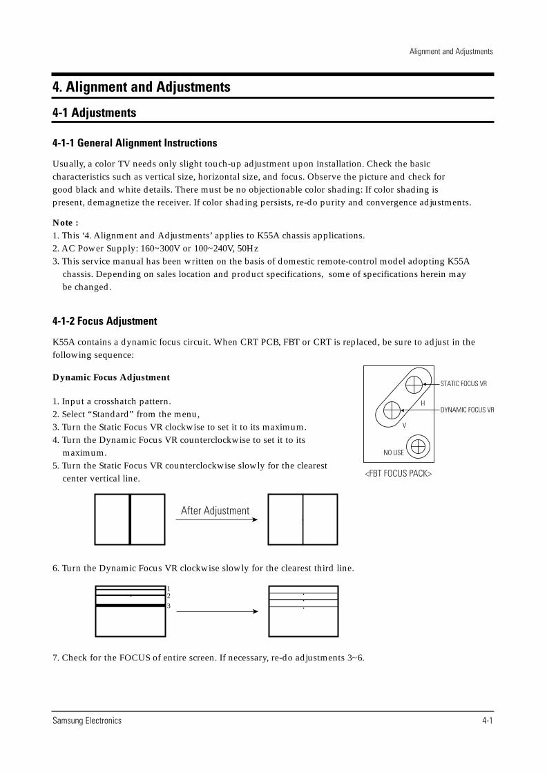
K55A contains a dynamic focus circuit. When CRT PCB, FBT or CRT is replaced, be sure to adjust in thefollowing sequence:
Dynamic Focus Adjustment
1. Input a crosshatch pattern.2. Select “Standard” from the menu,3. Turn the Static Focus VR clockwise to set it to its maximum.4. Turn the Dynamic Focus VR counterclockwise to set it to its
maximum. 5. Turn the Static Focus VR counterclockwise slowly for the clearest
center vertical line.
6. Turn the Dynamic Focus VR clockwise slowly for the clearest third line.
7. Check for the FOCUS of entire screen. If necessary, re-do adjustments 3~6.
After Adjustment
12
3
Alignment and Adjustments
4-2 Samsung Electronics
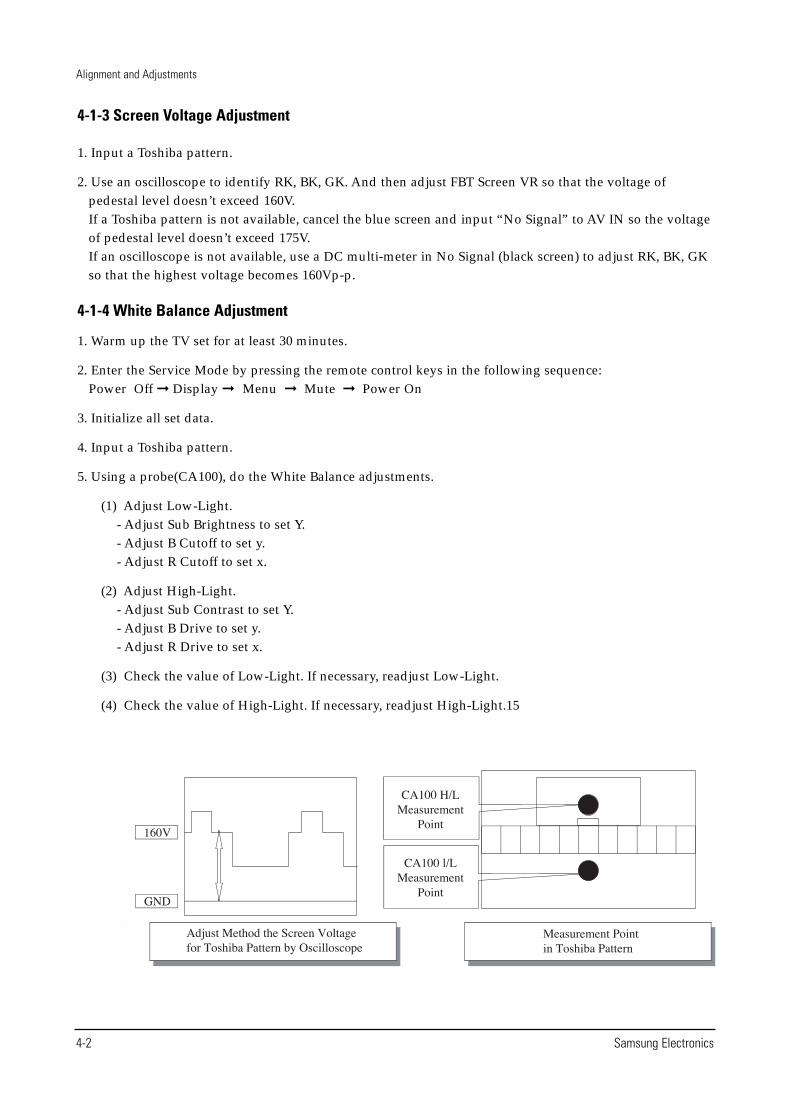
4-1-3 Screen Voltage Adjustment
1. Input a Toshiba pattern.
2. Use an oscilloscope to identify RK, BK, GK. And then adjust FBT Screen VR so that the voltage ofpedestal level doesn’t exceed 160V. If a Toshiba pattern is not available, cancel the blue screen and input “No Signal” to AV IN so the voltageof pedestal level doesn’t exceed 175V.If an oscilloscope is not available, use a DC multi-meter in No Signal (black screen) to adjust RK, BK, GKso that the highest voltage becomes 160Vp-p.
4-1-4 White Balance Adjustment
1. Warm up the TV set for at least 30 minutes.
2. Enter the Service Mode by pressing the remote control keys in the following sequence: Power Off � Display � Menu � Mute � Power On
3. Initialize all set data.
4. Input a Toshiba pattern.
5. Using a probe(CA100), do the White Balance adjustments.
(1) Adjust Low-Light.- Adjust Sub Brightness to set Y.- Adjust B Cutoff to set y.- Adjust R Cutoff to set x.
(2) Adjust High-Light.- Adjust Sub Contrast to set Y.- Adjust B Drive to set y.- Adjust R Drive to set x.
(3) Check the value of Low-Light. If necessary, readjust Low-Light.
(4) Check the value of High-Light. If necessary, readjust High-Light.15
Alignment and Adjustments
Samsung Electronics 4-3
4-1-5 When adjusting Screen Voltage and White Balance
1. Screen Voltage and White Balance are related each other. Make sure both adjustments are correct.
2. Adjust Screen Voltage before White Balance Adjustments. Make sure Screen Voltage is correct.
3. If White Balance has been readjusted, re-check Screen Voltage.
4. After adjustments are complete, check the following.- If spots appear on the screen after pressing the Power On/Off key, readjust Screen Voltage.- If flyback lines appear on the screen, readjust Screen Voltage.
ASSIGNMENT
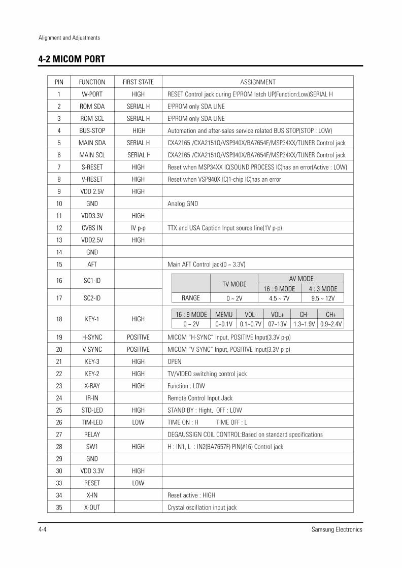
RESET Control jack during E2PROM latch UP(Function:Low)SERIAL H
E2PROM only SDA LINE
E2PROM only SDA LINE
Automation and after-sales service related BUS STOP(STOP : LOW)
CXA2165 /CXA2151Q/VSP940X/BA7654F/MSP34XX/TUNER Control jack
CXA2165 /CXA2151Q/VSP940X/BA7654F/MSP34XX/TUNER Control jack
Reset when MSP34XX IC(SOUND PROCESS IC)has an error(Active : LOW)
Reset when VSP940X IC(1-chip IC)has an error
Analog GND
TTX and USA Caption Input source line(1V p-p)
Main AFT Control jack(0 ~ 3.3V)
MICOM “H-SYNC” Input, POSITIVE Input(3.3V p-p)
MICOM “V-SYNC” Input, POSITIVE Input(3.3V p-p)
OPEN
TV/VIDEO switching control jack
Function : LOW
Remote Control Input Jack
STAND BY : Hight, OFF : LOW
TIME ON : H TIME OFF : L
DEGAUSSIGN COIL CONTROL:Based on standard specifications
H : IN1, L : IN2(BA7657F) PIN(#16) Control jack
Reset active : HIGH
Crystal oscillation input jack
Alignment and Adjustments
4-4 Samsung Electronics
4-2 MICOM PORT
PIN
1
2
3
4
5
6
7
8
9
10
11
12
13
14
15
16
17
18
19
20
21
22
23
24
25
26
27
28
29
30
33
34
35
FUNCTION
W-PORT
ROM SDA
ROM SCL
BUS-STOP
MAIN SDA
MAIN SCL
S-RESET
V-RESET
VDD 2.5V
GND
VDD3.3V
CVBS IN
VDD2.5V
GND
AFT
SC1-ID
SC2-ID
KEY-1
H-SYNC
V-SYNC
KEY-3
KEY-2
X-RAY
IR-IN
STD-LED
TIM-LED
RELAY
SW1
GND
VDD 3.3V
RESET
X-IN
X-OUT
FIRST STATE
HIGH
SERIAL H
SERIAL H
HIGH
SERIAL H
SERIAL H
HIGH
HIGH
HIGH
HIGH
IV p-p
HIGH
HIGH
POSITIVE
POSITIVE
HIGH
HIGH
HIGH
HIGH
LOW
HIGH
HIGH
LOW
RANGE
TV MODE
0 ~ 2V16 : 9 MODE
4.5 ~ 7V4 : 3 MODE9.5 ~ 12V
AV MODE
16 : 9 MODE0 ~ 2V
MEMU0~0.1V
VOL-0.1~0.7V
VOL+07~13V
CH-1.3~1.9V
CH+0.9~2.4V
Alignment and Adjustments
Samsung Electronics 4-5
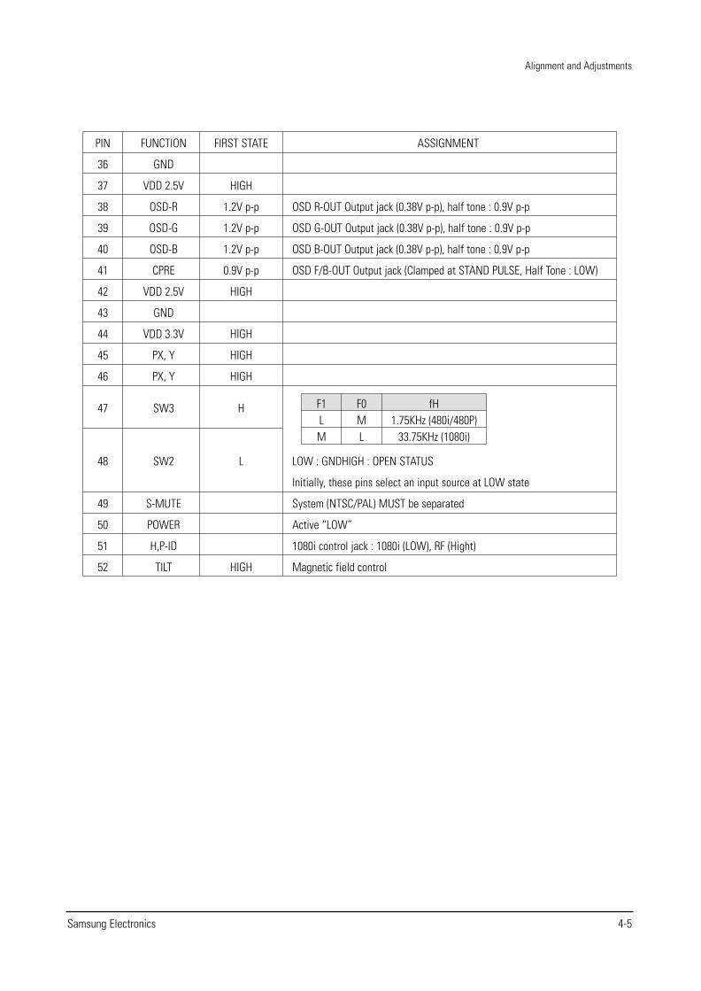
ASSIGNMENT
OSD R-OUT Output jack (0.38V p-p), half tone : 0.9V p-p
OSD G-OUT Output jack (0.38V p-p), half tone : 0.9V p-p
OSD B-OUT Output jack (0.38V p-p), half tone : 0.9V p-p
OSD F/B-OUT Output jack (Clamped at STAND PULSE, Half Tone : LOW)
LOW : GNDHIGH : OPEN STATUS
Initially, these pins select an input source at LOW state
System (NTSC/PAL) MUST be separated
Active “LOW”
1080i control jack : 1080i (LOW), RF (Hight)
Magnetic field control
PIN
36
37
38
39
40
41
42
43
44
45
46
47
48
49
50
51
52
FUNCTION
GND
VDD 2.5V
OSD-R
OSD-G
OSD-B
CPRE
VDD 2.5V
GND
VDD 3.3V
PX, Y
PX, Y
SW3
SW2
S-MUTE
POWER
H,P-ID
TILT
FIRST STATE
HIGH
1.2V p-p
1.2V p-p
1.2V p-p
0.9V p-p
HIGH
HIGH
HIGH
HIGH
H
L
HIGH
F1LM
F0ML
fH1.75KHz (480i/480P)
33.75KHz (1080i)
Alignment and Adjustments
4-6 Samsung Electronics
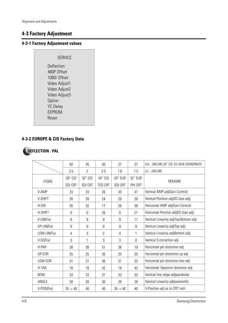
4-3 Factory Adjustment
4-3-1 Factory Adjustment values
SERVICE
Deflection480P Offset1080i OffsetVideo Adjust1Video Adjust2Video Adjust3OptionYC DelayEEPROMReset
4-3-2 EUROPE & CIS Factory Data
ITEMS
V-AMP
V-SHIFT
H-EW
H-SHIFT
V-LIN(Fix)
UP-LIN(Fix)
LOW-LIN(Fix)
V-SC(Fix)
H-PAR
UP-COR
LOW-COR
H-TRA
BOW
ANGLE
V-POSI(Fix)
50
2.5
29” CIS
SDI CRT
33
28
26
0
9
9
4
3
38
25
31
18
33
28
35 -> 40
45
2
32” CIS
SDI CRT
33
28
32
0
9
9
3
1
38
25
31
18
33
28
40
50
2.5
34” CIS
TOS CRT
26
24
17
26
9
9
2
3
51
35
36
42
31
30
40
37
1.8
29” EUR
SDI CRT
33
28
26
0
9
9
4
3
38
25
31
18
33
28
35 -> 40
37
1.5
32” EUR
PHI CRT
41
26
36
21
11
9
1
0
19
33
33
43
33
28
40
H/L : 285/285 29” CIS, EU W/B COORDINATE
L/L : 285/285
REMARK
Vertical AMP adj(Gain Control)
Vertical Position adj(DC bias adj)
Horizontal AMP adj(Gain Control)
Horizontal Position adj(DC bias adj)
Vertical Linearity adj(Top/Bottom adj)
Vertical Linearity adj(Top adj)
Vertical Linearity adj(Bottom adj)
Vertical S correction adj
Horizontal pin distortion adj
Horizontal pin distortion up adj
Horizontal pin distortion low adj
Horizontal Tapezium distortion adj
Vertical line slope adj(parabola)
Vertical Linearity adj(sawtooth)
V-Position adj as to CRT inch
DEFLECTION : PAL
Alignment and Adjustments
Samsung Electronics 4-7
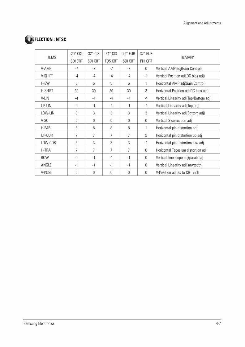
ITEMS
V-AMP
V-SHIFT
H-EW
H-SHIFT
V-LIN
UP-LIN
LOW-LIN
V-SC
H-PAR
UP-COR
LOW-COR
H-TRA
BOW
ANGLE
V-POSI
29” CIS
SDI CRT
-7
-4
5
30
-4
-1
3
0
8
7
3
7
-1
-1
0
32” CIS
SDI CRT
-7
-4
5
30
-4
-1
3
0
8
7
3
7
-1
-1
0
34” CIS
TOS CRT
-7
-4
5
30
-4
-1
3
0
8
7
3
7
-1
-1
0
29” EUR
SDI CRT
-7
-4
5
30
-4
-1
3
0
8
7
3
7
-1
-1
0
32” EUR
PHI CRT
0
-1
1
3
-4
-1
3
0
1
2
-1
0
0
0
0
REMARK
Vertical AMP adj(Gain Control)
Vertical Position adj(DC bias adj)
Horizontal AMP adj(Gain Control)
Horizontal Position adj(DC bias adj)
Vertical Linearity adj(Top/Bottom adj)
Vertical Linearity adj(Top adj)
Vertical Linearity adj(Bottom adj)
Vertical S correction adj
Horizontal pin distortion adj
Horizontal pin distortion up adj
Horizontal pin distortion low adj
Horizontal Tapezium distortion adj
Vertical line slope adj(parabola)
Vertical Linearity adj(sawtooth)
V-Position adj as to CRT inch
DEFLECTION : NTSC
Alignment and Adjustments
4-8 Samsung Electronics
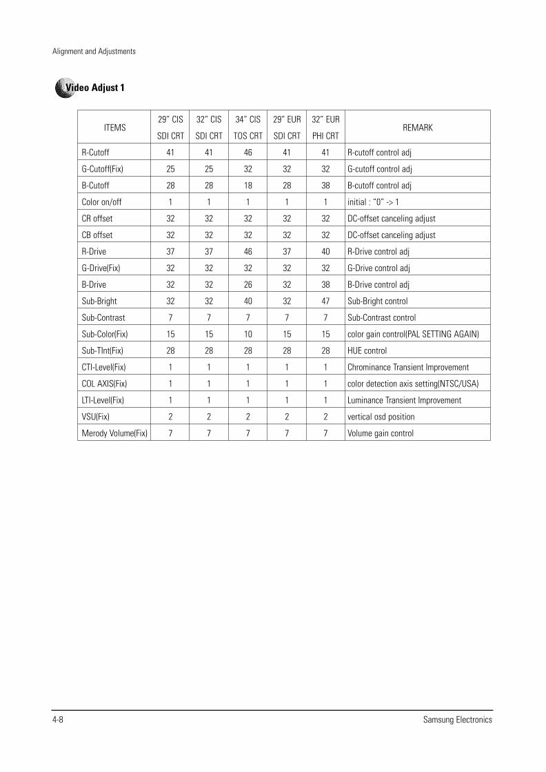
ITEMS
R-Cutoff
G-Cutoff(Fix)
B-Cutoff
Color on/off
CR offset
CB offset
R-Drive
G-Drive(Fix)
B-Drive
Sub-Bright
Sub-Contrast
Sub-Color(Fix)
Sub-TInt(Fix)
CTI-Level(Fix)
COL AXIS(Fix)
LTI-Level(Fix)
VSU(Fix)
Merody Volume(Fix)
29” CIS
SDI CRT
41
25
28
1
32
32
37
32
32
32
7
15
28
1
1
1
2
7
32” CIS
SDI CRT
41
25
28
1
32
32
37
32
32
32
7
15
28
1
1
1
2
7
34” CIS
TOS CRT
46
32
18
1
32
32
46
32
26
40
7
10
28
1
1
1
2
7
29” EUR
SDI CRT
41
32
28
1
32
32
37
32
32
32
7
15
28
1
1
1
2
7
32” EUR
PHI CRT
41
32
38
1
32
32
40
32
38
47
7
15
28
1
1
1
2
7
REMARK
R-cutoff control adj
G-cutoff control adj
B-cutoff control adj
initial : “0” -> 1
DC-offset canceling adjust
DC-offset canceling adjust
R-Drive control adj
G-Drive control adj
B-Drive control adj
Sub-Bright control
Sub-Contrast control
color gain control(PAL SETTING AGAIN)
HUE control
Chrominance Transient Improvement
color detection axis setting(NTSC/USA)
Luminance Transient Improvement
vertical osd position
Volume gain control
Video Adjust 1
Alignment and Adjustments
Samsung Electronics 4-9
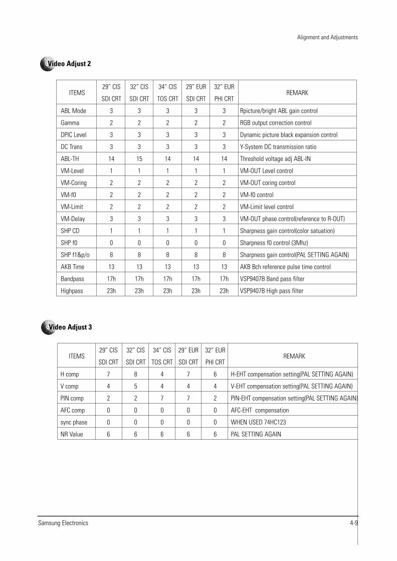
ITEMS
ABL Mode
Gamma
DPIC Level
DC Trans
ABL-TH
VM-Level
VM-Coring
VM-f0
VM-Limit
VM-Delay
SHP CD
SHP f0
SHP f1&p/o
AKB Time
Bandpass
Highpass
29” CIS
SDI CRT
3
2
3
3
14
1
2
2
2
3
1
0
8
13
17h
23h
32” CIS
SDI CRT
3
2
3
3
15
1
2
2
2
3
1
0
8
13
17h
23h
34” CIS
TOS CRT
3
2
3
3
14
1
2
2
2
3
1
0
8
13
17h
23h
29” EUR
SDI CRT
3
2
3
3
14
1
2
2
2
3
1
0
8
13
17h
23h
32” EUR
PHI CRT
3
2
3
3
14
1
2
2
2
3
1
0
8
13
17h
23h
REMARK
Rpicture/bright ABL gain control
RGB output correction control
Dynamic picture black expansion control
Y-System DC transmission ratio
Threshold voltage adj ABL-IN
VM-OUT Level control
VM-OUT coring control
VM-f0 control
VM-Limit level control
VM-OUT phase control(reference to R-OUT)
Sharpness gain control(color satuation)
Sharpness f0 control (3Mhz)
Sharpness gain control(PAL SETTING AGAIN)
AKB Bch reference pulse time control
VSP9407B Band pass filter
VSP9407B High pass filter
Video Adjust 2
ITEMS
H comp
V comp
PIN comp
AFC comp
sync phase
NR Value
29” CIS
SDI CRT
7
4
2
0
0
6
32” CIS
SDI CRT
8
5
2
0
0
6
34” CIS
TOS CRT
4
4
7
0
0
6
29” EUR
SDI CRT
7
4
7
0
0
6
32” EUR
PHI CRT
6
4
2
0
0
6
REMARK
H-EHT compensation setting(PAL SETTING AGAIN)
V-EHT compensation setting(PAL SETTING AGAIN)
PIN-EHT compensation setting(PAL SETTING AGAIN)
AFC-EHT compensation
WHEN USED 74HC123
PAL SETTING AGAIN
Video Adjust 3
Alignment and Adjustments
4-10 Samsung Electronics
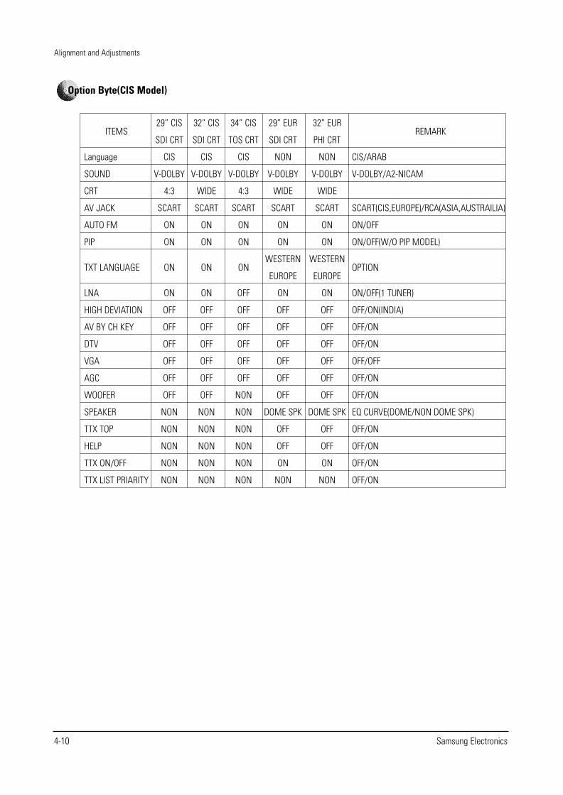
ITEMS
Language
SOUND
CRT
AV JACK
AUTO FM
PIP
TXT LANGUAGE
LNA
HIGH DEVIATION
AV BY CH KEY
DTV
VGA
AGC
WOOFER
SPEAKER
TTX TOP
HELP
TTX ON/OFF
TTX LIST PRIARITY
29” CIS
SDI CRT
CIS
V-DOLBY
4:3
SCART
ON
ON
ON
ON
OFF
OFF
OFF
OFF
OFF
OFF
NON
NON
NON
NON
NON
32” CIS
SDI CRT
CIS
V-DOLBY
WIDE
SCART
ON
ON
ON
ON
OFF
OFF
OFF
OFF
OFF
OFF
NON
NON
NON
NON
NON
34” CIS
TOS CRT
CIS
V-DOLBY
4:3
SCART
ON
ON
ON
OFF
OFF
OFF
OFF
OFF
OFF
NON
NON
NON
NON
NON
NON
29” EUR
SDI CRT
NON
V-DOLBY
WIDE
SCART
ON
ON
WESTERN
EUROPE
ON
OFF
OFF
OFF
OFF
OFF
OFF
DOME SPK
OFF
OFF
ON
NON
32” EUR
PHI CRT
NON
V-DOLBY
WIDE
SCART
ON
ON
WESTERN
EUROPE
ON
OFF
OFF
OFF
OFF
OFF
OFF
DOME SPK
OFF
OFF
ON
NON
REMARK
CIS/ARAB
V-DOLBY/A2-NICAM
SCART(CIS,EUROPE)/RCA(ASIA,AUSTRAILIA)
ON/OFF
ON/OFF(W/O PIP MODEL)
OPTION
ON/OFF(1 TUNER)
OFF/ON(INDIA)
OFF/ON
OFF/ON
OFF/OFF
OFF/ON
OFF/ON
EQ CURVE(DOME/NON DOME SPK)
OFF/ON
OFF/ON
OFF/ON
OFF/ON
Option Byte(CIS Model)
Alignment and Adjustments
Samsung Electronics 4-11
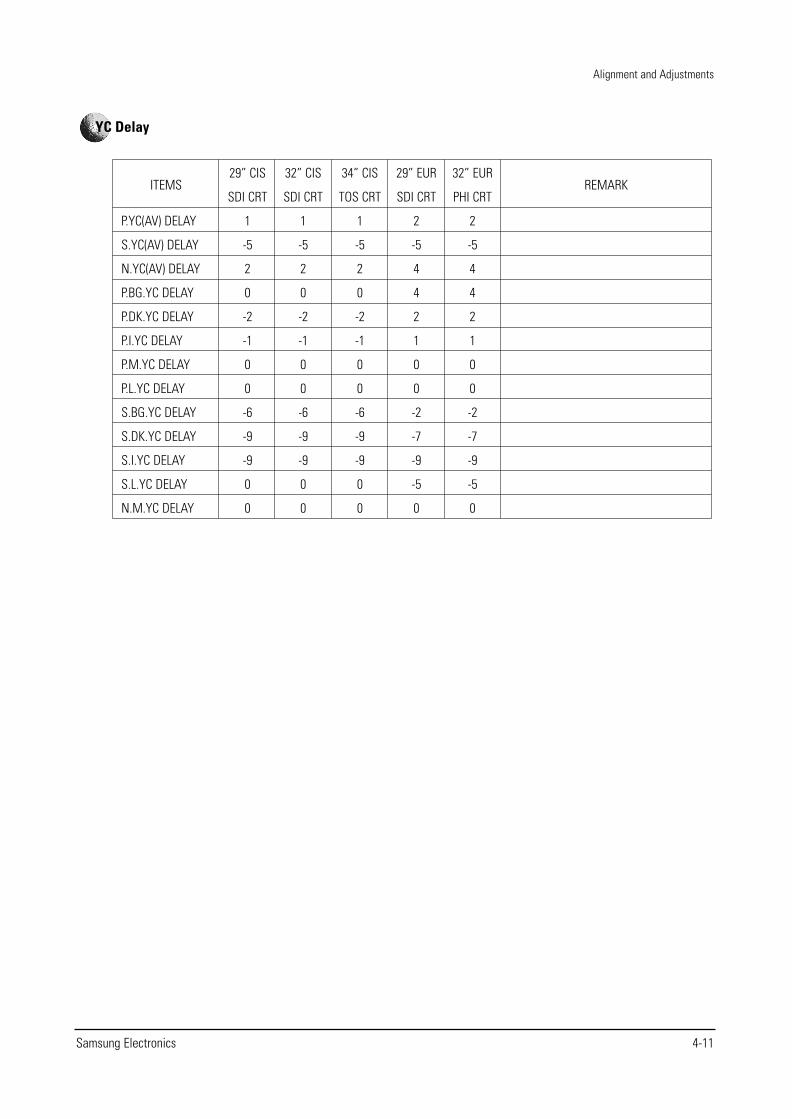
ITEMS
P.YC(AV) DELAY
S.YC(AV) DELAY
N.YC(AV) DELAY
P.BG.YC DELAY
P.DK.YC DELAY
P.I.YC DELAY
P.M.YC DELAY
P.L.YC DELAY
S.BG.YC DELAY
S.DK.YC DELAY
S.I.YC DELAY
S.L.YC DELAY
N.M.YC DELAY
29” CIS
SDI CRT
1
-5
2
0
-2
-1
0
0
-6
-9
-9
0
0
32” CIS
SDI CRT
1
-5
2
0
-2
-1
0
0
-6
-9
-9
0
0
34” CIS
TOS CRT
1
-5
2
0
-2
-1
0
0
-6
-9
-9
0
0
29” EUR
SDI CRT
2
-5
4
4
2
1
0
0
-2
-7
-9
-5
0
32” EUR
PHI CRT
2
-5
4
4
2
1
0
0
-2
-7
-9
-5
0
REMARK
YC Delay
Alignment and Adjustments
4-12 Samsung Electronics
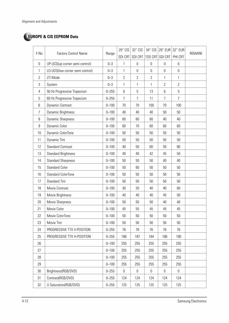
Factory Control Name
UP-UCG(up corner semi control)
LO-UCG(low corner semi control)
LTI Mode
System
50 Hz Progressive Trapezium
60 Hz Progressive Trapezium
Dynamic Contrast
Dynamic Brightness
Dynamic Sharpness
Dynamic Color
Dynamic ColorTone
Dynamic Tint
Standard Contrast
Standard Brightness
Standard Sharpness
Standard Color
Standard ColorTone
Standard Tint
Movie Contrast
Movie Brightness
Movie Sharpness
Movie Color
Movie ColorTone
Movie Tint
PROGRESSIVE TTX V-POSITION
PROGRESSIVE TTX H-POSITION
Brightness(RGB/DVD)
Contrast(RGB/DVD)
U Saturation(RGB/DVD)
F-No
0
1
2
3
4
5
6
7
8
9
10
11
12
13
14
15
16
17
18
19
20
21
22
23
24
25
26
27
28
29
30
31
32
Range
0~3
0~3
0~3
0~3
0~255
0~255
0~100
0~100
0~100
0~100
0~100
0~100
0~100
0~100
0~100
0~100
0~100
0~100
0~100
0~100
0~100
0~100
0~100
0~100
0~255
0~255
0~100
0~100
0~100
0~100
0~255
0~255
0~255
29” CIS
SDI CRT
1
1
2
1
6
7
70
40
60
60
50
50
40
40
50
50
50
50
30
40
50
45
50
50
76
186
255
255
255
255
0
124
125
32” CIS
SDI CRT
0
0
2
1
5
7
70
40
60
70
50
50
50
40
50
60
50
50
35
40
50
55
50
50
78
187
255
255
255
255
0
124
125
34” CIS
TOS CRT
0
0
2
1
13
11
100
40
60
60
50
50
60
42
50
50
50
50
40
40
50
45
50
50
76
184
255
255
255
255
0
124
125
29” EUR
SDI CRT
0
0
1
2
6
7
70
50
40
60
50
50
50
45
40
50
50
50
40
45
40
45
50
50
76
186
255
255
255
255
0
124
125
32” EUR
PHI CRT
0
0
1
2
5
7
100
50
40
60
50
50
80
50
40
50
50
50
60
50
40
45
50
50
76
190
255
255
255
255
0
124
125
REMARK
EUROPE & CIS EEPROM Data
Alignment and Adjustments
Samsung Electronics 4-13
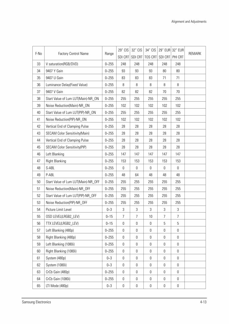
Factory Control Name
V saturation(RGB/DVD)
9407 Y Gain
9407 U Gain
Luminance Delay(Fixed Value)
9407 V Gain
Start Value of Lum LUT(Main)-NR_ON
Noise Reduction(Main)-NR_ON
Start Value of Lum LUT(PIP)-NR_ON
Noise Reduction(PIP)-NR_ON
Vertical End of Clamping Pulse
SECAM Color Sensitivity(Main)
Vertical End of Clamping Pulse
SECAM Color Sensitivity(PIP)
Left Blanking
Right Blanking
S-ABL
P-ABL
Start Value of Lum LUT(Main)-NR_OFF
Noise Reduction(Main)-NR_OFF
Start Value of Lum LUT(PIP)-NR_OFF
Noise Reduction(PIP)-NR_OFF
Picture Limit Level
OSD LEVEL(LRGB2_LEV)
TTX LEVEL(LRGB2_LEV)
Left Blanking (480p)
Right Blanking (480p)
Left Blanking (1080i)
Right Blanking (1080i)
System (480p)
System (1080i)
CrCb Gain (480p)
CrCb Gain (1080i)
LTI Mode (480p)
F-No
33
34
35
36
37
38
39
40
41
42
43
44
45
46
47
48
49
50
51
52
53
54
55
56
57
58
59
60
61
62
63
64
65
Range
0~255
0~255
0~255
0~255
0~255
0~255
0~255
0~255
0~255
0~255
0~255
0~255
0~255
0~255
0~255
0~255
0~255
0~255
0~255
0~255
0~255
0~3
0~15
0~15
0~255
0~255
0~255
0~255
0~3
0~3
0~255
0~255
0~3
29” CIS
SDI CRT
248
93
83
8
82
255
102
255
102
28
28
28
28
147
153
0
48
255
255
255
255
3
7
0
0
0
0
0
0
0
0
0
0
32” CIS
SDI CRT
248
93
83
8
82
255
102
255
102
28
28
28
28
147
153
0
64
255
255
255
255
3
7
0
0
0
0
0
0
0
0
0
0
34” CIS
TOS CRT
248
93
83
8
82
255
102
255
102
28
28
28
28
147
153
0
48
255
255
255
255
3
10
0
0
0
0
0
0
0
0
0
0
29” EUR
SDI CRT
248
80
71
8
70
255
102
255
102
28
28
28
28
147
153
0
48
255
255
255
255
3
7
5
0
0
0
0
0
0
0
0
0
32” EUR
PHI CRT
248
80
71
8
70
255
102
255
102
28
28
28
28
147
153
0
48
255
255
255
255
3
7
5
0
0
0
0
0
0
0
0
0
REMARK
Alignment and Adjustments
4-14 Samsung Electronics
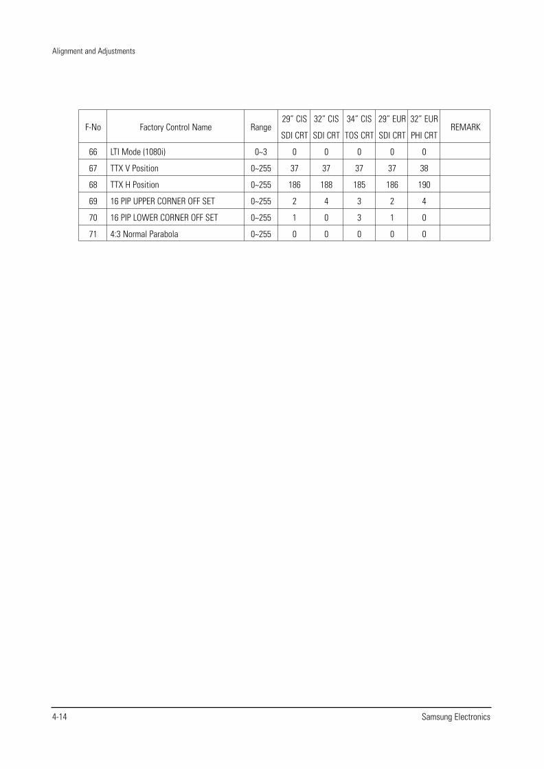
Factory Control Name
LTI Mode (1080i)
TTX V Position
TTX H Position
16 PIP UPPER CORNER OFF SET
16 PIP LOWER CORNER OFF SET
4:3 Normal Parabola
F-No
66
67
68
69
70
71
Range
0~3
0~255
0~255
0~255
0~255
0~255
29” CIS
SDI CRT
0
37
186
2
1
0
32” CIS
SDI CRT
0
37
188
4
0
0
34” CIS
TOS CRT
0
37
185
3
3
0
29” EUR
SDI CRT
0
37
186
2
1
0
32” EUR
PHI CRT
0
38
190
4
0
0
REMARK
Alignment and Adjustments
Samsung Electronics 4-15
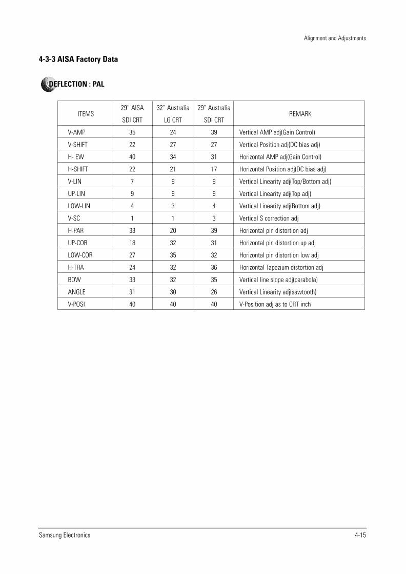
4-3-3 AISA Factory Data
ITEMS
V-AMP
V-SHIFT
H- EW
H-SHIFT
V-LIN
UP-LIN
LOW-LIN
V-SC
H-PAR
UP-COR
LOW-COR
H-TRA
BOW
ANGLE
V-POSI
29” AISA
SDI CRT
35
22
40
22
7
9
4
1
33
18
27
24
33
31
40
32” Australia
LG CRT
24
27
34
21
9
9
3
1
20
32
35
32
32
30
40
29” Australia
SDI CRT
39
27
31
17
9
9
4
3
39
31
32
36
35
26
40
REMARK
Vertical AMP adj(Gain Control)
Vertical Position adj(DC bias adj)
Horizontal AMP adj(Gain Control)
Horizontal Position adj(DC bias adj)
Vertical Linearity adj(Top/Bottom adj)
Vertical Linearity adj(Top adj)
Vertical Linearity adj(Bottom adj)
Vertical S correction adj
Horizontal pin distortion adj
Horizontal pin distortion up adj
Horizontal pin distortion low adj
Horizontal Tapezium distortion adj
Vertical line slope adj(parabola)
Vertical Linearity adj(sawtooth)
V-Position adj as to CRT inch
DEFLECTION : PAL
Alignment and Adjustments
4-16 Samsung Electronics
ITEMS
V-AMP
V-SHIFT
H- EW
H-SHIFT
V-LIN
UP-LIN
LOW-LIN
V-SC
H-PAR
UP-COR
LOW-COR
H-TRA
BOW
ANGLE
V-POSI
29” AISA
SDI CRT
-1
1
8
-9
0
0
0
0
0
0
0
-7
0
0
0
32” Australia
LG CRT
2
-3
4
-7
-4
-1
3
0
-4
3
-3
4
0
1
0
29” Australia
SDI CRT
-8
2
3
-9
0
-1
-3
2
1
-1
-1
3
2
0
0
REMARK
Vertical AMP adj( Gain Control)
Vertical Position adj (DC bias adj)
Horizontal AMP adj(Gain Control)
Horizontal Position adj (DC bias adj)
Vertical Linearity adj(TOP/Bottom adj)
Vertical Linearity adj(TOP adj)
Vertical Linearity adj(Bottom adj)
Vertical S correction adj
Horizontal pin distortion adj
Horizontal pin distortion up adj
Horizontal pin distortion low adj
Horizontal Trapezium distortion adj
Vertical line slope adj(parabola)
Vertical Linearity adj(sawtooth)
V-POSITION ADJ as to CRT INCH
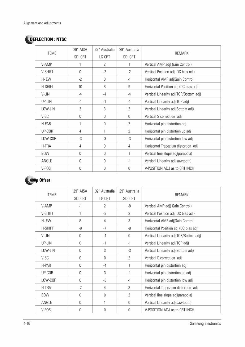
480p Offset
ITEMS
V-AMP
V-SHIFT
H- EW
H-SHIFT
V-LIN
UP-LIN
LOW-LIN
V-SC
H-PAR
UP-COR
LOW-COR
H-TRA
BOW
ANGLE
V-POSI
29” AISA
SDI CRT
1
0
-2
10
-4
-1
2
0
1
4
-3
4
0
0
0
32” Australia
LG CRT
2
-2
0
8
-4
-1
3
0
0
1
-3
0
0
0
0
29” Australia
SDI CRT
1
-2
-1
9
-4
-1
2
0
2
2
-3
4
1
-1
0
REMARK
Vertical AMP adj( Gain Control)
Vertical Position adj (DC bias adj)
Horizontal AMP adj(Gain Control)
Horizontal Position adj (DC bias adj)
Vertical Linearity adj(TOP/Bottom adj)
Vertical Linearity adj(TOP adj)
Vertical Linearity adj(Bottom adj)
Vertical S correction adj
Horizontal pin distortion adj
Horizontal pin distortion up adj
Horizontal pin distortion low adj
Horizontal Trapezium distortion adj
Vertical line slope adj(parabola)
Vertical Linearity adj(sawtooth)
V-POSITION ADJ as to CRT INCH
DEFLECTION : NTSC
Alignment and Adjustments
Samsung Electronics 4-17
ITEMS
V-AMP
V-SHIFT
H- EW
H-SHIFT
V-LIN
UP-LIN
LOW-LIN
V-SC
H-PAR
UP-COR
LOW-COR
H-TRA
BOW
ANGLE
V-POSI
29” AISA
SDI CRT
-14
2
6
4
0
0
0
0
0
0
0
0
0
0
0
32” Australia
LG CRT
-1
-2
-10
11
0
0
0
0
3
5
3
2
-1
1
0
29” Australia
SDI CRT
-4
-1
2
10
-1
0
-1
0
-1
0
1
-3
1
2
0
REMARK
Vertical AMP adj( Gain Control)
Vertical Position adj (DC bias adj)
Horizontal AMP adj(Gain Control)
Horizontal Position adj (DC bias adj)
Vertical Linearity adj(TOP/Bottom adj)
Vertical Linearity adj(TOP adj)
Vertical Linearity adj(Bottom adj)
Vertical S correction adj
Horizontal pin distortion adj
Horizontal pin distortion up adj
Horizontal pin distortion low adj
Horizontal Trapezium distortion adj
Vertical line slope adj(parabola)
Vertical Linearity adj(sawtooth)
V-POSITION ADJ as to CRT INCH
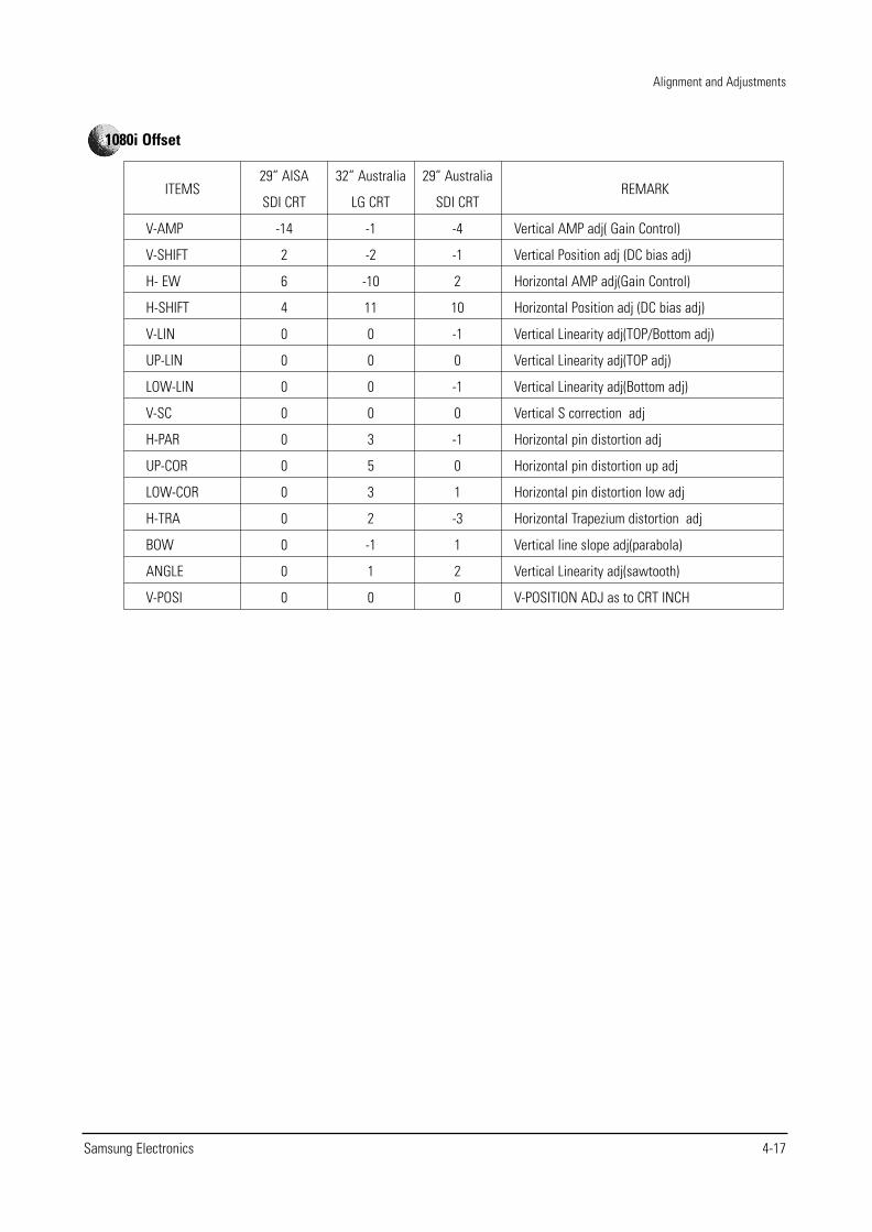
1080i Offset
Alignment and Adjustments
4-18 Samsung Electronics
ITEMS
R-Cutoff
G-Cutoff
B-Cutoff
Color on/off
CR offset
CB offset
R-Drive
G-Drive
B-Drive
Sub-Bright
Sub-Contrast
Sub-Color
Sub-Tint
CTI-Level
COL AXIS
LTI-Level
VSU
Merody Volume
29” AISA
SDI CRT
41
32
28
1
32
32
37
32
32
32
7
15
28
1
1
1
2
4
32” Australia
LG CRT
31
32
43
1
32
32
37
32
43
33
7
15
28
1
1
1
2
4
29” Australia
SDI CRT
41
32
28
1
32
32
37
32
32
32
7
15
28
1
1
1
2
4
REMARK
R-cutoff control adj
G-cutoff control adj
B-cutoff control adj
Fixed :"0"--> 1
DC-offset canceling adjust
DC-offset canceling adjust
R-Drive control adj
G-Drive control adj
B-Drive control adj
Sub-Bright control
Sub-Contrast control
color gain control(PAL SETTING AGAIN)
HUE control
Chrominance Transient Improvement
color detection axis setting(NTSC/USA)
Luminance Transient Improvement
vertical osd position
Volume gain control
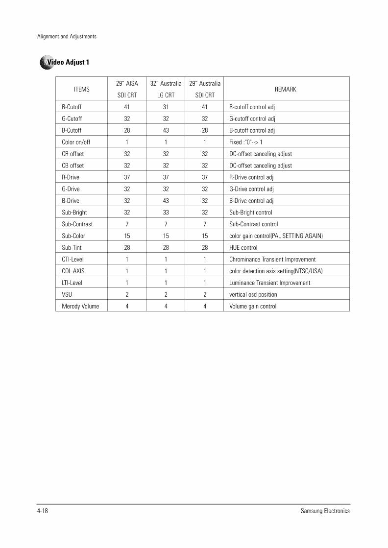
Video Adjust 1
Alignment and Adjustments
Samsung Electronics 4-19
ITEMS
ABL Mode
Gamma
DPIC Level
DC Trans
ABL-TH
VM-Level
VM-Coring
VM-f0
VM-Limit
VM-Delay
SHP CD
SHP f0
SHP f1&p/o
AKB Time
Bandpass
Highpass
29” AISA
SDI CRT
3
2
3
3
14
1
2
2
2
3
1
0
8
13
17
23
32” Australia
LG CRT
3
2
3
3
15
1
2
2
2
3
1
0
8
13
17
23
29” Australia
SDI CRT
3
2
3
3
14
1
2
2
2
3
1
0
8
13
17
23
REMARK
picture/bright ABL gain control
RGB output correction control
Dynamic picture black expansion control
Y-System DC transmission ratio
Threshold voltage adj ABL-IN
VM-OUT Level control
VM-OUT coring control
VM-f0 control
VM-Limit level control
VM-OUT phase control(reference to R-OUT)
Sharpness gain control(color satuation)
Sharpness f0 control (3Mhz)
Sharpness gain control(PAL SETTING AGAIN)
AKB Bch reference pulse time control
VSP9407B Band pass filter
VSP9407B High pass filter
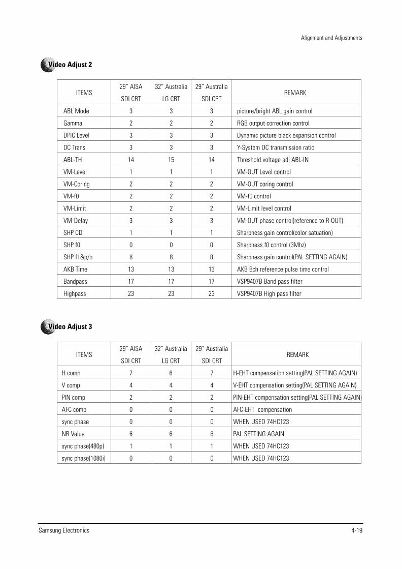
Video Adjust 2
ITEMS
H comp
V comp
PIN comp
AFC comp
sync phase
NR Value
sync phase(480p)
sync phase(1080i)
29” AISA
SDI CRT
7
4
2
0
0
6
1
0
32” Australia
LG CRT
6
4
2
0
0
6
1
0
29” Australia
SDI CRT
7
4
2
0
0
6
1
0
REMARK
H-EHT compensation setting(PAL SETTING AGAIN)
V-EHT compensation setting(PAL SETTING AGAIN)
PIN-EHT compensation setting(PAL SETTING AGAIN)
AFC-EHT compensation
WHEN USED 74HC123
PAL SETTING AGAIN
WHEN USED 74HC123
WHEN USED 74HC123
Video Adjust 3
Alignment and Adjustments
4-20 Samsung Electronics
ITEMS
Sub-Bright
Sub-Contrast
Sub-Color
Sub-Tint
COL AXIS
LTI-Level
VM-Level
VM-Coring
VM-f0
VM-Limit
VM-Delay
SHP CD
SHP f0
SHP f1 & p/o
29” AISA
SDI CRT
19
7
15
28
1
2
1
2
2
2
3
1
0
8
32” Australia
LG CRT
38
7
15
28
1
2
1
2
2
2
3
1
0
8
29” Australia
SDI CRT
19
7
15
28
1
1
1
2
2
2
3
1
0
8
REMARK
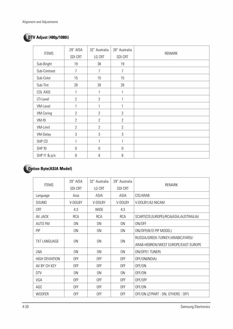
DTV Adjust (480p/1080i)
ITEMS
Language
SOUND
CRT
AV JACK
AUTO FM
PIP
TXT LANGUAGE
LNA
HIGH DEVIATION
AV BY CH KEY
DTV
VGA
AGC
WOOFER
29” AISA
SDI CRT
Asia
V-DOLBY
4:3
RCA
ON
ON
ON
ON
OFF
OFF
ON
OFF
OFF
OFF
32” Australia
LG CRT
ASIA
V-DOLBY
WIDE
RCA
ON
ON
ON
ON
OFF
OFF
ON
OFF
OFF
OFF
29” Australia
SDI CRT
ASIA
V-DOLBY
4:3
RCA
ON
ON
ON
ON
OFF
OFF
ON
OFF
OFF
OFF
REMARK
CIS/ARAB
V-DOLBY/A2-NICAM
SCART(CIS,EUROPE)/RCA(ASIA,AUSTRAILIA)
ON/OFF
ON/OFF(W/O PIP MODEL)
RUSSIA/GREEK-TURKEY/ARABIC/FARSI/
ARAB-HEBREW/WEST EUROPE/EAST EUROPE
ON/OFF(1 TUNER)
OFF/ON(INDIA)
OFF/ON
OFF/ON
OFF/OFF
OFF/ON
OFF/ON (Z7PART : ON, OTHERS : OFF)
Option Byte(ASIA Model)
Alignment and Adjustments
Samsung Electronics 4-21
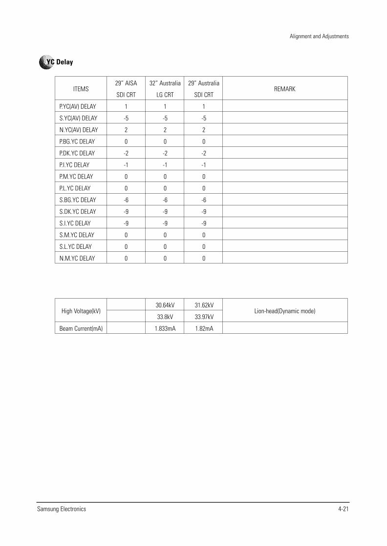
ITEMS
P.YC(AV) DELAY
S.YC(AV) DELAY
N.YC(AV) DELAY
P.BG.YC DELAY
P.DK.YC DELAY
P.I.YC DELAY
P.M.YC DELAY
P.L.YC DELAY
S.BG.YC DELAY
S.DK.YC DELAY
S.I.YC DELAY
S.M.YC DELAY
S.L.YC DELAY
N.M.YC DELAY
29” AISA
SDI CRT
1
-5
2
0
-2
-1
0
0
-6
-9
-9
0
0
0
32” Australia
LG CRT
1
-5
2
0
-2
-1
0
0
-6
-9
-9
0
0
0
29” Australia
SDI CRT
1
-5
2
0
-2
-1
0
0
-6
-9
-9
0
0
0
REMARK
YC Delay
High Voltage(kV)
Beam Current(mA)
30.64kV
33.8kV
1.833mA
31.62kV
33.97kV
1.82mA
Lion-head(Dynamic mode)
Alignment and Adjustments
4-22 Samsung Electronics
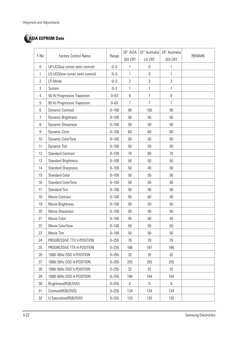
Factory Control Name
UP-UCG(up corner semi control)
LO-UCG(low corner semi control)
LTI Mode
System
50 Hz Progressive Trapezium
60 Hz Progressive Trapezium
Dynamic Contrast
Dynamic Brightness
Dynamic Sharpness
Dynamic Color
Dynamic ColorTone
Dynamic Tint
Standard Contrast
Standard Brightness
Standard Sharpness
Standard Color
Standard ColorTone
Standard Tint
Movie Contrast
Movie Brightness
Movie Sharpness
Movie Color
Movie ColorTone
Movie Tint
PROGRESSIVE TTX V-POSITION
PROGRESSIVE TTX H-POSITION
1080i 50Hz OSD V-POSITION
1080i 50Hz OSD H-POSITION
1080i 60Hz OSD V-POSITION
1080i 60Hz OSD H-POSITION
Brightness(RGB/DVD)
Contrast(RGB/DVD)
U Saturation(RGB/DVD)
F-No
0
1
2
3
4
5
6
7
8
9
10
11
12
13
14
15
16
17
18
19
20
21
22
23
24
25
26
27
28
29
30
31
32
Range
0~3
0~3
0~3
0~3
0~63
0~63
0~100
0~100
0~100
0~100
0~100
0~100
0~100
0~100
0~100
0~100
0~100
0~100
0~100
0~100
0~100
0~100
0~100
0~100
0~255
0~255
0~255
0~255
0~255
0~255
0~255
0~255
0~255
29” AISA
SDI CRT
1
1
2
1
6
7
90
50
50
60
50
50
70
50
50
50
50
50
50
50
50
45
50
50
76
186
32
255
32
184
0
124
125
32” Australia
LG CRT
0
0
2
1
7
7
100
50
50
60
50
50
80
50
40
50
50
50
60
50
40
50
50
50
78
187
32
255
32
184
0
124
125
29” Australia
SDI CRT
1
1
2
1
6
7
90
50
50
60
50
50
70
50
50
50
50
50
50
50
50
45
50
50
76
186
32
255
32
184
0
124
125
REMARK
ASIA EEPROM Data
Alignment and Adjustments
Samsung Electronics 4-23
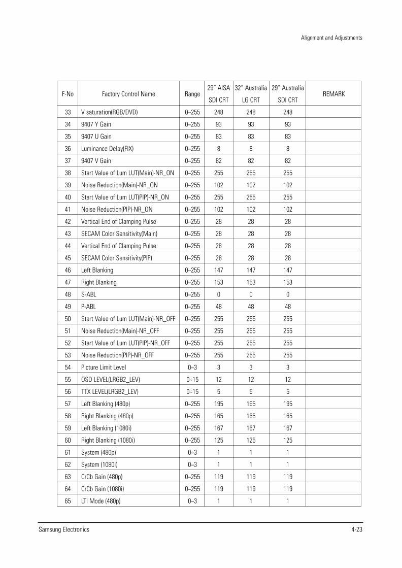
Factory Control Name
V saturation(RGB/DVD)
9407 Y Gain
9407 U Gain
Luminance Delay(FIX)
9407 V Gain
Start Value of Lum LUT(Main)-NR_ON
Noise Reduction(Main)-NR_ON
Start Value of Lum LUT(PIP)-NR_ON
Noise Reduction(PIP)-NR_ON
Vertical End of Clamping Pulse
SECAM Color Sensitivity(Main)
Vertical End of Clamping Pulse
SECAM Color Sensitivity(PIP)
Left Blanking
Right Blanking
S-ABL
P-ABL
Start Value of Lum LUT(Main)-NR_OFF
Noise Reduction(Main)-NR_OFF
Start Value of Lum LUT(PIP)-NR_OFF
Noise Reduction(PIP)-NR_OFF
Picture Limit Level
OSD LEVEL(LRGB2_LEV)
TTX LEVEL(LRGB2_LEV)
Left Blanking (480p)
Right Blanking (480p)
Left Blanking (1080i)
Right Blanking (1080i)
System (480p)
System (1080i)
CrCb Gain (480p)
CrCb Gain (1080i)
LTI Mode (480p)
F-No
33
34
35
36
37
38
39
40
41
42
43
44
45
46
47
48
49
50
51
52
53
54
55
56
57
58
59
60
61
62
63
64
65
Range
0~255
0~255
0~255
0~255
0~255
0~255
0~255
0~255
0~255
0~255
0~255
0~255
0~255
0~255
0~255
0~255
0~255
0~255
0~255
0~255
0~255
0~3
0~15
0~15
0~255
0~255
0~255
0~255
0~3
0~3
0~255
0~255
0~3
29” AISA
SDI CRT
248
93
83
8
82
255
102
255
102
28
28
28
28
147
153
0
48
255
255
255
255
3
12
5
195
165
167
125
1
1
119
119
1
32” Australia
LG CRT
248
93
83
8
82
255
102
255
102
28
28
28
28
147
153
0
48
255
255
255
255
3
12
5
195
165
167
125
1
1
119
119
1
29” Australia
SDI CRT
248
93
83
8
82
255
102
255
102
28
28
28
28
147
153
0
48
255
255
255
255
3
12
5
195
165
167
125
1
1
119
119
1
REMARK
Alignment and Adjustments
4-24 Samsung Electronics
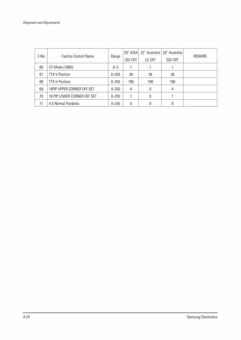
Factory Control Name
LTI Mode (1080i)
TTX V Position
TTX H Position
16PIP UPPER CORNER OFF SET
16 PIP LOWER CORNER OFF SET
4:3 Normal Parabola
F-No
66
67
68
69
70
71
Range
0~3
0~255
0~255
0~255
0~255
0~255
29” AISA
SDI CRT
1
38
186
4
1
0
32” Australia
LG CRT
1
38
188
0
0
0
29” Australia
SDI CRT
1
38
186
4
1
0
REMARK
Alignment and Adjustments
Samsung Electronics 4-25
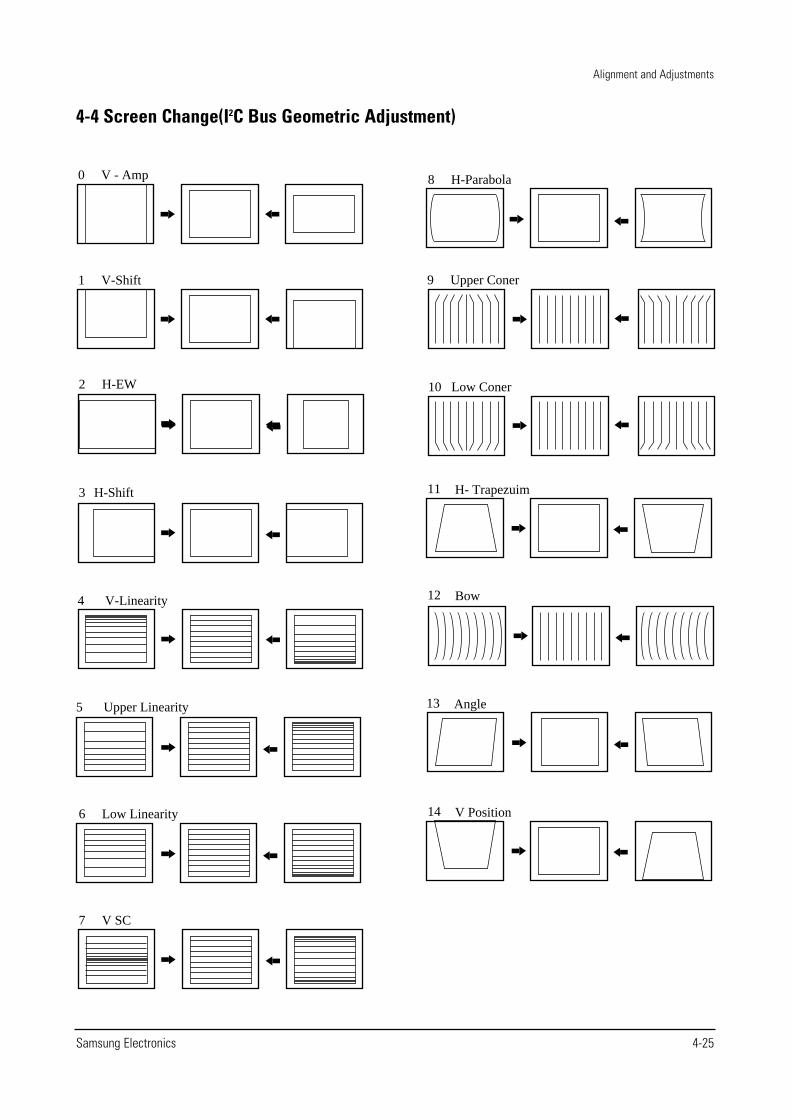
4-4 Screen Change(I2C Bus Geometric Adjustment)
12 Bow4 V-Linearity
5 Upper Linearity
11 H- Trapezuim3 H-Shift
13 Angle
0 V - Amp
9 Upper Coner
10 Low Coner2 H-EW
6 Low Linearity
7 V SC
8 H-Parabola
14 V Position
1 V-Shift
Troubleshooting
Samsung Electronics 5-1
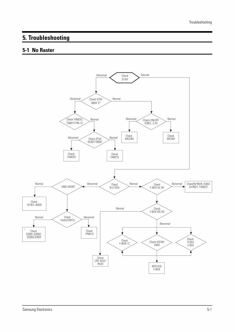
5. Troubleshooting
5-1 No Raster
CheckST-BY
Check ST5VQ804 "E"
Check VIN(DC)TS801S PIN 13
Abnormal
Abnormal
Abnormal
Check FA803S
CheckMICOM
CheckFA801S
Normal
Normal
Normal Normal
Abnormal Normal
Abnormal
Abnormal
Abnormal
AbnormalNormalNormal
Normal
Normal
Check ST5VHC801"D809"
Check ON/OFFIC903 ; 3.3V
Check MICOM
CheckB+(135V)
CheckF-BOX 5V, 9V
CheckF-BOX HD,VD
Check HIC401Q402
CheckF-BOX I C
Check H-BLKV-BLK
Check9V:R829, IC8035V:R827, FA802SGND SHORT
REPLACEF-BOX
Check HC401 J6920
Check DZ801,DZ802, DZ803,IC804
Check Vin(dc)T801S
Check FP801S
CheckCRT ASSY
R529
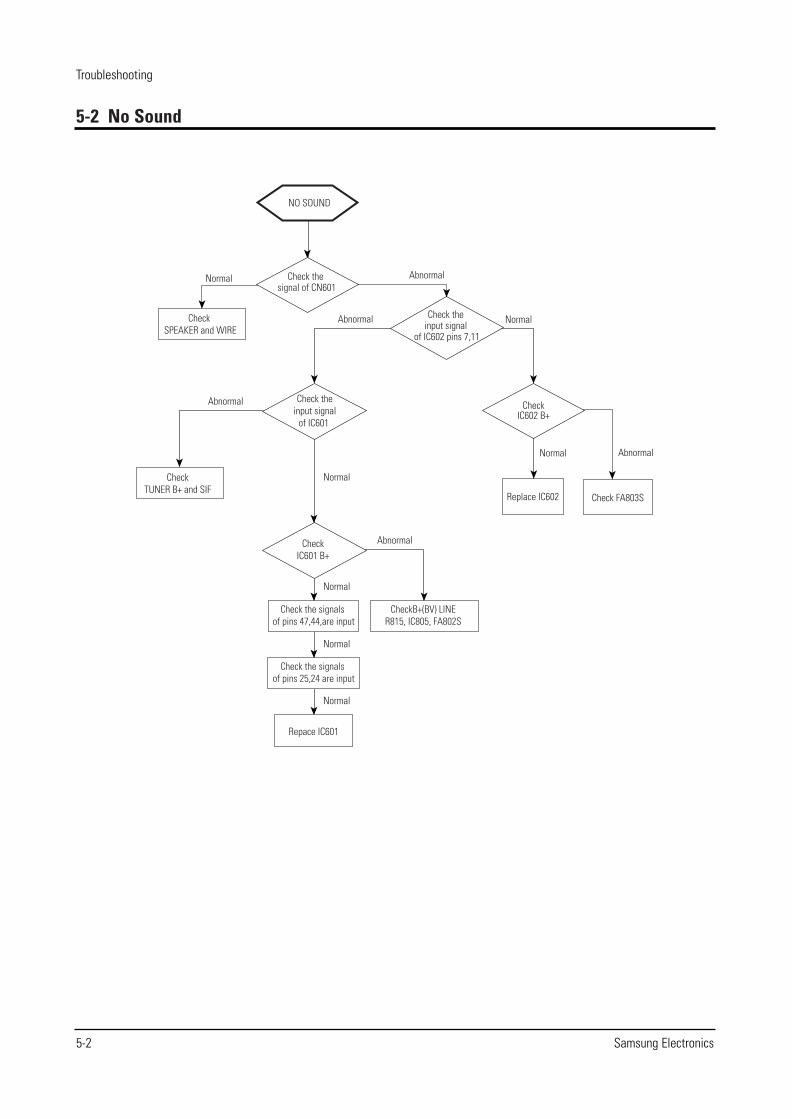
5-2 No Sound
Troubleshooting
5-2 Samsung Electronics
NO SOUND
Check the signal of CN601
Check the input signal
of IC602 pins 7,11
Check the input signal
of IC601
Check SPEAKER and WIRE
Check FA803S Replace IC602
Check IC602 B+
CheckTUNER B+ and SIF
Check IC601 B+
Check the signals of pins 47,44,are input
Check the signals of pins 25,24 are input
Repace IC601
CheckB+(BV) LINE R815, IC805, FA802S
Abnormal
Abnormal
Abnormal
Abnormal
Abnormal
Normal
Normal
Normal
Normal
Normal
Normal
Normal
Troubleshooting
Samsung Electronics 5-3
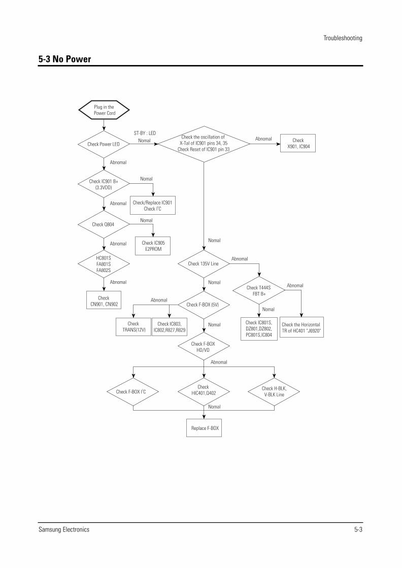
5-3 No Power
Plug in the Power Cord
Check Power LED
Check IC901 B+(3.3VDD)
Check Q804
HC801SFA801SFA802S
Check CN901, CN902
ST-BY : LEDNomal
Nomal
Nomal
Nomal
Nomal
Nomal
Nomal
Nomal
Abnomal
Abnomal
Abnomal
Abnomal
Abnomal
Abnomal
Abnomal
Abnomal
Abnomal
Check the oscillation of X-Tal of IC901 pins 34, 35
Check Reset of IC901 pin 33
Check X901, IC904
Check/Replace IC901Check I2C
Check IC905E2PROM
Check TRANS(12V)
Check IC803,IC802,R827,R829
Check F-BOXHD/VD
Check F-BOX (5V)
Check 135V Line
Check T444S FBT B+
Check the Horizontal TR of HC401 "J6920"
Check IC801S,DZ801,DZ802,PC801S,IC804
Check F-BOX I2C
Replace F-BOX
Check HIC401,Q402
Check H-BLK,V-BLK Line
5-4 Samsung Electronics
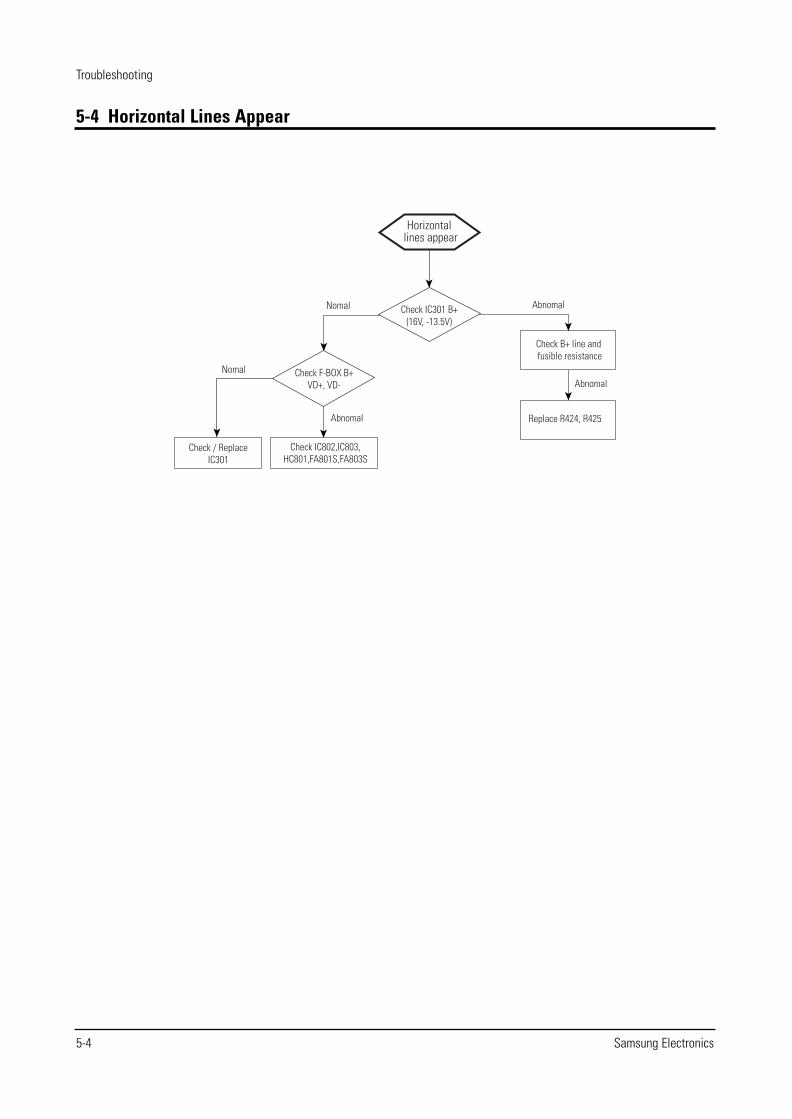
5-4 Horizontal Lines Appear
Troubleshooting
Horizontal lines appear
Nomal
Nomal
Abnomal
Abnomal
Abnomal
Check IC301 B+(16V, -13.5V)
Check F-BOX B+VD+, VD-
Check / ReplaceIC301
Check IC802,IC803,HC801,FA801S,FA803S
Replace R424, R425
Check B+ line and fusible resistance
TP02TP01
TP02
TP09
TP10
TP05
TP11
TP03
TP04
TP07TP08
TP06
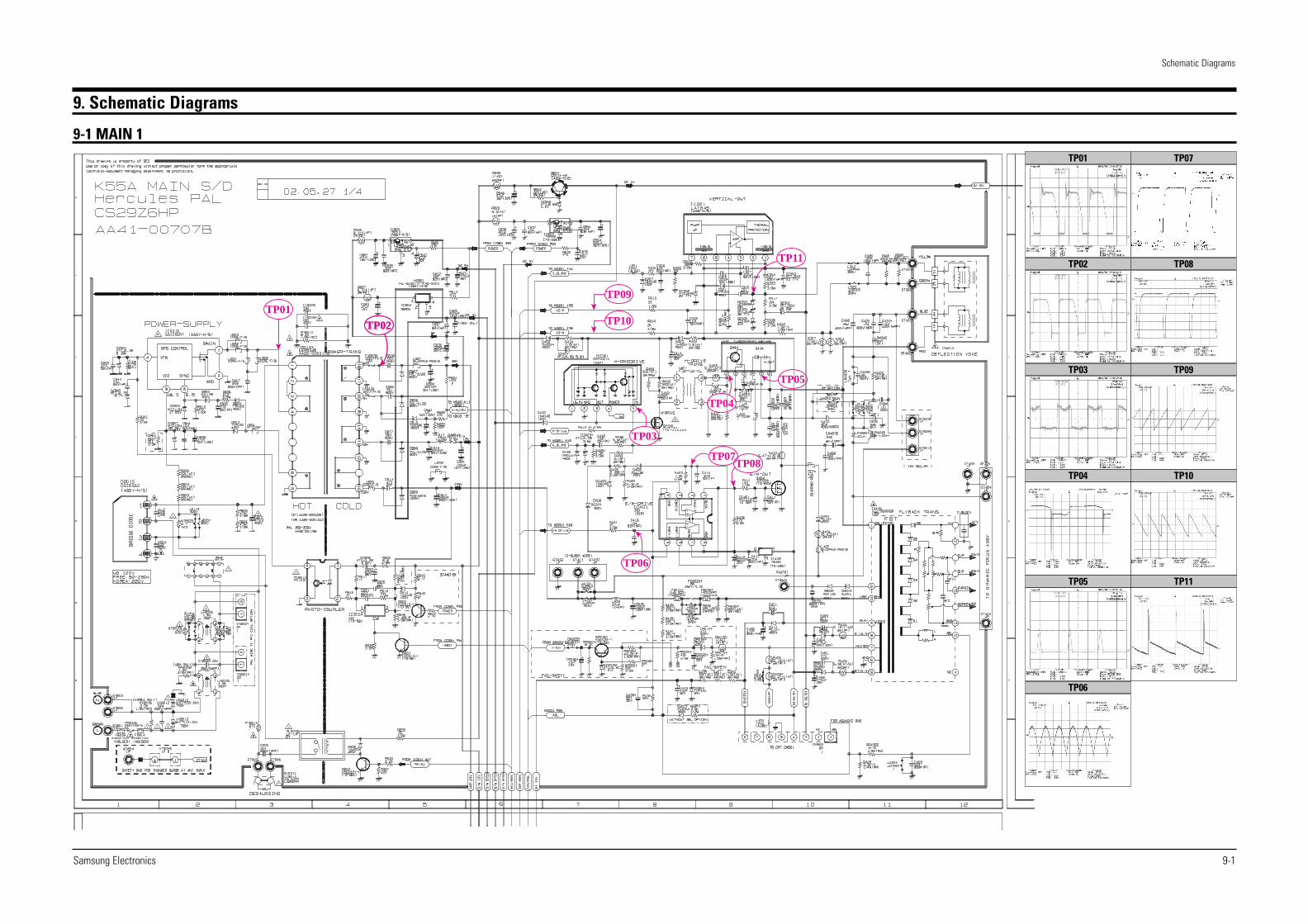
9. Schematic Diagrams
Samsung Electronics
Schematic Diagrams
9-1
9-1 MAIN 1TP07
TP08
TP09
TP10
TP11
TP01
TP02
TP03
TP04
TP05
TP06
Schematic Diagrams
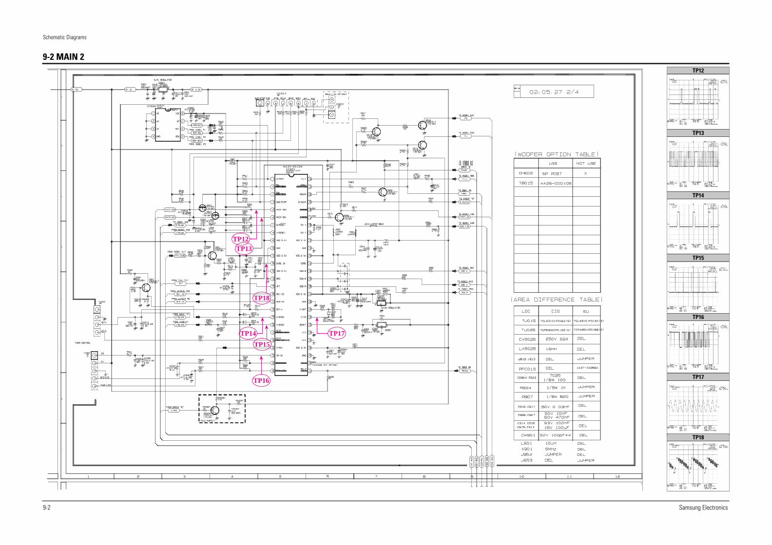
9-2 Samsung Electronics
TP12TP13
TP18
TP15
TP14
TP16
TP17
9-2 MAIN 2TP12
TP13
TP14
TP15
TP16
TP17
TP18
Samsung Electronics
Schematic Diagrams
9-3
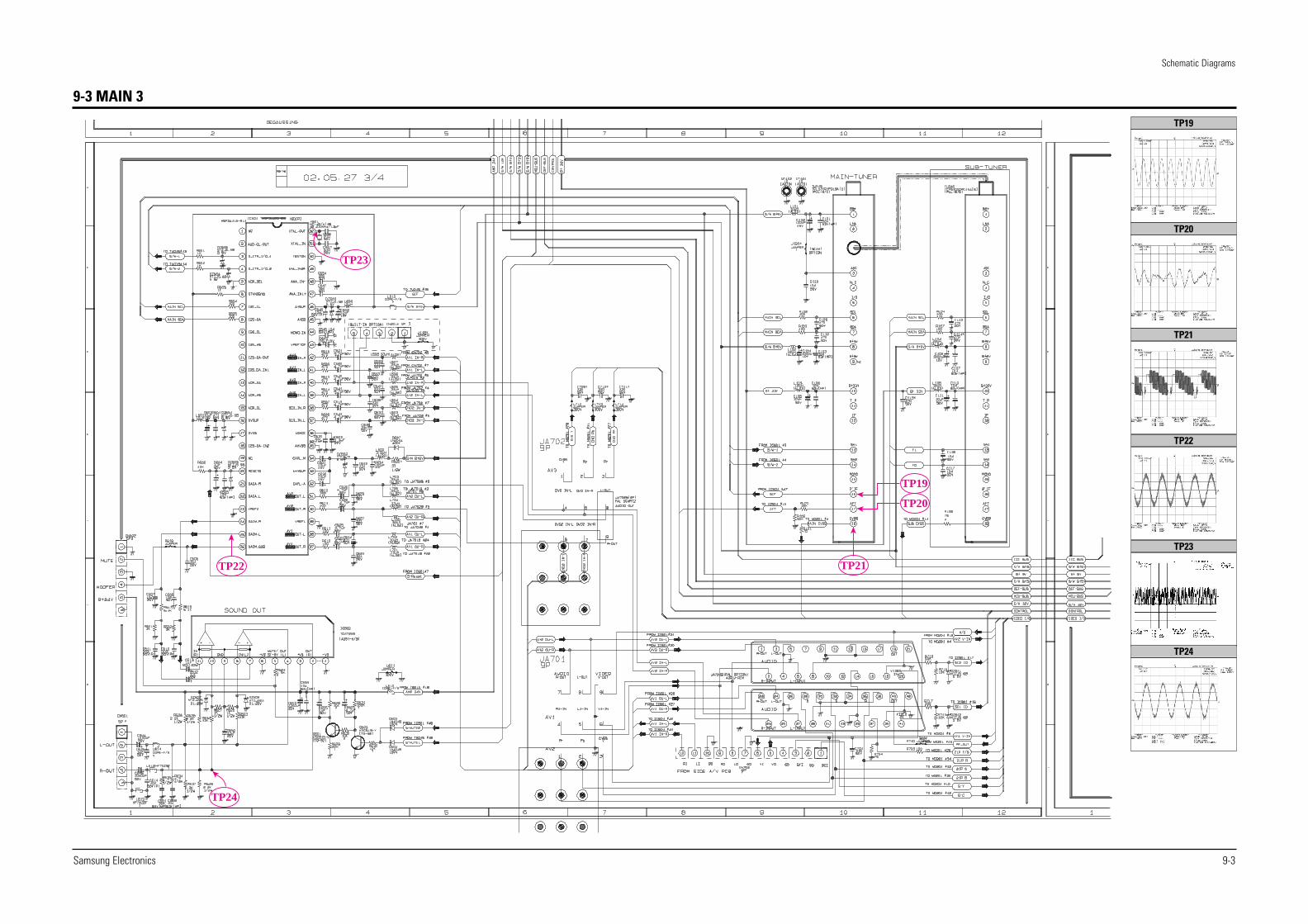
9-3 MAIN 3
TP19
TP20
TP21TP22
TP23
TP24
TP19
TP20
TP21
TP22
TP23
TP24
Schematic Diagrams
9-4 Samsung Electronics
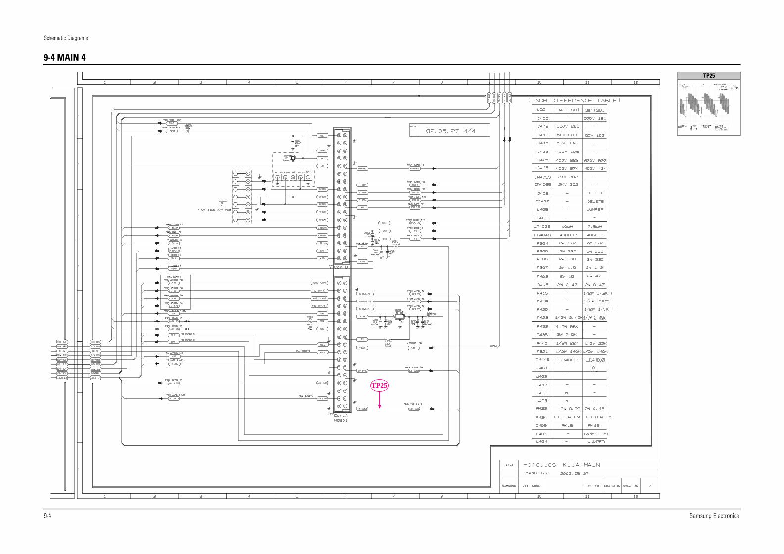
9-4 MAIN 4
TP25
TP25
Samsung Electronics
Schematic Diagrams
9-5
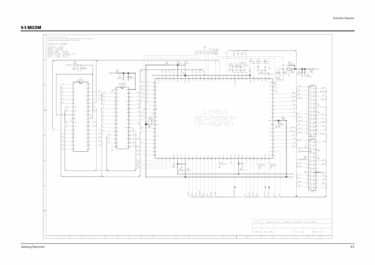
9-5 MICOM
Schematic Diagrams
9-6 Samsung Electronics
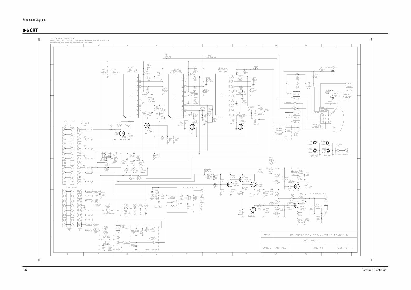
9-6 CRT
Samsung Electronics
Schematic Diagrams
9-7
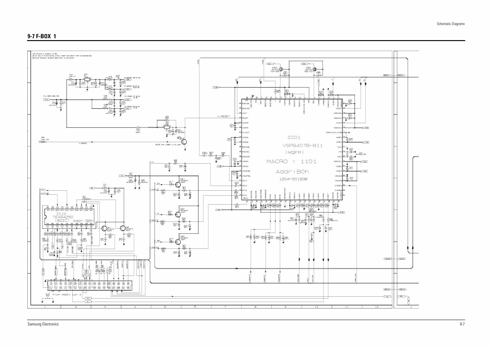
9-7 F-BOX 1
Schematic Diagrams
9-8 Samsung Electronics
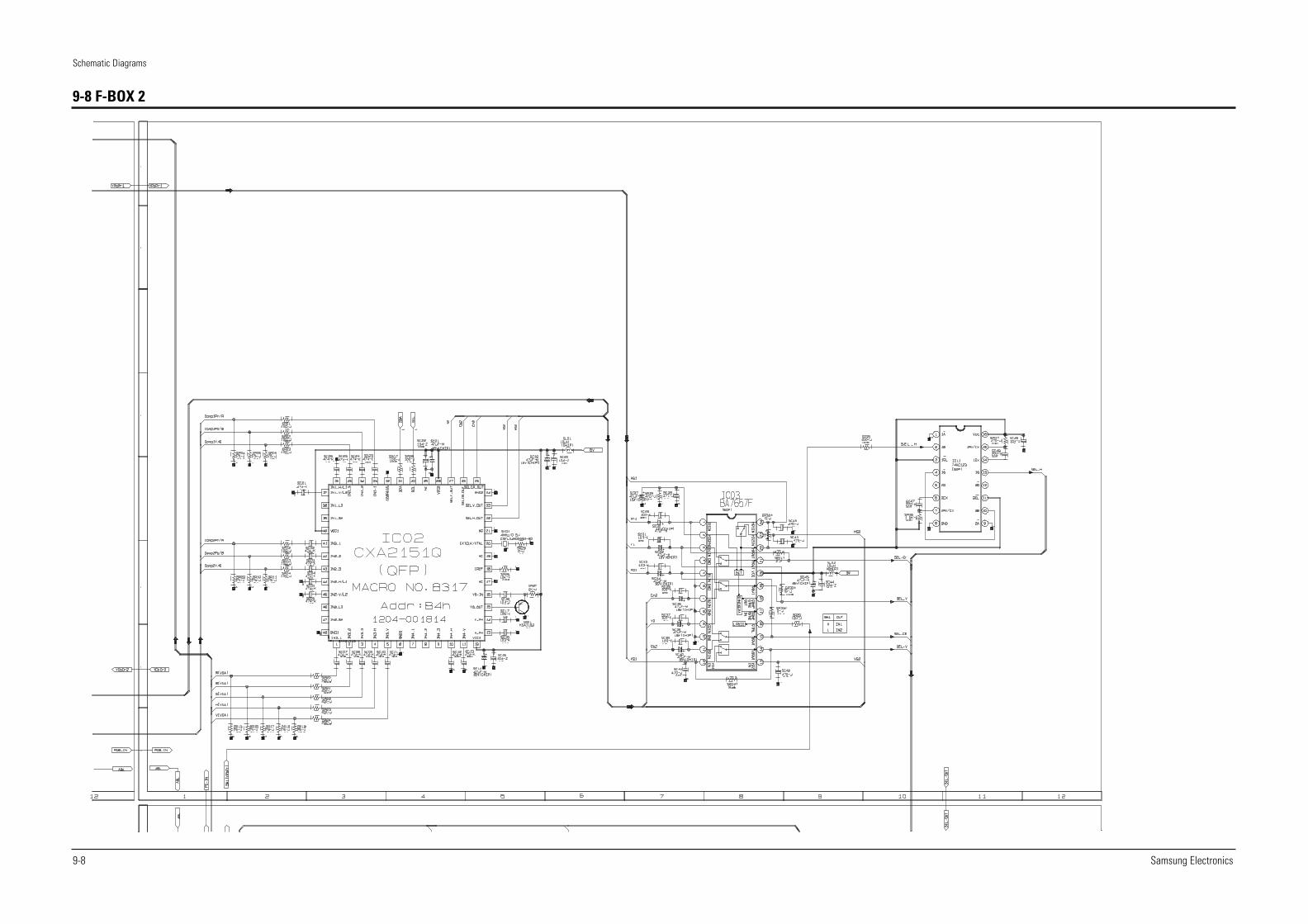
9-8 F-BOX 2
Samsung Electronics
Schematic Diagrams
9-9
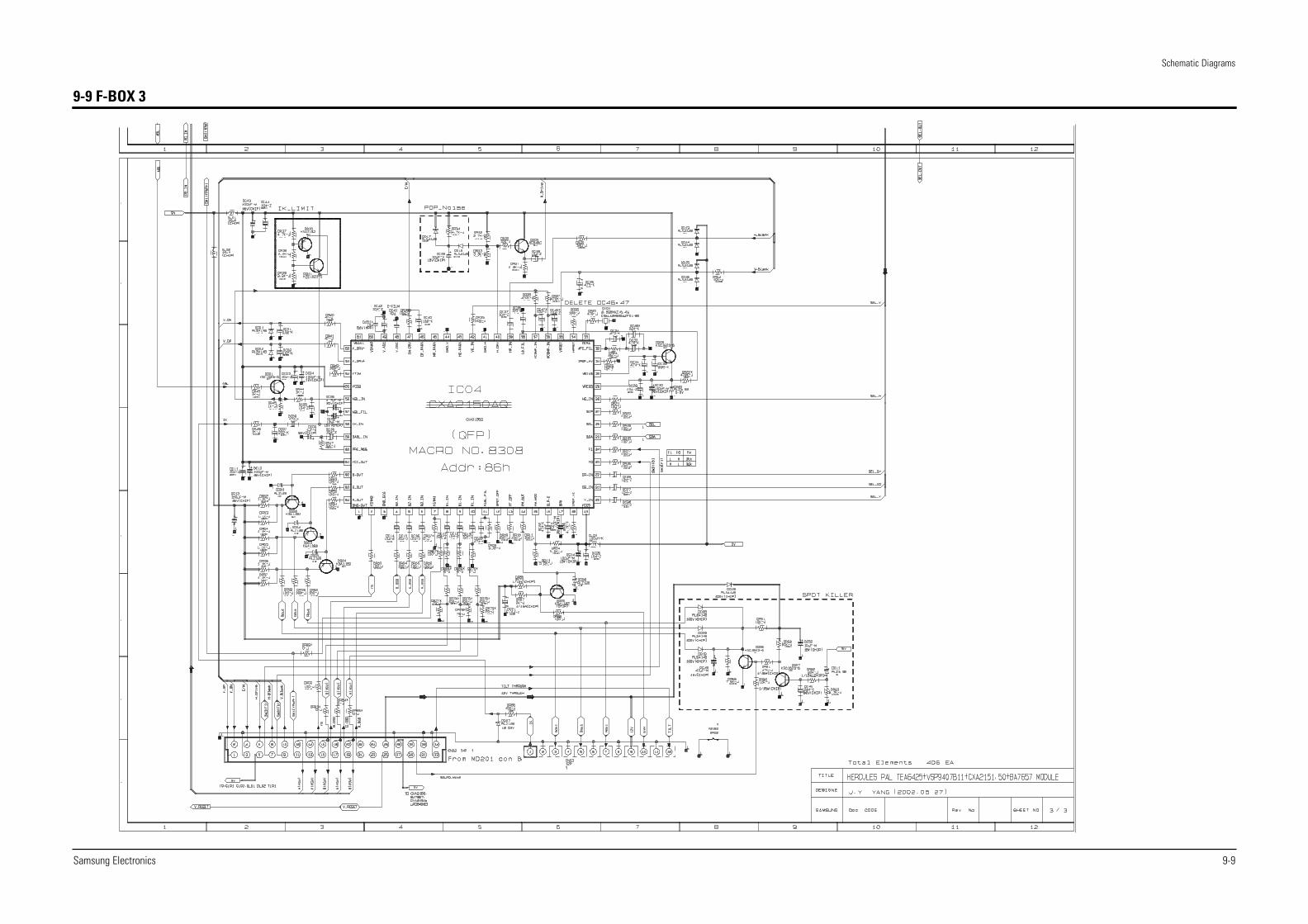
9-9 F-BOX 3
Schematic Diagrams
9-10 Samsung Electronics
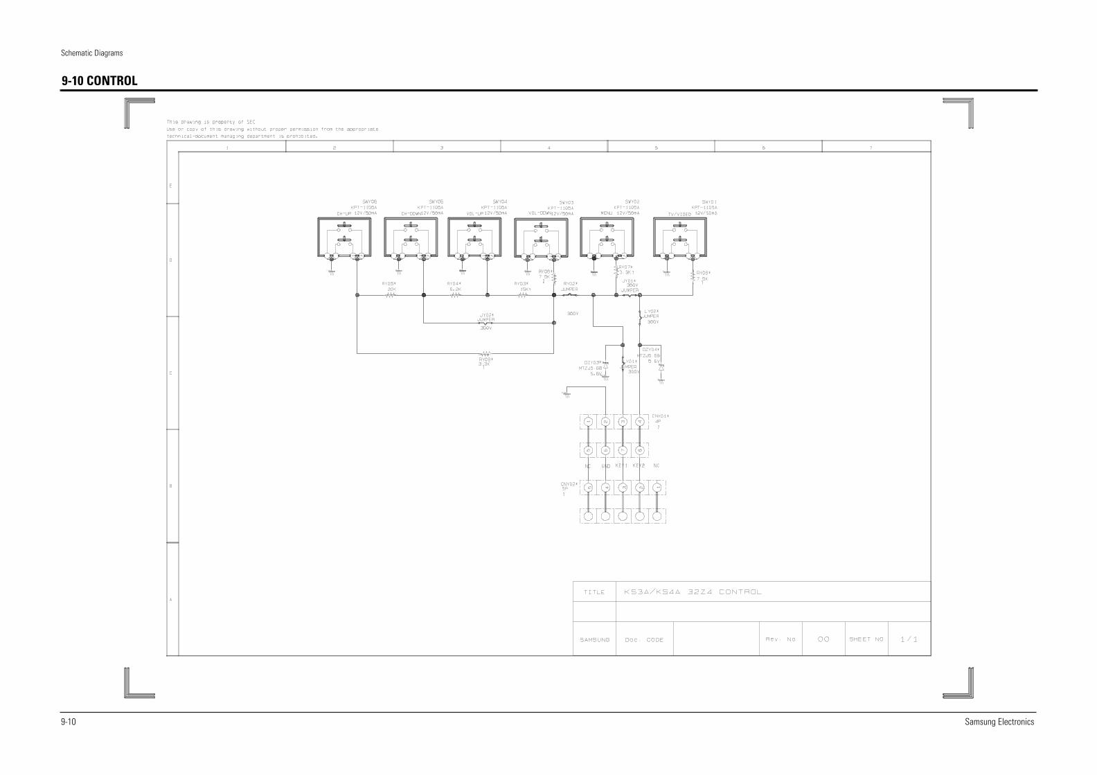
9-10 CONTROL
Samsung Electronics
Schematic Diagrams
9-11
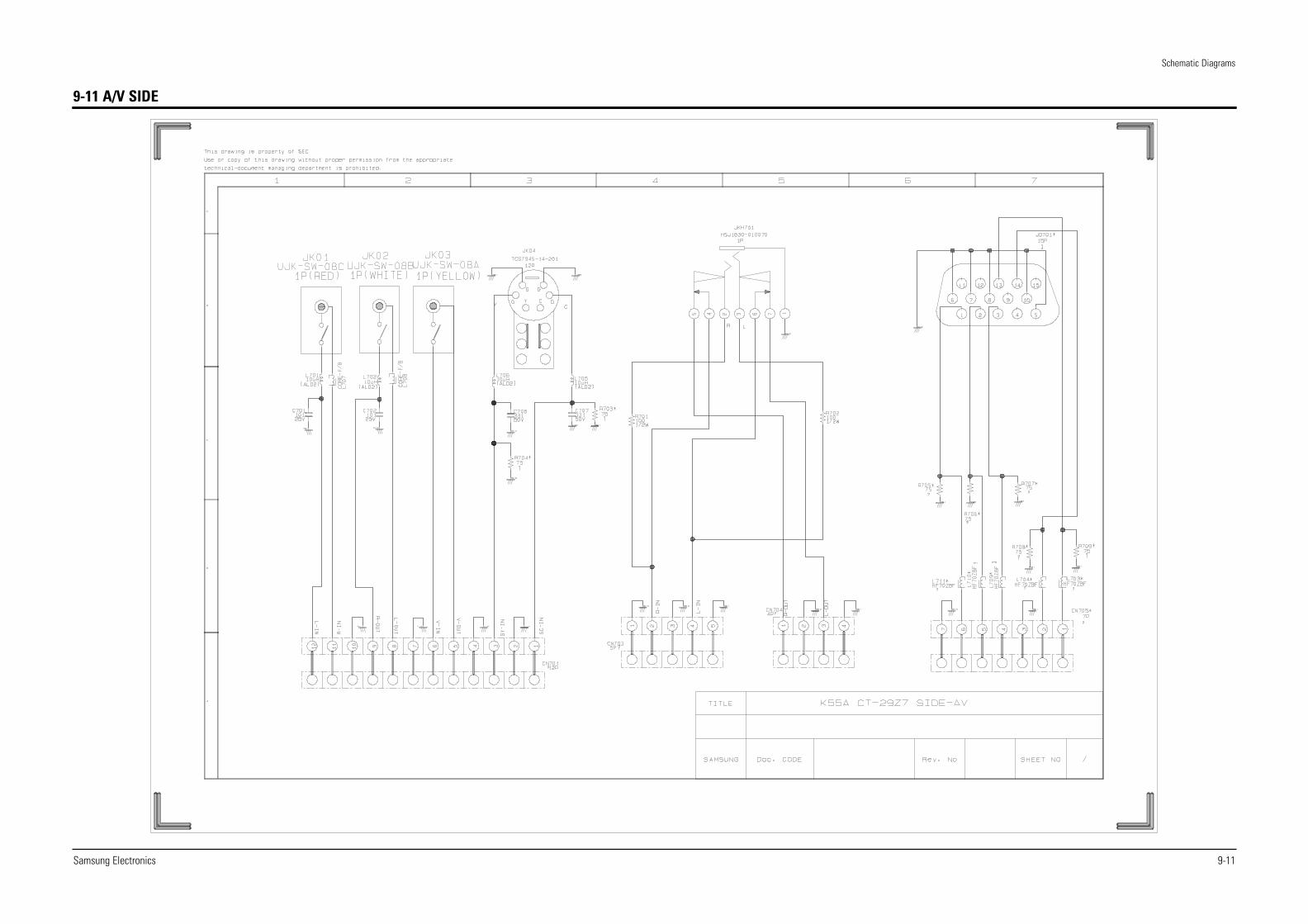
9-11 A/V SIDE
Schematic Diagrams
9-12 Samsung Electronics
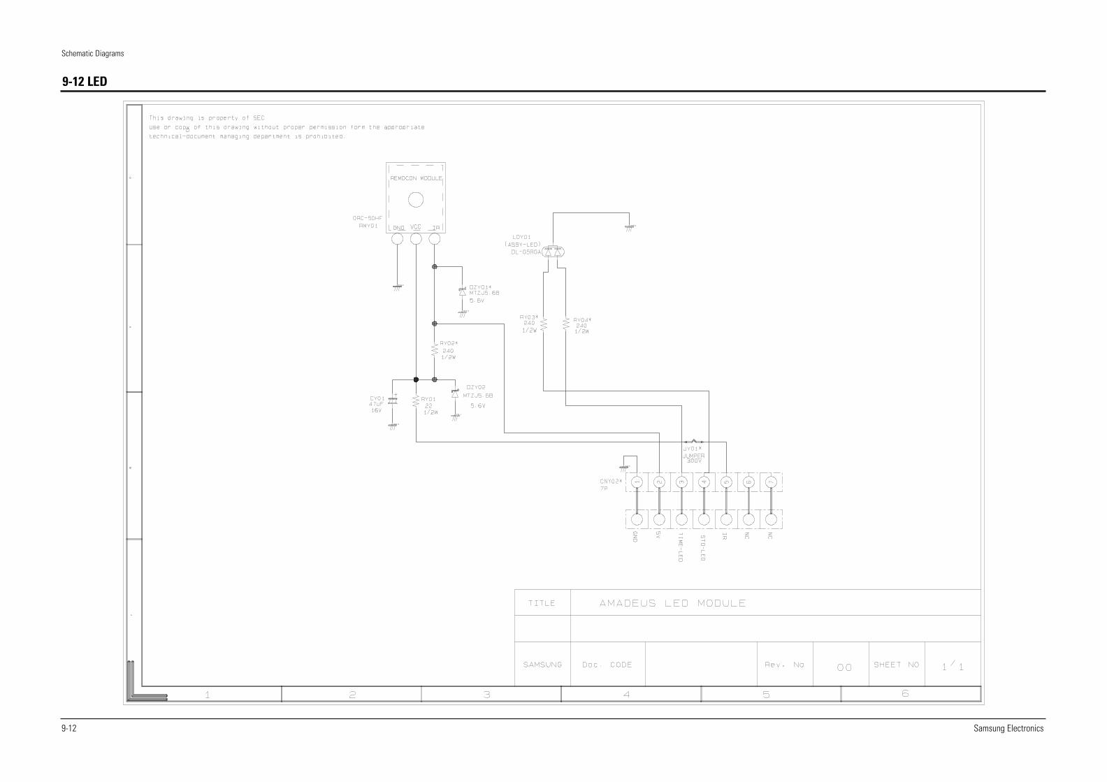
9-12 LED