collapse resistance of unreinforced steel moment connectionsshb.skku.edu/_res/hibs/etc/60.pdf ·...
TRANSCRIPT
Collapse resistance of unreinforced steel moment connections
Taejin Kim1, Un-Suk Kim1 and Jinkoo Kim2*,†
1 Chang-Minwoo Structural Consultants, Seoul, Korea2 Department of Architectural Engineering, Sungkyunkwan University, Suwon, Korea, 440–746
SUMMARY
Experimental and analytical studies of steel moment connections in gravity load resisting systems were conducted to understand the connection behaviour under progressive collapse. An exterior beam–column assemblage was selected from the gravity load resisting system in a steel building. Two identical, full-scale, unreinforced welded steel beam-to-column moment connection specimens were tested under monotonic and cyclic loading to investigate the effects of applied loading conditions on the connection rotation capac-ity. The beam web was connected to the column fl ange by bolting and the beam fl anges were complete joint penetration welded to the column fl ange. The specimens failed by fracture in the beam fl ange CJP weld at story drifts of 9.2 % (specimen SP1 under monotonic loading) and 3.4% (specimen SP2 under cyclic loading). The maximum drift angle achieved in the monotonic test exceeded the General Service Administration criterion for welded unreinforced fl ange connections, and the amount of dissipated energy of SP1 turned out to be smaller than that of SP2. The fi nite element analysis of the test specimen was also conducted to validate the test results, and the analysis results matched well with those obtained from experi-ments. Copyright © 2010 John Wiley & Sons, Ltd.
1. INTRODUCTION
The progressive collapse refers to the phenomenon that local damage of structural elements caused by abnormal loads results in global collapse of the structure. In the ‘Best practice for reducing the potential for progressive collapse in buildings’ published by the NIST (2007) the potential abnormal load hazards that can trigger progressive collapse are categorized as: aircraft impact, design/construc-tion error, fi re, gas explosions, accidental overload, hazardous materials, vehicular collision, bomb explosions, etc. As these hazards have low probability of occurrence, they are either not considered in structural design or addressed indirectly by passive protective measures. Most of them have char-acteristics of acting over a relatively short period of time and result in dynamic responses.
Steel moment connections are considered to have large ductility. The seismic performance of the steel connections has been verifi ed through full-size experiments: welded unreinforced fl ange-welded web (WUF-W) by Ricles et al. (2002), reduced beam section (RBS) by Jones et al. (2002), welded cover plated fl ange (WCPF) by Kim et al. (2002), for examples. In the United States the perimeter frames are often designed as moment frames resisting all lateral load and the internal frames are pin-connected to resist only gravity load. In this case the perimeter frames are expected to have some resistance to progressive collapse caused by sudden removal of a perimeter column. Sometimes when there exist shear walls or braces, the moment frames are designed to support only gravity load. In this case the strength of beam–column joints may not be enough to resist progressive collapse. Much research has been carried out regarding the progressive collapse resisting capacity of steel moment frames and connections. Kim and An (2009) investigated the effect of catenary action on the progres-sive collapse potential of steel structures. Kim and Kim (2009) investigated the reinforcing effect of the panel zone on the progressive collapse and capacity of moment resisting steel frames with the aid
* Correspondence to: Jinkoo Kim, Dept. of Architectural Eng., Sungkyunkwan University, Suwon, Republic of Korea, 440–746.
† E-mail: [email protected]
THE STRUCTURAL DESIGN OF TALL AND SPECIAL BUILDINGS
Copyright © 2010 John Wiley & Sons, Ltd.
Published online ber 2010 in Wiley Online Library (wileyonlinelibrary.com ). DOI: 10.1002/tal.6Struct. Design Tall Spec. Build. 21, – (2012)
36/journal/tal12 Novem724 735
Copyright © 2010 John Wiley & Sons, Ltd.
of nonlinear dynamic analysis. Astaneh-Asl et al. (2001) carried out ‘column-drop’ tests of a one story steel structure to explore the strength of a typical steel structure and fl oor system to resist progressive collapse in the event of removal of a column. The tests indicated that after removal of the middle perimeter column the fl oor is not expected to collapse due to catenary action of steel deck and girders. Khandelwal and El-Tawil (2007) carried out fi nite element analyses of beam–column subassemblages of a steel special moment resisting frame to investigate catenary action, and demonstrated the ductility of seismically designed special moment frame connections. Byfi eld and Paramasivam (2007) showed that industry standard beam–column connections possess insuffi cient ductility to accommodate the large fl oor displacements that occur during catenary action. Kim and Park (2008) proposed a plastic design method for steel moment frames to prevent progressive collapse.
Recently, the General Service Administration (GSA) presented a practical guideline for design to reduce collapse potential of federal buildings (GSA, 2003), and the Department of Defence (DoD) also presented a guideline for the new and existing DoD buildings (DoD, 2005). The failure criteria proposed in those guidelines are beam rotational capacities determined based on the test results of beam–column joints subjected to seismic load, and may not properly represent the behaviour of beam–column joints under progressive collapse. In this study two beam–column joints designed to resist only gravity load were constructed, and monotonic and cyclic loading tests were conducted to evaluate maximum rotational capacities for progressive collapse and earthquake excitation, respec-tively. By comparing the two test results the failure criteria for progressive collapse specifi ed in the guidelines for beam–column joints were evaluated and recommendation was made for future develop-ment of the criteria.
2. TEST OF EXTERIOR BEAM–COLUMN SUBASSEMBLAGES
2.1. Example building and test specimens
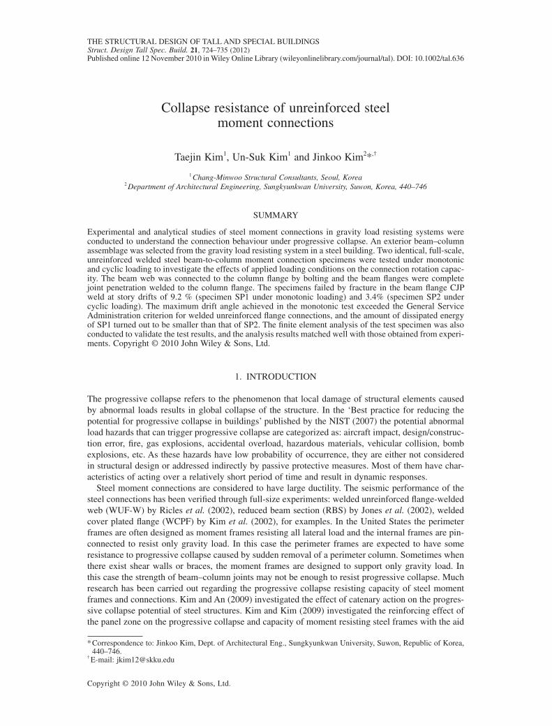
A three story steel building shown in Figure 1 was designed for a prototype connection model. Shear walls are designed to take all lateral loads such as wind and earthquake loads, whereas moment-
6,000 6,000 6,000 6,000 6,000
7,50
03,
000
7,50
0
30,000
18,0
00
3,200
3,200
3,600 1st FL.
2nd FL.
3rd FL.
Roof
1st FL.
2nd FL.
3rd FL.
(a)
(b)
Figure 1. Example building. (a) Plan. (b) Elevation.
Struct. Design Tall Spec. Build. 21, 724–735 (2012)DOI: 10.1002/tal
COLLAPSE RESISTANCE OF MOMENT CONNECTIONS 725
Copyright © 2010 John Wiley & Sons, Ltd.
resisting frames support only gravity loads. The beam–column connection prototype for the test is a single-sided, beam-to-column connection assemblage that is representative of the exterior beam-to-column connections as shown in Figure 1 with dotted lines. Two single-sided beam–column connec-tion assemblages were tested. To simplify the interpretation of the data H-400 × 200 × 8 × 13 and H-300 × 300 × 10 × 15 sections were used as beams and columns, respectively, in both tests.
The two test specimens were named as SP1 and SP2, respectively. The specimen SP1 was mono-tonically loaded to simulate the connection behaviour under progressive building collapse, while the specimen SP2 was cyclically loaded to simulate the seismic behaviour of the frame. The beam-to-column connection of the test specimen was a welded unreinforced fl ange-bolted web (WUF-B) moment connection. The column height of the test specimen was 1800 mm and the length of the beam from the column face to the centreline of the actuator was 2100 mm. Such dimensions were set due to the limitation of test equipments. From the preliminary analysis of the test specimen, it was found that differences in the dimensions do not affect the local response of the connection signifi cantly. Information on each test specimen is presented in Table 1.
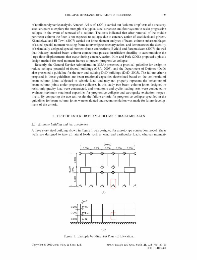
Figure 2 presents the connection details for the test specimen. The beam web was bolted to the shear tab of the column using 5-M24 high tension bolts. The beam fl anges were welded to the column
Table 1. Test specimen details.
Loading protocol
Specimen SP1 Specimen SP2
Monotonic Cyclic
Beam length 2100 mmBeam size H-400 × 200 × 8 × 13 (SS400)Shear tab thickness 16 mm (SS400)Column height 1800 mmColumn size H-300 × 300 × 10 × 15 (SS400)Continuity plate thickness (mm) 13 mm (SS400)Number of bolts in shear tab 5-M24 (F10T)
Figure 2. Connection details of the test specimens.
T. KIM, E.-S. KIM AND J. KIM726
Struct. Design Tall Spec. Build. 21, 724–735 (2012)DOI: 10.1002/tal
Copyright © 2010 John Wiley & Sons, Ltd.
fl ange using the complete joint penetration (CJP) welding in the shop. Both roots of the top and bottom beam CJP welds were directed to the centre line of the beam section. Backup bars were not removed after completion of CJP welding. Continuity plates with the same thickness with the beam fl ange were installed between the column fl anges to prevent local deformation of the column fl anges and web due to the beam fl ange forces.
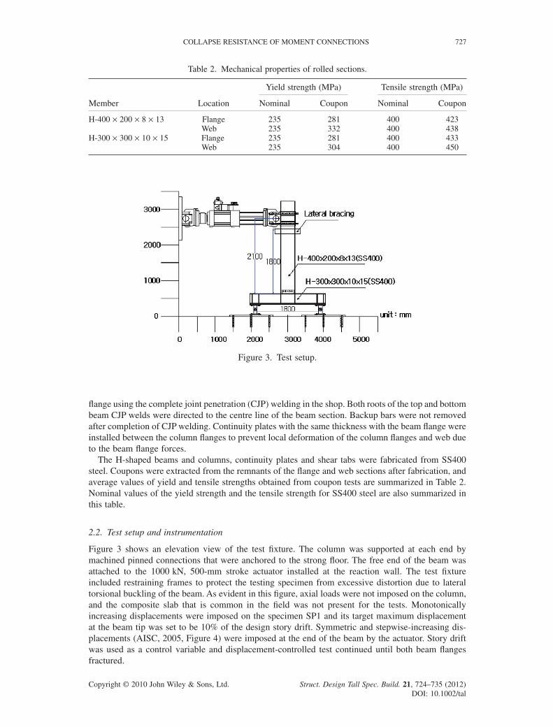
The H-shaped beams and columns, continuity plates and shear tabs were fabricated from SS400 steel. Coupons were extracted from the remnants of the fl ange and web sections after fabrication, and average values of yield and tensile strengths obtained from coupon tests are summarized in Table 2. Nominal values of the yield strength and the tensile strength for SS400 steel are also summarized in this table.
2.2. Test setup and instrumentation
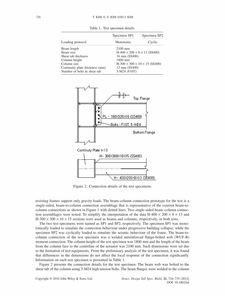
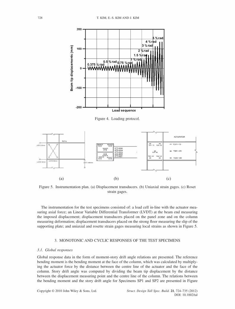
Figure 3 shows an elevation view of the test fi xture. The column was supported at each end by machined pinned connections that were anchored to the strong fl oor. The free end of the beam was attached to the 1000 kN, 500-mm stroke actuator installed at the reaction wall. The test fi xture included restraining frames to protect the testing specimen from excessive distortion due to lateral torsional buckling of the beam. As evident in this fi gure, axial loads were not imposed on the column, and the composite slab that is common in the fi eld was not present for the tests. Monotonically increasing displacements were imposed on the specimen SP1 and its target maximum displacement at the beam tip was set to be 10% of the design story drift. Symmetric and stepwise-increasing dis-placements (AISC, 2005, Figure 4) were imposed at the end of the beam by the actuator. Story drift was used as a control variable and displacement-controlled test continued until both beam fl anges fractured.
Figure 3. Test setup.
Table 2. Mechanical properties of rolled sections.
Member Location
Yield strength (MPa) Tensile strength (MPa)
Nominal Coupon Nominal Coupon
H-400 × 200 × 8 × 13 Flange 235 281 400 423Web 235 332 400 438
H-300 × 300 × 10 × 15 Flange 235 281 400 433Web 235 304 400 450
Struct. Design Tall Spec. Build. 21, 724–735 (2012)DOI: 10.1002/tal
COLLAPSE RESISTANCE OF MOMENT CONNECTIONS 727
Copyright © 2010 John Wiley & Sons, Ltd.
The instrumentation for the test specimens consisted of: a load cell in-line with the actuator mea-suring axial force; an Linear Variable Differential Transformer (LVDT) at the beam end measuring the imposed displacement; displacement transducers placed on the panel zone and on the column measuring deformation; displacement transducers placed on the strong fl oor measuring the slip of the supporting plate; and uniaxial and rosette strain gages measuring local strains as shown in Figure 5.
3. MONOTONIC AND CYCLIC RESPONSES OF THE TEST SPECIMENS
3.1. Global responses
Global response data in the form of moment-story drift angle relations are presented. The reference bending moment is the bending moment at the face of the column, which was calculated by multiply-ing the actuator force by the distance between the centre line of the actuator and the face of the column. Story drift angle was computed by dividing the beam tip displacement by the distance between the displacement measuring point and the centre line of the column. The relations between the bending moment and the story drift angle for Specimens SP1 and SP2 are presented in Figure
Figure 4. Loading protocol.
(a) (b) (c)
Figure 5. Instrumentation plan. (a) Displacement transducers. (b) Uniaxial strain gages. (c) Roset strain gages.
T. KIM, E.-S. KIM AND J. KIM728
Struct. Design Tall Spec. Build. 21, 724–735 (2012)DOI: 10.1002/tal
Copyright © 2010 John Wiley & Sons, Ltd.
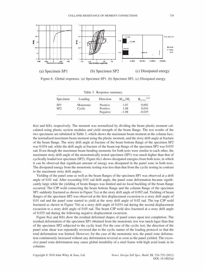
6(a) and 6(b), respectively. The moment was normalized by dividing the beam plastic moment cal-culated using plastic section modulus and yield strength of the beam fl ange. The test results of the two specimens are tabulated in Table 3, which shows the maximum beam moment at the column face, the normalized maximum beam moment using the plastic moment, and the story drift angle at fracture of the beam fl ange. The story drift angle at fracture of the beam bottom fl ange of the specimen SP2 was 0.034 rad, while the drift angle at fracture of the beam top fl ange of the specimen SP2 was 0.035 rad. Even though the maximum beam bending moments for both tests were similar to each other, the maximum story drift angle of the monotonically tested specimen (SP1) was much higher than that of cyclically loaded test specimen (SP2). Figure 6(c) shows dissipated energies from both tests, in which it can be observed that signifi cant amount of energy was dissipated in the panel zone in both tests. The dissipated energy from the monotonic testing was less than that from the cyclic testing in contrast to the maximum story drift angles.
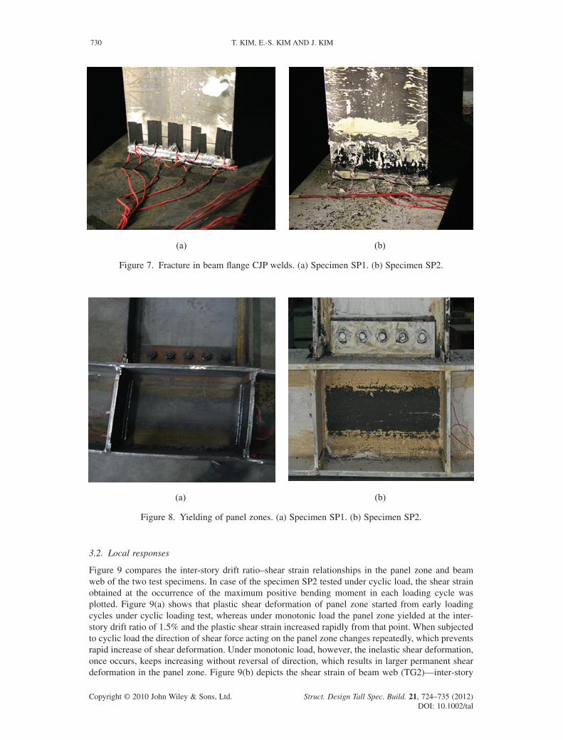
Yielding of the panel zone as well as the beam fl anges of the specimen SP1 was observed at a drift angle of 0.01 rad. After exceeding 0.01 rad drift angle, the panel zone deformation became signifi -cantly large while the yielding of beam fl anges was limited and no local buckling of the beam fl ange occurred. The CJP weld connecting the beam bottom fl ange and the column fl ange of the specimen SP1 suddenly fractured as shown in Figure 7(a) at the story drift angle of 0.092 rad. Yielding of beam fl anges of the specimen SP2 was observed at the fi rst displacement excursion to a story drift angle of 0.01 rad and the panel zone started to yield at the story drift angle of 0.02 rad. The top CJP weld fractured as shown in Figure 7(b) at a story drift angle of 0.034 rad during the second displacement excursion to a story drift angle of 0.05 rad. The beam CJP weld also fractured at a story drift angle of 0.035 rad during the following negative displacement excursion.
Figure 8(a) and 8(b) show the residual deformed shapes of panel zones upon test completion. The residual deformation of the specimen SP1 obtained from the monotonic test was much lager than that of the specimen SP2 subjected to the cyclic load. For the case of the cyclic test, the direction of the panel zone shear was repeatedly reversed due to the cyclic nature of the loading protocol so that the total deformation was limited. However, for the case of the monotonic test, the panel zone deforma-tion continuously increased without any deformation reversal as soon as the panel yielded. The exces-sive panel zone deformation may cause global instability of a steel frame with high axial loads in its columns.
(a) Specimen SP1 (b) Specimen SP2 (c) Dissipated energy
Figure 6. Global responses. (a) Specimen SP1. (b) Specimen SP2. (c) Dissipated energy.
Table 3. Response summary.
Specimen Loading Direction Mmax/Mp θfracture(rad)
SP1 Monotonic Positive 1.07 0.092SP2 Cyclic Positive 1.08 0.034
Negative −1.08 −0.035
Struct. Design Tall Spec. Build. 21, 724–735 (2012)DOI: 10.1002/tal
COLLAPSE RESISTANCE OF MOMENT CONNECTIONS 729
Copyright © 2010 John Wiley & Sons, Ltd.
3.2. Local responses
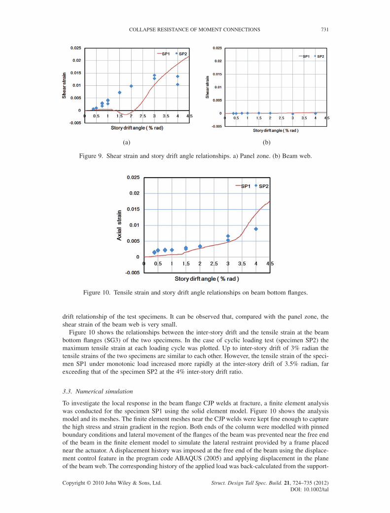
Figure 9 compares the inter-story drift ratio–shear strain relationships in the panel zone and beam web of the two test specimens. In case of the specimen SP2 tested under cyclic load, the shear strain obtained at the occurrence of the maximum positive bending moment in each loading cycle was plotted. Figure 9(a) shows that plastic shear deformation of panel zone started from early loading cycles under cyclic loading test, whereas under monotonic load the panel zone yielded at the inter-story drift ratio of 1.5% and the plastic shear strain increased rapidly from that point. When subjected to cyclic load the direction of shear force acting on the panel zone changes repeatedly, which prevents rapid increase of shear deformation. Under monotonic load, however, the inelastic shear deformation, once occurs, keeps increasing without reversal of direction, which results in larger permanent shear deformation in the panel zone. Figure 9(b) depicts the shear strain of beam web (TG2)—inter-story
(a) (b)
Figure 7. Fracture in beam fl ange CJP welds. (a) Specimen SP1. (b) Specimen SP2.
(a) (b)
Figure 8. Yielding of panel zones. (a) Specimen SP1. (b) Specimen SP2.
T. KIM, E.-S. KIM AND J. KIM730
Struct. Design Tall Spec. Build. 21, 724–735 (2012)DOI: 10.1002/tal
Copyright © 2010 John Wiley & Sons, Ltd.
drift relationship of the test specimens. It can be observed that, compared with the panel zone, the shear strain of the beam web is very small.
Figure 10 shows the relationships between the inter-story drift and the tensile strain at the beam bottom fl anges (SG3) of the two specimens. In the case of cyclic loading test (specimen SP2) the maximum tensile strain at each loading cycle was plotted. Up to inter-story drift of 3% radian the tensile strains of the two specimens are similar to each other. However, the tensile strain of the speci-men SP1 under monotonic load increased more rapidly at the inter-story drift of 3.5% radian, far exceeding that of the specimen SP2 at the 4% inter-story drift ratio.
3.3. Numerical simulation
To investigate the local response in the beam fl ange CJP welds at fracture, a fi nite element analysis was conducted for the specimen SP1 using the solid element model. Figure 10 shows the analysis model and its meshes. The fi nite element meshes near the CJP welds were kept fi ne enough to capture the high stress and strain gradient in the region. Both ends of the column were modelled with pinned boundary conditions and lateral movement of the fl anges of the beam was prevented near the free end of the beam in the fi nite element model to simulate the lateral restraint provided by a frame placed near the actuator. A displacement history was imposed at the free end of the beam using the displace-ment control feature in the program code ABAQUS (2005) and applying displacement in the plane of the beam web. The corresponding history of the applied load was back-calculated from the support-
(a) (b)
Figure 9. Shear strain and story drift angle relationships. a) Panel zone. (b) Beam web.
Figure 10. Tensile strain and story drift angle relationships on beam bottom fl anges.
Struct. Design Tall Spec. Build. 21, 724–735 (2012)DOI: 10.1002/tal
COLLAPSE RESISTANCE OF MOMENT CONNECTIONS 731

Copyright © 2010 John Wiley & Sons, Ltd.
reaction histories. Monotonic loading was applied and the maximum beam tip displacement corre-sponding to 0.1 radian of interstory drift angle was obtained.
Data from the coupon tests were used to establish stress-strain relationships for the beam and column fi nite elements. The fi rst mode shape of the analysis model obtained from an eigenvalue analysis was used as an initial imperfection to implement local buckling of the beam fl anges and the web. A typical Newton–Raphson numerical integration procedure can produce unbounded displace-ment increment when strength degradation of the model is initiated due to the local buckling. Thus, the modifi ed Risk algorithm (ABAQUS, 2005) was used to handle such instabilities. Figure 11 shows the fi nite element modeling of the test specimen.
The beam bending moment–story drift angle obtained from the fi nite element model of the speci-men SP1 is presented in Figure 12. The monotonic response of the test specimen is also shown for
Figure 11. Finite element model.
Figure 12. Comparison of global responses.
T. KIM, E.-S. KIM AND J. KIM732
Struct. Design Tall Spec. Build. 21, 724–735 (2012)DOI: 10.1002/tal

Copyright © 2010 John Wiley & Sons, Ltd.
comparison. It can be observed that the responses obtained from the numerical analysis and the experi-ment are almost identical, suggesting that the fi nite element model is quite accurate and that local responses from the analysis may be used to investigate the behaviour of the CJP weld.
4. EVALUATION OF RESPONSE DATA
4.1. CJP weld fracture
Figure 13 (a) shows tensile stress (σ22) distribution in the beam bottom fl ange near the CJP weld at the story drift angle of brittle weld fracture of the tested specimen. The tensile stresses along the CJP weld exceed the nominal yield strength (235 MPa) of the steel and approach to the ultimate strength (400 MPa). Figure 13 (b) shows the equivalent plastic strain (PEEQ in ABAQUS) distribution in the beam bottom fl ange near CJP weld at fracture. Even though the normal stress is greater than the yield strength, the yielding is limited in the small region. Thus, brittle fracture of the test specimen occurred because of high triaxial stress state in the CJP weld region that can induce microcrakcing and trigger rapid crack propagation.
4.2. Panel zone shear deformation
Both specimens failed due to factures in welded connections after undergoing signifi cant inelastic deformations. It was observed that large part of the inelastic deformation was contributed from panel zone deformation rather than from plastic hinge rotation. More specifi cally, kinking occurred in the fl ange CJP weld due to shear deformation of panel zone, which leaded to signifi cant localized bending stress and fi nally to fracture in the weld.
When the effect of panel zone deformation is not considered in the analysis for stability of a struc-ture, the shear strength of a panel zone can be estimated as follows in case the column axial load is less than 40% of the column strength (AISC, 2005):
R F d tv yw c w= 0 6. (1)
where Rv is the nominal shear strength of the column web, Fyw is the yield strength of the web, dc is the depth of the column member, tw is the web thickness of the column. According to the above equa-tion the panel zone shear strength of the test specimen is 423 kN. The shear force imposed on the exterior beam–column joint can be obtained from the following equation:
VM
d tVu
u
b fbc=
−− (2)
(a) (b)
Figure 13. Local responses on the beam fl anges at fracture. (a) Normal stress σ22 distribution. (b) PEEQ distribution.
Struct. Design Tall Spec. Build. 21, 724–735 (2012)DOI: 10.1002/tal
COLLAPSE RESISTANCE OF MOMENT CONNECTIONS 733
Copyright © 2010 John Wiley & Sons, Ltd.
where Mu is the bending moment at the end of the beam, db is the beam depth, tfb is the thickness of the beam fl ange and Vc is the shear force acting on the column. As the prototype structure is designed as a building frame system, in which shear walls resist all lateral loads and moment frames resist only gravity load, the bending moment imposed on the exterior beam–column joint is much less than that on the interior joints. Therefore panel zone reinforcement was not required on the test specimens which are exterior beam–column joints of a gravity-resisting system. However, to prevent progressive collapse the beam–column joints need to be designed to have strength higher than the beam plastic moment. For the test specimens the shear force acting on the panel zone is computed to be 624 kN. As this exceeds the panel zone strength of the test specimens, doubler plate is required in the panel zone when it is designed for progressive collapse or for seismic load.
4.3. Connection rotational capacity
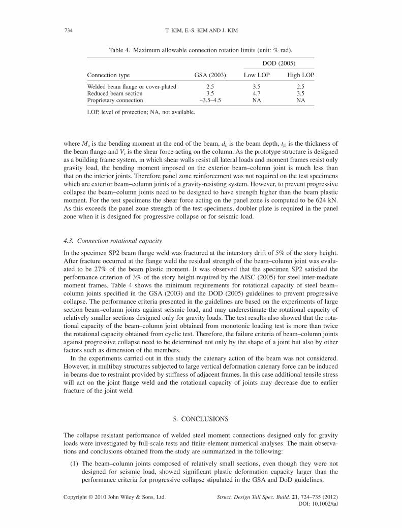
In the specimen SP2 beam fl ange weld was fractured at the interstory drift of 5% of the story height. After fracture occurred at the fl ange weld the residual strength of the beam–column joint was evalu-ated to be 27% of the beam plastic moment. It was observed that the specimen SP2 satisfi ed the performance criterion of 3% of the story height required by the AISC (2005) for steel inter-mediate moment frames. Table 4 shows the minimum requirements for rotational capacity of steel beam–column joints specifi ed in the GSA (2003) and the DOD (2005) guidelines to prevent progressive collapse. The performance criteria presented in the guidelines are based on the experiments of large section beam–column joints against seismic load, and may underestimate the rotational capacity of relatively smaller sections designed only for gravity loads. The test results also showed that the rota-tional capacity of the beam–column joint obtained from monotonic loading test is more than twice the rotational capacity obtained from cyclic test. Therefore, the failure criteria of beam–column joints against progressive collapse need to be determined not only by the shape of a joint but also by other factors such as dimension of the members.
In the experiments carried out in this study the catenary action of the beam was not considered. However, in multibay structures subjected to large vertical deformation catenary force can be induced in beams due to restraint provided by stiffness of adjacent frames. In this case additional tensile stress will act on the joint fl ange weld and the rotational capacity of joints may decrease due to earlier fracture of the joint weld.
5. CONCLUSIONS
The collapse resistant performance of welded steel moment connections designed only for gravity loads were investigated by full-scale tests and fi nite element numerical analyses. The main observa-tions and conclusions obtained from the study are summarized in the following:
(1) The beam–column joints composed of relatively small sections, even though they were not designed for seismic load, showed signifi cant plastic deformation capacity larger than the performance criteria for progressive collapse stipulated in the GSA and DoD guidelines.
Table 4. Maximum allowable connection rotation limits (unit: % rad).
Connection type GSA (2003)
DOD (2005)
Low LOP High LOP
Welded beam fl ange or cover-plated 2.5 3.5 2.5Reduced beam section 3.5 4.7 3.5Proprietary connection ∼3.5–4.5 NA NA
LOP, level of protection; NA, not available.
T. KIM, E.-S. KIM AND J. KIM734
Struct. Design Tall Spec. Build. 21, 724–735 (2012)DOI: 10.1002/tal
Copyright © 2010 John Wiley & Sons, Ltd.
(2) The two CJP joint specimens failed by the brittle fracture of beam fl ange weld due to: (a) stress concentration at CJP weld; (b) increase of yield stress under three-dimensional stress states; and (c) additional strain due to shear deformation of weak panel zone.
(3) The rotational capacity of the beam–column joint for monotonic loading turned out to be larger than that for cyclic loading.
(4) The energy dissipation capacity of the specimen subjected to cyclic load was larger than that of the specimen under monotonic load.
(5) The panel zone of a beam–column joint designed only for gravity load needs to be reinforced to prevent progressive collapse.
ACKNOWLEDGEMENT
This research was fi nancially supported by the Super-Tall Building R&D Project of the Korean Min-istry of Land, Transport, and Maritime Affairs (09CHUD-A053106–01–000000).
REFERENCES
ABAQUS. 2005. ABAQUS/Standard User’s Manual Version 6.5. ABAQUS, Inc.,: Pawtucket, RI.AISC. 2005. Seismic Provisions for Structural Steel Buildings. American Institute of Steel Construction: Chicago, IL.Astaneh-Asl A, Jones B, Zhao Y, Hwa R. 2001. Floor catenary action to prevent progressive collapse of steel structures. Report
number: UCB/CEE-STEEL-01/03, UC. Berkeley, CA.Byfi eld MP, Paramasivam S. 2007. Catenary action in steel-framed buildings. Structures and Buildings 160(5): 247–257DoD. 2005. Design of Buildings to Resist Progressive Collapse. Unifi ed Facilities Criteria (UFC), US Department of Defense:
Washington, D.C.GSA. 2003. Progressive Collapse Analysis and Design Guidelines for New Federal Offi ce Buildings and Major Modernization
Projects. US General Service Administration: Washington, D.C.Jones SL, Fry GT, Engelhardt MD. 2002. Experimental evaluation of cyclically loaded reduced beam section moment connec-
tions. Journal of Structural Engineering 128(4): 441–451.Khandelwal K, El-Tawil S. 2007. Collapse behavior of steel special moment resisting frame connections, Journal of Structural
Engineering ASCE 133(5): 646–655.Kim J, An D. 2009. Evaluation of progressive collapse potential of steel moment frames considering catenary action. The
Structural Design of Tall and Special Buildings 18(4): 455–465.Kim J, Kim T. 2009. Assessment of progressive collapse-resisting capacity of steel moment frames. Journal of Constructional
Steel Research 61(1): 169–179Kim J, Park J. 2008. Design of steel moment frames considering progressive collapase, Steel and Composite Structures 8(1):
85–98.Kim T, Whittaker AS, Gilani ASJ, Bertero VV, Takhirov SM. 2002. Experimental evaluation of plate-reinforced steel moment-
resisting connections. Journal of Structural Engineering 128(4): 483–491.NIST. 2007. Best Practices for Reducing the Potential for Progressive Collapse in Buildings. Report No. NISTIR 7396,
National Institute of Standards and Technology, Gaithersburg, MD, USA.Ricles JM, Mao C, Lu LW, Fisher JW. 2002. Inelastic cyclic testing of welded unreinforced moment connections. Journal of
Structural Engineering 128(4): 429–440.
Struct. Design Tall Spec. Build. 21, 724–735 (2012)DOI: 10.1002/tal
COLLAPSE RESISTANCE OF MOMENT CONNECTIONS 735