collapse and reconstruction of the crandic cedar river bridge … · collapse and reconstruction of...
TRANSCRIPT

Collapse and Reconstruction of the CRANDIC Cedar River Bridge
Chad Lambi, PE
Cedar Rapids and Iowa City Railway
Alliant Energy Transportation
2330 12th Street SW
Cedar Rapids, IA 52404
Jeffrey W. Teig, PE
HDR Engineering, Inc.
8404 Indian Hills Drive
Omaha, NE 68114
Word count: 6,221

Table of Contents ABSTRACT................................................................................................................................................INTRODUCTION ......................................................................................................................................THE GREAT FLOOD ................................................................................................................................RESTORING THE CEDAR RIVER BRIDGE CROSSING .....................................................................PLANNING THE CONSTRUCTION........................................................................................................EXISTING BRIDGE ..................................................................................................................................NEW CONSTRUCTION............................................................................................................................ADDITIONAL SCHEDULE SAVING TECHNIQUES............................................................................DESIGN AND BID PACKAGES ..............................................................................................................
Substructure Design and Bid Package ....................................................................................................Precast Concrete Fabrication and Delivery.............................................................................................Superstructure Erection Bid Package......................................................................................................
FINAL BRIDGE CONFIGURATION .......................................................................................................BRIDGE CONSTRUCTION......................................................................................................................TRACK CONSTRUCTION .......................................................................................................................

ABSTRACT
The Cedar Rapids and Iowa City Railway (The CRANDIC) suffered significant destruction from the 500-
year flood levels experienced in 2008 that plagued much of eastern Iowa. In addition to having several
miles of mainline railroad washed out, at 9:43 am on June 12, 2008 the CRANDIC also lost an 800-foot
long railroad bridge over the Cedar River in downtown Cedar Rapids, Iowa.
The CRANDIC connects with 4 railroads throughout eastern Iowa including Union Pacific, Iowa
Interstate, Canadian National, and the Iowa Northern. With the loss of the Cedar River bridge,
interchange with the CN and Iowa Northern was severed. With limited detour options available, it was
quickly determined to restore the bridge as soon as possible.
Soon after the flood, the CRANDIC immediately began removal of the destroyed structure. In the
meantime, the CRANDIC also hired HDR Engineering, Inc. (HDR) to commence design of a new
structure. Due to the urgent nature of the project and the limited time available for planning, there were
many challenges to complete the project as quickly as possible.
Soon after design was commenced, HDR quickly developed sufficient detail to allow the CRANDIC and
HDR to work with fabricators to begin fabricating the steel superstructure in September 2008.
Meanwhile, permit applications were pushed forward as quickly as possible. The project was then bid for
construction in December 2008 and construction was able to begin in January 2009. By June 2009 the
bridge was nearly complete and was in service July 6, 2009. Total cost of the bridge was approximately
$7.9M.
INTRODUCTION
The Cedar Rapids and Iowa City Railway (CRANDIC) suffered significant damage from the 2008
flooding that occurred over much of the Midwest. In addition to having several miles of mainline railroad
washed out, on June 12, 2008 the CRANDIC also lost their 800-foot bridge over the Cedar River in Cedar
Rapids, Iowa.
The CRANDIC connects with 4 railroads throughout eastern Iowa including Union Pacific, Iowa
Interstate, Canadian National, and the Iowa Northern. With the loss of the Cedar River Bridge,
interchange with the Canadian National and Iowa Northern was severed. With limited detour options
available, it was quickly determined to restore the bridge as soon as possible.
Soon after the flood, the CRANDIC immediately began removal of the collapsed structure. In the
meantime, the CRANDIC also hired HDR Engineering, Inc. (HDR) to commence design of a new
structure. Due to the urgent nature of the project and the limited time available for planning, many
challenges were overcome to complete the project as quickly as possible.
The purpose of this paper is to describe the challenges, design solutions and methods employed to
overcome the challenges to restore the Cedar River Bridge. The outcome was a restored, durable bridge
completed in a short period of time at a reasonable cost.
THE GREAT FLOOD
The existing bridge over the Cedar River consisted of the following:
• 50-foot west approach consisting of two steel beam spans
• 640-foot main bridge segment consisting of four through truss spans each 158.5 feet in length
• 111-foot east approach consisting of a 36-foot beam span and a 75-foot deck plate girder span
• All the spans had an open timber deck
The flooding that occurred in Cedar Rapids in June, 2008, was greater than the 500 year flooding event.
The CRANDIC personnel were paying particular attention to the rising water of the Cedar River and
knew their bridge crossing the river could be in jeopardy.
On June 10, 2008 the initial flood forecast called for the river to rise to a level of 22-ft, which would bring
the water up to the middle of the stringers on the truss spans. Given the rapid currents in the area of the
bridge and the design of the expansion joints on the bridge there was significant concern the steel trusses
could be swept from the piers. Therefore, loaded ballast cars were parked on the bridge to increase the
resistance between the piers, bearings, and steel trusses to overcome the forces of the water sweeping
against the bridge.
However, the flood waters did not adhere to the forecast and continued to rise. Late in the day on June
11, the forecast was revised for the river to reach a level of 24.5-ft, which would be near the top of rail
elevation on the bridge. At this level the work of the ballast cars would be critical to success or failure.
However, by early morning on June 12, the river had surpassed 24.5-ft and was approaching a level of 26-
ft. At this level the piers (originally constructed on spread footings) on the bridge began to succumb to
scour and started to sink. Then at 9:43 am on the morning of June 12 three of the truss spans collapsed
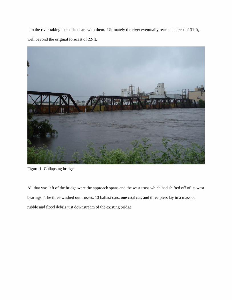
into the river taking the ballast cars with them. Ultimately the river eventually reached a crest of 31-ft,
well beyond the original forecast of 22-ft.
Figure 1- Collapsing bridge
All that was left of the bridge were the approach spans and the west truss which had shifted off of its west
bearings. The three washed out trusses, 13 ballast cars, one coal car, and three piers lay in a mass of
rubble and flood debris just downstream of the existing bridge.
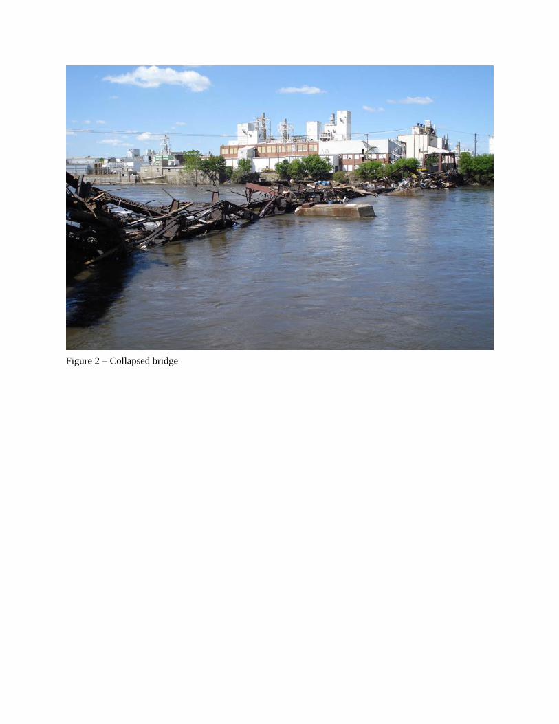
Figure 2 – Collapsed bridge

RESTORING THE CEDAR RIVER BRIDGE CROSSING
The CRANDIC contracted with Newt Marine of Dubuque, Iowa to remove the existing spans and piers
that were washed out during the flood. The contractor constructed a causeway out into the river to
facilitate removal of the washed out span and piers. A United States Army Corp of Engineers (USACE)
404 permit was required to construct the causeway, and the CRANDIC applied for and received a permit
from the USACE to construct the causeway. Construction of the causeway and the removal of the spans
and piers began on July 18, 2008 – as soon as possible after the flood waters receded.
Of interest during removal of the bridge was trying to salvage the ballast cars that had fallen in the river
and to place cars with minimal damage back into service. Due to the contractor’s careful work in
removing the bridge and rail cars, they were able to successfully remove each car intact, and within a few
months CRANDIC mechanical personnel were able to repair every ballast car for return to service.
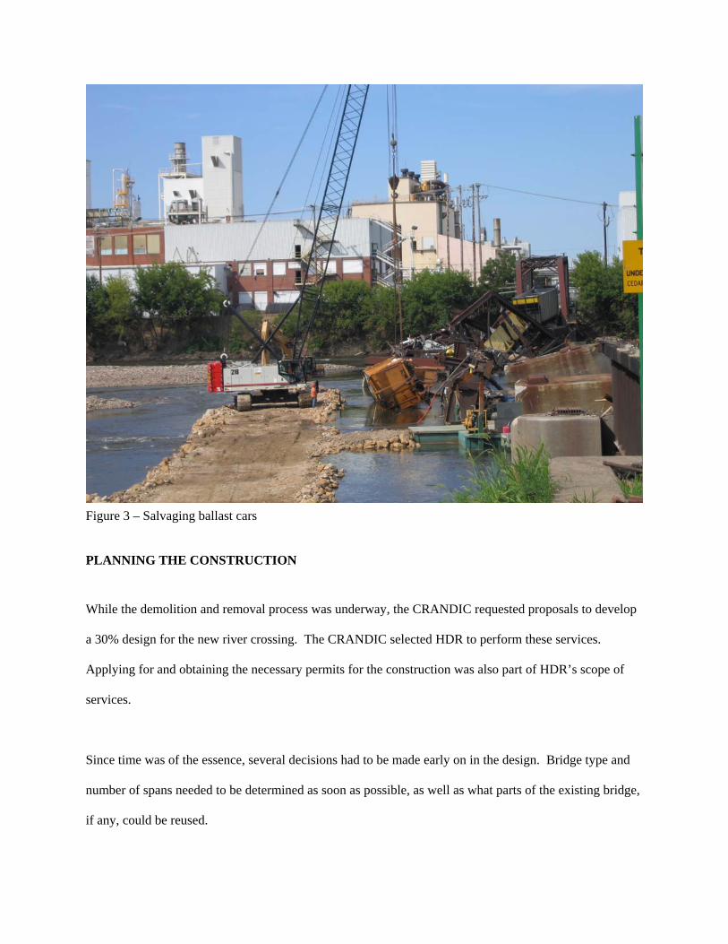
Figure 3 – Salvaging ballast cars
PLANNING THE CONSTRUCTION
While the demolition and removal process was underway, the CRANDIC requested proposals to develop
a 30% design for the new river crossing. The CRANDIC selected HDR to perform these services.
Applying for and obtaining the necessary permits for the construction was also part of HDR’s scope of
services.
Since time was of the essence, several decisions had to be made early on in the design. Bridge type and
number of spans needed to be determined as soon as possible, as well as what parts of the existing bridge,
if any, could be reused.

EXISTING BRIDGE
Due to the condition of what remained of the existing superstructure, it was determined that the only
portion of the bridge that could be reused was the east approach spans. The abutments and piers that
supported the east and west approach spans were the only substructures that could be reused. Of note, the
2 east piers and east abutment had been rebuilt by the Milwaukee Road around 1950. When reconstructed
they had been rebuilt with timber piling unlike the older piers that failed, which were on spread footings
and subsequently failed when scour occurred. The east approach spans were rated and found to be
sufficient for conversion to ballast deck spans using pre-cast concrete deck panels. The existing
substructures would require modifications to the elevation of the bearing surfaces in order to support the
new superstructure in coordination with the elevations of the existing superstructure.
NEW CONSTRUCTION
HDR’s scope included performing a Bridge Type Selection Analysis to determine the best type of
replacement structure for the new portion of the bridge considering cost, schedule and maintenance.
Several railroads were contacted to determine if existing spans were available to use for the new
construction. No existing spans were found. It therefore became necessary to fabricate new spans.
Three span types were evaluated for use in reconstruction of the Cedar River Bridge. These included
steel truss, through plate girder, and steel beam spans. Estimated cost of the three alternatives were as
follows:
Type Estimated Superstructure Cost
Steel Beam Spans – Rolled $ 5,649,000
Steel Through Plate Girder Spans $ 8,594,000
Steel Through Truss Spans $14,766,000
When considering cost and the speed of fabrication, the Steel Beam Span option was selected.
The Union Pacific Railroad (UPRR) granted permission to the CRANDIC to use their Long Span Steel
Beam Standards for the new spans. These standards use W36 and W40 wide flange steel shapes for the
main supporting longitudinal girders.
HDR considered through truss spans similar to the existing span lengths, long span through plate girders
and the UPRR standard beam spans. All of the superstructure types were to be supported on drilled shafts
with concrete caps.
While performing the type selection report, it was discovered that the W40 steel sections needed for the
steel beam concept were to be rolled in September of 2008 and not again until April of 2009. An order
for the material being rolled in September 2008 could not be made in time.
Steel fabricators were contacted and it was determined that there was a possibility that sufficient rolled
material for the new steel beam spans could be purchased from warehouses.
Therefore, to move things along quickly HDR utilized a unique approach to design and bid the
superstructure. HDR and the CRANDIC worked with fabricators to get the best price and schedule for
whatever material could used for the steel beam spans.
The new portion of the bridge was to have ten spans equaling a total of 631 feet. The average span length
of 63 feet was within the limits of the UPRR Steel Beam Span Standards. The UPRR Steel Beam Span
Standards used W40x431 steel beams for this span length. In order to incorporate as much flexibility as
possible into the beam sizes that could be used for the new superstructure, HDR developed designs for

varying span lengths using multiple beam sizes including W40 and W44 beams. All the designs were
based on the UPRR Steel Beam Span Standards allowing the fabricators to pick the beam sizes that were
available. The following beam sizes and span and corresponding maximum span lengths were developed:
Beam Size Maximum Span Length
W44x335 70 feet
W44x290 69 feet
W44x262 67 feet
W44x230 64 feet
W40x431 75 feet
W40x362 67 feet
W40x277 61 feet
Fabricators were asked to bid on ten spans equaling 631 feet utilizing any combination of the beam sizes
and span lengths. They were asked to develop shop drawings for review and approval as well.
Wyatt Industries won the superstructure fabrication bid and delivery. They had a bid of $3,474,334 and
could begin fabrication in November 2009 which was best in both categories. They proposed using W44
beams with the following span arrangement:
1 x W44x230 60 feet
1 x W44x230 61 feet
1 x W44x262 60 feet
3 x W44x262 65 feet
1 x W44x290 60 feet
1 x W44x290 65 feet
1 x W44x290 70 feet
1 x W44x335 60 feet
ADDITIONAL SCHEDULE SAVING TECHNIQUES
In addition to beginning steel fabrication early in the design process, several other techniques were used
to help expedite the permitting and construction of the new portion of the bridge:
• Soil borings for the new substructure design were taken from the causeway being used to remove
the collapsed bridge spans and piers.
• New piers could not be any wider than the existing piers that were washed out to facilitate the no-
rise condition for the 100 year flood water surface elevation required in the hydrologic and
hydraulic analyses (H&H).
• Low chord of the new superstructure could not be any lower than the low chord of the destroyed
spans.
• Requested an out of order review of the floodplain permit application by the Iowa Department of
Natural Resources.
• USACE was petitioned for permission to use the same causeway for construction that was used
for removal.
• Use of drilled shafts extending above the water surface rather than piles and pile caps which
would have required cofferdam construction and curing of cast-in-place concrete.
DESIGN AND BID PACKAGES
In addition to the Steel Fabrication Bid Package, three other major bid packages were developed for the
bridge construction. In total, the bid packages developed included:
1. Superstructure Fabrication and Delivery
2. Substructure Construction
3. Precast Concrete Fabrication and Delivery
4. Superstructure Erection
A bid package was not developed for track work, as track was constructed by CRANDIC personnel.
Substructure Design and Bid Package HDR designed and developed the substructure bid package concurrent with the development of the
superstructure design and bid package. The CRANDIC wanted to incorporate some aesthetic features
into the bridge design. However aesthetics was secondary to the getting the bridge constructed and in
service. To accommodate the future installation of possible aesthetic treatment, HDR incorporated large
embedded plates into extended pier caps.
The foundations for the substructures consisted of 36 inch diameter drilled shafts to bedrock with 24 inch
diameter rock sockets into the bedrock. The overlying soils consisted of clean sands and gravels.
Permanent steel casings were required to enable drilled shaft and column construction. The pier caps
were designed using cast-in-place reinforced concrete.
Dondlinger & Sons Construction Co., Inc. out of Wichita, KS was the successful bidder.
Precast Concrete Fabrication and Delivery
The precast concrete fabrication package included precast concrete ballast pans for the existing west
approach spans and the precast/prestressed concrete double box girder spans for the east approach spans.
This package also included the precast concrete riser blocks to raise the seats to the required elevation for
the new spans at the existing east abutment and piers. Coreslab Structures out of LaPlatte, NE won the
precast concrete fabrication.
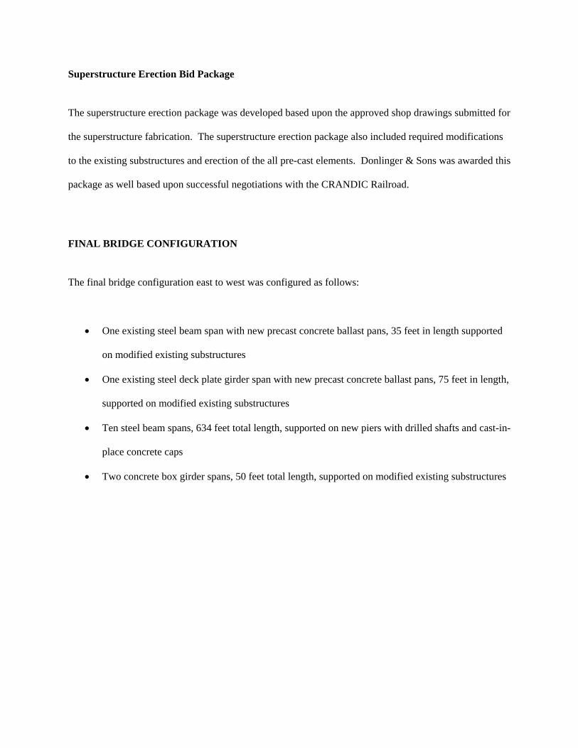
Superstructure Erection Bid Package
The superstructure erection package was developed based upon the approved shop drawings submitted for
the superstructure fabrication. The superstructure erection package also included required modifications
to the existing substructures and erection of the all pre-cast elements. Donlinger & Sons was awarded this
package as well based upon successful negotiations with the CRANDIC Railroad.
FINAL BRIDGE CONFIGURATION
The final bridge configuration east to west was configured as follows:
• One existing steel beam span with new precast concrete ballast pans, 35 feet in length supported
on modified existing substructures
• One existing steel deck plate girder span with new precast concrete ballast pans, 75 feet in length,
supported on modified existing substructures
• Ten steel beam spans, 634 feet total length, supported on new piers with drilled shafts and cast-in-
place concrete caps
• Two concrete box girder spans, 50 feet total length, supported on modified existing substructures
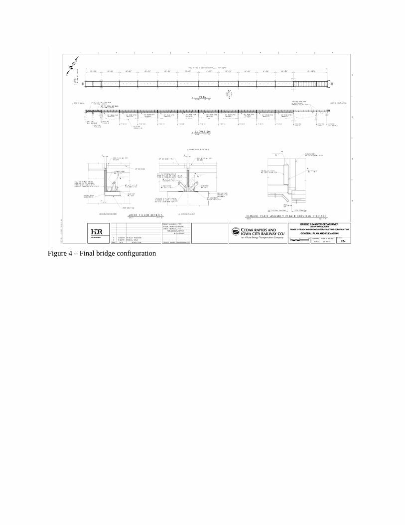
Figure 4 – Final bridge configuration

BRIDGE CONSTRUCTION It was originally planned to begin construction on the new structure in December of 2008 pending receipt
of permits from the Corps, the Iowa DNR, and the City of Cedar Rapids. However, delays in receipt of
the permit from the City of Cedar Rapids delayed the project approximately 6 weeks and construction
began in January 2009.
Figure 5 – Starting construction
The causeway built for removal of the original structure was rebuilt and reconfigured to accommodate
drilling rigs and a crane for construction of the drilled shafts. The first shafts were drilled on January 26,
2009. Due to the late start the work proceeded into the spring months which at times caused difficulties
in handling the river. With a couple short delays due to high water, 7 of the 9 new piers were completed
by April 14, 2009.
Figure 6 – High water
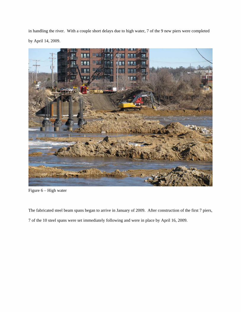
The fabricated steel beam spans began to arrive in January of 2009. After construction of the first 7 piers,
7 of the 10 steel spans were set immediately following and were in place by April 16, 2009.

Figure 7 – East spans complete
Due to varying water levels, it was difficult to extend the causeway from the east all of the way across the
river for construction of piers 8 and 9 (near the west river bank). Therefore, immediately following the
setting of the spans 1-7, the causeway was removed and a new river access was constructed from the west
bank for the construction of piers 8 and 9. After one more brief delay from the river, construction of piers
8 and 9 was completed by June 22, 2009 and the remaining steel spans were also set on June 22, 2009.
Construction of the superstructure was completed June 26, 2009.
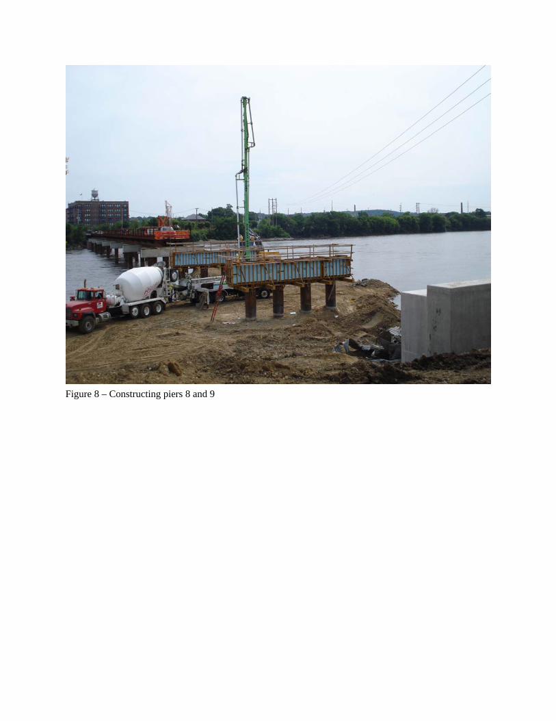
Figure 8 – Constructing piers 8 and 9

Figure 9 – Final superstructure piece
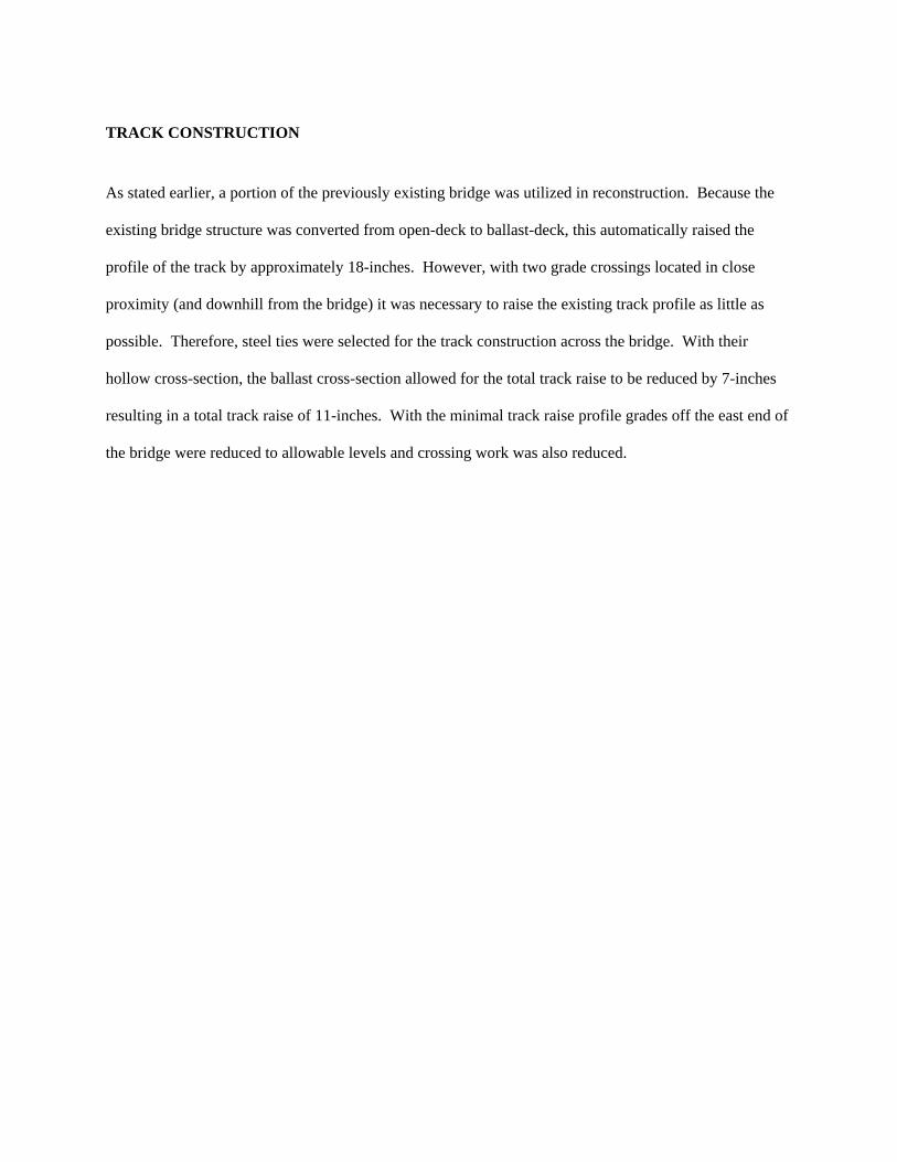
TRACK CONSTRUCTION
As stated earlier, a portion of the previously existing bridge was utilized in reconstruction. Because the
existing bridge structure was converted from open-deck to ballast-deck, this automatically raised the
profile of the track by approximately 18-inches. However, with two grade crossings located in close
proximity (and downhill from the bridge) it was necessary to raise the existing track profile as little as
possible. Therefore, steel ties were selected for the track construction across the bridge. With their
hollow cross-section, the ballast cross-section allowed for the total track raise to be reduced by 7-inches
resulting in a total track raise of 11-inches. With the minimal track raise profile grades off the east end of
the bridge were reduced to allowable levels and crossing work was also reduced.
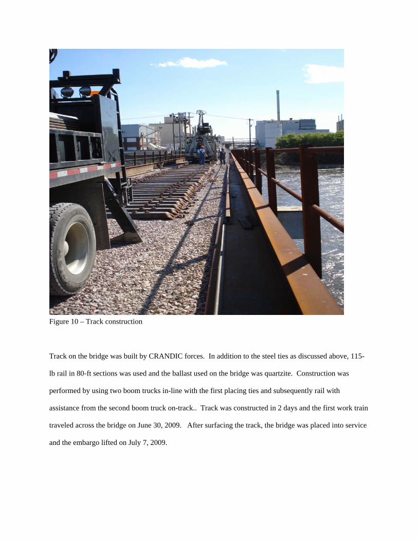
Figure 10 – Track construction
Track on the bridge was built by CRANDIC forces. In addition to the steel ties as discussed above, 115-
lb rail in 80-ft sections was used and the ballast used on the bridge was quartzite. Construction was
performed by using two boom trucks in-line with the first placing ties and subsequently rail with
assistance from the second boom truck on-track.. Track was constructed in 2 days and the first work train
traveled across the bridge on June 30, 2009. After surfacing the track, the bridge was placed into service
and the embargo lifted on July 7, 2009.

F
igure 11 – Tamping and ballast dumping with four salvaged ballast cars.

Figure 12 – Final bridge in place.

List of Figures Page
Figure 1 – Collapsing bridge………………………………………………………………………………
Figure 2 – Collapsed bridge………………………………………………………………………….........
Figure 3 – Salvaging ballast cars…………………………………………………………………………..
Figure 4 – Final bridge configuration...…………………………………………………………………...
Figure 5 – Starting construction…………………………………………………………………………..
Figure 6 – High water………..……………………………………………………………………………
Figure 7 – East spans complete……………………………………………………………………………
Figure 8 – Constructing piers 8 & 9……………………………………………………………………….
Figure 9 – Final superstructure piece……………………………………………………………………...
Figure 10 – Track construction……………………………………………………………………………
Figure 11 – Tamping and ballast dumping with four salvaged ballast cars……………………………….
Figure 12 – Final bridge in place………………………………………………………………………….