cole-parmer laboratory chloride ion ... table of contents cole-parmer laboratory chloride ion...
TRANSCRIPT
Table of Contents1
COLE-PARMERLABORATORY CHLORIDE ION ELECTRODE
INSTRUCTION MANUAL
Cole-Parmer Instrument Company (800)323-4340 Fax:(847)247-2929625 East Bunker Court, Vernon Hills, Illinois 60061
http://www.coleparmer.comEmail: [email protected]
Table of Contents2
TABLE OF CONTENTS
General Instructions .............................................................................................................................3introduction ..................................................................................................................................3required equipment .....................................................................................................................3required solutions ........................................................................................................................3
General Preparation ..............................................................................................................................4electrode preparation ..................................................................................................................4electrode slope check (with pH/mV meter) .................................................................................4electrode slope check (with ion meter) .......................................................................................5
Measurement .........................................................................................................................................5measuring hints ...........................................................................................................................5sample requirements ..................................................................................................................6units of measurement ..................................................................................................................6
Measurement Procedure .....................................................................................................................6direct measurement ....................................................................................................................6direct measurement of chloride (using a pH/mV meter) ............................................................6direct measurement of chloride (using an ion meter) .................................................................8low level chloride determination (using a pH/mV meter) ............................................................9low level chloride determination (using an ion meter) ..............................................................10
Electrode Characteristics ..................................................................................................................10reproducibility ............................................................................................................................10interferences ..............................................................................................................................11removal of various interferences with cisa ................................................................................11complexation .............................................................................................................................12temperature influences .............................................................................................................12electrode response ...................................................................................................................13limits of detection .......................................................................................................................14pH effects ...................................................................................................................................14electrode life ..............................................................................................................................15electrode storage ......................................................................................................................15
Electrode Theory .................................................................................................................................15electrode operation ...................................................................................................................15
Troubleshooting Guide ......................................................................................................................16
Troubleshooting Hints ........................................................................................................................19
Electrode Specifications ....................................................................................................................21
Ordering Information ..........................................................................................................................21
Table of Contents3
COLE-PARMERCHLORIDE ION ELECTRODES
INSTRUCTION MANUAL
GENERAL INSTRUCTIONS
Introduction
The Cole-Parmer Chloride Ion Electrodes are used to quickly, simply, accurately, andeconomically measure chloride ions in aqueous solutions.
Required Equipment
1. A pH/mV meter or an ion meter, either line operated or portable.
2. Semi-logarithmic 4-cycle graph paper for preparing calibration curves when usingthe meter in the mV mode.
3. A magnetic stirrer.
4. The Cole-Parmer Chloride Ion Combination Glass Electrode, Cat. No. 27502-13,or the Cole-Parmer Chloride Ion Combination Epoxy Electrode, Cat No.27504-08.
5. Polishing Paper to polish dirty or etched electrode membranes.
Required Solutions
1. Deionized or distilled water for solution and standard preparation.
2. Cole-Parmer Ionic Strength Adjuster (ISA), 5M NaNO3, Cat. No. 27503-51. Toprepare this solution from your own laboratory stock, half fill a 1000 ml volumetricflask with distilled water and add 425 grams of reagent-grade sodium nitrate,NaNO3. Swirl the flask to dissolve the solid. Fill the flask to the mark with distilledwater, cap, and invert the flask several times to mix the contents. ISA is added atthe rate of 2 ml of ISA to each 100 ml of standard or sample to adjust the ionicstrength to about 0.1M.
3. Cole-Parmer Electrode Filling Solution, 1M KNO3, Cat. No. 27503-75, for both the27502-13 and 27504-08 chloride combination electrodes.
4. Cole-Parmer Chloride Standard, 0.1M NaCl, Cat. No. 27503-08. To prepare thissolution from your own laboratory stock, add 5.84 grams of reagent-gradesodium chloride, NaCl, to a one liter volumetric flask about half-full of distilledwater. Swirl the flask to dissolve the solid. Fill to the mark with distilled water,cap, and upend the flask several times to mix the solution.
Table of Contents4
5. Cole-Parmer Chloride Standard, 1000 ppm Cl-1, Cat. No. 27503-09. To preparethis solution from your own laboratory stock, add 1.65 grams of reagent-gradesodium chloride, NaCl, to a one liter volumetric flask about half-full of distilledwater. Swirl the flask to dissolve the solid. Fill to the mark with distilled water,cap, and upend the flask several times to mix the solution.
6. Cole-Parmer Chloride Standard, 100 ppm Cl-1. To prepare this solution from yourown laboratory stock, add 0.165 grams of reagent-grade sodium chloride, NaCl,to a one liter volumetric flask about half-full of distilled water. Swirl the flask todissolve the solid. Fill to the mark with distilled water, cap, and upend the flaskseveral times to mix the solution.
GENERAL PREPARATION
Electrode Preparation
Remove the rubber cap covering the electrode tip and the rubber insert covering the filling holeof the reference electrode. Fill the combination electrode with the filling solution shipped withthe electrode to a level just below the fill hole. No preparation is required with a sealedreference electrode. Connect the electrode to the proper terminals of the meter asrecommended by the meter manufacturer.
Electrode Slope Check (with pH/mV meter)(check electrode each day)
1. To a 150 ml beaker, add 100 ml of distilled water and 2 ml of ISA. Place thebeaker on a magnetic stirrer and begin stirring at a constant rate. After assuringthat the meter is in the mV mode, lower the electrode tips into the solution.
2. Using a pipet, add 1 ml of 0.1M or 1000 ppm chloride standard to the beaker.When the reading has stabilized, record the millivolt reading.
3. Using a pipet, add 10 ml of the same chloride standard used above to thebeaker. When the reading has stabilized, record the millivolt reading.
4. Determine the difference between the two readings. A difference of 56 ± 2 mVindicates correct electrode operation, assuming the solution temperature isbetween 20° and 25°C. See the TROUBLESHOOTING section if the potentialchange is not within this range.
Slope is defined as the change in potential observed when the concentration changes by afactor of 10.
Table of Contents5
Electrode Slope Check (with ion meter)(check electrode each day)
1. Prepare standard chloride solutions whose concentrations vary by tenfold. Useeither the 0.1M or 1000 ppm chloride standard. Use the serial dilution method forthis preparation.
2. To a 150 ml beaker, add 100 ml of the lower value standard and 2 ml of ISA.Place the beaker on the magnetic stirrer and begin stirring at a constant rate.Lower the electrode tip into the solution. Assure that the meter is in theconcentration mode.
3. Adjust the meter to the concentration of the standard and fix the value in thememory according to the meter manufacturer’s instructions.
4. Rinse the electrode with distilled water and blot dry.
5. To another 150 ml beaker, add 100 ml of the higher value standard and 2 ml ofISA. Place the beaker on the magnetic stirrer and begin stirring at a constantrate. Lower the electrode tip into the solution.
6. Adjust the meter to the concentration of the standard and fix the value in thememory.
7. Read the electrode slope according to the meter manufacturer’s instructions.Correct electrode operation is indicated by a slope of 90-100%. See theTROUBLESHOOTING section if the slope is not within this range.
MEASUREMENT
Measuring Hints
All samples and standards should be at the same temperature for precise measurement. Adifference of 1 degree C in temperature will result in about a 2% measurement error.
Constant, but not violent, stirring is necessary for accurate measurement. Magnetic stirrers cangenerate sufficient heat to change the solution temperature. To counteract this effect, place apiece of insulating material, such as styrofoam sheet, between the stirrer and beaker.
Always rinse the electrode with distilled water and blot dry between measurements. Use aclean, dry tissue to prevent cross-contamination.
For samples with high ionic strength, prepare standards whose composition is similar to thesample.
Always check to see that the membrane is free from air bubbles after immersion into thestandard or sample.
Table of Contents6
Sample Requirements
All samples must be aqueous and not contain organics which can dissolve the epoxy electrodebody and/or the cement bonding the sensing crystal to the electrode body. Infrequentmeasurements in solutions containing methanol, ethanol, benzene, and acetonitrile arepermitted. Highly polar solvents slowly attack the electrode. Please check with Cole-ParmerInstrument Company before using the electrode in other organic solvents.
The temperature of the standard solutions and of the sample solutions should be the same andbelow 50°C.
Interferences should be absent. If they are present, use the procedures found in theInterferences and Electrode Response sections to remove them.
The pH range for the chloride ion electrode is 2-12. Neutralize samples outside this range withacid or base to bring them in range.
Units of Measurement
Chloride concentrations are measured in units of parts per million, equivalents per liter, molesper liter, or any other convenient concentration unit. Table 1 indicates some of theconcentration units.
TABLE 1: Concentration Unit Conversion Factors
ppm Cl-1 moles/liter Cl-1
354.50 1.0 x 10⁻²
35.45 1.0 x 10⁻³
3.55 1.0 x 10⁻⁴
MEASUREMENT PROCEDURE
Direct Measurement
Direct measurement is a simple procedure for measuring a large number of samples. A singlemeter reading is all that is required for each sample. The ionic strength of samples andstandards should be made the same by adjustment with ISA for all chloride solution. Thetemperature of both sample solution and of standard solutions should be the same.
Direct Measurement of Chloride (using a pH/mV meter)
1. By serial dilution of the 0.1M or 1000 ppm standards, prepare 10-2, 10-3, and10-4 M or 100 and 10 ppm chloride standards. Add 2 ml of ISA per 100 ml ofstandard. Prepare standards with a composition similar to the samples if thesamples have an ionic strength above 0.1M.
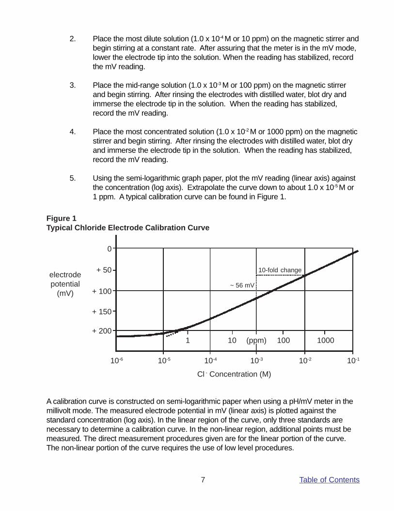
Table of Contents7
2. Place the most dilute solution (1.0 x 10⁻⁴ M or 10 ppm) on the magnetic stirrer andbegin stirring at a constant rate. After assuring that the meter is in the mV mode,lower the electrode tip into the solution. When the reading has stabilized, recordthe mV reading.
3. Place the mid-range solution (1.0 x 10⁻³ M or 100 ppm) on the magnetic stirrerand begin stirring. After rinsing the electrodes with distilled water, blot dry andimmerse the electrode tip in the solution. When the reading has stabilized,record the mV reading.
4. Place the most concentrated solution (1.0 x 10⁻² M or 1000 ppm) on the magneticstirrer and begin stirring. After rinsing the electrodes with distilled water, blot dryand immerse the electrode tip in the solution. When the reading has stabilized,record the mV reading.
5. Using the semi-logarithmic graph paper, plot the mV reading (linear axis) againstthe concentration (log axis). Extrapolate the curve down to about 1.0 x 10⁻⁵ M or1 ppm. A typical calibration curve can be found in Figure 1.
Figure 1Typical Chloride Electrode Calibration Curve
electrodepotential
(mV)
+ 200
10-1
+ 150
+ 100
+ 50
0
1000100101
10-210-310-410-510-6
(ppm)
10-fold change
~ 56 mV
Cl - Concentration (M)
A calibration curve is constructed on semi-logarithmic paper when using a pH/mV meter in themillivolt mode. The measured electrode potential in mV (linear axis) is plotted against thestandard concentration (log axis). In the linear region of the curve, only three standards arenecessary to determine a calibration curve. In the non-linear region, additional points must bemeasured. The direct measurement procedures given are for the linear portion of the curve.The non-linear portion of the curve requires the use of low level procedures.
Table of Contents8
6. To a clean, dry 150 ml beaker, add 100 ml of sample and 2 ml of ISA. Place thebeaker on the magnetic stirrer and begin stirring. Place the electrode tip in thesolution. When the reading has stabilized, record the mV reading. Determine theconcentration directly from the calibration curve.
7. The calibration should be checked every two hours. Assuming no change inambient temperature, place the electrode tip in the mid-range standard. After thereading has stabilized, compare it to the original reading recorded in Step 3above. A reading differing by more than 0.5 mV or a change in the ambienttemperature will necessitate the repetition of Step 2-5 above. A new calibrationcurve should be prepared daily.
Direct Measurement of Chloride (using a ion meter)
1. By serial dilution of the 0.1M or 1000 ppm chloride standard, prepare two chloridestandards whose concentration is near the expected sample concentration.Measure out 100 ml of each standard into individual 150 ml beakers and add 2ml of ISA to each.
2. Place the more dilute solution on the magnetic stirrer and begin stirring at aconstant rate. Assure that the meter is in the concentration mode.
3. Lower the electrode tip into the solution.
4. Adjust the meter to the concentration of the chloride standard and fix the value inthe memory according to the meter manufacturer’s instructions after stabilizationof the reading.
5. Rinse the electrode with distilled water and blot dry.
6. Place the more concentrated solution on the magnetic stirrer and begin stirring ata constant rate.
7. Lower the electrode tip into the solution.
8. Adjust the meter to the concentration of the chloride standard and fix the value inthe memory according to the meter manufacturer’s instructions after stabilizationof the reading.
9. For low level measurements, place the rinsed, dried electrodes into the solutioncontaining 100 ml of distilled water and 2 ml of ISA. After stabilization, fix theblank value in the meter according to the meter manufacturer’s instructions.
10. Place 100 ml of the sample and 2 ml of ISA in a 150 ml beaker, place it on themagnetic stirrer, and begin stirring.
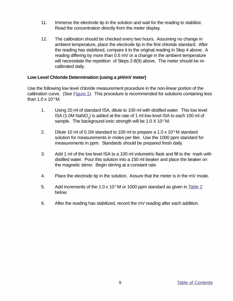
Table of Contents9
11. Immerse the electrode tip in the solution and wait for the reading to stabilize.Read the concentration directly from the meter display.
12. The calibration should be checked every two hours. Assuming no change inambient temperature, place the electrode tip in the first chloride standard. Afterthe reading has stabilized, compare it to the original reading in Step 4 above. Areading differing by more than 0.5 mV or a change in the ambient temperaturewill necessitate the repetition of Steps 2-8(9) above. The meter should be re-calibrated daily.
Low Level Chloride Determination (using a pH/mV meter)
Use the following low level chloride measurement procedure in the non-linear portion of thecalibration curve. (See Figure 1). This procedure is recommended for solutions containing lessthan 1.0 x 10⁻⁴ M.
1. Using 20 ml of standard ISA, dilute to 100 ml with distilled water. This low levelISA (1.0M NaNO3) is added at the rate of 1 ml low level ISA to each 100 ml ofsample. The background ionic strength will be 1.0 X 10⁻² M.
2. Dilute 10 ml of 0.1M standard to 100 ml to prepare a 1.0 x 10⁻² M standardsolution for measurements in moles per liter. Use the 1000 ppm standard formeasurements in ppm. Standards should be prepared fresh daily.
3. Add 1 ml of the low level ISA to a 100 ml volumetric flask and fill to the mark withdistilled water. Pour this solution into a 150 ml beaker and place the beaker onthe magnetic stirrer. Begin stirring at a constant rate.
4. Place the electrode tip in the solution. Assure that the meter is in the mV mode.
5. Add increments of the 1.0 x 10⁻² M or 1000 ppm standard as given in Table 2below.
6. After the reading has stabilized, record the mV reading after each addition.
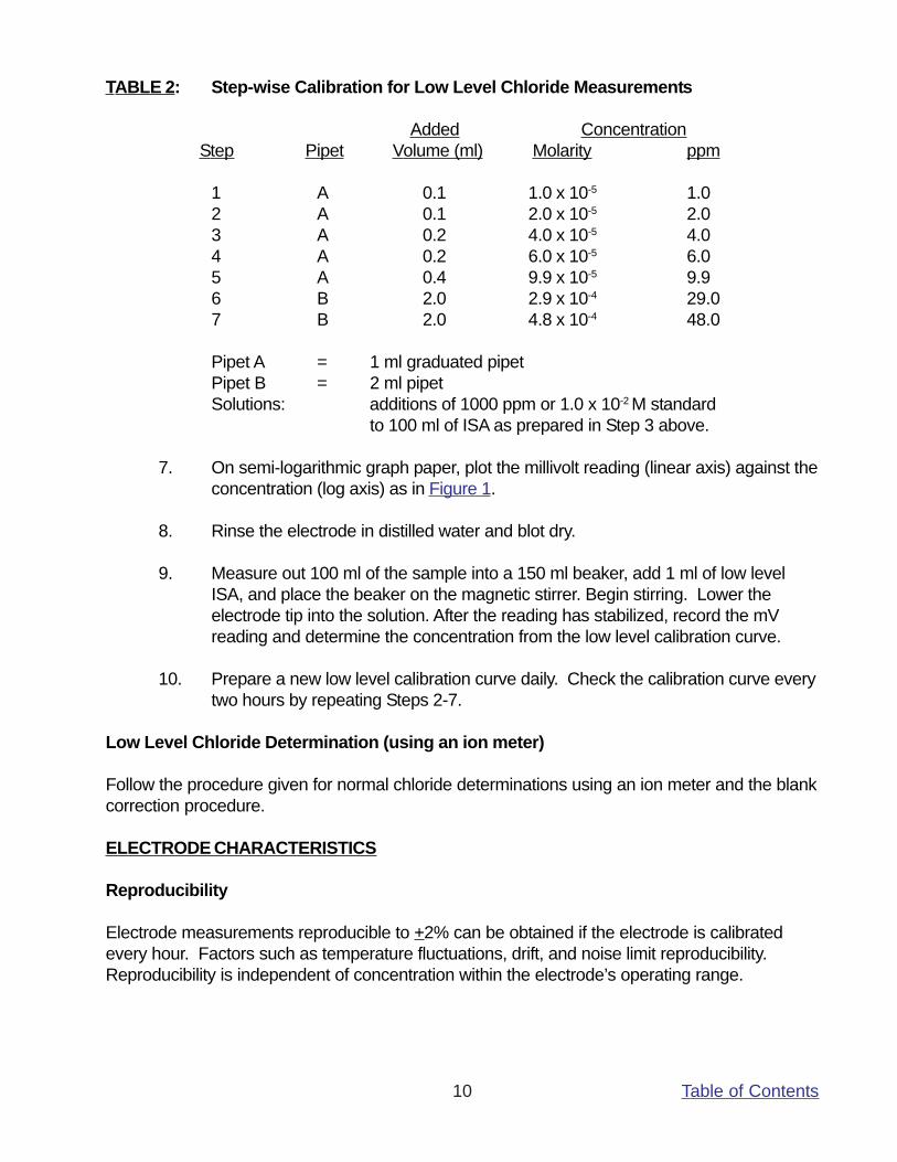
Table of Contents10
TABLE 2: Step-wise Calibration for Low Level Chloride Measurements
Added Concentration Step Pipet Volume (ml) Molarity ppm
1 A 0.1 1.0 x 10⁻⁵ 1.02 A 0.1 2.0 x 10⁻⁵ 2.03 A 0.2 4.0 x 10⁻⁵ 4.04 A 0.2 6.0 x 10⁻⁵ 6.05 A 0.4 9.9 x 10⁻⁵ 9.96 B 2.0 2.9 x 10⁻⁴ 29.07 B 2.0 4.8 x 10⁻⁴ 48.0
Pipet A = 1 ml graduated pipetPipet B = 2 ml pipetSolutions: additions of 1000 ppm or 1.0 x 10⁻² M standard
to 100 ml of ISA as prepared in Step 3 above.
7. On semi-logarithmic graph paper, plot the millivolt reading (linear axis) against theconcentration (log axis) as in Figure 1.
8. Rinse the electrode in distilled water and blot dry.
9. Measure out 100 ml of the sample into a 150 ml beaker, add 1 ml of low levelISA, and place the beaker on the magnetic stirrer. Begin stirring. Lower theelectrode tip into the solution. After the reading has stabilized, record the mVreading and determine the concentration from the low level calibration curve.
10. Prepare a new low level calibration curve daily. Check the calibration curve everytwo hours by repeating Steps 2-7.
Low Level Chloride Determination (using an ion meter)
Follow the procedure given for normal chloride determinations using an ion meter and the blankcorrection procedure.
ELECTRODE CHARACTERISTICS
Reproducibility
Electrode measurements reproducible to +2% can be obtained if the electrode is calibratedevery hour. Factors such as temperature fluctuations, drift, and noise limit reproducibility.Reproducibility is independent of concentration within the electrode’s operating range.
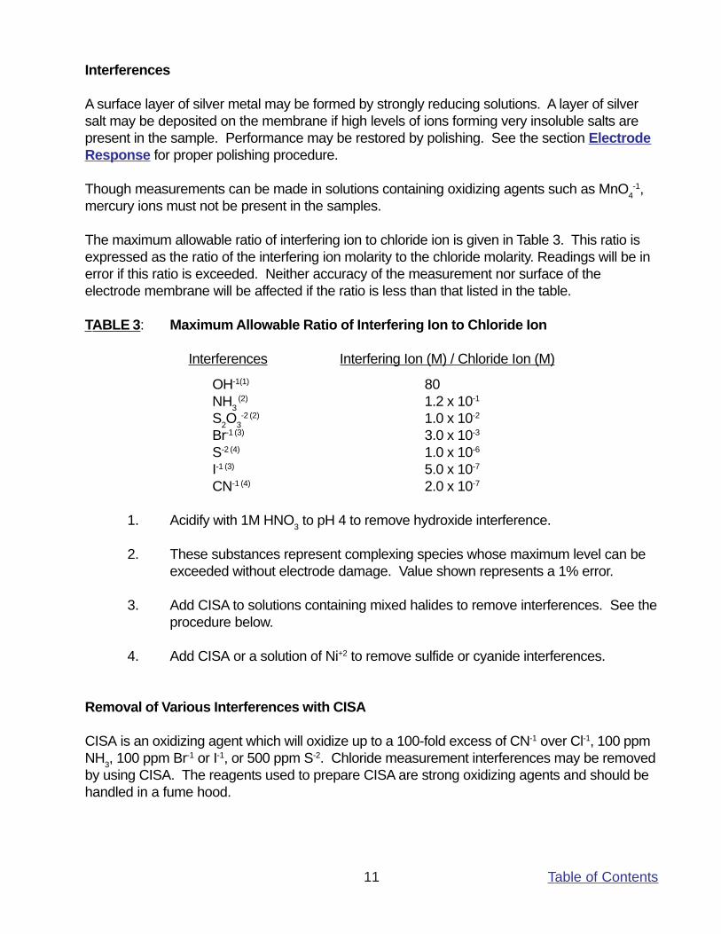
Table of Contents11
Interferences
A surface layer of silver metal may be formed by strongly reducing solutions. A layer of silversalt may be deposited on the membrane if high levels of ions forming very insoluble salts arepresent in the sample. Performance may be restored by polishing. See the section ElectrodeResponse for proper polishing procedure.
Though measurements can be made in solutions containing oxidizing agents such as MnO4-1,
mercury ions must not be present in the samples.
The maximum allowable ratio of interfering ion to chloride ion is given in Table 3. This ratio isexpressed as the ratio of the interfering ion molarity to the chloride molarity. Readings will be inerror if this ratio is exceeded. Neither accuracy of the measurement nor surface of theelectrode membrane will be affected if the ratio is less than that listed in the table.
TABLE 3: Maximum Allowable Ratio of Interfering Ion to Chloride Ion
Interferences Interfering Ion (M) / Chloride Ion (M)
OH-1(1) 80NH3
(2) 1.2 x 10⁻¹
S2O3-2 (2) 1.0 x 10⁻²
Br-1 (3) 3.0 x 10⁻³
S-2 (4) 1.0 x 10⁻⁶
I-1 (3) 5.0 x 10⁻⁷
CN-1 (4) 2.0 x 10⁻⁷
1. Acidify with 1M HNO3 to pH 4 to remove hydroxide interference.
2. These substances represent complexing species whose maximum level can beexceeded without electrode damage. Value shown represents a 1% error.
3. Add CISA to solutions containing mixed halides to remove interferences. See theprocedure below.
4. Add CISA or a solution of Ni+2 to remove sulfide or cyanide interferences.
Removal of Various Interferences with CISA
CISA is an oxidizing agent which will oxidize up to a 100-fold excess of CN-1 over Cl-1, 100 ppmNH3, 100 ppm Br-1 or I-1, or 500 ppm S-2. Chloride measurement interferences may be removedby using CISA. The reagents used to prepare CISA are strong oxidizing agents and should behandled in a fume hood.
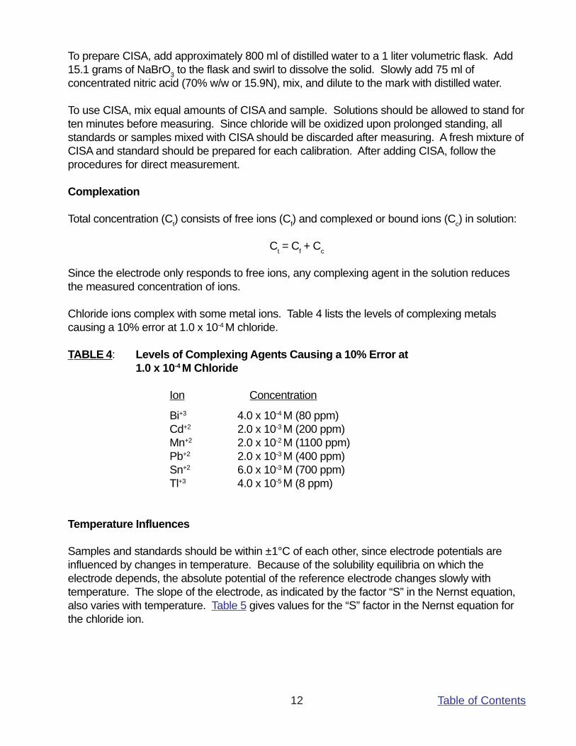
Table of Contents12
To prepare CISA, add approximately 800 ml of distilled water to a 1 liter volumetric flask. Add15.1 grams of NaBrO3 to the flask and swirl to dissolve the solid. Slowly add 75 ml ofconcentrated nitric acid (70% w/w or 15.9N), mix, and dilute to the mark with distilled water.
To use CISA, mix equal amounts of CISA and sample. Solutions should be allowed to stand forten minutes before measuring. Since chloride will be oxidized upon prolonged standing, allstandards or samples mixed with CISA should be discarded after measuring. A fresh mixture ofCISA and standard should be prepared for each calibration. After adding CISA, follow theprocedures for direct measurement.
Complexation
Total concentration (Ct) consists of free ions (Cf) and complexed or bound ions (Cc) in solution:
Ct = Cf + Cc
Since the electrode only responds to free ions, any complexing agent in the solution reducesthe measured concentration of ions.
Chloride ions complex with some metal ions. Table 4 lists the levels of complexing metalscausing a 10% error at 1.0 x 10⁻⁴ M chloride.
TABLE 4: Levels of Complexing Agents Causing a 10% Error at1.0 x 10-4 M Chloride
Ion Concentration
Bi+3 4.0 x 10⁻⁴ M (80 ppm)Cd+2 2.0 x 10⁻³ M (200 ppm)Mn+2 2.0 x 10⁻² M (1100 ppm)Pb+2 2.0 x 10⁻³ M (400 ppm)Sn+2 6.0 x 10⁻³ M (700 ppm)Tl+3 4.0 x 10⁻⁵ M (8 ppm)
Temperature Influences
Samples and standards should be within ±1°C of each other, since electrode potentials areinfluenced by changes in temperature. Because of the solubility equilibria on which theelectrode depends, the absolute potential of the reference electrode changes slowly withtemperature. The slope of the electrode, as indicated by the factor “S” in the Nernst equation,also varies with temperature. Table 5 gives values for the “S” factor in the Nernst equation forthe chloride ion.
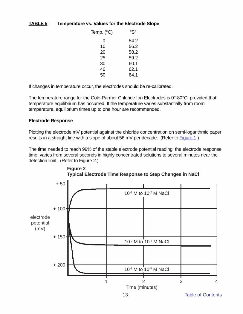
Table of Contents13
TABLE 5: Temperature vs. Values for the Electrode Slope
Temp. (°C) “S”
0 54.210 56.220 58.225 59.230 60.140 62.150 64.1
If changes in temperature occur, the electrodes should be re-calibrated.
The temperature range for the Cole-Parmer Chloride Ion Electrodes is 0°-80°C, provided thattemperature equilibrium has occurred. If the temperature varies substantially from roomtemperature, equilibrium times up to one hour are recommended.
Electrode Response
Plotting the electrode mV potential against the chloride concentration on semi-logarithmic paperresults in a straight line with a slope of about 56 mV per decade. (Refer to Figure 1.)
The time needed to reach 99% of the stable electrode potential reading, the electrode responsetime, varies from several seconds in highly concentrated solutions to several minutes near thedetection limit. (Refer to Figure 2.)
Figure 2Typical Electrode Time Response to Step Changes in NaCl
electrodepotential
(mV)
+ 200
+ 150
+ 100
+ 50
4321Time (minutes)
10-3 M to 10-2 M NaCl
10-3 M to 10-4 M NaCl
10-3 M to 10-5 M NaCl
Table of Contents14
A drifting potential reading or a decrease in electrode slope may mean that the electrodemembrane needs polishing.
To polish the membrane:
1. If using polishing paper, cut off a 1-2" piece and place it face up on the labbench.
2. Put a few drops of distilled or deionized water in the center of the paper.
3. Holding the paper (cotton) steady with one hand, bring the membrane of theelectrode down perpendicular to the paper and, with a slight swirling motion,gently polish the tip of the electrode against the surface of the polishing paper(cotton) for a few seconds.
4. Rinse the electrode surface with distilled or deionized water and soak theelectrode tip in standard solution for about five minutes before use.
5. If using jeweller’s rouge, place a cotton ball on the table top and flatten it usingthe bottom of a beaker.
6. Put 1-2 drops of distilled or deionized water in the center of the cotton pad.
7. Add a small amount of jeweller’s rouge to the damp cotton.
8. Continue with Steps 3 and 4 above.
Limits of Detection
The upper limit of detection in pure sodium chloride solutions is 1M. In the presence of otherions, the upper limit of detection is above 1.0 x 10⁻¹ M chloride, but two factors influence thisupper limit. Both the possibility of a liquid junction potential developing at the referenceelectrode and the salt extraction effect influence this upper limit. Some salts may extract intothe electrode membrane at high salt concentrations, causing deviation from the theoreticalresponse. Either dilute samples between 1M and 1.0 x 10⁻¹ M or calibrate the electrode at 4 or5 intermediate points.
The lower limit of detection is influenced by the slight water solubility of the electrode pellet.Refer to Figure 1 for a comparison of the theoretical response to the actual response at lowlevels of chloride. Chloride measurements below 10-4 M Cl-1 should employ low levelprocedures.
pH Effects
Hydroxide ion interferes with measurements of low levels of chloride although the electrode canbe used over a reasonable pH range. Table 3 should be used to determine the minimum pH atwhich low level chloride measurements can be made without more than a 10% error due tohydroxide ion interference.
Table of Contents15
Electrode Life
The chloride electrode will last six months in normal laboratory use. On-line measurementsmight shorten operational lifetime to several months. In time, the response time will increaseand the calibration slope will decrease to the point calibration is difficult and electrodereplacement is required.
Electrode Storage
The Cole-Parmer Chloride Electrodes may be stored for short periods of time in 1.0 x 10⁻² Mchloride solution. For longer storage (longer than two weeks), rinse and dry the sensing pelletand cover the membrane tip with any protective cap shipped with the electrode. The referenceportion of the combination electrode should be drained of filling solution, if refillable, and therubber insert placed over the filling hole.
ELECTRODE THEORY
Electrode Operation
The Cole-Parmer Chloride Ion Electrodes are composed of a glass or an epoxy body and asilver chloride/silver sulfide membrane. When the membrane is in contact with a solutioncontaining chloride ions, an electrode potential develops across the membrane. This electrodepotential is measured against a constant reference potential, using a pH/mV meter or an ionmeter. The level of chloride ions, corresponding to the measured potential, is described by theNernst equation:
E = Eo - S logXwhere:
E = measured electrode potentialEo = reference potential (a constant)S = electrode slope (~56 mV/decade)X = level of chloride ions in solution
The activity, X, represents the effective concentration of the ions in solution. The activity isrelated to the free ion concentration, Cf, by the activity coefficient, γ, by:
X = γ Cf
Activity coefficients vary, depending on total ionic strength, I, defined as:
I = ½ Σ CxZx2
where:Cx = concentration of ion XZx = charge of ion XΣ = sum of all of the types of ions in the solution
Table of Contents16
In the case of high and constant ionic strength relative to the sensed ion concentration, theactivity coefficient, γ, is constant and the activity, X, is directly proportional to the concentration.
To adjust the background ionic strength to a high and constant value, ionic strength adjuster(ISA) is added to samples and standards. The recommended ISA for chloride is NaNO3.Solutions other than this may be used as ionic strength adjusters as long as ions that theycontain do not interfere with the electrode’s response to chloride ions. Samples with high ionicstrength (greater than 0.1M) do not need ISA added and standards for these solutions shouldbe prepared with a composition similar to the samples.
The reference electrode must also be considered. When two solutions of different compositionare brought into contact with one another, liquid junction potentials arise. Millivolt potentialsoccur from the inter-diffusion of ions in the two solutions. Electrode charge will be carriedunequally across the solution boundary resulting in a potential difference between the twosolutions, since ions diffuse at different rates. When making measurements, it is important toremember that this potential be the same when the reference is in the standardizing solution aswell as in the sample solution or the change in liquid junction potential will appear as an error inthe measured electrode potential.
The composition of the liquid junction filling solution in the reference electrode is mostimportant. The speed with which the positive and negative ions in the filling solution diffuse intothe sample should be equitransferent. No junction potential can result if the rate at whichpositive and negative charge carried into the sample is equal.
Strongly acidic (pH=0-2) and strongly basic (pH=12-14) solutions are particularly troublesome tomeasure. The high mobility of hydrogen and hydroxide ions in samples make it impossible tomask their effect on the junction potential with any concentration of an equitransferent salt.One must either calibrate the electrodes in the same pH range as the sample or use a knownincrement method for ion measurement.
TROUBLESHOOTING GUIDE
The goal of troubleshooting is the isolation of a problem through checking each of the systemcomponents in turn: the meter, the glassware, the electrode, the standards & reagents, thesample, and the technique.
Meter
The meter may be checked by following the check-out procedure in the instrument instructionmanual.
Glassware
Clean glassware is essential for good measurement. Be sure to wash the glassware well with amild detergent and rinse very well with distilled or deionized water. Clean glassware will drainwithout leaving water droplets behind.
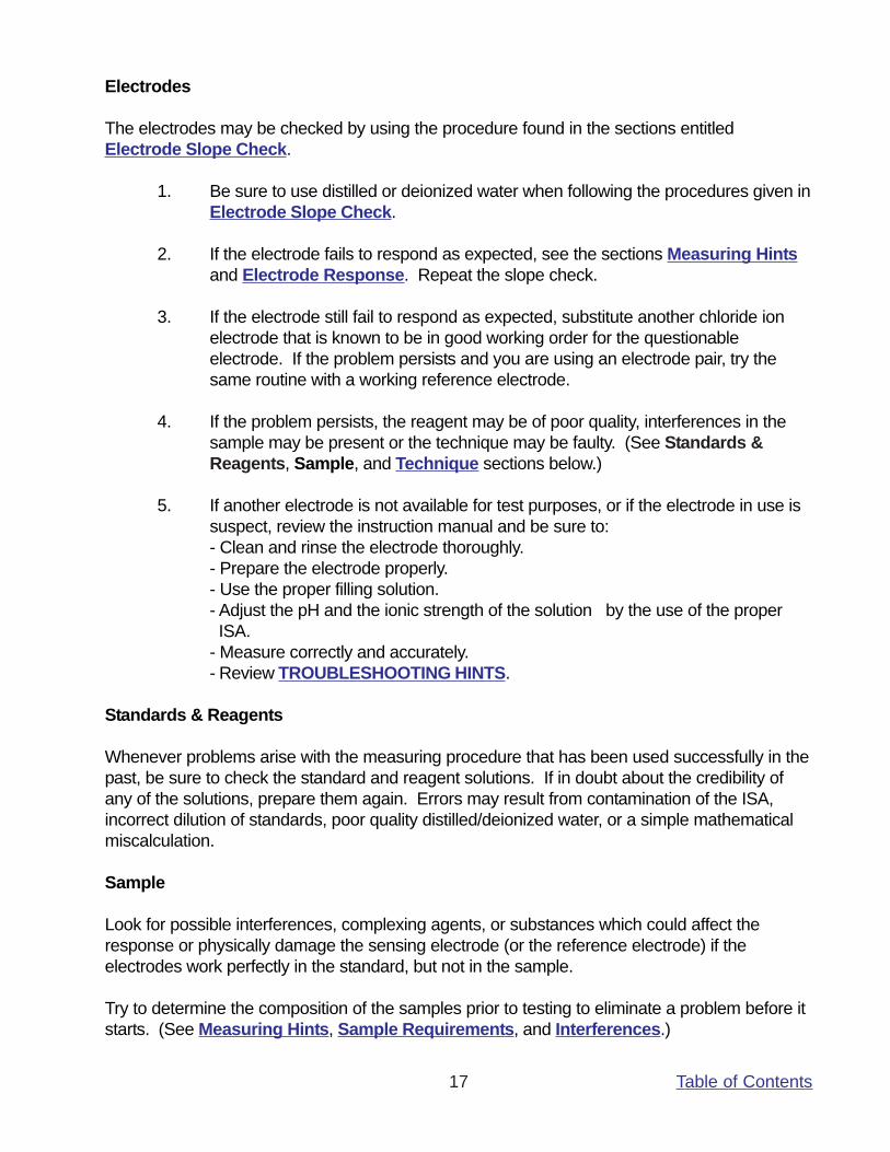
Table of Contents17
Electrodes
The electrodes may be checked by using the procedure found in the sections entitledElectrode Slope Check.
1. Be sure to use distilled or deionized water when following the procedures given inElectrode Slope Check.
2. If the electrode fails to respond as expected, see the sections Measuring Hintsand Electrode Response. Repeat the slope check.
3. If the electrode still fail to respond as expected, substitute another chloride ionelectrode that is known to be in good working order for the questionableelectrode. If the problem persists and you are using an electrode pair, try thesame routine with a working reference electrode.
4. If the problem persists, the reagent may be of poor quality, interferences in thesample may be present or the technique may be faulty. (See Standards &Reagents, Sample, and Technique sections below.)
5. If another electrode is not available for test purposes, or if the electrode in use issuspect, review the instruction manual and be sure to:- Clean and rinse the electrode thoroughly.- Prepare the electrode properly.- Use the proper filling solution.- Adjust the pH and the ionic strength of the solution by the use of the proper ISA.- Measure correctly and accurately.- Review TROUBLESHOOTING HINTS.
Standards & Reagents
Whenever problems arise with the measuring procedure that has been used successfully in thepast, be sure to check the standard and reagent solutions. If in doubt about the credibility ofany of the solutions, prepare them again. Errors may result from contamination of the ISA,incorrect dilution of standards, poor quality distilled/deionized water, or a simple mathematicalmiscalculation.
Sample
Look for possible interferences, complexing agents, or substances which could affect theresponse or physically damage the sensing electrode (or the reference electrode) if theelectrodes work perfectly in the standard, but not in the sample.
Try to determine the composition of the samples prior to testing to eliminate a problem before itstarts. (See Measuring Hints, Sample Requirements, and Interferences.)
Table of Contents18
Technique
Be sure that the electrode’s limit of detection has not been exceeded. Be sure that the analysismethod is clearly understood and is compatible with the sample.
Refer to the instruction manual again. Reread GENERAL PREPARATION and ELECTRODECHARACTERISTICS.
If trouble still persists, call Cole-Parmer Instrument Company at 1-800-323-4340 and ask for theTechnical Services Department.
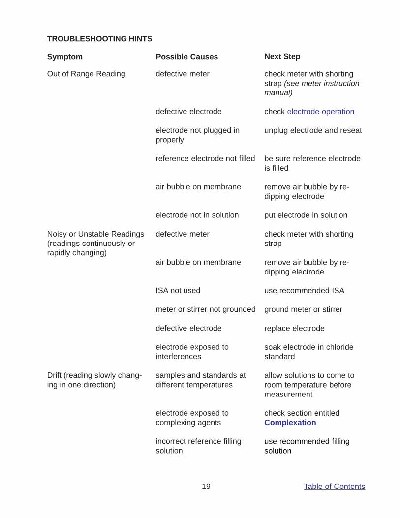
Table of Contents19
TROUBLESHOOTING HINTS
Symptom Possible Causes Next Step
Out of Range Reading
Noisy or Unstable Readings(readings continuously orrapidly changing)
Drift (reading slowly chang-ing in one direction)
defective meter
defective electrode
electrode not plugged inproperly
reference electrode not filled
air bubble on membrane
electrode not in solution
defective meter
air bubble on membrane
ISA not used
meter or stirrer not grounded
defective electrode
electrode exposed tointerferences
samples and standards atdifferent temperatures
electrode exposed tocomplexing agents
incorrect reference fillingsolution
check meter with shortingstrap (see meter instructionmanual)
check electrode operation
unplug electrode and reseat
be sure reference electrodeis filled
remove air bubble by re-dipping electrode
put electrode in solution
check meter with shortingstrap
remove air bubble by re-dipping electrode
use recommended ISA
ground meter or stirrer
replace electrode
soak electrode in chloridestandard
allow solutions to come toroom temperature beforemeasurement
check section entitledComplexation
use recommended fillingsolution
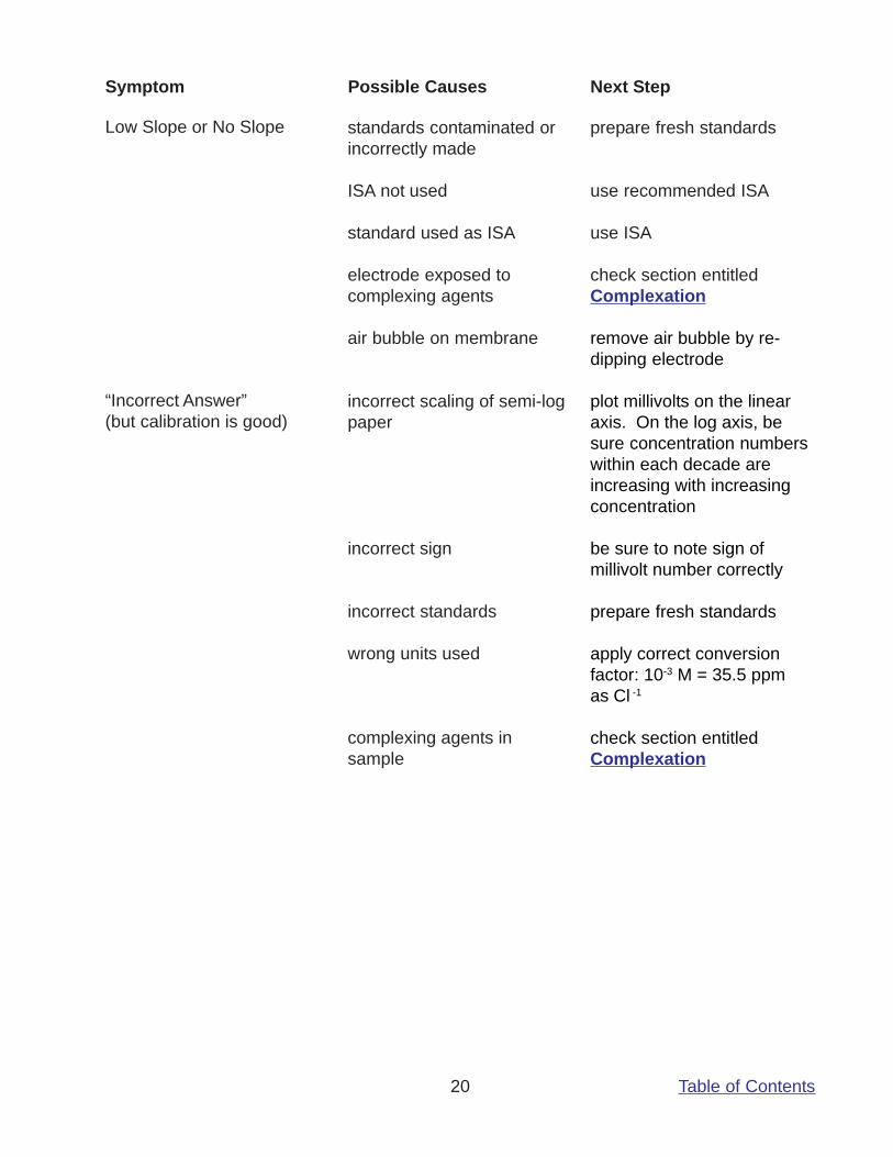
Table of Contents20
Symptom Possible Causes Next Step
Low Slope or No Slope
“Incorrect Answer”(but calibration is good)
standards contaminated orincorrectly made
ISA not used
standard used as ISA
electrode exposed tocomplexing agents
air bubble on membrane
incorrect scaling of semi-logpaper
incorrect sign
incorrect standards
wrong units used
complexing agents insample
prepare fresh standards
use recommended ISA
use ISA
check section entitledComplexation
remove air bubble by re-dipping electrode
plot millivolts on the linearaxis. On the log axis, besure concentration numberswithin each decade areincreasing with increasingconcentration
be sure to note sign ofmillivolt number correctly
prepare fresh standards
apply correct conversionfactor: 10-3 M = 35.5 ppmas Cl -1
check section entitledComplexation
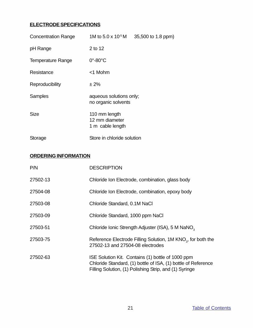
Table of Contents21
ELECTRODE SPECIFICATIONS
Concentration Range 1M to 5.0 x 10⁻⁵ M 35,500 to 1.8 ppm)
pH Range 2 to 12
Temperature Range 0°-80°C
Resistance <1 Mohm
Reproducibility ± 2%
Samples aqueous solutions only;no organic solvents
Size 110 mm length12 mm diameter1 m cable length
Storage Store in chloride solution
ORDERING INFORMATION
P/N DESCRIPTION
27502-13 Chloride Ion Electrode, combination, glass body
27504-08 Chloride Ion Electrode, combination, epoxy body
27503-08 Chloride Standard, 0.1M NaCl
27503-09 Chloride Standard, 1000 ppm NaCl
27503-51 Chloride Ionic Strength Adjuster (ISA), 5 M NaNO3
27503-75 Reference Electrode Filling Solution, 1M KNO3, for both the27502-13 and 27504-08 electrodes
27502-63 ISE Solution Kit. Contains (1) bottle of 1000 ppmChloride Standard, (1) bottle of ISA, (1) bottle of ReferenceFilling Solution, (1) Polishing Strip, and (1) Syringe