coke characterization on hzsm-5, fe/zsm-5, ni/zsm-5, and...
TRANSCRIPT
IN DEGREE PROJECT CHEMICAL SCIENCE AND ENGINEERING,SECOND CYCLE, 30 CREDITS
, STOCKHOLM SWEDEN 2018
Coke characterization on
HZSM-5, Fe/ZSM-5, Ni/ZSM-5,
and Fe-Ni/ZSM-5 from Catalytic
Fast Pyrolysis of Biomass
ISA DUMAN
KTH ROYAL INSTITUTE OF TECHNOLOGY
SCHOOL OF CHEMICAL SCIENCE AND ENGINEERING

KTH Royal Institute of Technology
School of Chemical Science and Engineering
Master thesis
Coke characterization on HZSM-5,
Fe/ZSM-5, Ni/ZSM-5, and Fe-Ni/ZSM-5
from Catalytic Fast Pyrolysis of Biomass
Author: Isa Duman
Supervisor: Henry Persson
Examiner: Professor Lars J. Pettersson
KTH Royal Institute of Technology
Department of Chemical Engineering
SE - 100 44 Stockholm
Sweden

Abstract
The combustion of fossil fuels has for a long time been a problem from an environmental and
sustainability point of view, especially when it comes to the emissions of atmospheric carbon di-
oxide. The environmental concern has for instance shifted the attention towards finding new sus-
tainable alternatives for producing chemicals and fuels, as a substitute to today’s dependence on
fossil based crude oil. Catalytic Fast Pyrolysis of biomass is an excellent way to produce valuable
chemicals and fuels using renewable resources. However, the process has some drawbacks, for
example rapid deactivation of catalysts due to coke formation. Little is known about the charac-
teristics of the formation of catalytic coke from pyrolysis processes, which should be a vital con-
cern in future industrial processes. This thesis is dedicated to investigate the chemical coke char-
acteristics found on zeolitic catalysts. Four zeolites of the type ZSM-5 were chosen for this thesis
to deduce any chemical differences in the coke: HZSM-5, Fe/ZSM-5, Ni/ZSM-5, and Fe-Ni/ZSM-
5. The coke were characterized by TGA, GC/MS, and FTIR.
The results show that Fe/ZSM-5 produced the highest amount of coke compared to the other zeo-
lites, where HZSM-5 had the lowest amount of coke formation. The coke consisted mainly of
aromatic and cyclic hydrocarbons, dominated by polycyclic aromatic hydrocarbons. The content
of ketones and alcohols in the coke found on HZSM-5 was higher compared to the metal-doped
zeolites, while the formation of naphthalenes was lower. The FTIR results also show that coke was
mainly comprised of aromatic hydrocarbons. However, traces of alkanes and alkenes reveal that
the coke may have a greater variety than the GC/MS analysis suggests.
The results show interesting features when metals are introduced to the zeolitic structure, at least
when it comes to coke formation. The metal-doping of zeolites certainly seems to alter the chem-
istry of the catalytic reactions, compared to the parent zeolite. The differences in the chemical
characteristics found in the coke are certainly interesting, and it could mean that the chemistry of
the bio-oil also varies depending on the metals chosen for the ZSM-5. The new properties that
metals introduce to the parent catalyst may open up new possibilities in industrial catalytic pro-
cesses, and allow industries to take more advantage of the great benefits that biomass has to offer.
Keywords: Aromatic Hydrocarbons; Biomass; Bio-Oil; Catalytic Fast Pyrolysis; Coke; ZSM-5.
Sammanfattning
Förbränning av fossila bränslen har under lång tid utgjort ett problem ur miljö- och hållbarhets-
synpunkt, i synnerhet gällande utsläppen av koldioxid. En större miljömedvetenhet har gett upp-
hov till sökandet efter nya råvaror för att framställa bränslen och kemikalier, utan att förlita sig på
fossil råolja. Katalytisk pyrolys av biomassa är ett utmärkt sätt att framställa värdefulla kemikalier
från förnybara källor. Processen står dock inför en del tekniska utmaningar, bland annat en snabb
deaktivering av använda katalysatorer genom koksning. Målet med detta examensarbete är att un-
dersöka den kemiska sammansättningen av koks, som bildats på zeolitkatalysatorerna. Mer speci-
fikt, att försöka undersöka huruvida den kemiska sammansättningen av koks skiljer sig mellan
katalysatorn HZSM-5 och metalldopad HZSM-5. Fyra katalysatorer valdes för detta examensar-
bete, nämligen HZSM-5, Fe/ZSM-5, Ni/ZSM-5 och Fe-Ni/ZSM-5. Kokset har analyserats genom
termogravimetrisk analys (TGA), gaskromatograf kopplad med en masspektrometer (GC/MS),
samt Fourier-transform-infraröd-spektroskopi (FTIR).
Resultaten visar att Fe/ZSM-5 bildade en större mängd koks jämfört med de andra zeoliterna,
varpå HZSM-5 hade lägst halt koks. Utöver detta bestod kokset till största del av aromatiska- och
cykliska kolväten, speciellt polycykliska aromatiska kolväten. Innehållet av ketoner och alkoholer
i kokset var störst för HZSM-5, medan bildandet av naftalenföreningar ökade för de metalldopade
zeoliterna. FTIR-analysen gav även upphov till signaler som är signifikanta för både alkaner och
alkener. Därför kan det innebära att kokset innehar en större kemisk variation än vad GC/MS-
analysen påvisade.
Resultaten visar intressanta egenskaper hos metallmodifierade zeoliter, i synnerhet gällande koks-
bildning. Det verkar som att de metalldopade zeoliterna påverkar de katalytiska reaktionerna som
sker i katalysatorn, jämfört med den obehandlade katalysatorn. Skillnaderna i den kemiska sam-
mansättningen hos kokset för de olika katalysatorerna är definitivt intressant och kan indikera att
det även kan föreligga skillnader i den kemiska sammansättningen hos bio-olja, beroende på vilken
metall ZSM-5 har behandlas med. De nya egenskaperna som metaller bidrar med till ZSM-5 kan
öppna upp nya möjligheter i industriella katalytiska processer, vilket även kan medföra att indu-
strier bättre kan ta tillvara på de fantastiska egenskaper biomassa innehar.
Nyckelord: Aromatiska kolväten; Biomassa; Bio-Olja; Katalytisk Pyrolys; Koks; ZSM-5.
ACKNOWLEDGEMENTS
I would like to express my gratitude to everyone that have showed me support during the Master
thesis, from fellow graduate- and undergraduate students to professors at both the Department of
Material Science & Engineering and the Department of Chemical Engineering at KTH Stockholm.
A special thanks to my supervisor, Henry Persson from the Material Science & Engineering at
KTH Stockholm, for the valuable help and guidance that he provided me whenever I came across
an obstacle. The interest he showed in my work was really encouraging. I would also like to thank
my examiner, Professor Lars J. Pettersson from the Department of Chemical Engineering at KTH
Stockholm, for sharing his knowledge which inspired me throughout the work. Thanks to Magnus
Johnson from the Division of Surface and Corrosion Science at KTH Stockholm for helping me
with the FTIR-analysis. Finally, I would also like to thank Nanta Sophonrat and Panagiotis Evan-
gelopoulos for helping me to get familiar with the Gas Chromatography/Mass Spectrometry sys-
tem used at the Department of Material Science & Engineering.
Isa Duman
Stockholm, January 2018
NOMENCLATURE
In this section, the abbreviations used in the Master thesis are listed below.
Abbreviations
ATR Attenuated Total Reflection
BET Brunauer-Emmett-Teller
BTEX Benzene, Toluene, Ethylbenzene, and Xylene
CFP Catalytic Fast Pyrolysis
DCM Dichloromethane
FCC Fluid Catalytic Cracking
FTIR Fourier Transform Infrared
GC/MS Gas Chromatography/Mass Spectrometry
HF Hydrofluoric Acid
HPLC High Performance Liquid Chromatography
LCO Light Cycle Oil
MAH Monocyclic Aromatic Hydrocarbon
PAH Polycyclic Aromatic Hydrocarbon
Pyr-FTIR Pyridine Fourier Transform Infrared
TGA Thermogravimetric Analysis
TEM Transmission Electron Microscopy
TOS Time-on-Stream
WHSV Weight Hourly Space Velocity
TABLE OF CONTENTS
1 INTRODUCTION .................................................................................................................. 1
1.1 Background ...................................................................................................................... 1
1.2 Purpose of study ............................................................................................................... 2
2 THEORETICAL BACKGROUND ....................................................................................... 5
2.1 Fundamentals of pyrolysis ............................................................................................... 5
2.2 Fluid Catalytic Cracking (FCC) ....................................................................................... 8
2.3 Zeolites as catalysts .......................................................................................................... 9
2.3.1 Properties of zeolites ................................................................................................. 9
2.3.2 Choice of Catalyst ................................................................................................... 11
2.4 Coke composition and its formation .............................................................................. 11
2.4.1 Coking of catalysts during FCC .............................................................................. 12
2.4.2 Dealumination associated with FCC ....................................................................... 13
2.4.3 Effects of aluminum content on the formation of aromatics ................................... 14
2.4.4 Coking on Zeolites during CFP of Biomass ............................................................ 15
2.4.5 Fe/ZSM-5 and Ni/ZSM-5 ........................................................................................ 16
2.5 Fourier Transform Infrared Spectroscopy (FTIR).......................................................... 20
2.5.1 Working principle of FTIR ..................................................................................... 23
2.6 Thermogravimetric Analysis (TGA) .............................................................................. 24
3 MATERIALS AND METHODS ......................................................................................... 25
3.1 Choice of analyses techniques ........................................................................................ 25
3.2 The Biomass Pyrolysis Process ...................................................................................... 25
3.3 Catalyst preparation and properties ................................................................................ 26
3.4 Separation of coke and zeolite........................................................................................ 26
3.5 GC/MS ........................................................................................................................... 28
3.6 FTIR ............................................................................................................................... 28
3.7 TGA ................................................................................................................................ 29
3.8 Delimitations .................................................................................................................. 30
4 RESULTS AND DISCUSSION .......................................................................................... 33
4.1 TGA ................................................................................................................................ 33
4.2 GC/MS ........................................................................................................................... 35
4.2.1 HZSM-5 .................................................................................................................. 36
4.2.2 Fe/ZSM-5 ................................................................................................................ 37
4.2.3 Ni/ZSM-5 ................................................................................................................ 38
4.2.4 Fe-Ni/ZSM-5 ........................................................................................................... 39
4.2.5 Distribution of aromatic and cyclic compounds...................................................... 40
4.2.6 Type of compounds in the coke .............................................................................. 41
4.3 FTIR ............................................................................................................................... 43
4.4 Final remarks .................................................................................................................. 45
5 CONCLUSIONS .................................................................................................................. 47
6 RECOMMENDATIONS AND FUTURE WORK .............................................................. 49
7 REFERENCES ..................................................................................................................... 51
1
1 INTRODUCTION
This introductory part aims to provide the reader with the background information of this pro-
ject as well as to describe its purpose in order to motivate its importance. Additionally, there
will also be a part that deals with the suggested methodology for the experimental phase and
delimitations. However, these parts will be discussed later in this study.
1.1 Background
The focus on producing fuels and chemicals in a sustainable manner in order to mitigate CO2-
emissions is becoming more and more important. Biomass is a highly attractive feedstock due
to its wide range of applicability, one of which includes renewable fuel production. While the
burning of fossil fuels contributes to the increased concentration in atmospheric carbon dioxide,
the combustion of biomass is CO2-neutral because it does not increase the net level of CO2 in
the atmosphere. The harnessing of biomass to manufacture various products, which are nor-
mally based on fossil crude oil, represents a great vision to combat the environmental problems
associated with crude oil treatment. An interesting pathway to convert biomass into useful
chemicals is catalytic fast pyrolysis. As the name suggests, the process includes the rapid py-
rolysis of biomass in order to produce valuable organic compounds such as bio-oil. Biomass is
comprised of cellulose, hemicellulose, and lignin, the former two containing linear- and
branched polymers of sugars respectively. The lignin however has a more complex structure
that contains aromatic species, which in terms of bio-oil-production is very interesting (Aho et
al. 2013). For example, aromatic species such as toluene and xylene, which can be found in bio-
oil, can be harnessed and mixed in fuel blends immediately (Mullen and Boateng 2015). How-
ever, the bio-oil itself cannot be utilized without downstream treatment after the fast pyrolysis
since it contains oxygenated compounds and water originating from pyrolysis products, which
gives the oil some unpleasant characteristics. These compounds are responsible for making the
oil more acidic, increasing its viscosity, decreasing its chemical stability and heating value, and
making it more corrosive (Aho et al. 2013) (Wang et al. 2016).
To enable the utilization of bio-oil in modern-day applications, it is essential that the bio-oil is
upgraded in order to convert unwanted species such as oxygenated compounds into more valu-
able products. Catalytic fast pyrolysis of biomass, using zeolites as catalysts, is an excellent
way to accomplish such upgrading. The use of zeolites in oil-treatment is not a new concept. It
has been extensively used in the petroleum industry for producing high-value products such as
gasoline from hydrocarbons found in crude-oil. This is often accomplished through a process
known as Fluid Catalytic Cracking, which uses zeolites under a high-temperature environment
to crack hydrocarbons in the crude oil (Komvokis et al. 2016). It is important to note that crude-
oil normally contains a low amount of oxygenated compounds, which means that the require-
ments of deoxygenation is not as extensive in the petroleum industry compared to bio-oil. For
example, elemental analysis shows that the oxygen content of crude oil is between 0.05-1.5 wt-
% while the same number for bio-oil is about 35 wt-% (Jukić 2013) (Czernik and Bridgwater
2
2004). However, there is a common problem that is shared among the catalytic cracking of
crude oil and bio oil, namely catalyst deactivation. The catalyst can be deactivated in different
ways, one of which consists of deactivation by coking. The coke being a carbonaceous mass
that can deposit on the catalysts needs to be burned of repeatedly. This is problematic because
when the catalyst is subjected to high temperatures, irreversible damage is caused, which de-
crease the catalyst activity over time (Cerqueira et al. 2008). To combat this problem, there is
a need for better understanding of coke formation and composition on the zeolite. By studying
the coke, it might be possible to better understand the precursors of coke and give some insight
of how it can be controlled.
1.2 Purpose of study
As coke formation deactivates the catalyst, it is vital to have a better understanding of the coke
characteristics. By better understanding catalyst coking, e.g. its chemical composition and prob-
able precursors, it might be possible to better control coke formation in the future. In the FCC
process, the energy contained in the coke is utilized to sustain the endothermic cracking reac-
tions, by combusting it in a regeneration step. However, severe coking in general means that
catalysts often need to be regenerated, which can lead to more pronounced catalyst damage
such as sintering and dealumination. This has the effect of shortening the catalyst life time. It
is therefore important to investigate the coking behavior of catalysts further by proper zeolite
modifications.
A commonly used zeolite in catalytic fast pyrolysis of biomass is ZSM-5. Also, it is not unusual
to find papers that have investigated transition-metal-treated ZSM-5. These papers mostly focus
on the capability of the parent- and the metal treated ZSM-5 to produce aromatic hydrocarbons
while at the same time reducing the content of oxygenated compounds. However, not as much
work has been devoted to establish and compare the coke composition on different metal-
doped- and non-metal-treated ZSM-5. Therefore, it is interesting to compare whether there is a
difference in coke amount- and composition on the catalyst during CFP, when comparing metal-
treated with non-metal-treated ZSM-5. The metals that will be investigated during this work
are Fe and Ni. The metals were chosen since it is claimed that they have the ability to increase
the formation of aromatics, where Fe promotes the formation of MAHs over PAHs (Iliopoulou
et al. 2012) (Sun et al. 2016a), while Ni promotes formation of benzenes (Jiang et al. 2017a).
The selectivity towards MAHs over PAHs is important because it is claimed that PAHs are
directly responsible for coke formation (Guisnet and Magnoux 2001). Besides investigating
HZSM-5, Fe/ZSM-5 and Ni/ZSM-5, there will also be a case where both Fe and Ni are incor-
porated in the HZSM-5. The main reason for including these two metals is to determine whether
a combining effect will occur that perhaps lowers the amount of coke. Also, it is interesting to
investigate if the coke composition differs for the co-doped catalyst. If it turns out that coking
is less severe in one of the cases, then it may be interesting to perform further research in the
future regarding that specific catalyst. The possible reduction in coke formation can minimize
the need of catalyst regeneration, which means less exposure to high temperatures. This reduces

3
the negative effects that are associated with higher temperatures, such as sintering and dealu-
mination, which may prolong the catalyst life time and activity.

4
5
2 THEORETICAL BACKGROUND
This section aims to describe the more general processes that are associated with biomass py-
rolysis, zeolite catalysis, and coke formation, to name a few. This ensures that the reader is
provided with a sufficient amount of information before proceeding to the experimental section
and results.
2.1 Fundamentals of pyrolysis
A process that utilizes thermal energy to decompose a material in inert atmosphere is known as
pyrolysis (or thermochemical decomposition). The temperature at which the pyrolysis occurs
normally ranges between 300 and 650˚C. When biomass is heated in an inert environment, it
forms gaseous tar, char, and light gaseous compounds such as carbon monoxide, carbon dioxide
and hydrogen. As pyrolysis occurs in first and second stage reactions, the char and light gases
constitutes the products formed in the first stage reactions and are called primary reactions. The
tar vapors, which are formed in the second stage reactions, rapidly undergo cracking reactions
where they form more light gases, char but also liquid from the condensable tar vapors, when
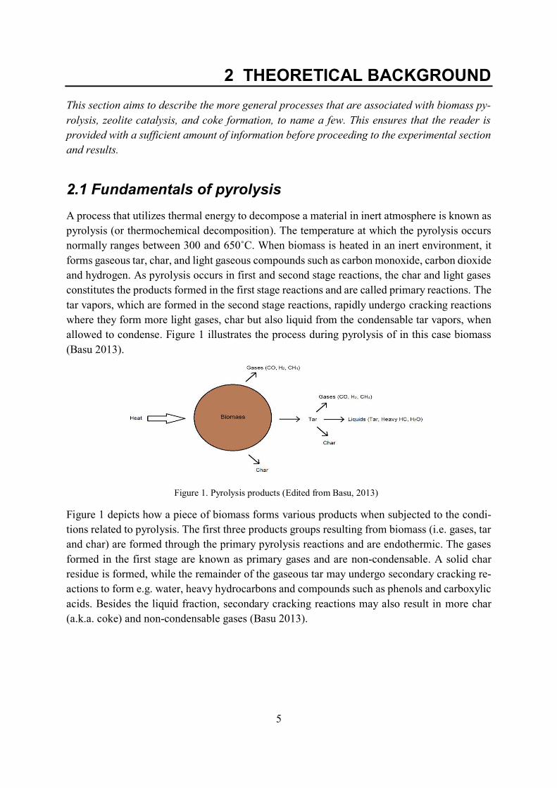
allowed to condense. Figure 1 illustrates the process during pyrolysis of in this case biomass
(Basu 2013).
Figure 1 depicts how a piece of biomass forms various products when subjected to the condi-
tions related to pyrolysis. The first three products groups resulting from biomass (i.e. gases, tar
and char) are formed through the primary pyrolysis reactions and are endothermic. The gases
formed in the first stage are known as primary gases and are non-condensable. A solid char
residue is formed, while the remainder of the gaseous tar may undergo secondary cracking re-
actions to form e.g. water, heavy hydrocarbons and compounds such as phenols and carboxylic
acids. Besides the liquid fraction, secondary cracking reactions may also result in more char
(a.k.a. coke) and non-condensable gases (Basu 2013).
Figure 1. Pyrolysis products (Edited from Basu, 2013)
6
Depending on the choice of pyrolysis conditions, it is possible to increase the selectivity toward
certain pyrolysis products. These conditions include for example pyrolysis temperature and va-
por residence time in the pyrolyzer. For example, when the aim is to produce as much char as
possible, it is preferable to decrease the temperature while increasing the residence time. How-
ever, when bio-oil is the desired product, it is more favorable to use moderate temperatures,
short residence time, and fast cooling of the vapors. This latter case is known as fast pyrolysis,
where the temperature is kept at around 500˚C and the vapor residence time is no longer than 2
seconds. By reducing the residence time and increase the heating rate of biomass, the decom-
position will be less prominent, resulting in more liquid gain. It is approximated that 75 percent
bio-oil can be achieved from dried biomass using fast pyrolysis at 500˚C and about one second residence time. To optimize the fast pyrolysis, it is important that the char formed is quickly
taken off, as it acts as a non-desirable cracking “catalyst” (Bridgwater 2012). Since biomass is
a poor heat conductor, it is also important to consider the sizing of the biomass particle itself.
It is preferred to use pieces of biomass which has been sized to about 2-6 mm (Bridgwater 2012)
(Basu 2013).
As mentioned before, the bio-oil is not suitable for direct use, in e.g. automobiles, due to the
high oxygen and water content in the oil. It is approximated that over 400 oxygen-containing
chemicals may exist simultaneously in the bio-oil. The high number and concentration of oxy-
gen compounds combined highlights the importance of deoxygenation (Serrano-Ruiz and
Dumesic 2012). Some of these compounds include aldehydes such as hydroxyacetaldehyde,
ketones in the form of 1-hydroxy-propan-2-one, and acids such as acetic acid (Aho et al. 2013).
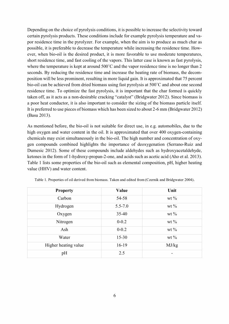
Table 1 lists some properties of the bio-oil such as elemental composition, pH, higher heating
value (HHV) and water content.
Table 1. Properties of oil derived from biomass. Taken and edited from (Czernik and Bridgwater 2004).
Property Value Unit
Carbon 54-58 wt %
Hydrogen 5.5-7.0 wt %
Oxygen 35-40 wt %
Nitrogen 0-0.2 wt %
Ash 0-0.2 wt %
Water 15-30 wt %
Higher heating value 16-19 MJ/kg
pH 2.5 -
7
To give some comparable data between bio-oil and crude oil, the oxygen content in the average
crude oil is around one percent (Klimisch et al. 1997) while the higher heating value lies be-
tween 42-44 MJ/kg and has a carbon content of 89 percent (World Nuclear Association 2016).
As Table 1 demonstrates, the low pH of the bio-oil together with high moisture content make
the oil more corrosive. This may cause corrosion in e.g. the storage tank of bio-oil. The combi-
nation of water and acids found in the bio-oil is not only responsible for making the oil more
corrosive, the water also reduces the heating value of the oil (together with the oxygen content)
which is not desirable. The bio-oil is also known to have a high viscosity due to the high oxygen
content, where the higher viscosity suppresses the oil’s lubrication ability (Czernik and Bridg-
water 2004).
A well-established process to perform pyrolysis is to utilize a fluidized bed reactor, for example
a bubbling fluidized bed reactor. The basic principle behind this technology is to incorporate a
bed material, which could be sand, and allowing hot gas such as N2 to pass through and heat up
the sand. The right amount of gas flow rate will exert just enough force on the sand to overcome
the gravity and keep the sand particles fluidized. The biomass, which have been sized into small
pieces (around 2-6 mm) will be brought into contact with the hot sand, thus initiating the py-
rolysis process (Basu 2013). Sand is often chosen as a fluidizing medium due to several reasons.
Mainly, it is inexpensive, it can tolerate temperatures above 1000˚C, and it shows good heat transfer properties. (Ramakers et al. 2004) (Johari and Rozainee 2007).
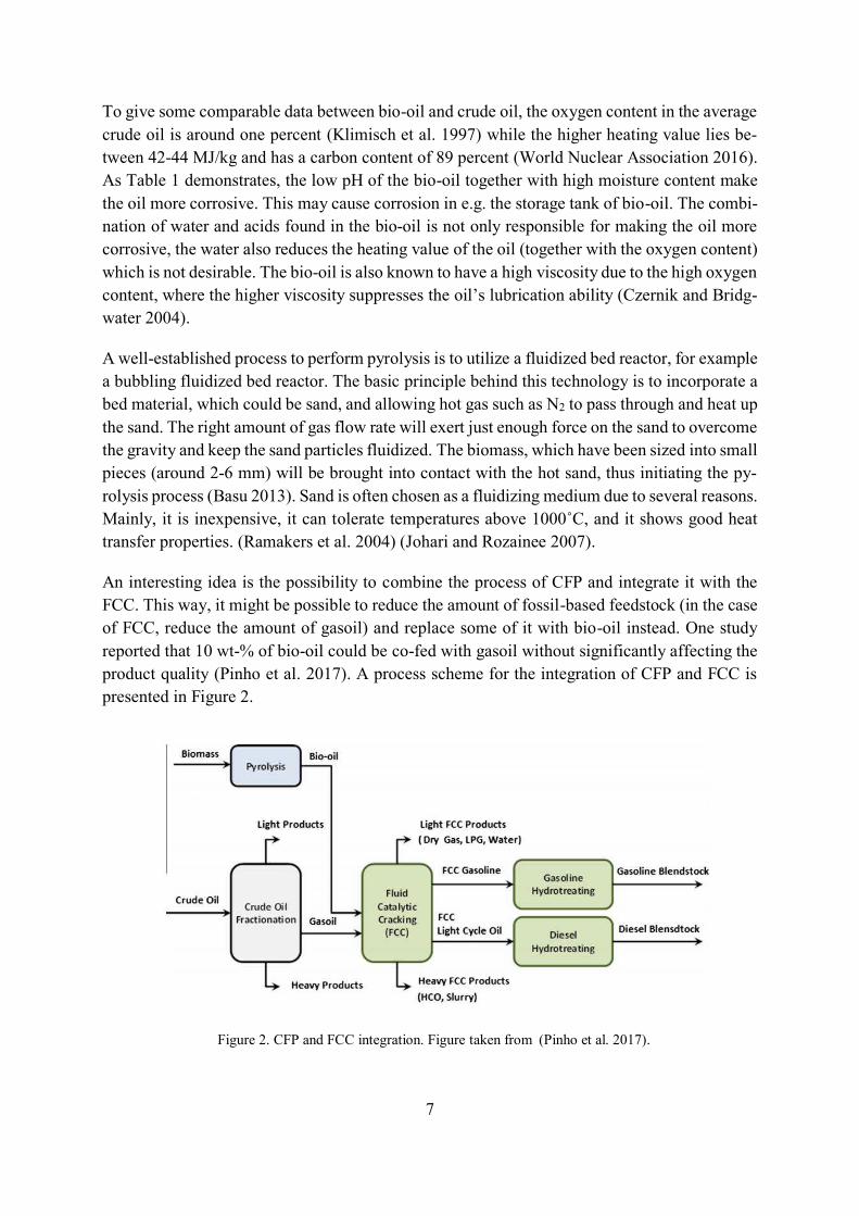
An interesting idea is the possibility to combine the process of CFP and integrate it with the
FCC. This way, it might be possible to reduce the amount of fossil-based feedstock (in the case
of FCC, reduce the amount of gasoil) and replace some of it with bio-oil instead. One study
reported that 10 wt-% of bio-oil could be co-fed with gasoil without significantly affecting the
product quality (Pinho et al. 2017). A process scheme for the integration of CFP and FCC is
presented in Figure 2.
Figure 2. CFP and FCC integration. Figure taken from (Pinho et al. 2017).
8
In Figure 2, the bio-oil is fed together with the gasoil and cracked to produce e.g. LCO. By
further improving the process integration of CFP and FCC, it might be possible to increase the
amount of bio-oil that could be utilized and thus making the FCC-process more environmentally
clean.
2.2 Fluid Catalytic Cracking (FCC)
Fluid Catalytic Cracking (FCC) is commonly found in the petroleum industry and is a highly
attractive process to produce valuable products such as gasoline, LCO, and olefins from heavier
material such as gas oils, via cracking reactions of heavy oil. Since it was first introduced com-
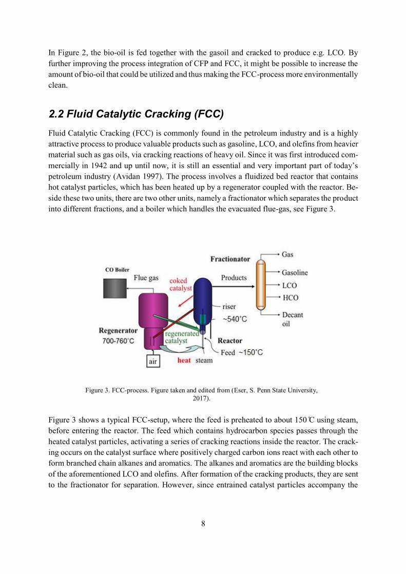
mercially in 1942 and up until now, it is still an essential and very important part of today’s petroleum industry (Avidan 1997). The process involves a fluidized bed reactor that contains
hot catalyst particles, which has been heated up by a regenerator coupled with the reactor. Be-
side these two units, there are two other units, namely a fractionator which separates the product
into different fractions, and a boiler which handles the evacuated flue-gas, see Figure 3.
Figure 3 shows a typical FCC-setup, where the feed is preheated to about 150 ̊C using steam,
before entering the reactor. The feed which contains hydrocarbon species passes through the
heated catalyst particles, activating a series of cracking reactions inside the reactor. The crack-
ing occurs on the catalyst surface where positively charged carbon ions react with each other to
form branched chain alkanes and aromatics. The alkanes and aromatics are the building blocks
of the aforementioned LCO and olefins. After formation of the cracking products, they are sent
to the fractionator for separation. However, since entrained catalyst particles accompany the
Figure 3. FCC-process. Figure taken and edited from (Eser, S. Penn State University,
2017).
9
product feed, a treatment step using cyclones are included to remove these particles before the
fractionator.
After some time, the cracking reactions will induce coke formation on the catalytic material,
which require removal by combustion using high-temperature air. The coke that is burned in
the regenerator releases heat, making this setup excellent for utilizing this heat in order to pre-
heat the catalyst material and to ensure enough heat for supporting the cracking (which is en-
dothermal) (Eser, S. 2017). It is important to mention that a steam stripping section is normally
used before sending the coked catalyst to the regenerator. The reason for this being that the
catalyst adsorbs certain hydrocarbons that are richer in hydrogen than ordinary coke. The risk
associated with higher hydrogen in the adsorbed molecules is water formation inside the regen-
erator, which together with elevated temperatures could cause irreversible damage on the cata-
lyst framework (Sadeghbeigi 2012). Fluid catalytic cracking has been successively enhanced
since it was first introduced in early 1940s. One example involves the introduction of zeolite
catalysts in the FCC-unit, namely Y-zeolites. The reason why zeolites turned out to be so suc-
cessful in FCC was due to their ability to enhance gasoline production by 50 percent. Appar-
ently, the zeolite is capable of improving cracking while at the same time not increasing the
coke formation drastically (known as coking selectivity). In modern day FCC-units, it is more
common to use a mixture of catalysts to achieve special properties in the product. For example,
Y-zeolites are supplemented with ZSM-5 in order to increase octane number. The catalyst size
usually varies between 20-150 μm with densities ranging from 1200-1700 kg/m3 (Avidan
1997).
2.3 Zeolites as catalysts
Zeolites are highly attractive catalysts in several industrial applications and serve usefulness in
a variety of fields such as fluid catalytic cracking. Zeolites are naturally abundant and are usu-
ally located in environments with high pH, for example near volcanos. Zeolites are referred to
as molecular sieves due to their ability to separate various molecules based on their size and
structure. Today, zeolites are synthetically manufactured and modified according to the appli-
cation of interest (Wang et al. 2017).
2.3.1 Properties of zeolites
A key feature responsible for the separation efficiency of zeolites is connected to its highly
porous structure that creates a large surface area. This allows various molecular species to dif-
fuse and become separated (Wang et al. 2017). The structural framework is comprised of tetra-
hedral silica and aluminum atoms joined together by charged oxygen atoms that form bonding
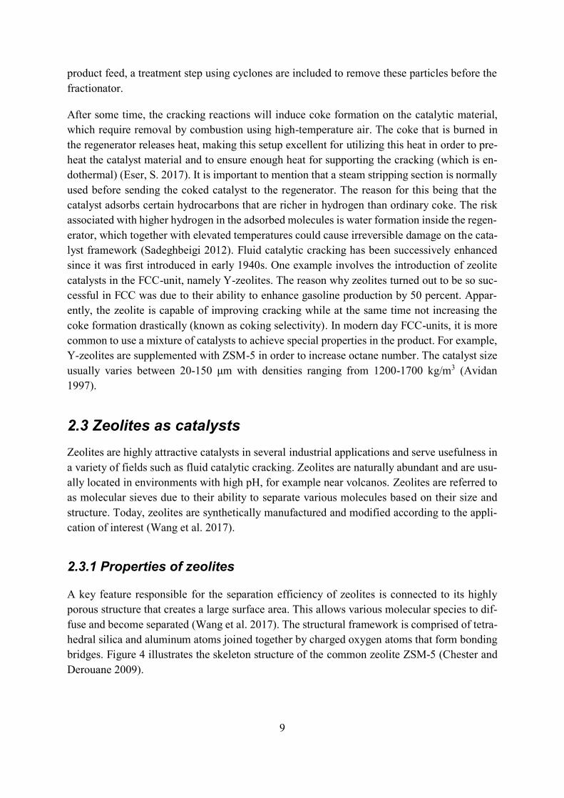
bridges. Figure 4 illustrates the skeleton structure of the common zeolite ZSM-5 (Chester and
Derouane 2009).
10
The structure displayed in Figure 4 represents the MFI-type zeolite, also known as ZSM-5, and
consists of 10-membered rings with pore diameters around 0.5 nm that forms a three-dimen-
sional internal structure. The size of the pores and channels in the zeolite acts as a limitation
towards the diffusion and adsorption of larger molecular compounds, which is a key factor for
understanding coke formation (Chester and Derouane 2009). This exclusion of larger com-
pounds entering the zeolite pores is something that is known as shape selectivity. Basically, the
theory of shape selectivity asserts that all reactions take place inside the catalysts microporous
structure (Guisnet 2007). Another vital property of the catalyst to take into consideration is the
ratio between silica and aluminum (SiO2/Al2O3). The main reason being its correlation to ther-
mal stability, where a higher Si/Al-ratio is associated with greater resistance to hydrothermal
damage. Last but not least, what determine the effectiveness of zeolites depend on its acidic
properties (Chester and Derouane 2009). These acid properties are a consequence of Brønsted
and Lewis sites, also called active sites, inside the micropores of the catalyst. The Brønsted sites
originates from the interaction between silica and aluminum in the zeolite structure with hy-
droxide (Si-OH-Al) (Damjanović and Auroux 2009). Although high Si/Al-ratio increases the
thermal stability of the zeolite, it seems to decrease its acidity. This indicates that there is a need
for balancing this ratio, to achieve a sufficiently good thermal stability and catalyst activity
(Coman and Parvulescu 2013 p.4). Due to the acidity and shape selectivity of the ZSM-5, it
serves as a great catalyst for cracking and deoxygenation. These properties are highly attractive
when considering biomass pyrolysis to produce bio-oil. However, it is assumed that the acidity
of a catalyst is also responsible the rapid coke formation (Iliopoulou et al. 2012).
Besides having acid sites, transition metals could also be incorporated in the micropores, thus
creating a bifunctional catalyst. Examples of such metals could be Pt, Ni, Fe, and Ga. It is
suggested that bifunctional zeolites containing Pt are less prone to catalyst deactivation by coke
formation (Guisnet 2007). Hence, there seems to be advantageous to utilize metal-doping on
catalysts to minimize coke formation. Reducing the coke amount could also have the benefit of
Figure 4. Structure of MFI (ZSM-5) zeolites. Picture from (In-
ternational Zeolite Association, 2017).
11
reducing the demand on catalyst regeneration by increasing the lifetime of a catalyst before
being deactivated.
2.3.2 Choice of Catalyst
Due to the highly porous structure of zeolites, which provides a large surface area for reactions
to occur, it is a highly preferred catalyst. There exists numerous types of zeolites to consider
for biomass pyrolysis is applications. In fluid catalytic cracking of fossil crude, the problem
with oxygenates are not as severe compared to catalytic fast pyrolysis of biomass. Therefore, a
key property of the zeolite of reforming pyrolytic vapors needs to be a good deoxygenation
capacity. Also, besides its deoxygenation capability, its ability to form the valuable MAHs
BTEX are also preferred. This is because some MAHs such as xylene are important in industrial
applications and can be e.g. mixed in fuel blends (Mullen and Boateng 2015). The ability to
form MAHs are assumed to be met with pleasing results using the ZSM-5. ZSM-5 possesses
certain qualities such as shape selectivity due to its internal microporous structure, and high
acidity due to Brønsted- and Lewis acid sites. The shape selectivity is believed to prevent larger
molecules to enter the catalyst and block the microporous channels. However, shape selectivity
also has the effect of trapping molecules that has reacted into larger molecules inside the pores.
This can eventually lead to coke formation and thereby blocking pores and thereby active sites.
The high acidity is responsible for the increased activity of the zeolite, which improves the
conversion efficiency of oxygenated compounds (Wang et al. 2017). HZSM-5 is considered to
be superior to other types of zeolites when the aim is aromatic hydrocarbon production. Ac-
cording to a study, CFP of maple wood yielded the highest amount of aromatics on HZSM-5
when compared to other types of zeolites such as the protonated from of mordenite, and Y-
zeolite. It was also superior to the catalysts silicalite and silica-alumina (Liu et al. 2014).
Certain features of zeolites are highly important for its catalytic efficiency and activity, and
therefore, it is recommended that these properties are examined before use. Two of these prop-
erties are crucial to determine, namely the surface area and the acidity.
2.4 Coke composition and its formation
As mentioned, biomass pyrolysis is a promising method for producing bio-oil that can be cata-
lytically upgraded. However, along with the valuable liquid fraction, there are also reactions
occurring at the surface and inside the catalyst which are not desirable. These reactions form
coke (a carbonaceous material) and thereby deactivate the catalyst over time. The coke that
builds up at different parts of the catalyst eventually leads to pore blocking of its microporous
structure and acid sites (Cerqueira et al. 2008). The chemical composition of coke formed dur-
ing pyrolysis of biomass varies depending on reaction conditions such as temperature but also
the type of catalyst used and the composition of the feedstock. The catalyst plays an important
role since zeolite catalysts come in many different shapes, sizes, pore structures and acidities.
12
2.4.1 Coking of catalysts during FCC
When dealing with the coke composition and its reaction pathway, it is usually interesting to
consider low- and high-temperature coke. At low temperatures (below 200˚C) the coke formed is mostly comprised of condensation products, and is highly reliant on the reactants involved.
Aliphatic hydrocarbons dominate the content of coke during low-temperature operation. What
is important to note is that the products formed during the low-temperature treatment do not
contain PAHs. However, when the temperature increases (>350 ˚C), the composition of the coke changes and is dominated by PAHs. In this latter case, the formation of PAHs is not de-
pendent on the reactants as much as in the low-temperature stage, it is now dependent mostly
on the structural properties of the catalyst, such as pore size. However, condensation reactions
do also occur in the high-temperature stage (Guisnet and Magnoux 2001) (Shao et al. 2017)
Coke is often divided into two different fractions, namely soluble- and insoluble coke. The
insoluble coke is often very difficult to analyze in detail due to its reluctance to be dissolved in
solvents. The inability to be dissolved in solvents, most commonly DCM, is where the term
“insoluble” stems from. Vice versa, the term “soluble” refers to the coke ability to be dissolved in solvents, again more commonly in DCM. The insoluble fraction consists of very large struc-
tures that comprise it. Due to its inability to be dissolved, the insoluble part of the coke is there-
fore often restricted to structural analysis, where one of these includes TEM-analysis. It has
been proven through this technique (along with other morphological techniques) that the insol-
uble coke on ZSM-5 catalysts resembles the structure of coronene, which is pre-graphitic. The
soluble coke, which is dissolved easily in DCM, is normally not as bulky as the insoluble dito,
because it mostly forms inside the small micropores of the ZSM-5 zeolite, restricting the
polymerization into larger aromatics. Compounds that can be found in the soluble coke are
various methyl benzenic species, pyrenes, and anthracenes (Guisnet and Magnoux 2001)
(Cerqueira et al. 2008). To understand the origin of the coke formed on catalysts used in fluid
catalytic cracking, a useful reaction scheme is illustrated in Figure 5, using n-heptane as a crack-
ing model compound.
13
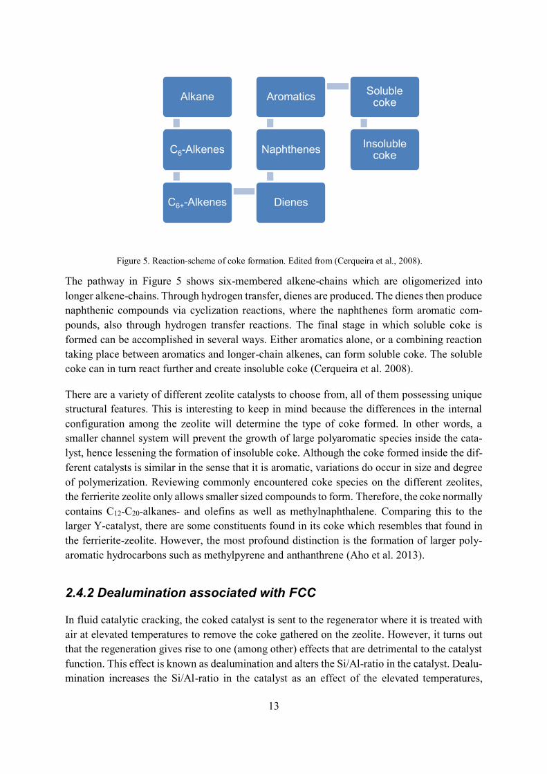
The pathway in Figure 5 shows six-membered alkene-chains which are oligomerized into
longer alkene-chains. Through hydrogen transfer, dienes are produced. The dienes then produce
naphthenic compounds via cyclization reactions, where the naphthenes form aromatic com-
pounds, also through hydrogen transfer reactions. The final stage in which soluble coke is
formed can be accomplished in several ways. Either aromatics alone, or a combining reaction
taking place between aromatics and longer-chain alkenes, can form soluble coke. The soluble
coke can in turn react further and create insoluble coke (Cerqueira et al. 2008).
There are a variety of different zeolite catalysts to choose from, all of them possessing unique
structural features. This is interesting to keep in mind because the differences in the internal
configuration among the zeolite will determine the type of coke formed. In other words, a
smaller channel system will prevent the growth of large polyaromatic species inside the cata-
lyst, hence lessening the formation of insoluble coke. Although the coke formed inside the dif-
ferent catalysts is similar in the sense that it is aromatic, variations do occur in size and degree
of polymerization. Reviewing commonly encountered coke species on the different zeolites,
the ferrierite zeolite only allows smaller sized compounds to form. Therefore, the coke normally
contains C12-C20-alkanes- and olefins as well as methylnaphthalene. Comparing this to the
larger Y-catalyst, there are some constituents found in its coke which resembles that found in
the ferrierite-zeolite. However, the most profound distinction is the formation of larger poly-
aromatic hydrocarbons such as methylpyrene and anthanthrene (Aho et al. 2013).
2.4.2 Dealumination associated with FCC
In fluid catalytic cracking, the coked catalyst is sent to the regenerator where it is treated with
air at elevated temperatures to remove the coke gathered on the zeolite. However, it turns out
that the regeneration gives rise to one (among other) effects that are detrimental to the catalyst
function. This effect is known as dealumination and alters the Si/Al-ratio in the catalyst. Dealu-
mination increases the Si/Al-ratio in the catalyst as an effect of the elevated temperatures,
Alkane
C6-Alkenes
C6+-Alkenes Dienes
Naphthenes
AromaticsSoluble
coke
Insoluble coke
Figure 5. Reaction-scheme of coke formation. Edited from (Cerqueira et al., 2008).
14
something that is promoted by increased vapor pressure of steam. This phenomenon starts to
become more evident when the temperature reaches 450˚C. Thus, it is advised to not to exceed
temperatures above 400˚C, to suppress dealumination as much as possible (Liu et al. 2014).
The dealumination mainly occurs in the regeneration step, where temperatures often meet the
requirement to initiate dealumination. Compared to the coking of zeolites, which was consid-
ered as reversible damage, dealumination is irreversible. Therefore, this irreversible deactiva-
tion is something that needs to be evaluated when performing fluid catalytic cracking (Müller
et al. 2000). The disturbing fact about dealumination is associated with the detrimental effects
it has on the acid site density of the catalyst, which includes Brønsted- and Lewis acid sites. It
is observed that Lewis acid sites endure most damage during more harsh environments in the
dealumination process, such as higher temperatures. The Brønsted sites, however, suffer more
during milder conditions (Liu et al. 2014). The consequence of a higher Si/Al-ratio due to dealu-
mination is therefore a decrease of the acidity of the zeolite, which leads to a reduced catalyst
activity. One study conducted by Gusev et al. concluded that the number of Brønsted- and
Lewis active sites were reduced by 90 and 80 % respectively, when exposed to hydrothermal
processing just over 800˚C (Gusev et al. 2015). Besides dealumination, another irreversible
damage on zeolites can be caused by localized hot-spots in the regenerator-reactor (Liu et al.
2014). These hot-spots could deactivate the catalyst by destroying the support material of the
catalyst (Satyanarayana et al. 2016).
2.4.3 Effects of aluminum content on the formation of aromatics
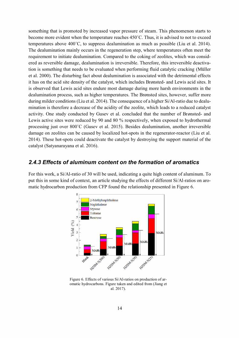
For this work, a Si/Al-ratio of 30 will be used, indicating a quite high content of aluminum. To
put this in some kind of context, an article studying the effects of different Si/Al-ratios on aro-
matic hydrocarbon production from CFP found the relationship presented in Figure 6.
Figure 6. Effects of various Si/Al-ratios on production of ar-
omatic hydrocarbons. Figure taken and edited from (Jiang et
al. 2017).
15
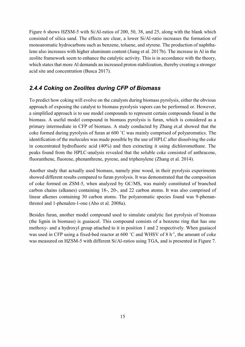
Figure 6 shows HZSM-5 with Si/Al-ratios of 200, 50, 38, and 25, along with the blank which
consisted of silica sand. The effects are clear, a lower Si/Al-ratio increases the formation of
monoaromatic hydrocarbons such as benzene, toluene, and styrene. The production of naphtha-
lene also increases with higher aluminum content (Jiang et al. 2017b). The increase in Al in the
zeolite framework seem to enhance the catalytic activity. This is in accordance with the theory,
which states that more Al demands an increased proton stabilization, thereby creating a stronger
acid site and concentration (Busca 2017).
2.4.4 Coking on Zeolites during CFP of Biomass
To predict how coking will evolve on the catalysts during biomass pyrolysis, either the obvious
approach of exposing the catalyst to biomass pyrolysis vapors can be performed or. However,
a simplified approach is to use model compounds to represent certain compounds found in the
biomass. A useful model compound in biomass pyrolysis is furan, which is considered as a
primary intermediate in CFP of biomass. A study conducted by Zhang et.al showed that the
coke formed during pyrolysis of furan at 600 ˚C was mainly comprised of polyaromatics. The
identification of the molecules was made possible by the use of HPLC after dissolving the coke
in concentrated hydrofluoric acid (40%) and then extracting it using dichloromethane. The
peaks found from the HPLC-analysis revealed that the soluble coke consisted of anthracene,
fluoranthene, fluorene, phenanthrene, pyrene, and triphenylene (Zhang et al. 2014).
Another study that actually used biomass, namely pine wood, in their pyrolysis experiments
showed different results compared to furan pyrolysis. It was demonstrated that the composition
of coke formed on ZSM-5, when analyzed by GC/MS, was mainly constituted of branched
carbon chains (alkanes) containing 18-, 20-, and 22 carbon atoms. It was also comprised of
linear alkenes containing 30 carbon atoms. The polyaromatic species found was 9-phenan-
threnol and 1-phenalen-1-one (Aho et al. 2008a).
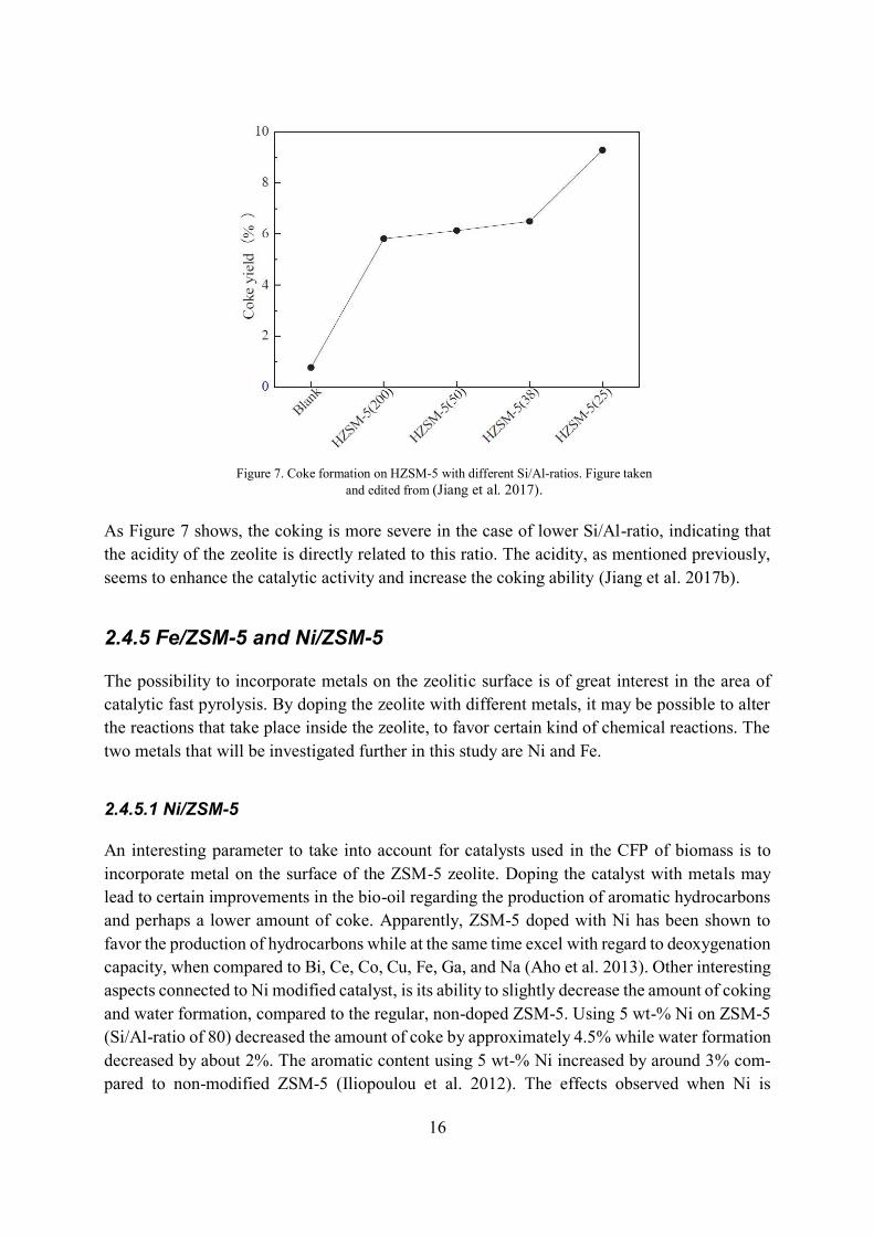
Besides furan, another model compound used to simulate catalytic fast pyrolysis of biomass
(the lignin in biomass) is guaiacol. This compound consists of a benzene ring that has one
methoxy- and a hydroxyl group attached to it in position 1 and 2 respectively. When guaiacol
was used in CFP using a fixed-bed reactor at 600 ˚C and WHSV of 8 h-1, the amount of coke
was measured on HZSM-5 with different Si/Al-ratios using TGA, and is presented in Figure 7.
16
As Figure 7 shows, the coking is more severe in the case of lower Si/Al-ratio, indicating that
the acidity of the zeolite is directly related to this ratio. The acidity, as mentioned previously,
seems to enhance the catalytic activity and increase the coking ability (Jiang et al. 2017b).
2.4.5 Fe/ZSM-5 and Ni/ZSM-5
The possibility to incorporate metals on the zeolitic surface is of great interest in the area of
catalytic fast pyrolysis. By doping the zeolite with different metals, it may be possible to alter
the reactions that take place inside the zeolite, to favor certain kind of chemical reactions. The
two metals that will be investigated further in this study are Ni and Fe.
2.4.5.1 Ni/ZSM-5
An interesting parameter to take into account for catalysts used in the CFP of biomass is to
incorporate metal on the surface of the ZSM-5 zeolite. Doping the catalyst with metals may
lead to certain improvements in the bio-oil regarding the production of aromatic hydrocarbons
and perhaps a lower amount of coke. Apparently, ZSM-5 doped with Ni has been shown to
favor the production of hydrocarbons while at the same time excel with regard to deoxygenation
capacity, when compared to Bi, Ce, Co, Cu, Fe, Ga, and Na (Aho et al. 2013). Other interesting
aspects connected to Ni modified catalyst, is its ability to slightly decrease the amount of coking
and water formation, compared to the regular, non-doped ZSM-5. Using 5 wt-% Ni on ZSM-5
(Si/Al-ratio of 80) decreased the amount of coke by approximately 4.5% while water formation
decreased by about 2%. The aromatic content using 5 wt-% Ni increased by around 3% com-
pared to non-modified ZSM-5 (Iliopoulou et al. 2012). The effects observed when Ni is
Figure 7. Coke formation on HZSM-5 with different Si/Al-ratios. Figure taken
and edited from (Jiang et al. 2017).
17
introduced are believed to be associated with the change in acidity relative to unmodified ZSM-
5. Table 2 lists some properties of these catalysts that have been put forward by Iliopoulou et.al.
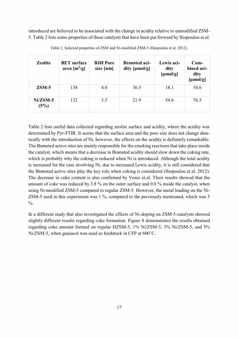
Table 2. Selected properties of ZSM and Ni-modified ZSM-5 (Iliopoulou et al. 2012).
Zeolite BET surface
area [m2/g]
BJH Pore
size [nm]
Brønsted aci-
dity [μmol/g]
Lewis aci-
dity
[μmol/g]
Com-
bined aci-
dity
[μmol/g] ZSM-5 138 4.0 36.5 18.1 54.6
Ni/ZSM-5
(5%)
132 3.5 21.9 54.6 76.5
Table 2 lists useful data collected regarding zeolite surface and acidity, where the acidity was
determined by Pyr-FTIR. It seems that the surface area and the pore size does not change dras-
tically with the introduction of Ni, however, the effects on the acidity is definitely remarkable.
The Brønsted active sites are mainly responsible for the cracking reactions that take place inside
the catalyst, which means that a decrease in Brønsted acidity should slow down the coking rate,
which is probably why the coking is reduced when Ni is introduced. Although the total acidity
is increased for the case involving Ni, due to increased Lewis acidity, it is still considered that
the Brønsted active sites play the key role when coking is considered (Iliopoulou et al. 2012).
The decrease in coke content is also confirmed by Veses et.al. Their results showed that the
amount of coke was reduced by 3.8 % on the outer surface and 0.8 % inside the catalyst, when
using Ni-modified ZSM-5 compared to regular ZSM-5. However, the metal loading on the Ni-
ZSM-5 used in this experiment was 1 %, compared to the previously mentioned, which was 5
%.
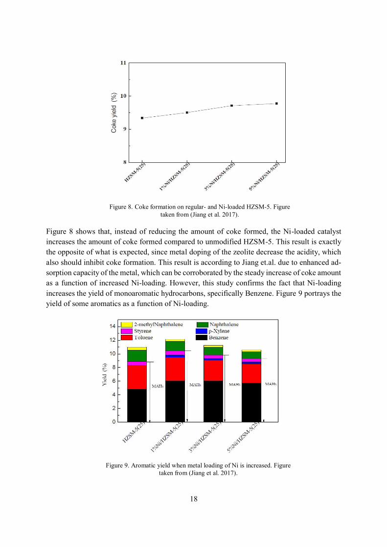
In a different study that also investigated the effects of Ni-doping on ZSM-5-catalysts showed
slightly different results regarding coke formation. Figure 8 demonstrates the results obtained
regarding coke amount formed on regular HZSM-5, 1% Ni/ZSM-5, 3% Ni/ZSM-5, and 5%
Ni/ZSM-5, when guaiacol was used as feedstock in CFP at 600˚C.
18
Figure 8 shows that, instead of reducing the amount of coke formed, the Ni-loaded catalyst
increases the amount of coke formed compared to unmodified HZSM-5. This result is exactly
the opposite of what is expected, since metal doping of the zeolite decrease the acidity, which
also should inhibit coke formation. This result is according to Jiang et.al. due to enhanced ad-
sorption capacity of the metal, which can be corroborated by the steady increase of coke amount
as a function of increased Ni-loading. However, this study confirms the fact that Ni-loading
increases the yield of monoaromatic hydrocarbons, specifically Benzene. Figure 9 portrays the
yield of some aromatics as a function of Ni-loading.
Figure 8. Coke formation on regular- and Ni-loaded HZSM-5. Figure
taken from (Jiang et al. 2017).
Figure 9. Aromatic yield when metal loading of Ni is increased. Figure
taken from (Jiang et al. 2017).
19
As is shown in Figure 9, the production of MAHs such as benzene and p-xylene can be in-
creased when introducing Ni to ZSM-5. At the same time, PAHs such as naphthalene and 2-
methylnaphthalene decrease with Ni introduction, indicating that coking may be suppressed as
PAHs constitute a large part of the coke. However, the effects of increased Ni amount on ZSM-
5 seem to reduce the yield of toluene found in the bio-oil (Jiang et al. 2017b).
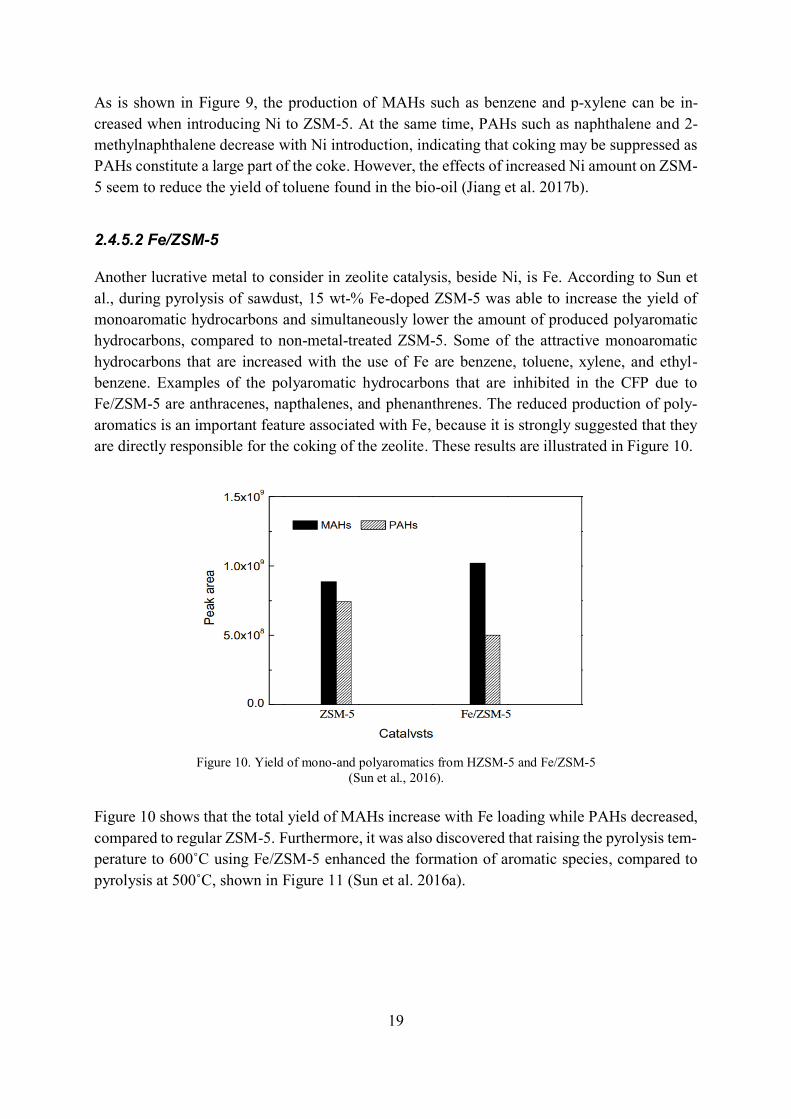
2.4.5.2 Fe/ZSM-5
Another lucrative metal to consider in zeolite catalysis, beside Ni, is Fe. According to Sun et
al., during pyrolysis of sawdust, 15 wt-% Fe-doped ZSM-5 was able to increase the yield of
monoaromatic hydrocarbons and simultaneously lower the amount of produced polyaromatic
hydrocarbons, compared to non-metal-treated ZSM-5. Some of the attractive monoaromatic
hydrocarbons that are increased with the use of Fe are benzene, toluene, xylene, and ethyl-
benzene. Examples of the polyaromatic hydrocarbons that are inhibited in the CFP due to
Fe/ZSM-5 are anthracenes, napthalenes, and phenanthrenes. The reduced production of poly-
aromatics is an important feature associated with Fe, because it is strongly suggested that they
are directly responsible for the coking of the zeolite. These results are illustrated in Figure 10.
Figure 10 shows that the total yield of MAHs increase with Fe loading while PAHs decreased,
compared to regular ZSM-5. Furthermore, it was also discovered that raising the pyrolysis tem-
perature to 600˚C using Fe/ZSM-5 enhanced the formation of aromatic species, compared to
pyrolysis at 500˚C, shown in Figure 11 (Sun et al. 2016a).
Figure 10. Yield of mono-and polyaromatics from HZSM-5 and Fe/ZSM-5
(Sun et al., 2016).
20
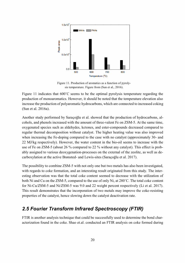
Figure 11 indicates that 600˚C seems to be the optimal pyrolysis temperature regarding the
production of monoaromatics. However, it should be noted that the temperature elevation also
increase the production of polyaromatic hydrocarbons, which are connected to increased coking
(Sun et al. 2016a).
Another study performed by Saraçoğlu et al. showed that the production of hydrocarbons, al-
cohols, and phenols increased with the amount of three-valent Fe on ZSM-5. At the same time,
oxygenated species such as aldehydes, ketones, and ester-compounds decreased compared to
regular thermal decomposition without catalyst. The higher heating value was also improved
when increasing the Fe-doping compared to the case with no catalyst (approximately 30- and
22 MJ/kg respectively). However, the water content in the bio-oil seems to increase with the
use of Fe on ZSM-5 (about 26 % compared to 22 % without any catalyst). This effect is prob-
ably assigned to various deoxygenation-processes on the external of the zeolite, as well as de-
carboxylation at the active Brønsted- and Lewis-sites (Saraçoğlu et al. 2017).
The possibility to combine ZSM-5 with not only one but two metals has also been investigated,
with regards to coke formation, and an interesting result originated from this study. The inter-
esting observation was that the total coke content seemed to decrease with the utilization of
both Ni and Cu on the ZSM-5, compared to the use of only Ni, at 280˚C. The total coke content
for Ni-Cu/ZSM-5 and Ni/ZSM-5 was 9.0 and 22 weight percent respectively (Li et al. 2017).
This result demonstrates that the incorporation of two metals may improve the coke-resisting
properties of the catalyst, hence slowing down the catalyst deactivation rate.
2.5 Fourier Transform Infrared Spectroscopy (FTIR)
FTIR is another analysis technique that could be successfully used to determine the bond char-
acterization found in the coke. Shao et.al. conducted an FTIR analysis on coke formed during
Figure 11. Production of aromatics as a function of pyroly-
sis temperature. Figure from (Sun et al., 2016).
21
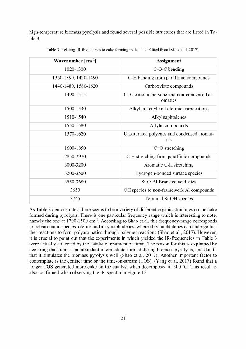
high-temperature biomass pyrolysis and found several possible structures that are listed in Ta-
ble 3.
Table 3. Relating IR-frequencies to coke forming molecules. Edited from (Shao et al. 2017).
Wavenumber [cm-1] Assignment
1020-1300 C-O-C bending
1360-1390, 1420-1490 C-H bending from paraffinic compounds
1440-1480, 1580-1620 Carboxylate compounds
1490-1515 C=C cationic polyene and non-condensed ar-
omatics
1500-1530 Alkyl, alkenyl and olefinic carbocations
1510-1540 Alkylnaphtalenes
1550-1580 Allylic compounds
1570-1620 Unsaturated polyenes and condensed aromat-
ics
1600-1850 C=O stretching
2850-2970 C-H stretching from paraffinic compounds
3000-3200 Aromatic C-H stretching
3200-3500 Hydrogen-bonded surface species
3550-3680 Si-O-Al Brønsted acid sites
3650 OH species to non-framework Al compounds
3745 Terminal Si-OH species
As Table 3 demonstrates, there seems to be a variety of different organic structures on the coke
formed during pyrolysis. There is one particular frequency range which is interesting to note,
namely the one at 1700-1500 cm-1. According to Shao et.al, this frequency-range corresponds
to polyaromatic species, olefins and alkylnaphtalenes, where alkylnaphtalenes can undergo fur-
ther reactions to form polyaromatics through polymer reactions (Shao et al., 2017). However,
it is crucial to point out that the experiments in which yielded the IR-frequencies in Table 3
were actually collected by the catalytic treatment of furan. The reason for this is explained by
declaring that furan is an abundant intermediate formed during biomass pyrolysis, and due to
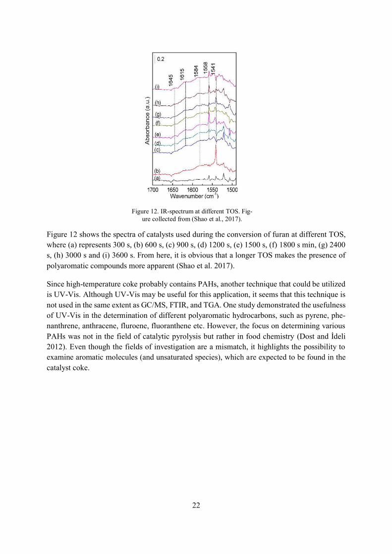
that it simulates the biomass pyrolysis well (Shao et al. 2017). Another important factor to
contemplate is the contact time or the time-on-stream (TOS). (Yang et al. 2017) found that a
longer TOS generated more coke on the catalyst when decomposed at 500 ˚C. This result is also confirmed when observing the IR-spectra in Figure 12.
22
Figure 12 shows the spectra of catalysts used during the conversion of furan at different TOS,
where (a) represents 300 s, (b) 600 s, (c) 900 s, (d) 1200 s, (e) 1500 s, (f) 1800 s min, (g) 2400
s, (h) 3000 s and (i) 3600 s. From here, it is obvious that a longer TOS makes the presence of
polyaromatic compounds more apparent (Shao et al. 2017).
Since high-temperature coke probably contains PAHs, another technique that could be utilized
is UV-Vis. Although UV-Vis may be useful for this application, it seems that this technique is
not used in the same extent as GC/MS, FTIR, and TGA. One study demonstrated the usefulness
of UV-Vis in the determination of different polyaromatic hydrocarbons, such as pyrene, phe-
nanthrene, anthracene, fluroene, fluoranthene etc. However, the focus on determining various
PAHs was not in the field of catalytic pyrolysis but rather in food chemistry (Dost and İdeli 2012). Even though the fields of investigation are a mismatch, it highlights the possibility to
examine aromatic molecules (and unsaturated species), which are expected to be found in the
catalyst coke.
Figure 12. IR-spectrum at different TOS. Fig-
ure collected from (Shao et al., 2017).
23
2.5.1 Working principle of FTIR
Infrared spectroscopy is a useful technique to incorporate when the aim is to identify functional
groups in chemical compounds. Today, FTIR is considered to be one of the most efficient ways
of performing IR-analyses, mainly due to its simple handling and low time-consuming nature.
The idea behind this technique has been known for more than a hundred years, however, it was
not until the end of the 1960s that FTIR became commercialized. The fundamental idea behind
FTIR is to compute Fourier transformation on interference patterns (interferograms) created in
the interferometer, to turn it into a spectrum (Subramanian and Rodriguez-Saona 2009). The
different parts in the FTIR consists of source that emits light at the infrared frequency range.
The light passes by the interferometer, where an interference pattern is created from light beams
that interacts with each other. The interacted beams is then introduced to the sample, which
absorbs certain frequencies of the light and sends it to a detector that examines the interference
pattern from the sample. The background is also subjected to light beams to enable the possi-
bility to remove those peaks from the sample peaks in the final step, where the software per-
forms the Fourier analysis to generate a spectrum (Mohamed et al. 2017).
When conducting FTIR-analysis, there are different sample handling techniques that can be
adopted. The choice of this technique highly depends on the type of sample that is to be ana-
lyzed. A popular sample handling technique is the ATR-FTIR, which is suitable for examining
otherwise difficult substances such as rubber, plastics, and various strong absorbing materials.
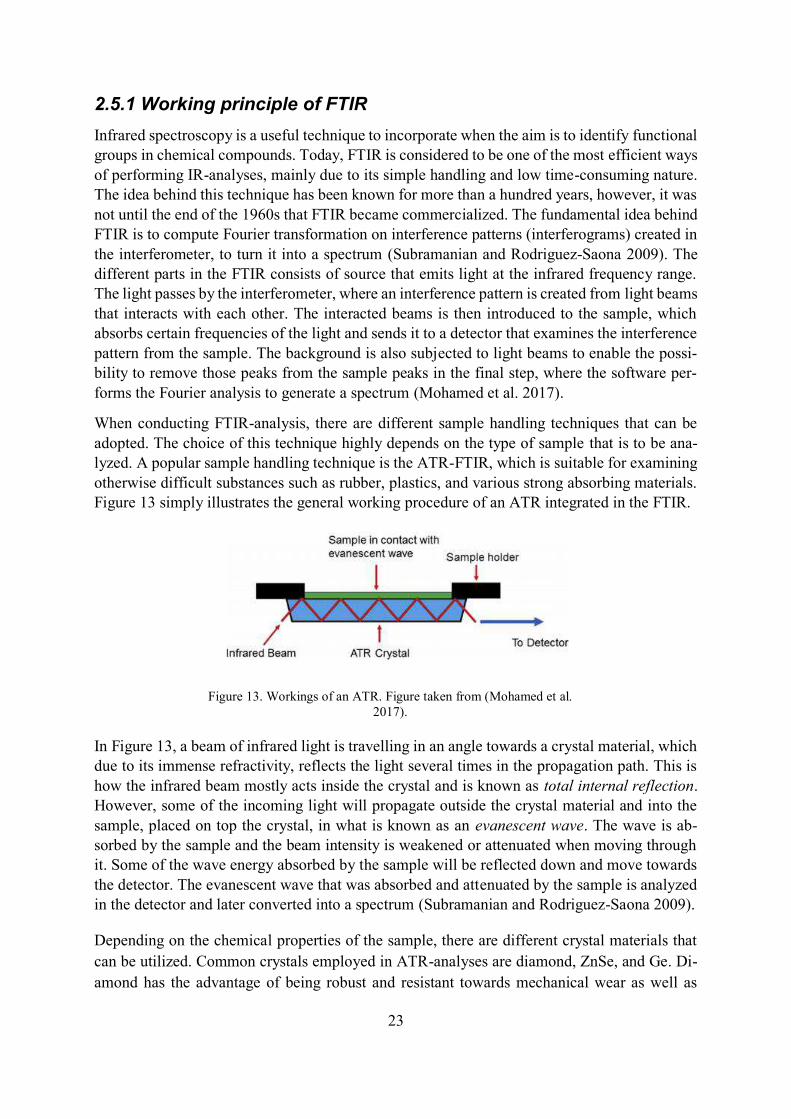
Figure 13 simply illustrates the general working procedure of an ATR integrated in the FTIR.
In Figure 13, a beam of infrared light is travelling in an angle towards a crystal material, which
due to its immense refractivity, reflects the light several times in the propagation path. This is
how the infrared beam mostly acts inside the crystal and is known as total internal reflection.
However, some of the incoming light will propagate outside the crystal material and into the
sample, placed on top the crystal, in what is known as an evanescent wave. The wave is ab-
sorbed by the sample and the beam intensity is weakened or attenuated when moving through
it. Some of the wave energy absorbed by the sample will be reflected down and move towards
the detector. The evanescent wave that was absorbed and attenuated by the sample is analyzed
in the detector and later converted into a spectrum (Subramanian and Rodriguez-Saona 2009).
Depending on the chemical properties of the sample, there are different crystal materials that
can be utilized. Common crystals employed in ATR-analyses are diamond, ZnSe, and Ge. Di-
amond has the advantage of being robust and resistant towards mechanical wear as well as
Figure 13. Workings of an ATR. Figure taken from (Mohamed et al.
2017).
24
tough chemicals such as strong acids and bases. Its depth of penetration is 1.66 µm, which is
the same as zinc selenide. The depth of penetration depends on the wavelength and angle of the
incident light, as well as the refractive index of the crystal. Certain types of samples that easily
absorbs infrared light can be more effectively analyzed using a crystal with a higher refractive
index. In these cases, Ge is the more suitable choice compared to diamond and zinc selenide
(PerkinElmer 2004). Overall, the benefits of using ATR is clearly due the simplicity of analyz-
ing samples, the effortless cleaning of the crystal, and the rapid analysis process. Another cru-
cial benefit that makes this technique desirable is the vast number of different samples that can
be analyzed by choosing the appropriate crystal (Subramanian and Rodriguez-Saona 2009).
2.6 Thermogravimetric Analysis (TGA)
Thermogravimetric analysis (TGA) is an analysis technique used to examine the characteristics
of the coke when exposed to different temperatures. In this technique, the coked catalyst is
heated with a chosen temperature gradient. This provides valuable information about the coke
content, since it is possible to evaluate how much mass-% of coke is oxidized at a certain tem-
perature range. It also reveals information about the required regeneration temperature of the
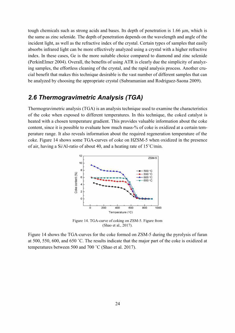
coke. Figure 14 shows some TGA-curves of coke on HZSM-5 when oxidized in the presence
of air, having a Si/Al-ratio of about 40, and a heating rate of 15˚C/min.
Figure 14 shows the TGA-curves for the coke formed on ZSM-5 during the pyrolysis of furan
at 500, 550, 600, and 650 ˚C. The results indicate that the major part of the coke is oxidized at
temperatures between 500 and 700 ˚C (Shao et al. 2017).
Figure 14. TGA-curve of coking on ZSM-5. Figure from
(Shao et al., 2017).
25
3 MATERIALS AND METHODS
In this section, the experimental procedures as well as the different analysis techniques utilized
in the thesis will be presented. The first part of the experimental phase is comprised of CFP of
biomass, using a mixture of pine and spruce saw dust. Four HZSM-5 catalysts were used during
the pyrolysis. Three of these previously had been doped with different metals, leaving one
which was not doped with any metal. This implies that all the catalysts had the same support
material. Pyrolysis of the saw dust mixture was conducted once for every different catalyst, and
after the completion of the pyrolysis, the bio-oil as well as the coked catalyst was collected.
This procedure was also previously performed, and the coked catalysts were then ready to be
examined by the chosen analyses techniques. This is where the experimental part of the thesis
work starts.
3.1 Choice of analyses techniques
The three analyses techniques chosen to examine the coked catalysts were GC/MS, FTIR, and
TGA. For the GC/MS and FTIR-analyses, the catalysts required further treatment in order to
separate the coke adsorbed on the catalyst surface. The GC/MS analysis provides information
about the different compounds that are present in the dissolved coke and the corresponding peak
areas. The FTIR analysis is a powerful tool that can effectively complement the GC/MS. The
information gathered from the FTIR reveals valuable information about the bond characteristics
found among the compounds in the dissolved coke. This can either corroborate with the results
completely or even detect traces of other compounds not detected in the GC/MS-analysis.
Lastly, the thermal behavior of both the insoluble and soluble coke will be analyzed using TGA.
By steadily increasing the combustion temperature and observe how the mass changes over
time, the amount coke can be determined.
3.2 The Biomass Pyrolysis Process
The pyrolysis of biomass was performed at 500˚C in a pilot scale fixed bed reactor, which
consisted of a 60 cm long steel tube reactor with an inner diameter of 5 cm. The biomass was
introduced to the heated part of the reactor when the goal temperature was reached. Prior to
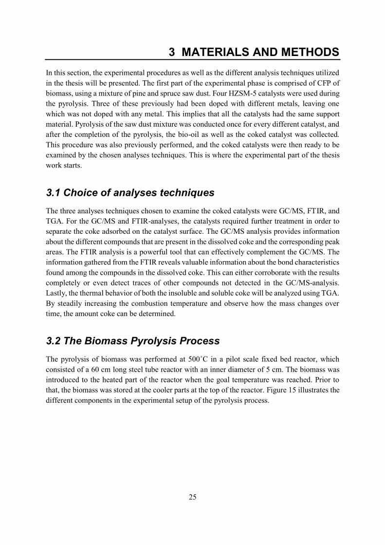
that, the biomass was stored at the cooler parts at the top of the reactor. Figure 15 illustrates the
different components in the experimental setup of the pyrolysis process.
26
As Figure 15 demonstrates, the heated nitrogen gas flows down from the top and meets the
vapors formed from the decomposition of the biomass. The vapors are carried down with the
nitrogen and through the catalyst bed, where catalytic cracking reactions occurs. The catalyti-
cally upgraded vapors can finally be collected in an external condenser situated below the re-
actor. The condenser consists of a series of washing bottles placed in a cooling bath, that is
filled with a mixture of isopropanol and water and kept at −17˚C constantly, where the vapors
are condensed.
3.3 Catalyst preparation and properties
The incorporation of metals on the zeolite structure was accomplished, followed by a drying
step at 105˚C and then calcined. The treatment was performed to attain a concentration of 5 wt-
% of Fe in one case, and the same amount of Ni in the other case. When combining Fe and Ni
on the same catalyst, the amount of metal was higher, with a concentration of 5 wt-% of each
metal on the zeolite. The surface area was determined by an instrumental method called the
BET-method, using N2. The surface area of the zeolites is affected by introducing Fe, Ni, and
both Fe and Ni on the zeolites. The surface area is decreased for metal-doped catalysts, espe-
cially in the case when two metals are incorporated. The acidity can be analyzed using temper-
ature-programmed-desorption with ammonia (TPD-NH3). However, this was not performed for
the particular zeolites used for this thesis. An elemental analysis of the zeolites were performed
by an external laboratory, utilizing ICP/MS. The Si/Al-ratio for the catalysts used in the exper-
iments had a value of 30.
3.4 Separation of coke and zeolite
The first step before the GC/MS and the FTIR-analyses could be performed on the coke was to
dissolve the zeolite framework, in order to separate the adsorbed coke from the catalyst. This
Figure 15. Experimental setup of pyrolysis reactor.
27
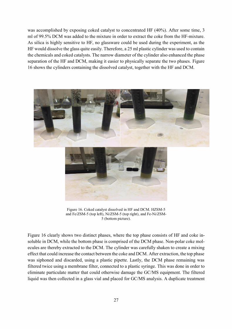
was accomplished by exposing coked catalyst to concentrated HF (40%). After some time, 3
ml of 99.5% DCM was added to the mixture in order to extract the coke from the HF-mixture.
As silica is highly sensitive to HF, no glassware could be used during the experiment, as the
HF would dissolve the glass quite easily. Therefore, a 25 ml plastic cylinder was used to contain
the chemicals and coked catalysts. The narrow diameter of the cylinder also enhanced the phase
separation of the HF and DCM, making it easier to physically separate the two phases. Figure
16 shows the cylinders containing the dissolved catalyst, together with the HF and DCM.
Figure 16 clearly shows two distinct phases, where the top phase consists of HF and coke in-
soluble in DCM, while the bottom phase is comprised of the DCM phase. Non-polar coke mol-
ecules are thereby extracted to the DCM. The cylinder was carefully shaken to create a mixing
effect that could increase the contact between the coke and DCM. After extraction, the top phase
was siphoned and discarded, using a plastic pipette. Lastly, the DCM phase remaining was
filtered twice using a membrane filter, connected to a plastic syringe. This was done in order to
eliminate particulate matter that could otherwise damage the GC/MS equipment. The filtered
liquid was then collected in a glass vial and placed for GC/MS analysis. A duplicate treatment
Figure 16. Coked catalyst dissolved in HF and DCM. HZSM-5
and Fe/ZSM-5 (top left), Ni/ZSM-5 (top right), and Fe-Ni/ZSM-
5 (bottom picture).
28
dissolution and extraction of coke from of each catalyst was performed. This was done in order
to enable two separate runs for the GC/MS analysis.
After the extraction was completed, a GC/MS analysis was initiated to analyze the composition
of soluble coke components. This method has been presented by many studies, one example
being where Aho et al. investigated the bio-oil derived from catalytic fast pyrolysis of pine (Aho
et al. 2008a). However, it should be mentioned that one study conducted by Magnoux et al.
showed that the soluble coke fraction constitutes only 30% of the total coke formed at 450˚C. The coke formed at this temperature consisted mostly of PAHs with three to five-membered
rings, while at 120˚C, the coke consisted mainly of unsaturated hydrocarbons with approxi-
mately C30-chains. This suggests that increasing the temperature in the pyrolysis process creates
more insoluble species, making temperature elevations in the pyrolysis a process which should
be performed with caution. Another important remark is that the coke constituents discovered
in this paper was performed on the Y-zeolite, which has larger pores than the ZSM-5. Therefore,
it is more probable that larger species will form inside the Y-zeolite (Magnoux et al. 1987).
3.5 GC/MS
The GC used was an Agilent 7890A, coupled with an Agilent MS 5975C, where a HP-5 capil-
lary column and He carrier gas was utilized. The oven was programmed to start at 40˚C and
was kept there for two minutes before ramping occurred to 140˚C at 10˚C/min. After reaching
140˚C, ramping immediately occurred to 315˚C at 3˚C/min, and was kept under isothermal
conditions at that temperature for 15 min. The He gas flow was maintained constant at 0.7
ml/min and the injection was performed at splitless conditions. A blank consisting of DCM was
used in between each sample run to track any impurities that could accumulate in the system.
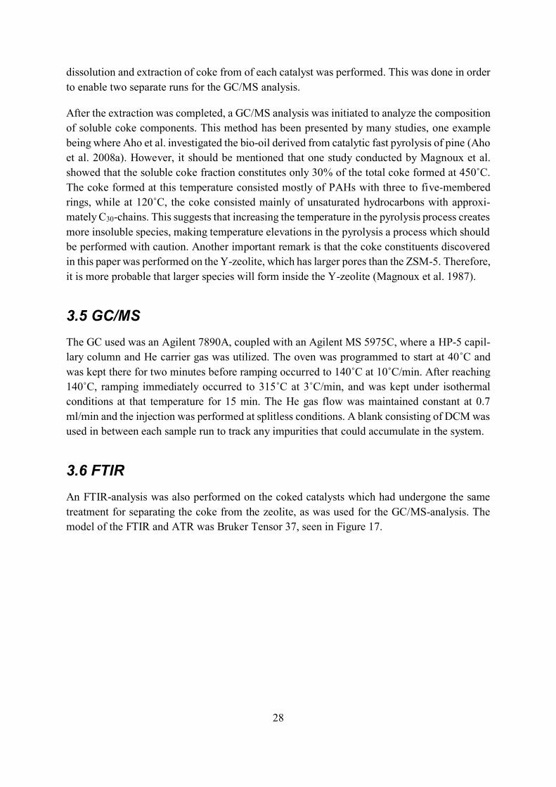
3.6 FTIR
An FTIR-analysis was also performed on the coked catalysts which had undergone the same
treatment for separating the coke from the zeolite, as was used for the GC/MS-analysis. The
model of the FTIR and ATR was Bruker Tensor 37, seen in Figure 17.
29
As can be seen in Figure 17, the ATR is located in the middle of the apparatus where there is a
disk on its center. On top of that disk, there is a small diamond crystal in which the liquid sample
was placed upon. The sample is normally pressed using the handle shown, to ensure a good
contact between the sample and the crystal. However, in this case that was not necessary since
the sample was in liquid form and not solid. Every catalyst was analyzed between the wave-
number range of 4000-400 cm-1, using 128 scans and a resolution of 4 cm-1. Before the analysis,
a background spectrum was collected to eliminate the absorption bands of moisture present in
the air.
As mentioned previously, the FTIR analysis also required the coke to be separated from the
zeolite structure using the same procedure as for the GC/MS analysis. However, due to the
toxicity of DCM and its fast evaporation capacity, it was not suitable to conduct the analysis in
an open environment without proper ventilation. This was not a problem for the GC/MS anal-
ysis since the DCM was stored in a sealed vial. The analysis required another approach to im-
prove the safety of the experiment. Therefore, the samples containing the coke dissolved in
DCM was completely evaporated in a fume box a day in advance, until only a solid residue
remained. The samples were then dissolved in acetone and placed immediately on the ATR-
crystal, allowing the acetone to completely evaporate before initiating the analysis. The reason
why the sample was dissolved in acetone was due to the fact that the amount of solid residue
was to scarce to perform a solid analysis. Acetone was also chosen due to its harmless proper-
ties, compared to DCM.
3.7 TGA
The TGA used was a Mettler Toledo TGA/DSC 1, equipped with an autosampler that enabled
the run of multiple samples simultaneously. The TGA was performed on the solid coked cata-
lyst, i.e. catalyst that did not undergo any pre-treatment as for the GC/MS and FTIR-analyses.
Duplicate runs were performed on each catalyst, including catalyst that was not coked, to obtain
a reference sample. An empty crucible was also placed in the TGA to function as a blank for
Figure 17. FTIR/ATR
30
buoyancy effect. The analysis was conducted in the temperature range of 50-850˚C, with a temperature gradient of 10˚C/min, and pure oxygen used as carrier gas. In order to remove
moisture in the samples, the TGA was programmed to maintain isothermal conditions at 110˚C for 20 minutes before proceeding with the temperature ramp. This was done to easily distin-
guish the weight loss connected to water in each TGA spectrum from the weight loss charac-
teristics of the hydrogen-carbon content. The coke content could then be calculated from the
TGA data, using equation (1) (Aho et al. 2008b).
1 82 00
50
5
8
100%C Ccoke
C
m mX
m
(1)
Xcoke denotes the relative amount of coke, while m120˚C and m850˚C represents the mass at 120˚C and 850˚C, respectively.
3.8 Delimitations
The work during this thesis focuses on the effects observed regarding coke formation when
introducing the transition metals Fe and Ni on HZSM-5, compared to non-doped HZSM-5, e.g.
coke composition and amount generated at fixed pyrolysis conditions. More specifically, to try
to deduce whether the inclusion of these metals could influence the amount- and type of coke
formed on the catalyst. One limitation in this case will be the number of metals chosen and the
corresponding concentrations. Although there are many interesting metals to consider, Fe, Ni,
and a combination of both will be the only investigated alongside regular HZSM-5. They were
chosen based on Ni being a well-studied dopant on HZSM-5, Fe being partly studied and indi-
cating a suppression of PAHs (i.e. potential reduction of coke formation). The interesting ques-
tion remained, whether the combination of the two metals would have a significant effect on
the coke composition and amount.
Another limitation in this work will be the exclusion of a detailed analysis on the insoluble coke
formed. To be more specific, due to the complexity of dissolving this fraction, a detailed chem-
ical analysis would be almost impossible, both from a chemical point of view and the limited
time frame. One can argue that structural analysis methods such as TEM could be suitable for
the insoluble coke. However, it is questionable whether such an analysis will yield information
about coke precursors for example. It has already been concluded that insoluble coke found on
the external of the zeolite is comprised of highly polyaromatic species, hence the insolubility
(Guisnet and Magnoux 2001). Therefore, the only analysis that will include the insoluble coke
is the TGA.
Regarding the soluble coke fraction, the combination of three different analysis techniques will
employed to guarantee the detection of MAHs and PAHs, as well as other unsaturated species
that may be found in the coke and the bio-oil. These techniques include the combination of
GC/MS, FTIR, and TGA. This setup of different analysis methods will hopefully detect all
species responsible for coke formation. Including FTIR may, for example, be useful if heavier

31
compounds are present and cannot be detected by GC/MS. The combination of techniques in-
creases the chances of not overlooking any molecular species that could be present, as well as
contributing to a more complete study.

32
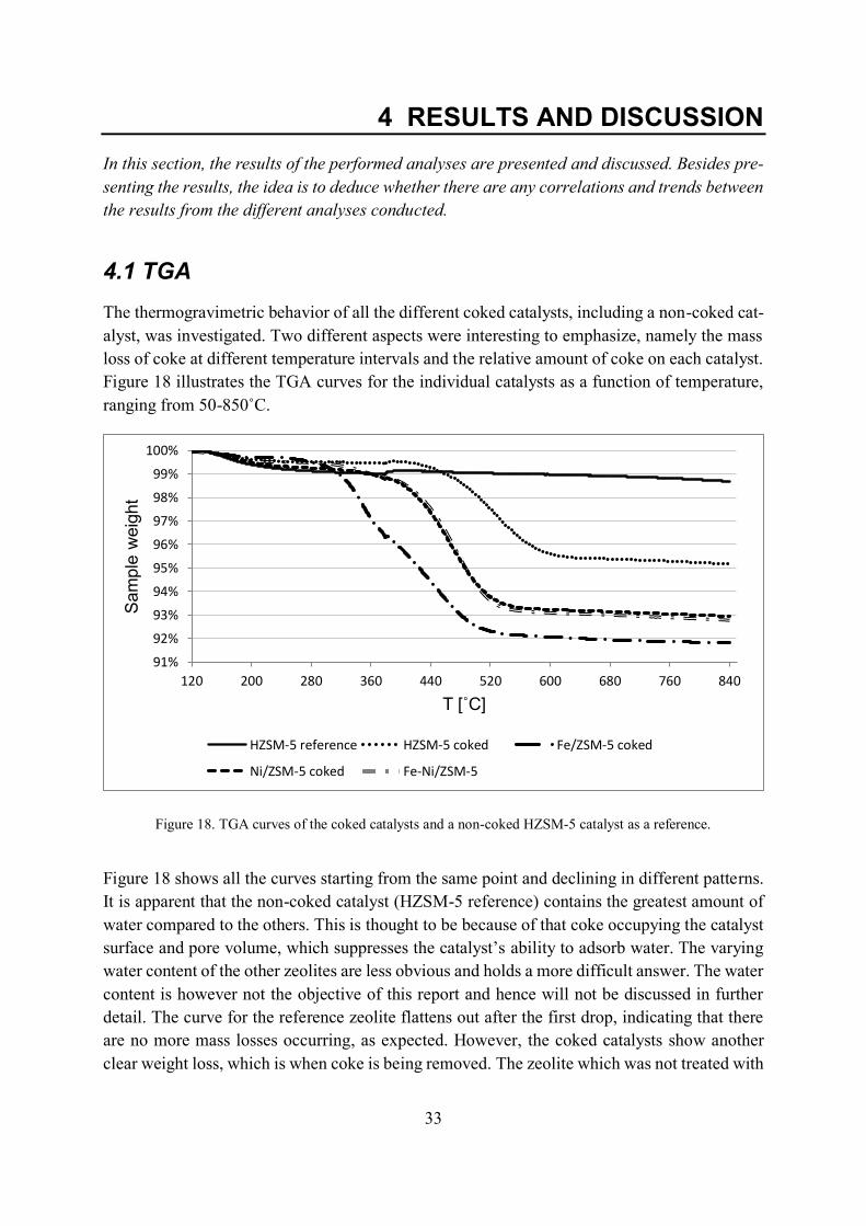
33
4 RESULTS AND DISCUSSION
In this section, the results of the performed analyses are presented and discussed. Besides pre-
senting the results, the idea is to deduce whether there are any correlations and trends between
the results from the different analyses conducted.
4.1 TGA
The thermogravimetric behavior of all the different coked catalysts, including a non-coked cat-
alyst, was investigated. Two different aspects were interesting to emphasize, namely the mass
loss of coke at different temperature intervals and the relative amount of coke on each catalyst.
Figure 18 illustrates the TGA curves for the individual catalysts as a function of temperature,
ranging from 50-850˚C.
Figure 18 shows all the curves starting from the same point and declining in different patterns.
It is apparent that the non-coked catalyst (HZSM-5 reference) contains the greatest amount of
water compared to the others. This is thought to be because of that coke occupying the catalyst
surface and pore volume, which suppresses the catalyst’s ability to adsorb water. The varying
water content of the other zeolites are less obvious and holds a more difficult answer. The water
content is however not the objective of this report and hence will not be discussed in further
detail. The curve for the reference zeolite flattens out after the first drop, indicating that there
are no more mass losses occurring, as expected. However, the coked catalysts show another
clear weight loss, which is when coke is being removed. The zeolite which was not treated with
91%
92%
93%
94%
95%
96%
97%
98%
99%
100%
120 200 280 360 440 520 600 680 760 840
Sam
ple
weig
ht
T [˚C]
HZSM-5 reference HZSM-5 coked Fe/ZSM-5 coked
Ni/ZSM-5 coked Fe-Ni/ZSM-5
Figure 18. TGA curves of the coked catalysts and a non-coked HZSM-5 catalyst as a reference.
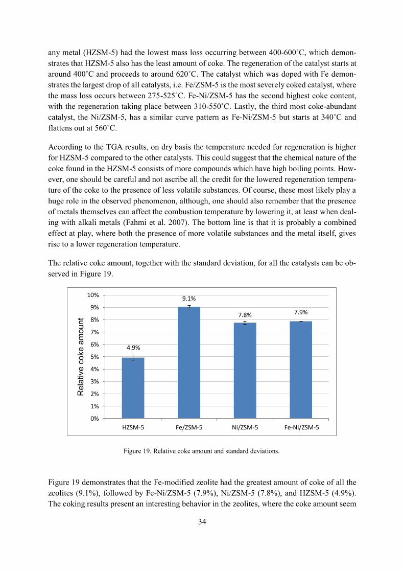
34
any metal (HZSM-5) had the lowest mass loss occurring between 400-600˚C, which demon-strates that HZSM-5 also has the least amount of coke. The regeneration of the catalyst starts at
around 400˚C and proceeds to around 620˚C. The catalyst which was doped with Fe demon-
strates the largest drop of all catalysts, i.e. Fe/ZSM-5 is the most severely coked catalyst, where
the mass loss occurs between 275-525˚C. Fe-Ni/ZSM-5 has the second highest coke content,
with the regeneration taking place between 310-550˚C. Lastly, the third most coke-abundant
catalyst, the Ni/ZSM-5, has a similar curve pattern as Fe-Ni/ZSM-5 but starts at 340˚C and
flattens out at 560˚C.
According to the TGA results, on dry basis the temperature needed for regeneration is higher
for HZSM-5 compared to the other catalysts. This could suggest that the chemical nature of the
coke found in the HZSM-5 consists of more compounds which have high boiling points. How-
ever, one should be careful and not ascribe all the credit for the lowered regeneration tempera-
ture of the coke to the presence of less volatile substances. Of course, these most likely play a
huge role in the observed phenomenon, although, one should also remember that the presence
of metals themselves can affect the combustion temperature by lowering it, at least when deal-
ing with alkali metals (Fahmi et al. 2007). The bottom line is that it is probably a combined
effect at play, where both the presence of more volatile substances and the metal itself, gives
rise to a lower regeneration temperature.
The relative coke amount, together with the standard deviation, for all the catalysts can be ob-
served in Figure 19.
Figure 19 demonstrates that the Fe-modified zeolite had the greatest amount of coke of all the
zeolites (9.1%), followed by Fe-Ni/ZSM-5 (7.9%), Ni/ZSM-5 (7.8%), and HZSM-5 (4.9%).
The coking results present an interesting behavior in the zeolites, where the coke amount seem
4.9%
9.1%
7.8% 7.9%
0%
1%
2%
3%
4%
5%
6%
7%
8%
9%
10%
HZSM-5 Fe/ZSM-5 Ni/ZSM-5 Fe-Ni/ZSM-5
Rela
tive c
oke a
mount
Figure 19. Relative coke amount and standard deviations.
35
to be dependent on the metal used. First, the literature discusses the influence of the acidity of
a zeolite, suggesting that the activity, and hence the coking ability of a zeolite, increases with
increasing acidity. This should naturally mean that the most acidic catalyst would be the most
severely coked catalyst. According to the literature, the acidity of HZSM-5 is greater compared
to Ni/ZSM-5. It also shows that when the total metal content increases, the acidity of the zeolite
decreases (Jiang et al. 2017a). However, even though the Ni/ZSM-5 is less acidic than HZSM-
5, it presents a greater amount of coke. Based on the acidity argument, this seems a bit surpris-
ing. On the other hand, both Ni and Fe are known to be more prone to coking, for example seen
in steam reforming processes. The increased formation of coke related to the higher concentra-
tion of Ni on the HZSM-5, is also evident when observing Figure 8. The increase in coke
amount clearly shows that the metal plays a tremendous role, and according to the literature, it
is most likely due to the enhancement of adsorption capacity of Ni (Jiang et al. 2017a). Another
study reported that Ni promote reactions such as hydrogen transfer and hydrogenation, which
could increase the formation of coke (Liu et al. 2014). The literature does not explicitly relate
the adsorption capacity of Fe and the increased formation of coke. One can assume that a similar
argument about the adsorption capacity can be ascribed to the Fe/ZSM-5 as well, however, this
is only speculative at this point.
Another interesting aspect that is revealed in Figure 19 is the decrease in coke formation in the
Fe-Ni/ZSM-5, compared to Fe/ZSM-5, and the slight increase compared to Ni/ZSM-5. Based
on the fact that both Ni and Fe favor formation of coke, it was expected that the combination
of these two would increase the coke amount an even larger extent. However, this turned out to
not be the case, instead the two metals slightly inhibit coke yield. This effect, when combining
Ni and Fe, is difficult to describe without conducting further research. Although, the effect is
clearly apparent, and it seems that Ni and Fe impair each other’s activity.
4.2 GC/MS
To better understand the results obtained in the TGA experiments, it is appropriate to link those
results to the findings in the GC/MS experiments. For example, it is interesting to relate if there
are any correlations between the compounds detected in the GC/MS analysis and the TGA
curves. If the catalysts display certain regeneration profiles compared to one another, are there
any significant differences in the chemistry of the coke? Obviously, it is more difficult to con-
nect the coke amount with the results in the GC/MS analysis. Nevertheless, by analyzing the
data from the GC/MS experiments properly, the results from the TGA could perhaps be better
understood. Firstly, the most abundant chemical compounds discovered in the coke for each
catalyst will be presented. Following that, the aromaticity and cyclization of the compounds
will discussed and lastly, the types of compounds will found in the different catalysts will also
be presented.
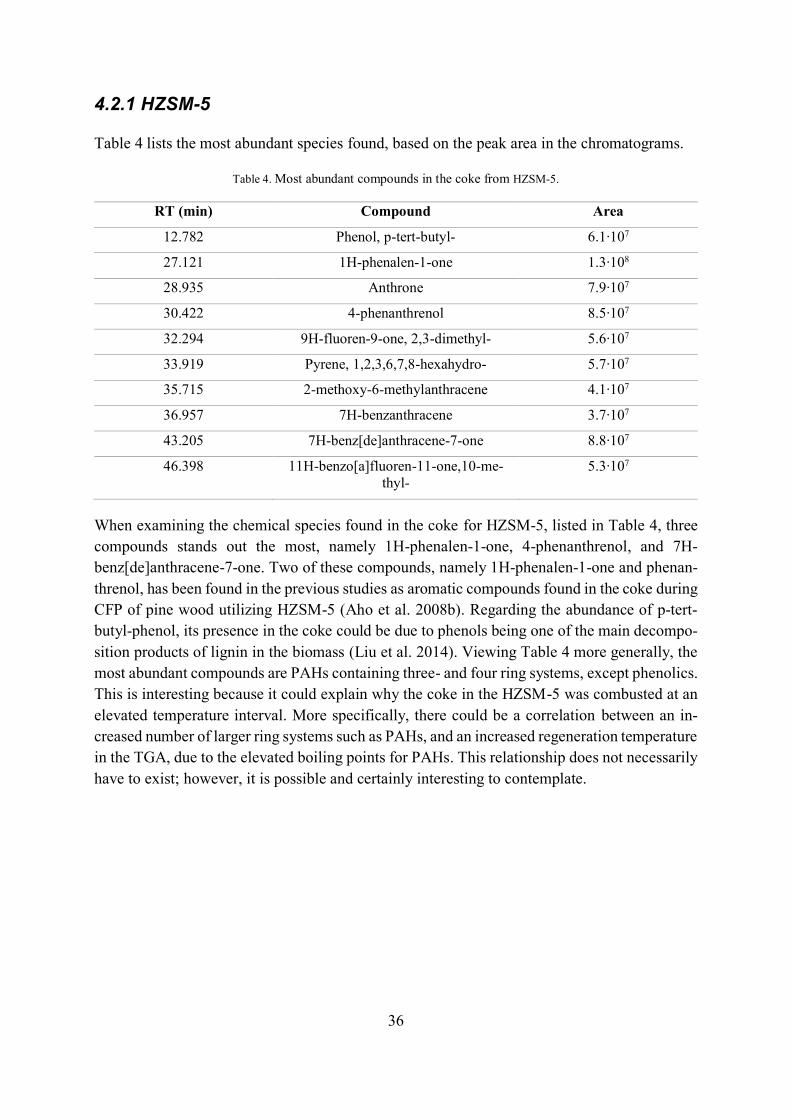
36
4.2.1 HZSM-5
Table 4 lists the most abundant species found, based on the peak area in the chromatograms.
Table 4. Most abundant compounds in the coke from HZSM-5.
RT (min) Compound Area
12.782 Phenol, p-tert-butyl- 6.1∙107
27.121 1H-phenalen-1-one 1.3∙108
28.935 Anthrone 7.9∙107
30.422 4-phenanthrenol 8.5∙107
32.294 9H-fluoren-9-one, 2,3-dimethyl- 5.6∙107
33.919 Pyrene, 1,2,3,6,7,8-hexahydro- 5.7∙107
35.715 2-methoxy-6-methylanthracene 4.1∙107
36.957 7H-benzanthracene 3.7∙107
43.205 7H-benz[de]anthracene-7-one 8.8∙107
46.398 11H-benzo[a]fluoren-11-one,10-me-
thyl-
5.3∙107
When examining the chemical species found in the coke for HZSM-5, listed in Table 4, three
compounds stands out the most, namely 1H-phenalen-1-one, 4-phenanthrenol, and 7H-
benz[de]anthracene-7-one. Two of these compounds, namely 1H-phenalen-1-one and phenan-
threnol, has been found in the previous studies as aromatic compounds found in the coke during
CFP of pine wood utilizing HZSM-5 (Aho et al. 2008b). Regarding the abundance of p-tert-
butyl-phenol, its presence in the coke could be due to phenols being one of the main decompo-
sition products of lignin in the biomass (Liu et al. 2014). Viewing Table 4 more generally, the
most abundant compounds are PAHs containing three- and four ring systems, except phenolics.
This is interesting because it could explain why the coke in the HZSM-5 was combusted at an
elevated temperature interval. More specifically, there could be a correlation between an in-
creased number of larger ring systems such as PAHs, and an increased regeneration temperature
in the TGA, due to the elevated boiling points for PAHs. This relationship does not necessarily
have to exist; however, it is possible and certainly interesting to contemplate.
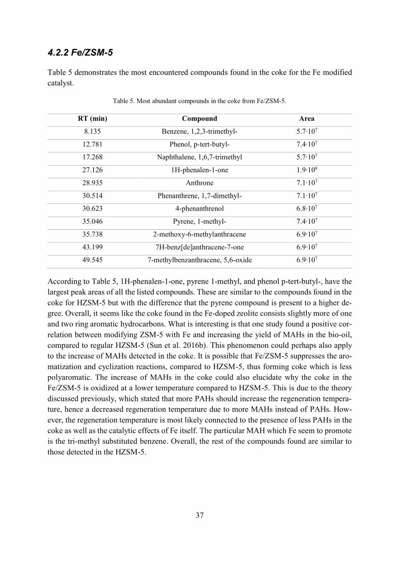
37
4.2.2 Fe/ZSM-5
Table 5 demonstrates the most encountered compounds found in the coke for the Fe modified
catalyst.
Table 5. Most abundant compounds in the coke from Fe/ZSM-5.
RT (min) Compound Area
8.135 Benzene, 1,2,3-trimethyl- 5.7∙107
12.781 Phenol, p-tert-butyl- 7.4∙107
17.268 Naphthalene, 1,6,7-trimethyl 5.7∙107
27.126 1H-phenalen-1-one 1.9∙108
28.935 Anthrone 7.1∙107
30.514 Phenanthrene, 1,7-dimethyl- 7.1∙107
30.623 4-phenanthrenol 6.8∙107
35.046 Pyrene, 1-methyl- 7.4∙107
35.738 2-methoxy-6-methylanthracene 6.9∙107
43.199 7H-benz[de]anthracene-7-one 6.9∙107
49.545 7-methylbenzanthracene, 5,6-oxide 6.9∙107
According to Table 5, 1H-phenalen-1-one, pyrene 1-methyl, and phenol p-tert-butyl-, have the
largest peak areas of all the listed compounds. These are similar to the compounds found in the
coke for HZSM-5 but with the difference that the pyrene compound is present to a higher de-
gree. Overall, it seems like the coke found in the Fe-doped zeolite consists slightly more of one
and two ring aromatic hydrocarbons. What is interesting is that one study found a positive cor-
relation between modifying ZSM-5 with Fe and increasing the yield of MAHs in the bio-oil,
compared to regular HZSM-5 (Sun et al. 2016b). This phenomenon could perhaps also apply
to the increase of MAHs detected in the coke. It is possible that Fe/ZSM-5 suppresses the aro-
matization and cyclization reactions, compared to HZSM-5, thus forming coke which is less
polyaromatic. The increase of MAHs in the coke could also elucidate why the coke in the
Fe/ZSM-5 is oxidized at a lower temperature compared to HZSM-5. This is due to the theory
discussed previously, which stated that more PAHs should increase the regeneration tempera-
ture, hence a decreased regeneration temperature due to more MAHs instead of PAHs. How-
ever, the regeneration temperature is most likely connected to the presence of less PAHs in the
coke as well as the catalytic effects of Fe itself. The particular MAH which Fe seem to promote
is the tri-methyl substituted benzene. Overall, the rest of the compounds found are similar to
those detected in the HZSM-5.
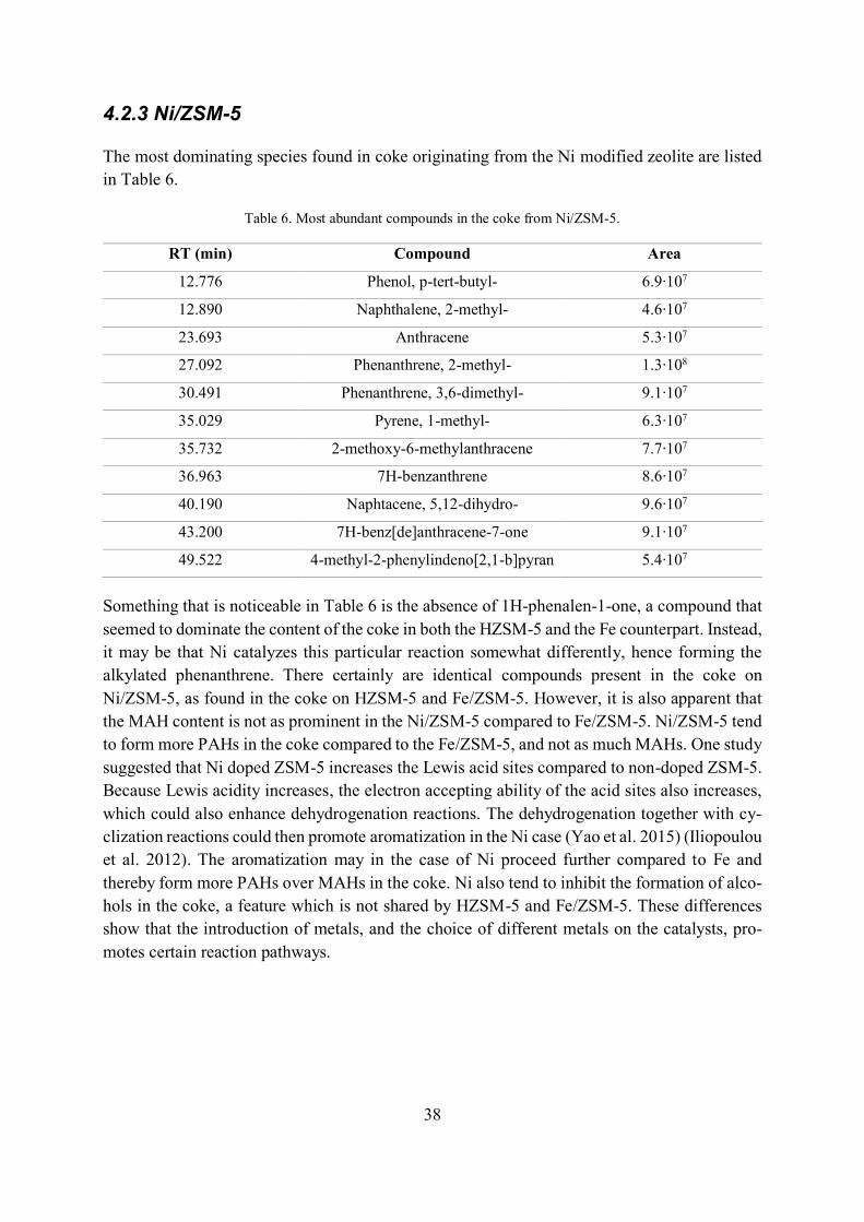
38
4.2.3 Ni/ZSM-5
The most dominating species found in coke originating from the Ni modified zeolite are listed
in Table 6.
Table 6. Most abundant compounds in the coke from Ni/ZSM-5.
RT (min) Compound Area
12.776 Phenol, p-tert-butyl- 6.9∙107
12.890 Naphthalene, 2-methyl- 4.6∙107
23.693 Anthracene 5.3∙107
27.092 Phenanthrene, 2-methyl- 1.3∙108
30.491 Phenanthrene, 3,6-dimethyl- 9.1∙107
35.029 Pyrene, 1-methyl- 6.3∙107
35.732 2-methoxy-6-methylanthracene 7.7∙107
36.963 7H-benzanthrene 8.6∙107
40.190 Naphtacene, 5,12-dihydro- 9.6∙107
43.200 7H-benz[de]anthracene-7-one 9.1∙107
49.522 4-methyl-2-phenylindeno[2,1-b]pyran 5.4∙107
Something that is noticeable in Table 6 is the absence of 1H-phenalen-1-one, a compound that
seemed to dominate the content of the coke in both the HZSM-5 and the Fe counterpart. Instead,
it may be that Ni catalyzes this particular reaction somewhat differently, hence forming the
alkylated phenanthrene. There certainly are identical compounds present in the coke on
Ni/ZSM-5, as found in the coke on HZSM-5 and Fe/ZSM-5. However, it is also apparent that
the MAH content is not as prominent in the Ni/ZSM-5 compared to Fe/ZSM-5. Ni/ZSM-5 tend
to form more PAHs in the coke compared to the Fe/ZSM-5, and not as much MAHs. One study
suggested that Ni doped ZSM-5 increases the Lewis acid sites compared to non-doped ZSM-5.
Because Lewis acidity increases, the electron accepting ability of the acid sites also increases,
which could also enhance dehydrogenation reactions. The dehydrogenation together with cy-
clization reactions could then promote aromatization in the Ni case (Yao et al. 2015) (Iliopoulou
et al. 2012). The aromatization may in the case of Ni proceed further compared to Fe and
thereby form more PAHs over MAHs in the coke. Ni also tend to inhibit the formation of alco-
hols in the coke, a feature which is not shared by HZSM-5 and Fe/ZSM-5. These differences
show that the introduction of metals, and the choice of different metals on the catalysts, pro-
motes certain reaction pathways.
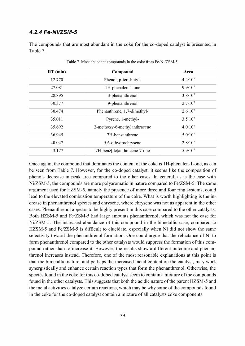
39
4.2.4 Fe-Ni/ZSM-5
The compounds that are most abundant in the coke for the co-doped catalyst is presented in
Table 7.
Table 7. Most abundant compounds in the coke from Fe-Ni/ZSM-5.
RT (min) Compound Area
12.770 Phenol, p-tert-butyl- 4.4∙107
27.081 1H-phenalen-1-one 9.9∙107
28.895 3-phenanthrenol 3.8∙107
30.377 9-phenanthrenol 2.7∙107
30.474 Phenanthrene, 1,7-dimethyl- 2.6∙107
35.011 Pyrene, 1-methyl- 3.5∙107
35.692 2-methoxy-6-methylanthracene 4.0∙107
36.945 7H-benzanthrene 5.0∙107
40.047 5,6-dihydrochrysene 2.8∙107
43.177 7H-benz[de]anthracene-7-one 5.9∙107
Once again, the compound that dominates the content of the coke is 1H-phenalen-1-one, as can
be seen from Table 7. However, for the co-doped catalyst, it seems like the composition of
phenols decrease in peak area compared to the other cases. In general, as is the case with
Ni/ZSM-5, the compounds are more polyaromatic in nature compared to Fe/ZSM-5. The same
argument used for HZSM-5, namely the presence of more three and four ring systems, could
lead to the elevated combustion temperature of the coke. What is worth highlighting is the in-
crease in phenanthrenol species and chrysene, where chrysene was not as apparent in the other
cases. Phenanthrenol appears to be highly present in this case compared to the other catalysts.
Both HZSM-5 and Fe/ZSM-5 had large amounts phenanthrenol, which was not the case for
Ni/ZSM-5. The increased abundance of this compound in the bimetallic case, compared to
HZSM-5 and Fe/ZSM-5 is difficult to elucidate, especially when Ni did not show the same
selectivity toward the phenanthrenol formation. One could argue that the reluctance of Ni to
form phenanthrenol compared to the other catalysts would suppress the formation of this com-
pound rather than to increase it. However, the results show a different outcome and phenan-
threnol increases instead. Therefore, one of the most reasonable explanations at this point is
that the bimetallic nature, and perhaps the increased metal content on the catalyst, may work
synergistically and enhance certain reaction types that form the phenanthrenol. Otherwise, the
species found in the coke for this co-doped catalyst seem to contain a mixture of the compounds
found in the other catalysts. This suggests that both the acidic nature of the parent HZSM-5 and
the metal activities catalyze certain reactions, which may be why some of the compounds found
in the coke for the co-doped catalyst contain a mixture of all catalysts coke components.
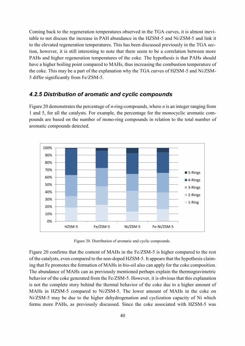
40
Coming back to the regeneration temperatures observed in the TGA curves, it is almost inevi-
table to not discuss the increase in PAH abundance in the HZSM-5 and Ni/ZSM-5 and link it
to the elevated regeneration temperatures. This has been discussed previously in the TGA sec-
tion, however, it is still interesting to note that there seem to be a correlation between more
PAHs and higher regeneration temperatures of the coke. The hypothesis is that PAHs should
have a higher boiling point compared to MAHs, thus increasing the combustion temperature of
the coke. This may be a part of the explanation why the TGA curves of HZSM-5 and Ni/ZSM-
5 differ significantly from Fe/ZSM-5.
4.2.5 Distribution of aromatic and cyclic compounds
Figure 20 demonstrates the percentage of n-ring-compounds, where n is an integer ranging from
1 and 5, for all the catalysts. For example, the percentage for the monocyclic aromatic com-
pounds are based on the number of mono-ring compounds in relation to the total number of
aromatic compounds detected.
Figure 20 confirms that the content of MAHs in the Fe/ZSM-5 is higher compared to the rest
of the catalysts, even compared to the non-doped HZSM-5. It appears that the hypothesis claim-
ing that Fe promotes the formation of MAHs in bio-oil also can apply for the coke composition.
The abundance of MAHs can as previously mentioned perhaps explain the thermogravimetric
behavior of the coke generated from the Fe/ZSM-5. However, it is obvious that this explanation
is not the complete story behind the thermal behavior of the coke due to a higher amount of
MAHs in HZSM-5 compared to Ni/ZSM-5. The lower amount of MAHs in the coke on
Ni/ZSM-5 may be due to the higher dehydrogenation and cyclization capacity of Ni which
forms more PAHs, as previously discussed. Since the coke associated with HZSM-5 was
0%
10%
20%
30%
40%
50%
60%
70%
80%
90%
100%
HZSM-5 Fe/ZSM-5 Ni/ZSM-5 Fe-Ni/ZSM-5
5-Rings
4-Rings
3-Rings
2-Rings
1-Ring
Figure 20. Distribution of aromatic and cyclic compounds.
41
combusted at a higher temperature than Ni/ZSM-5, this cannot be the one single determining
factor. Although, what is more common between the coke generated from HZSM-5, Ni/ZSM-
5, and Fe-Ni/ZSM-5, which oxidized at a higher temperature, is the amount of aromatic- and
cyclic compounds that contain four rings. Having a greater number of four-ring-systems in the
coke should increase the heating demand required for combustion. The largest number of four-
ring compounds appears to be most present in coke from HZSM-5, followed by Fe-Ni/ZSM-5
and Ni/ZSM-5. This order also seems to fit in with the temperature demand needed to combust
the coke, being highest for HZSM-5, followed by Fe-Ni/ZSM-5 and Ni/ZSM-5. Hence, there
seems to be a connection between the number of four-ring-compounds and elevated coke-oxi-
dation temperatures.
When it comes to explaining the increased coke amount found in Fe/ZSM-5, e.g. compared to
HZSM-5, it is almost impossible to draw any solid conclusions based on the GC/MS-analysis.
It is possible to observe differences between the GC spectra when comparing HZSM-5 and
Fe/ZSM-5. It turns out that Fe/ZSM-5 has larger peak areas than HZSM-5 at almost every lo-
cation in the GC-spectrum. This can be observed in the Appendix, where the spectra for HZSM-
5 and Fe/ZSM-5 have been overlaid to better observe these differences. The first important
remark is that the peak areas cannot be used directly to translate the peaks into concentrations
without proper calibration curves. Secondly, the increase in peak areas does not necessarily
have to be related to the increased coke amount observed in the TGA results. Equating the larger
peak areas in Fe/ZSM-5 compared to HZSM-5 in the GC/MS analysis would probably not be
appropriate, since the larger peak areas could be associated with greater amount of coked cata-
lyst introduced in the HF-dissolving step. Thus, the increased coke content would be apparent
in the GC/MS spectra, as it may be in this case.
4.2.6 Type of compounds in the coke
The results from the GC/MS experiments could also be used to categorize the type of chemical
compounds that are found in the coke for each catalyst. Therefore, Figure 21 shows how the
catalysts differ from each other in terms of proportions of different chemical compounds that
are produced in the coke.
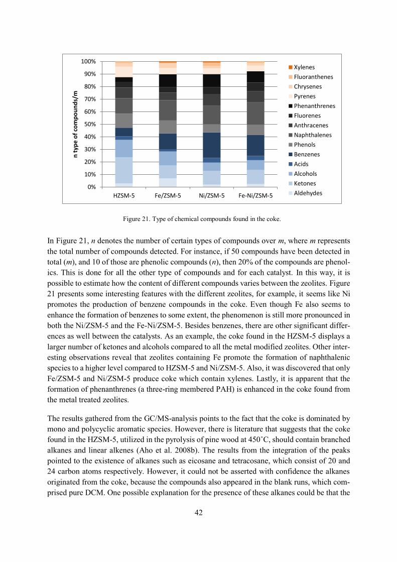
42
In Figure 21, n denotes the number of certain types of compounds over m, where m represents
the total number of compounds detected. For instance, if 50 compounds have been detected in
total (m), and 10 of those are phenolic compounds (n), then 20% of the compounds are phenol-
ics. This is done for all the other type of compounds and for each catalyst. In this way, it is
possible to estimate how the content of different compounds varies between the zeolites. Figure
21 presents some interesting features with the different zeolites, for example, it seems like Ni
promotes the production of benzene compounds in the coke. Even though Fe also seems to
enhance the formation of benzenes to some extent, the phenomenon is still more pronounced in
both the Ni/ZSM-5 and the Fe-Ni/ZSM-5. Besides benzenes, there are other significant differ-
ences as well between the catalysts. As an example, the coke found in the HZSM-5 displays a
larger number of ketones and alcohols compared to all the metal modified zeolites. Other inter-
esting observations reveal that zeolites containing Fe promote the formation of naphthalenic
species to a higher level compared to HZSM-5 and Ni/ZSM-5. Also, it was discovered that only
Fe/ZSM-5 and Ni/ZSM-5 produce coke which contain xylenes. Lastly, it is apparent that the
formation of phenanthrenes (a three-ring membered PAH) is enhanced in the coke found from
the metal treated zeolites.
The results gathered from the GC/MS-analysis points to the fact that the coke is dominated by
mono and polycyclic aromatic species. However, there is literature that suggests that the coke
found in the HZSM-5, utilized in the pyrolysis of pine wood at 450˚C, should contain branched
alkanes and linear alkenes (Aho et al. 2008b). The results from the integration of the peaks
pointed to the existence of alkanes such as eicosane and tetracosane, which consist of 20 and
24 carbon atoms respectively. However, it could not be asserted with confidence the alkanes
originated from the coke, because the compounds also appeared in the blank runs, which com-
prised pure DCM. One possible explanation for the presence of these alkanes could be that the
0%
10%
20%
30%
40%
50%
60%
70%
80%
90%
100%
HZSM-5 Fe/ZSM-5 Ni/ZSM-5 Fe-Ni/ZSM-5
n t
yp
e o
f co
mp
ou
nd
s/m
Xylenes
Fluoranthenes
Chrysenes
Pyrenes
Phenanthrenes
Fluorenes
Anthracenes
Naphthalenes
Phenols
Benzenes
Acids
Alcohols
Ketones
Aldehydes
Figure 21. Type of chemical compounds found in the coke.
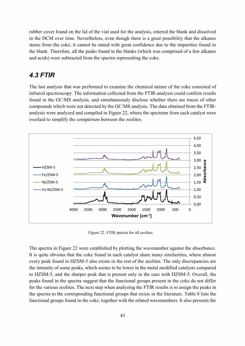
43
rubber cover found on the lid of the vial used for the analysis, entered the blank and dissolved
in the DCM over time. Nevertheless, even though there is a great possibility that the alkanes
stems from the coke, it cannot be stated with great confidence due to the impurities found in
the blank. Therefore, all the peaks found in the blanks (which was comprised of a few alkanes
and acids) were subtracted from the spectra representing the coke.
4.3 FTIR
The last analysis that was performed to examine the chemical nature of the coke consisted of
infrared spectroscopy. The information collected from the FTIR-analysis could confirm results
found in the GC/MS analysis, and simultaneously disclose whether there are traces of other
compounds which were not detected by the GC/MS analysis. The data obtained from the FTIR-
analysis were analyzed and compiled in Figure 22, where the spectrum from each catalyst were
overlaid to simplify the comparison between the zeolites.
The spectra in Figure 22 were established by plotting the wavenumber against the absorbance.
It is quite obvious that the coke found in each catalyst share many similarities, where almost
every peak found in HZSM-5 also exists in the rest of the zeolites. The only discrepancies are
the intensity of some peaks, which seems to be lower in the metal modified catalysts compared
to HZSM-5, and the sharper peak that is present only in the case with HZSM-5. Overall, the
peaks found in the spectra suggest that the functional groups present in the coke do not differ
for the various zeolites. The next step when analyzing the FTIR results is to assign the peaks in
the spectra to the corresponding functional groups that exists in the literature. Table 8 lists the
functional groups found in the coke, together with the related wavenumbers. It also presents the
0,00
0,50
1,00
1,50
2,00
2,50
3,00
3,50
4,00
4,50
05001000150020002500300035004000
Ab
so
rba
nc
e
Wavenumber [cm-1]
HZSM-5
Fe/ZSM-5
Ni/ZSM-5
Fe-Ni/ZSM-5
Figure 22. FTIR spectra for all zeolites.
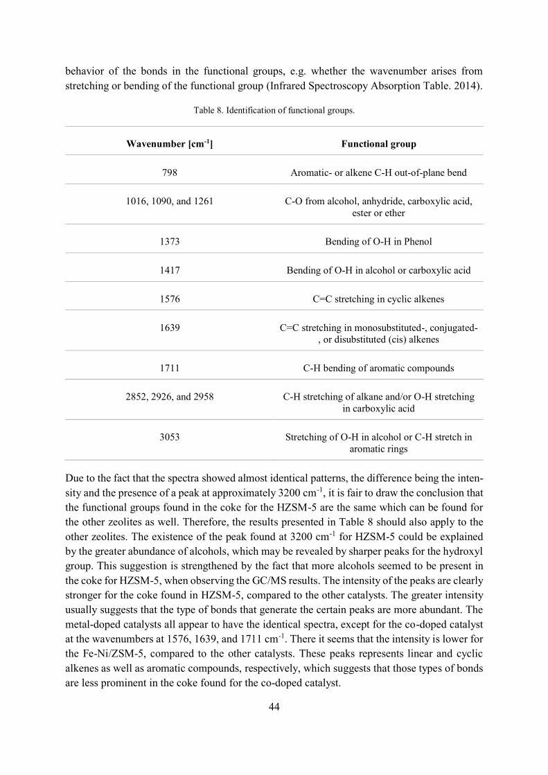
44
behavior of the bonds in the functional groups, e.g. whether the wavenumber arises from
stretching or bending of the functional group (Infrared Spectroscopy Absorption Table. 2014).
Table 8. Identification of functional groups.
Wavenumber [cm-1] Functional group
798 Aromatic- or alkene C-H out-of-plane bend
1016, 1090, and 1261 C-O from alcohol, anhydride, carboxylic acid,
ester or ether
1373 Bending of O-H in Phenol
1417 Bending of O-H in alcohol or carboxylic acid
1576 C=C stretching in cyclic alkenes
1639 C=C stretching in monosubstituted-, conjugated-
, or disubstituted (cis) alkenes
1711 C-H bending of aromatic compounds
2852, 2926, and 2958 C-H stretching of alkane and/or O-H stretching
in carboxylic acid
3053 Stretching of O-H in alcohol or C-H stretch in
aromatic rings
Due to the fact that the spectra showed almost identical patterns, the difference being the inten-
sity and the presence of a peak at approximately 3200 cm-1, it is fair to draw the conclusion that
the functional groups found in the coke for the HZSM-5 are the same which can be found for
the other zeolites as well. Therefore, the results presented in Table 8 should also apply to the
other zeolites. The existence of the peak found at 3200 cm-1 for HZSM-5 could be explained
by the greater abundance of alcohols, which may be revealed by sharper peaks for the hydroxyl
group. This suggestion is strengthened by the fact that more alcohols seemed to be present in
the coke for HZSM-5, when observing the GC/MS results. The intensity of the peaks are clearly
stronger for the coke found in HZSM-5, compared to the other catalysts. The greater intensity
usually suggests that the type of bonds that generate the certain peaks are more abundant. The
metal-doped catalysts all appear to have the identical spectra, except for the co-doped catalyst
at the wavenumbers at 1576, 1639, and 1711 cm-1. There it seems that the intensity is lower for
the Fe-Ni/ZSM-5, compared to the other catalysts. These peaks represents linear and cyclic
alkenes as well as aromatic compounds, respectively, which suggests that those types of bonds
are less prominent in the coke found for the co-doped catalyst.
45
The FTIR-results confirm the findings in the GC/MS-analysis, namely that there are aromatic
and cyclic compounds present in the coke. The question was if the FTIR-analysis could detect
traces of other compounds, perhaps alkanes and alkenes which were suggested by some litera-
ture. It seems to be evidence which support the fact that there are various types of alkenes
present in the coke. Although, proving that alkanes are present is more difficult because the
frequency assigned for both the C-H and O-H stretching coincides with each other. To answer
this question with greater certainty demands further testing, perhaps by using liquid chroma-
tography coupled with an ultraviolet detector. Otherwise, besides aromatics and alkenes, it is
interesting to observe that the bending of the hydroxyl group found in phenol can be detected
by the FTIR. Phenols were also discovered in the GC/MS analysis in great abundance, which
makes this finding plausible. The detection of carbonyl compounds is also in line with the
GC/MS-results, which implies that in overall, the results from the GC/MS and FTIR fit together
quite well.
4.4 Final remarks
Going back to the discussion regarding the lowered combustion temperature observed when
introducing metals in the zeolite, it is crucial to highlight the importance of this discovery based
on mainly the following reasons. First and foremost, the fact that the presence of metals seems
to lower the oxidation temperature in the TGA results reveals that less heat is needed to combust
the coke, which results in the fact that the catalyst will suffer less damage, such as sintering and
dealumination. This in turn will prolong the lifetime of the catalysts and reduce the need of
replacing it as often. Another benefit that follows from the lowered heat requirements is of
course the energy savings that could be made by not having to achieve elevated temperatures
to oxidize the coke. Furthermore, there is one topic that has been left out from the discussion
up to this point, namely the environmental and health aspect connected to the release of chem-
icals derived from the coke. As the qualitative analyses conducted throughout this work demon-
strates, is that a lot of aromatic hydrocarbons are formed in the coke which originates from the
CFP of biomass. It is known that some PAHs may pose a threat to human health during exposure
(ATSDR 2015). It is therefore crucial that the release of PAHs and other aromatic compounds
into the environment is kept at a minimum by, for example, implementing proper gas cleaning
operations.

46
47
5 CONCLUSIONS
Based on the results obtained from the different analyses, there are clearly some significant
differences on the properties of the coke generated from the protonated zeolite, compared to the
metal modified ditto. The TGA revealed that the relative coke amount was the following:
Fe/ZSM-5 (9.1%), Fe-Ni/ZSM-5 (7.9%), Ni/ZSM-5 (7.8%), and HZSM-5 (4.9%). By compar-
ing the most severely coked catalyst, the Fe/ZSM-5, with the least severely coked HZSM-5, it
turns out that coking increases by 84% when doping the catalyst with Fe. It can be stated that
the metal itself somehow alters the chemical pathway and reactions that are undergone during
the catalytic upgrading of the pyrolysis vapors. The catalytic mechanisms involved in the coke
formation for the Fe/ZSM-5 is yet unknown. Its discussion in the literature is also quite limited.
However, Ni is much more discussed, and it is hypothesized that due to the ability of Ni to
promote dehydrogenation and cyclization reactions, the formation of PAHs can increase. Fur-
thermore, it was also enlightening to discover the difference among the TGA-curves associated
with the different zeolites. As it was speculated in the results and discussion part, the thermo-
gravimetric behavior of the coke is probably due to a combined effect between the presence of
metal and the difference in chemistry among the coke. For example, Fe modified zeolite gave
rise to a curve which seemed to indicate that the regeneration temperature of the coke was
lowered compared to HZSM-5. This was likely because Fe catalyzed the reaction towards less
PAHs, and thus reducing the oxidation temperature. However, it is also known that the presence
of metals can help by lowering the regeneration temperature. Nevertheless, there are clearly
differences in the thermal properties of the coke when these transition metals are introduced in
the zeolite.
The results from the GC/MS analysis also show that there are differences in the formation of
certain compounds found in the coke. The nature of the coke still appears to be similar between
the different cases, in the sense that PAHs dominate the species found in the coke for all cata-
lysts. The content of MAHs in the coke were clearly highest for the Fe/ZSM-5, while coke
contained most ketones and alcohols in the HZSM-5. Worth noting was that benzenes and naph-
thalenes in the coke increased for the metal-doped zeolites, especially in the case of Ni. The
major constituent found in the coke for all cases, except the Ni case, was 1H-phenalen-1-one.
This compound was also mentioned in the literature as the dominant aromatic compound found
in the coke generated from biomass pyrolysis. In the case of Ni, the content of 2-methyl-phe-
nanthrene was most abundant in the coke.
The FTIR analysis did not reveal any remarkable differences between the various investigated
catalysts. As it only shows the presence of certain functional groups, it is not surprising that the
spectra were almost identical to each other. The results from the FTIR confirms the findings
from the GC/MS analysis almost fully. Carbonyl compounds as well as stretching and bending
of C-H and C=C were detected. The C-H stretching and C=C bending did show typical signs
of aromatic compounds, and the peaks for C=O bonds were most likely linked to ketones and
aldehydes found in the coke.

48
49
6 RECOMMENDATIONS AND FUTURE WORK
Coking on catalyst structures has long been a major issue that many industries dealing with
catalysis must face. The catalyst fouling requires measures such as regeneration, which in the
long run puts a lot of strain on the catalyst structure. Over time, this has the implication of
shortened catalyst life time, which demands more frequent replacement of the catalyst. This in
turn lead to a greater demand of energy input to sustain the combustion of coke in the regener-
ation process.
As it appears that Fe modification of zeolites lowers the combustion temperature of the coke, it
could reduce the stress on the zeolites that are associated with elevated temperature exposure.
Effects such as sintering and dealumination could be mitigated and the life time of the catalyst
increased, which could have positive economic effects for industries. However, it was also
shown that Fe produced the highest amount of coke. Therefore, it is important to investigate
not only the coking of the different zeolites but also the changes that might occur in the primary
pyrolysis products that are formed. For instance, if the properties of the bio-oil are vastly im-
proved when using a particular zeolite, then this fact together with the information about the
coking need to be considered, to enable a more comprehensive analysis. Perhaps there are cer-
tain compounds in the bio-oil that are more attractive than others, and if it is found that one of
the zeolites promotes the formation of this desired substance, then it must be put in relation to
the coking tendencies as well. To fully understand the benefits and limitations of certain both
modified- and unmodified zeolites, it is crucial to compare the results obtained in this thesis
with other findings about the properties- and yield of bio-oil, production of char et cetera. Solely
focusing on the coking results may not provide a justified picture about the benefits of all the
catalysts investigated.
It is exciting to observe that the presence of transition metals catalyzes the reactions in different
ways. The variability of the chemical nature of the coke indicate that there might be differences
in e.g. the bio-oil as well, which opens new possibilities in the catalysis industry. The depend-
ency on crude oil will probably not vanish for a long time, however, using bio-oil as a comple-
ment and proceeding with the development of the CFP-process over time, might enable the
replacement of crude oil in the future. As crude oil is not an endless resource, the need to find
a renewable and environmentally friendly substitute is of great importance to ensure a smooth
transition for industrial production processes in the future.

50
51
7 REFERENCES
Aho, A., Kumar, N., Eränen, K., Salmi, T., Hupa, M.M. and Murzin, D.Y. 2008a. Catalytic pyrolysis of woody
biomass in a fluidized bed reactor: Influence of the zeolite structure. Fuel 87(12), pp. 2493–2501. doi:
10.1016/j.fuel.2008.02.015.
Aho, A., Kumar, N., Eränen, K., Salmi, T., Hupa, M.M. and Murzin, D.Y. 2008b. Catalytic pyrolysis of woody
biomass in a fluidized bed reactor: Influence of the zeolite structure. Fuel 87(12), pp. 2493–2501. doi:
10.1016/j.fuel.2008.02.015.
Aho, A., Salmi, T. and Murzin, D. Y. 2013. Chapter 5 - Catalytic Pyrolysis of Lignocellulosic Biomass A2 - Triantafyllidis,
Kostas S. In: Lappas, A. A. and Stöcker, M. eds. The Role of Catalysis for the Sustainable Production of Bio-fuels and Bio-
chemicals. Amsterdam: Elsevier, pp. 137–159. doi: 10.1016/B978-0-444-56330-9.00005-X.
ATSDR - Public Health Statement: Polycyclic Aromatic Hydrocarbons (PAHs). [2015]. Available at:
https://www.atsdr.cdc.gov/phs/phs.asp?id=120&tid=25 [Accessed: 15 January 2018].
Avidan, A.A. 1997. Fluid catalytic cracking. In: Circulating Fluidized Beds. Springer, Dordrecht, pp. 466–488. doi:
10.1007/978-94-009-0095-0_13.
Basu, P. 2013. Chapter 5 - Pyrolysis. In: Biomass Gasification, Pyrolysis and Torrefaction (Second Edition). Boston: Academic Press,
pp. 147–176. doi: 10.1016/B978-0-12-396488-5.00005-8.
Bridgwater, A.V. 2012. Upgrading biomass fast pyrolysis liquids. Environmental Progress & Sustainable Energy
31(2), pp. 261–268. doi: 10.1002/ep.11635.
Busca, G. 2017. Acidity and basicity of zeolites: A fundamental approach. Microporous and Mesoporous Materials
254, pp. 3–16. doi: 10.1016/j.micromeso.2017.04.007.
Cerqueira, H.S., Caeiro, G., Costa, L. and Ribeiro, F.R. 2008. Deactivation of FCC catalysts. doi: 10.1016/j.mol-
cata.2008.06.014.
Chester, A.W. and Derouane, E.G. 2009. Zeolite Characterization and Catalysis: A Tutorial. Springer Science &
Business Media. doi: 10.1007/978-1-4020-9678-5.
Coman, S.M. and Parvulescu, V.I. 2013. Chapter 4 - Heterogeneous Catalysis for Biodiesel Production
A2 - Triantafyllidis, Kostas S. In: Lappas, A. A. and Stöcker, M. eds. The Role of Catalysis for the Sus-
tainable Production of Bio-fuels and Bio-chemicals. Amsterdam: Elsevier, pp. 93–136. doi:
10.1016/B978-0-444-56330-9.00004-8.
Czernik, S. and Bridgwater, T. 2004. Overview of Applications of Biomass Fast Pyrolysis Oil. doi: 10.1021/ef034067u.
Damjanović, L. and Auroux, A. 2009. Determination of Acid/Base Properties by Temperature Pro-grammed Desorption (TPD) and Adsorption Calorimetry. In: Chester, A. W. and Derouane, E. G. eds.
Zeolite Characterization and Catalysis: A Tutorial. Dordrecht: Springer Netherlands, pp. 107–167. doi:
10.1007/978-1-4020-9678-5_3.
Dost, K. and İdeli, C. 2012. Determination of polycyclic aromatic hydrocarbons in edible oils and barbecued food by
HPLC/UV–Vis detection. Food Chemistry 133(1), pp. 193–199. doi: 10.1016/j.foodchem.2012.01.001.
Eser, S. 2017. Fluid Catalytic Cracking (FCC). Available at: https://www.e-education.psu.edu/fsc432/content/fluid-
catalytic-cracking-fcc [Accessed: 14 September 2017].
52
Fahmi, R., Bridgwater, A.V., Darvell, L.I., Jones, J.M., Yates, N., Thain, S. and Donnison, S.I. 2007. The effect of
alkali metals on combustion and pyrolysis of Lolium and Festuca grasses, switchgrass and willow. Fuel 86(10), pp.
1560–1569. doi: 10.1016/j.fuel.2006.11.030.
Guisnet, M. 2007. Zeolite Catalysts for Cleaner Technologies. In: Tundo, P. et al. eds. Methods and Reagents for
Green Chemistry. John Wiley & Sons, Inc., pp. 231–249. doi: 10.1002/9780470124086.ch12.
Guisnet, M. and Magnoux, P. 2001. Organic chemistry of coke formation. Applied Catalysis A: General 212(1), pp.
83–96. doi: 10.1016/S0926-860X(00)00845-0.
Gusev, A., Psarras, A.C., Papapetrou, M., Iatridis, D., Iliopoulou, E.F. and Lappas, A.A. 2015. Effect of Hydro-
Thermal Treatment (Steaming) Temperature on the Deactivation of ZSM-5 Additives in FCC Process. Available
at: http://pesxm10.chemeng.upatras.gr/sites/default/files/papers/P01/10PESXM_P0383_A.GUSEV__0.pdf [Ac-
cessed: 14 September 2017].
Heat values of various fuels - World Nuclear Association. [2016]. Available at: http://www.world-nu-
clear.org/information-library/facts-and-figures/heat-values-of-various-fuels.aspx [Accessed: 15 January
2018].
Iliopoulou, E.F., Stefanidis, S.D., Kalogiannis, K.G. and Triantafyllidis, K.S. 2012. Catalytic upgrading of biomass
pyrolysis vapors using transition metal-modified ZSM-5 zeolite. Applied Catalysis B: Environmental 127, pp. 281–290. doi: 10.1016/j.apcatb.2012.08.030.
InfraredSpectroscopyAbsorptionTable.2014.Availableat: https://chem.libretexts.org/Reference/Refer-
ence_Tables/Spectroscopic_Parameters/Infrared_Spectroscopy_Absorption_Table [Accessed: 15 Janu-
ary 2018].
Jiang, X., Zhou, J., Zhao, J. and Shen, D. 2017a. Catalytic conversion of guaiacol as a model compound for aromatic
hydrocarbon production. Biomass and Bioenergy . doi: 10.1016/j.biombioe.2017.06.026.
Jiang, X., Zhou, J., Zhao, J. and Shen, D. 2017b. Catalytic conversion of guaiacol as a model compound for aromatic
hydrocarbon production. Biomass and Bioenergy . doi: 10.1016/j.biombioe.2017.06.026.
Johari, A. and Rozainee, M. 2007. EFFECT OF SAND SIZES ON THE FLUIDIZATION BEHAVIOR IN CIRCU-
LAR AND RECTANGULAR COLUMNS. Available at: https://www.researchgate.net/publication/237752242_EF-
FECT_OF_SAND_SIZES_ON_THE_FLUIDIZATION_BEHAVIOR_IN_CIRCULAR_AND_RECTANGU-
LAR_COLUMNS. [Accessed: 20 September 2017].
Jukić,A.2013.PetroleumRefiningandPetrochemicalProcesses.Availableat:
https://www.fkit.unizg.hr/_download/repository/PRPP_2013_Crude_oil_composition.pdf [Accessed:
20 September 2017].
Klimisch, H.J., Andreae, M. and Tillman, U. 1997. A systematic approach for evaluating the quality of
experimental toxicological and ecotoxicological data. Available at: http://www.petroleumhpv.org/petro-
leum-substances-and-categories/~/media/89F496D8432545ABB06D85D0BD5D99D1.ashx [Accessed:
21 September 2017].
Komvokis, V., Tan, L.X.L., Clough, M., Pan, S.S. and Yilmaz, B. 2016. Zeolites in Fluid Catalytic Crack-
ing (FCC). In: Zeolites in Sustainable Chemistry. Green Chemistry and Sustainable Technology. Springer,
Berlin, Heidelberg, pp. 271–297. doi: 10.1007/978-3-662-47395-5_8.
Li, Y., Zhang, C., Liu, Y., Tang, S., Chen, G., Zhang, R. and Tang, X. 2017. Coke formation on the surface of
Ni/HZSM-5 and Ni-Cu/HZSM-5 catalysts during bio-oil hydrodeoxygenation. Fuel 189(Supplement C), pp. 23–31.
doi: 10.1016/j.fuel.2016.10.047.
53
Liu, C., Wang, H., Karim, A.M., Sun, J. and Wang, Y. 2014. Catalytic fast pyrolysis of lignocellulosic biomass.
Chemical Society Reviews 43(22), pp. 7594–7623. doi: 10.1039/C3CS60414D.
Magnoux, P., Roger, P., Canaff, C., Fouche, V., Gnep, N.S. and Guisnet, M. 1987. New Technique for the Characteri-
zation of Carbonaceous Compounds Responsible for Zeolite Deactivation. In: Delmon, B. and Froment, G. F. eds.
Studies in Surface Science and Catalysis. Catalyst Deactivation 1987. Elsevier, pp. 317–330. doi: 10.1016/S0167-
2991(09)60370-0.
Mohamed, M.A., Jaafar, J., Ismail, A.F., Othman, M.H.D. and Rahman, M.A. 2017. Chapter 1 - Fourier Transform
Infrared (FTIR) Spectroscopy. In: Membrane Characterization. Elsevier, pp. 3–29. doi: 10.1016/B978-0-444-
63776-5.00001-2.
Mullen, C.A. and Boateng, A.A. 2015. Production of Aromatic Hydrocarbons via Catalytic Pyrolysis of Biomass
over Fe-Modified HZSM-5 Zeolites. ACS Sustainable Chemistry & Engineering 3(7), pp. 1623–1631. doi:
10.1021/acssuschemeng.5b00335.
Müller, M., Harvey, G. and Prins, R. 2000. Comparison of the dealumination of zeolites beta, mordenite, ZSM-5 and
ferrierite by thermal treatment, leaching with oxalic acid and treatment with SiCl4 by 1H, 29Si and 27Al MAS NMR.
Microporous and Mesoporous Materials 34(2), pp. 135–147. doi: 10.1016/S1387-1811(99)00167-5.
PerkinElmer-ATRaccessories-Anoverview.[2004].Availableat: https://shop.perkinelmer.com/Content/tech-
nicalinfo/tch_atraccessories.pdf [Accessed: 15 January 2018].
Pinho, A. de R., Marlon, B.B. de A., Mendes, F.L., Casavechia, L.C., Talmadge, M.S., Kinchin, C.M. and Chum,
H.L. 2017. Fast pyrolysis oil from pinewood chips co-processing with vacuum gas oil in an FCC unit for second
generation fuel production. Fuel 188, pp. 462–473. doi: 10.1016/j.fuel.2016.10.032.
Ramakers, B.J., Ridder, de R. and Kerkhof, P.J.A.M. 2004. FLUIDIZATION BEHAVIOR OF WOOD/SAND
MIXTURES. Maderas. Ciencia y tecnología 6(2), pp. 145–153. doi: 10.4067/S0718-221X2004000200005.
Sadeghbeigi, R. 2012. Chapter 1 - Process Description. In: Fluid Catalytic Cracking Handbook (Third Edition). Oxford: But-
terworth-Heinemann, pp. 1–42. doi: 10.1016/B978-0-12-386965-4.00001-X.
Saraçoğlu, E., Uzun, B.B. and Apaydin-Varol, E. 2017. Upgrading of fast pyrolysis bio-oil over Fe modified ZSM-
5 catalyst to enhance the formation of phenolic compounds. International Journal of Hydrogen Energy 42(33), pp.
21476–21486. doi: 10.1016/j.ijhydene.2017.07.001.
Satyanarayana, C.V. et al. 2016. Chapter 5 - Catalyst Deactivation and Regeneration. In: Joshi, S. S. and Ranade, V.
V. eds. Industrial Catalytic Processes for Fine and Specialty Chemicals. Amsterdam: Elsevier, pp. 187–219. doi:
10.1016/B978-0-12-801457-8.00005-7.
Serrano-Ruiz, J.C. and Dumesic, J.A. 2012. Catalytic Production of Liquid Hydrocarbon Transportation Fuels. In:
Guczi, L. and Erdôhelyi, A. eds. Catalysis for Alternative Energy Generation. New York, NY: Springer New York,
pp. 29–56. doi: 10.1007/978-1-4614-0344-9_2.
Shao, S., Zhang, H., Xiao, R., Li, X. and Cai, Y. 2017. Catalytic conversion of biomass-derivates by in situ DRIFTS:
Evolution of coke. Journal of Analytical and Applied Pyrolysis . doi: 10.1016/j.jaap.2017.07.026.
Subramanian, A. and Rodriguez-Saona, L. 2009. Chapter 7 - Fourier Transform Infrared (FTIR) Spectroscopy. In:
Sun, D.-W. ed. Infrared Spectroscopy for Food Quality Analysis and Control. San Diego: Academic Press, pp. 145–178. doi: 10.1016/B978-0-12-374136-3.00007-9.
54
Sun, L., Zhang, X., Chen, L. and Xie, X. 2016a. Comparision of catalytic fast pyrolysis of biomass to
aromatic hydrocarbons over ZSM-5 and Fe/ZSM-5 catalysts. Journal of Analytical and Applied Pyrolysis
121(Supplement C), pp. 342–346. doi: 10.1016/j.jaap.2016.08.015.
Sun, L., Zhang, X., Chen, L. and Xie, X. 2016b. Comparision of catalytic fast pyrolysis of biomass to aromatic hydrocarbons
over ZSM-5 and Fe/ZSM-5 catalysts. Journal of Analytical and Applied Pyrolysis 121. doi: 10.1016/j.jaap.2016.08.015.
Wang, H., Elliott, D.C., French, R.J., Deutch, S. and Iisa, K. 2016. Biomass Conversion to Produce Hydrocarbon
Liquid Fuel Via Hot-vapor Filtered Fast Pyrolysis and Catalytic Hydrotreating. Journal of Visualized Experiments : JoVE (118), p. 54088. doi: 10.3791/54088.
Wang, S., Dai, G., Yang, H. and Luo, Z. 2017. Lignocellulosic biomass pyrolysis mechanism: A state-of-the-art
review. Progress in Energy and Combustion Science 62(Supplement C), pp. 33–86. doi: 10.1016/j.pecs.2017.05.004.
World Nuclear Association - Heat Values of various fuels. [2016]. Available at: http://www.world-nu-
clear.org/information-library/facts-and-figures/heat-values-of-various-fuels.aspx [Accessed: 15 January
2018].
Yang, H., Coolman, R., Karanjkar, P., Wang, H., Dornath, P., Chen, H., Fan, W., Conner, W.C., Mountziaris, T.J.
and Huber, G. 2017. The effects of contact time and coking on the catalytic fast pyrolysis of cellulose. Green Chem-
istry 19(1), pp. 286–297. doi: 10.1039/C6GC02239A.
Yao, W., Li, J., Feng, Y., Wang, W., Zhang, X., Chen, Q., Komarneni, S. and Wang, Y. 2015. Thermally stable
phosphorus and nickel modified ZSM-5 zeolites for catalytic co-pyrolysis of biomass and plastics. RSC Advances
5(39), pp. 30485–30494. doi: 10.1039/C5RA02947C.
Zhang, H., Shao, S., Xiao, R., Shen, D. and Zeng, J. 2014. Characterization of Coke Deposition in the Catalytic Fast
Pyrolysis of Biomass Derivates. Energy & Fuels 28(1), pp. 52–57. doi: 10.1021/ef401458y.

55

www.kth.se