coexistence test of lte and radar systems application note · coexistence test of lte and radar...
TRANSCRIPT

Coexistence Test of LTE and Radar Systems Application Note
Products:
ı R&S®CMW500
ı R&S®SMW200A
ı R&S®TSMW
ı R&S®IQR
ı R&S®ARB Toolbox
Plus
ı R&S®TS6650
ı R&S®SMBV100A
ı R&S®FSL
ı R&S®OSP
Air Traffic Control (ATC) radar, military Air Traffic
Surveillance (ATS) radar and meteorological radar
operate in S-Band frequency range. In fact 4G
communication systems such as Long Term
Evolution (LTE) make also use of these frequencies.
Test and measurement of their coexistence is
absolutely essential as performance degradation of
mobile devices and networks and even malfunction
of ATC radars has been proven.
This application note describes LTE and S-Band
radar coexistence test and measurement. It
addresses LTE user equipment, base stations and
S-Band radars and presents test solutions.
Dr.
Ste
ffen
Heu
el,
Rol
and
Min
ihol
d
3.20
14 -
1M
A21
1_0e
App
licat
ion
Not
e

Table of Contents
1MA211_0e Rohde & Schwarz Coexistence Test of LTE and Radar Systems 2
Table of Contents
1 Introduction ......................................................................................... 3
2 Mobile Networks and Radar Systems ............................................... 4
2.1 Air Traffic Control Radar ............................................................................................. 7
3 Hardware and Software Requirements ............................................. 8
3.1 Mandatory Requirements ............................................................................................ 8
3.2 Optional Hardware and Software Requirements ...................................................... 8
3.2.1 Vector Signal Generator ................................................................................................ 9
3.2.2 Universal Radio Network Analyzer and Data Recorder................................................. 9
3.2.3 ARB Toolbox ................................................................................................................10
3.2.4 RF Shield Box ..............................................................................................................11
4 Test & Measurement of LTE Mobiles .............................................. 12
4.1 Recording of Radar Signals ......................................................................................12
4.2 Measurement Setup ...................................................................................................12
4.3 Measurement Configuration .....................................................................................15
4.3.1 BLER and throughput measurement without disturbing signal ...................................15
4.3.2 BLER and throughput measurement with disturbing signal ........................................18
5 Test & Measurement of Radar Systems .......................................... 25
5.1 Test System Description ...........................................................................................25
5.2 Supported Scenarios .................................................................................................27
5.3 TS6650 Radar Interference Tester Setup ................................................................28
5.3.1 Waveform File Structure ..............................................................................................28
5.4 Measurement Results ................................................................................................30
6 Mitigation Techniques ...................................................................... 32
7 Literature ........................................................................................... 33
8 Ordering Information ........................................................................ 34

Introduction
1MA211_0e Rohde & Schwarz Coexistence Test of LTE and Radar Systems 3
1 Introduction
Air Traffic Control (ATC) radar, military Air Traffic Surveillance (ATS) radar and
meteorological radar operate in S-Band frequency range, which has been defined by
IEEE as all frequencies between 2 to 4 GHz. Next to aviation and weather forecast,
several different maritime radars worldwide also operate in this frequency band. The
excellent meteorological and propagation characteristics make the use of this
frequency band beneficial for radar operation. And not just for radar. These
frequencies are of special interest also for wireless communications. In fact, 4G
communications systems such as UMTS long-term evolution (LTE) make use of these
frequencies as well.
The 3rd Generation Partnership Project (3GPP) and standardization body behind LTE
started its work on this new technology back in 2004. Four years later, in December
2008, the work on the initial version of the standard was finished and published as part
of 3GPP Release 8 for all relevant technical specifications. With the version from
07/2013 of the LTE standard there are in total 41 frequency bands specified. Some of
these frequency bands are fairly close to operational S-Band radar systems which
demand coexistence tests, measurements and verification to ensure proper functioning
of both radar and mobile communication.
Coexistence is not only of major interest in case of different systems operating in the
spectral and regional neighborhood. As known from mobile communication,
interference between base stations can also occur in presence of another base station
operating in the same regional area. Automotive radar systems may also face
coexistence challenges. With any deployed radar sensor for automotive safety
applications such as blind spot detection, pedestrian protection or automated cruise
control, the noise floor for other radar sensors operating in the same spectral band and
regional area increases and detection becomes more difficult. These systems therefore
have to be tested in presence of similar radar signals.
This application note describes potential issues concerning S-Band radar systems and
LTE signals from base stations / mobile devices operating close-by. It addresses
frequency allocation of these systems, explains the performance degradation or
malfunction that can be expected and describes test and measurement solutions for
interference test of radar and LTE networks in detail.

Mobile Networks and Radar Systems
1MA211_0e Rohde & Schwarz Coexistence Test of LTE and Radar Systems 4
2 Mobile Networks and Radar Systems
Continuously increasing mobile data traffic and the demand for higher data throughput
of mobile devices requires higher spectral efficiency or the extension of allocable
frequencies, hence more bandwidth. For example in 2G mobile communication, the
Global System for Mobile Communications (GSM) a bandwidth of 200 kHz per channel
was specified. In comparison, LTE defines a bandwidth of 20 MHz per channel.
LTE is supposed to operate in two different modes, Frequency Division Duplex (FDD)
and Time Division Duplex (TDD). Both duplex modes are using different frequency
bands worldwide. With the latest version of the LTE standard there are in total 29
frequency bands for FDD and 12 frequency bands for TDD. Table 1 lists the LTE FDD
frequency bands, where the ones falling into the S-Band frequency range are marked
in yellow. The frequency bands that are fairly close to any operational S-Band radar
system are highlighted.
Table 1: LTE FDD frequency bands; frequency bands within S-Band are marked yellow
LTE base stations (BS) may be disturbed through radar systems. Depending on the
ATC or ATS radar system a power of up to 7000 MW EIRP is transmitted. The blocking
requirements of the LTE BS and mobile have therefore also to comply with these
figures; taken into account the distance of the BS or UE. TS36.141 defines the
blocking performance requirement for wide area BS as described in Table 2.
Table 2: Blocking performance requirement for Wide Area BS [1]

Mobile Networks and Radar Systems
1MA211_0e Rohde & Schwarz Coexistence Test of LTE and Radar Systems 5
The user equipment (UE) may even be closer to a radar system. According to 3GPP
TS36.521-1 out-of-band blocking parameters are defined as shown in Table 3.
Table 3: Out-of-band blocking parameters [1]
In 3GPP TS36.521-1 [1] the test purpose of "TC 7.6.2 Out-of-band blocking" is
described with an "Unwanted CW interfering signal falling more than 15 MHz below or
above the UE receive band, at which a given average throughput shall meet or exceed
the requirement…". Under minimum conformance requirements the throughput is
mentioned to be "≥95% of the maximum throughput of the reference measurement
channel".
As shown in several measurements, disturbance of LTE networks occurs through S-
Band radar, such as degradation of performance due to lower throughput indicated by
an increasing block error rate (BLER). Throughput reduction is unlikely, but not a major
drawback. However spectral efficiency, power reduction and costs are of great
importance for any mobile network operator. Therefore disturbance through other
signals is therefore of great interest.
Unlike mobile communication, radar is not defined by a global specification. Thus,
many different systems applying different waveforms, frequencies and bandwidth are
deployed and operate nearly autonomously to detect the desired kind of target. For a
radar engineer, bandwidth is also one of the key parameters when defining the radar
system, as bandwidth defines range resolution. Depending on the radar, bandwidth
can range from nearly zero (just a carrier frequency, CW radar) to measure radial
velocity up to several GHz for high resolution range measurements (e.g. Ultra
Wideband Radar, UWB).
The 2.7 GHz to 2.9 GHz frequency band is primarily allocated to aeronautical radio
navigation, i.e. ground based fixed and transportable radar platforms for meteorological
purposes and aeronautical radio navigation services. Operating frequencies of these
radars are assumed to be uniformly distributed throughout S-Band [4]. The two
frequency bands for mobile communication and aeronautical radio navigation are very
closely located; hence coexistence has to be proven.

Mobile Networks and Radar Systems
1MA211_0e Rohde & Schwarz Coexistence Test of LTE and Radar Systems 6
Figure 2-1: International Telecommunication Union Radio Regulations in the band of 2.5 GHz to 3.1
GHz [3]
Presence of LTE signals and less selective filters in the radar receiver can cause
significant interference or even damage. This can be indicated by false target detection
or by the high power state of the receiver protector. The latter can occur when LTE
signals and spurious emissions are very strong and received by the radar. In the case
of weaker signals or signals outside the nominal receiver bandwidth the radar could go
into compression and produce non-linear responses or react by raising the Constant
False Alarm Rate (CFAR) threshold. Thereby present targets can be lost in further
measurements and targets with low power echoes cannot be detected, hence the
maximum detection range or probability of detection is degraded [6].
Figure 2-2: Radar Amplifier Chain in the Frequency Domain and Out-Of-Band and In-Band
Interference
Test and measurement solutions were developed to apply different synthetic as well as
recorded signals to both LTE networks and S-Band radar systems. These test
solutions allow verification of proper functionality and in the case of interference or
even malfunction.
2.7 GHz 2.9 GHz Aeronautical Radionavigation
f
2.5 GHz 2.69 GHz
Mobile
Earth Exploration Satellite, Radio Astronomy
2.9 GHz 3.1 GHz Radionavigation

Mobile Networks and Radar Systems
1MA211_0e Rohde & Schwarz Coexistence Test of LTE and Radar Systems 7
2.1 Air Traffic Control Radar
There are many different types of Air Traffic Control (ATC) radar deployed worldwide.
Beside the frequency allocation, typical transmit power, antenna gain, maximum
ranges, opening angles of the antenna in horizontal or vertical direction, pulse duration,
pulse repetition frequency, duration time of a single turn of the antenna are of interest.
To get a feeling what type of signal and which power could disturb the receiver of the
LTE mobile or base station, the table below gives an overview of typical values.
Parameter Typical Values
Transmit Power 2 kW - 20 MW
Maximum Range 100 km - 500 km
Horizontal Antenna Opening Angle
0.4° - 2.5°
Pulse duration < 1µs - 400µs (most ATC radars use double pulses, e.g. 2 x 1µs or 2 x 2µs) Every single pulse is transmitted at a different frequency (frequency diversity) in a distance of about 10-20 MHz
Pulse period < 1ms - 4ms
Antenna rotation time 5 rounds/min - 15 rounds/min
Antenna gain 25 dBi - 40 dBi Table 4: Typical ATC radar parameters values
Some ATC radars also have different pulse waveform modes. The ASR-E for example
can operate in between 2.7 GHz and 2.9 GHz with 1µs and 2x 45µs pulse duration and
different antenna rotation times, e.g. 15 rounds/min or 12 rounds/minute [10].
For a successful test it is essential to know the radar or disturbing signal in detail and
either to rebuild it using an arbitrary waveform file generator or to record and to replay
the signal as described in this application note.

Hardware and Software Requirements
1MA211_0e Rohde & Schwarz Coexistence Test of LTE and Radar Systems 8
3 Hardware and Software Requirements
3.1 Mandatory Requirements
For chipset and wireless device testing the R&S®CMW500 Wideband Radio
Communication Tester is widely used throughout the industry. The unique design as a
flexible hardware platform enables the design engineer to use it for protocol and
signaling test, but also for RF parametric tests of transmitter and receiver performance
of a mobile terminal.
Figure 3-1: R&S CMW500 Wideband Radio Communication Tester
Hardware requirements:
ı R&S®CMW500
ı Mini-UICC Test Card, supp. 3GPP SIM/USIM/ISIM/CSIM (acc.)
Software requirements:
ı CMW LTE Signaling Version (LTE 3.2.70)
ı CMW General Purpose RF
ı LTE FDD R8, TX measurement, uplink (SL)
ı LTE FDD R8, SISO, basic signaling (SL)
ı LTE R8, SISO, advanced signaling (SL)
For the entire R&S®CMW500 product configuration it is referred to the ordering
information at the end of this application note.
3.2 Optional Hardware and Software Requirements
Optional hardware and software requirements enhance test and measurement
possibilities. Using the equipment below additional tests such as recorded RF

Hardware and Software Requirements
1MA211_0e Rohde & Schwarz Coexistence Test of LTE and Radar Systems 9
spectrum can be tested against LTE signaling using the CMW500. Also large
waveform files (*.wv-files) can be replayed using SMW200A.
Optional hardware and software requirements:
ı R&S®SMW200A
ı R&S®TSMW
ı R&S®IQR
ı R&S®ARB Toolbox Plus Windows
ı R&S®CMW Z-10 RF Shield Box
ı RF Combiner
ı RF Attenuator
3.2.1 Vector Signal Generator
For Signal Generation the vector signal generator R&S®SMW200A is used which
enables enhanced possibilities to verify selective filtering, BLER and throughput with
the CMW500, when adding a certain signal, e.g. jamming signal or radar signal. It is
also possible to use the R&S®SMBV100A as an interferer.
Figure 3-2: R&S SMW200A Vector Signal Generator
3.2.2 Universal Radio Network Analyzer and Data Recorder
R&S®TSMW Universal Radio Network Analyzer is used as a digital I/Q baseband
receiver which received data is stored on a R&S®IQR data recorder.
Figure 3-3: R&S TSMW and R&S IQR

Hardware and Software Requirements
1MA211_0e Rohde & Schwarz Coexistence Test of LTE and Radar Systems 10
Using the equipment above, arbitrary waveforms can be generated, as well as
recorded I/Q data can be replayed to perform coexistence tests of any present signal
and S-Band radar signal in particular.
3.2.3 ARB Toolbox
The ARB Toolbox Plus is an easy-to-use, feature packed software package that is
used for many ARB waveform related tasks, Figure 3-4. This software is the successor
of the ARB Toolbox which is bundled with the 1GP88 application note [7] and the CDM
Toolbox, described in application note 1GP96 [11].
This software is used for
ı creating ARB waveform files from custom IQ data,
ı import of data from MATLAB .mat files,
ı graphical evaluation of waveform content,
ı resampling or filtering of waveforms,
ı creation of analog modulated signals as ARB files,
ı editing marker data in waveform files,
ı creation of complex multi carrier scenarios.
Figure 3-4: ARB Toolbox Plus replaying recorded I/Q data (ATC radar)

Hardware and Software Requirements
1MA211_0e Rohde & Schwarz Coexistence Test of LTE and Radar Systems 11
3.2.4 RF Shield Box
The R&S®CMW-Z10 RF shielding box offers excellent shielding effectiveness,
superior coupling characteristics and can be used for frequencies up to 6 GHz. In this
measurement the DUT is placed inside the shielding box as depicted in Figure 4-1.
Figure 3-5: RF Shield Box

Test & Measurement of LTE Mobiles
1MA211_0e Rohde & Schwarz Coexistence Test of LTE and Radar Systems 12
4 Test & Measurement of LTE Mobiles
LTE Mobiles are tested in presence of recorded radar signals and in presence of
synthetic rebuild radar signals using arbitrary waveform generator (ARB). This chapter
addresses how to record radar signals, and describes the measurement setup and
methods.
4.1 Recording of Radar Signals
In order to test somewhat real-world conditions an S-Band radar signal is recorded and
played back on the desired frequency while performing a throughput test or receive
sensitivity test on LTE-capable terminal that is for example operational in Band 7. The
ATC radar signal is recorded at an airport using R&S®TSMW Universal Network
Scanner.
In this context the TSMW is tuned to the desired S-Band radar frequency to capture
the RF signal, perform the down conversion and thus convert the RF signal to IQ data.
As the amount of data can exceed the internal memory, R&S®IQR recorder is
connected via an internal interface directly to the TSMW. The IQ data can now be
streamed to the IQR and is stored on the 1 TByte harddrive.
The recorded I/Q data is transferred in the *.wv format to the R&S®CMW500 or
R&S®SMW200A either via an USB-stick or Ethernet connection.
For RF spectrum recording please see Application Note 1SP16 [2].
4.2 Measurement Setup
There are three possibilities to setup the measurement devices for coexistence tests:
1. Use the CMW with basic RF frontend and a HF combiner,
2. the CMW and SMW with HF combiner,
or
3. the CMW with advanced RF frontend.
In the first solution the Device Under Test (DUT) is connected as depicted in Figure
4-2.
RF 3 OUT is transmitting the radar signal which has been recorded.
RF 1 COM is in signaling mode connecting the DUT to the CMW500. Using an RF
combiner both signals are routed to the DUT.

Test & Measurement of LTE Mobiles
1MA211_0e Rohde & Schwarz Coexistence Test of LTE and Radar Systems 13
Figure 4-1: Measurement Setup using CMW500 and a LTE DUT
NOTE:
The RF output power of the DUT should not exceed the input
limits of the RF 3 OUT connector. Pleas add a proper RF
attenuator (e.g. 10 dB) in case the DUT transmits high power.
Figure 4-2: CMW500 and DUT Setup for LTE and S-Band Radar coexistence tests
Figure 4-2 shows the configuration in case of a CMW500 with a RF frontend with basic
functionality (product type CMW-S590A).
Another solution is to use the vector signal generator SMW200A as source of the
disturbing signal. The SMW200A has selectable predefined signals available, such as
pulse or CW signals which can also be used to verify coexistence. This setup also
CMW500
10dB Attenuator

Test & Measurement of LTE Mobiles
1MA211_0e Rohde & Schwarz Coexistence Test of LTE and Radar Systems 14
enhances flexibility to change the settings of the disturbing radar signal, as both
screens are visible simultaneously. The test setup is shown in Figure 4-3.
Figure 4-3: CMW500, SMW200A and DUT Setup for LTE and S-Band Radar coexistence tests
A third option is to use a CMW500 with the advanced frontend, RF Frontend
(Advanced) R&S CMW-B590D.
The interference signal is then routed to the same RF connector as the LTE uplink /
downlink signal. This setup reduces hardware and setup complexity and saves time
and cost.
Figure 4-4: CMW500 with advanced RF frontend and DUT
CMW500
SMW200A
10dB Attenuator
CMW500

Test & Measurement of LTE Mobiles
1MA211_0e Rohde & Schwarz Coexistence Test of LTE and Radar Systems 15
4.3 Measurement Configuration
After connection setup, start the CMW500 LTE signaling and perform the throughput
and BLER test without presence of any other signal with the parameters, described in
section 4.3.1.
In a second step the same test will be performed in presence of the radar signal as
described in section 4.3.2.
Comparing throughput and CQI measurements of section 4.3.1 and section 4.3.2 gives
a result about the performance of the DUT.
4.3.1 BLER and throughput measurement without disturbing signal
For the test, the maximum throughput and Channel Quality Indicator (CQI) of 15 was
determined adapting to the Reference Sensitivity Level (TS 36.521-1, 7.3) test.
Therefore OFDMA Channel Noise Generation (OCNG) has to be enabled in the R&S
CMW500 in order to simulate the existence of other users. The Active TPC Setup has
to be set to “Max Power” to ensure that the mobile (UE) power reaches its maximum.
In difference to TS 36.521-1, 7.3 the modulation scheme 64QAM in the DL and 16QAM
in the UL has to be selected. This ensures a maximum throughput at a given
sensitivity.
1. Start CMW500 and start the Signal Generator
ı Press: SIGNAL GENERATOR
2. Start LTE Signaling 1
ı Select: LTE Signaling 1
ı Press: ON
3. Select LTE Signaling 1 and change the signaling properties to
ı Operating Band 7
ı Cell Bandwidth 20.0 MHz
ı Connection Setup: Modulation 64 QAM Downlink, 16 QAM Uplink
4. Start the LTE Signaling and wait for DUT to establish the connection.
5. On successful connection, change the PCC frequency to
ı Frequency: 2680.0 MHz
Test & Measurement of LTE Mobiles
1MA211_0e Rohde & Schwarz Coexistence Test of LTE and Radar Systems 16
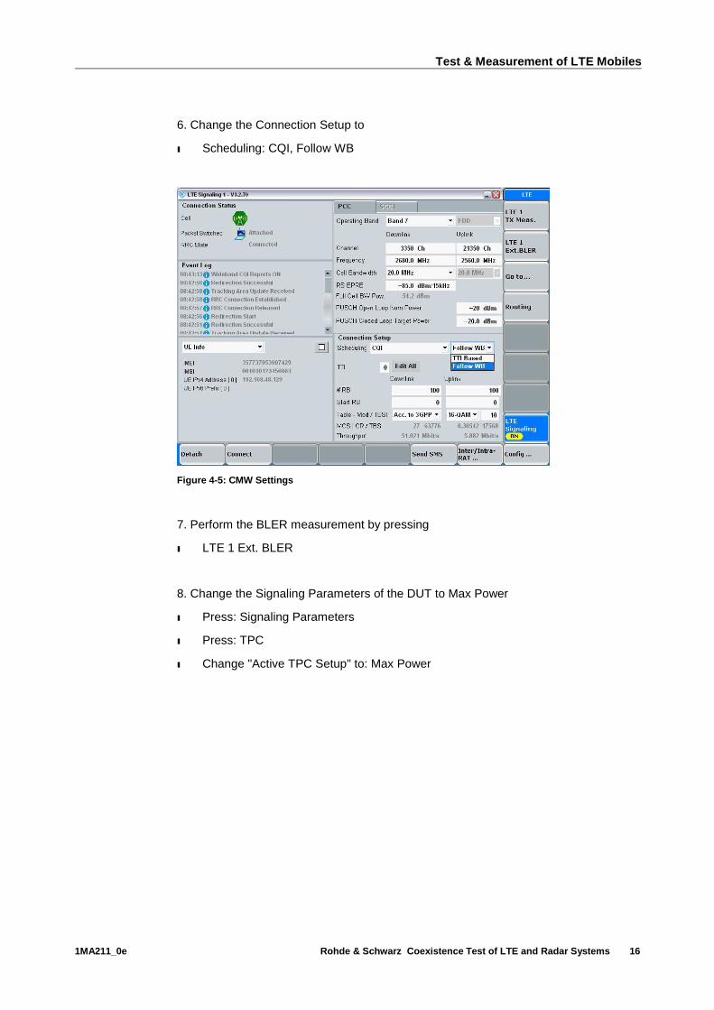
6. Change the Connection Setup to
ı Scheduling: CQI, Follow WB
Figure 4-5: CMW Settings
7. Perform the BLER measurement by pressing
ı LTE 1 Ext. BLER
8. Change the Signaling Parameters of the DUT to Max Power
ı Press: Signaling Parameters
ı Press: TPC
ı Change "Active TPC Setup" to: Max Power

Test & Measurement of LTE Mobiles
1MA211_0e Rohde & Schwarz Coexistence Test of LTE and Radar Systems 17
Figure 4-6: Active TCP Setup
9. Change the BLER Configuration to Single Shot
ı Press: Config
ı Select "Repetition": Single
ı Change "No. of Subframes": 50000
Figure 4-7: BLER Configuration

Test & Measurement of LTE Mobiles
1MA211_0e Rohde & Schwarz Coexistence Test of LTE and Radar Systems 18
10. Start BLER Measurement
ı Press: MEASURE
ı Select: Extended BLER 1
ı Press: ON
11. During the BLER Measurement:
ı Change the RS EPRE to a threshold value where the CQI toggles between two
desired values.
For example: high RS EPRE power results in a high CQI of 14 / 15. Lower power
represents a more realistic CQI of 5 to 7. Repeat the BLER measurement in that
purpose which satisfies your measurement needs.
In our example, Figure 4-8 shows that the RS EPRE was set to -104.5 dBm/15kHz,
which resulted in a CQI toggling between 5 and 6. The average throughput was
measured to be 9.18 Mbit/s and a BLER of 1.66%. This is a realistic value which is
also measured in the field.
Figure 4-8: BLER Measurement and Cell Setup
These CMW settings are kept for further tests in presence of a disturbing radar signal.
4.3.2 BLER and throughput measurement with disturbing signal
Perform the throughput and BLER test with presence of a radar signal. Therefore
CMW or SMW200A are used to replay a synthetic radar signal or a recorded ATC
radar signal. Both methods are explained.

Test & Measurement of LTE Mobiles
1MA211_0e Rohde & Schwarz Coexistence Test of LTE and Radar Systems 19
In case of recorded I/Q data, verify the power settings of the I/Q file. Therefore the
R&S®FSW Signal Analyzer can be used to set the correct power settings of the ARB
signal.
Keep the CMW500 settings from measurement described in section 4.3.1. Setup the
SMW200A signal generator or CMW500 signal generator to replay a recorded radar
signal or any other desired ARB signal as described below in section 4.3.2.1 or 4.3.2.2.
4.3.2.1 CMW General Purpose RF Generator
The CMW500 has a General Purpose RF Generator option, which allows to route two
different signals through a single RF connector. The LTE Signaling is routed through
the RF1COM connector with the RFTX1 converter. The General Purpose RF
Generator, which replays the radar pulse signal is routed through the same connector,
but using the RFTX2 converter as depicted in Figure 4-9.
Press Signal Generation and select the "General Purpose RF Generator". Inside the
General Purpose RF Generator:
ı Select: Routing > Converter: RFTX2
Set the desired frequency where your radar signal should to be transmitted. In this
example a frequency of 2710 MHz has been set. The frequency which should be
selected depends on your needs and the environment. Authority allows radars to
operate as close as 2.7 GHz to LTE signals, see Figure 2-1.
ı Set: Frequency: 2710 MHz
The power level of the radar signal depends on your personal experiences in the
environment. In our measurement campaign we could measure a radar pulse power of
up to 0 dBm in a non-restricted area in about 1-2 km away from the radar and around
the airport. In greater distance and depending on the environment (e.g. buildings or
trees shadowing the radar signal), power of up to -40 dBm could be measured.
Therefore a Level (RMS) of -40 dBm has been set in this example.
ı Set: Level (RMS): -40.00 dBm

Test & Measurement of LTE Mobiles
1MA211_0e Rohde & Schwarz Coexistence Test of LTE and Radar Systems 20
Select the Baseband Mode and file to replay. This file has been generated using the
ARB Waveform Toolbox Plus, [7].
ı Select: Baseband Mode: ARB
ı Press: ARB > "Select ARB File"
Figure 4-9: CMW General Purpose RF Generator Settings

Test & Measurement of LTE Mobiles
1MA211_0e Rohde & Schwarz Coexistence Test of LTE and Radar Systems 21
Switch back to the LTE BLER measurement and perform the throughput
measurement.
Start BLER Measurement
ı Press: MEASURE
ı Select: Extended BLER 1
ı Press: ON
Compare the results to the measurement without present radar signal.
The presence of the radar signal reduced the throughput of the LTE DUT dramatically.
As soon as the radar signal was switched on, the throughput dropped down and the
BLER increased as shown in Figure 4-10.
Figure 4-10: Throughput measurement when the pulse radar became active
NOTE:
The disturbing signal properties depend on your needs and
experiences. As described in chapter 2 there are many different
types of radar deployed. Pulse durations between 1µs and 400 µs
are typically used and depend on the radar. Long pulse duration
usually accompanies pulse compression.
In this example setup a short uncompressed pulse was used, as this is applied by ATC
radar very often. The radar signal was created using R&S ARB Waveform Toolbox
Plus [7].
Activation of the pulse radar

Test & Measurement of LTE Mobiles
1MA211_0e Rohde & Schwarz Coexistence Test of LTE and Radar Systems 22
4.3.2.2 SMW Signal Generator Arbitrary Waveform Generator
Another possibility is to use the Arbitrary Waveform Generator of the SMW200A signal
generator.
The waveform replayed in this example was recorded at an airport. In case the
recorded waveform is too long, extraction and wrapping is also possible using ARB
Waveform Toolbox PLUS [7].
1. To replay the waveform, start the SMW200A, preset the vector signal generator and
open the ARB configuration dialog of path A and load the desired waveform.
ı Press: PRESET
ı Press: Baseband A > ARB
ı Load the desired waveform (e.g. in this document named SRadar10MHz, Figure
4-11)
Start replaying the waveform by switching the ARB state to on
Figure 4-11: Waveform Selection for ARB
2. Set the RF frequency to 2.7 GHz or any other desired interferer frequency within the
frequency range supported by the SMW200A (100 kHz...3/6 GHz).
3. Set the RF power level to the desired value and activate the SMW200A RF output.

Test & Measurement of LTE Mobiles
1MA211_0e Rohde & Schwarz Coexistence Test of LTE and Radar Systems 23
Figure 4-12: Frequency Setting
4. Rerun the BLER measurement at the CMW500 by pressing
ı Press: MEASURE
ı Select: Extended BLER 1
ı Press: ON
The output of the BLER measurement is shown in Figure 4-13. The throughput
dropped down to about 6 Mbit/s in equidistant intervals, i.e. when the radar pulse was
transmitted into the direction of the DUT.
Figure 4-13: BLER measurement in presence of a radar signal

Test & Measurement of LTE Mobiles
1MA211_0e Rohde & Schwarz Coexistence Test of LTE and Radar Systems 24
Please note that the required RS EPRE power changed in this CMW/SMW setup due
to cabling and losses. In this case a HF combiner was used, which introduced
approximately 6 dB loss. To get comparable results to the measurement method
explained by using the CMW ARB this loss has to be taken into account.
One method to measure the cabling loss is to use the TX measurement offered by the
CMW500. By setting the DUT to "max power" the cabling and connection losses can
be determined.
Depending on the application, the DUT can be tested against any present signal. This
can also include jamming signals.
Therefore the ARB I/Q file has to be loaded in the SMW200A or CMW500 ARB and
replayed. During replay a sensitivity test, throughput, BLER measurement or other
tests can be performed using CMW500.

Test & Measurement of Radar Systems
1MA211_0e Rohde & Schwarz Coexistence Test of LTE and Radar Systems 25
5 Test & Measurement of Radar Systems
Any radar system operating close to LTE S-Band frequencies should be tested against
interference. Rohde & Schwarz carried out several tests on S-Band ATC radars and
could see significant performance reduction of these security relevant systems.
Therefore a test system was developed, which allows testing and verification of
planned base station sites, which will operate close to S-Band radar systems, e.g. at
airports.
The test methods described allows performing real time radar tests. The test setup is
based on a modular concept, adaptable to other interference test scenarios and placed
in the field. Hence, the radar can operate without any downtime during test. The test
system is placed in front of the radar system in a distance of 100 m to 300 m and
pointed towards the radar or into the desired direction of the base station planned,
Figure 5-1.
Figure 5-1: Radar Test Setup
5.1 Test System Description
The Test System R&S TS6650 consists of the following devices depending on the
required and equipped functionality [5]:
ı Spectrum Analyzer R&S FSL,

Test & Measurement of Radar Systems
1MA211_0e Rohde & Schwarz Coexistence Test of LTE and Radar Systems 26
ı Signal Generators R&S SMBV100A,
ı Switch and Control Platform R&S OSP,
ı Filter Unit R&S TS-FILT,
ı RF Amplifier,
ı Antenna with mounting kit,
ı RF cable,
ı other system cabling
The vector signal generator SMBV supports frequency from 9 kHz up to 6 GHz, with an
RF bandwidth of up to 160 MHz supports 3GPP LTE FDD and TDD, 3GPP
FDD/HSPA/HSPA+, GSM/EDGE/EDGE Evolution, TD-SCDMA, WLAN, WiMAX™ and
all other important digital standards, Figure 5-2.
Figure 5-2: SMBV100A Vector Signal Generator
The FSL spectrum analyzer covers a frequency range from 9 kHz to 18 GHz and is
lightweight and compact for on-site installation, maintenance and service.
Figure 5-3: FSL Spectrum Analyzer
The R&S®OSP open switch and control platform is designed for fast and easy
implementation of RF switch and control tasks. A number of optional modules make
the R&S®OSP ideally suited for a wide range of applications from simple RF switch
functions to automatic path switchover in complex RF test systems such as EMC
systems.

Test & Measurement of Radar Systems
1MA211_0e Rohde & Schwarz Coexistence Test of LTE and Radar Systems 27
Figure 5-4: Open Switch and Control Platform R&S OSP
The R&S®TS-FILT is a customized product especially for this system. It protects the
system against high power radar pulses and suppresses all spurious and noise signals
from the amplifier by minimum 90 dB. Two relays give the possibility to remove the
filter from the transmission path for out of band transmission.
Using these main components Rohde & Schwarz developed a radar test system as
depicted in Figure 5-1. An additional laptop, power amplifier, filter units and antenna
complete the system for S-Band radar tests. The rack is transportable by two persons
and is placed at the base of the mast in a vehicle or a shelter.
5.2 Supported Scenarios
The test system for LTE and WiMAX interference test on ATC radars is located in a
distance of 100 m to 300 m from the radar, depending on the local situation. It
simulates the interference of several LTE and WiMAX base stations. The following
scenarios are supported:
Basic test scenario for LTE Node BS (base stations):
ı Up to different 20 LTE Node BS with 61 dBm EIRP PEP each, with minimum 1 km
distance to the radar
ı Configurable bandwidth between User, 1.4 MHz, 3 MHz, 5 MHz, 10 MHz, 15 MHz,
20 MHz for each base station signal, up to a total signal bandwidth of 120 MHz
ı Generation of realistic LTE modulation with possibility of TDD or FDD mode and
different traffic load. For the maximum distance and maximum field strength the
crest factor of a scenario is limited to 15 dB.
ı Availability of standard ETSI 3GPP test models for the basic test signal
configuration. Possibilities of individual adaptation of the LTE signal parameters.
Basic test scenario for LTE User equipment:
ı Up to different 20 LTE devices with 33 dBm each, located in minimum 100 m
distance and a total crest factor up to 15 dB.
Basic test scenario for WiMAX:
ı Up to different 20 WiMAX TDD base stations with 61 dBm EIRP PEP each.

Test & Measurement of Radar Systems
1MA211_0e Rohde & Schwarz Coexistence Test of LTE and Radar Systems 28
ı Configurable bandwidth between User, 1.75 MHz, 3.5 MHz, 7 MHz, 14 MHz, 28
MHz, for each base station signal, up to a total signal bandwidth of 120 MHz
ı Availability of standard test models for the basic test signal configuration.
Possibilities of individual adaptation of the WIMAX signal parameters.
For each different scenario to be applied the customer can create a setup composed
out of several individually configured signal setups defined directly at the signal
generator. The setup is transferred and stored in the control software at the laptop.
This allows the maximum flexibility in signal definition. For the test the signal file is
transferred back to the signal generator and transmitted.
A special feature of the test system besides its flexibility is the immunity against radar
power received by the antenna during transmission of the interference signals at the
same time. If the receive antenna is directly illuminated by the radar field strengths up
to 1500 V/m can occur. The received radar power in the frequency range 2.72 GHz to
3.1 GHz is reflected while the interference signal is transmitted with low attenuation.
Other signal scenarios, different from the ones described above, are available on
request and are partly already available with the described test system. As an example
the number of base stations, base station power, distance of the base stations to the
radar and distance of the test system to the radar depend on each other. Also mixtures
of LTE and WiMAX or of LTE Node Bs and user equipment are possible. The limiting
factor is the field strength at the radar, the crest factor of maximum 15 dB and a total
bandwidth of 120 MHz. A detailed check of the customer requirements is possible.
5.3 TS6650 Radar Interference Tester Setup
The tester has to be setup on site. Please ensure to have a clear, easily accessible
and non-slippery site. Connect the test system to single phase power supply of 230-
240 VAC / 50/60 Hz complying with national regulations at the site where the system is
installed.
Ensure that the power switches on all devices in the Test System are in the ON
position and the Test System is connected to a suitable power supply outlet.
The FSL, the SMBV100A vector signal generator and the OSP have their own power
switches on the front panel accessible and a main switch at the rear side of the
instrument.
The TS-FILT Filter Unit is a passive system part and has no switch.
The power amplifier has only a main power switch on the front panel.
5.3.1 Waveform File Structure
Depending on your application a waveform has to be created and played back using
the SMBV vector signal generator. Figure 5-5 shows the basic waveform file structure
for LTE and WiMAX settings. The system is able to generate LTE/WiMAX base

Test & Measurement of Radar Systems
1MA211_0e Rohde & Schwarz Coexistence Test of LTE and Radar Systems 29
stations or user equipment signals and transmit them with a directional antenna to the
radar transceiver.
Initially the LTE and / or WiMAX settings are set and saved. By each setting a
waveform can be extracted. Using the multi Carrier settings these waveforms are
combined to a Multi Carrier Waveform file, which is replayed by the system, Figure 5-5.
Figure 5-5: Waveform file structure
When generating the waveform, note that the crest factor depends also on the Base
Station ID. For a low crest factor, ensure to set a different Base Station ID for each
waveform generated. As an example, the crest factor of two different waveforms has
been measured.
The crest factor of a single base station is depicted in Figure 5-6. An average power of
-20 dBm and a crest factor of 12 dB haven been measured. In the time domain a peak
envelope power of -8 dBm are shown.
Wimax settings LTE settings
Glo
bal S
ave/R
ecall
settin
gs
LTE waveform file
1...14 1...9
Multi Carrier settings
Multi Carrier waveform file
Wimax waveform file
*.wimax*.eutra*.srv
rcltxt
*.wv
*.arb_multcarr
*.wv
*.wv
Figure 5-6: Crest fact of a single base station

Test & Measurement of Radar Systems
1MA211_0e Rohde & Schwarz Coexistence Test of LTE and Radar Systems 30
In a second measurement, 14 base stations have been generated, each with a
bandwidth of 5 MHz, FDD mode and the modulation scheme 64 QAM. The resulting
frequency and time domain signals are shown in Figure 5-7.
5.4 Measurement Results
The TS6650 has been setup at an airport and has been used for ATC radar test in
presence of LTE signals, Figure 5-8.
Figure 5-8: TS6650 Radar Test System
Measurements performed have shown that out-of-band and in-band interference
mechanisms can become critical and cause ATC radar to become blind in certain
azimuth sectors and under certain conditions, e.g. when broadcasting an LTE [6] or
-10 dBm
-20 dBm
-30 dBm
-40 dBm
-50 dBm
-60 dBm
-70 dBm
-80 dBm
-90 dBm
Att 20 dB
* RBW
VBW
SWT
100 kHz
300 kHz
15ms
1AP
Clrw
Ext
Ref 0.00 dBm
CF 115.0 MHz Span 120.0 MHz
Tx Channel Standard: NONE
Bandwidth 70.000 MHz Power -19.28 dBm
Date: 24.SEP.2011 17:53:07
Figure 5-7: Crest factor of 14 base stations
Test & Measurement of Radar Systems
1MA211_0e Rohde & Schwarz Coexistence Test of LTE and Radar Systems 31
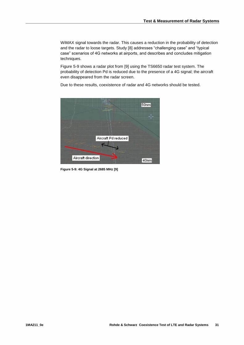
WiMAX signal towards the radar. This causes a reduction in the probability of detection
and the radar to loose targets. Study [8] addresses “challenging case” and “typical
case” scenarios of 4G networks at airports, and describes and concludes mitigation
techniques.
Figure 5-9 shows a radar plot from [9] using the TS6650 radar test system. The
probability of detection Pd is reduced due to the presence of a 4G signal; the aircraft
even disappeared from the radar screen.
Due to these results, coexistence of radar and 4G networks should be tested.
Figure 5-9: 4G Signal at 2685 MHz [9]

Mitigation Techniques
1MA211_0e Rohde & Schwarz Coexistence Test of LTE and Radar Systems 32
6 Mitigation Techniques
Different approaches can mitigate disturbances on radar and 4G base stations. One
approach is to reduce transmit power at the base station and radar. Also increasing
frequency separation or distance between the two services is a solution. However,
these two ideas reduce maximum range of the radar and coverage of the base station
and frequency selection may be impossible due technical restrictions. Avoiding to let
mobile service base station antennas point at towards S-Band radar is one approach to
mitigate. Also, the improvement of receiver selectivity, filtering of transmitter signals,
and reduction of unwanted spurious emissions on both sides allows coexistence.
The latter would be the most straightforward mitigation measure, both at the radar and
base station (BS) side. To avoid receiver saturation through inter-modulation and
blocking a filter can be placed on the radar's receiver before the Low Noise Amplifier
(LNA). At the BS side, a filter can be placed on the transmitter close to the antenna to
suppress the out-of-band (OOB) LTE emissions in the spurious domain. Furthermore,
a revision of the ETSI 3GPP technical specifications TS 136.101 (UE) and TS 136.104
(BS) is recommended. Currently, these standards impose flexible power levels for
Spurious Emissions in non-protected bands, while these levels are much more
stringent in the protected bands. Because the S-band (and also the L-band) is used for
security and safety services a more stringent maximum power level for Spurious
Emissions should be defined.
In any case, test and measurement of radar, LTE base stations and user equipment is
necessary to confirm spectral emission masks and prove robustness against other
coexisting signals.
Literature
1MA211_0e Rohde & Schwarz Coexistence Test of LTE and Radar Systems 33
7 Literature
[1] 3GPP TS36.521-1, Evolved Universal Terrestrial Radio Access (E-UTRA); User
Equipment (UE) conformance specification; Radio transmission and reception; Part 1
Conformance testing
[2] Rohde & Schwarz, Application Note 1SP16, Recording and Playing Back the GPS
RF Spectrum, retrieved from www.rohde-schwarz.de/appnote/1SP16, January 20,
2014
[3] International Telecommunication Union (ITU), Radio Regulations - Articles S5, S21
and S22 Appendix S4, WRC-95 Resolutions, WRC-95 Recommendations, Geneva
1996, ISBN 92-61-05171-5
[4] ITU Recommendation M.1464-1, Characteristics of radiolocation radars, and
characteristics and protection criteria for sharing studies for aeronautical
radionavigation and meteorological radars in the radiodetermination service operating
in the frequency band 2 700-2 900 MHz, July 2003
[5] R&S®TS6650 Interference Test System for ATC Radar Systems, retrieved from
www.rohde-schwarz-ad.com/docs/radartest/TS6650_bro_en.pdf, November 22, 2013
[6] realWireless, Ofcom, Final Report – Airport Deployment Study Ref MC/045, Version
1.5, 19th July 2011, retrieved from
www.ofcom.org.uk/static/spectrum/Airport_Deployment_Study.pdf, November 22, 2013
[7] Rohde & Schwarz, Application Note 1GP88, R&S ARB Toolbox Plus, retrieved from
www.rohde-schwarz.de/appnote/1GP88, January 20, 2014
[8] realWireless, Ofcom, Final Report – Airport Deployment Study Ref MC/045, Version
1.5, 19th July 2011, retrieved from
http://www.ofcom.org.uk/static/spectrum/Airport_Deployment_Study.pdf, November 22,
2013
[9] Cobham Technical Services, Final Report – Radiated Out-of-Band Watchmen
Radar Testing at RAF Honington, April 2009, retrieved from
http://stakeholders.ofcom.org.uk/binaries/spectrum/spectrum-awards/awards-in-
preparation/757738/589_Radiated_Out-of-Band_Wa1.pdf, November 22, 2013.
[10] ATC-Radar ASR-E, retrieved from
http://www.radartutorial.eu/19.kartei/karte206.de.html, March 20, 2014
[11] R&S Application Note 1GP96, CDM-Toolbox - Digital Modulation in a simple way,
retrieved from www.rohde-schwarz.com/appnote/1GP96, March 27, 2013

Ordering Information
1MA211_0e Rohde & Schwarz Coexistence Test of LTE and Radar Systems 34
8 Ordering Information
Designation Type Order No.
Vector Signal Generator R&S®SMW200A 1412.0000.02
Frequency Options, RF path A
100 kHz to 3 GHz
R&S®SMW-B103 1413.0004.02
Frequency Options, RF path A
100 kHz to 6 GHz
R&S®SMW-B106 1413.0104.02
Baseband Generator with ARB (64 Msample) and Digital
Modulation (realtime), 120 MHz RF bandwidth
R&S®SMW-B10 1413.1200.02
ARB Memory Extension to 512 Msample
R&S®SMW-K511 1413.6860.02
ARB Memory Extension to 1 Gsample
R&S®SMW-K512 1413.6919.02
Baseband Main Module, one I/Q path to RF
R&S®SMW-B13 1413.2807.02
Baseband Extension to 160 MHz RF bandwidth
R&S®SMW-K522 1413.6960.02
Interference Test System for ATC Radar Systems
R&S®TS6650 1519.6705.02
IQ recorder (SSD) with touch screen
R&S®IQR100 1513.4600K10
IQ recorder with touch screen (75 MSa/s) R&S®IQR100 1513.4600.10
SSD memory pack 1,9 TByte 400MByte/s R&S®IQR-B119F 1513.4723.19
IQR SW for configuring of the TSMW via LAN, incl. AGC (SL) R&S®IQR-K1 1513.4730.02
Software for controlling generators with IQR R&S®IQR-K2 1513.4752.02
Import/Export of I/Q and meta data files via USB and LAN R&S®IQR-K101 1517.5001.02
GPS Data recording on the IQR as meta data file R&S®IQR-K102 1517.5018.02
Graphical display of GPS data (IQR) R&S®IQR-K103 1517.5024.02
Ref. level controlled recording/replay of RF signals f. AGC R&S®IQR-K104 1517.5182.02
Power supply module, 10-30V DC, 200VA, BW2010 R&S®PSDC-B200 1513.4617.02
TSMW / IQR Case 3U, 19" for drive test, incl. integration R&S®IQR-CAS1 1513.4652.02
Carrier Trolley with inlet for IQR, TSMW and accessories R&S®IQR-Z6 1516.4360.02
TSMW High Performance Scanner R&S®TSMW 1503.3001K03

Ordering Information
1MA211_0e Rohde & Schwarz Coexistence Test of LTE and Radar Systems 35
TSMW High Performance Scanner R&S®TSMW 1503.3001.03
Digital I/Q Streaming Software Option for TSMW R&S®TSMW-K1 1503.3960.02
IQ Interface for R&S IQR R&S®TSMW-B1 1514.4004.02
TSMW AC power supply R&S®TSMW-Z1 1503.4608.02
CMW Wideband Radio Communication Tester
R&S®CMW500 1201.0002K50
R&S®CMW500 Basic Assembly
(mainframe),70MHz to 3.3GHz (sel.)
R&S®CMW-PS503 1208.7154.02
Baseband Meas. Unit, 1GByte memory, H100A (sel.)
R&S®CMW-S100A 1202.4701.02
Baseband Interconnection, flexible link, H550B (sel.)
R&S®CMW-S550B 1202.4801.03
RF Converter (TRX), H570B (sel.) R&S®CMW-S570B 1202.5008.03
RF Frontend, basic functionality, H590A (sel.)
R&S®CMW-S590A 1202.5108.02
CMW500 Frontpanel With Display/Keypad, H600B (sel.)
R&S®CMW-S600B 1201.0102.03
Baseband Generator, 1GByte memory, H110A (HW opt.)
R&S®CMW-B110A 1202.5508.02
Signaling Unit Wideband (SUW),for WCDMA/LTE,H300B (HW opt.)
R&S®CMW-B300B 1202.6304.03
Extra RF Converter (TRX), H570B (hw opt.)
R&S®CMW-B570B 1202.8659.03
Extra RF Frontend, basic functionality, H590A (hw opt.)
R&S®CMW-B590A 1202.8707.02
LTE FDD R8, TX measurement, uplink (SL)
R&S®CMW-KM500 1203.5501.02
LTE FDD R8, SISO, basic signaling (SL)
R&S®CMW-KS500 1203.6108.02
LTE R8, SISO, advanced signaling (SL)
R&S®CMW-KS510 1203.9859.02
Mini-UICC Test Card, supp. 3GPP
SIM/USIM/ISIM/CSIM (acc.)
R&S®CMW-Z04 1207.9901.02

About Rohde & Schwarz
Rohde & Schwarz is an independent group of
companies specializing in electronics. It is a leading
supplier of solutions in the fields of test and
measurement, broadcasting, radiomonitoring and
radiolocation, as well as secure communications.
Established more than 75 years ago, Rohde &
Schwarz has a global presence and a dedicated
service network in over 70 countries. Company
headquarters are in Munich, Germany.
Regional contact
Europe, Africa, Middle East +49 89 4129 12345 [email protected] North America 1-888-TEST-RSA (1-888-837-8772) [email protected] Latin America +1-410-910-7988 [email protected] Asia/Pacific +65 65 13 04 88 [email protected]
China +86-800-810-8228 /+86-400-650-5896 [email protected]
Environmental commitment
ı Energy-efficient products
ı Continuous improvement in environmental
sustainability
ı ISO 14001-certified environmental
management system
This and the supplied programs may only be used
subject to the conditions of use set forth in the
download area of the Rohde & Schwarz website.
R&S® is a registered trademark of Rohde & Schwarz GmbH & Co.
KG; Trade names are trademarks of the owners.
Rohde & Schwarz GmbH & Co. KG
Mühldorfstraße 15 | D - 81671 München
Phone + 49 89 4129 - 0 | Fax + 49 89 4129 – 13777
www.rohde-schwarz.com
PA
D-T
-M: 3573.7
380.0
2/0
2.0
0/C
I/1/E
N/