coercivity measurements on high permeability nickel-iron alloys using a modified npl vibrating coil...
TRANSCRIPT

Coercivity measurements on high permeability nickel-iron alloys using a modified NPL vibrating coil magnetometer
A.E.Drake T.M. Jasko
Indexing terms: Coercivity measurement, High permeability Ni-Fe alloys, Vibrating magnetometer
Abstract: A method for the rapid measurement of low coercive force materials (e.g. high permeability nickel-iron alloys) has been developed by modifying the NPL vibrating coil magnetometer to improve its sensitivity and by providing a magnetic shield to reduce the effects of the ambient magnetic field. A comparison of the results has been made with those obtained by the traditional ring method.
I Introduction
In response to an industrial need for a method to deter- mine the coercive force of soft magnetic materials used in relay manufacture, the NPL vibrating coil magne- tometer was developed and has been successfully used for many years [1, 21. The measurement of low values of coercivity made by the original magnetometer was limited by the sensitivity of the detector coil and the effects of ambient magnetic fields. A magnetic shielding system has been devised whereby the shield alone can be demagnetised after magnetising the test specimen to saturation. The results of a collaborative investigation to modify the magnetometer to extend its range down- wards from coercivities of 30 to 0.5AIm are reported.
2 Measurement system
The general arrangement of the vibrating coil magne- tometer is shown in Fig. 1. A test specimen in the form of a strip or bar is mounted at the centre of a solenoid, 0.7m in length and O.lm diameter, having a field to current constant of approximately 3 kA/m/A. The test specimen is magnetised to saturation by passing a steady current, of 15A, through the solenoid for approximately 2s. A steadily increasing low value cur- rent of opposite polarity is then passed through the solenoid and the output from a vibrating search coil around one end of the test specimen is observed. The search coil is connected to a detector tuned to the fre-
0 IEE, 1996 IEE Proceedings online no. 19960309 Paper received 5th January 1996 A.E. Drake is with the National Physical Laboratory, Teddington, Mid- dlesex, TWl 1 OLW, UK T.M. Jasko was formerly with Telcon Ltd, Napier Way, Crawley, Sussex, RHlO 2RB, UK
quency of vibration (20 Hz). When the magnetisation is reduced to zero, the output from this coil falls to zero. At this instant the value of current flowing in the sole- noid is recorded from which the applied magnetic field strength and hence the coercivity can be calculated.
nylon search Mumetal @ bush coil solenoid shield
test specimen specimen holder
Fig. 1 General arrangement of the NPL Vibrating cod magnetometer
Since the vibrating coil detects the point at which the magnetisation of the test specimen is reduced to zero, the device in fact measures the magnetisation coercive force HCp Usually, coercivity values are expressed in terms of the induction coercive force HcB. The relation- ship between the magnetisation coercive force and the induction coercive force is given by
where HcB and H,, are in Alm. Also, HCB = f f c J ( l - I/&) (1)
d p d B / p o d H (2) in the region B = 0. 'rhus, for magnetic materials with a high differential permeability in the region B = 0, the difference between the H,, and H,, is insignificant.
3 Modifications
The original magnetometer was modified by increasing the number of turns on the search coil to improve the sensitivity of the instrument at low values of coercivity. However, this increased the sensitivity to ambient mag- netic fields. These arose from: (ij direct pickup in the search coil of the stray field from the vibrator and (ii) the earth's magnetic field.
The unwanted alternating field arising from the vibrator was reduced to negligible proportions by extending the rod connecting the vibrator to the search coil. The effect of the earth's magnetic field was reduced to some extent by aligning the axis of the sole- noid east-west. It was also necessary to surround the solenoid with a cylindrical magnetic shield. For the purposes of the investigation, the magnetic shield was constructed from Mumetal@ strip (150mm wide x O.lOmm thick). It was made up of five overlapping
171 IEE Proc.-Sei. Mea.s. Technol., Vol. 143, No. 3, May 1996
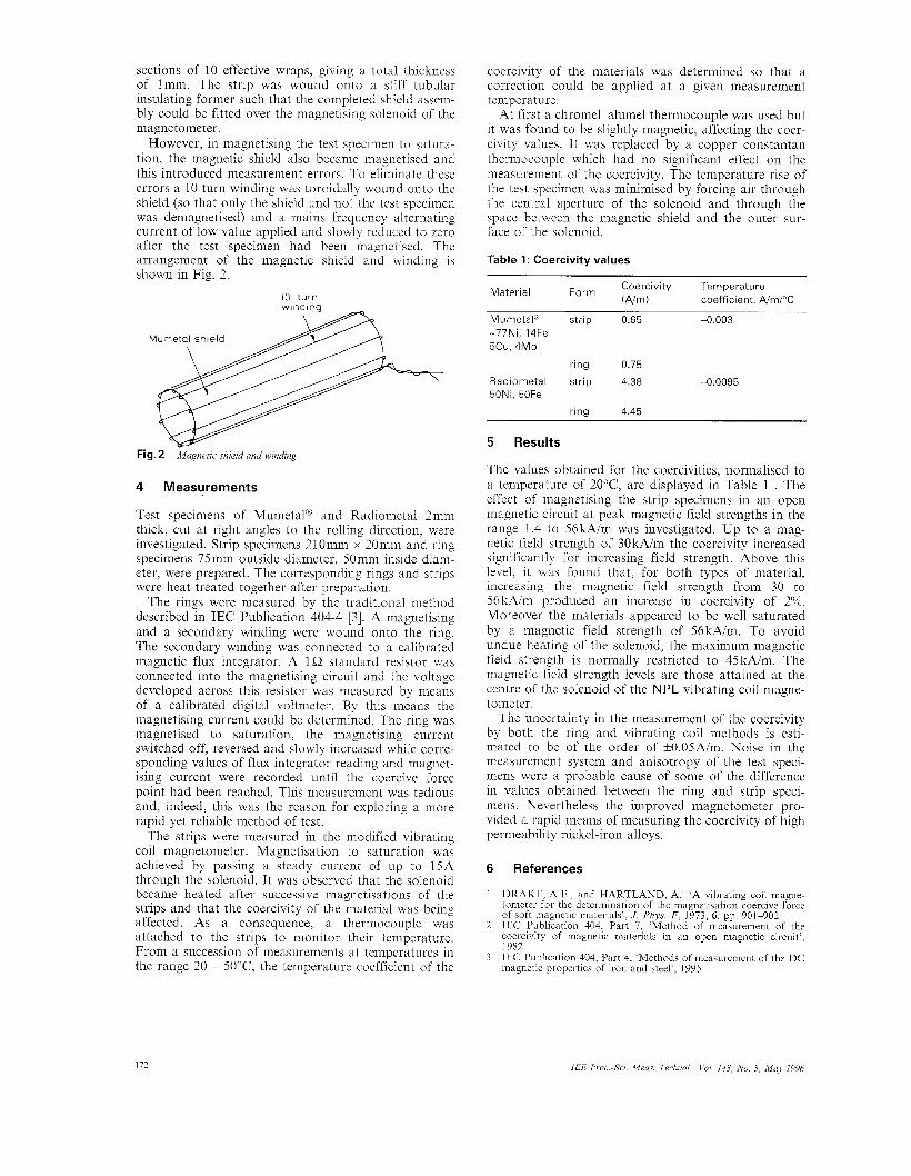
sections of 10 effective wraps, giving a total thickness of lmm. The strip was wound onto a stiff tubular insulating former such that the completed shield assem- bly could be fitted over the magnetising solenoid of the magnetometer.
However, in magnetising the test specimen to satura- tion, the magnetic shield also became magnetised and this introduced measurement errors. To eliminate these errors a 10 turn winding was toroidally wound onto the shield (so that only the shield and not the test specimen was demagnetised) and a mains frequency alternating current of low value applied and slowly reduced to zero after the test specimen had been magnetised. The arrangement of the magnetic shield and winding is shown in Fig. 2.
I O turn
Fig. 2 Mugnetic .shield and winding
4 Measurements
Test specimens of Mumetal@ and Radiometal 2mm thick, cut at right angles to the rolling direction, were investigated. Strip specimens 210mm x 20mm and ring specimens 75mm outside diameter, 50mm inside diam- eter, were prepared. The corresponding rings and strips were heat treated together after preparation.
The rings were measured by the traditional method described in IEC Publication 404-4 [3]. A magnetising and a secondary winding were wound onto the ring. The secondary winding was connected to a calibrated magnetic flux integrator. A 1Q standard resistor was connected into the magnetising circuit and the voltage developed across this resistor was measured by means of a calibrated digital voltmeter. By this means the magnetising current could be determined. The ring was magnetised to saturation, the magnetising current switched off, reversed and slowly increased while corre- sponding values of flux integrator reading and magnet- ising current were recorded until the coercive force point had been reached. This measurement was tedious and, indeed, this was the reason for exploring a more rapid yet reliable method of test.
The strips were measured in the modified vibrating coil magnetometer. Magnetisation to saturation was achieved by passing a steady current of up to l5A through the solenoid. It was observed that the solenoid became heated after successive magnetisations of the strips and that the coercivity of the material was being affected. As a consequence, a thermocouple was attached to the strips to monitor their temperature. From a succession of measurements at temperatures in the range 20 - 50°C, the temperature coefficient of the
coercivity of the materials was determined so that a correction could be applied at a given measurement temperature.
At first a chromel-alumel thermocouple was used but it was found to be slightly magnetic, affecting the coer- civity values. It was replaced by a copper-constantan thermocouple which had no significant effect on the measurement of the coercivity. The temperature rise of the test specimen was minimised by forcing air through the central aperture of the solenoid and through the space between the magnetic shield and the outer sur- face of the solenoid.
Table 1: Coercivity values
Coercivity Temperature (Aim) coefficient, A/rnpC Material Form
Mumetal" strip 0.65 -0.003 -77Ni, 14Fe 5cU, 4MO
ring 0.75
Radiometal strip 4.38 -0.0095 50Ni, 50Fe
rina 4.45
5 Results
The values obtained for the coercivities, normalised to a temperature of 20°C, are displayed in Table 1 . The effect of magnetising the strip specimens in an open magnetic circuit at peak magnetic field strengths in the range 1.4 to 56kAim was investigated. Up to a mag- netic field strength of 30 kA/m the coercivity increased significantly for increasing field strength. Above this level, it was found that, for both types of material, increasing the magnetic field strength from 30 to 56kAlm produced an increase in coercivity of 2%. Moreover the materials appeared to be well saturated by a magnetic field strength of 56kA/m. To avoid undue heating of the solenoid, the maximum magnetic field strength is normally restricted to 45 kA/m. The magnetic field strength levels are those attained at the centre of the solenoid of the NPL vibrating coil magne- tometer.
The uncertainty in the measurement o f the coercivity by both the ring and vibrating coil methods is esti- mated to be of the order of f0.05A/m. Noise in the measurement system and anisotropy of the test speci- mens were a probable cause of some of the difference in values obtained between the ring and strip speci- mens. Nevertheless the improved magnetometer pro- vided a rapid means of measuring the coercivity of high permeability nickel-iron alloys.
6 References
1 DRAKE, A.E., and HARTLAND, A.: 'A vibrating coil magne- tometer for the determination of the magnetisation coercive lorce of soft magnetic materials', J. Phys. E, 1973, 6, pp. 901-902 IEC Publication 404, Part 7, 'Method of measurement of the coercivity of magnetic materials in an open magnetic circuit', 1982 IEC Publication 404, Part 4, 'Methods of measurement of the DC magnetic properties of iron and steel', 1995
2
3
172 IEE Proc.-Sci Meus. Teciznol., Vol. 143, No. 3, M u y 1996