co2 capture utilization and sequestration (ccus)
TRANSCRIPT
Answers for energy. Copyright © Siemens AG 2015 All rights reserved.
CO2 Capture Utilization and Sequestration (CCUS) with Siemens’ PostCapTM Technology
Siemens AG – Division Power and Gas
Unrestricted © Siemens AG 2015 All rights reserved. PG MOP CCS
Page 2
Content
Market Development
CCUS within Siemens
Technology Leadership with Siemens PostCapTM
Engineering Capabilities and References
Business Models and Implementation Strategy
Page 2 Unrestricted
Unrestricted © Siemens AG 2015 All rights reserved. PG MOP CCS
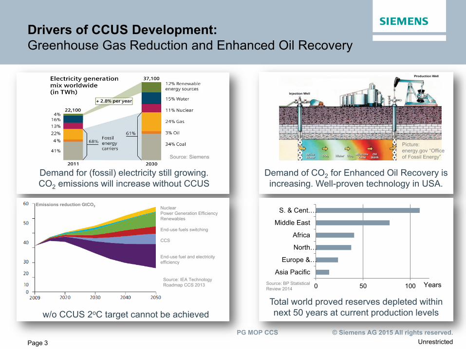
Drivers of CCUS Development: Greenhouse Gas Reduction and Enhanced Oil Recovery
Demand for (fossil) electricity still growing. CO2 emissions will increase without CCUS
Demand of CO2 for Enhanced Oil Recovery is increasing. Well-proven technology in USA.
Source: Siemens
Picture: energy.gov “Office of Fossil Energy”
Page 3
Page 3
Welche Ziele?
w/o CCUS 2oC target cannot be achieved
Nuclear Power Generation Efficiency Renewables End-use fuels switching CCS End-use fuel and electricity efficiency
Source: IEA Technology Roadmap CCS 2013
Emissions reduction GtCO2
0 50 100
Asia Pacific
Europe &…
North…
Africa
Middle East
S. & Cent.…
Years
Total world proved reserves depleted within next 50 years at current production levels
Source: BP Statistical Review 2014
Unrestricted © Siemens AG 2015 All rights reserved. PG MOP CCS
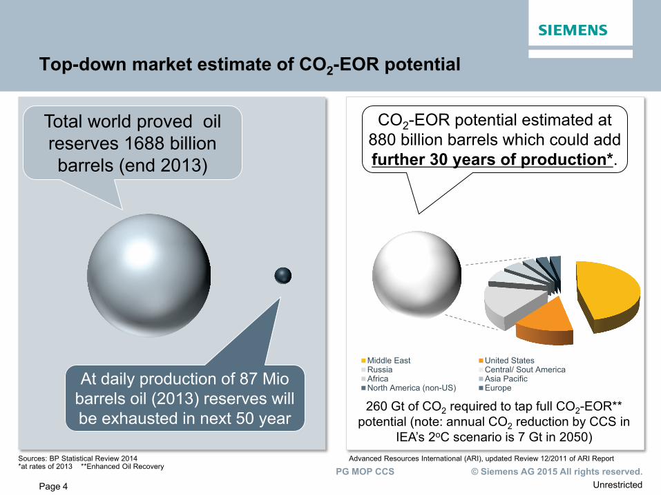
Total world proved oil reserves 1688 billion barrels (end 2013)
Page 4
Top-down market estimate of CO2-EOR potential
At daily production of 87 Mio barrels oil (2013) reserves will be exhausted in next 50 year
Sources: BP Statistical Review 2014 Advanced Resources International (ARI), updated Review 12/2011 of ARI Report *at rates of 2013 **Enhanced Oil Recovery
CO2-EOR potential estimated at 880 billion barrels which could add further 30 years of production*.
Middle East United StatesRussia Central/ Sout AmericaAfrica Asia PacificNorth America (non-US) Europe
260 Gt of CO2 required to tap full CO2-EOR** potential (note: annual CO2 reduction by CCS in
IEA’s 2oC scenario is 7 Gt in 2050)
Unrestricted © Siemens AG 2015 All rights reserved. PG MOP CCS
Page 5
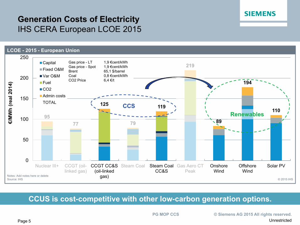
Generation Costs of Electricity IHS CERA European LCOE 2015
CCUS is cost-competitive with other low-carbon generation options.
95 77
125
79
119
219
89
194
110
0
50
100
150
200
250
Nuclear III+ CCGT (oil-linked gas)
CCGT CC&S(oil-linked
gas)
Steam Coal Steam CoalCC&S
Gas Aero CTPeak
OnshoreWind
OffshoreWind
Solar PV
CapitalFixed O&MVar O&MFuelCO2Admin costsTOTAL
LCOE - 2015 - European Union
© 2015 IHS
€/M
Wh
(rea
l 201
4)
Notes: Add notes here or delete Source: IHS
Gas price - LT 1,9 €cent/kWh Gas price - Spot 1,9 €cent/kWh Brent 65,1 $/barrel Coal 0,8 €cent/kWh CO2 Price 6,4 €/t
CCS Renewables
Unrestricted © Siemens AG 2015 All rights reserved. PG MOP CCS
Page 6
Content
Market Development
CCUS within Siemens
Technology Leadership with Siemens PostCapTM
Engineering Capabilities and References
Business Models and Implementation Strategy
Page 6 © Siemens AG 2013 All rights reserved.
Unrestricted © Siemens AG 2015 All rights reserved. PG MOP CCS
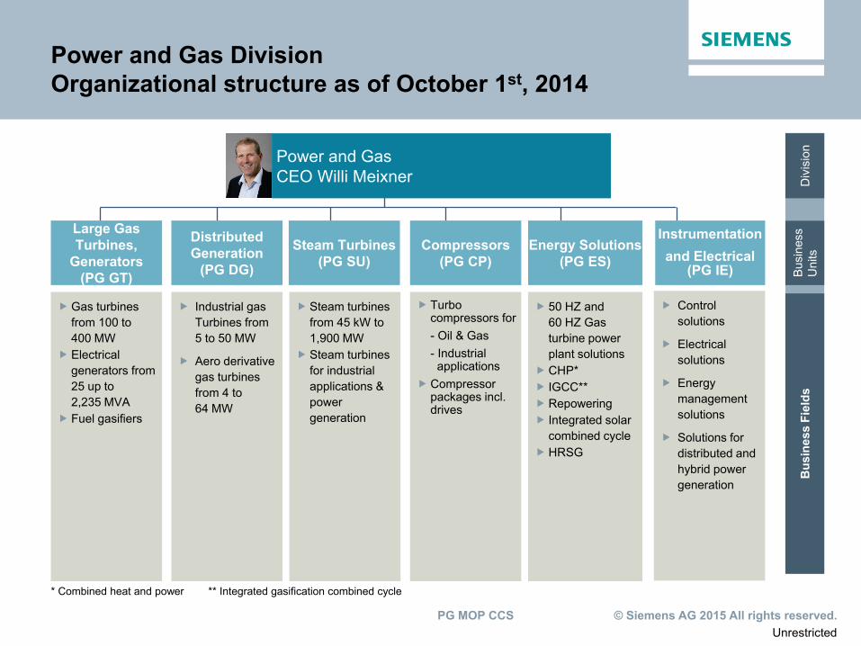
Power and Gas Division Organizational structure as of October 1st, 2014
Div
isio
n Bu
sine
ss
Uni
ts
Bus
ines
s Fi
elds
* Combined heat and power ** Integrated gasification combined cycle
Turbo compressors for - Oil & Gas - Industrial applications
Compressor packages incl. drives
Gas turbines from 100 to 400 MW
Electrical generators from 25 up to 2,235 MVA
Fuel gasifiers
Industrial gas Turbines from 5 to 50 MW
Aero derivative gas turbines from 4 to 64 MW
Steam turbines from 45 kW to 1,900 MW
Steam turbines for industrial applications & power generation
50 HZ and 60 HZ Gas turbine power plant solutions
CHP* IGCC** Repowering Integrated solar
combined cycle HRSG
Instrumentation and Electrical
(PG IE)
Compressors (PG CP)
Large Gas Turbines,
Generators (PG GT)
Distributed Generation
(PG DG)
Steam Turbines (PG SU)
Energy Solutions (PG ES)
Control solutions
Electrical solutions
Energy management solutions
Solutions for distributed and hybrid power generation
Power and Gas CEO Willi Meixner
Unrestricted © Siemens AG 2015 All rights reserved. PG MOP CCS
Page 8
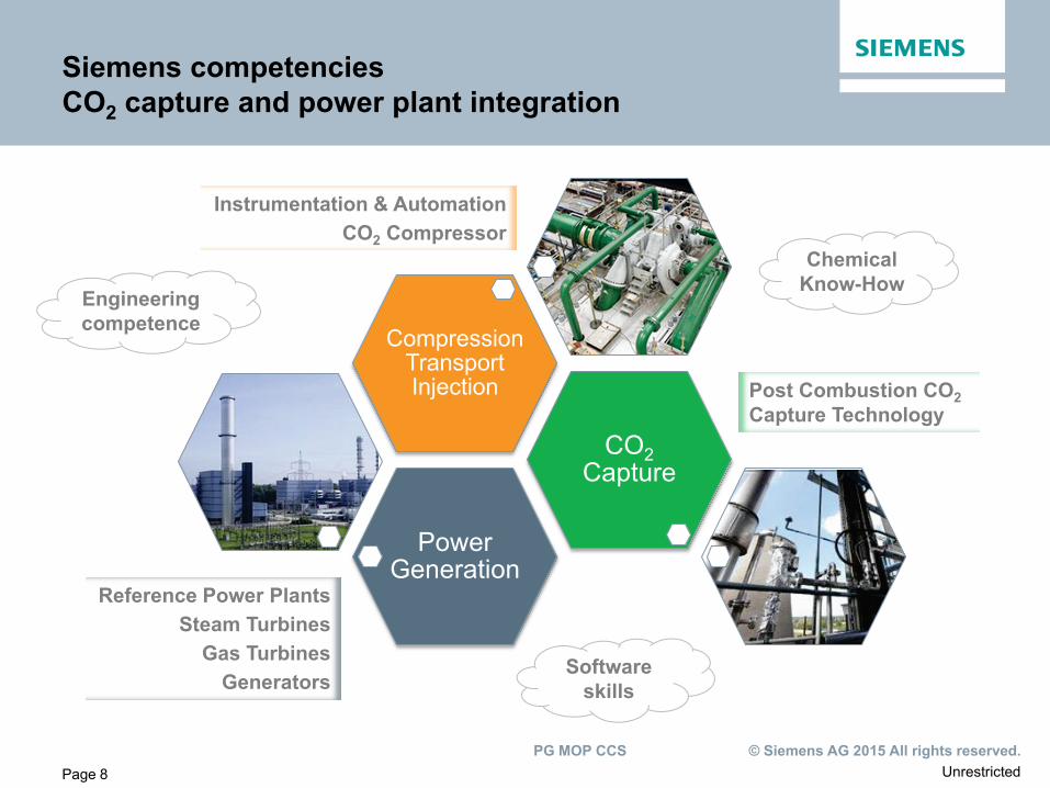
Siemens competencies CO2 capture and power plant integration
Power Generation
CO2 Capture
Compression Transport Injection
Reference Power Plants Steam Turbines
Gas Turbines Generators
Post Combustion CO2 Capture Technology
Instrumentation & Automation CO2 Compressor
Engineering competence
Software skills
Chemical Know-How
Unrestricted © Siemens AG 2015 All rights reserved. PG MOP CCS
Page 9
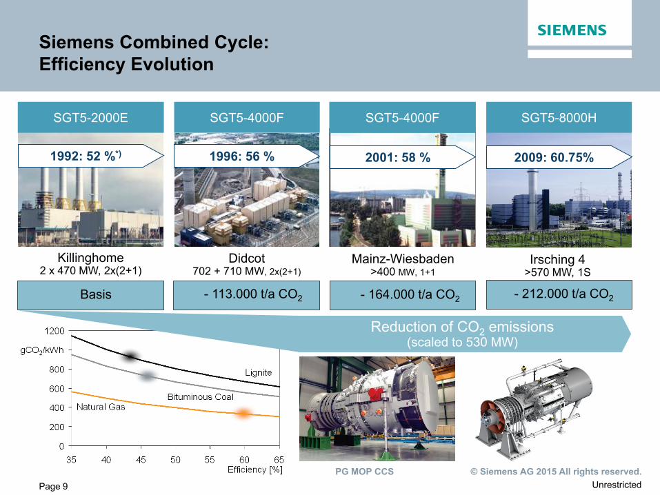
Siemens Combined Cycle: Efficiency Evolution
SGT5-8000H
2009: 60.75%
Mainz-Wiesbaden >400 MW, 1+1
SGT5-4000F
2001: 58 %
Didcot 702 + 710 MW, 2x(2+1)
SGT5-4000F
1996: 56 %
Killinghome 2 x 470 MW, 2x(2+1)
SGT5-2000E
1992: 52 %*)
- 212.000 t/a CO2 Basis - 164.000 t/a CO2 - 113.000 t/a CO2
Reduction of CO2 emissions (scaled to 530 MW)
Irsching 4 >570 MW, 1S
Unrestricted © Siemens AG 2015 All rights reserved. PG MOP CCS
Page 10
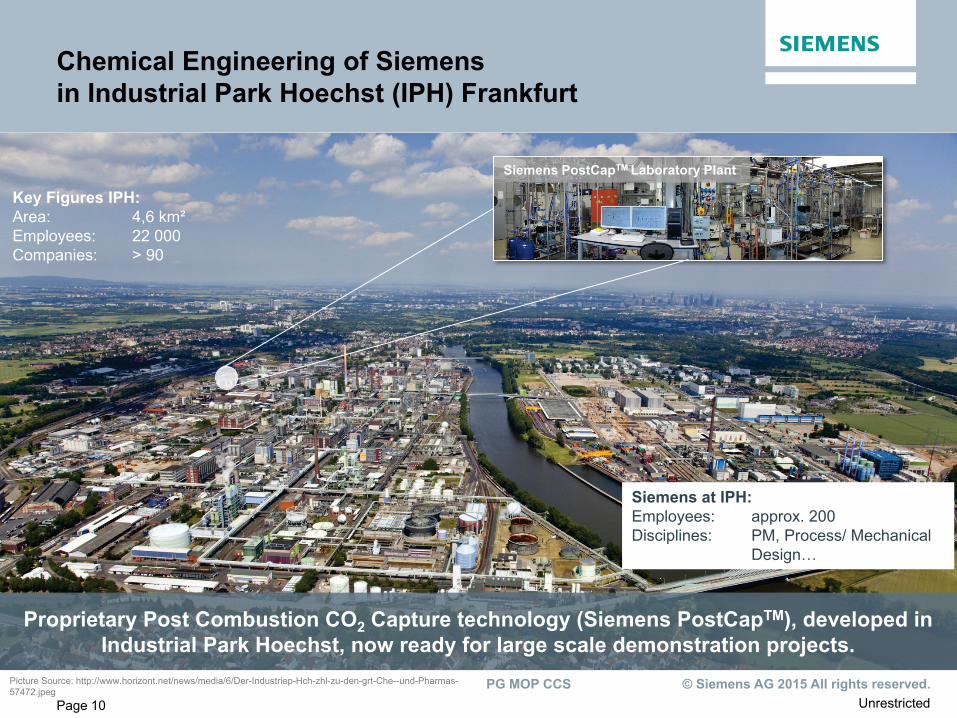
Chemical Engineering of Siemens in Industrial Park Hoechst (IPH) Frankfurt
Proprietary Post Combustion CO2 Capture technology (Siemens PostCapTM), developed in Industrial Park Hoechst, now ready for large scale demonstration projects.
Key Figures IPH: Area: 4,6 km² Employees: 22 000 Companies: > 90
Picture Source: http://www.horizont.net/news/media/6/Der-Industriep-Hch-zhl-zu-den-grt-Che--und-Pharmas-57472.jpeg
Siemens at IPH: Employees: approx. 200 Disciplines: PM, Process/ Mechanical Design…
Siemens PostCapTM Laboratory Plant
Unrestricted © Siemens AG 2015 All rights reserved. PG MOP CCS
Page 11
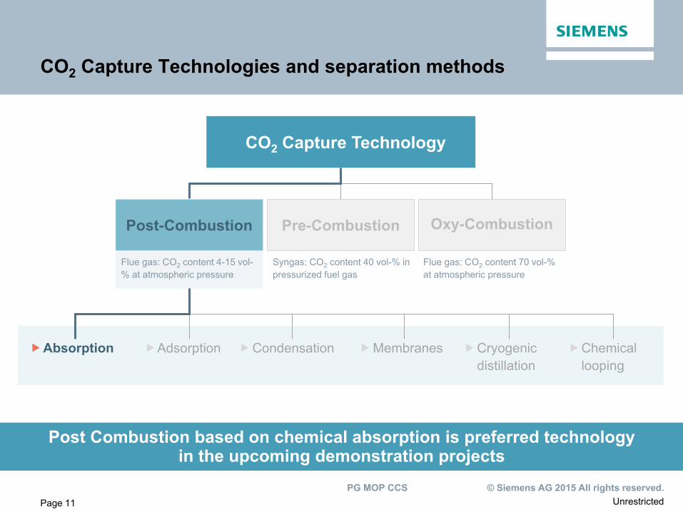
Flue gas: CO2 content 4-15 vol-% at atmospheric pressure
Syngas: CO2 content 40 vol-% in pressurized fuel gas
Flue gas: CO2 content 70 vol-% at atmospheric pressure
CO2 Capture Technologies and separation methods
CO2 Capture Technology
Post-Combustion Pre-Combustion Oxy-Combustion
Absorption Adsorption Cryogenic distillation
Membranes Condensation Chemical looping
Post Combustion based on chemical absorption is preferred technology in the upcoming demonstration projects
Unrestricted © Siemens AG 2015 All rights reserved. PG MOP CCS
Page 12
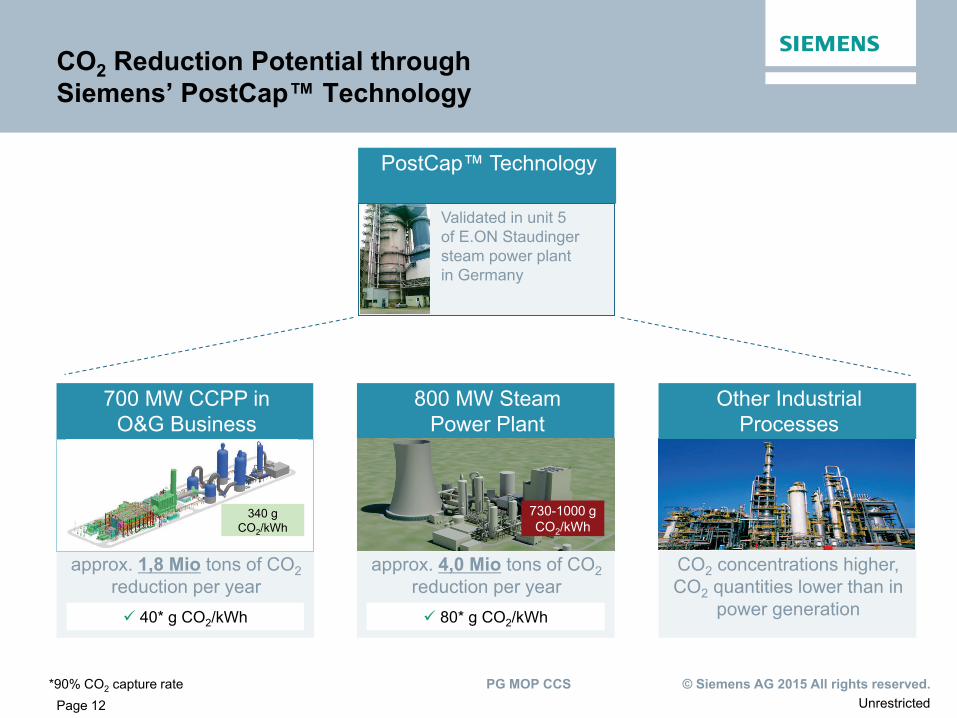
PostCap™ Technology
Validated in unit 5 of E.ON Staudinger steam power plant in Germany
approx. 4,0 Mio tons of CO2 reduction per year
CO2 concentrations higher, CO2 quantities lower than in
power generation
approx. 1,8 Mio tons of CO2 reduction per year
*90% CO2 capture rate
80* g CO2/kWh 40* g CO2/kWh
700 MW CCPP in O&G Business
340 g CO2/kWh
800 MW Steam Power Plant
730-1000 g CO2/kWh
Other Industrial Processes
CO2 Reduction Potential through Siemens’ PostCap™ Technology
Unrestricted © Siemens AG 2015 All rights reserved. PG MOP CCS
Page 13
Content
Market Development
CCUS within Siemens
Technology Leadership with Siemens PostCapTM
Engineering Capabilities and References
Business Models and Implementation Strategy
Page 13 Unrestricted
Unrestricted © Siemens AG 2015 All rights reserved. PG MOP CCS
Page 14
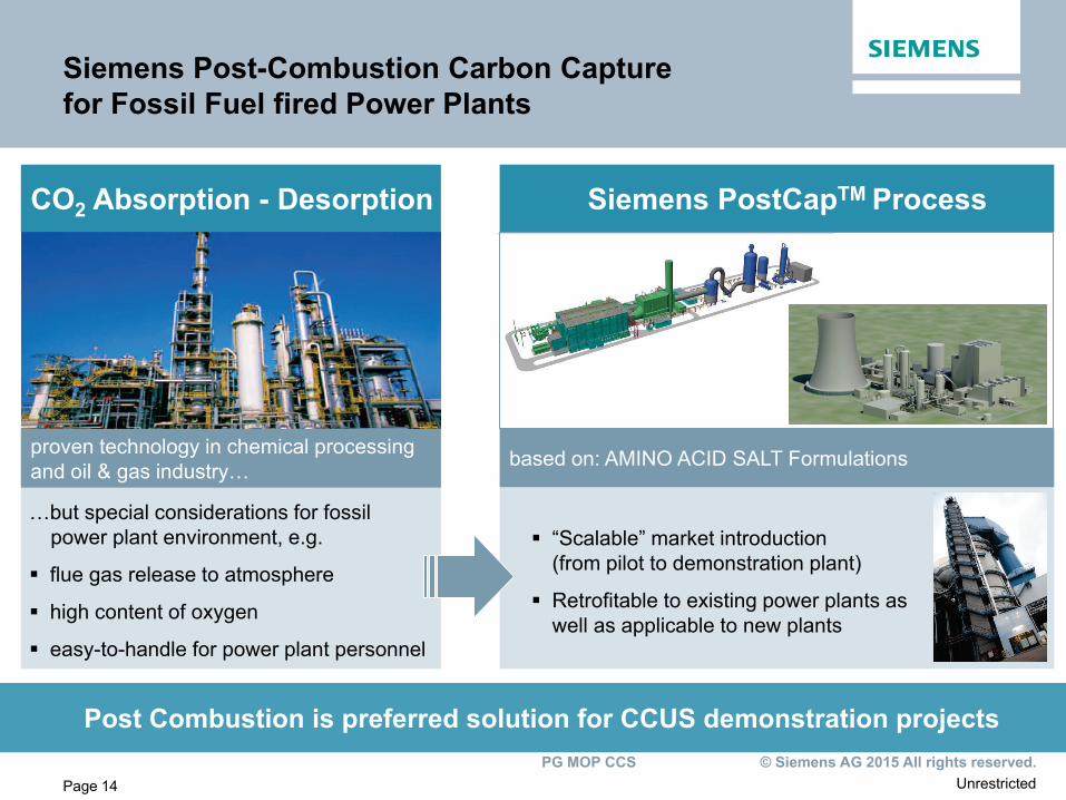
Siemens Post-Combustion Carbon Capture for Fossil Fuel fired Power Plants
Post Combustion is preferred solution for CCUS demonstration projects
CO2 Absorption - Desorption
proven technology in chemical processing and oil & gas industry…
…but special considerations for fossil power plant environment, e.g.
flue gas release to atmosphere
high content of oxygen
easy-to-handle for power plant personnel
Siemens PostCapTM Process
based on: AMINO ACID SALT Formulations
“Scalable” market introduction (from pilot to demonstration plant)
Retrofitable to existing power plants as well as applicable to new plants
Unrestricted © Siemens AG 2015 All rights reserved. PG MOP CCS
Page 15
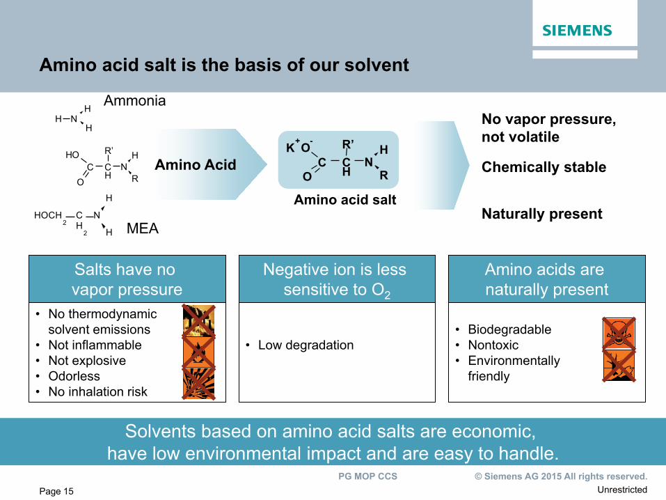
Amino acid salt
C H
N C H
R
R’ O
O
K + -
Amino Acid C H
N C H
R
R’ O H
O
N H
H H
Negative ion is less sensitive to O2
• Low degradation
Salts have no vapor pressure
• No thermodynamic solvent emissions
• Not inflammable • Not explosive • Odorless • No inhalation risk
Amino acids are naturally present
• Biodegradable • Nontoxic • Environmentally friendly
C H
2
N H O C H 2
H
H
Amino acid salt is the basis of our solvent
Solvents based on amino acid salts are economic, have low environmental impact and are easy to handle.
No vapor pressure, not volatile
Chemically stable
Naturally present
Ammonia
MEA
Unrestricted © Siemens AG 2015 All rights reserved. PG MOP CCS
Page 16
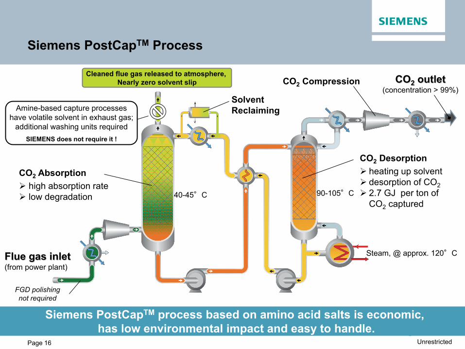
Siemens PostCapTM Process
40-45°C 90-105°C
CO2 outlet (concentration > 99%)
Steam, @ approx. 120°C Flue gas inlet (from power plant)
CO2 Absorption high absorption rate low degradation
Cleaned flue gas released to atmosphere, Nearly zero solvent slip
CO2 Desorption heating up solvent desorption of CO2 2.7 GJ per ton of
CO2 captured
CO2 Compression
Siemens PostCapTM process based on amino acid salts is economic, has low environmental impact and easy to handle.
Amine-based capture processes have volatile solvent in exhaust gas;
additional washing units required SIEMENS does not require it !
Solvent Reclaiming
FGD polishing not required
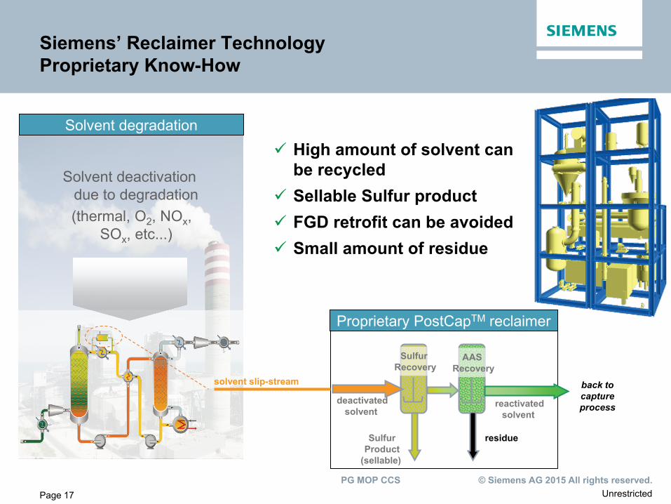
Unrestricted © Siemens AG 2015 All rights reserved. PG MOP CCS
Page 17
Sulfur Recovery
deactivated solvent
AAS Recovery
residue
reactivated solvent
Proprietary PostCapTM reclaimer
High amount of solvent can be recycled
Sellable Sulfur product FGD retrofit can be avoided Small amount of residue
Siemens’ Reclaimer Technology Proprietary Know-How
Sulfur Product
(sellable)
Solvent degradation
Solvent deactivation due to degradation
(thermal, O2, NOx, SOx, etc...)
back to capture process
solvent slip-stream
Unrestricted © Siemens AG 2015 All rights reserved. PG MOP CCS
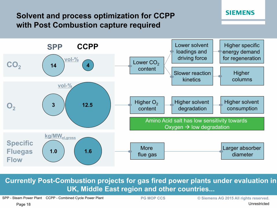
Page 18
Solvent and process optimization for CCPP with Post Combustion capture required
Lower CO2 content
Higher specific energy demand for regeneration
Higher columns
Lower solvent loadings and driving force
Slower reaction kinetics
Currently Post-Combustion projects for gas fired power plants under evaluation in UK, Middle East region and other countries...
14 4
SPP CCPP
CO2
Higher O2 content
Higher solvent degradation
Higher solvent consumption 3 12.5 O2
More flue gas
Larger absorber diameter 1.0 1.6
Specific Fluegas Flow
vol-%
vol-%
kg/MWel,gross
Amino Acid salt has low sensitivity towards Oxygen low degradation
SPP - Steam Power Plant CCPP - Combined Cycle Power Plant
Unrestricted © Siemens AG 2015 All rights reserved. PG MOP CCS
Page 19
Content
Market Development
CCUS within Siemens
Technology Leadership with Siemens PostCapTM
Engineering Capabilities and References
Business Models and Implementation Strategy
Page 19 Unrestricted © Siemens AG 2013 All rights reserved.
Unrestricted © Siemens AG 2015 All rights reserved. PG MOP CCS
Page 20
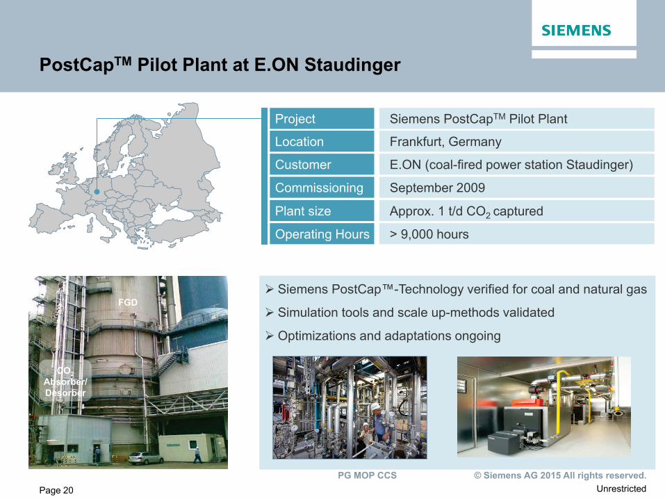
PostCapTM Pilot Plant at E.ON Staudinger
Project Siemens PostCapTM Pilot Plant
Location Frankfurt, Germany
Customer E.ON (coal-fired power station Staudinger)
Commissioning September 2009
Plant size Approx. 1 t/d CO2 captured
Siemens PostCap™-Technology verified for coal and natural gas
Simulation tools and scale up-methods validated
Optimizations and adaptations ongoing
Operating Hours > 9,000 hours
CO2 Absorber/ Desorber
FGD
Unrestricted © Siemens AG 2015 All rights reserved. PG MOP CCS
Page 21
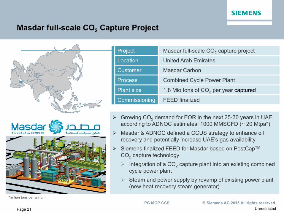
Masdar full-scale CO2 Capture Project
Project Masdar full-scale CO2 capture project
Location United Arab Emirates
Customer Masdar Carbon
Process Combined Cycle Power Plant
Plant size 1.8 Mio tons of CO2 per year captured
Growing CO2 demand for EOR in the next 25-30 years in UAE, according to ADNOC estimates: 1000 MMSCFD (~ 20 Mtpa*)
Masdar & ADNOC defined a CCUS strategy to enhance oil recovery and potentially increase UAE’s gas availability
Siemens finalized FEED for Masdar based on PostCapTM CO2 capture technology Integration of a CO2 capture plant into an existing combined
cycle power plant Steam and power supply by revamp of existing power plant
(new heat recovery steam generator)
Commissioning FEED finalized
*million tons per annum
Unrestricted © Siemens AG 2015 All rights reserved. PG MOP CCS
Page 22
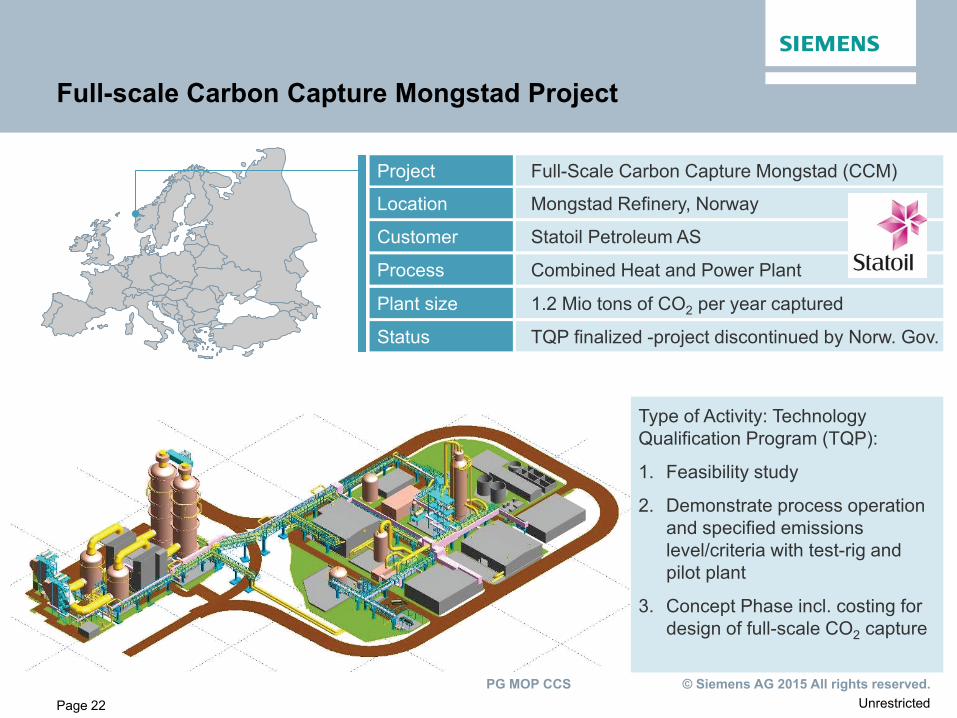
Full-scale Carbon Capture Mongstad Project
Project Full-Scale Carbon Capture Mongstad (CCM)
Location Mongstad Refinery, Norway
Customer Statoil Petroleum AS
Process Combined Heat and Power Plant
Plant size 1.2 Mio tons of CO2 per year captured
Status TQP finalized -project discontinued by Norw. Gov.
Type of Activity: Technology Qualification Program (TQP):
1. Feasibility study
2. Demonstrate process operation and specified emissions level/criteria with test-rig and pilot plant
3. Concept Phase incl. costing for design of full-scale CO2 capture
Unrestricted © Siemens AG 2015 All rights reserved. PG MOP CCS
Page 23
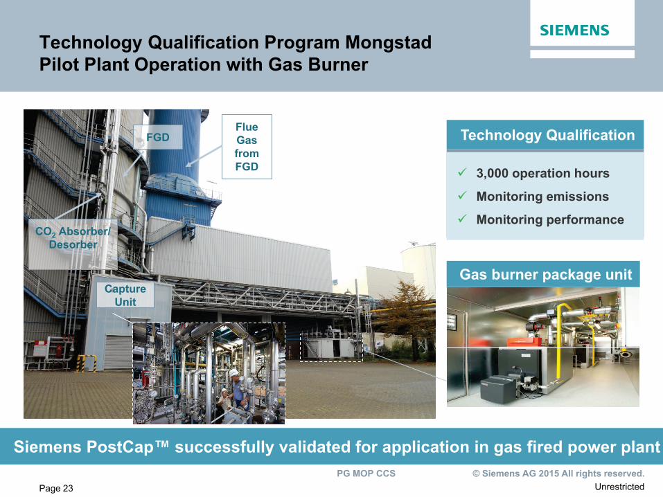
Technology Qualification Program Mongstad Pilot Plant Operation with Gas Burner
Technology Qualification
3,000 operation hours
Monitoring emissions
Monitoring performance
Gas burner package unit
Siemens PostCap™ successfully validated for application in gas fired power plant
CO2 Absorber/ Desorber
FGD
Capture Unit
Flue Gas from FGD
Unrestricted © Siemens AG 2015 All rights reserved. PG MOP CCS
Page 24
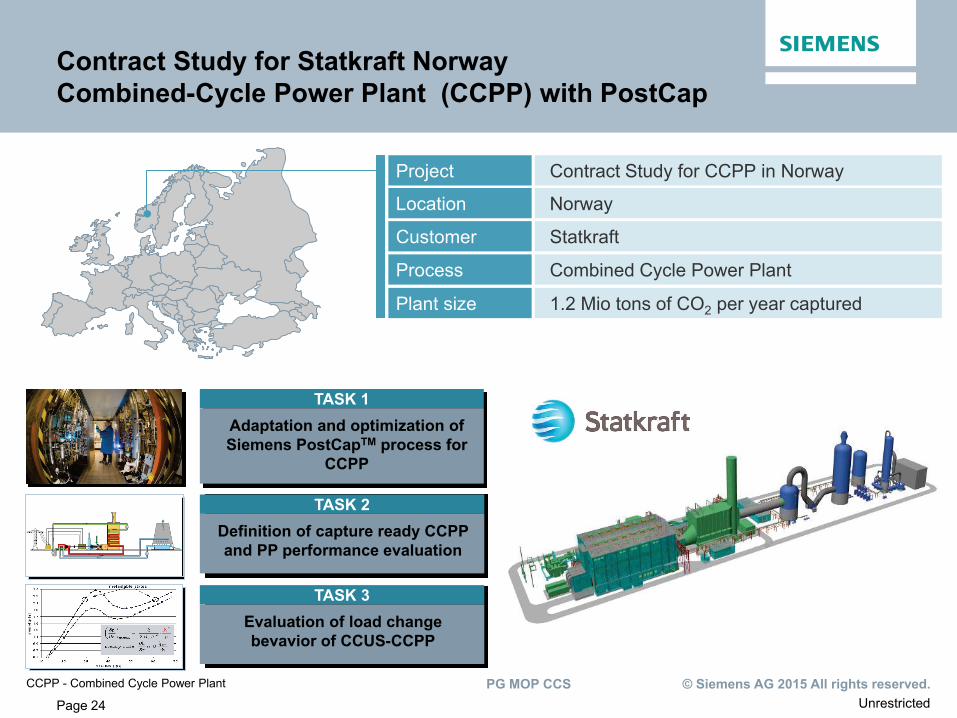
Contract Study for Statkraft Norway Combined-Cycle Power Plant (CCPP) with PostCap
Project Contract Study for CCPP in Norway
Location Norway
Customer Statkraft
Process Combined Cycle Power Plant
Plant size 1.2 Mio tons of CO2 per year captured
TASK 1 Adaptation and optimization of Siemens PostCapTM process for
CCPP
TASK 2 Definition of capture ready CCPP and PP performance evaluation
TASK 3 Evaluation of load change bevavior of CCUS-CCPP
CCPP - Combined Cycle Power Plant
Unrestricted © Siemens AG 2015 All rights reserved. PG MOP CCS
Page 25
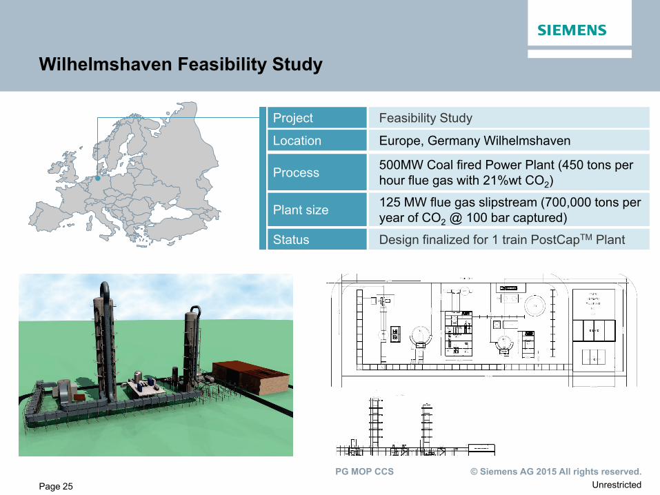
Wilhelmshaven Feasibility Study
Project Feasibility Study
Location Europe, Germany Wilhelmshaven
Process 500MW Coal fired Power Plant (450 tons per hour flue gas with 21%wt CO2)
Plant size 125 MW flue gas slipstream (700,000 tons per year of CO2 @ 100 bar captured)
Status Design finalized for 1 train PostCapTM Plant
Unrestricted © Siemens AG 2015 All rights reserved. PG MOP CCS
Page 26
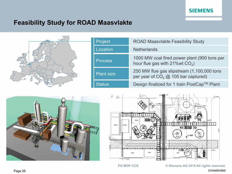
Feasibility Study for ROAD Maasvlakte
Project ROAD Maasvlakte Feasibility Study
Location Netherlands
Process 1000 MW coal fired power plant (900 tons per hour flue gas with 21%wt CO2)
Plant size 250 MW flue gas slipstream (1,100,000 tons per year of CO2 @ 100 bar captured)
Status Design finalized for 1 train PostCapTM Plant
Unrestricted © Siemens AG 2015 All rights reserved. PG MOP CCS
Page 27
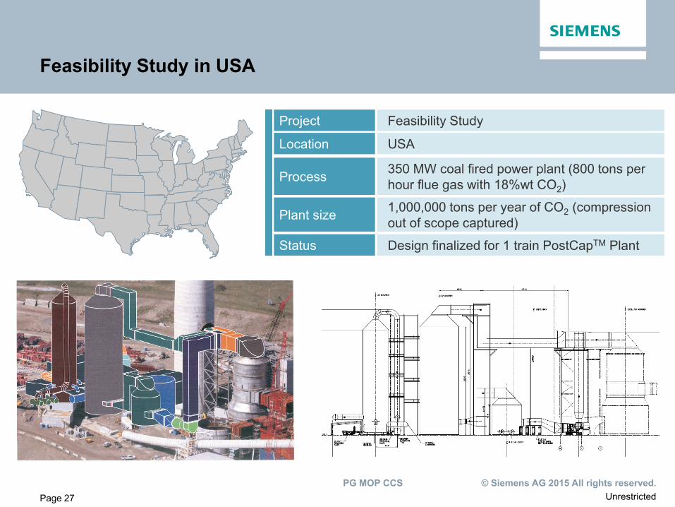
Feasibility Study in USA
Project Feasibility Study
Location USA
Process 350 MW coal fired power plant (800 tons per hour flue gas with 18%wt CO2)
Plant size 1,000,000 tons per year of CO2 (compression out of scope captured)
Status Design finalized for 1 train PostCapTM Plant
Unrestricted © Siemens AG 2015 All rights reserved. PG MOP CCS
Page 28
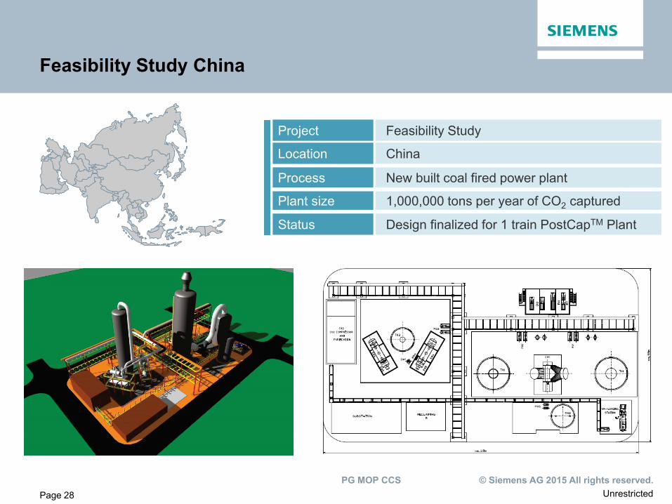
Feasibility Study China
Project Feasibility Study
Location China
Process New built coal fired power plant
Plant size 1,000,000 tons per year of CO2 captured
Status Design finalized for 1 train PostCapTM Plant
Unrestricted © Siemens AG 2015 All rights reserved. PG MOP CCS
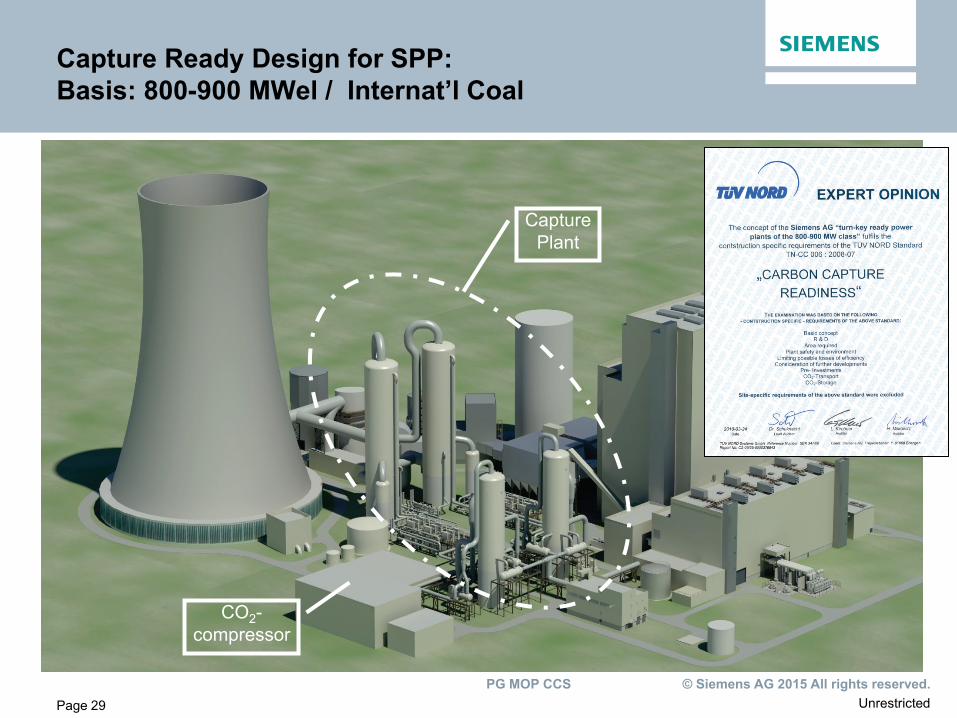
Page 29
Capture Ready Design for SPP: Basis: 800-900 MWel / Internat’l Coal
Capture Plant
CO2- compressor
Unrestricted © Siemens AG 2015 All rights reserved. PG MOP CCS
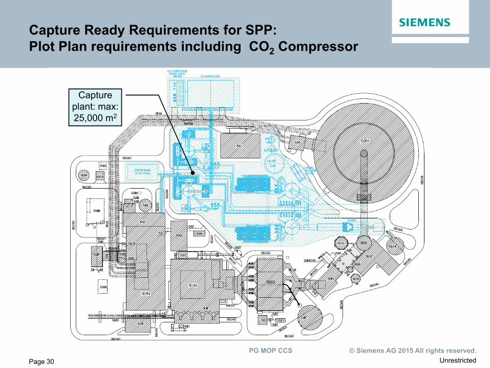
Page 30
Capture plant: max: 25,000 m2
Capture Ready Requirements for SPP: Plot Plan requirements including CO2 Compressor
Unrestricted © Siemens AG 2015 All rights reserved. PG MOP CCS
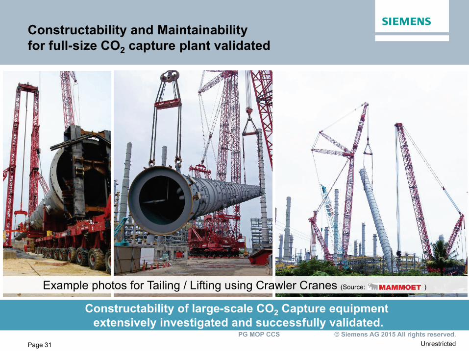
Page 31
Constructability and Maintainability for full-size CO2 capture plant validated
Constructability of large-scale CO2 Capture equipment extensively investigated and successfully validated.
Example photos for Tailing / Lifting using Crawler Cranes (Source: )
Unrestricted © Siemens AG 2015 All rights reserved. PG MOP CCS
Page 32
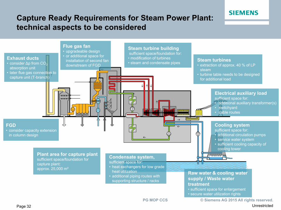
FGD • consider capacity extension
in column design
Exhaust ducts • consider Δp from CO2
absorption unit • later flue gas connection to
capture unit (T-branch)
Flue gas fan • upgradeable design • or additional space for
installation of second fan downstream of FGD
Steam turbines • extraction of approx. 40 % of LP
steam • turbine table needs to be designed
for additional load
Steam turbine building sufficient space/foundation for: • modification of turbines • steam and condensate pipes
Electrical auxiliary load sufficient space for: • additional auxiliary transformer(s) • switchyard • cable routes
Condensate system, sufficient space for: • heat exchangers for low grade
heat utilization • additional piping routes with
supporting structure / racks
Cooling system sufficient space for: • additional circulation pumps • service water system • sufficient cooling capacity of
cooling tower
Raw water & cooling water supply / Waste water treatment • sufficient space for enlargement • secure water utilization rights
Plant area for capture plant sufficient space/foundation for capture plant: approx. 25,000 m²
Capture Ready Requirements for Steam Power Plant: technical aspects to be considered
Unrestricted © Siemens AG 2015 All rights reserved. PG MOP CCS
Page 33
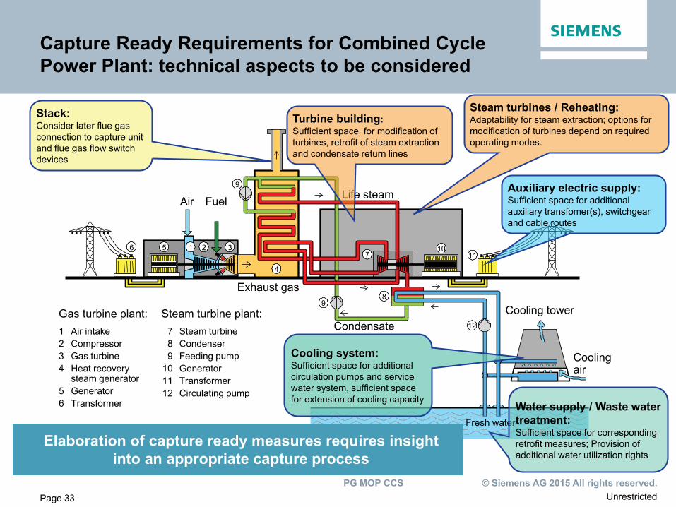
Exhaust gas
Life steam
Condensate
4
9 8
10
Cooling tower
Cooling air
6 5 1 2 3
Air Fuel
Gas turbine plant:
11
12
7
9
Fresh water
1 Air intake 2 Compressor 3 Gas turbine 4 Heat recovery steam generator 5 Generator 6 Transformer
Steam turbine plant: 7 Steam turbine 8 Condenser 9 Feeding pump 10 Generator 11 Transformer 12 Circulating pump
Capture Ready Requirements for Combined Cycle Power Plant: technical aspects to be considered
Steam turbines / Reheating: Adaptability for steam extraction; options for modification of turbines depend on required operating modes.
Turbine building: Sufficient space for modification of turbines, retrofit of steam extraction and condensate return lines
Auxiliary electric supply: Sufficient space for additional auxiliary transfomer(s), switchgear and cable routes
Cooling system: Sufficient space for additional circulation pumps and service water system, sufficient space for extension of cooling capacity
Water supply / Waste water treatment: Sufficient space for corresponding retrofit measures; Provision of additional water utilization rights
Stack: Consider later flue gas connection to capture unit and flue gas flow switch devices
Elaboration of capture ready measures requires insight into an appropriate capture process
Unrestricted © Siemens AG 2015 All rights reserved. PG MOP CCS
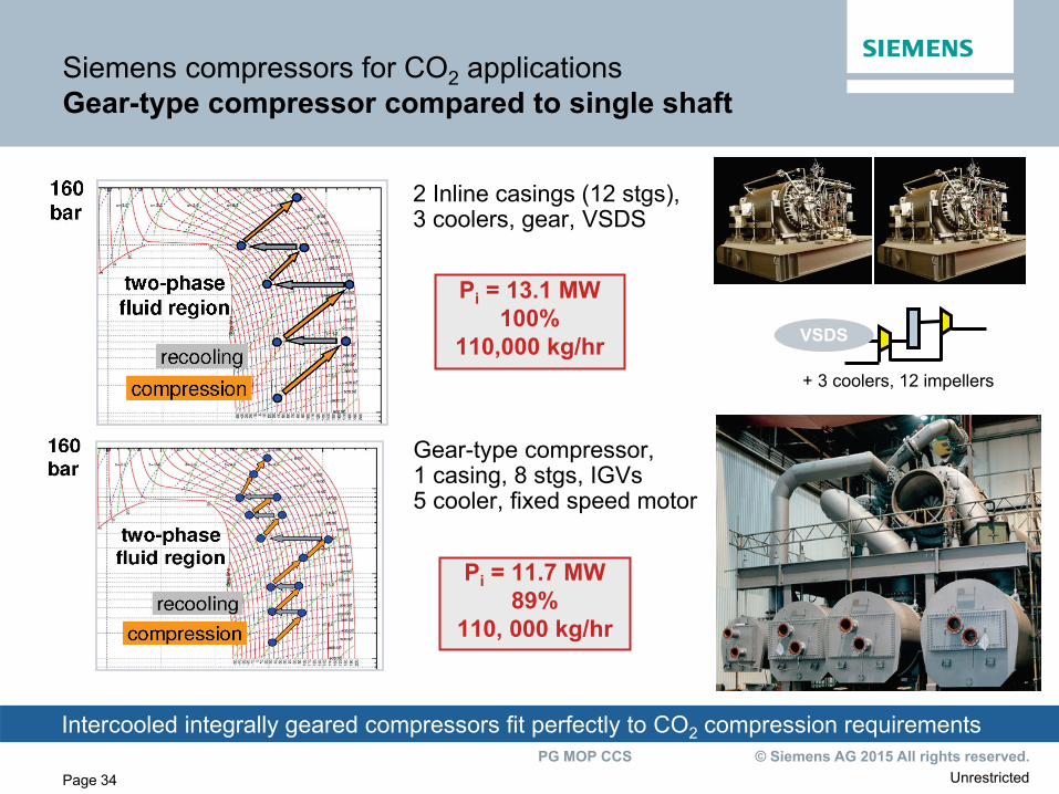
Siemens compressors for CO2 applications Gear-type compressor compared to single shaft
2 Inline casings (12 stgs), 3 coolers, gear, VSDS
Gear-type compressor, 1 casing, 8 stgs, IGVs 5 cooler, fixed speed motor
Pi = 13.1 MW 100%
110,000 kg/hr
Pi = 11.7 MW 89%
110, 000 kg/hr
Intercooled integrally geared compressors fit perfectly to CO2 compression requirements
+ 3 coolers, 12 impellers
VSDS
Page 34
Unrestricted © Siemens AG 2015 All rights reserved. PG MOP CCS
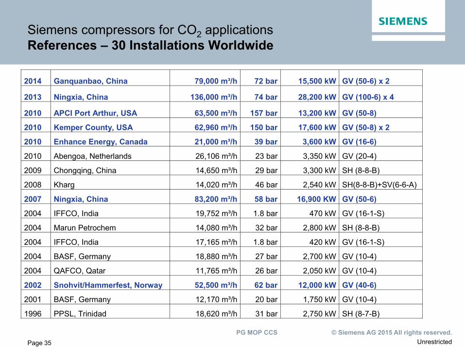
Siemens compressors for CO2 applications References – 30 Installations Worldwide
2014 Ganquanbao, China 79,000 m³/h 72 bar 15,500 kW GV (50-6) x 2
2013 Ningxia, China 136,000 m³/h 74 bar 28,200 kW GV (100-6) x 4
2010 APCI Port Arthur, USA 63,500 m³/h 157 bar 13,200 kW GV (50-8)
2010 Kemper County, USA 62,960 m³/h 150 bar 17,600 kW GV (50-8) x 2
2010 Enhance Energy, Canada 21,000 m³/h 39 bar 3,600 kW GV (16-6)
2010 Abengoa, Netherlands 26,106 m³/h 23 bar 3,350 kW GV (20-4)
2009 Chongqing, China 14,650 m³/h 29 bar 3,300 kW SH (8-8-B)
2008 Kharg 14,020 m³/h 46 bar 2,540 kW SH(8-8-B)+SV(6-6-A)
2007 Ningxia, China 83,200 m³/h 58 bar 16,900 KW GV (50-6)
2004 IFFCO, India 19,752 m³/h 1.8 bar 470 kW GV (16-1-S)
2004 Marun Petrochem 14,080 m³/h 32 bar 2,800 kW SH (8-8-B)
2004 IFFCO, India 17,165 m³/h 1.8 bar 420 kW GV (16-1-S)
2004 BASF, Germany 18,880 m³/h 27 bar 2,700 kW GV (10-4)
2004 QAFCO, Qatar 11,765 m³/h 26 bar 2,050 kW GV (10-4)
2002 Snohvit/Hammerfest, Norway 52,500 m³/h 62 bar 12,000 kW GV (40-6)
2001 BASF, Germany 12,170 m³/h 20 bar 1,750 kW GV (10-4)
1996 PPSL, Trinidad 18,620 m³/h 31 bar 2,750 kW SH (8-7-B)
Page 35
Unrestricted © Siemens AG 2015 All rights reserved. PG MOP CCS
Page 36
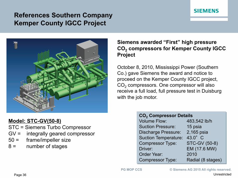
References Southern Company Kemper County IGCC Project
Siemens awarded “First” high pressure CO2 compressors for Kemper County IGCC Project October 8, 2010, Mississippi Power (Southern Co.) gave Siemens the award and notice to proceed on the Kemper County IGCC project, CO2 compressors. One compressor will also receive a full load, full pressure test in Duisburg with the job motor.
Model: STC-GV(50-8) STC = Siemens Turbo Compressor GV = integrally geared compressor 50 = frame/impeller size 8 = number of stages
CO2 Compressor Details Volume Flow: 483,542 lb/h Suction Pressure: 15 psia Discharge Pressure: 2,165 psia Suction Temperature: 43.0°C Compressor Type: STC-GV (50-8) Driver: EM (17.6 MW) Order Year: 2010 Compressor Type: Radial (8 stages)
Unrestricted © Siemens AG 2015 All rights reserved. PG MOP CCS
Page 37
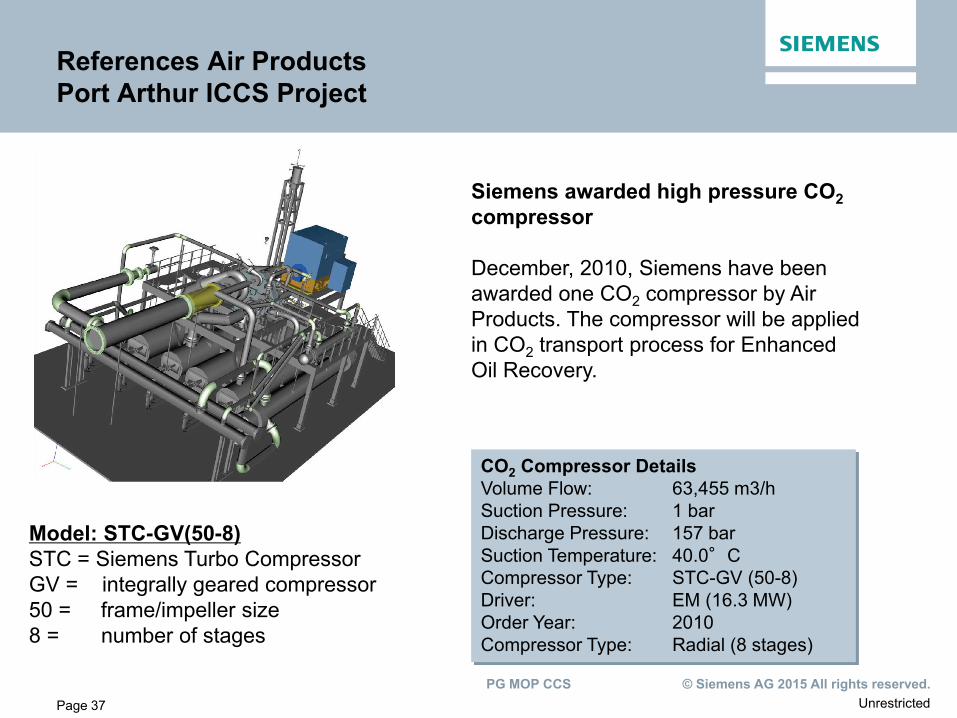
References Air Products Port Arthur ICCS Project
Siemens awarded high pressure CO2 compressor December, 2010, Siemens have been awarded one CO2 compressor by Air Products. The compressor will be applied in CO2 transport process for Enhanced Oil Recovery.
Model: STC-GV(50-8) STC = Siemens Turbo Compressor GV = integrally geared compressor 50 = frame/impeller size 8 = number of stages
CO2 Compressor Details Volume Flow: 63,455 m3/h Suction Pressure: 1 bar Discharge Pressure: 157 bar Suction Temperature: 40.0°C Compressor Type: STC-GV (50-8) Driver: EM (16.3 MW) Order Year: 2010 Compressor Type: Radial (8 stages)
Unrestricted © Siemens AG 2015 All rights reserved. PG MOP CCS
Page 38
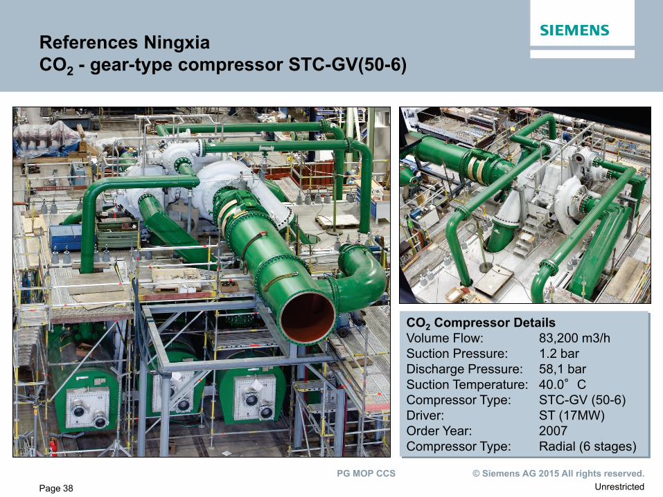
References Ningxia CO2 - gear-type compressor STC-GV(50-6)
CO2 Compressor Details Volume Flow: 83,200 m3/h Suction Pressure: 1.2 bar Discharge Pressure: 58,1 bar Suction Temperature: 40.0°C Compressor Type: STC-GV (50-6) Driver: ST (17MW) Order Year: 2007 Compressor Type: Radial (6 stages)
Unrestricted © Siemens AG 2015 All rights reserved. PG MOP CCS
Page 39
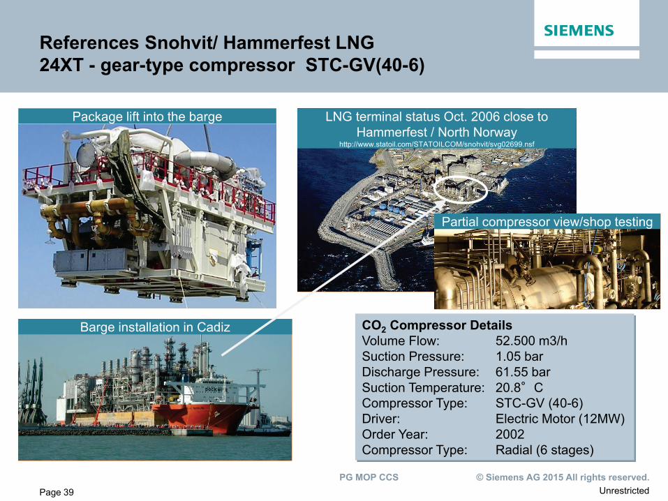
Package lift into the barge
Barge installation in Cadiz
LNG terminal status Oct. 2006 close to Hammerfest / North Norway
http://www.statoil.com/STATOILCOM/snohvit/svg02699.nsf
References Snohvit/ Hammerfest LNG 24XT - gear-type compressor STC-GV(40-6)
CO2 Compressor Details Volume Flow: 52.500 m3/h Suction Pressure: 1.05 bar Discharge Pressure: 61.55 bar Suction Temperature: 20.8°C Compressor Type: STC-GV (40-6) Driver: Electric Motor (12MW) Order Year: 2002 Compressor Type: Radial (6 stages)
Partial compressor view/shop testing
Unrestricted © Siemens AG 2015 All rights reserved. PG MOP CCS
Page 40
Content
Market Development
CCUS within Siemens
Technology Leadership with Siemens PostCapTM
Engineering Capabilities and References
Business Models and Implementation Strategy
Unrestricted © Siemens AG 2015 All rights reserved. PG MOP CCS
Page 41
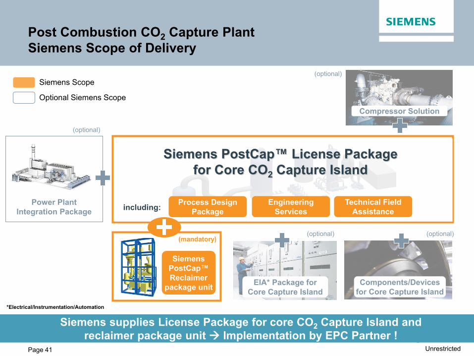
Post Combustion CO2 Capture Plant Siemens Scope of Delivery
Siemens supplies License Package for core CO2 Capture Island and reclaimer package unit Implementation by EPC Partner !
EIA* Package for Core Capture Island
Components/Devices for Core Capture Island
(optional)
Process Design Package including: Engineering
Services Technical Field
Assistance
Siemens PostCap™ License Package for Core CO2 Capture Island
(optional)
Power Plant Integration Package
(optional)
(optional)
Compressor Solution
Siemens Scope
Optional Siemens Scope
Siemens PostCap™ Reclaimer
package unit
(mandatory)
*Electrical/Instrumentation/Automation
Unrestricted © Siemens AG 2015 All rights reserved. PG MOP CCS
Page 42
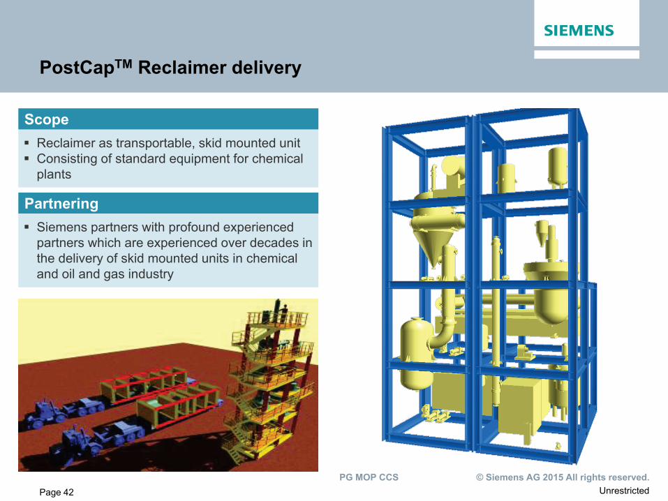
PostCapTM Reclaimer delivery
Reclaimer as transportable, skid mounted unit Consisting of standard equipment for chemical
plants
Siemens partners with profound experienced partners which are experienced over decades in the delivery of skid mounted units in chemical and oil and gas industry
Scope
Partnering
Unrestricted © Siemens AG 2015 All rights reserved. PG MOP CCS
Page 43
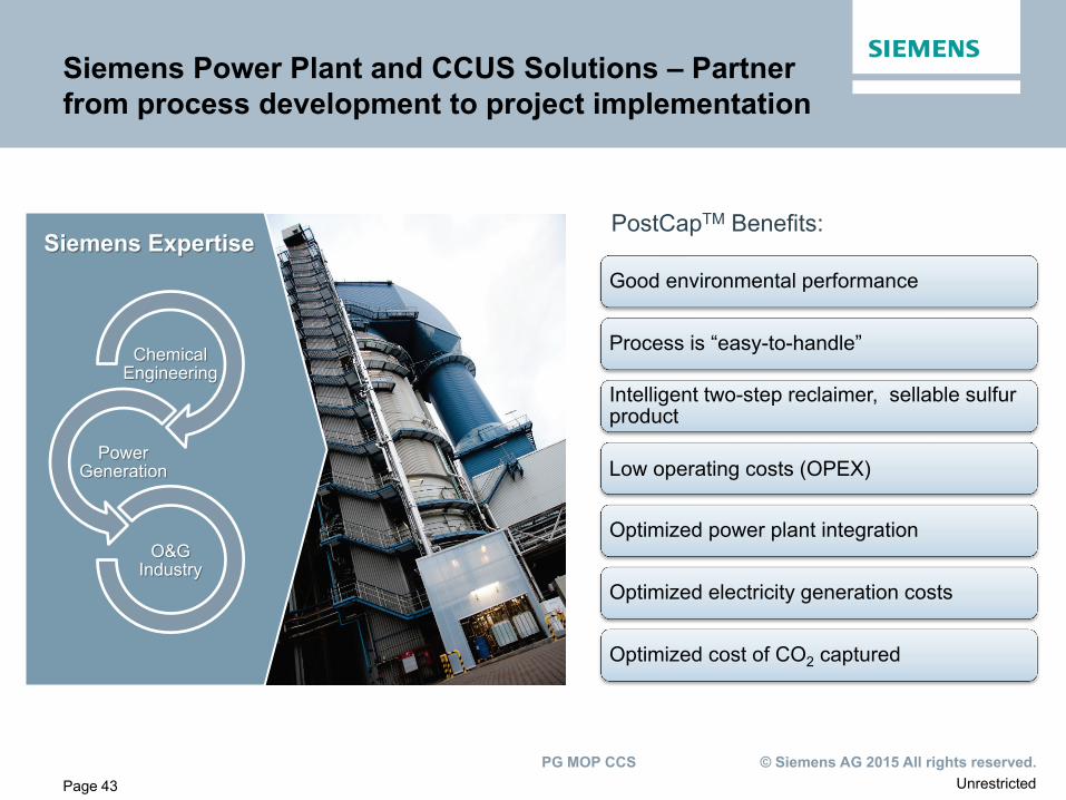
Siemens Power Plant and CCUS Solutions – Partner from process development to project implementation
Chemical Engineering
Power Generation
O&G Industry
Siemens Expertise Good environmental performance
Process is “easy-to-handle”
Intelligent two-step reclaimer, sellable sulfur product
Low operating costs (OPEX)
Optimized power plant integration
Optimized electricity generation costs
Optimized cost of CO2 captured
PostCapTM Benefits:
Unrestricted © Siemens AG 2015 All rights reserved. PG MOP CCS
Page 44
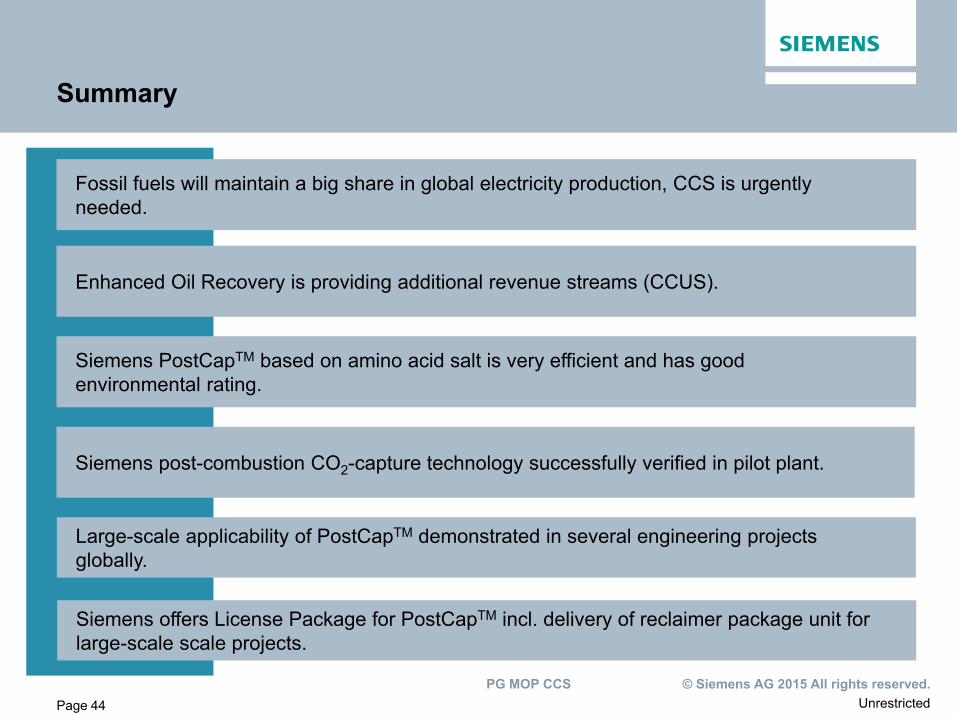
Fossil fuels will maintain a big share in global electricity production, CCS is urgently needed.
Siemens post-combustion CO2-capture technology successfully verified in pilot plant.
Enhanced Oil Recovery is providing additional revenue streams (CCUS).
Siemens PostCapTM based on amino acid salt is very efficient and has good environmental rating.
Summary
Large-scale applicability of PostCapTM demonstrated in several engineering projects globally.
Siemens offers License Package for PostCapTM incl. delivery of reclaimer package unit for large-scale scale projects.
Unrestricted © Siemens AG 2015 All rights reserved. PG MOP CCS
Find out more about PostCap™
www.siemens.com/energy/post-combustion-carbon-capture
Unrestricted © Siemens AG 2015 All rights reserved. PG MOP CCS
Page 46
Disclaimer
This document contains forward-looking statements and information – that is, statements related to future, not past, events. These statements may be identified either orally or in writing by words as “expects”, “anticipates”, “intends”, “plans”, “believes”, “seeks”, “estimates”, “will” or words of similar meaning. Such statements are based on our current expectations and certain assumptions, and are, therefore, subject to certain risks and uncertainties. A variety of factors, many of which are beyond Siemens’ control, affect its operations, performance, business strategy and results and could cause the actual results, performance or achievements of Siemens worldwide to be materially different from any future results, performance or achievements that may be expressed or implied by such forward-looking statements. For us, particular uncertainties arise, among others, from changes in general economic and business conditions, changes in currency exchange rates and interest rates, introduction of competing products or technologies by other companies, lack of acceptance of new products or services by customers targeted by Siemens worldwide, changes in business strategy and various other factors. More detailed information about certain of these factors is contained in Siemens’ filings with the SEC, which are available on the Siemens website, www.siemens.com and on the SEC’s website, www.sec.gov. Should one or more of these risks or uncertainties materialize, or should underlying assumptions prove incorrect, actual results may vary materially from those described in the relevant forward-looking statement as anticipated, believed, estimated, expected, intended, planned or projected. Siemens does not intend or assume any obligation to update or revise these forward-looking statements in light of developments which differ from those anticipated. Trademarks mentioned in this document are the property of Siemens AG, it's affiliates or their respective owners.