cnc manufacturing for complex products
TRANSCRIPT
International Conference 2ND International Conference on Innovations, Recent Trends and Challenges
in Mechatronics, Mechanical Engineering and New High-Tech Products Development
MECAHITECH‘10
Bucharest, 23-24 September 2010
284
Integrated Design Solutions- CNC Manufacturing for Complex
Products
St. Ganatios 1, O. Dontu 2, D. Besnea 2, R. Ciobanu 2, I. Avarvarei 2 1 University West Macedonia TEI Kozani - Greece
2 University “Politehnica” Buchaerest, Faculty of Mechanical Engineering and Mechatronics No.313 Splaiul Independentei, Sector 6, Bucharest, Romania
E-mail: [email protected], [email protected]
ABSTRACT
This paper presents a way to design parts with complex geometry and manufacturing techniques on machining centers with at least three numerically controlled axes. Using 3D Wireframe and Surface Design applications, we present steps to follow and conceiving mode, modeling and manufacturing of an injection mold for a plastic bottle emphasizing the constructive and design features.
INTRODUCTION
The need to machine complex surfaces led to the mergence of a new generation of products able to execute parts with 3D geometry and processing techniques on machines with at least three numerically controlled axes. This method was embraced by all manufacturers, in all the fields and at all the levels, starting from prototype to mass production and it’s well adapted to the specific needs of the manufacturing processes.
High technology is based on this type of processing, offering integrated solutions, from the tool path definition, verification and easy update, surface machining to providing solutions easy to learn and use. Surface processing completely covers the design-manufacturing cycle, providing functions for defining operations to be materialized by a machine, defining the processing strategy, processing row-roughing, finishing operations, unprocessed zone detection, or machining in vertical or horizontal planes, such as Zlevel machining, shaping, defining areas of processing, visualization of processing program, documentation generation, offering a freedom of choice for the working methods that suits best the needs of manufacturers.[1]
GENERAL PRESENTATION
NC Manufacturing allows defining and managing NC programs dedicated to parts that
are to be processed, designed in 3D wireframe or solid, using techniques from 2.5 up to 5 axes of processing. Being an unique solution, having a post processor engine that allows the product item to cover all the entire manufacturing process (APT source or CL file) to NC data., offering the following main functions :common platform for 2.5 – 5 axis;, flexible management of fabrication program, graphic interface based on dialog boxes; personalization features by f(x) formula, generation of data to a post processor and instant access to documentation in HTML format. High level of associability of manufacturing
International Conference 2ND International Conference on Innovations, Recent Trends and Challenges
in Mechatronics, Mechanical Engineering and New High-Tech Products Development
MECAHITECH‘10
Bucharest, 23-24 September 2010
285
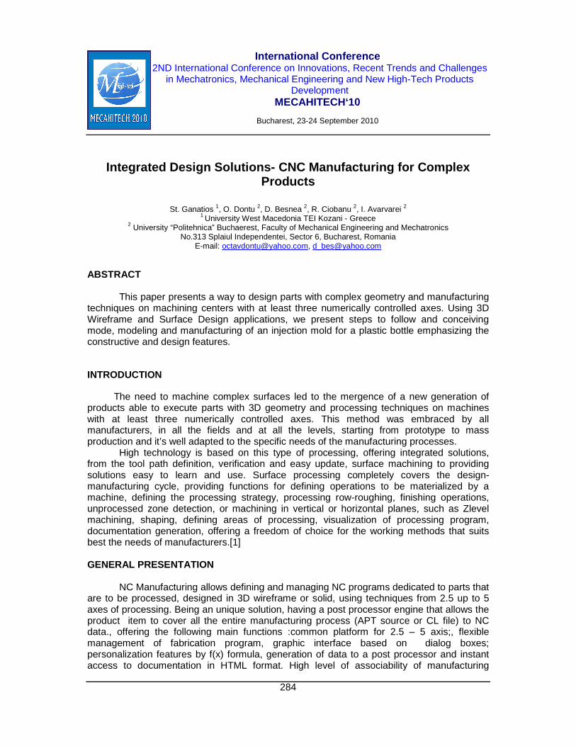
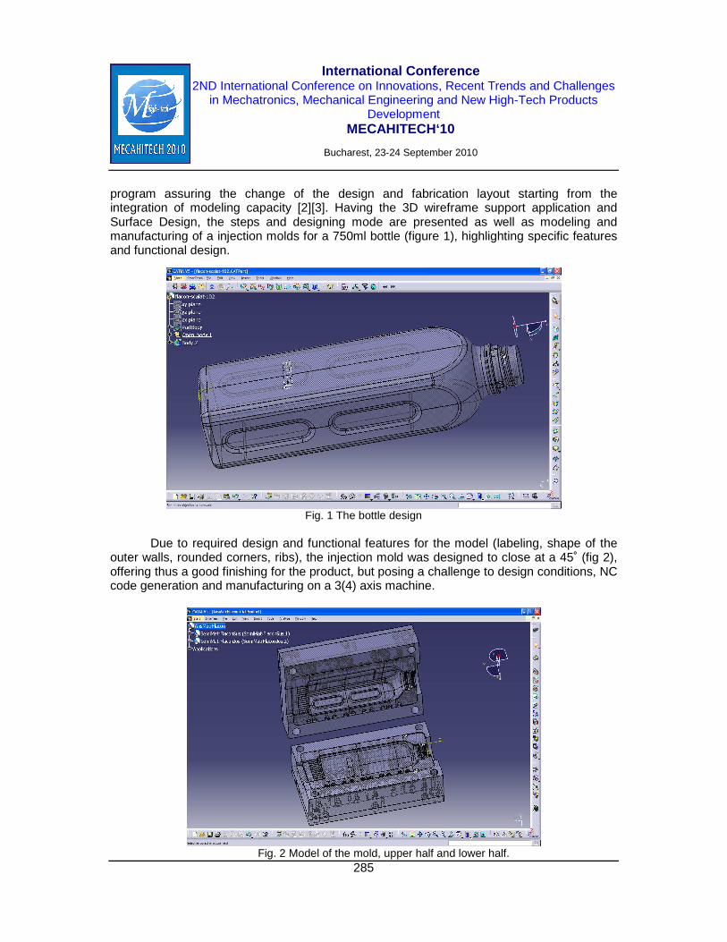
program assuring the change of the design and fabrication layout starting from the integration of modeling capacity [2][3]. Having the 3D wireframe support application and Surface Design, the steps and designing mode are presented as well as modeling and manufacturing of a injection molds for a 750ml bottle (figure 1), highlighting specific features and functional design.
Fig. 1 The bottle design
Due to required design and functional features for the model (labeling, shape of the
outer walls, rounded corners, ribs), the injection mold was designed to close at a 45˚ (fig 2), offering thus a good finishing for the product, but posing a challenge to design conditions, NC code generation and manufacturing on a 3(4) axis machine.
Fig. 2 Model of the mold, upper half and lower half.
International Conference 2ND International Conference on Innovations, Recent Trends and Challenges
in Mechatronics, Mechanical Engineering and New High-Tech Products Development
MECAHITECH‘10
Bucharest, 23-24 September 2010
286
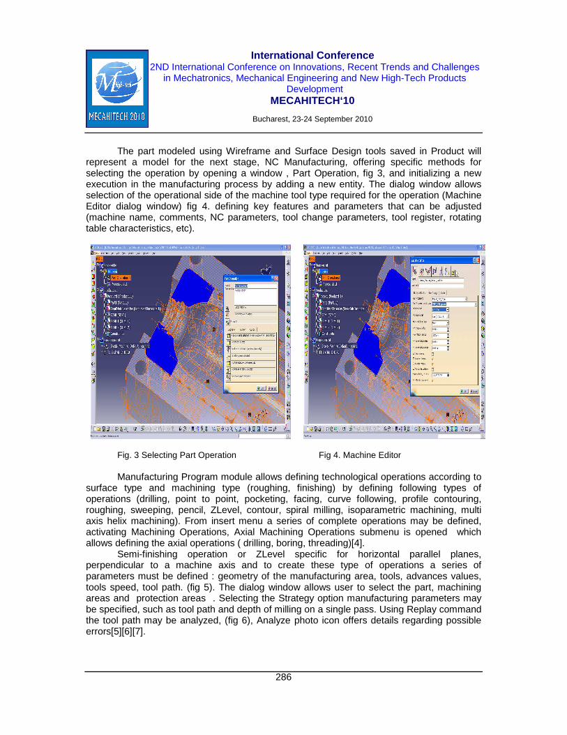
The part modeled using Wireframe and Surface Design tools saved in Product will represent a model for the next stage, NC Manufacturing, offering specific methods for selecting the operation by opening a window , Part Operation, fig 3, and initializing a new execution in the manufacturing process by adding a new entity. The dialog window allows selection of the operational side of the machine tool type required for the operation (Machine Editor dialog window) fig 4. defining key features and parameters that can be adjusted (machine name, comments, NC parameters, tool change parameters, tool register, rotating table characteristics, etc).
Fig. 3 Selecting Part Operation Fig 4. Machine Editor
Manufacturing Program module allows defining technological operations according to
surface type and machining type (roughing, finishing) by defining following types of operations (drilling, point to point, pocketing, facing, curve following, profile contouring, roughing, sweeping, pencil, ZLevel, contour, spiral milling, isoparametric machining, multi axis helix machining). From insert menu a series of complete operations may be defined, activating Machining Operations, Axial Machining Operations submenu is opened which allows defining the axial operations ( drilling, boring, threading)[4].
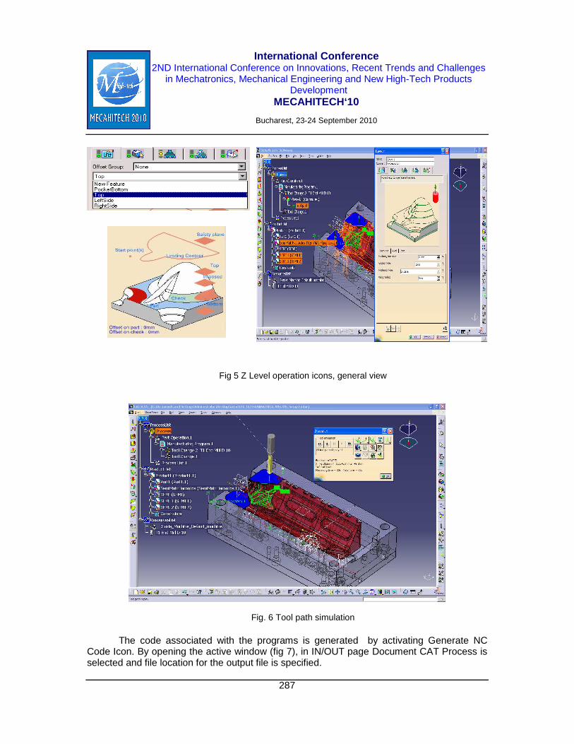
Semi-finishing operation or ZLevel specific for horizontal parallel planes, perpendicular to a machine axis and to create these type of operations a series of parameters must be defined : geometry of the manufacturing area, tools, advances values, tools speed, tool path. (fig 5). The dialog window allows user to select the part, machining areas and protection areas . Selecting the Strategy option manufacturing parameters may be specified, such as tool path and depth of milling on a single pass. Using Replay command the tool path may be analyzed, (fig 6), Analyze photo icon offers details regarding possible errors[5][6][7].
International Conference 2ND International Conference on Innovations, Recent Trends and Challenges
in Mechatronics, Mechanical Engineering and New High-Tech Products Development
MECAHITECH‘10
Bucharest, 23-24 September 2010
287
Fig 5 Z Level operation icons, general view
Fig. 6 Tool path simulation
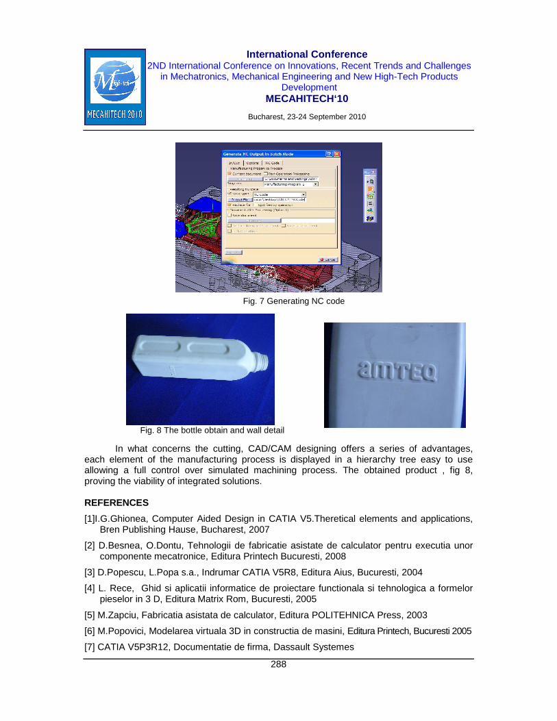
The code associated with the programs is generated by activating Generate NC Code Icon. By opening the active window (fig 7), in IN/OUT page Document CAT Process is selected and file location for the output file is specified.
International Conference 2ND International Conference on Innovations, Recent Trends and Challenges
in Mechatronics, Mechanical Engineering and New High-Tech Products Development
MECAHITECH‘10
Bucharest, 23-24 September 2010
288
Fig. 7 Generating NC code
Fig. 8 The bottle obtain and wall detail
In what concerns the cutting, CAD/CAM designing offers a series of advantages, each element of the manufacturing process is displayed in a hierarchy tree easy to use allowing a full control over simulated machining process. The obtained product , fig 8, proving the viability of integrated solutions.
REFERENCES
[1]I.G.Ghionea, Computer Aided Design in CATIA V5.Theretical elements and applications, Bren Publishing Hause, Bucharest, 2007
[2] D.Besnea, O.Dontu, Tehnologii de fabricatie asistate de calculator pentru executia unor componente mecatronice, Editura Printech Bucuresti, 2008
[3] D.Popescu, L.Popa s.a., Indrumar CATIA V5R8, Editura Aius, Bucuresti, 2004
[4] L. Rece, Ghid si aplicatii informatice de proiectare functionala si tehnologica a formelor pieselor in 3 D, Editura Matrix Rom, Bucuresti, 2005
[5] M.Zapciu, Fabricatia asistata de calculator, Editura POLITEHNICA Press, 2003
[6] M.Popovici, Modelarea virtuala 3D in constructia de masini, Editura Printech, Bucuresti 2005
[7] CATIA V5P3R12, Documentatie de firma, Dassault Systemes