closed-loop testing with the real-time digital power system simulator
TRANSCRIPT
E L S E V I E R Electric Power Systems Research 36 (1996) 181-190
|I,|OTHIO POW|H SWST[m$ H|$|nHOF!
Closed-loop testing with the real-time digital power system simulator 1
R.J. Marttila, E.P. Dick, D. Fischer, C.S. Mulkins Ontario Hydro Technologies, 800 Kipling Avenue, Toronto, Ont., Canada MSZ 5S4
Received 2 November 1995
Abstract
Most protection and control equipment is usually tested in the open-loop mode. However, closed-loop testing is often the only cost-effective approach. This paper highlights the areas where closed-loop testing of protective relays and control equipment is preferable. Test setups with a real-time digital simulator for closed-loop testing of protective relays, power system stabilizers, and controllers for controlled closing of individual poles of a shunt capacitor breaker are described.
Keywords: Digital simulation; Control system testing; Relay testing; Transient network analyzers
1. Introduction
Analog power system simulators, also known as tran- sient network analyzers (TNAs), have an inherent char- acteristic that allows convenient closed-loop testing of protection and control equipment. Closed-loop testing on a model power system mimics the in situ conditions and, therefore, provides readily decipherable informa- tion on the performance of the equipment. In closed- loop testing, the device under test provides an output, such as a tripping signal to open a breaker, that is used to connect or disconnect power equipment from the model system. In the case of digital simulators, Ontario Hydro Technologies (OHT) has developed the neces- sary capability and expertise to implement the means for utilization of real-time digital simulators to the fullest extent possible, including the capability for closed-loop testing.
This paper reviews the situations where closed-loop testing is preferred and which, in turn, dictate the use of a TNA or a real-time digital simulator that has the capability to interface with the equipment under test. The characteristics of the interface for control signals to the real-time digital simulator (RTDS) to enable closed-
Based on a paper presented at the First International Conference on Digital Power System Simulators (ICDS), College Station, TX, USA, 5-7 April 1995.
0378-7796/96/$15.00 © 1996 Elsevier Science S.A. All rights reserved SSDI 0378-7796(95)01030-0
loop testing are discussed. The paper describes the particulars of the closed-loop test setup for testing a feeder relay, a power system stabilizer, and a circuit breaker controller for controlling the closing instant of the individual poles of a shunt capacitor breaker. The test setup for the latter is described in more detail to indicate the extent of some closed-loop testing.
2. Situations where closed-loop testing is preferred
Most protection and control equipment can be tested in the open-loop mode such that the response of the equipment does not need to be fed back to the mod- elled system. This applies in cases where it can be assumed that the timing of the equipment's action, in response to power system events, does not influence the equipment's response to subsequent changes in the power system. For example, in the case of a transmis- sion iine relay in three-pole tripping applications with slow reclosure (typically 5 s), the relay's response will not be influenced on reclosure by the timing of the initial tripping action generated by the relay. This is because both the power system and the relay have settled to their new steady-state conditions by the time the reclosure takes place. Hence, since the initial condi- tion on reclosure of the line is not dependent on when the line was tripped, the test that results in the tripping
182 R.J. Marttila et a l . / Electric Power Systems Research 36 (1996) 181 190
action can be performed separately from the test that determines the relay's response to reclosure. Relays for protection of most other major power system appara- tus, i.e. generator protections, transformer protections, bus protections, and control equipment such as that for activating breakers, can be tested in this type of open- loop mode. However, there are exceptions where closed-loop testing is the preferred approach, as dis- cussed below.
In some situations, the closed-loop approach en- hances efficiency in the conduct of the tests. Also, in other situations, closed-loop testing is a requirement for properly determining the response of the equipment. Some of this includes: (a) transmission line relays in applications with fast reclosing of transmission lines (typically 0.5 s); (b) relays for out-of-step protection; (c) relays responding to frequency excursions; (d) transmis- sion line relays in single-pole autoreclose applications; (e) relays for distribution feeders with reclosure; (f) power system stabilizers for excitation system control of generators; (g) special controllers for opening or closing breakers.
In cases (a)-(e), the action of the relays creates dynamic conditions in the power system which are dependent on the timing of the relay actions. For example, in (a), a transmission line relay will, on reclos- ing, need to contend with a dynamic power system and possibly with dynamics within the relay, which are dependent on the timing of the initial response and action of the relay.
Control equipment is another class of equipment that may dictate closed-loop testing. Cases (f) and (g) are examples where this applies. In (f), the effectiveness of the stabilizer control action on power system stability can only be tested in the closed-loop mode. If labora- tory tests were not possible, the tests would have to be performed on the actual installation.
Case (g) refers to controlled opening or closing of breaker poles. Controlled opening of individual poles (ensuring opening at zero current) is beneficial in reac- tor switching [1]. Controlled closing of individual poles (ensuring closing at zero voltage) is beneficial in capac- itor switching [2]. As discussed in subsequent sections, there are many factors that influence the desired result so it becomes important to test the performance of the controller in the closed-loop mode.
The required closed-loop testing can be accomplished with a TNA or with a digital power system simulator with appropriate capabilities to interact with the equip- ment under test. An obvious requirement of the digital simulator is that it operates in real time so that the response of the protection or control equipment under test can be fed back into the simulation to effect the intended action immediately. The subsequent sections describe the RTDS system and its application in closed- loop testing.
3. Brief description of the RTDS
The RTDS system is state-of-the-art equipment for real-time digital simulation of power systems and their components. The digital approach to modelling pro- vides accuracy in component modelling and flexibility in component interconnection for representation of a power system.
The RTDS simulates the power system and its com- ponents in EMTD C software which is similar to the Electromagnetic Transients Program (EMTP) [3]. The modelled system is created using a graphics interface on a UNIX based workstation, with power system compo- nents selected using convenient icons. As with the EMTP, the RTDS system computes the time domain solution of bus voltages and branch currents, but in a computational period of only 50-100 las. The simula- tion proceeds indefinitely, with the output quantities fed to digital-to-analog (D/A) converters allowing signals to be applied to the device under test. The simulation can also be modified 'on the fly' with user defined control inputs, for example closing or opening switches to connect or disconnect components in the simulated power system.
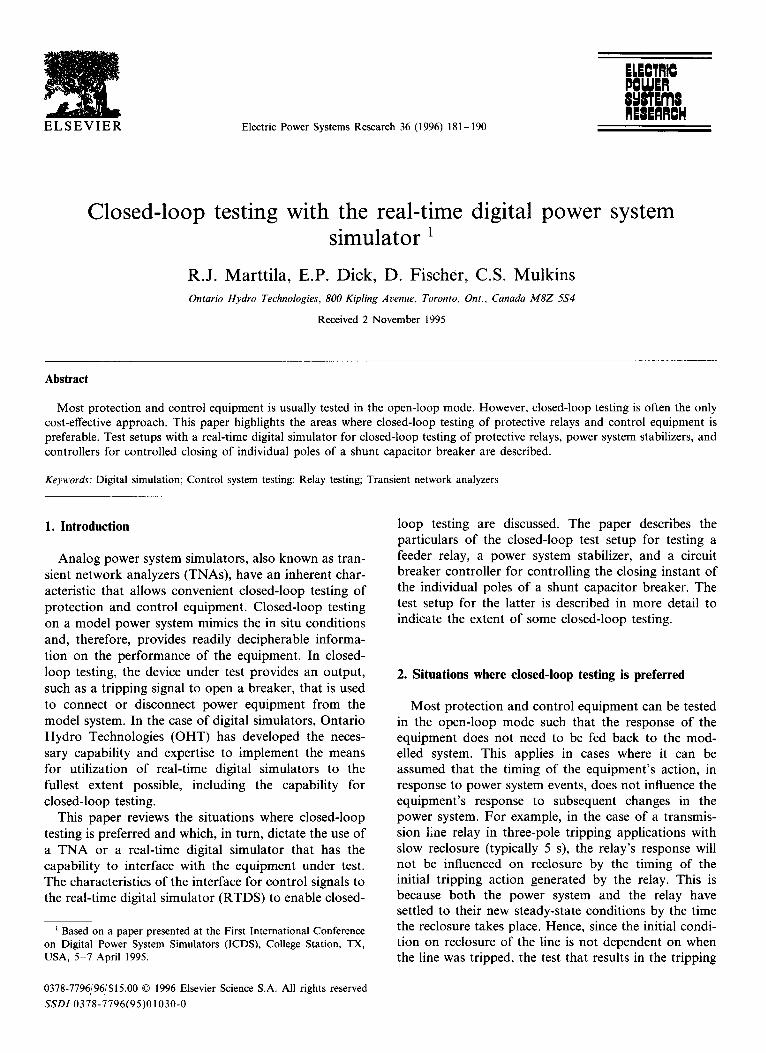
Fig. 1 shows an overview of the system hardware of the RTDS approach for testing power system equip- ment. A workstation provides the user interface to the RTDS. The voltage and current test signals generated in a user defined power system, and the status and analog control signals for controlling the simulation, are applied to an interface unit developed in-house. This equipment is used for the filtering and optical isolation of the signals. The filtered voltage and current signals are applied to the equipment under test via appropriate power amplifiers, the outputs of which are monitored by a 12-channel data acquisition system.
In addition to accepting analog and digital control signals as inputs to the simulation, the RTDS also provides status signals as outputs, e.g. position indica- tion of a breaker or a disconnect switch. The interfac- ing requirements are discussed below for different test applications.
4. Closed-loop testing of a feeder relay
New microprocessor based relays for protection of distribution feeders provide all the functions required in a single unit, including the reclosing feature. A feeder relay tha t was recently evaluated consisted of various instantaneous and timed overcurrent detectors for phase and ground overcurrent protection, phase phase distance elements for phase faults, a reclose feature, a fault location feature, an oscillographic function, a sequence-of-events function and a metering function. Although seemingly a straightforward application on
R.J. Marttila et al./Electric Power Systems Research 36 (1996) 181-190 183
I Real-Time I<~
I Digi~l Simulator ~
I ANALOG TEST
~ i ..~ SIGNALS
P STATUS CONTROL SIGNALS
ANALOG CONTROL SIGNALS
SUN WORKSTATION
FILTERS AND OPTICAL ISOLATION
2
W O
W
TO ANDFROM EQUIPMENT UNDER TEST
' I'RIGGER FOR EVENT START
~6 VOLTAGE
1 1 / 1 2 5 V rms POWER AMPLIFIERS [~ 40 A peak
I !~ 6 CURRENT
12 - CHANNEL
TO EQUIPMENT UNDER TEST
Fig. 1. Overview of the system hardware for the RTDS approach.
radial feeders, the relay was required to be tested in a closed-loop test setup because the reclose feature needed to be tested as an integral part of the protection.
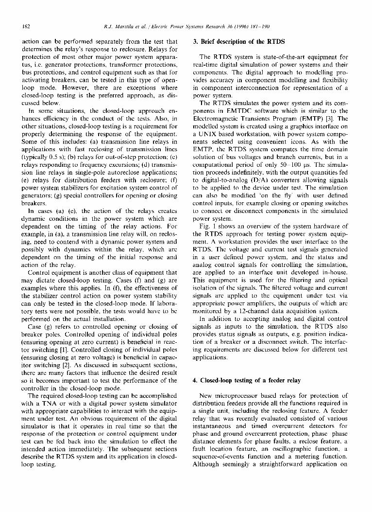
Fig. 2 shows the closed-loop test setup on the RTDS. The components enclosed by the dashed line pertain to the RTDS, which includes modelling of a simple radial system and the D/A and digital I/O for interfacing external signals. The rest of the test system components shown in Fig. 2 have been fabricated in-house, which include the fault selection unit, the sequence controller (SC) and the interface unit consisting of optically iso- lated buffer amplifiers to interface the D/A and the I/O to external devices, as mentioned previously. As shown in Fig. 2, three-phase voltage and current signals from the modelled system are brought to the power amplifi- ers via the D/A converters of the RTDS, through the buffer amplifiers and filters of the interface unit. The amplified signals from the power amplifiers are then connected to the relay inputs. The feeder relay controls the feeder breaker via its trip and close contacts which connect 125 V DC (or 250 V) to the interface unit. The DC control voltage is converted by the optically iso- lated interface to a level acceptable to the digital I/O inputs of the RTDS. The signal indicating the status of the breaker (open or closed) is brought to the relay via digital I/O and the interface unit, which in turn drives an auxiliary relay with a dry contact. When the breaker contact is closed, the status signal from the breaker closes the auxiliary relay contact, applying 125 V DC to the 52 A input of the relay under te~t, as required.
The feeder modelled on the RTDS consists of several
sections of line of equal length to enable testing of the performance of the protection and the fault location feature, with the fault and the shunt load at different locations on the feeder. To change the location of the fault or the load requires the modelled system to be recompiled and reloaded to the RTDS hardware. This task is not considered highly disruptive in the execution of a test program. However, to avoid recompilation and reloading of a revised case when changing the fault type or point-on-wave of initiation of the fault, the fault is applied through a breaker that is controlled externally. The fault selection unit and the sequence controller, which controls the fault instant, is interfaced through the interface unit and the digital I/O of the RTDS. The sequence controller, which is referenced to the modelled system voltage, consists of a number of a dry contacts, the closing (or opening) of which can be delayed with respect to the zero crossing of the refer- ence voltage. The delay time can be selected to a resolution of 1/100th of a cycle.
All the usual types of faults can be selected with the fault selection unit, i.e. three-phase, phase-phase, phase--ground, and phase-phase-ground . The ground faults can be applied with or without fault resistance, but the value of the resistance needs to be chosen at compilation time. The process of the fault selection and the sequence control are interconnected (not shown) such that evolving faults can be implemented. Various combinations of faults, and the point-on-wave at which the fault occurs, can be conveniently implemented by making the appropriate fault selection and by selecting
184 R.J. Marttila et al./Electric Power Systems Research 36 (1996) 181-190
. . . . . . . . . . . . . . . . . . . . . . . . . . . . . . . . . . . . . . . . . . . . . . . . . . . . . . . . . . . . . fif6~"
DIA AND I V~-- DIGITAL I/0 [g/Ay_.
FEEDER RELAY UNDER TEST
----1 1
, ,oo 1 U 1 I
CURIIIT ~TT~RIP C!SE 5~2A REFERENCE VOLTAGE FOR CONTROL
x '
L~FAULT SELuENCITTION
TRIGGER RECORDING
L SEQUENCE I CONTROLLER
(sc)
,, - Control Fault
Initiation
Fig. 2. Setup for closed-loop testing of a feeder relay on the RTDS.
the appropriate delay times on the sequence controller. This is achieved without recompiling and reloading a revised case.
The recompiling and reloading required when the position of the shunt load and/or the fault is changed could also be avoided by implementing a feeder model that contains the model of a shunt load and the faults at each node of the faulted feeder. In this case, each load and fault need to be connected to the feeder via switches which are externally controlled to enable their connection or disconnection. In this way the location of the load and the fault could be selected 'on the fly' while the case is running, in the same way as the selection of the fault type discussed above. However, this requires a complement of switches that is larger than the capability of the present RTDS system and, therefore, this could not be implemented with the present design of the RTDS.
5. Closed-loop testing of a power system stabilizer
A power system stabilizer modulates the excitation of a generating unit in response to events in the power system to which it is connected. The modulation is effected in such a manner as to reduce speed excursions from synchronous and, thereby, maintain stability of the unit. The presence of a power system stabilizer enables the generating unit to survive (maintain syn- chronism or remain stable) the occurrence of power system events (e.g. transmission system faults) at higher power output levels. Hence, power system stabilizers are installed to maximize the power output capability of the generating units.
A new digital power system stabilizer (PSS) was recently developed at OHT and the prototype was tested on the RTDS. The tests were designed to un- cover any operational glitches and to fine tune the digital algorithms of the stabilizer function, the user interface, and the built-in test facility. Once the proto- type was tested and modified as required to perform as per the design specifications, further tests were per- formed to fine tune the calculated settings for a particu- lar installation. Without the RTDS facility to serve as a test installation, the prototype testing would have re- quired costly field testing on an actual generating unit. Also, the opportunity to perform initial fine tuning of the stabilizer settings for a particular installation saved a lot of time during commissioning of the stabilizer.
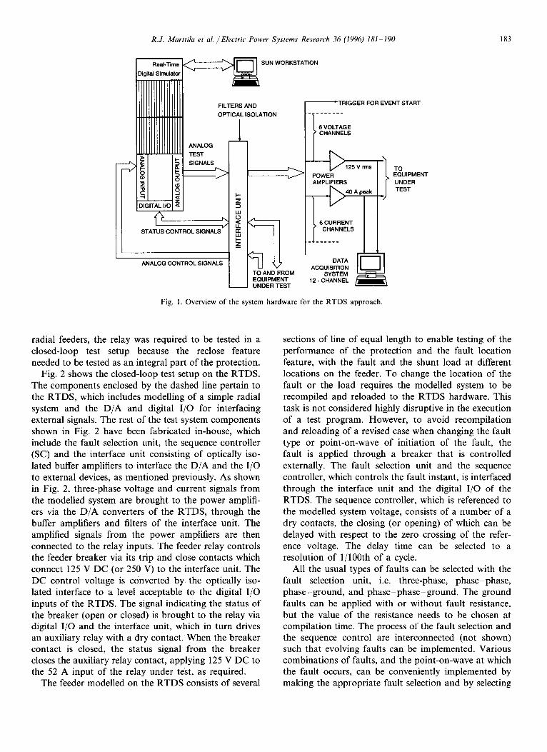
Fig. 3 shows a block diagram of the setup for testing the stabilizer. As in Fig. 2, the RTDS components are enclosed by the dashed line and the external signals are connected to the RTDS by the interface unit. Closed- loop tests are performed, with the stabilizing voltage signal (VSTAB) acting on the excitation of the unit. VSTAB, which is derived by the stabilizer from the generator terminal voltages and stator currents, is inter- faced to the exciter model via an A/D converter on the RTDS. This converter converts the external analog signal to the digital signal required by the RTDS model of the exciter.
As in the case of the setup for testing the feeder relay, the sequence controller and the fault selection unit are interfaced to the model power system through the interface unit and the digital I/O. In this case, however, the sequence controller controls the trip and close operations of the line breaker in addition to controlling the fault initiation.
R.J. Marttila et al . / Electric Power Systems Research 36 (1996) 181-190 185
I il ,NF,N,TE
FAULT
_ I - - ] D/A AND DIGITAL I/O I D/A %/ r
: AN_O_ ~P_ _ _ - ~ INTERFACE I
UNIT I ~
POWER \ / AMP V
POWER I SYSTEM I
STABILIZER I VOLTAGE UNDER T E S T ~
7 ND L
I ER ; VSTAB
CURRENT
I/0 i
REFERENCE VOLTAGE FOR CONTROL
T"]ggg NG
SEQUENCE I CONTROLLER: I
a . Control Breaker - Control Fault
Initiation
Fig. 3. Test setup for closed-loop testing of a power system stabilizer on the RTDS.
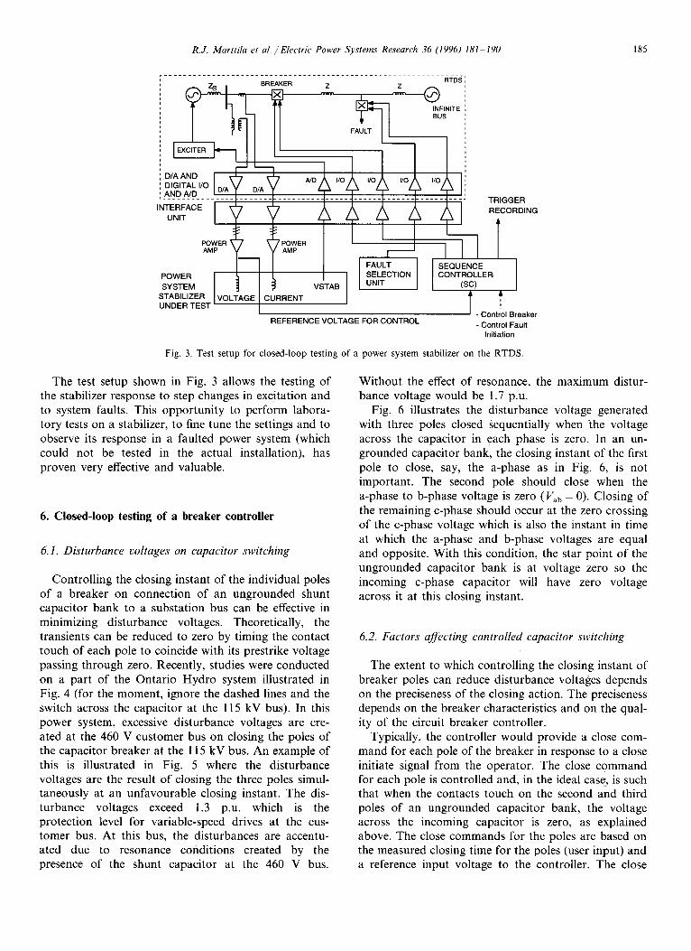
The test setup shown in Fig. 3 allows the testing of the stabilizer response to step changes in excitation and to system faults. This opportunity to perform labora- tory tests on a stabilizer, to fine tune the settings and to observe its response in a faulted power system (which could not be tested in the actual installation), has proven very effective and valuable.
6. Closed-loop testing of a breaker controller
6.1. Disturbance voltages on capacitor switching
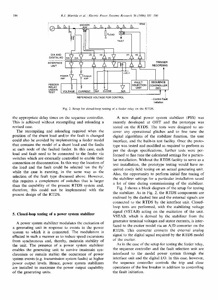
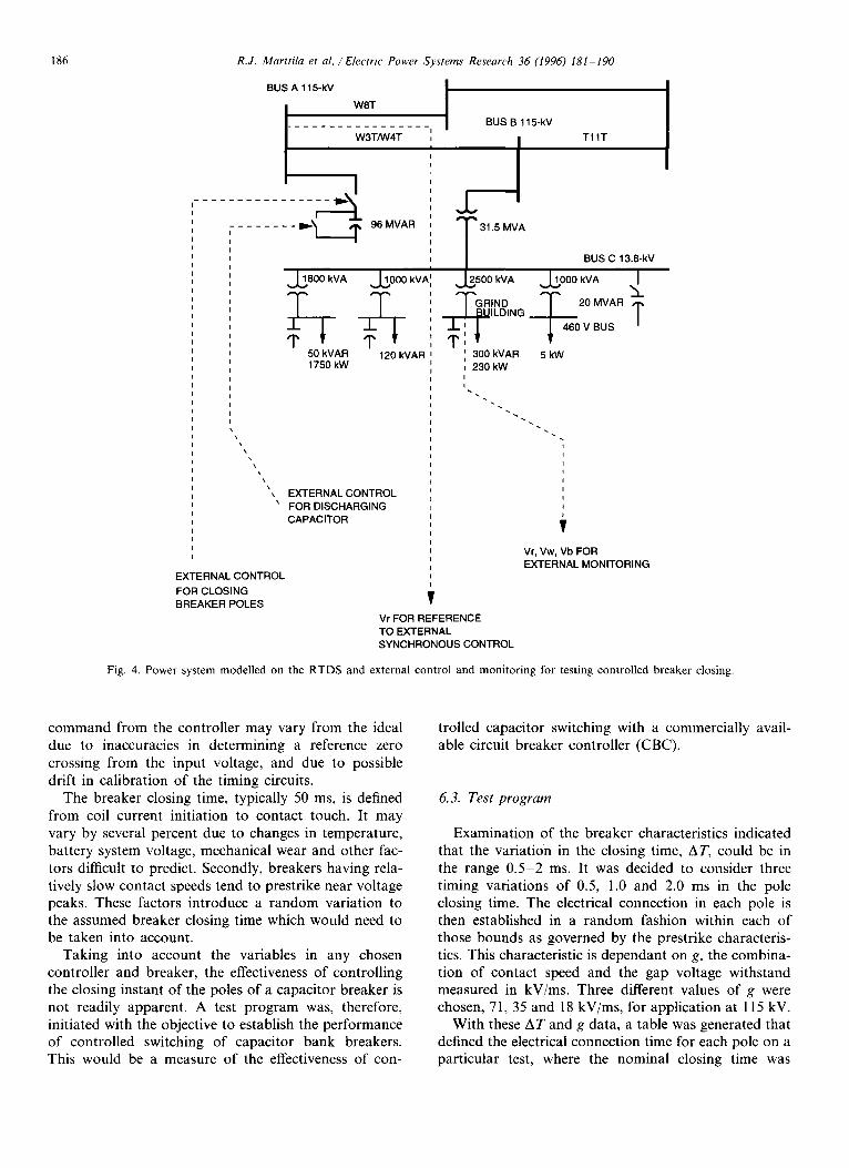
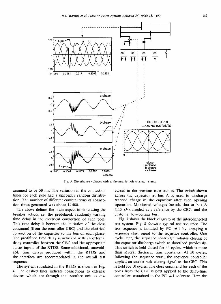
Controlling the closing instant of the individual poles of a breaker on connection of an ungrounded shunt capacitor bank to a substation bus can be effective in minimizing disturbance voltages. Theoretically, the transients can be reduced to zero by timing the contact touch of each pole to coincide with its prestrike voltage passing through zero. Recently, studies were conducted on a part of the Ontario Hydro system illustrated in Fig. 4 (for the moment, ignore the dashed lines and the switch across the capacitor at the 115 kV bus). In this power system, excessive disturbance voltages are cre- ated at the 460 V customer bus on closing the poles of the capacitor breaker at the 115 kV bus. An example of this is illustrated in Fig. 5 where the disturbance voltages are the result of closing the three poles simul- taneously at an unfavourable closing instant. The dis- turbance voltages exceed 1.3 p.u. which is the protection level for variable-speed drives at the cus- tomer bus. At this bus, the disturbances are accentu- ated due to resonance conditions created by the presence of the shunt capacitor at the 460 V bus.
Without the effect of resonance, the maximum distur- bance voltage would be 1.7 p.u.
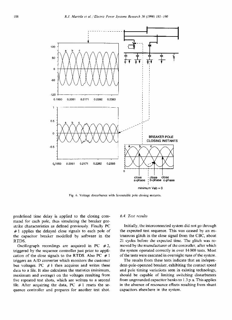
Fig. 6 illustrates the disturbance voltage generated with three poles closed sequentially when the voltage across the capacitor in each phase is zero. In an un- grounded capacitor bank, the closing instant of the first pole to close, say, the a-phase as in Fig. 6, is not important. The second pole should close when the a-phase to b-phase voltage is zero (Vab = 0 ) . Closing of the remaining c-phase should occur at the zero crossing of the c-phase voltage which is also the instant in time at which the a-phase and b-phase voltages are equal and opposite. With this condition, the star point of the ungrounded capacitor bank is at voltage zero so the incoming c-phase capacitor will have zero voltage across it at this closing instant.
6.2. Factors affecting controlled capacitor switching
The extent to which controlling the closing instant of breaker poles can reduce disturbance voltages depends on the preciseness of the closing action. The preciseness depends on the breaker characteristics and on the qual- ity of the circuit breaker controller.
Typically, the controller would provide a close com- mand for each pole of the breaker in response to a close initiate signal from the operator. The close command for each pole is controlled and, in the ideal case, is such that when the contacts touch on the second and third poles of an ungrounded capacitor bank, the voltage across the incoming capacitor is zero, as explained above. The close commands for the poles are based on the measured closing time for the poles (user input) and a reference input voltage to the controller. The close
186 R.J. Marttila et al./Electric Power Systems Research 36 (1996) 181 190
BUS A 115-RV I
! W8T . . . . . . . . . . . . . . . . BUS B 115-kV
W3T/W4T T 11T
96 MVAR T 3 1 1 . 5 MVA BUS C 13.8-kV
j:8ookv, J ooo.vA W
"1" I" 50 kVAR 120 kVAR 1750 kW
RIND ILDING
300 kVAR I , 230 kW I I
EXTERNALCONTROL FOR DISCHARGING CAPACITOR
EXTERNALCONTROL FOR CLOSING BREAKER POLES
T 20 MVAR ~L.
I- oov os T 5 kW
T Vr, Vw, Vb FOR EXTERNAL MONITORING
T VrFOR REFERENCE TO EXTERNAL SYNCHRONOUS CONTROL
Fig. 4. Power system modelled on the RTDS and external control and monitoring for testing controlled breaker closing.
command from the controller may vary from the ideal due to inaccuracies in determining a reference zero crossing from the input voltage, and due to possible drift in calibration of the timing circuits.
The breaker closing time, typically 50 ms, is defined from coil current initiation to contact touch. It may vary by several percent due to changes in temperature, battery system voltage, mechanical wear and other fac- tors difficult to predict. Secondly, breakers having rela- tively slow contact speeds tend to prestrike near voltage peaks. These factors introduce a random variation to the assumed breaker closing time which would need to be taken into account.
Taking into account the variables in any chosen controller and breaker, the effectiveness of controlling the closing instant of the poles of a capacitor breaker is not readily apparent. A test program was, therefore, initiated with the objective to establish the performance of controlled switching of capacitor bank breakers. This would be a measure of the effectiveness of con-
trolled capacitor switching with a commercially avail- able circuit breaker controller (CBC).
6.3. Test program
Examination of the breaker characteristics indicated that the variation in the closing time, AT, could be in the range 0.5-2 ms. It was decided to consider three timing variations of 0.5, 1.0 and 2.0 ms in the pole closing time. The electrical connection in each pole is then established in a random fashion within each of those bounds as governed by the prestrike characteris- tics. This characteristic is dependant on g, the combina- tion of contact speed and the gap voltage withstand measured in kV/ms. Three different values of g were chosen, 71, 35 and 18 kV/ms, for application at 115 kV.
With these AT and g data, a table was generated that defined the electrical connection time for each pole on a particular test, where the nominal closing time was
R.J. Marttila et a l . / Electric Power Systems Research 36 (1996) 181-190
12o:
-120
II . . . . . . . . . . . . . . . . . . i i
0.1950 0.2061 0.2171 0.2282 0.2393
~L d,
! I I
a-phase I
0.5 . - - " J
/ t t i I I I I 0.5 A b-phase /
/ I / t o
-0.5 . 1 I
t
] c-phase l , '
0. I ~ l 0
close -0.5 ~. 2.4 pu . ~ ] a-phase D-pnase
0.1950 0.2061 0.2171 0.2282 0.2393 c-pnase seconds
Fig. 5. Disturbance voltages with unfavourable pole closing instants.
BREAKER POLE CLOSINGINSTANTS
187
assumed to be 50 ms. The variation in the connection times for each pole had a uniformly random distribu- tion. The number of different combinations of connec- tion times generated was about 14400.
The above defines the main aspect in simulating the breaker action, i.e. the predefined, randomly varying time delay in the electrical connection of each pole. This time delay is between the initiation of the close command (from the controller CBC) and the electrical connection of the capacitor to the bus on each phase. The predifined time delay is achieved with an external delay controller between the CBC and the appropriate status inputs of the RTDS. Some additional, unavoid- able time delays produced within the RTDS and the interface are accommodated in the overall test sequence.
The system simulated in the RTDS is shown in Fig. 4. The dashed lines indicate connections to external devices which are through the interface unit as dis-
cussed in the previous case studies. The switch shown across the capacitor at bus A is used to discharge trapped charge in the capacitor after each opening operation. Monitored voltages include that at bus A (115 kV), needed as a reference by the CBC, and the customer low-voltage bus.
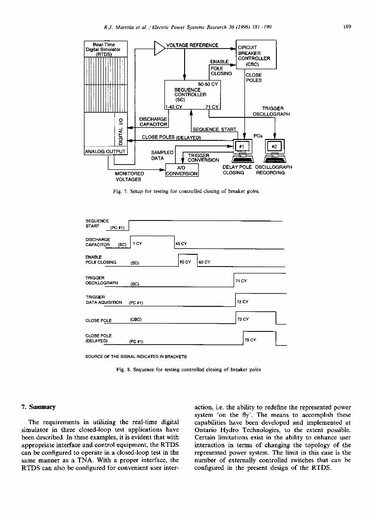
Fig. 7 shows the block diagram of the interconnected test system. Fig. 8 shows a typical test sequence. The test sequence is initiated by PC # 1 by applying a sequence start signal to the sequence controller. One cycle later, the sequence controller initiates closing of the capacitor discharge switch as described previously. This switch is held closed for 44 cycles, which is more than several discharge time constants. At 50 cycles, following the sequence start, the sequence controller applied an enable pole closing signal to the CBC. This is held for 10 cycles. The close command for each of the poles from the CBC is next applied to the delay-time controller, contained in the PC # 1 software. Here the
188 R.J. Marttila et al./Electric Power Systems Research 36 (1996) 181-190
120
° °
o
-60 ~
-120 0.1950 0.2061 0.2171 0.2282 0.2393
1
0.5 ~ ~ ~ .
-0.5
0.1950 0.2061 0.2171 0.2282 0.2393
I I
J- ,I
BREAKER POLE CLOSING INSTANTS
0
close close close a-phase b-phase c-phase
minimum Vab = 0
Fig. 6. Voltage disturbance with favourable pole closing instants.
predefined time delay is applied to the closing com- mand for each pole, thus simulating the breaker pre- strike characteristics as defined previously. Finally PC # 1 applies the delayed close signals to each pole of the capacitor breaker modelled by software in the RTDS.
Oscillograph recordings are acquired in PC # 2, triggered by the sequence controller just prior to appli- cation of the close signals to the RTDS. Also PC # 1 triggers an A/D converter which monitors the customer bus voltages. PC # 1 then acquires and writes these data to a file. It also calculates the statistics (minimum, maximum and average) on the voltages resulting from five repeated test shots, which are written to a second file. After acquiring the data, PC # 1 resets the se- quence controller and prepares for another test shot.
6.4. Test results
Initially, the interconnected system did not go through the expected test sequence. This was caused by an ex- traneous glitch in the close signal from the CBC, about 21 cycles before the expected time. The glitch was re- moved by the manufacturer of the controller, after which the system operated correctly in over 14 000 tests. Most of the tests were executed in overmght runs of the system.
The results from these tests indicate that an indepen- dent-pole-operated breaker, exhibiting the contact speed and pole timing variations seen in existing technology, should be capable of limiting switching disturbances from ungrounded capacitor banks to 1.3 p.u. This applies in the absence of resonance effects resulting from shunt capacitors elsewhere in the system.
R.J. Marttila et al./Electric Power Systems Research 36 (1996) 181-190 189
Real-Time Digital Simulator
(RTD:
IIIII
o
4
[ ~ VOLTAGE REFERENCE -v[ CIRCUIT -I BREAKER
CONTROLLER ENABLE (CBC)
CLOSE POLES
ANALOG ~UTUTI I SAMPLEDDATA I ~' CoN~TRIG / ' '
ND MONITORED ~CONVERSION I VOLTAGES
50-60 CY [ SEQUENCE [ CONTROLLER ] (sc)
1-45 CY 71 CY
I DISCHARGE CAPACITOR
SEQUENCE START CLOSE POLES (DELAYED)
TRIGGER CONVERSION
TRIGGER OSCILLOGRAPH
~ PCs [
DELAY POLE OSCILLOGRAPH CLOSING RECORDING
Fig. 7. Setup for testing for controlled closing of breaker poles.
SEQUENCE [ START (PC #1)
I DISCHARGE I 45 CY CAPACITOR (SC) 1 CY
ENABLE POLE CLOSING (SC) 60 CY
TRIGGER OSCILLOGRAPH (SC)
TRIGGER DATA AQUlSITION (PC #1 )
CLOSE POLE (CBC)
CLOSE POLE (DELAYED) (PC #1 )
71 CY
72 CY
72 CY
J75 CY
SOURCE OF THE SIGNAL INDICATED IN BRACKETS
Fig. 8. Sequence for testing controlled closing of breaker poles
7. Summary
The requirements in utilizing the real-time digital simulator in three closed-loop test applications have been described. In these examples, it is evident that with appropriate interface and control equipment, the RTDS can be configured to operate in a closed-loop test in the same manner as a TNA. With a proper interface, the RTDS can also be configured for convenient user inter-
action, i.e. the ability to redefine the represented power system 'on the fly'. The means to accomplish these capabilities have been developed and implemented at Ontario Hydro Technologies, to the extent possible. Certain limitations exist in the ability to enhance user interaction in terms of changing the topology of the represented power system. The limit in this case is the number of externally controlled switches that can be configured in the present design of the RTDS.

190 R.J. Marttila et al./Electric Power Systems Research 36 (1996) 181 190
References
[1] R.J. Rajotte et al., Field tests of a circuit breaker synchronous control, IEEE Trans. Power Delivery, 10 (3) (1995) 1301-1309.
[2] R.W. Alexander, Synchronous closing control for shunt capac-
itors, IEEE Trans. Power Appar. Syst., PAS-104 (1985) 2619- 2626.
[3] P.G. McLaren, R. Kuffel, R. Weirckx, J. Giesbrecht and L. Arendt, A real time digital simulator for testing relays, Trans. Power Delivery, 7 (1) (1992) 207 213.