class 900 flanges - thermometrics...
TRANSCRIPT

Dimensions for Class 900 Flanges
Nom. Pipe Size (inches) O Q* R X
No. and** Dia of Bolt
Holes
Bolt Circle Dia.
YY* H J Y* B r YV BB Z C T
1/2 4.75 0.88 1.38 1.50 4-0.88 3.25 2.38 0.84 1.25 0.88 0.12 1.25 0.90 0.93 0.88 3/4 5.12 1.00 1.69 1.75 4-0.88 3.50 2.75 1.05 1.38 1.09 0.12 1.38 1.11 1.14 1.00 1 5.88 1.12 2.00 2.06 4-1.00 4.00 2.88 1.32 1.62 1.36 0.12 1.62 1.38 1.41 1.12 11/4 6.25 1.12 2.50 2.50 4-1.00 4.38 2.88 1.66 1.62 1.70 0.19 1.62 1.72 1.75 1.19 11/2 7.00 1.25 2.88 2.75 4-1.12 4.88 3.25 1.90 1.75 1.95 0.25 1.75 1.97 1.99 1.25 2 8.50 1.50 3.62 4.12 8-1.00 6.50 4.00 2.38 2.25 2.44 0.31 2.25 2.46 2.50 1.50 21/2 9.62 1.62 4.12 4.88 8-1.12 7.50 4.12 2.88 2.50 2.94 0.31 2.50 2.97 3.00 1.88 3 9.50 1.50 5.00 5.00 8-1.00 7.50 4.00 3.50 2.12 3.57 0.38 2.12 3.60 3.63 1.62 4 11.50 1.75 6.19 6.25 8-1.25 9.25 4.50 4.50 2.75 4.57 0.44 2.75 4.60 4.63 1.88 5 13.75 2.00 7.31 7.50 8-1.38 11.00 5.00 5.56 3.12 5.66 0.44 3.12 5.69 5.69 2.12 6 15.00 2.19 8.50 9.25 12-1.25 12.50 5.50 6.63 3.38 6.72 0.50 3.38 6.75 6.75 2.25 8 18.5 2.50 10.62 11.75 12-1.50 15.5 6.38 8.63 4.00 8.72 0.50 4.5 8.75 8.75 2.50 10 21.50 2.75 12.75 14.50 16-1.50 18.50 7.25 10.75 4.25 10.88 0.50 5.00 10.92 10.88 2.81 12 24.00 3.12 15.00 16.50 20-1.50 21.00 7.88 12.75 4.62 12.88 0.50 5.62 12.92 12.94 3.00 14 25.25 3.38 16.25 17.75 20-1.62 22.00 8.38 14.00 5.12 14.14 0.50 6.12 14.18 14.19 3.25 16 27.75 3.50 18.50 20.00 20-1.75 24.25 8.5 16.00 5.25 16.16 0.50 6.50 16.19 16.19 3.38 18 31.00 4.00 21.00 22.25 20-2.00 27.00 9.00 18.00 6.00 18.18 0.50 7.50 18.20 18.19 3.50 20 33.75 4.25 23.00 24.50 20-2.12 29.50 9.75 20.00 6.25 20.20 0.50 8.25 20.25 20.19 3.62 24 41.00 5.50 27.25 29.50 20-2.62 35.50 11.50 24.00
To Be
S p e c i f i e d
by
P u r c a s e r
8.00 24.25 0.50 10.50 24.25 24.19 4.00
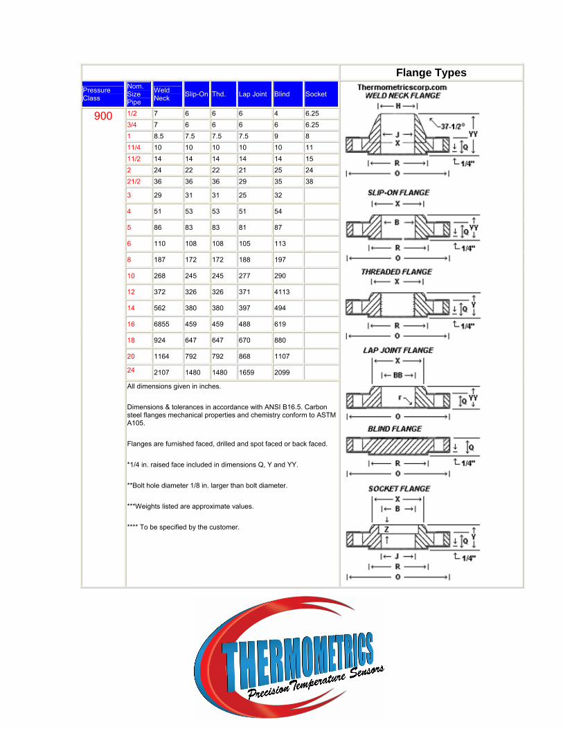
Flange Types Pressure Class
Nom. Size Pipe
Weld Neck Slip-On Thd. Lap Joint Blind Socket
1/2 7 6 6 6 4 6.25 3/4 7 6 6 6 6 6.25 1 8.5 7.5 7.5 7.5 9 8 11/4 10 10 10 10 10 11 11/2 14 14 14 14 14 15 2 24 22 22 21 25 24 21/2 36 36 36 29 35 38 3 29 31 31 25 32 4 51 53 53 51 54 5 86 83 83 81 87 6 110 108 108 105 113 8 187 172 172 188 197 10 268 245 245 277 290 12 372 326 326 371 4113 14 562 380 380 397 494 16 6855 459 459 488 619 18 924 647 647 670 880 20 1164 792 792 868 1107 24 2107 1480 1480 1659 2099
900
All dimensions given in inches.
Dimensions & tolerances in accordance with ANSI B16.5. Carbon steel flanges mechanical properties and chemistry conform to ASTM A105.
Flanges are furnished faced, drilled and spot faced or back faced.
*1/4 in. raised face included in dimensions Q, Y and YY.
**Bolt hole diameter 1/8 in. larger than bolt diameter.
***Weights listed are approximate values.
**** To be specified by the customer.