civil design help- foundation for rotating equipment.pdf
TRANSCRIPT
7/28/2019 Civil Design Help- Foundation for Rotating Equipment.pdf
http://slidepdf.com/reader/full/civil-design-help-foundation-for-rotating-equipmentpdf 1/31
7/28/2019 Civil Design Help- Foundation for Rotating Equipment.pdf
http://slidepdf.com/reader/full/civil-design-help-foundation-for-rotating-equipmentpdf 2/31

7/28/2019 Civil Design Help- Foundation for Rotating Equipment.pdf
http://slidepdf.com/reader/full/civil-design-help-foundation-for-rotating-equipmentpdf 3/31

7/28/2019 Civil Design Help- Foundation for Rotating Equipment.pdf
http://slidepdf.com/reader/full/civil-design-help-foundation-for-rotating-equipmentpdf 4/31
7/28/2019 Civil Design Help- Foundation for Rotating Equipment.pdf
http://slidepdf.com/reader/full/civil-design-help-foundation-for-rotating-equipmentpdf 5/31
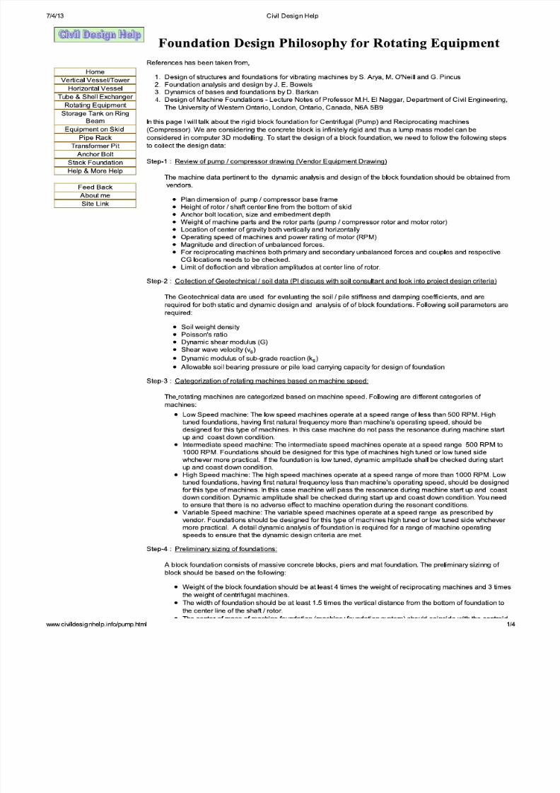
Following tables and graphs are copied from different text booksavailable in the market. Before using these tables and graphs pleasecheck with text books available with you / library.Civildesignhelp.info is not responsible for any error in foundationanalysis and design.
LIST OF SYMBOLS
aMaximum cantilever length (inches); measured from the faceof block to edge of foundation
dMaximum deflection (inches), for estimating the fundamentalnatural frequency of beam or column
e Rotor eccentricity for centrifugal machines
f 1
First coupled natural frequency
f 2
Second coupled natural frequency
f 0 Machine operating speed (cps or rpm)
f d
Damped resonant frequency (cps or rpm)
f n
Undamped natural frequency (cps or rpm)
f’ c
Concrete compressive strength
f y
Yield strength of reinforcement
f nx
Uncoupled natural frequency in translational x direction
f ny
Uncoupled natural frequency in translational y direction
f nz Uncoupled natural frequency in translational z directionsf nφ
Uncoupled natural frequency , rocking about X
f nψ
Uncoupled natural frequency , rocking about Y
f nθ
Uncoupled natural frequency , rocking about z, Torsional
f x,1
Parameters for calculating single pile stiffnesses in horizontal(X),
f z,1
Parameters for calculating single pile stiffnesses in vertical (Z),
f φ,1 Parameters for calculating single pile stiffnesses in rocking (φ)
modes
f x,2
Parameters for calculating single pile damping coefficients inhorizontal (X),
f z,2
Parameters for calculating single pile damping coefficients invertical (Z)
f φ,2 Parameters for calculating single pile damping coefficients in
rocking (φ) modes,
g Acceleration of gravity (32.2 ft/sec2 or 386.4 in/sec2)
Civildesignhelp.info PAGE 1 OF27
7/28/2019 Civil Design Help- Foundation for Rotating Equipment.pdf
http://slidepdf.com/reader/full/civil-design-help-foundation-for-rotating-equipmentpdf 6/31
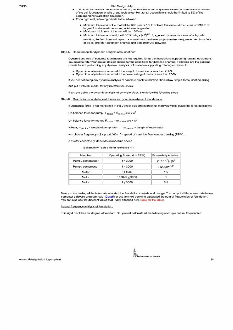
Following tables and graphs are copied from different text booksavailable in the market. Before using these tables and graphs pleasecheck with text books available with you / library.Civildesignhelp.info is not responsible for any error in foundationanalysis and design.
hFoundation embedment depth, the distance between the CGof a machine foundation system and the foundation base.
hi Thickness of ith soil layer
l Embedded length of a pile
m Total mass of a machine foundation system(machine+foundation)
me
Rotor mass for centrifugal machines
r Frequency ratio, defined as f 0/f d (or f 0/f n)
r0
Equivalent radius of foundation; equivalent radius of concrete
pile, pA
π
t Thickness of mat foundation or pile capA
0displacement amplitude
Ai
Stress influence area (spreading below the foundation at aratio of 2 vertical to 1 horizontal) measured at the centroid of ith soil layer
Ap
Cross sectional area of concrete pile
B Foundation width, parallel to the y-axis
B x
Mass ratios for calculating the soil geometrical damping ratiosin horizontal X directions
B
y
Mass ratios for calculating the soil geometrical damping ratios
in horizontal Y directionsB
z Mass ratios for calculating the soil geometrical damping ratios
in vertical Z directions
BBφ
Mass ratios for calculating the soil geometrical damping ratios
in rocking about X (φ) directions
BBψ
Mass ratios for calculating the soil geometrical damping ratiosin rocking about Y (ψ) directions
BBθ
Mass ratios for calculating the soil geometrical damping ratios
in torsional about Z (θ) directions
C x
Damping coefficients for a single pile in horizontal (X)direction
Cz
Damping coefficients for a single pile in vertical (Z) direction
Cφ Damping coefficients for a single pile in rocking about X (φ)directions
DSystem damping or equivalent modal damping ratio for acoupled vibrational motion
D x
Soil or soil-pile damping ratios in horizontal X directions
Civildesignhelp.info PAGE 2 OF27
7/28/2019 Civil Design Help- Foundation for Rotating Equipment.pdf
http://slidepdf.com/reader/full/civil-design-help-foundation-for-rotating-equipmentpdf 7/31
Following tables and graphs are copied from different text booksavailable in the market. Before using these tables and graphs pleasecheck with text books available with you / library.Civildesignhelp.info is not responsible for any error in foundationanalysis and design.
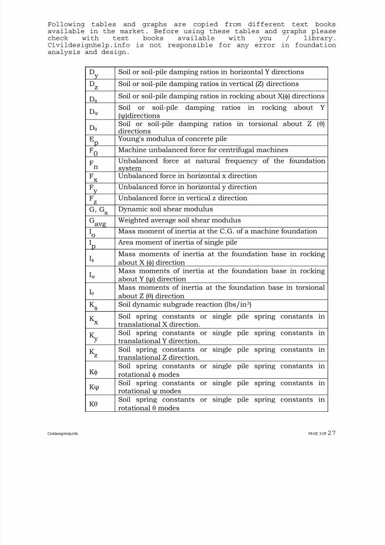
D y
Soil or soil-pile damping ratios in horizontal Y directions
Dz
Soil or soil-pile damping ratios in vertical (Z) directions
Dφ Soil or soil-pile damping ratios in rocking about X(φ) directions
DψSoil or soil-pile damping ratios in rocking about Y(ψ)directions
DθSoil or soil-pile damping ratios in torsional about Z (θ)directions
Ep Young's modulus of concrete pile
F0 Machine unbalanced force for centrifugal machines
Fn
Unbalanced force at natural frequency of the foundationsystem
F x Unbalanced force in horizontal x direction
F y
Unbalanced force in horizontal y direction
Fz Unbalanced force in vertical z direction
G, Gs Dynamic soil shear modulus
Gavg
Weighted average soil shear modulus
Io Mass moment of inertia at the C.G. of a machine foundation
Ip Area moment of inertia of single pile
IφMass moments of inertia at the foundation base in rocking
about X (φ) directionIψ
Mass moments of inertia at the foundation base in rockingabout Y (ψ) direction
IθMass moments of inertia at the foundation base in torsional
about Z (θ) direction
Ks
Soil dynamic subgrade reaction (lbs/in3)
K x
Soil spring constants or single pile spring constants intranslational X direction.
K y
Soil spring constants or single pile spring constants intranslational Y direction.
Kz Soil spring constants or single pile spring constants intranslational Z direction.
Kφ Soil spring constants or single pile spring constants in
rotational φ modes
Kψ Soil spring constants or single pile spring constants inrotational ψ modes
Kθ Soil spring constants or single pile spring constants in
rotational θ modes
Civildesignhelp.info PAGE 3 OF27
7/28/2019 Civil Design Help- Foundation for Rotating Equipment.pdf
http://slidepdf.com/reader/full/civil-design-help-foundation-for-rotating-equipmentpdf 8/31
Following tables and graphs are copied from different text booksavailable in the market. Before using these tables and graphs pleasecheck with text books available with you / library.Civildesignhelp.info is not responsible for any error in foundationanalysis and design.
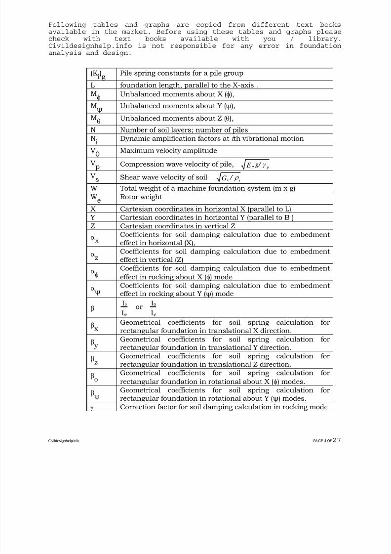
(Ki)g
Pile spring constants for a pile group
L foundation length, parallel to the X-axis .
Mφ Unbalanced moments about X (φ),
Mψ
Unbalanced moments about Y (ψ),
Mθ Unbalanced moments about Z (θ),
N Number of soil layers; number of piles
Ni
Dynamic amplification factors at i th vibrational motion
V0
Maximum velocity amplitude
Vp Compression wave velocity of pile, g/ E p p γ
Vs Shear wave velocity of soil s sG / ρ W Total weight of a machine foundation system (m x g)
We
Rotor weight
X Cartesian coordinates in horizontal X (parallel to L)
Y Cartesian coordinates in horizontal Y (parallel to B )
Z Cartesian coordinates in vertical Z
α x
Coefficients for soil damping calculation due to embedmenteffect in horizontal (X),
αz Coefficients for soil damping calculation due to embedment
effect in vertical (Z)
αφ Coefficients for soil damping calculation due to embedmenteffect in rocking about X (φ) mode
αψ
Coefficients for soil damping calculation due to embedmenteffect in rocking about Y (ψ) mode
β 0I
Iψ
or 0I
Iφ
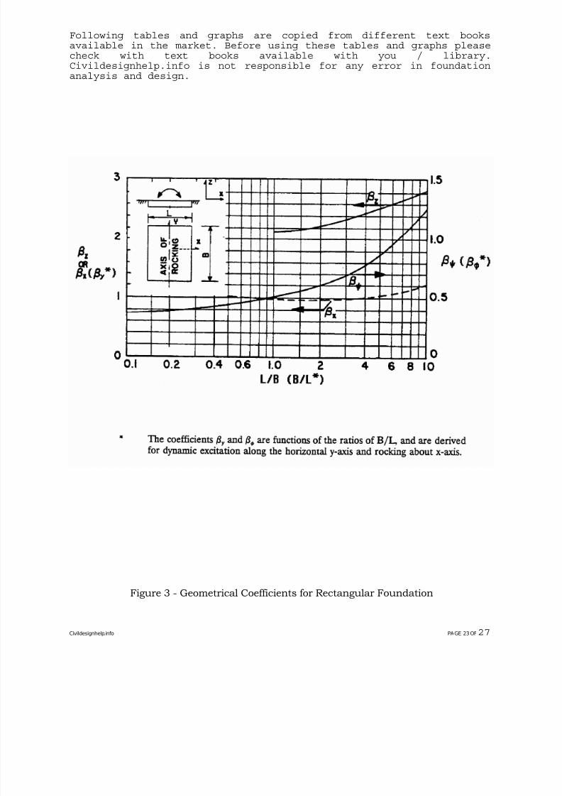
β x
Geometrical coefficients for soil spring calculation forrectangular foundation in translational X direction.
β y
Geometrical coefficients for soil spring calculation forrectangular foundation in translational Y direction.
βz Geometrical coefficients for soil spring calculation forrectangular foundation in translational Z direction.
βφ Geometrical coefficients for soil spring calculation for
rectangular foundation in rotational about X (φ) modes.
βψ
Geometrical coefficients for soil spring calculation forrectangular foundation in rotational about Y (ψ) modes.
γ Correction factor for soil damping calculation in rocking mode
Civildesignhelp.info PAGE 4 OF27
7/28/2019 Civil Design Help- Foundation for Rotating Equipment.pdf
http://slidepdf.com/reader/full/civil-design-help-foundation-for-rotating-equipmentpdf 9/31
Following tables and graphs are copied from different text booksavailable in the market. Before using these tables and graphs pleasecheck with text books available with you / library.Civildesignhelp.info is not responsible for any error in foundationanalysis and design.
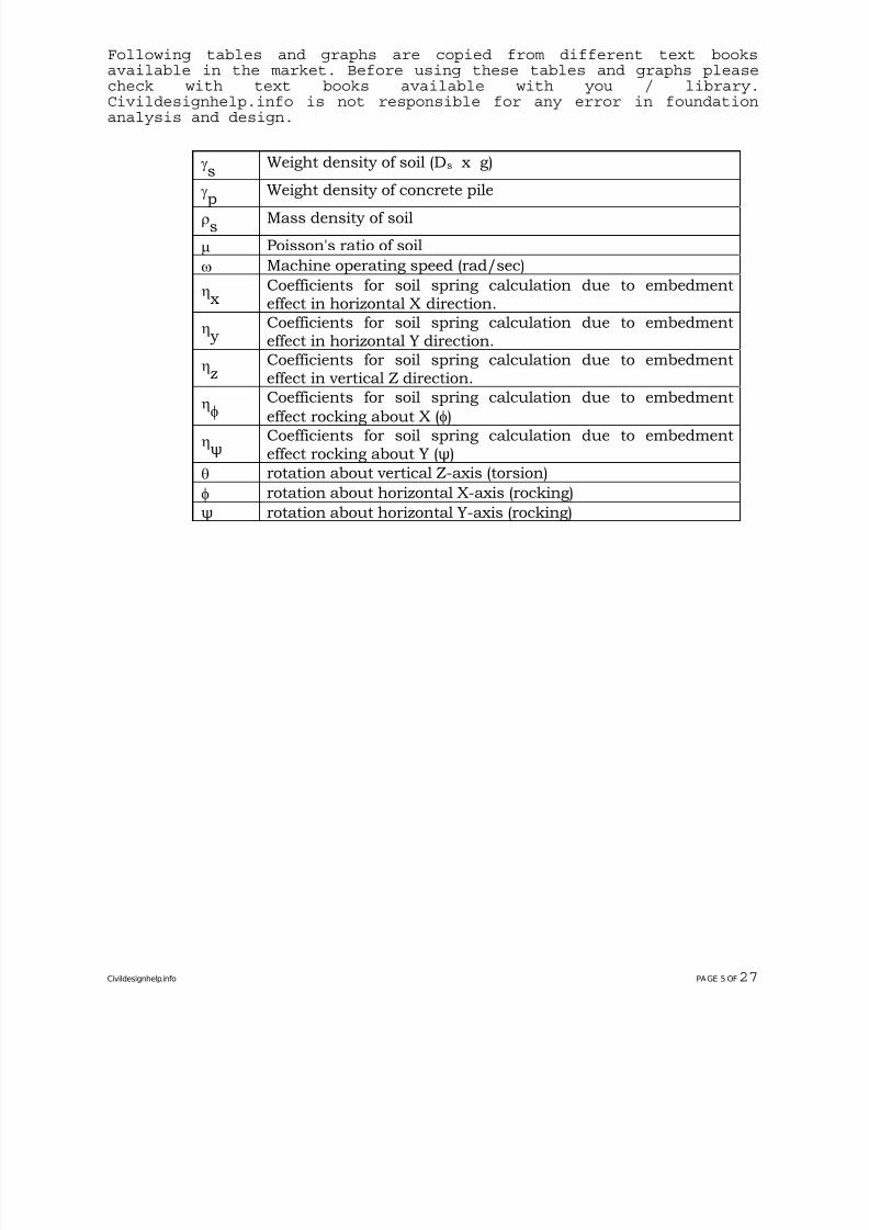
γs Weight density of soil (Ds x g)
γp Weight density of concrete pile
ρs Mass density of soil
μ Poisson's ratio of soil
ω Machine operating speed (rad/sec)
η x
Coefficients for soil spring calculation due to embedmenteffect in horizontal X direction.
η y
Coefficients for soil spring calculation due to embedmenteffect in horizontal Y direction.
ηz Coefficients for soil spring calculation due to embedment
effect in vertical Z direction.
ηφ Coefficients for soil spring calculation due to embedmenteffect rocking about X (φ)
ηψ
Coefficients for soil spring calculation due to embedmenteffect rocking about Y (ψ)
θ rotation about vertical Z-axis (torsion)
φ rotation about horizontal X-axis (rocking)
ψ rotation about horizontal Y-axis (rocking)
Civildesignhelp.info PAGE 5 OF27
7/28/2019 Civil Design Help- Foundation for Rotating Equipment.pdf
http://slidepdf.com/reader/full/civil-design-help-foundation-for-rotating-equipmentpdf 10/31
Following tables and graphs are copied from different text booksavailable in the market. Before using these tables and graphs pleasecheck with text books available with you / library.Civildesignhelp.info is not responsible for any error in foundationanalysis and design.
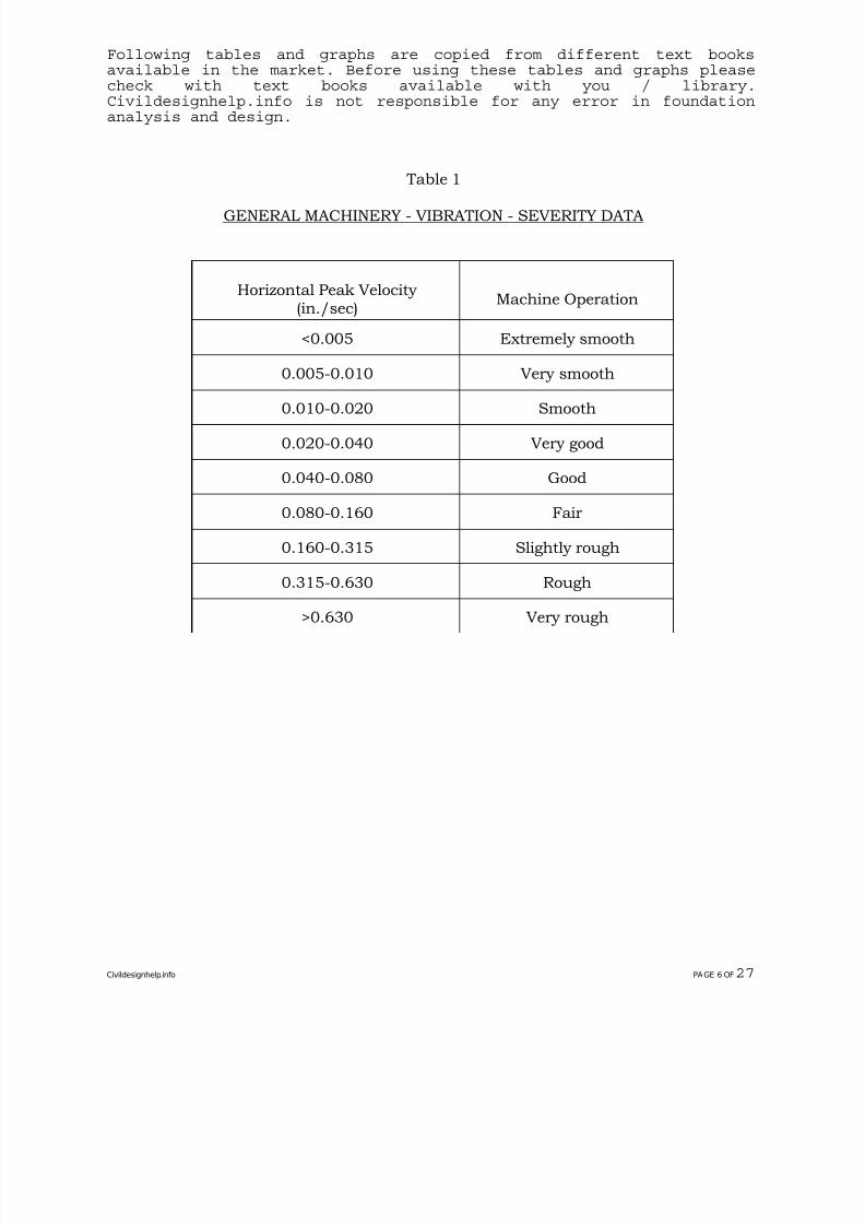
Table 1
GENERAL MACHINERY - VIBRATION - SEVERITY DATA
Horizontal Peak Velocity (in./sec)
Machine Operation
<0.005 Extremely smooth
0.005-0.010 Very smooth
0.010-0.020 Smooth
0.020-0.040 Very good
0.040-0.080 Good
0.080-0.160 Fair
0.160-0.315 Slightly rough
0.315-0.630 Rough
>0.630 Very rough
Civildesignhelp.info PAGE 6 OF27
7/28/2019 Civil Design Help- Foundation for Rotating Equipment.pdf
http://slidepdf.com/reader/full/civil-design-help-foundation-for-rotating-equipmentpdf 11/31
Following tables and graphs are copied from different text booksavailable in the market. Before using these tables and graphs pleasecheck with text books available with you / library.Civildesignhelp.info is not responsible for any error in foundationanalysis and design.
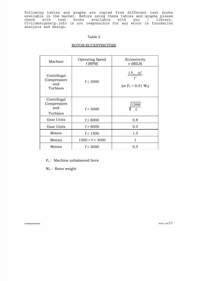
Table 2
ROTOR ECCENTRICITIES
MachineOperating Speed
f (RPM)Eccentricity
e (MILS)
CentrifugalCompressors
and Turbines
f ≤ 3000
1.8 _ 107
2f
(or Fo = 0.51 We)
CentrifugalCompressors
and
Turbinesf > 3000
12000
f
Gear Units f ≤ 8000 0.8
Gear Units f > 8000 0.5
Motors f ≤ 1500 1.5
Motors 1500 < f < 3000 1
Motors f ≥ 3000 0.5
Fo : Machine unbalanced force
We : Rotor weight
Civildesignhelp.info PAGE 7 OF27
7/28/2019 Civil Design Help- Foundation for Rotating Equipment.pdf
http://slidepdf.com/reader/full/civil-design-help-foundation-for-rotating-equipmentpdf 12/31
Following tables and graphs are copied from different text booksavailable in the market. Before using these tables and graphs pleasecheck with text books available with you / library.Civildesignhelp.info is not responsible for any error in foundationanalysis and design.
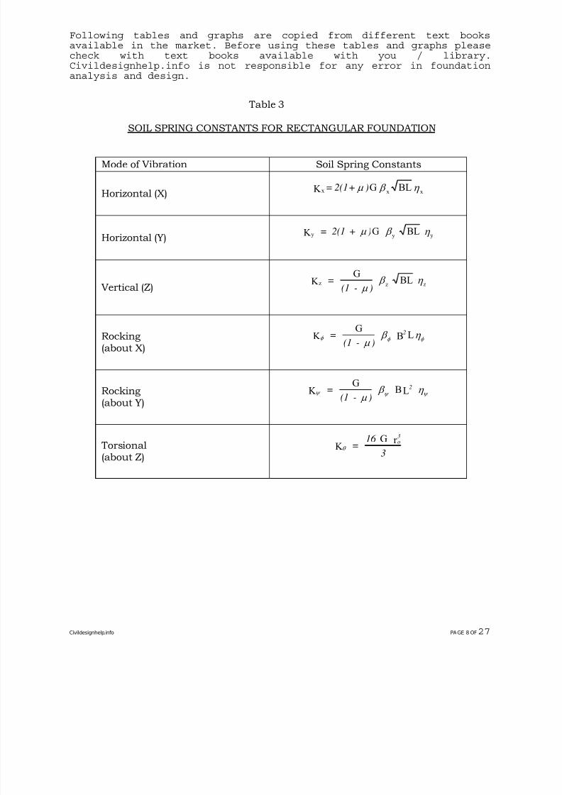
Table 3
SOIL SPRING CONSTANTS FOR RECTANGULAR FOUNDATION
Mode of Vibration Soil Spring Constants
Horizontal (X)η β μ
xxx BLGK )+2(1=
Horizontal (Y) y y yK G BL= 2(1 + )μ β η
Vertical (Z)z z zK
GBL=
(1 - )
μ β η
Rocking(about X)
φ φ φ μ
β η K G
B L=(1 - )
2
Rocking(about Y)
ψ ψ ψ μ
β η K G BL=(1 - )
2
Torsional(about Z)
θ K G r
=16
3
o3
Civildesignhelp.info PAGE 8 OF27
7/28/2019 Civil Design Help- Foundation for Rotating Equipment.pdf
http://slidepdf.com/reader/full/civil-design-help-foundation-for-rotating-equipmentpdf 13/31
Following tables and graphs are copied from different text booksavailable in the market. Before using these tables and graphs pleasecheck with text books available with you / library.Civildesignhelp.info is not responsible for any error in foundationanalysis and design.
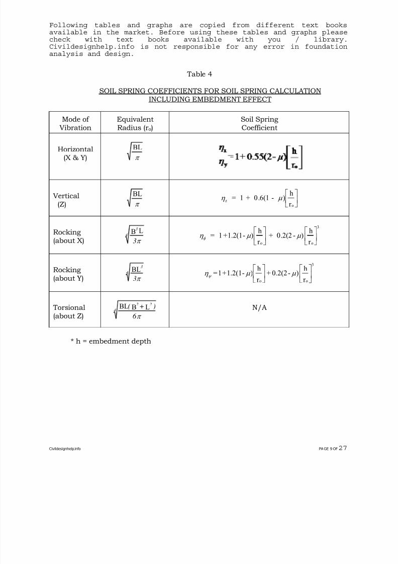
Table 4
SOIL SPRING COEFFICIENTS FOR SOIL SPRING CALCULATIONINCLUDING EMBEDMENT EFFECT
Mode of Vibration
EquivalentRadius (ro)
Soil SpringCoefficient
Horizontal(X & Y)
BL
π
Vertical(Z)
BL
π z
o
= 1 + 0.6(1 - )h
r η μ
⎡
⎣⎢
⎤
⎦⎥
Rocking(about X)
3
4
3
B L
π
φ η μ μ = 1 +1.2(1- )h
r + 0.2(2 - )
h
r o
3
o
⎡
⎣⎢
⎤
⎦⎥
⎡
⎣⎢
⎤
⎦⎥
Rocking(about Y)4
3
3π
BL ⎥⎦
⎤⎢⎣
⎡⎥⎦
⎤⎢⎣
⎡
r
h)-0.2(2+r
h)-1.2(1+1=
o
3
oμ μ η ψ
Torsional(about Z)
4
22
6
)+(
π
LBBL N/A
* h = embedment depth
Civildesignhelp.info PAGE 9 OF27
7/28/2019 Civil Design Help- Foundation for Rotating Equipment.pdf
http://slidepdf.com/reader/full/civil-design-help-foundation-for-rotating-equipmentpdf 14/31
Following tables and graphs are copied from different text booksavailable in the market. Before using these tables and graphs pleasecheck with text books available with you / library.Civildesignhelp.info is not responsible for any error in foundationanalysis and design.
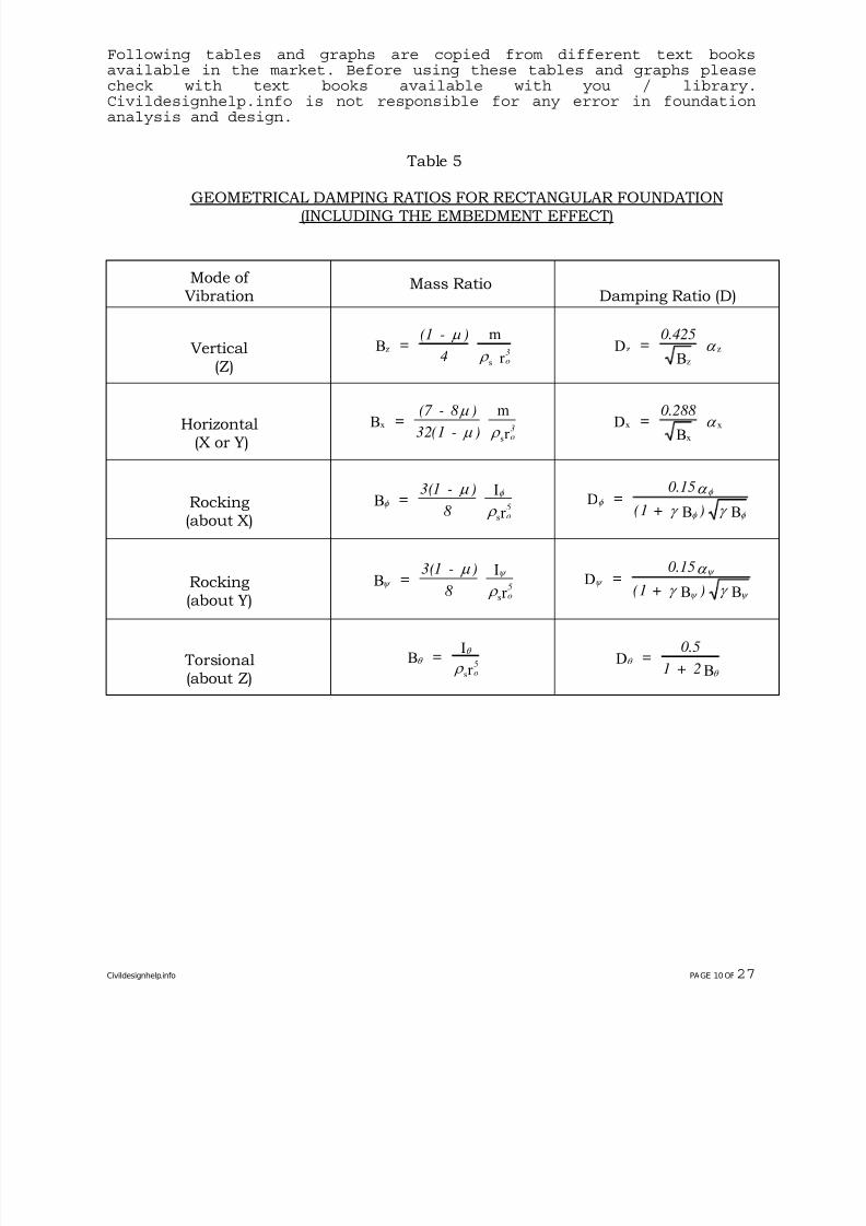
Table 5
GEOMETRICAL DAMPING RATIOS FOR RECTANGULAR FOUNDATION(INCLUDING THE EMBEDMENT EFFECT)
Mode of Vibration
Mass RatioDamping Ratio (D)
Vertical(Z)
z
s
Bm
r =
(1 - )
4
o3
μ
ρ z
z
zDB
=0.425
α
Horizontal(X or Y)
x
s
Bm
r =
(7 - 8 )
32(1 - )
o3
μ
μ ρ x
x
xDB
=0.288
α
Rocking(about X)
φ
φ μ
ρ B
I
r s
=3(1 - )
8
o5 φ
φ
φ φ
α
γ γ D
B B=
0.15
(1 + )
Rocking
(about Y)
ψ
ψ μ
ρ
BI
r s
=3(1 - )
8
o
5 ψ
ψ
ψ ψ
α
γ γ
D
B B
=0.15
(1 + )
Torsional(about Z)
θ θ
ρ B
I
r s
=o5 θ
θ
DB
=0.5
1 + 2
Civildesignhelp.info PAGE 10 OF27
7/28/2019 Civil Design Help- Foundation for Rotating Equipment.pdf
http://slidepdf.com/reader/full/civil-design-help-foundation-for-rotating-equipmentpdf 15/31
Following tables and graphs are copied from different text booksavailable in the market. Before using these tables and graphs pleasecheck with text books available with you / library.Civildesignhelp.info is not responsible for any error in foundationanalysis and design.
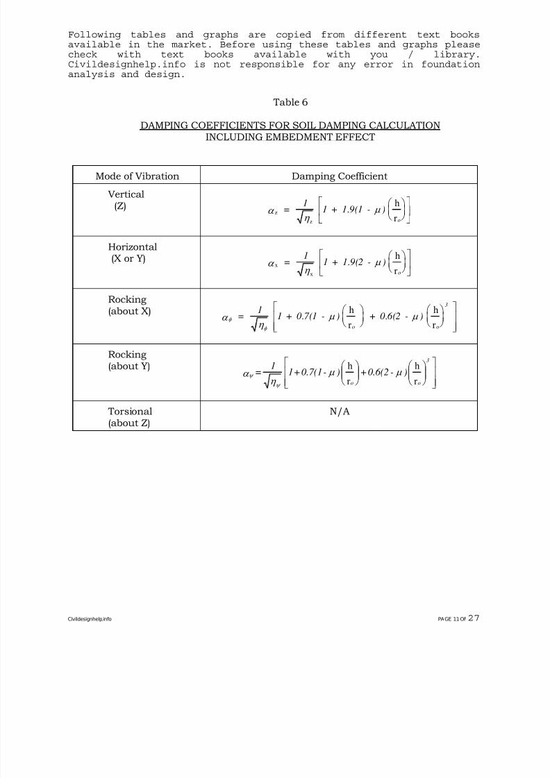
Table 6
DAMPING COEFFICIENTS FOR SOIL DAMPING CALCULATIONINCLUDING EMBEDMENT EFFECT
Mode of Vibration Damping Coefficient
Vertical(Z)
z
z
h
r α
η μ =
11 + 1.9(1 - )
o
⎛ ⎝ ⎜
⎞ ⎠⎟
⎡
⎣⎢
⎤
⎦⎥
Horizontal(X or Y)x
x
h
r α
η μ =
11 + 1.9(2 - )
o
⎛ ⎝ ⎜
⎞ ⎠⎟
⎡
⎣⎢
⎤
⎦⎥
Rocking(about X)
φ
φ
α η
μ μ =1
1 + 0.7(1 - ) + 0.6(2 - )o
3
o
h
r
h
r
⎛ ⎝ ⎜
⎞ ⎠⎟
⎛ ⎝ ⎜
⎞ ⎠⎟
⎡
⎣⎢⎢
⎤
⎦⎥⎥
Rocking(about Y)
⎥⎥⎦
⎤
⎢⎢⎣
⎡
⎟⎟ ⎠
⎞
⎜⎜⎝
⎛
⎟⎟ ⎠
⎞
⎜⎜⎝
⎛ )-0.6(2+)-0.7(1+1
1 =
o
3
o r
h
r
hμ μ
η α ψ ψ
Torsional(about Z)
N/A
Civildesignhelp.info PAGE 11 OF27
7/28/2019 Civil Design Help- Foundation for Rotating Equipment.pdf
http://slidepdf.com/reader/full/civil-design-help-foundation-for-rotating-equipmentpdf 16/31
Following tables and graphs are copied from different text booksavailable in the market. Before using these tables and graphs pleasecheck with text books available with you / library.Civildesignhelp.info is not responsible for any error in foundationanalysis and design.
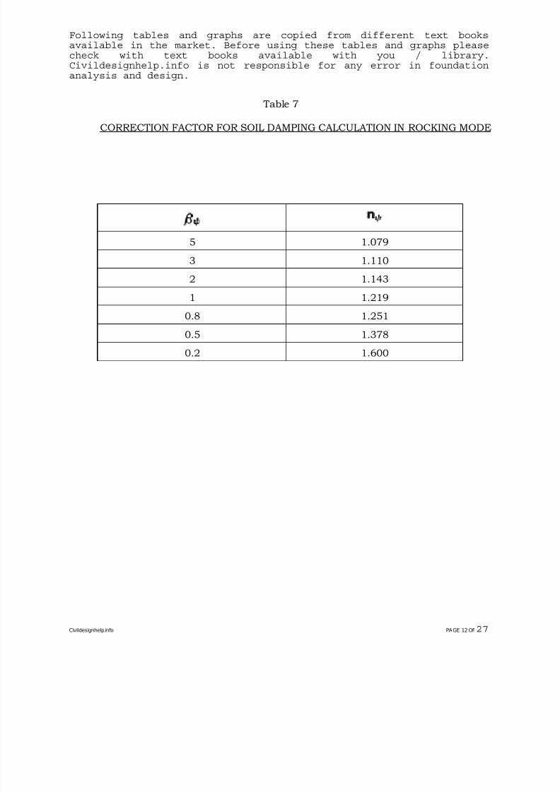
Table 7
CORRECTION FACTOR FOR SOIL DAMPING CALCULATION IN ROCKING MODE
5 1.079
3 1.110
2 1.143
1 1.219
0.8 1.251
0.5 1.378
0.2 1.600
Civildesignhelp.info PAGE 12 OF27
7/28/2019 Civil Design Help- Foundation for Rotating Equipment.pdf
http://slidepdf.com/reader/full/civil-design-help-foundation-for-rotating-equipmentpdf 17/31
7/28/2019 Civil Design Help- Foundation for Rotating Equipment.pdf
http://slidepdf.com/reader/full/civil-design-help-foundation-for-rotating-equipmentpdf 18/31
Following tables and graphs are copied from different text booksavailable in the market. Before using these tables and graphs pleasecheck with text books available with you / library.Civildesignhelp.info is not responsible for any error in foundationanalysis and design.
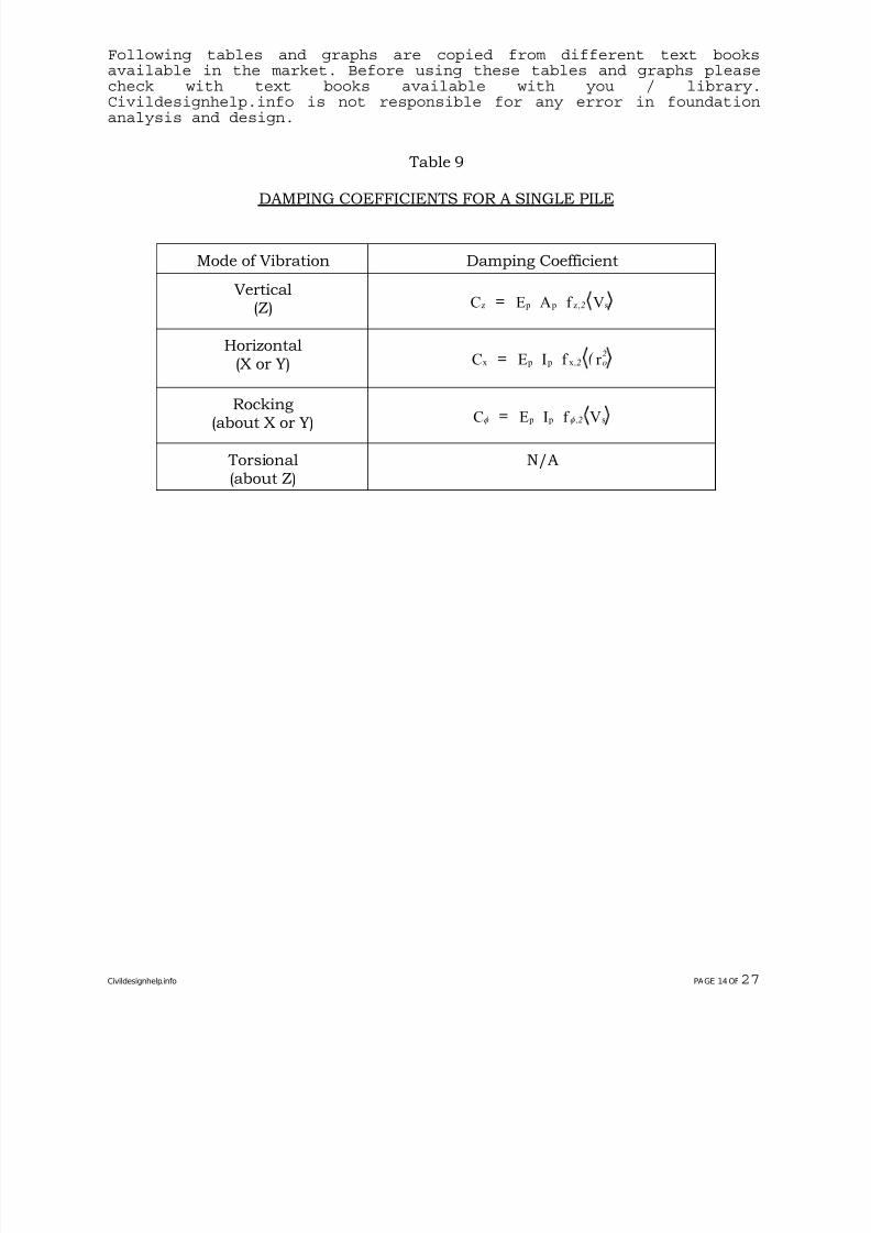
Table 9
DAMPING COEFFICIENTS FOR A SINGLE PILE
Mode of Vibration Damping Coefficient
Vertical(Z) z p p zC E A f V= ,2 s
Horizontal(X or Y) x p p xC E I f r = ( ,2 o
2
Rocking(about X or Y) φ φ C E I f V p p s= ,2
Torsional(about Z)
N/A
Civildesignhelp.info PAGE 14 OF27
7/28/2019 Civil Design Help- Foundation for Rotating Equipment.pdf
http://slidepdf.com/reader/full/civil-design-help-foundation-for-rotating-equipmentpdf 19/31
Following tables and graphs are copied from different text booksavailable in the market. Before using these tables and graphs pleasecheck with text books available with you / library.Civildesignhelp.info is not responsible for any error in foundationanalysis and design.
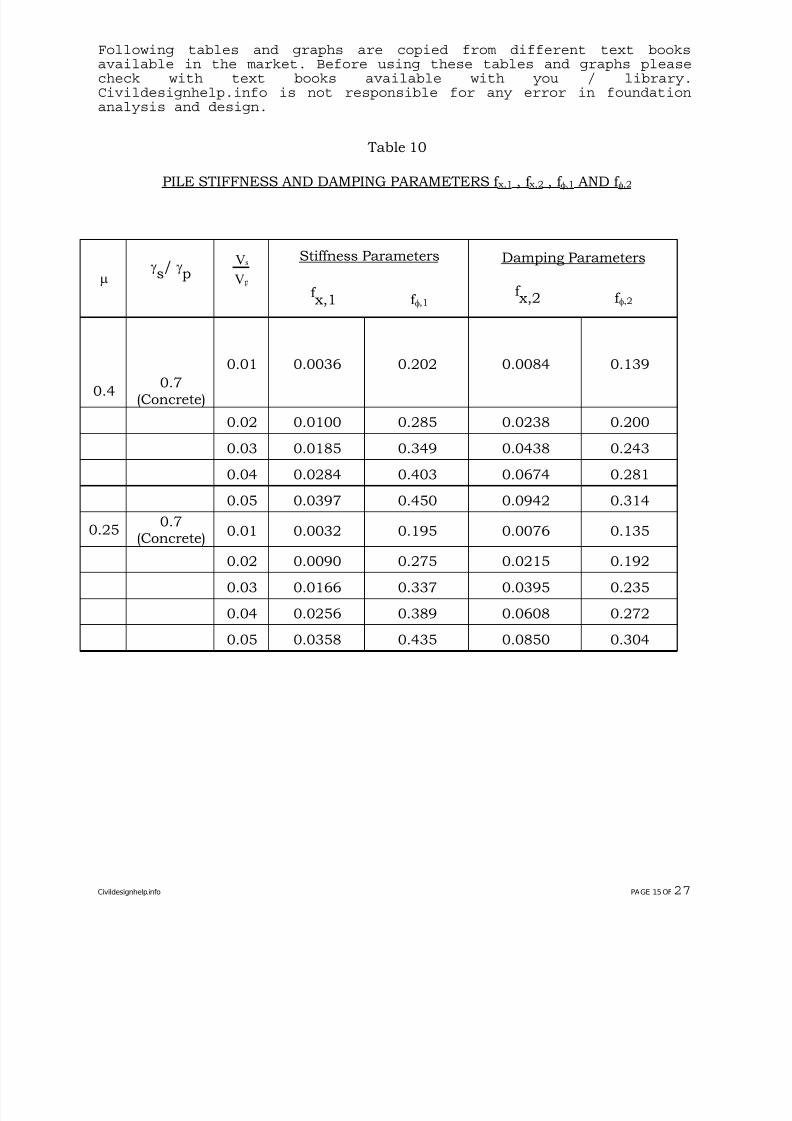
Table 10
PILE STIFFNESS AND DAMPING PARAMETERS f x,1 , f x,2 , f φ,1 AND f φ,2
μ γs/ γ
p s
p
V
V
Stiffness Parameters
f x,1 f φ,1
Damping Parameters
f x,2 f φ,2
0.40.7
(Concrete)
0.01 0.0036 0.202 0.0084 0.139
0.02 0.0100 0.285 0.0238 0.200
0.03 0.0185 0.349 0.0438 0.243
0.04 0.0284 0.403 0.0674 0.281
0.05 0.0397 0.450 0.0942 0.314
0.250.7
(Concrete)
0.01 0.0032 0.195 0.0076 0.135
0.02 0.0090 0.275 0.0215 0.192
0.03 0.0166 0.337 0.0395 0.235
0.04 0.0256 0.389 0.0608 0.272
0.05 0.0358 0.435 0.0850 0.304
Civildesignhelp.info PAGE 15 OF27
7/28/2019 Civil Design Help- Foundation for Rotating Equipment.pdf
http://slidepdf.com/reader/full/civil-design-help-foundation-for-rotating-equipmentpdf 20/31
Following tables and graphs are copied from different text booksavailable in the market. Before using these tables and graphs pleasecheck with text books available with you / library.Civildesignhelp.info is not responsible for any error in foundationanalysis and design.
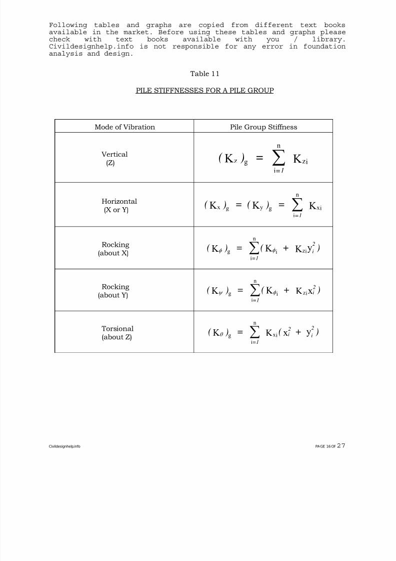
Table 11
PILE STIFFNESSES FOR A PILE GROUP
Mode of Vibration Pile Group Stiffness
Vertical(Z)
( ) ==1
z g
i
n
izK K ∑
Horizontal(X or Y)
(
) = ( ) ==1
x g y g
i
n
ixK K K ∑
Rocking(about X)
( ) = ( + )=1
i
2
φ φ K K K yg
i
n
i iz∑
Rocking(about Y)
( ) = ( + )=1
i2
ψ φ K K K xg
i
n
i iz∑
Torsional(about Z)
( ) = ( + )=1
i2
i
2
θ K K x yg
i
n
ix∑
Civildesignhelp.info PAGE 16 OF27
7/28/2019 Civil Design Help- Foundation for Rotating Equipment.pdf
http://slidepdf.com/reader/full/civil-design-help-foundation-for-rotating-equipmentpdf 21/31
Following tables and graphs are copied from different text booksavailable in the market. Before using these tables and graphs pleasecheck with text books available with you / library.Civildesignhelp.info is not responsible for any error in foundationanalysis and design.
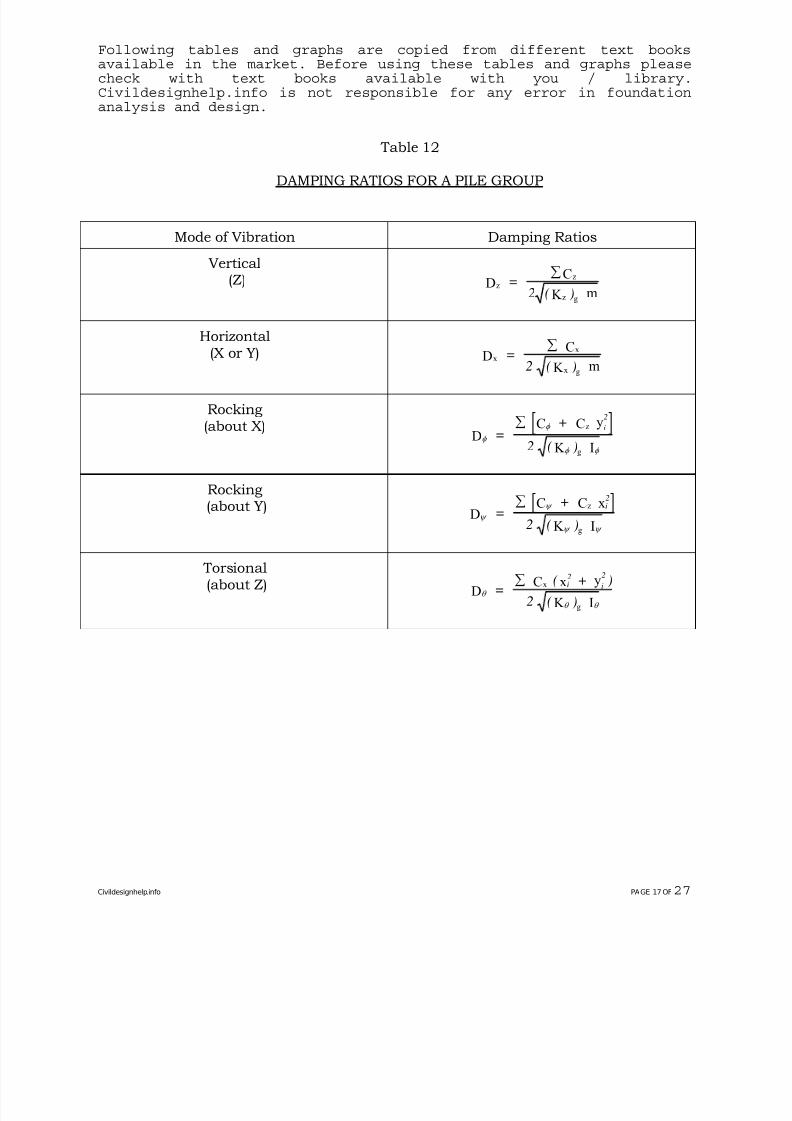
Table 12
DAMPING RATIOS FOR A PILE GROUP
Mode of Vibration Damping Ratios
Vertical(Z) z
z
z g
DC
K m=
2 ( )
∑
Horizontal(X or Y)
x
x
x gD
C
K m=
2 ( )
∑
Rocking(about X) [ ]
φ
φ
φ φ
DC C y
K I
z
g
=+
2 ( )
i
2∑
Rocking(about Y) [ ]
ψ
ψ
ψ ψ
DC C x
K I
z
g
=+
2 ( )
i2∑
Torsional(about Z)
θ
θ θ
DC x y
K I
x
g
=( + )
2 ( )
i2
i
2∑
Civildesignhelp.info PAGE 17 OF27
7/28/2019 Civil Design Help- Foundation for Rotating Equipment.pdf
http://slidepdf.com/reader/full/civil-design-help-foundation-for-rotating-equipmentpdf 22/31
7/28/2019 Civil Design Help- Foundation for Rotating Equipment.pdf
http://slidepdf.com/reader/full/civil-design-help-foundation-for-rotating-equipmentpdf 23/31
Following tables and graphs are copied from different text booksavailable in the market. Before using these tables and graphs pleasecheck with text books available with you / library.Civildesignhelp.info is not responsible for any error in foundationanalysis and design.
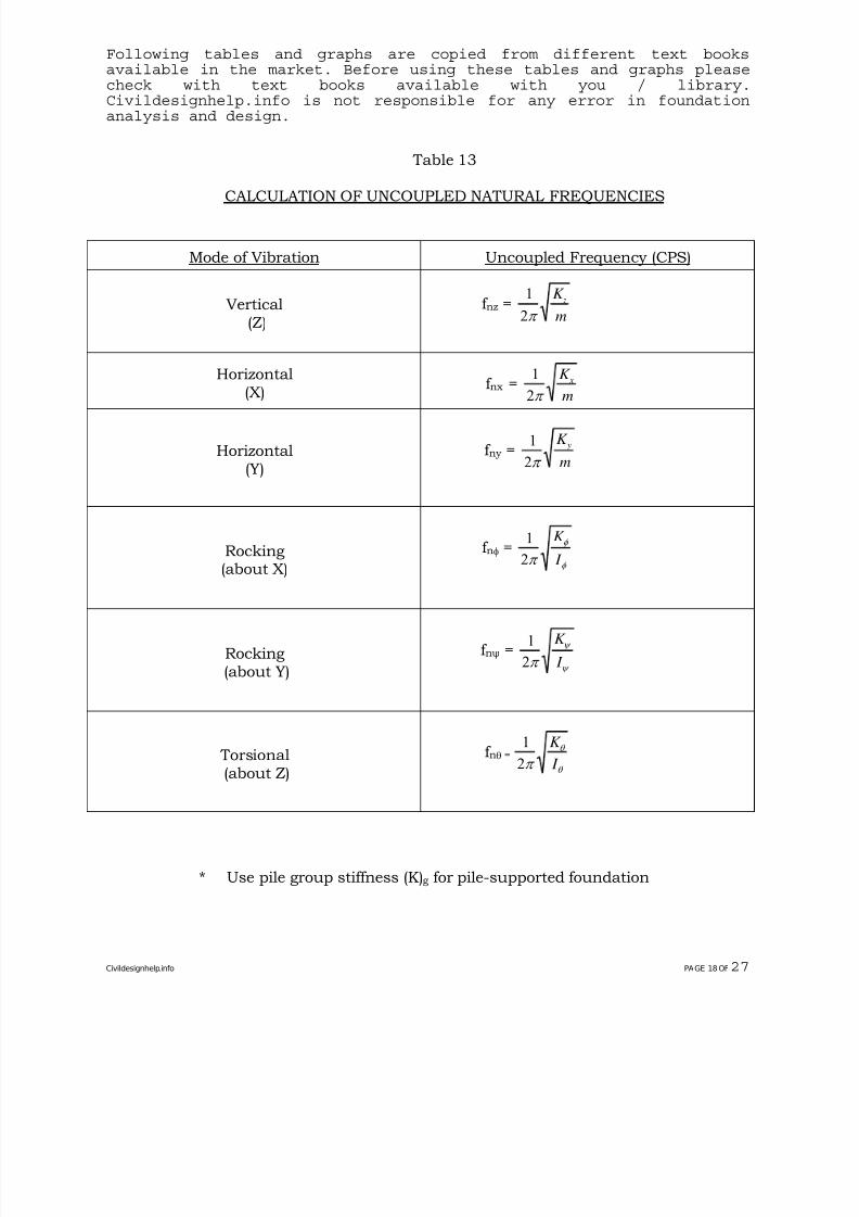
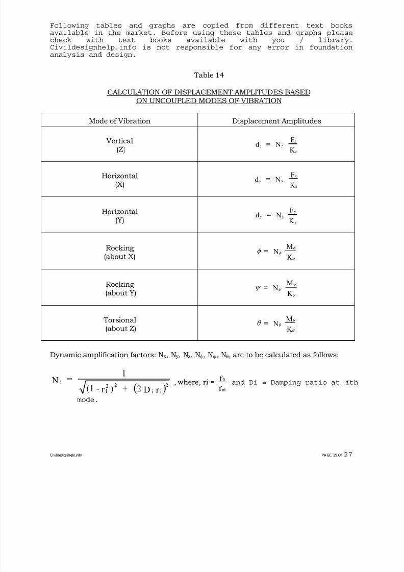
Table 14
CALCULATION OF DISPLACEMENT AMPLITUDES BASEDON UNCOUPLED MODES OF VIBRATION
Mode of Vibration Displacement Amplitudes
Vertical(Z)
z z z
z
=d NF
K
Horizontal
(X) x x
x
x
=d NF
K
Horizontal(Y)
y y
y
y
=d NF
K
Rocking(about X)
φ φ
φ
φ
= NM
K
Rocking(about Y)
ψ ψ
ψ
ψ
= NM
K
Torsional(about Z)
θ θ θ
θ
= NM
K
Dynamic amplification factors: N x, N y , Nz, Nφ, Nψ, Nθ, are to be calculated as follows:
( )r D2 + )r -(1
1 = N
ii
222i
i , where, ri =0
ni
f
f and Di = Damping ratio at ith
mode.
Civildesignhelp.info PAGE 19 OF27
7/28/2019 Civil Design Help- Foundation for Rotating Equipment.pdf
http://slidepdf.com/reader/full/civil-design-help-foundation-for-rotating-equipmentpdf 24/31
Following tables and graphs are copied from different text booksavailable in the market. Before using these tables and graphs pleasecheck with text books available with you / library.Civildesignhelp.info is not responsible for any error in foundationanalysis and design.
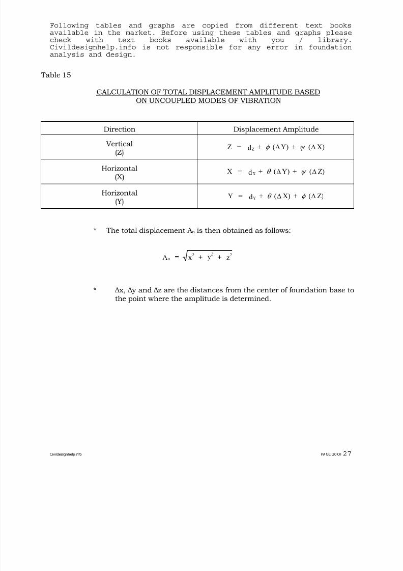
Table 15
CALCULATION OF TOTAL DISPLACEMENT AMPLITUDE BASEDON UNCOUPLED MODES OF VIBRATION
Direction Displacement Amplitude
Vertical(Z)
Z = d + ( Y) + ( X)Z φ ψ Δ Δ
Horizontal(X)
X = d + ( Y) + ( Z)X θ ψ Δ Δ
Horizontal(Y)
Y = d + ( X) + ( Z)Y θ φ Δ Δ
* The total displacement Ao is then obtained as follows:
o2 2 2= + +A x y z
* Δ x, Δ y and Δz are the distances from the center of foundation base tothe point where the amplitude is determined.
Civildesignhelp.info PAGE 20 OF27
7/28/2019 Civil Design Help- Foundation for Rotating Equipment.pdf
http://slidepdf.com/reader/full/civil-design-help-foundation-for-rotating-equipmentpdf 25/31
Following tables and graphs are copied from different text booksavailable in the market. Before using these tables and graphs pleasecheck with text books available with you / library.Civildesignhelp.info is not responsible for any error in foundationanalysis and design.
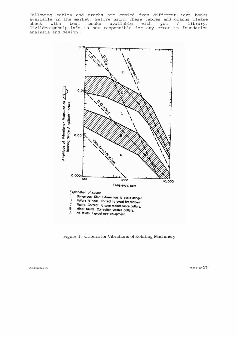
Figure 1: Criteria for Vibrations of Rotating Machinery
Civildesignhelp.info PAGE 21 OF27
7/28/2019 Civil Design Help- Foundation for Rotating Equipment.pdf
http://slidepdf.com/reader/full/civil-design-help-foundation-for-rotating-equipmentpdf 26/31
Following tables and graphs are copied from different text booksavailable in the market. Before using these tables and graphs pleasecheck with text books available with you / library.Civildesignhelp.info is not responsible for any error in foundationanalysis and design.
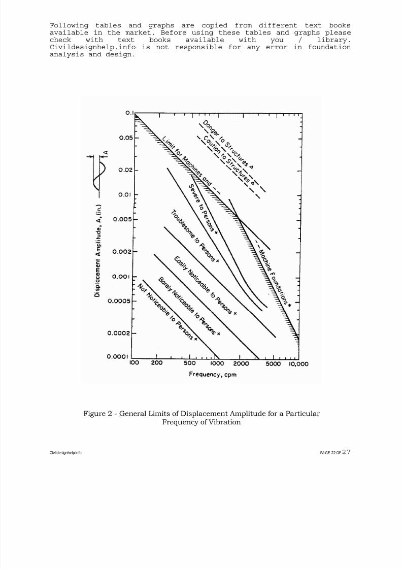
Figure 2 - General Limits of Displacement Amplitude for a ParticularFrequency of Vibration
Civildesignhelp.info PAGE 22 OF27
7/28/2019 Civil Design Help- Foundation for Rotating Equipment.pdf
http://slidepdf.com/reader/full/civil-design-help-foundation-for-rotating-equipmentpdf 27/31
Following tables and graphs are copied from different text booksavailable in the market. Before using these tables and graphs pleasecheck with text books available with you / library.Civildesignhelp.info is not responsible for any error in foundationanalysis and design.
Figure 3 - Geometrical Coefficients for Rectangular Foundation
Civildesignhelp.info PAGE 23 OF27
7/28/2019 Civil Design Help- Foundation for Rotating Equipment.pdf
http://slidepdf.com/reader/full/civil-design-help-foundation-for-rotating-equipmentpdf 28/31
Following tables and graphs are copied from different text booksavailable in the market. Before using these tables and graphs pleasecheck with text books available with you / library.Civildesignhelp.info is not responsible for any error in foundationanalysis and design.
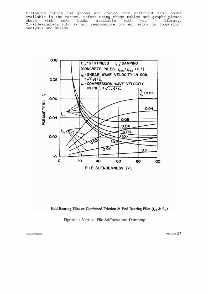
Figure 4: Vertical Pile Stiffness and Damping
Civildesignhelp.info PAGE 24 OF27
7/28/2019 Civil Design Help- Foundation for Rotating Equipment.pdf
http://slidepdf.com/reader/full/civil-design-help-foundation-for-rotating-equipmentpdf 29/31
Following tables and graphs are copied from different text booksavailable in the market. Before using these tables and graphs pleasecheck with text books available with you / library.Civildesignhelp.info is not responsible for any error in foundationanalysis and design.
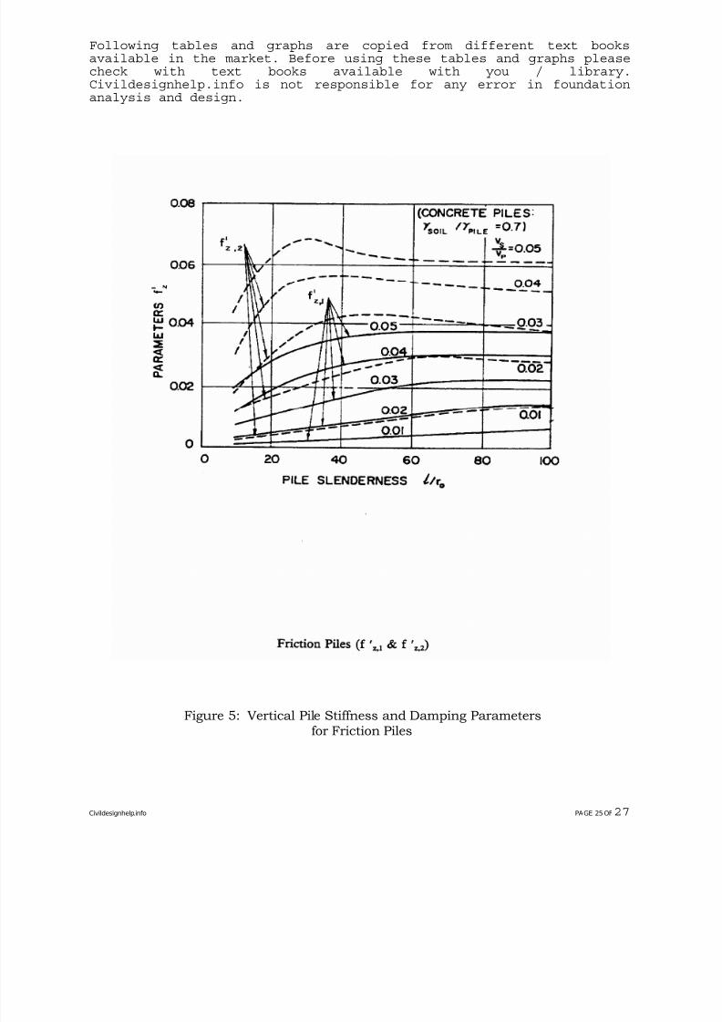
Figure 5: Vertical Pile Stiffness and Damping Parametersfor Friction Piles
Civildesignhelp.info PAGE 25 OF27
7/28/2019 Civil Design Help- Foundation for Rotating Equipment.pdf
http://slidepdf.com/reader/full/civil-design-help-foundation-for-rotating-equipmentpdf 30/31
Following tables and graphs are copied from different text booksavailable in the market. Before using these tables and graphs pleasecheck with text books available with you / library.Civildesignhelp.info is not responsible for any error in foundationanalysis and design.
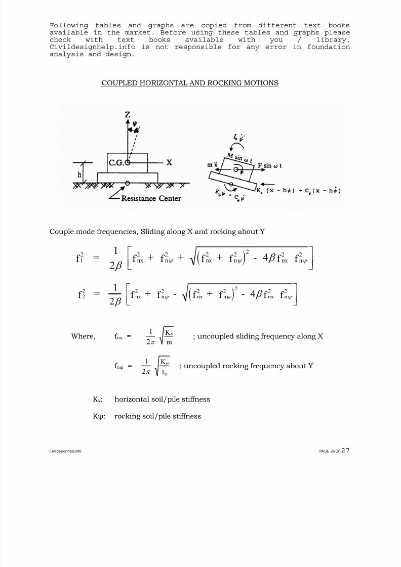
COUPLED HORIZONTAL AND ROCKING MOTIONS
Couple mode frequencies, Sliding along X and rocking about Y
( )12
nx2
n2
2
nx2
n2
nx2
n2
f =1
2 f + f + f + f - 4 f f
β β ψ ψ
⎡⎣⎢
⎤⎦⎥
ψ
( )22
nx2
n2 2
nx2
n2
nx2
n2
f =1
2 f + f - f + f - 4 f f
β β ψ ψ
⎡⎣⎢
⎤⎦⎥
ψ
Where, f nx =1
2
K
m
x
π ; uncoupled sliding frequency along X
f nψ =1
2 K
Iπ
ψ
ψ ; uncoupled rocking frequency about Y
K x: horizontal soil/pile stiffness
Kψ: rocking soil/pile stiffness
Civildesignhelp.info PAGE 26 OF27
7/28/2019 Civil Design Help- Foundation for Rotating Equipment.pdf
http://slidepdf.com/reader/full/civil-design-help-foundation-for-rotating-equipmentpdf 31/31
Following tables and graphs are copied from different text booksavailable in the market. Before using these tables and graphs pleasecheck with text books available with you / library.Civildesignhelp.info is not responsible for any error in foundationanalysis and design.
m: total mass of a machine foundation system
Iψ: Io + mh2, the mass moment of inertia at the foundation base
Io: the mass moment of inertia at the C.G. of a machinefoundation system
h: the distance between combined C.G. and the base of amachine foundation
β = 0I
Iψ
Note that the coupling effect becomes insignificant and can be neglected whenthe two coupled frequencies are determined to be away from the machineoperating speed by at least 40%.