cisco systems 5508 wireless lan controller · pdf fileradius ike session encryption key, ike...
TRANSCRIPT
© Copyright 2012 Cisco Systems, Inc. This document may be freely reproduced and distributed whole and intact including this Copyright Notice.
1
Cisco Systems 5508 Wireless LAN Controller
FIPS 140-2 Non Proprietary Security Policy Level 2 Validation
Version 0.8
August 31, 2015
© Copyright 2012 Cisco Systems, Inc. This document may be freely reproduced and distributed whole and intact including this Copyright Notice.
2
Table of Contents
1 INTRODUCTION .................................................................................................................. 3
1.1 PURPOSE ............................................................................................................................. 31.2 MODELS ............................................................................................................................. 31.3 MODULE VALIDATION LEVEL ............................................................................................ 31.4 REFERENCES ....................................................................................................................... 31.5 TERMINOLOGY ................................................................................................................... 41.6 DOCUMENT ORGANIZATION ............................................................................................... 4
2 CISCO SYSTEMS 5508 WIRELESS LAN CONTROLLER ............................................ 5
2.1 CRYPTOGRAPHIC MODULE PHYSICAL CHARACTERISTICS .................................................. 52.2 MODULE INTERFACES ......................................................................................................... 52.3 ROLES, SERVICES AND AUTHENTICATION .......................................................................... 72.4 SERVICES AVAILABLE IN A NON-FIPS MODE OF OPERATION ............................................ 92.5 UNAUTHENTICATED SERVICES ........................................................................................... 92.6 PHYSICAL SECURITY ........................................................................................................ 102.7 CRYPTOGRAPHIC ALGORITHMS ........................................................................................ 122.8 CRYPTOGRAPHIC KEY MANAGEMENT .............................................................................. 132.9 SELF-TESTS ...................................................................................................................... 182.10 SELF-TESTS PERFORMED ................................................................................................... 18
3 SECURE OPERATION ..................................................................................................... 19
© Copyright 2012 Cisco Systems, Inc. This document may be freely reproduced and distributed whole and intact including this Copyright Notice.
3
1 Introduction
1.1 Purpose This is a non-proprietary Cryptographic Module Security Policy for the Cisco Systems 5508 Wireless LAN Controller, Firmware 8.0 with SNMP Stack v15.3, OPENSSL-0.9.8g-8.0.0, QUICKSEC-2.0-8.0 and FP-CRYPTO-7.0.0; referred to in this document as controller or the module. This security policy describes how the modules meet the security requirements of FIPS 140-2 Level 2 and how to run the modules in a FIPS 140-2 mode of operation and may be freely distributed.
1.2 Model Cisco Systems 5508 Wireless LAN Controller
FIPS 140-2 (Federal Information Processing Standards Publication 140-2 — Security Requirements for Cryptographic Modules) details the U.S. Government requirements for cryptographic modules. More information about the FIPS 140-2 standard and validation program is available on the NIST website at http://csrc.nist.gov/groups/STM/index.html.
1.3 Module Validation Level
The following table lists the level of validation for each area in the FIPS PUB 140-2.
No. Area Title Level 1 Cryptographic Module Specification 2 2 Cryptographic Module Ports and Interfaces 2 3 Roles, Services, and Authentication 2 4 Finite State Model 2 5 Physical Security 2 6 Operational Environment N/A 7 Cryptographic Key management 2 8 Electromagnetic Interface/Electromagnetic Compatibility 2 9 Self-Tests 2 10 Design Assurance 2 11 Mitigation of Other Attacks N/A
Overall Overall module validation level 2
Table 1 Module Validation Level
1.4 References This document deals only with operations and capabilities of the Cisco Systems 5508 Wireless LAN Controller in the technical terms of a FIPS 140-2 cryptographic module security policy. More information is available on the routers from the following sources:
© Copyright 2012 Cisco Systems, Inc. This document may be freely reproduced and distributed whole and intact including this Copyright Notice.
4
The Cisco Systems website contains information on the full line of Cisco Systems Security. Please refer to the following website:
http://www.cisco.com/en/US/prod/collateral/vpndevc/ps6032/ps6094/ps6120/product_data_sheet0900aecd802930c5.html
http://www.cisco.com/en/US/products/ps6120/index.html
For answers to technical or sales related questions please refer to the contacts listed on the Cisco Systems website at www.cisco.com.
The NIST Validated Modules website
(http://csrc.nist.gov/groups/STM/cmvp/validation.html) contains contact information for answers to technical or sales-related questions for the module.
1.5 Terminology In this document, the Cisco Systems 5508 Wireless LAN Controller is referred to as Controller, WLC, or the module.
1.6 Document Organization The Security Policy document is part of the FIPS 140-2 Submission Package. In addition to this document, the Submission Package contains:
Vendor Evidence document Finite State Machine Other supporting documentation as additional references
This document provides an overview of the Cisco Systems 5508 Wireless LAN Controller and explains the secure configuration and operation of the module. This introduction section is followed by Section 2, which details the general features and functionality of the appliances. Section 3 specifically addresses the required configuration for the FIPS-mode of operation. With the exception of this Non-Proprietary Security Policy, the FIPS 140-2 Validation Submission Documentation is Cisco-proprietary and is releasable only under appropriate non-disclosure agreements. For access to these documents, please contact Cisco Systems.
© Copyright 2012 Cisco Systems, Inc. This document may be freely reproduced and distributed whole and intact including this Copyright Notice.
5
2 Cisco Systems 5508 Wireless LAN Controller
The Cisco Systems 5508 Wireless LAN Controller (herein referred to as the module) is designed for maximum 802.11n performance and offers scalability for medium to large-scale enterprise and Government wireless deployments. The module supports Control and Provisioning of Wireless Access Points (CAPWAP) and Wi-Fi Protected Access 2 (WPA2) security. CAPWAP uses DTLS to provide a secure link over which CAPWAP control messages are sent and supports data DTLS to provide a secure link for CAPWAP data traffic. DTLS is essentially TLS, but over datagram (UDP) transport. WPA2 is the approved Wi-Fi Alliance interoperable implementation of the IEEE 802.11i standard. The module automatically detects, authorizes and configures access points, setting them up to comply with the centralized security policies of the wireless LAN. In a wireless network operating in this mode, WPA2 protects all wireless communications between the wireless client and the trusted network access points (APs) with AES-CCMP (AES-CCM protocol) encryption. Please be aware that the AES-CCMP protection is performed by the AP between the AP and wireless client, instead of by the module. CAPWAP protects all control and bridging traffic between trusted network access points and the module with DTLS encryption. Optional CAPWAP data DTLS (v1.0) is also supported by the module. The module supports HTTPS using TLS, CAPWAP, WPA2 (802.11i), MFP, RADIUS KeyWrap (using AES key wrapping), IPSec, Local-EAP, EAP-FAST, TACACS+, and SNMP. HTTPS using TLS uses 2048 bit modulus RSA keys to wrap 128/256 bit AES symmetric keys, and RADIUS KeyWrap uses 128 bit AES symmetric keys.
2.1 Cryptographic Module Physical Characteristics Each Controller is a multi-chip standalone security appliance, and the cryptographic boundary is defined as encompassing the “top,” “front,” “left,” “right,” and “bottom” surfaces of the case.
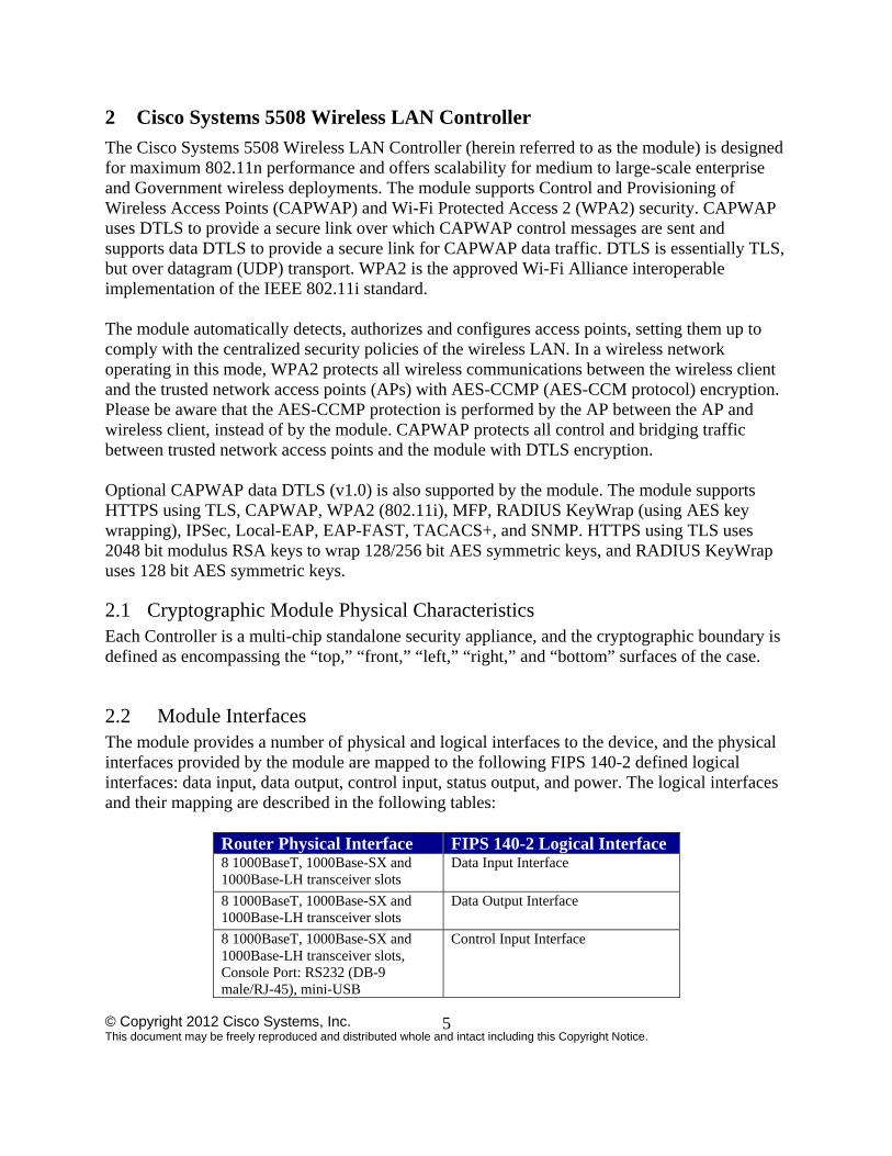
2.2 Module Interfaces The module provides a number of physical and logical interfaces to the device, and the physical interfaces provided by the module are mapped to the following FIPS 140-2 defined logical interfaces: data input, data output, control input, status output, and power. The logical interfaces and their mapping are described in the following tables:
Router Physical Interface FIPS 140-2 Logical Interface 8 1000BaseT, 1000Base-SX and 1000Base-LH transceiver slots
Data Input Interface
8 1000BaseT, 1000Base-SX and 1000Base-LH transceiver slots
Data Output Interface
8 1000BaseT, 1000Base-SX and 1000Base-LH transceiver slots, Console Port: RS232 (DB-9 male/RJ-45), mini-USB
Control Input Interface
© Copyright 2012 Cisco Systems, Inc. This document may be freely reproduced and distributed whole and intact including this Copyright Notice.
6
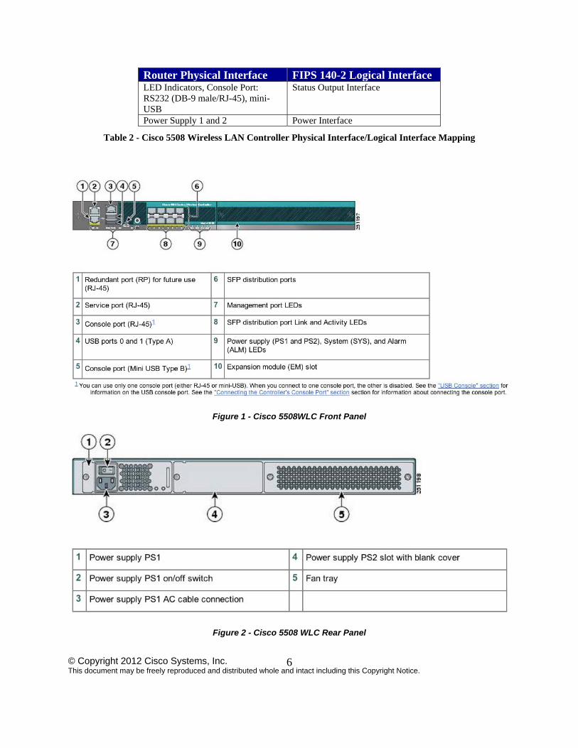
Router Physical Interface FIPS 140-2 Logical Interface LED Indicators, Console Port: RS232 (DB-9 male/RJ-45), mini-USB
Status Output Interface
Power Supply 1 and 2 Power Interface
Table 2 - Cisco 5508 Wireless LAN Controller Physical Interface/Logical Interface Mapping
Figure 1 - Cisco 5508WLC Front Panel
Figure 2 - Cisco 5508 WLC Rear Panel
© Copyright 2012 Cisco Systems, Inc. This document may be freely reproduced and distributed whole and intact including this Copyright Notice.
7
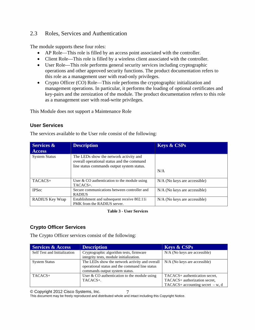
2.3 Roles, Services and Authentication The module supports these four roles:
AP Role—This role is filled by an access point associated with the controller. Client Role—This role is filled by a wireless client associated with the controller. User Role—This role performs general security services including cryptographic
operations and other approved security functions. The product documentation refers to this role as a management user with read-only privileges.
Crypto Officer (CO) Role—This role performs the cryptographic initialization and management operations. In particular, it performs the loading of optional certificates and key-pairs and the zeroization of the module. The product documentation refers to this role as a management user with read-write privileges.
This Module does not support a Maintenance Role
User Services
The services available to the User role consist of the following: Services & Access
Description Keys & CSPs
System Status The LEDs show the network activity and overall operational status and the command line status commands output system status.
N/A
TACACS+ User & CO authentication to the module using TACACS+.
N/A (No keys are accessible)
IPSec Secure communications between controller and RADIUS
N/A (No keys are accessible)
RADIUS Key Wrap Establishment and subsequent receive 802.11i PMK from the RADIUS server.
N/A (No keys are accessible)
Table 3 - User Services
Crypto Officer Services
The Crypto Officer services consist of the following: Services & Access Description Keys & CSPs Self Test and Initialization Cryptographic algorithm tests, firmware
integrity tests, module initialization. N/A (No keys are accessible)
System Status The LEDs show the network activity and overall operational status and the command line status commands output system status.
N/A (No keys are accessible)
TACACS+ User & CO authentication to the module using TACACS+.
TACACS+ authentication secret, TACACS+ authorization secret, TACACS+ accounting secret – w, d
© Copyright 2012 Cisco Systems, Inc. This document may be freely reproduced and distributed whole and intact including this Copyright Notice.
8
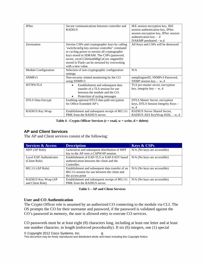
IPSec Secure communications between controller and RADIUS
IKE session encryption key, IKE session authentication key, IPSec session encryption key, IPSec session authentication key – d ISAKMP preshared – w,d
Zeroization Zeroize CSPs and cryptographic keys by calling ‘switchconfig key-zeroize controller’ command or cycling power to zeroize all cryptographic keys stored in SDRAM. The CSPs (password, secret, cscoCCDefaultMfgCaCert, engineID) stored in Flash can be zeroized by overwriting with a new value.
All Keys and CSPs will be destroyed
Module Configuration Selection of non-cryptographic configuration settings
N/A
SNMPv3 Non-security related monitoring by the CO using SNMPv3
snmpEngineID, SNMPv3 Password, SNMP session key – w, d
HTTPS/TLS Establishment and subsequent data transfer of a TLS session for use between the module and the CO.
Protection of syslog messages
TLS pre-master secret, encryption key, integrity key – w, d
DTLS Data Encrypt Enabling optional DTLS data path encryption for Office Extended AP’s
DTLS Master Secret, encryption keys, DTLS Session Integrity Keys – w, d
RADIUS Key Wrap Establishment and subsequent receipt of 802.11i PMK from the RADIUS server.
RADIUS Server Shared Secret, RADIUS AES KeyWrap KEK, – w, d
Table 4 - Crypto Officer Services (r = read, w = write, d = delete)
AP and Client Services The AP and Client services consist of the following: Services & Access Description Keys & CSPs MFP (AP Role) Generation and subsequent distribution of MFP
key to the AP over a CAPWAP session. N/A (No keys are accessible)
Local EAP Authenticator (Client Role)
Establishment of EAP-TLS or EAP-FAST based authentication between the client and the Controller.
N/A (No keys are accessible)
802.11i (AP Role) Establishment and subsequent data transfer of an 802.11i session for use between the client and the access point
N/A (No keys are accessible)
RADIUS Key Wrap (AP and Client Role)
Establishment and subsequent receipt of 802.11i PMK from the RADIUS server.
N/A (No keys are accessible)
Table 5 – AP and Client Services
User and CO Authentication The Crypto Officer role is assumed by an authorized CO connecting to the module via CLI. The OS prompts the CO for their username and password, if the password is validated against the CO’s password in memory, the user is allowed entry to execute CO services. CO passwords must be at least eight (8) characters long, including at least one letter and at least one number character, in length (enforced procedurally). If six (6) integers, one (1) special
© Copyright 2012 Cisco Systems, Inc. This document may be freely reproduced and distributed whole and intact including this Copyright Notice.
9
character and one (1) alphabet are used without repetition for an eight (8) digit PIN, the probability of randomly guessing the correct sequence is one (1) in 251,596,800 (this calculation is based on the assumption that the typical standard American QWERTY computer keyboard has 10 Integer digits, 52 alphabetic characters, and 32 special characters providing 94 characters to choose from in total. The calculation should be 10 x 9 x 8 x 7 x 6 x 5 x 32 x 52 = 251, 596, 800). Therefore, the associated probability of a successful random attempt is approximately 1 in 251,596,800, which is less than 1 in 1,000,000 required by FIPS 140-2. AP Authentication The module performs mutual authentication with an access point through the CAPWAP protocol, using an RSA key pair with 1024 to 2048 bit modulus, which has an equivalent symmetric key strength of 80 and 112 bits. Assuming the low end of that range, an attacker would have a 1 in 2^80 chance of randomly obtaining the key, which is much stronger than the one in a million chance required by FIPS 140-2. To exceed a one in 100,000 probability of a successful random key guess in one minute, an attacker would have to be capable of approximately 1.8 x 10^21 attempts per minute, which far exceeds the operational capabilities of the modules to support. Client Authentication The module performs mutual authentication with a wireless client through EAP-TLS or EAP-FAST protocols. EAP-FAST is based on EAP-TLS and uses EAP-TLS key pair and certificates. The RSA key pair for the EAP-TLS credentials has modulus size of 1024 bit to 2048 bit, thus providing between 80 bits and 112 bits of strength. Assuming the low end of that range, an attacker would have a 1 in 2^80 chance of randomly obtaining the key, which is much stronger than the one in a million chance required by FIPS 140-2. To exceed a one in 100,000 probability of a successful random key guess in one minute, an attacker would have to be capable of approximately 1.8 x 10^21 attempts per minute, which far exceeds the operational capabilities of the modules to support.
2.4 Services Available in a Non-FIPS Mode of Operation
SSHv1 SNMP v1 and v2 IPSec/IKE with Diffie-Hellman 768-bit/1024-bit modulus and Triple-DES
2.5 Unauthenticated Services An unauthenticated operator may observe the System Status by viewing the LEDs on the module, which show network activity and overall operational status. A solid green LED indicates normal operation and the successful completion of self-tests. The module does not support a bypass capability in the approved mode of operations.
© Copyright 2012 Cisco Systems, Inc. This document may be freely reproduced and distributed whole and intact including this Copyright Notice.
10
2.6 Physical Security This section describes placement of tamper-evident labels and opacity shields on the module. Labels must be placed on the device and maintained by the Crypto Officer in order to operate in the FIPS approved mode of operation. The 5508 FIPS kit (AIR-CT5508FIPSKIT=) which includes the FIPS opacity shield and FIPS Tamper Evident Labels. The Tamper Evident Labels shall be installed for the module to operate in a FIPS Approved mode of operation. Please note that the placement of tamper-evident labels on the module is not required for FIPS 140 security Level 1 deployments. For FIPS 140 security level 2 scenarios, the tamper-evident labels are required to meet physical security requirements Follow these steps to install the opacity shield and tamper evident labels:
1) Align the FIPS shield to the front of the controller unit, aligning screw holes to existing mount holes on left and right sides of controller.
2) Attach one of the front brackets to the controller using three M4 screws. The screws will go through the front mount bracket, then through the FIPS shield, and thread into the side of the controller. Follow the same steps to attach the second bracket to the opposite side. - Note that only three of the four holes on each bracket are used (top, left, and right).
3) Clean the cover of any grease, dirt, or oil before applying the tamper evidence labels. Alcohol-based cleaning pads are recommended for this purpose. The temperature of the router should be above 10C.
4) Put tamper-evident labels over the bottom panel. 5) Attach the opacity shield over the front face. 6) Place one seal each over the left and right side mounting brackets, for a total of two (2)
labels These protect the front opacity shield from removal. The two (2) seals on the rear protect any components from being removed without tamper evidence. All four seals protect against the removal or prying open of the top cover to expose the module's interior.
7) The labels completely cure within five minutes.
© Copyright 2012 Cisco Systems, Inc. This document may be freely reproduced and distributed whole and intact including this Copyright Notice.
11
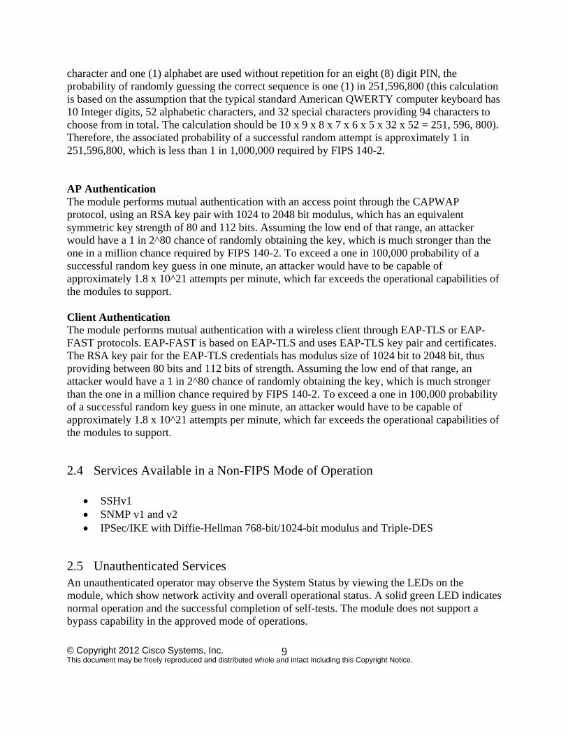
Figure 3 - Tamper Evident Label Placement (side view)
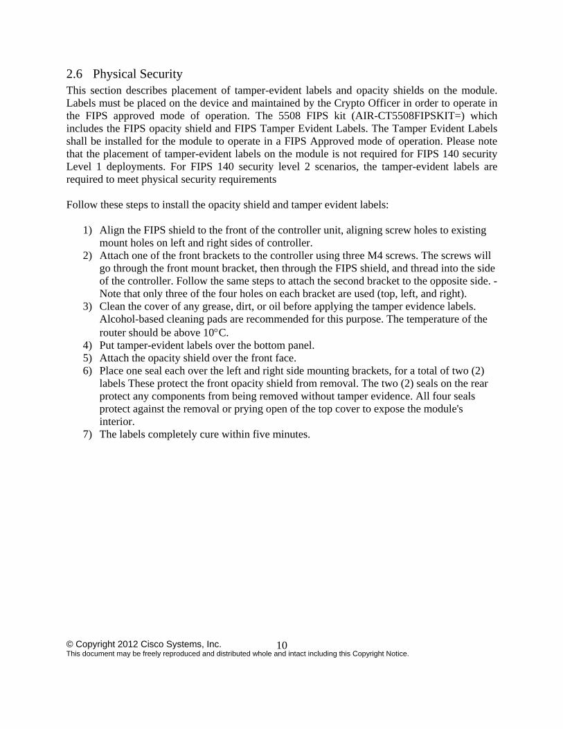
Figure 4 - Tamper Evident Label Placement (rear view)
The tamper evident seals are produced from a special thin gauge vinyl with self-adhesive backing. Any attempt to open the device will damage the tamper evident seals or the material of the security appliance cover. Because the tamper evident seals have non-repeated serial numbers, they may be inspected for damage and compared against the applied serial numbers to verify that the security appliance has not been tampered with. Tamper evident seals can also be inspected for signs of tampering, which include the following: curled corners, rips, and slices. The word “OPEN” may appear if the label was peeled back. The Crypto-Officer should inspect the seals for evidence of tamper as determined by their deployment policies (every 30 days is recommended). If the seals show evidence of tamper, the Crypto-Officer should assume that the modules have been compromised and contact Cisco accordingly NOTE: Any unused TELs must be securely stored, accounted for, and maintained by the CO in a protected location.
© Copyright 2012 Cisco Systems, Inc. This document may be freely reproduced and distributed whole and intact including this Copyright Notice.
12
2.7 Cryptographic Algorithms
The module implements a variety of approved and non-approved algorithms.
Approved Cryptographic Algorithms
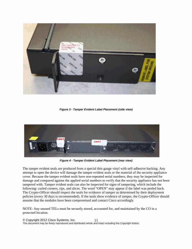
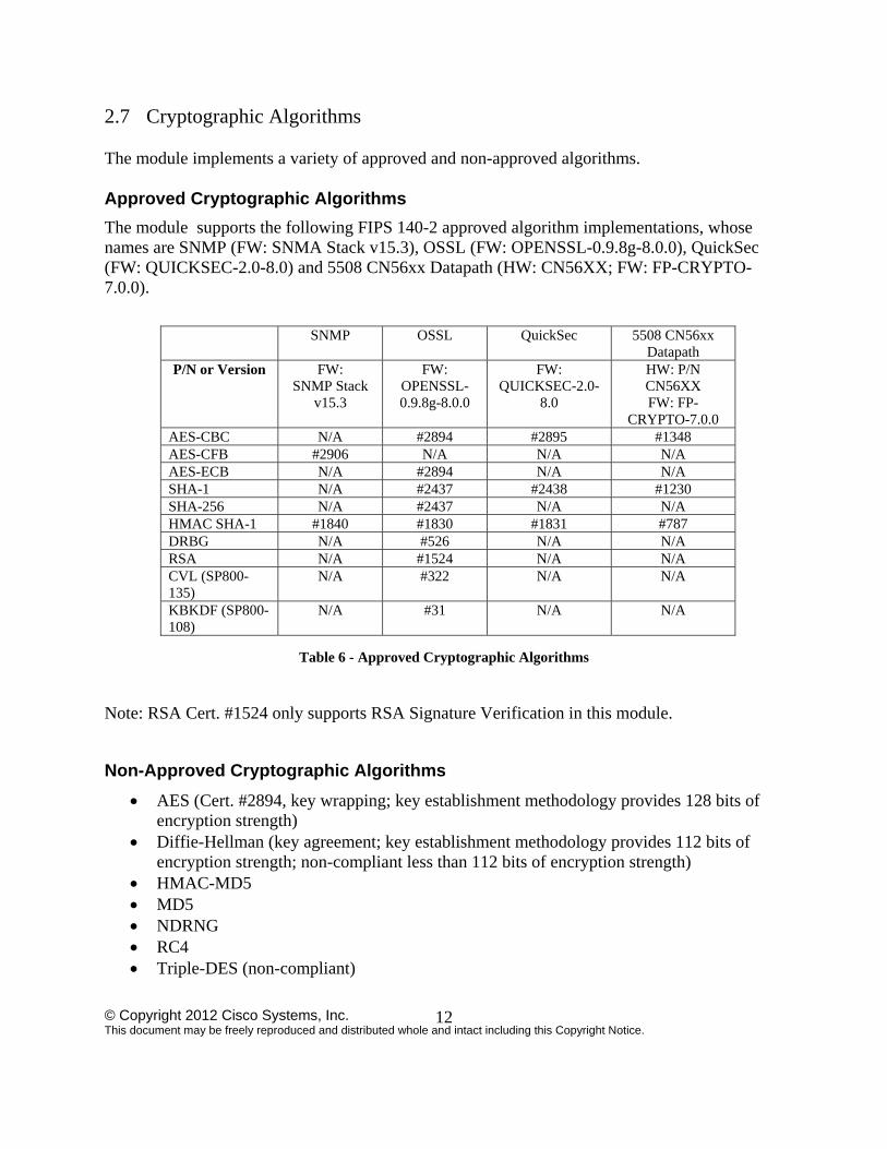
The module supports the following FIPS 140-2 approved algorithm implementations, whose names are SNMP (FW: SNMA Stack v15.3), OSSL (FW: OPENSSL-0.9.8g-8.0.0), QuickSec (FW: QUICKSEC-2.0-8.0) and 5508 CN56xx Datapath (HW: CN56XX; FW: FP-CRYPTO-7.0.0).
Table 6 - Approved Cryptographic Algorithms
Note: RSA Cert. #1524 only supports RSA Signature Verification in this module.
Non-Approved Cryptographic Algorithms
AES (Cert. #2894, key wrapping; key establishment methodology provides 128 bits of encryption strength)
Diffie-Hellman (key agreement; key establishment methodology provides 112 bits of encryption strength; non-compliant less than 112 bits of encryption strength)
HMAC-MD5 MD5 NDRNG RC4 Triple-DES (non-compliant)
SNMP OSSL QuickSec 5508 CN56xx Datapath
P/N or Version FW: SNMP Stack
v15.3
FW: OPENSSL-0.9.8g-8.0.0
FW: QUICKSEC-2.0-
8.0
HW: P/N CN56XX FW: FP-
CRYPTO-7.0.0 AES-CBC N/A #2894 #2895 #1348 AES-CFB #2906 N/A N/A N/A AES-ECB N/A #2894 N/A N/A SHA-1 N/A #2437 #2438 #1230 SHA-256 N/A #2437 N/A N/A HMAC SHA-1 #1840 #1830 #1831 #787 DRBG N/A #526 N/A N/A RSA N/A #1524 N/A N/A CVL (SP800-135)
N/A #322 N/A N/A
KBKDF (SP800-108)
N/A #31 N/A N/A
© Copyright 2012 Cisco Systems, Inc. This document may be freely reproduced and distributed whole and intact including this Copyright Notice.
13
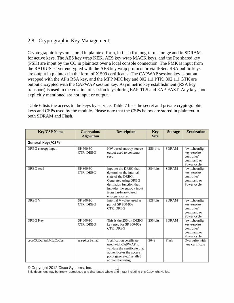
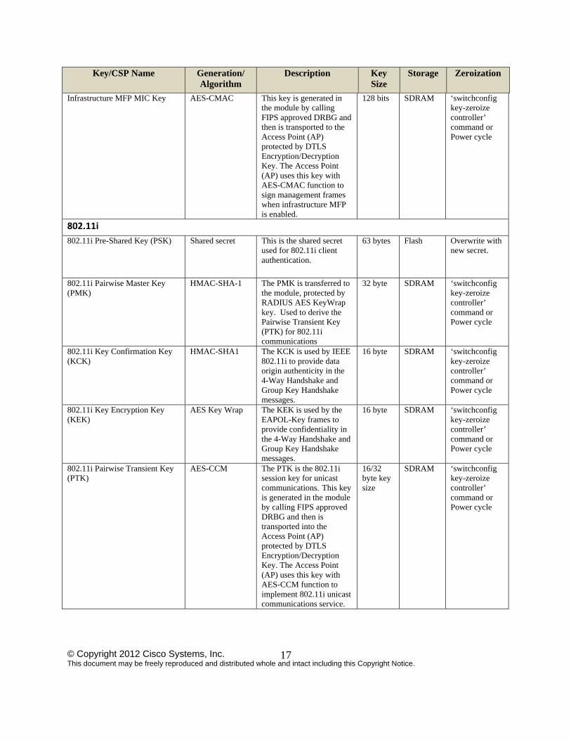
2.8 Cryptographic Key Management Cryptographic keys are stored in plaintext form, in flash for long-term storage and in SDRAM for active keys. The AES key wrap KEK, AES key wrap MACK keys, and the Pre shared key (PSK) are input by the CO in plaintext over a local console connection. The PMK is input from the RADIUS server encrypted with the AES key wrap protocol or via IPSec. RSA public keys are output in plaintext in the form of X.509 certificates. The CAPWAP session key is output wrapped with the AP's RSA key, and the MFP MIC key and 802.11i PTK, 802.11i GTK are output encrypted with the CAPWAP session key. Asymmetric key establishment (RSA key transport) is used in the creation of session keys during EAP-TLS and EAP-FAST. Any keys not explicitly mentioned are not input or output. Table 6 lists the access to the keys by service. Table 7 lists the secret and private cryptographic keys and CSPs used by the module. Please note that the CSPs below are stored in plaintext in both SDRAM and Flash.
Key/CSP Name Generation/ Algorithm
Description Key Size
Storage Zeroization
General Keys/CSPs
DRBG entropy input SP 800-90 CTR_DRBG
HW based entropy source output used to construct seed
256-bits SDRAM ‘switchconfig key-zeroize controller’ command or Power cycle
DRBG seed SP 800-90 CTR_DRBG
Input to the DRBG that determines the internal state of the DRBG. Generated using DRBG derivation function that includes the entropy input from hardware-based entropy source.
384 bits SDRAM ‘switchconfig key-zeroize controller’ command or Power cycle
DRBG V SP 800-90 CTR_DRBG
Internal V value used as part of SP 800-90a CTR_DRBG
128 bits SDRAM ‘switchconfig key-zeroize controller’ command or Power cycle
DRBG Key SP 800-90 CTR_DRBG
This is the 256-bit DRBG key used for SP 800-90a CTR_DRBG
256 bits SDRAM ‘switchconfig key-zeroize controller’ command or Power cycle
cscoCCDefaultMfgCaCert rsa-pkcs1-sha2 Verification certificate, used with CAPWAP to validate the certificate that authenticates the access point generated/installed at manufacturing
2048 Flash Overwrite with new certificate
© Copyright 2012 Cisco Systems, Inc. This document may be freely reproduced and distributed whole and intact including this Copyright Notice.
14
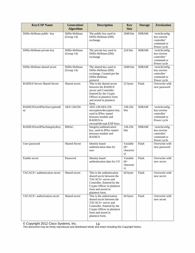
Key/CSP Name Generation/ Algorithm
Description Key Size
Storage Zeroization
Diffie-Hellman public key Diffie-Hellman (Group 14)
The public key used in Diffie-Hellman (DH) exchange
2048 bits SDRAM ‘switchconfig key-zeroize controller’ command or Power cycle
Diffie-Hellman private key Diffie-Hellman (Group 14)
The private key used in Diffie-Hellman (DH) exchange
224 bits SDRAM ‘switchconfig key-zeroize controller’ command or Power cycle
Diffie-Hellman shared secret Diffie-Hellman (Group 14)
The shared key used in Diffie-Hellman (DH) exchange. Created per the Diffie-Hellman protocol
2048 bits SDRAM ‘switchconfig key-zeroize controller’ command or Power cycle
RADIUS Server Shared Secret Shared secret This is the shared secret between the RADIUS server and Controller. Entered by the Crypto Officer in plaintext form and stored in plaintext form.
22 bytes Flash Overwrite with new password
RADIUSOverIPSecEncryptionKey
AES-128/256 AES-128/AES-256 encryption/decryption key, used in IPSec tunnel between module and RADIUS to encrypt/decrypt EAP keys.
128-256 bits
SDRAM ‘switchconfig key-zeroize controller’ command or Power cycle
RADIUSOverIPSecIntegrityKey HMAC Integrity/authentication key, used in IPSec tunnel between module and RADIUS
128-256 bits
SDRAM ‘switchconfig key-zeroize controller’ command or Power cycle
User password Shared Secret Identity based authentication data for user
Variable (8+ characters)
Flash Overwrite with new password
Enable secret Password Identity based authentication data for CO
Variable (8+ characters)
Flash Overwrite with new secret
TACACS+ authentication secret Shared secret This is the authentication shared secret between the TACACS+ server and Controller. Entered by the Crypto Officer in plaintext form and stored in plaintext form.
64 bytes Flash Overwrite with new secret
TACACS+ authorization secret Shared secret This is the authorization shared secret between the TACACS+ server and Controller. Entered by the Crypto Officer in plaintext form and stored in plaintext form.
64 bytes Flash Overwrite with new secret
© Copyright 2012 Cisco Systems, Inc. This document may be freely reproduced and distributed whole and intact including this Copyright Notice.
15
Key/CSP Name Generation/ Algorithm
Description Key Size
Storage Zeroization
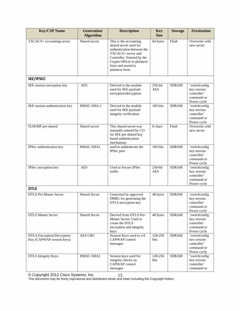
TACACS+ accounting secret Shared secret This is the accounting shared secret used for authentication between the TACACS+ server and Controller. Entered by the Crypto Officer in plaintext form and stored in plaintext form.
64 bytes Flash Overwrite with new secret
IKE/IPSEC
IKE session encryption key AES Derived in the module used for IKE payload encryption/decryption
256-bit AES
SDRAM ‘switchconfig key-zeroize controller’ command or Power cycle
IKE session authentication key HMAC-SHA-1 Derived in the module used for IKE payload integrity verification
160 bits SDRAM ‘switchconfig key-zeroize controller’ command or Power cycle
ISAKMP pre-shared Shared secret This shared secret was manually entered by CO for IKE pre-shared key based authentication mechanism.
8 chars Flash Overwrite with new secret
IPSec authentication key HMAC-SHA1 used to authenticate the IPSec peer
160 bits SDRAM ‘switchconfig key-zeroize controller’ command or Power cycle
IPSec encryption key AES Used to Secure IPSec traffic
256-bit AES
SDRAM ‘switchconfig key-zeroize controller’ command or Power cycle
DTLS
DTLS Pre-Master Secret Shared Secret Generated by approved DRBG for generating the DTLS encryption key
48 bytes SDRAM ‘switchconfig key-zeroize controller’ command or Power cycle
DTLS Master Secret Shared Secret Derived from DTLS Pre-Master Secret. Used to create the DTLS encryption and integrity keys
48 bytes SDRAM ‘switchconfig key-zeroize controller’ command or Power cycle
DTLS Encryption/Decryption Key (CAPWAP session keys)
AES-CBC Session Keys used to e/d CAPWAP control messages
128-256 bits
SDRAM
‘switchconfig key-zeroize controller’ command or Power cycle
DTLS Integrity Keys HMAC-SHA1 Session keys used for integrity checks on CAPWAP control messages
128-256 bits
SDRAM ‘switchconfig key-zeroize controller’ command or
© Copyright 2012 Cisco Systems, Inc. This document may be freely reproduced and distributed whole and intact including this Copyright Notice.
16
Key/CSP Name Generation/ Algorithm
Description Key Size
Storage Zeroization
Power cycle
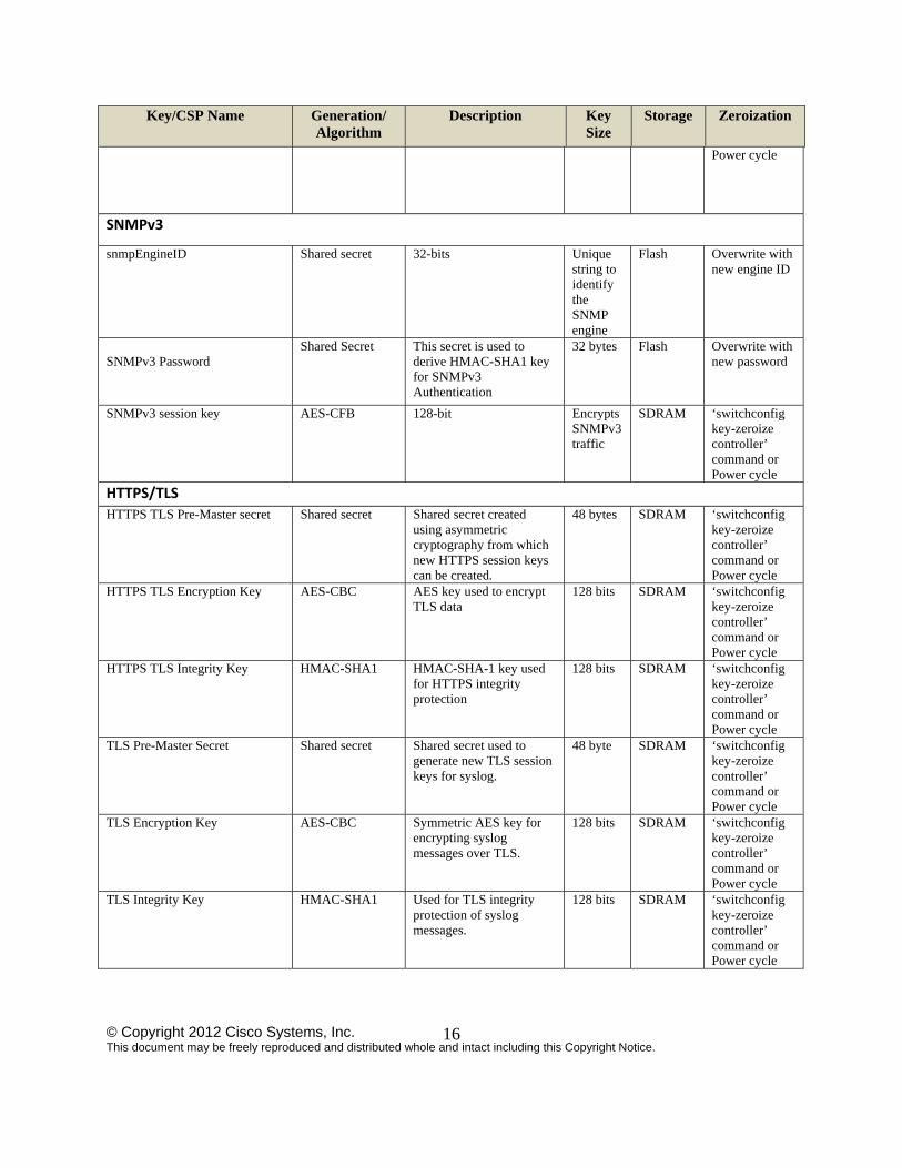
SNMPv3
snmpEngineID Shared secret 32-bits Unique string to identify the SNMP engine
Flash Overwrite with new engine ID
SNMPv3 Password
Shared Secret This secret is used to derive HMAC-SHA1 key for SNMPv3 Authentication
32 bytes Flash Overwrite with new password
SNMPv3 session key AES-CFB 128-bit Encrypts SNMPv3 traffic
SDRAM ‘switchconfig key-zeroize controller’ command or Power cycle
HTTPS/TLS
HTTPS TLS Pre-Master secret Shared secret Shared secret created using asymmetric cryptography from which new HTTPS session keys can be created.
48 bytes SDRAM ‘switchconfig key-zeroize controller’ command or Power cycle
HTTPS TLS Encryption Key AES-CBC AES key used to encrypt TLS data
128 bits SDRAM ‘switchconfig key-zeroize controller’ command or Power cycle
HTTPS TLS Integrity Key HMAC-SHA1 HMAC-SHA-1 key used for HTTPS integrity protection
128 bits SDRAM ‘switchconfig key-zeroize controller’ command or Power cycle
TLS Pre-Master Secret Shared secret Shared secret used to generate new TLS session keys for syslog.
48 byte SDRAM ‘switchconfig key-zeroize controller’ command or Power cycle
TLS Encryption Key AES-CBC Symmetric AES key for encrypting syslog messages over TLS.
128 bits SDRAM ‘switchconfig key-zeroize controller’ command or Power cycle
TLS Integrity Key HMAC-SHA1 Used for TLS integrity protection of syslog messages.
128 bits SDRAM ‘switchconfig key-zeroize controller’ command or Power cycle
© Copyright 2012 Cisco Systems, Inc. This document may be freely reproduced and distributed whole and intact including this Copyright Notice.
17
Key/CSP Name Generation/ Algorithm
Description Key Size
Storage Zeroization
Infrastructure MFP MIC Key AES-CMAC This key is generated in the module by calling FIPS approved DRBG and then is transported to the Access Point (AP) protected by DTLS Encryption/Decryption Key. The Access Point (AP) uses this key with AES-CMAC function to sign management frames when infrastructure MFP is enabled.
128 bits SDRAM ‘switchconfig key-zeroize controller’ command or Power cycle
802.11i
802.11i Pre-Shared Key (PSK) Shared secret This is the shared secret used for 802.11i client authentication.
63 bytes Flash Overwrite with new secret.
802.11i Pairwise Master Key (PMK)
HMAC-SHA-1
The PMK is transferred to the module, protected by RADIUS AES KeyWrap key. Used to derive the Pairwise Transient Key (PTK) for 802.11i communications
32 byte SDRAM ‘switchconfig key-zeroize controller’ command or Power cycle
802.11i Key Confirmation Key (KCK)
HMAC-SHA1 The KCK is used by IEEE 802.11i to provide data origin authenticity in the 4-Way Handshake and Group Key Handshake messages.
16 byte SDRAM ‘switchconfig key-zeroize controller’ command or Power cycle
802.11i Key Encryption Key (KEK)
AES Key Wrap The KEK is used by the EAPOL-Key frames to provide confidentiality in the 4-Way Handshake and Group Key Handshake messages.
16 byte SDRAM ‘switchconfig key-zeroize controller’ command or Power cycle
802.11i Pairwise Transient Key (PTK)
AES-CCM The PTK is the 802.11i session key for unicast communications. This key is generated in the module by calling FIPS approved DRBG and then is transported into the Access Point (AP) protected by DTLS Encryption/Decryption Key. The Access Point (AP) uses this key with AES-CCM function to implement 802.11i unicast communications service.
16/32 byte key size
SDRAM ‘switchconfig key-zeroize controller’ command or Power cycle
© Copyright 2012 Cisco Systems, Inc. This document may be freely reproduced and distributed whole and intact including this Copyright Notice.
18
Key/CSP Name Generation/ Algorithm
Description Key Size
Storage Zeroization
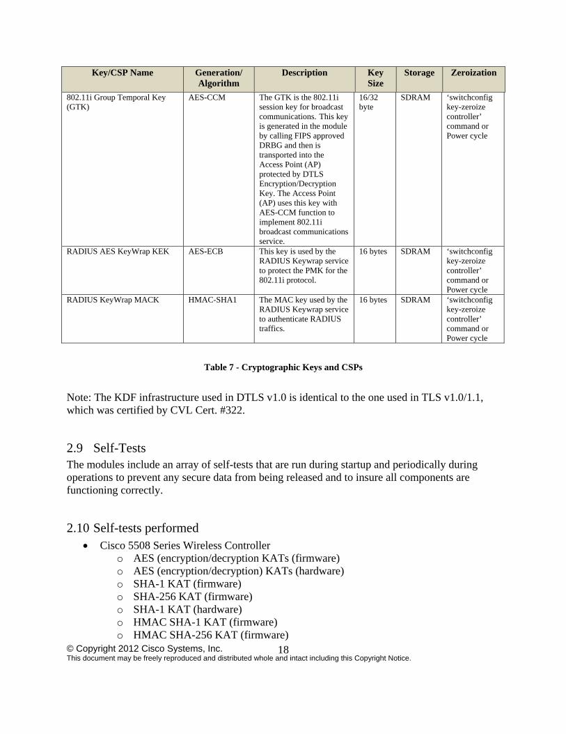
802.11i Group Temporal Key (GTK)
AES-CCM The GTK is the 802.11i session key for broadcast communications. This key is generated in the module by calling FIPS approved DRBG and then is transported into the Access Point (AP) protected by DTLS Encryption/Decryption Key. The Access Point (AP) uses this key with AES-CCM function to implement 802.11i broadcast communications service.
16/32 byte
SDRAM ‘switchconfig key-zeroize controller’ command or Power cycle
RADIUS AES KeyWrap KEK AES-ECB This key is used by the RADIUS Keywrap service to protect the PMK for the 802.11i protocol.
16 bytes SDRAM ‘switchconfig key-zeroize controller’ command or Power cycle
RADIUS KeyWrap MACK HMAC-SHA1 The MAC key used by the RADIUS Keywrap service to authenticate RADIUS traffics.
16 bytes SDRAM ‘switchconfig key-zeroize controller’ command or Power cycle
Table 7 - Cryptographic Keys and CSPs
Note: The KDF infrastructure used in DTLS v1.0 is identical to the one used in TLS v1.0/1.1, which was certified by CVL Cert. #322.
2.9 Self-Tests The modules include an array of self-tests that are run during startup and periodically during operations to prevent any secure data from being released and to insure all components are functioning correctly.
2.10 Self-tests performed Cisco 5508 Series Wireless Controller
o AES (encryption/decryption KATs (firmware) o AES (encryption/decryption) KATs (hardware) o SHA-1 KAT (firmware) o SHA-256 KAT (firmware) o SHA-1 KAT (hardware) o HMAC SHA-1 KAT (firmware) o HMAC SHA-256 KAT (firmware)
© Copyright 2012 Cisco Systems, Inc. This document may be freely reproduced and distributed whole and intact including this Copyright Notice.
19
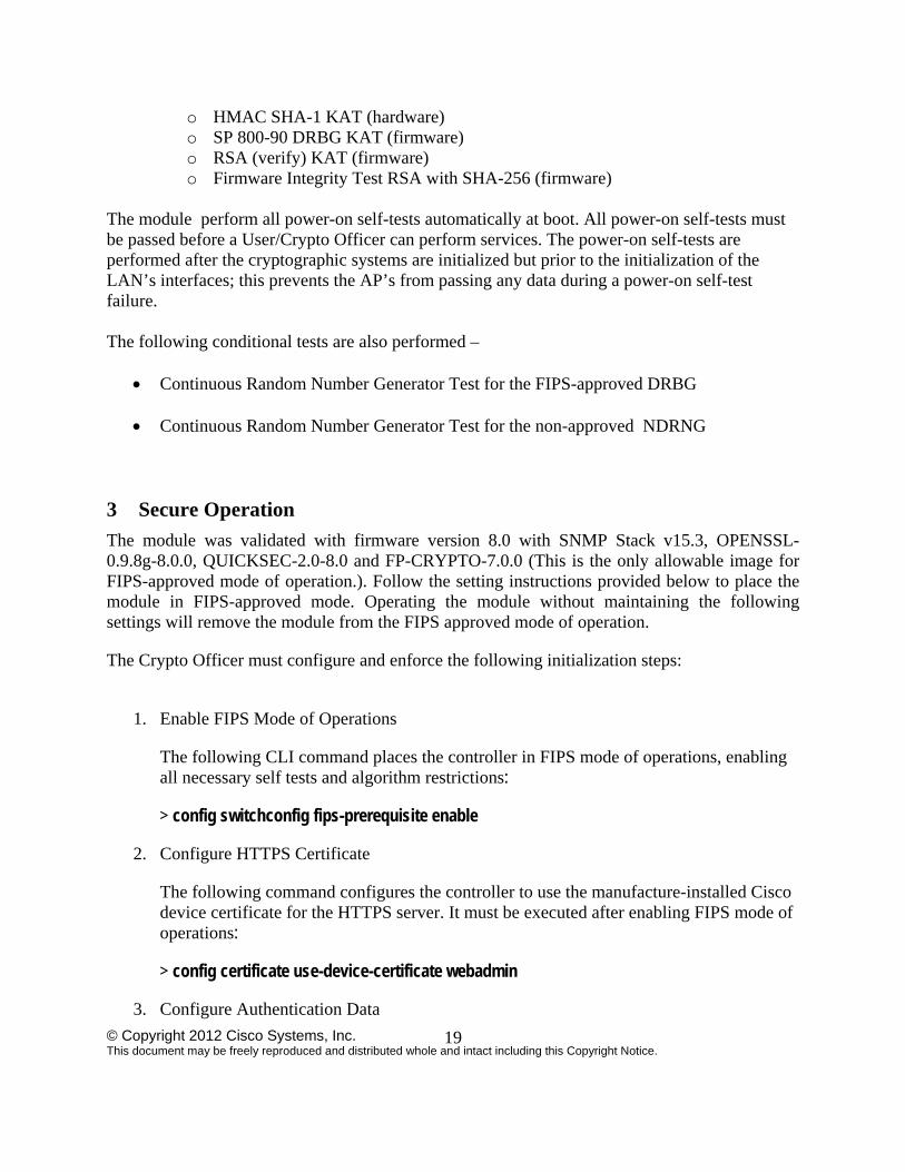
o HMAC SHA-1 KAT (hardware) o SP 800-90 DRBG KAT (firmware) o RSA (verify) KAT (firmware) o Firmware Integrity Test RSA with SHA-256 (firmware)
The module perform all power-on self-tests automatically at boot. All power-on self-tests must be passed before a User/Crypto Officer can perform services. The power-on self-tests are performed after the cryptographic systems are initialized but prior to the initialization of the LAN’s interfaces; this prevents the AP’s from passing any data during a power-on self-test failure. The following conditional tests are also performed –
Continuous Random Number Generator Test for the FIPS-approved DRBG
Continuous Random Number Generator Test for the non-approved NDRNG 3 Secure Operation
The module was validated with firmware version 8.0 with SNMP Stack v15.3, OPENSSL-0.9.8g-8.0.0, QUICKSEC-2.0-8.0 and FP-CRYPTO-7.0.0 (This is the only allowable image for FIPS-approved mode of operation.). Follow the setting instructions provided below to place the module in FIPS-approved mode. Operating the module without maintaining the following settings will remove the module from the FIPS approved mode of operation.
The Crypto Officer must configure and enforce the following initialization steps:
1. Enable FIPS Mode of Operations
The following CLI command places the controller in FIPS mode of operations, enabling all necessary self tests and algorithm restrictions:
> config switchconfig fips-prerequisite enable
2. Configure HTTPS Certificate
The following command configures the controller to use the manufacture-installed Cisco device certificate for the HTTPS server. It must be executed after enabling FIPS mode of operations:
> config certificate use-device-certificate webadmin
3. Configure Authentication Data
© Copyright 2012 Cisco Systems, Inc. This document may be freely reproduced and distributed whole and intact including this Copyright Notice.
20
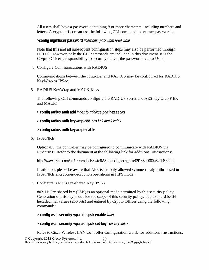
All users shall have a password containing 8 or more characters, including numbers and letters. A crypto officer can use the following CLI command to set user passwords:
>config mgmtuser password username password read-write
Note that this and all subsequent configuration steps may also be performed through HTTPS. However, only the CLI commands are included in this document. It is the Crypto Officer’s responsibility to securely deliver the password over to User.
4. Configure Communications with RADIUS
Communications between the controller and RADIUS may be configured for RADIUS KeyWrap or IPSec.
5. RADIUS KeyWrap and MACK Keys
The following CLI commands configure the RADIUS secret and AES-key wrap KEK and MACK:
> config radius auth add index ip-address port hex secret
> config radius auth keywrap add hex kek mack index
> config radius auth keywrap enable
6. IPSec/IKE
Optionally, the controller may be configured to communicate with RADIUS via IPSec/IKE. Refer to the document at the following link for additional instructions:
http://www.cisco.com/en/US/products/ps6366/products_tech_note09186a0080a829b8.shtml
In addition, please be aware that AES is the only allowed symmetric algorithm used in IPSec/IKE encryption/decryption operations in FIPS mode.
7. Configure 802.11i Pre-shared Key (PSK)
802.11i Pre-shared key (PSK) is an optional mode permitted by this security policy. Generation of this key is outside the scope of this security policy, but it should be 64 hexadecimal values (256 bits) and entered by Crypto Officer using the following commands:
> config wlan security wpa akm psk enable index
> config wlan security wpa akm psk set-key hex key index
Refer to Cisco Wireless LAN Controller Configuration Guide for additional instructions.
© Copyright 2012 Cisco Systems, Inc. This document may be freely reproduced and distributed whole and intact including this Copyright Notice.
21
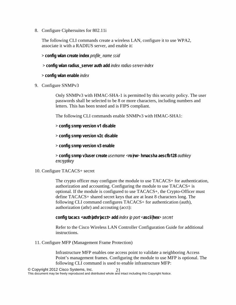
8. Configure Ciphersuites for 802.11i
The following CLI commands create a wireless LAN, configure it to use WPA2, associate it with a RADIUS server, and enable it:
> config wlan create index profile_name ssid
> config wlan radius_server auth add index radius-server-index
> config wlan enable index
9. Configure SNMPv3
Only SNMPv3 with HMAC-SHA-1 is permitted by this security policy. The user passwords shall be selected to be 8 or more characters, including numbers and letters. This has been tested and is FIPS compliant.
The following CLI commands enable SNMPv3 with HMAC-SHA1:
> config snmp version v1 disable
> config snmp version v2c disable
> config snmp version v3 enable
> config snmp v3user create username <ro|rw> hmacsha aescfb128 authkey encryptkey
10. Configure TACACS+ secret
The crypto officer may configure the module to use TACACS+ for authentication, authorization and accounting. Configuring the module to use TACACS+ is optional. If the module is configured to use TACACS+, the Crypto-Officer must define TACACS+ shared secret keys that are at least 8 characters long. The following CLI command configures TACACS+ for authentication (auth), authorization (athr) and accouting (acct):
config tacacs <auth|athr|acct> add index ip port <ascii|hex> secret
Refer to the Cisco Wireless LAN Controller Configuration Guide for additional instructions.
11. Configure MFP (Management Frame Protection)
Infrastructure MFP enables one access point to validate a neighboring Access Point’s management frames. Configuring the module to use MFP is optional. The following CLI command is used to enable infrastructure MFP:
© Copyright 2012 Cisco Systems, Inc. This document may be freely reproduced and distributed whole and intact including this Copyright Notice.
22
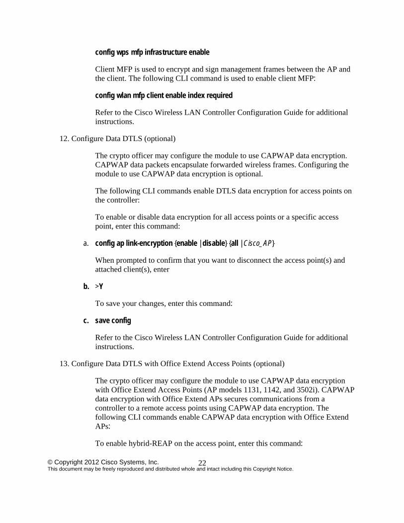
config wps mfp infrastructure enable
Client MFP is used to encrypt and sign management frames between the AP and the client. The following CLI command is used to enable client MFP:
config wlan mfp client enable index required
Refer to the Cisco Wireless LAN Controller Configuration Guide for additional instructions.
12. Configure Data DTLS (optional)
The crypto officer may configure the module to use CAPWAP data encryption. CAPWAP data packets encapsulate forwarded wireless frames. Configuring the module to use CAPWAP data encryption is optional.
The following CLI commands enable DTLS data encryption for access points on the controller:
To enable or disable data encryption for all access points or a specific access point, enter this command:
a. config ap link-encryption {enable | disable} {all | Cisco_AP}
When prompted to confirm that you want to disconnect the access point(s) and attached client(s), enter
b. >Y
To save your changes, enter this command:
c. save config
Refer to the Cisco Wireless LAN Controller Configuration Guide for additional instructions.
13. Configure Data DTLS with Office Extend Access Points (optional)
The crypto officer may configure the module to use CAPWAP data encryption with Office Extend Access Points (AP models 1131, 1142, and 3502i). CAPWAP data encryption with Office Extend APs secures communications from a controller to a remote access points using CAPWAP data encryption. The following CLI commands enable CAPWAP data encryption with Office Extend APs:
To enable hybrid-REAP on the access point, enter this command:
© Copyright 2012 Cisco Systems, Inc. This document may be freely reproduced and distributed whole and intact including this Copyright Notice.
23
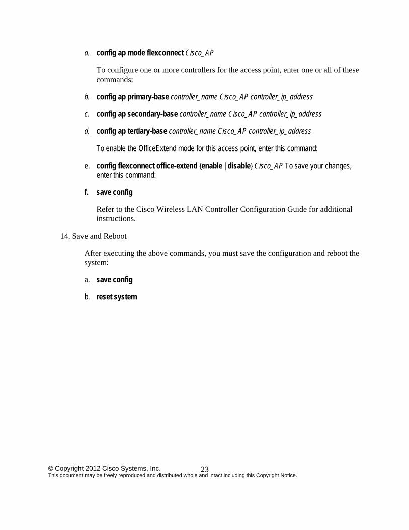
a. config ap mode flexconnect Cisco_AP
To configure one or more controllers for the access point, enter one or all of these commands:
b. config ap primary-base controller_name Cisco_AP controller_ip_address
c. config ap secondary-base controller_name Cisco_AP controller_ip_address
d. config ap tertiary-base controller_name Cisco_AP controller_ip_address
To enable the OfficeExtend mode for this access point, enter this command:
e. config flexconnect office-extend {enable | disable} Cisco_AP To save your changes, enter this command:
f. save config
Refer to the Cisco Wireless LAN Controller Configuration Guide for additional instructions.
14. Save and Reboot
After executing the above commands, you must save the configuration and reboot the system:
a. save config
b. reset system