cisco sba borderless networks—mpls wan deployment guide
TRANSCRIPT
February 2013 Series
MPLS WAN Deployment Guide
Preface
Who Should Read This GuideThis Cisco® Smart Business Architecture (SBA) guide is for people who fill a variety of roles:
• Systems engineers who need standard procedures for implementing solutions
• Project managers who create statements of work for Cisco SBA implementations
• Sales partners who sell new technology or who create implementation documentation
• Trainers who need material for classroom instruction or on-the-job training
In general, you can also use Cisco SBA guides to improve consistency among engineers and deployments, as well as to improve scoping and costing of deployment jobs.
Release SeriesCisco strives to update and enhance SBA guides on a regular basis. As we develop a series of SBA guides, we test them together, as a complete system. To ensure the mutual compatibility of designs in Cisco SBA guides, you should use guides that belong to the same series.
The Release Notes for a series provides a summary of additions and changes made in the series.
All Cisco SBA guides include the series name on the cover and at the bottom left of each page. We name the series for the month and year that we release them, as follows:
month year Series
For example, the series of guides that we released in February 2013 is the “February Series”.
You can find the most recent series of SBA guides at the following sites:
Customer access: http://www.cisco.com/go/sba
Partner access: http://www.cisco.com/go/sbachannel
How to Read CommandsMany Cisco SBA guides provide specific details about how to configure Cisco network devices that run Cisco IOS, Cisco NX-OS, or other operating systems that you configure at a command-line interface (CLI). This section describes the conventions used to specify commands that you must enter.
Commands to enter at a CLI appear as follows:
configure terminal
Commands that specify a value for a variable appear as follows:
ntp server 10.10.48.17
Commands with variables that you must define appear as follows:
class-map [highest class name]
Commands shown in an interactive example, such as a script or when the command prompt is included, appear as follows:
Router# enable
Long commands that line wrap are underlined. Enter them as one command:
wrr-queue random-detect max-threshold 1 100 100 100 100 100 100 100 100
Noteworthy parts of system output or device configuration files appear highlighted, as follows:
interface Vlan64 ip address 10.5.204.5 255.255.255.0
Comments and QuestionsIf you would like to comment on a guide or ask questions, please use the SBA feedback form.
If you would like to be notified when new comments are posted, an RSS feed is available from the SBA customer and partner pages.
PrefaceFebruary 2013 Series
Table of ContentsFebruary 2013 Series
What’s In This SBA Guide . . . . . . . . . . . . . . . . . . . . . . . . . . . . . . . . . . . . . . . . . . . . . . . . . .1
Cisco SBA Borderless Networks . . . . . . . . . . . . . . . . . . . . . . . . . . . . . . . . . . . . . . . . 1
Route to Success . . . . . . . . . . . . . . . . . . . . . . . . . . . . . . . . . . . . . . . . . . . . . . . . . . . . . . . 1
About This Guide . . . . . . . . . . . . . . . . . . . . . . . . . . . . . . . . . . . . . . . . . . . . . . . . . . . . . . . 1
Introduction . . . . . . . . . . . . . . . . . . . . . . . . . . . . . . . . . . . . . . . . . . . . . . . . . . . . . . . . . . . . . . . .2
Related Reading . . . . . . . . . . . . . . . . . . . . . . . . . . . . . . . . . . . . . . . . . . . . . . . . . . . . . . . . 2
Design Goals . . . . . . . . . . . . . . . . . . . . . . . . . . . . . . . . . . . . . . . . . . . . . . . . . . . . . . . . . . . 2
Architecture Overview . . . . . . . . . . . . . . . . . . . . . . . . . . . . . . . . . . . . . . . . . . . . . . . . . . . . .5
WAN Design . . . . . . . . . . . . . . . . . . . . . . . . . . . . . . . . . . . . . . . . . . . . . . . . . . . . . . . . . . . . 5
Quality of Service . . . . . . . . . . . . . . . . . . . . . . . . . . . . . . . . . . . . . . . . . . . . . . . . . . . . . . 12
Deploying the WAN . . . . . . . . . . . . . . . . . . . . . . . . . . . . . . . . . . . . . . . . . . . . . . . . . . . . . . .13
Overall WAN Architecture Design Goals . . . . . . . . . . . . . . . . . . . . . . . . . . . . . . . 13
Deploying an MPLS WAN . . . . . . . . . . . . . . . . . . . . . . . . . . . . . . . . . . . . . . . . . . . . . . . . .15
Business Overview . . . . . . . . . . . . . . . . . . . . . . . . . . . . . . . . . . . . . . . . . . . . . . . . . . . . . 15
Technology Overview . . . . . . . . . . . . . . . . . . . . . . . . . . . . . . . . . . . . . . . . . . . . . . . . . . 15
Deployment Details . . . . . . . . . . . . . . . . . . . . . . . . . . . . . . . . . . . . . . . . . . . . . . . . . . . 19
MPLS CE Router Configuration . . . . . . . . . . . . . . . . . . . . . . . . . . . . . . . . . . . . . 19
Remote-Site MPLS CE Router Configuration . . . . . . . . . . . . . . . . . . . . . . . 27
Adding Secondary MPLS Link on Existing MPLS CE Router . . . . . . . . 42
Remote-Site Router Configuration (Dual-Router - Router 2) . . . . . . . . 45
Deploying a WAN Remote-Site Distribution Layer . . . . . . . . . . . . . . . . . . . . . . . 56
Remote-Site Router to Distribution Layer . . . . . . . . . . . . . . . . . . . . . . . . . . . 56
Remote-Site Router to Distribution Layer (Router 2) . . . . . . . . . . . . . . . 60
Deploying WAN Quality of Service . . . . . . . . . . . . . . . . . . . . . . . . . . . . . . . . . . . . . . 64
Configuring QoS . . . . . . . . . . . . . . . . . . . . . . . . . . . . . . . . . . . . . . . . . . . . . . . . . . . 64
Appendix A: Product List . . . . . . . . . . . . . . . . . . . . . . . . . . . . . . . . . . . . . . . . . . . . . . . . 68
Appendix B: Changes . . . . . . . . . . . . . . . . . . . . . . . . . . . . . . . . . . . . . . . . . . . . . . . . . . . .71
Table of Contents
About This GuideThis deployment guide contains one or more deployment chapters, which each include the following sections:
• BusinessOverview—Describes the business use case for the design. Business decision makers may find this section especially useful.
• TechnologyOverview—Describes the technical design for the business use case, including an introduction to the Cisco products that make up the design. Technical decision makers can use this section to understand how the design works.
• DeploymentDetails—Provides step-by-step instructions for deploying and configuring the design. Systems engineers can use this section to get the design up and running quickly and reliably.
You can find the most recent series of Cisco SBA guides at the following sites:
Customer access: http://www.cisco.com/go/sba
Partner access: http://www.cisco.com/go/sbachannel
What’s In This SBA Guide
Cisco SBA Borderless NetworksCisco SBA helps you design and quickly deploy a full-service business network. A Cisco SBA deployment is prescriptive, out-of-the-box, scalable, and flexible.
Cisco SBA incorporates LAN, WAN, wireless, security, data center, application optimization, and unified communication technologies—tested together as a complete system. This component-level approach simplifies system integration of multiple technologies, allowing you to select solutions that solve your organization’s problems—without worrying about the technical complexity.
Cisco SBA Borderless Networks is a comprehensive network design targeted at organizations with up to 10,000 connected users. The SBA Borderless Network architecture incorporates wired and wireless local area network (LAN) access, wide-area network (WAN) connectivity, WAN application optimization, and Internet edge security infrastructure.
Route to SuccessTo ensure your success when implementing the designs in this guide, you should first read any guides that this guide depends upon—shown to the left of this guide on the route below. As you read this guide, specific prerequisites are cited where they are applicable.
1What’s In This SBA GuideFebruary 2013 Series
WAN Design Overview MPLS WAN Deployment Guide Additional Deployment Guides
LAN Deployment Guide
BORDERLESS NETWORKS
You Are Here Dependent GuidesPrerequisite Guides
22IntroductionFebruary 2013 Series
Introduction
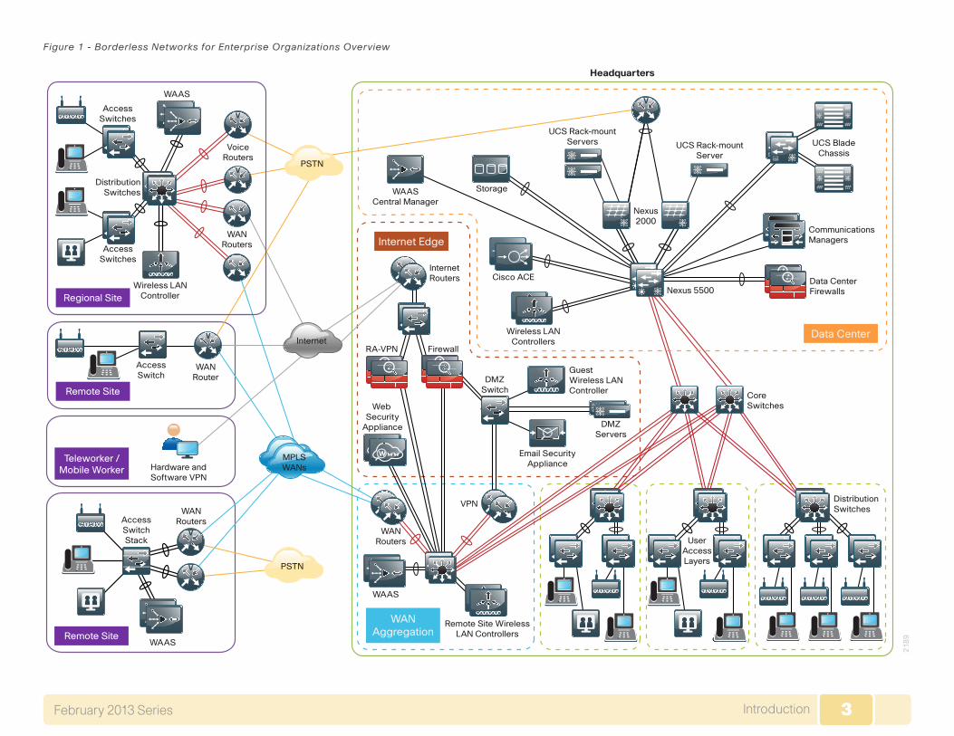
Cisco SBA—Borderless Networks is a solid network foundation designed to provide networks with up to 10,000 connected users the flexibility to sup-port new users or network services without re-engineering the network. We created a prescriptive, out-of-the-box deployment guide that is based on best-practice design principles and that delivers flexibility and scalability.
The overall WAN architecture is described in the WAN Design Overview.
To help focus on specific elements of the architecture, there are three WAN deployment guides:
• This MPLS WAN Deployment Guide provides flexible guidance and configuration for Multiprotocol Label Switching (MPLS) transport.
• Layer 2 WAN Deployment Guide provides guidance and configuration for a VPLS or Metro Ethernet transport.
• VPN WAN Deployment Guide provides guidance and configuration for broadband or Internet transport in a both a primary or backup role.
Each of these WAN deployment guides has a complementary WAN configu-ration guide.
Related ReadingThe LAN Deployment Guide describes wired network access with ubiqui-tous capabilities for both the larger campus-size LAN as well as the smaller remote-site LAN. Resiliency, security, and scalability are included to provide a robust communications environment. Quality of service (QoS) is integrated to ensure that the base architecture can support a multitude of applications, including low-latency, drop-sensitive multimedia applications coexisting with data applications on a single network.
Design Goals This architecture is based on requirements gathered from customers, partners, and Cisco field personnel for organizations with up to 10,000 con-nected users. When designing the architecture, we considered the gathered requirements and the following design goals.
3IntroductionFebruary 2013 Series 3
Figure 1 - Borderless Networks for Enterprise Organizations Overview
AccessSwitches
WAAS
DistributionSwitches
AccessSwitches
WANRouters
WANRouters
Web Security
Appliance
RA-VPN Firewall
DMZServers
WAAS
Remote Site WirelessLAN Controllers
VPN
VoiceRouters
Wireless LANController
AccessSwitchStack
WANRouters
Hardware andSoftware VPN
WANRouter
Wireless LANControllers
Cisco ACE
WAASCentral Manager
Nexus2000
Nexus 5500
CommunicationsManagers
InternetRouters
Email SecurityAppliance
DMZSwitch
GuestWireless LANController
CoreSwitches
DistributionSwitches
UserAccessLayers
Data CenterFirewalls
Storage
UCS Rack-mountServers UCS Rack-mount
Server
UCS BladeChassis
Data Center
Internet Edge
WANAggregation
MPLSWANs
Teleworker /Mobile Worker
Remote Site
Regional Site
21
89
V
AccessSwitch
Remote Site
V
V
V
wwWwwW
PSTN
Headquarters
PSTNV
V
WAAS
Internet
4IntroductionFebruary 2013 Series 4
Ease of Deployment, Flexibility, and Scalability
Organizations with up to 10,000 users are often spread out among dif-ferent geographical locations, making flexibility and scalability a critical requirement of the network. This design uses several methods to create and maintain a scalable network:
• By keeping a small number of standard designs for common portions of the network, support staff is able to design services for, implement, and support the network more effectively.
• Our modular design approach enhances scalability. Beginning with a set of standard, global building blocks, we can assemble a scalable network to meet requirements.
• Many of the plug-in modules look identical for several service areas; this common look provides consistency and scalability in that the same support methods can be used to maintain multiple areas of the network. These modules follow standard core-distribution-access network design models and use layer separation to ensure that interfaces between the plug-ins are well defined.
Resiliency and Security
One of the keys to maintaining a highly available network is building appro-priate redundancy to guard against failure in the network. The redundancy in our architecture is carefully balanced with the complexity inherent in redundant systems.
With the addition of a significant amount of delay-sensitive and drop-sensitive traffic such as voice and video conferencing, we also place a strong emphasis on recovery times. Choosing designs that reduce the time between failure detection and recovery is important for ensuring that the network stays available even in the face of a minor component failure.
Network security is also a strong component of the architecture. In a large network, there are many entry points and we ensure that they are as secure as possible without making the network too difficult to use. Securing the network not only helps keep the network safe from attacks but is also a key component to network-wide resiliency.
Ease of Management
While this guide focuses on the deployment of the network foundation, the design takes next phase management and operation into consideration. The configurations in the deployment guides are designed to allow the devices to be managed via normal device management connections, such as SSH and HTTPS, as well as via NMS. The configuration of the NMS is not covered in this guide.
Advanced Technology–Ready
Flexibility, scalability, resiliency, and security all are characteristics of an advanced technology-ready network. The modular design of the architec-ture means that technologies can be added when the organization is ready to deploy them. However, the deployment of advanced technologies, such as collaboration, is eased because the architecture includes products and configurations that are ready to support collaboration from day one. For example:
• Access switches provide Power over Ethernet (PoE) for phone deploy-ments without the need for a local power outlet.
• The entire network is preconfigured with QoS to support high-quality voice, video, and collaboration applications.
• Multicast is configured in the network to support efficient voice and broadcast-video delivery.
• The wireless network is preconfigured for devices that send voice over the wireless LAN, providing IP telephony over 802.11 Wi-Fi (referred to as mobility) at all locations.
• Video and voice perform better through the use of medianet technolo-gies, Cisco’s recommended approach for video and collaboration, which simplifies, lowers the risks, cuts costs, and improves the quality of your video and voice deployments.
The Internet Edge is ready to provide soft phones via VPN, as well as tradi-tional hard or desk phones.
5Architecture OverviewFebruary 2013 Series 5
Architecture Overview
The Cisco SBA—Borderless Networks MPLS WAN Deployment Guide provides a design that enables highly available, secure, and optimized con-nectivity for multiple remote-site LANs.
The WAN is the networking infrastructure that provides an IP-based inter-connection between remote sites that are separated by large geographic distances.
This document shows you how to deploy the network foundation and services to enable the following:
• MPLS WAN connectivity for up to 500 remote sites
• Primary and secondary links to provide redundant topology options for resiliency
• Wired LAN access at all remote sites
WAN DesignThe primary focus of the design is to allow usage of the following commonly deployed WAN transports:
• Multiprotocol Label Switching (MPLS) Layer 3 VPN (primary)
• Multiprotocol Label Switching (MPLS) Layer 3 VPN (secondary)
• Internet VPN (secondary)
At a high level, the WAN is an IP network, and these transports can be easily integrated to the design. The chosen architecture designates a primary WAN-aggregation site that is analogous to the hub site in a traditional hub-and-spoke design. This site has direct connections to both WAN transports and high-speed connections to the selected service providers. In addition, the site uses network equipment scaled for high performance and redun-dancy. The primary WAN-aggregation site is coresident with the data center and usually the primary Campus or LAN as well.
The usage of an Internet VPN transport to provide a redundant topology option for resiliency is covered in the VPN WAN Deployment Guide.
MPLS WAN Transport
Cisco IOS Software Multiprotocol Label Switching (MPLS) enables enter-prises and service providers to build next-generation intelligent networks that deliver a wide variety of advanced, value-added services over a single infrastructure. You can integrate this economical solution seamlessly over any existing infrastructure, such as IP, Frame Relay, ATM, or Ethernet.
MPLS Layer 3 VPNs use a peer-to-peer VPN Model that leverages the Border Gateway Protocol (BGP) to distribute VPN-related information. This peer-to-peer model allows enterprise subscribers to outsource routing information to service providers, which can result tin significant cost savings and a reduction in operational complexity for enterprises.
Subscribers who need to transport IP multicast traffic can enable Multicast VPNs (MVPNs).
The WAN leverages MPLS VPN as a primary WAN transport or as a backup WAN transport (to an alternate MPLS VPN primary).
Ethernet WAN
Both of the WAN transports mentioned previously use Ethernet as a standard media type. Ethernet is becoming a dominant carrier handoff in many markets and it is relevant to include Ethernet as the primary media in the tested architectures. Much of the discussion in this guide can also be applied to non-Ethernet media (such as T1/E1, DS-3, OC-3, and so on), but they are not explicitly discussed.
WAN-Aggregation Designs
The WAN-aggregation (hub) designs include two or more WAN edge rout-ers. When WAN edge routers are referred to in the context of the connection to a carrier or service provider, they are typically known as customer edge (CE) routers. All of the WAN edge routers connect into a distribution layer.
The WAN transport options include MPLS VPN used as a primary or secondary transport. Each transport connects to a dedicated CE router. A similar method of connection and configuration is used for both.
6Architecture OverviewFebruary 2013 Series 6
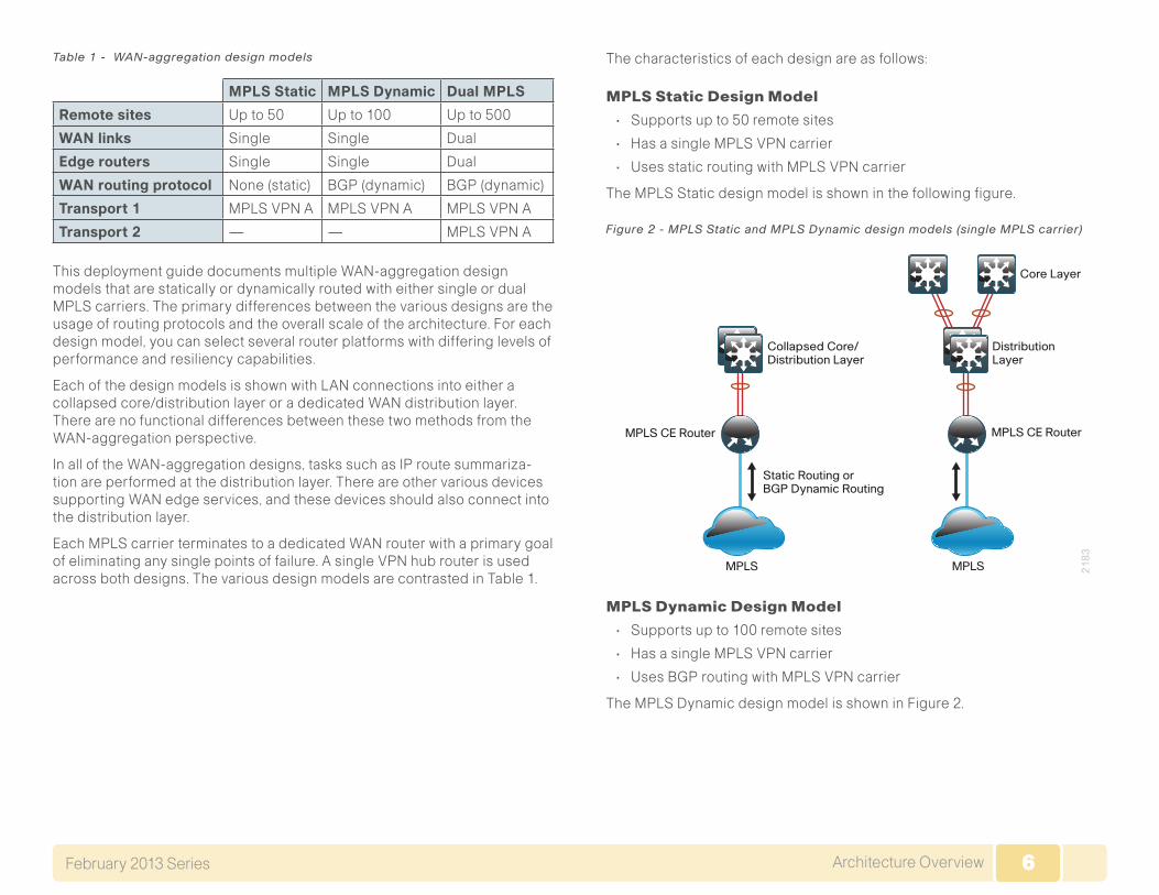
Table 1 - WAN-aggregation design models
MPLS Static MPLS Dynamic Dual MPLS
Remote sites Up to 50 Up to 100 Up to 500
WAN links Single Single Dual
Edge routers Single Single Dual
WAN routing protocol None (static) BGP (dynamic) BGP (dynamic)
Transport 1 MPLS VPN A MPLS VPN A MPLS VPN A
Transport 2 — — MPLS VPN A
This deployment guide documents multiple WAN-aggregation design models that are statically or dynamically routed with either single or dual MPLS carriers. The primary differences between the various designs are the usage of routing protocols and the overall scale of the architecture. For each design model, you can select several router platforms with differing levels of performance and resiliency capabilities.
Each of the design models is shown with LAN connections into either a collapsed core/distribution layer or a dedicated WAN distribution layer. There are no functional differences between these two methods from the WAN-aggregation perspective.
In all of the WAN-aggregation designs, tasks such as IP route summariza-tion are performed at the distribution layer. There are other various devices supporting WAN edge services, and these devices should also connect into the distribution layer.
Each MPLS carrier terminates to a dedicated WAN router with a primary goal of eliminating any single points of failure. A single VPN hub router is used across both designs. The various design models are contrasted in Table 1.
The characteristics of each design are as follows:
MPLS Static Design Model
• Supports up to 50 remote sites
• Has a single MPLS VPN carrier
• Uses static routing with MPLS VPN carrier
The MPLS Static design model is shown in the following figure.
Figure 2 - MPLS Static and MPLS Dynamic design models (single MPLS carrier)
21
83
MPLS
MPLS CE Router MPLS CE Router
Static Routing orBGP Dynamic Routing
Collapsed Core/Distribution Layer
MPLS
Core Layer
DistributionLayer
MPLS Dynamic Design Model
• Supports up to 100 remote sites
• Has a single MPLS VPN carrier
• Uses BGP routing with MPLS VPN carrier
The MPLS Dynamic design model is shown in Figure 2.
7Architecture OverviewFebruary 2013 Series 7
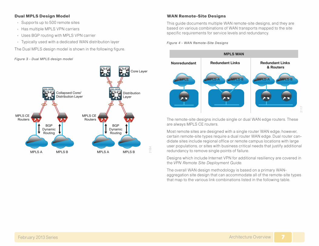
Dual MPLS Design Model
• Supports up to 500 remote sites
• Has multiple MPLS VPN carriers
• Uses BGP routing with MPLS VPN carrier
• Typically used with a dedicated WAN distribution layer
The Dual MPLS design model is shown in the following figure.
Figure 3 - Dual MPLS design model
21
84
MPLS CERouters
BGPDynamicRouting
MPLS A MPLS B
QFP QFP
MPLS CERouters
BGPDynamicRouting
MPLS A MPLS B
QFP QFP
Collapsed Core/Distribution Layer
DistributionLayer
Core Layer
WAN Remote-Site Designs
This guide documents multiple WAN remote-site designs, and they are based on various combinations of WAN transports mapped to the site specific requirements for service levels and redundancy.
Figure 4 - WAN Remote-Site Designs
21
17
Redundant Links Redundant Links & Routers
Nonredundant
MPLS MPLS-A MPLS-B MPLS-A MPLS-B
MPLS WAN
The remote-site designs include single or dual WAN edge routers. These are always MPLS CE routers.
Most remote sites are designed with a single router WAN edge; however, certain remote-site types require a dual router WAN edge. Dual router can-didate sites include regional office or remote campus locations with large user populations, or sites with business critical needs that justify additional redundancy to remove single points of failure.
Designs which include Internet VPN for additional resiliency are covered in the VPN Remote Site Deployment Guide.
The overall WAN design methodology is based on a primary WAN-aggregation site design that can accommodate all of the remote-site types that map to the various link combinations listed in the following table.
8Architecture OverviewFebruary 2013 Series 8
Table 2 - WAN remote-site transport options
WAN remote-site routers
WAN transports
Primary transport
Secondary transport
Single Single MPLS VPN A -
Single Dual MPLS VPN A MPLS VPN B
Dual Dual MPLS VPN A MPLS VPN B
The modular nature of the network design enables you to create design elements that you can replicate throughout the network.
Both WAN-aggregation designs and all of the WAN remote-site designs are standard building blocks in the overall design. Replication of the individual building blocks provides an easy way to scale the network and allows for a consistent deployment method.
WAN/LAN Interconnection
The primary role of the WAN is to interconnect primary site and remote-site LANs. The LAN discussion within this guide is limited to how the WAN-aggregation site LAN connects to the WAN-aggregation devices and how the remote-site LANs connect to the remote-site WAN devices. Specific details regarding the LAN components of the design are covered in the LAN Deployment Guide.
At remote sites, the LAN topology depends on the number of connected users and physical geography of the site. Large sites may require the use of a distribution layer to support multiple access layer switches. Other sites may only require an access layer switch directly connected to the WAN remote-site routers. The variants that are tested and documented in this guide are shown in the following table.
Table 3 - WAN remote-site LAN options
WAN remote-site routers WAN transports LAN topology
Single Single Access only
Distribution/access
Single Dual Access only
Distribution/access
Dual Dual Access only
Distribution/access
WAN Remote Sites—LAN Topology
For consistency and modularity, all WAN remote sites use the same VLAN assignment scheme, which is shown in the following table. This deployment guide uses a convention that is relevant to any location that has a single access switch and this model can also be easily scaled to additional access closets through the addition of a distribution layer.
Table 4 - WAN remote-sites—VLAN assignment
VLAN Usage Layer 2 access Layer 3 distribution/ access
VLAN 64 Data Yes -
VLAN 69 Voice Yes -
VLAN 99 Transit Yes
(dual router only)
Yes
(dual router only)
VLAN 50 Router link (1) - Yes
VLAN 54 Router link (2) - Yes
(dual router only)
Layer 2 Access
WAN remote sites that do not require additional distribution layer rout-ing devices are considered to be flat or from a LAN perspective they are considered unrouted Layer 2 sites. All Layer 3 services are provided by the attached WAN routers. The access switches, through the use of multiple VLANs, can support services such as data and voice. The design shown in the following figure illustrates the standardized VLAN assignment scheme. The benefits of this design are clear: all of the access switches can be configured identically, regardless of the number of sites in this configuration.
Access switches and their configuration are not included in this guide. The LAN Deployment Guide provides configuration details on the various access switching platforms.
IP subnets are assigned on a per-VLAN basis. This design only allocates subnets with a 255.255.255.0 netmask for the access layer, even if less than 254 IP addresses are required. (This model can be adjusted as necessary to other IP address schemes.) The connection between the router and the access switch must be configured for 802.1Q VLAN trunking with subinter
9Architecture OverviewFebruary 2013 Series 9
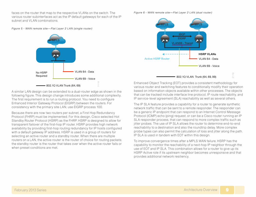
faces on the router that map to the respective VLANs on the switch. The various router subinterfaces act as the IP default gateways for each of the IP subnet and VLAN combinations.
Figure 5 - WAN remote site—Flat Layer 2 LAN (single router)
MPLS
No HSRPRequired
VLAN 64 - Data
802.1Q VLAN Trunk (64, 69)
VLAN 69 - Voice
21
18
A similar LAN design can be extended to a dual-router edge as shown in the following figure. This design change introduces some additional complexity. The first requirement is to run a routing protocol. You need to configure Enhanced Interior Gateway Protocol (EIGRP) between the routers. For consistency with the primary site LAN, use EIGRP process 100.
Because there are now two routers per subnet, a First Hop Redundancy Protocol (FHRP) must be implemented. For this design, Cisco selected Hot Standby Router Protocol (HSRP) as the FHRP. HSRP is designed to allow for transparent failover of the first-hop IP router. HSRP provides high network availability by providing first-hop routing redundancy for IP hosts configured with a default gateway IP address. HSRP is used in a group of routers for selecting an active router and a standby router. When there are multiple routers on a LAN, the active router is the router of choice for routing packets; the standby router is the router that takes over when the active router fails or when preset conditions are met.
Figure 6 - WAN remote site—Flat Layer 2 LAN (dual router)
MPLS MPLS
Active HSRP Router VLAN 64 - Data
VLAN99 - Transit
802.1Q VLAN Trunk (64, 69, 99)
VLAN 69 - Voice
21
19
HSRP VLANs
EIGRP
iBGP
Enhanced Object Tracking (EOT) provides a consistent methodology for various router and switching features to conditionally modify their operation based on information objects available within other processes. The objects that can be tracked include interface line protocol, IP route reachability, and IP service-level agreement (SLA) reachability as well as several others.
The IP SLA feature provides a capability for a router to generate synthetic network traffic that can be sent to a remote responder. The responder can be a generic IP endpoint that can respond to an Internet Control Message Protocol (ICMP) echo (ping) request, or can be a Cisco router running an IP SLA responder process, that can respond to more complex traffic such as jitter probes. The use of IP SLA allows the router to determine end-to-end reachability to a destination and also the roundtrip delay. More complex probe types can also permit the calculation of loss and jitter along the path. IP SLA is used in tandem with EOT within this design.
To improve convergence times after a MPLS WAN failure, HSRP has the capability to monitor the reachability of a next-hop IP neighbor through the use of EOT and IP SLA. This combination allows for a router to give up its HSRP Active role if its upstream neighbor becomes unresponsive and that provides additional network resiliency.
10Architecture OverviewFebruary 2013 Series 10
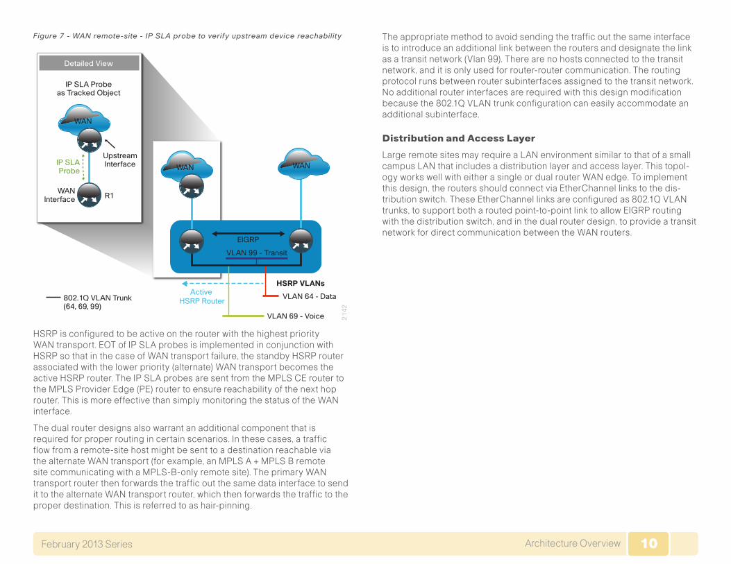
Figure 7 - WAN remote-site - IP SLA probe to verify upstream device reachability
WAN
Active HSRP Router
VLAN 64 - Data
VLAN 99 - Transit
802.1Q VLAN Trunk (64, 69, 99)
VLAN 69 - Voice 21
42
HSRP VLANs
EIGRP
IP SLAProbe
WANInterface R1
UpstreamInterface
WAN
IP SLA Probeas Tracked Object
WAN
Detailed View
HSRP is configured to be active on the router with the highest priority WAN transport. EOT of IP SLA probes is implemented in conjunction with HSRP so that in the case of WAN transport failure, the standby HSRP router associated with the lower priority (alternate) WAN transport becomes the active HSRP router. The IP SLA probes are sent from the MPLS CE router to the MPLS Provider Edge (PE) router to ensure reachability of the next hop router. This is more effective than simply monitoring the status of the WAN interface.
The dual router designs also warrant an additional component that is required for proper routing in certain scenarios. In these cases, a traffic flow from a remote-site host might be sent to a destination reachable via the alternate WAN transport (for example, an MPLS A + MPLS B remote site communicating with a MPLS-B-only remote site). The primary WAN transport router then forwards the traffic out the same data interface to send it to the alternate WAN transport router, which then forwards the traffic to the proper destination. This is referred to as hair-pinning.
The appropriate method to avoid sending the traffic out the same interface is to introduce an additional link between the routers and designate the link as a transit network (Vlan 99). There are no hosts connected to the transit network, and it is only used for router-router communication. The routing protocol runs between router subinterfaces assigned to the transit network. No additional router interfaces are required with this design modification because the 802.1Q VLAN trunk configuration can easily accommodate an additional subinterface.
Distribution and Access Layer
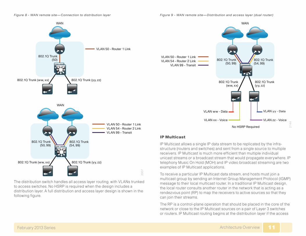
Large remote sites may require a LAN environment similar to that of a small campus LAN that includes a distribution layer and access layer. This topol-ogy works well with either a single or dual router WAN edge. To implement this design, the routers should connect via EtherChannel links to the dis-tribution switch. These EtherChannel links are configured as 802.1Q VLAN trunks, to support both a routed point-to-point link to allow EIGRP routing with the distribution switch, and in the dual router design, to provide a transit network for direct communication between the WAN routers.
11Architecture OverviewFebruary 2013 Series 11
Figure 8 - WAN remote site—Connection to distribution layer
20
07
WAN
WAN
VLAN 50 - Router 1 Link
VLAN 50 - Router 1 Link
802.1Q Trunk(50)
802.1Q Trunk (ww, xx) 802.1Q Trunk (yy, zz)
802.1Q Trunk (ww, xx)
802.1Q Trunk(50, 99)
802.1Q Trunk(54, 99)
VLAN 54 - Router 2 LinkVLAN 99 - Transit
802.1Q Trunk (yy, zz)
The distribution switch handles all access layer routing, with VLANs trunked to access switches. No HSRP is required when the design includes a distribution layer. A full distribution and access layer design is shown in the following figure.
Figure 9 - WAN remote site—Distribution and access layer (dual router)
21
44
WAN
VLAN 50 - Router 1 Link
802.1Q Trunk(ww, xx)
VLAN ww - Data
VLAN xx - Voice
VLAN yy - Data
VLAN zz - Voice
No HSRP Required
802.1Q Trunk(yy, zz)
802.1Q Trunk(50, 99)
802.1Q Trunk(54, 99)
VLAN 54 - Router 2 LinkVLAN 99 - Transit
IP Multicast
IP Multicast allows a single IP data stream to be replicated by the infra-structure (routers and switches) and sent from a single source to multiple receivers. IP Multicast is much more efficient than multiple individual unicast streams or a broadcast stream that would propagate everywhere. IP telephony Music On Hold (MOH) and IP video broadcast streaming are two examples of IP Multicast applications.
To receive a particular IP Multicast data stream, end hosts must join a multicast group by sending an Internet Group Management Protocol (IGMP) message to their local multicast router. In a traditional IP Multicast design, the local router consults another router in the network that is acting as a rendezvous point (RP) to map the receivers to active sources so that they can join their streams.
The RP is a control-plane operation that should be placed in the core of the network or close to the IP Multicast sources on a pair of Layer 3 switches or routers. IP Multicast routing begins at the distribution layer if the access
12Architecture OverviewFebruary 2013 Series 12
layer is Layer 2 and provides connectivity to the IP Multicast RP. In designs without a core layer, the distribution layer performs the RP function.
This design is fully enabled for a single global scope deployment of IP Multicast. The design uses an Anycast RP implementation strategy. This strategy provides load sharing and redundancy in Protocol Independent Multicast sparse mode (PIM SM) networks. Two RPs share the load for source registration and the ability to act as hot backup routers for each other.
The benefit of this strategy from the WAN perspective is that all IP routing devices within the WAN use an identical configuration referencing the Anycast RPs. IP PIM SM is enabled on all interfaces including loopbacks, VLANs, and subinterfaces.
Quality of ServiceMost users perceive the network as just a transport utility mechanism to shift data from point A to point B as fast as it can. Many sum this up as just “speeds and feeds.” While it is true that IP networks forward traffic on a best-effort basis by default, this type of routing only works well for applica-tions that adapt gracefully to variations in latency, jitter, and loss. However networks are multiservice by design and support real-time voice and video as well as data traffic. The difference is that real-time applications require packets to be delivered within specified loss, delay, and jitter parameters.
In reality, the network affects all traffic flows and must be aware of end-user requirements and services being offered. Even with unlimited bandwidth, time-sensitive applications are affected by jitter, delay, and packet loss. Quality of service (QoS) enables a multitude of user services and applica-tions to coexist on the same network.
Within the architecture, there are wired and wireless connectivity options that provide advanced classification, prioritizing, queuing, and congestion mechanisms as part of the integrated QoS to help ensure optimal use of network resources. This functionality allows for the differentiation of applica-tions, ensuring that each has the appropriate share of the network resources to protect the user experience and ensure the consistent operations of business critical applications.
QoS is an essential function of the network infrastructure devices used throughout this architecture. QoS enables a multitude of user services and applications, including real-time voice, high-quality video, and delay-sensi-tive data to coexist on the same network. In order for the network to provide predictable, measurable, and sometimes guaranteed services, it must man-age bandwidth, delay, jitter, and loss parameters. Even if you do not require
QoS for your current applications, you can use QoS for management and network protocols to protect the network functionality and manageability under normal and congested traffic conditions.
The goal of this design is to provide sufficient classes of service to allow you to add voice, interactive video, critical data applications, and manage-ment traffic to the network, either during the initial deployment or later with minimum system impact and engineering effort.
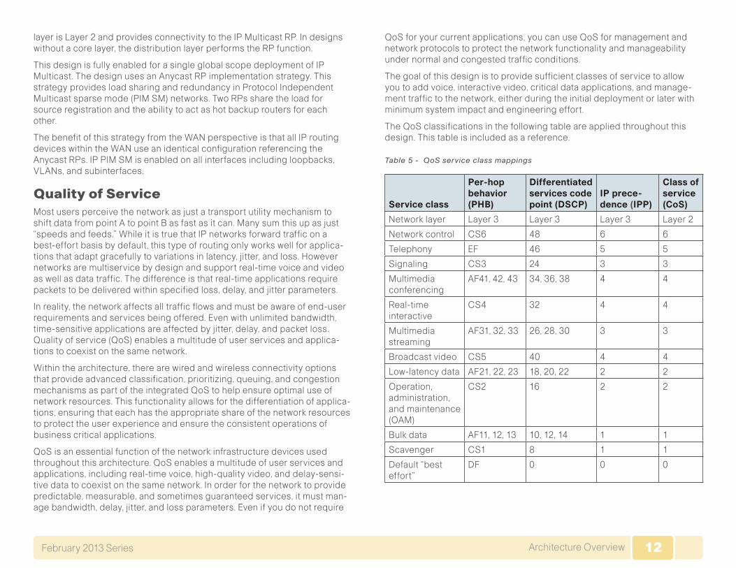
The QoS classifications in the following table are applied throughout this design. This table is included as a reference.
Table 5 - QoS service class mappings
Service class
Per-hop behavior (PHB)
Differentiated services code point (DSCP)
IP prece-dence (IPP)
Class of service (CoS)
Network layer Layer 3 Layer 3 Layer 3 Layer 2
Network control CS6 48 6 6
Telephony EF 46 5 5
Signaling CS3 24 3 3
Multimedia conferencing
AF41, 42, 43 34, 36, 38 4 4
Real-time interactive
CS4 32 4 4
Multimedia streaming
AF31, 32, 33 26, 28, 30 3 3
Broadcast video CS5 40 4 4
Low-latency data AF21, 22, 23 18, 20, 22 2 2
Operation, administration, and maintenance (OAM)
CS2 16 2 2
Bulk data AF11, 12, 13 10, 12, 14 1 1
Scavenger CS1 8 1 1
Default “best effort”
DF 0 0 0
13Deploying the WANFebruary 2013 Series 13
Deploying the WAN
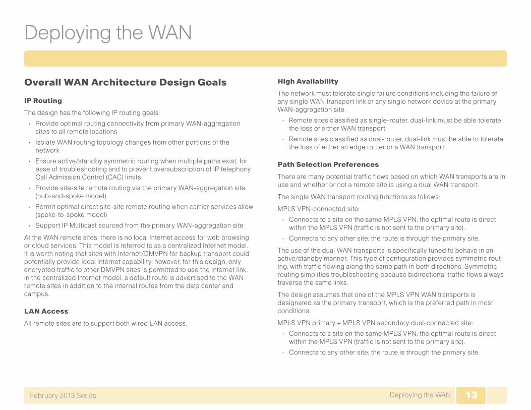
Overall WAN Architecture Design Goals
IP Routing
The design has the following IP routing goals:
• Provide optimal routing connectivity from primary WAN-aggregation sites to all remote locations
• Isolate WAN routing topology changes from other portions of the network
• Ensure active/standby symmetric routing when multiple paths exist, for ease of troubleshooting and to prevent oversubscription of IP telephony Call Admission Control (CAC) limits
• Provide site-site remote routing via the primary WAN-aggregation site (hub-and-spoke model)
• Permit optimal direct site-site remote routing when carrier services allow (spoke-to-spoke model)
• Support IP Multicast sourced from the primary WAN-aggregation site
At the WAN remote sites, there is no local Internet access for web browsing or cloud services. This model is referred to as a centralized Internet model. It is worth noting that sites with Internet/DMVPN for backup transport could potentially provide local Internet capability; however, for this design, only encrypted traffic to other DMVPN sites is permitted to use the Internet link. In the centralized Internet model, a default route is advertised to the WAN remote sites in addition to the internal routes from the data center and campus.
LAN Access
All remote sites are to support both wired LAN access.
High Availability
The network must tolerate single failure conditions including the failure of any single WAN transport link or any single network device at the primary WAN-aggregation site.
• Remote sites classified as single-router, dual-link must be able tolerate the loss of either WAN transport.
• Remote sites classified as dual-router, dual-link must be able to tolerate the loss of either an edge router or a WAN transport.
Path Selection Preferences
There are many potential traffic flows based on which WAN transports are in use and whether or not a remote site is using a dual WAN transport.
The single WAN transport routing functions as follows:
MPLS VPN-connected site:
• Connects to a site on the same MPLS VPN; the optimal route is direct within the MPLS VPN (traffic is not sent to the primary site).
• Connects to any other site; the route is through the primary site.
The use of the dual WAN transports is specifically tuned to behave in an active/standby manner. This type of configuration provides symmetric rout-ing, with traffic flowing along the same path in both directions. Symmetric routing simplifies troubleshooting because bidirectional traffic flows always traverse the same links.
The design assumes that one of the MPLS VPN WAN transports is designated as the primary transport, which is the preferred path in most conditions.
MPLS VPN primary + MPLS VPN secondary dual-connected site:
• Connects to a site on the same MPLS VPN; the optimal route is direct within the MPLS VPN (traffic is not sent to the primary site).
• Connects to any other site; the route is through the primary site.
14Deploying the WANFebruary 2013 Series 14
Quality of Service (QoS)
The network must ensure that business applications perform across the WAN during times of network congestion. Traffic must be classified and queued and the WAN connection must be shaped to operate within the capabilities of the connection. When the WAN design uses a service pro-vider offering with QoS, the WAN edge QoS classification and treatment must align to the service provider offering to ensure consistent end-to-end QoS treatment of traffic.
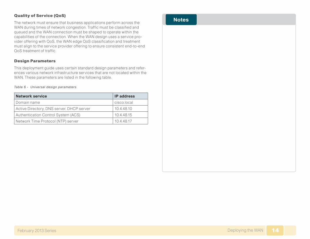
Design Parameters
This deployment guide uses certain standard design parameters and refer-ences various network infrastructure services that are not located within the WAN. These parameters are listed in the following table.
Table 6 - Universal design parameters
Network service IP address
Domain name cisco.local
Active Directory, DNS server, DHCP server 10.4.48.10
Authentication Control System (ACS) 10.4.48.15
Network Time Protocol (NTP) server 10.4.48.17
15Deploying an MPLS WANFebruary 2013 Series 15
Deploying an MPLS WAN
Business OverviewFor remote-site users to effectively support the business, organizations require that the WAN provide sufficient performance and reliability. Although most of the applications and services that the remote-site worker uses are centrally located, the WAN design must provide a common resource access experience to the workforce regardless of location.
To control operational costs, the WAN must support the convergence of voice, video, and data transport onto a single, centrally managed infrastruc-ture. As organizations move into multinational or global business markets, they require a flexible network design that allows for country-specific access requirements and controls complexity. The ubiquity of carrier-pro-vided MPLS networks makes it a required consideration for an organization building a WAN.
To reduce the time needed to deploy new technologies that support emerg-ing business applications and communications, the WAN architecture requires a flexible design. The ability to easily scale bandwidth or to add additional sites or resilient links makes MPLS an effective WAN transport for growing organizations.
Technology Overview
WAN-Aggregation—MPLS CE Routers
The MPLS WAN designs are intended to support up to 500 remote sites with a combined aggregate WAN bandwidth of up to 1.0 Gbps. The most critical devices are the WAN routers that are responsible for reliable IP forwarding and QoS. The amount of bandwidth required at the WAN-aggregation site determines which model of router to use. The choice of whether to imple-ment a single router or dual router is determined by the number of carriers that are required in order to provide connections to all of the remote sites.
Cisco ASR 1000 Series Aggregation Services Routers represent the next-generation, modular, services-integrated Cisco routing platform. They are specifically designed for WAN aggregation, with the flexibility to support a wide range of 3- to 16-mpps (millions of packets per second) packet-forwarding capabilities, 2.5- to 40-Gbps system bandwidth performance, and scaling.
The Cisco ASR 1000 Series is fully modular from both hardware and soft-ware perspectives, and the routers have all the elements of a true carrier-class routing product that serves both enterprise and service-provider networks.
This design uses the following routers as MPLS CE routers:
• Cisco ASR 1002 Aggregation Services Router configured with an Embedded Service Processor 5 (ESP5)
• Cisco ASR 1001 Aggregation Services Router fixed configuration with a 2.5 Gbps Embedded Service Processor
• Cisco 3945 Integrated Services Router
• Cisco 3925 Integrated Services Router
All of the design models can be constructed using any of the MPLS CE routers listed in Table 7. You should consider the following: the forwarding performance of the router using an Ethernet WAN deployment with broad services enabled, the router’s alignment with the suggested design model, and the number of remote sites.
16Deploying an MPLS WANFebruary 2013 Series 16
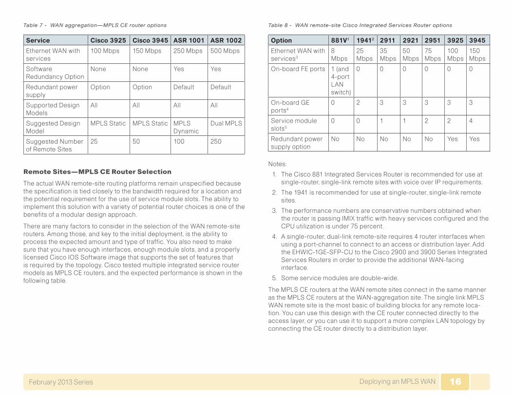
Table 7 - WAN aggregation—MPLS CE router options
Service Cisco 3925 Cisco 3945 ASR 1001 ASR 1002
Ethernet WAN with services
100 Mbps 150 Mbps 250 Mbps 500 Mbps
Software Redundancy Option
None None Yes Yes
Redundant power supply
Option Option Default Default
Supported Design Models
All All All All
Suggested Design Model
MPLS Static MPLS Static MPLS Dynamic
Dual MPLS
Suggested Number of Remote Sites
25 50 100 250
Remote Sites—MPLS CE Router Selection
The actual WAN remote-site routing platforms remain unspecified because the specification is tied closely to the bandwidth required for a location and the potential requirement for the use of service module slots. The ability to implement this solution with a variety of potential router choices is one of the benefits of a modular design approach.
There are many factors to consider in the selection of the WAN remote-site routers. Among those, and key to the initial deployment, is the ability to process the expected amount and type of traffic. You also need to make sure that you have enough interfaces, enough module slots, and a properly licensed Cisco IOS Software image that supports the set of features that is required by the topology. Cisco tested multiple integrated service router models as MPLS CE routers, and the expected performance is shown in the following table.
Table 8 - WAN remote-site Cisco Integrated Services Router options
Option 881V1 19412 2911 2921 2951 3925 3945
Ethernet WAN with services3
8 Mbps
25 Mbps
35 Mbps
50 Mbps
75 Mbps
100 Mbps
150 Mbps
On-board FE ports 1 (and 4-port LAN switch)
0 0 0 0 0 0
On-board GE ports4
0 2 3 3 3 3 3
Service module slots5
0 0 1 1 2 2 4
Redundant power supply option
No No No No No Yes Yes
Notes:
1. The Cisco 881 Integrated Services Router is recommended for use at single-router, single-link remote sites with voice over IP requirements.
2. The 1941 is recommended for use at single-router, single-link remote sites.
3. The performance numbers are conservative numbers obtained when the router is passing IMIX traffic with heavy services configured and the CPU utilization is under 75 percent.
4. A single-router, dual-link remote-site requires 4 router interfaces when using a port-channel to connect to an access or distribution layer. Add the EHWIC-1GE-SFP-CU to the Cisco 2900 and 3900 Series Integrated Services Routers in order to provide the additional WAN-facing interface.
5. Some service modules are double-wide.
The MPLS CE routers at the WAN remote sites connect in the same manner as the MPLS CE routers at the WAN-aggregation site. The single link MPLS WAN remote site is the most basic of building blocks for any remote loca-tion. You can use this design with the CE router connected directly to the access layer, or you can use it to support a more complex LAN topology by connecting the CE router directly to a distribution layer.
17Deploying an MPLS WANFebruary 2013 Series 17
The IP routing is straightforward and can be handled entirely by using static routes at the WAN-aggregation site and static default routes at the remote site. However, there is significant value to configuring this type of site with dynamic routing and this approach is used for the MPLS Dynamic and Dual MPLS designs.
Dynamic routing makes it easy to add or modify IP networks at the remote site because any changes are immediately propagated to the rest of the network. MPLS VPN-connected sites require static routing to be handled by the carrier, and any changes or modifications require a change request to the carrier.
The smaller scale MPLS Static design uses static routing and relies on the carrier to configure the additional required static routes on the PE routers.
We recommend that you select the Dual MPLS or MPLS Dynamic designs if you intend to use resilient WAN links or want to be able to modify your routing configuration without carrier involvement.
Tech Tip
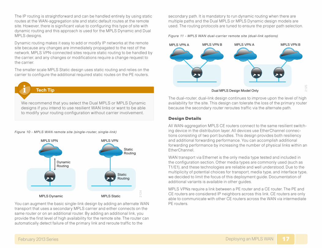
Figure 10 - MPLS WAN remote site (single-router, single-link)
21
24
MPLS VPN
DynamicRouting
MPLS VPN
StaticRouting
StaticRouting
MPLS Dynamic MPLS Static
You can augment the basic single-link design by adding an alternate WAN transport that uses a secondary MPLS carrier and either connects on the same router or on an additional router. By adding an additional link, you provide the first level of high availability for the remote site. The router can automatically detect failure of the primary link and reroute traffic to the
secondary path. It is mandatory to run dynamic routing when there are multiple paths and the Dual MPLS or MPLS Dynamic design models are used. The routing protocols are tuned to ensure the proper path selection.
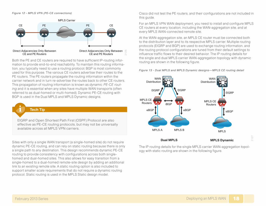
Figure 11 - MPLS WAN dual-carrier remote site (dual-link options)
MPLS VPN A MPLS VPN A MPLS VPN BMPLS VPN B
21
25
Dual MPLS Design Model Only
The dual-router, dual-link design continues to improve upon the level of high availability for the site. This design can tolerate the loss of the primary router because the secondary router reroutes traffic via the alternate path.
Design Details
All WAN-aggregation MPLS CE routers connect to the same resilient switch-ing device in the distribution layer. All devices use EtherChannel connec-tions consisting of two port bundles. This design provides both resiliency and additional forwarding performance. You can accomplish additional forwarding performance by increasing the number of physical links within an EtherChannel.
WAN transport via Ethernet is the only media type tested and included in the configuration section. Other media types are commonly used (such as T1/E1), and these technologies are reliable and well understood. Due to the multiplicity of potential choices for transport, media type, and interface type, we decided to limit the focus of this deployment guide. Documentation of additional variants is available in other guides.
MPLS VPNs require a link between a PE router and a CE router. The PE and CE routers are considered IP neighbors across this link. CE routers are only able to communicate with other CE routers across the WAN via intermediate PE routers.
18Deploying an MPLS WANFebruary 2013 Series 18
Figure 12 - MPLS VPN (PE-CE connections)
PE
MPLS Carrier
CE
Direct Adjacencies Only BetweenCE and PE Routers 2
12
6
CEPE
Direct Adjacencies Only BetweenCE and PE Routers
Both the PE and CE routers are required to have sufficient IP-routing infor-mation to provide end-to-end reachability. To maintain this routing informa-tion, you typically need to use a routing protocol; BGP is most commonly used for this purpose. The various CE routers advertise their routes to the PE routers. The PE routers propagate the routing information within the carrier network and in turn re-advertise the routes back to other CE routers. This propagation of routing information is known as dynamic PE-CE rout-ing and it is essential when any sites have multiple WAN transports (often referred to as dual-homed or multi-homed). Dynamic PE-CE routing with BGP is used in the Dual MPLS and MPLS Dynamic designs.
EIGRP and Open Shortest Path First (OSPF) Protocol are also effective as PE-CE routing protocols, but may not be universally available across all MPLS VPN carriers.
Tech Tip
Sites with only a single WAN transport (a single-homed site) do not require dynamic PE-CE routing, and can rely on static routing because there is only a single path to any destination. This design recommends dynamic PE-CE routing to provide consistency with configurations across both single-homed and dual-homed sites. This also allows for easy transition from a single-homed to a dual-homed remote-site design by adding an additional link to an existing remote site. A static routing option is also included to support smaller scale requirements that do not require a dynamic routing protocol. Static routing is used in the MPLS Static design model.
Cisco did not test the PE routers, and their configurations are not included in this guide.
For an MPLS VPN WAN deployment, you need to install and configure MPLS CE routers at every location, including the WAN-aggregation site, and at every MPLS WAN-connected remote site.
At the WAN-aggregation site, an MPLS CE router must be connected both to the distribution layer and to its respective MPLS carrier. Multiple routing protocols (EIGRP and BGP) are used to exchange routing information, and the routing protocol configurations are tuned from their default settings to influence traffic flows to their desired behavior. The IP routing details for the single and dual MPLS carrier WAN-aggregation topology with dynamic routing are shown in the following figure.
Figure 13 - Dual MPLS and MPLS Dynamic designs—MPLS CE routing detail
21
27
MPLS CERouters
Dual MPLS
WANDistribution
eBGP
MPLS A MPLS B MPLS
iBGP
eBGP
QFP QFP
MPLS CERouters
MPLS Dynamic
EIGRP
eBGP
QFP
EIGRP EIGRP
WANDistribution
The IP routing details for the single MPLS carrier WAN-aggregation topol-ogy with static routing are shown in the following figure.
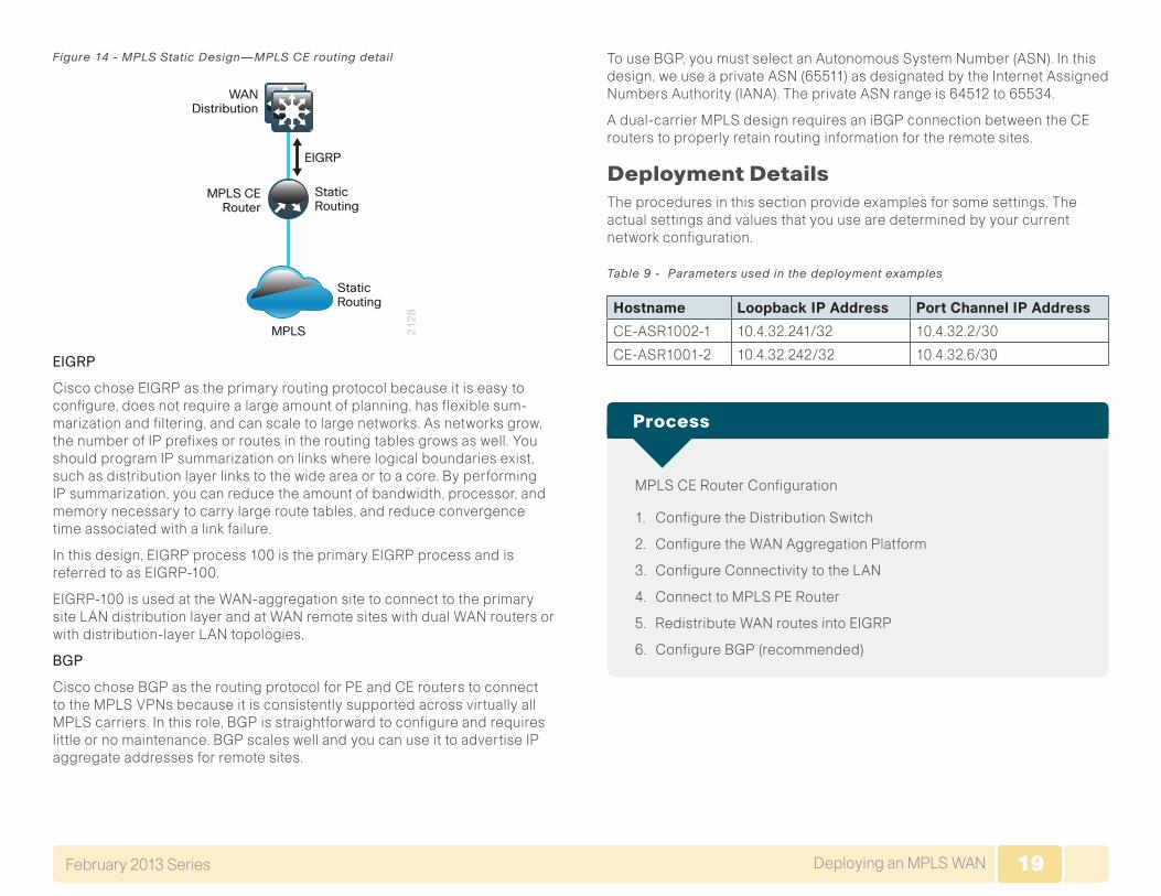
19Deploying an MPLS WANFebruary 2013 Series 19
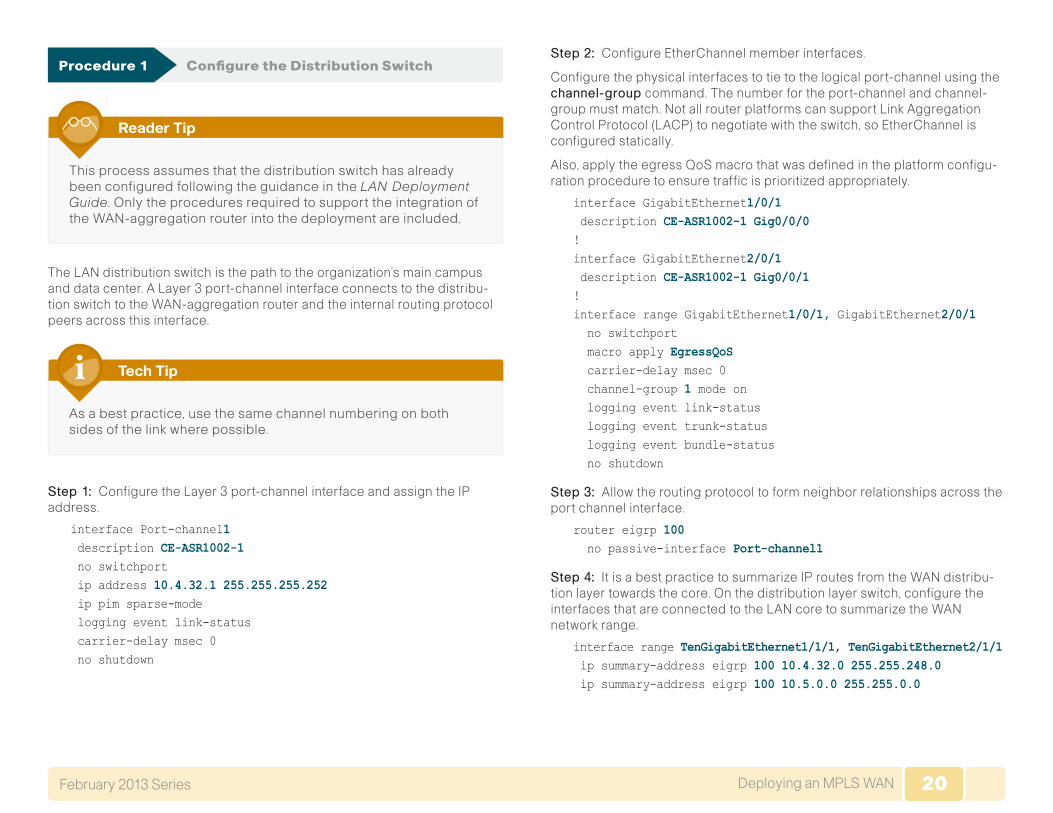
Figure 14 - MPLS Static Design—MPLS CE routing detail
21
28
MPLS CERouter
MPLS
StaticRouting
StaticRouting
EIGRP
WANDistribution
EIGRP
Cisco chose EIGRP as the primary routing protocol because it is easy to configure, does not require a large amount of planning, has flexible sum-marization and filtering, and can scale to large networks. As networks grow, the number of IP prefixes or routes in the routing tables grows as well. You should program IP summarization on links where logical boundaries exist, such as distribution layer links to the wide area or to a core. By performing IP summarization, you can reduce the amount of bandwidth, processor, and memory necessary to carry large route tables, and reduce convergence time associated with a link failure.
In this design, EIGRP process 100 is the primary EIGRP process and is referred to as EIGRP-100.
EIGRP-100 is used at the WAN-aggregation site to connect to the primary site LAN distribution layer and at WAN remote sites with dual WAN routers or with distribution-layer LAN topologies.
BGP
Cisco chose BGP as the routing protocol for PE and CE routers to connect to the MPLS VPNs because it is consistently supported across virtually all MPLS carriers. In this role, BGP is straightforward to configure and requires little or no maintenance. BGP scales well and you can use it to advertise IP aggregate addresses for remote sites.
To use BGP, you must select an Autonomous System Number (ASN). In this design, we use a private ASN (65511) as designated by the Internet Assigned Numbers Authority (IANA). The private ASN range is 64512 to 65534.
A dual-carrier MPLS design requires an iBGP connection between the CE routers to properly retain routing information for the remote sites.
Deployment Details The procedures in this section provide examples for some settings. The actual settings and values that you use are determined by your current network configuration.
Table 9 - Parameters used in the deployment examples
Hostname Loopback IP Address Port Channel IP Address
CE-ASR1002-1 10.4.32.241/32 10.4.32.2/30
CE-ASR1001-2 10.4.32.242/32 10.4.32.6/30
MPLS CE Router Configuration
1. Configure the Distribution Switch
2. Configure the WAN Aggregation Platform
3. Configure Connectivity to the LAN
4. Connect to MPLS PE Router
5. Redistribute WAN routes into EIGRP
6. Configure BGP (recommended)
Process
20Deploying an MPLS WANFebruary 2013 Series 20
Procedure 1 Configure the Distribution Switch
This process assumes that the distribution switch has already been configured following the guidance in the LAN Deployment Guide. Only the procedures required to support the integration of the WAN-aggregation router into the deployment are included.
Reader Tip
The LAN distribution switch is the path to the organization’s main campus and data center. A Layer 3 port-channel interface connects to the distribu-tion switch to the WAN-aggregation router and the internal routing protocol peers across this interface.
As a best practice, use the same channel numbering on both sides of the link where possible.
Tech Tip
Step 1: Configure the Layer 3 port-channel interface and assign the IP address.
interface Port-channel1 description CE-ASR1002-1 no switchport ip address 10.4.32.1 255.255.255.252 ip pim sparse-mode logging event link-status carrier-delay msec 0 no shutdown
Step 2: Configure EtherChannel member interfaces.
Configure the physical interfaces to tie to the logical port-channel using the channel-group command. The number for the port-channel and channel-group must match. Not all router platforms can support Link Aggregation Control Protocol (LACP) to negotiate with the switch, so EtherChannel is configured statically.
Also, apply the egress QoS macro that was defined in the platform configu-ration procedure to ensure traffic is prioritized appropriately.
interface GigabitEthernet1/0/1 description CE-ASR1002-1 Gig0/0/0!interface GigabitEthernet2/0/1 description CE-ASR1002-1 Gig0/0/1!interface range GigabitEthernet1/0/1, GigabitEthernet2/0/1 no switchport macro apply EgressQoS carrier-delay msec 0 channel-group 1 mode on logging event link-status logging event trunk-status logging event bundle-status no shutdown
Step 3: Allow the routing protocol to form neighbor relationships across the port channel interface.
router eigrp 100 no passive-interface Port-channel1
Step 4: It is a best practice to summarize IP routes from the WAN distribu-tion layer towards the core. On the distribution layer switch, configure the interfaces that are connected to the LAN core to summarize the WAN network range.
interface range TenGigabitEthernet1/1/1, TenGigabitEthernet2/1/1 ip summary-address eigrp 100 10.4.32.0 255.255.248.0 ip summary-address eigrp 100 10.5.0.0 255.255.0.0
21Deploying an MPLS WANFebruary 2013 Series 21
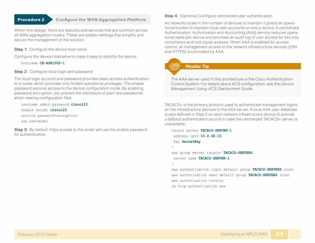
Procedure 2 Configure the WAN Aggregation Platform
Within this design, there are features and services that are common across all WAN aggregation routers. These are system settings that simplify and secure the management of the solution.
Step 1: Configure the device host name.
Configure the device hostname to make it easy to identify the device.
hostname CE-ASR1002-1
Step 2: Configure local login and password.
The local login account and password provides basic access authentication to a router, which provides only limited operational privileges. The enable password secures access to the device configuration mode. By enabling password encryption, you prevent the disclosure of plain text passwords when viewing configuration files.
username admin password c1sco123enable secret c1sco123service password-encryptionaaa new-model
Step 3: By default, https access to the router will use the enable password for authentication.
Step 4: (Optional) Configure centralized user authentication.
As networks scale in the number of devices to maintain it poses an opera-tional burden to maintain local user accounts on every device. A centralized Authentication, Authorization and Accounting (AAA) service reduces opera-tional tasks per device and provides an audit log of user access for security compliance and root cause analysis. When AAA is enabled for access control, all management access to the network infrastructure devices (SSH and HTTPS) is controlled by AAA.
The AAA server used in this architecture is the Cisco Authentication Control System. For details about ACS configuration, see the Device Management Using ACS Deployment Guide.
Reader Tip
TACACS+ is the primary protocol used to authenticate management logins on the infrastructure devices to the AAA server. A local AAA user database is also defined in Step 2 on each network infrastructure device to provide a fallback authentication source in case the centralized TACACS+ server is unavailable.
tacacs server TACACS-SERVER-1 address ipv4 10.4.48.15 key SecretKey!aaa group server tacacs+ TACACS-SERVERS server name TACACS-SERVER-1!aaa authentication login default group TACACS-SERVERS localaaa authorization exec default group TACACS-SERVERS localaaa authorization consoleip http authentication aaa
22Deploying an MPLS WANFebruary 2013 Series 22
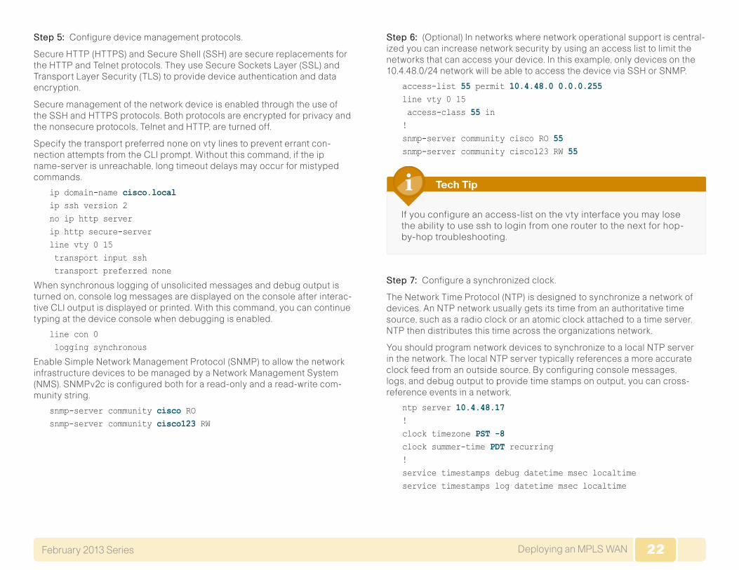
Step 5: Configure device management protocols.
Secure HTTP (HTTPS) and Secure Shell (SSH) are secure replacements for the HTTP and Telnet protocols. They use Secure Sockets Layer (SSL) and Transport Layer Security (TLS) to provide device authentication and data encryption.
Secure management of the network device is enabled through the use of the SSH and HTTPS protocols. Both protocols are encrypted for privacy and the nonsecure protocols, Telnet and HTTP, are turned off.
Specify the transport preferred none on vty lines to prevent errant con-nection attempts from the CLI prompt. Without this command, if the ip name-server is unreachable, long timeout delays may occur for mistyped commands.
ip domain-name cisco.localip ssh version 2no ip http serverip http secure-serverline vty 0 15 transport input ssh transport preferred none
When synchronous logging of unsolicited messages and debug output is turned on, console log messages are displayed on the console after interac-tive CLI output is displayed or printed. With this command, you can continue typing at the device console when debugging is enabled.
line con 0 logging synchronous
Enable Simple Network Management Protocol (SNMP) to allow the network infrastructure devices to be managed by a Network Management System (NMS). SNMPv2c is configured both for a read-only and a read-write com-munity string.
snmp-server community cisco RO snmp-server community cisco123 RW
Step 6: (Optional) In networks where network operational support is central-ized you can increase network security by using an access list to limit the networks that can access your device. In this example, only devices on the 10.4.48.0/24 network will be able to access the device via SSH or SNMP.
access-list 55 permit 10.4.48.0 0.0.0.255line vty 0 15 access-class 55 in !snmp-server community cisco RO 55 snmp-server community cisco123 RW 55
If you configure an access-list on the vty interface you may lose the ability to use ssh to login from one router to the next for hop-by-hop troubleshooting.
Tech Tip
Step 7: Configure a synchronized clock.
The Network Time Protocol (NTP) is designed to synchronize a network of devices. An NTP network usually gets its time from an authoritative time source, such as a radio clock or an atomic clock attached to a time server. NTP then distributes this time across the organizations network.
You should program network devices to synchronize to a local NTP server in the network. The local NTP server typically references a more accurate clock feed from an outside source. By configuring console messages, logs, and debug output to provide time stamps on output, you can cross-reference events in a network.
ntp server 10.4.48.17!clock timezone PST -8 clock summer-time PDT recurring !service timestamps debug datetime msec localtimeservice timestamps log datetime msec localtime
23Deploying an MPLS WANFebruary 2013 Series 23
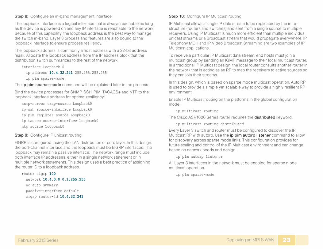
Step 8: Configure an in-band management interface.
The loopback interface is a logical interface that is always reachable as long as the device is powered on and any IP interface is reachable to the network. Because of this capability, the loopback address is the best way to manage the switch in-band. Layer 3 process and features are also bound to the loopback interface to ensure process resiliency.
The loopback address is commonly a host address with a 32-bit address mask. Allocate the loopback address from the IP address block that the distribution switch summarizes to the rest of the network.
interface Loopback 0 ip address 10.4.32.241 255.255.255.255 ip pim sparse-mode
The ippimsparse-mode command will be explained later in the process.
Bind the device processes for SNMP, SSH, PIM, TACACS+ and NTP to the loopback interface address for optimal resiliency:
snmp-server trap-source Loopback0ip ssh source-interface Loopback0ip pim register-source Loopback0ip tacacs source-interface Loopback0ntp source Loopback0
Step 9: Configure IP unicast routing.
EIGRP is configured facing the LAN distribution or core layer. In this design, the port-channel interface and the loopback must be EIGRP interfaces. The loopback may remain a passive interface. The network range must include both interface IP addresses, either in a single network statement or in multiple network statements. This design uses a best practice of assigning the router ID to a loopback address.
router eigrp 100 network 10.4.0.0 0.1.255.255 no auto-summary passive-interface default eigrp router-id 10.4.32.241
Step 10: Configure IP Multicast routing.
IP Multicast allows a single IP data stream to be replicated by the infra-structure (routers and switches) and sent from a single source to multiple receivers. Using IP Multicast is much more efficient than multiple individual unicast streams or a Broadcast stream that would propagate everywhere. IP Telephony MOH and IP Video Broadcast Streaming are two examples of IP Multicast applications.
To receive a particular IP Multicast data stream, end hosts must join a multicast group by sending an IGMP message to their local multicast router. In a traditional IP Multicast design, the local router consults another router in the network that is acting as an RP to map the receivers to active sources so they can join their streams.
In this design, which is based on sparse mode multicast operation, Auto RP is used to provide a simple yet scalable way to provide a highly resilient RP environment.
Enable IP Multicast routing on the platforms in the global configuration mode.
ip multicast-routing
The Cisco ASR1000 Series router requires the distributed keyword.
ip multicast-routing distributed
Every Layer 3 switch and router must be configured to discover the IP Multicast RP with autorp. Use the ippimautorplistener command to allow for discovery across sparse mode links. This configuration provides for future scaling and control of the IP Multicast environment and can change based on network needs and design.
ip pim autorp listener
All Layer 3 interfaces in the network must be enabled for sparse mode multicast operation.
ip pim sparse-mode
24Deploying an MPLS WANFebruary 2013 Series 24
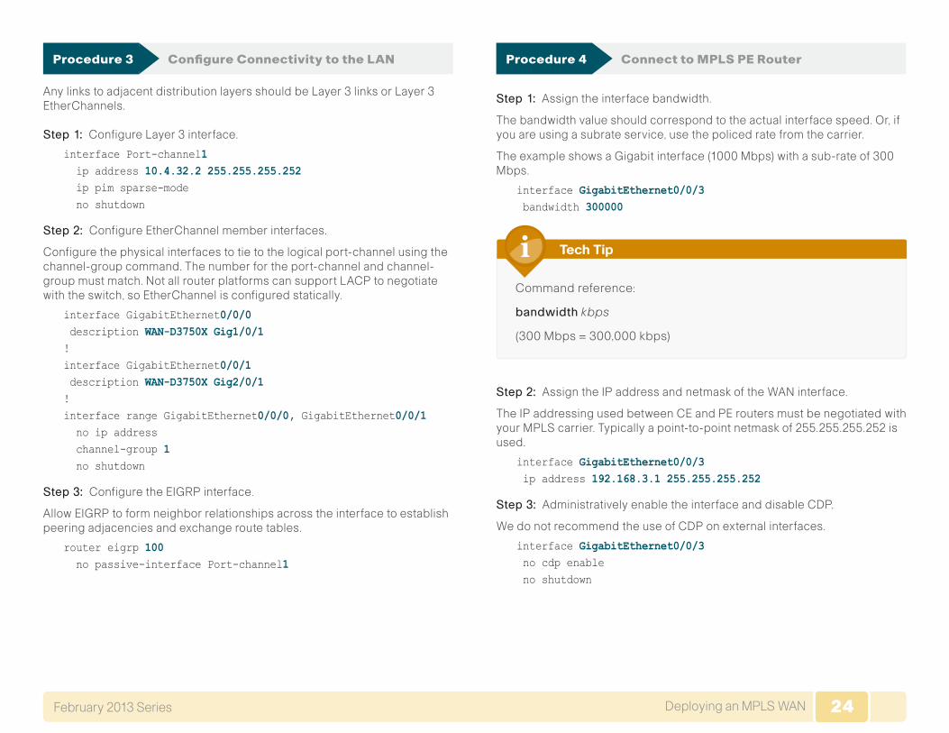
Procedure 3 Configure Connectivity to the LAN
Any links to adjacent distribution layers should be Layer 3 links or Layer 3 EtherChannels.
Step 1: Configure Layer 3 interface.
interface Port-channel1 ip address 10.4.32.2 255.255.255.252 ip pim sparse-mode no shutdown
Step 2: Configure EtherChannel member interfaces.
Configure the physical interfaces to tie to the logical port-channel using the channel-group command. The number for the port-channel and channel-group must match. Not all router platforms can support LACP to negotiate with the switch, so EtherChannel is configured statically.
interface GigabitEthernet0/0/0 description WAN-D3750X Gig1/0/1!interface GigabitEthernet0/0/1 description WAN-D3750X Gig2/0/1!interface range GigabitEthernet0/0/0, GigabitEthernet0/0/1 no ip address channel-group 1 no shutdown
Step 3: Configure the EIGRP interface.
Allow EIGRP to form neighbor relationships across the interface to establish peering adjacencies and exchange route tables.
router eigrp 100 no passive-interface Port-channel1
Procedure 4 Connect to MPLS PE Router
Step 1: Assign the interface bandwidth.
The bandwidth value should correspond to the actual interface speed. Or, if you are using a subrate service, use the policed rate from the carrier.
The example shows a Gigabit interface (1000 Mbps) with a sub-rate of 300 Mbps.
interface GigabitEthernet0/0/3 bandwidth 300000
Command reference:
bandwidth kbps
(300 Mbps = 300,000 kbps)
Tech Tip
Step 2: Assign the IP address and netmask of the WAN interface.
The IP addressing used between CE and PE routers must be negotiated with your MPLS carrier. Typically a point-to-point netmask of 255.255.255.252 is used.
interface GigabitEthernet0/0/3 ip address 192.168.3.1 255.255.255.252
Step 3: Administratively enable the interface and disable CDP.
We do not recommend the use of CDP on external interfaces.
interface GigabitEthernet0/0/3 no cdp enable no shutdown
25Deploying an MPLS WANFebruary 2013 Series 25
Procedure 5 Redistribute WAN routes into EIGRP
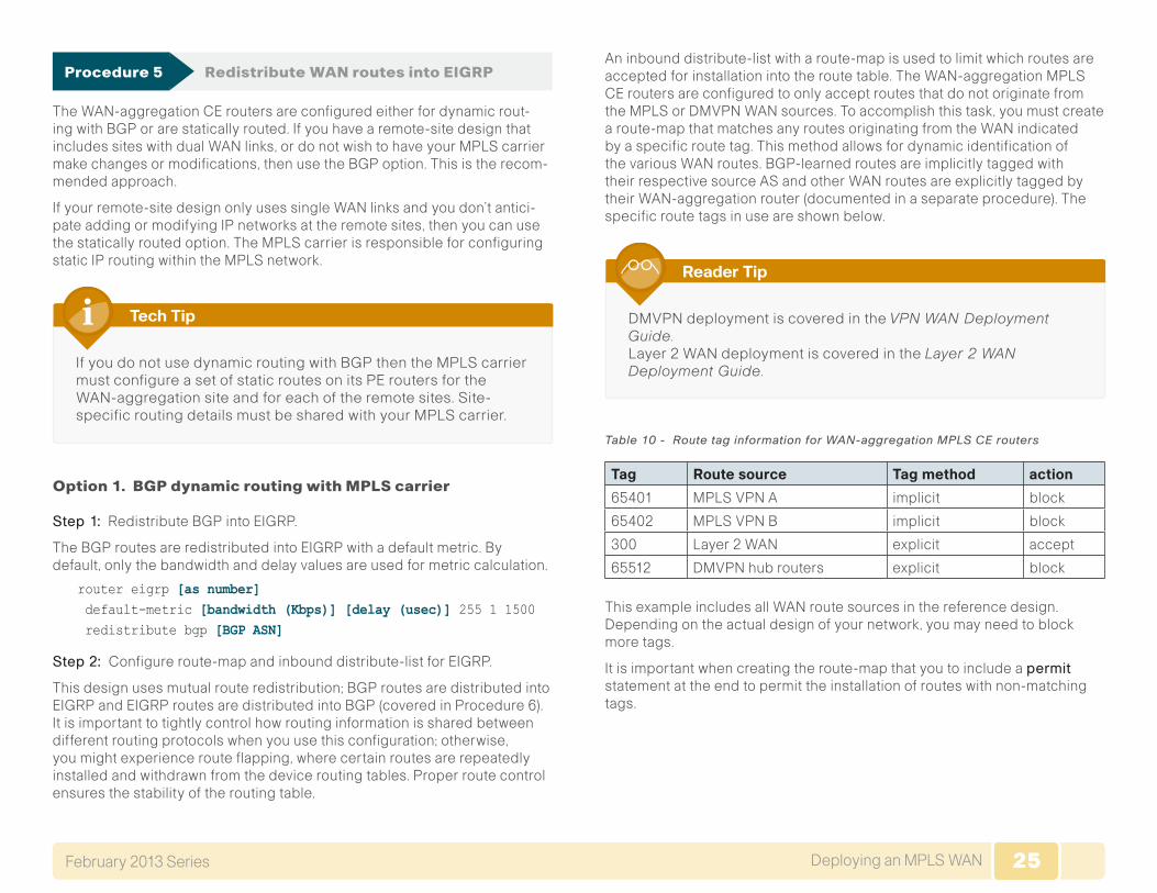
The WAN-aggregation CE routers are configured either for dynamic rout-ing with BGP or are statically routed. If you have a remote-site design that includes sites with dual WAN links, or do not wish to have your MPLS carrier make changes or modifications, then use the BGP option. This is the recom-mended approach.
If your remote-site design only uses single WAN links and you don’t antici-pate adding or modifying IP networks at the remote sites, then you can use the statically routed option. The MPLS carrier is responsible for configuring static IP routing within the MPLS network.
If you do not use dynamic routing with BGP then the MPLS carrier must configure a set of static routes on its PE routers for the WAN-aggregation site and for each of the remote sites. Site-specific routing details must be shared with your MPLS carrier.
Tech Tip
Option 1. BGP dynamic routing with MPLS carrier
Step 1: Redistribute BGP into EIGRP.
The BGP routes are redistributed into EIGRP with a default metric. By default, only the bandwidth and delay values are used for metric calculation.
router eigrp [as number] default-metric [bandwidth (Kbps)] [delay (usec)] 255 1 1500 redistribute bgp [BGP ASN]
Step 2: Configure route-map and inbound distribute-list for EIGRP.
This design uses mutual route redistribution; BGP routes are distributed into EIGRP and EIGRP routes are distributed into BGP (covered in Procedure 6). It is important to tightly control how routing information is shared between different routing protocols when you use this configuration; otherwise, you might experience route flapping, where certain routes are repeatedly installed and withdrawn from the device routing tables. Proper route control ensures the stability of the routing table.
An inbound distribute-list with a route-map is used to limit which routes are accepted for installation into the route table. The WAN-aggregation MPLS CE routers are configured to only accept routes that do not originate from the MPLS or DMVPN WAN sources. To accomplish this task, you must create a route-map that matches any routes originating from the WAN indicated by a specific route tag. This method allows for dynamic identification of the various WAN routes. BGP-learned routes are implicitly tagged with their respective source AS and other WAN routes are explicitly tagged by their WAN-aggregation router (documented in a separate procedure). The specific route tags in use are shown below.
DMVPN deployment is covered in the VPN WAN Deployment Guide. Layer 2 WAN deployment is covered in the Layer 2 WAN Deployment Guide.
Reader Tip
Table 10 - Route tag information for WAN-aggregation MPLS CE routers
Tag Route source Tag method action
65401 MPLS VPN A implicit block
65402 MPLS VPN B implicit block
300 Layer 2 WAN explicit accept
65512 DMVPN hub routers explicit block
This example includes all WAN route sources in the reference design. Depending on the actual design of your network, you may need to block more tags.
It is important when creating the route-map that you to include a permit statement at the end to permit the installation of routes with non-matching tags.

26Deploying an MPLS WANFebruary 2013 Series 26
If you configure mutual route redistribution without proper match-ing, tagging, and filtering, route-flapping may occur, which can cause instability.
Tech Tip
route-map BLOCK-TAGGED-ROUTES deny 10 match tag 65401 65402 65512!route-map BLOCK-TAGGED-ROUTES permit 20!router eigrp 100 distribute-list route-map BLOCK-TAGGED-ROUTES in default-metric 100000 100 255 1 1500 redistribute bgp 65511
Option 2. Static routing with service provider
Step 1: Configure static routes to remote sites’ LANs on the WAN-aggregation CE router. It is a best practice to summarize the remote-site network ranges into a single route when possible.
ip route 10.5.0.0 255.255.0.0 192.168.3.2
Step 2: It is desirable to advertise a route for the MPLS PE-CE links, which includes the CE routers’ WAN interfaces, so you can use this to determine router reachability for troubleshooting. It is a best practice to summarize the PE-CE link ranges into a single route when possible.
ip route 192.168.3.0 255.255.255.0 192.168.3.2
Step 3: You must also configure routes to the remote-site router loopback addresses. A single summary route for the loopback range may be used when possible.
ip route 10.255.251.0 255.255.255.0 192.168.3.2
Step 4: Configure EIGRP to advertise the remote-site static routes. These routes are redistributed into EIGRP with a default metric. By default, only the bandwidth and delay values are used for metric calculation.
router eigrp [as number] default-metric [bandwidth (Kbps)] [delay (usec)] 255 1 1500 redistribute static
Procedure 6 Configure BGP (recommended)
This procedure is only used when using BGP dynamic routing with the MPLS carrier.
Step 1: Enable BGP.
To complete this step, you must use a BGP ASN. You can consult with your MPLS carrier on the requirements for the ASN, but you may be permitted to use a private ASN as designated by IANA. The private ASN range is 64512 to 65534.
router bgp 65511 no synchronization bgp router-id 10.4.32.241 bgp log-neighbor-changes no auto-summary
Step 2: Configure eBGP.
You must configure BGP with the MPLS carrier PE device. The MPLS carrier must provide their ASN (the ASN in Step 1 is the ASN identifying your site). Because the carrier PE router uses a different ASN, this configuration is considered an external BGP (eBGP) connection.
The CE router only advertises network routes to the PE via BGP when:
• The route is specified in network statements and is present in the local routing table.
• The route is redistributed into BGP.
It is desirable to advertise a route for the PE-CE link, so you should include this network in a network statement. You can use this to determine router reachability for troubleshooting.
router bgp 65511 network 192.168.3.0 mask 255.255.255.252 neighbor 192.168.3.2 remote-as 65401
27Deploying an MPLS WANFebruary 2013 Series 27
Step 3: Redistribute EIGRP into BGP.
All EIGRP routes learned by the CE router, including routes from the core and for other WAN sites, should be advertised into the WAN. It is most efficient if you summarize these routes before they are advertised to the CE router.
Because BGP does not propagate a default route via redistribution, you must explicitly specify 0.0.0.0 in a network statement.
router bgp 65511 network 0.0.0.0 redistribute eigrp 100
Step 4: Configure iBGP (Optional).
With dual MPLS carriers, a BGP link is configured between the CE routers.
Since the CE routers are using the same ASN, this configuration is consid-ered an internal BGP (iBGP) connection. This design uses iBGP peering using device loopback addresses, which requires the update-source and next-hop-self-configuration options.
router bgp 65511 neighbor 10.4.32.242 remote-as 65511 neighbor 10.4.32.242 update-source Loopback0 neighbor 10.4.32.242 next-hop-self
Remote-Site MPLS CE Router Configuration
1. Configure the WAN Remote Router
2. Connect to the MPLS PE Router
3. Configure WAN Routing
4. Connect Router to Access Layer Switch
5. Configure Access Layer Routing
6. Configure Remote-Site DHCP
7. Configure Access Layer HSRP
8. Configure Transit Network
9. Configure EIGRP (LAN Side)
10. Configure BGP for Dual Router
11. Enable Enhanced Object Tracking
Process
Use this process for the configuration of any of the following:
• MPLS CE router for a MPLS WAN remote site (single router, single link).
• MPLS WAN Dual Carrier remote site. Use these procedures when performing the initial configuration of a dual-connected MPLS CE in the single-router, dual-link design or for configuring the first router of the dual-router, dual-link design.
The following flowchart provides details about the configuration process for a remote-site MPLS CE router.
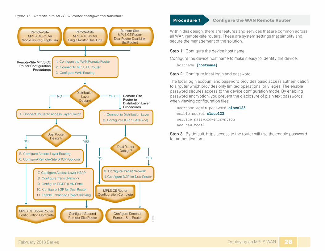
28Deploying an MPLS WANFebruary 2013 Series 28
Figure 15 - Remote-site MPLS CE router configuration flowchart
Distribution Layer
Design?YESNO
NO YES
YESNO
21
29
1. Configure the WAN Remote Router
2. Connect to MPLS PE Router
3. Configure WAN Routing
7. Configure Access Layer HSRP
8. Configure Transit Network
9. Configure EIGRP (LAN Side)
10. Configure BGP for Dual Router
11. Enable Enhanced Object Tracking
1. Connect to Distribution Layer
2. Configure EIGRP (LAN Side)
Remote-Site Router toDistribution LayerProcedures
Remote-Site MPLS CERouter Configuration
Procedures
4. Connect Router to Access Layer Switch
3. Configure Transit Network
4. Configure BGP for Dual Router
Dual RouterDesign?
Dual RouterDesign?
MPLS CE Spoke RouterConfiguration Complete Configure Second
Remote-Site RouterConfigure Second Remote-Site Router
MPLS CE RouterConfiguration Complete
Remote-Site MPLS CE Router
Dual Router, Dual Link (1st Router)
Remote-Site MPLS CE Router
Single Router, Dual Link
Remote-Site MPLS CE Router
Single Router, Single Link
5. Configure Access Layer Routing
6. Configure Remote-Site DHCP (Optional)
Procedure 1 Configure the WAN Remote Router
Within this design, there are features and services that are common across all WAN remote-site routers. These are system settings that simplify and secure the management of the solution.
Step 1: Configure the device host name.
Configure the device host name to make it easy to identify the device.
hostname [hostname]
Step 2: Configure local login and password.
The local login account and password provides basic access authentication to a router which provides only limited operational privileges. The enable password secures access to the device configuration mode. By enabling password encryption, you prevent the disclosure of plain text passwords when viewing configuration files.
username admin password c1sco123enable secret c1sco123service password-encryptionaaa new-model
Step 3: By default, https access to the router will use the enable password for authentication.
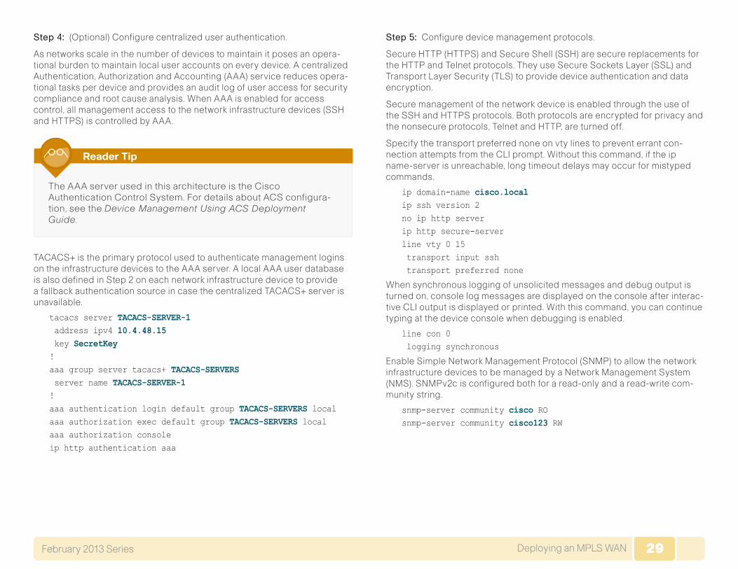
29Deploying an MPLS WANFebruary 2013 Series 29
Step 4: (Optional) Configure centralized user authentication.
As networks scale in the number of devices to maintain it poses an opera-tional burden to maintain local user accounts on every device. A centralized Authentication, Authorization and Accounting (AAA) service reduces opera-tional tasks per device and provides an audit log of user access for security compliance and root cause analysis. When AAA is enabled for access control, all management access to the network infrastructure devices (SSH and HTTPS) is controlled by AAA.
The AAA server used in this architecture is the Cisco Authentication Control System. For details about ACS configura-tion, see the Device Management Using ACS Deployment Guide.
Reader Tip
TACACS+ is the primary protocol used to authenticate management logins on the infrastructure devices to the AAA server. A local AAA user database is also defined in Step 2 on each network infrastructure device to provide a fallback authentication source in case the centralized TACACS+ server is unavailable.
tacacs server TACACS-SERVER-1 address ipv4 10.4.48.15 key SecretKey!aaa group server tacacs+ TACACS-SERVERS server name TACACS-SERVER-1!aaa authentication login default group TACACS-SERVERS localaaa authorization exec default group TACACS-SERVERS localaaa authorization consoleip http authentication aaa
Step 5: Configure device management protocols.
Secure HTTP (HTTPS) and Secure Shell (SSH) are secure replacements for the HTTP and Telnet protocols. They use Secure Sockets Layer (SSL) and Transport Layer Security (TLS) to provide device authentication and data encryption.
Secure management of the network device is enabled through the use of the SSH and HTTPS protocols. Both protocols are encrypted for privacy and the nonsecure protocols, Telnet and HTTP, are turned off.
Specify the transport preferred none on vty lines to prevent errant con-nection attempts from the CLI prompt. Without this command, if the ip name-server is unreachable, long timeout delays may occur for mistyped commands.
ip domain-name cisco.localip ssh version 2no ip http serverip http secure-serverline vty 0 15 transport input ssh transport preferred none
When synchronous logging of unsolicited messages and debug output is turned on, console log messages are displayed on the console after interac-tive CLI output is displayed or printed. With this command, you can continue typing at the device console when debugging is enabled.
line con 0 logging synchronous
Enable Simple Network Management Protocol (SNMP) to allow the network infrastructure devices to be managed by a Network Management System (NMS). SNMPv2c is configured both for a read-only and a read-write com-munity string.
snmp-server community cisco RO snmp-server community cisco123 RW
30Deploying an MPLS WANFebruary 2013 Series 30
Step 6: (Optional) In networks where network operational support is central-ized you can increase network security by using an access list to limit the networks that can access your device. In this example, only devices on the 10.4.48.0/24 network will be able to access the device via SSH or SNMP.
access-list 55 permit 10.4.48.0 0.0.0.255line vty 0 15 access-class 55 in !snmp-server community cisco RO 55 snmp-server community cisco123 RW 55
If you configure an access-list on the vty interface you may lose the ability to use ssh to login from one router to the next for hop-by-hop troubleshooting.
Tech Tip
Step 7: Configure a synchronized clock.
The Network Time Protocol (NTP) is designed to synchronize a network of devices. An NTP network usually gets its time from an authoritative time source, such as a radio clock or an atomic clock attached to a time server. NTP then distributes this time across the organizations network.
You should program network devices to synchronize to a local NTP server in the network. The local NTP server typically references a more accurate clock feed from an outside source. By configuring console messages, logs, and debug output to provide time stamps on output, you can cross-reference events in a network.
ntp server 10.4.48.17ntp update-calendar!clock timezone PST -8 clock summer-time PDT recurring !service timestamps debug datetime msec localtimeservice timestamps log datetime msec localtime
Step 8: Configure an in-band management interface.
The loopback interface is a logical interface that is always reachable as long as the device is powered on and any IP interface is reachable to the network. Because of this capability, the loopback address is the best way to manage the switch in-band. Layer 3 process and features are also bound to the loopback interface to ensure process resiliency.
The loopback address is commonly a host address with a 32-bit address mask. Allocate the loopback address from a unique network range that is not part of any other internal network summary range.
interface Loopback 0 ip address [ip address] 255.255.255.255 ip pim sparse-mode
The ippimsparse-mode command will be explained in the next step.
Bind the device processes for SNMP, SSH, PIM, TACACS+ and NTP to the loopback interface address for optimal resiliency:
snmp-server trap-source Loopback0ip ssh source-interface Loopback0ip pim register-source Loopback0ip tacacs source-interface Loopback0ntp source Loopback0
Step 9: Configure IP Multicast routing.
IP Multicast allows a single IP data stream to be replicated by the infra-structure (routers and switches) and sent from a single source to multiple receivers. Using IP Multicast is much more efficient than multiple individual unicast streams or a Broadcast stream that would propagate everywhere. IP Telephony MOH and IP Video Broadcast Streaming are two examples of IP Multicast applications.
To receive a particular IP Multicast data stream, end hosts must join a multicast group by sending an IGMP message to their local multicast router. In a traditional IP Multicast design, the local router consults another router in the network that is acting as an RP to map the receivers to active sources so they can join their streams.
In this design, which is based on sparse mode multicast operation, Auto RP is used to provide a simple yet scalable way to provide a highly resilient RP environment.
31Deploying an MPLS WANFebruary 2013 Series 31
Enable IP Multicast routing on the platforms in the global configuration mode.
ip multicast-routing
Every Layer 3 switch and router must be configured to discover the IP Multicast RP with autorp. Use the ippimautorplistener command to allow for discovery across sparse mode links. This configuration provides for future scaling and control of the IP Multicast environment and can change based on network needs and design.
ip pim autorp listener
All Layer 3 interfaces in the network must be enabled for sparse mode multicast operation.
ip pim sparse-mode
Procedure 2 Connect to the MPLS PE Router
Step 1: Assign the interface bandwidth.
The bandwidth value should correspond to the actual interface speed. Or, if you are using a subrate service, you should use the policed rate from the carrier.
The example shows a Gigabit interface (1000 Mbps) with a sub-rate of 10 Mbps.
interface [interface type] [number] bandwidth [bandwidth (kbps)]
Command Reference:
bandwidth kbps
10 Mbps = 10,000 kbps
Tech Tip
Step 2: Assign the IP address and netmask of the WAN interface.
The IP addressing used between CE and PE routers must be negotiated with your MPLS carrier. Typically a point-to-point netmask of 255.255.255.252 is used.
interface [interface type] [number] ip address [IP address] [netmask]
Step 3: Administratively enable the interface and disable CDP.
We do not recommend the use of CDP on external interfaces.
interface [interface type] [number] no cdp enable no shutdown
Example
interface GigabitEthernet0/0 bandwidth 10000 ip address 192.168.3.9 255.255.255.252 no cdp enable no shutdown
Procedure 3 Configure WAN Routing
The remote-site CE routers are configured either for dynamic routing with BGP or are statically routed. If you have a remote-site design that includes sites with dual WAN links or you do not want to have your MPLS carrier make changes or modifications, use the BGP option. This is the recommended approach, and assumes that the WAN-aggregation CE router has already been configured for BGP.
If your remote-site design only uses single WAN links and you don’t antici-pate adding or modifying IP networks at the remote site, then you can use the statically routed option. The MPLS carrier is responsible for configuring static IP routing within the MPLS network.
32Deploying an MPLS WANFebruary 2013 Series 32
If you do not use dynamic routing with BGP then the MPLS carrier must configure a set of static routes on its PE routers for the WAN-aggregation site and for each of the remote sites. Site specific routing details must be shared with your MPLS carrier.
Tech Tip
Option 1. BGP dynamic routing with MPLS carrier
Step 1: Enable BGP.
To complete this step, a BGP ASN is required. You might be able to reuse the same value used on the MPLS VPN CE from the WAN-aggregation site. Consult with your MPLS carrier on the requirements for the ASN.
router bgp 65511 no synchronization bgp router-id [IP address of Loopback0] bgp log-neighbor-changes no auto-summary
Step 2: Configure eBGP.
You must configure BGP with the MPLS carrier PE device. The MPLS carrier must provide their ASN (the ASN in Step 1 is the ASN identifying your site). Since the carrier PE router will use a different ASN, this configuration is considered an external BGP (eBGP) connection.
The CE router only advertises network routes to the PE via BGP in the follow-ing cases:
• The route is specified in network statements and is present in the local routing table.
• The route is redistributed into BGP (not applicable in the remote-site use case).
It is desirable to advertise a route for the PE-CE link, so you should include this network in a network statement. You can use this to determine router reachability for troubleshooting. Similarly, you must configure BGP to advertise the loopback network for the router.
You must advertise the remote-site LAN networks. The IP assignment for the remote sites was designed so that all of the networks in use can be summa-rized within a single aggregate route. The aggregate address as configured below suppresses the more specific routes. If any LAN network is present in the route table, the aggregate is advertised to the MPLS PE, which offers a measure of resiliency. If the various LAN networks cannot be summarized, you must list each individually. You must add a separate network statement for the loopback address.
router bgp 65511 network [PE-CE link network] mask [PE-CE link netmask] network [Loopback network] mask 255.255.255.255 network [DATA network] mask [netmask] network [VOICE network] mask [netmask] aggregate-address [summary IP address] [summary netmask] summary-only neighbor [IP address of PE] remote-as [carrier ASN]
Example
router bgp 65511 no synchronization bgp router-id 10.255.251.206 bgp log-neighbor-changes network 192.168.3.8 mask 255.255.255.252 network 10.255.251.206 mask 255.255.255.255 network 10.5.12.0 mask 255.255.255.0 network 10.5.13.0 mask 255.255.255.0 aggregate-address 10.5.8.0 255.255.248.0 summary-only neighbor 192.168.3.10 remote-as 65401 no auto-summary
Option 2. Static routing with service provider
Step 1: This option has remote sites using static routing to the MPLS WAN to forward all traffic to the WAN-aggregation site. Only a default route is required.
ip route 0.0.0.0 0.0.0.0 192.168.3.10
33Deploying an MPLS WANFebruary 2013 Series 33
Step 2: Both the remote-site specific IP range and the chosen loopback IP address for the router must be provided to the MPLS carrier for each remote site, so that they can properly configure the static routes to the remote-site.
For each remote site with static routing, the WAN-aggregation CE router must have a corresponding static host route for that site’s loopback address.
Tech Tip
Procedure 4 Connect Router to Access Layer Switch
Please refer to the LAN Deployment Guide for complete access layer configuration details. This guide only includes the additional steps to complete the distribution layer configuration.
If you are using a remote-site distribution layer then skip to the “Deploying a WAN Remote-Site Distribution Layer” section of this guide.
Reader Tip
Layer 2 EtherChannels are used to interconnect the CE router to the access layer in the most resilient method possible. If your access layer device is a single fixed configuration switch a simple Layer 2 trunk between the router and switch is used.
In the access layer design, the remote sites use collapsed routing, with 802.1Q trunk interfaces to the LAN access layer. The VLAN numbering is locally significant only.
Option 1. Layer 2 EtherChannel from router to access layer switch
Step 1: Configure port-channel interface on the router.
interface Port-channel1 description EtherChannel link to RS206-A2960S no shutdown
Step 2: Configure EtherChannel member interfaces on the router.
Configure the physical interfaces to tie to the logical port-channel using the channel-group command. The number for the port-channel and channel-group must match. Not all router platforms can support LACP to negotiate with the switch, so EtherChannel is configured statically.
interface GigabitEthernet0/1 description RS206-A2960S Gig1/0/24!interface GigabitEthernet0/2 description RS206-A2960S Gig2/0/24!interface range GigabitEthernet0/1, GigabitEthernet0/2 no ip address channel-group 1 no shutdown
Step 3: Configure EtherChannel member interfaces on the access layer switch.
Connect the routerEtherChannel uplinks to separate switches in the access layer switch stack, or in the case of the Cisco Catalyst 4507R+E distribution layer, to separate redundant modules for additional resiliency.
The physical interfaces that are members of a Layer 2 EtherChannel are configured prior to configuring the logical port-channel interface. Doing the configuration in this order allows for minimal configuration and reduces errors because most of the commands entered to a port-channel interface are copied to its members interfaces and do not require manual replication.
Configure two physical interfaces to be members of the EtherChannel. Also, apply the egress QoS macro that was defined in the LAN switch platform configuration procedure to ensure traffic is prioritized appropriately.
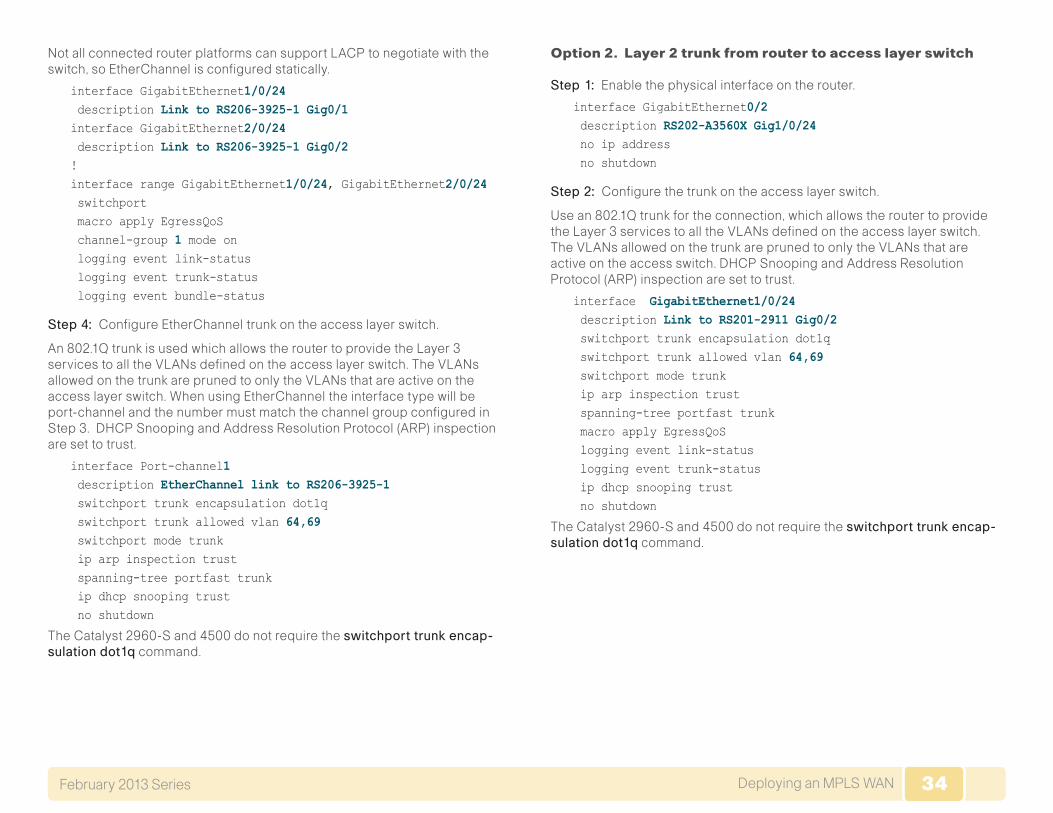
34Deploying an MPLS WANFebruary 2013 Series 34
Not all connected router platforms can support LACP to negotiate with the switch, so EtherChannel is configured statically.
interface GigabitEthernet1/0/24 description Link to RS206-3925-1 Gig0/1interface GigabitEthernet2/0/24 description Link to RS206-3925-1 Gig0/2!interface range GigabitEthernet1/0/24, GigabitEthernet2/0/24 switchport macro apply EgressQoS channel-group 1 mode on logging event link-status logging event trunk-status logging event bundle-status
Step 4: Configure EtherChannel trunk on the access layer switch.
An 802.1Q trunk is used which allows the router to provide the Layer 3 services to all the VLANs defined on theaccess layer switch. The VLANs allowed on the trunk are pruned to only the VLANs that are active on the access layer switch. When using EtherChannel the interface type will be port-channel and the number must match the channel group configured in Step 3. DHCP Snooping and Address Resolution Protocol (ARP) inspection are set to trust.
interface Port-channel1 description EtherChannel link to RS206-3925-1 switchport trunk encapsulation dot1q switchport trunk allowed vlan 64,69 switchport mode trunk ip arp inspection trust spanning-tree portfast trunk ip dhcp snooping trust no shutdown
The Catalyst 2960-S and 4500 do not require the switchporttrunkencap-sulationdot1q command.
Option 2. Layer 2 trunk from router to access layer switch
Step 1: Enable the physical interface on the router.
interface GigabitEthernet0/2 description RS202-A3560X Gig1/0/24 no ip address no shutdown
Step 2: Configure the trunk on the access layer switch.
Use an 802.1Q trunk for the connection, which allows the router to provide the Layer 3 services to all the VLANs defined on the access layer switch. The VLANs allowed on the trunk are pruned to only the VLANs that are active on the access switch. DHCP Snooping and Address Resolution Protocol (ARP) inspection are set to trust.
interface GigabitEthernet1/0/24 description Link to RS201-2911 Gig0/2 switchport trunk encapsulation dot1q switchport trunk allowed vlan 64,69 switchport mode trunk ip arp inspection trust spanning-tree portfast trunk macro apply EgressQoS logging event link-status logging event trunk-status ip dhcp snooping trust no shutdown
The Catalyst 2960-S and 4500 do not require the switchporttrunkencap-sulationdot1q command.
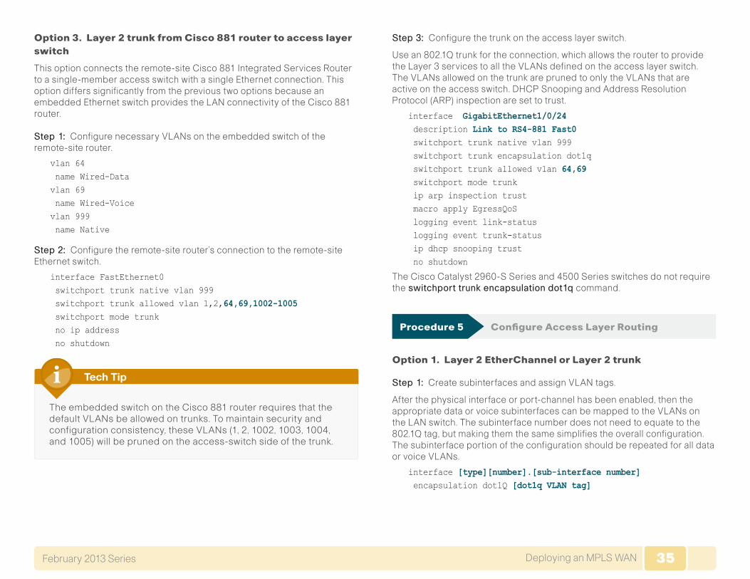
35Deploying an MPLS WANFebruary 2013 Series 35
Option 3. Layer 2 trunk from Cisco 881 router to access layer switch
This option connects the remote-site Cisco 881 Integrated Services Router to a single-member access switch with a single Ethernet connection. This option differs significantly from the previous two options because an embedded Ethernet switch provides the LAN connectivity of the Cisco 881 router.
Step 1: Configure necessary VLANs on the embedded switch of the remote-site router.
vlan 64 name Wired-Datavlan 69 name Wired-Voicevlan 999 name Native
Step 2: Configure the remote-site router’s connection to the remote-site Ethernet switch.
interface FastEthernet0 switchport trunk native vlan 999 switchport trunk allowed vlan 1,2,64,69,1002-1005 switchport mode trunk no ip address no shutdown
The embedded switch on the Cisco 881 router requires that the default VLANs be allowed on trunks. To maintain security and configuration consistency, these VLANs (1, 2, 1002, 1003, 1004, and 1005) will be pruned on the access-switch side of the trunk.
Tech Tip
Step 3: Configure the trunk on the access layer switch.
Use an 802.1Q trunk for the connection, which allows the router to provide the Layer 3 services to all the VLANs defined on the access layer switch. The VLANs allowed on the trunk are pruned to only the VLANs that are active on the access switch. DHCP Snooping and Address Resolution Protocol (ARP) inspection are set to trust.
interface GigabitEthernet1/0/24 description Link to RS4-881 Fast0 switchport trunk native vlan 999 switchport trunk encapsulation dot1q switchport trunk allowed vlan 64,69 switchport mode trunk ip arp inspection trust macro apply EgressQoS logging event link-status logging event trunk-status ip dhcp snooping trust no shutdown
The Cisco Catalyst 2960-S Series and 4500 Series switches do not require theswitchporttrunkencapsulationdot1qcommand.
Procedure 5 Configure Access Layer Routing
Option 1. Layer 2 EtherChannel or Layer 2 trunk
Step 1: Create subinterfaces and assign VLAN tags.
After the physical interface or port-channel has been enabled, then the appropriate data or voice subinterfaces can be mapped to the VLANs on the LAN switch. The subinterface number does not need to equate to the 802.1Q tag, but making them the same simplifies the overall configuration. The subinterface portion of the configuration should be repeated for all data or voice VLANs.
interface [type][number].[sub-interface number] encapsulation dot1Q [dot1q VLAN tag]
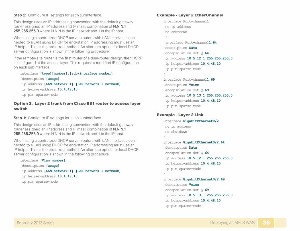
36Deploying an MPLS WANFebruary 2013 Series 36
Step 2: Configure IP settings for each subinterface.
This design uses an IP addressing convention with the default gateway router assigned an IP address and IP mask combination of N.N.N.1255.255.255.0 where N.N.N is the IP network and 1 is the IP host.
When using a centralized DHCP server, routers with LAN interfaces con-nected to a LAN using DHCP for end-station IP addressing must use an IP helper. This is the preferred method. An alternate option for local DHCP server configuration is shown in the following procedure.
If the remote-site router is the first router of a dual-router design, then HSRP is configured at the access layer. This requires a modified IP configuration on each subinterface.
interface [type][number].[sub-interface number] description [usage] ip address [LAN network 1] [LAN network 1 netmask] ip helper-address 10.4.48.10 ip pim sparse-mode
Option 2. Layer 2 trunk from Cisco 881 router to access layer switch
Step 1: Configure IP settings for each subinterface.
This design uses an IP addressing convention with the default gateway router assigned an IP address and IP mask combination of N.N.N.1255.255.255.0 where N.N.N is the IP network and 1 is the IP host.
When using a centralized DHCP server, routers with LAN interfaces con-nected to a LAN using DHCP for end-station IP addressing must use an IP helper. This is the preferred method. An alternate option for local DHCP server configuration is shown in the following procedure.
interface [Vlan number] description [usage] ip address [LAN network 1] [LAN network 1 netmask] ip helper-address 10.4.48.10 ip pim sparse-mode
Example - Layer 2 EtherChannel
interface Port-channel1 no ip address no shutdown ! interface Port-channel1.64 description Data encapsulation dot1Q 64 ip address 10.5.12.1 255.255.255.0 ip helper-address 10.4.48.10 ip pim sparse-mode!interface Port-channel1.69 description Voice encapsulation dot1Q 69 ip address 10.5.13.1 255.255.255.0 ip helper-address 10.4.48.10 ip pim sparse-mode
Example - Layer 2 Link
interface GigabitEthernet0/2 no ip address no shutdown!interface GigabitEthernet0/2.64 description Data encapsulation dot1Q 64 ip address 10.5.12.1 255.255.255.0 ip helper-address 10.4.48.10 ip pim sparse-mode!interface GigabitEthernet0/2.69 description Voice encapsulation dot1Q 69 ip address 10.5.13.1 255.255.255.0 ip helper-address 10.4.48.10 ip pim sparse-mode
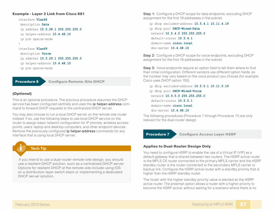
37Deploying an MPLS WANFebruary 2013 Series 37
Example - Layer 2 Link from Cisco 881
interface Vlan64 description Data ip address 10.5.28.1 255.255.255.0 ip helper-address 10.4.48.10 ip pim sparse-mode !interface Vlan69 description Voice ip address 10.5.29.1 255.255.255.0 ip helper-address 10.4.48.10 ip pim sparse-mode
Procedure 6 Configure Remote-Site DHCP
(Optional)
This is an optional procedure. The previous procedure assumes the DHCP service has been configured centrally and uses theiphelper-address com-mand to forward DHCP requests to the centralized DHCP server.
You may also choose to run a local DHCP server on the remote-site router instead. If so, use the following steps to use local DHCP service on the router to assign basic network configuration for IP phones, wireless access-points, users’ laptop and desktop computers, and other endpoint devices. Remove the previously configurediphelper-address commands for any interface that is using local DHCP server.
If you intend to use a dual-router remote-site design, you should use a resilient DHCP solution, such as a centralized DHCP server. Options for resilient DHCP at the remote-site include using IOS on a distribution-layer switch stack or implementing a dedicated DHCP server solution.
Tech Tip
Step 1: Configure a DHCP scope for data endpoints, excluding DHCP assignment for the first 19 addresses in the subnet.
ip dhcp excluded-address 10.5.4.1 10.11.4.19 ip dhcp pool DHCP-Wired-Data network 10.5.4.0 255.255.255.0 default-router 10.5.4.1 domain-name cisco.local dns-server 10.4.48.10
Step 2: Configure a DHCP scope for voice endpoints, excluding DHCP assignment for the first 19 addresses in the subnet.
Step 3: Voice endpoints require an option field to tell them where to find their initial configuration. Different vendors use different option fields, so the number may vary based on the voice product you choose (for example, Cisco uses DHCP option 150).
ip dhcp excluded-address 10.5.5.1 10.11.5.19 ip dhcp pool DHCP-Wired-Voice network 10.5.5.0 255.255.255.0 default-router 10.5.5.1 domain-name cisco.local dns-server 10.4.48.10
The following procedures (Procedure 7 through Procedure 11) are only relevant for the dual-router design.
Procedure 7 Configure Access Layer HSRP
Applies to Dual-Router Design Only
You need to configure HSRP to enable the use of a Virtual IP (VIP) as a default gateway that is shared between two routers. The HSRP active router is the MPLS CE router connected to the primary MPLS carrier and the HSRP standby router is the router connected to the secondary MPLS carrier or backup link. Configure the HSRP active router with a standby priority that is higher than the HSRP standby router.
The router with the higher standby priority value is elected as the HSRP active router. The preempt option allows a router with a higher priority to become the HSRP active, without waiting for a scenario where there is no
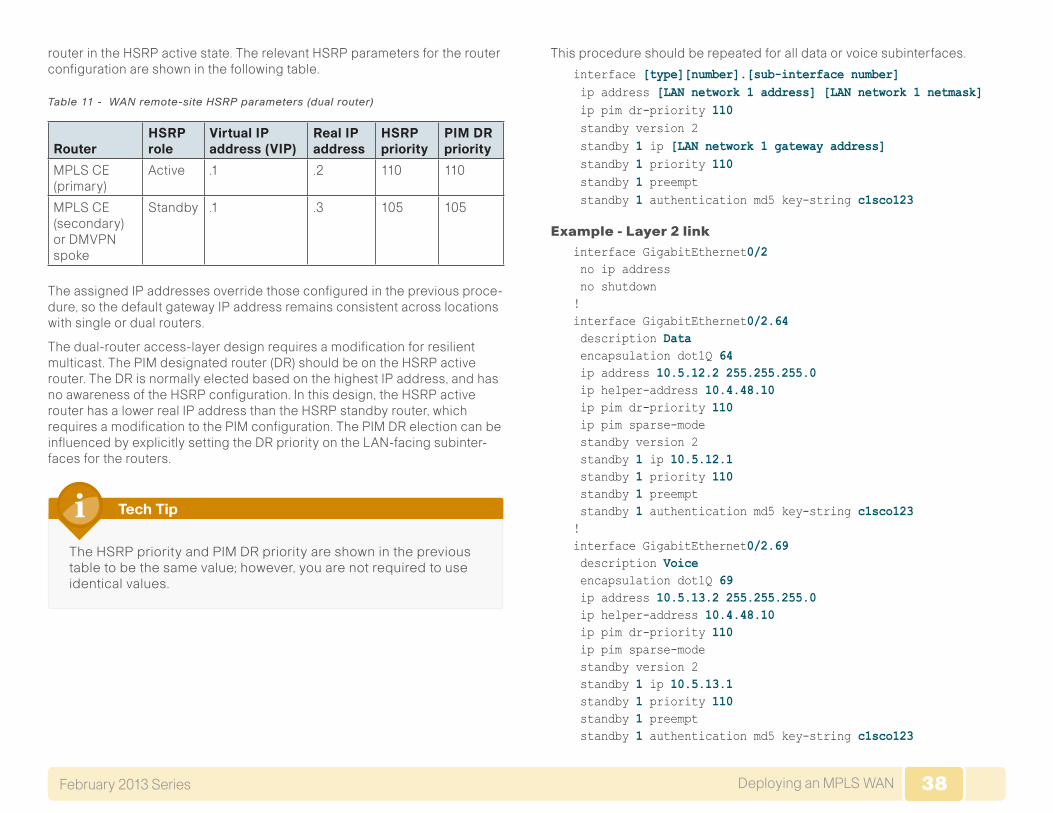
38Deploying an MPLS WANFebruary 2013 Series 38
router in the HSRP active state. The relevant HSRP parameters for the router configuration are shown in the following table.
Table 11 - WAN remote-site HSRP parameters (dual router)
Router HSRP role
Virtual IP address (VIP)
Real IP address
HSRP priority
PIM DR priority
MPLS CE (primary)
Active .1 .2 110 110
MPLS CE (secondary) or DMVPN spoke
Standby .1 .3 105 105
The assigned IP addresses override those configured in the previous proce-dure, so the default gateway IP address remains consistent across locations with single or dual routers.
The dual-router access-layer design requires a modification for resilient multicast. The PIM designated router (DR) should be on the HSRP active router. The DR is normally elected based on the highest IP address, and has no awareness of the HSRP configuration. In this design, the HSRP active router has a lower real IP address than the HSRP standby router, which requires a modification to the PIM configuration. The PIM DR election can be influenced by explicitly setting the DR priority on the LAN-facing subinter-faces for the routers.
The HSRP priority and PIM DR priority are shown in the previous table to be the same value; however, you are not required to use identical values.
Tech Tip
This procedure should be repeated for all data or voice subinterfaces.
interface [type][number].[sub-interface number] ip address [LAN network 1 address] [LAN network 1 netmask] ip pim dr-priority 110 standby version 2 standby 1 ip [LAN network 1 gateway address] standby 1 priority 110 standby 1 preempt standby 1 authentication md5 key-string c1sco123
Example - Layer 2 linkinterface GigabitEthernet0/2 no ip address no shutdown!interface GigabitEthernet0/2.64 description Data encapsulation dot1Q 64 ip address 10.5.12.2 255.255.255.0 ip helper-address 10.4.48.10 ip pim dr-priority 110 ip pim sparse-mode standby version 2 standby 1 ip 10.5.12.1 standby 1 priority 110 standby 1 preempt standby 1 authentication md5 key-string c1sco123!interface GigabitEthernet0/2.69 description Voice encapsulation dot1Q 69 ip address 10.5.13.2 255.255.255.0 ip helper-address 10.4.48.10 ip pim dr-priority 110 ip pim sparse-mode standby version 2 standby 1 ip 10.5.13.1 standby 1 priority 110 standby 1 preempt standby 1 authentication md5 key-string c1sco123
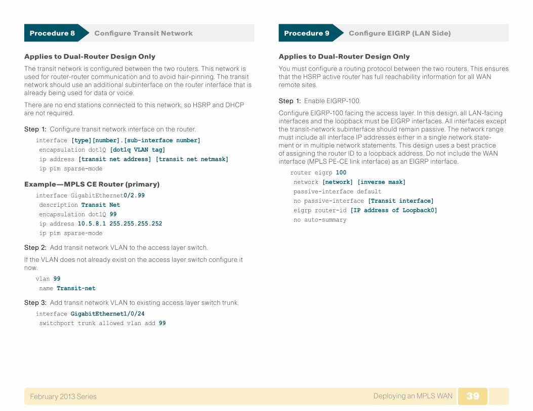
39Deploying an MPLS WANFebruary 2013 Series 39
Procedure 8 Configure Transit Network
Applies to Dual-Router Design Only
The transit network is configured between the two routers. This network is used for router-router communication and to avoid hair-pinning. The transit network should use an additional subinterface on the router interface that is already being used for data or voice.
There are no end stations connected to this network, so HSRP and DHCP are not required.
Step 1: Configure transit network interface on the router.
interface [type][number].[sub-interface number] encapsulation dot1Q [dot1q VLAN tag] ip address [transit net address] [transit net netmask] ip pim sparse-mode
Example—MPLS CE Router (primary)
interface GigabitEthernet0/2.99 description Transit Net encapsulation dot1Q 99 ip address 10.5.8.1 255.255.255.252 ip pim sparse-mode
Step 2: Add transit network VLAN to the access layer switch.
If the VLAN does not already exist on the access layer switch configure it now.
vlan 99 name Transit-net
Step 3: Add transit network VLAN to existing access layer switch trunk.
interface GigabitEthernet1/0/24 switchport trunk allowed vlan add 99
Procedure 9 Configure EIGRP (LAN Side)
Applies to Dual-Router Design Only
You must configure a routing protocol between the two routers. This ensures that the HSRP active router has full reachability information for all WAN remote sites.
Step 1: Enable EIGRP-100.
Configure EIGRP-100 facing the access layer. In this design, all LAN-facing interfaces and the loopback must be EIGRP interfaces. All interfaces except the transit-network subinterface should remain passive. The network range must include all interface IP addresses either in a single network state-ment or in multiple network statements. This design uses a best practice of assigning the router ID to a loopback address. Do not include the WAN interface (MPLS PE-CE link interface) as an EIGRP interface.
router eigrp 100 network [network] [inverse mask] passive-interface default no passive-interface [Transit interface] eigrp router-id [IP address of Loopback0] no auto-summary
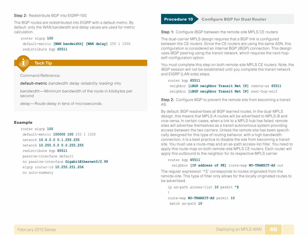
40Deploying an MPLS WANFebruary 2013 Series 40
Step 2: Redistribute BGP into EIGRP-100.
The BGP routes are redistributed into EIGRP with a default metric. By default, only the WAN bandwidth and delay values are used for metric calculation.
router eigrp 100 default-metric [WAN bandwidth] [WAN delay] 255 1 1500 redistribute bgp 65511
Command Reference:
default-metric bandwidth delay reliability loading mtu
bandwidth—Minimum bandwidth of the route in kilobytes per second
delay—Route delay in tens of microseconds.
Tech Tip
Example
router eigrp 100 default-metric 100000 100 255 1 1500 network 10.4.0.0 0.1.255.255 network 10.255.0.0 0.0.255.255 redistribute bgp 65511 passive-interface default no passive-interface GigabitEthernet0/2.99 eigrp router-id 10.255.251.206 no auto-summary
Procedure 10 Configure BGP for Dual Router
Step 1: Configure iBGP between the remote-site MPLS CE routers.
The dual-carrier MPLS design requires that a BGP link is configured between the CE routers. Since the CE routers are using the same ASN, this configuration is considered an internal BGP (iBGP) connection. This design uses iBGP peering using the transit network, which requires the next-hop-self-configuration option.
You must complete this step on both remote-site MPLS CE routers. Note, the iBGP session will not be established until you complete the transit network and EIGRP (LAN side) steps.
router bgp 65511 neighbor [iBGP neighbor Transit Net IP] remote-as 65511 neighbor [iBGP neighbor Transit Net IP] next-hop-self
Step 2: Configure BGP to prevent the remote site from becoming a transit AS.
By default, BGP readvertises all BGP learned routes. In the dual-MPLS design, this means that MPLS-A routes will be advertised to MPLS-B and vice-versa. In certain cases, when a link to a MPLS hub has failed, remote sites will advertise themselves as a transit autonomous system providing access between the two carriers. Unless the remote site has been specifi-cally designed for this type of routing behavior, with a high bandwidth connection, it is a best practice to disable the site from becoming a transit site. You must use a route-map and an as-path access-list filter. You need to apply this route-map on both remote-site MPLS CE routers. Each router will apply this outbound to the neighbor for its respective MPLS carrier.
router bgp 65511 neighbor [IP address of PE] route-map NO-TRANSIT-AS out
The regular expression “^$” corresponds to routes originated from the remote-site. This type of filter only allows for the locally originated routes to be advertised.
ip as-path access-list 10 permit ^$!route-map NO-TRANSIT-AS permit 10 match as-path 10
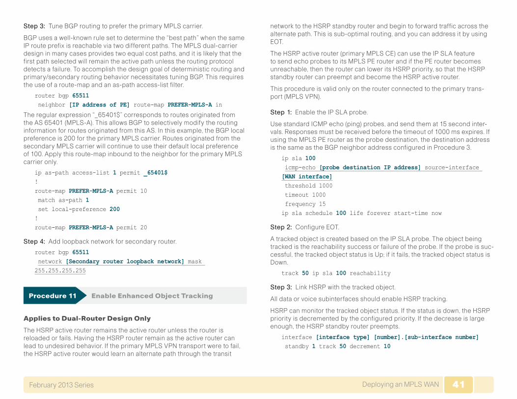
41Deploying an MPLS WANFebruary 2013 Series 41
Step 3: Tune BGP routing to prefer the primary MPLS carrier.
BGP uses a well-known rule set to determine the “best path” when the same IP route prefix is reachable via two different paths. The MPLS dual-carrier design in many cases provides two equal cost paths, and it is likely that the first path selected will remain the active path unless the routing protocol detects a failure. To accomplish the design goal of deterministic routing and primary/secondary routing behavior necessitates tuning BGP. This requires the use of a route-map and an as-path access-list filter.
router bgp 65511 neighbor [IP address of PE] route-map PREFER-MPLS-A in
The regular expression “_65401$” corresponds to routes originated from the AS 65401 (MPLS-A). This allows BGP to selectively modify the routing information for routes originated from this AS. In this example, the BGP local preference is 200 for the primary MPLS carrier. Routes originated from the secondary MPLS carrier will continue to use their default local preference of 100. Apply this route-map inbound to the neighbor for the primary MPLS carrier only.
ip as-path access-list 1 permit _65401$!route-map PREFER-MPLS-A permit 10 match as-path 1 set local-preference 200!route-map PREFER-MPLS-A permit 20
Step 4: Add loopback network for secondary router.
router bgp 65511 network [Secondary router loopback network] mask 255.255.255.255
Procedure 11 Enable Enhanced Object Tracking
Applies to Dual-Router Design Only
The HSRP active router remains the active router unless the router is reloaded or fails. Having the HSRP router remain as the active router can lead to undesired behavior. If the primary MPLS VPN transport were to fail, the HSRP active router would learn an alternate path through the transit
network to the HSRP standby router and begin to forward traffic across the alternate path. This is sub-optimal routing, and you can address it by using EOT.
The HSRP active router (primary MPLS CE) can use the IP SLA feature to send echo probes to its MPLS PE router and if the PE router becomes unreachable, then the router can lower its HSRP priority, so that the HSRP standby router can preempt and become the HSRP active router.
This procedure is valid only on the router connected to the primary trans-port (MPLS VPN).
Step 1: Enable the IP SLA probe.
Use standard ICMP echo (ping) probes, and send them at 15 second inter-vals. Responses must be received before the timeout of 1000 ms expires. If using the MPLS PE router as the probe destination, the destination address is the same as the BGP neighbor address configured in Procedure 3.
ip sla 100 icmp-echo [probe destination IP address] source-interface [WAN interface] threshold 1000 timeout 1000 frequency 15ip sla schedule 100 life forever start-time now
Step 2: Configure EOT.
A tracked object is created based on the IP SLA probe. The object being tracked is the reachability success or failure of the probe. If the probe is suc-cessful, the tracked object status is Up; if it fails, the tracked object status is Down.
track 50 ip sla 100 reachability
Step 3: Link HSRP with the tracked object.
All data or voice subinterfaces should enable HSRP tracking.
HSRP can monitor the tracked object status. If the status is down, the HSRP priority is decremented by the configured priority. If the decrease is large enough, the HSRP standby router preempts.
interface [interface type] [number].[sub-interface number] standby 1 track 50 decrement 10
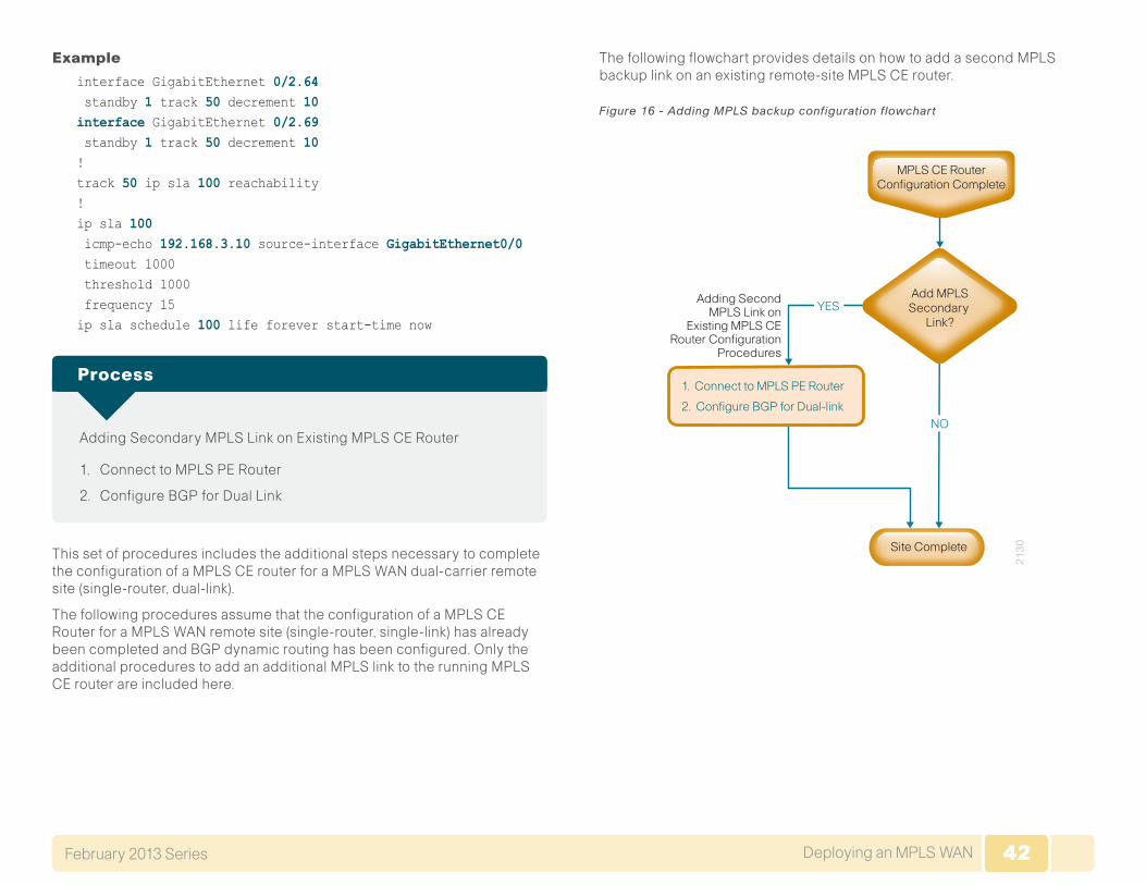
42Deploying an MPLS WANFebruary 2013 Series 42
Example
interface GigabitEthernet 0/2.64 standby 1 track 50 decrement 10interface GigabitEthernet 0/2.69 standby 1 track 50 decrement 10!track 50 ip sla 100 reachability!ip sla 100 icmp-echo 192.168.3.10 source-interface GigabitEthernet0/0 timeout 1000 threshold 1000 frequency 15ip sla schedule 100 life forever start-time now
Adding Secondary MPLS Link on Existing MPLS CE Router
1. Connect to MPLS PE Router
2. Configure BGP for Dual Link
Process
This set of procedures includes the additional steps necessary to complete the configuration of a MPLS CE router for a MPLS WAN dual-carrier remote site (single-router, dual-link).
The following procedures assume that the configuration of a MPLS CE Router for a MPLS WAN remote site (single-router, single-link) has already been completed and BGP dynamic routing has been configured. Only the additional procedures to add an additional MPLS link to the running MPLS CE router are included here.
The following flowchart provides details on how to add a second MPLS backup link on an existing remote-site MPLS CE router.
Figure 16 - Adding MPLS backup configuration flowchart
1. Connect to MPLS PE Router
2. Configure BGP for Dual-link
21
30
NO
YESAdding Second
MPLS Link onExisting MPLS CE
Router ConfigurationProcedures
Site Complete
MPLS CE RouterConfiguration Complete
Add MPLSSecondary
Link?
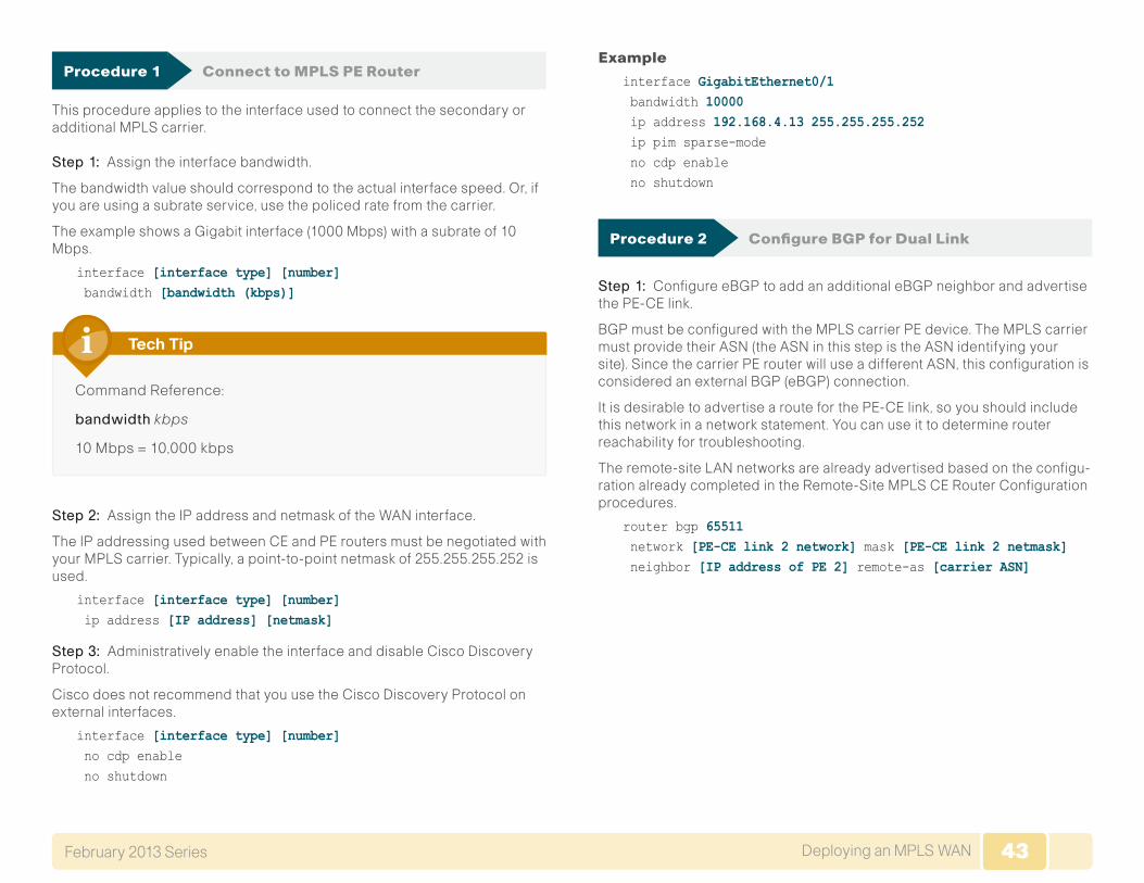
43Deploying an MPLS WANFebruary 2013 Series 43
Procedure 1 Connect to MPLS PE Router
This procedure applies to the interface used to connect the secondary or additional MPLS carrier.
Step 1: Assign the interface bandwidth.
The bandwidth value should correspond to the actual interface speed. Or, if you are using a subrate service, use the policed rate from the carrier.
The example shows a Gigabit interface (1000 Mbps) with a subrate of 10 Mbps.
interface [interface type] [number] bandwidth [bandwidth (kbps)]
Command Reference:
bandwidth kbps
10 Mbps = 10,000 kbps
Tech Tip
Step 2: Assign the IP address and netmask of the WAN interface.
The IP addressing used between CE and PE routers must be negotiated with your MPLS carrier. Typically, a point-to-point netmask of 255.255.255.252 is used.
interface [interface type] [number] ip address [IP address] [netmask]
Step 3: Administratively enable the interface and disable Cisco Discovery Protocol.
Cisco does not recommend that you use the Cisco Discovery Protocol on external interfaces.
interface [interface type] [number] no cdp enable no shutdown
Example
interface GigabitEthernet0/1 bandwidth 10000 ip address 192.168.4.13 255.255.255.252 ip pim sparse-mode no cdp enable no shutdown
Procedure 2 Configure BGP for Dual Link
Step 1: Configure eBGP to add an additional eBGP neighbor and advertise the PE-CE link.
BGP must be configured with the MPLS carrier PE device. The MPLS carrier must provide their ASN (the ASN in this step is the ASN identifying your site). Since the carrier PE router will use a different ASN, this configuration is considered an external BGP (eBGP) connection.
It is desirable to advertise a route for the PE-CE link, so you should include this network in a network statement. You can use it to determine router reachability for troubleshooting.
The remote-site LAN networks are already advertised based on the configu-ration already completed in the Remote-Site MPLS CE Router Configuration procedures.
router bgp 65511 network [PE-CE link 2 network] mask [PE-CE link 2 netmask] neighbor [IP address of PE 2] remote-as [carrier ASN]
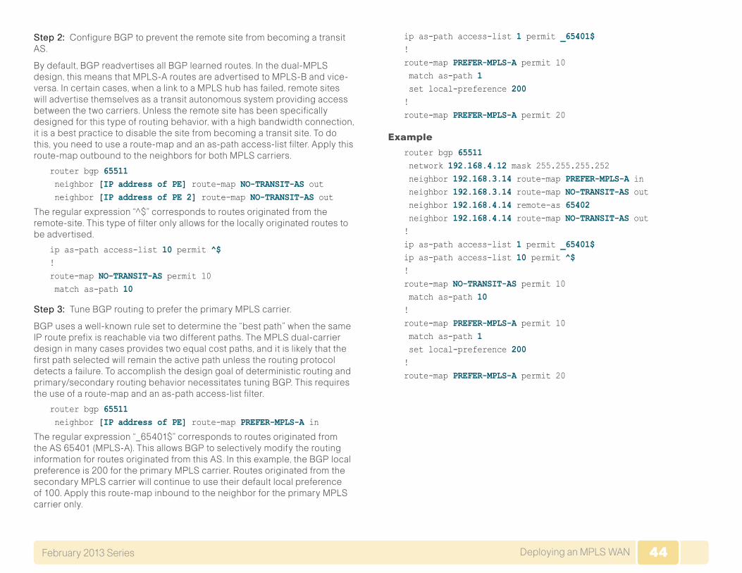
44Deploying an MPLS WANFebruary 2013 Series 44
Step 2: Configure BGP to prevent the remote site from becoming a transit AS.
By default, BGP readvertises all BGP learned routes. In the dual-MPLS design, this means that MPLS-A routes are advertised to MPLS-B and vice-versa. In certain cases, when a link to a MPLS hub has failed, remote sites will advertise themselves as a transit autonomous system providing access between the two carriers. Unless the remote site has been specifically designed for this type of routing behavior, with a high bandwidth connection, it is a best practice to disable the site from becoming a transit site. To do this, you need to use a route-map and an as-path access-list filter. Apply this route-map outbound to the neighbors for both MPLS carriers.
router bgp 65511 neighbor [IP address of PE] route-map NO-TRANSIT-AS out neighbor [IP address of PE 2] route-map NO-TRANSIT-AS out
The regular expression “^$” corresponds to routes originated from the remote-site. This type of filter only allows for the locally originated routes to be advertised.
ip as-path access-list 10 permit ^$!route-map NO-TRANSIT-AS permit 10 match as-path 10
Step 3: Tune BGP routing to prefer the primary MPLS carrier.
BGP uses a well-known rule set to determine the “best path” when the same IP route prefix is reachable via two different paths. The MPLS dual-carrier design in many cases provides two equal cost paths, and it is likely that the first path selected will remain the active path unless the routing protocol detects a failure. To accomplish the design goal of deterministic routing and primary/secondary routing behavior necessitates tuning BGP. This requires the use of a route-map and an as-path access-list filter.
router bgp 65511 neighbor [IP address of PE] route-map PREFER-MPLS-A in
The regular expression “_65401$” corresponds to routes originated from the AS 65401 (MPLS-A). This allows BGP to selectively modify the routing information for routes originated from this AS. In this example, the BGP local preference is 200 for the primary MPLS carrier. Routes originated from the secondary MPLS carrier will continue to use their default local preference of 100. Apply this route-map inbound to the neighbor for the primary MPLS carrier only.
ip as-path access-list 1 permit _65401$!route-map PREFER-MPLS-A permit 10 match as-path 1 set local-preference 200!route-map PREFER-MPLS-A permit 20
Example
router bgp 65511 network 192.168.4.12 mask 255.255.255.252 neighbor 192.168.3.14 route-map PREFER-MPLS-A in neighbor 192.168.3.14 route-map NO-TRANSIT-AS out neighbor 192.168.4.14 remote-as 65402 neighbor 192.168.4.14 route-map NO-TRANSIT-AS out! ip as-path access-list 1 permit _65401$ip as-path access-list 10 permit ^$!route-map NO-TRANSIT-AS permit 10 match as-path 10!route-map PREFER-MPLS-A permit 10 match as-path 1 set local-preference 200!route-map PREFER-MPLS-A permit 20
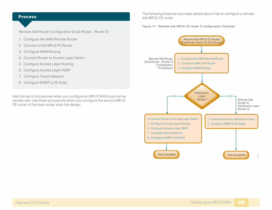
45Deploying an MPLS WANFebruary 2013 Series 45
Remote-Site Router Configuration (Dual-Router - Router 2)
1. Configure the WAN Remote Router
2. Connect to the MPLS PE Router
3. Configure WAN Routing
4. Connect Router to Access Layer Switch
5. Configure Access Layer Routing
6. Configure Access Layer HSRP
7. Configure Transit Network
8. Configure EIGRP (LAN Side)
Process
Use this set of procedures when you configure an MPLS WAN dual-carrier remote-site. Use these procedures when you configure the second MPLS CE router of the dual-router, dual-link design.
The following flowchart provides details about how to configure a remote-site MPLS CE router.
Figure 17 - Remote-site MPLS CE router 2 configuration flowchart
21
31
Remote-Site Router toDistribution Layer(Router 2)
Remote-Site Router(Dual Router - Router 2)
ConfigurationProcedures
YESNO
4. Connect Router to Access Layer Switch
5. Configure Access Layer Routing
6. Configure Access Layer HSRP
7. Configure Transit Network
8. Configure EIGRP (LAN Side)
1. Connect Router to Distribution Layer
2. Configure EIGRP (LAN Side)
1. Configure the WAN Remote Router
2. Connect to MPLS PE Router
3. Configure WAN Routing
Site CompleteSite Complete
Distribution Layer
Design?
Remote-Site MPLS CE RouterDual Router, Dual Link (2nd Router)

46Deploying an MPLS WANFebruary 2013 Series 46
Procedure 1 Configure the WAN Remote Router
Within this design, there are features and services that are common across all WAN remote-site routers. These are system settings that simplify and secure the management of the solution.
Step 1: Configure the device host name.
Configure the device host name to make it easy to identify the device.
hostname [hostname]
Step 2: Configure local login and password.
The local login account and password provides basic access authentication to a router which provides only limited operational privileges. The enable password secures access to the device configuration mode. By enabling password encryption, you prevent the disclosure of plain text passwords when viewing configuration files.
username admin password c1sco123enable secret c1sco123service password-encryptionaaa new-model
Step 3: By default, https access to the router will use the enable password for authentication.
Step 4: (Optional) Configure centralized user authentication.
As networks scale in the number of devices to maintain it poses an opera-tional burden to maintain local user accounts on every device. A centralized Authentication, Authorization and Accounting (AAA) service reduces opera-tional tasks per device and provides an audit log of user access for security compliance and root cause analysis. When AAA is enabled for access control, all management access to the network infrastructure devices (SSH and HTTPS) is controlled by AAA.
The AAA server used in this architecture is the Cisco Authentication Control System. For details about ACS configuration, see the Device Management Using ACS Deployment Guide.
Reader Tip
TACACS+ is the primary protocol used to authenticate management logins on the infrastructure devices to the AAA server. A local AAA user database is also defined in Step 2 on each network infrastructure device to provide a fallback authentication source in case the centralized TACACS+ server is unavailable.
tacacs server TACACS-SERVER-1 address ipv4 10.4.48.15 key SecretKey!aaa group server tacacs+ TACACS-SERVERS server name TACACS-SERVER-1!aaa authentication login default group TACACS-SERVERS localaaa authorization exec default group TACACS-SERVERS localaaa authorization consoleip http authentication aaa
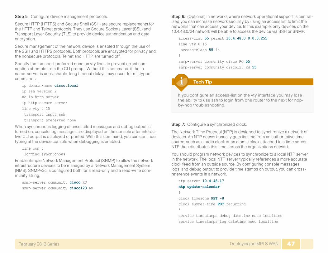
47Deploying an MPLS WANFebruary 2013 Series 47
Step 5: Configure device management protocols.
Secure HTTP (HTTPS) and Secure Shell (SSH) are secure replacements for the HTTP and Telnet protocols. They use Secure Sockets Layer (SSL) and Transport Layer Security (TLS) to provide device authentication and data encryption.
Secure management of the network device is enabled through the use of the SSH and HTTPS protocols. Both protocols are encrypted for privacy and the nonsecure protocols, Telnet and HTTP, are turned off.
Specify the transport preferred none on vty lines to prevent errant con-nection attempts from the CLI prompt. Without this command, if the ip name-server is unreachable, long timeout delays may occur for mistyped commands.
ip domain-name cisco.localip ssh version 2no ip http serverip http secure-serverline vty 0 15 transport input ssh transport preferred none
When synchronous logging of unsolicited messages and debug output is turned on, console log messages are displayed on the console after interac-tive CLI output is displayed or printed. With this command, you can continue typing at the device console when debugging is enabled.
line con 0 logging synchronous
Enable Simple Network Management Protocol (SNMP) to allow the network infrastructure devices to be managed by a Network Management System (NMS). SNMPv2c is configured both for a read-only and a read-write com-munity string.
snmp-server community cisco RO snmp-server community cisco123 RW
Step 6: (Optional) In networks where network operational support is central-ized you can increase network security by using an access list to limit the networks that can access your device. In this example, only devices on the 10.4.48.0/24 network will be able to access the device via SSH or SNMP.
access-list 55 permit 10.4.48.0 0.0.0.255line vty 0 15 access-class 55 in !snmp-server community cisco RO 55 snmp-server community cisco123 RW 55
If you configure an access-list on the vty interface you may lose the ability to use ssh to login from one router to the next for hop-by-hop troubleshooting.
Tech Tip
Step 7: Configure a synchronized clock.
The Network Time Protocol (NTP) is designed to synchronize a network of devices. An NTP network usually gets its time from an authoritative time source, such as a radio clock or an atomic clock attached to a time server. NTP then distributes this time across the organizations network.
You should program network devices to synchronize to a local NTP server in the network. The local NTP server typically references a more accurate clock feed from an outside source. By configuring console messages, logs, and debug output to provide time stamps on output, you can cross-reference events in a network.
ntp server 10.4.48.17ntp update-calendar!clock timezone PST -8 clock summer-time PDT recurring !service timestamps debug datetime msec localtimeservice timestamps log datetime msec localtime
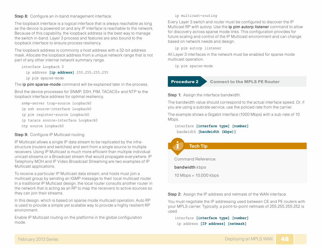
48Deploying an MPLS WANFebruary 2013 Series 48
Step 8: Configure an in-band management interface.
The loopback interface is a logical interface that is always reachable as long as the device is powered on and any IP interface is reachable to the network. Because of this capability, the loopback address is the best way to manage the switch in-band. Layer 3 process and features are also bound to the loopback interface to ensure process resiliency.
The loopback address is commonly a host address with a 32-bit address mask. Allocate the loopback address from a unique network range that is not part of any other internal network summary range.
interface Loopback 0 ip address [ip address] 255.255.255.255 ip pim sparse-mode
The ippimsparse-mode command will be explained later in the process.
Bind the device processes for SNMP, SSH, PIM, TACACS+ and NTP to the loopback interface address for optimal resiliency.
snmp-server trap-source Loopback0ip ssh source-interface Loopback0ip pim register-source Loopback0ip tacacs source-interface Loopback0ntp source Loopback0
Step 9: Configure IP Multicast routing.
IP Multicast allows a single IP data stream to be replicated by the infra-structure (routers and switches) and sent from a single source to multiple receivers. Using IP Multicast is much more efficient than multiple individual unicast streams or a Broadcast stream that would propagate everywhere. IP Telephony MOH and IP Video Broadcast Streaming are two examples of IP Multicast applications.
To receive a particular IP Multicast data stream, end hosts must join a multicast group by sending an IGMP message to their local multicast router. In a traditional IP Multicast design, the local router consults another router in the network that is acting as an RP to map the receivers to active sources so they can join their streams.
In this design, which is based on sparse mode multicast operation, Auto RP is used to provide a simple yet scalable way to provide a highly resilient RP environment.
Enable IP Multicast routing on the platforms in the global configuration mode.
ip multicast-routing
Every Layer 3 switch and router must be configured to discover the IP Multicast RP with autorp. Use the ippimautorplistener command to allow for discovery across sparse mode links. This configuration provides for future scaling and control of the IP Multicast environment and can change based on network needs and design.
ip pim autorp listener
All Layer 3 interfaces in the network must be enabled for sparse mode multicast operation.
ip pim sparse-mode
Procedure 2 Connect to the MPLS PE Router
Step 1: Assign the interface bandwidth.
The bandwidth value should correspond to the actual interface speed. Or, if you are using a subrate service, use the policed rate from the carrier.
The example shows a Gigabit interface (1000 Mbps) with a sub-rate of 10 Mbps.
interface [interface type] [number] bandwidth [bandwidth (kbps)]
Command Reference:
bandwidth kbps
10 Mbps = 10,000 kbps
Tech Tip
Step 2: Assign the IP address and netmask of the WAN interface.
You must negotiate the IP addressing used between CE and PE routers with your MPLS carrier. Typically, a point-to-point netmask of 255.255.255.252 is used.
interface [interface type] [number] ip address [IP address] [netmask]
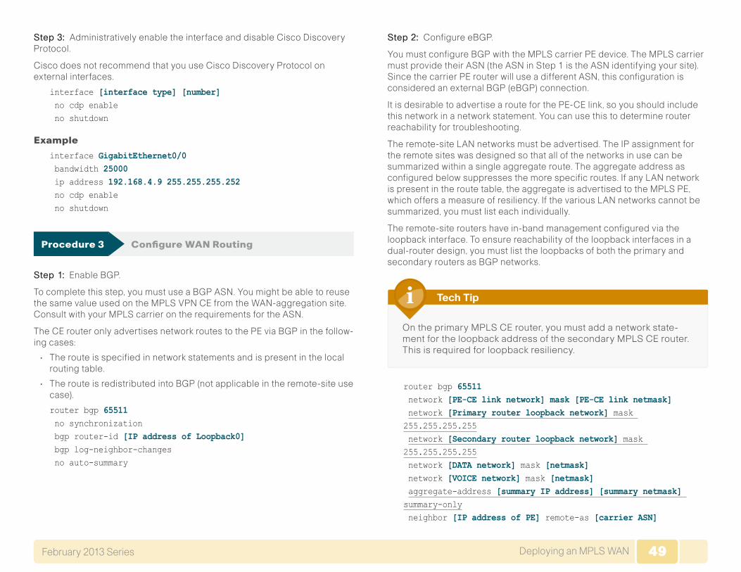
49Deploying an MPLS WANFebruary 2013 Series 49
Step 3: Administratively enable the interface and disable Cisco Discovery Protocol.
Cisco does not recommend that you use Cisco Discovery Protocol on external interfaces.
interface [interface type] [number] no cdp enable no shutdown
Example
interface GigabitEthernet0/0 bandwidth 25000 ip address 192.168.4.9 255.255.255.252 no cdp enable no shutdown
Procedure 3 Configure WAN Routing
Step 1: Enable BGP.
To complete this step, you must use a BGP ASN. You might be able to reuse the same value used on the MPLS VPN CE from the WAN-aggregation site. Consult with your MPLS carrier on the requirements for the ASN.
The CE router only advertises network routes to the PE via BGP in the follow-ing cases:
• The route is specified in network statements and is present in the local routing table.
• The route is redistributed into BGP (not applicable in the remote-site use case).
router bgp 65511 no synchronization bgp router-id [IP address of Loopback0] bgp log-neighbor-changes no auto-summary
Step 2: Configure eBGP.
You must configure BGP with the MPLS carrier PE device. The MPLS carrier must provide their ASN (the ASN in Step 1 is the ASN identifying your site). Since the carrier PE router will use a different ASN, this configuration is considered an external BGP (eBGP) connection.
It is desirable to advertise a route for the PE-CE link, so you should include this network in a network statement. You can use this to determine router reachability for troubleshooting.
The remote-site LAN networks must be advertised. The IP assignment for the remote sites was designed so that all of the networks in use can be summarized within a single aggregate route. The aggregate address as configured below suppresses the more specific routes. If any LAN network is present in the route table, the aggregate is advertised to the MPLS PE, which offers a measure of resiliency. If the various LAN networks cannot be summarized, you must list each individually.
The remote-site routers have in-band management configured via the loopback interface. To ensure reachability of the loopback interfaces in a dual-router design, you must list the loopbacks of both the primary and secondary routers as BGP networks.
On the primary MPLS CE router, you must add a network state-ment for the loopback address of the secondary MPLS CE router. This is required for loopback resiliency.
Tech Tip
router bgp 65511 network [PE-CE link network] mask [PE-CE link netmask] network [Primary router loopback network] mask 255.255.255.255 network [Secondary router loopback network] mask 255.255.255.255 network [DATA network] mask [netmask] network [VOICE network] mask [netmask] aggregate-address [summary IP address] [summary netmask] summary-only neighbor [IP address of PE] remote-as [carrier ASN]

50Deploying an MPLS WANFebruary 2013 Series 50
Step 3: Configure iBGP between the remote-site MPLS CE routers.
The dual-carrier MPLS design requires that a BGP link is configured between the CE routers. Since the CE routers are using the same ASN, this configuration is considered an internal BGP (iBGP) connection.
Note, the iBGP session will not be established until you complete the transit network and EIGRP (LAN side) steps.
router bgp 65511 neighbor [iBGP neighbor Transit Net IP] remote-as 65511 neighbor [iBGP neighbor Transit Net IP] next-hop-self
Step 4: Configure BGP to prevent the remote site from becoming a transit AS.
By default, BGP readvertises all BGP learned routes. In the dual-MPLS design, this means that MPLS-A routes will be advertised to MPLS-B and vice-versa. In certain cases, when a link to a MPLS hub has failed, remote sites will advertise themselves as a transit autonomous system providing access between the two carriers. Unless the remote site has been specifi-cally designed for this type of routing behavior, with a high bandwidth connection, it is a best practice to disable the site from becoming a transit site. You must use a route-map and an as-path access-list filter. You need to apply this route-map on both remote-site MPLS CE routers. Each router will apply this outbound to the neighbor for its respective MPLS carrier.
router bgp 65511 neighbor [IP address of PE 2] route-map NO-TRANSIT-AS out
The regular expression “^$” corresponds to routes originated from the remote-site. This type of filter only allows for the locally originated routes to be advertised.
ip as-path access-list 10 permit ^$!route-map NO-TRANSIT-AS permit 10 match as-path 10
Example - MPLS CE Router (secondary)
router bgp 65511 no synchronization bgp router-id 10.255.252.206 bgp log-neighbor-changes network 192.168.4.8 mask 255.255.255.252 network 10.255.251.206 mask 255.255.255.255 network 10.255.252.206 mask 255.255.255.255 network 10.5.12.0 mask 255.255.255.0 network 10.5.13.0 mask 255.255.255.0 aggregate-address 10.5.8.0 255.255.248.0 summary-only neighbor 10.5.8.1 remote-as 65511 neighbor 10.5.8.1 next-hop-self neighbor 192.168.4.10 remote-as 65402 neighbor 192.168.4.10 route-map NO-TRANSIT-AS out no auto-summary!ip as-path access-list 10 permit ^$!route-map NO-TRANSIT-AS permit 10 match as-path 10
Procedure 4 Connect Router to Access Layer Switch
Please refer to the LAN Deployment Guide for complete access layer configuration details. This guide only includes the additional steps to complete the distribution layer configuration.
If you are using a remote-site distribution layer then skip to the “Deploying a WAN Remote-Site Distribution Layer” section of this guide.
Reader Tip
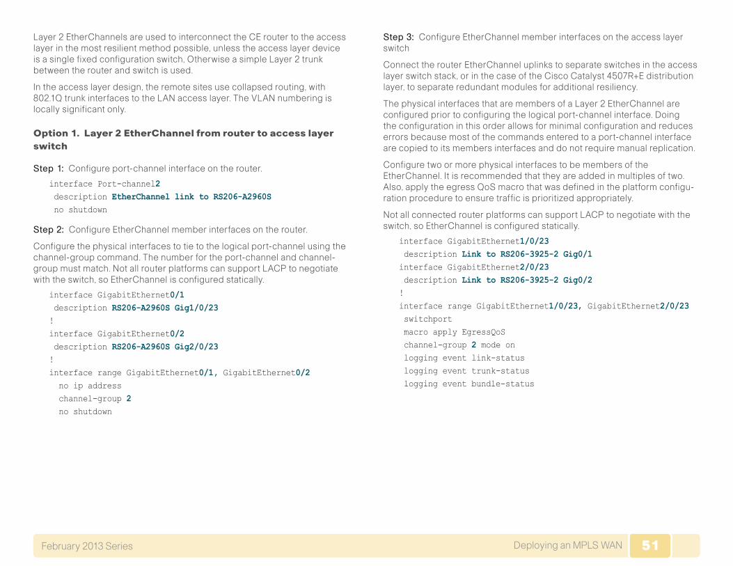
51Deploying an MPLS WANFebruary 2013 Series 51
Layer 2 EtherChannels are used to interconnect the CE router to the access layer in the most resilient method possible, unless the access layer device is a single fixed configuration switch, Otherwise a simple Layer 2 trunk between the router and switch is used.
In the access layer design, the remote sites use collapsed routing, with 802.1Q trunk interfaces to the LAN access layer. The VLAN numbering is locally significant only.
Option 1. Layer 2 EtherChannel from router to access layer switch
Step 1: Configure port-channel interface on the router.
interface Port-channel2 description EtherChannel link to RS206-A2960S no shutdown
Step 2: Configure EtherChannel member interfaces on the router.
Configure the physical interfaces to tie to the logical port-channel using the channel-group command. The number for the port-channel and channel-group must match. Not all router platforms can support LACP to negotiate with the switch, so EtherChannel is configured statically.
interface GigabitEthernet0/1 description RS206-A2960S Gig1/0/23!interface GigabitEthernet0/2 description RS206-A2960S Gig2/0/23!interface range GigabitEthernet0/1, GigabitEthernet0/2 no ip address channel-group 2 no shutdown
Step 3: Configure EtherChannel member interfaces on the access layer switch
Connect the routerEtherChannel uplinks to separate switches in the access layer switch stack, or in the case of the Cisco Catalyst 4507R+E distribution layer, to separate redundant modules for additional resiliency.
The physical interfaces that are members of a Layer 2 EtherChannel are configured prior to configuring the logical port-channel interface. Doing the configuration in this order allows for minimal configuration and reduces errors because most of the commands entered to a port-channel interface are copied to its members interfaces and do not require manual replication.
Configure two or more physical interfaces to be members of the EtherChannel. It is recommended that they are added in multiples of two. Also, apply the egress QoS macro that was defined in the platform configu-ration procedure to ensure traffic is prioritized appropriately.
Not all connected router platforms can support LACP to negotiate with the switch, so EtherChannel is configured statically.
interface GigabitEthernet1/0/23 description Link to RS206-3925-2 Gig0/1interface GigabitEthernet2/0/23 description Link to RS206-3925-2 Gig0/2!interface range GigabitEthernet1/0/23, GigabitEthernet2/0/23 switchport macro apply EgressQoS channel-group 2 mode on logging event link-status logging event trunk-status logging event bundle-status
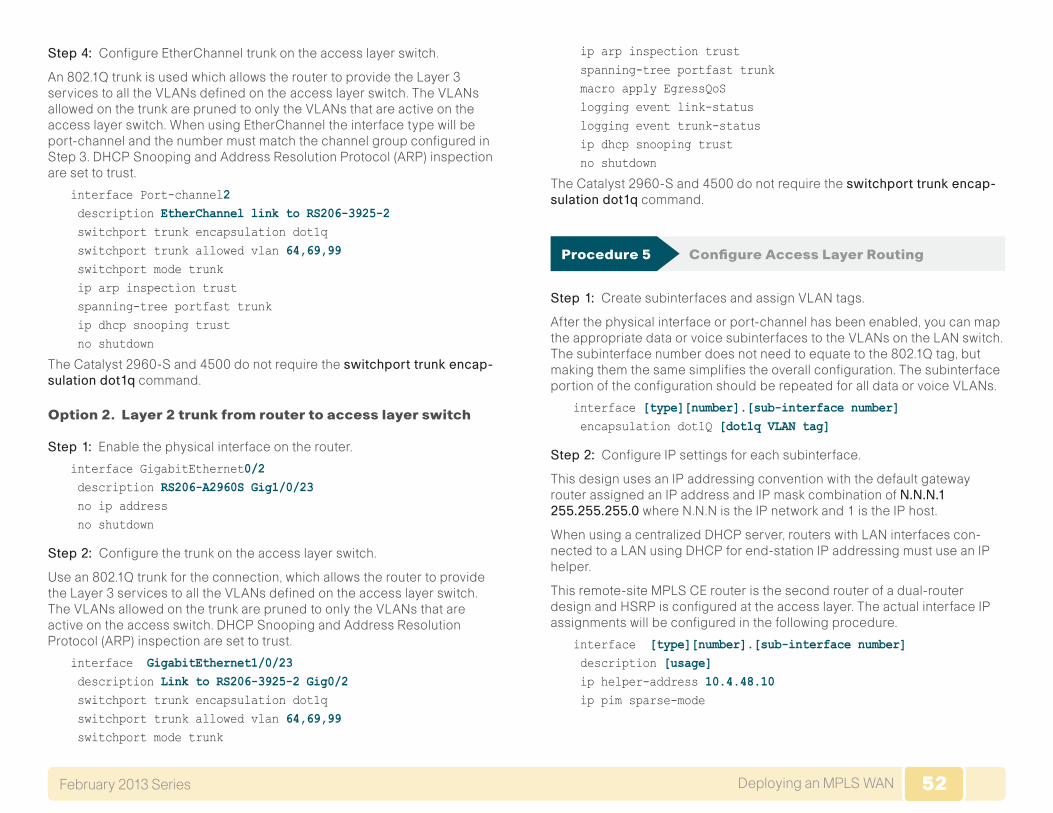
52Deploying an MPLS WANFebruary 2013 Series 52
Step 4: Configure EtherChannel trunk on the access layer switch.
An 802.1Q trunk is used which allows the router to provide the Layer 3 services to all the VLANs defined on theaccess layer switch. The VLANs allowed on the trunk are pruned to only the VLANs that are active on the access layer switch. When using EtherChannel the interface type will be port-channel and the number must match the channel group configured in Step 3. DHCP Snooping and Address Resolution Protocol (ARP) inspection are set to trust.
interface Port-channel2 description EtherChannel link to RS206-3925-2 switchport trunk encapsulation dot1q switchport trunk allowed vlan 64,69,99 switchport mode trunk ip arp inspection trust spanning-tree portfast trunk ip dhcp snooping trust no shutdown
The Catalyst 2960-S and 4500 do not require the switchporttrunkencap-sulationdot1q command.
Option 2. Layer 2 trunk from router to access layer switch
Step 1: Enable the physical interface on the router.
interface GigabitEthernet0/2 description RS206-A2960S Gig1/0/23 no ip address no shutdown
Step 2: Configure the trunk on the access layer switch.
Use an 802.1Q trunk for the connection, which allows the router to provide the Layer 3 services to all the VLANs defined on the access layer switch. The VLANs allowed on the trunk are pruned to only the VLANs that are active on the access switch. DHCP Snooping and Address Resolution Protocol (ARP) inspection are set to trust.
interface GigabitEthernet1/0/23 description Link to RS206-3925-2 Gig0/2 switchport trunk encapsulation dot1q switchport trunk allowed vlan 64,69,99 switchport mode trunk
ip arp inspection trust spanning-tree portfast trunk macro apply EgressQoS logging event link-status logging event trunk-status ip dhcp snooping trust no shutdown
The Catalyst 2960-S and 4500 do not require the switchporttrunkencap-sulationdot1q command.
Procedure 5 Configure Access Layer Routing
Step 1: Create subinterfaces and assign VLAN tags.
After the physical interface or port-channel has been enabled, you can map the appropriate data or voice subinterfaces to the VLANs on the LAN switch. The subinterface number does not need to equate to the 802.1Q tag, but making them the same simplifies the overall configuration. The subinterface portion of the configuration should be repeated for all data or voice VLANs.
interface [type][number].[sub-interface number] encapsulation dot1Q [dot1q VLAN tag]
Step 2: Configure IP settings for each subinterface.
This design uses an IP addressing convention with the default gateway router assigned an IP address and IP mask combination of N.N.N.1255.255.255.0 where N.N.N is the IP network and 1 is the IP host.
When using a centralized DHCP server, routers with LAN interfaces con-nected to a LAN using DHCP for end-station IP addressing must use an IP helper.
This remote-site MPLS CE router is the second router of a dual-router design and HSRP is configured at the access layer. The actual interface IP assignments will be configured in the following procedure.
interface [type][number].[sub-interface number] description [usage] ip helper-address 10.4.48.10 ip pim sparse-mode
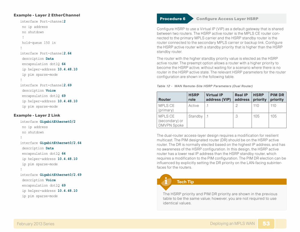
53Deploying an MPLS WANFebruary 2013 Series 53
Example - Layer 2 EtherChannel
interface Port-channel2 no ip address no shutdown ! hold-queue 150 in!interface Port-channel2.64 description Data encapsulation dot1Q 64 ip helper-address 10.4.48.10 ip pim sparse-mode!interface Port-channel2.69 description Voice encapsulation dot1Q 69 ip helper-address 10.4.48.10 ip pim sparse-mode
Example - Layer 2 Link
interface GigabitEthernet0/2 no ip address no shutdown!interface GigabitEthernet0/2.64 description Data encapsulation dot1Q 64 ip helper-address 10.4.48.10 ip pim sparse-mode!interface GigabitEthernet0/2.69 description Voice encapsulation dot1Q 69 ip helper-address 10.4.48.10 ip pim sparse-mode
Procedure 6 Configure Access Layer HSRP
Configure HSRP to use a Virtual IP (VIP) as a default gateway that is shared between two routers. The HSRP active router is the MPLS CE router con-nected to the primary MPLS carrier and the HSRP standby router is the router connected to the secondary MPLS carrier or backup link. Configure the HSRP active router with a standby priority that is higher than the HSRP standby router.
The router with the higher standby priority value is elected as the HSRP active router. The preempt option allows a router with a higher priority to become the HSRP active, without waiting for a scenario where there is no router in the HSRP active state. The relevant HSRP parameters for the router configuration are shown in the following table.
Table 12 - WAN Remote-Site HSRP Parameters (Dual Router)
Router HSRP role
Virtual IP address (VIP)
Real IP address
HSRP priority
PIM DR priority
MPLS CE (primary)
Active .1 .2 110 110
MPLS CE (secondary) or DMVPN Spoke
Standby .1 .3 105 105
The dual-router access-layer design requires a modification for resilient multicast. The PIM designated router (DR) should be on the HSRP active router. The DR is normally elected based on the highest IP address, and has no awareness of the HSRP configuration. In this design, the HSRP active router has a lower real IP address than the HSRP standby router, which requires a modification to the PIM configuration. The PIM DR election can be influenced by explicitly setting the DR priority on the LAN-facing subinter-faces for the routers.
The HSRP priority and PIM DR priority are shown in the previous table to be the same value; however, you are not required to use identical values.
Tech Tip
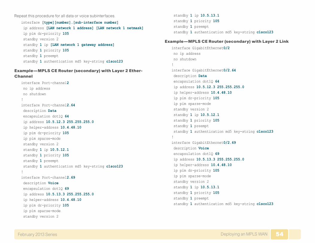
54Deploying an MPLS WANFebruary 2013 Series 54
Repeat this procedure for all data or voice subinterfaces.
interface [type][number].[sub-interface number] ip address [LAN network 1 address] [LAN network 1 netmask] ip pim dr-priority 105 standby version 2 standby 1 ip [LAN network 1 gateway address] standby 1 priority 105 standby 1 preempt standby 1 authentication md5 key-string c1sco123
Example—MPLS CE Router (secondary) with Layer 2 Ether-Channel
interface Port-channel2 no ip address no shutdown!interface Port-channel2.64 description Data encapsulation dot1Q 64 ip address 10.5.12.3 255.255.255.0 ip helper-address 10.4.48.10 ip pim dr-priority 105 ip pim sparse-mode standby version 2 standby 1 ip 10.5.12.1 standby 1 priority 105 standby 1 preempt standby 1 authentication md5 key-string c1sco123!interface Port-channel2.69 description Voice encapsulation dot1Q 69 ip address 10.5.13.3 255.255.255.0 ip helper-address 10.4.48.10 ip pim dr-priority 105 ip pim sparse-mode standby version 2
standby 1 ip 10.5.13.1 standby 1 priority 105 standby 1 preempt standby 1 authentication md5 key-string c1sco123
Example—MPLS CE Router (secondary) with Layer 2 Link
interface GigabitEthernet0/2 no ip address no shutdown!interface GigabitEthernet0/2.64 description Data encapsulation dot1Q 64 ip address 10.5.12.3 255.255.255.0 ip helper-address 10.4.48.10 ip pim dr-priority 105 ip pim sparse-mode standby version 2 standby 1 ip 10.5.12.1 standby 1 priority 105 standby 1 preempt standby 1 authentication md5 key-string c1sco123!interface GigabitEthernet0/2.69 description Voice encapsulation dot1Q 69 ip address 10.5.13.3 255.255.255.0 ip helper-address 10.4.48.10 ip pim dr-priority 105 ip pim sparse-mode standby version 2 standby 1 ip 10.5.13.1 standby 1 priority 105 standby 1 preempt standby 1 authentication md5 key-string c1sco123
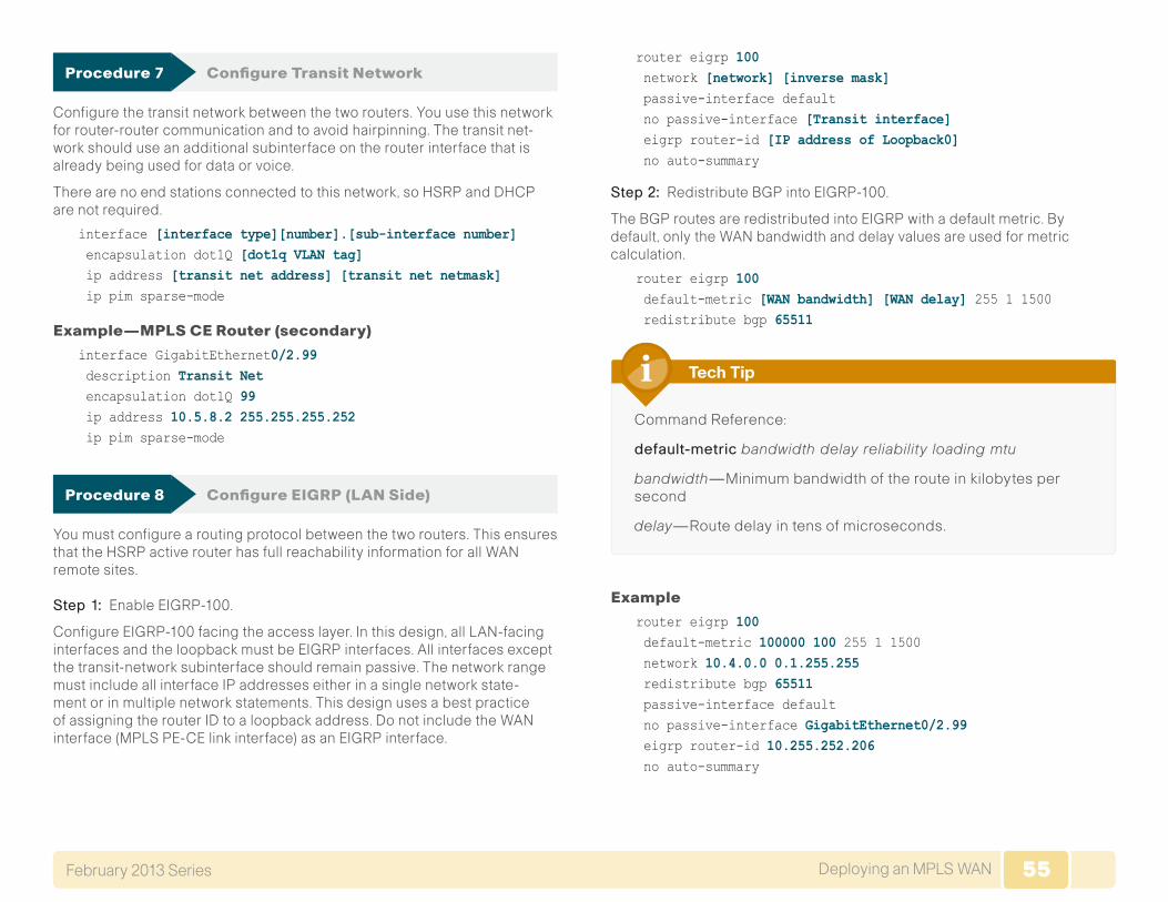
55Deploying an MPLS WANFebruary 2013 Series 55
Procedure 7 Configure Transit Network
Configure the transit network between the two routers. You use this network for router-router communication and to avoid hairpinning. The transit net-work should use an additional subinterface on the router interface that is already being used for data or voice.
There are no end stations connected to this network, so HSRP and DHCP are not required.
interface [interface type][number].[sub-interface number] encapsulation dot1Q [dot1q VLAN tag] ip address [transit net address] [transit net netmask] ip pim sparse-mode
Example—MPLS CE Router (secondary)
interface GigabitEthernet0/2.99 description Transit Net encapsulation dot1Q 99 ip address 10.5.8.2 255.255.255.252 ip pim sparse-mode
Procedure 8 Configure EIGRP (LAN Side)
You must configure a routing protocol between the two routers. This ensures that the HSRP active router has full reachability information for all WAN remote sites.
Step 1: Enable EIGRP-100.
Configure EIGRP-100 facing the access layer. In this design, all LAN-facing interfaces and the loopback must be EIGRP interfaces. All interfaces except the transit-network subinterface should remain passive. The network range must include all interface IP addresses either in a single network state-ment or in multiple network statements. This design uses a best practice of assigning the router ID to a loopback address. Do not include the WAN interface (MPLS PE-CE link interface) as an EIGRP interface.
router eigrp 100 network [network] [inverse mask] passive-interface default no passive-interface [Transit interface] eigrp router-id [IP address of Loopback0] no auto-summary
Step 2: Redistribute BGP into EIGRP-100.
The BGP routes are redistributed into EIGRP with a default metric. By default, only the WAN bandwidth and delay values are used for metric calculation.
router eigrp 100 default-metric [WAN bandwidth] [WAN delay] 255 1 1500 redistribute bgp 65511
Command Reference:
default-metricbandwidth delay reliability loading mtu
bandwidth—Minimum bandwidth of the route in kilobytes per second
delay—Route delay in tens of microseconds.
Tech Tip
Example
router eigrp 100 default-metric 100000 100 255 1 1500 network 10.4.0.0 0.1.255.255 redistribute bgp 65511 passive-interface default no passive-interface GigabitEthernet0/2.99 eigrp router-id 10.255.252.206 no auto-summary
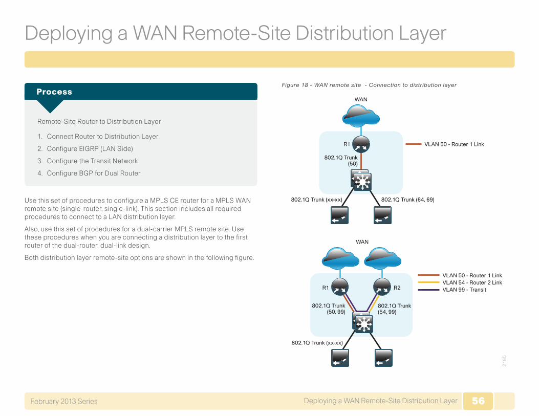
56Deploying a WAN Remote-Site Distribution LayerFebruary 2013 Series 56
Deploying a WAN Remote-Site Distribution Layer
Remote-Site Router to Distribution Layer
1. Connect Router to Distribution Layer
2. Configure EIGRP (LAN Side)
3. Configure the Transit Network
4. Configure BGP for Dual Router
Process
Use this set of procedures to configure a MPLS CE router for a MPLS WAN remote site (single-router, single-link). This section includes all required procedures to connect to a LAN distribution layer.
Also, use this set of procedures for a dual-carrier MPLS remote site. Use these procedures when you are connecting a distribution layer to the first router of the dual-router, dual-link design.
Both distribution layer remote-site options are shown in the following figure.
Figure 18 - WAN remote site - Connection to distribution layer
21
85
WAN
WAN
VLAN 50 - Router 1 Link
VLAN 50 - Router 1 Link
802.1Q Trunk(50)
R1
R1 R2
802.1Q Trunk (xx-xx) 802.1Q Trunk (64, 69)
802.1Q Trunk (xx-xx)
802.1Q Trunk(50, 99)
802.1Q Trunk(54, 99)
VLAN 54 - Router 2 LinkVLAN 99 - Transit
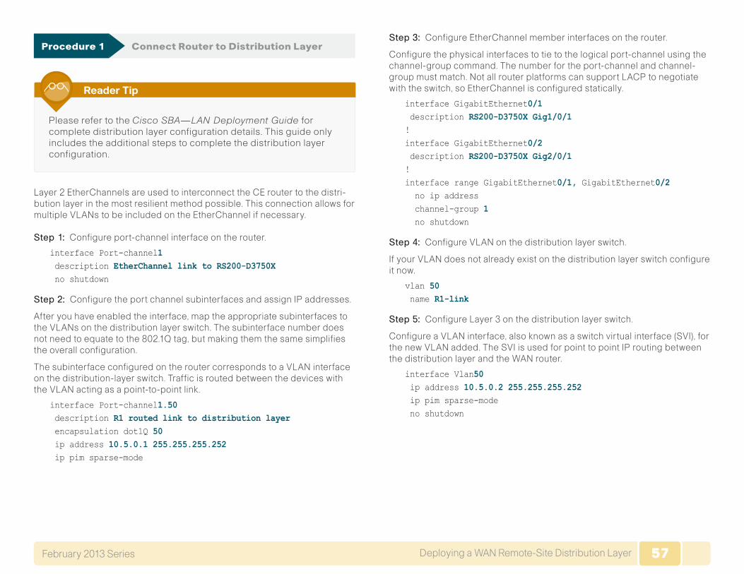
57Deploying a WAN Remote-Site Distribution LayerFebruary 2013 Series 57
Procedure 1 Connect Router to Distribution Layer
Please refer to the Cisco SBA—LAN Deployment Guide for complete distribution layer configuration details. This guide only includes the additional steps to complete the distribution layer configuration.
Reader Tip
Layer 2 EtherChannels are used to interconnect the CE router to the distri-bution layer in the most resilient method possible. This connection allows for multiple VLANs to be included on the EtherChannel if necessary.
Step 1: Configure port-channel interface on the router.
interface Port-channel1 description EtherChannel link to RS200-D3750X no shutdown
Step 2: Configure the port channel subinterfaces and assign IP addresses.
After you have enabled the interface, map the appropriate subinterfaces to the VLANs on the distribution layer switch. The subinterface number does not need to equate to the 802.1Q tag, but making them the same simplifies the overall configuration.
The subinterface configured on the router corresponds to a VLAN interface on the distribution-layer switch. Traffic is routed between the devices with the VLAN acting as a point-to-point link.
interface Port-channel1.50 description R1 routed link to distribution layer encapsulation dot1Q 50 ip address 10.5.0.1 255.255.255.252 ip pim sparse-mode
Step 3: Configure EtherChannel member interfaces on the router.
Configure the physical interfaces to tie to the logical port-channel using the channel-group command. The number for the port-channel and channel-group must match. Not all router platforms can support LACP to negotiate with the switch, so EtherChannel is configured statically.
interface GigabitEthernet0/1 description RS200-D3750X Gig1/0/1!interface GigabitEthernet0/2 description RS200-D3750X Gig2/0/1!interface range GigabitEthernet0/1, GigabitEthernet0/2 no ip address channel-group 1 no shutdown
Step 4: Configure VLAN on the distribution layer switch.
If your VLAN does not already exist on the distribution layer switch configure it now.
vlan 50 name R1-link
Step 5: Configure Layer 3 on the distribution layer switch.
Configure a VLAN interface, also known as a switch virtual interface (SVI), for the new VLAN added. The SVI is used for point to point IP routing between the distribution layer and the WAN router.
interface Vlan50 ip address 10.5.0.2 255.255.255.252 ip pim sparse-mode no shutdown
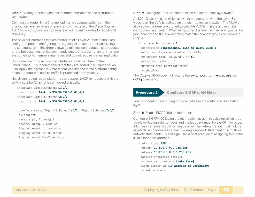
58Deploying a WAN Remote-Site Distribution LayerFebruary 2013 Series 58
Step 6: Configure EtherChannel member interfaces on the distribution layer switch.
Connect the routerEtherChannel uplinks to separate switches in the distribution layer switches or stack, and in the case of the Cisco Catalyst 4507R+E distribution layer, to separate redundant modules for additional resiliency.
The physical interfaces that are members of a Layer 2 EtherChannel are configured prior to configuring the logical port-channel interface. Doing the configuration in this order allows for minimal configuration and reduces errors because most of the commands entered to a port-channel interface are copied to its members interfaces and do not require manual replication.
Configure two or more physical interfaces to be members of the EtherChannel. It is recommended that they are added in multiples of two. Also, apply the egress QoS macro that was defined in the platform configu-ration procedure to ensure traffic is prioritized appropriately.
Not all connected router platforms can support LACP to negotiate with the switch, so EtherChannel is configured statically.
interface GigabitEthernet1/0/1 description Link to RS200-3925-1 Gig0/1interface GigabitEthernet2/0/1 description Link to RS200-3925-1 Gig0/2!interface range GigabitEthernet1/0/1, GigabitEthernet2/0/1 switchport macro apply EgressQoS channel-group 1 mode on logging event link-status logging event trunk-status logging event bundle-status
Step 7: Configure EtherChannel trunk on the distribution layer switch.
An 802.1Q trunk is used which allows the router to provide the Layer 3 ser-vices to all the VLANs defined on thedistribution layer switch. The VLANs allowed on the trunk are pruned to only the VLANs that are active on the distribution layer switch. When using EtherChannel the interface type will be port-channel and the number must match the channel group configured in Step 3.
interface Port-channel1 description EtherChannel link to RS200-3925-1 switchport trunk encapsulation dot1q switchport trunk allowed vlan 50 switchport mode trunk spanning-tree portfast trunk no shutdown
The Catalyst 4500 does not require the switchporttrunkencapsulationdot1q command.
Procedure 2 Configure EIGRP (LAN Side)
You must configure a routing protocol between the router and distribution layer.
Step 1: Enable EIGRP-100 on the router.
Configure EIGRP-100 facing the distribution layer. In this design, all distribu-tion-layer-facing subinterfaces and the loopback must be EIGRP interfaces. All other interfaces should remain passive. The network range must include all interface IP addresses either in a single network statement or in multiple network statements. This design uses a best practice of assigning the router ID to a loopback address.
router eigrp 100 network 10.5.0.0 0.0.255.255 network 10.255.0.0 0.0.255.255 passive-interface default no passive-interface [interface] eigrp router-id [IP address of Loopback0] no auto-summary
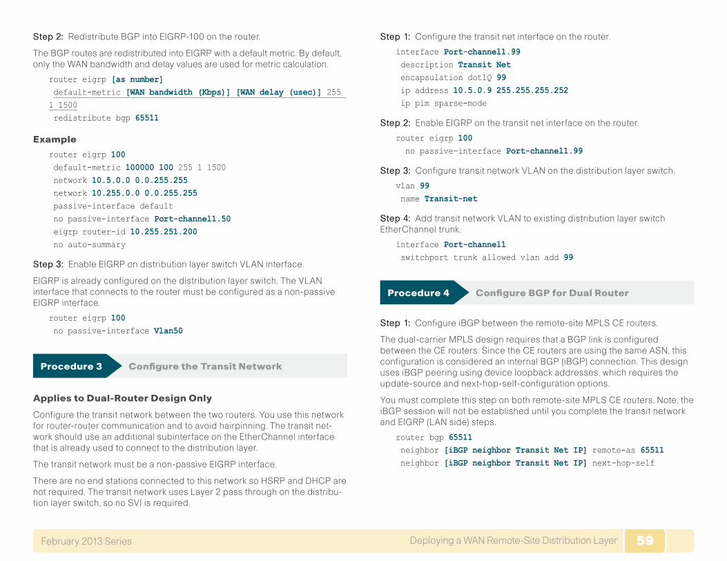
59Deploying a WAN Remote-Site Distribution LayerFebruary 2013 Series 59
Step 2: Redistribute BGP into EIGRP-100 on the router.
The BGP routes are redistributed into EIGRP with a default metric. By default, only the WAN bandwidth and delay values are used for metric calculation.
router eigrp [as number] default-metric [WAN bandwidth (Kbps)] [WAN delay (usec)] 255 1 1500 redistribute bgp 65511
Example
router eigrp 100 default-metric 100000 100 255 1 1500 network 10.5.0.0 0.0.255.255 network 10.255.0.0 0.0.255.255 passive-interface default no passive-interface Port-channel1.50 eigrp router-id 10.255.251.200 no auto-summary
Step 3: Enable EIGRP on distribution layer switch VLAN interface.
EIGRP is already configured on the distribution layer switch. The VLAN interface that connects to the router must be configured as a non-passive EIGRP interface.
router eigrp 100 no passive-interface Vlan50
Procedure 3 Configure the Transit Network
Applies to Dual-Router Design Only
Configure the transit network between the two routers. You use this network for router-router communication and to avoid hairpinning. The transit net-work should use an additional subinterface on the EtherChannel interface that is already used to connect to the distribution layer.
The transit network must be a non-passive EIGRP interface.
There are no end stations connected to this network so HSRP and DHCP are not required. The transit network uses Layer 2 pass through on the distribu-tion layer switch, so no SVI is required.
Step 1: Configure the transit net interface on the router.
interface Port-channel1.99 description Transit Net encapsulation dot1Q 99 ip address 10.5.0.9 255.255.255.252 ip pim sparse-mode
Step 2: Enable EIGRP on the transit net interface on the router.
router eigrp 100 no passive-interface Port-channel1.99
Step 3: Configure transit network VLAN on the distribution layer switch.
vlan 99 name Transit-net
Step 4: Add transit network VLAN to existing distribution layer switch EtherChannel trunk.
interface Port-channel1 switchport trunk allowed vlan add 99
Procedure 4 Configure BGP for Dual Router
Step 1: Configure iBGP between the remote-site MPLS CE routers.
The dual-carrier MPLS design requires that a BGP link is configured between the CE routers. Since the CE routers are using the same ASN, this configuration is considered an internal BGP (iBGP) connection. This design uses iBGP peering using device loopback addresses, which requires the update-source and next-hop-self-configuration options.
You must complete this step on both remote-site MPLS CE routers. Note, the iBGP session will not be established until you complete the transit network and EIGRP (LAN side) steps.
router bgp 65511 neighbor [iBGP neighbor Transit Net IP] remote-as 65511 neighbor [iBGP neighbor Transit Net IP] next-hop-self
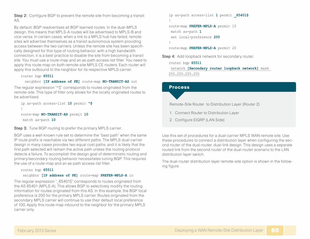
60Deploying a WAN Remote-Site Distribution LayerFebruary 2013 Series 60
Step 2: Configure BGP to prevent the remote site from becoming a transit AS.
By default, BGP readvertises all BGP learned routes. In the dual-MPLS design, this means that MPLS-A routes will be advertised to MPLS-B and vice-versa. In certain cases, when a link to a MPLS hub has failed, remote sites will advertise themselves as a transit autonomous system providing access between the two carriers. Unless the remote site has been specifi-cally designed for this type of routing behavior, with a high bandwidth connection, it is a best practice to disable the site from becoming a transit site. You must use a route-map and an as-path access-list filter. You need to apply this route-map on both remote-site MPLS CE routers. Each router will apply this outbound to the neighbor for its respective MPLS carrier.
router bgp 65511 neighbor [IP address of PE] route-map NO-TRANSIT-AS out
The regular expression “^$” corresponds to routes originated from the remote-site. This type of filter only allows for the locally originated routes to be advertised.
ip as-path access-list 10 permit ^$!route-map NO-TRANSIT-AS permit 10 match as-path 10
Step 3: Tune BGP routing to prefer the primary MPLS carrier.
BGP uses a well-known rule set to determine the “best path” when the same IP route prefix is reachable via two different paths. The MPLS dual-carrier design in many cases provides two equal cost paths, and it is likely that the first path selected will remain the active path unless the routing protocol detects a failure. To accomplish the design goal of deterministic routing and primary/secondary routing behavior necessitates tuning BGP. This requires the use of a route-map and an as-path access-list filter.
router bgp 65511 neighbor [IP address of PE] route-map PREFER-MPLS-A in
The regular expression “_65401$” corresponds to routes originated from the AS 65401 (MPLS-A). This allows BGP to selectively modify the routing information for routes originated from this AS. In this example, the BGP local preference is 200 for the primary MPLS carrier. Routes originated from the secondary MPLS carrier will continue to use their default local preference of 100. Apply this route-map inbound to the neighbor for the primary MPLS carrier only.
ip as-path access-list 1 permit _65401$!route-map PREFER-MPLS-A permit 10 match as-path 1 set local-preference 200!route-map PREFER-MPLS-A permit 20
Step 4: Add loopback network for secondary router.
router bgp 65511 network [Secondary router loopback network] mask 255.255.255.255
Remote-Site Router to Distribution Layer (Router 2)
1. Connect Router to Distribution Layer
2. Configure EIGRP (LAN Side)
Process
Use this set of procedures for a dual-carrier MPLS WAN remote site. Use these procedures to connect a distribution layer when configuring the sec-ond router of the dual-router, dual-link design. This design uses a separate routed link from the second router of the dual-router scenario to the LAN distribution layer switch.
The dual-router distribution layer remote-site option is shown in the follow-ing figure.
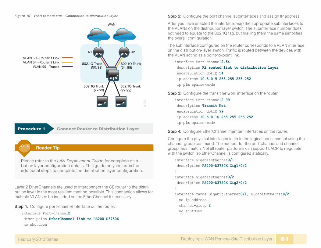
61Deploying a WAN Remote-Site Distribution LayerFebruary 2013 Series 61
Figure 19 - WAN remote site - Connection to distribution layer
21
32
WAN
R1 R2
VLAN 50 - Router 1 Link
802.1Q Trunk(xx-xx)
802.1Q Trunk(yy-yy)
802.1Q Trunk(50, 99)
802.1Q Trunk(54, 99)
VLAN 54 - Router 2 LinkVLAN 99 - Transit
Procedure 1 Connect Router to Distribution Layer
Please refer to the LAN Deployment Guide for complete distri-bution layer configuration details. This guide only includes the additional steps to complete the distribution layer configuration.
Reader Tip
Layer 2 EtherChannels are used to interconnect the CE router to the distri-bution layer in the most resilient method possible. This connection allows for multiple VLANs to be included on the EtherChannel if necessary.
Step 1: Configure port-channel interface on the router.
interface Port-channel2 description EtherChannel link to RS200-D3750X no shutdown
Step 2: Configure the port channel subinterfaces and assign IP address.
After you have enabled the interface, map the appropriate subinterfaces to the VLANs on the distribution layer switch. The subinterface number does not need to equate to the 802.1Q tag, but making them the same simplifies the overall configuration.
The subinterface configured on the router corresponds to a VLAN interface on the distribution-layer switch. Traffic is routed between the devices with the VLAN acting as a point-to-point link.
interface Port-channel2.54 description R2 routed link to distribution layer encapsulation dot1Q 54 ip address 10.5.0.5 255.255.255.252 ip pim sparse-mode
Step 3: Configure the transit network interface on the router.
interface Port-channel2.99 description Transit Net encapsulation dot1Q 99 ip address 10.5.0.10 255.255.255.252 ip pim sparse-mode
Step 4: Configure EtherChannel member interfaces on the router.
Configure the physical interfaces to tie to the logical port-channel using the channel-group command. The number for the port-channel and channel-group must match. Not all router platforms can support LACP to negotiate with the switch, so EtherChannel is configured statically.
interface GigabitEthernet0/1 description RS200-D3750X Gig1/0/2!interface GigabitEthernet0/2 description RS200-D3750X Gig2/0/2!interface range GigabitEthernet0/1, GigabitEthernet0/2 no ip address channel-group 2 no shutdown
62Deploying a WAN Remote-Site Distribution LayerFebruary 2013 Series 62
Step 5: Configure VLAN on the distribution layer switch.
If your VLAN does not already exist on the distribution layer switch, config-ure it now.
vlan 54 name R2-link
Step 6: Configure Layer 3 on the distribution layer switch.
Configure a VLAN interface, also known as a switch virtual interface (SVI), for the new VLAN added. The SVI is used for point to point IP routing between the distribution layer and the WAN router.
interface Vlan54 ip address 10.5.0.6 255.255.255.252 ip pim sparse-mode no shutdown
Step 7: Configure EtherChannel member interfaces on the distribution layer switch.
Connect the routerEtherChannel uplinks to separate switches in the distribution layer switches or stack, and in the case of the Cisco Catalyst 4507R+E distribution layer, to separate redundant modules for additional resiliency.
The physical interfaces that are members of a Layer 2 EtherChannel are configured prior to configuring the logical port-channel interface. Doing the configuration in this order allows for minimal configuration and reduces errors because most of the commands entered to a port-channel interface are copied to its members interfaces and do not require manual replication.
Configure two or more physical interfaces to be members of the EtherChannel. It is recommended that they are added in multiples of two. Also, apply the egress QoS macro that was defined in the platform configu-ration procedure to ensure traffic is prioritized appropriately.
Not all connected router platforms can support LACP to negotiate with the switch, so EtherChannel is configured statically.
interface GigabitEthernet1/0/2 description Link to RS200-3925-2 Gig0/1interface GigabitEthernet2/0/2 description Link to RS200-3925-2 Gig0/2!interface range GigabitEthernet1/0/2, GigabitEthernet2/0/2 switchport macro apply EgressQoS channel-group 2 mode on logging event link-status logging event trunk-status logging event bundle-status
Step 8: Configure EtherChannel trunk on the distribution layer switch.
An 802.1Q trunk is used which allows the router to provide the Layer 3 ser-vices to all the VLANs defined on thedistribution layer switch. The VLANs allowed on the trunk are pruned to only the VLANs that are active on the distribution layer switch. When using EtherChannel the interface type will be port-channel and the number must match the channel group configured in Step 3.
interface Port-channel2 description EtherChannel link to RS200-3925-2 switchport trunk encapsulation dot1q switchport trunk allowed vlan 54,99 switchport mode trunk spanning-tree portfast trunk no shutdown
The Catalyst 4500 does not require the switchporttrunkencapsulationdot1q command.
63Deploying a WAN Remote-Site Distribution LayerFebruary 2013 Series 63
Procedure 2 Configure EIGRP (LAN Side)
You must configure a routing protocol between the router and distribution layer.
Step 1: Enable EIGRP-100 on the router.
Configure EIGRP-100 facing the distribution layer. In this design, all distribu-tion-layer-facing subinterfaces and the loopback must be EIGRP interfaces. All other interfaces should remain passive. The network range must include all interface IP addresses either in a single network statement or in multiple network statements. This design uses a best practice of assigning the router ID to a loopback address.
router eigrp 100 network 10.5.0.0 0.0.255.255 network 10.255.0.0 0.0.255.255 passive-interface default no passive-interface [routed link interface] no passive-interface [transit net interface] eigrp router-id [IP address of Loopback0] no auto-summary
Step 2: Redistribute BGP into EIGRP-100 on the router.
The BGP routes are redistributed into EIGRP with a default metric. By default, only the WAN bandwidth and delay values are used for metric calculation.
router eigrp [as number] default-metric [WAN bandwidth (Kbps)] [WAN delay (usec)] 255 1 1500 redistribute bgp 65511
Example
router eigrp 100 default-metric 500000 100 255 1 1500 network 10.5.0.0 0.0.255.255 network 10.255.0.0 0.0.255.255 passive-interface default no passive-interface Port-channel2.54 no passive-interface Port-channel2.99 eigrp router-id 10.255.252.200 no auto-summary
Step 3: Enable EIGRP on distribution layer switch VLAN interface.
EIGRP is already configured on the distribution layer switch. The VLAN interface that connects to the router must be configured as a non-passive EIGRP interface.
router eigrp 100 no passive-interface Vlan54
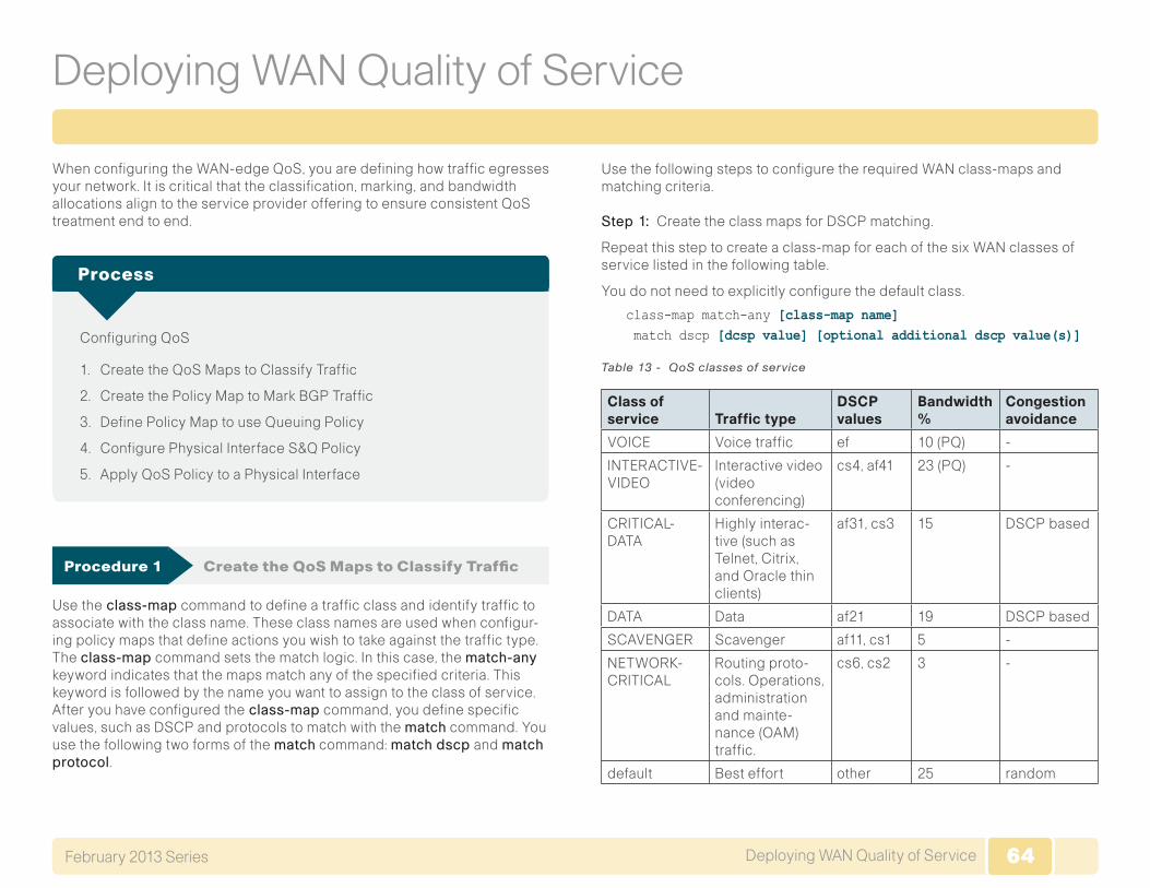
64Deploying WAN Quality of ServiceFebruary 2013 Series 64
Deploying WAN Quality of Service
When configuring the WAN-edge QoS, you are defining how traffic egresses your network. It is critical that the classification, marking, and bandwidth allocations align to the service provider offering to ensure consistent QoS treatment end to end.
Configuring QoS
1. Create the QoS Maps to Classify Traffic
2. Create the Policy Map to Mark BGP Traffic
3. Define Policy Map to use Queuing Policy
4. Configure Physical Interface S&Q Policy
5. Apply QoS Policy to a Physical Interface
Process
Procedure 1 Create the QoS Maps to Classify Traffic
Use theclass-map command to define a traffic class and identify traffic to associate with the class name. These class names are used when configur-ing policy maps that define actions you wish to take against the traffic type. The class-map command sets the match logic. In this case, the match-any keyword indicates that the maps match any of the specified criteria. This keyword is followed by the name you want to assign to the class of service. After you have configured theclass-map command, you define specific values, such as DSCP and protocols to match with the match command. You use the following two forms of the match command: matchdscp and matchprotocol.
Use the following steps to configure the required WAN class-maps and matching criteria.
Step 1: Create the class maps for DSCP matching.
Repeat this step to create a class-map for each of the six WAN classes of service listed in the following table.
You do not need to explicitly configure the default class.
class-map match-any [class-map name] match dscp [dcsp value] [optional additional dscp value(s)]
Table 13 - QoS classes of service
Class of service Traffic type
DSCP values
Bandwidth %
Congestion avoidance
VOICE Voice traffic ef 10 (PQ) -
INTERACTIVE-VIDEO
Interactive video (video conferencing)
cs4, af41 23 (PQ) -
CRITICAL-DATA
Highly interac-tive (such as Telnet, Citrix, and Oracle thin clients)
af31, cs3 15 DSCP based
DATA Data af21 19 DSCP based
SCAVENGER Scavenger af11, cs1 5 -
NETWORK-CRITICAL
Routing proto-cols. Operations, administration and mainte-nance (OAM) traffic.
cs6, cs2 3 -
default Best effort other 25 random
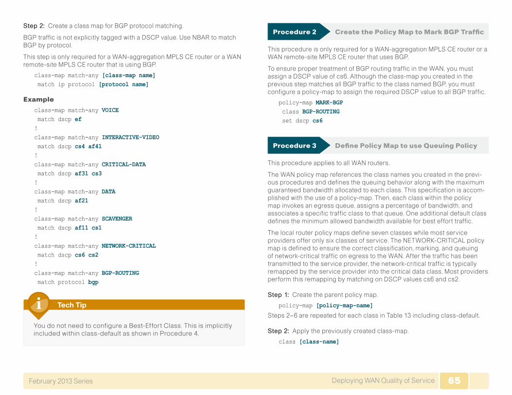
65Deploying WAN Quality of ServiceFebruary 2013 Series 65
Step 2: Create a class map for BGP protocol matching.
BGP traffic is not explicitly tagged with a DSCP value. Use NBAR to match BGP by protocol.
This step is only required for a WAN-aggregation MPLS CE router or a WAN remote-site MPLS CE router that is using BGP.
class-map match-any [class-map name] match ip protocol [protocol name]
Example
class-map match-any VOICE match dscp ef!class-map match-any INTERACTIVE-VIDEO match dscp cs4 af41!class-map match-any CRITICAL-DATA match dscp af31 cs3!class-map match-any DATA match dscp af21! class-map match-any SCAVENGER match dscp af11 cs1!class-map match-any NETWORK-CRITICAL match dscp cs6 cs2!class-map match-any BGP-ROUTING match protocol bgp
You do not need to configure a Best-Effort Class. This is implicitly included within class-default as shown in Procedure 4.
Tech Tip
Procedure 2 Create the Policy Map to Mark BGP Traffic
This procedure is only required for a WAN-aggregation MPLS CE router or a WAN remote-site MPLS CE router that uses BGP.
To ensure proper treatment of BGP routing traffic in the WAN, you must assign a DSCP value of cs6. Although the class-map you created in the previous step matches all BGP traffic to the class named BGP, you must configure a policy-map to assign the required DSCP value to all BGP traffic.
policy-map MARK-BGP class BGP-ROUTING set dscp cs6
Procedure 3 Define Policy Map to use Queuing Policy
This procedure applies to all WAN routers.
The WAN policy map references the class names you created in the previ-ous procedures and defines the queuing behavior along with the maximum guaranteed bandwidth allocated to each class. This specification is accom-plished with the use of a policy-map. Then, each class within the policy map invokes an egress queue, assigns a percentage of bandwidth, and associates a specific traffic class to that queue. One additional default class defines the minimum allowed bandwidth available for best effort traffic.
The local router policy maps define seven classes while most service providers offer only six classes of service. The NETWORK-CRITICAL policy map is defined to ensure the correct classification, marking, and queuing of network-critical traffic on egress to the WAN. After the traffic has been transmitted to the service provider, the network-critical traffic is typically remapped by the service provider into the critical data class. Most providers perform this remapping by matching on DSCP values cs6 and cs2.
Step 1: Create the parent policy map.
policy-map [policy-map-name]
Steps 2–6 are repeated for each class in Table 13 including class-default.
Step 2: Apply the previously created class-map.
class [class-name]
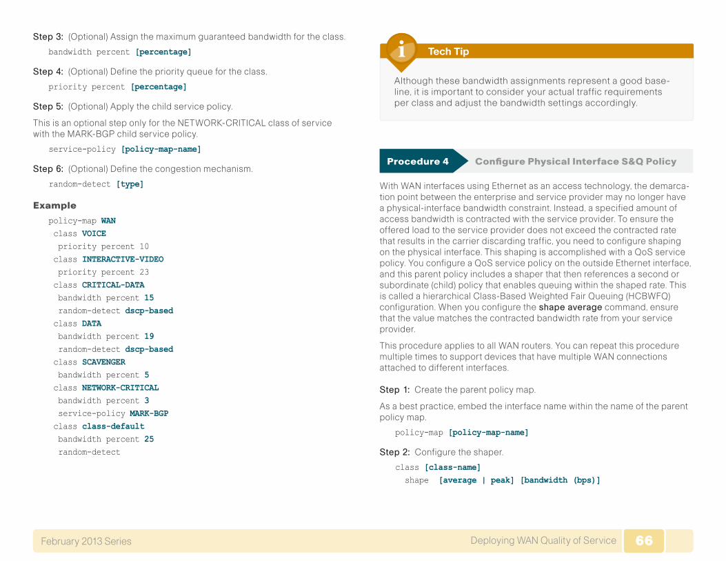
66Deploying WAN Quality of ServiceFebruary 2013 Series 66
Step 3: (Optional) Assign the maximum guaranteed bandwidth for the class.
bandwidth percent [percentage]
Step 4: (Optional) Define the priority queue for the class.
priority percent [percentage]
Step 5: (Optional) Apply the child service policy.
This is an optional step only for the NETWORK-CRITICAL class of service with the MARK-BGP child service policy.
service-policy [policy-map-name]
Step 6: (Optional) Define the congestion mechanism.
random-detect [type]
Example
policy-map WAN class VOICE priority percent 10 class INTERACTIVE-VIDEO priority percent 23 class CRITICAL-DATA bandwidth percent 15 random-detect dscp-based class DATA bandwidth percent 19 random-detect dscp-based class SCAVENGER bandwidth percent 5 class NETWORK-CRITICAL bandwidth percent 3 service-policy MARK-BGP class class-default bandwidth percent 25 random-detect
Although these bandwidth assignments represent a good base-line, it is important to consider your actual traffic requirements per class and adjust the bandwidth settings accordingly.
Tech Tip
Procedure 4 Configure Physical Interface S&Q Policy
With WAN interfaces using Ethernet as an access technology, the demarca-tion point between the enterprise and service provider may no longer have a physical-interface bandwidth constraint. Instead, a specified amount of access bandwidth is contracted with the service provider. To ensure the offered load to the service provider does not exceed the contracted rate that results in the carrier discarding traffic, you need to configure shaping on the physical interface. This shaping is accomplished with a QoS service policy. You configure a QoS service policy on the outside Ethernet interface, and this parent policy includes a shaper that then references a second or subordinate (child) policy that enables queuing within the shaped rate. This is called a hierarchical Class-Based Weighted Fair Queuing (HCBWFQ) configuration. When you configure theshapeaverage command, ensure that the value matches the contracted bandwidth rate from your service provider.
This procedure applies to all WAN routers. You can repeat this procedure multiple times to support devices that have multiple WAN connections attached to different interfaces.
Step 1: Create the parent policy map.
As a best practice, embed the interface name within the name of the parent policy map.
policy-map [policy-map-name]
Step 2: Configure the shaper.
class [class-name] shape [average | peak] [bandwidth (bps)]
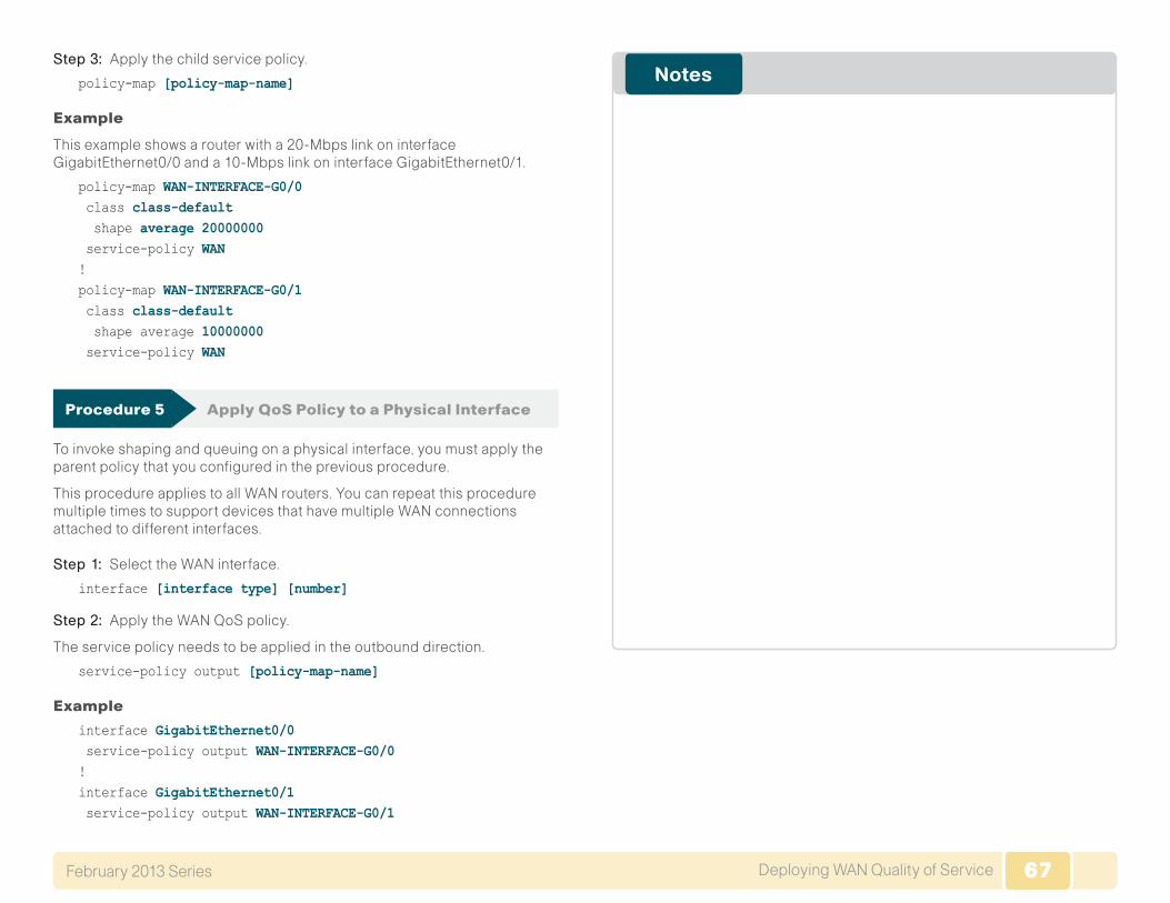
67Deploying WAN Quality of ServiceFebruary 2013 Series 67
Step 3: Apply the child service policy.
policy-map [policy-map-name]
Example
This example shows a router with a 20-Mbps link on interface GigabitEthernet0/0 and a 10-Mbps link on interface GigabitEthernet0/1.
policy-map WAN-INTERFACE-G0/0 class class-default shape average 20000000 service-policy WAN!policy-map WAN-INTERFACE-G0/1 class class-default shape average 10000000 service-policy WAN
Procedure 5 Apply QoS Policy to a Physical Interface
To invoke shaping and queuing on a physical interface, you must apply the parent policy that you configured in the previous procedure.
This procedure applies to all WAN routers. You can repeat this procedure multiple times to support devices that have multiple WAN connections attached to different interfaces.
Step 1: Select the WAN interface.
interface [interface type] [number]
Step 2: Apply the WAN QoS policy.
The service policy needs to be applied in the outbound direction.
service-policy output [policy-map-name]
Example
interface GigabitEthernet0/0 service-policy output WAN-INTERFACE-G0/0!interface GigabitEthernet0/1 service-policy output WAN-INTERFACE-G0/1
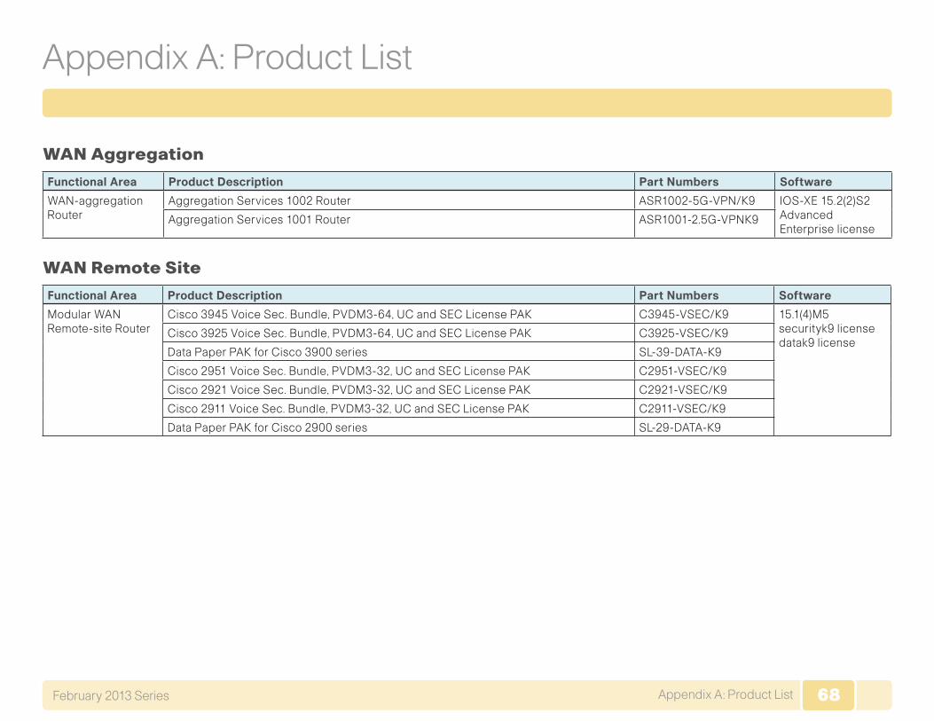
68Appendix A: Product ListFebruary 2013 Series 68
Appendix A: Product List
WAN Aggregation
Functional Area Product Description Part Numbers Software
WAN-aggregation Router
Aggregation Services 1002 Router ASR1002-5G-VPN/K9 IOS-XE 15.2(2)S2 Advanced Enterprise license
Aggregation Services 1001 Router ASR1001-2.5G-VPNK9
WAN Remote Site
Functional Area Product Description Part Numbers Software
Modular WAN Remote-site Router
Cisco 3945 Voice Sec. Bundle, PVDM3-64, UC and SEC License PAK C3945-VSEC/K9 15.1(4)M5 securityk9 license datak9 license
Cisco 3925 Voice Sec. Bundle, PVDM3-64, UC and SEC License PAK C3925-VSEC/K9
Data Paper PAK for Cisco 3900 series SL-39-DATA-K9
Cisco 2951 Voice Sec. Bundle, PVDM3-32, UC and SEC License PAK C2951-VSEC/K9
Cisco 2921 Voice Sec. Bundle, PVDM3-32, UC and SEC License PAK C2921-VSEC/K9
Cisco 2911 Voice Sec. Bundle, PVDM3-32, UC and SEC License PAK C2911-VSEC/K9
Data Paper PAK for Cisco 2900 series SL-29-DATA-K9
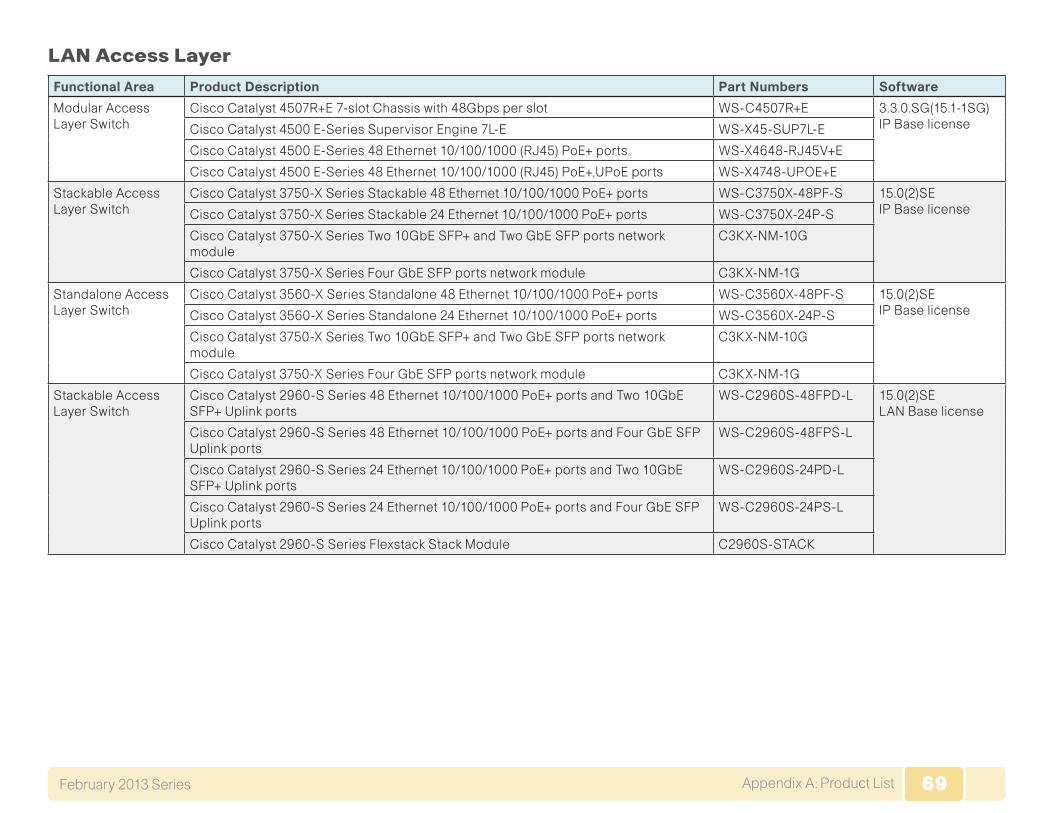
69Appendix A: Product ListFebruary 2013 Series 69
LAN Access Layer
Functional Area Product Description Part Numbers Software
Modular Access Layer Switch
Cisco Catalyst 4507R+E 7-slot Chassis with 48Gbps per slot WS-C4507R+E 3.3.0.SG(15.1-1SG) IP Base licenseCisco Catalyst 4500 E-Series Supervisor Engine 7L-E WS-X45-SUP7L-E
Cisco Catalyst 4500 E-Series 48 Ethernet 10/100/1000 (RJ45) PoE+ ports WS-X4648-RJ45V+E
Cisco Catalyst 4500 E-Series 48 Ethernet 10/100/1000 (RJ45) PoE+,UPoE ports WS-X4748-UPOE+E
Stackable Access Layer Switch
Cisco Catalyst 3750-X Series Stackable 48 Ethernet 10/100/1000 PoE+ ports WS-C3750X-48PF-S 15.0(2)SE IP Base licenseCisco Catalyst 3750-X Series Stackable 24 Ethernet 10/100/1000 PoE+ ports WS-C3750X-24P-S
Cisco Catalyst 3750-X Series Two 10GbE SFP+ and Two GbE SFP ports network module
C3KX-NM-10G
Cisco Catalyst 3750-X Series Four GbE SFP ports network module C3KX-NM-1G
Standalone Access Layer Switch
Cisco Catalyst 3560-X Series Standalone 48 Ethernet 10/100/1000 PoE+ ports WS-C3560X-48PF-S 15.0(2)SE IP Base licenseCisco Catalyst 3560-X Series Standalone 24 Ethernet 10/100/1000 PoE+ ports WS-C3560X-24P-S
Cisco Catalyst 3750-X Series Two 10GbE SFP+ and Two GbE SFP ports network module
C3KX-NM-10G
Cisco Catalyst 3750-X Series Four GbE SFP ports network module C3KX-NM-1G
Stackable Access Layer Switch
Cisco Catalyst 2960-S Series 48 Ethernet 10/100/1000 PoE+ ports and Two 10GbE SFP+ Uplink ports
WS-C2960S-48FPD-L 15.0(2)SE LAN Base license
Cisco Catalyst 2960-S Series 48 Ethernet 10/100/1000 PoE+ ports and Four GbE SFP Uplink ports
WS-C2960S-48FPS-L
Cisco Catalyst 2960-S Series 24 Ethernet 10/100/1000 PoE+ ports and Two 10GbE SFP+ Uplink ports
WS-C2960S-24PD-L
Cisco Catalyst 2960-S Series 24 Ethernet 10/100/1000 PoE+ ports and Four GbE SFP Uplink ports
WS-C2960S-24PS-L
Cisco Catalyst 2960-S Series Flexstack Stack Module C2960S-STACK
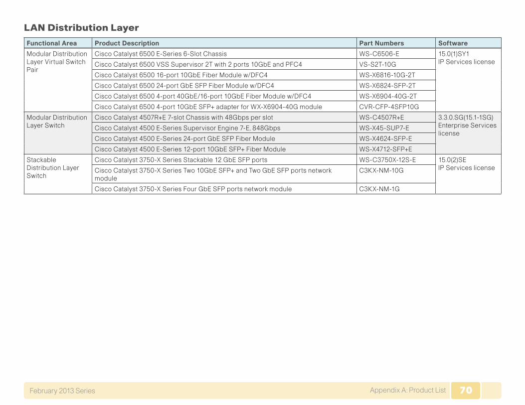
70Appendix A: Product ListFebruary 2013 Series 70
LAN Distribution Layer
Functional Area Product Description Part Numbers Software
Modular Distribution Layer Virtual Switch Pair
Cisco Catalyst 6500 E-Series 6-Slot Chassis WS-C6506-E 15.0(1)SY1 IP Services licenseCisco Catalyst 6500 VSS Supervisor 2T with 2 ports 10GbE and PFC4 VS-S2T-10G
Cisco Catalyst 6500 16-port 10GbE Fiber Module w/DFC4 WS-X6816-10G-2T
Cisco Catalyst 6500 24-port GbE SFP Fiber Module w/DFC4 WS-X6824-SFP-2T
Cisco Catalyst 6500 4-port 40GbE/16-port 10GbE Fiber Module w/DFC4 WS-X6904-40G-2T
Cisco Catalyst 6500 4-port 10GbE SFP+ adapter for WX-X6904-40G module CVR-CFP-4SFP10G
Modular Distribution Layer Switch
Cisco Catalyst 4507R+E 7-slot Chassis with 48Gbps per slot WS-C4507R+E 3.3.0.SG(15.1-1SG) Enterprise Services license
Cisco Catalyst 4500 E-Series Supervisor Engine 7-E, 848Gbps WS-X45-SUP7-E
Cisco Catalyst 4500 E-Series 24-port GbE SFP Fiber Module WS-X4624-SFP-E
Cisco Catalyst 4500 E-Series 12-port 10GbE SFP+ Fiber Module WS-X4712-SFP+E
Stackable Distribution Layer Switch
Cisco Catalyst 3750-X Series Stackable 12 GbE SFP ports WS-C3750X-12S-E 15.0(2)SE IP Services licenseCisco Catalyst 3750-X Series Two 10GbE SFP+ and Two GbE SFP ports network
moduleC3KX-NM-10G
Cisco Catalyst 3750-X Series Four GbE SFP ports network module C3KX-NM-1G
71Appendix B: Changes February 2013 Series 71
Appendix B: Changes
This appendix summarizes the changes to this guide since the previous Cisco SBA series.
• We made changes to improve the readability and technical accuracy of this guide.
• We updated the code version for the Cisco ASR and ISR platforms.
ALL DESIGNS, SPECIFICATIONS, STATEMENTS, INFORMATION, AND RECOMMENDATIONS (COLLECTIVELY, “DESIGNS”) IN THIS MANUAL ARE PRESENTED “AS IS,” WITH ALL FAULTS. CISCO AND ITS SUPPLiERS DISCLAIM ALL WARRANTIES, INCLUDING, WITH-OUT LIMITATION, THE WARRANTY OF MERCHANTABILITY, FITNESS FOR A PARTICULAR PURPOSE AND NONINFRINGEMENT OR ARISING FROM A COURSE OF DEALING, USAGE, OR TRADE PRACTICE. IN NO EVENT SHALL CISCO OR ITS SUPPLIERS BE LIABLE FOR ANY INDIRECT, SPECIAL, CONSEQUENTIAL, OR INCIDENTAL DAMAGES, INCLUDING, WITHOUT LIMITATION, LOST PROFITS OR LOSS OR DAMAGE TO DATA ARISING OUT OF THE USE OR INABILITY TO USE THE DESIGNS, EVEN IF CISCO OR ITS SUPPLIERS HAVE BEEN ADVISED OF THE POSSIBILITY OF SUCH DAMAGES. THE DESIGNS ARE SUBJECT TO CHANGE WITHOUT NOTICE. USERS ARE SOLELY RESPONSIBLE FOR THEIR APPLICATION OF THE DESIGNS. THE DESIGNS DO NOT CONSTITUTE THE TECHNICAL OR OTHER PROFESSIONAL ADVICE OF CISCO, ITS SUPPLIERS OR PARTNERS. USERS SHOULD CONSULT THEIR OWN TECHNICAL ADVISORS BEFORE IMPLEMENTING THE DESIGNS. RESULTS MAY VARY DEPENDING ON FACTORS NOT TESTED BY CISCO.
Any Internet Protocol (IP) addresses used in this document are not intended to be actual addresses. Any examples, command display output, and figures included in the document are shown for illustrative purposes only. Any use of actual IP addresses in illustrative content is unintentional and coincidental.
© 2013 Cisco Systems, Inc. All rights reserved.
Cisco and the Cisco logo are trademarks or registered trademarks of Cisco and/or its affiliates in the U.S. and other countries. To view a list of Cisco trademarks, go to this URL: www.cisco.com/go/trademarks. Third-party trademarks mentioned are the property of their respective owners. The use of the word partner does not imply a partnership relationship between Cisco and any other company. (1110R)
Please use the feedback form to send comments and suggestions about this guide.
Feedback
SMART BUSINESS ARCHITECTURE
Americas HeadquartersCisco Systems, Inc.San Jose, CA
Asia Pacific HeadquartersCisco Systems (USA) Pte. Ltd.Singapore
Europe HeadquartersCisco Systems International BV Amsterdam,The Netherlands
Cisco has more than 200 offices worldwide. Addresses, phone numbers, and fax numbers are listed on the Cisco Website at www.cisco.com/go/offices.
B-0000245-1 1/13