cisco mds 9000 family i/o accelerator …...in-1 cisco mds 9000 family i/o accelerator configuration...
TRANSCRIPT
Cisco MOL-27639-01, Cisco MDS NX-OS Release 5.2(6)
I N D E X
C
Cisco SME
required engines B-5
clusters
quorum B-1
reviving B-8
D
documentation
additional publications iv-xiv
M
master switch election B-1
four-switch cluster scenarios B-4
three-switch cluster scenarios B-3
R
related documents iv-xiv
S
Single-fabric Topology B-5
SME
supported single-fabric topology B-5
supported topologies
single-fabric B-5
T
troubleshooting
deleting a cluster B-6, B-7
deleting an offline switch B-5
reviving a cluster B-8
IN-1DS 9000 Family I/O Accelerator Configuration Guide

Index
IN-2Cisco MDS 9000 Family I/O Accelerator Configuration Guide
OL-27639-01, Cisco MDS NX-OS Release 5.2(6)
New and Changed Information
This document provides release-specific information for each new and changed feature for Cisco I/O Accelerator. The Cisco MDS 9000 Family I/O Accelerator Configuration Guide applies to Cisco NX-OS Release 4.2(1) and later.
To check for additional information about this release and to determine if this release supports I/O Accelerator, refer to the Cisco MDS 9000 Family Release Notes and Cisco Cisco DCNM-SAN Release Notes available at the following Cisco Systems website:
http://www.cisco.com/en/US/products/ps5989/prod_release_notes_list.html
Table 1-1 summarizes the new and changed features as described in the Cisco MDS 9000 Family I/O Accelerator Configuration Guide, each supported NX-OS release for the Cisco MDS 9500 Series, with the latest release first. The table includes a brief description of each new feature and the release in which the change occurred.
Table 1-1 New and Changed Features for Cisco I/O Accelerator
Feature Description
Changed in Release Where Documented
JPMC enhancements Added show ioa online flows interface commands.
5.2(6) Chapter 4, “Configuring IOA Using the CLI”
ISAPI enhancements Added information about ISAPI enhancements.
5.0(1a) Chapter 4, “Configuring IOA Using the CLI”
IOA is supported with IVR
Added IVR flows support with IOA 5.0(1a) Chapter 3, “Deployment Considerations”
-1Cisco MDS 9000 Family I/O Accelerator Configuration Guide
OL-27639-01, Cisco MDS NX-OS Release 5.2(6)

-2Cisco MDS 9000 Family I/O Accelerator Configuration Guide
OL-20708-01
Send documenta t i on comments to dcnm-san -doc feedback@c i sco . com
Preface
This preface describes the audience, organization, and conventions of the Cisco MDS 9000 Family I/O Accelerator Configuration Guide. The preface also provides information on how to obtain related documentation.
AudienceThis guide is for experienced network administrators who are responsible for planning, installing, configuring, and maintaining the Cisco MDS 9000 Family I/O Accelerator (IOA) feature.
OrganizationThis document is organized as follows:
Chapter Title Description
Chapter 1 Overview Presents an overview of the Cisco MDS I/O Accelerator feature and the software and hardware requirements.
Chapter 2 Getting Started Describes the various configurations that need to be completed before configuring IOA.
Chapter 3 Deployment Considerations Describes the various deployment scenarios and considerations.
Chapter 4 Configuring IOA Using the CLI Describes how to use IOA CLI commands to configure and monitor Cisco IOA clusters.
Chapter 5 Configuring IOA Using Cisco DCNM-SAN
Describes how to use Cisco DCNM-SAN to configure and monitor Cisco IOA clusters.
Chapter 6 SCSI Write Acceleration and Tape Acceleration
Describes the concept of SCSI write acceleration, tape acceleration, and compression.
Appendix 1 Cluster Management and Recovery Scenarios
Describes the cluster management guidelines and cluster recovery procedures.
1Cisco MDS 9000 Family I/O Accelerator Configuration Guide
OL-27639-01, Cisco MDS NX-OS Release 5.2(6)
Send documenta t i on comments to dcnm-san -doc feedback@c i sco . com
Preface
Document ConventionsCommand descriptions use these conventions:
boldface font Commands and keywords are in boldface.
italic font Arguments for which you supply values are in italics.
[ ] Elements in square brackets are optional.
[ x | y | z ] Optional alternative keywords are grouped in brackets and separated by vertical bars.
Screen examples use these conventions:
screen font Terminal sessions and information the switch displays are in screen font.
boldface screen font Information you must enter is in boldface screen font.
italic screen font Arguments for which you supply values are in italic screen font.
< > Nonprinting characters, such as passwords, are in angle brackets.
[ ] Default responses to system prompts are in square brackets.
!, # An exclamation point (!) or a pound sign (#) at the beginning of a line of code indicates a comment line.
This document uses the following conventions:
Note Means reader take note. Notes contain helpful suggestions or references to material not covered in the manual.
Caution Means reader be careful. In this situation, you might do something that could result in equipment damage or loss of data.
Related DocumentationThis section contains information about the documentation available for Cisco DCNM and for the platforms that Cisco DCNM manages.
This section includes the following topics:
• Cisco DCNM Documentation, page 3
• Cisco Nexus 1000V Series Switch Documentation, page 4
• Cisco Nexus 2000 Series Fabric Extender Documentation, page 4
• Cisco Nexus 3000 Series Switch Documentation, page 4
• Cisco Nexus 4000 Series Switch Documentation, page 4
• Cisco Nexus 5000 Series Switch Documentation, page 4
• Cisco Nexus 7000 Series Switch Documentation, page 4
2Cisco MDS 9000 Family I/O Accelerator Configuration Guide
OL-27639-01, Cisco MDS NX-OS Release 5.2(6)
Send documenta t i on comments to dcnm-san -doc feedback@c i sco . com
Preface
Cisco DCNM DocumentationThe Cisco DCNM documentation is available at the following URL:
http://www.cisco.com/en/US/products/ps9369/tsd_products_support_series_home.html
The documentation set for Cisco DCNM includes the following documents:
Release Notes
Cisco DCNM Release Notes, Release 6.x
Installation and Licensing
Cisco DCNM Installation and Licensing Guide, Release 6.x
Cisco DCNM Fundamentals Guide
Cisco DCNM Fundamentals Guide, Release 6.x
Cisco DCNM for LAN Configuration Guides
FabricPath Configuration Guide, Cisco DCNM for LAN, Release 6.x
Interfaces Configuration Guide, Cisco DCNM for LAN, Release 6.x
Layer 2 Switching Configuration Guide, Cisco DCNM for LAN, Release 6.x
Security Configuration Guide, Cisco DCNM for LAN, Release 6.x
System Management Configuration Guide, Cisco DCNM for LAN, Release 6.x
Unicast Configuration Guide, Cisco DCNM for LAN, Release 6.x
Virtual Device Context Configuration Guide, Cisco DCNM for LAN, Release 6.x
Virtual Device Context Quick Start, Cisco DCNM for LAN, Release 6.x
Web Services API Guide, Cisco DCNM for LAN, Release 6.x
Cisco DCNM for SAN Configuration Guides
System Management Configuration Guide, Cisco DCNM for SAN, Release 6.x
Interfaces Configuration Guide, Cisco DCNM for SAN, Release 6.x
Fabric Configuration Guide, Cisco DCNM for SAN, Release 6.x
Quality of Service Configuration Guide, Cisco DCNM for SAN, Release 6.x
Security Configuration Guide, Cisco DCNM for SAN, Release 6.x
IP Services Configuration Guide, Cisco DCNM for SAN, Release 6.x
Intelligent Storage Services Configuration Guide, Cisco DCNM for SAN, Release 6.x
High Availability and Redundancy Configuration Guide, Cisco DCNM for SAN, Release 6.x
Inter-VSAN Routing Configuration Guide, Cisco DCNM for SAN, Release 6.x
SMI-S and Web Services Programming Guide, Cisco DCNM for SAN, Release 6.x
SME Configuration Guide, Cisco DCNM for SAN, Release 6.x
3Cisco MDS 9000 Family I/O Accelerator Configuration Guide
OL-27639-01, Cisco MDS NX-OS Release 5.2(6)
Send documenta t i on comments to dcnm-san -doc feedback@c i sco . com
Preface
Cisco Nexus 1000V Series Switch DocumentationThe Cisco Nexus 1000V Series switch documentation is available at the following URL:
http://www.cisco.com/en/US/products/ps9902/tsd_products_support_series_home.html
Cisco Nexus 2000 Series Fabric Extender DocumentationThe Cisco Nexus 2000 Series Fabric Extender documentation is available at the following URL:
http://www.cisco.com/en/US/products/ps10110/tsd_products_support_series_home.html
Cisco Nexus 3000 Series Switch DocumentationThe Cisco Nexus 3000 Series switch documentation is available at the followingURL:
http://www.cisco.com/en/US/products/ps11541/tsd_products_support_series_home.html
Cisco Nexus 4000 Series Switch DocumentationThe Cisco Nexus 4000 Series switch documentation is available at the following URL:
http://www.cisco.com/en/US/products/ps10596/tsd_products_support_series_home.html
Cisco Nexus 5000 Series Switch DocumentationThe Cisco Nexus 5000 Series switch documentation is available at the following URL:
http://www.cisco.com/en/US/products/ps9670/tsd_products_support_series_home.html
Cisco Nexus 7000 Series Switch DocumentationThe Cisco Nexus 7000 Series switch documentation is available at the following URL:
http://www.cisco.com/en/US/products/ps9902/tsd_products_support_series_home.html
Additional Related Documentation for Cisco MDS 9000The documentation set for the Cisco MDS 9000 Family includes the following documents. To find a document online, use the Cisco MDS NX-OS Documentation Locator at:
http://www.cisco.com/en/US/docs/storage/san_switches/mds9000/roadmaps/doclocater.htm
Release Notes • Cisco MDS 9000 Family Release Notes for Cisco MDS NX-OS Releases
• Cisco MDS 9000 Family Release Notes for MDS SAN-OS Releases
4Cisco MDS 9000 Family I/O Accelerator Configuration Guide
OL-27639-01, Cisco MDS NX-OS Release 5.2(6)
Send documenta t i on comments to dcnm-san -doc feedback@c i sco . com
Preface
• Cisco MDS 9000 Family Release Notes for Cisco MDS 9000 EPLD Images
Regulatory Compliance and Safety Information • Regulatory Compliance and Safety Information for the Cisco MDS 9000 Family
Compatibility Information • Cisco Data Center Interoperability Support Matrix
• Cisco MDS 9000 NX-OS Hardware and Software Compatibility Information and Feature Lists
• Cisco MDS 9000 Family Switch-to-Switch Interoperability Configuration Guide
Hardware Installation • Cisco MDS 9500 Series Hardware Installation Guide
• Cisco MDS 9200 Series Hardware Installation Guide
• Cisco MDS 9100 Series Hardware Installation Guide
• Cisco MDS 9124 and Cisco MDS 9134 Multilayer Fabric Switch Quick Start Guide
Software Installation and Upgrade • Cisco MDS 9000 NX-OS Software Upgrade and Downgrade Guide
Cisco NX-OS • Cisco MDS 9000 Family NX-OS Licensing Guide
• Cisco MDS 9000 Family NX-OS Fundamentals Configuration Guide
• Cisco MDS 9000 Family NX-OS System Management Configuration Guide
• Cisco MDS 9000 Family NX-OS Interfaces Configuration Guide
• Cisco MDS 9000 Family NX-OS Fabric Configuration Guide
• Cisco MDS 9000 Family NX-OS Quality of Service Configuration Guide
• Cisco MDS 9000 Family NX-OS Security Configuration Guide
• Cisco MDS 9000 Family NX-OS IP Services Configuration Guide
• Cisco MDS 9000 Family NX-OS Intelligent Storage Services Configuration Guide
• Cisco MDS 9000 Family NX-OS High Availability and Redundancy Configuration Guide
• Cisco MDS 9000 Family NX-OS Inter-VSAN Routing Configuration Guide
• Cisco MDS 9000 Family Cookbook for Cisco MDS SAN-OS
5Cisco MDS 9000 Family I/O Accelerator Configuration Guide
OL-27639-01, Cisco MDS NX-OS Release 5.2(6)
Send documenta t i on comments to dcnm-san -doc feedback@c i sco . com
Preface
Command-Line Interface • Cisco MDS 9000 Family Command Reference
Intelligent Storage Networking Services Configuration Guides • Cisco MDS 9000 Family I/O Acceleration Configuration Guide
• Cisco MDS 9000 Family SANTap Deployment Guide
• Cisco MDS 9000 Family Data Mobility Manager Configuration Guide
• Cisco MDS 9000 Family Storage Media Encryption Configuration Guide
Troubleshooting and Reference • Cisco MDS 9000 Family and Nexus 7000 Series System Messages Reference
• Cisco MDS 9000 Family SAN-OS Troubleshooting Guide
• Cisco MDS 9000 Family NX-OS MIB Quick Reference
• Cisco DCNM for SAN Database Schema Reference
Obtaining Documentation and Submitting a Service RequestFor information on obtaining documentation, submitting a service request, and gathering additional information, see the monthly What’s New in Cisco Product Documentation, which also lists all new and revised Cisco technical documentation, at:
http://www.cisco.com/en/US/docs/general/whatsnew/whatsnew.html
Subscribe to the What’s New in Cisco Product Documentation as a Really Simple Syndication (RSS) feed and set content to be delivered directly to your desktop using a reader application. The RSS feeds are a free service and Cisco currently supports RSS version 2.0.
6Cisco MDS 9000 Family I/O Accelerator Configuration Guide
OL-27639-01, Cisco MDS NX-OS Release 5.2(6)
Cisco MOL-27639-01, Cisco MDS NX-OS Release 5.2(6)
C H A P T E R 1
OverviewThis chapter provides an overview of the Cisco I/O Accelerator feature and includes the following sections:
• About Cisco I/O Accelerator, page 1-1
• Example IOA Topology, page 1-3
• Terminology, page 1-3
• Hardware Requirements, page 1-5
• Software Requirements, page 1-5
• License Requirements, page 1-6
About Cisco I/O AcceleratorThe Cisco MDS 9000 Family I/O Accelerator (IOA) feature provides Small Computer System Interface (SCSI) acceleration in a storage area network (SAN) where the sites are interconnected over long distances using Fibre Channel or Fibre Channel over IP (FCIP) Inter-Switch Links (ISLs).
IOA provides these features, which are described in the following sections:
• Unified Acceleration Service, page 1-1
• Topology Independent, page 1-2
• Transport Agnostic, page 1-2
• High Availability and Resiliency, page 1-2
• Improved Tape Acceleration Performance, page 1-2
• Load Balancing, page 1-2
Unified Acceleration ServiceIOA provides both SCSI write acceleration and tape acceleration features as a unified fabric service. These services were provided in previous releases in the form of Fibre Channel write acceleration for remote replication over Fibre Channel links and FCIP write acceleration and tape acceleration over FCIP links. Fibre Channel write acceleration was offered on the Storage Services Module (SSM) and FCIP write acceleration and tape acceleration were offered on the IP storage services modules. IOA offers both
1-1DS 9000 Family I/O Accelerator Configuration Guide
Chapter 1 Overview About Cisco I/O Accelerator
the write acceleration and tape acceleration services on the Cisco MDS MSM-18/4 module, SSN-16 module, and 9222i switch as a fabric service. This eliminates the need to buy separate hardware to obtain Fibre Channel write acceleration and FCIP write acceleration and tape acceleration.
Topology IndependentIOA can be deployed anywhere in the fabric without rewiring the hardware or reconfiguring the fabric. There are no restrictions on where the hosts and targets are connected to. Both the Fibre Channel and FCIP write acceleration is supported only on PortChannels but do not support multiple equal-cost links. FCIP tape acceleration is not supported on PortChannels. IOA eliminates these topological restrictions.
Transport AgnosticIOA is completely transport-agnostic and is supported on both Fibre Channel and FCIP ISLs between two sites.
High Availability and ResiliencyIOA equally supports both PortChannels and equal-cost multiple path (ECMP) links across two data centers. This allows you to seamlessly add ISLs across the two data centers for capacity building or redundancy. IOA is completely resilient against ISL failures. IOA uses a Lightweight Reliable Transport Protocol (LRTP) to guard against any ISL failures as long as there is an alternate path available across the two data centers. Remote replication and tape backup applications are completely unaffected by these failures.
Improved Tape Acceleration PerformanceIOA tape acceleration provides higher throughput numbers than the FCIP tape acceleration, which is limited by a single Gigabit Ethernet throughput.
Load BalancingIOA uses clustering technology to provide automatic load balancing and redundancy for traffic flows across multiple IOA service engines that can be configured for the IOA service. When an IOA service engine fails, the affected traffic flows are automatically redirected to the available IOA service engines to resume acceleration.
1-2Cisco MDS 9000 Family I/O Accelerator Configuration Guide
OL-27639-01, Cisco MDS NX-OS Release 5.2(6)
Chapter 1 OverviewExample IOA Topology
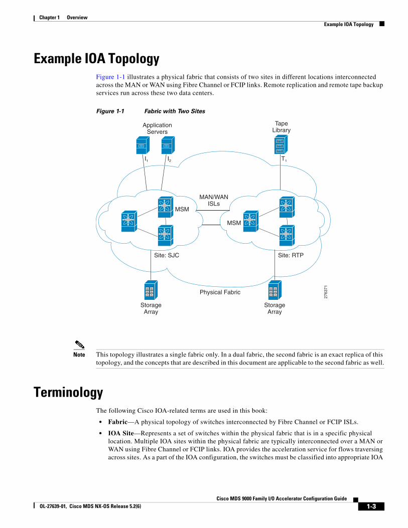
Example IOA TopologyFigure 1-1 illustrates a physical fabric that consists of two sites in different locations interconnected across the MAN or WAN using Fibre Channel or FCIP links. Remote replication and remote tape backup services run across these two data centers.
Figure 1-1 Fabric with Two Sites
ApplicationServers
TapeLibrary
2763
71
MAN/WANISLs
Site: SJC Site: RTP
Physical Fabric
StorageArray
StorageArray
I1 I2 T1
MSM
MSM
Note This topology illustrates a single fabric only. In a dual fabric, the second fabric is an exact replica of this topology, and the concepts that are described in this document are applicable to the second fabric as well.
TerminologyThe following Cisco IOA-related terms are used in this book:
• Fabric—A physical topology of switches interconnected by Fibre Channel or FCIP ISLs.
• IOA Site—Represents a set of switches within the physical fabric that is in a specific physical location. Multiple IOA sites within the physical fabric are typically interconnected over a MAN or WAN using Fibre Channel or FCIP links. IOA provides the acceleration service for flows traversing across sites. As a part of the IOA configuration, the switches must be classified into appropriate IOA
1-3Cisco MDS 9000 Family I/O Accelerator Configuration Guide
OL-27639-01, Cisco MDS NX-OS Release 5.2(6)
Chapter 1 Overview Terminology
sites. Acceleration is provided for flows traversing the MAN or WAN across sites. The main reason to classify the sites is to select the intersite flows for acceleration. No intrasite flows will be allowed to participate in acceleration.
Note When using the CLI, only the switches where IOA is deployed need to be classified into a site. When using the Cisco DCNM-SAN, all the switches in a physical location need to be classified into a site. The site classification is used internally by the Cisco DCNM-SAN to automate the classification of the flows that traverse across sites.
• IOA Interface—Represents a single service engine in the MSM-18/4 Module or the SSN-16 Module. An IOA interface must be provisioined to enable IOA service on the service engine. The MSM-18/4 Module has one service engine and the SSN-16 Module has four service engines, which directly represents the number of IOA interfaces that can be created on these modules. In the CLI, an IOA interface is represented as interface ioa x/y where x represents the slot and y represents the service engine ID. With the SSN-16, the service engine ID can be 1 to 4. Each IOA interface requires a IOA license to be checked out.
An IOA interface must be brought up administratively to enable the IOA service on the service engine.
• IOA Switch—Represents a switch that has one or more IOA Interfaces configured for the IOA service. The terms IOA switch and IOA node are used interchangeably in this configuration guide.
• IOA Cluster—A set of IOA switches that can operate in a coordinated manner to provide the IOA service. An IOA cluster can only span two IOA sites. If there is a consolidation site that has connectivity to various other sites, each site pair must be represented by a unique IOA cluster. A switch may participate in multiple IOA clusters due to this reason, but each IOA interface is bound only to one IOA cluster. This architecture allows for cluster scalability and limiting the scope of configuration distribution as appropriate.
• IOA N Port—Represents a Fibre Channel N port represented by a port world-wide name. IOA requires that the site to which the N port belongs and the VSAN ID be configured. The site classification is required to identify how to redirect the traffic flow for acceleration.
• FC-Redirect —Fibre Channel Redirect (FC-Redirect) infrastructure provides the ability to redirect a flow to a specific service engine in the fabric to provide certain intelligent services such as Storage Media Encryption and Data Mobility Manager. This infrastructure has been extended for IOA to redirect the flow to two service engines in the fabric that can then work together to provide the acceleration intelligence.
Both the host and the target or tape must be directly attached to a FC-Redirect-capable switch.
• IOA Flow—A flow that is accelerated across the MAN or WAN by the IOA cluster. Each IOA flow is identified by initiator PWWN and target PWWN.
IOA provide bidirectional acceleration for each configured flow. A separate reverse flow configuration is not required.
• IOA Flow Group—A set of IOA flows classified for a specific purpose. For example, if the same IOA cluster is being used for remote replication and backup, you can have all the replication flows classified into the replication flow group and all the backup flows classified into the backup flow group.
1-4Cisco MDS 9000 Family I/O Accelerator Configuration Guide
OL-27639-01, Cisco MDS NX-OS Release 5.2(6)
Chapter 1 OverviewClustering
Note You can have more than one IOA service engine in the same site in the IOA cluster. In fact, this is the preferred configuration wherein if an IOA service engine fails , then all the flows bound to it can be automatically moved to another available IOA service engine in the same site. This is taken care of by the IOA cluster based load balancer.
ClusteringIOA is offered as a clustered service that consists of a set of switches that operates in coordination with each other. Clustering provides the following advantages:
• Single point management— IOA can be managed as a fabric service from a single switch. You need not configure multiple switches individually to provide IOA as a fabric service.
• Automatic load-balancing— You can provision all of the flows that need to be accelerated through IOA. Clustering allows these flows to load-balance automatically across all the available IOA service engines within the cluster. It also makes it easy to plan for capacity as you just need to add an additional IOA service engine when there is a need to add more throughput within IOA.
• Resiliency— Allows automatic failover of the IOA flows whenever an IOA service engine fails on any of the switches. If a switch fails, an alternate switch in the cluster takes over the failed flows to maintain the contiuity of the IOA service.
IOA clustering uses standard algorithms to provide consistency and reliability of the configuration metadata required for the service to be operational. A master switch is internally elected by the clustering infrastructure to perform certain tasks such as load-balancing and failover. To keep the process simple, we recommend that you provision the IOA from the master switch. If the network fails, which partitions the switches in a cluster, a standard majority node-based quorum algorithm is used to decide which partition should be operational to be able to guarantee the consistency.
An internal node ID that is allocated as a part of adding the switches to the cluster is used in the master election algorithm. If you intend to manage IOA from a specific switch or a site, we recommend that you use this switch as a seed switch when a IOA cluster is configured, and also add all the nodes in this site before you add the nodes from the remote site into the IOA cluster.
Hardware RequirementsIOA is supported on the Cisco MDS 9000 Family 18/4-port Multiservice (MSM-18/4) Module, the Cisco MDS 9222i Switch, and the 16-Port Storage Services Node (SSN-16) module. Each MSM-18/4 Module and 9222i Switch has one service engine that can be configured for the Cisco IOA service. The SSN-16 module has four service engines that can be used for the IOA service.
Software RequirementsTo enable IOA feature on the MSM-18/4 Module or SSN-16 Module, the MDS 9000 Family switch must run Cisco NX-OS Release 4.2(1) or later. You must also use Cisco DCNM-SAN 5.2(1) to manage the switches. Hosts must be connected to a switch running Cisco SAN-OS 3.3(1c) or later. Targets must be connected to a switch running Cisco NX-OS Release 4.2(1) or later.
1-5Cisco MDS 9000 Family I/O Accelerator Configuration Guide
OL-27639-01, Cisco MDS NX-OS Release 5.2(6)
Chapter 1 Overview License Requirements
License RequirementsThe Cisco MDS 9000 Family IOA package is licensed per service engine and is tied to the chassis. The number of licenses required is equal to the number of service engines on which the intelligent fabric application is used.
IOA runs on the MDS 9222i Switch (native) and on the MSM-18/4 Module and SSN-16 Module. The modules are supported in the MDS 9500 Directors and the MDS 9222i Switch.
On the SSN-16 Module, a separate license is required for each engine that will run IOA. Each SSN-16 engine configured for IOA checks out a license from the pool managed at the chassis level. For convenience, SSN-16 Module licenses can be purchased singly (the usual model) or in a package of four. Once they are installed into an MDS 9000 chassis, there is no difference between the IOA package of four and four single IOA licenses.
On the SSN-16 Module, because each engine is licensed independently, different licensed features can be configured on the four engines based on the following requirements for NX-OS Release 4.2(1):
• As with the MDS 9222i Switch and the MSM-18/4 Module, only one licensed feature can run on an engine at a time.
• On the SSN-16 Module, mix and match is supported for IOA and SAN Extension over IP in any combination (4+0, 1+3, 2+2, 3+1, or 0+4).
• Storage Media Encryption (SME) is not supported for mix and match in NX-OS Release 4.2(1).
To use the IOA features, Cisco MDS NX-OS Release 4.2(1) or later must be installed on a Cisco MDS 9000 Family switch.
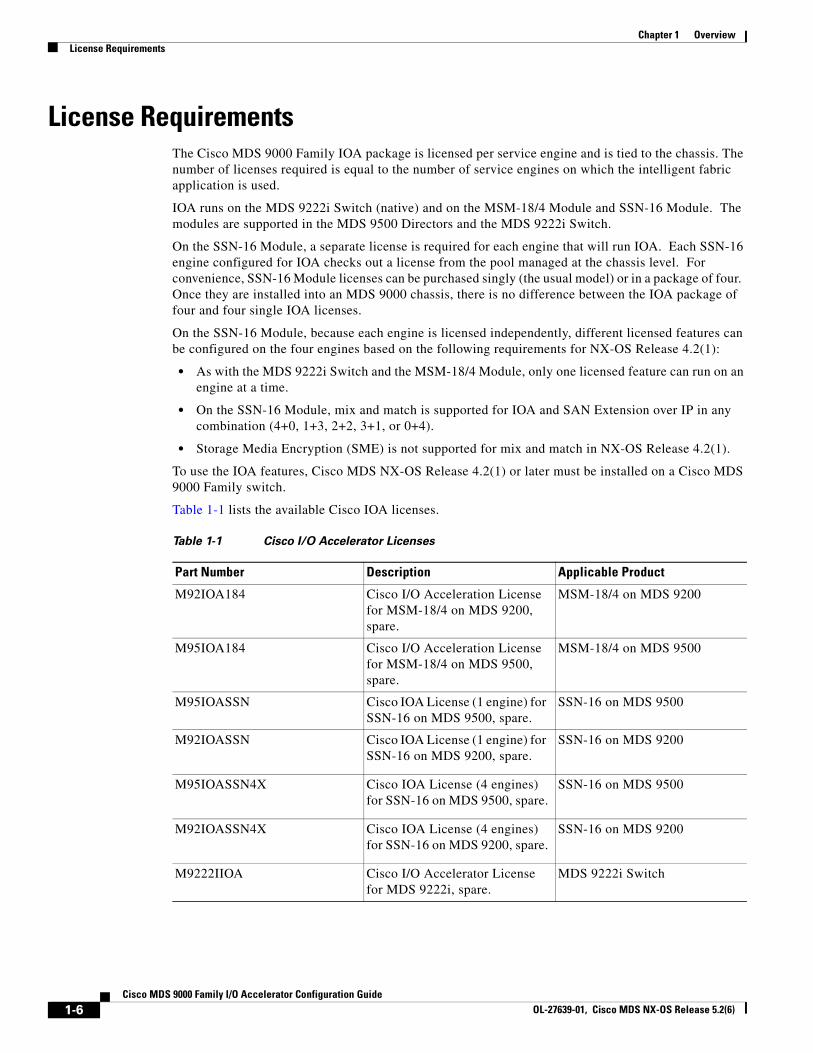
Table 1-1 lists the available Cisco IOA licenses.
Table 1-1 Cisco I/O Accelerator Licenses
Part Number Description Applicable Product
M92IOA184 Cisco I/O Acceleration License for MSM-18/4 on MDS 9200, spare.
MSM-18/4 on MDS 9200
M95IOA184 Cisco I/O Acceleration License for MSM-18/4 on MDS 9500, spare.
MSM-18/4 on MDS 9500
M95IOASSN Cisco IOA License (1 engine) for SSN-16 on MDS 9500, spare.
SSN-16 on MDS 9500
M92IOASSN Cisco IOA License (1 engine) for SSN-16 on MDS 9200, spare.
SSN-16 on MDS 9200
M95IOASSN4X Cisco IOA License (4 engines) for SSN-16 on MDS 9500, spare.
SSN-16 on MDS 9500
M92IOASSN4X Cisco IOA License (4 engines) for SSN-16 on MDS 9200, spare.
SSN-16 on MDS 9200
M9222IIOA Cisco I/O Accelerator License for MDS 9222i, spare.
MDS 9222i Switch
1-6Cisco MDS 9000 Family I/O Accelerator Configuration Guide
OL-27639-01, Cisco MDS NX-OS Release 5.2(6)

Chapter 1 OverviewLicense Requirements
Note A device is either a switch or a module. When you enter the serial number for the device, make sure that you enter the serial number for the correct device; either the switch or the module for which you want to get the license. You can use the show license host-id command to find out which serial number to lock the license against.
1-7Cisco MDS 9000 Family I/O Accelerator Configuration Guide
OL-27639-01, Cisco MDS NX-OS Release 5.2(6)

Chapter 1 Overview License Requirements
1-8Cisco MDS 9000 Family I/O Accelerator Configuration Guide
OL-27639-01, Cisco MDS NX-OS Release 5.2(6)
Cisco MOL-27639-01, Cisco MDS NX-OS Release 5.2(6)
C H A P T E R 2
Getting StartedThis chapter provides an overview of the basic configurations that need to be completed before getting started with IOA-specific configurations:
• Enabling SSH, page 2-1
• Enabling CFS, page 2-1
• IP Access Lists, page 2-2
• Zone Default Policy, page 2-2
• FC-Redirect, page 2-2
• Configuring FC-Redirect v2 Mode, page 2-3
• Using FC-Redirect with CFS Regions, page 2-4
• Using IOA Cluster with IPFC Interface, page 2-5
Enabling SSHSSH needs to be enabled on all the IOA switches for Cisco DCNM-SAN to provision IOA. By default, the SSH service is enabled with the RSA key.
To enable the SSH service, follow these steps:
Command Purpose
Step 1 switch# config t Enters configuration mode.
Step 2 switch(config)# feature sshupdated
Enables the use of the SSH service.
For more information about the SSH service, refer to the Cisco MDS 9000 Family NX-OS Security Configuration Guide.
Enabling CFSCFS must be enabled on the IOA switches as well as those switches of which the hosts and targets are directly connected to. FC-Redirect internally uses CFS to configure the rules for any given flow in the fabric.
2-1DS 9000 Family I/O Accelerator Configuration Guide
Chapter 2 Getting Started IP Access Lists
To globally enable CFS distribution on a switch, follow these steps:
Command Purpose
Step 1 switch# config tswitch(config)#
Enters configuration mode.
Step 2 switch(config)# cfs distribute Enables (default) CFS distribution on the switch.
For more information about CFS, refer to the Cisco MDS 9000 Family NX-OS System Management Configuration Guide.
IP Access ListsCluster communication requires the use of the Management interface. IP ACL configurations must allow UDP and TCP traffic on ports 9333, 9334, 9335, and 9336.
Zone Default PolicyFor FC-Redirect to work correctly, the default zone policy on all the switches in the IOA environment must be configured to deny and the initiator-target pairs must be configured in user-defined zones.
FC-RedirectThis section includes the following topics:
• FC-Redirect Unsupported Switches, page 2-2
• FC-Redirect Requirements, page 2-3
FC-Redirect Unsupported SwitchesIOA does not support any FCoE connected devices including devices connected through the MDS FCoE linecard (DX-X9708-K9).
In Cisco MDS NX-OS Release 5.2(x), you cannot install a FCoE module in a switch that is running DMM, SME, or IOA.
FC-Redirect is not supported on the following switches, which also means that IOA is not supported:
• Cisco MDS 9148 Switch
• Cisco MDS 9140 Switch
• Cisco MDS 9134 Switch
• Cisco MDS 9124 Switch
• Cisco MDS 9120 Switch
• Cisco MDS 9020 Switch
2-2Cisco MDS 9000 Family I/O Accelerator Configuration Guide
OL-27639-01, Cisco MDS NX-OS Release 5.2(6)
Chapter 2 Getting StartedConfiguring FC-Redirect v2 Mode
FC-Redirect RequirementsFC-Redirect requirements for IOA include the following:
• The MDS switch with the MSM-18/4 Module installed or the 9222i Switch needs to be running Cisco MDS NX-OS Release 4.2(1) or later.
• The targets must be connected to a FC-Redirect-capable switch running Cisco MDS NX-OS Release 4.2(1) or later. The hosts must be connected to a FC-Redirect-capable switch running Cisco MDS SAN-OS Release 3.3(1c) or later.
• 32 targets per MSM-18/4 Module can be FC-Redirected.
• In FC-Redirect v2 mode, up to 128 hosts per target are supported. If you do not enable FC-Redirect v2, this is limited to 16 hosts per target.
• CFS is enabled by default. Ensure that the CFS is enabled on the switches that have the host and the target connected. Also ensure that the CFS is not disabled on switches that are part of the IOA cluster.
• Advanced zoning capabilities like quality of service (QoS), logical unit number (LUN) zoning, and read-only LUNs must not be used for FC-Redirect hosts and targets.
Configuring FC-Redirect v2 ModeTo enable the v2 mode in FC-Redirect, use the fc-redirect version2 enable command in configuration mode. To disable the v2 mode in FC-Redirect, use the no form of the command.
This command is used to increase scalability of FC-Redirect. Disabling v2 mode after it is enabled in the fabric is not recommended. However, if you want to disable v2 mode, you cannot disable it until all FC-Redirect configurations are deleted. FC-Redirect configurations can be deleted only by deleting all corresponding application configurations.
The MDS switches not running Cisco NX-OS 3.3(1c) and later cannot be added to the fabric after the v2 mode is enabled. If the switches are added, all further FC-Redirect configuration changes will fail across the fabric. This could lead to traffic disruption for applications such as IOA, SME, and DMM.
Use the show fc-redirect configs command to see the list of applications that create FC-Redirect configurations.
If v2 mode is enabled in the fabric and you want to move a switch to a different fabric, use the clear fc-redirect decommission-switch command before moving the switch to a different fabric. If the mode is not enabled, all switches in the new fabric will be converted to v2 mode automatically.
Note Ensure that there are no fabric changes or upgrades in progress. For more information see “Software Requirements” section on page 1-5. Use the show fc-redirect peer-switches command (UP state) to see all the switches in the fabric.
To enable v2 mode in FC-Redirect, follow these steps:
Step 1 Enter the following command:
switch# config tswitch(config)# fc-redirect version2 enable
Step 2 Enter yes.
2-3Cisco MDS 9000 Family I/O Accelerator Configuration Guide
OL-27639-01, Cisco MDS NX-OS Release 5.2(6)
Chapter 2 Getting Started Using FC-Redirect with CFS Regions
Please make sure to read and understand the following implicationsbefore proceeding further:1) This is a Fabric wide configuration. All the switches in thefabric will be configured in Version2 mode.Any new switchesadded to the fabric will automatically be configured in version2mode.2) SanOS 3.2.x switches CANNOT be added to the Fabric after Version2mode is enabled. If any 3.2.x switch is added when Version2 modeis enabled, all further FC-Redirect Configuration changes will Failacross the fabric. This could lead to traffic disruption forapplications like SME.3) If enabled, Version2 mode CANNOT be disabled till all FC-Redirectconfigurations are deleted. FC-Redirect configurations can bedeleted ONLY after all the relevant application configurationsare deleted. Please use the command 'show fc-redirect configs'to see the list of applications that created FC-Redirectconfigurations.4) 'write erase' will NOT disable this command. After 'write erase'on ANY switch in the fabric, the user needs to do:'clear fc-redirect decommission-switch'on that that switch. Without that, if the user moves the switchto a different fabric it will try to convert all the switchesin the fabric to Version2 mode automatically. This might leadto Error conditions and hence Traffic disruption.Do you want to continue? (Yes/No) [No]Yes
Step 3 Enter yes.
Before proceeding further, please check the following:1) All the switches in the fabric are seen in the output of'show fc-redirect peer-switches' command and are in 'UP' state.2) All switches in the fabric are running SanOS version 3.3.x orhigher.3) Please make sure the Fabric is stable ie.,No fabric changes/upgrades in progressDo you want to continue? (Yes/No) [No] Yes
Using FC-Redirect with CFS Regions The FC-Redirect feature uses Cisco Fabric Services (CFS) regions to distribute the FC-Redirect configuration. By default, the configuration is propagated to all FC-Redirect-capable switches in the fabric. CFS regions can be used to restrict the distribution of the FC-Redirect configuration.
Note Using FC Redirect with CFS regions is an optional configuration only if the number of switches in the SAN exceeds the scalability limit supported by IOA. As of MDS NX-OS Release 4.2(1), the number of switches supported in a fabric is 34.
To learn more about CFS regions, refer to the Cisco MDS 9000 Family NX-OS System Management Configuration Guide.
Guidelines for Designing CFS Regions For FC-RedirectTo design CFS regions for FC-Redirect, follow these guidelines:
2-4Cisco MDS 9000 Family I/O Accelerator Configuration Guide
OL-27639-01, Cisco MDS NX-OS Release 5.2(6)
Chapter 2 Getting StartedUsing IOA Cluster with IPFC Interface
• Ensure that the CFS region configuration for FC-Redirect can be applied to all FC-Redirect-based applications. The applications include Cisco SME, Cisco DMM, Cisco IOA, and any future applications.
• Ensure that all FC-Redirect-capable switches, that are connected to the hosts, targets, and the application switches (switches with MSM-18/4 modules in a cluster), are configured in the same region.
• All switches in the region must have a common VSAN.
• For existing IOA installations, refer to “Configuring CFS Regions For FC-Redirect” section on page 2-5 for steps on migrating to CFS regions.
• Remove all instances of the previous configurations when a switch is moved to a region or moved out of a region.
Configuring CFS Regions For FC-RedirectTo configure the CFS regions for FC-Redirect, do the following tasks:
Step 1 Configure a switch in the CFS region as shown in the following example:
switch# config tswitch(config)# cfs region 2switch(config-cfs-region)# fc-redirectswitch(config)# end
Repeat this step for all the switches that are included in the specified region.
Step 2 Confirm that all the required switches are available in the CFS region by entering the show fc-redirect peer-switches command.
Step 3 To migrate existing Cisco IOA installations to CFS regions for FC-Redirect, delete all the existing FC-Redirect configurations created by the switches in other regions from each switch. To remove the configurations, perform the following steps:
a. Obtain a list of all FC-Redirect configurations by entering the show fc-redirect configs command.
b. Remove all configurations created by the switches in other regions by using the clear fc-redirect configs command. The configurations are removed from the switches but the switches remain active in the region in which they are created.
Using IOA Cluster with IPFC InterfaceInternet protocol over Fibre Channel (IPFC) provides IP forwarding or in-band switch management over a Fibre Channel interface (instead of management using the Gigabit Ethernet mgmt 0 interface). You can use IPFC to specify that IP frames be transported over Fibre Channel using encapsulation techniques. IP frames are encapsulated into Fibre Channel frames so that cluster management information can transmit across the Fibre Channel network without using an overlay Ethernet network.
When an IOA cluster communicates via the IPFC interface, the cluster management messages can be sent and received on Fibre Channel ISLs by encapsulating cluster management messages in Fibre Channel frames instead of using the management interface.
2-5Cisco MDS 9000 Family I/O Accelerator Configuration Guide
OL-27639-01, Cisco MDS NX-OS Release 5.2(6)
Chapter 2 Getting Started Using IOA Cluster with IPFC Interface
Note Configuring IOA cluster with the IPFC interface is optional and is supported in Cisco MDS NX-OS Release 5.0(4c) or later. Support for GUI for configuring IOA cluster with the IPFC interface might be added in the future releases.
Note You must configure the nodes in an IOA cluster either to use an IPFC interface or a management interface. We do not recommend using the combination of two interface configurations.
Task Flow for Configuring IOA Cluster To Use the IPFC InterfaceTo configure IOA cluster using the IPFC Interface, follow these steps:
Step 1 Create an IPFC interface.
a. Create a VSAN to use for in-band management.
b. Configure an IPv4 address and subnet mask for the VSAN interface.
c. Enable IPv4 routing.
d. Verify connectivity.
Step 2 Create an IOA cluster.
Step 3 Change the local node to use IPFC interface’s IPv4 address.
Step 4 Add the IOA interfaces to the cluster.
Step 5 Add the remote node with IPFC interface IPv4 address.
Step 6 Add the IOA interface of the remote cluster.
Configuring IOA Cluster To Use the IPFC InterfaceThe process of configuring an IOA cluster to use the IPFC interface involves a number of configuration tasks that should be completed in the following order:
• Creating a VSAN Interface and Configuring IPv4 Addresses, page 2-6
• Enabling IPv4 Routing, page 2-7
• Verifying Connectivity, page 2-7
• Creating IOA cluster and IOA interface in the Local Node, page 2-8
• Verifying Cluster Configuration, page 2-8
• Adding a Remote Node and IOA Interface to the Remote Node, page 2-8
• Verifying the Cluster Configuration, page 2-9
Creating a VSAN Interface and Configuring IPv4 Addresses
The first step in the process of configuring IOA cluster to use the IPFC interface is to create a VSAN interface and configure IPv4 addresses.
2-6Cisco MDS 9000 Family I/O Accelerator Configuration Guide
OL-27639-01, Cisco MDS NX-OS Release 5.2(6)
Chapter 2 Getting StartedUsing IOA Cluster with IPFC Interface
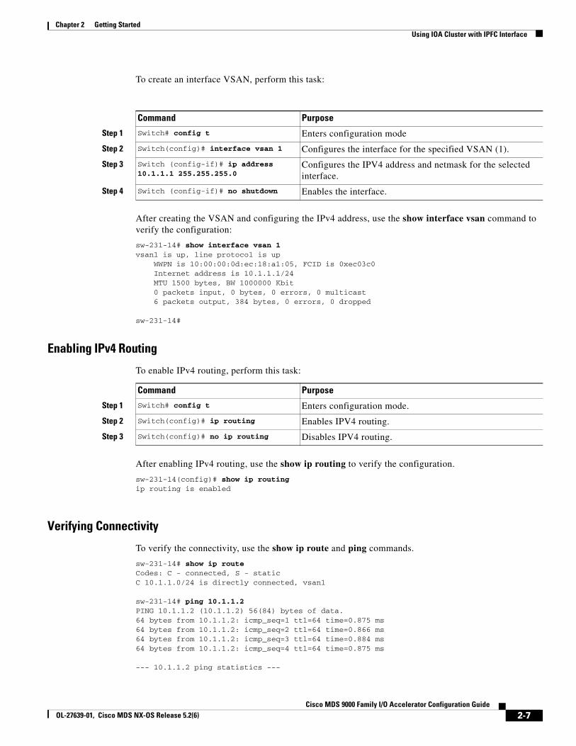
To create an interface VSAN, perform this task:
Command Purpose
Step 1 Switch# config t Enters configuration mode
Step 2 Switch(config)# interface vsan 1 Configures the interface for the specified VSAN (1).
Step 3 Switch (config-if)# ip address 10.1.1.1 255.255.255.0
Configures the IPV4 address and netmask for the selected interface.
Step 4 Switch (config-if)# no shutdown Enables the interface.
After creating the VSAN and configuring the IPv4 address, use the show interface vsan command to verify the configuration:
sw-231-14# show interface vsan 1vsan1 is up, line protocol is up WWPN is 10:00:00:0d:ec:18:a1:05, FCID is 0xec03c0 Internet address is 10.1.1.1/24 MTU 1500 bytes, BW 1000000 Kbit 0 packets input, 0 bytes, 0 errors, 0 multicast 6 packets output, 384 bytes, 0 errors, 0 dropped
sw-231-14#
Enabling IPv4 Routing
To enable IPv4 routing, perform this task:
Command Purpose
Step 1 Switch# config t Enters configuration mode.
Step 2 Switch(config)# ip routing Enables IPV4 routing.
Step 3 Switch(config)# no ip routing Disables IPV4 routing.
After enabling IPv4 routing, use the show ip routing to verify the configuration.
sw-231-14(config)# show ip routingip routing is enabled
Verifying Connectivity
To verify the connectivity, use the show ip route and ping commands.
sw-231-14# show ip routeCodes: C - connected, S - staticC 10.1.1.0/24 is directly connected, vsan1
sw-231-14# ping 10.1.1.2PING 10.1.1.2 (10.1.1.2) 56(84) bytes of data.64 bytes from 10.1.1.2: icmp_seq=1 ttl=64 time=0.875 ms64 bytes from 10.1.1.2: icmp_seq=2 ttl=64 time=0.866 ms64 bytes from 10.1.1.2: icmp_seq=3 ttl=64 time=0.884 ms64 bytes from 10.1.1.2: icmp_seq=4 ttl=64 time=0.875 ms
--- 10.1.1.2 ping statistics ---
2-7Cisco MDS 9000 Family I/O Accelerator Configuration Guide
OL-27639-01, Cisco MDS NX-OS Release 5.2(6)
Chapter 2 Getting Started Using IOA Cluster with IPFC Interface
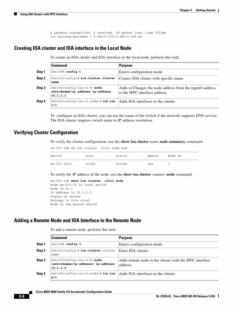
4 packets transmitted, 4 received, 0% packet loss, time 3023msrtt min/avg/max/mdev = 0.866/0.875/0.884/0.006 ms
Creating IOA cluster and IOA interface in the Local Node
To create an IOA cluster and IOA interface in the local node, perform this task:
Command Purpose
Step 1 Switch# config t Enters configuration mode
Step 2 Switch(config)# ioa cluster cluster name
Creates IOA cluster with specific name.
Step 3 Switch(config-ioa-cl)# node switchname/ip address ip-address 10.1.1.1
Adds or Changes the node address from the mgmt0 address to the IPFC interface address.
Step 4 Switch(config-ioa-cl-node)# int ioa 1/1
Adds IOA interfaces to the cluster.
To configure an IOA cluster, you can use the name of the switch if the network supports DNS service. The IOA cluster requires switch name to IP address resolution.
Verifying Cluster Configuration
To verify the cluster configuration, use the show ioa cluster name node summary command.
sw-231-14# sh ioa cluster cltr1 node sum-------------------------------------------------------------------------------Switch Site Status Master Node ID-------------------------------------------------------------------------------sw-231-14(L) site2 online yes 1
To verify the IP address of the node, use the show ioa cluster <name> node command.
sw-231-14# show ioa cluster cltr1 nodeNode sw-231-14 is local switchNode ID is 1IP address is 10.1.1.1Status is onlineBelongs to Site site2Node is the master switch
Adding a Remote Node and IOA Interface to the Remote Node
To add a remote node, perform this task:
Command Purpose
Step 1 Switch# config t Enters configuration mode.
Step 2 Swtich(config)# ioa cluster cluster name
Enter IOA cluster.
Step 3 Switch(config-ioa-cl)# node <switchname/ip address> ip-address 10.1.1.2
Adds remote node to the cluster with the IPFC interface address.
Step 4 Switch(config-ioa-cl-node)# int ioa 4/1
Adds IOA interfaces to the cluster.
2-8Cisco MDS 9000 Family I/O Accelerator Configuration Guide
OL-27639-01, Cisco MDS NX-OS Release 5.2(6)
Chapter 2 Getting StartedUsing IOA Cluster with IPFC Interface
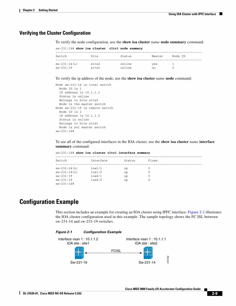
Verifying the Cluster Configuration
To verify the node configuration, use the show ioa cluster name node summary command:
sw-231-14# show ioa cluster cltr1 node summary-------------------------------------------------------------------------------Switch Site Status Master Node ID-------------------------------------------------------------------------------sw-231-14(L) site2 online yes 1sw-231-19 site1 online no 2
To verify the ip address of the node, use the show ioa cluster name node command:
Node sw-231-14 is local switch Node ID is 1 IP address is 10.1.1.1 Status is online Belongs to Site site2 Node is the master switchNode sw-231-19 is remote switch Node ID is 2 IP address is 10.1.1.2 Status is online Belongs to Site site1 Node is not master switchsw-231-14#
To see all of the configured interfaces in the IOA cluster, use the show ioa cluster name interface summary command:
sw-231-14# show ioa cluster cltr1 interface summary-------------------------------------------------------------------------------Switch Interface Status Flows-------------------------------------------------------------------------------sw-231-14(L) ioa1/1 up 0sw-231-14(L) ioa1/2 up 0sw-231-19 ioa4/1 up 0sw-231-19 ioa4/2 up 0sw-231-14#
Configuration ExampleThis section includes an example for creating an IOA cluster using IPFC interface. Figure 2-1 illustrates the IOA cluster configuration used in this example. The sample topology shows the FC ISL between sw-231-14 and sw-231-19 switches.
Figure 2-1
Interface vsan 1 : 10.1.1.2IOA stie : site1
Interface vsan 1 : 10.1.1.1IOA stie : site2
FCISL
Sw-231-19 Sw-231-14 3101
52
Configuration Example
2-9Cisco MDS 9000 Family I/O Accelerator Configuration Guide
OL-27639-01, Cisco MDS NX-OS Release 5.2(6)
Chapter 2 Getting Started Using IOA Cluster with IPFC Interface
• Creating an Interface VSAN, page 2-10
• Verifying the Configuration, page 2-10
• Verifying the Connectivity, page 2-11
• Configuring IOA Site on Switch sw-231-14, page 2-11
• Configuring IOA Site on Switch sw-231-19, page 2-11
• Changing the Node to Use IPFC Interface Address, page 2-11
• Adding a Remote Node to the IOA Cluster, page 2-11
• Adding an IOA Interface to the Switch sw-231-14, page 2-12
• Adding an IOA Interface to the Switch sw-231-19, page 2-12
• Verifying the Cluster Configuration, page 2-12
• Verifying the IP Address, page 2-12
• Verifying the IOA Interface, page 2-13
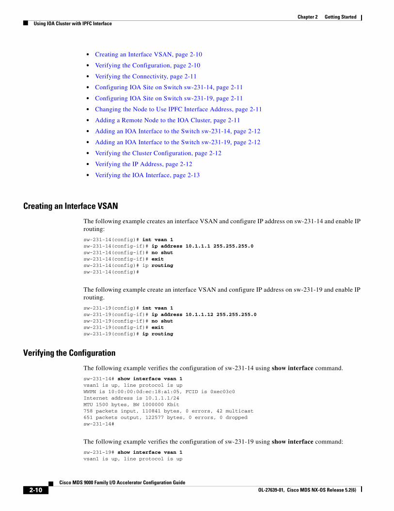
Creating an Interface VSAN
The following example creates an interface VSAN and configure IP address on sw-231-14 and enable IP routing:
sw-231-14(config)# int vsan 1sw-231-14(config-if)# ip address 10.1.1.1 255.255.255.0sw-231-14(config-if)# no shutsw-231-14(config-if)# exitsw-231-14(config)# ip routingsw-231-14(config)#
The following example create an interface VSAN and configure IP address on sw-231-19 and enable IP routing.
sw-231-19(config)# int vsan 1sw-231-19(config-if)# ip address 10.1.1.12 255.255.255.0sw-231-19(config-if)# no shutsw-231-19(config-if)# exitsw-231-19(config)# ip routing
Verifying the Configuration
The following example verifies the configuration of sw-231-14 using show interface command.
sw-231-14# show interface vsan 1vsan1 is up, line protocol is upWWPN is 10:00:00:0d:ec:18:a1:05, FCID is 0xec03c0Internet address is 10.1.1.1/24MTU 1500 bytes, BW 1000000 Kbit758 packets input, 110841 bytes, 0 errors, 42 multicast651 packets output, 122577 bytes, 0 errors, 0 droppedsw-231-14#
The following example verifies the configuration of sw-231-19 using show interface command:
sw-231-19# show interface vsan 1vsan1 is up, line protocol is up
2-10Cisco MDS 9000 Family I/O Accelerator Configuration Guide
OL-27639-01, Cisco MDS NX-OS Release 5.2(6)
Chapter 2 Getting StartedUsing IOA Cluster with IPFC Interface
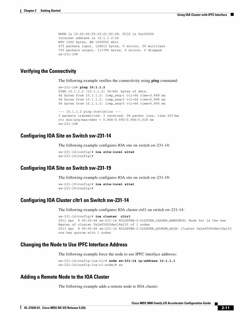
WWPN is 10:00:00:05:30:01:9f:09, FCID is 0xc60000Internet address is 10.1.1.2/24MTU 1500 bytes, BW 1000000 Kbit675 packets input, 124613 bytes, 0 errors, 36 multicast755 packets output, 111785 bytes, 0 errors, 0 droppedsw-231-19#
Verifying the Connectivity
The following example verifies the connectivity using ping command:
sw-231-14# ping 10.1.1.2PING 10.1.1.2 (10.1.1.2) 56(84) bytes of data.64 bytes from 10.1.1.2: icmp_seq=1 ttl=64 time=0.868 ms64 bytes from 10.1.1.2: icmp_seq=2 ttl=64 time=0.898 ms64 bytes from 10.1.1.2: icmp_seq=3 ttl=64 time=0.906 ms
--- 10.1.1.2 ping statistics ---3 packets transmitted, 3 received, 0% packet loss, time 2017msrtt min/avg/max/mdev = 0.868/0.890/0.906/0.038 mssw-231-14#
Configuring IOA Site on Switch sw-231-14
The following example configures IOA site on switch sw-231-14:
sw-231-14(config)# ioa site-local site2sw-231-14(config)#
Configuring IOA Site on Switch sw-231-19
The following example configures IOA site on switch sw-231-19:
sw-231-19(config)# ioa site-local site1sw-231-19(config)#
Configuring IOA Cluster cltr1 on Switch sw-231-14
The following example configures IOA cluster ctrl1 on switch sw-231-14:
sw-231-14(config)# ioa cluster cltr12011 Apr 8 05:00:46 sw-231-14 %CLUSTER-2-CLUSTER_LEADER_ANNOUNCE: Node 0x1 is the new Master of cluster 0x2e05000dec18a133 of 1 nodes2011 Apr 8 05:00:46 sw-231-14 %CLUSTER-2-CLUSTER_QUORUM_GAIN: Cluster 0x2e05000dec18a133 now has quorum with 1 nodes
Changing the Node to Use IPFC Interface Address
The following example force the node to use IPFC interface addresss:
sw-231-14(config-ioa-cl)# node sw-231-14 ip-address 10.1.1.1sw-231-14(config-ioa-cl-node)# ex
Adding a Remote Node to the IOA Cluster
The following example adds a remote node to IOA cluster:
2-11Cisco MDS 9000 Family I/O Accelerator Configuration Guide
OL-27639-01, Cisco MDS NX-OS Release 5.2(6)
Chapter 2 Getting Started Using IOA Cluster with IPFC Interface
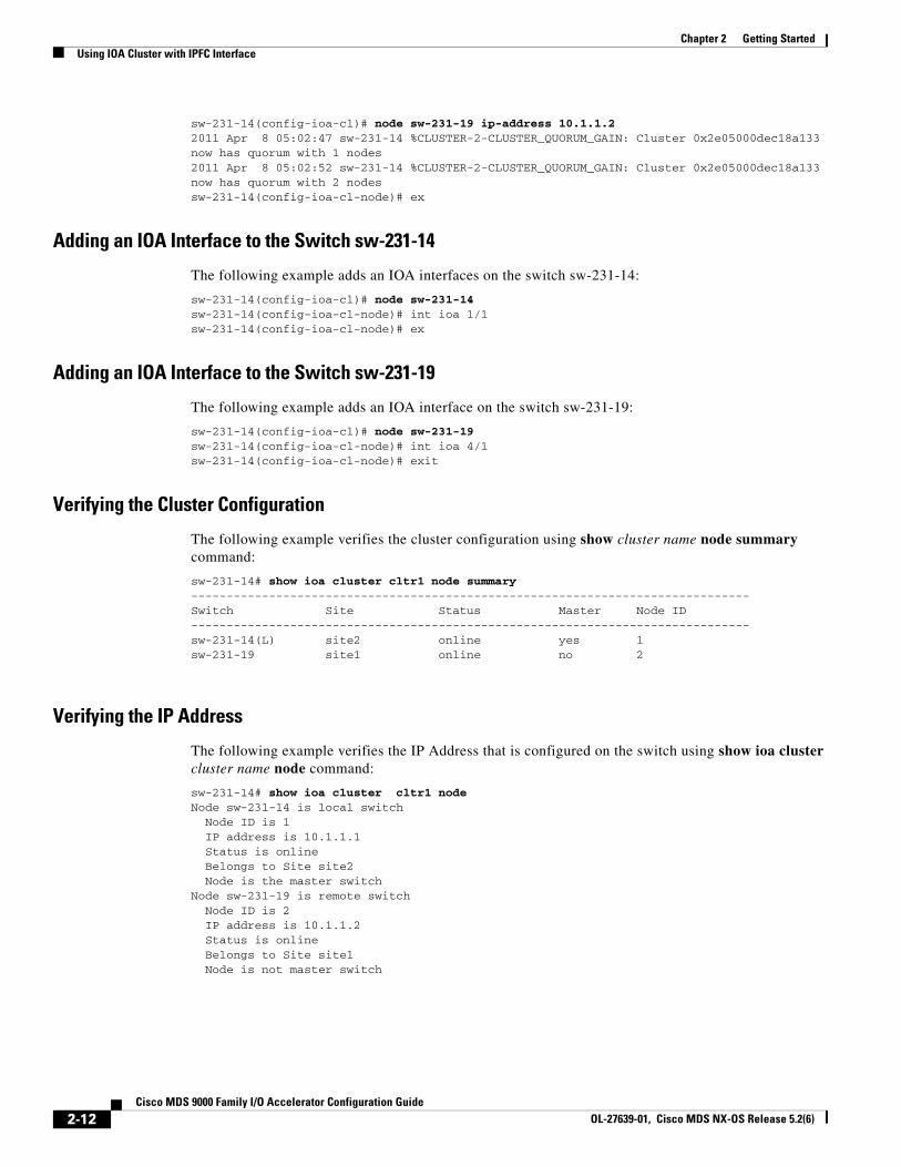
sw-231-14(config-ioa-cl)# node sw-231-19 ip-address 10.1.1.22011 Apr 8 05:02:47 sw-231-14 %CLUSTER-2-CLUSTER_QUORUM_GAIN: Cluster 0x2e05000dec18a133 now has quorum with 1 nodes2011 Apr 8 05:02:52 sw-231-14 %CLUSTER-2-CLUSTER_QUORUM_GAIN: Cluster 0x2e05000dec18a133 now has quorum with 2 nodessw-231-14(config-ioa-cl-node)# ex
Adding an IOA Interface to the Switch sw-231-14
The following example adds an IOA interfaces on the switch sw-231-14:
sw-231-14(config-ioa-cl)# node sw-231-14sw-231-14(config-ioa-cl-node)# int ioa 1/1sw-231-14(config-ioa-cl-node)# ex
Adding an IOA Interface to the Switch sw-231-19
The following example adds an IOA interface on the switch sw-231-19:
sw-231-14(config-ioa-cl)# node sw-231-19sw-231-14(config-ioa-cl-node)# int ioa 4/1sw-231-14(config-ioa-cl-node)# exit
Verifying the Cluster Configuration
The following example verifies the cluster configuration using show cluster name node summary command:
sw-231-14# show ioa cluster cltr1 node summary-------------------------------------------------------------------------------Switch Site Status Master Node ID-------------------------------------------------------------------------------sw-231-14(L) site2 online yes 1sw-231-19 site1 online no 2
Verifying the IP Address
The following example verifies the IP Address that is configured on the switch using show ioa cluster cluster name node command:
sw-231-14# show ioa cluster cltr1 nodeNode sw-231-14 is local switch Node ID is 1 IP address is 10.1.1.1 Status is online Belongs to Site site2 Node is the master switchNode sw-231-19 is remote switch Node ID is 2 IP address is 10.1.1.2 Status is online Belongs to Site site1 Node is not master switch
2-12Cisco MDS 9000 Family I/O Accelerator Configuration Guide
OL-27639-01, Cisco MDS NX-OS Release 5.2(6)
Chapter 2 Getting StartedUsing IOA Cluster with IPFC Interface
Verifying the IOA Interface
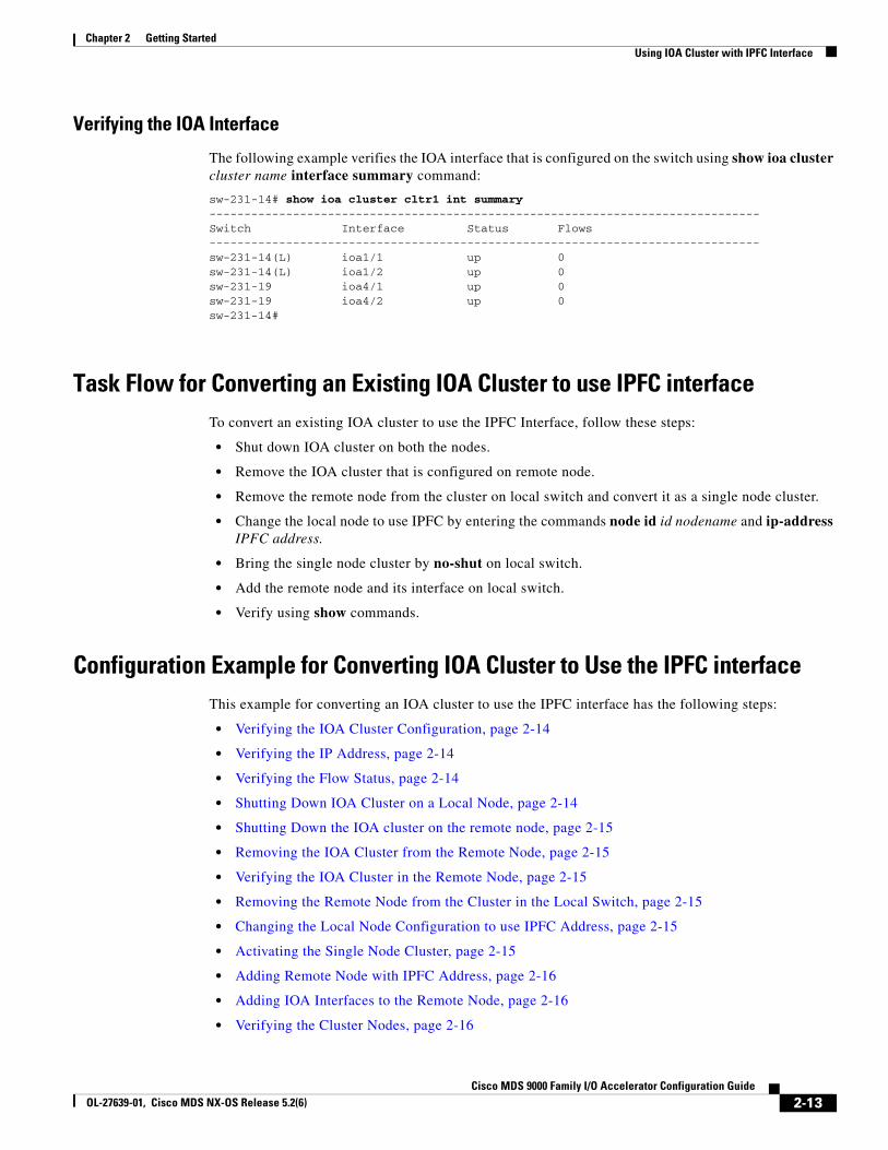
The following example verifies the IOA interface that is configured on the switch using show ioa cluster cluster name interface summary command:
sw-231-14# show ioa cluster cltr1 int summary-------------------------------------------------------------------------------Switch Interface Status Flows-------------------------------------------------------------------------------sw-231-14(L) ioa1/1 up 0sw-231-14(L) ioa1/2 up 0sw-231-19 ioa4/1 up 0sw-231-19 ioa4/2 up 0sw-231-14#
Task Flow for Converting an Existing IOA Cluster to use IPFC interfaceTo convert an existing IOA cluster to use the IPFC Interface, follow these steps:
• Shut down IOA cluster on both the nodes.
• Remove the IOA cluster that is configured on remote node.
• Remove the remote node from the cluster on local switch and convert it as a single node cluster.
• Change the local node to use IPFC by entering the commands node id id nodename and ip-address IPFC address.
• Bring the single node cluster by no-shut on local switch.
• Add the remote node and its interface on local switch.
• Verify using show commands.
Configuration Example for Converting IOA Cluster to Use the IPFC interfaceThis example for converting an IOA cluster to use the IPFC interface has the following steps:
• Verifying the IOA Cluster Configuration, page 2-14
• Verifying the IP Address, page 2-14
• Verifying the Flow Status, page 2-14
• Shutting Down IOA Cluster on a Local Node, page 2-14
• Shutting Down the IOA cluster on the remote node, page 2-15
• Removing the IOA Cluster from the Remote Node, page 2-15
• Verifying the IOA Cluster in the Remote Node, page 2-15
• Removing the Remote Node from the Cluster in the Local Switch, page 2-15
• Changing the Local Node Configuration to use IPFC Address, page 2-15
• Activating the Single Node Cluster, page 2-15
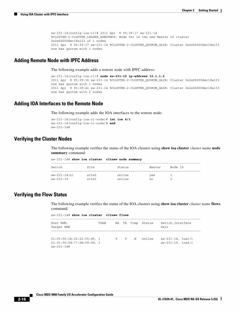
• Adding Remote Node with IPFC Address, page 2-16
• Adding IOA Interfaces to the Remote Node, page 2-16
• Verifying the Cluster Nodes, page 2-16
2-13Cisco MDS 9000 Family I/O Accelerator Configuration Guide
OL-27639-01, Cisco MDS NX-OS Release 5.2(6)
Chapter 2 Getting Started Using IOA Cluster with IPFC Interface
• Verifying the Flow Status, page 2-16
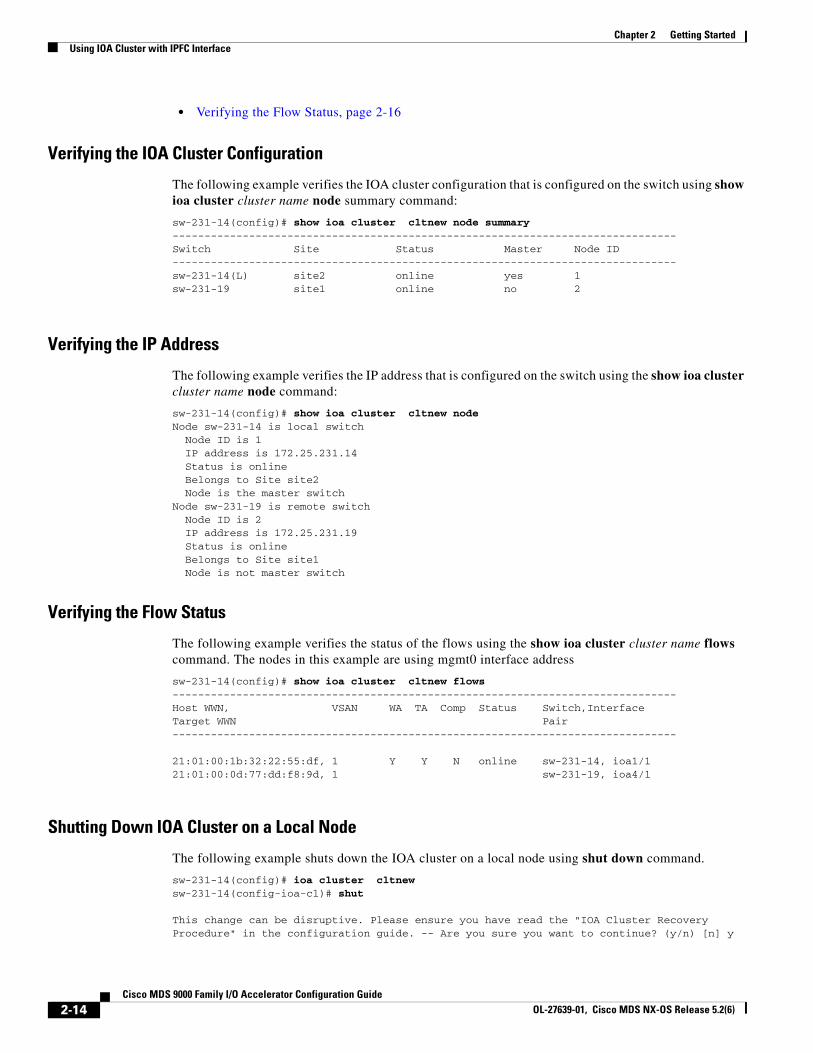
Verifying the IOA Cluster Configuration
The following example verifies the IOA cluster configuration that is configured on the switch using show ioa cluster cluster name node summary command:
sw-231-14(config)# show ioa cluster cltnew node summary-------------------------------------------------------------------------------Switch Site Status Master Node ID-------------------------------------------------------------------------------sw-231-14(L) site2 online yes 1sw-231-19 site1 online no 2
Verifying the IP Address
The following example verifies the IP address that is configured on the switch using the show ioa cluster cluster name node command:
sw-231-14(config)# show ioa cluster cltnew nodeNode sw-231-14 is local switch Node ID is 1 IP address is 172.25.231.14 Status is online Belongs to Site site2 Node is the master switchNode sw-231-19 is remote switch Node ID is 2 IP address is 172.25.231.19 Status is online Belongs to Site site1 Node is not master switch
Verifying the Flow Status
The following example verifies the status of the flows using the show ioa cluster cluster name flows command. The nodes in this example are using mgmt0 interface address
sw-231-14(config)# show ioa cluster cltnew flows-------------------------------------------------------------------------------Host WWN, VSAN WA TA Comp Status Switch,InterfaceTarget WWN Pair-------------------------------------------------------------------------------
21:01:00:1b:32:22:55:df, 1 Y Y N online sw-231-14, ioa1/121:01:00:0d:77:dd:f8:9d, 1 sw-231-19, ioa4/1
Shutting Down IOA Cluster on a Local Node
The following example shuts down the IOA cluster on a local node using shut down command.
sw-231-14(config)# ioa cluster cltnewsw-231-14(config-ioa-cl)# shut
This change can be disruptive. Please ensure you have read the "IOA Cluster Recovery Procedure" in the configuration guide. -- Are you sure you want to continue? (y/n) [n] y
2-14Cisco MDS 9000 Family I/O Accelerator Configuration Guide
OL-27639-01, Cisco MDS NX-OS Release 5.2(6)

Chapter 2 Getting StartedUsing IOA Cluster with IPFC Interface
2011 Apr 8 05:36:41 sw-231-14 %CLUSTER-2-CLUSTER_LOCAL_NODE_EXIT: Local Node 0x1 has left the Cluster 0x2e06000dec18a133
Shutting Down the IOA cluster on the remote node
The following example shuts down the IOA cluster on the remote node using shut down command:
sw-231-19(config)# ioa cluster cltnewsw-231-19(config-ioa-cl)# shutThis change can be disruptive. Please ensure you have read the "IOA Cluster Recovery Procedure" in the configuration guide. -- Are you sure you want to continue? (y/n) [n] y2011 Apr 8 05:37:03 sw-231-19 %CLUSTER-2-CLUSTER_LOCAL_NODE_EXIT: Local Node 0x2 has left the Cluster 0x2e06000dec18a133sw-231-19(config-ioa-cl)# exit
Removing the IOA Cluster from the Remote Node
The following example remove the IOA cluster from the remote node using the no ioa cluster cluster name command:
sw-231-19(config)# no ioa cluster cltnew
Verifying the IOA Cluster in the Remote Node
The following example verify the absence of IOA cluster on the remote node using show ioa cluster cluster name command:
sw-231-19(config)# show ioa clustersw-231-19(config)#
Removing the Remote Node from the Cluster in the Local Switch
The following example removes the remote node from the cluster in the local switch:
sw-231-14(config-ioa-cl)# no node sw-231-19sw-231-14(config-ioa-cl)# show ioa cluster cltnew node summary-------------------------------------------------------------------------------Switch Site Status Master Node ID-------------------------------------------------------------------------------sw-231-14(L) -- unknown (cluster is offline) 1
Changing the Local Node Configuration to use IPFC Address
The following example change the local node to use IPFC address:
sw-231-14(config-ioa-cl)# node id 1 sw-231-14 ip-address 10.1.1.1sw-231-14(config-ioa-cl-node)# exit
Activating the Single Node Cluster
The following example activates the single node cluster:
sw-231-14(config-ioa-cl)# no shutThis change can be disruptive. Please ensure you have read the "IOA Cluster Recovery Procedure" in the configuration guide. -- Are you sure you want to continue? (y/n) [n] y
2-15Cisco MDS 9000 Family I/O Accelerator Configuration Guide
OL-27639-01, Cisco MDS NX-OS Release 5.2(6)
Chapter 2 Getting Started Using IOA Cluster with IPFC Interface
sw-231-14(config-ioa-cl)# 2011 Apr 8 05:39:17 sw-231-14 %CLUSTER-2-CLUSTER_LEADER_ANNOUNCE: Node 0x1 is the new Master of cluster 0x2e06000dec18a133 of 1 nodes2011 Apr 8 05:39:17 sw-231-14 %CLUSTER-2-CLUSTER_QUORUM_GAIN: Cluster 0x2e06000dec18a133 now has quorum with 1 nodes
Adding Remote Node with IPFC Address
The following example adds a remote node with IPFC address:
sw-231-14(config-ioa-cl)# node sw-231-19 ip-address 10.1.1.22011 Apr 8 05:39:36 sw-231-14 %CLUSTER-2-CLUSTER_QUORUM_GAIN: Cluster 0x2e06000dec18a133 now has quorum with 1 nodes2011 Apr 8 05:39:41 sw-231-14 %CLUSTER-2-CLUSTER_QUORUM_GAIN: Cluster 0x2e06000dec18a133 now has quorum with 2 nodes
Adding IOA Interfaces to the Remote Node
The following example adds the IOA interfaces to the remote node:
sw-231-14(config-ioa-cl-node)# int ioa 4/1sw-231-14(config-ioa-cl-node)# endsw-231-14#
Verifying the Cluster Nodes
The following example verifies the status of the IOA clusters using show ioa cluster cluster name node summary command:
sw-231-14# show ioa cluster cltnew node summary-------------------------------------------------------------------------------Switch Site Status Master Node ID-------------------------------------------------------------------------------sw-231-14(L) site2 online yes 1sw-231-19 site1 online no 2
Verifying the Flow Status
The following example verifies the status of the IOA clusters using show ioa cluster cluster name flows command:
sw-231-14# show ioa cluster cltnew flows-------------------------------------------------------------------------------Host WWN, VSAN WA TA Comp Status Switch,InterfaceTarget WWN Pair-------------------------------------------------------------------------------
21:01:00:1b:32:22:55:df, 1 Y Y N online sw-231-14, ioa1/121:01:00:0d:77:dd:f8:9d, 1 sw-231-19, ioa4/1sw-231-14#
2-16Cisco MDS 9000 Family I/O Accelerator Configuration Guide
OL-27639-01, Cisco MDS NX-OS Release 5.2(6)
Cisco MOL-27639-01, Cisco MDS NX-OS Release 5.2(6)
C H A P T E R 3
Deployment ConsiderationsThis chapter describes the requirements and guidelines that are necessary to successfully deploy your Cisco I/O Accelerator SAN. Read this chapter before installing or configuring Cisco I/O Accelerator (IOA).
This chapter includes the following sections:
• Supported Topologies, page 3-1
• Deployment Guidelines, page 3-6
• Limitations and Restrictions, page 3-7
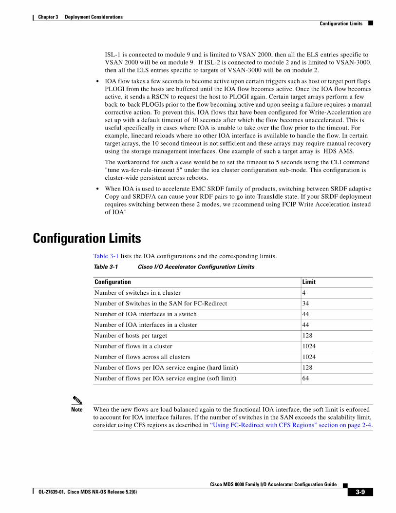
• Configuration Limits, page 3-9
Supported TopologiesThis section includes the following topics:
• Core-Edge Topology, page 3-1
• Edge-Core-Edge Topology, page 3-2
• Collapsed Core Topology, page 3-3
• Extended Core-Edge Topology, page 3-4
• Extending Across Multiple Sites, page 3-4
• IVR Topologies, page 3-5
• Other Topologies, page 3-6
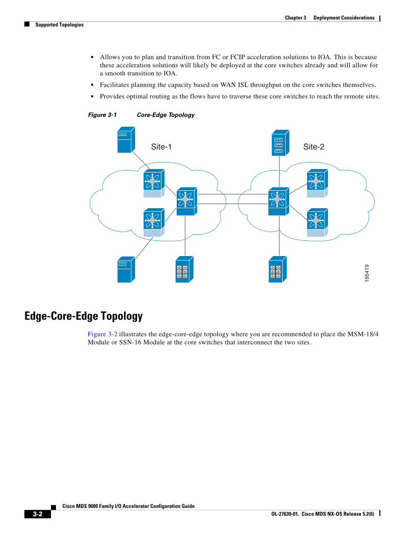
Core-Edge TopologyFigure 3-1 illustrates the core-edge topology where you are recommended to place the IOA interfaces (MSM-18/4 or SSN-16) in the core switches that interconnect the two sites. The ISLs interconnecting the two sites over a MAN or WAN are typically on the core switches as well, so this becomes a natural place to deploy the IOA service. This deployment provides the following benefits:
• Provides consolidation of IOA service at the core.
• Allows easy scalability of the IOA service engines based on the desired throughput.
3-1DS 9000 Family I/O Accelerator Configuration Guide
Chapter 3 Deployment Considerations Supported Topologies
• Allows you to plan and transition from FC or FCIP acceleration solutions to IOA. This is because these acceleration solutions will likely be deployed at the core switches already and will allow for a smooth transition to IOA.
• Facilitates planning the capacity based on WAN ISL throughput on the core switches themselves.
• Provides optimal routing as the flows have to traverse these core switches to reach the remote sites.
Figure 3-1 Core-Edge Topology
1954
19
Site-1 Site-2
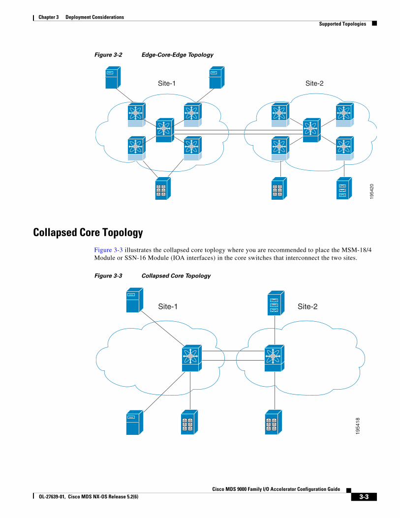
Edge-Core-Edge TopologyFigure 3-2 illustrates the edge-core-edge topology where you are recommended to place the MSM-18/4 Module or SSN-16 Module at the core switches that interconnect the two sites.
3-2Cisco MDS 9000 Family I/O Accelerator Configuration Guide
OL-27639-01, Cisco MDS NX-OS Release 5.2(6)
Chapter 3 Deployment ConsiderationsSupported Topologies
Figure 3-2 Edge-Core-Edge Topology
1954
20
Site-1 Site-2
Collapsed Core TopologyFigure 3-3 illustrates the collapsed core toplogy where you are recommended to place the MSM-18/4 Module or SSN-16 Module (IOA interfaces) in the core switches that interconnect the two sites.
Figure 3-3 Collapsed Core Topology
1954
18
Site-1 Site-2
3-3Cisco MDS 9000 Family I/O Accelerator Configuration Guide
OL-27639-01, Cisco MDS NX-OS Release 5.2(6)
Chapter 3 Deployment Considerations Supported Topologies
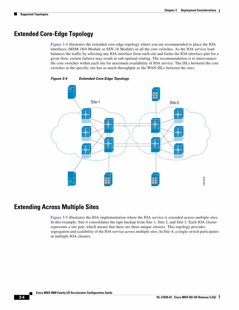
Extended Core-Edge TopologyFigure 3-4 illustrates the extended core-edge topology where you are recommended to place the IOA interfaces (MSM-18/4 Module or SSN-16 Module) in all the core switches. As the IOA service load balances the traffic by selecting any IOA interface from each site and forms the IOA interface pair for a given flow, certain failures may result in sub-optimal routing. The recommendation is to interconnect the core switches within each site for maximum availability of IOA service. The ISLs between the core switches in the specific site has as much throughput as the WAN ISLs between the sites.
Figure 3-4 Extended Core-Edge Topology
19
54
22
Site-1 Site-2
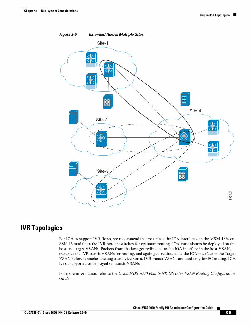
Extending Across Multiple SitesFigure 3-5 illustrates the IOA implementation where the IOA service is extended across multiple sites. In this example, Site-4 consolidates the tape backup from Site-1, Site-2, and Site-3. Each IOA cluster represents a site pair, which means that there are three unique clusters. This topology provides segregation and scalability of the IOA service across multiple sites. In Site-4, a single switch participates in multiple IOA clusters.
3-4Cisco MDS 9000 Family I/O Accelerator Configuration Guide
OL-27639-01, Cisco MDS NX-OS Release 5.2(6)
Chapter 3 Deployment ConsiderationsSupported Topologies
Figure 3-5 Extended Across Multiple Sites
1954
21
Site-1
Site-4
Site-2
Site-3
IVR TopologiesFor IOA to support IVR flows, we recommend that you place the IOA interfaces on the MSM-18/4 or SSN-16 module in the IVR border switches for optimum routing. IOA must always be deployed on the host and target VSANs. Packets from the host get redirected to the IOA interface in the host VSAN, traverses the IVR transit VSANs for routing, and again gets redirected to the IOA interface in the Target VSAN before it reaches the target and vice-versa. IVR transit VSANs are used only for FC routing. IOA is not supported or deployed on transit VSANs.
For more information, refer to the Cisco MDS 9000 Family NX-OS Inter-VSAN Routing Configuration Guide.
3-5Cisco MDS 9000 Family I/O Accelerator Configuration Guide
OL-27639-01, Cisco MDS NX-OS Release 5.2(6)
Chapter 3 Deployment Considerations Deployment Guidelines
Other TopologiesIn certain other topologies, the edge switches are connected across the WAN. In such cases, we recommend that you do the following:
• Transition the WAN links from the edge to core switches to provide consolidation and optimal routing services.
• Deploy the IOA service in the core switches.
Note IOA is supported for IVR flows starting from the Cisco MDS NX-OS Release 5.0(1a).
Deployment Guidelines This section includes the following topics:
• General Guidelines, page 3-6
• Scalability and Optimal Performance Considerations, page 3-6
• Resiliency Considerations, page 3-7
General GuidelinesWhen you deploy IOA, consider these general configuration guidelines:
• The IOA flows bound to the IOA interfaces on the module undergoing an upgrade will be affected.
• Clustering infrastructure uses the management IP network connectivity to communicate with the other switches. In the case of a switchover, the management IP network connectivity should be restored quickly to preserve the cluster communication. If the management port is connected to a Layer 2 switch, spanning-tree must be disabled on these ports. In a Cisco Catalyst 6000 Series switch, you can implement this by configuring the spanning-tree portfast command on these ports which will treat these ports as access or host ports.
Scalability and Optimal Performance ConsiderationsFor maximum scalability and optimal performance, follow these IOA configuration guidelines:
• Zoning considerations: In certain tape backup environments, a common practice is to zone every backup server with every tape drive available to allow sharing of tape drives across all the backup servers. For small and medium tape backup environments, this may be retained when deploying IOA. For large backup environments, the scalability limit of number of flows in IOA must be considered to check if the zoning configuration can be retained. Best practice for such an environment is to create multiple tape drive pools, each with a set of tape drives and zones of only a set of backup servers to a particular tape drive pool. This allows sharing of tape drives and drastically reduces the scalability requirements on IOA.
• Deploy IOA interfaces (MSM-18/4 or SSN-16) in the core switches in both core-edge and edge-core-edge topologies. When multiple core switches are interconnected across the MAN or WAN, do the following:
– Deploy the IOA interfaces equally among the core switches for high availability.
3-6Cisco MDS 9000 Family I/O Accelerator Configuration Guide
OL-27639-01, Cisco MDS NX-OS Release 5.2(6)
Chapter 3 Deployment ConsiderationsLimitations and Restrictions
– Interconnect core switches in each site for optimal routing.
• Plan for Geneneration 2 and above line cards to avoid any FC-Redirect limitations. There is a limit of only 32 targets per switch if Generation 1 modules are used to link the ISLs connecting the IOA switch and target switches or if the host is directly connected to a Generation 1 module.
• Depending on the WAN transport used, you may have to tune the Fibre Channel extended B2B credits for the round-trip delay between the sites.
Resiliency ConsiderationsWhen you configure IOA, consider the following resiliency guidelines:
• Plan to have a minimum of one additional IOA service engine for each site for handling IOA service engine failures.
• Tuning for E_D_TOV: Fibre Channel Error Detect Timeout Value (E_D_TOV) is used by Fibre Channel drives to detect errors if any data packet in a sequence takes longer than the specified timeout value. The default timeout value for E_D_TOV is 2 seconds. IOA has an built-in reliability protocol (LRTP) to detect and recover from ISL failures by doing the necessary retransmissions. However, you need to ensure that it recovers before the expiry of E_D_TOV. LRTP is not required if the FCP-2 sequence level error-recovery procedures are enabled end-to-end (primarily in the tape drivers) because this helps to recover from timeout issues.When the FCP-2 sequence level error-recovery procedure is not enabled, you must tune certain timers in order to protect the site from ISL failures.
– Reduce the LRTP retransmit value from the default value of 2.5 seconds to 1.5 seconds. For more information, see the “Setting the Tunable Parameters” section on page 4-40.
– If the ISLs are FCIP links, the FCIP links must be tuned in order to detect link flaps quickly. By default, FCIP links detect a link failure in 6 seconds based on TCP maximum retransmissions. To reduce the time taken to detect failures, you need to set the maximum retransmission attempts in the FCIP profile from the default value of 4 to 1.
Caution Modifying the default setting to a lower value results in quick link failure detections. You must make sure that this is appropriate for your deployment. We recommend that you modify the default setting only for those applications which are sensitive to E_D_TOV values. For other applications, the default configuration is sufficient.
Limitations and RestrictionsWhen you configure IOA, consider the following limitations:
• Only 512 flows are supported when IOA and IVR co-exists.
• You can provision only one intelligent application on a single service engine. In SSN-16 there are 4 service engines and each service engine can host a single intelligent application.
• In Cisco NX-OS Release 4.2(1), only IOA and FCIP can run on the same SSN-16 as in the following example:
– If one of the service engines runs SME on an SSN-16, you cannot configure another application to run the remaining service engines on this SSN-16.
3-7Cisco MDS 9000 Family I/O Accelerator Configuration Guide
OL-27639-01, Cisco MDS NX-OS Release 5.2(6)
Chapter 3 Deployment Considerations Limitations and Restrictions
– If one of the service engines runs IOA or FCIP, you can configure other service engines to run either FCIP or IOA.
• IOA uses the image that is bundled as a part of the Cisco MDS NX-OS Release. In Cisco MDS NX-OS Release 4.2(1), SSI images are not supported for IOA.
• IOA decides the master based on a master election algorithm. If you have multiple switches in the IOA cluster, you must add all the switches in the site that you manage from into the cluster before adding switches from the remote site. For more information see Appendix 1, “Cluster Management and Recovery Scenarios.”
• IOA clustering framework uses IP connectivity for its internal operation. In Cisco NX-OS Release 4.2(1) and later releases, if an IOA cluster becomes nonoperational due to IP connectivity, IOA flows are brought down to offline state. In this state, the hosts may not be able to see the targets. To accelerate the IOA flows, the IOA cluster must be operational and there must be at least one IOA switch in each site that is online within this IOA cluster.
• The targets must be connected to a FC-Redirect-capable switch running Cisco MDS NX-OS Release 4.2(1) or later. The hosts must be connected to a FC-Redirect-capable switch running Cisco MDS SAN-OS Release 3.3(1c) or later.
• In Cisco MDS NX-OS Release 4.2(1), the following features cannot coexist with IOA for a specific flow: SME, DMM, IVR, NPV and NPIV, F PortChannel or Trunk. In Cisco NX-OS Release 5.0(1), IVR is supported with IOA.
• To implement IOA on IVR flows, the host switches, target switches, border switches, and the IOA switches must all be running AAM-supported Cisco MDS NX-OS Release 5.0(1) or later. For more information, refer to the Cisco MDS 9000 Family NX-OS Inter-VSAN Routing Configuration Guide.
• If there are multiple Cisco IOA clusters in a region, a target can be part of the IOA configuration in only one cluster. To change the target to a different cluster, the configuration in the first cluster must be deleted before creating the configuration in the second cluster.
• IOA licenses are not tied to a specific IOA service engine. IOA licenses are checked out when any of the following event occurs:
– An IOA interface is configured.
– A line card that contains the IOA interface comes online. There are no links between an IOA license and a IOA service engine. If a line card goes offline, another IOA interface can be brought up using the same IOA license. In such cases, when the line card comes back online, the IOA interface is automatically brought down with status displaying No License. You need to install licenses corresponding to the number of IOA interfaces configured regardless of the status of the line card.
• If IOA flows are configured and a copy running to startup is not performed, FCR rules are removed automatically for these flows in all VSANs except VSAN 1. VSAN 1 is a default VSAN that is always persistent even without a copy running to startup and so, FCR rules are preserved for this VSAN. To recover from this, you can execute "clear fc-redirect decommision-switch" prior to the reboot of the switch to purge the FCR configs in VSAN 1. Alternately, you can cleanup the entire IOA flow configuration prior to the reboot of the switch.
• If an MDS switch is connected through an ISL using a twinpeak line card and the targets are connected to the MDS switch, then this MDS switch can connect to a maximum of 160 targets. This because the maximum number of ELS entries on the twinpeak line card is 320 entries. For example, in an IOA configuration that has 5 flows (1 host : 1 target) you can have 10 ELS entries on a module with ISL and in a IOA configuration that has 10 flows (2 hosts : 1 target), you can have only 10 ELS entries. This because ELS entries depends on the number of targets. The workaround for such a case would be to implement allowed VSAN on ISL. For example, if
3-8Cisco MDS 9000 Family I/O Accelerator Configuration Guide
OL-27639-01, Cisco MDS NX-OS Release 5.2(6)
Chapter 3 Deployment ConsiderationsConfiguration Limits
ISL-1 is connected to module 9 and is limited to VSAN 2000, then all the ELS entries specific to VSAN 2000 will be on module 9. If ISL-2 is connected to module 2 and is limited to VSAN-3000, then all the ELS entries specific to targets of VSAN-3000 will be on module 2.
• IOA flow takes a few seconds to become active upon certain triggers such as host or target port flaps. PLOGI from the hosts are buffered until the IOA flow becomes active. Once the IOA flow becomes active, it sends a RSCN to request the host to PLOGI again. Certain target arrays perform a few back-to-back PLOGIs prior to the flow becoming active and upon seeing a failure requires a manual corrective action. To prevent this, IOA flows that have been configured for Write-Acceleration are set up with a default timeout of 10 seconds after which the flow becomes unaccelerated. This is useful specifically in cases where IOA is unable to take over the flow prior to the timeout. For example, linecard reloads where no other IOA interface is available to handle the flow. In certain target arrays, the 10 second timeout is not sufficient and these arrays may require manual recovery using the storage management interfaces. One example of such a target array is HDS AMS.
The workaround for such a case would be to set the timeout to 5 seconds using the CLI command "tune wa-fcr-rule-timeout 5" under the ioa cluster configuration sub-mode. This configuration is cluster-wide persistent across reboots.
• When IOA is used to accelerate EMC SRDF family of products, switching between SRDF adaptive Copy and SRDF/A can cause your RDF pairs to go into TransIdle state. If your SRDF deployment requires switching between these 2 modes, we recommend using FCIP Write Acceleration instead of IOA"
Configuration LimitsTable 3-1 lists the IOA configurations and the corresponding limits.
Table 3-1 Cisco I/O Accelerator Configuration Limits
Configuration Limit
Number of switches in a cluster 4
Number of Switches in the SAN for FC-Redirect 34
Number of IOA interfaces in a switch 44
Number of IOA interfaces in a cluster 44
Number of hosts per target 128
Number of flows in a cluster 1024
Number of flows across all clusters 1024
Number of flows per IOA service engine (hard limit) 128
Number of flows per IOA service engine (soft limit) 64
Note When the new flows are load balanced again to the functional IOA interface, the soft limit is enforced to account for IOA interface failures. If the number of switches in the SAN exceeds the scalability limit, consider using CFS regions as described in “Using FC-Redirect with CFS Regions” section on page 2-4.
3-9Cisco MDS 9000 Family I/O Accelerator Configuration Guide
OL-27639-01, Cisco MDS NX-OS Release 5.2(6)

Chapter 3 Deployment Considerations Configuration Limits
3-10Cisco MDS 9000 Family I/O Accelerator Configuration Guide
OL-27639-01, Cisco MDS NX-OS Release 5.2(6)
Cisco MOL-27639-01, Cisco MDS NX-OS Release 5.2(6)
C H A P T E R 4
Configuring IOA Using the CLIThis chapter describes how to configure IOA using the command line interface (CLI).
This chapter describes these sections:
• Configuring IOA, page 4-2
• Configuring an IOA Cluster, page 4-5
• IOA Flow Setup Wizard, page 4-11
• Creating Multiple IOA Clusters on a Single Switch, page 4-14
• Configuring IOA with NPV, page 4-16
• Additional Configurations, page 4-39
4-1DS 9000 Family I/O Accelerator Configuration Guide
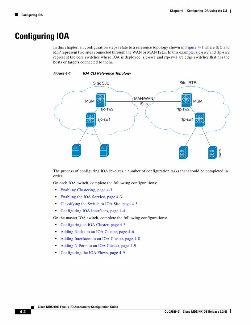
Chapter 4 Configuring IOA Using the CLI Configuring IOA
Configuring IOAIn this chapter, all configuration steps relate to a reference topology shown in Figure 4-1 where SJC and RTP represent two sites connected through the WAN or MAN ISLs. In this example, sjc-sw2 and rtp-sw2 represent the core switches where IOA is deployed. sjc-sw1 and rtp-sw1 are edge switches that has the hosts or targets connected to them.
Figure 4-1 IOA CLI Reference Topology
2763
72
Site: SJC
MSMMAN/WAN
ISLssjc-sw2
sjc-sw1
Site: RTP
MSM
rtp-sw2
rtp-sw1
The process of configuring IOA involves a number of configuration tasks that should be completed in order.
On each IOA switch, complete the following configurations:
• Enabling Clustering, page 4-3
• Enabling the IOA Service, page 4-3
• Classifying the Switch to IOA Site, page 4-3
• Configuring IOA Interfaces, page 4-4
On the master IOA switch, complete the following configurations:
• Configuring an IOA Cluster, page 4-5
• Adding Nodes to an IOA Cluster, page 4-6
• Adding Interfaces to an IOA Cluster, page 4-8
• Adding N Ports to an IOA Cluster, page 4-9
• Configuring the IOA Flows, page 4-9
4-2Cisco MDS 9000 Family I/O Accelerator Configuration Guide
OL-27639-01, Cisco MDS NX-OS Release 5.2(6)
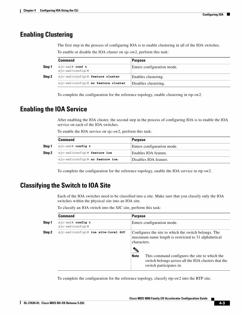
Chapter 4 Configuring IOA Using the CLIConfiguring IOA
Enabling ClusteringThe first step in the process of configuring IOA is to enable clustering in all of the IOA switches.
To enable or disable the IOA cluster on sjc-sw2, perform this task:
Command Purpose
Step 1 sjc-sw2# conf tsjc-sw2(config)#
Enters configuration mode.
Step 2 sjc-sw2(config)# feature cluster Enables clustering.
sjc-sw2(config)# no feature cluster Disables clustering.
To complete the configuration for the reference topology, enable clustering in rtp-sw2.
Enabling the IOA ServiceAfter enabling the IOA cluster, the second step in the process of configuring IOA is to enable the IOA service on each of the IOA switches.
To enable the IOA service on sjc-sw2, perform this task:
Command Purpose
Step 1 sjc-sw2# config t Enters configuration mode.
Step 2 sjc-sw2(config)# feature ioa Enables IOA feature.
sjc-sw2(config)# no feature ioa Disables IOA feature.
To complete the configuration for the reference topology, enable the IOA service in rtp-sw2.
Classifying the Switch to IOA SiteEach of the IOA switches need to be classified into a site. Make sure that you classify only the IOA switches within the physical site into an IOA site.
To classify an IOA switch into the SJC site, perform this task:
Command Purpose
Step 1 sjc-sw2# config tsjc-sw2(config)#
Enters configuration mode.
Step 2 sjc-sw2(config)# ioa site-local SJC Configures the site to which the switch belongs. The maximum name length is restricted to 31 alphabetical characters.
Note This command configures the site to which the switch belongs across all the IOA clusters that the switch participates in.
To complete the configuration for the reference topology, classify rtp-sw2 into the RTP site.
4-3Cisco MDS 9000 Family I/O Accelerator Configuration Guide
OL-27639-01, Cisco MDS NX-OS Release 5.2(6)
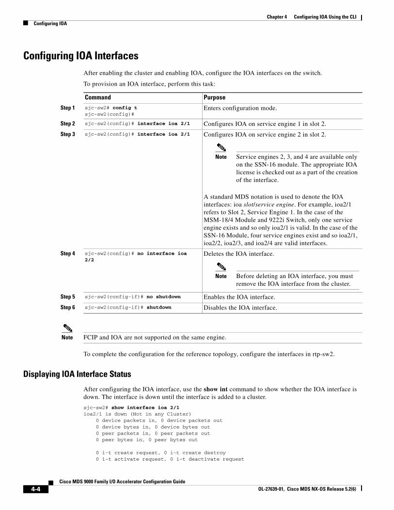
Chapter 4 Configuring IOA Using the CLI Configuring IOA
Configuring IOA InterfacesAfter enabling the cluster and enabling IOA, configure the IOA interfaces on the switch.
To provision an IOA interface, perform this task:
Command Purpose
Step 1 sjc-sw2# config tsjc-sw2(config)#
Enters configuration mode.
Step 2 sjc-sw2(config)# interface ioa 2/1 Configures IOA on service engine 1 in slot 2.
Step 3 sjc-sw2(config)# interface ioa 2/1 Configures IOA on service engine 2 in slot 2.
Note Service engines 2, 3, and 4 are available only on the SSN-16 module. The appropriate IOA license is checked out as a part of the creation of the interface.
A standard MDS notation is used to denote the IOA interfaces: ioa slot/service engine. For example, ioa2/1 refers to Slot 2, Service Engine 1. In the case of the MSM-18/4 Module and 9222i Switch, only one service engine exists and so only ioa2/1 is valid. In the case of the SSN-16 Module, four service engines exist and so ioa2/1, ioa2/2, ioa2/3, and ioa2/4 are valid interfaces.
Step 4 sjc-sw2(config)# no interface ioa 2/2
Deletes the IOA interface.
Note Before deleting an IOA interface, you must remove the IOA interface from the cluster.
Step 5 sjc-sw2(config-if)# no shutdown Enables the IOA interface.
Step 6 sjc-sw2(config-if)# shutdown Disables the IOA interface.
Note FCIP and IOA are not supported on the same engine.
To complete the configuration for the reference topology, configure the interfaces in rtp-sw2.
Displaying IOA Interface Status
After configuring the IOA interface, use the show int command to show whether the IOA interface is down. The interface is down until the interface is added to a cluster.
sjc-sw2# show interface ioa 2/1ioa2/1 is down (Not in any Cluster) 0 device packets in, 0 device packets out 0 device bytes in, 0 device bytes out 0 peer packets in, 0 peer packets out 0 peer bytes in, 0 peer bytes out
0 i-t create request, 0 i-t create destroy 0 i-t activate request, 0 i-t deactivate request
4-4Cisco MDS 9000 Family I/O Accelerator Configuration Guide
OL-27639-01, Cisco MDS NX-OS Release 5.2(6)
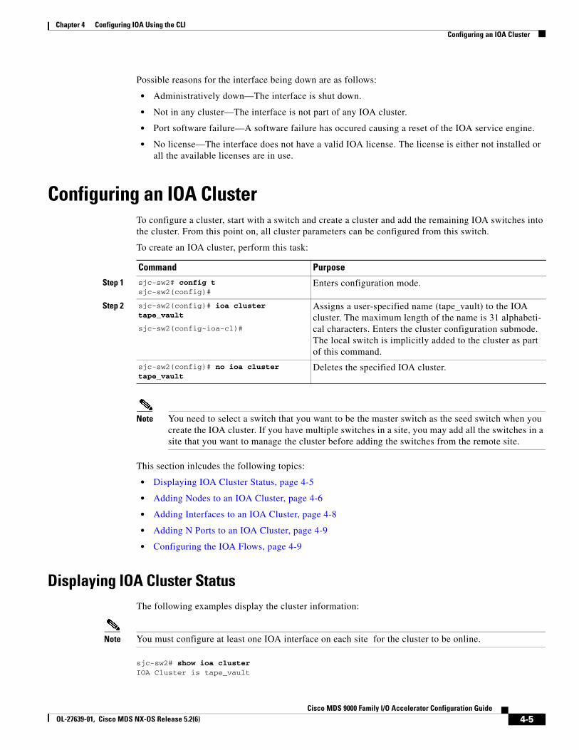
Chapter 4 Configuring IOA Using the CLIConfiguring an IOA Cluster
Possible reasons for the interface being down are as follows:
• Administratively down—The interface is shut down.
• Not in any cluster—The interface is not part of any IOA cluster.
• Port software failure—A software failure has occured causing a reset of the IOA service engine.
• No license—The interface does not have a valid IOA license. The license is either not installed or all the available licenses are in use.
Configuring an IOA Cluster To configure a cluster, start with a switch and create a cluster and add the remaining IOA switches into the cluster. From this point on, all cluster parameters can be configured from this switch.
To create an IOA cluster, perform this task:
Command Purpose
Step 1 sjc-sw2# config tsjc-sw2(config)#
Enters configuration mode.
Step 2 sjc-sw2(config)# ioa cluster tape_vault
sjc-sw2(config-ioa-cl)#
Assigns a user-specified name (tape_vault) to the IOA cluster. The maximum length of the name is 31 alphabeti-cal characters. Enters the cluster configuration submode. The local switch is implicitly added to the cluster as part of this command.
sjc-sw2(config)# no ioa cluster tape_vault
Deletes the specified IOA cluster.
Note You need to select a switch that you want to be the master switch as the seed switch when you create the IOA cluster. If you have multiple switches in a site, you may add all the switches in a site that you want to manage the cluster before adding the switches from the remote site.
This section inlcudes the following topics:
• Displaying IOA Cluster Status, page 4-5
• Adding Nodes to an IOA Cluster, page 4-6
• Adding Interfaces to an IOA Cluster, page 4-8
• Adding N Ports to an IOA Cluster, page 4-9
• Configuring the IOA Flows, page 4-9
Displaying IOA Cluster StatusThe following examples display the cluster information:
Note You must configure at least one IOA interface on each site for the cluster to be online.
sjc-sw2# show ioa cluster IOA Cluster is tape_vault
4-5Cisco MDS 9000 Family I/O Accelerator Configuration Guide
OL-27639-01, Cisco MDS NX-OS Release 5.2(6)
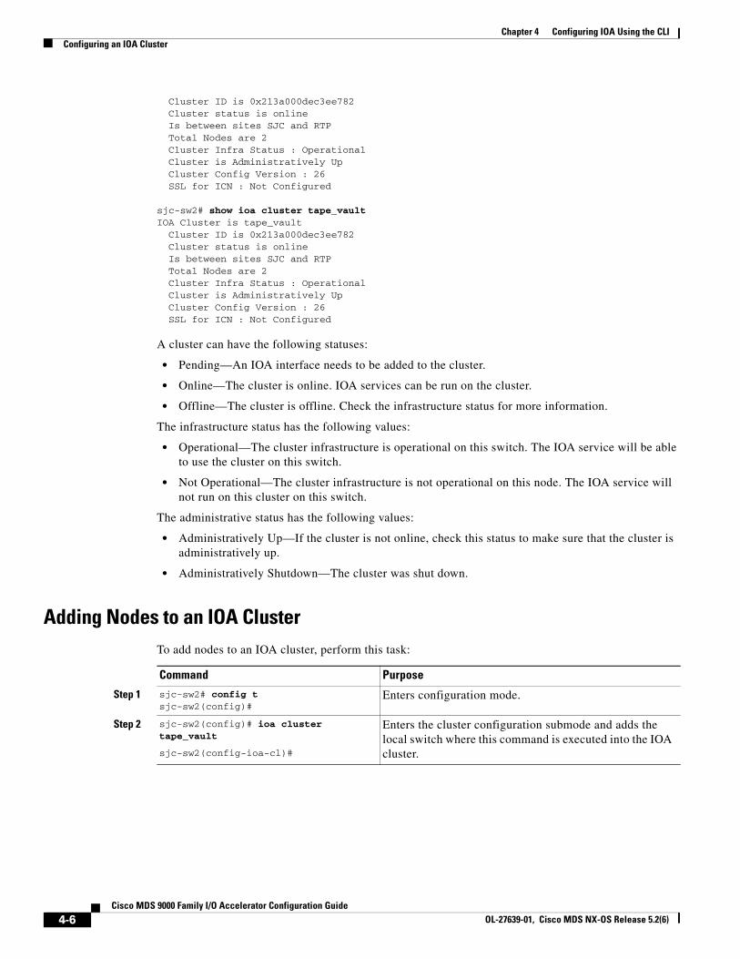
Chapter 4 Configuring IOA Using the CLI Configuring an IOA Cluster
Cluster ID is 0x213a000dec3ee782 Cluster status is online Is between sites SJC and RTP Total Nodes are 2 Cluster Infra Status : Operational Cluster is Administratively Up Cluster Config Version : 26 SSL for ICN : Not Configured
sjc-sw2# show ioa cluster tape_vaultIOA Cluster is tape_vault Cluster ID is 0x213a000dec3ee782 Cluster status is online Is between sites SJC and RTP Total Nodes are 2 Cluster Infra Status : Operational Cluster is Administratively Up Cluster Config Version : 26 SSL for ICN : Not Configured
A cluster can have the following statuses:
• Pending—An IOA interface needs to be added to the cluster.
• Online—The cluster is online. IOA services can be run on the cluster.
• Offline—The cluster is offline. Check the infrastructure status for more information.
The infrastructure status has the following values:
• Operational—The cluster infrastructure is operational on this switch. The IOA service will be able to use the cluster on this switch.
• Not Operational—The cluster infrastructure is not operational on this node. The IOA service will not run on this cluster on this switch.
The administrative status has the following values:
• Administratively Up—If the cluster is not online, check this status to make sure that the cluster is administratively up.
• Administratively Shutdown—The cluster was shut down.
Adding Nodes to an IOA ClusterTo add nodes to an IOA cluster, perform this task:
Command Purpose
Step 1 sjc-sw2# config tsjc-sw2(config)#
Enters configuration mode.
Step 2 sjc-sw2(config)# ioa cluster tape_vault
sjc-sw2(config-ioa-cl)#
Enters the cluster configuration submode and adds the local switch where this command is executed into the IOA cluster.
4-6Cisco MDS 9000 Family I/O Accelerator Configuration Guide
OL-27639-01, Cisco MDS NX-OS Release 5.2(6)
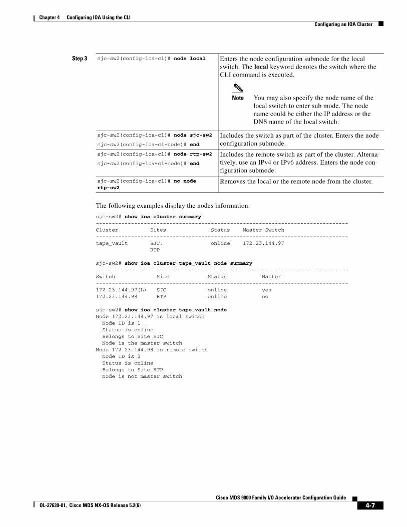
Chapter 4 Configuring IOA Using the CLIConfiguring an IOA Cluster
The following examples display the nodes information:
sjc-sw2# show ioa cluster summary -------------------------------------------------------------------------------Cluster Sites Status Master Switch-------------------------------------------------------------------------------tape_vault SJC, online 172.23.144.97 RTP
sjc-sw2# show ioa cluster tape_vault node summary-------------------------------------------------------------------------------Switch Site Status Master-------------------------------------------------------------------------------172.23.144.97(L) SJC online yes172.23.144.98 RTP online no
sjc-sw2# show ioa cluster tape_vault nodeNode 172.23.144.97 is local switch Node ID is 1 Status is online Belongs to Site SJC Node is the master switchNode 172.23.144.98 is remote switch Node ID is 2 Status is online Belongs to Site RTP Node is not master switch
Step 3 sjc-sw2(config-ioa-cl)# node local Enters the node configuration submode for the local switch. The local keyword denotes the switch where the CLI command is executed.
Note You may also specify the node name of the local switch to enter sub mode. The node name could be either the IP address or the DNS name of the local switch.
sjc-sw2(config-ioa-cl)# node sjc-sw2
sjc-sw2(config-ioa-cl-node)# end
Includes the switch as part of the cluster. Enters the node configuration submode.
sjc-sw2(config-ioa-cl)# node rtp-sw2
sjc-sw2(config-ioa-cl-node)# end
Includes the remote switch as part of the cluster. Alterna-tively, use an IPv4 or IPv6 address. Enters the node con-figuration submode.
sjc-sw2(config-ioa-cl)# no node rtp-sw2
Removes the local or the remote node from the cluster.
4-7Cisco MDS 9000 Family I/O Accelerator Configuration Guide
OL-27639-01, Cisco MDS NX-OS Release 5.2(6)
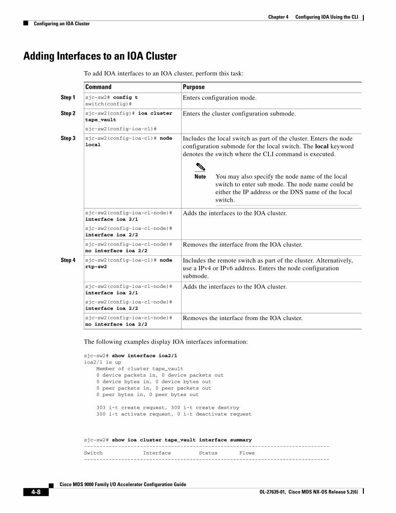
Chapter 4 Configuring IOA Using the CLI Configuring an IOA Cluster
Adding Interfaces to an IOA ClusterTo add IOA interfaces to an IOA cluster, perform this task:
Command Purpose
Step 1 sjc-sw2# config tswitch(config)#
Enters configuration mode.
Step 2 sjc-sw2(config)# ioa cluster tape_vault
sjc-sw2(config-ioa-cl)#
Enters the cluster configuration submode.
Step 3 sjc-sw2(config-ioa-cl)# node local
Includes the local switch as part of the cluster. Enters the node configuration submode for the local switch. The local keyword denotes the switch where the CLI command is executed.
Note You may also specify the node name of the local switch to enter sub mode. The node name could be either the IP address or the DNS name of the local switch.
sjc-sw2(config-ioa-cl-node)# interface ioa 2/1
sjc-sw2(config-ioa-cl-node)# interface ioa 2/2
Adds the interfaces to the IOA cluster.
sjc-sw2(config-ioa-cl-node)# no interface ioa 2/2
Removes the interface from the IOA cluster.
Step 4 sjc-sw2(config-ioa-cl)# node rtp-sw2
Includes the remote switch as part of the cluster. Alternatively, use a IPv4 or IPv6 address. Enters the node configuration submode.
sjc-sw2(config-ioa-cl-node)# interface ioa 2/1
sjc-sw2(config-ioa-cl-node)# interface ioa 2/2
Adds the interfaces to the IOA cluster.
sjc-sw2(config-ioa-cl-node)# no interface ioa 2/2
Removes the interface from the IOA cluster.
The following examples display IOA interfaces information:
sjc-sw2# show interface ioa2/1ioa2/1 is up Member of cluster tape_vault 0 device packets in, 0 device packets out 0 device bytes in, 0 device bytes out 0 peer packets in, 0 peer packets out 0 peer bytes in, 0 peer bytes out
303 i-t create request, 300 i-t create destroy 300 i-t activate request, 0 i-t deactivate request
sjc-sw2# show ioa cluster tape_vault interface summary -------------------------------------------------------------------------------Switch Interface Status Flows-------------------------------------------------------------------------------
4-8Cisco MDS 9000 Family I/O Accelerator Configuration Guide
OL-27639-01, Cisco MDS NX-OS Release 5.2(6)
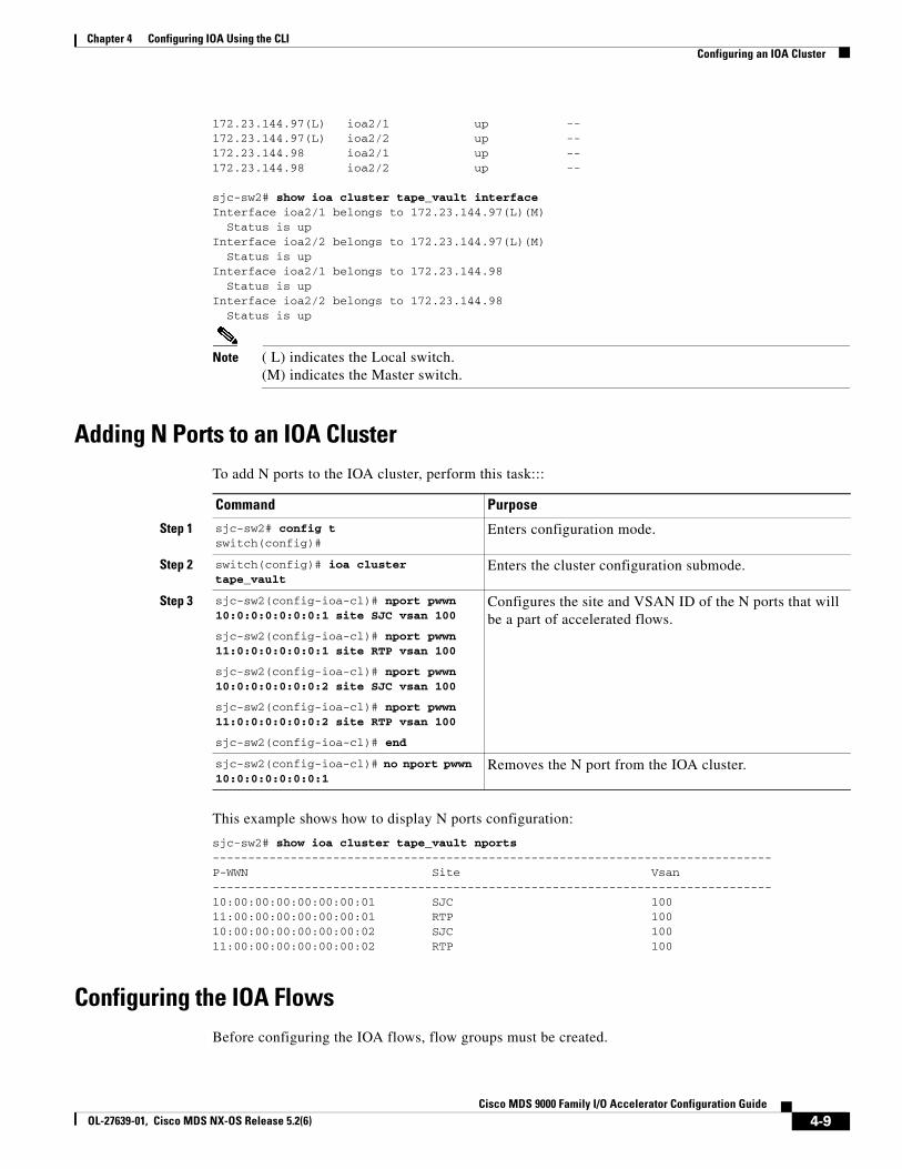
Chapter 4 Configuring IOA Using the CLIConfiguring an IOA Cluster
172.23.144.97(L) ioa2/1 up --172.23.144.97(L) ioa2/2 up --172.23.144.98 ioa2/1 up --172.23.144.98 ioa2/2 up --
sjc-sw2# show ioa cluster tape_vault interface Interface ioa2/1 belongs to 172.23.144.97(L)(M) Status is up Interface ioa2/2 belongs to 172.23.144.97(L)(M) Status is up Interface ioa2/1 belongs to 172.23.144.98 Status is up Interface ioa2/2 belongs to 172.23.144.98 Status is up
Note ( L) indicates the Local switch.(M) indicates the Master switch.
Adding N Ports to an IOA ClusterTo add N ports to the IOA cluster, perform this task:::
Command Purpose
Step 1 sjc-sw2# config tswitch(config)#
Enters configuration mode.
Step 2 switch(config)# ioa cluster tape_vault
Enters the cluster configuration submode.
Step 3 sjc-sw2(config-ioa-cl)# nport pwwn 10:0:0:0:0:0:0:1 site SJC vsan 100
sjc-sw2(config-ioa-cl)# nport pwwn 11:0:0:0:0:0:0:1 site RTP vsan 100
sjc-sw2(config-ioa-cl)# nport pwwn 10:0:0:0:0:0:0:2 site SJC vsan 100
sjc-sw2(config-ioa-cl)# nport pwwn 11:0:0:0:0:0:0:2 site RTP vsan 100
sjc-sw2(config-ioa-cl)# end
Configures the site and VSAN ID of the N ports that will be a part of accelerated flows.
sjc-sw2(config-ioa-cl)# no nport pwwn 10:0:0:0:0:0:0:1
Removes the N port from the IOA cluster.
This example shows how to display N ports configuration:
sjc-sw2# show ioa cluster tape_vault nports-------------------------------------------------------------------------------P-WWN Site Vsan-------------------------------------------------------------------------------10:00:00:00:00:00:00:01 SJC 10011:00:00:00:00:00:00:01 RTP 10010:00:00:00:00:00:00:02 SJC 10011:00:00:00:00:00:00:02 RTP 100
Configuring the IOA FlowsBefore configuring the IOA flows, flow groups must be created.
4-9Cisco MDS 9000 Family I/O Accelerator Configuration Guide
OL-27639-01, Cisco MDS NX-OS Release 5.2(6)
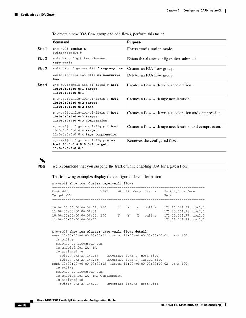
Chapter 4 Configuring IOA Using the CLI Configuring an IOA Cluster
To create a new IOA flow group and add flows, perform this task::
Command Purpose
Step 1 sjc-sw2# config tswitch(config)#
Enters configuration mode.
Step 2 switch(config)# ioa cluster tape_vault
Enters the cluster configuration submode.
Step 3 switch(config-ioa-cl)# flowgroup tsm Creates an IOA flow group.
switch(config-ioa-cl)# no flowgroup tsm
Deletes an IOA flow group.
Step 4 sjc-sw2(config-ioa-cl-flgrp)# host 10:0:0:0:0:0:0:1 target 11:0:0:0:0:0:0:1
Creates a flow with write acceleration.
sjc-sw2(config-ioa-cl-flgrp)# host 10:0:0:0:0:0:0:2 target 11:0:0:0:0:0:0:2 tape
Creates a flow with tape acceleration.
sjc-sw2(config-ioa-cl-flgrp)# host 10:0:0:0:0:0:0:3 target 11:0:0:0:0:0:0:3 compression
Creates a flow with write acceleration and compression.
sjc-sw2(config-ioa-cl-flgrp)# host 10:0:0:0:0:0:0:4 target 11:0:0:0:0:0:0:4 tape compression
Creates a flow with tape acceleration, and compression.
sjc-sw2(config-ioa-cl-flgrp)# no host 10:0:0:0:0:0:0:1 target 11:0:0:0:0:0:0:1
Removes the configured flow.
Note We recommend that you suspend the traffic while enabling IOA for a given flow.
The following examples display the configured flow information:
sjc-sw2# show ioa cluster tape_vault flows-------------------------------------------------------------------------------Host WWN, VSAN WA TA Comp Status Switch,InterfaceTarget WWN Pair-------------------------------------------------------------------------------
10:00:00:00:00:00:00:01, 100 Y Y N online 172.23.144.97, ioa2/111:00:00:00:00:00:00:01 172.23.144.98, ioa2/1 10:00:00:00:00:00:00:02, 100 Y Y Y online 172.23.144.97, ioa2/211:00:00:00:00:00:00:02 172.23.144.98, ioa2/2
sjc-sw2# show ioa cluster tape_vault flows detail Host 10:00:00:00:00:00:00:01, Target 11:00:00:00:00:00:00:01, VSAN 100 Is online Belongs to flowgroup tsm Is enabled for WA, TA Is assigned to Switch 172.23.144.97 Interface ioa2/1 (Host Site) Switch 172.23.144.98 Interface ioa2/1 (Target Site)Host 10:00:00:00:00:00:00:02, Target 11:00:00:00:00:00:00:02, VSAN 100 Is online Belongs to flowgroup tsm Is enabled for WA, TA, Compression Is assigned to Switch 172.23.144.97 Interface ioa2/2 (Host Site)
4-10Cisco MDS 9000 Family I/O Accelerator Configuration Guide
OL-27639-01, Cisco MDS NX-OS Release 5.2(6)
Chapter 4 Configuring IOA Using the CLIIOA Flow Setup Wizard
Switch 172.23.144.98 Interface ioa2/2 (Target Site)
IOA Flow Setup WizardYou can use the IOA Flow Setup Wizard to simplify the provisioning of flows especially when there are many flows to provision, and when you add, remove, or replace host HBAs, tape drives or storage controllers.
This section includes the following topics:
• Prerequisites for IOA Flow Setup Wizard, page 4-11
• Using the IOA Flow Setup Wizard, page 4-11
Prerequisites for IOA Flow Setup WizardThe following prerequisites must be met before you can invoke the IOA Flow Setup Wizard:
• All of the N ports of both initiators and targets that need to be accelerated must be online.
• The zoning configuration must already be in place to permit the flows that need to communicate with each other. If you are replacing a host HBA, you must update the zoning configuration to remove the faulty HBA and to add the new HBA before you invoke the IOA Flow Setup Wizard.
Using the IOA Flow Setup WizardTo configure flows using the Flow Setup Wizard, follow these steps:
Step 1 Invoke the Flow Setup Wizard on a specific VSAN.
sjc-sw1# ioa flow-setup cluster tape_vault flowgroup repln-fg vsan 100
In the case of an IVR deployment, you can enter the following CLI command on an IVR border switch where IOA is deployed:
sjc-sw1# ioa ivr flow-setup cluster tape_vault flowgroup repln-fg
The wizard processes the active zone set for the VSAN and creates a set of candidate flows. When you use the ivr flow-setup command, the active IVR zone set is considered. The zone set may have local flows as well as flows that traverse across sites. The IOA Flow Setup Wizard runs through a series of steps as listed in this procedure to prune the list to capture only the flows that traverse across the sites that need to be accelerated.
Step 2 Classify the switches in the candidate switch list into appropriate sites.
This step is only for those switches where none of the hosts or targets have been configured yet for acceleration. From the flows in the active zone set, a candidate switch list is prepared based on where the hosts and targets are logged into.
The following switches need to be classified into appropriate sites-------------------------------------------------------------------------------Do you want to classify sjc-sw1 into site sjc or rtp [sjc] Do you want to classify 172.23.144.96 into site sjc or rtp [sjc] rtp
The candidate flow list is now pruned to contain only the inter-site flows that need to be accelerated.
4-11Cisco MDS 9000 Family I/O Accelerator Configuration Guide
OL-27639-01, Cisco MDS NX-OS Release 5.2(6)
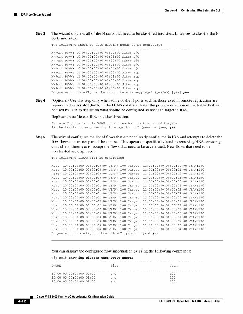
Chapter 4 Configuring IOA Using the CLI IOA Flow Setup Wizard
Step 3 The wizard displays all of the N ports that need to be classified into sites. Enter yes to classify the N ports into sites.
The following nport to site mapping needs to be configured-------------------------------------------------------------------------------N-Port PWWN: 10:00:00:00:00:00:00:00 Site: sjcN-Port PWWN: 10:00:00:00:00:00:01:00 Site: sjcN-Port PWWN: 10:00:00:00:00:00:02:00 Site: sjcN-Port PWWN: 10:00:00:00:00:00:03:00 Site: sjcN-Port PWWN: 10:00:00:00:00:00:04:00 Site: sjcN-Port PWWN: 11:00:00:00:00:00:00:00 Site: rtpN-Port PWWN: 11:00:00:00:00:00:01:00 Site: rtpN-Port PWWN: 11:00:00:00:00:00:02:00 Site: rtpN-Port PWWN: 11:00:00:00:00:00:03:00 Site: rtpN-Port PWWN: 11:00:00:00:00:00:04:00 Site: rtpDo you want to configure the n-port to site mappings? (yes/no) [yes] yes
Step 4 (Optional) Use this step only when some of the N ports such as those used in remote replication are represented as scsi-fcp(both) in the FCNS database. Enter the primary direction of the traffic that will be used by IOA to decide on what should be configured as host and target in IOA.
Replication traffic can flow in either direction.
Certain N-ports in this VSAN can act as both initiator and targetsIs the traffic flow primarily from sjc to rtp? (yes/no) [yes] yes
Step 5 The wizard configures the list of flows that are not already configured in IOA and attempts to delete the IOA flows that are not part of the zone set. This operation specifically handles removing HBAs or storage controllers. Enter yes to accept the flows that need to be accelerated. New flows that need to be accelerated are displayed.
The following flows will be configured-------------------------------------------------------------------------------Host: 10:00:00:00:00:00:00:00 VSAN: 100 Target: 11:00:00:00:00:00:00:00 VSAN:100Host: 10:00:00:00:00:00:00:00 VSAN: 100 Target: 11:00:00:00:00:00:01:00 VSAN:100Host: 10:00:00:00:00:00:00:00 VSAN: 100 Target: 11:00:00:00:00:00:02:00 VSAN:100Host: 10:00:00:00:00:00:00:00 VSAN: 100 Target: 11:00:00:00:00:00:03:00 VSAN:100Host: 10:00:00:00:00:00:01:00 VSAN: 100 Target: 11:00:00:00:00:00:00:00 VSAN:100Host: 10:00:00:00:00:00:01:00 VSAN: 100 Target: 11:00:00:00:00:00:01:00 VSAN:100Host: 10:00:00:00:00:00:01:00 VSAN: 100 Target: 11:00:00:00:00:00:02:00 VSAN:100Host: 10:00:00:00:00:00:01:00 VSAN: 100 Target: 11:00:00:00:00:00:03:00 VSAN:100Host: 10:00:00:00:00:00:02:00 VSAN: 100 Target: 11:00:00:00:00:00:00:00 VSAN:100Host: 10:00:00:00:00:00:02:00 VSAN: 100 Target: 11:00:00:00:00:00:01:00 VSAN:100Host: 10:00:00:00:00:00:02:00 VSAN: 100 Target: 11:00:00:00:00:00:02:00 VSAN:100Host: 10:00:00:00:00:00:02:00 VSAN: 100 Target: 11:00:00:00:00:00:03:00 VSAN:100Host: 10:00:00:00:00:00:03:00 VSAN: 100 Target: 11:00:00:00:00:00:00:00 VSAN:100Host: 10:00:00:00:00:00:03:00 VSAN: 100 Target: 11:00:00:00:00:00:01:00 VSAN:100Host: 10:00:00:00:00:00:03:00 VSAN: 100 Target: 11:00:00:00:00:00:02:00 VSAN:100Host: 10:00:00:00:00:00:03:00 VSAN: 100 Target: 11:00:00:00:00:00:03:00 VSAN:100Host: 10:00:00:00:00:00:04:00 VSAN: 100 Target: 11:00:00:00:00:00:04:00 VSAN:100Do you want to configure these flows? (yes/no) [yes] yes
You can display the configured flow information by using the following commands:
sjc-sw1# show ioa cluster tape_vault nports -------------------------------------------------------------------------------P-WWN Site Vsan-------------------------------------------------------------------------------10:00:00:00:00:00:00:00 sjc 10010:00:00:00:00:00:01:00 sjc 10010:00:00:00:00:00:02:00 sjc 100
4-12Cisco MDS 9000 Family I/O Accelerator Configuration Guide
OL-27639-01, Cisco MDS NX-OS Release 5.2(6)
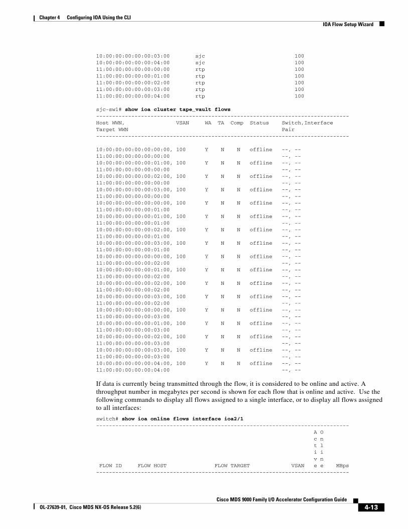
Chapter 4 Configuring IOA Using the CLIIOA Flow Setup Wizard
10:00:00:00:00:00:03:00 sjc 10010:00:00:00:00:00:04:00 sjc 10011:00:00:00:00:00:00:00 rtp 10011:00:00:00:00:00:01:00 rtp 10011:00:00:00:00:00:02:00 rtp 10011:00:00:00:00:00:03:00 rtp 10011:00:00:00:00:00:04:00 rtp 100
sjc-sw1# show ioa cluster tape_vault flows -------------------------------------------------------------------------------Host WWN, VSAN WA TA Comp Status Switch,InterfaceTarget WWN Pair------------------------------------------------------------------------------- 10:00:00:00:00:00:00:00, 100 Y N N offline --, --11:00:00:00:00:00:00:00 --, -- 10:00:00:00:00:00:01:00, 100 Y N N offline --, --11:00:00:00:00:00:00:00 --, -- 10:00:00:00:00:00:02:00, 100 Y N N offline --, --11:00:00:00:00:00:00:00 --, -- 10:00:00:00:00:00:03:00, 100 Y N N offline --, --11:00:00:00:00:00:00:00 --, -- 10:00:00:00:00:00:00:00, 100 Y N N offline --, --11:00:00:00:00:00:01:00 --, -- 10:00:00:00:00:00:01:00, 100 Y N N offline --, --11:00:00:00:00:00:01:00 --, -- 10:00:00:00:00:00:02:00, 100 Y N N offline --, --11:00:00:00:00:00:01:00 --, -- 10:00:00:00:00:00:03:00, 100 Y N N offline --, --11:00:00:00:00:00:01:00 --, -- 10:00:00:00:00:00:00:00, 100 Y N N offline --, --11:00:00:00:00:00:02:00 --, -- 10:00:00:00:00:00:01:00, 100 Y N N offline --, --11:00:00:00:00:00:02:00 --, -- 10:00:00:00:00:00:02:00, 100 Y N N offline --, --11:00:00:00:00:00:02:00 --, -- 10:00:00:00:00:00:03:00, 100 Y N N offline --, --11:00:00:00:00:00:02:00 --, -- 10:00:00:00:00:00:00:00, 100 Y N N offline --, --11:00:00:00:00:00:03:00 --, -- 10:00:00:00:00:00:01:00, 100 Y N N offline --, --11:00:00:00:00:00:03:00 --, -- 10:00:00:00:00:00:02:00, 100 Y N N offline --, --11:00:00:00:00:00:03:00 --, -- 10:00:00:00:00:00:03:00, 100 Y N N offline --, --11:00:00:00:00:00:03:00 --, -- 10:00:00:00:00:00:04:00, 100 Y N N offline --, --11:00:00:00:00:00:04:00 --, --
If data is currently being transmitted through the flow, it is considered to be online and active. A throughput number in megabytes per second is shown for each flow that is online and active. Use the following commands to display all flows assigned to a single interface, or to display all flows assigned to all interfaces:
switch# show ioa online flows interface ioa2/1------------------------------------------------------------------------------- A O c n t l i i v n FLOW ID FLOW HOST FLOW TARGET VSAN e e MBps-------------------------------------------------------------------------------
4-13Cisco MDS 9000 Family I/O Accelerator Configuration Guide
OL-27639-01, Cisco MDS NX-OS Release 5.2(6)
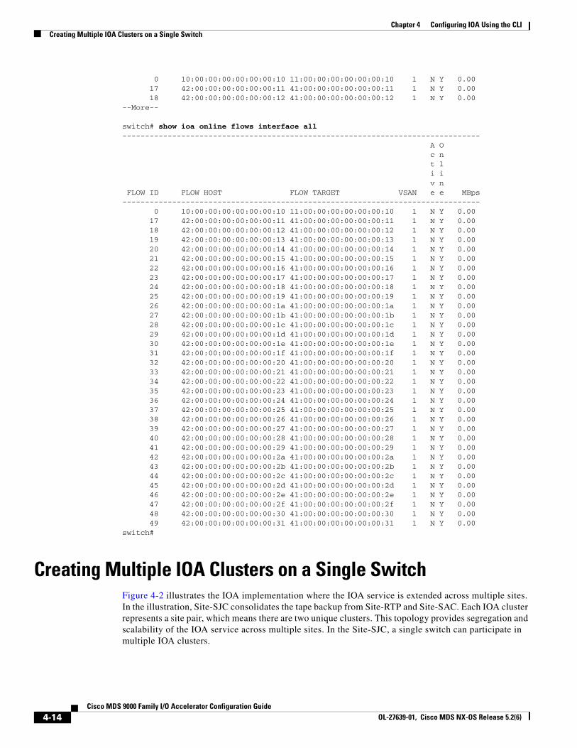
Chapter 4 Configuring IOA Using the CLI Creating Multiple IOA Clusters on a Single Switch
0 10:00:00:00:00:00:00:10 11:00:00:00:00:00:00:10 1 N Y 0.00 17 42:00:00:00:00:00:00:11 41:00:00:00:00:00:00:11 1 N Y 0.00 18 42:00:00:00:00:00:00:12 41:00:00:00:00:00:00:12 1 N Y 0.00--More--
switch# show ioa online flows interface all------------------------------------------------------------------------------- A O c n t l i i v n FLOW ID FLOW HOST FLOW TARGET VSAN e e MBps------------------------------------------------------------------------------- 0 10:00:00:00:00:00:00:10 11:00:00:00:00:00:00:10 1 N Y 0.00 17 42:00:00:00:00:00:00:11 41:00:00:00:00:00:00:11 1 N Y 0.00 18 42:00:00:00:00:00:00:12 41:00:00:00:00:00:00:12 1 N Y 0.00 19 42:00:00:00:00:00:00:13 41:00:00:00:00:00:00:13 1 N Y 0.00 20 42:00:00:00:00:00:00:14 41:00:00:00:00:00:00:14 1 N Y 0.00 21 42:00:00:00:00:00:00:15 41:00:00:00:00:00:00:15 1 N Y 0.00 22 42:00:00:00:00:00:00:16 41:00:00:00:00:00:00:16 1 N Y 0.00 23 42:00:00:00:00:00:00:17 41:00:00:00:00:00:00:17 1 N Y 0.00 24 42:00:00:00:00:00:00:18 41:00:00:00:00:00:00:18 1 N Y 0.00 25 42:00:00:00:00:00:00:19 41:00:00:00:00:00:00:19 1 N Y 0.00 26 42:00:00:00:00:00:00:1a 41:00:00:00:00:00:00:1a 1 N Y 0.00 27 42:00:00:00:00:00:00:1b 41:00:00:00:00:00:00:1b 1 N Y 0.00 28 42:00:00:00:00:00:00:1c 41:00:00:00:00:00:00:1c 1 N Y 0.00 29 42:00:00:00:00:00:00:1d 41:00:00:00:00:00:00:1d 1 N Y 0.00 30 42:00:00:00:00:00:00:1e 41:00:00:00:00:00:00:1e 1 N Y 0.00 31 42:00:00:00:00:00:00:1f 41:00:00:00:00:00:00:1f 1 N Y 0.00 32 42:00:00:00:00:00:00:20 41:00:00:00:00:00:00:20 1 N Y 0.00 33 42:00:00:00:00:00:00:21 41:00:00:00:00:00:00:21 1 N Y 0.00 34 42:00:00:00:00:00:00:22 41:00:00:00:00:00:00:22 1 N Y 0.00 35 42:00:00:00:00:00:00:23 41:00:00:00:00:00:00:23 1 N Y 0.00 36 42:00:00:00:00:00:00:24 41:00:00:00:00:00:00:24 1 N Y 0.00 37 42:00:00:00:00:00:00:25 41:00:00:00:00:00:00:25 1 N Y 0.00 38 42:00:00:00:00:00:00:26 41:00:00:00:00:00:00:26 1 N Y 0.00 39 42:00:00:00:00:00:00:27 41:00:00:00:00:00:00:27 1 N Y 0.00 40 42:00:00:00:00:00:00:28 41:00:00:00:00:00:00:28 1 N Y 0.00 41 42:00:00:00:00:00:00:29 41:00:00:00:00:00:00:29 1 N Y 0.00 42 42:00:00:00:00:00:00:2a 41:00:00:00:00:00:00:2a 1 N Y 0.00 43 42:00:00:00:00:00:00:2b 41:00:00:00:00:00:00:2b 1 N Y 0.00 44 42:00:00:00:00:00:00:2c 41:00:00:00:00:00:00:2c 1 N Y 0.00 45 42:00:00:00:00:00:00:2d 41:00:00:00:00:00:00:2d 1 N Y 0.00 46 42:00:00:00:00:00:00:2e 41:00:00:00:00:00:00:2e 1 N Y 0.00 47 42:00:00:00:00:00:00:2f 41:00:00:00:00:00:00:2f 1 N Y 0.00 48 42:00:00:00:00:00:00:30 41:00:00:00:00:00:00:30 1 N Y 0.00 49 42:00:00:00:00:00:00:31 41:00:00:00:00:00:00:31 1 N Y 0.00switch#
Creating Multiple IOA Clusters on a Single SwitchFigure 4-2 illustrates the IOA implementation where the IOA service is extended across multiple sites. In the illustration, Site-SJC consolidates the tape backup from Site-RTP and Site-SAC. Each IOA cluster represents a site pair, which means there are two unique clusters. This topology provides segregation and scalability of the IOA service across multiple sites. In the Site-SJC, a single switch can participate in multiple IOA clusters.
4-14Cisco MDS 9000 Family I/O Accelerator Configuration Guide
OL-27639-01, Cisco MDS NX-OS Release 5.2(6)
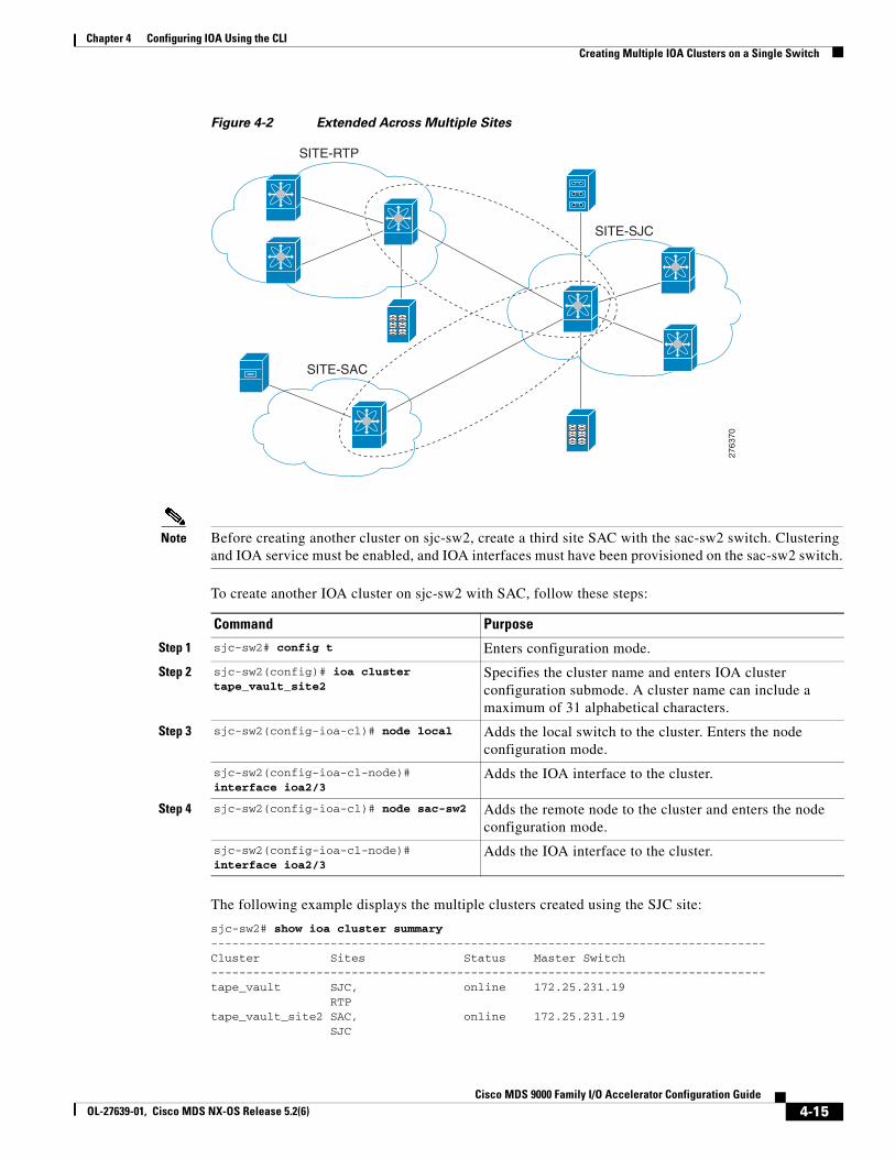
Chapter 4 Configuring IOA Using the CLICreating Multiple IOA Clusters on a Single Switch
Figure 4-2 Extended Across Multiple Sites
SITE-RTP
SITE-SAC
2763
70
SITE-SJC
Note Before creating another cluster on sjc-sw2, create a third site SAC with the sac-sw2 switch. Clustering and IOA service must be enabled, and IOA interfaces must have been provisioned on the sac-sw2 switch.
To create another IOA cluster on sjc-sw2 with SAC, follow these steps:
Command Purpose
Step 1 sjc-sw2# config t Enters configuration mode.
Step 2 sjc-sw2(config)# ioa cluster tape_vault_site2
Specifies the cluster name and enters IOA cluster configuration submode. A cluster name can include a maximum of 31 alphabetical characters.
Step 3 sjc-sw2(config-ioa-cl)# node local Adds the local switch to the cluster. Enters the node configuration mode.
sjc-sw2(config-ioa-cl-node)# interface ioa2/3
Adds the IOA interface to the cluster.
Step 4 sjc-sw2(config-ioa-cl)# node sac-sw2 Adds the remote node to the cluster and enters the node configuration mode.
sjc-sw2(config-ioa-cl-node)# interface ioa2/3
Adds the IOA interface to the cluster.
The following example displays the multiple clusters created using the SJC site:
sjc-sw2# show ioa cluster summary -------------------------------------------------------------------------------Cluster Sites Status Master Switch-------------------------------------------------------------------------------tape_vault SJC, online 172.25.231.19 RTPtape_vault_site2 SAC, online 172.25.231.19 SJC
4-15Cisco MDS 9000 Family I/O Accelerator Configuration Guide
OL-27639-01, Cisco MDS NX-OS Release 5.2(6)
Chapter 4 Configuring IOA Using the CLI Configuring IOA with NPV
Note You need to select a switch that you want to be the master switch as the seed switch when you create the IOA cluster. If you have multiple switches in a site, you add all the switches in a site that you want to manage the cluster before adding the switches from the remote site.
Note In this example, the SJC site may be a natural consolidation point for management, and you may choose a switch from this site as the preferred master switch.
Configuring IOA with NPVYou can use the Cisco MDS 9000 Family I/O Accelerator (IOA) with N port virtualization (NPV) to reduce the number of Fibre Channel domain IDs in SANs. Switches operating in NPV mode does not join a fabric or exchange traffic between NPV core switch links and end devices. You can deploy multiple edge switches without any shortage of domain IDs. NPV is not available in switch mode. To make NPV available on a switch, you must turn on NPV mode.
You can use the Cisco MDS 9000 Family I/O Accelerator (IOA) with N port ID virtualization (NPIV). NPIV efficiently utilizes the HBA ports on the blade servers in a data center and reduces the number of FCIDs assigned to the HBA ports.
The switches are not in NPV mode by default. NPV is supported in the following Cisco MDS 9000 switches:
• Cisco MDS 9124 Multilayer Fabric Switch
• Cisco MDS 9134 Fabric Switch
• Cisco Fabric Switch for HP c-Class BladeSystem
• Cisco Fabric Switch for IBM BladeCenter
Note Configuring IOA with NPV is supported in Cisco NX-OS Release 5.2(2) and later.
Guidelines for Configuring IOA with NPVFollow these guidelines to configure IOA with NPV:
• Enable NPV on Cisco MDS 9124 switch or Cisco MDS 9134 switch.
• Enable NPIV on the NPV core switch.
Note To enable NPV on the NPV device switch, follow the guidelines specified in Cisco MDS 9000 Family NX-OS Interfaces Configuration Guide, Release 5.0(1a).
• You must make sure that the NP link is active.
• You must configure NPV traffic map, F-port PortChannel and multiple NP links.
• Enable IOA and configure IOA cluster on the NPV core switch and on another node in the SAN. The IOA node can reside on any other Cisco MDS switches in the SAN other than the NPV core switch.
• Add IOA interfaces to the cluster.
4-16Cisco MDS 9000 Family I/O Accelerator Configuration Guide
OL-27639-01, Cisco MDS NX-OS Release 5.2(6)
Chapter 4 Configuring IOA Using the CLIConfiguring IOA with NPV
• Add remote node and interface of the remote node.
• Activate the IOA flows with WA, TA, compression as per the requirement.
• You can activate multiple IOA flows and multiple IOA clusters.
• You must enable NPIV on NPV devices if you are using VMware hosts or servers for multiple FDISC, fabric discovery configuration over the same NP link.
• You can use up to 100 hosts with IOA active flows over a single NP link.
• You can use up to 100 hosts with IOA active flows over a FPC (F-port PortChannel)
• Beginning with Cisco MDS 9000 NX-OS Release 5.2(2), features such as FPC, TFPC, and FlexAttach virtual pWWN are supported.
• You can have an IOA node on the NPV core switch and also on any other switches.
Configuring NPIV on an NPV Core Switch, NPV on an NPV Device, and Activating NP Link
The following procedures are used to enable NPV and NPIV:
• Enabling NPIV on the NPV core switch
• Enabling NPV on the NPV device
• Configuring the interfaces connected to the NPV core switch as NP ports
• Configuring the port VSAN for the NP ports
• Configuring NPV link as an F port on the NPV core switch
• Configuring the port VSAN for the F ports
• Configuring the other server and target ports on the NPV device as F ports
Configuring NPIV on the NPV Core Switch
To enable NPIV and NPV, perform this task:
Command Purpose
Step 1 switch# config t Enters configuration mode.
Step 2 switch(config)# feature npiv Enables NPIV mode on the NPV core switch.
Step 3 switch(config)# interface fc 2/1switch(config-if)# switchport mode Fswitch(config-if)# no shutdown
Configures the NPV core switch port as a F port and enables the interface.
Step 4 switch(config)# vsan databaseswitch(config-vsan-db)# vsan 500 interface fc2/1
Configures the port VSANs for the F port on the NPV core switch.
4-17Cisco MDS 9000 Family I/O Accelerator Configuration Guide
OL-27639-01, Cisco MDS NX-OS Release 5.2(6)

Chapter 4 Configuring IOA Using the CLI Configuring IOA with NPV
Configuring NPV on the NPV Device, Bringing Up the NP Port and NP Uplink
To configure NPV on an NPV device, perform this task:
Command Purpose
Step 1 switch# config t Enters configuration mode.
Step 2 switch(config)# feature npv Enables NPV mode on a NPV device.
The switch is rebooted, and when it comes back up it is in NPV mode.
Note A write-erase is performed during the reboot.
Step 3 switch(config)# interface fc 2/1switch(config-if)# switchport mode NPswitch(config-if)# no shutdown
On the NPV device, selects the interfaces that will be connected to the aggregator switch, configures them as NP port and enables the interface.
Step 4 switch(config)# exit Exits interface mode for the port.
Step 5 switch(config)# vsan databaseswitch(config-vsan-db)# vsan 500 interface fc 1/1
Configures the port VSANs for the NP port on the NPV device.
Step 6 switch(config)# exit Exits interface mode for the port.
Step 7 switch(config)# interface fc 1/2 - 6switch(config-if)# switchport mode Fswitch(config-if)# no shutdown
Selects the remaining interfaces (2 through 6) which might be connected to end device such as hosts or targets on the NPV-enabled device, configures them as F ports and enables the interface.
Verifying the NPV Configuration
To view all the NPV devices in all the VSANs on the NPV core switch, enter the show fcns database command.
switch# show fcns database
VSAN 1:--------------------------------------------------------------------------FCID TYPE PWWN (VENDOR) FC4-TYPE:FEATURE--------------------------------------------------------------------------0x010000 N 20:01:00:0d:ec:2f:c1:40 (Cisco) npv0x010001 N 20:02:00:0d:ec:2f:c1:40 (Cisco) npv0x010200 N 21:00:00:e0:8b:83:01:a1 (Qlogic) scsi-fcp:init0x010300 N 21:01:00:e0:8b:32:1a:8b (Qlogic) scsi-fcp:initTotal number of entries = 4
To display a list of the NPV devices that are logged in, along with VSANs, source information, pWWNs, and FCIDs, on the NPV device, enter the show npv flogi-table command.
switch# show npv flogi-table--------------------------------------------------------------------------------SERVER EXTERNALINTERFACE VSAN FCID PORT NAME NODE NAME INTERFACE--------------------------------------------------------------------------------fc1/19 1 0xee0008 10:00:00:00:c9:60:e4:9a 20:00:00:00:c9:60:e4:9a fc1/9fc1/19 1 0xee0009 20:00:00:00:0a:00:00:01 20:00:00:00:c9:60:e4:9a fc1/1
4-18Cisco MDS 9000 Family I/O Accelerator Configuration Guide
OL-27639-01, Cisco MDS NX-OS Release 5.2(6)
Chapter 4 Configuring IOA Using the CLIConfiguring IOA with NPV
fc1/19 1 0xee000a 20:00:00:00:0a:00:00:02 20:00:00:00:c9:60:e4:9a fc1/9fc1/19 1 0xee000b 33:33:33:33:33:33:33:33 20:00:00:00:c9:60:e4:9a fc1/1Total number of flogi = 4.
To display the status of the different servers and external interfaces, on the NPV device, enter the show npv status command.
switch# show npv statusnpiv is enabledExternal Interfaces:====================Interface: fc1/1, VSAN: 2, FCID: 0x1c0000, State: UpInterface: fc1/2, VSAN: 3, FCID: 0x040000, State: UpNumber of External Interfaces: 2Server Interfaces:==================Interface: fc1/7, VSAN: 2, NPIV: No, State: UpInterface: fc1/8, VSAN: 3, NPIV: No, State: UpNumber of Server Interfaces: 2
Creating and Activating an IOA Cluster
Note To configure IOA flows, follow the guidelines specified in Cisco MDS 9000 Family I/O Accelerator Configuration Guide, Release 4.2(1).
Note To verify the IOA configuration, follow the procedures specified in Cisco MDS 9000 Family I/O Accelerator Configuration Guide, Release 4.2(1).
Configuring NPV on IOAThis section describes the following configuration procedures used to configure NPV on IOA:
• Enabling NPV, page 4-20
• Enabling NPIV on the NPV Core Switches, page 4-20
• Verifying the Configured NP Uplinks, page 4-21
• Enabling IOA on the IOA Nodes, page 4-22
• Classifying the Switches into IOA Sites, page 4-23
• Configuring IOA Interfaces, page 4-23
• Configuring IOA Cluster, page 4-23
• Configuring Nodes to the IOA Cluster, page 4-24
• Verifying the IOA Cluster Configuration, page 4-24
• Configuring Interfaces in the IOA Cluster, page 4-25
• Verifying the Cluster Interface Configuration, page 4-25
• Adding N-Ports to the IOA cluster, page 4-26
• Verifying the Configured N-Ports in the IOA Cluster, page 4-26
4-19Cisco MDS 9000 Family I/O Accelerator Configuration Guide
OL-27639-01, Cisco MDS NX-OS Release 5.2(6)
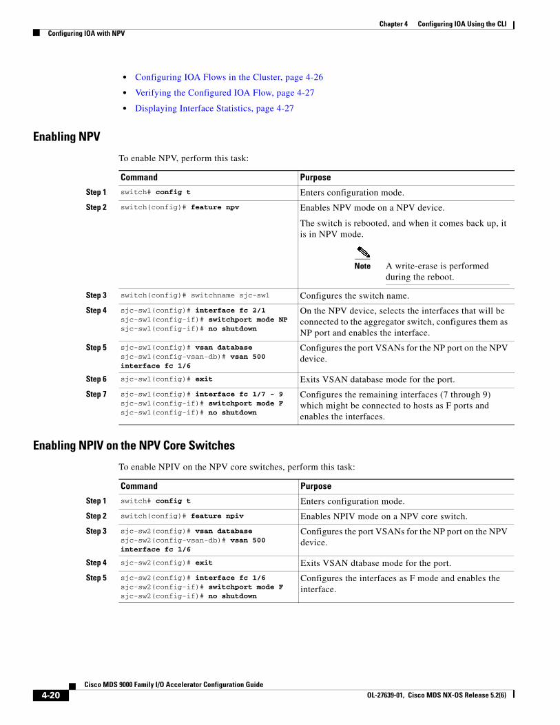
Chapter 4 Configuring IOA Using the CLI Configuring IOA with NPV
• Configuring IOA Flows in the Cluster, page 4-26
• Verifying the Configured IOA Flow, page 4-27
• Displaying Interface Statistics, page 4-27
Enabling NPV
To enable NPV, perform this task:
Command Purpose
Step 1 switch# config t Enters configuration mode.
Step 2 switch(config)# feature npv Enables NPV mode on a NPV device.
The switch is rebooted, and when it comes back up, it is in NPV mode.
Note A write-erase is performed during the reboot.
Step 3 switch(config)# switchname sjc-sw1 Configures the switch name.
Step 4 sjc-sw1(config)# interface fc 2/1sjc-sw1(config-if)# switchport mode NPsjc-sw1(config-if)# no shutdown
On the NPV device, selects the interfaces that will be connected to the aggregator switch, configures them as NP port and enables the interface.
Step 5 sjc-sw1(config)# vsan databasesjc-sw1(config-vsan-db)# vsan 500 interface fc 1/6
Configures the port VSANs for the NP port on the NPV device.
Step 6 sjc-sw1(config)# exit Exits VSAN database mode for the port.
Step 7 sjc-sw1(config)# interface fc 1/7 - 9sjc-sw1(config-if)# switchport mode Fsjc-sw1(config-if)# no shutdown
Configures the remaining interfaces (7 through 9) which might be connected to hosts as F ports and enables the interfaces.
Enabling NPIV on the NPV Core Switches
To enable NPIV on the NPV core switches, perform this task:
Command Purpose
Step 1 switch# config t Enters configuration mode.
Step 2 switch(config)# feature npiv Enables NPIV mode on a NPV core switch.
Step 3 sjc-sw2(config)# vsan databasesjc-sw2(config-vsan-db)# vsan 500 interface fc 1/6
Configures the port VSANs for the NP port on the NPV device.
Step 4 sjc-sw2(config)# exit Exits VSAN dtabase mode for the port.
Step 5 sjc-sw2(config)# interface fc 1/6sjc-sw2(config-if)# switchport mode Fsjc-sw2(config-if)# no shutdown
Configures the interfaces as F mode and enables the interface.
4-20Cisco MDS 9000 Family I/O Accelerator Configuration Guide
OL-27639-01, Cisco MDS NX-OS Release 5.2(6)
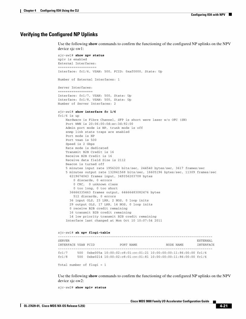
Chapter 4 Configuring IOA Using the CLIConfiguring IOA with NPV
Verifying the Configured NP Uplinks
Use the following show commands to confirm the functioning of the configured NP uplinks on the NPV device sjc-sw1:
sjc-sw1# show npv statusnpiv is enabledExternal Interfaces:====================Interface: fc1/6, VSAN: 500, FCID: 0xaf0000, State: Up
Number of External Interfaces: 1
Server Interfaces:==================Interface: fc1/7, VSAN: 500, State: UpInterface: fc1/8, VSAN: 500, State: UpNumber of Server Interfaces: 2
sjc-sw1# show interface fc 1/6fc1/6 is up Hardware is Fibre Channel, SFP is short wave laser w/o OFC (SN) Port WWN is 20:06:00:0d:ec:3d:92:00 Admin port mode is NP, trunk mode is off snmp link state traps are enabled Port mode is NP Port vsan is 500 Speed is 2 Gbps Rate mode is dedicated Transmit B2B Credit is 16 Receive B2B Credit is 16 Receive data field Size is 2112 Beacon is turned off 5 minutes input rate 1956320 bits/sec, 244540 bytes/sec, 3617 frames/sec 5 minutes output rate 132841568 bits/sec, 16605196 bytes/sec, 11309 frames/sec 6219674043 frames input, 349356203708 bytes 0 discards, 0 errors 0 CRC, 0 unknown class 0 too long, 0 too short 36666335463 frames output, 64666483082476 bytes 512 discards, 0 errors 36 input OLS, 23 LRR, 2 NOS, 0 loop inits 29 output OLS, 17 LRR, 14 NOS, 0 loop inits 0 receive B2B credit remaining 16 transmit B2B credit remaining 14 low priority transmit B2B credit remaining Interface last changed at Mon Oct 10 10:07:54 2011
sjc-sw1# sh npv flogi-table --------------------------------------------------------------------------------SERVER EXTERNALINTERFACE VSAN FCID PORT NAME NODE NAME INTERFACE--------------------------------------------------------------------------------fc1/7 500 0xbe005a 10:00:02:c8:01:cc:01:21 10:00:00:00:11:86:00:00 fc1/6fc1/8 500 0xbe0214 10:00:02:c8:01:cc:01:81 10:00:00:00:11:86:00:00 fc1/6
Total number of flogi = 1
Use the following show commands to confirm the functioning of the configured NP uplinks on the NPV device sjc-sw2:
sjc-sw2# show npiv status
4-21Cisco MDS 9000 Family I/O Accelerator Configuration Guide
OL-27639-01, Cisco MDS NX-OS Release 5.2(6)
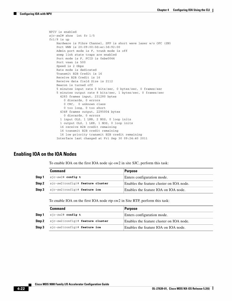
Chapter 4 Configuring IOA Using the CLI Configuring IOA with NPV
NPIV is enabledsjc-sw2# show int fc 1/5fc1/9 is up Hardware is Fibre Channel, SFP is short wave laser w/o OFC (SN) Port WWN is 20:09:00:0d:ec:3d:92:00 Admin port mode is F, trunk mode is off snmp link state traps are enabled Port mode is F, FCID is 0xbe0044 Port vsan is 500 Speed is 2 Gbps Rate mode is dedicated Transmit B2B Credit is 16 Receive B2B Credit is 16 Receive data field Size is 2112 Beacon is turned off 5 minutes input rate 0 bits/sec, 0 bytes/sec, 0 frames/sec 5 minutes output rate 8 bits/sec, 1 bytes/sec, 0 frames/sec 4283 frames input, 231280 bytes 0 discards, 0 errors 0 CRC, 0 unknown class 0 too long, 0 too short 4348 frames output, 2295004 bytes 0 discards, 0 errors 1 input OLS, 1 LRR, 2 NOS, 0 loop inits 1 output OLS, 1 LRR, 1 NOS, 0 loop inits 16 receive B2B credit remaining 16 transmit B2B credit remaining 16 low priority transmit B2B credit remaining Interface last changed at Fri Sep 30 09:24:40 2011
Enabling IOA on the IOA Nodes
To enable IOA on the first IOA node sjc-sw2 in site SJC, perform this task:
Command Purpose
Step 1 sjc-sw2# config t Enters configuration mode.
Step 2 sjc-sw2(config)# feature cluster Enables the feature cluster on IOA node.
Step 3 sjc-sw2(config)# feature ioa Enables the feature IOA on IOA node.
To enable IOA on the first IOA node rtp-sw2 in Site RTP, perform this task:
Command Purpose
Step 1 sjc-sw2# config t Enters configuration mode.
Step 2 sjc-sw2(config)# feature cluster Enables the feature cluster on IOA node.
Step 3 sjc-sw2(config)# feature ioa Enables the feature IOA on IOA node.
4-22Cisco MDS 9000 Family I/O Accelerator Configuration Guide
OL-27639-01, Cisco MDS NX-OS Release 5.2(6)
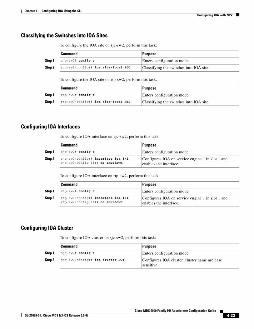
Chapter 4 Configuring IOA Using the CLIConfiguring IOA with NPV
Classifying the Switches into IOA Sites
To configure the IOA site on sjc-sw2, perform this task:
Command Purpose
Step 1 sjc-sw2# config t Enters configuration mode.
Step 2 sjc-sw2(config)# ioa site-local SJC Classifying the switches into IOA site.
To configure the IOA site on rtp-sw2, perform this task:
Command Purpose
Step 1 rtp-sw2# config t Enters configuration mode.
Step 2 rtp-sw2(config)# ioa site-local RTP Classifying the switches into IOA site.
Configuring IOA Interfaces
To configure IOA interface on sjc-sw2, perform this task:
Command Purpose
Step 1 sjc-sw2# config t Enters configuration mode.
Step 2 sjc-sw2(config)# interface ioa 1/1sjc-sw2(config-if)# no shutdown
Configures IOA on service engine 1 in slot 1 and enables the interface.
To configure IOA interface on rtp-sw2, perform this task:
Command Purpose
Step 1 rtp-sw2# config t Enters configuration mode.
Step 2 rtp-sw2(config)# interface ioa 1/1rtp-sw2(config-if)# no shutdown
Configures IOA on service engine 1 in slot 1 and enables the interface.
Configuring IOA Cluster
To configure IOA cluster on sjc-sw2, perform this task:
Command Purpose
Step 1 sjc-sw2# config t Enters configuration mode.
Step 2 sjc-sw2(config)# ioa cluster DC1 Configures IOA cluster. cluster name are case sensitive.
4-23Cisco MDS 9000 Family I/O Accelerator Configuration Guide
OL-27639-01, Cisco MDS NX-OS Release 5.2(6)
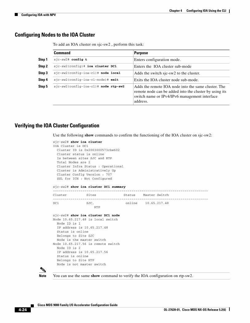
Chapter 4 Configuring IOA Using the CLI Configuring IOA with NPV
Configuring Nodes to the IOA Cluster
To add an IOA cluster on sjc-sw2 , perform this task:
Command Purpose
Step 1 sjc-sw2# config t Enters configuration mode.
Step 2 sjc-sw2(config)# ioa cluster DC1 Enters the IOA cluster sub-mode
Step 3 sjc-sw2(config-ioa-cl)# node local Adds the switch sjc-sw2 to the cluster.
Step 4 sjc-sw2(config-ioa-cl-node)# exit Exits the IOA cluster node sub-mode.
Step 5 sjc-sw2(config-ioa-cl)# node rtp-sw2 Adds the remote IOA node into the same cluster. The remote node can be added into the cluster by using its switch name or IPv4/IPv6 management interface address.
Verifying the IOA Cluster Configuration
Use the following show commands to confirm the functioning of the IOA cluster on sjc-sw2:
sjc-sw2# show ioa cluster IOA Cluster is DC1 Cluster ID is 0x2003000573cbe602 Cluster status is online Is between sites SJC and RTP Total Nodes are 2 Cluster Infra Status : Operational Cluster is Administratively Up Cluster Config Version : 707 SSL for ICN : Not Configured
sjc-sw2# show ioa cluster DC1 summary -------------------------------------------------------------------------------Cluster Sites Status Master Switch-------------------------------------------------------------------------------DC1 SJC, online 10.65.217.48 RTP
sjc-sw2# show ioa cluster DC1 node Node 10.65.217.48 is local switch Node ID is 1 IP address is 10.65.217.48 Status is online Belongs to Site SJC Node is the master switchNode 10.65.217.56 is remote switch Node ID is 2 IP address is 10.65.217.56 Status is online Belongs to Site RTP Node is not master switch
Note You can use the same show command to verify the IOA configuration on rtp-sw2.
4-24Cisco MDS 9000 Family I/O Accelerator Configuration Guide
OL-27639-01, Cisco MDS NX-OS Release 5.2(6)
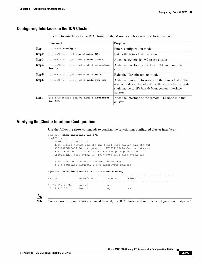
Chapter 4 Configuring IOA Using the CLIConfiguring IOA with NPV
Configuring Interfaces in the IOA Cluster
To add IOA interfaces to the IOA cluster on the Master switch sjc-sw2, perform this task:
Command Purpose
Step 1 sjc-sw2# config t Enters configuration mode.
Step 2 sjc-sw2(config)# ioa cluster DC1 Enters the IOA cluster sub-mode
Step 3 sjc-sw2(config-ioa-cl)# node local Adds the switch sjc-sw2 to the cluster
Step 4 sjc-sw2(config-ioa-cl-node)# interface ioa 1/1
Adds the interface of the local IOA node into the cluster.
Step 5 sjc-sw2(config-ioa-cl-node)# exit Exits the IOA cluster sub-mode.
Step 6 sjc-sw2(config-ioa-cl)# node rtp-sw2 Adds the remote IOA node into the same cluster. The remote node can be added into the cluster by using its switchname or IPv4/IPv6 Management interface address.
Step 7 sjc-sw2(config-ioa-cl-node)# interface ioa 1/1
Adds the interface of the remote IOA node into the cluster.
Verifying the Cluster Interface Configuration
Use the following show commands to confirm the functioning configured cluster interface:
sjc-sw2# show interface ioa 1/1ioa1/1 is up Member of cluster DC1 21368133123 device packets in, 6851375618 device packets out 31397026863066 device bytes in, 476831158620 device bytes out 914301804 peer packets in, 8706253930 peer packets out 56107433228 peer bytes in, 17877494274392 peer bytes out
0 i-t create request, 0 i-t create destroy 0 i-t activate request, 0 i-t deactivate request
sjc-sw2# show ioa cluster DC1 interface summary -------------------------------------------------------------------------------Switch Interface Status Flows-------------------------------------------------------------------------------10.65.217.48(L) ioa1/1 up -- 10.65.217.56 ioa1/1 up --
Note You can use the same show command to verify the IOA cluster and interface configuration on rtp-sw2.
4-25Cisco MDS 9000 Family I/O Accelerator Configuration Guide
OL-27639-01, Cisco MDS NX-OS Release 5.2(6)
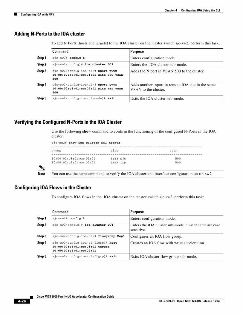
Chapter 4 Configuring IOA Using the CLI Configuring IOA with NPV
Adding N-Ports to the IOA cluster
To add N Ports (hosts and targets) to the IOA cluster on the master switch sjc-sw2, perform this task:
Command Purpose
Step 1 sjc-sw2# config t Enters configuration mode.
Step 2 sjc-sw2(config)# ioa cluster DC1 Enters the IOA cluster sub-mode.
Step 3 sjc-sw2(config-ioa-cl)# nport pwwn 10:00:02:c8:01:cc:01:01 site SJC vsan 500
Adds the N port in VSAN 500 to the cluster.
Step 4 sjc-sw2(config-ioa-cl)# nport pwwn 10:00:02:c8:01:cc:02:01 site RTP vsan 500
Adds another nport in remote IOA site in the same VSAN to the cluster.
Step 5 sjc-sw2(config-ioa-cl-node)# exit Exits the IOA cluster sub-mode.
Verifying the Configured N-Ports in the IOA Cluster
Use the following show command to confirm the functioning of the configured N-Ports in the IOA cluster:
sjc-sw2# show ioa cluster DC1 nports -------------------------------------------------------------------------------P-WWN Site Vsan-------------------------------------------------------------------------------10:00:02:c8:01:cc:01:01 SITE sjc 50010:00:02:c8:01:cc:02:01 SITE rtp 500
Note You can use the same command to verify the IOA cluster and interface configuration on rtp-sw2.
Configuring IOA Flows in the Cluster
To configure IOA flows in the IOA cluster on the master switch sjc-sw2, perform this task:
Command Purpose
Step 1 sjc-sw2# config t Enters configuration mode.
Step 2 sjc-sw2(config)# ioa cluster DC1 Enters the IOA cluster sub-mode. cluster name are case sensitive.
Step 3 sjc-sw2(config-ioa-cl)# flowgroup Dep1 Configures an IOA flow group.
Step 4 sjc-sw2(config-ioa-cl-flgrp)# host 10:00:02:c8:01:cc:01:01 target 10:00:02:c8:01:cc:02:01
Creates an IOA flow with write acceleration.
Step 5 sjc-sw2(config-ioa-cl-flgrp)# exit Exits IOA cluster flow group sub-mode.
4-26Cisco MDS 9000 Family I/O Accelerator Configuration Guide
OL-27639-01, Cisco MDS NX-OS Release 5.2(6)
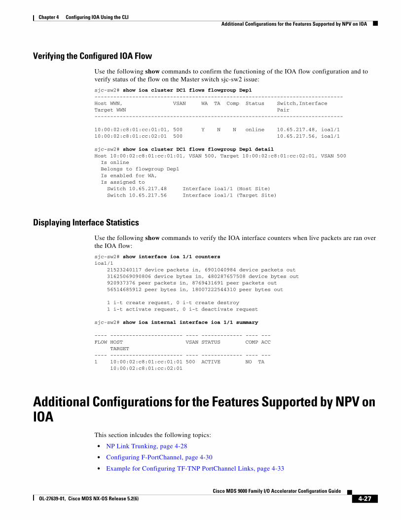
Chapter 4 Configuring IOA Using the CLIAdditional Configurations for the Features Supported by NPV on IOA
Verifying the Configured IOA Flow
Use the following show commands to confirm the functioning of the IOA flow configuration and to verify status of the flow on the Master switch sjc-sw2 issue:
sjc-sw2# show ioa cluster DC1 flows flowgroup Dep1-------------------------------------------------------------------------------Host WWN, VSAN WA TA Comp Status Switch,InterfaceTarget WWN Pair-------------------------------------------------------------------------------
10:00:02:c8:01:cc:01:01, 500 Y N N online 10.65.217.48, ioa1/110:00:02:c8:01:cc:02:01 500 10.65.217.56, ioa1/1
sjc-sw2# show ioa cluster DC1 flows flowgroup Dep1 detail Host 10:00:02:c8:01:cc:01:01, VSAN 500, Target 10:00:02:c8:01:cc:02:01, VSAN 500 Is online Belongs to flowgroup Dep1 Is enabled for WA, Is assigned to Switch 10.65.217.48 Interface ioa1/1 (Host Site) Switch 10.65.217.56 Interface ioa1/1 (Target Site)
Displaying Interface Statistics
Use the following show commands to verify the IOA interface counters when live packets are ran over the IOA flow:
sjc-sw2# show interface ioa 1/1 counters ioa1/1 21523240117 device packets in, 6901040984 device packets out 31625069090806 device bytes in, 480287657508 device bytes out 920937376 peer packets in, 8769431691 peer packets out 56514685912 peer bytes in, 18007222544310 peer bytes out
1 i-t create request, 0 i-t create destroy 1 i-t activate request, 0 i-t deactivate request
sjc-sw2# show ioa internal interface ioa 1/1 summary
---- ----------------------- ---- ------------- ---- ---FLOW HOST VSAN STATUS COMP ACC TARGET ---- ----------------------- ---- ------------- ---- ---1 10:00:02:c8:01:cc:01:01 500 ACTIVE NO TA 10:00:02:c8:01:cc:02:01
Additional Configurations for the Features Supported by NPV on IOA
This section inlcudes the following topics:
• NP Link Trunking, page 4-28
• Configuring F-PortChannel, page 4-30
• Example for Configuring TF-TNP PortChannel Links, page 4-33
4-27Cisco MDS 9000 Family I/O Accelerator Configuration Guide
OL-27639-01, Cisco MDS NX-OS Release 5.2(6)
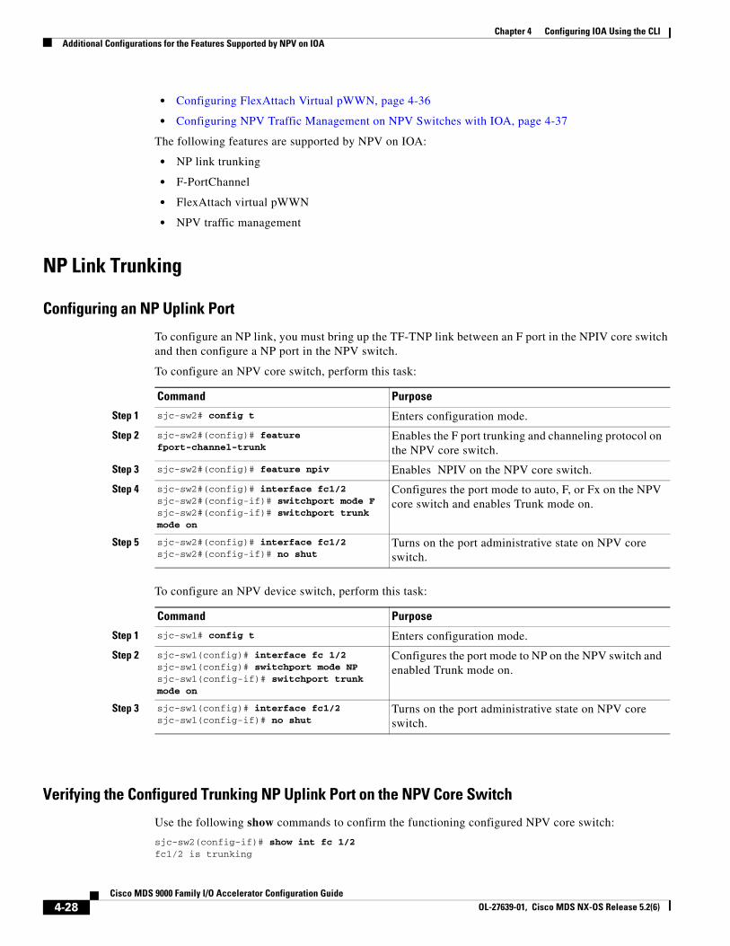
Chapter 4 Configuring IOA Using the CLI Additional Configurations for the Features Supported by NPV on IOA
• Configuring FlexAttach Virtual pWWN, page 4-36
• Configuring NPV Traffic Management on NPV Switches with IOA, page 4-37
The following features are supported by NPV on IOA:
• NP link trunking
• F-PortChannel
• FlexAttach virtual pWWN
• NPV traffic management
NP Link Trunking
Configuring an NP Uplink Port
To configure an NP link, you must bring up the TF-TNP link between an F port in the NPIV core switch and then configure a NP port in the NPV switch.
To configure an NPV core switch, perform this task:
Command Purpose
Step 1 sjc-sw2# config t Enters configuration mode.
Step 2 sjc-sw2#(config)# feature fport-channel-trunk
Enables the F port trunking and channeling protocol on the NPV core switch.
Step 3 sjc-sw2#(config)# feature npiv Enables NPIV on the NPV core switch.
Step 4 sjc-sw2#(config)# interface fc1/2sjc-sw2#(config-if)# switchport mode Fsjc-sw2#(config-if)# switchport trunk mode on
Configures the port mode to auto, F, or Fx on the NPV core switch and enables Trunk mode on.
Step 5 sjc-sw2#(config)# interface fc1/2sjc-sw2#(config-if)# no shut
Turns on the port administrative state on NPV core switch.
To configure an NPV device switch, perform this task:
Command Purpose
Step 1 sjc-sw1# config t Enters configuration mode.
Step 2 sjc-sw1(config)# interface fc 1/2sjc-sw1(config)# switchport mode NPsjc-sw1(config-if)# switchport trunk mode on
Configures the port mode to NP on the NPV switch and enabled Trunk mode on.
Step 3 sjc-sw1(config)# interface fc1/2sjc-sw1(config-if)# no shut
Turns on the port administrative state on NPV core switch.
Verifying the Configured Trunking NP Uplink Port on the NPV Core Switch
Use the following show commands to confirm the functioning configured NPV core switch:
sjc-sw2(config-if)# show int fc 1/2fc1/2 is trunking
4-28Cisco MDS 9000 Family I/O Accelerator Configuration Guide
OL-27639-01, Cisco MDS NX-OS Release 5.2(6)
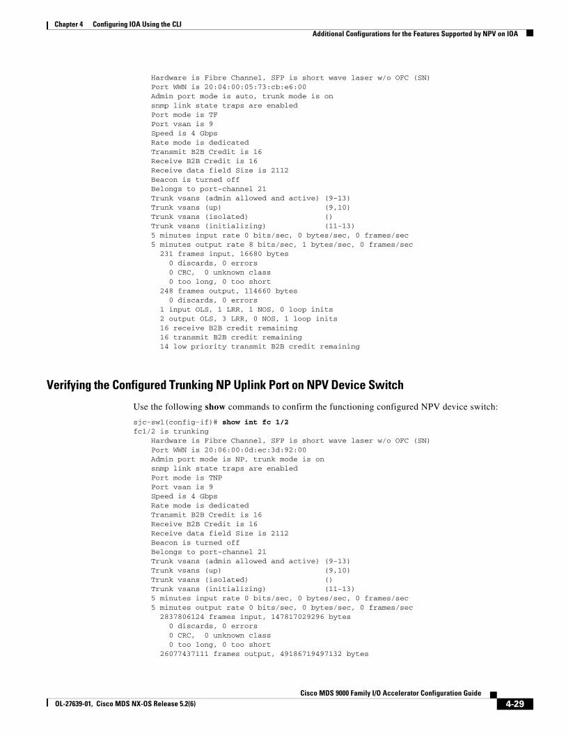
Chapter 4 Configuring IOA Using the CLIAdditional Configurations for the Features Supported by NPV on IOA
Hardware is Fibre Channel, SFP is short wave laser w/o OFC (SN) Port WWN is 20:04:00:05:73:cb:e6:00 Admin port mode is auto, trunk mode is on snmp link state traps are enabled Port mode is TF Port vsan is 9 Speed is 4 Gbps Rate mode is dedicated Transmit B2B Credit is 16 Receive B2B Credit is 16 Receive data field Size is 2112 Beacon is turned off Belongs to port-channel 21 Trunk vsans (admin allowed and active) (9-13) Trunk vsans (up) (9,10) Trunk vsans (isolated) () Trunk vsans (initializing) (11-13) 5 minutes input rate 0 bits/sec, 0 bytes/sec, 0 frames/sec 5 minutes output rate 8 bits/sec, 1 bytes/sec, 0 frames/sec 231 frames input, 16680 bytes 0 discards, 0 errors 0 CRC, 0 unknown class 0 too long, 0 too short 248 frames output, 114660 bytes 0 discards, 0 errors 1 input OLS, 1 LRR, 1 NOS, 0 loop inits 2 output OLS, 3 LRR, 0 NOS, 1 loop inits 16 receive B2B credit remaining 16 transmit B2B credit remaining 14 low priority transmit B2B credit remaining
Verifying the Configured Trunking NP Uplink Port on NPV Device Switch
Use the following show commands to confirm the functioning configured NPV device switch:
sjc-sw1(config-if)# show int fc 1/2fc1/2 is trunking Hardware is Fibre Channel, SFP is short wave laser w/o OFC (SN) Port WWN is 20:06:00:0d:ec:3d:92:00 Admin port mode is NP, trunk mode is on snmp link state traps are enabled Port mode is TNP Port vsan is 9 Speed is 4 Gbps Rate mode is dedicated Transmit B2B Credit is 16 Receive B2B Credit is 16 Receive data field Size is 2112 Beacon is turned off Belongs to port-channel 21 Trunk vsans (admin allowed and active) (9-13) Trunk vsans (up) (9,10) Trunk vsans (isolated) () Trunk vsans (initializing) (11-13) 5 minutes input rate 0 bits/sec, 0 bytes/sec, 0 frames/sec 5 minutes output rate 0 bits/sec, 0 bytes/sec, 0 frames/sec 2837806124 frames input, 147817029296 bytes 0 discards, 0 errors 0 CRC, 0 unknown class 0 too long, 0 too short 26077437111 frames output, 49186719497132 bytes
4-29Cisco MDS 9000 Family I/O Accelerator Configuration Guide
OL-27639-01, Cisco MDS NX-OS Release 5.2(6)
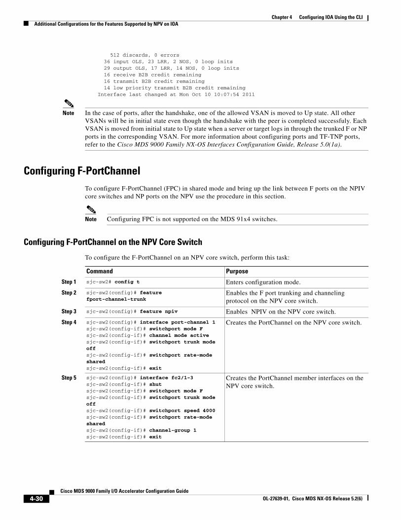
Chapter 4 Configuring IOA Using the CLI Additional Configurations for the Features Supported by NPV on IOA
512 discards, 0 errors 36 input OLS, 23 LRR, 2 NOS, 0 loop inits 29 output OLS, 17 LRR, 14 NOS, 0 loop inits 16 receive B2B credit remaining 16 transmit B2B credit remaining 14 low priority transmit B2B credit remaining Interface last changed at Mon Oct 10 10:07:54 2011
Note In the case of ports, after the handshake, one of the allowed VSAN is moved to Up state. All other VSANs will be in initial state even though the handshake with the peer is completed successfuly. Each VSAN is moved from initial state to Up state when a server or target logs in through the trunked F or NP ports in the corresponding VSAN. For more information about configuring ports and TF-TNP ports, refer to the Cisco MDS 9000 Family NX-OS Interfaces Configuration Guide, Release 5.0(1a).
Configuring F-PortChannelTo configure F-PortChannel (FPC) in shared mode and bring up the link between F ports on the NPIV core switches and NP ports on the NPV use the procedure in this section.
Note Configuring FPC is not supported on the MDS 91x4 switches.
Configuring F-PortChannel on the NPV Core Switch
To configure the F-PortChannel on an NPV core switch, perform this task:
Command Purpose
Step 1 sjc-sw2# config t Enters configuration mode.
Step 2 sjc-sw2(config)# feature fport-channel-trunk
Enables the F port trunking and channeling protocol on the NPV core switch.
Step 3 sjc-sw2(config)# feature npiv Enables NPIV on the NPV core switch.
Step 4 sjc-sw2(config)# interface port-channel 1sjc-sw2(config-if)# switchport mode Fsjc-sw2(config-if)# channel mode activesjc-sw2(config-if)# switchport trunk mode offsjc-sw2(config-if)# switchport rate-mode sharedsjc-sw2(config-if)# exit
Creates the PortChannel on the NPV core switch.
Step 5 sjc-sw2(config)# interface fc2/1-3sjc-sw2(config-if)# shutsjc-sw2(config-if)# switchport mode Fsjc-sw2(config-if)# switchport trunk mode offsjc-sw2(config-if)# switchport speed 4000sjc-sw2(config-if)# switchport rate-mode sharedsjc-sw2(config-if)# channel-group 1sjc-sw2(config-if)# exit
Creates the PortChannel member interfaces on the NPV core switch.
4-30Cisco MDS 9000 Family I/O Accelerator Configuration Guide
OL-27639-01, Cisco MDS NX-OS Release 5.2(6)
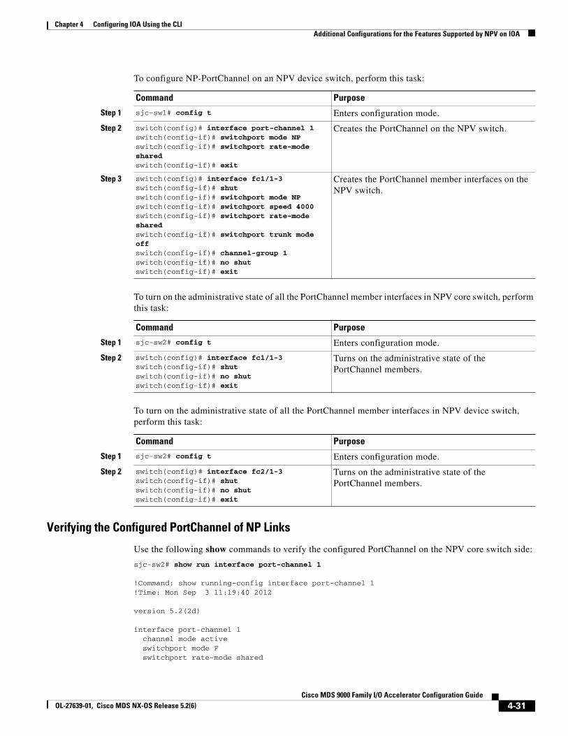
Chapter 4 Configuring IOA Using the CLIAdditional Configurations for the Features Supported by NPV on IOA
To configure NP-PortChannel on an NPV device switch, perform this task:
Command Purpose
Step 1 sjc-sw1# config t Enters configuration mode.
Step 2 switch(config)# interface port-channel 1switch(config-if)# switchport mode NPswitch(config-if)# switchport rate-mode sharedswitch(config-if)# exit
Creates the PortChannel on the NPV switch.
Step 3 switch(config)# interface fc1/1-3switch(config-if)# shutswitch(config-if)# switchport mode NPswitch(config-if)# switchport speed 4000switch(config-if)# switchport rate-mode sharedswitch(config-if)# switchport trunk mode offswitch(config-if)# channel-group 1switch(config-if)# no shutswitch(config-if)# exit
Creates the PortChannel member interfaces on the NPV switch.
To turn on the administrative state of all the PortChannel member interfaces in NPV core switch, perform this task:
Command Purpose
Step 1 sjc-sw2# config t Enters configuration mode.
Step 2 switch(config)# interface fc1/1-3switch(config-if)# shutswitch(config-if)# no shutswitch(config-if)# exit
Turns on the administrative state of the PortChannel members.
To turn on the administrative state of all the PortChannel member interfaces in NPV device switch, perform this task:
Command Purpose
Step 1 sjc-sw2# config t Enters configuration mode.
Step 2 switch(config)# interface fc2/1-3switch(config-if)# shutswitch(config-if)# no shutswitch(config-if)# exit
Turns on the administrative state of the PortChannel members.
Verifying the Configured PortChannel of NP Links
Use the following show commands to verify the configured PortChannel on the NPV core switch side:
sjc-sw2# show run interface port-channel 1
!Command: show running-config interface port-channel 1!Time: Mon Sep 3 11:19:40 2012
version 5.2(2d)
interface port-channel 1 channel mode active switchport mode F switchport rate-mode shared
4-31Cisco MDS 9000 Family I/O Accelerator Configuration Guide
OL-27639-01, Cisco MDS NX-OS Release 5.2(6)
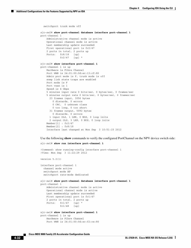
Chapter 4 Configuring IOA Using the CLI Additional Configurations for the Features Supported by NPV on IOA
switchport trunk mode off sjc-sw2# show port-channel database interface port-channel 1port-channel 1 Administrative channel mode is active Operational channel mode is active Last membership update succeeded First operational port is fc2/47 2 ports in total, 2 ports up Ports: fc8/18 [up] fc2/47 [up] *
sjc-sw2# show interface port-channel 1port-channel 1 is up Hardware is Fibre Channel Port WWN is 24:01:00:0d:ec:13:cf:80 Admin port mode is F, trunk mode is off snmp link state traps are enabled Port mode is F Port vsan is 1 Speed is 4 Gbps 5 minutes input rate 0 bits/sec, 0 bytes/sec, 0 frames/sec 5 minutes output rate 0 bits/sec, 0 bytes/sec, 0 frames/sec 23 frames input, 3056 bytes 0 discards, 0 errors 0 CRC, 0 unknown class 0 too long, 0 too short 31 frames output, 5092 bytes 0 discards, 0 errors 1 input OLS, 1 LRR, 0 NOS, 0 loop inits 2 output OLS, 3 LRR, 0 NOS, 0 loop inits Member[1] : fc2/47 Member[2] : fc8/18 Interface last changed at Mon Sep 3 10:51:15 2012
Use the following show commands to verify the configured PortChannel on the NPV device switch side:
sjc-sw1# show run interface port-channel 1
!Command: show running-config interface port-channel 1!Time: Mon Sep 3 11:22:29 2012
version 5.2(1)
interface port-channel 1 channel mode active switchport mode NP switchport rate-mode dedicated
sjc-sw1# show port-channel database interface port-channel 1port-channel 1 Administrative channel mode is active Operational channel mode is active Last membership update succeeded First operational port is fc1/47 2 ports in total, 2 ports up Ports: fc1/47 [up] * fc1/48 [up]
sjc-sw1# show interface port-channel 1port-channel 1 is up Hardware is Fibre Channel Port WWN is 24:01:00:0d:ec:f2:ce:80
4-32Cisco MDS 9000 Family I/O Accelerator Configuration Guide
OL-27639-01, Cisco MDS NX-OS Release 5.2(6)
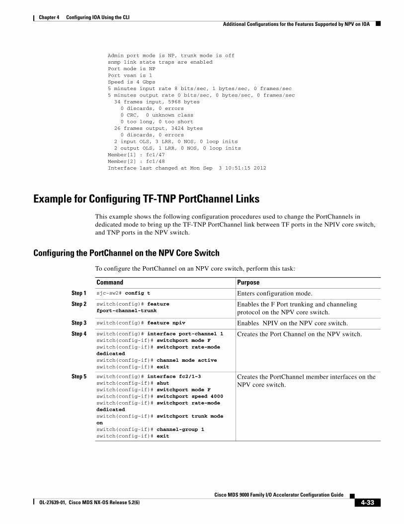
Chapter 4 Configuring IOA Using the CLIAdditional Configurations for the Features Supported by NPV on IOA
Admin port mode is NP, trunk mode is off snmp link state traps are enabled Port mode is NP Port vsan is 1 Speed is 4 Gbps 5 minutes input rate 8 bits/sec, 1 bytes/sec, 0 frames/sec 5 minutes output rate 0 bits/sec, 0 bytes/sec, 0 frames/sec 34 frames input, 5968 bytes 0 discards, 0 errors 0 CRC, 0 unknown class 0 too long, 0 too short 26 frames output, 3424 bytes 0 discards, 0 errors 2 input OLS, 3 LRR, 0 NOS, 0 loop inits 2 output OLS, 1 LRR, 0 NOS, 0 loop inits Member[1] : fc1/47 Member[2] : fc1/48 Interface last changed at Mon Sep 3 10:51:15 2012
Example for Configuring TF-TNP PortChannel LinksThis example shows the following configuration procedures used to change the PortChannels in dedicated mode to bring up the TF-TNP PortChannel link between TF ports in the NPIV core switch, and TNP ports in the NPV switch.
Configuring the PortChannel on the NPV Core Switch
To configure the PortChannel on an NPV core switch, perform this task:
Command Purpose
Step 1 sjc-sw2# config t Enters configuration mode.
Step 2 switch(config)# feature fport-channel-trunk
Enables the F Port trunking and channeling protocol on the NPV core switch.
Step 3 switch(config)# feature npiv Enables NPIV on the NPV core switch.
Step 4 switch(config)# interface port-channel 1switch(config-if)# switchport mode Fswitch(config-if)# switchport rate-mode dedicatedswitch(config-if)# channel mode activeswitch(config-if)# exit
Creates the Port Channel on the NPV switch.
Step 5 switch(config)# interface fc2/1-3switch(config-if)# shutswitch(config-if)# switchport mode Fswitch(config-if)# switchport speed 4000switch(config-if)# switchport rate-mode dedicatedswitch(config-if)# switchport trunk mode onswitch(config-if)# channel-group 1switch(config-if)# exit
Creates the PortChannel member interfaces on the NPV core switch.
4-33Cisco MDS 9000 Family I/O Accelerator Configuration Guide
OL-27639-01, Cisco MDS NX-OS Release 5.2(6)
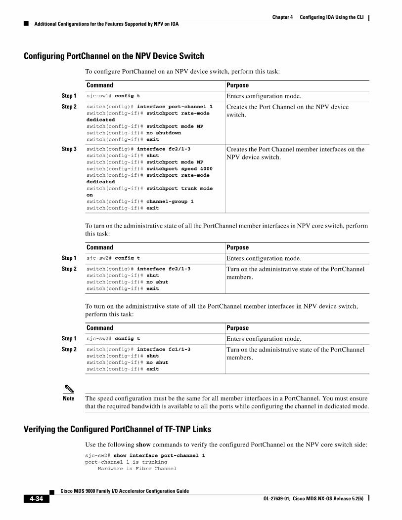
Chapter 4 Configuring IOA Using the CLI Additional Configurations for the Features Supported by NPV on IOA
Configuring PortChannel on the NPV Device Switch
To configure PortChannel on an NPV device switch, perform this task:
Command Purpose
Step 1 sjc-sw1# config t Enters configuration mode.
Step 2 switch(config)# interface port-channel 1switch(config-if)# switchport rate-mode dedicatedswitch(config-if)# switchport mode NPswitch(config-if)# no shutdownswitch(config-if)# exit
Creates the Port Channel on the NPV device switch.
Step 3 switch(config)# interface fc2/1-3switch(config-if)# shutswitch(config-if)# switchport mode NPswitch(config-if)# switchport speed 4000switch(config-if)# switchport rate-mode dedicatedswitch(config-if)# switchport trunk mode onswitch(config-if)# channel-group 1switch(config-if)# exit
Creates the Port Channel member interfaces on the NPV device switch.
To turn on the administrative state of all the PortChannel member interfaces in NPV core switch, perform this task:
Command Purpose
Step 1 sjc-sw2# config t Enters configuration mode.
Step 2 switch(config)# interface fc2/1-3switch(config-if)# shutswitch(config-if)# no shutswitch(config-if)# exit
Turn on the administrative state of the PortChannel members.
To turn on the administrative state of all the PortChannel member interfaces in NPV device switch, perform this task:
Command Purpose
Step 1 sjc-sw2# config t Enters configuration mode.
Step 2 switch(config)# interface fc1/1-3switch(config-if)# shutswitch(config-if)# no shutswitch(config-if)# exit
Turn on the administrative state of the PortChannel members.
Note The speed configuration must be the same for all member interfaces in a PortChannel. You must ensure that the required bandwidth is available to all the ports while configuring the channel in dedicated mode.
Verifying the Configured PortChannel of TF-TNP Links
Use the following show commands to verify the configured PortChannel on the NPV core switch side:
sjc-sw2# show interface port-channel 1port-channel 1 is trunking Hardware is Fibre Channel
4-34Cisco MDS 9000 Family I/O Accelerator Configuration Guide
OL-27639-01, Cisco MDS NX-OS Release 5.2(6)
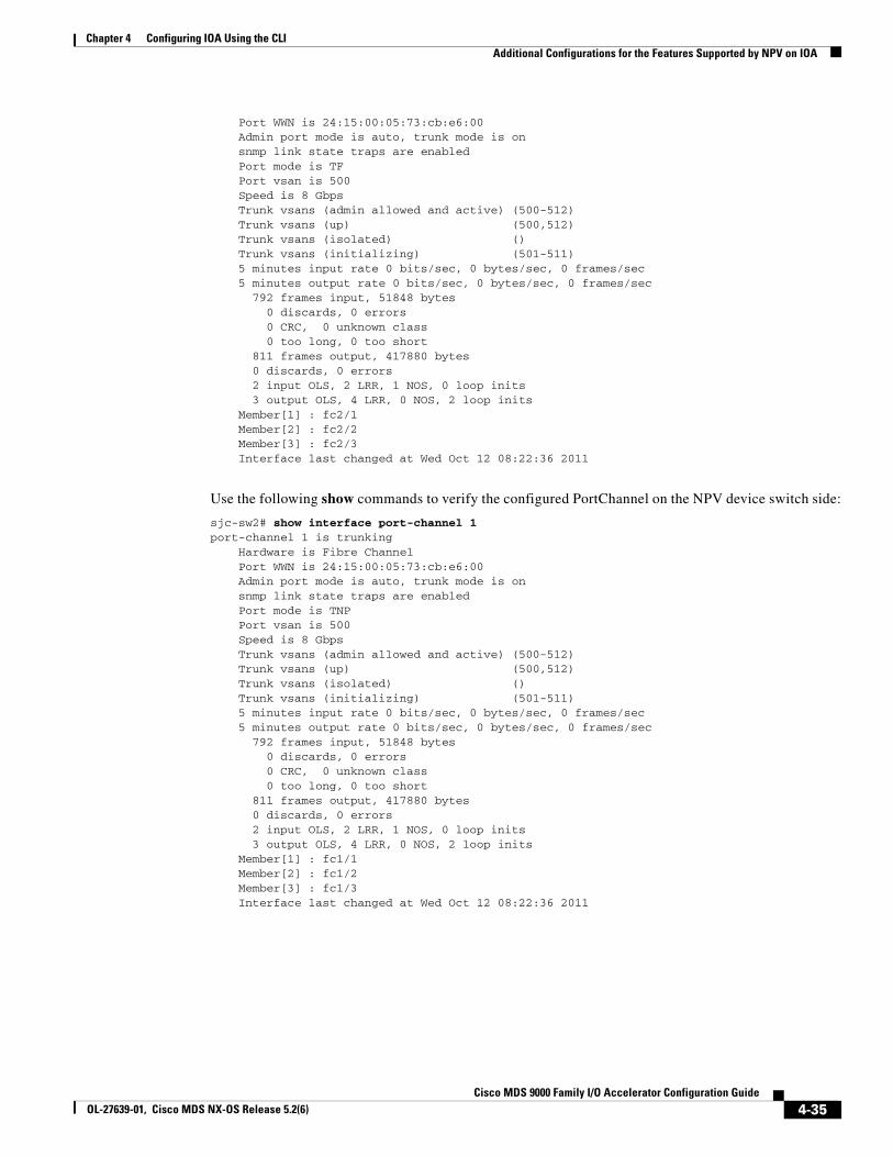
Chapter 4 Configuring IOA Using the CLIAdditional Configurations for the Features Supported by NPV on IOA
Port WWN is 24:15:00:05:73:cb:e6:00 Admin port mode is auto, trunk mode is on snmp link state traps are enabled Port mode is TF Port vsan is 500 Speed is 8 Gbps Trunk vsans (admin allowed and active) (500-512) Trunk vsans (up) (500,512) Trunk vsans (isolated) () Trunk vsans (initializing) (501-511) 5 minutes input rate 0 bits/sec, 0 bytes/sec, 0 frames/sec 5 minutes output rate 0 bits/sec, 0 bytes/sec, 0 frames/sec 792 frames input, 51848 bytes 0 discards, 0 errors 0 CRC, 0 unknown class 0 too long, 0 too short 811 frames output, 417880 bytes 0 discards, 0 errors 2 input OLS, 2 LRR, 1 NOS, 0 loop inits 3 output OLS, 4 LRR, 0 NOS, 2 loop inits Member[1] : fc2/1 Member[2] : fc2/2 Member[3] : fc2/3 Interface last changed at Wed Oct 12 08:22:36 2011
Use the following show commands to verify the configured PortChannel on the NPV device switch side:
sjc-sw2# show interface port-channel 1port-channel 1 is trunking Hardware is Fibre Channel Port WWN is 24:15:00:05:73:cb:e6:00 Admin port mode is auto, trunk mode is on snmp link state traps are enabled Port mode is TNP Port vsan is 500 Speed is 8 Gbps Trunk vsans (admin allowed and active) (500-512) Trunk vsans (up) (500,512) Trunk vsans (isolated) () Trunk vsans (initializing) (501-511) 5 minutes input rate 0 bits/sec, 0 bytes/sec, 0 frames/sec 5 minutes output rate 0 bits/sec, 0 bytes/sec, 0 frames/sec 792 frames input, 51848 bytes 0 discards, 0 errors 0 CRC, 0 unknown class 0 too long, 0 too short 811 frames output, 417880 bytes 0 discards, 0 errors 2 input OLS, 2 LRR, 1 NOS, 0 loop inits 3 output OLS, 4 LRR, 0 NOS, 2 loop inits Member[1] : fc1/1 Member[2] : fc1/2 Member[3] : fc1/3 Interface last changed at Wed Oct 12 08:22:36 2011
4-35Cisco MDS 9000 Family I/O Accelerator Configuration Guide
OL-27639-01, Cisco MDS NX-OS Release 5.2(6)
Chapter 4 Configuring IOA Using the CLI Additional Configurations for the Features Supported by NPV on IOA
Configuring FlexAttach Virtual pWWNThe FlexAttach virtual pWWN feature facilitates server and configuration management. In a SAN environment, the server installation or replacement requires interaction and coordination among the SAN and server administrators. It is important that the SAN configuration does not change when a new server is installed, or when an existing server is replaced.
FlexAttach virtual pWWN minimizes the interaction between the server administrator and the SAN administrator by abstracting the real pWWN using virtual pWWNs. When FlexAttach virtual pWWN is enabled on an interface, a virtual pWWN is assigned to the server interface. The real pWWN is replaced by a virtual pWWN, which is used for a SAN configuration such as zoning.
With pWWNs configured on NPV switch in various forms as described in the next section, IOA works seamlessly with PwwNs. The pWWNs feature is enabled automatically, manually, or by mapping pWWN to virtual pWWN.
Automatically Enabling FlexAttach Virtual pWWN
The virtual pWWN is enabled automatically on all of the NPV switches or per port on the NPV device. When enabled automatically, a virtual WWN is generated from the device switch WWN. This WWN is used as the virtual pWWN. Virtual pWWNs are generated using the local switch WWNs.
Note The port must be in a shut state when the virtual pWWN is enabled.
To enable virtual pWWN automatically, perform this task:
Command Purpose
Step 1 sjc-sw2# config t Enters configuration mode.
Step 2 swtich(config)# flex-attach virtual-pwwn auto [interface interface-list]
Enables FlexAttach virtual pWWN automatically for the interfaces.
Step 3 switch(config)# flex-attach commit Commits the configuration.
Manually Enabling FlexAttach Virtual pWWN
You can manually assign a WWN to the interface, without generating it through the switch. Several checks are done by the NPV core to ensure the uniqueness of virtual pWWNs in the switch. When duplicate virtual pWWNs are configured, the subsequent logins are rejected by the NPV core switch.
Note • Some ports may be in automode, some in manual mode, and the virtual pWWNs need not be assigned.
• The port must be in a shut state when a virtual pWWN is enabled.
• The interface mentioned in the interface value must be in a shut state.
To enable virtual pWWN manually, perform this task:
Command Purpose
Step 1 switch# config t Enters configuration mode.
4-36Cisco MDS 9000 Family I/O Accelerator Configuration Guide
OL-27639-01, Cisco MDS NX-OS Release 5.2(6)
Chapter 4 Configuring IOA Using the CLIAdditional Configurations for the Features Supported by NPV on IOA
Verifying the Configured FlexAttach Virtual pWWN
Use the following show commands to verify the type and value of virtual pWWNs are correct:
sjc-sw1# show flex-attach virtual-wwnVIRTUAL PORT WWNS ASSIGNED TO INTERFACES----------------------------------------------------------------------VSAN INTERFACE VIRTUAL-PWWN AUTO LAST-CHANGE----------------------------------------------------------------------1 fc1/1 00:00:00:00:00:00:00:001 fc1/2 22:73:00:05:30:01:6e:1e TRUE Thu Jan 31 01:58:52 20081 fc1/3 22:5e:00:05:30:01:6e:1e TRUE Thu Jan 31 01:58:52 20081 fc1/4 22:5f:00:05:30:01:6e:1e TRUE Thu Jan 31 01:58:52 20081 fc1/5 22:74:00:05:30:01:6e:1e TRUE Thu Jan 31 01:26:24 20081 fc1/6 22:60:00:05:30:01:6e:1e TRUE Thu Jan 31 01:58:52 20081 fc1/7 22:61:00:05:30:01:6e:1e TRUE Thu Jan 31 01:58:52 20081 fc1/8 22:62:00:05:30:01:6e:1e TRUE Thu Jan 31 01:58:52 20081 fc1/9 22:63:00:05:30:01:6e:1e TRUE Thu Jan 31 01:58:52 20081 fc1/10 22:64:00:05:30:01:6e:1e TRUE Thu Jan 31 01:58:52 20081 fc1/11 22:65:00:05:30:01:6e:1e TRUE Thu Jan 31 01:58:52 20081 fc1/12 22:66:00:05:30:01:6e:1e TRUE Thu Jan 31 01:58:52 2008
Verifying the Configured FlexAttach Virtual pWWN
Use the following show commands to verify that the end device is logged with the correct virtual WWNs:
switch# show fcns databaseVSAN 1:--------------------------------------------------------------------------FCID TYPE PWWN (VENDOR) FC4-TYPE:FEATURE--------------------------------------------------------------------------0x010000 N 20:01:00:0d:ec:2f:c1:40 (Cisco) npv0x010001 N 20:02:00:0d:ec:2f:c1:40 (Cisco) npv0x010200 N 21:00:00:e0:8b:83:01:a1 (Qlogic) scsi-fcp:init0x010300 N 21:01:00:e0:8b:32:1a:8b (Qlogic) scsi-fcp:initTotal number of entries = 4
Configuring NPV Traffic Management on NPV Switches with IOAConfiguring NPV traffic management involves configuring a list of external interfaces to the servers, and enabling or disabling disruptive load balancing. The NPV traffic management feature is enabled after configuring NPV.
Step 2 swtich(config)# flex-attach virtual-pwwn vpwwn interface interface
Enables FlexAttach virtual pWWN manually for the interfaces.
Step 3 switch(config)# flex-attach commit Commits the configuration.
Command Purpose
4-37Cisco MDS 9000 Family I/O Accelerator Configuration Guide
OL-27639-01, Cisco MDS NX-OS Release 5.2(6)
Chapter 4 Configuring IOA Using the CLI Additional Configurations for the Features Supported by NPV on IOA
Configuring a List of External Interfaces per Server Interface
A list of external interfaces is linked to the server interfaces when the server interface is down, or if the specified external interface list includes the external interface already in use.
To configure the list of external interfaces per server interface, perform this task:
Command Purpose
Step 1 sjc-sw2# config t Enters configuration mode.
Step 2 switch(config)# npv traffic-map server-interface fc 1/1-3external-interface fc 1/8-10
Allows you to configure a list of external FC interfaces to a range of server interface.
Step 3 switch(config)# npv traffic-map server-interface fc1/1-3 external-interface port-channel 10-12
Allows you to configure a list of external PortChannel interfaces per server interface.
Step 4 switch(config)# no npv traffic-map server-interface fc 1/1-3 external-interface fc 1/8-10
Disables the NPV traffic management feature on the NPV device switch.
Note You must map the non-PortChannel interfaces and PortChannel interfaces to the server interfaces, in two steps.
Enabling or Disabling the Global Policy for Disruptive Load Balancing
Disruptive load balancing allows you to review the load on all the external interfaces and balance the load disruptively. Disruptive load balancing is done by moving the servers using heavily loaded external interfaces, to the external interfaces running with fewer loads.
To enable or disable the global policy for disruptive load balancing, perform this task:
Command Purpose
Step 1 sjc-sw1# config t Enters configuration mode.
Step 2 switch(config)# npv auto-load-balance disruptive
Enables disruptive load balancing on the NPV device.
Step 3 switch(config)# no npv auto-load-balance disruptive
Disables disruptive load balancing on the NPV device.
Verifying the NPV Traffic Management on an NPV Switch
Use the following show command to display the NPV traffic map on an NPV switch:
switch# show npv traffic-mapNPV Traffic Map Information:----------------------------------------Server-If External-If(s)----------------------------------------fc1/3 fc1/10,fc1/11fc1/5 fc1/1,fc1/2----------------------------------------
Use the following show command to display the NPV internal traffic details on an NPV switch:
switch# show npv internal info traffic-mapNPV Traffic Map Information:
4-38Cisco MDS 9000 Family I/O Accelerator Configuration Guide
OL-27639-01, Cisco MDS NX-OS Release 5.2(6)
Chapter 4 Configuring IOA Using the CLIAdditional Configurations
----------------------------------------Server-If External-If(s)----------------------------------------fc1/3 fc1/10,fc1/11fc1/5 fc1/1,fc1/2----------------------------------------
Example for Implementing IOA with NPV
In this implementation example, an NPIV-capable server is the host directly connected to the NPV core (NPIV-enabled) switch which also acts as an IOA node. The host sends data to the target over IOA flows.
To enable NPIV on NPV core switch, perform this task:
Command Purpose
Step 1 sjc-sw2# config t Enters configuration mode.
Step 2 sjc-sw1(config)# feature npiv Enables NPIV mode on a NPV core switch.
To enable IOA on all the IOA nodes and to bring up the IOA flows, perform this task:
Command Purpose
Step 1 sjc-sw2# config t Enters configuration mode.
Step 2 sjc-sw1(config)# feature npiv Enables NPIV mode on a NPV nodes switches.
Verifying the IOA Configuration
Use the following show command to verify the IOA configuration:
sjc-sw1# show npiv status NPIV is enabled
Additional ConfigurationsThis section inlcudes the following topics:
• Shutting Down a Cluster, page 4-40
• Load Balancing the Flows, page 4-40
• Setting the Tunable Parameters, page 4-40
• Changing the Node Description and IP Address of an IOA Cluster, page 4-41
4-39Cisco MDS 9000 Family I/O Accelerator Configuration Guide
OL-27639-01, Cisco MDS NX-OS Release 5.2(6)
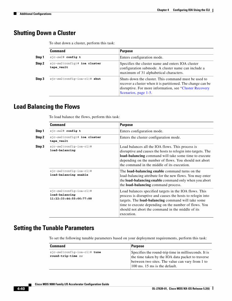
Chapter 4 Configuring IOA Using the CLI Additional Configurations
Shutting Down a ClusterTo shut down a cluster, perform this task:
Command Purpose
Step 1 sjc-sw2# config t Enters configuration mode.
Step 2 sjc-sw2(config)# ioa cluster tape_vault
Specifies the cluster name and enters IOA cluster configuration submode. A cluster name can include a maximum of 31 alphabetical characters.
Step 3 sjc-sw2(config-ioa-cl)# shut Shuts down the cluster. This command must be used to recover a cluster when it is partitioned. The change can be disruptive. For more information, see “Cluster Recovery Scenarios, page 1-5.
Load Balancing the FlowsTo load balance the flows, perform this task:
Command Purpose
Step 1 sjc-sw2# config t Enters configuration mode.
Step 2 sjc-sw2(config)# ioa cluster tape_vault
Enters the cluster configuration mode.
Step 3 sjc-sw2(config-ioa-cl)# load-balancing
Load balances all the IOA flows. This process is disruptive and causes the hosts to relogin into targets. The load-balancing command will take some time to execute depending on the number of flows. You should not abort the command in the middle of its execution.
sjc-sw2(config-ioa-cl)# load-balancing enable
The load-balancing enable command turns on the load-balancing attribute for the new flows. You may enter the load-balancing enable command only when you abort the load-balancing command process.
sjc-sw2(config-ioa-cl)# load-balancing 11:22:33:44:55:66:77:88
Load balances specified targets in the IOA flows. This process is disruptive and causes the hosts to relogin into targets. The load-balancing command will take some time to execute depending on the number of flows. You should not abort the command in the middle of its execution.
Setting the Tunable ParametersTo set the following tunable parameters based on your deployment requirements, perform this task:
Command Purposesjc-sw2(config-ioa-cl)# tune round-trip-time ms
Specifies the round-trip time in milliseconds. It is the time taken by the IOA data packet to traverse between two sites. The value can vary from 1 to 100 ms. 15 ms is the default.
4-40Cisco MDS 9000 Family I/O Accelerator Configuration Guide
OL-27639-01, Cisco MDS NX-OS Release 5.2(6)
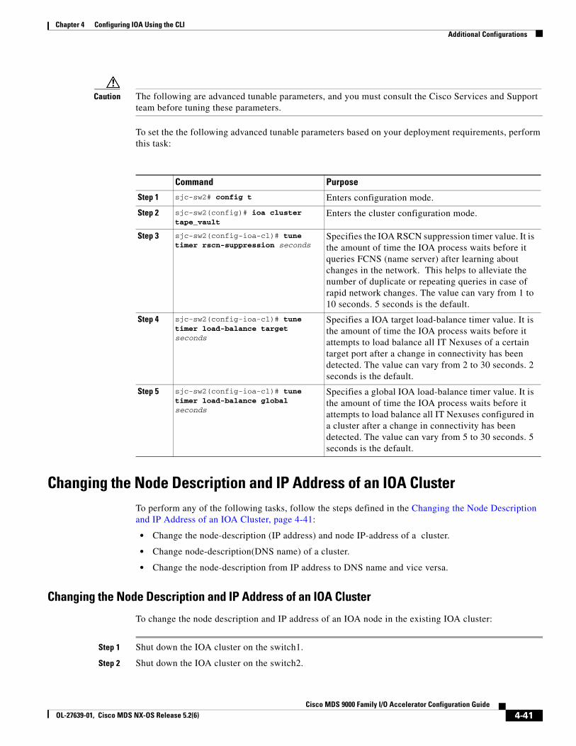
Chapter 4 Configuring IOA Using the CLIAdditional Configurations
Caution The following are advanced tunable parameters, and you must consult the Cisco Services and Support team before tuning these parameters.
To set the the following advanced tunable parameters based on your deployment requirements, perform this task:
Command Purpose
Step 1 sjc-sw2# config t Enters configuration mode.
Step 2 sjc-sw2(config)# ioa cluster tape_vault
Enters the cluster configuration mode.
Step 3 sjc-sw2(config-ioa-cl)# tune timer rscn-suppression seconds
Specifies the IOA RSCN suppression timer value. It is the amount of time the IOA process waits before it queries FCNS (name server) after learning about changes in the network. This helps to alleviate the number of duplicate or repeating queries in case of rapid network changes. The value can vary from 1 to 10 seconds. 5 seconds is the default.
Step 4 sjc-sw2(config-ioa-cl)# tune timer load-balance target seconds
Specifies a IOA target load-balance timer value. It is the amount of time the IOA process waits before it attempts to load balance all IT Nexuses of a certain target port after a change in connectivity has been detected. The value can vary from 2 to 30 seconds. 2 seconds is the default.
Step 5 sjc-sw2(config-ioa-cl)# tune timer load-balance global seconds
Specifies a global IOA load-balance timer value. It is the amount of time the IOA process waits before it attempts to load balance all IT Nexuses configured in a cluster after a change in connectivity has been detected. The value can vary from 5 to 30 seconds. 5 seconds is the default.
Changing the Node Description and IP Address of an IOA ClusterTo perform any of the following tasks, follow the steps defined in the Changing the Node Description and IP Address of an IOA Cluster, page 4-41:
• Change the node-description (IP address) and node IP-address of a cluster.
• Change node-description(DNS name) of a cluster.
• Change the node-description from IP address to DNS name and vice versa.
Changing the Node Description and IP Address of an IOA Cluster
To change the node description and IP address of an IOA node in the existing IOA cluster:
Step 1 Shut down the IOA cluster on the switch1.
Step 2 Shut down the IOA cluster on the switch2.
4-41Cisco MDS 9000 Family I/O Accelerator Configuration Guide
OL-27639-01, Cisco MDS NX-OS Release 5.2(6)
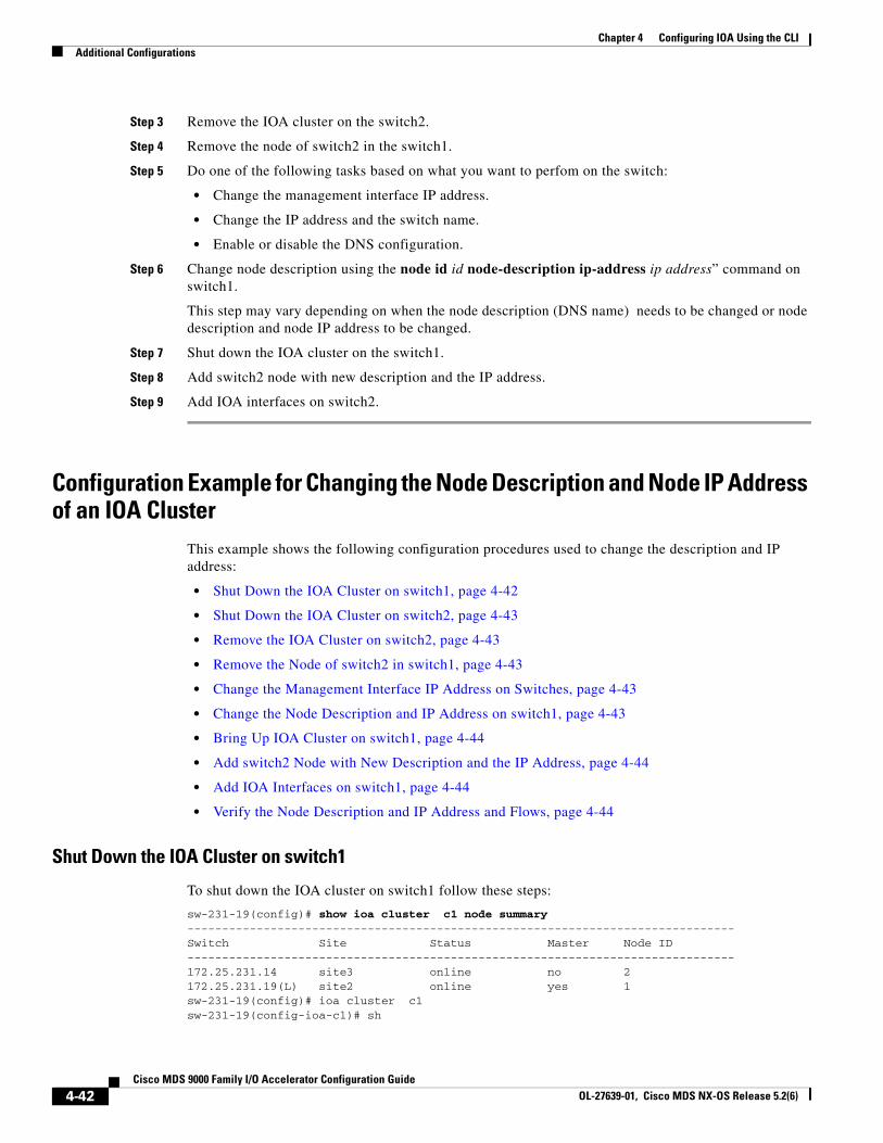
Chapter 4 Configuring IOA Using the CLI Additional Configurations
Step 3 Remove the IOA cluster on the switch2.
Step 4 Remove the node of switch2 in the switch1.
Step 5 Do one of the following tasks based on what you want to perfom on the switch:
• Change the management interface IP address.
• Change the IP address and the switch name.
• Enable or disable the DNS configuration.
Step 6 Change node description using the node id id node-description ip-address ip address” command on switch1.
This step may vary depending on when the node description (DNS name) needs to be changed or node description and node IP address to be changed.
Step 7 Shut down the IOA cluster on the switch1.
Step 8 Add switch2 node with new description and the IP address.
Step 9 Add IOA interfaces on switch2.
Configuration Example for Changing the Node Description and Node IP Address of an IOA Cluster
This example shows the following configuration procedures used to change the description and IP address:
• Shut Down the IOA Cluster on switch1, page 4-42
• Shut Down the IOA Cluster on switch2, page 4-43
• Remove the IOA Cluster on switch2, page 4-43
• Remove the Node of switch2 in switch1, page 4-43
• Change the Management Interface IP Address on Switches, page 4-43
• Change the Node Description and IP Address on switch1, page 4-43
• Bring Up IOA Cluster on switch1, page 4-44
• Add switch2 Node with New Description and the IP Address, page 4-44
• Add IOA Interfaces on switch1, page 4-44
• Verify the Node Description and IP Address and Flows, page 4-44
Shut Down the IOA Cluster on switch1
To shut down the IOA cluster on switch1 follow these steps:
sw-231-19(config)# show ioa cluster c1 node summary-------------------------------------------------------------------------------Switch Site Status Master Node ID-------------------------------------------------------------------------------172.25.231.14 site3 online no 2172.25.231.19(L) site2 online yes 1sw-231-19(config)# ioa cluster c1sw-231-19(config-ioa-cl)# sh
4-42Cisco MDS 9000 Family I/O Accelerator Configuration Guide
OL-27639-01, Cisco MDS NX-OS Release 5.2(6)
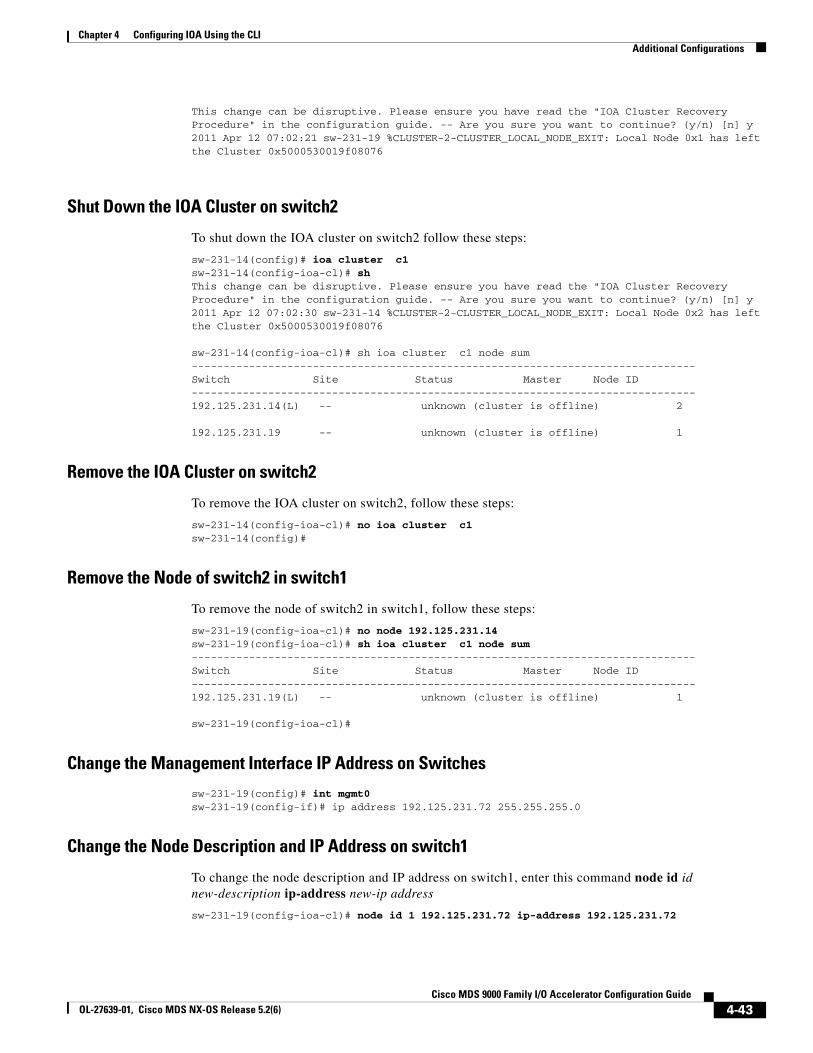
Chapter 4 Configuring IOA Using the CLIAdditional Configurations
This change can be disruptive. Please ensure you have read the "IOA Cluster Recovery Procedure" in the configuration guide. -- Are you sure you want to continue? (y/n) [n] y2011 Apr 12 07:02:21 sw-231-19 %CLUSTER-2-CLUSTER_LOCAL_NODE_EXIT: Local Node 0x1 has left the Cluster 0x5000530019f08076
Shut Down the IOA Cluster on switch2
To shut down the IOA cluster on switch2 follow these steps:
sw-231-14(config)# ioa cluster c1sw-231-14(config-ioa-cl)# shThis change can be disruptive. Please ensure you have read the "IOA Cluster Recovery Procedure" in the configuration guide. -- Are you sure you want to continue? (y/n) [n] y2011 Apr 12 07:02:30 sw-231-14 %CLUSTER-2-CLUSTER_LOCAL_NODE_EXIT: Local Node 0x2 has left the Cluster 0x5000530019f08076
sw-231-14(config-ioa-cl)# sh ioa cluster c1 node sum-------------------------------------------------------------------------------Switch Site Status Master Node ID-------------------------------------------------------------------------------192.125.231.14(L) -- unknown (cluster is offline) 2
192.125.231.19 -- unknown (cluster is offline) 1
Remove the IOA Cluster on switch2
To remove the IOA cluster on switch2, follow these steps:
sw-231-14(config-ioa-cl)# no ioa cluster c1sw-231-14(config)#
Remove the Node of switch2 in switch1
To remove the node of switch2 in switch1, follow these steps:
sw-231-19(config-ioa-cl)# no node 192.125.231.14sw-231-19(config-ioa-cl)# sh ioa cluster c1 node sum-------------------------------------------------------------------------------Switch Site Status Master Node ID-------------------------------------------------------------------------------192.125.231.19(L) -- unknown (cluster is offline) 1
sw-231-19(config-ioa-cl)#
Change the Management Interface IP Address on Switches
sw-231-19(config)# int mgmt0sw-231-19(config-if)# ip address 192.125.231.72 255.255.255.0
Change the Node Description and IP Address on switch1
To change the node description and IP address on switch1, enter this command node id id new-description ip-address new-ip address
sw-231-19(config-ioa-cl)# node id 1 192.125.231.72 ip-address 192.125.231.72
4-43Cisco MDS 9000 Family I/O Accelerator Configuration Guide
OL-27639-01, Cisco MDS NX-OS Release 5.2(6)
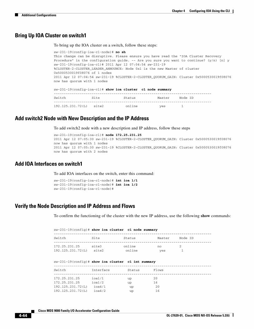
Chapter 4 Configuring IOA Using the CLI Additional Configurations
Bring Up IOA Cluster on switch1
To bring up the IOA cluster on a switch, follow these steps:
sw-231-19(config-ioa-cl-node)# no shThis change can be disruptive. Please ensure you have read the "IOA Cluster Recovery Procedure" in the configuration guide. -- Are you sure you want to continue? (y/n) [n] ysw-231-19(config-ioa-cl)# 2011 Apr 12 07:04:54 sw-231-19 %CLUSTER-2-CLUSTER_LEADER_ANNOUNCE: Node 0x1 is the new Master of cluster 0x5000530019f08076 of 1 nodes2011 Apr 12 07:04:54 sw-231-19 %CLUSTER-2-CLUSTER_QUORUM_GAIN: Cluster 0x5000530019f08076 now has quorum with 1 nodes
sw-231-19(config-ioa-cl)# show ioa cluster c1 node summary-------------------------------------------------------------------------------Switch Site Status Master Node ID-------------------------------------------------------------------------------192.125.231.72(L) site2 online yes 1
Add switch2 Node with New Description and the IP Address
To add switch2 node with a new description and IP address, follow these steps
sw-231-19(config-ioa-cl)# node 172.25.231.252011 Apr 12 07:05:30 sw-231-19 %CLUSTER-2-CLUSTER_QUORUM_GAIN: Cluster 0x5000530019f08076 now has quorum with 1 nodes2011 Apr 12 07:05:30 sw-231-19 %CLUSTER-2-CLUSTER_QUORUM_GAIN: Cluster 0x5000530019f08076 now has quorum with 2 nodes
Add IOA Interfaces on switch1
To add IOA interfaces on the switch, enter this command:
sw-231-19(config-ioa-cl-node)# int ioa 1/1sw-231-19(config-ioa-cl-node)# int ioa 1/2sw-231-19(config-ioa-cl-node)#
Verify the Node Description and IP Address and Flows
To confirm the functioning of the cluster with the new IP address, use the following show commands:
sw-231-19(config)# show ioa cluster c1 node summary-------------------------------------------------------------------------------Switch Site Status Master Node ID-------------------------------------------------------------------------------172.25.231.25 site3 online no 2192.125.231.72(L) site2 online yes 1
sw-231-19(config)# show ioa cluster c1 int summary-------------------------------------------------------------------------------Switch Interface Status Flows-------------------------------------------------------------------------------172.25.231.25 ioa1/1 up 20172.25.231.25 ioa1/2 up 16192.125.231.72(L) ioa4/1 up 20192.125.231.72(L) ioa4/2 up 16
4-44Cisco MDS 9000 Family I/O Accelerator Configuration Guide
OL-27639-01, Cisco MDS NX-OS Release 5.2(6)
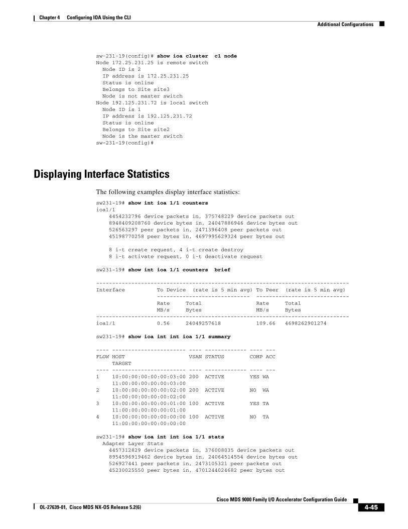
Chapter 4 Configuring IOA Using the CLIAdditional Configurations
sw-231-19(config)# show ioa cluster c1 nodeNode 172.25.231.25 is remote switch Node ID is 2 IP address is 172.25.231.25 Status is online Belongs to Site site3 Node is not master switchNode 192.125.231.72 is local switch Node ID is 1 IP address is 192.125.231.72 Status is online Belongs to Site site2 Node is the master switchsw-231-19(config)#
Displaying Interface StatisticsThe following examples display interface statistics:
sw231-19# show int ioa 1/1 countersioa1/1 4454232796 device packets in, 375748229 device packets out 8948409208760 device bytes in, 24047886946 device bytes out 526563297 peer packets in, 2471396408 peer packets out 45198770258 peer bytes in, 4697995629324 peer bytes out
8 i-t create request, 4 i-t create destroy 8 i-t activate request, 0 i-t deactivate request
sw231-19# show int ioa 1/1 counters brief
-------------------------------------------------------------------------------Interface To Device (rate is 5 min avg) To Peer (rate is 5 min avg) ----------------------------- ----------------------------- Rate Total Rate Total MB/s Bytes MB/s Bytes-------------------------------------------------------------------------------ioa1/1 0.56 24049257618 109.66 4698262901274
sw231-19# show ioa int int ioa 1/1 summary
---- ----------------------- ---- ------------- ---- ---FLOW HOST VSAN STATUS COMP ACC TARGET---- ----------------------- ---- ------------- ---- ---1 10:00:00:00:00:00:03:00 200 ACTIVE YES WA 11:00:00:00:00:00:03:002 10:00:00:00:00:00:02:00 200 ACTIVE NO WA 11:00:00:00:00:00:02:003 10:00:00:00:00:00:01:00 100 ACTIVE YES TA 11:00:00:00:00:00:01:004 10:00:00:00:00:00:00:00 100 ACTIVE NO TA 11:00:00:00:00:00:00:00
sw231-19# show ioa int int ioa 1/1 stats Adapter Layer Stats 4457312829 device packets in, 376008035 device packets out 8954596919462 device bytes in, 24064514554 device bytes out 526927441 peer packets in, 2473105321 peer packets out 45230025550 peer bytes in, 4701244024682 peer bytes out
4-45Cisco MDS 9000 Family I/O Accelerator Configuration Guide
OL-27639-01, Cisco MDS NX-OS Release 5.2(6)
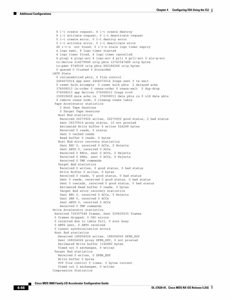
Chapter 4 Configuring IOA Using the CLI Additional Configurations
8 i-t create request, 4 i-t create destroy 8 i-t activate request, 0 i-t deactivate request 0 i-t create error, 0 i-t destroy error 0 i-t activate error, 0 i-t deactivate error 48 i-t-n not found, 0 i-t-n stale logo timer expiry 4 logo sent, 8 logo timer started 4 logo timer fired, 4 logo timer cancelled 4 plogi 4 plogi-acc 4 logo-acc 4 prli 4 prli-acc 0 els-q-err to-device 214279940 orig pkts 12743547488 orig bytes to-peer 8748538 orig pkts 682386268 orig bytes 0 queued 0 flushed 0 discarded LRTP Stats 0 retransmitted pkts, 0 flow control 2464072014 app sent 2464072014 frags sent 0 tx wait 0 rexmt bulk attempts 0 rexmt bulk pkts 2 delayed acks 376008013 in-order 0 reass-order 0 reass-wait 0 dup-drop 376008013 app deliver 376008013 frags rcvd 150919428 pure acks rx 376008013 data pkts rx 0 old data pkts 0 remove reass node, 0 cleanup reass table Tape Accelerator statistics 2 Host Tape Sessions 0 Target Tape Sessions Host End statistics Received 26275926 writes, 26275920 good status, 2 bad status Sent 26275914 proxy status, 10 not proxied Estimated Write buffer 4 writes 524288 bytes Received 0 reads, 0 status Sent 0 cached reads Read buffer 0 reads, 0 bytes Host End error recovery statistics Sent REC 0, received 0 ACCs, 0 Rejects Sent ABTS 0, received 0 ACCs Received 0 RECs, sent 0 ACCs, 0 Rejects Received 0 SRRs, sent 0 ACCs, 0 Rejects Received 0 TMF commands Target End statistics Received 0 writes, 0 good status, 0 bad status Write Buffer 0 writes, 0 bytes Received 0 reads, 0 good status, 0 bad status Sent 0 reads, received 0 good status, 0 bad status Sent 0 rewinds, received 0 good status, 0 bad status Estimated Read buffer 0 reads, 0 bytes Target End error recovery statistics Sent REC 0, received 0 ACCs, 0 Rejects Sent SRR 0, received 0 ACCs Sent ABTS 0, received 0 ACCs Received 0 TMF commands Write Accelerator statistics Received 726357548 frames, Sent 529605035 frames 0 frames dropped, 0 CRC errors 0 rejected due to table full, 0 scsi busy 0 ABTS sent, 0 ABTS received 0 tunnel synchronization errors Host End statistics Received 188004026 writes, 188004000 XFER_RDY Sent 188004026 proxy XFER_RDY, 0 not proxied Estimated Write buffer 1146880 bytes Timed out 0 exchanges, 0 writes Target End statistics Received 0 writes, 0 XFER_RDY Write buffer 0 bytes TCP flow control 0 times, 0 bytes current Timed out 0 exchanges, 0 writes Compression Statistics
4-46Cisco MDS 9000 Family I/O Accelerator Configuration Guide
OL-27639-01, Cisco MDS NX-OS Release 5.2(6)
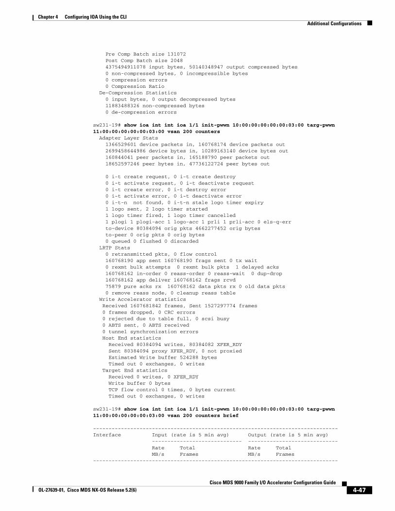
Chapter 4 Configuring IOA Using the CLIAdditional Configurations
Pre Comp Batch size 131072 Post Comp Batch size 2048 4375494911078 input bytes, 50140348947 output compressed bytes 0 non-compressed bytes, 0 incompressible bytes 0 compression errors 0 Compression Ratio De-Compression Statistics 0 input bytes, 0 output decompressed bytes 11883488326 non-compressed bytes 0 de-compression errors
sw231-19# show ioa int int ioa 1/1 init-pwwn 10:00:00:00:00:00:03:00 targ-pwwn 11:00:00:00:00:00:03:00 vsan 200 counters Adapter Layer Stats 1366529601 device packets in, 160768174 device packets out 2699458644986 device bytes in, 10289163140 device bytes out 160844041 peer packets in, 165188790 peer packets out 18652597246 peer bytes in, 47736122724 peer bytes out
0 i-t create request, 0 i-t create destroy 0 i-t activate request, 0 i-t deactivate request 0 i-t create error, 0 i-t destroy error 0 i-t activate error, 0 i-t deactivate error 0 i-t-n not found, 0 i-t-n stale logo timer expiry 1 logo sent, 2 logo timer started 1 logo timer fired, 1 logo timer cancelled 1 plogi 1 plogi-acc 1 logo-acc 1 prli 1 prli-acc 0 els-q-err to-device 80384094 orig pkts 4662277452 orig bytes to-peer 0 orig pkts 0 orig bytes 0 queued 0 flushed 0 discarded LRTP Stats 0 retransmitted pkts, 0 flow control 160768190 app sent 160768190 frags sent 0 tx wait 0 rexmt bulk attempts 0 rexmt bulk pkts 1 delayed acks 160768162 in-order 0 reass-order 0 reass-wait 0 dup-drop 160768162 app deliver 160768162 frags rcvd 75879 pure acks rx 160768162 data pkts rx 0 old data pkts 0 remove reass node, 0 cleanup reass table Write Accelerator statistics Received 1607681842 frames, Sent 1527297774 frames 0 frames dropped, 0 CRC errors 0 rejected due to table full, 0 scsi busy 0 ABTS sent, 0 ABTS received 0 tunnel synchronization errors Host End statistics Received 80384094 writes, 80384082 XFER_RDY Sent 80384094 proxy XFER_RDY, 0 not proxied Estimated Write buffer 524288 bytes Timed out 0 exchanges, 0 writes Target End statistics Received 0 writes, 0 XFER_RDY Write buffer 0 bytes TCP flow control 0 times, 0 bytes current Timed out 0 exchanges, 0 writes
sw231-19# show ioa int int ioa 1/1 init-pwwn 10:00:00:00:00:00:03:00 targ-pwwn 11:00:00:00:00:00:03:00 vsan 200 counters brief
-------------------------------------------------------------------------------Interface Input (rate is 5 min avg) Output (rate is 5 min avg) ----------------------------- ----------------------------- Rate Total Rate Total MB/s Frames MB/s Frames-------------------------------------------------------------------------------
4-47Cisco MDS 9000 Family I/O Accelerator Configuration Guide
OL-27639-01, Cisco MDS NX-OS Release 5.2(6)

Chapter 4 Configuring IOA Using the CLI Additional Configurations
ioa1/1Device 60 9573683 0 1126308Peer 0 1126833 1 1157161sjc-sw2#
4-48Cisco MDS 9000 Family I/O Accelerator Configuration Guide
OL-27639-01, Cisco MDS NX-OS Release 5.2(6)
Cisco MOL-27639-01, Cisco MDS NX-OS Release 5.2(6)
C H A P T E R 5
Configuring IOA Using Cisco DCNM-SANThis chapter describes how to configure I/O Accelerator (IOA) using Cisco DCNM-SAN.
This chapter contains the following sections:
• IOA Manager, page 5-1
• Launching IOA Manager, page 5-3
• Launching IOA Manager, page 5-3
• Configuring Clusters, page 5-7
• Configuring Interfaces, page 5-11
• Configuring Flows, page 5-13
IOA Manager The IOA Manager is a graphical user interface (GUI) for configuring and managing IOA. The IOA Manager user interface consists of a navigation pane on the left that displays a hierarchy and an information pane on the right that displays the contents of the item that you click in the navigation pane. The hierarchy is a tree structure that contains elements that you can configure with IOA Manager. It also consists of a toolbar for quick access to the most commonly used options and a Fabric drop-down list box. The Fabric drop-down list box allows you to directly access the fabrics managed by Cisco DCNM-SAN. The Fabric drop-down list box will be available only if more than one fabric is open.
Note Cisco DCNM-SAN Client standalone supports IOA Manager from Release 5.0(1a).
Note When you perform some of the time-consuming configuration activities using IOA Manager, the progress bar indicates that the configuration actions are in progress. You need to wait until the action is complete. You can click Stop to cancel the action. However, stopping the action may not roll back the transactions that were executed.
Figure 5-1 shows the IOA Manager interface.
5-1DS 9000 Family I/O Accelerator Configuration Guide
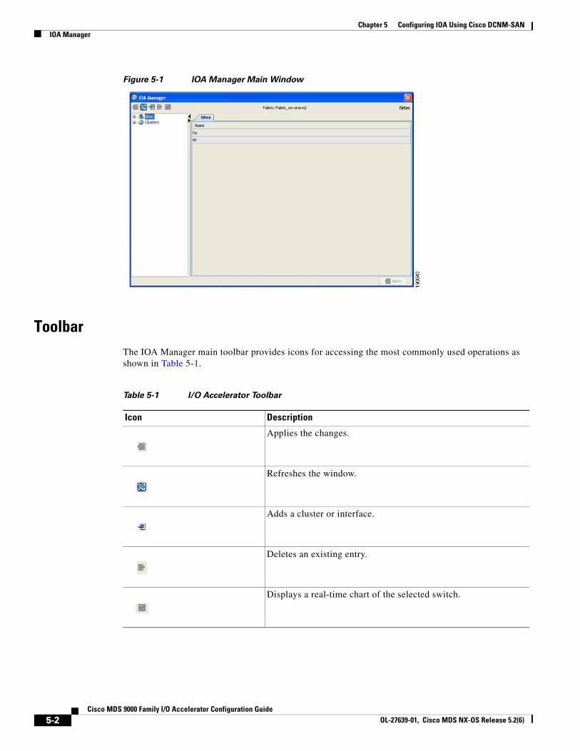
Chapter 5 Configuring IOA Using Cisco DCNM-SAN IOA Manager
Figure 5-1 IOA Manager Main Window
Toolbar The IOA Manager main toolbar provides icons for accessing the most commonly used operations as shown in Table 5-1.
Table 5-1 I/O Accelerator Toolbar
Icon Description
Applies the changes.
Refreshes the window.
Adds a cluster or interface.
Deletes an existing entry.
Displays a real-time chart of the selected switch.
5-2Cisco MDS 9000 Family I/O Accelerator Configuration Guide
OL-27639-01, Cisco MDS NX-OS Release 5.2(6)
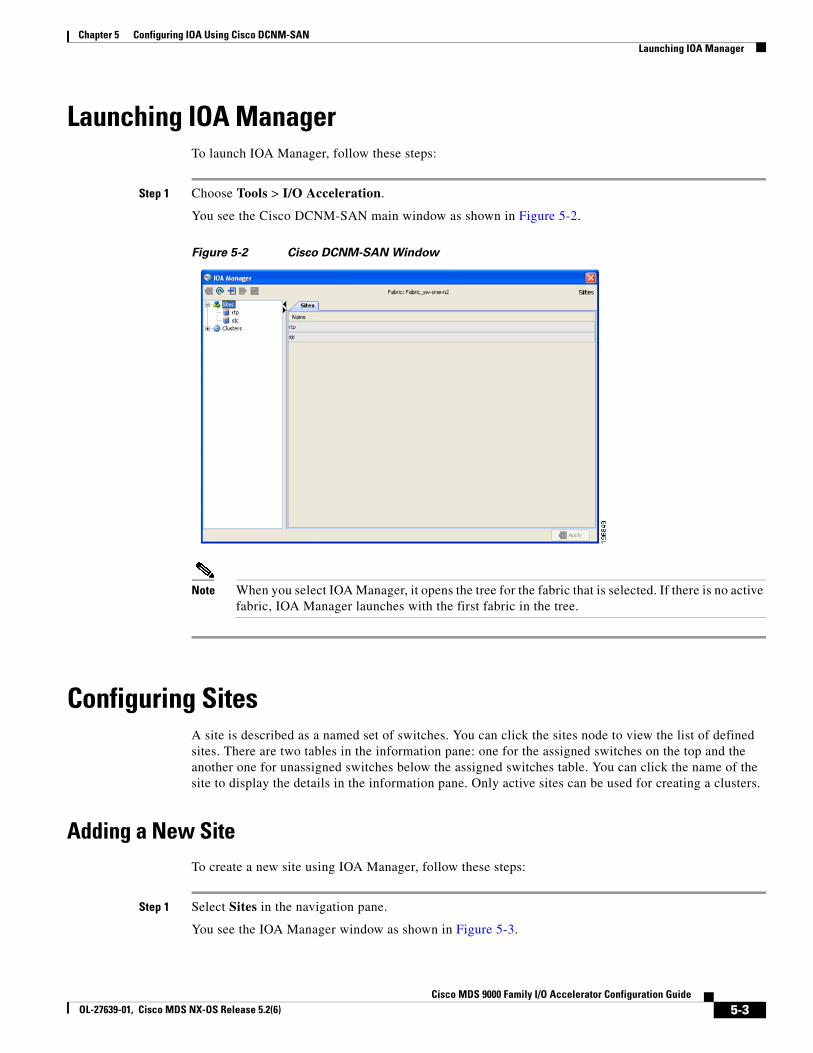
Chapter 5 Configuring IOA Using Cisco DCNM-SANLaunching IOA Manager
Launching IOA ManagerTo launch IOA Manager, follow these steps:
Step 1 Choose Tools > I/O Acceleration.
You see the Cisco DCNM-SAN main window as shown in Figure 5-2.
Figure 5-2 Cisco DCNM-SAN Window
Note When you select IOA Manager, it opens the tree for the fabric that is selected. If there is no active fabric, IOA Manager launches with the first fabric in the tree.
Configuring SitesA site is described as a named set of switches. You can click the sites node to view the list of defined sites. There are two tables in the information pane: one for the assigned switches on the top and the another one for unassigned switches below the assigned switches table. You can click the name of the site to display the details in the information pane. Only active sites can be used for creating a clusters.
Adding a New SiteTo create a new site using IOA Manager, follow these steps:
Step 1 Select Sites in the navigation pane.
You see the IOA Manager window as shown in Figure 5-3.
5-3Cisco MDS 9000 Family I/O Accelerator Configuration Guide
OL-27639-01, Cisco MDS NX-OS Release 5.2(6)
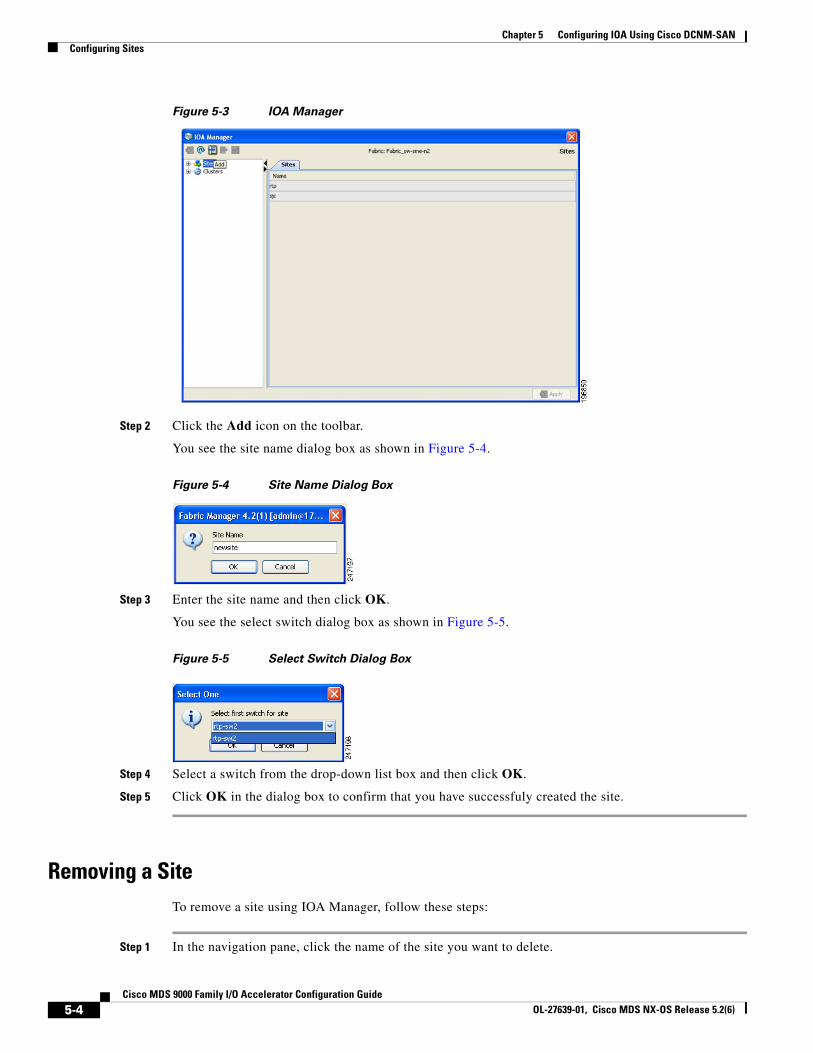
Chapter 5 Configuring IOA Using Cisco DCNM-SAN Configuring Sites
Figure 5-3 IOA Manager
Step 2 Click the Add icon on the toolbar.
You see the site name dialog box as shown in Figure 5-4.
Figure 5-4 Site Name Dialog Box
Step 3 Enter the site name and then click OK.
You see the select switch dialog box as shown in Figure 5-5.
Figure 5-5 Select Switch Dialog Box
Step 4 Select a switch from the drop-down list box and then click OK.
Step 5 Click OK in the dialog box to confirm that you have successfuly created the site.
Removing a SiteTo remove a site using IOA Manager, follow these steps:
Step 1 In the navigation pane, click the name of the site you want to delete.
5-4Cisco MDS 9000 Family I/O Accelerator Configuration Guide
OL-27639-01, Cisco MDS NX-OS Release 5.2(6)
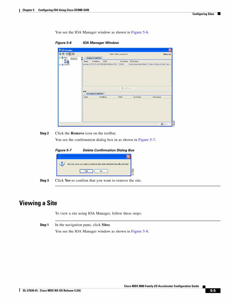
Chapter 5 Configuring IOA Using Cisco DCNM-SANConfiguring Sites
You see the IOA Manager window as shown in Figure 5-6.
Figure 5-6 IOA Manager Window
Step 2 Click the Remove icon on the toolbar.
You see the confirmation dialog box in as shown in Figure 5-7.
Figure 5-7 Delete Confirmation Dialog Box
Step 3 Click Yes to confirm that you want to remove the site.
Viewing a SiteTo view a site using IOA Manager, follow these steps:
Step 1 In the navigation pane, click Sites.
You see the IOA Manager window as shown in Figure 5-8.
5-5Cisco MDS 9000 Family I/O Accelerator Configuration Guide
OL-27639-01, Cisco MDS NX-OS Release 5.2(6)
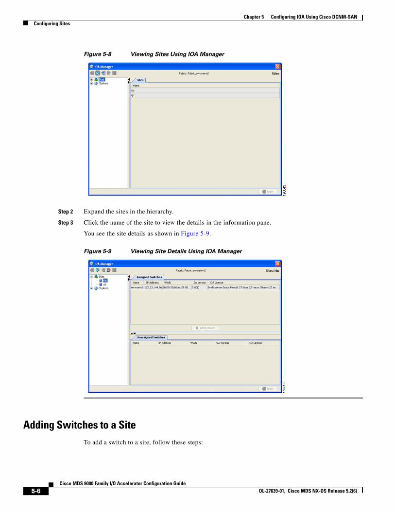
Chapter 5 Configuring IOA Using Cisco DCNM-SAN Configuring Sites
Figure 5-8 Viewing Sites Using IOA Manager
Step 2 Expand the sites in the hierarchy.
Step 3 Click the name of the site to view the details in the information pane.
You see the site details as shown in Figure 5-9.
Figure 5-9 Viewing Site Details Using IOA Manager
Adding Switches to a SiteTo add a switch to a site, follow these steps:
5-6Cisco MDS 9000 Family I/O Accelerator Configuration Guide
OL-27639-01, Cisco MDS NX-OS Release 5.2(6)
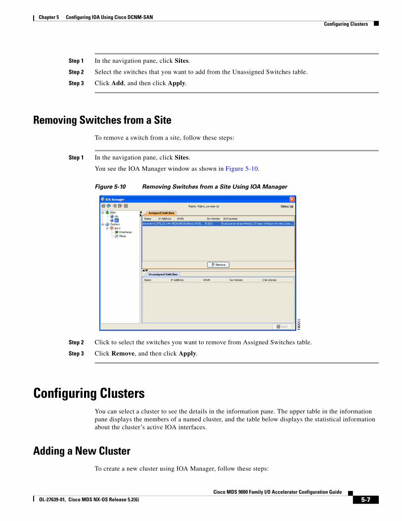
Chapter 5 Configuring IOA Using Cisco DCNM-SANConfiguring Clusters
Step 1 In the navigation pane, click Sites.
Step 2 Select the switches that you want to add from the Unassigned Switches table.
Step 3 Click Add, and then click Apply.
Removing Switches from a SiteTo remove a switch from a site, follow these steps:
Step 1 In the navigation pane, click Sites.
You see the IOA Manager window as shown in Figure 5-10.
Figure 5-10 Removing Switches from a Site Using IOA Manager
Step 2 Click to select the switches you want to remove from Assigned Switches table.
Step 3 Click Remove, and then click Apply.
Configuring ClustersYou can select a cluster to see the details in the information pane. The upper table in the information pane displays the members of a named cluster, and the table below displays the statistical information about the cluster’s active IOA interfaces.
Adding a New ClusterTo create a new cluster using IOA Manager, follow these steps:
5-7Cisco MDS 9000 Family I/O Accelerator Configuration Guide
OL-27639-01, Cisco MDS NX-OS Release 5.2(6)
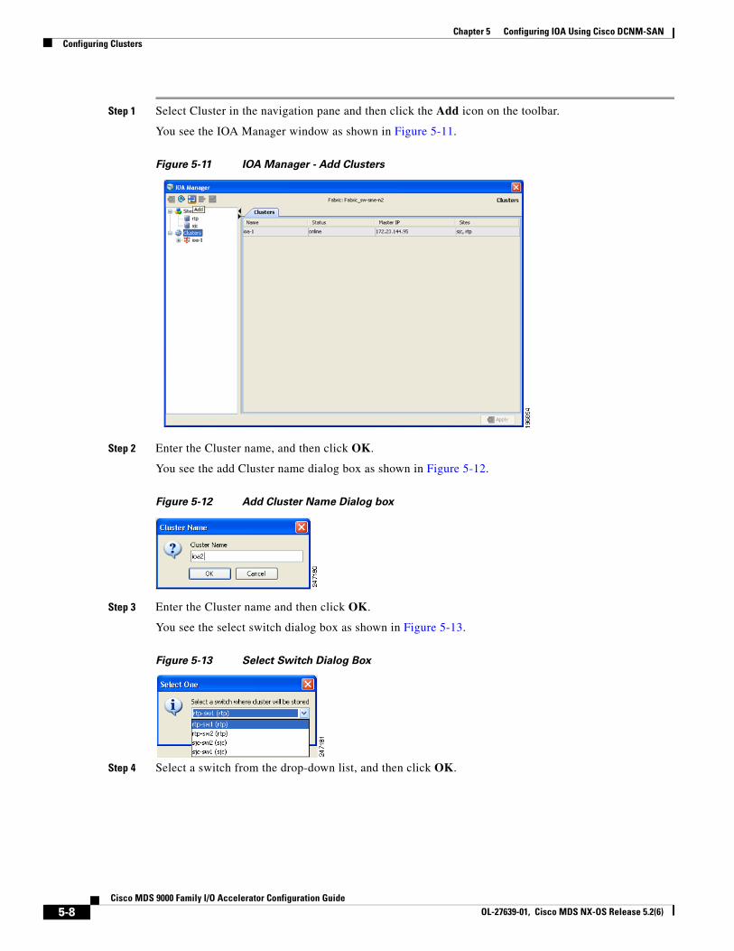
Chapter 5 Configuring IOA Using Cisco DCNM-SAN Configuring Clusters
Step 1 Select Cluster in the navigation pane and then click the Add icon on the toolbar.
You see the IOA Manager window as shown in Figure 5-11.
Figure 5-11 IOA Manager - Add Clusters
Step 2 Enter the Cluster name, and then click OK.
You see the add Cluster name dialog box as shown in Figure 5-12.
Figure 5-12 Add Cluster Name Dialog box
Step 3 Enter the Cluster name and then click OK.
You see the select switch dialog box as shown in Figure 5-13.
Figure 5-13 Select Switch Dialog Box
Step 4 Select a switch from the drop-down list, and then click OK.
5-8Cisco MDS 9000 Family I/O Accelerator Configuration Guide
OL-27639-01, Cisco MDS NX-OS Release 5.2(6)
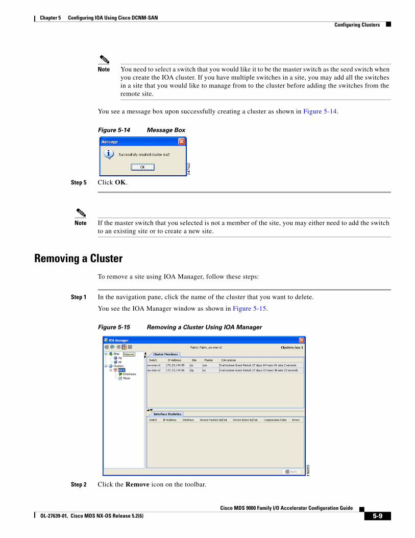
Chapter 5 Configuring IOA Using Cisco DCNM-SANConfiguring Clusters
Note You need to select a switch that you would like it to be the master switch as the seed switch when you create the IOA cluster. If you have multiple switches in a site, you may add all the switches in a site that you would like to manage from to the cluster before adding the switches from the remote site.
You see a message box upon successfully creating a cluster as shown in Figure 5-14.
Figure 5-14 Message Box
Step 5 Click OK.
Note If the master switch that you selected is not a member of the site, you may either need to add the switch to an existing site or to create a new site.
Removing a ClusterTo remove a site using IOA Manager, follow these steps:
Step 1 In the navigation pane, click the name of the cluster that you want to delete.
You see the IOA Manager window as shown in Figure 5-15.
Figure 5-15 Removing a Cluster Using IOA Manager
Step 2 Click the Remove icon on the toolbar.
5-9Cisco MDS 9000 Family I/O Accelerator Configuration Guide
OL-27639-01, Cisco MDS NX-OS Release 5.2(6)
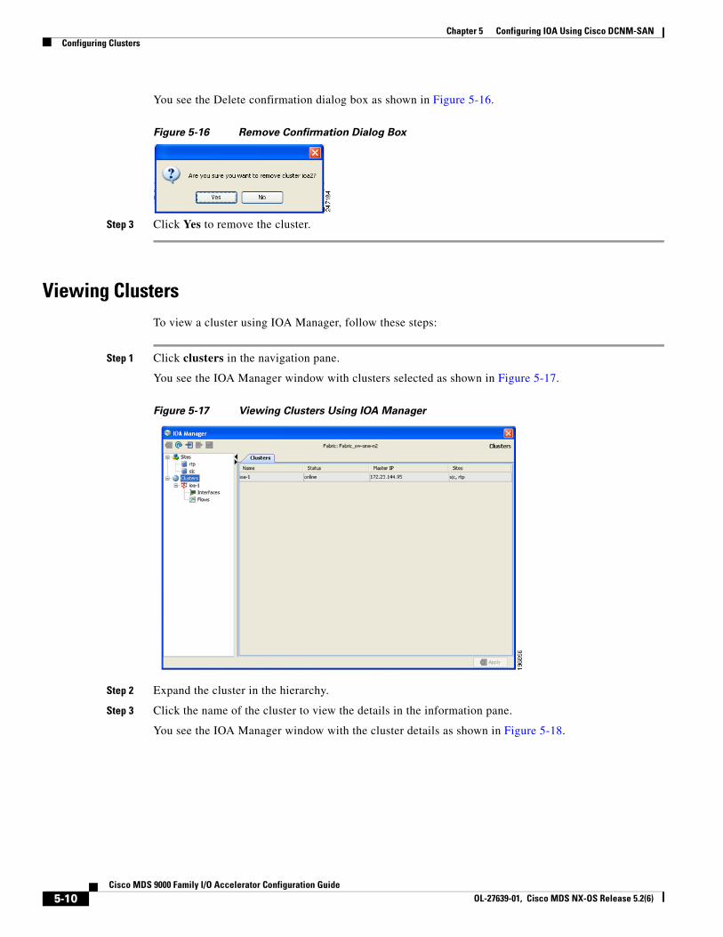
Chapter 5 Configuring IOA Using Cisco DCNM-SAN Configuring Clusters
You see the Delete confirmation dialog box as shown in Figure 5-16.
Figure 5-16 Remove Confirmation Dialog Box
Step 3 Click Yes to remove the cluster.
Viewing ClustersTo view a cluster using IOA Manager, follow these steps:
Step 1 Click clusters in the navigation pane.
You see the IOA Manager window with clusters selected as shown in Figure 5-17.
Figure 5-17 Viewing Clusters Using IOA Manager
Step 2 Expand the cluster in the hierarchy.
Step 3 Click the name of the cluster to view the details in the information pane.
You see the IOA Manager window with the cluster details as shown in Figure 5-18.
5-10Cisco MDS 9000 Family I/O Accelerator Configuration Guide
OL-27639-01, Cisco MDS NX-OS Release 5.2(6)
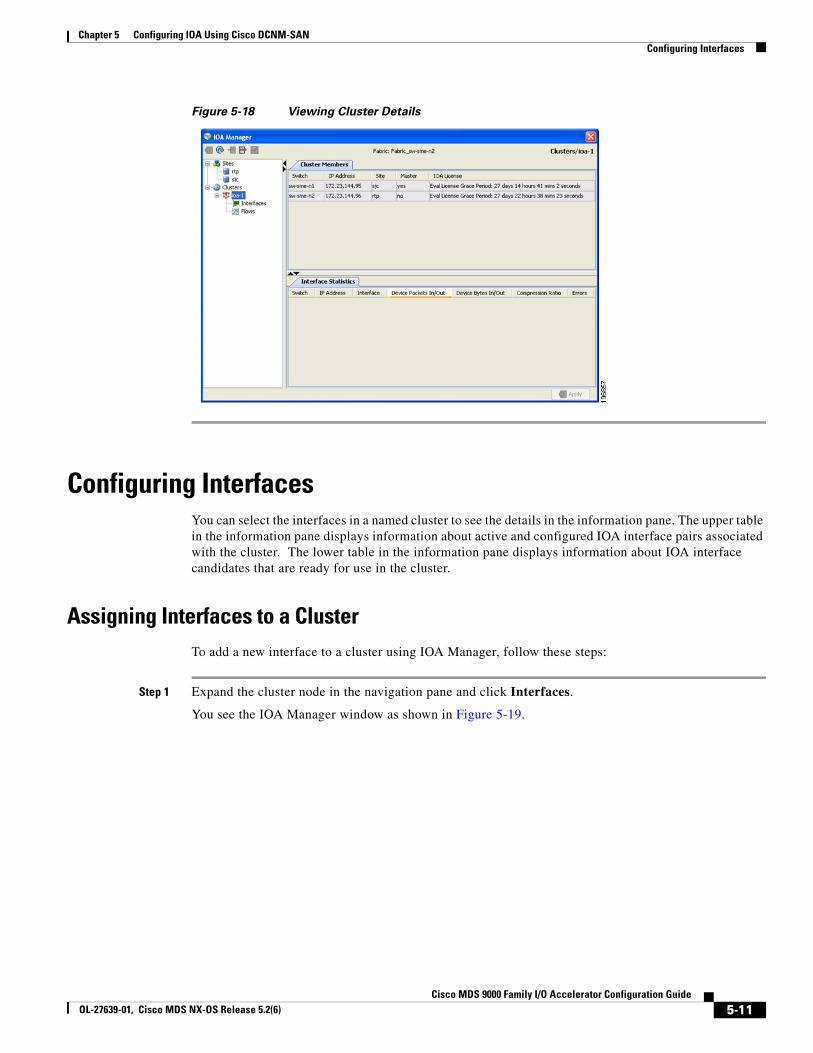
Chapter 5 Configuring IOA Using Cisco DCNM-SANConfiguring Interfaces
Figure 5-18 Viewing Cluster Details
Configuring InterfacesYou can select the interfaces in a named cluster to see the details in the information pane. The upper table in the information pane displays information about active and configured IOA interface pairs associated with the cluster. The lower table in the information pane displays information about IOA interface candidates that are ready for use in the cluster.
Assigning Interfaces to a ClusterTo add a new interface to a cluster using IOA Manager, follow these steps:
Step 1 Expand the cluster node in the navigation pane and click Interfaces.
You see the IOA Manager window as shown in Figure 5-19.
5-11Cisco MDS 9000 Family I/O Accelerator Configuration Guide
OL-27639-01, Cisco MDS NX-OS Release 5.2(6)
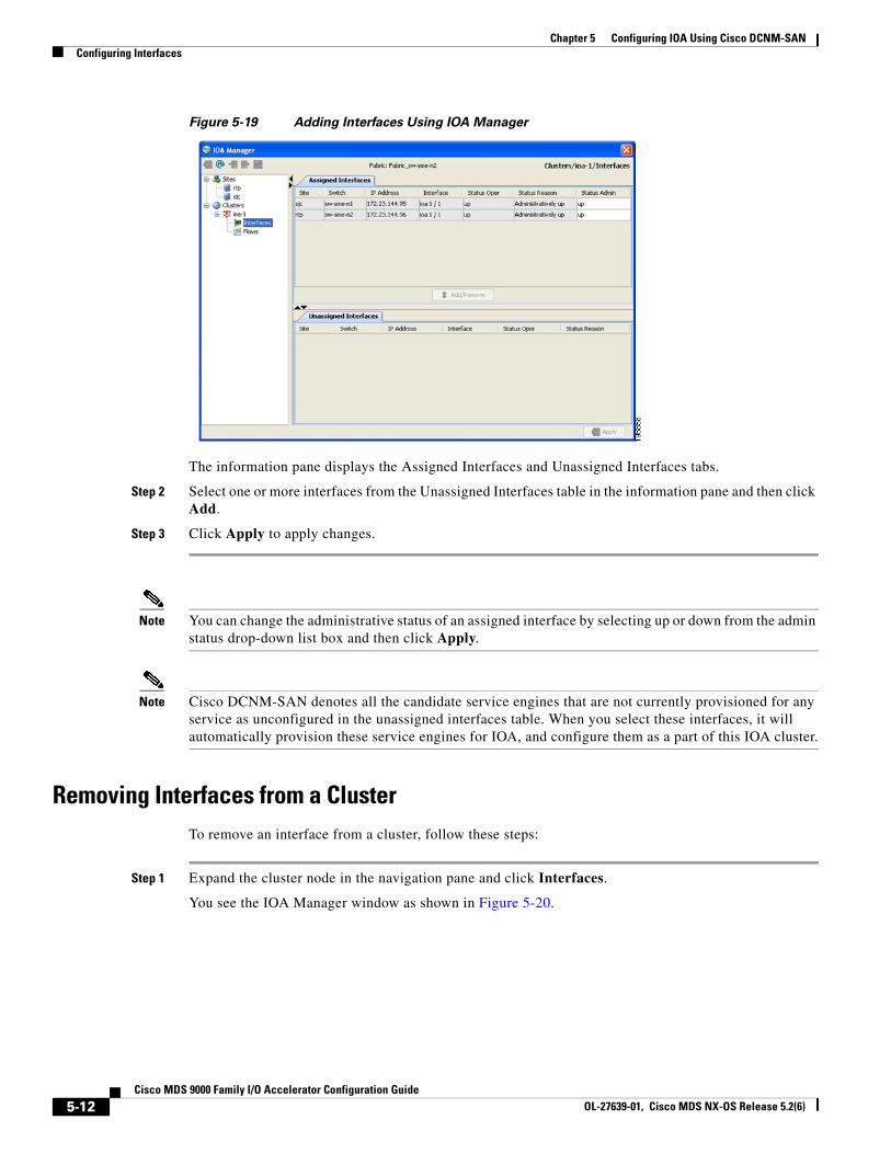
Chapter 5 Configuring IOA Using Cisco DCNM-SAN Configuring Interfaces
Figure 5-19 Adding Interfaces Using IOA Manager
The information pane displays the Assigned Interfaces and Unassigned Interfaces tabs.
Step 2 Select one or more interfaces from the Unassigned Interfaces table in the information pane and then click Add.
Step 3 Click Apply to apply changes.
Note You can change the administrative status of an assigned interface by selecting up or down from the admin status drop-down list box and then click Apply.
Note Cisco DCNM-SAN denotes all the candidate service engines that are not currently provisioned for any service as unconfigured in the unassigned interfaces table. When you select these interfaces, it will automatically provision these service engines for IOA, and configure them as a part of this IOA cluster.
Removing Interfaces from a ClusterTo remove an interface from a cluster, follow these steps:
Step 1 Expand the cluster node in the navigation pane and click Interfaces.
You see the IOA Manager window as shown in Figure 5-20.
5-12Cisco MDS 9000 Family I/O Accelerator Configuration Guide
OL-27639-01, Cisco MDS NX-OS Release 5.2(6)
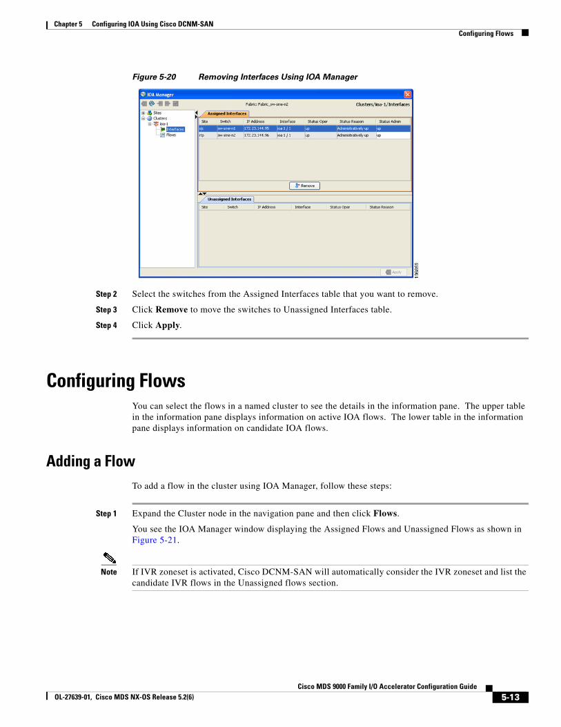
Chapter 5 Configuring IOA Using Cisco DCNM-SANConfiguring Flows
Figure 5-20 Removing Interfaces Using IOA Manager
Step 2 Select the switches from the Assigned Interfaces table that you want to remove.
Step 3 Click Remove to move the switches to Unassigned Interfaces table.
Step 4 Click Apply.
Configuring FlowsYou can select the flows in a named cluster to see the details in the information pane. The upper table in the information pane displays information on active IOA flows. The lower table in the information pane displays information on candidate IOA flows.
Adding a FlowTo add a flow in the cluster using IOA Manager, follow these steps:
Step 1 Expand the Cluster node in the navigation pane and then click Flows.
You see the IOA Manager window displaying the Assigned Flows and Unassigned Flows as shown in Figure 5-21.
Note If IVR zoneset is activated, Cisco DCNM-SAN will automatically consider the IVR zoneset and list the candidate IVR flows in the Unassigned flows section.
5-13Cisco MDS 9000 Family I/O Accelerator Configuration Guide
OL-27639-01, Cisco MDS NX-OS Release 5.2(6)
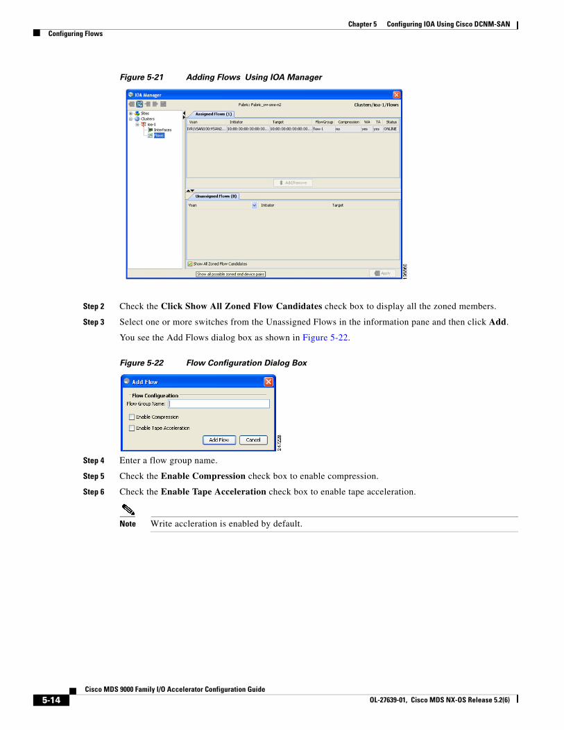
Chapter 5 Configuring IOA Using Cisco DCNM-SAN Configuring Flows
Figure 5-21 Adding Flows Using IOA Manager
Step 2 Check the Click Show All Zoned Flow Candidates check box to display all the zoned members.
Step 3 Select one or more switches from the Unassigned Flows in the information pane and then click Add.
You see the Add Flows dialog box as shown in Figure 5-22.
Figure 5-22 Flow Configuration Dialog Box
Step 4 Enter a flow group name.
Step 5 Check the Enable Compression check box to enable compression.
Step 6 Check the Enable Tape Acceleration check box to enable tape acceleration.
Note Write accleration is enabled by default.
5-14Cisco MDS 9000 Family I/O Accelerator Configuration Guide
OL-27639-01, Cisco MDS NX-OS Release 5.2(6)
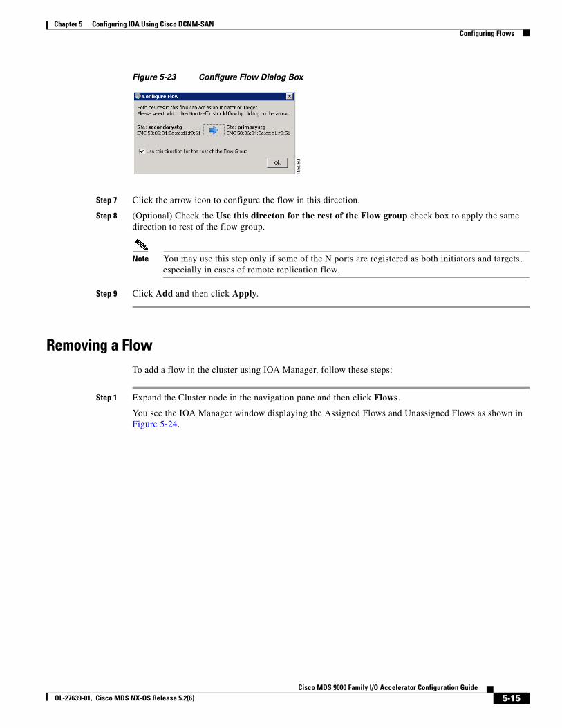
Chapter 5 Configuring IOA Using Cisco DCNM-SANConfiguring Flows
Figure 5-23 Configure Flow Dialog Box
Step 7 Click the arrow icon to configure the flow in this direction.
Step 8 (Optional) Check the Use this directon for the rest of the Flow group check box to apply the same direction to rest of the flow group.
Note You may use this step only if some of the N ports are registered as both initiators and targets, especially in cases of remote replication flow.
Step 9 Click Add and then click Apply.
Removing a FlowTo add a flow in the cluster using IOA Manager, follow these steps:
Step 1 Expand the Cluster node in the navigation pane and then click Flows.
You see the IOA Manager window displaying the Assigned Flows and Unassigned Flows as shown in Figure 5-24.
5-15Cisco MDS 9000 Family I/O Accelerator Configuration Guide
OL-27639-01, Cisco MDS NX-OS Release 5.2(6)
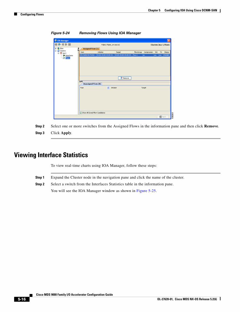
Chapter 5 Configuring IOA Using Cisco DCNM-SAN Configuring Flows
Figure 5-24 Removing Flows Using IOA Manager
Step 2 Select one or more switches from the Assigned Flows in the information pane and then click Remove.
Step 3 Click Apply.
Viewing Interface StatisticsTo view real-time charts using IOA Manager, follow these steps:
Step 1 Expand the Cluster node in the navigation pane and click the name of the cluster.
Step 2 Select a switch from the Interfaces Statistics table in the information pane.
You will see the IOA Manager window as shown in Figure 5-25.
5-16Cisco MDS 9000 Family I/O Accelerator Configuration Guide
OL-27639-01, Cisco MDS NX-OS Release 5.2(6)
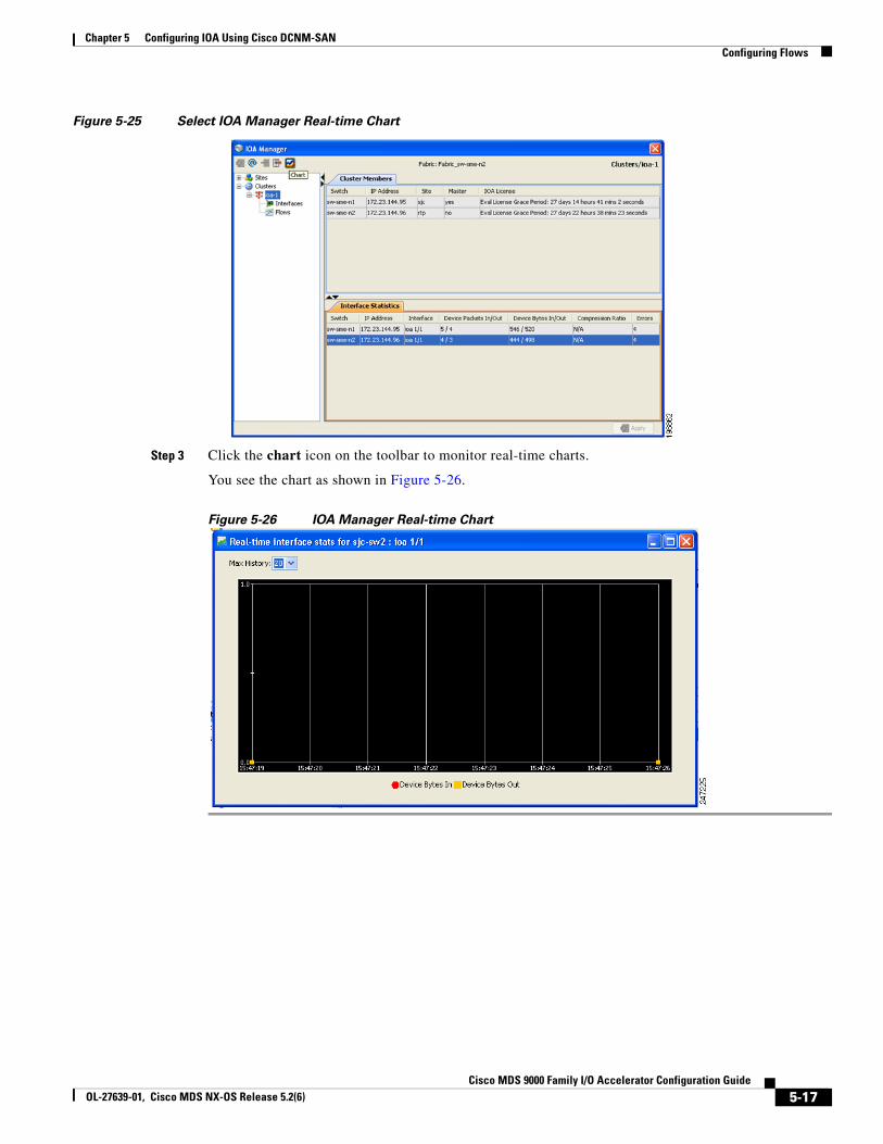
Chapter 5 Configuring IOA Using Cisco DCNM-SANConfiguring Flows
Figure 5-25 Select IOA Manager Real-time Chart
Step 3 Click the chart icon on the toolbar to monitor real-time charts.
You see the chart as shown in Figure 5-26.
Figure 5-26 IOA Manager Real-time Chart
5-17Cisco MDS 9000 Family I/O Accelerator Configuration Guide
OL-27639-01, Cisco MDS NX-OS Release 5.2(6)

Chapter 5 Configuring IOA Using Cisco DCNM-SAN Configuring Flows
5-18Cisco MDS 9000 Family I/O Accelerator Configuration Guide
OL-27639-01, Cisco MDS NX-OS Release 5.2(6)

Cisco MOL-27639-01, Cisco MDS NX-OS Release 5.2(6)
C H A P T E R 6
SCSI Write Acceleration and Tape AccelerationThis appendix describes the concepts of SCSI write acceleration, tape acceleration, and compression.
This appendix includes the following sections:
• SCSI Write Acceleration, page 6-1
• SCSI Tape Acceleration, page 6-2
SCSI Write AccelerationThe SCSI write acceleration feature enables you to significantly improve application write performance when storage traffic is routed over wide area networks using FCIP or Fibre Channel. When write acceleration is enabled, WAN throughput is maximized by minimizing the impact of WAN latency for write operations.
In Figure 6-1, the WRITE command without write acceleration requires two round-trip transfers (RTT), while the WRITE command with write acceleration only requires one RTT. The maximum sized Transfer Ready is sent from the host side of the FCIP or Fibre Channel link back to the host before the WRITE command reaches the target. This enables the host to start sending the write data without waiting for the long latency over the FCIP or Fibre Channel link of the WRITE command and Transfer Ready. It also eliminates the delay caused by multiple Transfer Readys needed for the exchange going over the FCIP or Fibre Channel link.
6-1DS 9000 Family I/O Accelerator Configuration Guide
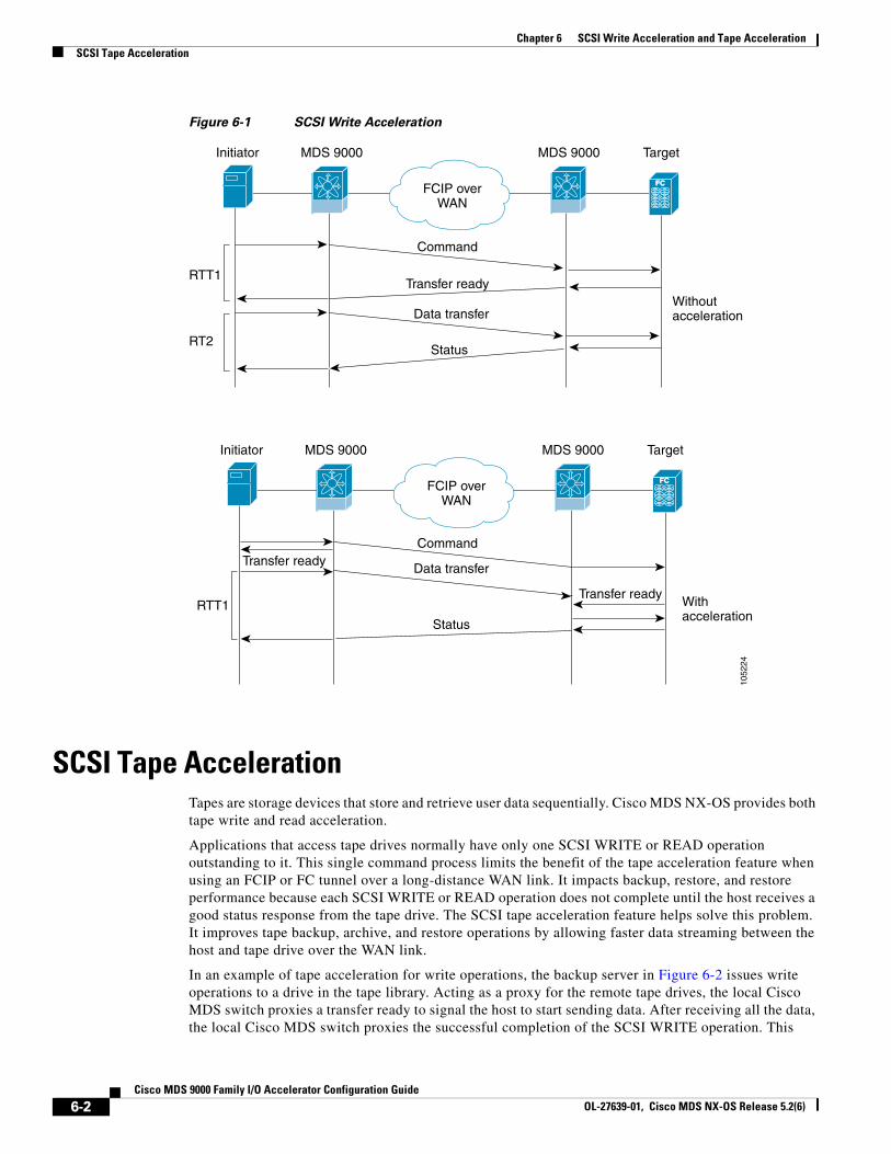
Chapter 6 SCSI Write Acceleration and Tape Acceleration SCSI Tape Acceleration
Figure 6-1 SCSI Write Acceleration
FCFCFCIP overWAN
1052
24
Initiator MDS 9000 MDS 9000 Target
Transfer ready
Transfer ready
Transfer ready
Command
Command
Data transfer
Data transfer
Status
Status
Withoutacceleration
RTT1
RTT1
RT2
FCFCFCIP overWAN
Initiator MDS 9000 MDS 9000 Target
Withacceleration
SCSI Tape AccelerationTapes are storage devices that store and retrieve user data sequentially. Cisco MDS NX-OS provides both tape write and read acceleration.
Applications that access tape drives normally have only one SCSI WRITE or READ operation outstanding to it. This single command process limits the benefit of the tape acceleration feature when using an FCIP or FC tunnel over a long-distance WAN link. It impacts backup, restore, and restore performance because each SCSI WRITE or READ operation does not complete until the host receives a good status response from the tape drive. The SCSI tape acceleration feature helps solve this problem. It improves tape backup, archive, and restore operations by allowing faster data streaming between the host and tape drive over the WAN link.
In an example of tape acceleration for write operations, the backup server in Figure 6-2 issues write operations to a drive in the tape library. Acting as a proxy for the remote tape drives, the local Cisco MDS switch proxies a transfer ready to signal the host to start sending data. After receiving all the data, the local Cisco MDS switch proxies the successful completion of the SCSI WRITE operation. This
6-2Cisco MDS 9000 Family I/O Accelerator Configuration Guide
OL-27639-01, Cisco MDS NX-OS Release 5.2(6)
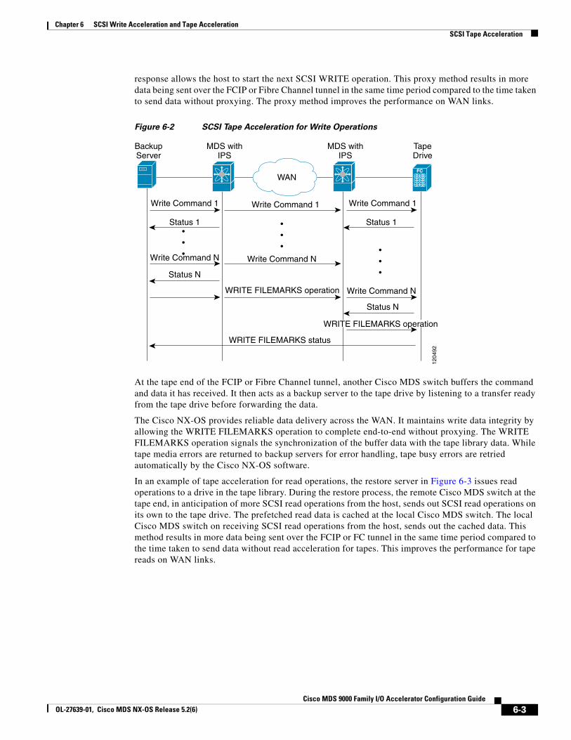
Chapter 6 SCSI Write Acceleration and Tape AccelerationSCSI Tape Acceleration
response allows the host to start the next SCSI WRITE operation. This proxy method results in more data being sent over the FCIP or Fibre Channel tunnel in the same time period compared to the time taken to send data without proxying. The proxy method improves the performance on WAN links.
Figure 6-2 SCSI Tape Acceleration for Write Operations
FCFC
BackupServer
MDS withIPS
MDS withIPS
TapeDrive
Write Command 1 Write Command 1 Write Command 1
Write Command N Write Command N
Write Command N
Status 1 Status 1
Status N
Status N
WAN
WRITE FILEMARKS status
WRITE FILEMARKS operation
WRITE FILEMARKS operation
1204
92
At the tape end of the FCIP or Fibre Channel tunnel, another Cisco MDS switch buffers the command and data it has received. It then acts as a backup server to the tape drive by listening to a transfer ready from the tape drive before forwarding the data.
The Cisco NX-OS provides reliable data delivery across the WAN. It maintains write data integrity by allowing the WRITE FILEMARKS operation to complete end-to-end without proxying. The WRITE FILEMARKS operation signals the synchronization of the buffer data with the tape library data. While tape media errors are returned to backup servers for error handling, tape busy errors are retried automatically by the Cisco NX-OS software.
In an example of tape acceleration for read operations, the restore server in Figure 6-3 issues read operations to a drive in the tape library. During the restore process, the remote Cisco MDS switch at the tape end, in anticipation of more SCSI read operations from the host, sends out SCSI read operations on its own to the tape drive. The prefetched read data is cached at the local Cisco MDS switch. The local Cisco MDS switch on receiving SCSI read operations from the host, sends out the cached data. This method results in more data being sent over the FCIP or FC tunnel in the same time period compared to the time taken to send data without read acceleration for tapes. This improves the performance for tape reads on WAN links.
6-3Cisco MDS 9000 Family I/O Accelerator Configuration Guide
OL-27639-01, Cisco MDS NX-OS Release 5.2(6)
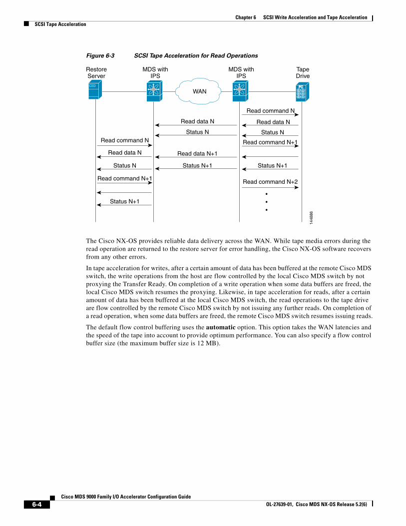
Chapter 6 SCSI Write Acceleration and Tape Acceleration SCSI Tape Acceleration
Figure 6-3 SCSI Tape Acceleration for Read Operations
FCFCFC
RestoreServer
MDS withIPS
MDS withIPS
TapeDrive
WAN
1448
86
Read data N
Read data N+1
Status N
Status N+1
Read command N
Read command N
Read command N+1
Read command N+1
Read command N+2
Read data N
Read data N
Status N
Status N
Status N+1
Status N+1
The Cisco NX-OS provides reliable data delivery across the WAN. While tape media errors during the read operation are returned to the restore server for error handling, the Cisco NX-OS software recovers from any other errors.
In tape acceleration for writes, after a certain amount of data has been buffered at the remote Cisco MDS switch, the write operations from the host are flow controlled by the local Cisco MDS switch by not proxying the Transfer Ready. On completion of a write operation when some data buffers are freed, the local Cisco MDS switch resumes the proxying. Likewise, in tape acceleration for reads, after a certain amount of data has been buffered at the local Cisco MDS switch, the read operations to the tape drive are flow controlled by the remote Cisco MDS switch by not issuing any further reads. On completion of a read operation, when some data buffers are freed, the remote Cisco MDS switch resumes issuing reads.
The default flow control buffering uses the automatic option. This option takes the WAN latencies and the speed of the tape into account to provide optimum performance. You can also specify a flow control buffer size (the maximum buffer size is 12 MB).
6-4Cisco MDS 9000 Family I/O Accelerator Configuration Guide
OL-27639-01, Cisco MDS NX-OS Release 5.2(6)
CiOL-27639-01, Cisco MDS NX-OS Release 5.2(6)
A
P P E N D I X 1 Cluster Management and Recovery ScenariosThis appendix includes information on cluster management and recovery procedures that are used when one or more switches in a Cisco IOA cluster is offline or when you want to change the master switch assignment from one switch to another switch.
Note The procedures in this appendix describe troubleshooting solutions that use the CLI.
Note The Cisco IOA cluster configuration for an offline switch must be done using the CLI. Cisco IOA cluster configuration for an online switch can be done using Cisco DCNM-SAN or the CLI.
This appendix includes the following sections;
• Cluster Quorum and Master Switch Election, page 1-1
• In-Service Software Upgrade (ISSU) in a Two-Node Cluster, page 1-4
• Supported Topologies, page 1-5
• Cluster Recovery Scenarios, page 1-5
Cluster Quorum and Master Switch ElectionThis section describes the Cisco IOA cluster quorum and the process for electing the master switch in a cluster.
Node ID
Every switch in a cluster has a node ID. Cisco IOA assigns a node ID to every new switch as it is added to the cluster. The switch where the cluster is created is assigned the node ID of 1. This is the master switch. When a new switch is added to the cluster, it is assigned the next available higher node ID. For example, when a second switch is added to the cluster it gets the node ID of 2 and the third switch gets the node ID of 3, and so on.
Cluster View
The cluster view is the set of switches that are part of the operational cluster.
1-1sco MDS 9000 Family I/O Accelerator Configuration Guide
Send documenta t i on comments to dcnm-san -doc feedback@c i sco . com
Appendix 1 Cluster Management and Recovery Scenarios Cluster Quorum and Master Switch Election
Cluster QuorumFor a cluster to be operational, it must include more than half the number of configured switches in the cluster view. In an N-node cluster, N/2 + 1 nodes form a cluster quorum.
If N is even, the cluster quorum requires N/2 nodes and also, the presence of the switch with the lowest node ID.
The quorum logic ensures that in the event of cluster partitions at least one partition can be operational. All other switches are nonoperational. This guarantees the consistency of the cluster.
Master Switch ElectionWhen a cluster is created, the switch on which the cluster is created becomes the cluster master switch. When the master switch fails or is rebooted, another switch takes over as the master switch. The master election logic uses the node ID and the latest cluster configuration to determine which switch in the cluster will become the master switch. The master election logic is described as follows:
• If the master switch fails in an operational cluster, the switch with the next lowest node ID takes over as the master switch. Note that in an operational cluster, all the switches run the same cluster configuration.
– When the previous master switch comes back online and joins the cluster, it does not immediately become the master.
• When all the switches of a cluster are coming up, the switch that has the latest cluster configuration becomes the master switch. If there are multiple switches with the same configuration, the switch with the lowest node ID is chosen to be the master switch.
– Once a master switch is chosen and the cluster is operational (there is a quorum), even if a switch with a lower node ID joins the cluster at a later time, the master switch does not change.
For example, there are three switches S1, S2, and S3 with node IDs 1, 2, and 3, respectively. If switches S2 and S3 form a quorum then switch S2 becomes the master switch. Even if switch S1 with the node ID of 1 comes up and joins the cluster at a later time, switch S2 continues to be the master. However, if switch S2 goes down for any reason, switch S1 will become the master switch.
Two-Switch Cluster Scenarios
According to the cluster quorum logic, a cluster with two configured switches can be operational if both switches are operational or the switch with the lowest node ID is operational.
In the latter case, the switch with the lowest node ID is the master of the one-switch cluster. The other switch could have failed or simply lost connectivity to the operational switch. In either case, the switch with the higher node ID would become nonoperational. If the node with the lower node ID failed, the other switch cannot form an operational cluster.
The examples that follow describe these scenarios. The first three examples consider single switch failures.
1. Assume that in a two-switch cluster with switches S1 (node ID 1) and S2 (node ID 2), S1 is the master (the master has the lower node ID).
When the switches lose connectivity between them, the master switch S1 continues to be operational since it has the lower node ID and can form an (N/2) switch cluster. Switch S2 becomes nonoperational.
1-2Cisco MDS 9000 Family I/O Accelerator Configuration Guide
OL-27639-01, Cisco MDS NX-OS Release 5.2(6)
Send documenta t i on comments to dcnm-san -doc feedback@c i sco . com
Appendix 1 Cluster Management and Recovery ScenariosCluster Quorum and Master Switch Election
2. Assume that in a two-switch cluster with switches S1 (node ID 1) and S2 (node ID 2), S2 is the master (note that the master has the higher node ID because it has the latest configuration when both the switches came online).
When the switches lose connectivity between them, switch S2 becomes nonoperational and S1 takes over as the master to form a 1-switch cluster. This is consistent with the quorum logic in a two-switch cluster (N/2 with lowest node ID).
3. Assume that in a two-switch cluster with switches S1 (node ID 1) and S2 (node ID 2). If S1 fails (regardless of which switch was the master), S2 will also become non-operational as long as S1 is down.
When S1 comes up, S1 and S2 will form a two-switch cluster.
The next set of examples describe reboots of both switches (S1 with node ID 1 and S2 with node ID 2):
Caution If you perform any configuration change on a cluster, you must save the running configuration to the startup configuration by entering the copy running-config startup-config CLI command on all switches before rebooting them. Otherwise, the cluster may not form correctly after the reboot (see example 3.).
1. After a reboot, if both switches S1 and S2 come up about the same time, a two-switch cluster will be formed.
a. If the cluster configurations are the same, S1 (with the lower node ID) will become the master.
b. If the cluster configurations are different, the switch with the latest cluster configuration will become the master.
2. After a reboot, if switch S2 comes up first, it will not be able to form a cluster until S1 also comes up. After that, the algorithm explained in the previous case will be used.
3. After a reboot, if switch S1 comes up first, it will form a one-switch cluster (N/2 with lowest node ID). When S2 comes up, it will join the cluster to form a two-switch cluster.
When S2 comes up and if it happens to have the latest cluster configuration in the startup configuration (this can happen if you did not save the running configuration to the startup configuration on S1 but did so on S2), it will not be able to join the cluster formed by S1.
Caution It is critical that you save the running configuration on all switches before a reboot.
Three-Switch Cluster Scenarios
In a three-switch cluster, the quorum requires two switches to be in the cluster view (N/2 + 1). The examples below explain three scenarios in a three-switch cluster with switches S1 (node ID 1), S2 (node ID 2) and S3 (node ID 3). S1 is the master switch.
1. In a three-switch operational cluster, if switch S3 fails or loses connectivity with the other two switches, then S3 becomes nonoperational. Switches S1 and S2 will form an operational cluster. When S3 comes up again, it will rejoin the cluster.
2. In a three-switch operational cluster, if the master switch S1 fails or loses connectivity with the other two switches, then S1 becomes nonoperational. Switches S2 and S3 will form an operational cluster and S2 will be the master. When S1 comes up again, it will rejoin the cluster. Note that S2 will continue to be the master.
3. If two switches fail, the cluster will become nonoperational.
These examples describe reboots on all switches in the cluster:
1-3Cisco MDS 9000 Family I/O Accelerator Configuration Guide
OL-27639-01, Cisco MDS NX-OS Release 5.2(6)
Send documenta t i on comments to dcnm-san -doc feedback@c i sco . com
Appendix 1 Cluster Management and Recovery Scenarios In-Service Software Upgrade (ISSU) in a Two-Node Cluster
Caution If you perform any configuration change on a cluster, you must save the running configuration to the startup configuration by entering the copy running-config startup-config command on all switches before rebooting them. Otherwise, the cluster may not form correctly after the reboot.
1. After a reboot, if all switches come up at about the same time, first a 2-switch cluster will be formed and later the third switch will be added.
a. If the cluster configurations are the same, S1 (with the lower node ID) will become the master switch and form the 2-switch cluster first; and then add the third switch.
b. If the cluster configurations are different, the switch that is running the latest configuration will become the master switch and then form a 2-switch cluster; and then add the third switch.
2. After a reboot, if the switches come up one at a time, a 2-switch cluster will be formed after the first two switches are up. Later, when the third switch comes online, it will join the cluster.
If the third switch happens to be running the latest cluster configuration in the startup configuration (this can happen if you save the running configuration only on this switch but not on the other two), the third switch will not be able to join the cluster.
Caution It is critical that you save the running configuration on all switches before a reboot.
Four-Switch Cluster Scenarios
The four-switch cluster scenario is very similar to the examples above. The cluster will be operational if the cluster view has at least three switches (N/2 + 1), or if the cluster view has two switches including the switch with the lowest node ID (N/2 with lowest node ID).
In-Service Software Upgrade (ISSU) in a Two-Node ClusterIn-Service Software Upgrade (ISSU) is a comprehensive, transparent software upgrade application that allows you to deploy bug fixes and add new features and services without any disruption to the traffic.
In a cluster comprising of the MDS 9222i Switches as nodes, if the nodes are not able to communicate, then the node having the lowest node identifier (node ID) remains in the cluster while the other node leaves the cluster. However, when an ISSU is performed on a node having the lowest node identifier, a complete loss of the cluster results because both the nodes leave the cluster.
This undesirable situation is addressed in a two-node cluster as follows:
• The upgrading node sends a message to the other node of the intent to leave the cluster. The upgrading node can either be a master node or a slave node.
• The remaining node remains in the cluster and performs the role of the master node if it was a slave node. This node continues to remain in the cluster with the quorum intact.
• After the ISSU is completed and the switches boot up, the upgraded node rejoins the cluster as a slave node.
Note This feature is tied to ISSU logic and no additional commands need to be executed.
1-4Cisco MDS 9000 Family I/O Accelerator Configuration Guide
OL-27639-01, Cisco MDS NX-OS Release 5.2(6)
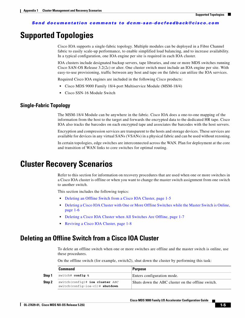
Send documenta t i on comments to dcnm-san -doc feedback@c i sco . com
Appendix 1 Cluster Management and Recovery ScenariosSupported Topologies
Supported TopologiesCisco IOA supports a single-fabric topology. Multiple modules can be deployed in a Fibre Channel fabric to easily scale-up performance, to enable simplified load balancing, and to increase availability. In a typical configuration, one IOA engine per site is required in each IOA cluster.
IOA clusters include designated backup servers, tape libraries, and one or more MDS switches running Cisco SAN-OS Release 3.2(2c) or alter. One cluster switch must include an IOA engine per site. With easy-to-use provisioning, traffic between any host and tape on the fabric can utilize the IOA services.
Required Cisco IOA engines are included in the following Cisco products:
• Cisco MDS 9000 Family 18/4-port Multiservice Module (MSM-18/4)
• Cisco SSN-16 Module Switch
Single-Fabric Topology
The MSM-18/4 Module can be anywhere in the fabric. Cisco IOA does a one-to-one mapping of the information from the host to the target and forwards the encrypted data to the dedicated HR tape. Cisco IOA also tracks the barcodes on each encrypted tape and associates the barcodes with the host servers.
Encryption and compression services are transparent to the hosts and storage devices. These services are available for devices in any virtual SANs (VSANs) in a physical fabric and can be used without rezoning.
In certain topologies, edge switches are interconnected across the WAN. Plan for deployment at the core and transition of WAN links to core switches for optimal routing.
Cluster Recovery ScenariosRefer to this section for information on recovery procedures that are used when one or more switches in a Cisco IOA cluster is offline or when you want to change the master switch assignment from one switch to another switch.
This section includes the following topics:
• Deleting an Offline Switch from a Cisco IOA Cluster, page 1-5
• Deleting a Cisco IOA Cluster with One or More Offline Switches while the Master Switch is Online, page 1-6
• Deleting a Cisco IOA Cluster when All Switches Are Offline, page 1-7
• Reviving a Cisco IOA Cluster, page 1-8
Deleting an Offline Switch from a Cisco IOA ClusterTo delete an offline switch when one or more switches are offline and the master switch is online, use these procedures.
On the offline switch (for example, switch2), shut down the cluster by performing this task:
Command Purpose
Step 1 switch# config t Enters configuration mode.
Step 2 switch(config)# ioa cluster ABCswitch(config-ioa-cl)# shutdown
Shuts down the ABC cluster on the offline switch.
1-5Cisco MDS 9000 Family I/O Accelerator Configuration Guide
OL-27639-01, Cisco MDS NX-OS Release 5.2(6)
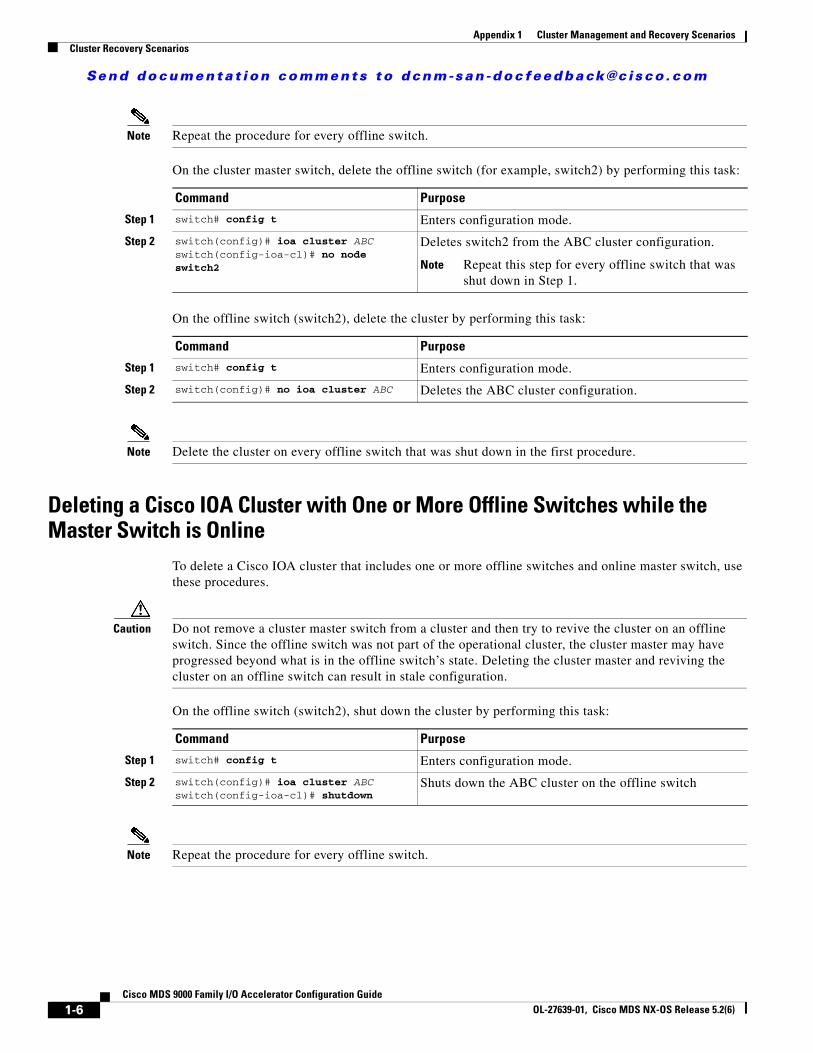
Send documenta t i on comments to dcnm-san -doc feedback@c i sco . com
Appendix 1 Cluster Management and Recovery Scenarios Cluster Recovery Scenarios
Note Repeat the procedure for every offline switch.
On the cluster master switch, delete the offline switch (for example, switch2) by performing this task:
Command Purpose
Step 1 switch# config t Enters configuration mode.
Step 2 switch(config)# ioa cluster ABC switch(config-ioa-cl)# no node switch2
Deletes switch2 from the ABC cluster configuration.
Note Repeat this step for every offline switch that was shut down in Step 1.
On the offline switch (switch2), delete the cluster by performing this task:
Command Purpose
Step 1 switch# config t Enters configuration mode.
Step 2 switch(config)# no ioa cluster ABC Deletes the ABC cluster configuration.
Note Delete the cluster on every offline switch that was shut down in the first procedure.
Deleting a Cisco IOA Cluster with One or More Offline Switches while the Master Switch is Online
To delete a Cisco IOA cluster that includes one or more offline switches and online master switch, use these procedures.
Caution Do not remove a cluster master switch from a cluster and then try to revive the cluster on an offline switch. Since the offline switch was not part of the operational cluster, the cluster master may have progressed beyond what is in the offline switch’s state. Deleting the cluster master and reviving the cluster on an offline switch can result in stale configuration.
On the offline switch (switch2), shut down the cluster by performing this task:
Command Purpose
Step 1 switch# config t Enters configuration mode.
Step 2 switch(config)# ioa cluster ABCswitch(config-ioa-cl)# shutdown
Shuts down the ABC cluster on the offline switch
Note Repeat the procedure for every offline switch.
1-6Cisco MDS 9000 Family I/O Accelerator Configuration Guide
OL-27639-01, Cisco MDS NX-OS Release 5.2(6)
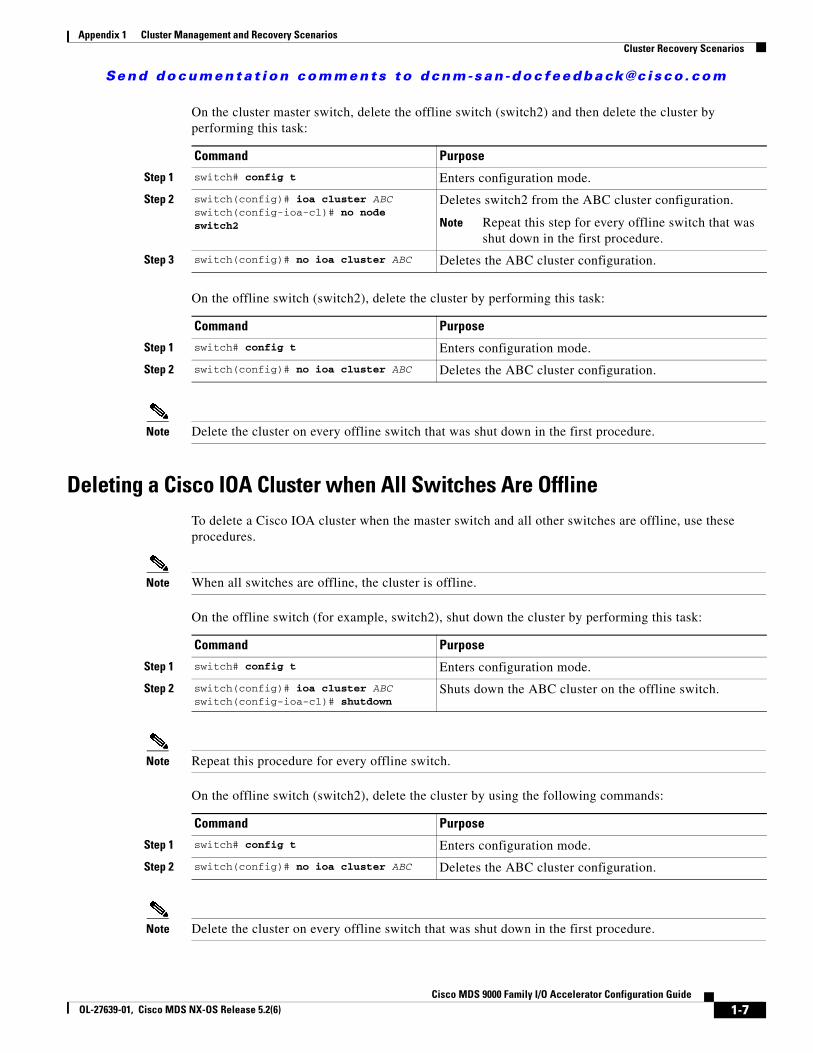
Send documenta t i on comments to dcnm-san -doc feedback@c i sco . com
Appendix 1 Cluster Management and Recovery ScenariosCluster Recovery Scenarios
On the cluster master switch, delete the offline switch (switch2) and then delete the cluster by performing this task:
Command Purpose
Step 1 switch# config t Enters configuration mode.
Step 2 switch(config)# ioa cluster ABC switch(config-ioa-cl)# no node switch2
Deletes switch2 from the ABC cluster configuration.
Note Repeat this step for every offline switch that was shut down in the first procedure.
Step 3 switch(config)# no ioa cluster ABC Deletes the ABC cluster configuration.
On the offline switch (switch2), delete the cluster by performing this task:
Command Purpose
Step 1 switch# config t Enters configuration mode.
Step 2 switch(config)# no ioa cluster ABC Deletes the ABC cluster configuration.
Note Delete the cluster on every offline switch that was shut down in the first procedure.
Deleting a Cisco IOA Cluster when All Switches Are OfflineTo delete a Cisco IOA cluster when the master switch and all other switches are offline, use these procedures.
Note When all switches are offline, the cluster is offline.
On the offline switch (for example, switch2), shut down the cluster by performing this task:
Command Purpose
Step 1 switch# config t Enters configuration mode.
Step 2 switch(config)# ioa cluster ABCswitch(config-ioa-cl)# shutdown
Shuts down the ABC cluster on the offline switch.
Note Repeat this procedure for every offline switch.
On the offline switch (switch2), delete the cluster by using the following commands:
Command Purpose
Step 1 switch# config t Enters configuration mode.
Step 2 switch(config)# no ioa cluster ABC Deletes the ABC cluster configuration.
Note Delete the cluster on every offline switch that was shut down in the first procedure.
1-7Cisco MDS 9000 Family I/O Accelerator Configuration Guide
OL-27639-01, Cisco MDS NX-OS Release 5.2(6)
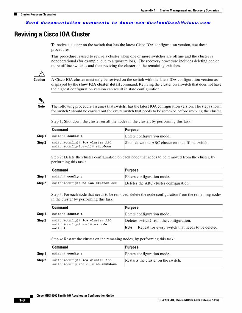
Send documenta t i on comments to dcnm-san -doc feedback@c i sco . com
Appendix 1 Cluster Management and Recovery Scenarios Cluster Recovery Scenarios
Reviving a Cisco IOA ClusterTo revive a cluster on the switch that has the latest Cisco IOA configuration version, use these procedures.
This procedure is used to revive a cluster when one or more switches are offline and the cluster is nonoperational (for example, due to a quorum loss). The recovery procedure includes deleting one or more offline switches and then reviving the cluster on the remaining switches.
Caution A Cisco IOA cluster must only be revived on the switch with the latest IOA configuration version as displayed by the show IOA cluster detail command. Reviving the cluster on a switch that does not have the highest configuration version can result in stale configuration.
Note The following procedure assumes that switch1 has the latest IOA configuration version. The steps shown for switch2 should be carried out for every switch that needs to be removed before reviving the cluster.
Step 1: Shut down the cluster on all the nodes in the cluster, by performing this task:
Command Purpose
Step 1 switch# config t Enters configuration mode.
Step 2 switch(config)# ioa cluster ABCswitch(config-ioa-cl)# shutdown
Shuts down the ABC cluster on the offline switch.
Step 2: Delete the cluster configuration on each node that needs to be removed from the cluster, by performing this task:
Command Purpose
Step 1 switch# config t Enters configuration mode.
Step 2 switch(config)# no ioa cluster ABC Deletes the ABC cluster configuration.
Step 3: For each node that needs to be removed, delete the node configuration from the remaining nodes in the cluster by performing this task:
Command Purpose
Step 1 switch# config t Enters configuration mode.
Step 2 switch(config)# ioa cluster ABCswitch(config-ioa-cl# no node switch2
Deletes switch2 from the configuration.
Note Repeat for every switch that needs to be deleted.
Step 4: Restart the cluster on the remaning nodes, by performing this task:
Command Purpose
Step 1 switch# config t Enters configuration mode.
Step 2 switch(config)# ioa cluster ABCswitch(config-ioa-cl)# no shutdown
Restarts the cluster on the switch.
1-8Cisco MDS 9000 Family I/O Accelerator Configuration Guide
OL-27639-01, Cisco MDS NX-OS Release 5.2(6)