choosing between brush and brushless dc motors between brush and brushless dc motors allied motion...
TRANSCRIPT

Allied Motion Inc. 495 Commerce Drive Amherst, NY 14228 Tel: 1 (716) 242-7535 [email protected] www.alliedmotion.com 1
Choosing Between Brush and Brushless DC Motors
Trade-offs include speed, efficiency, lifetime, maintenance, robustness, size, and cost.
Designing a system that involves motion and performs as intended requires the right motor. Just as the conditions and specifications of motion systems vary from use case to use case, so does the optimal choice of motor. The most fundamental decision involves commutation type: brush or brushless. In some cases, mechanically commutated brush motors provide the best solution for the budget. In other cases, only brushless DC (BLDC) motors will do. Here, we provide a comprehensive review of the technology, along with tips and tricks for choosing the right solution for a given application. Motors 101 An electric motor consists of two basic elements: a rotor and a stator. Both rotor and stator generate a magnetic field, and the interaction between the two fields produces torque that enables the motor to do useful work. Although a wide range of design variations exists, including linear motors, for purposes of this white paper, we will focus on rotary motors in which the rotor (armature) revolves and the stator is fixed.
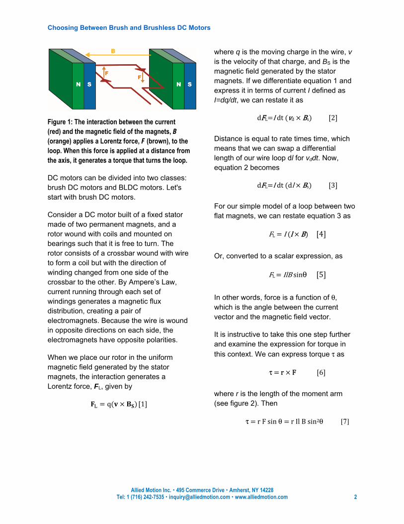
Ampere’s Law tells us that current passing through a wire generates a magnetic field. If we shape that current-carrying wire into a loop and place it in a magnetic field, the interaction between the two fields will apply a turning force, and consequently a torque moment, to the wire (see figure 1). The turning force is known as the Lorenz force. This is the basic principle behind the electric motor.
Choosing Between Brush and Brushless DC Motors
Allied Motion Inc. 495 Commerce Drive Amherst, NY 14228 Tel: 1 (716) 242-7535 [email protected] www.alliedmotion.com 2
Figure 1: The interaction between the current (red) and the magnetic field of the magnets, B (orange) applies a Lorentz force, F (brown), to the loop. When this force is applied at a distance from the axis, it generates a torque that turns the loop.
DC motors can be divided into two classes: brush DC motors and BLDC motors. Let's start with brush DC motors.
Consider a DC motor built of a fixed stator made of two permanent magnets, and a rotor wound with coils and mounted on bearings such that it is free to turn. The rotor consists of a crossbar wound with wire to form a coil but with the direction of winding changed from one side of the crossbar to the other. By Ampere’s Law, current running through each set of windings generates a magnetic flux distribution, creating a pair of electromagnets. Because the wire is wound in opposite directions on each side, the electromagnets have opposite polarities.
When we place our rotor in the uniform magnetic field generated by the stator magnets, the interaction generates a Lorentz force, FL, given by = q( × ) [1]
where q is the moving charge in the wire, v is the velocity of that charge, and BS is the magnetic field generated by the stator magnets. If we differentiate equation 1 and express it in terms of current I defined as I=dq/dt, we can restate it as dFL=I dt (vd × Bs) [2] Distance is equal to rate times time, which means that we can swap a differential length of our wire loop dl for vddt. Now, equation 2 becomes dFL=I dt (dl × Bs) [3] For our simple model of a loop between two flat magnets, we can restate equation 3 as FL = I (l × B) [4] Or, converted to a scalar expression, as FL = IlB sinθ [5] In other words, force is a function of θ, which is the angle between the current vector and the magnetic field vector.
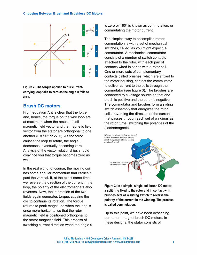
It is instructive to take this one step further and examine the expression for torque in this context. We can express torque τ as
τ = r × F [6] where r is the length of the moment arm (see figure 2). Then τ = r F sin θ = r Il B sin2θ [7]
Choosing Between Brush and Brushless DC Motors
Allied Motion Inc. 495 Commerce Drive Amherst, NY 14228 Tel: 1 (716) 242-7535 [email protected] www.alliedmotion.com 3
Figure 2: The torque applied to our current-carrying loop falls to zero as the angle θ falls to zero.
Brush DC motors From equation 7, it is clear that the force and, hence, the torque on the wire loop are at maximum when the resultant coil magnetic field vector and the magnetic field vector from the stator are orthogonal to one another (θ = 90° or 270°). As the force causes the loop to rotate, the angle θ decreases, eventually becoming zero. Analysis of the vector relationships should convince you that torque becomes zero as well.
In the real world, of course, the moving coil has some angular momentum that carries it past the vertical. If, at the exact same time, we reverse the direction of the current in the loop, the polarity of the electromagnets also reverses. Now, the interaction of the two fields again generates torque, causing the coil to continue its rotation. The torque returns to peak magnitude when the loop is once more horizontal so that the rotor magnetic field is positioned orthogonal to the stator magnetic field. This process of switching current direction when the angle θ
is zero or 180° is known as commutation, or commutating the motor current.
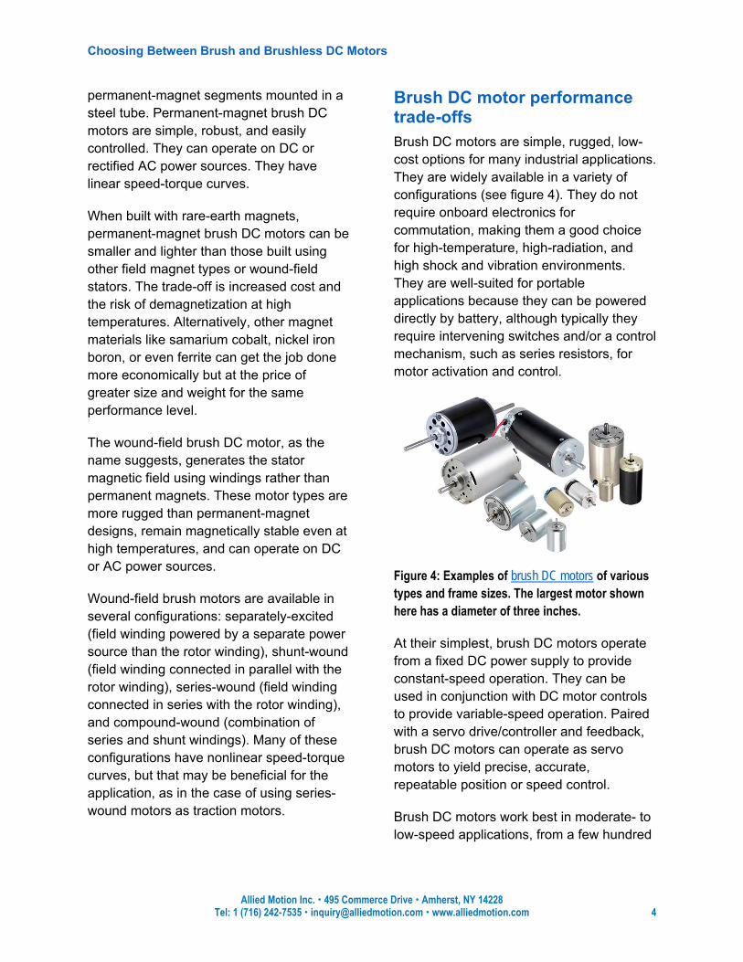
The simplest way to accomplish motor commutation is with a set of mechanical switches, called, as you might expect, a commutator. A mechanical commutator consists of a number of switch contacts attached to the rotor, with each pair of contacts wired in series with a rotor coil. One or more sets of complementary contacts called brushes, which are affixed to the motor housing, contact the commutator to deliver current to the coils through the commutator (see figure 3). The brushes are connected to a voltage source so that one brush is positive and the other is negative. The commutator and brushes form a sliding switch assembly that energizes the rotor coils, reversing the direction of the current that passes through each set of windings as the rotor turns, switching the polarities of the electromagnets.
Figure 3: In a simple, single-coil brush DC motor, a split ring fixed to the rotor and in contact with brushes acts as a sliding switch to reverse the polarity of the current in the winding. The process is called commutation.
Up to this point, we have been describing permanent-magnet brush DC motors. In these designs, the stator consists of
Choosing Between Brush and Brushless DC Motors
Allied Motion Inc. 495 Commerce Drive Amherst, NY 14228 Tel: 1 (716) 242-7535 [email protected] www.alliedmotion.com 4
permanent-magnet segments mounted in a steel tube. Permanent-magnet brush DC motors are simple, robust, and easily controlled. They can operate on DC or rectified AC power sources. They have linear speed-torque curves.
When built with rare-earth magnets, permanent-magnet brush DC motors can be smaller and lighter than those built using other field magnet types or wound-field stators. The trade-off is increased cost and the risk of demagnetization at high temperatures. Alternatively, other magnet materials like samarium cobalt, nickel iron boron, or even ferrite can get the job done more economically but at the price of greater size and weight for the same performance level.
The wound-field brush DC motor, as the name suggests, generates the stator magnetic field using windings rather than permanent magnets. These motor types are more rugged than permanent-magnet designs, remain magnetically stable even at high temperatures, and can operate on DC or AC power sources.
Wound-field brush motors are available in several configurations: separately-excited (field winding powered by a separate power source than the rotor winding), shunt-wound (field winding connected in parallel with the rotor winding), series-wound (field winding connected in series with the rotor winding), and compound-wound (combination of series and shunt windings). Many of these configurations have nonlinear speed-torque curves, but that may be beneficial for the application, as in the case of using series-wound motors as traction motors.
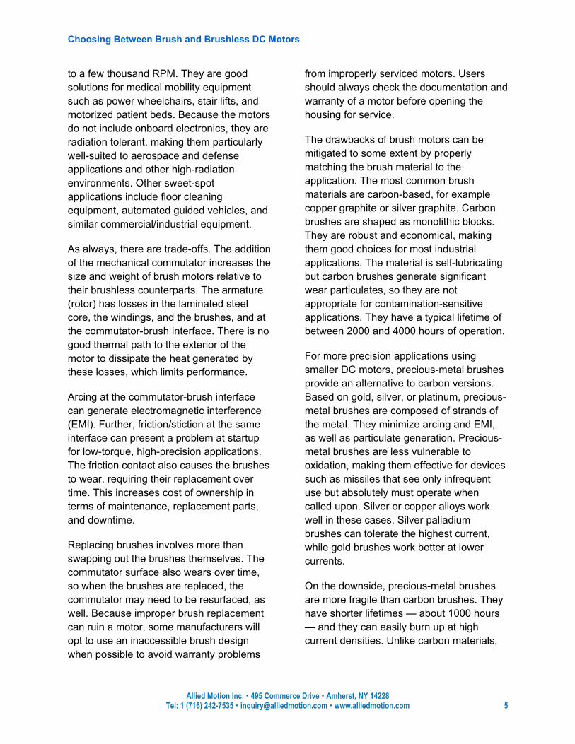
Brush DC motor performance trade-offs Brush DC motors are simple, rugged, low-cost options for many industrial applications. They are widely available in a variety of configurations (see figure 4). They do not require onboard electronics for commutation, making them a good choice for high-temperature, high-radiation, and high shock and vibration environments. They are well-suited for portable applications because they can be powered directly by battery, although typically they require intervening switches and/or a control mechanism, such as series resistors, for motor activation and control.
Figure 4: Examples of brush DC motors of various types and frame sizes. The largest motor shown here has a diameter of three inches.
At their simplest, brush DC motors operate from a fixed DC power supply to provide constant-speed operation. They can be used in conjunction with DC motor controls to provide variable-speed operation. Paired with a servo drive/controller and feedback, brush DC motors can operate as servo motors to yield precise, accurate, repeatable position or speed control.
Brush DC motors work best in moderate- to low-speed applications, from a few hundred
Choosing Between Brush and Brushless DC Motors
Allied Motion Inc. 495 Commerce Drive Amherst, NY 14228 Tel: 1 (716) 242-7535 [email protected] www.alliedmotion.com 5
to a few thousand RPM. They are good solutions for medical mobility equipment such as power wheelchairs, stair lifts, and motorized patient beds. Because the motors do not include onboard electronics, they are radiation tolerant, making them particularly well-suited to aerospace and defense applications and other high-radiation environments. Other sweet-spot applications include floor cleaning equipment, automated guided vehicles, and similar commercial/industrial equipment.
As always, there are trade-offs. The addition of the mechanical commutator increases the size and weight of brush motors relative to their brushless counterparts. The armature (rotor) has losses in the laminated steel core, the windings, and the brushes, and at the commutator-brush interface. There is no good thermal path to the exterior of the motor to dissipate the heat generated by these losses, which limits performance.
Arcing at the commutator-brush interface can generate electromagnetic interference (EMI). Further, friction/stiction at the same interface can present a problem at startup for low-torque, high-precision applications. The friction contact also causes the brushes to wear, requiring their replacement over time. This increases cost of ownership in terms of maintenance, replacement parts, and downtime.
Replacing brushes involves more than swapping out the brushes themselves. The commutator surface also wears over time, so when the brushes are replaced, the commutator may need to be resurfaced, as well. Because improper brush replacement can ruin a motor, some manufacturers will opt to use an inaccessible brush design when possible to avoid warranty problems
from improperly serviced motors. Users should always check the documentation and warranty of a motor before opening the housing for service.
The drawbacks of brush motors can be mitigated to some extent by properly matching the brush material to the application. The most common brush materials are carbon-based, for example copper graphite or silver graphite. Carbon brushes are shaped as monolithic blocks. They are robust and economical, making them good choices for most industrial applications. The material is self-lubricating but carbon brushes generate significant wear particulates, so they are not appropriate for contamination-sensitive applications. They have a typical lifetime of between 2000 and 4000 hours of operation.
For more precision applications using smaller DC motors, precious-metal brushes provide an alternative to carbon versions. Based on gold, silver, or platinum, precious-metal brushes are composed of strands of the metal. They minimize arcing and EMI, as well as particulate generation. Precious-metal brushes are less vulnerable to oxidation, making them effective for devices such as missiles that see only infrequent use but absolutely must operate when called upon. Silver or copper alloys work well in these cases. Silver palladium brushes can tolerate the highest current, while gold brushes work better at lower currents.
On the downside, precious-metal brushes are more fragile than carbon brushes. They have shorter lifetimes — about 1000 hours — and they can easily burn up at high current densities. Unlike carbon materials,
Choosing Between Brush and Brushless DC Motors
Allied Motion Inc. 495 Commerce Drive Amherst, NY 14228 Tel: 1 (716) 242-7535 [email protected] www.alliedmotion.com 6
they are not self-lubricating. Because precious-metal brushes are also more expensive than their carbon counterparts, they have a higher total cost of ownership.
Brushless DC (BLDC) motors BLDC motors provide an alternative to brushed designs. In the brushless version of our rotary DC motor, the windings are on the stator and the magnets are on the rotor (see figure 5). Because the windings are fixed, direct electrical connections can be made to them easily. As a result, there is no need for a mechanical commutator and brushes.
Figure 5: In a BLDC motor, the magnets (blue and green) are on the rotor and the windings (copper) are on the stator. This improves heat transfer, thereby enabling higher performance than brush motors of equivalent size. The motor shown in this diagram uses Hall-effect sensors to determine rotor position.
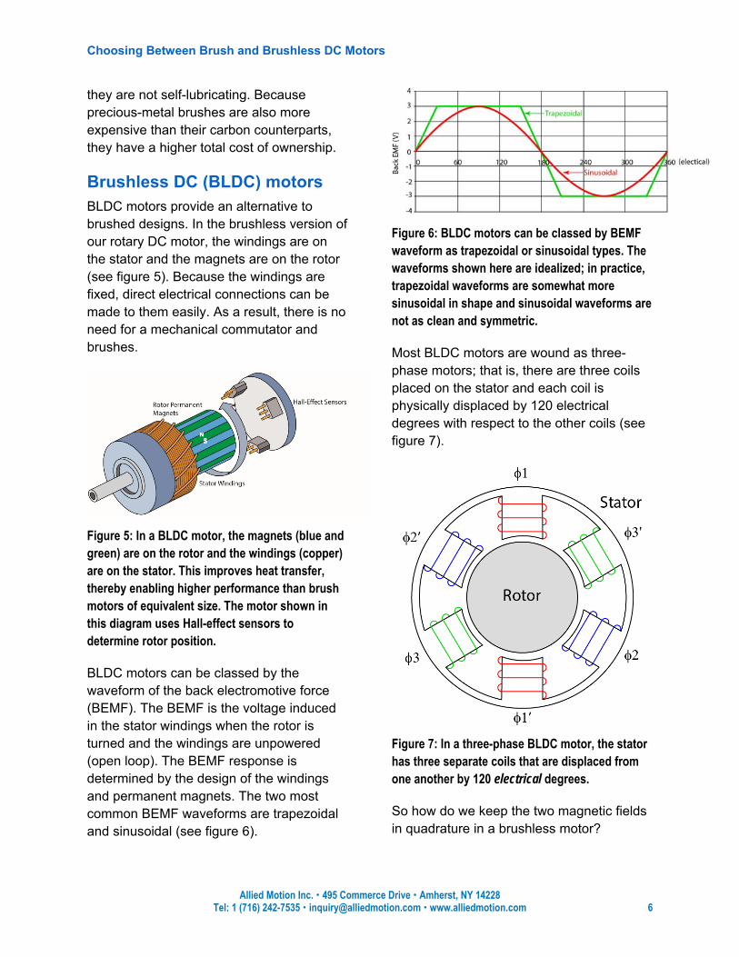
BLDC motors can be classed by the waveform of the back electromotive force (BEMF). The BEMF is the voltage induced in the stator windings when the rotor is turned and the windings are unpowered (open loop). The BEMF response is determined by the design of the windings and permanent magnets. The two most common BEMF waveforms are trapezoidal and sinusoidal (see figure 6).
Figure 6: BLDC motors can be classed by BEMF waveform as trapezoidal or sinusoidal types. The waveforms shown here are idealized; in practice, trapezoidal waveforms are somewhat more sinusoidal in shape and sinusoidal waveforms are not as clean and symmetric.
Most BLDC motors are wound as three-phase motors; that is, there are three coils placed on the stator and each coil is physically displaced by 120 electrical degrees with respect to the other coils (see figure 7).
Figure 7: In a three-phase BLDC motor, the stator has three separate coils that are displaced from one another by 120 electrical degrees.
So how do we keep the two magnetic fields in quadrature in a brushless motor?
Choosing Between Brush and Brushless DC Motors
Allied Motion Inc. 495 Commerce Drive Amherst, NY 14228 Tel: 1 (716) 242-7535 [email protected] www.alliedmotion.com 7
Somehow, the system needs to detect (or estimate) the angular position of the rotor magnet field. With that information, it is then possible to control the stator winding currents in the three phase coils in such a way that the stator field is kept in quadrature with respect to the rotor field under all expected operating conditions.
Once the BLDC motor type is selected, then, it is necessary to choose a feedback approach to determine rotor position, which the drive will then use to generate the commutation signal that keeps the motor turning. Feedback technologies include BEMF sensing, Hall-effect sensors, sensorless vector control, and closed-loop feedback using encoders or resolvers. Commutation types include six-step and sinusoidal. In theory, all of these technologies can be mixed and matched with trapezoidal and sinusoidal motors. In reality, there are certain combinations that work well for different applications. Let’s consider each motor type in detail.
Commutation and control of trapezoidal BLDC Motors Trapezoidal motors provide good performance for fixed-speed applications or applications requiring only moderate position or speed resolution. The simplest control scheme used with them is open-loop control using BEMF sensing to monitor rotor position. This kind of “sensorless” motor control is not as robust in its performance as sensored motor control; it offers only limited speed range and load-regulation capabilities.
BLDC motors using BEMF rotor position sensing are ideal for applications that do not require high starting torque or good
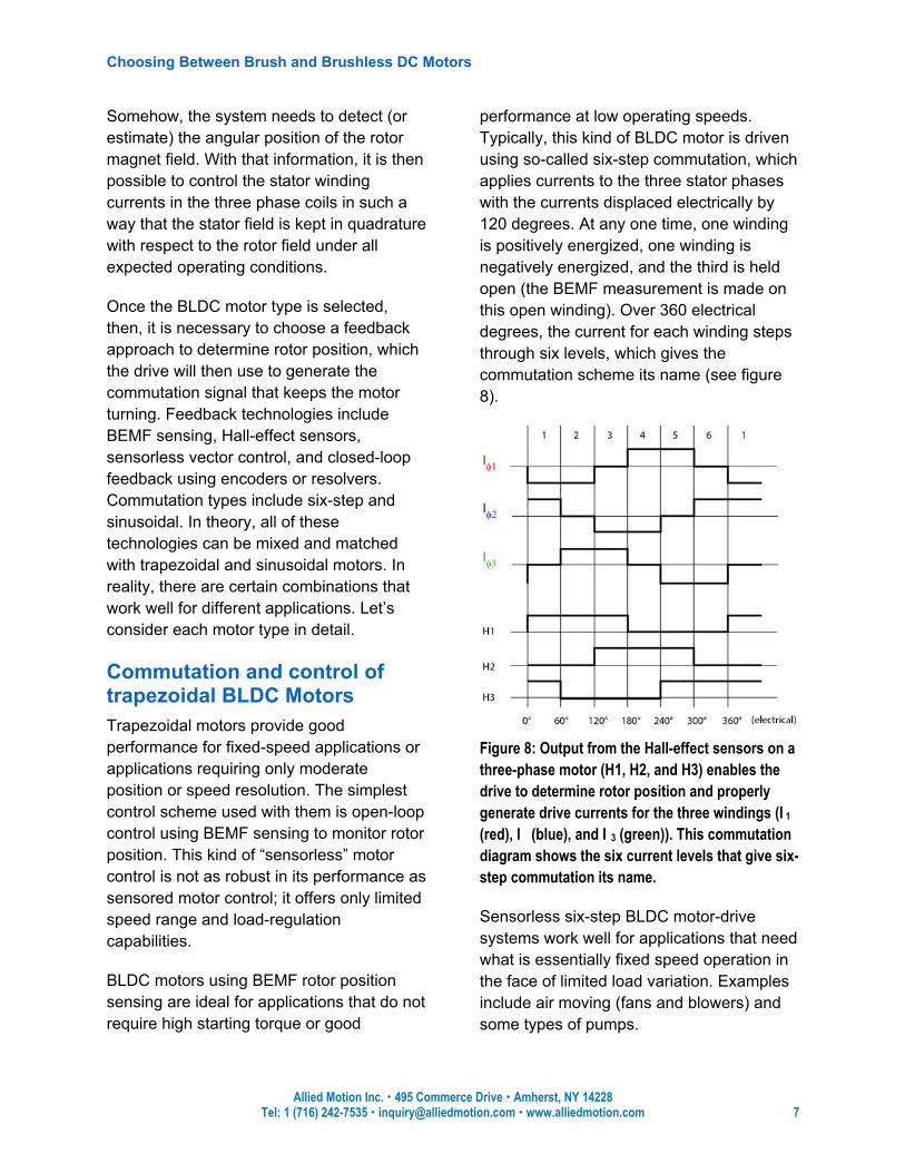
performance at low operating speeds. Typically, this kind of BLDC motor is driven using so-called six-step commutation, which applies currents to the three stator phases with the currents displaced electrically by 120 degrees. At any one time, one winding is positively energized, one winding is negatively energized, and the third is held open (the BEMF measurement is made on this open winding). Over 360 electrical degrees, the current for each winding steps through six levels, which gives the commutation scheme its name (see figure 8).
Figure 8: Output from the Hall-effect sensors on a three-phase motor (H1, H2, and H3) enables the drive to determine rotor position and properly generate drive currents for the three windings (I�1 (red), I��� (blue), and I��3 (green)). This commutation diagram shows the six current levels that give six-step commutation its name.
Sensorless six-step BLDC motor-drive systems work well for applications that need what is essentially fixed speed operation in the face of limited load variation. Examples include air moving (fans and blowers) and some types of pumps.
Choosing Between Brush and Brushless DC Motors
Allied Motion Inc. 495 Commerce Drive Amherst, NY 14228 Tel: 1 (716) 242-7535 [email protected] www.alliedmotion.com 8
The next level up for trapezoidal motors in terms of performance is closed-loop control with Hall-effect sensors (see figure 5). Placed 120 electrical degrees apart (or 60°, when appropriate), these magnetic sensors indicate the position of the rotor magnets and, therefore, the rotor. The motor fields remain essentially in quadrature and, most important, the motor runs as commanded with good starting torque and low-speed operating characteristics. Hall-effect sensors provide more accurate rotor position sensing compared to sensorless BLDC motor systems, but the approach increases the cost and complexity of the system.
An alternative to both sensorless open-loop and sensored closed-loop commutation control is sensorless vector control (see figure 9). This patented technology enables detection of rotor position even at standstill. The approach is based on algorithms that apply motor phase inductance measurements to enable reliable startup under load.
Figure 9: BLDC motors operated with sensorless vector control applied by drives like the DPFlex™ nearly match the performance of closed-loop feedback devices while offering reduced cost, complexity, and size.
Sensorless vector control delivers performance very nearly as good as that of
closed-loop commutation but without the additional cost, size, and complexity introduced by the addition of an encoder or resolver. Applications include pumps, high-speed compressors, medical hand pieces, respirators, centrifuges, and high-speed conveyors.
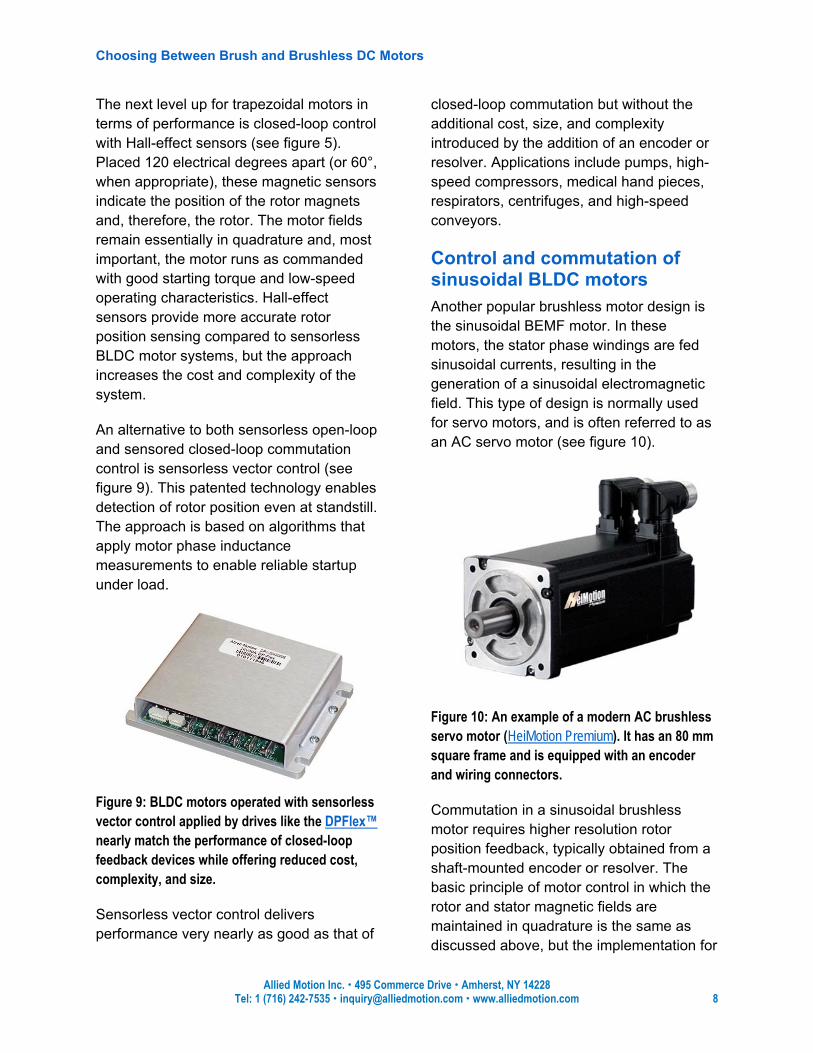
Control and commutation of sinusoidal BLDC motors Another popular brushless motor design is the sinusoidal BEMF motor. In these motors, the stator phase windings are fed sinusoidal currents, resulting in the generation of a sinusoidal electromagnetic field. This type of design is normally used for servo motors, and is often referred to as an AC servo motor (see figure 10).
Figure 10: An example of a modern AC brushless servo motor (HeiMotion Premium). It has an 80 mm square frame and is equipped with an encoder and wiring connectors.
Commutation in a sinusoidal brushless motor requires higher resolution rotor position feedback, typically obtained from a shaft-mounted encoder or resolver. The basic principle of motor control in which the rotor and stator magnetic fields are maintained in quadrature is the same as discussed above, but the implementation for
Choosing Between Brush and Brushless DC Motors
Allied Motion Inc. 495 Commerce Drive Amherst, NY 14228 Tel: 1 (716) 242-7535 [email protected] www.alliedmotion.com 9
AC servo motors is more complex than for a brush or trapezoidal BLDC device.
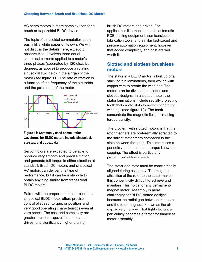
The topic of sinusoidal commutation could easily fill a white paper of its own. We will not discuss the details here, except to observe that it involves three equal sinusoidal currents applied to a motor’s three phases (separated by 120 electrical degrees, as above) to produce a rotating sinusoidal flux (field) in the air gap of the motor (see figure 11). The rate of rotation is a function of the frequency of the sinusoids and the pole count of the motor.
Figure 11: Commonly used commutation waveforms for BLDC motors include sinusoidal, six-step, and trapezoidal.
Servo motors are expected to be able to produce very smooth and precise motion, and generate full torque in either direction at standstill. Brush DC motors and sinusoidal AC motors can deliver this type of performance, but it can be a struggle to obtain anything similar from trapezoidal BLDC motors.
Paired with the proper motor controller, the sinusoidal BLDC motor offers precise control of speed, torque, or position, and very good operating characteristics even at zero speed. The cost and complexity are greater than for trapezoidal motors and drives, and significantly higher than for
brush DC motors and drives. For applications like machine tools, automatic PCB stuffing equipment, semiconductor fabrication tools, and similar fast-paced and precise automation equipment, however, that added complexity and cost are well worth it.
Slotted and slotless brushless motors The stator in a BLDC motor is built up of a stack of thin laminations, then wound with copper wire to create the windings. The motors can be divided into slotted and slotless designs. In a slotted motor, the stator laminations include radially projecting teeth that create slots to accommodate the windings (see figure 12). The teeth concentrate the magnetic field, increasing torque density.
The problem with slotted motors is that the rotor magnets are preferentially attracted to the salient stator teeth compared to the slots between the teeth. This introduces a periodic variation in motor torque known as cogging. The effect is particularly pronounced at low speeds.
The stator and rotor must be concentrically aligned during assembly. The magnetic attraction of the rotor to the stator makes this concentricity difficult to achieve and maintain. This holds for any permanent-magnet motor. Assembly is more challenging for BLDC slotted designs because the radial gap between the teeth and the rotor magnets, known as the air gap, is very narrow. That tight clearance particularly becomes a factor for frameless motor assembly.
Choosing Between Brush and Brushless DC Motors
Allied Motion Inc. 495 Commerce Drive Amherst, NY 14228 Tel: 1 (716) 242-7535 [email protected] www.alliedmotion.com 10
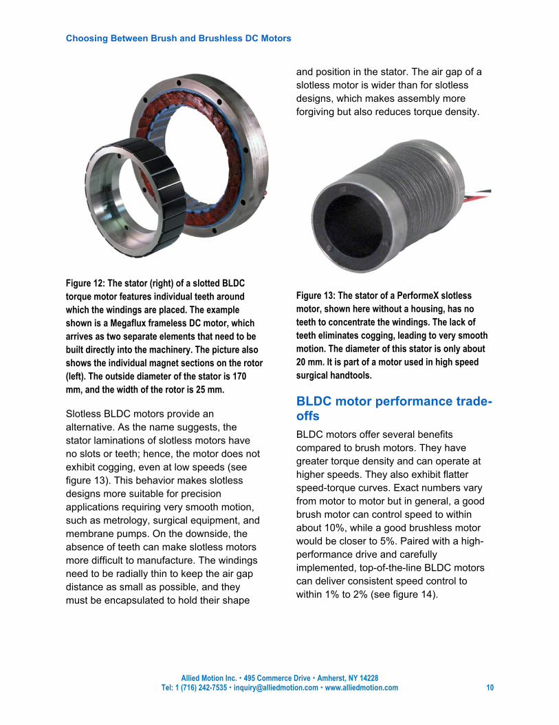
Figure 12: The stator (right) of a slotted BLDC torque motor features individual teeth around which the windings are placed. The example shown is a Megaflux frameless DC motor, which arrives as two separate elements that need to be built directly into the machinery. The picture also shows the individual magnet sections on the rotor (left). The outside diameter of the stator is 170 mm, and the width of the rotor is 25 mm.
Slotless BLDC motors provide an alternative. As the name suggests, the stator laminations of slotless motors have no slots or teeth; hence, the motor does not exhibit cogging, even at low speeds (see figure 13). This behavior makes slotless designs more suitable for precision applications requiring very smooth motion, such as metrology, surgical equipment, and membrane pumps. On the downside, the absence of teeth can make slotless motors more difficult to manufacture. The windings need to be radially thin to keep the air gap distance as small as possible, and they must be encapsulated to hold their shape
and position in the stator. The air gap of a slotless motor is wider than for slotless designs, which makes assembly more forgiving but also reduces torque density.
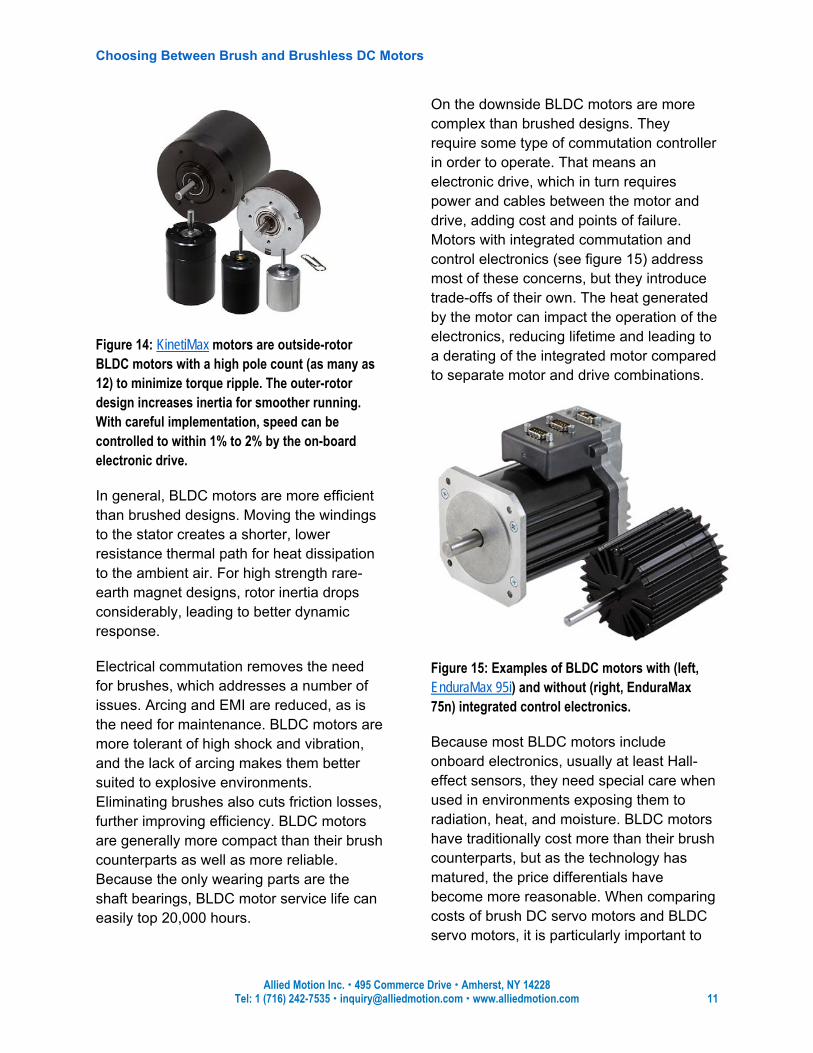
Figure 13: The stator of a PerformeX slotless motor, shown here without a housing, has no teeth to concentrate the windings. The lack of teeth eliminates cogging, leading to very smooth motion. The diameter of this stator is only about 20 mm. It is part of a motor used in high speed surgical handtools.
BLDC motor performance trade-offs BLDC motors offer several benefits compared to brush motors. They have greater torque density and can operate at higher speeds. They also exhibit flatter speed-torque curves. Exact numbers vary from motor to motor but in general, a good brush motor can control speed to within about 10%, while a good brushless motor would be closer to 5%. Paired with a high-performance drive and carefully implemented, top-of-the-line BLDC motors can deliver consistent speed control to within 1% to 2% (see figure 14).
Choosing Between Brush and Brushless DC Motors
Allied Motion Inc. 495 Commerce Drive Amherst, NY 14228 Tel: 1 (716) 242-7535 [email protected] www.alliedmotion.com 11
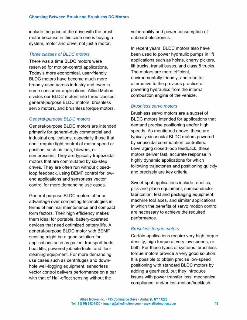
Figure 14: KinetiMax motors are outside-rotor BLDC motors with a high pole count (as many as 12) to minimize torque ripple. The outer-rotor design increases inertia for smoother running. With careful implementation, speed can be controlled to within 1% to 2% by the on-board electronic drive.
In general, BLDC motors are more efficient than brushed designs. Moving the windings to the stator creates a shorter, lower resistance thermal path for heat dissipation to the ambient air. For high strength rare-earth magnet designs, rotor inertia drops considerably, leading to better dynamic response.
Electrical commutation removes the need for brushes, which addresses a number of issues. Arcing and EMI are reduced, as is the need for maintenance. BLDC motors are more tolerant of high shock and vibration, and the lack of arcing makes them better suited to explosive environments. Eliminating brushes also cuts friction losses, further improving efficiency. BLDC motors are generally more compact than their brush counterparts as well as more reliable. Because the only wearing parts are the shaft bearings, BLDC motor service life can easily top 20,000 hours.
On the downside BLDC motors are more complex than brushed designs. They require some type of commutation controller in order to operate. That means an electronic drive, which in turn requires power and cables between the motor and drive, adding cost and points of failure. Motors with integrated commutation and control electronics (see figure 15) address most of these concerns, but they introduce trade-offs of their own. The heat generated by the motor can impact the operation of the electronics, reducing lifetime and leading to a derating of the integrated motor compared to separate motor and drive combinations.
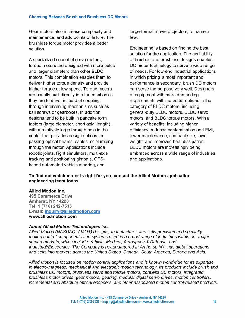
Figure 15: Examples of BLDC motors with (left, EnduraMax 95i) and without (right, EnduraMax 75n) integrated control electronics.
Because most BLDC motors include onboard electronics, usually at least Hall-effect sensors, they need special care when used in environments exposing them to radiation, heat, and moisture. BLDC motors have traditionally cost more than their brush counterparts, but as the technology has matured, the price differentials have become more reasonable. When comparing costs of brush DC servo motors and BLDC servo motors, it is particularly important to
Choosing Between Brush and Brushless DC Motors
Allied Motion Inc. 495 Commerce Drive Amherst, NY 14228 Tel: 1 (716) 242-7535 [email protected] www.alliedmotion.com 12
include the price of the drive with the brush motor because in this case one is buying a system, motor and drive, not just a motor.
Three classes of BLDC motors There was a time BLDC motors were reserved for motion-control applications. Today’s more economical, user-friendly BLDC motors have become much more broadly used across industry and even in some consumer applications. Allied Motion divides our BLDC motors into three classes: general-purpose BLDC motors, brushless servo motors, and brushless torque motors.
General-purpose BLDC motors General-purpose BLDC motors are intended primarily for general-duty commercial and industrial applications, especially those that don’t require tight control of motor speed or position, such as fans, blowers, or compressors. They are typically trapezoidal motors that are commutated by six-step drives. They are often run without closed-loop feedback, using BEMF control for low-end applications and sensorless vector control for more demanding use cases.
General-purpose BLDC motors offer an advantage over competing technologies in terms of minimal maintenance and compact form factors. Their high efficiency makes them ideal for portable, battery-operated devices that need optimized battery life. A general-purpose BLDC motor with BEMF sensing might be a good solution for applications such as patient transport beds, boat lifts, powered job-site tools, and floor cleaning equipment. For more demanding use cases such as centrifuges and down-hole well-logging equipment, sensorless vector control delivers performance on a par with that of Hall-effect sensing without the
vulnerability and power consumption of onboard electronics.
In recent years, BLDC motors also have been used to power hydraulic pumps in lift applications such as hoists, cherry pickers, lift trucks, transit buses, and class 8 trucks. The motors are more efficient, environmentally friendly, and a better alternative to the previous practice of powering hydraulics from the internal combustion engine of the vehicle.
Brushless servo motors Brushless servo motors are a subset of BLDC motors intended for applications that demand precise positioning and/or high speeds. As mentioned above, these are typically sinusoidal BLDC motors powered by sinusoidal commutation controllers. Leveraging closed-loop feedback, these motors deliver fast, accurate response in highly dynamic applications for which following trajectories and positioning quickly and precisely are key criteria.
Sweet-spot applications include robotics, pick-and-place equipment, semiconductor fabrication, test and packaging equipment, machine tool axes, and similar applications in which the benefits of servo motion control are necessary to achieve the required performance.
Brushless torque motors Certain applications require very high torque density, high torque at very low speeds, or both. For these types of systems, brushless torque motors provide a very good solution. It is possible to obtain precise low-speed positioning with standard BLDC motors by adding a gearhead, but they introduce issues with power transfer loss, mechanical compliance, and/or lost-motion/backlash.
Choosing Between Brush and Brushless DC Motors
Allied Motion Inc. 495 Commerce Drive Amherst, NY 14228 Tel: 1 (716) 242-7535 [email protected] www.alliedmotion.com 13
Gear motors also increase complexity and maintenance, and add points of failure. The brushless torque motor provides a better solution.
A specialized subset of servo motors, torque motors are designed with more poles and larger diameters than other BLDC motors. This combination enables them to deliver higher torque density and provide higher torque at low speed. Torque motors are usually built directly into the mechanics they are to drive, instead of coupling through intervening mechanisms such as ball screws or gearboxes. In addition, designs tend to be built in pancake form factors (large diameter, short axial length), with a relatively large through hole in the center that provides design options for passing optical beams, cables, or plumbing through the motor. Applications include robotic joints, flight simulators, multi-axis tracking and positioning gimbals, GPS-based automated vehicle steering, and
large-format movie projectors, to name a few.
Engineering is based on finding the best solution for the application. The availability of brushed and brushless designs enables DC motor technology to serve a wide range of needs. For low-end industrial applications in which pricing is most important and performance is secondary, brush DC motors can serve the purpose very well. Designers of equipment with more demanding requirements will find better options in the category of BLDC motors, including general-duty BLDC motors, BLDC servo motors, and BLDC torque motors. With a variety of benefits, including higher efficiency, reduced contamination and EMI, lower maintenance, compact size, lower weight, and improved heat dissipation, BLDC motors are increasingly being embraced across a wide range of industries and applications.
To find out which motor is right for you, contact the Allied Motion application engineering team today. Allied Motion Inc. 495 Commerce Drive Amherst, NY 14228 Tel: 1 (716) 242-7535 E-mail: [email protected] www.alliedmotion.com About Allied Motion Technologies Inc. Allied Motion (NASDAQ: AMOT) designs, manufactures and sells precision and specialty motion control components and systems used in a broad range of industries within our major served markets, which include Vehicle, Medical, Aerospace & Defense, and Industrial/Electronics. The Company is headquartered in Amherst, NY, has global operations and sells into markets across the United States, Canada, South America, Europe and Asia. Allied Motion is focused on motion control applications and is known worldwide for its expertise in electro-magnetic, mechanical and electronic motion technology. Its products include brush and brushless DC motors, brushless servo and torque motors, coreless DC motors, integrated brushless motor-drives, gear motors, gearing, modular digital servo drives, motion controllers, incremental and absolute optical encoders, and other associated motion control-related products.