chillers technical data - duoelektronik toplotna pumpa voda-voda.pdf · technical data chillers...
TRANSCRIPT

EWWP-KBW1NEWLP-KBW1N
Technical DataChillers
W a t e r C o o l e d C h i l l e r
E C D E N 1 0 - 4 1 1 A
ECDEN10-411_EWWP-EWLP-KBW1N.pdf 1 10/19/2010 9:38:25 AM
EWWP-KBW1NEWLP-KBW1N
Technical DataChillers
W a t e r C o o l e d C h i l l e r
E C D E N 1 0 - 4 1 1 A
ECDEN10-411_EWWP-EWLP-KBW1N.pdf 2 10/19/2010 9:38:34 AM
• Hydronic Systems • Single Unit 1
• Single Unit • Water cooled chiller • EWWP-KBW1N
TABLE OF CONTENTSEWWP-KBW1N
1 Features . . . . . . . . . . . . . . . . . . . . . . . . . . . . . . . . . . . . . . . . . . . . . . . . . . . . . . . . . . . . . 2
2 Specifications . . . . . . . . . . . . . . . . . . . . . . . . . . . . . . . . . . . . . . . . . . . . . . . . . . . . . . . 3Technical Specifications . . . . . . . . . . . . . . . . . . . . . . . . . . . . . . . . . . . . . . . . . . . . . 3Technical Specifications . . . . . . . . . . . . . . . . . . . . . . . . . . . . . . . . . . . . . . . . . . . . . 4Electrical Specifications . . . . . . . . . . . . . . . . . . . . . . . . . . . . . . . . . . . . . . . . . . . . . . 5Electrical Specifications . . . . . . . . . . . . . . . . . . . . . . . . . . . . . . . . . . . . . . . . . . . . . . 5
3 Options . . . . . . . . . . . . . . . . . . . . . . . . . . . . . . . . . . . . . . . . . . . . . . . . . . . . . . . . . . . . . . 6Options . . . . . . . . . . . . . . . . . . . . . . . . . . . . . . . . . . . . . . . . . . . . . . . . . . . . . . . . . . . . . . . 6
4 Capacity tables . . . . . . . . . . . . . . . . . . . . . . . . . . . . . . . . . . . . . . . . . . . . . . . . . . . . . 7Cooling/Heating Capacity Tables . . . . . . . . . . . . . . . . . . . . . . . . . . . . . . . . . . . . 7Capacity Correction Factor . . . . . . . . . . . . . . . . . . . . . . . . . . . . . . . . . . . . . . . . . . 11
5 Dimensional drawings . . . . . . . . . . . . . . . . . . . . . . . . . . . . . . . . . . . . . . . . . . . . 12Dimensional Drawings . . . . . . . . . . . . . . . . . . . . . . . . . . . . . . . . . . . . . . . . . . . . . . 12
6 Centre of gravity . . . . . . . . . . . . . . . . . . . . . . . . . . . . . . . . . . . . . . . . . . . . . . . . . . . 16Centre of Gravity . . . . . . . . . . . . . . . . . . . . . . . . . . . . . . . . . . . . . . . . . . . . . . . . . . . . 16
7 Piping diagrams . . . . . . . . . . . . . . . . . . . . . . . . . . . . . . . . . . . . . . . . . . . . . . . . . . . 18Piping Diagrams . . . . . . . . . . . . . . . . . . . . . . . . . . . . . . . . . . . . . . . . . . . . . . . . . . . . 18
8 Wiring diagrams . . . . . . . . . . . . . . . . . . . . . . . . . . . . . . . . . . . . . . . . . . . . . . . . . . . 22Wiring Diagrams - Three Phase . . . . . . . . . . . . . . . . . . . . . . . . . . . . . . . . . . . . 22
9 Sound data . . . . . . . . . . . . . . . . . . . . . . . . . . . . . . . . . . . . . . . . . . . . . . . . . . . . . . . . . 23Sound Power Spectrum . . . . . . . . . . . . . . . . . . . . . . . . . . . . . . . . . . . . . . . . . . . . . 23
10 Operation range . . . . . . . . . . . . . . . . . . . . . . . . . . . . . . . . . . . . . . . . . . . . . . . . . . . 26Operation Range . . . . . . . . . . . . . . . . . . . . . . . . . . . . . . . . . . . . . . . . . . . . . . . . . . . . 26
11 Hydraulic performance. . . . . . . . . . . . . . . . . . . . . . . . . . . . . . . . . . . . . . . . . . . . 28Water Pressure Drop Curve Evaporator/Condenser . . . . . . . . . . . . . . . . 28
ECDEN10-411_EWWP-EWLP-KBW1N.pdf 3 10/19/2010 9:38:36 AM

• Single Unit • Water cooled chiller • EWWP-KBW1N
• Hydronic Systems • Single Unit2
1 Features
11
Single Unit Hydronic Sys EWWP-KBW1N Water coole • Standard integrated: main switch, water filter, flow switch, air purge, pressure ports
• Daikin scroll compressor
• Optimised for use with R-407C
• Electronic DDC controller
• Low operating sound level
• Low energy consumption
• Extension possible up to 72HP
• Compact dimensions and low refrigerant volume
• Easy installation and maintenance
• Stainless steel plate heat exchanger
• Remote cooling or heating selection
• Water/water heat pump, with water reversibility
• Compatible with hydraulic module
ECDEN10-411_EWWP-EWLP-KBW1N.pdf 4 10/19/2010 9:38:36 AM

• Hydronic Systems • Single Unit 3
• Single Unit • Water cooled chiller • EWWP-KBW1N
2 Specifications
12
2-1 Technical SpecificationsEWWP014
KBW1NEWWP022
KBW1NEWWP028
KBW1NEWWP035
KBW1NEWWP045
KBW1NEWWP055
KBW1NEWWP065
KBW1NEWWP090
KBW1NEWWP100
KBW1NEWWP110
KBW1N
Cooling capacity Nom. kW 13.0 21.5 28.0 32.5 43.0 56.0 65.0 86.0 99.0 112 Heating capacity Nom. kW 16.6 27.3 35.4 41.2 54.8 71.4 82.7 110 126 143Capacity steps number 1 2 4Power input Cooling Nom. kW 3.61 5.79 7.48 8.75 11.80 15.50 17.60 23.6 27.3 31.0Casing Colour Ivory white (Munsell code: 5Y7.5/1)
Material Polyester painted steel plateDimensions Unit Height mm 600 1,200
Width mm 600Depth mm 600 1,200
Weight Unit kg 118 155 165 172 300 320 334 600 620 640Water heat exchanger - evaporator
Type Brazed plateMinimum water volume in the system l 62 103 134 155 205 268 311 205 268Water flow rate Min. l/min 19 31 40 47 62 80 93 123 142 161
Nom. l/min 37 62 80 93 123 161 186 247 284 321Max. l/min 75 123 161 186 247 321 373 493 568 642
Insulation material Polyethylene foamModel Quantity 1 2
Water heat exchanger - condenser
Type Brazed plateWater flow rate Min. l/min 24 39 51 59 79 102 118 157 181 205
Nom. l/min 48 78 102 118 157 205 237 314 362 410Max. l/min 95 157 203 237 314 410 474 629 724 819
Model Quantity 1 2Sound power level Cooling Nom. dBA 64 71 67 74 71Compressor Type Hermetically sealed scroll compressor
Quantity 1 2 4 2 4Model JT140B
F-YEJT212D
A-YEJT300D
A-YEJT335D
A-YEJT212D
A-YEJT300D
A-YEJT335D
A-YEJT212DA-YE JT300D
A-YESpeed rpm 2,900Oil Charged volume l 1.5 2.7
Compressor 2 Quantity - 2 -Model - JT300D
A-YE-
Speed rpm - 2,900 -Oil Charged volume l - 2.7 -
Refrigerant Type R-407CCharge kg 1.2 2 2.5 3.1 4.6 5.6 -Control Thermostatic expansion valveCircuits Quantity 1 2 4
Refrigerant circuit Charge kg - 9.2Refrigerant oil Type FVC68DPiping connections Evaporator water inlet/outlet FBSP 25mm FBSP 40mm 2 x 2 x FBSP 38mm
Evaporator water drain Field installationCondenser water inlet/outlet FBSP 25mm FBSP 40mm 2 x 2 x FBSP 38mmCondenser water drain Field installation
ECDEN10-411_EWWP-EWLP-KBW1N.pdf 5 10/19/2010 9:38:36 AM

• Single Unit • Water cooled chiller • EWWP-KBW1N
• Hydronic Systems • Single Unit4
2 Specifications
12
2-2 Technical SpecificationsEWWP120
KBW1NEWWP130
KBW1NEWWP145
KBW1NEWWP155
KBW1NEWWP165
KBW1NEWWP175
KBW1NEWWP185
KBW1NEWWP195
KBW1N
Cooling capacity Nom. kW 121 130 142 155 168 177 186 195 Heating capacity Nom. kW 154 165 181 198 214 226 237 248Capacity steps number 4 6Power input Cooling Nom. kW 33.1 35.2 39.1 42.8 46.5 48.6 50.7 52.8Casing Colour Ivory white (Munsell code: 5Y7.5/1)
Material Polyester painted steel plateDimensions Unit Height mm 1,200 1,800
Width mm 600Depth mm 1,200
Weight Unit kg 654 668 920 940 960 974 988 1,002Water heat exchanger - evaporator
Type Brazed plateMinimum water volume in the system l 311 205 268 311Water flow rate Min. l/min 173 186 204 222 241 254 267 280
Nom. l/min 347 373 407 444 482 507 533 559Max. l/min 694 745 814 889 963 1,015 1,066 1,118
Insulation material Polyethylene foamModel Quantity 2
Water heat exchanger - condenser
Type Brazed plateWater flow rate Min. l/min 221 237 260 283 307 323 339 355
Nom. l/min 442 474 519 567 614 647 679 711Max. l/min 883 948 1,038 1,133 1,229 1,293 1,357 1,422
Model Quantity 2Sound power level Cooling Nom. dBA 75 77 73 76 78 79Compressor Type Hermetically sealed scroll compressor
Quantity 2 4 6 4 6Model JT300DA-
YEJT335DA-
YEJT212DA-
YEJT300DA-YE JT335DA-YE
Speed rpm 2,900Oil Charged volume l 2.7
Compressor 2 Quantity 2 - 2 - 2 -Model JT335DA-
YE- JT300DA-
YEJT212DA-
YE- JT335DA-
YEJT300DA-
YE-
Speed rpm 2,900 - 2,900 - 2,900 -Oil Charged volume l 2.7 - 2.7 - 2.7 -
Refrigerant Type R-407CCharge kg -Control Thermostatic expansion valveCircuits Quantity 4 6
Refrigerant circuit Charge kg 10.2 11.2 13.8 14.8 15.8 16.8Refrigerant oil Type FVC68DPiping connections Evaporator water inlet/outlet 2 x 2 x FBSP 38mm 3 x 2 x FBSP 38mm
Evaporator water drain Field installationCondenser water inlet/outlet 2 x 2 x FBSP 38mm 3 x 2 x FBSP 38mmCondenser water drain Field installation
ECDEN10-411_EWWP-EWLP-KBW1N.pdf 6 10/19/2010 9:38:36 AM

• Hydronic Systems • Single Unit 5
• Single Unit • Water cooled chiller • EWWP-KBW1N
2 Specifications
12
2-3 Electrical SpecificationsEWWP014
KBW1NEWWP022
KBW1NEWWP028
KBW1NEWWP035
KBW1NEWWP045
KBW1NEWWP055
KBW1NEWWP065
KBW1NEWWP090
KBW1NEWWP100
KBW1NEWWP110
KBW1N
Compressor Phase 3~Frequency Hz 50 -Voltage V 400Starting current A 49 79 109 129 79 109 129 79 109Nominal running current (RLA) A 6.6 10.4 13.1 15.0 10.4 13.1 15.0 10.4 13.1Maximum running current A 9 14.5 18.5 22 14 18 20 14 18Starting method Direct on line
Compressor 2 Phase - 3~ -Voltage V - 400 -Starting current A - 109 -Nominal running current (RLA) A - 13.1 -Maximum running current A - 18 -
Power supply Name W1Phase 3N~Frequency Hz 50Voltage V 400Voltage range Min. % -10
Max. % 10Unit Starting current A 49 79 109 129 93 127 149 -
Maximum starting current A - 121 155 163Current Zmax Text 0.24 +
j0.150.20 + j0.12
0.18 + j0.12
0.18 + j0.11
0.18 + j0.12
0.18 + j0.11
0.17 + j0.11
-
Nominal running current (RLA)
Cooling A 6.6 10.4 13.1 15.0 20.8 26.2 30 41.6 47 52.4
Maximum running current A 9 14.5 18.5 22 28 36 40 56 64 72Recommended fuses according to IEC standard 269-2
3 x 16aM
3 x 20aM
3 x 25aM 3 x 35aM
3 x 40aM
3 x 50aM
3 x 63aM 3 x 80aM
2-4 Electrical SpecificationsEWWP120
KBW1NEWWP130
KBW1NEWWP145
KBW1NEWWP155
KBW1NEWWP165
KBW1NEWWP175
KBW1NEWWP185
KBW1NEWWP195
KBW1N
Compressor Phase 3~Frequency Hz -Voltage V 400Starting current A 109 129 79 109 129Nominal running current (RLA) A 13.1 15 10.4 13.1 15Maximum running current A 18 20 14 18 20Starting method Direct on line
Compressor 2 Phase 3~ - 3~ - 3~ -Voltage V 400 - 400 - 400 -Starting current A 129 - 109 - 129 -Nominal running current (RLA) A 15 - 13.1 - 15 -Maximum running current A 20 - 18 - 20 -
Power supply Name W1Phase 3N~Frequency Hz 50Voltage V 400Voltage range Min. % -10
Max. % 10Unit Starting current A -
Maximum starting current A 185 189 183 191 199 221 225 229Current Zmax Text -Nominal running current (RLA)
Cooling A 56.2 60 67.8 73.2 78.6 82.4 86.2 90
Maximum running current A 76 80 92 100 108 112 116 120Recommended fuses according to IEC standard 269-2
3 x 80aM 3 x 100aM 3 x 125aM
ECDEN10-411_EWWP-EWLP-KBW1N.pdf 7 10/19/2010 9:38:36 AM

• Single Unit • Water cooled chiller • EWWP-KBW1N
• Hydronic Systems • Single Unit6
3 Options3 - 1 Options
13
EWWP-KBW1
EWLP-KBW1
4TW60149-5
Optional equipment for EWW/LP-KBW1
Modelnumber
EWWP014KBW1N* EWWP045KBW1N* EWLP012KBW1N* EWLP040KBW1N*EWWP022KBW1N* EWWP055KBW1N* EWLP020KBW1N* EWLP055KBW1N*EWWP028KBW1N* EWWP065KBW1N* EWLP026KBW1N* EWLP065KBW1N*EWWP035KBW1N* EWLP030KBW1N*
Option number Option description Unit size Availability
014WC - 012RC 022WC - 020RC 028WC - 026RC 035WC - 030RC 045WC - 040RC 055WC - 055RC 065WC - 065RC
Standard unit
Not completely combinable options
ZH Glycol operation chilled water temp down to -5°C Factory mountedZL Glycol operation chilled water temp down to -10°C Factory mounted
Available kits
EKAC10C Address card for connection to BMS or Remote user interface
Kit
EKRUMCA Remote installed user interface KitEKLS1 Low noise operation EUW*5KZW1 1 – – – – – – KitEKLS2 Low noise operation EUW*8-24KZW1 – 1 1 1 2 2 2 KitEHMC10AV1010/1080 Hydraulic module – – – – – KitEHMC15AV1010/1080 Hydraulic module – – – – – KitEHMC30AV1010/1080 Hydraulic module – – – – Kit
NOTES
1. std = standard on unit = availablex = available and a quantity of x is needed for this unit size
– = not availableHatched area = preliminary data
3. * = option number4. To install EKRUMCA => EKAC10C needs to be installed on the unit.5. EKAC10C : this address card allows direct connection to MODBUS BMS system
ECDEN10-411_EWWP-EWLP-KBW1N.pdf 8 10/19/2010 9:38:36 AM

• Hydronic Systems • Single Unit 7
• Single Unit • Water cooled chiller • EWWP-KBW1N
4 Capacity tables4 - 1 Cooling/Heating Capacity Tables
14
LWC 20 25 30 35 40 45 50 55
LWE CC HC PI CC HC PI CC HC PI CC HC PI CC HC PI CC HC PI CC HC PI CC HC PI
4TW57192-1
SYMBOLSCC : Cooling capacity (kW)
HC : Heating capacity (kW)
PI : Power input (kW)
LWE : Leaving Water Evaporator (°C)
LWC : Leaving Water Condenser (°C)
NOTES1 Cooling capacity is according to Eurovent rating standard 6/C/003-2003
and valid for chilled water range Dt = 3∼8°C.2 Heating capacity is according to Eurovent rating standard 6/C/003-2003
and valid for chilled water range Dt = 3∼8°C.3 Power input is total input according to Eurovent rating standard
6/C/003-2003.
MOD
EL
ECDEN10-411_EWWP-EWLP-KBW1N.pdf 9 10/19/2010 9:38:36 AM

• Single Unit • Water cooled chiller • EWWP-KBW1N
• Hydronic Systems • Single Unit8
4 Capacity tables4 - 1 Cooling/Heating Capacity Tables
14
LWC 20 25 30 35 40 45 50 55
LWE CC HC PI CC HC PI CC HC PI CC HC PI CC HC PI CC HC PI CC HC PI CC HC PI
4TW57232-1
SYMBOLSCC : Cooling capacity (kW)
HC : Heating capacity (kW)
PI : Power input (kW)
LWE : Leaving water evaporator (°C)
LWC : Leaving water condenser (°C)
NOTES1 Cooling capacity is according to Eurovent rating standard 6/C/003-2003
and valid for chilled water range Dt = 3∼8°C.2 Heating capacity is according to Eurovent rating standard 6/C/003-2003
and valid for chilled water range Dt = 3∼8°C.3 Power input is total input according to Eurovent rating standard
6/C/003-2003.
MOD
EL
ECDEN10-411_EWWP-EWLP-KBW1N.pdf 10 10/19/2010 9:38:37 AM

• Hydronic Systems • Single Unit 9
• Single Unit • Water cooled chiller • EWWP-KBW1N
4 Capacity tables4 - 1 Cooling/Heating Capacity Tables
14
LWC 20.0 25.0 30.0 35.0 40.0 45.0 50.0 55.0
LWE CC HC PI CC HC PI CC HC PI CC HC PI CC HC PI CC HC PI CC HC PI CC HC PI
4TW53472-3C
SYMBOLSCC : Cooling capacity (kW)
HC : Heating capacity (kW)
PI : Power input (kW)
LWE : Leaving water evaporator (°C)
LWC : Leaving water condenser (°C)
MOD
EL
ECDEN10-411_EWWP-EWLP-KBW1N.pdf 11 10/19/2010 9:38:37 AM

• Single Unit • Water cooled chiller • EWWP-KBW1N
• Hydronic Systems • Single Unit10
4 Capacity tables4 - 1 Cooling/Heating Capacity Tables
14
LWC 20 25 30 35 40 45 50 55
LWE CC HC PI CC HC PI CC HC PI CC HC PI CC HC PI CC HC PI CC HC PI CC HC PI
4TW53472-4C
SYMBOLSCC : Cooling capacity (kW)
HC : Heating capacity (kW)
PI : Power input (kW)
LWE : Leaving water evaporator (°C)
LWC : Leaving water condenser (°C)
MOD
EL
ECDEN10-411_EWWP-EWLP-KBW1N.pdf 12 10/19/2010 9:38:38 AM
• Hydronic Systems • Single Unit 11
• Single Unit • Water cooled chiller • EWWP-KBW1N
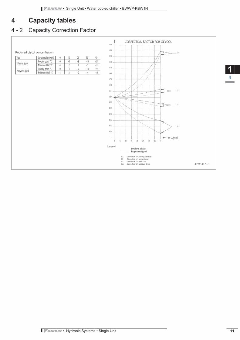
4 Capacity tables4 - 2 Capacity Correction Factor
14
4TW54179-1
CORRECTION FACTOR FOR GLYCOL
Ethylene glycolPropylene glycol
Legend
Kc Correction on cooling capacityKi Correction on power inputKf Correction on flow rateKp Correction on pressure drop
% Glycol
Required glycol concentration
Type Concentration (wt%) 0 10 20 30 40
Ethylene glycolFreezing point °C 0 -4 -9 -16 -23Minimum LWE °C 4 2 0 -5 -11
Propylene glycolFreezing point °C 0 -3 -7 -13 -22Minimum LWE °C 4 3 -2 -4 -10
ECDEN10-411_EWWP-EWLP-KBW1N.pdf 13 10/19/2010 9:38:38 AM

• Single Unit • Water cooled chiller • EWWP-KBW1N
• Hydronic Systems • Single Unit12
5 Dimensional drawings5 - 1 Dimensional Drawings
15
3TW55254-1B
EWWP014-035K W1N
Required service spacearound the unit
1 Compressor
2 Evaporator
3 Condenser
4 Switchbox
5 Chilled water in
6 Chilled water out
7 Condenser water out
8 Condenser water in
9 Evaporator entering water temperature sensor
10 Freeze up sensor
11 Condensor entering water temperature sensor
12 Digital display controller
13 Power supply intake (J 48)
14 Ballvalve
15 Water filter
16 Air purge
17 T-joint for air purge
18 Flow switch
19 Main switch
20 Flow switch pipe
View A-A
Scale 1/18
B
ECDEN10-411_EWWP-EWLP-KBW1N.pdf 14 10/19/2010 9:38:38 AM

• Hydronic Systems • Single Unit 13
• Single Unit • Water cooled chiller • EWWP-KBW1N
5 Dimensional drawings5 - 1 Dimensional Drawings
15
3TW55304-1B
EWWP045-065K W1N
Required service spacearound the unit
1 Compressor
2 Evaporator
3 Condenser
4 Switchbox
5 Chilled water in
6 Chilled water out
7 Condenser water out
8 Condenser water in
9 Evaporator entering water temperature sensor
10 Freeze up sensor
11 Condensor entering water temperature sensor
12 Digital display controller
13 Power supply intake (J 48)
14 Ballvalve
15 Water filter
16 Air purge
17 T-joint for air purge
18 Flow switch
19 Main switch
20 Flow switch pipe
View A-A
Scale 1/18
B
ECDEN10-411_EWWP-EWLP-KBW1N.pdf 15 10/19/2010 9:38:39 AM

• Single Unit • Water cooled chiller • EWWP-KBW1N
• Hydronic Systems • Single Unit14
5 Dimensional drawings5 - 1 Dimensional Drawings
15
3TW53474-3B
EWWP090-130K W1N (32-48hp)
1 Compressor
2 Evaporator
3 Condenser
4 Switchbox
5 Chilled water in 1
6 Chilled water in 2
7 Chilled water out 1
8 Chilled water out 2
9 Condenser water out 1
10 Condenser water out 2
11 Condenser water in 1
12 Condenser water in 2
13 Evaporator entering water temperature sensor 1
14 Evaporator entering water temperature sensor 2
15 Freeze up sensor 1
16 Freeze up sensor 2
17 Condensor entering water temperature 1
18 Condensor entering water temperature 2
19 Digital display controller
20 Power supply intake (J 48)
backside
Scale 1/18
Required service space around the unit
B
ECDEN10-411_EWWP-EWLP-KBW1N.pdf 16 10/19/2010 9:38:40 AM
• Hydronic Systems • Single Unit 15
• Single Unit • Water cooled chiller • EWWP-KBW1N
5 Dimensional drawings5 - 1 Dimensional Drawings
15
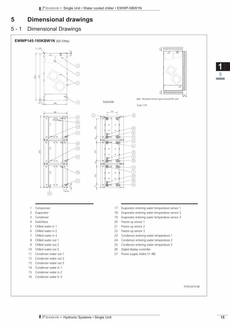
EWWP145-195K W1N (52-72hp)
3TW53474-4B
1 Compressor
2 Evaporator
3 Condenser
4 Switchbox
5 Chilled water in 1
6 Chilled water in 2
7 Chilled water in 3
8 Chilled water out 1
9 Chilled water out 2
10 Chilled water out 3
11 Condenser water out 1
12 Condenser water out 2
13 Condenser water out 3
14 Condenser water in 1
15 Condenser water in 2
16 Condenser water in 3
17 Evaporator entering water temperature sensor 1
18 Evaporator entering water temperature sensor 2
19 Evaporator entering water temperature sensor 3
20 Freeze up sensor 1
21 Freeze up sensor 2
22 Freeze up sensor 3
23 Condensor entering water temperature 1
24 Condensor entering water temperature 2
25 Condensor entering water temperature 3
26 Digital display controller
27 Power supply intake (J 48)
backsideScale 1/18
Required service space around the unit
B
ECDEN10-411_EWWP-EWLP-KBW1N.pdf 17 10/19/2010 9:38:41 AM

• Single Unit • Water cooled chiller • EWWP-KBW1N
• Hydronic Systems • Single Unit16
6 Centre of gravity6 - 1 Centre of Gravity
16
4TW53479-2
EWWP014-035K W1NB
4TW53479-3
EWWP045-065K W1NB
ECDEN10-411_EWWP-EWLP-KBW1N.pdf 18 10/19/2010 9:38:41 AM

• Hydronic Systems • Single Unit 17
• Single Unit • Water cooled chiller • EWWP-KBW1N
6 Centre of gravity6 - 1 Centre of Gravity
16
4TW53479-4
EWWP090-130K W1N (32-48hp)B
4TW53479-5
EWWP145-195K W1N (52-72hp)B
ECDEN10-411_EWWP-EWLP-KBW1N.pdf 19 10/19/2010 9:38:41 AM

• Single Unit • Water cooled chiller • EWWP-KBW1N
• Hydronic Systems • Single Unit18
7 Piping diagrams7 - 1 Piping Diagrams
17
3TW55255-1B
- - - - - - Field piping
O Check valve
L Flare connection
M Screw connection
N Flange connection
Z Pinched pipe
P Spinned pipe
EWWP014-035K W1N
M1C Compressor motor 1R3T Outlet water evap. temp. sensorR5T Inlet water cond. temp. sensorS1HP High pressure switchS4LP Low pressure switchR4T Freeze-up protectionS33T Discharge temperature controller
CondenserEvaporator
Expansion valveWater outlet
Water inlet
Water inlet
Water outlet
Filter
Filter
Shut off valveShut offvalve
Shut offvalve
Airpurge
Filter
Flow switchShut off valve
Air purge
B
ECDEN10-411_EWWP-EWLP-KBW1N.pdf 20 10/19/2010 9:38:41 AM

• Hydronic Systems • Single Unit 19
• Single Unit • Water cooled chiller • EWWP-KBW1N
7 Piping diagrams7 - 1 Piping Diagrams
17
3TW55305-1B
- - - - - - Field piping
O Check valve
L Flare connection
M Screw connection
N Flange connection
Z Pinched pipe
P Spinned pipe
EWWP045-065K W1N
M1-2C Compressor motorR4T Freeze-up protectionR5T Inlet water cond. temp. sensorS1HP High pressure switchS2HP High pressure switchS4LP Low pressure switchS5LP Low pressure switchR3T Inlet water evap. temp. sensorQ1D Discharge temperature controllerQ2D Discharge temperature controller
CondenserEvaporatorFilter
Water outlet
Water inlet
Water inlet
Water outlet
FilterFlow switchShut offvalve
Shut off valve Shut off valve
Shut offvalve
Airpurge Air purge
Filter
Filter
Expansion valve
Expansion valve
B
ECDEN10-411_EWWP-EWLP-KBW1N.pdf 21 10/19/2010 9:38:42 AM

• Single Unit • Water cooled chiller • EWWP-KBW1N
• Hydronic Systems • Single Unit20
7 Piping diagrams7 - 1 Piping Diagrams
17
3TW53475-3
O Check valve
L Flare connection
M Screw connection
N Flange connection
Z Pinched pipe
P Spinned pipe
EWWP090-130K W1N (32-48hp)
M1C-M2C Compressor motorR4T Freeze-up protectionR5T Inlet water cond. temp. sensorS1HP High pressure switchS2HP High pressure switchS4LP Low pressure switchS5LP Low pressure switchR3T Inlet water evap. temp. sensorQ1D Discharge temperature controllerQ2D Discharge temperature controller
Condenser Evaporator
Filter
Water outlet
Water inlet
Water inlet
Water outlet
Filter
Water outlet
Water inlet
Filter
Filter
EvaporatorCondenser
Water inlet
Water outlet
B
ECDEN10-411_EWWP-EWLP-KBW1N.pdf 22 10/19/2010 9:38:42 AM

• Hydronic Systems • Single Unit 21
• Single Unit • Water cooled chiller • EWWP-KBW1N
7 Piping diagrams7 - 1 Piping Diagrams
17
3TW53475-4
O Check valve
L Flare connection
M Screw connection
N Flange connection
Z Pinched pipe
P Spinned pipe
EWWP145-195K W1N (52-72hp)
M1C-M2C Compressor motorR4T Freeze-up protectionR5T Inlet water cond. temp. sensorS1HP High pressure switchS2HP High pressure switchS4LP Low pressure switchS5LP Low pressure switchR3T Inlet water evap. temp. sensorQ1D Discharge temperature controllerQ2D Discharge temperature controller
Cond
ense
rEv
apor
ator
Filte
r
Wat
erou
tlet
Wat
erin
let
Wat
erin
let
Wat
erou
tlet
Filte
r
Wat
erou
tlet
Wat
erin
let
Filte
r
Filte
r
Evap
orat
orCo
nden
ser
Wat
erin
let
Wat
erou
tlet
Evap
orat
or
Wat
erou
tlet
Wat
erin
let
Filte
r
Filte
r
Wat
erin
let
Wat
erou
tlet
Cond
ense
r
B
ECDEN10-411_EWWP-EWLP-KBW1N.pdf 23 10/19/2010 9:38:43 AM

• Single Unit • Water cooled chiller • EWWP-KBW1N
• Hydronic Systems • Single Unit22
8 Wiring diagrams8 - 1 Wiring Diagrams - Three Phase
18
Not standard includedNot possible as option Possible as option
Obligatory # # #Not obligatory
A2P A1P
DIGITAL INPUTSDI1 Reverse phase detection (L1-N)DI2 Reverse phase detection (N-L3)DI3 M1C ON detectionDI4 M2C ON detectionDI5 Safety device detectionDI6 Pump ON detectionDI7 – –DI8 – –DI9 – –DI10 Reverse valve request
DIGITAL INPUTSX1 (ID1-GND) : Flow switchX1 (ID2-GND) : Remote C/H selectionX1 (ID3-GND) : High pressure switch + discharge protector + overcurrentX1 (ID4-GND) : Low pressure switchX1 (ID5-GND) : Remote On/OffDIGITAL OUTPUTS (RELAYS)X2 (C1/2-NO1) : Compressor M1C onX2 (C1/2-NO2) : Compressor M2C onX2 (C3/4-NO3) : Voltage free contact for pumpX2 (C3/4-NO4) : Reversing valveX2 (C5-NO5) : Alarm voltage free contact
DIGITAL OUTPUTS (RELAYS)RY1 Reversed phase protectorRY3 Pump/general operationRY9 M1C off (during defrost)RY10 M2C off (during defrost)
ANALOG INPUTSX1 (B1-GND) : evap. inlet water t°X1 (B2-GND) : evap. outlet water t°X1 (B3-GND) : cond. inlet water t°
OTHERSHAP Light emitting diode (service monitor green)H1P,H2P Light emitting diode (service monitor red)S1A Dipswitch (unit setting)S2A Dipswitch (defr. & fan setting)
ANALOG OUTPUTSX1 (Y-GND)
NOTES
1. 1 : Terminal 1, 2 : Wire 2, : Field wiring to be in accordance with the local electrical regulations,
: Earth wiring, : Option, : PCB, : outside switchbox2. If compressor rotates reversely, it may be damaged3. WC: Watercooled chiller RC: Unit with remote condensor4. Optional: - EKAC10C = Address card kit for Modbus or remote user interface connection - EKSS = softstart - EKRUMCA = Remote user interface4. Terminals for fi eldwiring X1M: H3-6P,Y3R,K1-2F: output terminal for fi eldwiring (voltage free contact max 2A / output) X3M: S7S,S9S: Input terminal for fi eldwiring (don’t connect voltage)(switch load 6mA / 30VDC)5. Y3R is activated in cooling mode S7S open = heating S7S closed = cooling6. Dipswitch setting
S2A dipswitch: Defrost & Fan settingno meaning for WC CO & WC CL CO
S1A dipswitch: Unit setting1 > Off= 1 circuit On= 2 circuit234 > Off Off Off = WC CO & WC CL CO Off On Off = AC CO On Off Off = AC HP (without compr. stop for defrost cycle) On Off On = AC HP (with compr. stop for defrost cycle)
7. Pump contact
3N~50Hz 400V
EWLP012-065KBW1N
All models (400V)
Fuses + overcurrent WC014RC012
WC022RC020
WC028RC026
WC035RC030
WC045RC040
WC055RC055
WC065RC065
F1,F2,F3 (=gL/gG) 3x16A 3x20A 3x25A 3x32A 3x40A 3x50A 3x50AF4 8A 8A 8A 8A 8A 8A 8AF5 250mAT 250mAT 250mAT 250mAT 250mAT 250mAT 250mATF1U 5A 5A 5A 5A 5A 5A 5AF3U 315mAT 315mAT 315mAT 315mAT 315mAT 315mAT 315mATK4S 9A 14.5A 18.5A 22A 14A 18A 20AK5S – – – – 14A 18A 20A
Y3R * Reverse valve of water circuit R3T Evaporator inlet water temperature sensor F3U Fuse controller PCBY1S,Y2S Liquid solenoid valve circuit 1, circuit 2 Q1D,Q2D Discharge thermal protector circuit 1, circuit 2 F1U Fuse I/O PCBX1-82(A/B/M) Connectors PE Main earth terminal F6 # Fuse for pumpcontactorTR2 Transfo 230V-24V for supply of I/O PCB M1C,M2C Compressor motor circuit 1, circuit 2 F5 # # Surge proof fuseTR1 Transfo 230V-24V for supply of controller PCB K1P * Pump contactor F4 Fuse I/O PCBS12M Main isolator switch K1F,K2F # Fan contactor F1,F2,F3 # Main fuses for the unitS10L Flowswitch K6S * Overcurrent relay pump E1H,E2H Crankcase heater circuit 1, circuit 2S9S * Switch for remote start/stop or dual setpoint K4S,K5S Overcurrent relay circuit 1, circuit 2 A72P ** PCB: Power supply card
S7S * Switch for remote cooling/heating selection or dual setpoint
K1M, K2M Compressor contactor circuit 1, circuit 2 A71P ** PCB: Remote user interfaceM1C,M2C Compressor motor circuit 1, circuit 2 A3P ** PCB: Address card
S4LP,S5LP Low pressure switch circuit 1, circuit 2 H6P * Indication lamp general operation A2P PCB: I/O PCBS1HP,S2HP High pressure switch circuit 1, circuit 2 H5P * Indication lamp operation compressor 2 A1P PCB: controller PCBR5T Condensor inlet water temperature sensor H4P * Indication lamp operation compressor 1R4T Evaporator outlet water temperature sensor H3P * Indication lamp alarm
1 21 2 3 4
Defrost tempS2A
UnitS1A
Only for WC-045-065 / RC 040-065
Only for WC-045-065 / RC 040-065
Only for WC-045-065 / RC 040-065
Only for WC-045-065 / RC 040-065
ForWC 014-035RC 012-030
For WC 014-035 / RC 012-030
ForWC 045-065RC 040-065
For WC 045-065 / RC 040-065
Only for RC units Only for RC units
Only for RC unitsOnly for RC unitsOnly for RC unitsOnly for RC units
Only for WC-045-065 / RC 040-065
Option kit:EKAC10C
Option kit:EKRUMCA
RS485Modbus or EKRUMCA connection
Remoteuser interface
1TW60146-1
ECDEN10-411_EWWP-EWLP-KBW1N.pdf 24 10/19/2010 9:38:43 AM

• Hydronic Systems • Single Unit 23
• Single Unit • Water cooled chiller • EWWP-KBW1N
9 Sound data9 - 1 Sound Power Spectrum
19
4TW57197-1
EWWP014-028K W1N (5-10hp)
Soun
dpo
wer
leve
l(dB
)
LinearOctave band center frequency (Hz)
NOTESOption low noise = -3dBa
B
4TW57197-2
EWWP035K W1N (12hp)
Soun
dpo
wer
leve
l(dB
)
LinearOctave band center frequency (Hz)
NOTESOption low noise = -3dBa
B
4TW57197-3
EWWP045-055K W1N (16-20hp)
Soun
dpo
wer
leve
l(dB
)
LinearOctave band center frequency (Hz)
NOTESOption low noise = -3dBa
B
4TW57197-4
EWWP065K W1N (24hp)
Soun
dpo
wer
leve
l(dB
)
LinearOctave band center frequency (Hz)
NOTESOption low noise = -3dBa
B
ECDEN10-411_EWWP-EWLP-KBW1N.pdf 25 10/19/2010 9:38:43 AM

• Single Unit • Water cooled chiller • EWWP-KBW1N
• Hydronic Systems • Single Unit24
9 Sound data9 - 1 Sound Power Spectrum
19
4TW57197-5
EWWP090-110K W1N (32-40hp)
Soun
dpo
wer
leve
l(dB
)
LinearOctave band center frequency (Hz)
NOTESOption low noise = -3dBa
B
4TW57197-6
EWWP120K W1N (44hp)
Soun
dpo
wer
leve
l(dB
)
LinearOctave band center frequency (Hz)
NOTESOption low noise = -3dBa
B
4TW57197-7
EWWP130K W1N (48hp)
Soun
dpo
wer
leve
l(dB
)
LinearOctave band center frequency (Hz)
NOTESOption low noise = -3dBa
B
4TW57197-8
EWWP145-165K W1N (52-60hp)
Soun
dpo
wer
leve
l(dB
)
LinearOctave band center frequency (Hz)
NOTESOption low noise = -3dBa
B
ECDEN10-411_EWWP-EWLP-KBW1N.pdf 26 10/19/2010 9:38:45 AM

• Hydronic Systems • Single Unit 25
• Single Unit • Water cooled chiller • EWWP-KBW1N
9 Sound data9 - 1 Sound Power Spectrum
19
4TW57197-9
EWWP175K W1N (64hp)
Soun
dpo
wer
leve
l(dB
)
LinearOctave band center frequency (Hz)
NOTESOption low noise = -3dBa
B
4TW57197-10
EWWP185K W1N (68hp)
Soun
dpo
wer
leve
l(dB
)
LinearOctave band center frequency (Hz)
NOTESOption low noise = -3dBa
B
4TW57197-11
EWWP195K W1N (72hp)
Soun
dpo
wer
leve
l(dB
)
LinearOctave band center frequency (Hz)
NOTESOption low noise = -3dBa
B
ECDEN10-411_EWWP-EWLP-KBW1N.pdf 27 10/19/2010 9:38:46 AM

• Single Unit • Water cooled chiller • EWWP-KBW1N
• Hydronic Systems • Single Unit26
10 Operation range10 - 1 Operation Range
110
4TW57193-1
Glycol Water
EWWP014-035K W1N
∗ LWE = Leaving Water Evaporator (°C)∗ LWC = Leaving Water Condenser (°C)
B
ECDEN10-411_EWWP-EWLP-KBW1N.pdf 28 10/19/2010 9:38:47 AM

• Hydronic Systems • Single Unit 27
• Single Unit • Water cooled chiller • EWWP-KBW1N
10 Operation range10 - 1 Operation Range
110
4TW53473-1B
Glycol Water
EWWP045-065K W1N
90kW (32hp) - 195kW (72hp)
LWE = Leaving Water Evaporator (°C)LWC = Leaving Water Condenser (°C)
B
ECDEN10-411_EWWP-EWLP-KBW1N.pdf 29 10/19/2010 9:38:48 AM

• Single Unit • Water cooled chiller • EWWP-KBW1N
• Hydronic Systems • Single Unit28
11 Hydraulic performance11 - 1 Water Pressure Drop Curve Evaporator/Condenser
111
4TW57199-1A
EWWP014-035K W1N
Water flow rate (l/min)
Water flow rate (l/min)
Pres
sure
drop
(mH
2O)
Pres
sure
drop
(mH
2O)
Pressure drop evaporator
Pressure drop condenser
B
ECDEN10-411_EWWP-EWLP-KBW1N.pdf 30 10/19/2010 9:38:48 AM

• Hydronic Systems • Single Unit 29
• Single Unit • Water cooled chiller • EWWP-KBW1N
11 Hydraulic performance11 - 1 Water Pressure Drop Curve Evaporator/Condenser
111
4TW57239-1
EWWP045-065K W1N
Water flow rate (l/min)
Water flow rate (l/min)
Pres
sure
drop
(mH
2O)
Pres
sure
drop
(mH
2O)
Pressure drop evaporator
Pressure drop condenser
B
ECDEN10-411_EWWP-EWLP-KBW1N.pdf 31 10/19/2010 9:38:48 AM

• Single Unit • Water cooled chiller • EWWP-KBW1N
• Hydronic Systems • Single Unit30
11 Hydraulic performance11 - 1 Water Pressure Drop Curve Evaporator/Condenser
111
4TW53479-1A
EWWP145-195K W1N (52-72hp)
Water flow rate (l/min)
Water flow rate (l/min)
Pres
sure
drop
(mH
2O)
Pres
sure
drop
(mH
2O)
Pressure drop evaporator
Pressure drop condenser
Warning: Selecting a flow outside the curves can cause damage to or malfunction of the unit. See alsominimum and maximum allowed water flowrate in the technical specifications.
B
ECDEN10-411_EWWP-EWLP-KBW1N.pdf 32 10/19/2010 9:38:48 AM

• Hydronic Systems • Single Unit 31
• Single Unit • Water cooled condenserless chiller • EWLP-KBW1N
TABLE OF CONTENTSEWLP-KBW1N
1 Features . . . . . . . . . . . . . . . . . . . . . . . . . . . . . . . . . . . . . . . . . . . . . . . . . . . . . . . . . . . . 32
2 Specifications . . . . . . . . . . . . . . . . . . . . . . . . . . . . . . . . . . . . . . . . . . . . . . . . . . . . . . 33Technical Specifications . . . . . . . . . . . . . . . . . . . . . . . . . . . . . . . . . . . . . . . . . . . . 33Electrical Specifications . . . . . . . . . . . . . . . . . . . . . . . . . . . . . . . . . . . . . . . . . . . . . 33
3 Options . . . . . . . . . . . . . . . . . . . . . . . . . . . . . . . . . . . . . . . . . . . . . . . . . . . . . . . . . . . . . 34Options . . . . . . . . . . . . . . . . . . . . . . . . . . . . . . . . . . . . . . . . . . . . . . . . . . . . . . . . . . . . . . 34
4 Capacity tables . . . . . . . . . . . . . . . . . . . . . . . . . . . . . . . . . . . . . . . . . . . . . . . . . . . . 35Cooling Capacity Tables . . . . . . . . . . . . . . . . . . . . . . . . . . . . . . . . . . . . . . . . . . . . 35Capacity Correction Factor . . . . . . . . . . . . . . . . . . . . . . . . . . . . . . . . . . . . . . . . . . 36
5 Dimensional drawings . . . . . . . . . . . . . . . . . . . . . . . . . . . . . . . . . . . . . . . . . . . . 37Dimensional Drawings . . . . . . . . . . . . . . . . . . . . . . . . . . . . . . . . . . . . . . . . . . . . . . 37
6 Centre of gravity . . . . . . . . . . . . . . . . . . . . . . . . . . . . . . . . . . . . . . . . . . . . . . . . . . . 39Centre of Gravity . . . . . . . . . . . . . . . . . . . . . . . . . . . . . . . . . . . . . . . . . . . . . . . . . . . . 39
7 Piping diagrams . . . . . . . . . . . . . . . . . . . . . . . . . . . . . . . . . . . . . . . . . . . . . . . . . . . 40Piping Diagrams . . . . . . . . . . . . . . . . . . . . . . . . . . . . . . . . . . . . . . . . . . . . . . . . . . . . 40
8 Wiring diagrams . . . . . . . . . . . . . . . . . . . . . . . . . . . . . . . . . . . . . . . . . . . . . . . . . . . 42Wiring Diagrams - Three Phase . . . . . . . . . . . . . . . . . . . . . . . . . . . . . . . . . . . . 42
9 Sound data . . . . . . . . . . . . . . . . . . . . . . . . . . . . . . . . . . . . . . . . . . . . . . . . . . . . . . . . . 43Sound Power Spectrum . . . . . . . . . . . . . . . . . . . . . . . . . . . . . . . . . . . . . . . . . . . . . 43
10 Operation range . . . . . . . . . . . . . . . . . . . . . . . . . . . . . . . . . . . . . . . . . . . . . . . . . . . 44Operation Range . . . . . . . . . . . . . . . . . . . . . . . . . . . . . . . . . . . . . . . . . . . . . . . . . . . . 44
11 Hydraulic performance. . . . . . . . . . . . . . . . . . . . . . . . . . . . . . . . . . . . . . . . . . . . 46Water Pressure Drop Curve Evaporator/Condenser . . . . . . . . . . . . . . . . 46
ECDEN10-411_EWWP-EWLP-KBW1N.pdf 33 10/19/2010 9:38:49 AM

• Single Unit • Water cooled condenserless chiller • EWLP-KBW1N
• Hydronic Systems • Single Unit32
1 Features
21
Single Unit Hydronic Sys EWLP-KBW1N Water coole • Daikin scroll compressor
• Optimised for use with R-407C
• Electronic DDC controller
• Low operating sound level
• Low energy consumption
• Compact dimensions and low refrigerant volume
• Easy installation and maintenance
• Stainless steel plate heat exchanger
• Compatible with hydraulic module
• Standard integrated: main switch, pressure ports, flow switch, filter, shut-off valves and air purge
ECDEN10-411_EWWP-EWLP-KBW1N.pdf 34 10/19/2010 9:38:49 AM

• Hydronic Systems • Single Unit 33
• Single Unit • Water cooled condenserless chiller • EWLP-KBW1N
2 Specifications
22
Notes(1)Cooling: entering evaporator water temp. 12ºC; leaving evaporator water temp. 7ºC; condensing temp. 45ºC; liquid temp. 40ºC; standard: Eurovent. This power input includes beside the power to the unit an addition for the required pump power input.(2)Cooling: entering evaporator water temp. 12ºC; leaving evaporator water temp. 7ºC; condensing temp. bubble 45ºC; liquid temp. 40ºC; standard: Eurovent 6/C/003; condensing temp. bubble corresponds to compressor discharge pressure.
2-1 Technical SpecificationsEWLP012KBW1N
EWLP020KBW1N
EWLP026KBW1N
EWLP030KBW1N
EWLP040KBW1N
EWLP055KBW1N
EWLP065KBW1N
Cooling capacity Nom. kW 12.1 (1) 20.0 (1) 26.8 (1) 31.2 (1) 40.0 (1) 53.7 (1) 62.4 (1)Capacity steps number 1 2Power input Cooling Nom. kW 4.2 (2) 6.6 (2) 8.5 (2) 10.1 (2) 13.4 (2) 17.8 (2) 20.3 (2)Casing Colour Ivory white (Munsell code: 5Y7.5/1)
Material Polyester painted steel plateDimensions Unit Height mm 600
Width mm 600Depth mm 600 1,200
Weight Unit kg 108 141 147 151 252 265 274Water heat exchanger - evaporator
Minimum water volume in the system l 62 103 134 155 205 268 311Water flow rate Min. l/min 17 29 38 45 57 77 89
Nom. l/min 35 57 77 89 115 154 179Max. l/min 69 115 153 179 229 307 358
Insulation material Polyethylene foamModel Quantity 1Type Brazed plate
Sound power level Cooling Nom. dBA 64 71 67 74Compressor Type Hermetically sealed scroll compressor
Quantity 1 2Model JT140BF-YE JT212DA-YE JT300DA-YE JT335DA-YE JT212DA-YE JT300DA-YE JT335DA-YESpeed rpm 2,900Crankcase heater W 33Oil Charged volume l 1.5 2.7
Refrigerant Type R-407CControl Thermostatic expansion valveCircuits Quantity 1 2
Refrigerant oil Type FVC68DPiping connections Evaporator water inlet/outlet FBSP 25mm FBSP 40mm
Evaporator water drain Field installation
2-2 Electrical SpecificationsEWLP012KBW1N
EWLP020KBW1N
EWLP026KBW1N
EWLP030KBW1N
EWLP040KBW1N
EWLP055KBW1N
EWLP065KBW1N
Compressor Phase 3~Frequency Hz 50Voltage V 400Starting current A 49 79 109 129 79 109 129Nominal running current (RLA) A 7.4 11.5 14.3 16.6 11.5 14.3 16.6Maximum running current A 9 14.5 18.5 22 14 18 20Starting method Direct on line
Power supply Name W1Phase 3N~Frequency Hz 50Voltage V 400Voltage range Min. % -10
Max. % 10Unit Starting current A 49 79 109 129 93 127 149
Current Zmax Text 0.27 + j0.17 0.22 + j0.13 0.19 + j0.12 0.20 + j0.12 0.18 + j0.12 0.18 + j0.11Nominal running current (RLA)
Cooling A 7.4 11.5 14.3 16.6 23.0 28.7 33.3
Maximum running current A 9 14.5 18.5 22 28 36 40Recommended fuses according to IEC standard 269-2
3 x 16aM 3 x 20aM 3 x 25aM 3 x 35aM 3 x 40aM 3 x 50aM
ECDEN10-411_EWWP-EWLP-KBW1N.pdf 35 10/19/2010 9:38:49 AM

• Single Unit • Water cooled condenserless chiller • EWLP-KBW1N
• Hydronic Systems • Single Unit34
3 Options3 - 1 Options
23
EWWP-KBW1
EWLP-KBW1
4TW60149-5
Optional equipment for EWW/LP-KBW1
Modelnumber
EWWP014KBW1N* EWWP045KBW1N* EWLP012KBW1N* EWLP040KBW1N*EWWP022KBW1N* EWWP055KBW1N* EWLP020KBW1N* EWLP055KBW1N*EWWP028KBW1N* EWWP065KBW1N* EWLP026KBW1N* EWLP065KBW1N*EWWP035KBW1N* EWLP030KBW1N*
Option number Option description Unit size Availability
014WC - 012RC 022WC - 020RC 028WC - 026RC 035WC - 030RC 045WC - 040RC 055WC - 055RC 065WC - 065RC
Standard unit
Not completely combinable options
ZH Glycol operation chilled water temp down to -5°C Factory mountedZL Glycol operation chilled water temp down to -10°C Factory mounted
Available kits
EKAC10C Address card for connection to BMS or Remote user interface
Kit
EKRUMCA Remote installed user interface KitEKLS1 Low noise operation EUW*5KZW1 1 – – – – – – KitEKLS2 Low noise operation EUW*8-24KZW1 – 1 1 1 2 2 2 KitEHMC10AV1010/1080 Hydraulic module – – – – – KitEHMC15AV1010/1080 Hydraulic module – – – – – KitEHMC30AV1010/1080 Hydraulic module – – – – Kit
NOTES
1. std = standard on unit = availablex = available and a quantity of x is needed for this unit size
– = not availableHatched area = preliminary data
3. * = option number4. To install EKRUMCA => EKAC10C needs to be installed on the unit.5. EKAC10C : this address card allows direct connection to MODBUS BMS system
ECDEN10-411_EWWP-EWLP-KBW1N.pdf 36 10/19/2010 9:38:49 AM

• Hydronic Systems • Single Unit 35
• Single Unit • Water cooled condenserless chiller • EWLP-KBW1N
4 Capacity tables4 - 1 Cooling Capacity Tables
24
Tc [°C] 25 30 35 40 45 50 55 60LWE [°C] CC PI CC PI CC PI CC PI CC PI CC PI CC PI CC PI
4TW57292-1A
NOTES1 CC
According to Eurovent rating standard 6/C/003-2003 and valid for chilled water range Dt=3-8°C.2 PI
According to Eurovent rating standard 6/C/003-2003 (compressor + control circuit).
SYMBOLSCC : Cooling capacity (kW)
PI : Power input (kW)
TC : Condensing temperature bubble (°C)
LWE : Leaving water evaporator (°C)
ECDEN10-411_EWWP-EWLP-KBW1N.pdf 37 10/19/2010 9:38:49 AM
• Single Unit • Water cooled condenserless chiller • EWLP-KBW1N
• Hydronic Systems • Single Unit36
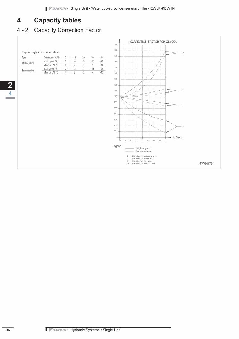
4 Capacity tables4 - 2 Capacity Correction Factor
24
4TW54179-1
CORRECTION FACTOR FOR GLYCOL
Ethylene glycolPropylene glycol
Legend
Kc Correction on cooling capacityKi Correction on power inputKf Correction on flow rateKp Correction on pressure drop
% Glycol
Required glycol concentration
Type Concentration (wt%) 0 10 20 30 40
Ethylene glycolFreezing point °C 0 -4 -9 -16 -23Minimum LWE °C 4 2 0 -5 -11
Propylene glycolFreezing point °C 0 -3 -7 -13 -22Minimum LWE °C 4 3 -2 -4 -10
ECDEN10-411_EWWP-EWLP-KBW1N.pdf 38 10/19/2010 9:38:50 AM

• Hydronic Systems • Single Unit 37
• Single Unit • Water cooled condenserless chiller • EWLP-KBW1N
5 Dimensional drawings5 - 1 Dimensional Drawings
25
3TW55254-2B
EWLP012-030K W1N
Required service spacearound the unit
1 Compressor
2 Evaporator
3 Accumulator
4 Switchbox
5 Chilled water in
6 Chilled water out
7 Discharge stop valve
8 Liquid stop valve
9 Evaporator entering water temperature sensor
10 Freeze up sensor
11 Digital display controller
12 Power supply intake (J 48)
13 Ballvalve
14 Water filter
15 Air purge
16 T-joint for air purge
17 Flow switch
18 Main switch
19 Flow switch pipe
Scale: 1/18
View A-A Only for 5HP View A-A Only for 8-10-12HP
Scale: 1/12 Scale: 1/12
B
ECDEN10-411_EWWP-EWLP-KBW1N.pdf 39 10/19/2010 9:38:50 AM

• Single Unit • Water cooled condenserless chiller • EWLP-KBW1N
• Hydronic Systems • Single Unit38
5 Dimensional drawings5 - 1 Dimensional Drawings
25
3TW55304-2B
EWLP040-065K W1N
Required service spacearound the unit
1 Compressor
2 Evaporator
3 Accumulator
4 Switchbox
5 Chilled water in
6 Chilled water out
7 Discharge stop valve
8 Liquid stop valve
9 Evaporator entering water temperature sensor
10 Freeze up sensor
Scale: 1/18
View A-A
11 Digital display controller
12 Power supply intake (J 48)
13 Ballvalve
14 Water filter
15 Air purge
16 T-joint for air purge
17 Flow switch
18 Main switch
19 Flow switch pipe
B
ECDEN10-411_EWWP-EWLP-KBW1N.pdf 40 10/19/2010 9:38:51 AM

• Hydronic Systems • Single Unit 39
• Single Unit • Water cooled condenserless chiller • EWLP-KBW1N
6 Centre of gravity6 - 1 Centre of Gravity
26
4TW54629-2
EWLP012-030K W1NB
4TW54629-3
EWLP040-065K W1NB
ECDEN10-411_EWWP-EWLP-KBW1N.pdf 41 10/19/2010 9:38:51 AM

• Single Unit • Water cooled condenserless chiller • EWLP-KBW1N
• Hydronic Systems • Single Unit40
7 Piping diagrams7 - 1 Piping Diagrams
27
3TW55255-2B
- - - - - - Field piping
O Check valve
L Flare connection
M Screw connection
N Flange connection
Z Pinched pipe
P Spinned pipe
EWLP012-030K W1N
Y1S Liquid solenoid valveM1C Compressor motor 1R4T Freeze-up protectionS1HP High pressure switchS4LP Low pressure switchR3T Inlet water evap. temp. sensorQ1D Discharge temperature controller
Accumulator
Evaporator
Expansion valve
Water outlet
Water inlet
Filter
Shut off valve
Discharge stopvalve
Liquid stop valve
Airpurge
Filter
Flow switchShut offvalve
Sight glass withmoist indicator
Liquid solenoidvalve
B
ECDEN10-411_EWWP-EWLP-KBW1N.pdf 42 10/19/2010 9:38:52 AM

• Hydronic Systems • Single Unit 41
• Single Unit • Water cooled condenserless chiller • EWLP-KBW1N
7 Piping diagrams7 - 1 Piping Diagrams
27
3TW55305-2B
- - - - - - Field piping
O Check valve
L Flare connection
M Screw connection
N Flange connection
Z Pinched pipe
P Spinned pipe
EWLP040-065K W1N
Y1S Liquid solenoid valveY2S Liquid solenoid valveM1C Compressor motorM2C Compressor motorR4T Freeze-up protectionR5T Inlet water cond. temp. sensorS1HP High pressure switchS2HP High pressure switchS4LP Low pressure switchS5LP Low pressure switchR3T Inlet water evap. temp. sensorQ1D Discharge temperature controllerQ2D Discharge temperature controller
Liquid solenoidvalve
Evaporator
Filter
Water outlet
Water inlet
Discharge stop valve
Liquid stop valve
Sight glass withmoist indicator
Flow switchShut offvalve
Shut off valve
Liquid stop valve
Sight glass withmoist indicator
Airpurge
Discharge stop valve
Filter
Filter
Expansion valve
Expansion valve
Accumulator
Liquid solenoidvalve
Accumulator
B
ECDEN10-411_EWWP-EWLP-KBW1N.pdf 43 10/19/2010 9:38:53 AM
• Single Unit • Water cooled condenserless chiller • EWLP-KBW1N
• Hydronic Systems • Single Unit42
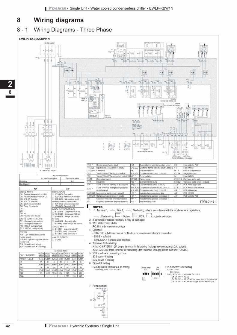
8 Wiring diagrams8 - 1 Wiring Diagrams - Three Phase
28
Not standard includedNot possible as option Possible as option
Obligatory # # #Not obligatory
A2P A1P
DIGITAL INPUTSDI1 Reverse phase detection (L1-N)DI2 Reverse phase detection (N-L3)DI3 M1C ON detectionDI4 M2C ON detectionDI5 Safety device detectionDI6 Pump ON detectionDI7 – –DI8 – –DI9 – –DI10 Reverse valve request
DIGITAL INPUTSX1 (ID1-GND) : Flow switchX1 (ID2-GND) : Remote C/H selectionX1 (ID3-GND) : High pressure switch + discharge protector + overcurrentX1 (ID4-GND) : Low pressure switchX1 (ID5-GND) : Remote On/OffDIGITAL OUTPUTS (RELAYS)X2 (C1/2-NO1) : Compressor M1C onX2 (C1/2-NO2) : Compressor M2C onX2 (C3/4-NO3) : Voltage free contact for pumpX2 (C3/4-NO4) : Reversing valveX2 (C5-NO5) : Alarm voltage free contact
DIGITAL OUTPUTS (RELAYS)RY1 Reversed phase protectorRY3 Pump/general operationRY9 M1C off (during defrost)RY10 M2C off (during defrost)
ANALOG INPUTSX1 (B1-GND) : evap. inlet water t°X1 (B2-GND) : evap. outlet water t°X1 (B3-GND) : cond. inlet water t°
OTHERSHAP Light emitting diode (service monitor green)H1P,H2P Light emitting diode (service monitor red)S1A Dipswitch (unit setting)S2A Dipswitch (defr. & fan setting)
ANALOG OUTPUTSX1 (Y-GND)
NOTES
1. 1 : Terminal 1, 2 : Wire 2, : Field wiring to be in accordance with the local electrical regulations,
: Earth wiring, : Option, : PCB, : outside switchbox2. If compressor rotates reversely, it may be damaged3. WC: Watercooled chiller RC: Unit with remote condensor4. Optional: - EKAC10C = Address card kit for Modbus or remote user interface connection - EKSS = softstart - EKRUMCA = Remote user interface4. Terminals for fi eldwiring X1M: H3-6P,Y3R,K1-2F: output terminal for fi eldwiring (voltage free contact max 2A / output) X3M: S7S,S9S: Input terminal for fi eldwiring (don’t connect voltage)(switch load 6mA / 30VDC)5. Y3R is activated in cooling mode S7S open = heating S7S closed = cooling6. Dipswitch setting
S2A dipswitch: Defrost & Fan settingno meaning for WC CO & WC CL CO
S1A dipswitch: Unit setting1 > Off= 1 circuit On= 2 circuit234 > Off Off Off = WC CO & WC CL CO Off On Off = AC CO On Off Off = AC HP (without compr. stop for defrost cycle) On Off On = AC HP (with compr. stop for defrost cycle)
7. Pump contact
3N~50Hz 400V
EWLP012-065KBW1N
All models (400V)
Fuses + overcurrent WC014RC012
WC022RC020
WC028RC026
WC035RC030
WC045RC040
WC055RC055
WC065RC065
F1,F2,F3 (=gL/gG) 3x16A 3x20A 3x25A 3x32A 3x40A 3x50A 3x50AF4 8A 8A 8A 8A 8A 8A 8AF5 250mAT 250mAT 250mAT 250mAT 250mAT 250mAT 250mATF1U 5A 5A 5A 5A 5A 5A 5AF3U 315mAT 315mAT 315mAT 315mAT 315mAT 315mAT 315mATK4S 9A 14.5A 18.5A 22A 14A 18A 20AK5S – – – – 14A 18A 20A
Y3R * Reverse valve of water circuit R3T Evaporator inlet water temperature sensor F3U Fuse controller PCBY1S,Y2S Liquid solenoid valve circuit 1, circuit 2 Q1D,Q2D Discharge thermal protector circuit 1, circuit 2 F1U Fuse I/O PCBX1-82(A/B/M) Connectors PE Main earth terminal F6 # Fuse for pumpcontactorTR2 Transfo 230V-24V for supply of I/O PCB M1C,M2C Compressor motor circuit 1, circuit 2 F5 # # Surge proof fuseTR1 Transfo 230V-24V for supply of controller PCB K1P * Pump contactor F4 Fuse I/O PCBS12M Main isolator switch K1F,K2F # Fan contactor F1,F2,F3 # Main fuses for the unitS10L Flowswitch K6S * Overcurrent relay pump E1H,E2H Crankcase heater circuit 1, circuit 2S9S * Switch for remote start/stop or dual setpoint K4S,K5S Overcurrent relay circuit 1, circuit 2 A72P ** PCB: Power supply card
S7S * Switch for remote cooling/heating selection or dual setpoint
K1M, K2M Compressor contactor circuit 1, circuit 2 A71P ** PCB: Remote user interfaceM1C,M2C Compressor motor circuit 1, circuit 2 A3P ** PCB: Address card
S4LP,S5LP Low pressure switch circuit 1, circuit 2 H6P * Indication lamp general operation A2P PCB: I/O PCBS1HP,S2HP High pressure switch circuit 1, circuit 2 H5P * Indication lamp operation compressor 2 A1P PCB: controller PCBR5T Condensor inlet water temperature sensor H4P * Indication lamp operation compressor 1R4T Evaporator outlet water temperature sensor H3P * Indication lamp alarm
1 21 2 3 4
Defrost tempS2A
UnitS1A
Only for WC-045-065 / RC 040-065
Only for WC-045-065 / RC 040-065
Only for WC-045-065 / RC 040-065
Only for WC-045-065 / RC 040-065
ForWC 014-035RC 012-030
For WC 014-035 / RC 012-030
ForWC 045-065RC 040-065
For WC 045-065 / RC 040-065
Only for RC units Only for RC units
Only for RC unitsOnly for RC unitsOnly for RC unitsOnly for RC units
Only for WC-045-065 / RC 040-065
Option kit:EKAC10C
Option kit:EKRUMCA
RS485Modbus or EKRUMCA connection
Remoteuser interface
1TW60146-1
ECDEN10-411_EWWP-EWLP-KBW1N.pdf 44 10/19/2010 9:38:53 AM

• Hydronic Systems • Single Unit 43
• Single Unit • Water cooled condenserless chiller • EWLP-KBW1N
9 Sound data9 - 1 Sound Power Spectrum
29
4TW57197-1
EWLP012-026K W1N
Soun
dpo
wer
leve
l(dB
)
LinearOctave band center frequency (Hz)
NOTESOption low noise = -3dBa
B
4TW57197-2
EWLP030K W1N
Soun
dpo
wer
leve
l(dB
)
LinearOctave band center frequency (Hz)
NOTESOption low noise = -3dBa
B
4TW57197-3
EWLP040-055K W1N
Soun
dpo
wer
leve
l(dB
)
LinearOctave band center frequency (Hz)
NOTESOption low noise = -3dBa
B
4TW57197-4
EWLP065K W1N
Soun
dpo
wer
leve
l(dB
)
LinearOctave band center frequency (Hz)
NOTESOption low noise = -3dBa
B
ECDEN10-411_EWWP-EWLP-KBW1N.pdf 45 10/19/2010 9:38:54 AM

• Single Unit • Water cooled condenserless chiller • EWLP-KBW1N
• Hydronic Systems • Single Unit44
10 Operation range10 - 1 Operation Range
210
4TW57293-1
Glycol Water
EWLP012-030K W1N
∗ LWE = Leaving Water Evaporator (°C)∗ CT = Condensing Temperature (°C)
B
ECDEN10-411_EWWP-EWLP-KBW1N.pdf 46 10/19/2010 9:38:55 AM

• Hydronic Systems • Single Unit 45
• Single Unit • Water cooled condenserless chiller • EWLP-KBW1N
10 Operation range10 - 1 Operation Range
210
4TW53473-2
Glycol Water
EWLP040-065K W1N
LWE = Leaving Water Evaporator (°C)CT = Condensing temperature (°C)
B
ECDEN10-411_EWWP-EWLP-KBW1N.pdf 47 10/19/2010 9:38:55 AM

• Single Unit • Water cooled condenserless chiller • EWLP-KBW1N
• Hydronic Systems • Single Unit46
11 Hydraulic performance11 - 1 Water Pressure Drop Curve Evaporator/Condenser
211
4TW57299-1A
Water flow rate (l/min)
Water flow rate (l/min)
Pres
sure
drop
[kPa
]Pr
essu
redr
op[k
Pa]
Pressure drop evaporator
Pressure drop condenser
Warning: Selecting a flow outside the curves can cause damage to or malfunction ofthe unit. See also minimum and maximum allowed water flowrange in the technicalspecifications.
ECDEN10-411_EWWP-EWLP-KBW1N.pdf 48 10/19/2010 9:38:55 AM

Naamloze Vennootschap - Zandvoordestraat 300, B-8400 Oostende - Belgium - www.daikin.eu - BE 0412 120 336 - RPR Oostende EC
DE
N1
0-4
11
A •
CD
• 0
8/1
0 •
Co
py
rig
ht
Da
ikin
Pre
par
ed
in B
elg
ium
by
Lan
no
o (
ww
w.la
nn
oo
pri
nt.
be
), a
com
pan
y w
ho
se c
on
cern
for
the
en
viro
nm
en
t is
se
t in
th
e E
MA
S an
d IS
O 1
40
01
sys
tem
s.
Re
spo
nsi
ble
Ed
ito
r: D
aik
in E
uro
pe
N.V
., Z
an
dv
oo
rde
stra
at
30
0,
B-8
40
0 O
ost
en
de
Daikin products are distributed by:
Daikin’s unique position as a manufacturer of air
conditioning equipment, compressors and refrigerants
has led to its close involvement in environmental issues.
For several years Daikin has had the intention to become
a leader in the provision of products that have limited
impact on the environment. This challenge demands the
eco design and development of a wide range of products
and an energy management system, resulting in energy
conservation and a reduction of waste.
Daikin Europe N.V. is participating in the EUROVENT
Certification Programme. Products are as listed in the
EUROVENT Directory of Certified Products.
The present publication is drawn up by way of information only and does not constitute an offer binding
upon Daikin Europe N.V.. Daikin Europe N.V. has compiled the content of this publication to the best of its
knowledge. No express or implied warranty is given for the completeness, accuracy, reliability or fitness for
particular purpose of its content and the products and services presented therein. Specifications are subject
to change without prior notice. Daikin Europe N.V. explicitly rejects any liability for any direct or indirect
damage, in the broadest sense, arising from or related to the use and/or interpretation of this publication. All
content is copyrighted by Daikin Europe N.V..
ECDEN10-411_EWWP-EWLP-KBW1N.pdf 49 10/19/2010 9:38:56 AM