chemiosmotic principles of solute transport in barley rootsableweb.org/volumes/vol-6/6-glass.pdf ·...
TRANSCRIPT
Chapter 6
Chemiosmotic Principles of Solute Transport in Barley Roots
Anthony D. M. Glass
Department of Botany University of British Columbia
Vancouver, B.C. V6T 1W5
Anthony Glass received his B.Sc. and Dip.Ed. from the University of Wales, U.K., and his Ph.D. from the University of British Columbia. He has taught high school biology, chemistry, and physics in the U.K. and Canada. He has taught at the university level at Massey University, New Zealand, and at the University of British Columbia, where he is currently a Professor of Botany. His research interest is in the regulation of ion transport.
© 1992 Anthony D. M. Glass
105
Reprinted from: Glass, A. D. M., 1992. Chemiosmotic Principles of solute transport in barley roots, Pages 105-120, in Tested studies for laboratory teaching, Volume 6 (C.A. Goldman, S.E. Andrews, P.L. Hauta, and R. Ketchum, Editors). Proceedings of the 6th Workshop/Conference of the Association for Biology Laboratory Education (ABLE), 161 pages.
- Copyright policy: http://www.zoo.utoronto.ca/able/volumes/copyright.htm
Although the laboratory exercises in ABLE proceedings volumes have been tested and due consideration has been given to safety, individuals performing these exercises must assume all responsibility for risk. The Association for Biology Laboratory Education (ABLE) disclaims any liability with regards to safety in connection with the use of the exercises in its proceedings volumes.
Association for Biology Laboratory Education (ABLE) ~ http://www.zoo.utoronto.ca/able
Chemiosmotic Solute Transport 106
Contents
Introduction....................................................................................................................106 Background Information for Students ...........................................................................107 Electrochemical Potentials.............................................................................................107 The Chemiosmotic Hypothesis ......................................................................................108 Notes for the Instructor ..................................................................................................111 Growth of Plants ............................................................................................................111 Experimental Equipment ...............................................................................................112 Experiments ...................................................................................................................116 Basic Experiment: K+/H+ Exchange ..............................................................................117 Suggested Variations .....................................................................................................117 Example of an Advanced Experiment ...........................................................................117 Literature Cited ..............................................................................................................119 Appendix A: Composition of Johnson's Modified Nutrient Solution............................120 Appendix B: Conversion of pH Changes to H+ Fluxes .................................................120
Introduction
The objective of this exercise is to demonstrate the apparent coupling between fluxes of H+ and other inorganic ions into roots of barley plants. By appropriate choice of treatments the student can establish that H+ efflux (which is associated with cation absorption) is an active transport (i.e., is against the electrochemical potential gradient for H+) and, hence, an energy-dependent process. The involvement of ATPase activity in this H+ transport can be shown by the use of a specific inhibitor (e.g., vanadate). These observations provide the student with an appropriate background for understanding chemiosmotic principles as applied to the synthesis of ATP in mitochondria and chloroplasts, and current interpretations of solute transport. In addition, the coupled H+/K+ exchanges which are demonstrated are associated with auxin-induced cell elongation, an important feature of the acid-growth theory of auxin action.
As a typical laboratory exercise, the student should be able to complete the required measurements in one 2- to 3-hour session. Tending to the growth of plants and preparation of various solutions might require an additional 1 to 2 hours prior to the laboratory period. Ideally, each group of students should have a two-place digital pH meter available to them so that continuous measurements can be made. In my laboratory we maintain 12 different experiment stations which are operated simultaneously. Each week students move to a new station so that costly duplications of equipment are unnecessary. Alternatively, several groups of students might share a single pH meter by taking samples of their solutions to the meter.
This exercise is technically quite simple and is therefore suitable for introductory biology courses or for more advanced cell or plant physiology courses. At the same time, by including additional exercises such as the isolation of membrane ATPases, the experiment might form the basis of a special (independent) project for senior students.
Chemiosmotic Solute Transport 107
*
Background Information for Students
Electrochemical Potentials
The definition of active transport as applied to the movement of charged solutes (e.g., H+) involves consideration of both the concentration (chemical potential) gradient and the electrical gradient against which an ion is moving. Since plant cell membranes are electrically polarized, with potential differences amounting to -100 to -200 mV, the consideration of the electrical potential difference is crucial in defining active transport.
The combined electrical and chemical potentials for a given ion is given by: ψµµ zF + a RT + = * ln
where µ = the standard state electrochemical potential R = the gas constant T = temperature in degrees Celsius lna = loge of the activity (concentration) of the ion under consideration z = charge (+1 for H+, -1 for NO3-) F = Faraday constant ψ = electrical potential Where a membrane separates two compartments, i (inside) and o (outside), the difference of electrochemical potential across the membrane is given by:
)zF + a (RT - )zF + a (RT = - = ooiioiio ψψµµµ lnln∆ (2)
aa RT + ) - zF( =
o
ioiio lnψψµ∆
(3) or
aa RT - ) - zF( =
i
ooiio lnψψµ∆
(4) For H+:
H - H RT 2.3 - ) zF( = i+
o+
H+io
loglogψµ ∆∆
or
pH RT 2.3 - ) zF( = H+
io∆∆∆ ψµ (5)
Thus, in considering the electrochemical potential gradient associated with the distribution of H+
across electrically polarized membranes, equation (5) permits the calculation of the gradient (in energy units, Joules mol-1) from a knowledge of the electrical potential difference (∆ψ) and ∆pH between the two compartments.
Chemiosmotic Solute Transport 108
Consider a ∆ψ = -100 mV and a ∆pH of 1.7 pH units. At 30°C the values of the various constants in equation (5) simplify the equation to:
pH 5790 - 96.5 = H+
io∆∆∆ ψµ (6)
Thus, in the above example:
mol Joules 19493- =
(1.7) 5790 - (-100) 96.5 = 1-
H+io
µ∆
(7) The negative value indicates that inside the cell (see equation 2) is considerably less than that
outside. That is, the free energy of H+ inside the cell is considerably less than outside, and consequently the transport of H+ to the cell exterior represents an active transport step.
The Chemiosmotic Hypothesis
Prior to Peter Mitchell's chemiosmotic hypothesis (1961) it was generally considered that ATP synthesis in mitochondria and chloroplasts occurred by mechanisms which were essentially similar to the biochemical reactions for ATP synthesis in glycolysis. In the latter process, this involves the formation of a phosphate intermediate (e.g., phosphoenolpyruvate) with a high free-energy of hydrolysis. ATP is then formed by transferring the phosphate group from this intermediate to ADP:
H - C H - C |
ATP + O = C ADP + P - O - C | |
H O O C H O O C
32
_→
This reaction is possible because phosphoenolpyruvate (PEP) has a high free energy of hydrolysis:
-14.7 kcal mol-1 compared to -8.2 kcal mol-1 for ATP hydrolysis. In the mitochondria and chloroplasts the energy necessary for generating the putative phosphate intermediates was thought to arise from the reduction/oxidation (redox) reactions of the electron transport chains. Despite years of attempting to identify the unknown phosphate intermediates no success was achieved.
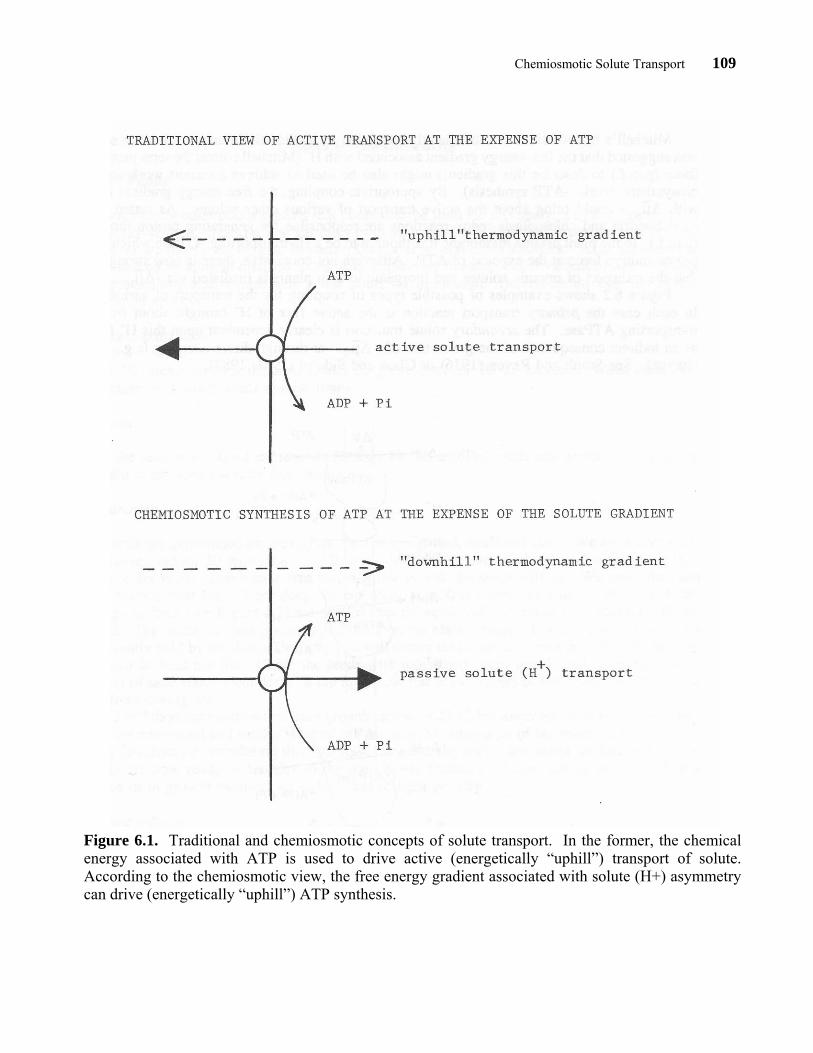
Peter Mitchell completely changed the direction of thinking in this area by proposing that the redox reactions generated a gradient of H+ across mitochondrial and chloroplast membranes, rather than a chemical intermediate. Mitchell proposed that the energy associated with this H+ gradient (see equation 5) was used to drive ATP synthesis. We are all familiar with the concept that ATP can be used to bring about active transport; the Mitchell hypothesis asks us to consider such a reaction proceeding in reverse. That is, as an ion, (H+) flows (“downhill”) along the electrochemical gradient it might bring about ATP synthesis (see Figure 6.1) through the action of a membrane ATPase operating in reverse. Strictly speaking we should perhaps refer to this as an ATP synthetase enzyme when it acts to generate ATP and use the term ATPase only when it hydrolyzes ATP.
Chemiosmotic Solute Transport 109
Figure 6.1. Traditional and chemiosmotic concepts of solute transport. In the former, the chemical energy associated with ATP is used to drive active (energetically “uphill”) transport of solute. According to the chemiosmotic view, the free energy gradient associated with solute (H+) asymmetry can drive (energetically “uphill”) ATP synthesis.
Chemiosmotic Solute Transport 110
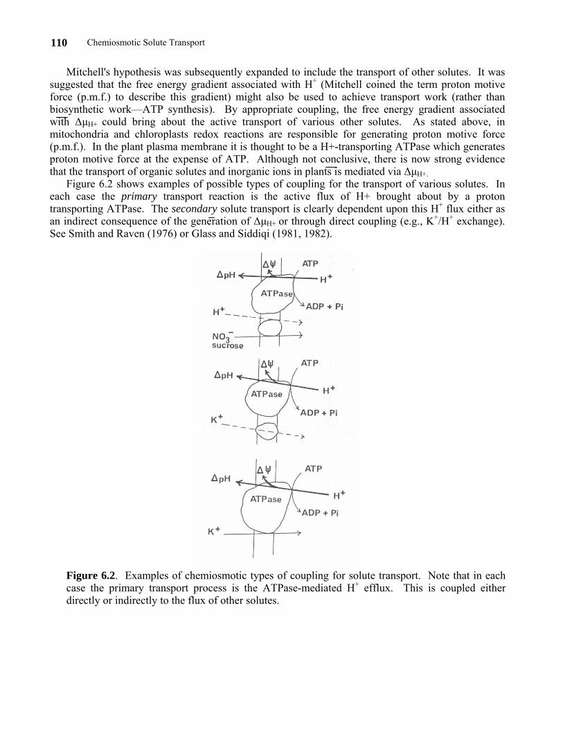
Mitchell's hypothesis was subsequently expanded to include the transport of other solutes. It was suggested that the free energy gradient associated with H+ (Mitchell coined the term proton motive force (p.m.f.) to describe this gradient) might also be used to achieve transport work (rather than biosynthetic work—ATP synthesis). By appropriate coupling, the free energy gradient associated with ∆µH+ could bring about the active transport of various other solutes. As stated above, in mitochondria and chloroplasts redox reactions are responsible for generating proton motive force (p.m.f.). In the plant plasma membrane it is thought to be a H+-transporting ATPase which generates proton motive force at the expense of ATP. Although not conclusive, there is now strong evidence that the transport of organic solutes and inorganic ions in plants is mediated via ∆µH+.
Figure 6.2 shows examples of possible types of coupling for the transport of various solutes. In each case the primary transport reaction is the active flux of H+ brought about by a proton transporting ATPase. The secondary solute transport is clearly dependent upon this H+ flux either as an indirect consequence of the generation of ∆µH+ or through direct coupling (e.g., K+/H+ exchange). See Smith and Raven (1976) or Glass and Siddiqi (1981, 1982).
Figure 6.2. Examples of chemiosmotic types of coupling for solute transport. Note that in each case the primary transport process is the ATPase-mediated H+ efflux. This is coupled either directly or indirectly to the flux of other solutes.
Chemiosmotic Solute Transport 111
Notes for the Instructor
Growth of Plants
Although many other plants species (e.g., corn) can be used for this study, we have found barley to be most convenient. Select a few varieties from your seed merchant and experiment with them. In Vancouver we have used Fergus, Bonanza, Galt, and several other varieties. Some varieties can be germinated by aerating in distilled water prior to planting in sand. Other varieties respond poorly to overnight soaking and require only a few hours for imbibition. Determine the best the system with your own variety.
Surface sterilization Use a 1% bleach to treat the seed (about 20 g per disc) for 10–15 minutes. Wash bleach off and
then rinse in distilled water several times. Aeration Place the seed in a 500 ml erlenmeyer flask in 400 ml distilled water and aerate for 1–2 hours, or
overnight if the seed tolerates this treatment. Germination The seeds are germinated on plexiglass discs in moistened, sterilized sand. We autoclave well-
washed coarse sand for 20 minutes at 14.7 lbs in-2. Moisten the sand with distilled water (15 g H2O per 100 g of dry sand). Don't have free water visible or else the seeds will rot. We place the sand in plastic horticultural flats (7-cm deep, 26-cm wide, and 50-cm long) to a depth of about 4 cm. The plexiglass discs (see Figure 6.3) are pushed into the sand until the gauze is in contact with the moist sand. The seeds are then placed in the discs on the plastic gauze. Use as many seeds as can be conveniently held by the disc. This way you will obtain luxuriant root growth. As many as eight (8) discs can be held per flat. Cover the seeds with moistened paper towels and cover the towels with a layer of sand about 2-cm deep. Wrap the whole flat in two layers of aluminum foil to prevent the sand from drying out.
After 2 or 3 days germination (we use a growth cabinet at 23°C, but lower temperatures are suitable) the seeds are uncovered and sand is washed off the roots by using a jet of tap water. Ungerminated seeds may fall from the disc during this operation but generally only a few seeds are lost in this way. The plants are now ready to transfer to the hydroponic facilities. These can be maintained in a greenhouse or in growth cabinets set at 18 hours of light per day.
Nutrient solutions The simplest solution which will provide for the growth of plants is a 0.5 mM CaSO4 solution
which should be replaced every 3 days. Since the seeds contain considerable reserves of inorganic ions there is no need for additional elements, providing the plants are used by the time they are 7-days-old. The key to obtaining high rates of ion uptake is to ensure that plants are deprived of inorganic nutrients prior to the actual experiment. With each day of deprivation the plants' reserves diminish (due to growth) and rates of ion absorption increase. However after 7–8 days the plant may show severe deficiency symptoms and declining rates of ion transport. To obtain more vigorous plant growth with high rates of ion absorption we have provided a complete inorganic nutrient solution such as 1/100 strength Johnson's Modified Medium; see Appendix A and/or Epstein (1972:39). This solution is provided at the outset and is not subsequently replenished. By 7–8 days there may be 5–8 g (fresh weight) of root material per disc, sufficient to obtain high rates of ion absorption during the
Chemiosmotic Solute Transport 112
experimental period. The nutrients provided initially are sufficient to promote good growth but insufficient to depress rates of absorption.
Experimental Equipment
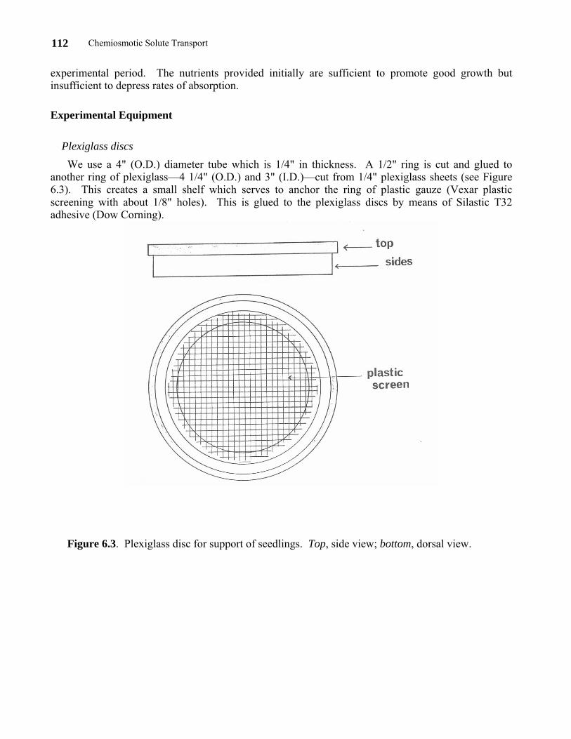
Plexiglass discs We use a 4" (O.D.) diameter tube which is 1/4" in thickness. A 1/2" ring is cut and glued to
another ring of plexiglass—4 1/4" (O.D.) and 3" (I.D.)—cut from 1/4" plexiglass sheets (see Figure 6.3). This creates a small shelf which serves to anchor the ring of plastic gauze (Vexar plastic screening with about 1/8" holes). This is glued to the plexiglass discs by means of Silastic T32 adhesive (Dow Corning).
Figure 6.3. Plexiglass disc for support of seedlings. Top, side view; bottom, dorsal view.
Chemiosmotic Solute Transport 113
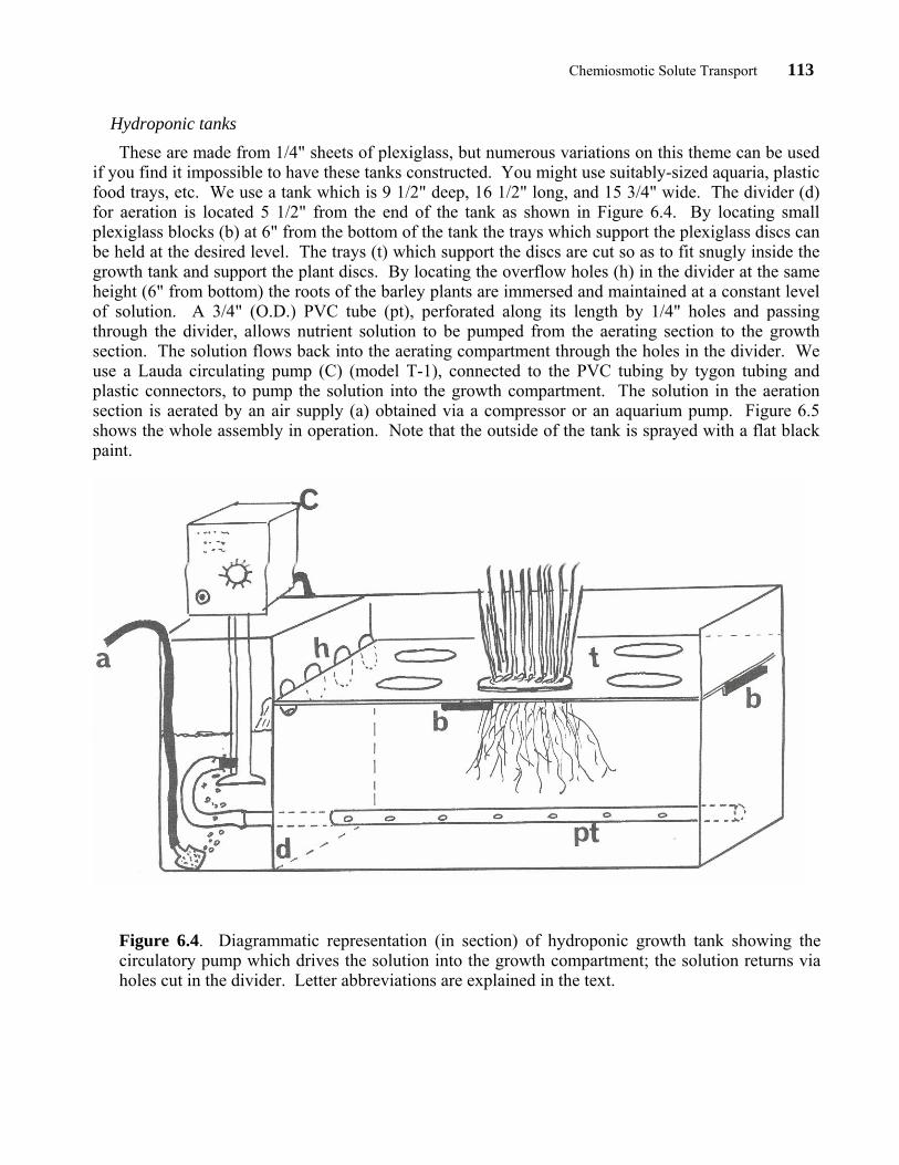
Hydroponic tanks These are made from 1/4" sheets of plexiglass, but numerous variations on this theme can be used
if you find it impossible to have these tanks constructed. You might use suitably-sized aquaria, plastic food trays, etc. We use a tank which is 9 1/2" deep, 16 1/2" long, and 15 3/4" wide. The divider (d) for aeration is located 5 1/2" from the end of the tank as shown in Figure 6.4. By locating small plexiglass blocks (b) at 6" from the bottom of the tank the trays which support the plexiglass discs can be held at the desired level. The trays (t) which support the discs are cut so as to fit snugly inside the growth tank and support the plant discs. By locating the overflow holes (h) in the divider at the same height (6" from bottom) the roots of the barley plants are immersed and maintained at a constant level of solution. A 3/4" (O.D.) PVC tube (pt), perforated along its length by 1/4" holes and passing through the divider, allows nutrient solution to be pumped from the aerating section to the growth section. The solution flows back into the aerating compartment through the holes in the divider. We use a Lauda circulating pump (C) (model T-1), connected to the PVC tubing by tygon tubing and plastic connectors, to pump the solution into the growth compartment. The solution in the aeration section is aerated by an air supply (a) obtained via a compressor or an aquarium pump. Figure 6.5 shows the whole assembly in operation. Note that the outside of the tank is sprayed with a flat black paint.
Figure 6.4. Diagrammatic representation (in section) of hydroponic growth tank showing the circulatory pump which drives the solution into the growth compartment; the solution returns via holes cut in the divider. Letter abbreviations are explained in the text.
Chemiosmotic Solute Transport 114
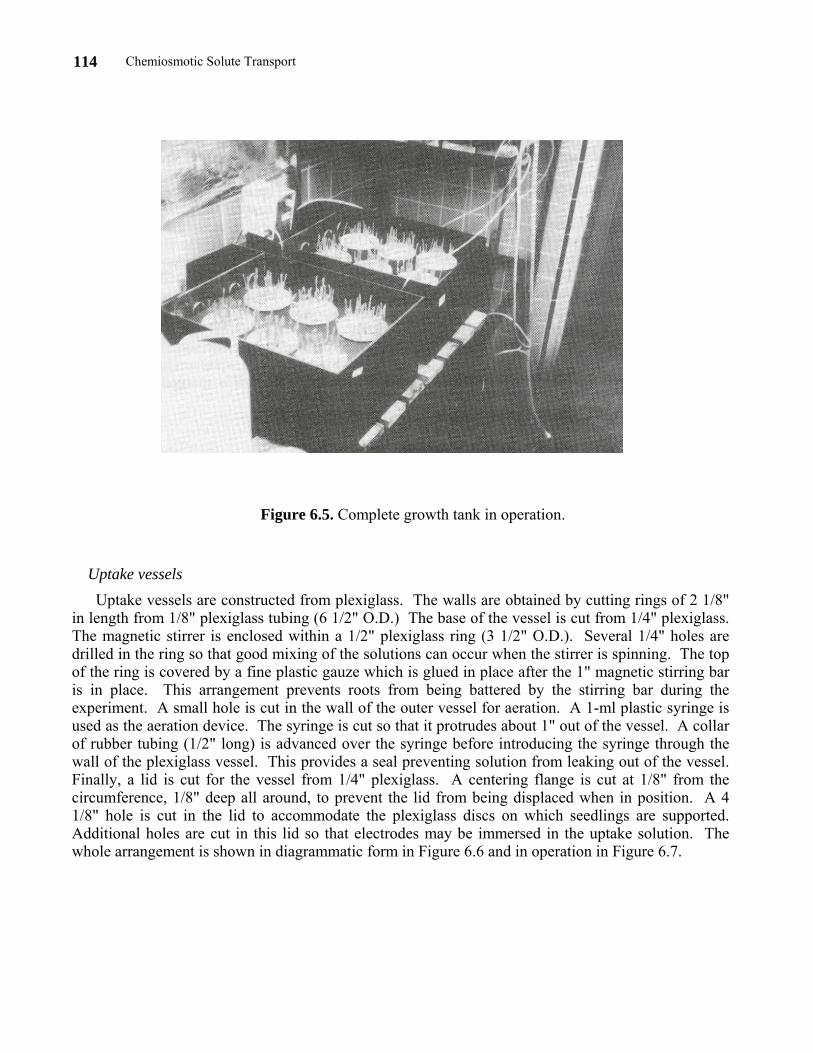
Figure 6.5. Complete growth tank in operation.
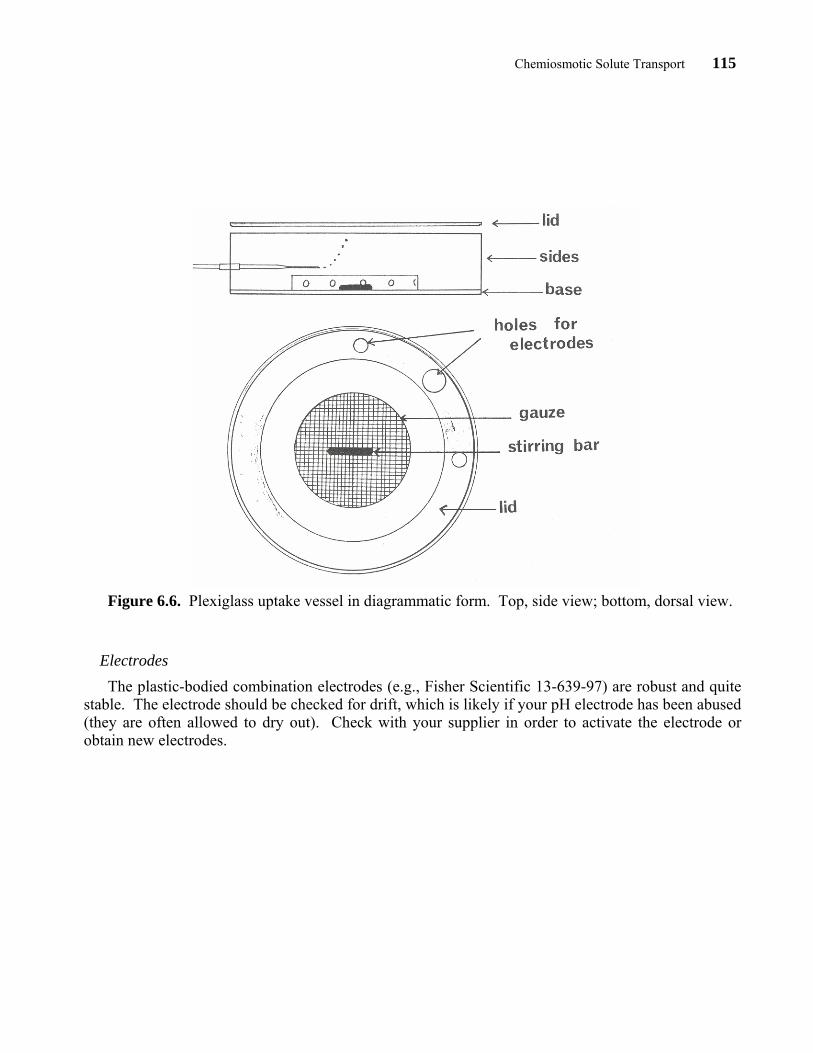
Uptake vessels Uptake vessels are constructed from plexiglass. The walls are obtained by cutting rings of 2 1/8"
in length from 1/8" plexiglass tubing (6 1/2" O.D.) The base of the vessel is cut from 1/4" plexiglass. The magnetic stirrer is enclosed within a 1/2" plexiglass ring (3 1/2" O.D.). Several 1/4" holes are drilled in the ring so that good mixing of the solutions can occur when the stirrer is spinning. The top of the ring is covered by a fine plastic gauze which is glued in place after the 1" magnetic stirring bar is in place. This arrangement prevents roots from being battered by the stirring bar during the experiment. A small hole is cut in the wall of the outer vessel for aeration. A 1-ml plastic syringe is used as the aeration device. The syringe is cut so that it protrudes about 1" out of the vessel. A collar of rubber tubing (1/2" long) is advanced over the syringe before introducing the syringe through the wall of the plexiglass vessel. This provides a seal preventing solution from leaking out of the vessel. Finally, a lid is cut for the vessel from 1/4" plexiglass. A centering flange is cut at 1/8" from the circumference, 1/8" deep all around, to prevent the lid from being displaced when in position. A 4 1/8" hole is cut in the lid to accommodate the plexiglass discs on which seedlings are supported. Additional holes are cut in this lid so that electrodes may be immersed in the uptake solution. The whole arrangement is shown in diagrammatic form in Figure 6.6 and in operation in Figure 6.7.
Chemiosmotic Solute Transport 115
Figure 6.6. Plexiglass uptake vessel in diagrammatic form. Top, side view; bottom, dorsal view.
Electrodes The plastic-bodied combination electrodes (e.g., Fisher Scientific 13-639-97) are robust and quite
stable. The electrode should be checked for drift, which is likely if your pH electrode has been abused (they are often allowed to dry out). Check with your supplier in order to activate the electrode or obtain new electrodes.
Chemiosmotic Solute Transport 116
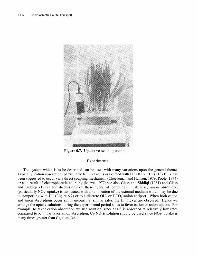
Figure 6.7. Uptake vessel in operation.
Experiments
The system which is to be described can be used with many variations upon the general theme. Typically, cation absorption (particularly K + uptake) is associated with H + efflux. This H + efflux has been suggested to occur via a direct coupling mechanism (Cheeseman and Hanson, 1979; Poole, 1974) or as a result of electrophoretic coupling (Marré, 1977; see also Glass and Siddiqi (1981) and Glass and Siddiqi (1982) for discussions of these types of coupling). Likewise, anion absorption (particularly NO3- uptake) is associated with alkalinization of the external medium which may be due to symporting with H + (Figure 6.2) or to a discrete OH- or HCO3
-/anion antiport. When both cation and anion absorptions occur simultaneously at similar rates, the H + fluxes are obscured. Hence we arrange the uptake solutions during the experimental period so as to favor cation or anion uptake. For example, to favor cation absorption we use solution, since SO4
2- is absorbed at relatively low rates compared to K +. To favor anion absorption, Ca(NO3)2 solution should be used since NO3- uptake is many times greater than Ca2+ uptake.
Chemiosmotic Solute Transport 117
Basic Experiment: K +/H + Exchange
Prepare 2 liters of 0.5 mM CaSO4 plus 0.25 mM K2SO4 solution. Check the pH of the solution and adjust (if necessary) to about 5.3 with dilute H2SO4 or Ca(OH)2 solutions. Place 1 liter of this solution in the uptake vessel and monitor the pH for at least 10 minutes. If there is drift, its extent should be noted as a function of time. Plants (on the plexiglass discs) should be pretreated for 10 minutes in this solution before undertaking the actual measurement of pH changes. This prevents massive pH changes due to transfer of solution adhering to the roots.
After the 10 minute pretreatment, transfer the plants to a second uptake vessel filled with the second liter of uptake solution. Make sure the solution is aerated and stirred. Note the pH immediately before and after transferring the plants and continue to note the pH every 5 minutes for about 30 minutes. Typically, we find substantial pH changes in this time period associated with K2SO4 provision. Students can use 0.5 mM CaSO4 (without K2SO4) as a control and check the extent of pH changes. By weighing the roots at the end of the experiment and noting the total pH changes the flux of H +, expressed as µmol H + g-1h-1, can be obtained (see Appendix B). This basic experiment can be extended and elaborated according to the available facilities.
Suggested Variations
1. Connect the pH meter to a chart recorder and monitor changes continuously.
2. Use a K+-specific electrode (Orion) with a second pH meter to simultaneously monitor changes of K+ and H+ concentration (see Glass and Siddiqi, 1981).
3. Use 0.5 mM Ca(NO3)2 instead of K2SO4 and note the alkalinization of media.
4. Examine the pH dependence of the H + fluxes by adjusting the initial pH values of a 0.5 mM K2SO4 solution in the range from 4–8 using H2SO4 or Ca(OH)2.
5. Explore the metabolic dependence of the H+ fluxes using inhibitors of metabolism. Care should be taken that the inhibitor per se has no strong effect upon pH. Dinitophenol (10-4 M) or sodium vanadate (20 µM) provide useful examples. The latter compound has been widely employed in recent research studies as it is an inhibitor of ATPase activity.
6. Use different potassium salts (e.g., KNO3, KCl, K2SO4, together with 0.5 mM CaSO4) to evaluate the effect of the rates of anion absorption on observed H+ fluxes. Similarly, the cation associated with NO3- (Ca, K, Na, Li) may be varied.
7. Use the standard K2SO4 experiment and vary temperature. I have observed that the Q10 values for H + efflux and K + uptake are extremely similar (Glass and Siddiqi, 1982).
Example of an Advanced Experiment
Using a flame photometer to monitor K + depletion from a solution containing 0.1 mM K2SO4 and 0.5 mM CaSO4, students enrolled in our Introductory Biology Program measured H + fluxes and K+
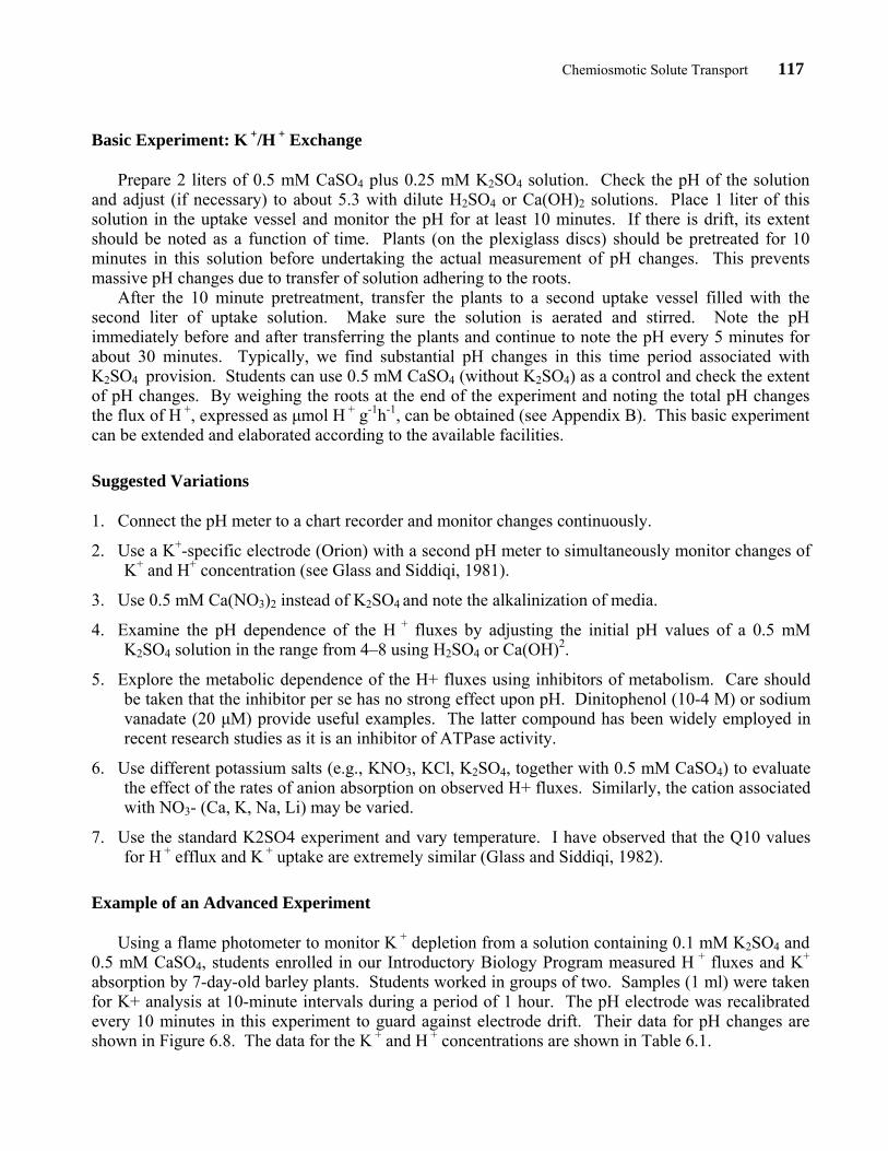
absorption by 7-day-old barley plants. Students worked in groups of two. Samples (1 ml) were taken for K+ analysis at 10-minute intervals during a period of 1 hour. The pH electrode was recalibrated every 10 minutes in this experiment to guard against electrode drift. Their data for pH changes are shown in Figure 6.8. The data for the K + and H + concentrations are shown in Table 6.1.
Chemiosmotic Solute Transport 118
Figure 6.8. Student data of pH changes associated with K + uptake by barley plants. Samples of solution (1 ml) were taken every 10 minutes and analyzed by flame photometry for K+ concentration. The pH electrode was recalibrated immediately prior to taking the samples for K+ analysis and the pH determined by dipping the electrode directly into the uptake solution.
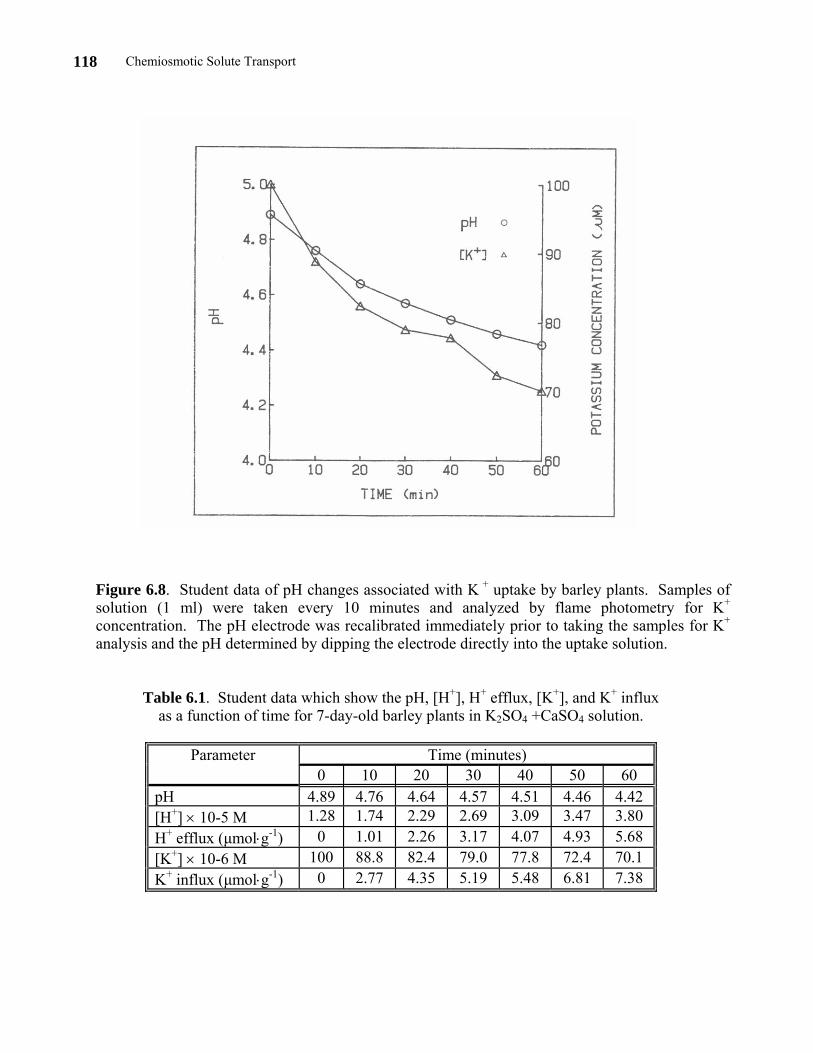
Table 6.1. Student data which show the pH, [H+], H+ efflux, [K+], and K+ influx as a function of time for 7-day-old barley plants in K2SO4 +CaSO4 solution.
Parameter Time (minutes)
0 10 20 30 40 50 60 pH 4.89 4.76 4.64 4.57 4.51 4.46 4.42 [H+] × 10-5 M 1.28 1.74 2.29 2.69 3.09 3.47 3.80 H+ efflux (µmol⋅g-1) 0 1.01 2.26 3.17 4.07 4.93 5.68 [K+] × 10-6 M 100 88.8 82.4 79.0 77.8 72.4 70.1 K+ influx (µmol⋅g-1) 0 2.77 4.35 5.19 5.48 6.81 7.38
Chemiosmotic Solute Transport 119
Literature Cited
Cheeseman, J. M., and J. B. Hanson. 1979. Energy-linked potassium influx as related to cell potential in corn roots. Plant Physiology, 69:842–845.
Churchill, K. A., and H. Sze. 1983. Anion-sensitive, H+-pumping ATPase in membrane vesicles from oat roots. Plant Physiology, 71:95–107. An example of a more molecular approach to H+ pumping ATPases of the plasma membrane and tonoplast—ideal as a more biochemical project for a senior student.
Epstein, E. 1972. Mineral nutrition of plants: Principles and perspectives. Wiley, New York. Source of information on the composition of inorganic nutrient media, particularly Johnson's modified medium (page 39).
Glass, A. D. M., and M. Y. Siddiqi. 1981. Potassium-hydrogen ion exchange across barley roots: An introduction to chemiosmotic principles of solute transport. Journal of Biological Education, 15:289–393. An introduction to the topic as well as suggestions for experiments.
———. 1982. Cation-stimulated H+ efflux by intact roots of barley. Plant, Cell and Environment, 5:385–393. Outline of mechanisms of K+/H+ exchange, the experimental basis for proposed mechanisms, characteristics of the exchange in barley and some questions concerning current models for coupling.
Hinckle, P. C., and R. E. McCarty. 1978. How cells make ATP. Scientific American, 238:104–122. An excellent introduction to the chemiosmotic hypothesis.
Marré, E. 1979. Fusicoccin: A tool in plant physiology. Annual Review of Plant Physiology, 30:273–288.
Mitchell, P. 1961. Coupling of phosphorylation to electron and hydrogen transfer by a chemiosmotic type of mechanism. Nature, 191:144–148. The right stuff! Direct from the author himself.
Nicholls, D. G. 1982. Bioenergetics: An introduction to the chemiosmotic theory. Academic Press, London/New York, 190 pages. A first class textbook which provides a concise development (in some detail) of the issues introduced in the Scientific American paper by Hinkle and McCarty (1978).
Poole, R. J. 1974. Ion transport and electrogenic pumps in storage tissue cells. Canadian Journal of Botany, 52:1023–1028.
———. 1978. Energy coupling for membrane transport. Annual Review of Plant Physiology, 29:437–460.
Smith, F. A., and J. A. Raven. 1976. H+ transport and regulation of cell pH (Chapter 12). Pages 317–346, in Encyclopedia of plant physiology (New Series), Volume IIA (U. Lüttge and M. G. Pittman, Editors). Springer-Verlag, New York. The introductory section of this chapter and the references therein provide an excellent coverage of the concepts of coupled solute transport.
Chemiosmotic Solute Transport 120
APPENDIX A Composition of Johnson's Modified Nutrient Solution
The following recipe is for 1X Johnson's medium. This medium must be provided at 1/100
strength to obtain plants which are low in inorganic ion content. We do not find it necessary to add micronutrients for the short duration of plant growth. KNO3 6 mM Ca(NO3)2⋅4H2O 4 mM NH4H2PO4 2 mM MgSO4⋅7H2O 1 mM
APPENDIX B Conversion of pH Changes to H+ Fluxes
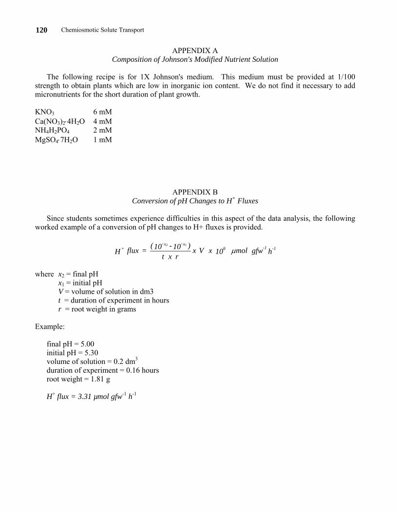
Since students sometimes experience difficulties in this aspect of the data analysis, the following
worked example of a conversion of pH changes to H+ fluxes is provided.
h gfw mol 10 x V x r x t
)10 - 10( = flux H 1-1-6x-x-
+12
µ
where x2 = final pH x1 = initial pH V = volume of solution in dm3 t = duration of experiment in hours r = root weight in grams Example: final pH = 5.00 initial pH = 5.30 volume of solution = 0.2 dm3 duration of experiment = 0.16 hours root weight = 1.81 g H+ flux = 3.31 µmol gfw-1 h-1