checking (modern) headlight systems - testek · lights (xenon, led, matrix led and laser lamps) 75%...
TRANSCRIPT

4-2-2020
5
CHECKING (MODERN)
HEADLIGHT SYSTEMS Final report
Chris Bosch & David Bulava RDW in collaboration with TESTEK

Chris Bosch (RDW) Checking (Modern) Headlight Systems David Bulava (TESTEK) 1
Name Intern Chris Bosch [email protected]
David Bulava
University Rotterdam University of Applied Sciences (Hogeschool Rotterdam)
Slovak University of Technology in Bratislava
Study Automotive Engineering Mechanical Engineering
Supervisor Arthur van Lee Piet Schäfer
Juraj Matej
Company RDW Europaweg 205 2700 AT Zoetermeer Netherlands
TESTEK Vajnorská 1347/137, 831 04 Bratislava Slovakia
Date 4-2-2020 Version: 1.0

Chris Bosch (RDW) Checking (Modern) Headlight Systems David Bulava (TESTEK) 2
Index 1. Introduction ..................................................................................................................................... 4
2. Management summary ................................................................................................................... 6
3. Theme .............................................................................................................................................. 7
4. Issue ................................................................................................................................................. 7
5. Main question.................................................................................................................................. 8
6. Sub question .................................................................................................................................... 8
7. Theoretical framework .................................................................................................................... 9
1. Acetylene/oil lamps ..................................................................................................................... 9
2. Electric lamps .............................................................................................................................. 9
1. Sealed beam ............................................................................................................................ 9
2. Halogen lamps ....................................................................................................................... 10
3. Projector headlamps ................................................................................................................. 11
4. Xenon (HID) ............................................................................................................................... 11
5. LED ............................................................................................................................................. 12
6. Matrix LED ................................................................................................................................. 14
7. Laser headlamps ........................................................................................................................ 15
8. Adaptive Front-lighting Systems (AFS) ...................................................................................... 16
9. Headlight aiming........................................................................................................................ 17
8. Current situation ........................................................................................................................... 18
1. The Netherlands ........................................................................................................................ 18
2. Slovakia ...................................................................................................................................... 21
3. ECE regulations .......................................................................................................................... 23
9. Delineation .................................................................................................................................... 24
10. Results ....................................................................................................................................... 25
1. What factors have an influence on the adjustment of the headlight? ..................................... 25
1. What is the influence of a deviation in the floor compared to horizontal longitudinal axis
and horizontal width axis of the vehicle on the adjustments of the headlights? ......................... 25
2. What is the influence of the tire pressure on the dipped beam adjustment?...................... 29
3. What is the influence of the position of the steering wheel on the dipped beam
adjustment?................................................................................................................................... 36
4. What is the influence of the position of a vehicle lift in the lowest position, in a lock,
hanging in the cables? ................................................................................................................... 37
5. What is the effect of bending a vehicle lift by a vehicle that’s on it? ................................... 39
6. Does the ambient lighting of the test location influence the light image and the horizontal
cut-off line produced by the (adaptive) headlight? ...................................................................... 41

Chris Bosch (RDW) Checking (Modern) Headlight Systems David Bulava (TESTEK) 3
2. What is the influence of damage (scratches, breaks or discoloration) of the windshield on
sensors or cameras? .......................................................................................................................... 41
3. Is it possible to check modern lights (eg. LED and Adaptive) pursuant Directive 2014/45 /EU
with analog test equipment? ............................................................................................................ 41
1. Is the result of a test on an analog test equipment reproducible on a digital test
equipment? ................................................................................................................................... 42
4. Should we (in the future) check the operation of adaptive lighting in the PTI? ....................... 43
1. Are adaptive lights easy to check during the PTI? ................................................................. 44
2. Is connecting to the OBD necessary, for example, with adaptive dipped beam? ................ 44
3. What are the most common actions for checking adaptive light? ....................................... 44
4. In the future, will we need information from importers / manufacturers for checking the
dipped beam? ................................................................................................................................ 44
5. Should the dipped beam be checked in the basic setting? ................................................... 45
5. When does the automatic dipped beam control of a vehicle start to work, e.g. only driving,
stationary. Should we also take into account during a check that the dim lamps must first be rested
after a ride? ....................................................................................................................................... 45
1. Which modern lights are currently in use and which can we expect (in the short term)? ... 45
11. Discussion .................................................................................................................................. 49
12. Conclusion ................................................................................................................................. 50
13. Recommendations..................................................................................................................... 51
14. Reverences ................................................................................................................................ 52
15. Glossary ..................................................................................................................................... 53
Sources .................................................................................................................................................. 53
Annex ..................................................................................................................................................... 59

Chris Bosch (RDW) Checking (Modern) Headlight Systems David Bulava (TESTEK) 4
1. Introduction This project started in a CITA group in Brussels. Some members of the CITA group wanted to research
the modern headlamp systems (hence the name of this report). TESTEK (Slovakia) and the RDW
(Netherlands) agreed to find a student and describe an internship assignment together. TESTEK and
RDW are for their countries the controlling company for the PTI. Later both the RDW and TESTEK found
a student and started the internship. Additionally, the RDW noticed that the current Dutch PTI
requirements are from a couple decades ago and haven’t changed much since. So can these
regulations still be used with modern LED and/or adaptive headlamps.
In the late 19th century lights came to automobiles.
Not for the driver to see but for other road users to
notice the vehicle on the road. Back then candles
and oil lamps were used on the automobiles. In the
start of the 1900’s as the speeds on the roads
increased the acetylene lamp made an entrance so
that not only other drivers could see the car, the
driver could actually see the road he or she was
driving on. A carbide lamp illuminates the road with
a bright white light which makes it suitable as a
headlamp.
Electric lights were invented in 1879 by Thomas Edison but the electric headlamps didn’t become
available until 1919. The problem was a power source for these headlamps. There was no alternator
that could fit in the car and produced enough power yet. After such an alternator was invented, the
electric lights became available. The first electric lights used filament of carbon which only had a
lifespan of 40 hours and the light output was very limited. In 1920 the carbon wire was replaced by a
tungsten wire which improved the lifespan to 1500 hours. That made them more usable in cars and
around that time they were introduced in cars. At first, as with the acetylene lamps, the lamps were
separate units on top of the body of the car. 10 years later, in the 1930’s, car designers started to
implement the lamps into the body.
As with carbide lamps, the new electric filament lamps had the problem of blinding the oncoming
traffic. This was somewhat fixed by using a parabolic reflector and a lens. In 1924 the Bilux/Duplo lamp
was invented. This lamp had 2 filaments with one for dipped beam and one for main beam. The
filament for dipped beam was partially covered and aimed at the road 80m away. This meant that
oncoming traffic wasn’t blinded by the headlamps. The filament used for main beam wasn’t covered
at all and lit the complete road over a distance of 150m. This light was blinding for oncoming traffic
and that’s why a law was introduced to only allow main beam with no oncoming traffic.
In 1940 the sealed beam headlamp was
introduced in America to create a
standardized headlamp in all passenger
cars. This was a closed unit with a
filament wire, a lens and reflector with
a standard size build in. This light was
mandatory by law in the US. 20 years
later, in the 1960’s these lamps made
their way into Europe and Japan.
Figure 1. Acetylene lamp
Figure 2. Sealed Beam headlight

Chris Bosch (RDW) Checking (Modern) Headlight Systems David Bulava (TESTEK) 5
The sealed beam headlamps didn’t stay long because the interchangeable halogen lamps came to
Europe in the 70’s. Mostly the Duplo interchangeable H4 halogen lamps with 2 filaments for dipped
and main beam were very popular because of the long lifespan and high light output.
HID lamps (High Intensity Discharge also known as xenon lamps) became popular in the start of the
21st century and after that were very popular as aftermarket bulbs for filament halogen lamps.
LED lamps were introduced in early 60’s. At first when LED lamps came to cars in 1993, it was used as
a 3rd brake light or rear lights. From 2004 it was introduced as headlamps and daytime running lights.
LED lamps tend to have a longer lifespan and higher light output than traditional halogen lamps. Also
with multiple individual LEDs being used to create dipped or main beam as in matrix LED lights new
lighting solutions can be created like ‘’glare free high beam’’.
Figure 3. Audi Matrix LED lamp

Chris Bosch (RDW) Checking (Modern) Headlight Systems David Bulava (TESTEK) 6
2. Management summary Some members of the CITA group wanted to research the modern headlamp system and both RDW
and TESTEK found a student for an internship. The main question of this study is how the current PTI
requirements concerning headlights systems can be revised.
A couple of factors have influence on the correct adjustment of the headlamps:
- Deviation in the floors of test location
- Steering wheel angle of the test vehicle
- Tire pressure of the test vehicle
These factors were tested at Explora in the Netherlands and at Homola in Slovakia. The steering wheel
angle hasn’t got any influence on the adjustment of the headlamp on most vehicles. A deviation in the
floor or the tire pressure does have an influence on the inclination. This proves the importance of
having a completely flat floor and the by the manufacturer recommended tire pressure in the tires
during checking and adjusting the headlamps. In some workshops the inclination of the headlamp is
tested on the vehicle lift. An effect of the different positions and the bending of the vehicle lift was
tested at a RDW station. The results show that the different positions of the lift have an effect. If
adjusting the headlamps do this in the lowest position (when lift is basically on the floor) or when it is
in a lock. While the test proved that the lift at the RDW station is the most level when hanging in the
cables, the adjusting if done on a lift should be in a lock or the lowest position. These positions can
easily be adjusted to make the lift completely level. An even more crucial point is that the floor where
the headlight tester is standing on, should be in the same plane as the lift otherwise it wouldn’t matter
whether the lift is level or not.
The guideline 2014/45/EU describes the modern PTI.
But the current PTI and the guideline doesn’t talk
about the adaptive lights. More and more adaptive
light have come available and this will keep growing.
There are already 36 manufacturers that offer
‘’modern’’ headlamps. Currently from all the modern
lights (Xenon, LED, Matrix LED and Laser lamps) 75%
is equipped with some sort of AFS feature. Some
examples of such a AFS feature are Automatic High
Beam, Adaptive high beam or glare free high beam,
reduce glare from traffic signs, Adverse weather light,
Dynamic bend light, Town/city light and
Country/motorway light.
These systems are getting available in more affordable cars and more drivers use them. That is why in
the future PTI we should check them. Checking the headlamps isn’t going to be a less than 5 min job.
With the ‘modern’ headlamps checking them is more complicated. For adjusting and checking the
headlamps every manufacturer has a different method. With almost every modern lamp a digital
headlight tester should be used. It is possible to use an analog tester but it is questionable whether it
is done right then. As well as using a digital headlamp tester, an OBD device should also be used to
initiate the test mode. For a PTI technician to correctly do all this, he or she will need information from
the manufacturer specifying the correct inclination for the concerned vehicle, where the centre point
of the beam is, how to initiate the test mode with the complete checking and adjusting procedure and
with what OBD device and headlamp tester.
Figure 4. Adaptive High Beam

Chris Bosch (RDW) Checking (Modern) Headlight Systems David Bulava (TESTEK) 7
3. Theme The theme of this report is blinding headlamps. Drivers experience blinding headlights every day on
the road. A lot of people on the road blame the new LED headlamps because of the high intensity of
the light. A Dutch motoring organisation (ANWB) recently published a report about this theme.
Blinding headlamps can have a couple of causes. One, some modern xenon or LED headlamp are too
bright even in dipped beam or as daytime running lights. The study mentions that they found that a
daytime running light that was 3 times as bright as a direct look into the sun. This is because a daytime
running light has to been seen even on a very sunny day although on other days this can create glare
for other road users. One of the characteristics of a LED lamp is that the light has a higher colour
temperature which translate into a ‘’colder’’ colour that is more like daylight, a more blue like light. In
contrast with halogen lamps which illuminates with a ‘warmer’ light. This type of bluish light is less
comfortable for the eye which contributes in the blinding effect. Another characteristic of LED lamps
is that there is a very sharp cut-off line which also doesn’t help with decreasing the blinding effect.
Two, the adjustment can be wrong. There are a lot of cars with wrong adjustment on the road.
There is also a difference between being blinded by a headlight and being annoyed by a headlight.
Most of the time when people think they’re being blinded by a bright headlight is that they are just
being annoyed by it and not blinded. An annoyed driver is still a more dangerous driver than a calm
one but in comparison with a blinded driver is it less dangerous. An annoyed driver will behave less
cautious on the road than a calm one which results in a high chance of a crash or collision. A blinded
driver means that he or she has no vision for a short period which can create an unsafe situation and
an even higher chance of a crash or collision. Also being blinded is an even bigger safety problem with
older drivers or drivers with prescription glasses and/or other eye conditions.
4. Issue The main issue is if PTI stations in the future can still check the function and the adjustment of the
headlights and if they can do this correctly. A lot of the modern LED headlamps are too complicated
for a non OEM mechanic or PTI inspector to check if they work properly. Also the current Dutch PTI
instruction doesn’t talk about adaptive front lighting systems. This can create unsafe situations on the
road in which incorrectly adjusted headlamps or incorrectly working adaptive headlamps can be the
cause.
With modern adaptive LED headlamps there is another problem that the basic dipped beam is used
when testing or adjusting because the regulations are based around it. This is because of the past when
dipped beam was mostly used. But most of these adaptive lamps have different light images for roads
in town, out of town and on the highway and are not based around the dipped beam but around the
main beam. Also the cut-off lines are different between these lamps due to different types of type-
approval. This can cause problems at the PTI.

Chris Bosch (RDW) Checking (Modern) Headlight Systems David Bulava (TESTEK) 8
5. Main question The main question of this report is:
How does the current PTI requirements concerning headlight systems have to be
revised and what can be improved?
6. Sub question The main question is tested using sub questions. Some sub questions can be divided in more sub
questions.
1. What factors have an influence on the adjustment of the headlights?
1. What is the influence of a deviation in the floor compared to horizontal longitudinal
axis and horizontal width axis of the vehicle on the adjustments of the headlights?
2. What is the influence of the tire pressure on the dipped beam adjustment?
3. What is the influence of the position of the steering wheel on the dipped beam
adjustment?
4. What is the influence of the position of a vehicle lift:
i. In the lowest position?
ii. In a lock?
iii. Hanging in the cables?
5. What is the effect of bending a vehicle lift by a vehicle that’s on it?
6. Does the ambient lighting of the test location influence the light image and the
horizontal cut-off line produced by the (adaptive) headlight?
2. What is the influence of damage (scratches, breaks or discoloration) of the windshield on
sensors or cameras?
3. Is it possible to check modern lights (eg. LED and Adaptive) pursuant Directive 2014/45/EU
with analog test equipment?
1. Is the result of a test on an analog test equipment reproducible on a digital test
equipment?
4. Should we (in the future) check the operation of adaptive lighting in the PTI?
1. Are adaptive lights easy to check during the PTI?
2. Is connecting to the OBD necessary, for example, with adaptive dipped beam?
3. What are the most common actions for checking adaptive light?
4. In the future, will we need information from importers / manufacturers for checking
the dipped beam?
5. Should the dipped beam be checked in the basic setting?
5. When does the automatic dipped beam control of a vehicle start to work, e.g. only driving,
stationary. Should we also take into account during a check that the dim lamps must first be
rested after a ride?
1. Which modern lights are currently in use and which can we expect (in the short
term)?

Chris Bosch (RDW) Checking (Modern) Headlight Systems David Bulava (TESTEK) 9
7. Theoretical framework In the theoretical framework some important subjects around headlamps are explained.
1. Acetylene/oil lamps The first ever lights that were used in vehicles
created light by burning acetylene (C2H2).
Acetylene is the result of a reaction between
calcium carbide (CaC2) and water (H2O). The
lamp usually had a mirror behind a frame to
help focus the light forwards. At first the lamps
were used to illuminate the vehicle for other
road users. Later the lamps were used to light
the road. These lamps existed for a long time
already and were used in mines or to light
buildings. These lamps were pushed away by
electric lights with filament in the 1900’s.
The acetylene (carbide) lamp shines bright white light. The lamp consists of the light unit and a tank
with 2 chambers with carbide and water. A valve controls the amount of water drops that flows into
the carbide chamber. With a gasline the produced acetylene gas flows to the light unit. The gas is
lighted with a firestone or a match.
2. Electric lamps Most electric lamps use a filament. The filament is made of materials which are good conductors like
tungsten or carbon. The first electric lights used a carbon filament, but this was later replaced with
tungsten due to the short lifespan of carbon filament lights. When the lamps are turned on, electricity
flows through it and the conductor heats up. If enough electricity is used, the filament will glow red or
white hot and give out light. A big problem with filament lights is that it produces a lot more heat than
light. These lamps also aren’t filled with air but with an inert gas so that the filament itself won’t start
to burn. This improves the lifespan of the lamp. Though even with this gas the filament still burns up
slowly.
1. Sealed beam Sealed beam units were introduced in the United
States with the goal to create a standardized
headlamp for all passenger cars. In this lamp is the
lens, the reflector and the filament placed and
sealed in one unit. This provided a more focused,
brighter light source for cars which was the same
for all cars. The downside was that they use a lot of
power for the amount of light it produced. Also the filament can leave dark residue on the glass of the
sealed beam which creates a dark spot where light can’t go through.
Figure 6. Sealed beam lamps
Figure 5. Acetylene lamp

Chris Bosch (RDW) Checking (Modern) Headlight Systems David Bulava (TESTEK) 10
In the sealed beam units a parabolic reflector is used
which is a curved mirror that focuses the light
towards one place. The light shines into the reflector
at which it is bounced off at a specific angle. The
reflector together with a cap around the bulb
ensures the light shines downwards.
The sealed beam lamps had cover lenses with
dispersion optics which were used to scatter or focus
the light. Such cover lens is on the previous page in
the bottom. This cover lens is also used to create the
cut-off line.
2. Halogen lamps Halogen lamps are similar to normal filament lamps with the difference that they glow hotter and
brighter. In a normal filament lamp the filament is made of tungsten and have inert gas around it. The
gas in halogen lamps are usually iodine or bromine. Halogen lamps are also known as Quartz Iodine
lamps and are the most used lights in the auto industry at nowadays due to the low costs. The high-
temperature quartz glass allows a much higher temperature for the filament which means a higher
light output. The high temperature quartz glass is made out of Silica glass. Silica glass is sensitive to dirt
and grease, so it is not recommended to touch it directly during placing the bulb. Halogen are marked
with the letter H.
The reason halogen lamps have a longer
lifespan than more traditional filament
lamps is the way halogen gas reacts with
tungsten. These halogen gasses constantly
regenerates the tungsten filament. As the
lamp burns the tungsten is slowly
vaporized. When it comes free from the
filament and reacts with the halogen it
creates tungsten halide gas. This halide gas
moves around until it comes close to the
hot filament at which it splits apart and
creates tungsten back on the filament. Thanks to this phenomenon, halogen lamps are up to twice as
efficient as the classic bulbs.
Later in further development the Duplo lamp was made. This lamp had 2 filaments, one for dipped
beam and the other for main beam. This got very popular very quickly due to the longer lifespan and
higher light output.
As headlamps got developed further and further and
car body’s got more aerodynamic, so did headlamps.
Headlamps got more aerodynamic housings to be able
to create more aerodynamic efficient cars. Also clear
cover lenses were used and the cut-off line is now
produced by the horizontally arranged reflector
segments as seen in the figure shown on the right here.
Figure 8. Quartz Iodine lamp
Figure 7. Parabolic reflector
Figure 9. Creating the cut-off line

Chris Bosch (RDW) Checking (Modern) Headlight Systems David Bulava (TESTEK) 11
3. Projector headlamps In projector headlamps, a different
construction was used. As with most
headlamps a reflector is used. For the cut-
off line a shutter is used. The shutter can be
raised or lowered to create main or dipped
beam. Also, a projector headlamp uses an
elliptical reflector instead of a parabolic
one. The reason for this different reflector is
because an elliptical reflector focuses on
one narrow point and aims the light beam
more effectively on the road. A projector
headlamp can be used with halogen bulbs
or xenon and LED lamps. The lens is also an
important part of the construction. It is designed to evenly distribute the light beam. Some projector
headlamps also use the lens to create a softer cut-off line.
4. Xenon (HID) HID (high intensity discharge) lamps are
different than traditional halogen lamps by
using xenon gas instead of halogen gas. Xenon
is a noble gas. A noble gas is a chemical
element which is generally clear and very
stable under the typical atmospheric
conditions. Instead of emitting light by
electrical resistance passing through a
filament in halogen bulbs, in HID lamps there
is no filament. The chamber is filled with
xenon gas and two electrodes. The gas emits
the lights when the electrical jump happens
between two electrodes. Xenon headlamps
are made of the following parts:
Gas discharge lamp
Xenon ballast
Ignition module
Reflection and projector-type system
The gas discharge lamp is the bulb and it contains the xenon gas. This is the part, which emits the light
itself. Xenon ballast is a device that ignites the inert gaseous mixture inside the bulb. The latest xenon
systems pulse up to 40kV. This part controls the bulb start-up, allowing to reach the operating phase
quickly. It also controls the constant power to 35W. the ignition module is connected to the xenon
ballast and it delivers the spark into the xenon light module. It can contain metal shielding too.
There are several advantages using HID in comparison with the conventional halogen headlamps. A
HID lamp produces 3000 lumens, which is more than 50% more than 1400 lumens from halogen bulb.
The color temperature of the light from the xenon bulb is more natural, with about 4000 to 6000K it is
similar to a day light. Halogen headlamps produces more yellow light. The HID also has wider range of
illumination, same as a longer illumination down the road. This fact secures more safety on the roads.
Figure 10. Projector headlamp
Figure 11. Xenon headlamp module

Chris Bosch (RDW) Checking (Modern) Headlight Systems David Bulava (TESTEK) 12
5. LED For LED lamps, the light source is a luminescent
LED. LED stands for “light emitting diode”. It
turns electrical energy into light. The LED emits
light by means of a semiconductor component
when an electric current flows through the LED
in the flow direction, it means from anode (+) to
cathode (-). The semiconductors are materials,
which are not conductive in itself. But when it is
supplied with energy, for example electric
energy, it can become conductive. For a
semiconductor silicon, germanium, selenium or
certain salts are used. The layers of
semiconductor form the LED chip. The LED chip
consists of these parts:
Resin lens
Gold wire (contact to anode)
LED chip
Reflector tray (contact to cathode)
Figure 12. Difference between halogen and HID (xenon) lights
Figure 13. LED lamp

Chris Bosch (RDW) Checking (Modern) Headlight Systems David Bulava (TESTEK) 13
The n-doped layer is prepared by the
supplying energy to the semiconductor.
Because of this, there is excess of the
electrons. In the p-doped layer, there is very
small amount of these carriers of the
charge. This condition produces electron
holes. When a charge is than applied on
both layers, ‘’the charge carriers’’ come
closer to each other. In the middle, on the
pn junction, recombination happens. 2
oppositely-charged particles form a neutral
one. This phenomenon results in energy
release in the form of light.
At first LED’s were only used in brake lights but the lamps moved forwards later. At first the LEDs were
used, as with normal H7 halogen lamps, one LED unit with a reflector or as a projector lamp but as the
technology got better and more advanced more LEDs in started getting used to create same light
image. This created the problem that sometimes it is hard to know at which LED a headlight tester has
to be pointed at. The picture below illustrates that argument.
Also are LED headlamps much more
efficient than standard halogen lamps
which is why almost all electric cars used
LED lamps as headlamps. The colour that
the LED shines has a different colour
temperature than halogen lamps. An LED
lamp shines a much whiter light than a
halogen lamp which means a LED creates
more blinding light. Very white light has
a more blinding effect than the warmer
halogen lights.
Figure 14. Explanation of LEDs
Figure 15. Ford Focus LED headlamp

Chris Bosch (RDW) Checking (Modern) Headlight Systems David Bulava (TESTEK) 14
6. Matrix LED A further development in the LED lamps is the matrix LED lamp. As with some other LED lamps it uses
multiple LEDs. But with a matrix LED lamp not just 2 or 3 LEDs are used to create the beam. The more
LEDs a matrix LED lamp has the more precise it works. There are multiple manufacturers that offer
such systems all with a different amount of LEDs. Every matrix LED headlamps is part of an AFS system.
Not only the high end brands offer them, also more affordable brand are introducing them. For
instance Land Rover’s system uses 71 LEDs per headlamp. Opel is one of the more affordable brand to
bring matrix LED lamps to cars. Opel uses 16 LEDs per headlamp. Mercedes-Benz offers a matrix LED
system in their cars called Multibeam. This system uses 84 individual LEDs in 3 rows above each other.
This system uses a camera, radar and navigation to create very specific light beams for specific
situations.
This system can dim individual LEDs from 100% to 0% which means it can be used for all kinds of
adaptive features. One of which is what Mercedes-Benz calls Adaptive High Beam Assist Plus. The
system can detect an oncoming vehicle or a vehicle driving in front of the car and dim the individual
LED that is illuminating that vehicle. The driver of the oncoming vehicle will not be blinded now. Also
the cut-off line with this system is not created by a shutter or the reflector but by dimming the LEDs
on the upper left side. Another feature is the illumination of a junction and shine a light beam towards
the road the vehicle is indicating to go. Also the reducing glare from the reflection of traffic signs is an
feature. The camera detects the glare from the sign and dims the specific LED that is illuminating it.
More of these adaptive features will be talked about in the ‘’Adaptive Front Lightning Systems (AFS)’’.
Nowadays multiple brands offer matrix LED
systems with not only a different amount of
LEDs but also different shapes and
constructions. For instance Audi as seen in the
picture above uses an L-shape with multiple
LEDs and Mercedes uses one project lamp
housing to house multiple rows of LEDs. One of
the problems with all the different sort of
systems is, at which LED does the headlight
tester needs to be pointed at.
Figure 16. Mercedes-Benz Multibeam
Figure 17. Aiming a headlight tester

Chris Bosch (RDW) Checking (Modern) Headlight Systems David Bulava (TESTEK) 15
7. Laser headlamps Laser headlamps consists of three blue lasers emitting the beams. But the beams don´t shoot on the
road and illuminate the road ahead of the car. These beams are firing into set of mirrors, which are
concentrating the energy into the lens filled with yellow phosphorus. The lens emits the white light,
which is safe to look in directly with no danger of damaging the eyesight. This light is illuminating the
road. First time, laser headlamps were used in the BMW i8. They say that the laser headlamps can light
up to 1000 times brighter than LED headlamps and using less energy than any current technology. It
means that in future the headlamps using this technology can be built much smaller while having
better properties. The main advantage of laser headlights is the longest reach of all technologies, which
brings more visibility and safety. The light´s colour temperature is between 5500 up to 6000 Kelvin
which is near to a natural daylight with value 6500 Kelvin.
Figure 18. Mercedes-Benz's Adaptive High Beam Assist Plus
Figure 19. Laser headlamps

Chris Bosch (RDW) Checking (Modern) Headlight Systems David Bulava (TESTEK) 16
8. Adaptive Front-lighting Systems (AFS) When a vehicle is equipped with an Adaptive Front-lighting System (AFS), it can mean multiple things.
For instance, it can be a headlamp with an automatic high beam function or it can be an expansive high
end headlamp with matrix LEDs and adaptive lighting. According to ECE regulation No. 123 an adaptive
front-lighting system is ‘’a lighting device, providing beams with differing characteristics for automatic
adaptation to varying conditions of use of the passing-beam (dipped-beam) and, if it applies, the
driving-beam (main-beam) with a minimum functional content as indicated in paragraph 6.1.1; such
systems consist of the ‘system control’, one or more ‘supply and operating device(s)’, if any, and the
‘installation units’ of the right and of the left side of the vehicle’’. Paragraph 6.1.1 says that every
system must provide a ‘’class C’’ passing-beam. A ‘’class C’’ passing beam is the standard dipped beam.
Almost all AFS use a camera in the windshield to detect certain situations and adapt to them. An AFS
can have the following features:
- Automatic high beam
- Adaptive high beam or glare free high beam
- Adverse weather light
- Dynamic bend light
- Town/city light
- Country/motorway light
Automatic high beam engages the main beam if it detects no oncoming vehicles or vehicles driving
ahead that could be blinded by the main beam. It disengages if the camera detects an oncoming vehicle
Adaptive high beam takes this a step further as with the Multibeam system. It can dim oncoming
vehicles, cyclists, pedestrians from main beam. This makes more illumination possible of the road while
not blinding other road users. Adverse weather light is meant to replace the front fog lamp. The
headlamp creates a beam similar to what a fog lamp would create and ensures better illumination in
heavy weather conditions. With dynamic bend lightning the headlamps turn according to the angle of
the steering wheel and the speed. Usually the headlamps can turn 15 degrees to the left or either the
right. This illuminates long bends on dark roads better. Most brands offer this only in main beam, but
some other brands are also using it in dipped beam. City or town light is a feature used at low speeds
in town or in a build-up area. City light creates a very wide light distribution to illuminate as much as
possible in front of the vehicle. Country or motorway light is a light used in higher speeds on back roads
or on the motorway as the name suggests. This light is similar to normal dipped beam only with more
illumination on the right side on a higher distance. This creates better visibility without blinding
oncoming vehicles. All AFS’s work is specific ways which are all manufacturer specific. Some systems
might work slightly different than explained here.
Figure 20. Adverse weather light
Figure 22. Dynamic bend light (2). Normal dipped beam (1) Figure 22. City light

Chris Bosch (RDW) Checking (Modern) Headlight Systems David Bulava (TESTEK) 17
9. Headlight aiming The setup of the headlight aiming is the key for the safety on the roads. When headlamps are set too
high, you will blind other drivers. When headlamps are set too low, the driver has a limited vision of
the road. A headlight tester is used to optimally set up the headlamps. A headlight tester is a
diagnostical device intended for inspection and adjustment of every type of headlamps. It´s an optical-
mechanical device operating on the principle of direct projection of the light emitted by the headlamp.
The headlight tester represents a proportional of the set-up conditions according to the wall which is
in the distance of 10 meters. Tester works on the principle of direct projection, when the Fresnel lens
reflects light beams directly on the projection surface perpendicular to the optical axis of the
projection. But it can work also on the principle of indirect projection, where there is an inclined mirror
in the axis of the lens. The mirror reflects light beams on the projection surface. Headlight tester must
be aimed directly to the source of the light. Headlight tester must be height adjustable and the vehicle
must be parallel to the headlight tester during the measurement. But it can work also on the principle
of indirect projection, where there is an inclined mirror in the axis of the lens. The mirror reflects light
beams on the projection surface. Headlight tester must be aimed directly to the source of the light.
The headlight tester have to be around 50cm from the headlamp to give most accurate information
and also it have to be positioned on the flat surface. For the best results, the driver´s seat should be
loaded by a person or by a 75kg load. The tyres must have the air pressure prescribed by the
manufacturer.
The pitch angle is expressed by this formula:
𝐻 − ℎ
1000× 100
There are 2 types of the headlight testers:
Analog headlight tester
Digital headlight tester
In the digital tester, the projection surface is replaced
with screen and the human factor reading the values is
replaced with the digital analysis by a camera and a
computer program, which automatically evaluates the
results with the accuracy of 0,1%. The advantage of using
digital headlight tester is the accuracy of measurements
and the reproducibility of measurements. It´s also
possible that in the future, we will be able to check
modern headlights by using only digital testers with the
latest software. Figure 24- Digital headlight tester
Figure 23. Principle of the headlight tester

Chris Bosch (RDW) Checking (Modern) Headlight Systems David Bulava (TESTEK) 18
8. Current situation The PTI requirements of the Netherlands and Slovakia are shown below. These illustrate what the
requirements currently are.
1. The Netherlands In the Netherlands the current PTI requirements which are relevant for this matter are those of the
adjustment of dipped beam, article 5.2.56. This requirement is specific for the passenger cars. They
are shown below. The regulations for commercial vehicles and three-wheelers are further on in
respectively article 5.3.56 and 5.5.56.
Article 5.2.56 dipped beam adjustment
1. The dipped-beam headlamps must be adjusted correctly, in accordance with the requirements
specified in the Additional Permanent Requirements, Articles 113 and 114.
2. Passenger cars provided with a number plate containing the letter groups CD or CDJ or the
letter groups BN or GN and two groups of two digits, or an indication concerning aberrant
beam headlamps in the vehicle registration register may be equipped with dipped-beam
headlamps with an aberrant beam. This is subject to the requirements specified in the
Additional Permanent Requirements, Articles 113 and 114.
In number 2 above, the number plates with the letters CD, CDJ, BN or GN are diplomatic plates, plates
of embassies or plates of international military forces temporarily in the Netherlands which have
exemption of certain regulation. As read above the ‘Additional Permanent Requirements’ articles 113
and 114 are used. These say:
Article 113
1. The dipped-beam headlamp must be adjusted in such a way that during an inspection using a
headlamp tester or a light screen, the projected image, after fixation of this device or screen,
complies with the following requirements:
a) the illuminated area must be situated below the dark area;
b) a clear, wholly or partially horizontal dividing line must be visible between the light and
the dark area; c
c) the horizontal part of the dividing line must be situated between the lines on the screen
of the headlamp tester which correspond to a declination of the light beam of between
5 and 40 mm/m with respect to the horizontal centre line of the headlamp;
d) If a partially horizontal division line is visible:
1. The horizontal part of the dividing line must be mostly situated to the left of
the vertical centre line on the screen of the headlamp tester;
2. The intersection of the horizontal and non-horizontal part may not be situated
to the left of the vertical centre line on the screen of the headlamp tester;

Chris Bosch (RDW) Checking (Modern) Headlight Systems David Bulava (TESTEK) 19
Article 114
1. The direction of the light beam from the dipped-beam headlamps must be checked with the aid
of a headlamp tester in front of the vehicle and whereby
a) all wheels of the vehicle are in the forward driving position;
b) the handbrake of the vehicle is disengaged, and
c) the vehicle and headlamp tester are on a flat and horizontal surface.
2. If the vehicle is equipped with a unit which allows for easy adjustment of the dipped beam
setting to the load condition, this unit must be set to the position corresponding to the load
condition during the inspection.
3. If the vehicle is equipped with an automatic level adjuster, the inspection must be performed
with the engine running at idle. Any control unit must be in the normal driving position.
4. Vehicles provided with a number plate containing the letter groups CD or CDJ or the letter
groups BN or GN and two groups of digits, or an indication concerning aberrant headlamps in
the vehicle registration register or on the registration certificate may be provided with dipped-
beam headlamps with an aberrant beam. The dipped-beam headlamps is considered not to be
glaring if it is set as follows:
a) Overall, the brightest area projected, both for a laden or unladen vehicle, may not be
situated above the horizontal line which corresponds to a declination of the light beam
of 2 cm/m with respect to the centre of the headlamp;
b) In addition, the centre of this area may not be situated clearly to the left of the vertical
centre line on the screen of the headlamp tester.
The second paragraph of article 113 has been left out due to it being irrelevant here. It is only relevant
for agricultural vehicles.
On article 5.2.56 is clarification applicable. This says:
Adjustment LED and xenon dipped beam headlamps
The horizontal part of the dividing line on the left side of the vertical centre line is allowed to deviate
slightly upwards. The lowest point is defining when checking the adjustment of the dipped beam.
This clarification is only a temporarily solution until new legislation arrives.
Besides all of the requirements above is article 5.2.59b applicable for the fog lamps. This is the same
for personal and commercial cars. These say:
1. The front fog lamps must be adjusted correctly, in accordance with the requirements specified
in the Additional Permanent Requirements, Articles 114a and 114b.
Chris Bosch (RDW) Checking (Modern) Headlight Systems David Bulava (TESTEK) 20
As said above, the Additional Permanent Requirement, article 114a and 114b, are applicable. These
say:
Article 114a
The front fog lamp must be adjusted in such a way that during an inspection using a headlamp tester
or a light screen, the projected image, after fixation of this device or screen, the brightest area projected
for both a laden or unladen vehicle, is not situated above the horizontal line which corresponds to the
centre of the front fog lamp.
Article 114b
The direction of the light beam from the front fog lamp must be checked with the aid of a headlamp
tester positioned in front of the vehicle, and whereby:
a. all wheels of the vehicle are in the forward driving position;
b. the handbrake of the vehicle is disengaged; and
c. the vehicle and the headlamp tester are on a flat and horizontal surface.
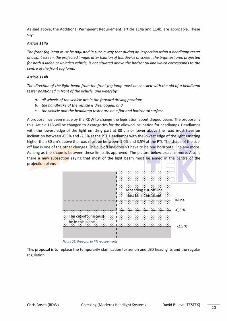
A proposal has been made by the RDW to change the legislation about dipped beam. The proposal is
this: Article 113 will be changed to 2 categories for the allowed inclination for headlamps. Headlamps
with the lowest edge of the light emitting part at 80 cm or lower above the road must have an
inclination between -0,5% and -2,5% at the PTI. Headlamps with the lowest edge of the light emitting
higher than 80 cm’s above the road must be between -1,0% and 3,5% at the PTI. The shape of the cut-
off line is one of the other changes. The cut-off line doesn’t have to be one horizontal line any more.
As long as the shape is between these limits its approved. The picture below explains more. Also is
there a new subsection saying that most of the light beam must be aimed in the centre of the
projection plane.
This proposal is to replace the temporarily clarification for xenon and LED headlights and the regular
regulation.
0-line
-0,5 %
-2.5 %
The cut-off line must
be in this plane
Ascending cut-off line
must be in this plane
Figure 25. Proposal to PTI requirements

Chris Bosch (RDW) Checking (Modern) Headlight Systems David Bulava (TESTEK) 21
2. Slovakia In Slovakia this is the guideline for the procedure of checking the adjustment of the headlamps:
Guideline for checking headlamp setting during PTI
Article 1
Subject
The ministry of Transport and Construction of the Slovak Republic pursuant to section 136(2) a of the
thirty-eighth point of Act no. 106/2018 on the operation of vehicles in the road traffic and on
amendments and supplements to certain acts, issues a methodological guideline laying down the
procedure for checking headlamp setting for control items:
a) 4.1.2 low beam - setting
b) 5.2 front fog light – setting
Article 2
Definition of basic terms
For the purposes of this guideline, the following definitions shall apply:
a) by a parameter defining the headlamp setting, the inclination of the beam of light emitted by
the headlamp
b) the inclination of the beam emitted by the headlamp (inclination) is a planar angle between
the headlamp beam and the horizontal longitudinal plane in the vertical longitudinal plane; the
unit at which the inclination is given is the percentage(%)
Article 3
General principles for checking headlamp setting
1) For the purpose of checking the headlamp setting… it´s used device called headlight tester
(calibrated every year)
2) 2)… and the associated planar flat surface (calibrated every 10years, flat surface with accuracy
of 2mm per 1m)
3) During checking the headlights, the vehicle must be loaded to the service mass, this means that
for the purpose of guideline, the vehicle must be occupied at the driver´s seat during checking
the headlight
4) The device must be aligned with the vehicle
5) If the vehicle is equipped with a manually adjustable levelling headlamp device according to
the load, the control of device must be set to the position corresponding to the current state of
load of the vehicle

Chris Bosch (RDW) Checking (Modern) Headlight Systems David Bulava (TESTEK) 22
Uniform conditions for the inclination of low beam headlights and front fog lights
Low beam lights
1. The inclination of the low beam light must not differ more than 1% downwards and more than 0,5%
upwards from the basic adjustment.
2. The nominal value of the basic inclination of the low beam light is determined by the vehicle
manufacturer. If there is no information available of the basic pitch setting of the low beam light, then
the default setting for the purpose of this control item shall be understood as:
a) on the vehicles other than those of category T and PS a downward inclination of 1% to 2%
b) on the vehicles of category T and PS, the range of inclination 0,5% to 4% downward, when the
headlamps are located between 500mm and 1200mm, or the range of inclination 0,5% to 6%
downward when the headlamps are located between 1200mm to 1500mm.
3. On the vehicles put into service from 1.10.1984, other than those of category T and PS, the value of
the basic low beam light inclination must be indicated near the headlamps, directly on one of the
headlamps or on the vehicle´s production plate.
Fog lights
In the case of the measurement of beam inclination of front fog lamps, it shall be treated in the same
way as for the low beam headlamps, but with the front fog lamps on.
As read above the legislation between the countries are similar but have some crucial differences.
For instance Slovakia has a tolerance field, between 0,5% and 1%, while the Netherlands has a
tolerance field from 0,5% to 4%.
Figure 26. Tolerance field in which the measured inclination of the headlamp beams must lie

Chris Bosch (RDW) Checking (Modern) Headlight Systems David Bulava (TESTEK) 23
3. ECE regulations Depending on the type of headlamp, a different ECE regulation is applied. To know what needs to be
changed in the PTI about modern headlamps first you need to know how it got type-approved and
what is approved for the road. Below here is a list of the ECE regulations that is relevant for this
report:
- ECE No 1: Headlamps emitting an asymmetrical dipped beam or driving beam or both and
equipped with R2/HS1 filament lamps
- ECE No 8: Headlamps emitting an asymmetrical dipped beam or driving beam or both and
equipped with halogen filament lamps (not H4)
- ECE No 20: Headlamps emitting an asymmetrical dipped beam or driving beam or both and
equipped with halogen H4 filament lamps
- ECE No 37: Filament lamps for use in approved lamp units or power-driven vehicles
- ECE No 48: Installation of lighting and light-signaling devices
- ECE No 98: Headlamps with gas-discharge light sources
- ECE No 99: Gas-discharge light sources
- ECE No 112: Headlamps emitting an asymmetrical dipped beam or driving beam or both and
equipped with filament lamps and/or light emitting diode modules
- ECE No 113: Headlamps emitting a symmetrical dipped beam or main beam or both and
equipped with filament, gas-discharge light sources or LED modules
- ECE No 123: Adaptive front-lighting systems (AFS)
- ECE No 128: Light emitting diode light sources
The links to these regulations is found in the sources. As well as the above ECE regulations that is
used for this study the guideline 2014/45/EU was also used. This guideline talks about the PTI.
Unfortunately this guideline doesn’t say anything about the adaptive headlamps.

Chris Bosch (RDW) Checking (Modern) Headlight Systems David Bulava (TESTEK) 24
9. Delineation The main focus of this research is on dipped beam lights. The reason why, is the fact that the improper
adjustment of the light can endanger both the driver as well as the other traffic participants. If the
inclination of light is too downward, the driver has limited distance visibility. On the other hand, if the
inclination is too upward, the driver has great visibility, but the drivers driving in opposite direction are
blinded by that light. The inclination could be caused not only by improper adjustment, it also can be
affected by the different pressure in the tires. That is the reason why we were focused on these two
topics:
a) What is the influence of a deviation in the floor compared to horizontal longitudinal axis and
horizontal width axis of the vehicle on the adjustments of the headlights?
b) What is the influence of the tire pressure on the dipped beam adjustment?
c) What is the influence of the position on the steering wheel?
Another focus was on main beam lights. This is because most manufacturers are now focussing on
main beam with their new systems, but the regulations are still focussing on dipped beam.
This research doesn’t have a focus on rear or brake lights, only on front lights. A part of the focus is on
the AFS systems found in headlights these days. The reason is that mostly the front lights keep causing
blinding situations and that is where most of the innovations are found.

Chris Bosch (RDW) Checking (Modern) Headlight Systems David Bulava (TESTEK) 25
10. Results In this chapter the sub questions are answered.
1. What factors have an influence on the adjustment of the headlight? Multiple factors have an influence on the adjustment of the headlight. In this research the
factors that were researched are floor space, deviation in the floor, tire pressure, position of
steering wheel, the position of the steering wheel.
1. What is the influence of a deviation in the floor compared to horizontal
longitudinal axis and horizontal width axis of the vehicle on the adjustments
of the headlights? This was tested in 2 places. At Explora in Netherlands and at Homola in Slovakia. At
Explora we wanted to test it with thin plates under the wheels which they didn’t have
unfortunately. That is why the vehicle lift was used. This test is used to simulate a
deviation in the floor and should show the importance of having an even floor when
testing the headlamp. With a tape measure next to the vehicle, the height of the wheel
well was measured through the center of the wheel. After the car was lifted 1 or 0,5 cm
in the front or the rear, the pitch angle of the car was noted from a digital headlight
tester (Maha MLT 3000). The height at which the test started was the standard height
the car is set to. The base height of the wheel well is 67 cm. The car was lifted on the
front or the rear axle.
Height of wheel well [cm]
Front / rear Pitch angle left headlight [%]
Pitch angle right headlight [%]
67 Rear -0,3 -1,1
68 Rear -0,8 -1,2
69 Rear -1,3 -1,6
70 Rear -1,6 -1,9
71 Rear -1,8 -2,1
67 Front -0,3 -1
67,5 Front -0,6 -1,0
68 Front -0,6 -0,9
69 Front -0,1 -0,5
70 Front 0.2 -0,1
71 Front 0,6 0,4
Table - Results vehicle lift
Figure 28. Wheel well Figure 28. Vehicle lift

Chris Bosch (RDW) Checking (Modern) Headlight Systems David Bulava (TESTEK) 26
At the time of the test was noticed that when the vehicle was lifted in the front 1 cm
there was a weird value. The same circumstances were repeated to get another result.
The result stayed the same.
Graph – VW Golf
Graph – VW Golf
As showed in the graphs above a deviation in the floor has an effect on the inclination
of the headlights. As the floor becomes more raised, for instance when the vehicle is
lifted in 1 cm in the air on the right-side, the inclination of the right headlamp grows
from -1,1 to -0,9. A grow of 18%. Which is quite an increase and this is just 1 cm. That
1 cm represents a deviation in floor of 1 cm divided by the wheel base of the test
vehicle. In this case the wheel base of the test vehicle was 262 cm. Which means a
deviation of 0,38 cm/m (or 3,8 mm/m). Most deviations that are allowed in floor in
Slovakia, Germany or Belgium are lower than that. The strictest standard for deviations
in the floor is in Slovakia and Germany which is 0,2 cm/m (or 2 mm/m).
If we do this for when the test vehicle is raised for 2 cm on the right side, the decrease
is even bigger. The inclination drops from -1.1% to -0.5%. which is an increase of 54%.
The deviation in floor doubles to 0,76 cm/m which is well above most standards.
66
67
68
69
70
71
72
-1,2 -1 -0,8 -0,6 -0,4 -0,2 0 0,2 0,4 0,6 0,8
Hei
ght
axle
[cm
]
Inclination [%]
Front axle
Left headlight Right headlight
66
67
68
69
70
71
72
-2,4 -2,2 -2 -1,8 -1,6 -1,4 -1,2 -1 -0,8 -0,6 -0,4 -0,2 0
Hei
ght
axle
[cm
]
Inclination [%]
Rear axle
Right headlight Left headlight

Chris Bosch (RDW) Checking (Modern) Headlight Systems David Bulava (TESTEK) 27
This can also be done for the left side but due to the weird value this wouldn’t give
such a good example.
This subject was tested again at Homola in Slovakia. This time thin plates of wood were
used to test. The plates of wood had a thickness of 6 mm. The test vehicle and location
were different than in Explora. The specifics of this test are found in the document
“Testing Results Homola” in the annex. The same headlight tester was used though.
Thickness under the …..wheels [mm]
Pitch angle of left headlight [%]
Pitch Angle of right headlight [%]
Front
0 -2.0 -2.2
6 -1.5 -1.5
12
-1.3 -1.4
18 -1.0 -1.1
24 -0.9 -0.8
30 -0.5 -0.7
Rear
0 -2.0 -2.2
6 -2.1 -2.1
12 -2.3 -2.5
18 -2.6 -2.7
24 -2.8 -3.0
30 -3.1 -3.2
Table – Result plates under the wheels
Figure 29. The wooden plates

Chris Bosch (RDW) Checking (Modern) Headlight Systems David Bulava (TESTEK) 28
Graph – VW Tiguan
The wheelbase of the test vehicle at Homola1 was 2,604 m. With 1 plate (a thickness
of 6 mm) the car supposedly stands on a floor with a deviation of 2,3 mm/m. This is
between the standards of Germany (2 mm/m) and Belgium (2,5 mm/m). The
inclination changes form -2,0% to -1,5% for left and from -2.2% to 1.5 % for right. Add
another plate and the deviation becomes well above all standards within the EU to 4,6
mm/m.
The inclination on the front axle test vehicle were between the allowed PTI regulations
standards of the Netherlands during the whole test. The test values never became
higher than 0,5%, which is the limit, in the test with the plates under the front wheels.
According to Slovakian regulations which says the standard value of the headlamp
which is set by the manufacturer must not differ more than 0,5% upwards. The
standard value which the manufacturer decides must be between -1% and -2%. If the
test value drops upwards of -0,5%, the vehicle will fail. In this test even with 30 mm
under the front wheels it does not exceed this value. Though if the headlamps would
be adjusted on a floor with this deviation, the adjustment would be wrong by a full
1,0%. This is a big margin. All the test value might stay between the borders of the
regulations but with an adaptive headlamp the adjustment shouldn’t be wrong at all.
In that case a difference of 1% could mean a blinding headlamp.
The wooden plates does have an effect on the pitch angle of the vehicle with them
underneath the front wheels. The higher the pitch angle, the higher the headlights are
pointed at the road. If a car was adjusted on a floor with this type deviation in the floor,
the headlights would be adjusted to high. The headlight would create a lot of glare for
other road users.
1 Homola is an equipment supplier of vehicle lifts and headlight testers in Bratislava, Slovakia that a has a connection to TESTEK.
-2,5
-2
-1,5
-1
-0,5
0
0 6 12 18 24 30
Pit
ch a
ngl
e [%
]
Thickness of wooden plates [mm]
Deviation in the floor - Front Axle
Left headlight Right headlight

Chris Bosch (RDW) Checking (Modern) Headlight Systems David Bulava (TESTEK) 29
Graph – VW Tiguan
The inclination on the rear axle test vehicle were between the allowed PTI regulations
standards of the Netherlands during the whole test. The test values never became
higher than 4%, which is the limit, in the test with the plates under the front wheels.
Currently that are the regulations but the RDW is working on a new proposal to
changes this values. The new lower limit would be -2,5% which the vehicle exceeded
after just 2 plates under the rear wheels.
According to Slovakian regulations which says the standard value of the headlamp
which is set by the manufacturer must not differ more than 1% downwards. The
standard value which the manufacturer decides must be between -1% and -2%. If the
test value drops downwards of -3%, the vehicle will fail. In this test only with 30 mm
under the rear wheels the inclination exceeded this value. As with the test on the front
axle, if the headlamps would be adjusted on a floor with this deviation, the adjustment
would be wrong than 1,0%. This is a big margin.
The wooden plates also have an effect on the pitch angle with the plates underneath
the rear wheels. The lower the pitch angle the more the headlights are adjusted
downwards and the less lit the road is. If a car was adjusted on a floor with this type
deviation in the floor, the headlights would be adjusted too low. The headlight
wouldn’t light enough of the road and could cause an accident.
2. What is the influence of the tire pressure on the dipped beam adjustment? Tire pressure affects wheel height. The lower the tire pressure is, the lower the height
of the wheel is. When the pressure is equal in all four wheels, there should not be any
influence on the dipped beam adjustment. The problem occurs, when the tire pressure
is lower on the pair of wheels on the same axle, or on the same side of the vehicle. The
difference of the pressure that causes change of the wheel height results in an
inclination of the vehicle according to longitudinal, or transverse axis of the vehicle.
-3,5
-3
-2,5
-2
-1,5
-1
-0,5
0
0 6 12 18 24
Pit
ch a
ngl
e [%
]
Thickness of wooden plates [mm]
Deviation in the floor - Rear axle
Left headlight Right headlight

Chris Bosch (RDW) Checking (Modern) Headlight Systems David Bulava (TESTEK) 30
Our test started with inflating the wheels to a nominal value. Then we gradually
decreased the value of tire pressure to 75%, 50% and 25% of the nominal value on the
pair of the wheels on rear axle, front axle, left side and right side of the vehicle.
Tire pressure [kPa] Difference of the pitch angle, left headlight Δ [%]
Difference of the pitch angle, right headlight Δ [%] Front
left Front right
Rear left
Rear right
220 220 220 220 0 0
220 220 160 160 0,2 0,1
220 220 110 110 0,4 0,3
220 220 60 60 0,9 0,9
160 160 220 220 -0,2 -0,2
110 110 220 220 -0,8 -0,8
60 60 220 220 -1,5 -1,4
Table – tire pressures and difference of the pitch angles according to change on the rear and front axle – VW Tiguan
Tire pressure [kPa] Difference of the pitch angle, left headlight Δ [%]
Difference of the pitch angle, right headlight Δ [%] Front
left Front right
Rear left
Rear right
240 240 240 240 0 0
240 240 180 180 0,3 0,3
240 240 120 120 0,5 0,5
240 240 60 60 0,7 0,7
180 180 240 240 0 0
120 120 240 240 -0,4 -0,4
60 60 240 240 -0,7 -0,7
Table – tire pressures and difference of the pitch angles according to change on the rear and front axle – VW Golf
Chris Bosch (RDW) Checking (Modern) Headlight Systems David Bulava (TESTEK) 31
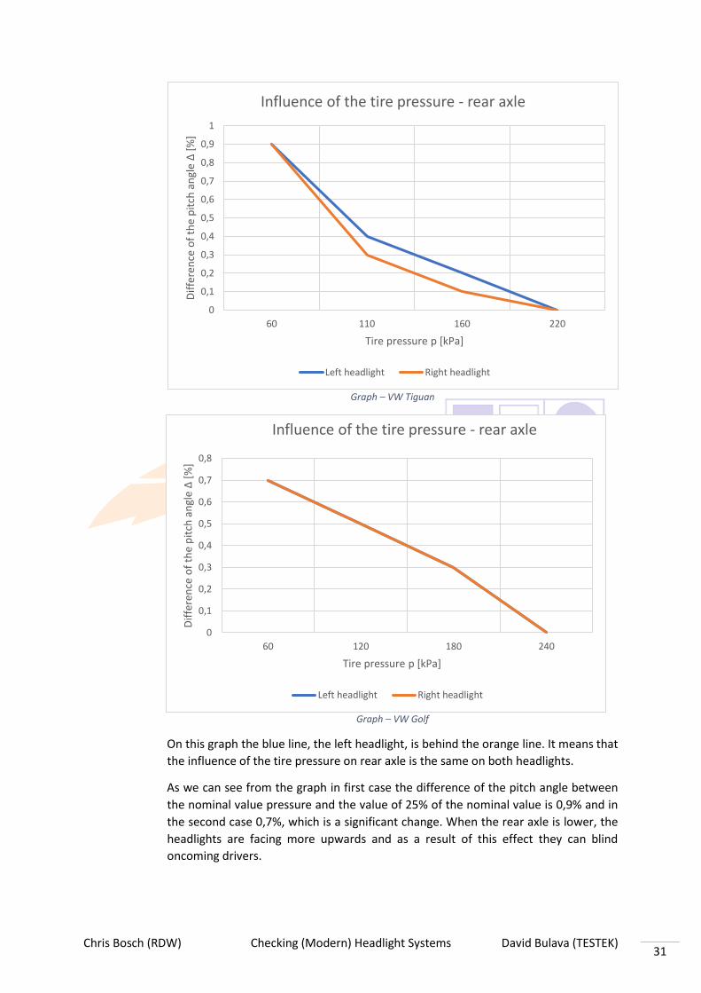
Graph – VW Tiguan
Graph – VW Golf
On this graph the blue line, the left headlight, is behind the orange line. It means that
the influence of the tire pressure on rear axle is the same on both headlights.
As we can see from the graph in first case the difference of the pitch angle between
the nominal value pressure and the value of 25% of the nominal value is 0,9% and in
the second case 0,7%, which is a significant change. When the rear axle is lower, the
headlights are facing more upwards and as a result of this effect they can blind
oncoming drivers.
0
0,1
0,2
0,3
0,4
0,5
0,6
0,7
0,8
0,9
1
60 110 160 220
Dif
fere
nce
of
the
pit
ch a
ngl
e Δ
[%]
Tire pressure p [kPa]
Influence of the tire pressure - rear axle
Left headlight Right headlight
0
0,1
0,2
0,3
0,4
0,5
0,6
0,7
0,8
60 120 180 240
Dif
fere
nce
of
the
pit
ch a
ngl
e Δ
[%]
Tire pressure p [kPa]
Influence of the tire pressure - rear axle
Left headlight Right headlight

Chris Bosch (RDW) Checking (Modern) Headlight Systems David Bulava (TESTEK) 32
Graph – VW Tigaun
Graph – VW Golf
On this graph the blue line, the left headlight, is behind the orange line. It means that
the influence of the tire pressure on front axle is same on both headlights.
In these two graphs we can see that the difference of the pitch angle at the value of
25% of the nominal value is recognizably different, in the first case it is -1,4% (-1,5%),
in the second case it is -0,7%. The difference can be caused by the higher weight of the
VW Tiguan or by some difference in the suspension. Due to the change of the tire
-1,6
-1,4
-1,2
-1
-0,8
-0,6
-0,4
-0,2
0
60 110 160 220
Dif
fere
nce
of
the
pit
ch a
ngl
e Δ
[%]
Tire pressure p [kPa]
Influence of the tire pressure - front axle
Left headlight Right headlight
-0,8
-0,7
-0,6
-0,5
-0,4
-0,3
-0,2
-0,1
0
0,1
60 120 180 240
Dif
fere
nce
of
the
pit
ch a
ngl
e Δ
[%]
Tire pressure p [kPa]
Influence of the tire pressure - front axle
Left headlight Right headlight

Chris Bosch (RDW) Checking (Modern) Headlight Systems David Bulava (TESTEK) 33
pressure at front axle the front axle lowers and the inclination of the vehicle is
changed. The inclination causes the headlights to point more downwards and do not
illuminate enough of the road ahead.
What both vehicles on either axles show is that a difference in tire pressure definitely
has an effect on the pitch angle of the headlights. This shows that when checking the
headlights the importance of having the correct tire pressure.
Tire pressure [kPa] Difference of the pitch angle, left headlight Δ [%]
Difference of the pitch angle, left headlight Δ [%] Front
left Rear left
Front right
Rear right
220 220 220 220 0 0
220 220 160 160 -0,1 0
220 220 110 110 -0,1 -0,1
220 220 60 60 -0,2 -0,1
160 160 220 220 0 -0,1
110 110 220 220 -0,1 -0,2
60 60 220 220 -0,3 -0,3
Table – tire pressures and difference of the pitch angles according to change on the left and right side – VW Tiguan
Tire pressure [kPa] Difference of the pitch angle, left headlight Δ [%]
Difference of the pitch angle, left headlight Δ [%] Front
left Rear left
Front right
Rear right
240 240 240 240 0 0
240 240 180 180 0,1 0,2
240 240 120 120 0,1 0,1
240 240 60 60 0,2 0,1
180 180 240 240 0 0,1
120 120 240 240 0 0
60 60 240 240 -0,1 0
Table – tire pressures and difference of the pitch angles according to change on the left and right side – VW Golf

Chris Bosch (RDW) Checking (Modern) Headlight Systems David Bulava (TESTEK) 34
Graph – VW Tiguan
Graph – VW Golf
The blue line doesn´t end on a value of 120kPa, it continues until 240kPa under the
orange lane, because the values are the same.
-0,5
-0,4
-0,3
-0,2
-0,1
0
0,1
0,2
60 110 160 220Dif
fere
nce
of
the
pit
ch a
ngl
e Δ
[%]
Tire pressure p [kPa]
Influence of the tire pressure - right side
Left headlight Right headlight
-0,3
-0,2
-0,1
0
0,1
0,2
60 120 180 240
Dif
fere
nce
of
the
pit
ch a
ngl
e Δ
[%]
Tire pressure p [kPa]
Influence of the tire pressure - right side
Left headlight Right headlight

Chris Bosch (RDW) Checking (Modern) Headlight Systems David Bulava (TESTEK) 35
Graph – VW Tiguan
Graph – VW Golf
The blue line doesn´t end on a value of 120kPa, it continues until 240kPa under the
orange lane, because the values are the same.
From these graphs we can say that there is no major influence when the tire pressure
is different on one side of the vehicle. The influence is negligible, maximum is 0,3% and
these values could be caused by equipment inaccuracy. During the measurement we
found out, that values measured by digital headlight tester are oscillating ± 0,1%.
To sum up, we can say, that tire pressure has significant influence on the change of the
pitch angle, but only if the one axle is inflated on different pressure. Different pressure
on one side of the vehicle has just a slight effect. Nonetheless should the tire pressure
always be on the correct value, not only for the PTI
-0,2
-0,1
0
0,1
0,2
0,3
0,4
60 120 180 240
Dif
fere
nce
of
the
pit
ch a
ngl
e Δ
[%]
Tire pressure p [kPa]
Influence of the tire pressure - left side
Left headlight Right headlight
-0,4
-0,3
-0,2
-0,1
0
0,1
0,2
60 110 160 220
Dif
fere
nce
of
the
pit
ch a
ngl
e Δ
[%]
Tire pressure p [kPa]
Influence of the tire pressure - left side
Left headlight Right headlight

Chris Bosch (RDW) Checking (Modern) Headlight Systems David Bulava (TESTEK) 36
3. What is the influence of the position of the steering wheel on the dipped
beam adjustment? As noted during testing at Explora2, the
influence of the steering wheel on the
inclination depends on the type of
vehicle. On the test vehicle we had, which
was a Volkswagen Golf with McPherson
front suspension, it didn’t have any
influence as you can see on the table. The
specifics of the test and the specifications
of the test vehicle can be found in the
document ‘testreport Explora EN’’ in the
annex. The pitch angle didn’t change when the steering wheel moved to different
angles. The reason the values left and right isn’t the same is because the headlight
weren’t adjusted to same value. This way if there was any difference between left and
right it is easier to notice. In the end the goal of this test was to see if there was any
difference. In most regulations it says the front wheels have to stand straight at the
PTI test for checking the headlights.
Steering wheel
angle
[degrees]
Pitch angle left headlight [%] Pitch angle right headlight [%]
0 -0,7 -1,1
90 -0,7 -1,1
180 -0,7 -1,1
270 -0,7 -1,1
360 -0,7 -1,1
540 -0,7 -1,1
Table - Steering wheel angle with pitch angles
2 Explora is a Dutch workshop equipment supplier of tire equipment, vehicle lifts and headlight testers in Ede, Netherlands.
Figure 31. Caster
Figure 30. Citroen 2CV

Chris Bosch (RDW) Checking (Modern) Headlight Systems David Bulava (TESTEK) 37
This has to do with caster. Caster is the angle of the front wheels in the longitudinal
axis. The test vehicle didn’t have any caster so the wheel is completely upright. With a
vehicle that does have negative or positive caster, for instance a Citroën CV as pictured,
when the steering wheel is turned it will have an effect on the inclination of the
headlight because one headlight is lower to the ground than the other. This wasn’t
tested because such a vehicle wasn’t avalaible and most modern vehicles have neutral
casters set ups.
Even though it shows here that with most cars, it will not have any effect that doesn’t
mean the PTI requirements should change on that. Just for those vehicles were it will
have an effect should the wheels always be straight when checking the headlamps.
4. What is the influence of the position of a vehicle lift in the lowest position, in
a lock, hanging in the cables? This was tested in the RDW station in Den Bosch
with a laser. The laser that was used was a Bosch
Quigo III. This laser has an accuracy of roughly
0,8 mm/m. At first 3 measure points were
decided:
1. 20 cm in front of the laser
2. 1 m in front of the laser
3. 4 m in front of the laser
Measure point 1 was chosen a base line, a zero
point. The point 2 to see the deviation in a short
distance. Point 3 was chosen because of the
wheelbase of most vehicles. Most vehicles have
a wheelbase of 2,5 m to 3 m. Because between
point 2 and point 3 most of the weight will be on
the vehicle lift. The measured value is the
distance from the calibrated laser to the ground.
So, if the measured value is higher it means that on that point the bridge is on a lower
point.
The vehicle lift that was used for this test was a Stertil Koni ST 4040 L vehicle lift at the
RDW station. This lift has a capacity of 4000 kg. With most vehicle lifts and as with this
the lowest position is the same as the lift being on the floor. The height of the lock that
was used is at 48 cm high.
Figure 32. Measuring the deviation on the bridge

Chris Bosch (RDW) Checking (Modern) Headlight Systems David Bulava (TESTEK) 38
Distance from laser [m] Measured value [cm] Deviation [cm]
Lowest position
0,2 10,2 0
1 10,4 0,2
4 10,8 0,6
In a lock 48 cm high
0,2 10,2 0
1 10,5 0,3
4 11,1 0,9
Hanging in the cables
0,2 10,2 0
1 10,4 0,2
4 10,6 0,4 Table – influence of position of vehicle lift
The measured values seen up here in the table is the height that was measured with a
carpenter’s square in front of the laser at the 3 specific measure points. This test was
without a vehicle on the lift.
Graph – Position of vehicle lift
What we see is that the different positions in the vehicle lift does make a difference.
For instance, when the lift is in the lowest position and in a lock the start and end
results are the same. Over a distance of 2 m there is a deviation when the lift is in a
lock. The biggest difference is when the lift is hanging in the cables. This value does
differ the most from the other two but has the least deviation in it.
Most of the time if a vehicle is checked on the lift it will be done either in the lowest
position (on the floor) or in a lock. The deviation between 1 m and 4 m is now 3 or 4
mm per 3 m. According to most regulations from the UK , Belgium or Germany about
floors this is allowed.
10,1
10,2
10,3
10,4
10,5
10,6
10,7
10,8
10,9
0 0,5 1 1,5 2 2,5 3 3,5 4 4,5
Mea
sure
d v
alu
e [c
m]
Distance [m]
Influence of the position of the vehicle lift
Lowest position In a lock Hanging in the cables

Chris Bosch (RDW) Checking (Modern) Headlight Systems David Bulava (TESTEK) 39
The deviation of the vehicle lift has an effect when adjusting the headlight. For instance
we can now see that the lift is on an angle and isn’t completely level. Whether this is
caused by the lift not being calibrated evenly or over time the lift’s steel planking got
bent slightly is not completely clear. There is some deviation but the advantage with a
vehicle lift in contrast to a normal floor is that it can be adjusted quite easily. When
the vehicle lift is in the lock or in the lowest position it can be individually adjusted so
that lift is completely level.
But then again the vehicle lift can be level but if the headlight tester isn’t in the same
horizontal plane as the vehicle is, there is still going to be a difference and a wrong
adjustment.
5. What is the effect of bending a vehicle lift by a vehicle that’s on it? The effect of the vehicle was test as well in Den Bosch on the same day. This was tested
by repeating the test of sub question 1.4 but now with a vehicle on it. The vehicle was
a Mazda 3. This vehicle has a dry weight of 1275 kg and a wheelbase of 272,5 cm. the
table below shows the same test as with sub question 1.4 but now with a vehicle on
the lift
Distance from laser [m] Measured value [cm] Deviation [cm]
Lowest position
0,2 10,2 0
1 10,6 0,4
4 10,8 0,6
In a lock 48 cm high
0,2 10,2 0
1 10,7 0,5
4 11,2 1
Hanging in the cables
0,2 10,3 0
1 10,8 0,5
4 11,2 0,9 Table – effect of bending of a vehicle lift
Graph – Bending vehicle lift
10,1
10,2
10,3
10,4
10,5
10,6
10,7
10,8
10,9
0 0,5 1 1,5 2 2,5 3 3,5 4 4,5
Mea
sure
d v
alu
e [c
m]
Distance from laser [m]
In the lowest position
Without vehicle With vehicle

Chris Bosch (RDW) Checking (Modern) Headlight Systems David Bulava (TESTEK) 40
At both end of the lift the vehicle has no effect when it is in the lowest position. This
can be because when the lift is in the lowest position it is basically on the floor at
both ends. In the middle when it is unsupported the vehicle on the lift definitely has
an effect. It results in a deviation at 1 m of 2 mm.
Graph – In a lock
With the lift in a lock the vehicle causes about the same amount of deviation as when
the lift is in the lowest position but instead of the deviation disappearing at the end of
the lift it only reduces slightly.
Graph – Hanging in the cables
10,1
10,2
10,3
10,4
10,5
10,6
10,7
10,8
10,9
11
11,1
11,2
11,3
0 0,5 1 1,5 2 2,5 3 3,5 4 4,5
Mea
sure
d v
lau
e [c
m]
Distance from laser [m]
In a lock
Without vehicle With vehicle
10,1
10,2
10,3
10,4
10,5
10,6
10,7
10,8
10,9
11
11,1
11,2
11,3
0 0,5 1 1,5 2 2,5 3 3,5 4 4,5
Mea
sure
d v
alu
e [c
m]
Distance [m]
Hanging in the cables
Without vehicle With vehicle

Chris Bosch (RDW) Checking (Modern) Headlight Systems David Bulava (TESTEK) 41
The deviation is the biggest in this situation. This is probably caused by the stretching
cables because of the weight of the vehicle.
The conclusion of this sub question is that while the vehicle does have an effect on the
evenness and the bending of the lift. It is only a small deviation that is easily
manageable except for when the lift is hanging in the cables. As said above, a
technician is unlikely to check the headlight with the lift hanging in the cables.
6. Does the ambient lighting of the test location influence the light image and
the horizontal cut-off line produced by the (adaptive) headlight? In most countries the headlamp test is in a workshop or PTI station. Most adaptive
features of adaptive headlights don’t function when the vehicle is stationary. Most
features with adaptive headlamps start working from 30 km/h. These headlights which
are in automatic setting return to the basic dipped beam when stationary and below
30 km/h.
Some brands like Mercedes have created a workshop setting for the headlights. In the
newest Mercedes S-class this is initiated by putting the bonnet up. The matrix LED
headlamps go into a setting where it creates the ‘’basic dipped beam’’.
After having tested multiple vehicle at RDW stations no conclusive effect of the
ambient lighting was found during the testing of the headlamps in a stationary
condition.
2. What is the influence of damage (scratches, breaks or discoloration) of
the windshield on sensors or cameras? Most of the adaptive light systems work with a camera behind the windshield. This camera
isn’t just used by the headlamp systems but also by most ADAS systems like adaptive cruise
control, lane departure warning etc. Most of the contacted manufacturers said that when a
scratch or a break in the windshield in front of the camera if it obstructs it’s view the system
will malfunction and give an malfunction indicator lamp on the dashboard. Most
manufacturers disclaim in their vehicle manual at what conditions the system might
malfunction. When the system malfunctions the headlamps will return to the basic dipped
beam.
Another student will look into this subject in a next internship at the RDW.
3. Is it possible to check modern lights (eg. LED and Adaptive) pursuant
Directive 2014/45 /EU with analog test equipment? Yes, it´s possible because this directive doesn’t specifically talk about LED or adaptive lighting.
The directive says:” Determine the horizontal aim of each headlamp on dipped beam using a
headlamp aiming device or using the electronic vehicle interface.” There is nothing mentioned
about using analog or digital device. But due to experiences, the cut-off line of LED and
adaptive lights is no more the straight line and this fact could cause problems in the PTI´s. To
check lights with modern technologies it should be able to switch lights to the “test” mode. In
the test mode, the lights could be tested in a conventional way using both digital test
equipment and analog test equipment. The adjustment can be done with analog test
equipment but to get a more accurate and better adjustment it is recommended that a digital
headlight tester is used.

Chris Bosch (RDW) Checking (Modern) Headlight Systems David Bulava (TESTEK) 42
1. Is the result of a test on an analog test equipment reproducible on a digital
test equipment? When the test at Explora was conducted, an analog headlight tester was compared to
a digital one. Both were applicable in the test but the test was conducted with the
digital one. The analog tester was a Werther PH 20666/D/L1. The digital headlight
tester was a MAHA MLT 3000 what we found was that the digital tester gave more
accurate value’s than the analog tester. On the analog tester the value needed to be
read from a table on the light screen and on the digital tester it produced a value on
the digital screen. When the value has to be read from the analog tester there is a
small margin which isn’t easily to see with the human eye that a computer can see very
clearly.
One of the problems that we saw with the digital headlight tester was that it didn’t
stay on a specific value. It would have with a difference of 0,1 % between value’s. What
we did to solve this was take a picture at that moment (which was an option on the
Maha) an use the value from the that for the results.
Up here are some photos showing the difference between a Hella-Gutmann analog
tester and a Hella-Gutmann digital tester on a modern LED headlamp. The modern
Figure 34. Seg IV
Figure 33. Seg V

Chris Bosch (RDW) Checking (Modern) Headlight Systems David Bulava (TESTEK) 43
headlamp here is from a 206 Renault Megane. The analog headlamp tester is the Hella-
Gutmann SEG IV. The digital headlamp tester is the Hella-Gutmann SEG V.
The benefit of using a digital headlamp
tester is the shape of the cut-off line can
be seen much clearer. As the pictures
above show.
A big difference between the Maha MLT
3000 is that while both devices show
arrows indication which way the light
beam needs to be corrected, the Maha
also shows an actual value of the pitch
angle on the screen immediately.
The downside of a digital tester is the price. For countries like the Netherlands where
there are 15000 PTI stations, this makes it harder to force the PTI stations the use of a
digital tester. Also does the tester still have to be in the same plane as the test vehicle.
4. Should we (in the future) check the operation of adaptive lighting in the
PTI? The short answer to this question is definitely. Studies have shown that when people have
ADAS systems they rely on them too much. For instance with blind spot monitoring at a certain
point when they have got used to the system they stopped looking over their shoulder. At
some point the system might fail because of an earlier crash or a wrong calibration of the
sensor. That situation could result in a crash. If the govern companies such as RDW or TESTEK
would have checked it during a PTI or some other inspection, it would have shown and the
possible crash would be prevented.
The same goes for ADAS systems that are relevant for this study. Such as adaptive high beam.
The vehicle should dim one of the matrix LEDs locally to ensure that oncoming traffic or traffic
ahead isn’t blinded. If the camera behind the windscreen isn’t calibrated right or the camera
does notice the vehicle but not on the right place, it will blind the driver. With modern LEDs
being so enormously bright,
the driver will not be able to
see for a couple of seconds.
So he or she won’t notice
when his vehicle will go off
the road and he could crash.
Off course this is an over
exaggeration but it shows a
worst case scenario.
Figure 36. Adaptive High Beam
Figure 35. Screen of Maha MLT 3000

Chris Bosch (RDW) Checking (Modern) Headlight Systems David Bulava (TESTEK) 44
1. Are adaptive lights easy to check during the PTI? Adaptive lights are complicated mechanisms and they require a lot of attention.
Application of the modern LED systems brings problems to PTI stations. TESTEK, as well
as RDW got a plenty of calls from technicians because they are used to the Halogen
and Xenon light systems and they don`t know how to evaluate the test of the modern
LED light systems, because they behave in a different way, they have different cut-off
line, which is not described in the methodology. The RDW solved this temporarily by a
clarification in the Dutch PTI regulations. This means a technician sometimes doesn’t
know how to check these lamps. The conclusion is that the actual light image (cut-off
line) can be checked but whether the adaptive functions actually work is not possible
to check during a PTI because these features don’t work when the vehicle is stationary.
Some manufacturers do allow you to check some functions of the adaptive headlamp
when connected to OBD but this is limited.
2. Is connecting to the OBD necessary, for example, with adaptive dipped beam? It depends on the manufacturer. You can check every lights without the connection to
the OBD, but nowadays, there are many possible modes of the lights and technicians
don`t know how to check them. Some producers decided, that their lights have to be
checked in the test mode, which is only accessible through the OBD. So the trend is,
that every checking and adjustment is going to be done using connection to OBD. In
the end we could say that OBD connection is becoming necessary during the
headlamps checking.
According to ECE regulation no 123 every adaptive headlamp has to have a neutral
setting which is the setting in which the dipped beam and main beam should be
checked. It depends on manufacturer how to engage this neutral setting. Some brands
as VW and Mercedes have to connect with an OBD reader to engage this setting.
3. What are the most common actions for checking adaptive light? The procedure should be almost the same as with the common lights. The car have to
be on the flat area, the tires should be inflated to the nominal value, the headlights
tester have to be aligned to a car. Then, the headlamps mode have to be switched from
the automatic to the basic dipped beam setting. As it`s mentioned in point 2, some of
the manufacturers demands to check their lights through the test mode, which is only
accessible through OBD connection. Then, one of the steps will be to set the test mode
in the OBD device. After all of that, you can check the headlamps.
4. In the future, will we need information from importers / manufacturers for
checking the dipped beam? For checking not specifically but for adjusting the headlamps definitely yes. If the trend
will continue and every brand will demand the connection through OBD, to get the test
mode, the technicians will need the information about where to find the connector,
because they would lose much time searching for connector on the different types of
cars. Also will they need information on which OBD system from which manufacturer
needs to be used and how this works. As well new cars have different basic settings of
dipped beam. The cut-off line is becoming a piece of history, it`s no longer a criterion
according to which the test of the modern systems is evaluated. We will need the
information from the manufacturer, how the basic dipped beam setting and the main
beam should look like.

Chris Bosch (RDW) Checking (Modern) Headlight Systems David Bulava (TESTEK) 45
Some manufacturers also have made a test mode for instance with the matrix LED
lamps of a Volkswagen Passat. To correctly adjust the headlamps a test mode must be
initiated using an OBD connector and specific steps have to be followed to do it
correctly. Also does Volkswagen recommend that main beam is adjusted after the
dipped beam.
5. Should the dipped beam be checked in the basic setting? This already happens. During the checking, all adaptive or automatic settings needs to
be switched off and turned to basic settings. As we said a few times earlier, some
brands already have a test mode, which is used for checking and adjusting dipped
beam. It is expected, that more and more brands will follow this, and there will be a
test mode in every car. In this case, the best solution for the PTI will be that the test
mode could be activated from the dashboard and the technicians won`t lose time
connecting the OBD and doing the settings. The problem is that ECE regulation demand
a neutral setting but don’t describe how and where.
5. When does the automatic dipped beam control of a vehicle start to work,
e.g. only driving, stationary. Should we also take into account during a
check that the dim lamps must first be rested after a ride? Automatic low beam control consists of automatic height adjustment and the actually
turning the headlamps on if the conditions are demand this. The sign of the initiation
of the system is a self-calibration of the headlamps that most adaptive headlamps do.
The self-calibration is usually down by swivelling from left to right and up to down to
reset the adjustment to zero and check if all the actuators of the systems are actually
working. When this actually happens is very brand specific. For instance, on a VW
Tiguan of 2016, the process happens when you engage drive on the transmission. It is
the same on a Mazda 3. On most BMW it happens when the engine is started.
For the car to complete and reset the headlight the engine should be turned off
completely and start again to initiate the self-calibration. Then the car is in its optimal
test environment.
1. Which modern lights are currently in use and which can we expect (in the
short term)? Due to not a lot of response from the contacted manufacturers this is a difficult
question to answer. Manufacturers didn’t answer all the question asked over the
email. Therefore, the only source for this inventory is the manufactures Dutch
websites. In this inventory the filament halogen headlights with or without LED DRL
were left out because almost every manufacturer has them. The headlamps searched
for are Xenon (HID), LED, Matrix LED and laser headlights as dipped or main beam
which are standard or available as an option.
A small part of the inventory is placed below. The full inventory will be added in the
annex as an attachment.

Chris Bosch (RDW) Checking (Modern) Headlight Systems David Bulava (TESTEK) 46
Brand System Name Type Headlamp AFS?
Alfa Romeo Bi-xenon headlights Xenon Yes
Alpine LED front headlights LED No
Audi Full-LED headlights LED Yes
Audi Matrix LED headlights Matrix LED Yes
Audi HD Matrix LED headlights Matrix LED Yes
Audi HD Matrix LED headlights with Audi Laserlight Laser Yes
Bentley ALL-LED headlamps LED Yes
Bentley LED Matrix headlamps Matrix LED Yes
Bentley Full LED adaptive headlamps with High Beam Assist LED Yes
BMW LED headlights with beam-throw control LED Yes
BMW Adaptive LED headlights Matrix LED Yes
BMW Adaptive LED headlights with BMW Laserlight Laser Yes
Citroen Full LED-headlights LED No
Citroen Xenon headlights Xenon No
DS DS Matrix LED Vision Matrix LED Yes
DS DS Active LED Vision LED Yes
Fiat Full LED headlights with Adaptive High Beam LED Yes
Fiat Full LED headlights LED Yes
Fiat Xenon headlights Xenon No
Ford Full LED headlights LED No
Ford Adaptive Lighting System with dynamic LED lamps LED Yes
Honda LED headlights LED No
Hyundai Full LED headlights LED Yes
Infiniti LED LED No
Jeep Bi-Xenon HID headlights Xenon No
Jeep Adaptive Bi-Xenon HID headlights Xenon Yes
Jeep Signature LED Lighting with DRL, dipped & main beam LED No
20
58
0
10
20
30
40
50
60
70
No Yes
Number of AFS headlamps
3
48
19
8
0
10
20
30
40
50
60
Laser LED Matrix LED Xenon
Number of Type Headlamps

Chris Bosch (RDW) Checking (Modern) Headlight Systems David Bulava (TESTEK) 47
Kia Full LED headlights with AFLS LED Yes
Kia Full LED headlights LED No
Land Rover LED headlights LED No
Land Rover Premium LED headlights with Signature DRL LED Yes
Land Rover Matrix LED headlights with signature DRL Matrix LED Yes
Land Rover Pixel LED headlights with AFS Matrix LED Yes
Land Rover Matrix-Laser LED headlights signature DRL Laser Yes
Lexus Bi-LED headlamps LED No
Lexus Triple LED headlamps with Multi weather function Matrix LED Yes
Lexus Triple LED headlamps with BladeScan Matrix LED Yes
Lexus Quad LED headlamps LED Yes
Maserati Adaptive BI-Xenon Headlamps Xenon Yes
Maserati LED Adaptive Matrix headlamp with Matrix LED Yes
Mazda Adaptive LED headlights Matrix LED Yes
Mazda LED headlights LED Yes
Mercedes-Benz High Performance LED lights LED Yes
Mercedes-Benz Multibeam LED Matrix LED Yes
Mini LED headlights LED Yes
Mini Adaptive Matrix LED headlamps Matrix LED Yes
Mitsubishi Bi-xenon Headlamps with LED citylight Xenon no
Mitsubishi LED-headlamps LED no
Nissan Intelligent Auto Headlamps with Full LED LED Yes
Nissan LED headlights LED no
Opel ECO LED headlamps LED Yes
Opel Full LED headlamps LED Yes
Opel IntelliLux Matrix headlamps Matrix LED Yes
Peugeot Xenon headlamps Xenon No
Peugeot Headlights with Peugeot Full LED technology LED Yes
Polestar Pixel LED headlamps Matrix LED Yes
Porsche Porsche Dynamic Light System LED Yes
Porsche Porsche Dynamic Light System Plus Matrix LED Yes
Renault LED Pure Vision headlamps LED Yes
Seat Full LED headlamps LED Yes
Skoda Full LED matrix headlamps Matrix LED Yes
Skoda Base LED headlamps LED No
Skoda Full LED headlamps with dynamic indicator, fog lamps and bend light LED Yes
Skoda LED headlamps with halogen indicators LED No
Smart Full LED headlamps LED Yes
Subaru LED headlamps LED Yes
Suzuki LED headlamps LED No
Suzuki LED headlamps LED Yes
Suzuki LED headlamps (dipped beam) LED No
Tesla LED headlamps LED Yes
Tesla Adaptive LED headlamps LED Yes

Chris Bosch (RDW) Checking (Modern) Headlight Systems David Bulava (TESTEK) 48
Toyota LED headlamps LED Yes
Toyota Bi-LED headlamps LED Yes
Toyota Matrix LED headlamps Matrix LED Yes
Volkswagen LED headlamps LED Yes
Volkswagen LED plus headlamps LED Yes
Volkswagen IQ Light LED Matrix headlamps Matrix LED Yes
Volvo LED headlights LED Yes

Chris Bosch (RDW) Checking (Modern) Headlight Systems David Bulava (TESTEK) 49
11. Discussion Even though the tests were performed with a lot of caution to get the right results, sometimes things
go wrong. At Explora we hoped to get an accurate test to simulate a deviation in the floor.
Unfortunately due to what was available we could only use the vehicle lift. Luckily at Homola, we had
thin plates of 6 mm to test with which gave a more precise result.
Another problem at Explora was the Tesla Model S which we wanted to use as a test vehicle but both
headlamps had an unusual cut-off line. Due to the time the decision was made to use another vehicle.
What this unusual cut-off line caused is still unknown. A possible explanation is a broken headlamp, a
wrong position of the headlamp or a software problem. A couple of weeks later we visited the same
Tesla again to try and analyse the problem. At that time the problem of the cut-off line had
disappeared. One of the possible solutions was a ‘’through the air update’’. When we entered the
vehicle, the dashboard said that a new update was recently installed.
One of the problems we saw the digital tester that while it was very precise, the value it exported to
the screen was constantly hovering with a difference of 0,1%. What we did to solve this is take a
snapshot on the machine which gave one still value we could use.
Also, one of the problems with as with all the analog tester the human eye can only see certain things
up to a certain degree very clear. Most H7 halogen lamps have a clear border where the cut-off line is
but with LED or xenon headlamps there is usually a small blue glow around the cut-off line which makes
it harder to see where the actual cut-off line is. Which can give problems when checking with an analog
headlight tester.
Figure 37. Cut-off line of Tesla at Explora
Figure 38. Blue glow with LED headlamps

Chris Bosch (RDW) Checking (Modern) Headlight Systems David Bulava (TESTEK) 50
12. Conclusion The main question of this report is:
How does the current PTI requirements concerning headlight systems have to be
revised and what can be improved?
Since this is an international report of a co-operation between the RDW and TESTEK there is no
definitive answer to that because both countries of the RDW and TESTEK have different PTI
requirements. One thing is for sure. The PTI requirements must change to accommodate new
innovations in the headlamp industry and keep it up to date. In what way it should change and in
certain aspect is described here and in the recommendations.
Usually checking the headlight is a less than 5 min job but with most new headlamps this is no longer
the case anymore. Firstly with most vehicles a test mode must be initiated to check the headlamp. One
of the definite thing that we noticed during this study was that every modern headlight this is different
and this means that checking the headlight isn’t a 5 min job anymore. If the headlights need to be
adjusted after this as well it will take even longer. To adjust the headlight there still are a couple of
screws but there are certain steps to be taken before adjusting the headlights. These steps depend on
what the manufacturer prescribes. This isn’t something specific for the PTI but in most cases it is
relevant because if the adjustment is wrong, the vehicle will fail the PTI and has to be adjusted. After
that it will come back to the PTI for rechecking.
This means that information from the manufacturer is needed to correctly adjust and check a
headlight. Information such as where is the actual centre of the light beam on the headlamp thus the
correct position of the headlamp tester in front of the headlamp. With modern LED headlamps
sometimes it isn’t clear which LED is producing which light. The precise position of the tester is very
important because a small disposition of the tester gives a wrong light image.
This information must be available to all workshops, not only brand specific workshops and PTI
stations. Most manufacturers of adaptive headlamps describe adjusting the main beam instead of the
dipped beam. What further information is necessary is specified in the recommendations. Due to this
complexity and need for manufacturers knowledge it raises the question whether the headlight testing
can still be done by a universal (non OEM) workshop in a every city or village. What can happen is that
a universal workshop without the right knowledge will only adjust the dipped beam which can result
in a wrong adjustment for the main beam. The vehicle would than pass the current PTI but could cause
glare for other road users. This while a OEM dealer knows how to check and adjust the headlamps
correctly. This is why the PTI requirements should add the checking of the adjustment of the main
beam as well. The main beam needs to be checked as well according to the manufacturers standards.
This means not only checking for vertical adjustment but also horizontal adjustment and setting the
adjustment to the manufacturers set standards. The reason we should check both in the PTI is that
also older cars have to go to the PTI. The focus with older cars will still be on dipped beam because
these still have older halogen lamps which doesn’t have the adaptive features.
The adaptive lamps can also be described as an ADAS system because these lamps use most of the
same sensors such as the camera in the windshield and/or navigation, speed and steering sensors. This
means that those sensors should also be checked in the PTI for the correct working. Drivers depend on
these systems while driving and doesn’t immediately notice the wrong adjustment or possible
malfunctions of these systems. This proves the point of that the ADAS should be checked periodically
like the headlamps. Most adaptive headlamps will return to basic dipped beam when it malfunctions
and show an error on the dashboard but in some cases it might not do so. Al lot about the behaviour

Chris Bosch (RDW) Checking (Modern) Headlight Systems David Bulava (TESTEK) 51
of ADAS is not known yet. Also when the vehicle is more than 10 years old and or not owned by the
first owner anymore the working of the ADAS is not known yet. Will the systems still function the same
way it did when the vehicle left the factory? This is why these need to be checked periodically at some
sort of PTI or in the current PTI.
The result of tests at Explora and Homola show that a deviation in floor and tire pressure have a
definite effect. That is why at the PTI the floor should be level to a certain standard and the tire
pressure should be on what the manufacturer prescribes.
13. Recommendations These are the recommendations of this study.
The PTI regulations as said in the conclusion should be more focused towards main beam. We
recommend in the future in the PTI both the dipped beam and main beam should be checked. This is
because also older vehicles still have to go to the PTI. As well as checking the headlamps, the whole
adaptive headlamp system should be checked such as the computer and the sensors. This can be done
by creating a separate PTI for ADAS or checking the ADAS in the current PTI procedure which is our
recommendation. Due to the importance of this adjustment of the sensor of ADAS, we recommend
that this is checked periodically as with the normal adjustment of the headlamps. The checking of the
AFS or ADAS features is hard to do while the vehicle is in a PTI station because most AFS or ADAS
features don’t work when the vehicle is stationary. We suggest using OBD diagnostics to check whether
the sensor and computers of the ADAS is working correctly in the PTI.
Another aspect with the ADAS that is important is the condition of the windshield in front of the
camera which should be intact. In the Dutch PTI the part of the windshield in front of the driver, the
direct field of vision, is checked. This should be expanded to checking the area in front of the camera
to the same standards as well.
The information that each manufacturer should be made available for every PTI station or workshop
is the following:
- The correct inclination;
- The centerpoint of the dipped / main beam on the headlamp;
- Whether adjusting main beam or dipped beam or both and in which order;
- Initiation the test mode (neutral setting of the headlamp) and the whole testing and
adjusting procedure;
- What brand of OBD device and brand of headlamp tester should be used;
- What AFS features the test vehicle has.
This information should be easily accessible for all PTI technicians. The best solution that there is a
universal or standardized OBD device that can be used with each headlamp from all brands for
correct checking and adjusting. Also should these systems contain a guide of how the test procedure
works with every vehicle. This will not create any problems between workshop having different
devices and not being able to check and adjust all vehicles.
We also recommend moving from an analog tester to a digital tester. This because with new vehicles
this is necessary, especially with the future in mind. With modern lights the cut-off line is more
difficult to see with the human eye on an analog tester. A digital tester solves this by using a camera.
This camera is also much more precise. Digital tester are more fool proof as well. They show 4 arrows
which way the light has to be adjusted and a check mark when the adjustment is right. Also with the
PTI also older vehicles have to be checked and with a digital tester you can still check halogen lamps.
Chris Bosch (RDW) Checking (Modern) Headlight Systems David Bulava (TESTEK) 52
As for the OBD device, the same should apply for a headlight tester. A standardized or universal
device for all brands is the best. We realise that this is something that might have to be handled at
UN/ECE level and that is not possible for local governments such as the RDW and TESTEK but both
the RDW and TESTEK can recommend this in the European Economic commission. Another
advantage of the digital tester is that this can communicate with the OBD device.
Another option instead of a universal / standardized headlamp tester and OBD device is that the
manufacturer should clearly detail which OBD device and headlamp tester should be used with their
vehicles. Only the workshops or PTI station with that equipment are allowed to do the PTI for that
manufacturers vehicles. This is an option but we do not advise it because it creates differences
between the PTI station and/or workshops. To prevent fraud in the PTI extra checks are needed than.
Not only the actual device and vehicle should have certain requirements but also the floors and the
place of the headlamp tester need requirements. In most countries in Europe are already
requirements for headlamp testers and where headlamps should be adjusted. The results of the tests
at Explora and Homola show that a deviation in the floor and in tire pressure definitely has an effect
on the adjustment of the headlights. This means that a level floor for the headlight tester and the
test vehicle is up most important. Also is maintaining the correct tire pressure. Due to a worsened
MPG and extra tire wear when not using the correct tire pressure this is something every driver
should not only do for the PTI but always.
14. Reverences Not only digital sources where used in this study. The list below shows the people that helped by
gathering information and discussing certain subjects.
- RDW employees
- TESTEK employees
- The experts of Explora who helped us
- The experts of Homola who helped us
- The experts of Hella who helped us
- Piet Schäfer
- Arthur van Lee
- Juraj Matej
- The contacted manufacturers or importers who supplied information
o BMW
o Ford
o Kia
o Mazda
o Mercedes-Benz
o PON (Dutch importers of VAG)
o Nissan
o Toyota
o Volvo

Chris Bosch (RDW) Checking (Modern) Headlight Systems David Bulava (TESTEK) 53
15. Glossary
Terminology Meaning Terminology Meaning
RDW Dienst Wegverkeer Headlight The beam the headlamp creates and shines out
TESTEK Technická Sluzba Technickej Kontroly
Dipped beam Low beam / passing beam
PTI Periodic Technical Inspection High beam Main beam / driving beam
AFS Adaptive Front lighting Systems Headlamp tester
Beamsetter
LED Light Emitting Diode ADAS Advanced Driver Assistance systems
DRL Daytime Running Lights Headlamp The actual complete assembly of the lighting system
Pitch angle Inclination
Sources Front page
1. Image on front page
Lumiled Aken (n/a). Retrieved November 13, 2019 got from Piet Schäfer, RDW.
Introduction
1. Figure 1&2
Koenen, A. (n/a). De geschiedenis van de automobiel verlichting. Retrieved December 16,
2019 from https://www.louwmanmuseum.nl/nieuws/nieuws-overzicht/automobiel-
verlichting.aspx
2. Koenen, A. (n/a). De geschiedenis van de automobiel verlichting. Retrieved December 16,
2019 from https://www.louwmanmuseum.nl/nieuws/nieuws-overzicht/automobiel-
verlichting.aspx
3. Figure 3
Cassey, D (2015). From Lamps to Lasers: The evolution of Headlights. Retrieved December
16, 2019 from https://www.carthrottle.com/post/from-lamps-to-lasers-the-evolution-of-
headlights
4. Cassey, D (2015). From Lamps to Lasers: The evolution of Headlights. Retrieved December
16, 2019 from https://www.carthrottle.com/post/from-lamps-to-lasers-the-evolution-of-
headlights ddf
5. von Berg, M (n/a). Audi TT 8S Matrix-LED-Scheinwerfer Abblendlicht LED-Tagfahrlicht.
Retrieved December 16, 2019 from https://www.carthrottle.com/post/from-lamps-to-lasers-
the-evolution-of-headlights
Management Summary
6. Figure 4
Lighttimes Online (24-6-2015). LRC Evaluating Audi Adaptive High Beam Headlights.
Retrieved January 27, 2020 from http://www.solidstatelighting.net/lrc-evaluating-audi-
adaptive-high-beam-headlights/

Chris Bosch (RDW) Checking (Modern) Headlight Systems David Bulava (TESTEK) 54
Theme
7. ANWB (26-11-19). Verblinding door autoverlichting. Retrieved November 27, 2019 from
https://www.anwb.nl/binaries/content/assets/anwb/pdf/auto/nieuws-en-tips/verblinding-
door-autoverlichting-2019.pdf
8. Ensie (22-12-2016). Definitie verblinden. Retrieved December 16, 2019 from
https://www.ensie.nl/muiswerk/verblinden
Theoretical Framework
9. Figure 5&6
Koenen, A. (n/a). De geschiedenis van de automobiel verlichting. Retrieved December 16,
2019 from https://www.louwmanmuseum.nl/nieuws/nieuws-overzicht/automobiel-
verlichting.aspx
10. Figure 7&9
Hella (n/a). Headlights. Retrieve January 9, 2020 from
https://www.hella.com/techworld/uk/Technical/Automotive-lighting/Headlights-219/
11. Figure 8
Allen, M (19-5-2011). How Your Headlights Work. Retrieved January 1, 2020 from
https://www.popularmechanics.com/cars/how-to/a6672/how-your-headlights-work/
12. Figure 10
Laukkonen, J.(3-12-2019). What are projector headlights. Retrieved January 21, 2020 from
https://www.lifewire.com/what-are-projector-headlights-4582305
13. Figure 11
Hella(n/a). Xenon headlights. Retrieved 18-1-2020 from
https://www.hella.com/techworld/uk/Technical/Automotive-lighting/Xenon-headlights-218/
14. Figure 12
Image of difference between Halogen and HID Xenon lights. Retrieved January 19, 2020 from
https://www.hidextra.com/blog/the-difference-between-halogen-hid-and-led-bulbs/
15. Figure 13 & 14
Hella (n/a). LED Headlights. Retrieved January 16, 2020 from
https://www.hella.com/techworld/uk/Technical/Automotive-lighting/LED-headlights-833/#
16. Figure 15
Caricos (11-4-2018). 2019 Ford Focus Hatchback, Wagon, and Active (Euro-spec) Image #37.
Retrieved on January 27, 2020 from
https://www.caricos.com/cars/f/ford/2019_ford_focus_eu/images/37.html
17. Figure 16 & 18
Mercedes-Benz. (n/a). MULTIBEAM LED headlamps in the new E-class. Retrieved January 21,
2020 from https://www.mercedes-benz.com/en/innovation/multibeam-led-headlamps-in-
the-new-e-class-video/
18. Figure 17
Hella (n/a). LED Headlights. Retrieved January 16, 2020 from
https://www.hella.com/techworld/uk/Technical/Automotive-lighting/LED-headlights-833/#
19. Figure 19
Kumar, R. (25-7-2014). Retrieved January 19, 2020 from https://www.quora.com/How-do-
BMWs-new-laser-headlights-work-and-what-advantage-do-they-have-over-other-headlight-
technologies

Chris Bosch (RDW) Checking (Modern) Headlight Systems David Bulava (TESTEK) 55
20. Figure 20 & 22
Mercedes-Benz (n/a). Let there be light: the LED headlamps of the new E-Class. Retrieved
January 22, 2020 from https://www.mercedes-benz.com/en/innovation/vehicle-
development/let-there-be-light-the-led-headlamps-of-the-future-e-class/
21. Hella (n/a). Bend Lighting. Retrieved January 22, 2020 from
https://www.hella.com/techworld/uk/Technical/Automotive-lighting/Bend-lighting-703/
22. Figure 23
Maha (n/a). User manual Maha MLT 3000. Retrieved January 28, 2020 from
https://www.maha.de/cps/rde/xbcr/SID-3FD7492A-98D6DC1D/maha_de/BA380701-en.pdf
23. Figure 24
Maha (n/a). Image of digital headlight tester. Retrieved January 20, 2020 from
https://www.maha.co.nz/digital-headlight-tester-mlt3000/
24. Koenen, A. (n/a). De geschiedenis van de automobiel verlichting. Retrieved December 16,
2019 from https://www.louwmanmuseum.nl/nieuws/nieuws-overzicht/automobiel-
verlichting.aspx
25. Cassey, D (2015). From Lamps to Lasers: The evolution of Headlights. Retrieved
December 16, 2019 from https://www.carthrottle.com/post/from-lamps-to-lasers-the-
evolution-of-headlights
26. Allen, M (19-5-2011). How Your Headlights Work. Retrieved January 1, 2020 from
https://www.popularmechanics.com/cars/how-to/a6672/how-your-headlights-work/
27. Woodford, C (14-10-2018). Incandescent Lamps. Retrieved January 1, 2020 from
https://www.explainthatstuff.com/incandescentlamp.html
28. Hella (n/a). Basic principles of car lighting technology. Retrieved January 9, 2020 from
https://www.hella.com/techworld/uk/Technical/Automotive-lighting/Basic-principles-of-car-
lighting-technology-220/
29. Hella (n/a). LED Headlights. Retrieved January 16, 2020 from
https://www.hella.com/techworld/uk/Technical/Automotive-lighting/LED-headlights-833/#
30. Lacoma, T (n/a). Halogen vs Xenon. Retrieved 19-1-2020 from
https://itstillruns.com/halogen-vs-xenon-5402741.html
31. Hella (n/a). Headlights. Retrieved January 21, 2020 from
https://www.hella.com/techworld/au/Technical/Automotive-lighting/Headlights-219/
32. Laukkonen, J.(3-12-2019). What are projector headlights. Retrieved January 21, 2020 from
https://www.lifewire.com/what-are-projector-headlights-4582305
33. Mercedes-Benz. (n/a). MULTIBEAM LED headlamps in the new E-class. Retrieved January 21,
2020 from https://www.mercedes-benz.com/en/innovation/multibeam-led-headlamps-in-
the-new-e-class-video/
34. Cartelligent (10-2-2016). Should your new car have laser headlights? Retrieved January 19,
2020 from https://www.cartelligent.com/blog/should-your-new-car-have-laser-headlights
35. Hella (n/a). Headlight adjustment. Retrieved January 19, 2020 from
https://www.hella.com/techworld/uk/Technical/Automotive-lighting/Headlight-adjustment-
835/
36. Economic Commission for Europe of the United Nations (20-2-19). Regulation No 123 of the
Economic Commission for Europe of the United Nations (UN/ECE) Uniform provisions
concerning the approval of adaptive front-lighting systems (AFS) for motor vehicles.
Retrieved on January 22, 2020 from https://eur-lex.europa.eu/legal-
content/EN/TXT/PDF/?uri=uriserv:OJ.L_.2019.049.01.0024.01.ENG

Chris Bosch (RDW) Checking (Modern) Headlight Systems David Bulava (TESTEK) 56
37. Hella (n/a). Adaptive headlights. Retrieved January 22, 2020 from
https://www.hella.com/techworld/uk/Technical/Automotive-lighting/Adaptive-headlights-
663/
38. Mercedes-Benz (n/a). Let there be light: the LED headlamps of the new E-Class. Retrieved
January 22, 2020 from https://www.mercedes-benz.com/en/innovation/vehicle-
development/let-there-be-light-the-led-headlamps-of-the-future-e-class/
39. Hella (n/a). Bend Lighting. Retrieved January 22, 2020 from
https://www.hella.com/techworld/uk/Technical/Automotive-lighting/Bend-lighting-703/
40. Daimler Global (13-7-2015). The new E-Class - Intelligence and safety: MULTIBEAM LED
headlamps, Adverse weather light function. Retrieved on January 22, 2020 from
https://media.daimler.com/marsMediaSite/en/instance/picture.xhtml?oid=7556907&ls=L2V
uL2luc3RhbmNlL2tvLnhodG1sP29pZD05OTA0OTE5JnJlbElkPTEwMDEmZnJvbU9pZD05OTA0O
TE5JmJvcmRlcnM9dHJ1ZSZyZXN1bHRJbmZvVHlwZUlkPTE3MiZ2aWV3VHlwZT10aHVtYnMmc
29ydERlZmluaXRpb249UFVCTElTSEVEX0FULTImdGh1bWJTY2FsZUluZGV4PTAmcm93Q291bn
RzSW5kZXg9NQ!!&rs=14#toTitle
Current situation
41. Economic Commission for Europe of the United Nations (22-1-19). Regulation No 1 of the
Economic Commission for Europe of the United Nations (UN?ECE) - Uniform provisions
concerning the approval of motor vehicle headlamps emitting an asymmetrical passing beam
and/or a driving beam and equipped with filament lamps of category R2 and/or HS1.
Retrieved January 22, 2020 from https://eur-
lex.europa.eu/LexUriServ/LexUriServ.do?uri=OJ:L:2010:177:0001:0039:EN:PDF
42. Economic Commission for Europe of the United Nations (22-1-19). Regulation No 8 of the
Economic Commission for Europe of the United Nations (UN/ECE) - Uniform provisions
concerning the approval of motor vehicle headlamps emitting an asymmetrical passing beam
or a driving beam or both and equipped with halogen filament lamps (H1, H2, H3, HB3, HB4,
H7, H8, H9, HIR1, HIR2 and/or H11). Retrieved January 22, 2020 from http://eur-
lex.europa.eu/LexUriServ/LexUriServ.do?uri=OJ:L:2010:177:0071:0112:EN:PDF
43. Economic Commission for Europe of the United Nations (22-1-19). Regulation No 20 of the
Economic Commission for Europe of the United Nations (UN/ECE) – Uniform provisions
concerning the approval of motor vehicle headlamps emitting an asymmetrical passing beam
or a driving beam or both and equipped with halogen filament lamps (H4 lamps). Retrieved
January 22, 2020 from https://eur-
lex.europa.eu/LexUriServ/LexUriServ.do?uri=OJ:L:2010:177:0170:0210:EN:PDF
44. Economic Commission for Europe of the United Nations (22-1-19). Regulation No 37 of the
Economic Commission for Europe of the United Nations (UN/ECE) – Uniform provisions
concerning the approval of filament lamps for use in approved lamp units of power-driven
vehicles and of their trailers. Retrieved January 22, 2020 from http://eur-lex.europa.eu/legal-
content/EN/TXT/PDF/?uri=uriserv:OJ.L_.2014.213.01.0036.01.ENG
45. Economic Commission for Europe of the United Nations (22-1-19). Regulation No 48 of the
Economic Commission for Europe of the United Nations (UN/ECE) – Uniform provisions
concerning the approval of vehicles with regard to the installation of lighting and light-
signaling devices. Retrieved January 22, 2020 from https://eur-lex.europa.eu/legal-
content/EN/TXT/PDF/?uri=uriserv:OJ.L_.2019.014.01.0042.01.ENG
46. Economic Commission for Europe of the United Nations (22-1-19). Regulation No 98 of the
Economic Commission for Europe of the United Nations (UN/ECE) – Uniform provisions
concerning the approval of motor vehicle headlamps equipped with gas-discharge light

Chris Bosch (RDW) Checking (Modern) Headlight Systems David Bulava (TESTEK) 57
sources. Retrieved January 22, 2020 from https://eur-lex.europa.eu/legal-
content/EN/TXT/PDF/?uri=uriserv:OJ.L_.2014.176.01.0064.01.ENG
47. Economic Commission for Europe of the United Nations (22-1-19). Regulation No 99 of the
Economic Commission for Europe of the United Nations (UN/ECE) – Uniform provisions
concerning the approval of gas-discharge light sources for use in approved lamps of power-
driven vehicles. Retrieved January 22, 2020 from http://eur-lex.europa.eu/legal-
content/EN/TXT/PDF/?uri=uriserv:OJ.L_.2018.320.01.0045.01.ENG
48. Economic Commission for Europe of the United Nations (22-1-19). Regulation No 112 of the
Economic Commission for Europe of the United Nations (UN/ECE) – Uniform provisions
concerning the approval of motor vehicle headlamps emitting an asymmetrical passing-beam
or a driving-beam or both and equipped with filament lamps and/or light-emitting diode
(LED) modules. Retrieved January 22, 2020 from https://eur-lex.europa.eu/legal-
content/EN/TXT/PDF/?uri=uriserv:OJ.L_.2014.250.01.0067.01.ENG
49. Economic Commission for Europe of the United Nations (22-1-19). Regulation No 113 of the
Economic Commission for Europe of the United Nations (UN/ECE) – Uniform provisions
concerning the approval of motor vehicle headlamps emitting a symmetrical passing beam or
a driving beam or both and equipped with filament, gas-discharge light sources or LED
modules. Retrieved January 22, 2020 from https://eur-lex.europa.eu/legal-
content/EN/TXT/PDF/?uri=uriserv:OJ.L_.2014.176.01.0128.01.ENG
50. Economic Commission for Europe of the United Nations (20-2-19). Regulation No 123 of the
Economic Commission for Europe of the United Nations (UN/ECE) - Uniform provisions
concerning the approval of adaptive front-lighting systems (AFS) for motor vehicles.
Retrieved January 22, from https://eur-lex.europa.eu/legal-
content/EN/TXT/PDF/?uri=uriserv:OJ.L_.2019.049.01.0024.01.ENG
51. Economic Commission for Europe of the United Nations (20-2-19). Regulation No 128 of the
Economic Commission for Europe of the United Nations (UN/ECE) - Uniform provisions
concerning the approval of light emitting diode (LED) light sources for use in approved lamp
units on power-driven vehicles and their trailers. Retrieved January 22, 2020 from
https://eur-lex.europa.eu/legal-
content/EN/TXT/PDF/?uri=uriserv:OJ.L_.2018.320.01.0063.01.ENG
52. RDW (n/a) Periodic Technical Inspection (APK). Retrieved December 16, 2019 from
https://www.rdw.nl/over-rdw/information-in-english/periodic-technical-inspection-apk
53. TESTEK (9-2019). Podklady K Základnému Školeniu Technikov Technickej Kontroly. Retrieved
December 13, 2019.
Results
54. Figure 30
Burrows, T. (2014, August 22). Très Bien! Yorkshireman sets up firm exporting refurbished
Citroen 2CVs BACK to France. . . and business is booming. Retrieved December 19, 2019 from
https://www.dailymail.co.uk/news/article-2731856/Tr-s-Bien-Yorkshireman-sets-firm-
exporting-refurbished-Citroen-2CVs-BACK-France-business-booming.html
55. Figure 31
Intrax Suspension Technology (n/a). CAMBER, CASTER, TOE-IN/TOE-OUT. Retrieved
December 24, 2019 from https://www.intraxracing.nl/nl/camber
56. Figure 33&34
Hella (n/a). Light distribution. Retrieved 28 January, 2020 from
https://www.hella.com/techworld/us/Technical/Automotive-lighting/Light-distribution-834/

Chris Bosch (RDW) Checking (Modern) Headlight Systems David Bulava (TESTEK) 58
57. Figure 36
Lighttimes Online (24-6-2015). LRC Evaluating Audi Adaptive High Beam Headlights.
Retrieved January 27, 2020 from http://www.solidstatelighting.net/lrc-evaluating-audi-
adaptive-high-beam-headlights/
58. Maha (n/a). User manual Maha MLT 3000. Retrieved January 28, 2020 from
https://www.maha.de/cps/rde/xbcr/SID-3FD7492A-98D6DC1D/maha_de/BA380701-en.pdf
59. Stokvis (n/a). Stertil Koni ST 4040 vehicle lift series. Retrieved January 23, 2020 from
https://stokvis-equipment.nl/hefbruggen/personenauto/heffen/4-koloms-hefbrug/stertil-
koni-st4040
60. Bosch (n/a). Quigo Crossline Laser. Retrieved January 23, 2020 from https://www.bosch-do-
it.com/nl/nl/doe-het-zelver/gereedschappen/quigo-3165140836074-199931.jsp
61. Van Wijngaarden, M. (31-12-19). Bestuurder vaker afgeleid door rijhulpsystemen. Retrieved
on January 24, 2020 from https://www.automobielmanagement.nl/auto-
technologie/2019/12/31/bestuurder-vaker-afgeleid-door-
rijhulpsystemen/?gdpr=accept&gdpr=accept&gdpr=accept
62. Onderzoeksraad voor veiligheid (18-11-19). Wie stuurt verkeersveiligheid en automatisering
in het wegverkeer. Retrieved on January 24, 2020 from
https://www.onderzoeksraad.nl/nl/page/4729/wie-stuurt-verkeersveiligheid-en-
automatisering-in-het-wegverkeer
63. Bosch, C & Bulava, B (29-11-19). Testing Results Homola. Retrieved January 28, 2020.
64. Bosch, C (6-11-19). Testreport Explora EN. Retrieved January 28, 2020.
65. European Parliament (3-4-2014). Directive 2014/45/EU of the European parliament and of
the council of 3 April 2014 on periodic roadworthiness tests for motor vehicles and their
trailers and repealing Directive 2009/40/EC. Retrieved January 28, 2020 from https://eur-
lex.europa.eu/legal-
content/EN/TXT/PDF/?uri=CELEX:32014L0045&qid=1580216775740&from=NL .
Discussion
66. Figure 38
Hella (n/a). Light distribution. Retrieved 28 January, 2020 from
https://www.hella.com/techworld/us/Technical/Automotive-lighting/Light-distribution-834/

Chris Bosch (RDW) Checking (Modern) Headlight Systems David Bulava (TESTEK) 59
Annex - Inventory Modern Headlights
Inventory Modern
Headlights.xlsx
- Testreport Explora
Testreport Explora
EN.docx
- Result vehicle lift test
Results Vehicle
lift.xlsx
- Testreport Homola
Testing Results
Homola.docx