cheat sheet topics and troubleshooting tips - hvac · pdf filecheat sheet topics and...
TRANSCRIPT

- 1 -
iComfort® S30Smart Thermostat
Color Touchscreen ProgrammableWi-Fi Communicating Thermostat
ACC-15-03 September 22, 2015Revised February 23, 2016
(12U67)
CHEAT SHEET TOPICSAND TROUBLESHOOTING
TIPS
- 2 -
TABLE OF CONTENTS
1. Smart Hub 3. . . . . . . . . . . . . . . . . . . . . . . . . . . . . . . . . . . . . . . . . . . . . . . . . . . . . . . . . . . . . . . . . . . . . . . . . . . . . . . . . . . . .
1.1. Installation 3. . . . . . . . . . . . . . . . . . . . . . . . . . . . . . . . . . . . . . . . . . . . . . . . . . . . . . . . . . . . . . . . . . . . . . . . . . . . . . . .
1.2. Antennas 3. . . . . . . . . . . . . . . . . . . . . . . . . . . . . . . . . . . . . . . . . . . . . . . . . . . . . . . . . . . . . . . . . . . . . . . . . . . . . . . . .
1.3. Wire Connections 3. . . . . . . . . . . . . . . . . . . . . . . . . . . . . . . . . . . . . . . . . . . . . . . . . . . . . . . . . . . . . . . . . . . . . . . . .
1.4. Troubleshooting 4. . . . . . . . . . . . . . . . . . . . . . . . . . . . . . . . . . . . . . . . . . . . . . . . . . . . . . . . . . . . . . . . . . . . . . . . . . .
1.5. Electrical Voltages: 6. . . . . . . . . . . . . . . . . . . . . . . . . . . . . . . . . . . . . . . . . . . . . . . . . . . . . . . . . . . . . . . . . . . . . . . .
1.6. Networking Multiple Smart Hubs (Single Smart Hub Group) — Thermostat software release 3.00): 6. . .
2. Mag-Mount 7. . . . . . . . . . . . . . . . . . . . . . . . . . . . . . . . . . . . . . . . . . . . . . . . . . . . . . . . . . . . . . . . . . . . . . . . . . . . . . . . . . . .
2.1. Mounting to 2x4 Electrical J-Box 7. . . . . . . . . . . . . . . . . . . . . . . . . . . . . . . . . . . . . . . . . . . . . . . . . . . . . . . . . . . . .
2.2. Troubleshooting 8. . . . . . . . . . . . . . . . . . . . . . . . . . . . . . . . . . . . . . . . . . . . . . . . . . . . . . . . . . . . . . . . . . . . . . . . . . .
3. Smart Away 10. . . . . . . . . . . . . . . . . . . . . . . . . . . . . . . . . . . . . . . . . . . . . . . . . . . . . . . . . . . . . . . . . . . . . . . . . . . . . . . . . . . .
3.1. Thermostat 10. . . . . . . . . . . . . . . . . . . . . . . . . . . . . . . . . . . . . . . . . . . . . . . . . . . . . . . . . . . . . . . . . . . . . . . . . . . . . . .
3.2. IComfort Thermostat Application 10. . . . . . . . . . . . . . . . . . . . . . . . . . . . . . . . . . . . . . . . . . . . . . . . . . . . . . . . . . . .
4. HD Display 11. . . . . . . . . . . . . . . . . . . . . . . . . . . . . . . . . . . . . . . . . . . . . . . . . . . . . . . . . . . . . . . . . . . . . . . . . . . . . . . . . . . .
4.1. Wi-Fi 11. . . . . . . . . . . . . . . . . . . . . . . . . . . . . . . . . . . . . . . . . . . . . . . . . . . . . . . . . . . . . . . . . . . . . . . . . . . . . . . . . . . . .
4.2. Ramp, Sag, and Power interruption 13. . . . . . . . . . . . . . . . . . . . . . . . . . . . . . . . . . . . . . . . . . . . . . . . . . . . . . . . . .
4.3. Electrical Discharge 13. . . . . . . . . . . . . . . . . . . . . . . . . . . . . . . . . . . . . . . . . . . . . . . . . . . . . . . . . . . . . . . . . . . . . . .
4.4. Screen Locks Up or Goes Blank 13. . . . . . . . . . . . . . . . . . . . . . . . . . . . . . . . . . . . . . . . . . . . . . . . . . . . . . . . . . . . .
5. Dealer Portal 14. . . . . . . . . . . . . . . . . . . . . . . . . . . . . . . . . . . . . . . . . . . . . . . . . . . . . . . . . . . . . . . . . . . . . . . . . . . . . . . . . . .
5.1. Spoofing 14. . . . . . . . . . . . . . . . . . . . . . . . . . . . . . . . . . . . . . . . . . . . . . . . . . . . . . . . . . . . . . . . . . . . . . . . . . . . . . . . .
5.2. Remote View and Control: 14. . . . . . . . . . . . . . . . . . . . . . . . . . . . . . . . . . . . . . . . . . . . . . . . . . . . . . . . . . . . . . . . . .
6. Creating Consumer Portal Account 14. . . . . . . . . . . . . . . . . . . . . . . . . . . . . . . . . . . . . . . . . . . . . . . . . . . . . . . . . . . . . .
6.1. Setting Up Account 14. . . . . . . . . . . . . . . . . . . . . . . . . . . . . . . . . . . . . . . . . . . . . . . . . . . . . . . . . . . . . . . . . . . . . . . .
6.2. Adding System to Consumer Account 15. . . . . . . . . . . . . . . . . . . . . . . . . . . . . . . . . . . . . . . . . . . . . . . . . . . . . . . .
7. Removing System from your Consumer Portal Account 15. . . . . . . . . . . . . . . . . . . . . . . . . . . . . . . . . . . . . . . . . . .
7.1. Remove Home 15. . . . . . . . . . . . . . . . . . . . . . . . . . . . . . . . . . . . . . . . . . . . . . . . . . . . . . . . . . . . . . . . . . . . . . . . . . . .
7.2. Move Out 15. . . . . . . . . . . . . . . . . . . . . . . . . . . . . . . . . . . . . . . . . . . . . . . . . . . . . . . . . . . . . . . . . . . . . . . . . . . . . . . . .
8. IComfort® Mobile Setup Application 16. . . . . . . . . . . . . . . . . . . . . . . . . . . . . . . . . . . . . . . . . . . . . . . . . . . . . . . . . . . . .
8.1. Operating System Requirements 16. . . . . . . . . . . . . . . . . . . . . . . . . . . . . . . . . . . . . . . . . . . . . . . . . . . . . . . . . . . .
8.2. Commissioning 16. . . . . . . . . . . . . . . . . . . . . . . . . . . . . . . . . . . . . . . . . . . . . . . . . . . . . . . . . . . . . . . . . . . . . . . . . . .
8.3. Connecting iComfort Mobile Setup Application to Smart Hub using Smart-Hub Wi-Fi* (alternative method) 17. . . . . . . . . . . . . . . . . . . . . . . . . . . . . . . . . . . . . . . . . . . . . . . . . . . . . . . . . . . . . . . . . . . . . . . . .
8.4. Service 18. . . . . . . . . . . . . . . . . . . . . . . . . . . . . . . . . . . . . . . . . . . . . . . . . . . . . . . . . . . . . . . . . . . . . . . . . . . . . . . . . . .
8.5. Reconnecting iComfort Mobile Setup Application to System at a Later Time 19. . . . . . . . . . . . . . . . . . . . . . .
Troubleshooting 20. . . . . . . . . . . . . . . . . . . . . . . . . . . . . . . . . . . . . . . . . . . . . . . . . . . . . . . . . . . . . . . . . . . . . . . . . . . . . . . . . . . .
- 3 -
1. Smart Hub
1.1. Installation
DO NOT install the Smart Hub on indoor unit, duct work or any equipment that could induce vibration.
Mount Smart Hub on flat surface away from indoor unit to minimize vibration. Securing module to a wall stud is desirable. If mounted on metal surface other than above, antennas need to be perpendicular to the metal surface.
1.2. Antennas
Unfold both antennas to the vertical position. Adjustments may be required to optimized transmitting and receiving.
1.3. Wire Connections
1.3.1. Wire gauge and Maximum Run Length:
The Smart Hub connects to the indoor unit through common four-conductor thermostat wire. It receives 24VACpower from the indoor unit over two wires and communicates with the indoor unit and the rest of the HVACsystem through two different wires. Wiring from the Smart Hub to the indoor unit should be limited to 300 feet orless (for 18 AWG wire).
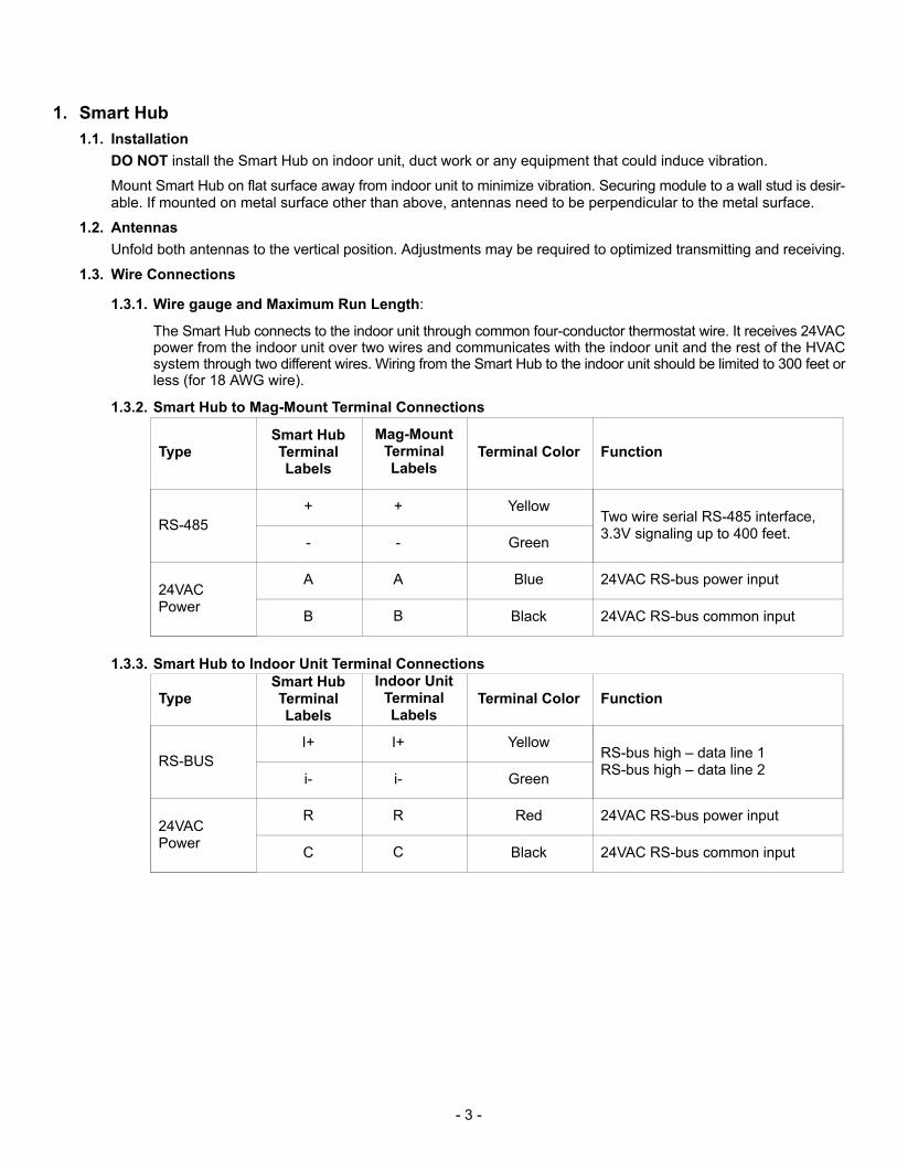
1.3.2. Smart Hub to Mag-Mount Terminal Connections
TypeSmart HubTerminalLabels
Mag-MountTerminalLabels
Terminal Color Function
RS-485
+ + YellowTwo wire serial RS-485 interface,3.3V signaling up to 400 feet.
- - Green
24VACPower
A A Blue 24VAC RS-bus power input
B B Black 24VAC RS-bus common input
1.3.3. Smart Hub to Indoor Unit Terminal Connections
TypeSmart HubTerminalLabels
Indoor UnitTerminalLabels
Terminal Color Function
RS-BUS
I+ I+ YellowRS-bus high – data line 1RS-bus high – data line 2
i- i- Green
24VACPower
R R Red 24VAC RS-bus power input
C C Black 24VAC RS-bus common input
- 4 -
1.4. Troubleshooting
1.4.1. LEDs
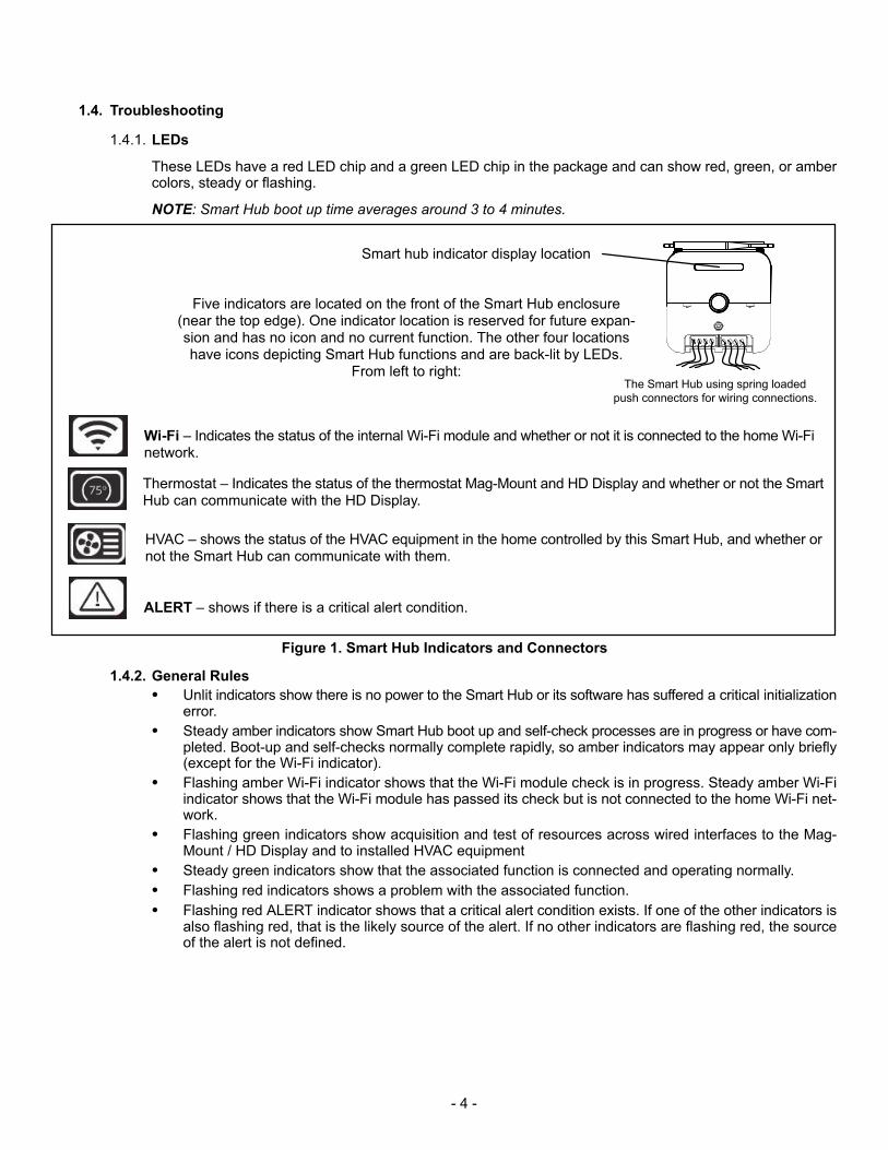
These LEDs have a red LED chip and a green LED chip in the package and can show red, green, or ambercolors, steady or flashing.
NOTE: Smart Hub boot up time averages around 3 to 4 minutes.
The Smart Hub using spring loaded
push connectors for wiring connections.
Five indicators are located on the front of the Smart Hub enclosure(near the top edge). One indicator location is reserved for future expansion and has no icon and no current function. The other four locationshave icons depicting Smart Hub functions and are back-lit by LEDs.
From left to right:
Wi-Fi – Indicates the status of the internal Wi-Fi module and whether or not it is connected to the home Wi-Finetwork.
Thermostat – Indicates the status of the thermostat Mag-Mount and HD Display and whether or not the SmartHub can communicate with the HD Display.
HVAC – shows the status of the HVAC equipment in the home controlled by this Smart Hub, and whether ornot the Smart Hub can communicate with them.
ALERT – shows if there is a critical alert condition.
Smart hub indicator display location
Figure 1. Smart Hub Indicators and Connectors
1.4.2. General Rules
� Unlit indicators show there is no power to the Smart Hub or its software has suffered a critical initializationerror.
� Steady amber indicators show Smart Hub boot up and self-check processes are in progress or have completed. Boot-up and self-checks normally complete rapidly, so amber indicators may appear only briefly(except for the Wi-Fi indicator).
� Flashing amber Wi-Fi indicator shows that the Wi-Fi module check is in progress. Steady amber Wi-Fiindicator shows that the Wi-Fi module has passed its check but is not connected to the home Wi-Fi network.
� Flashing green indicators show acquisition and test of resources across wired interfaces to the Mag-Mount / HD Display and to installed HVAC equipment
� Steady green indicators show that the associated function is connected and operating normally.
� Flashing red indicators shows a problem with the associated function.
� Flashing red ALERT indicator shows that a critical alert condition exists. If one of the other indicators isalso flashing red, that is the likely source of the alert. If no other indicators are flashing red, the sourceof the alert is not defined.

- 5 -
1.4.3. Center Push Button Indicators
The center push button has a RGB (red-green-blue) LED backlight that indicates the Lennox-managed localnetwork communication status of the Smart Hub, and if the Smart Hub is transferring a software image from aflash drive plugged into the USB port. While this LED indicator can show any color, it is currently limited to amber, green, or blue.
When the Smart Hub is in a normal steady state -- when the Smart Hub is in normal day-to-day operation -- thecenter push button backlight shows:
� Steady blue when there is only one Smart Hub in the home and it is not connected to a mobile devicerunning a iComfort® S30 application.
� Steady blue when there is more than one Smart Hub in the home, but this Smart Hub is not connectedto any other Smart Hub.
� Steady blue when the Smart Hub is connected to another Smart Hub in the home through a Lennox-managed local network.
During various Smart Hub transient states -- when the Smart Hub is engaged in a special task that shouldcomplete soon -- the center push button backlight shows:
� Steady amber (briefly) while the Smart Hub conducts self tests and boots up.
� Flashing amber while software or firmware updates for an iComfort® S30 system component or a connected field-upgradable HVAC asset is being transferred from files on a flash drive plugged into the SmartHub USB port.
� Steady blue while the Smart Hub conducts checks on its internal Wi-Fi module and remote HVAC assets.(icon indicators show progress.)
� Flashing green when the Smart Hub is attempting a Lennox-managed local network connection with another Smart Hub in the home or with a mobile device running the iComfort® S30 service maintenanceapplication.
� Steady green when the Smart Hub is connected to a mobile device running the iComfort® S30 servicemaintenance application through a Lennox-managed local network connection. (This is considered atransient state because the mobile device will disconnect from the Lennox-managed network when thetask at hand is complete.)
1.4.4. Wi-Fi Connection
The following terminology is used in this troubleshooting section:
� Router Signal Strength (RSSI). RSSI is an indication of the signal strength of the Wi-Fi router being received by the scanning device (i.e., smart phone). Therefore, the higher the RSSI number (or less negative in some devices), the stronger the signal.
� 802.11a, g and n are wireless networking specification that extends throughput up to 130mbps using the2.4 GHz band.
� Internet Protocol Address (IP address). This is a numerical label assigned to each device (e.g., computer, printer, thermostat) participating in a computer network that uses the Internet Protocol for communication. An IP address serves two principal functions: host or network interface identification and locationaddressing.
� Electromagnetic Interference Causing Poor Connectivity
Locate both the thermostat and router away from other devices that could possibility interfere with wireless communications. Some examples of other devices that could interfere are:
� Microwave ovens
� Wireless cameras
� Portable phones and bases
� Baby monitors
� Wireless speakers
� Bluetooth devices
� Garage door openers
� Neighbor's wireless devices.
To eliminate a possible source of interference, temporally disable any devices and see if Wi-FI performance has improved.
- 6 -
The Smart Hub may be relocated to a new location to obtained a stronger Wi-Fi signal connection to thehome wireless router. The Smart Hub may be place anywhere in the home as long as wiring can be run toit.
� Router Signal Strength (RSSI)
The ideal signal strength range for the iComfort® S30 is -1 to -69 RSSI. The signal strength can be viewedfrom the thermostat interface. Use steps 1
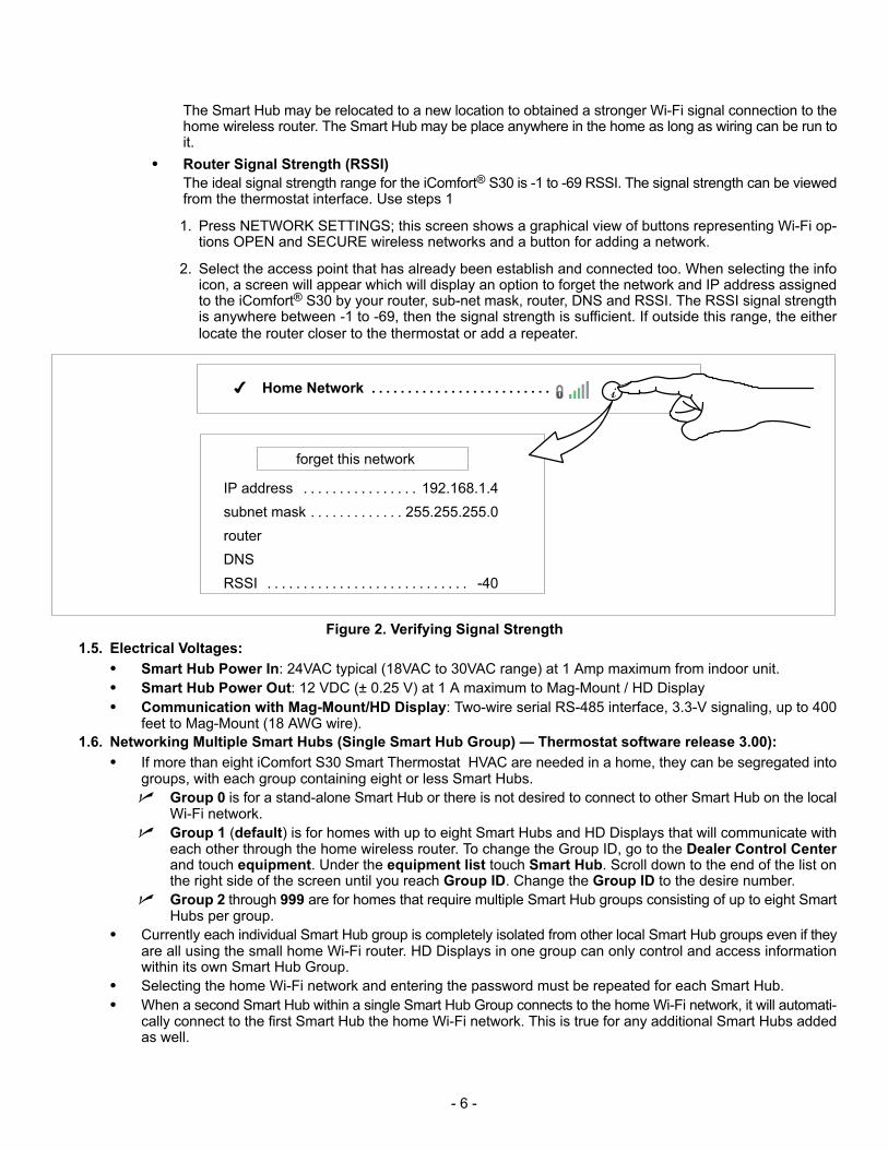
1. Press NETWORK SETTINGS; this screen shows a graphical view of buttons representing Wi-Fi options OPEN and SECURE wireless networks and a button for adding a network.
2. Select the access point that has already been establish and connected too. When selecting the infoicon, a screen will appear which will display an option to forget the network and IP address assignedto the iComfort® S30 by your router, sub-net mask, router, DNS and RSSI. The RSSI signal strengthis anywhere between -1 to -69, then the signal strength is sufficient. If outside this range, the eitherlocate the router closer to the thermostat or add a repeater.
� Home Network . . . . . . . . . . . . . . . . . . . . . . . . .
IP address 192.168.1.4. . . . . . . . . . . . . . . .
subnet mask 255.255.255.0. . . . . . . . . . . . .
router
DNS
RSSI -40. . . . . . . . . . . . . . . . . . . . . . . . . . . .
i
forget this network
Figure 2. Verifying Signal Strength
1.5. Electrical Voltages:
� Smart Hub Power In: 24VAC typical (18VAC to 30VAC range) at 1 Amp maximum from indoor unit.
� Smart Hub Power Out: 12 VDC (± 0.25 V) at 1 A maximum to Mag-Mount / HD Display
� Communication with Mag-Mount/HD Display: Two-wire serial RS-485 interface, 3.3-V signaling, up to 400feet to Mag-Mount (18 AWG wire).
1.6. Networking Multiple Smart Hubs (Single Smart Hub Group) — Thermostat software release 3.00):
� If more than eight iComfort S30 Smart Thermostat HVAC are needed in a home, they can be segregated intogroups, with each group containing eight or less Smart Hubs.
� Group 0 is for a stand-alone Smart Hub or there is not desired to connect to other Smart Hub on the localWi-Fi network.
� Group 1 (default) is for homes with up to eight Smart Hubs and HD Displays that will communicate witheach other through the home wireless router. To change the Group ID, go to the Dealer Control Centerand touch equipment. Under the equipment list touch Smart Hub. Scroll down to the end of the list onthe right side of the screen until you reach Group ID. Change the Group ID to the desire number.
� Group 2 through 999 are for homes that require multiple Smart Hub groups consisting of up to eight SmartHubs per group.
� Currently each individual Smart Hub group is completely isolated from other local Smart Hub groups even if theyare all using the small home Wi-Fi router. HD Displays in one group can only control and access informationwithin its own Smart Hub Group.
� Selecting the home Wi-Fi network and entering the password must be repeated for each Smart Hub.
� When a second Smart Hub within a single Smart Hub Group connects to the home Wi-Fi network, it will automatically connect to the first Smart Hub the home Wi-Fi network. This is true for any additional Smart Hubs addedas well.
- 7 -
Limitations in software release 3.00):
From a single HD display, the following functions can not be controlled or viewed when interacting with other SmartHub within the same Smart Hub group.
� Away Mode
� Weather
� Date and Time
� Notifications
Advantages:
The isolation between groups may be used to good advantage if there is some compelling reason that an HD Displayin one part of the home should not be able to adjust the set point of a system elsewhere in the home. Assigning thesystems to two different Smart Hub Groups would allow this. An example of this might be to isolate the system in themaster suite or a guest bedroom from the HD Display in the children's area. The homeowner iComfort S30 mobileapplication is able to see and interact with all Smart Hubs installed in the home even if they are spread among severalgroups.
2. Mag-Mount
2.1. Mounting to 2x4 Electrical J-Box
2.1.1. Short Term Recommendation
Use Honeywell back plate from LPP store part # X5392.
2.1.2. Back plate - Long Term:
We will enlarge the existing back plate to cover 2”x 4” J box and replacement of larger stats with the iComfortS30
2.1.3. Wiring Connections
2.1.3.1. Wire gauge and Maximum Run Length: The Smart Hub connects to the indoor unit throughcommon four-conductor thermostat wire. It receives 24VAC power from the indoor unit over twowires and communicates with the indoor unit and the rest of the HVAC system through two different wires. Wiring from the Smart Hub to the indoor unit should be limited to 300 feet or less (for18 AWG wire).
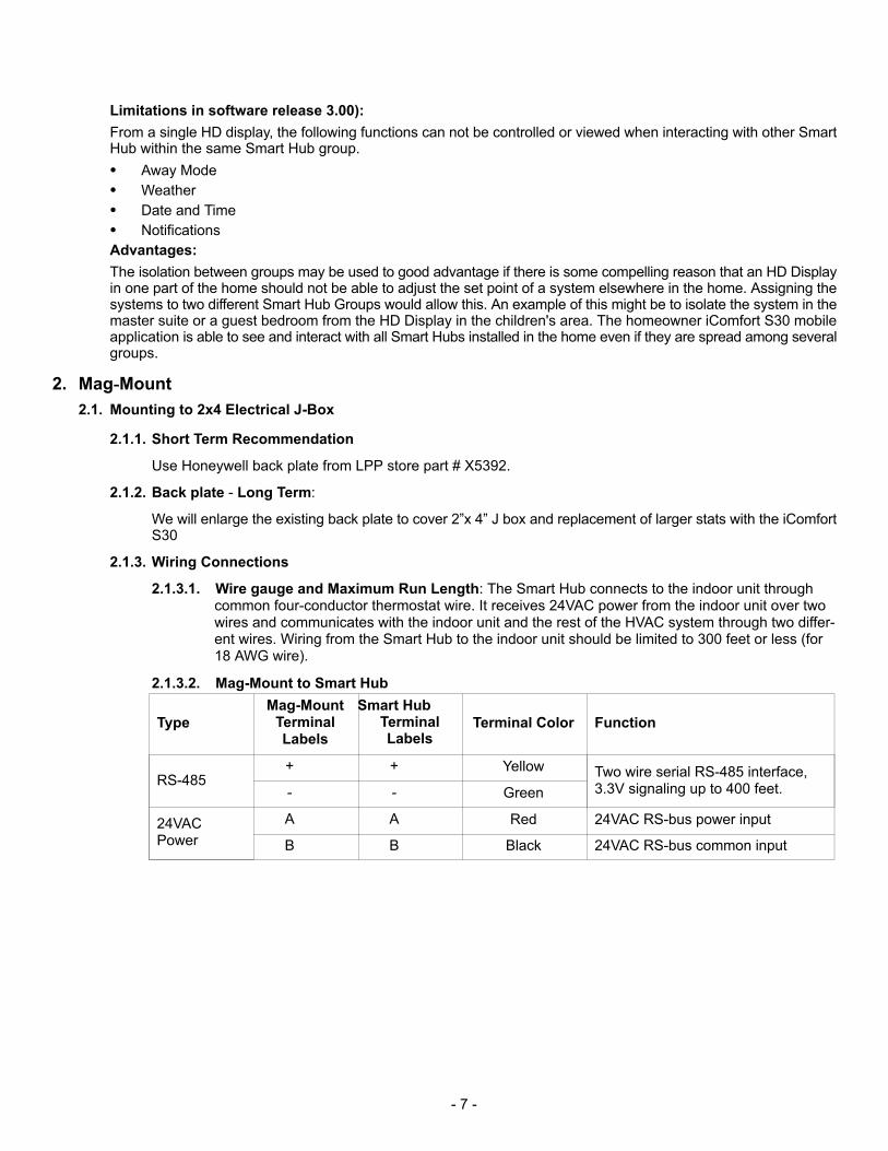
2.1.3.2. Mag-Mount to Smart Hub
Type
Mag-MountTerminalLabels
Smart HubTerminalLabels
Terminal Color Function
RS-485+ + Yellow Two wire serial RS-485 interface,
3.3V signaling up to 400 feet.- - Green
24VACPower
A A Red 24VAC RS-bus power input
B B Black 24VAC RS-bus common input
- 8 -
2.2. Troubleshooting
2.2.1. LED:
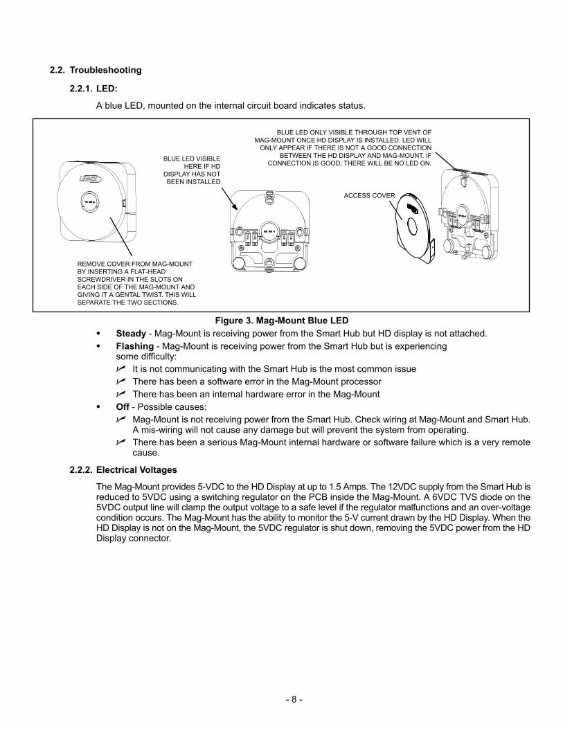
A blue LED, mounted on the internal circuit board indicates status.
REMOVE COVER FROM MAG-MOUNT
BY INSERTING A FLAT-HEAD
SCREWDRIVER IN THE SLOTS ON
EACH SIDE OF THE MAG-MOUNT AND
GIVING IT A GENTAL TWIST. THIS WILL
SEPARATE THE TWO SECTIONS.
ACCESS COVER
BLUE LED VISIBLE
HERE IF HD
DISPLAY HAS NOT
BEEN INSTALLED
BLUE LED ONLY VISIBLE THROUGH TOP VENT OF
MAG-MOUNT ONCE HD DISPLAY IS INSTALLED. LED WILL
ONLY APPEAR IF THERE IS NOT A GOOD CONNECTION
BETWEEN THE HD DISPLAY AND MAG-MOUNT. IF
CONNECTION IS GOOD, THERE WILL BE NO LED ON.
Figure 3. Mag-Mount Blue LED
� Steady - Mag-Mount is receiving power from the Smart Hub but HD display is not attached.
� Flashing - Mag-Mount is receiving power from the Smart Hub but is experiencingsome difficulty:
� It is not communicating with the Smart Hub is the most common issue
� There has been a software error in the Mag-Mount processor
� There has been an internal hardware error in the Mag-Mount
� Off - Possible causes:
� Mag-Mount is not receiving power from the Smart Hub. Check wiring at Mag-Mount and Smart Hub.A mis-wiring will not cause any damage but will prevent the system from operating.
� There has been a serious Mag-Mount internal hardware or software failure which is a very remotecause.
2.2.2. Electrical Voltages
The Mag-Mount provides 5-VDC to the HD Display at up to 1.5 Amps. The 12VDC supply from the Smart Hub isreduced to 5VDC using a switching regulator on the PCB inside the Mag-Mount. A 6VDC TVS diode on the5VDC output line will clamp the output voltage to a safe level if the regulator malfunctions and an over-voltagecondition occurs. The Mag-Mount has the ability to monitor the 5-V current drawn by the HD Display. When theHD Display is not on the Mag-Mount, the 5VDC regulator is shut down, removing the 5VDC power from the HDDisplay connector.
- 9 -
2.2.3. Troubleshooting with Display Removed
Check for 12VDC on Mag-Mount terminals + and -.
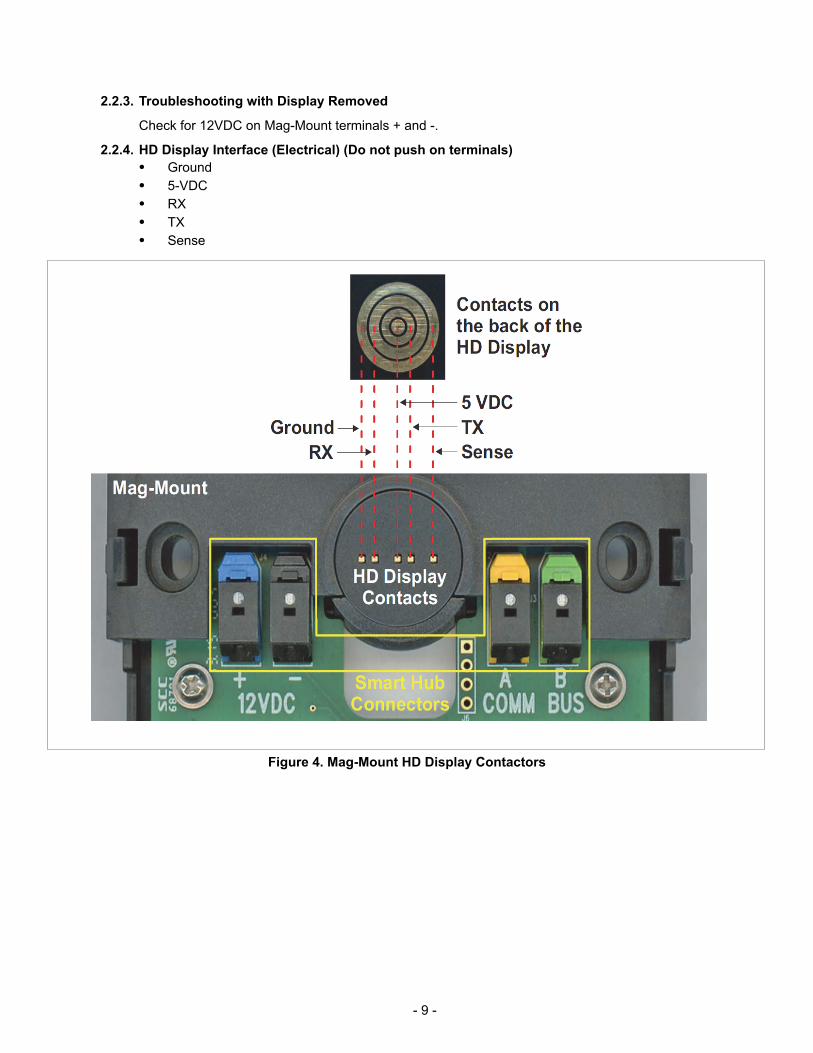
2.2.4. HD Display Interface (Electrical) (Do not push on terminals)
� Ground
� 5-VDC
� RX
� TX
� Sense
Figure 4. Mag-Mount HD Display Contactors
- 10 -
3. Smart Away
If the homeowner has multiple systems in their homes and they wish for one, some or all of them to participate in usingthe Smart Away feature. The changes can be made either directly at each S30 HD Display or using the mobile deviceiComfort Thermostat application. One of the following methods must be performed
3.1. Thermostat
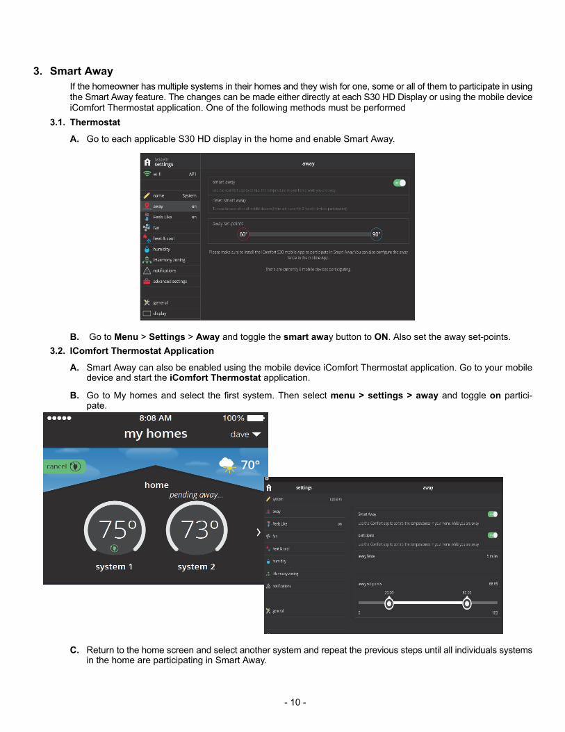
A. Go to each applicable S30 HD display in the home and enable Smart Away.
B. Go to Menu > Settings > Away and toggle the smart away button to ON. Also set the away set-points.
3.2. IComfort Thermostat Application
A. Smart Away can also be enabled using the mobile device iComfort Thermostat application. Go to your mobiledevice and start the iComfort Thermostat application.
B. Go to My homes and select the first system. Then select menu > settings > away and toggle on participate.
C. Return to the home screen and select another system and repeat the previous steps until all individuals systemsin the home are participating in Smart Away.
- 11 -
4. HD Display
4.1. Wi-Fi
4.1.1. Router and Internet Connection:
This is for connecting the S30 Control System to the home wireless network. This settings is disabled by default.
D. From the home screen, go to menu > settings > wi-fi
E. Slide the option to ON to enable Wi-Fi.
If the Access Point is Visible
A. Wi-Fi network will show not connected. Press on not connected.
B. Select a network will be displayed listing all detected networks within range. Selected your home networkby pressing on the network name. DO NOT USE A GUEST OR UNSECURE ACCESS POINT.
C. Assuming that your network is secure, a password will be requested. Enter your password and press jointo continue.
NOTE - If you wish to see the characters you are typing, check show password.
Access Point is Hidden
A. Slide the option to ON to enable Wi-Fi.
B. Wi-Fi network will show not connected. Press on not connected.
C. Select other.
D. The enter new network information screen will appear. Enter the name of the hidden network.
E. Select Security. Options are none, WEP, WPA and WPA2. DO NOT USE A GUEST OR UNSECUREACCESS POINT.
F. Once security type is selected, a password field will appear. Enter the password and press join to continue..
NOTE - If you wish to see the characters you are typing, check show password.
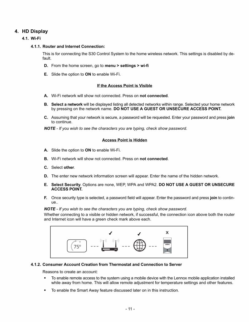
Whether connecting to a visible or hidden network, if successful, the connection icon above both the routerand Internet icon will have a green check mark above each.
� �
4.1.2. Consumer Account Creation from Thermostat and Connection to Server
Reasons to create an account:
� To enable remote access to the system using a mobile device with the Lennox mobile application installedwhile away from home. This will allow remote adjustment for temperature settings and other features.
� To enable the Smart Away feature discussed later on in this instruction.
- 12 -
� To directly communicate to the Dealer any issues the system may be incurring.
� Go to menu > settings > account. This menu allows two options:
NOTE - If setting up new account you will need to first go to the home tab and enter all information therethen to account and create account and enter all information there.
Using Existing Account
If an account has already been created.
A. Use the sign in option to access your account.
B. Enter your email address and password to connect your system to your online account or you can generate a pin number and then enter it in the consumer portal by add another system feature.
Creating a New Account
A. Use this option to create an account. Enter your email and desired password to use. Select create newaccount.
B. The new account screen will appear. Enter your first name, last name and phone number (phone numberis option however if entered, do not use dashes, only numbers).
C. Enter an email address and repeat to verify email address.
D. Create a password under the set password location. Retype the password to verify.
E. Check the box that will allow your dealer to receive service alerts and possibility fix your issue remotely(recommended).
F. Check that you agreed to the Lennox EULA. Press on LENNOX EULA to read the end-user license agreement.
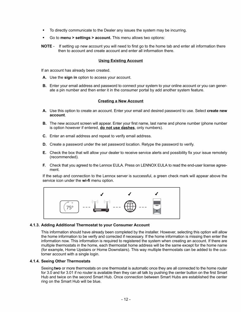
If the setup and connection to the Lennox server is successful, a green check mark will appear above theservice icon under the wi-fi menu option.
� � �
4.1.3. Adding Additional Thermostat to your Consumer Account
This information should have already been completed by the installer. However, selecting this option will allowthe home information to be verify and corrected if necessary. If the home information is missing then enter theinformation now. This information is required to registered the system when creating an account. If there aremultiple thermostats in the home, each thermostat home address will be the same except for the home name(for example, Home Upstairs or Home Downstairs). This way multiple thermostats can be added to the customer account with a single login.
4.1.4. Seeing Other Thermostats
Seeing two or more thermostats on one thermostat is automatic once they are all connected to the home routerfor 3.0 and for 3.01 if no router is available then they can all talk by pushing the center button on the first SmartHub and twice on the second Smart Hub. Once connection between Smart Hubs are established the centerring on the Smart Hub will be blue.
- 13 -
4.2. Ramp, Sag, and Power interruption
Display (thermostat) will indicate error “unable to communicate with Smart Hub”. This pop-up will be displayed forthree minutes which will cause the watchdog to reset the display after three minutes.
� All will recover fine after the reset.
� This whole process will take between 5 – 6 minutes.
� During this test and sometimes also noticeable when manually un-powering and powering the Smart Hub duringtest setups, dashes appear on the display instead of the ambient temperature reading. The dashes will remainon the display for approximately two minutes. After the wait period has ended the display will recover fully.
4.3. Electrical Discharge
Display will indicate error “unable to communicate with Smart Hub”. This pop up will be on the display for 3 minuteswhich will cause the watchdog to reset the Display after three minutes. All will recover fine after the reset. This wholeprocess took between 5 – 6 minutes.
4.4. Screen Locks Up or Goes Blank
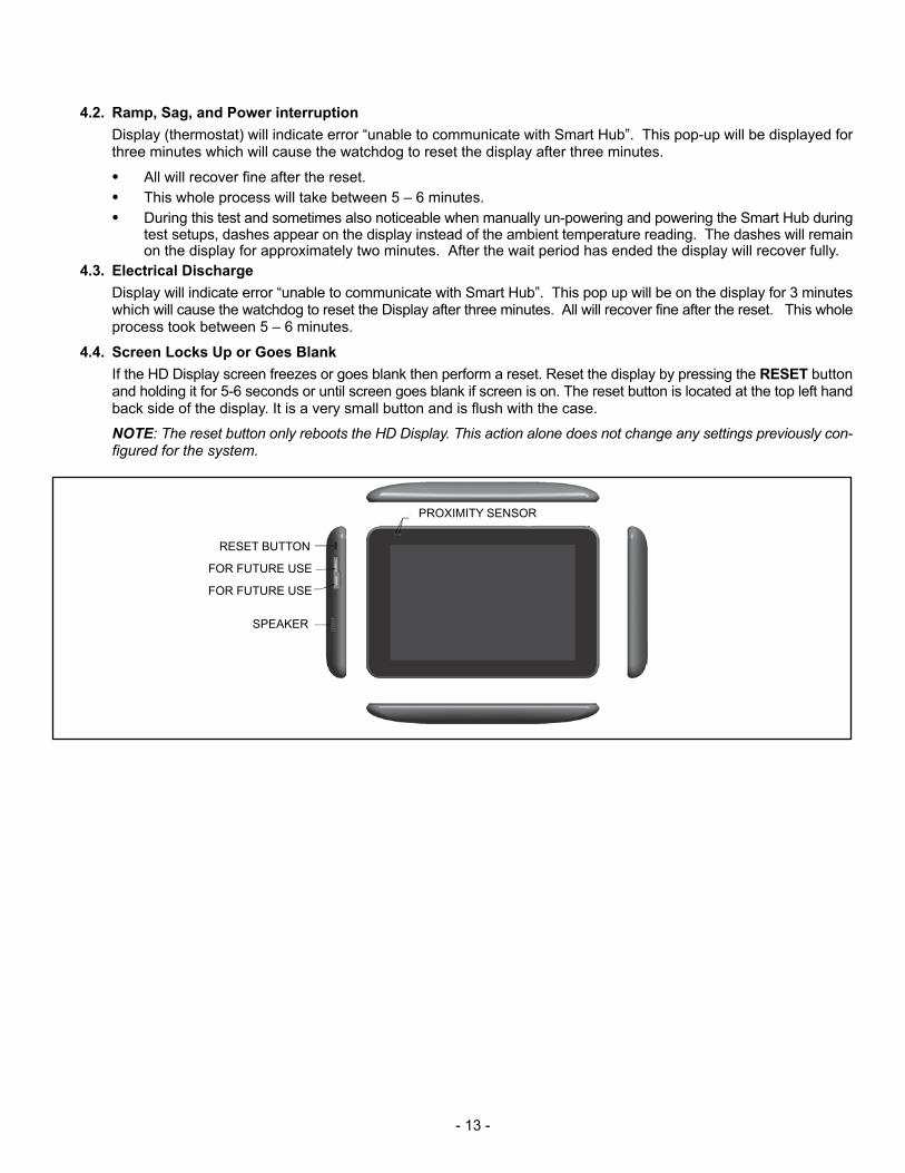
If the HD Display screen freezes or goes blank then perform a reset. Reset the display by pressing the RESET buttonand holding it for 5-6 seconds or until screen goes blank if screen is on. The reset button is located at the top left handback side of the display. It is a very small button and is flush with the case.
NOTE: The reset button only reboots the HD Display. This action alone does not change any settings previously configured for the system.
PROXIMITY SENSOR
RESET BUTTON
SPEAKER
FOR FUTURE USE
FOR FUTURE USE

- 14 -
5. Dealer Portal
5.1. Spoofing
Dealer: Using your DaveNet dealer account, go to the iComfort tab and view all of your iComfort Wi-Fi & S30 customers. Select the iComfort S30 customer whose account you are wanting access too and select it. The customer’saccount will open and you will be able to see their system alerts and a tab for their equipment and if they have givenremote in permission you will see remote in button under the S30 home screen. This remote in function gives you theability to make changes and do test from the Dealer Control Center in the S30.
FTC: Using your login information and accessing iComfort you can spoof the dealers account by putting in the dealernumber. Using the dealer spoofing account number will allow you access to all customers assigned to that dealer. Youwill be able to view and remote into a customer’s account just like the dealer can if the homeowner has given permission to do so.
5.2. Remote View and Control:
Dealer will only be able to remote view or control dealer control center section and configurable parameters only ifDealer Remote View and Control has been enabled at the homeowner system.
A. Go to menu > system > general > dealer info
B. Select dealer access.
C. Enable Remote View by toggling to ON.
D. Enable Remote Control by selecting ON.
6. Creating Consumer Portal Account
This procedures allows the creation of a consumer account using the customer portal instead of at the thermostat.
6.1. Setting Up Account
A. Go to the consumer portal website.
B. Select sign up.
C. Enter all required account info, login, password and enable or disable email updates. For security purposes typethe code that is displayed in the provided box.
- 15 -
D. Check the if you agree to the Lennox EULA.
E. Select sign up. A pop-up will appear indicating you have successfully created your account. Select OK tocontinue.
F. Creation of account is completed.
6.2. Adding System to Consumer Account
A. Login into the consumer portal.
B. From my homes screen, select the email address located in the upper right hand corner of the screen.
C. An option to add icomfort is available. Select icomfort and enter the pin number for the applicable system located in the home. A pin number can be created from the HD Display. From the home screen, go to menu > settings> account and select generate pin number.
D. Enter the pin number and press add.
E. Complete the information under the add icomfort screen (home name, country, address, city, state and zip code.Once completed, press done to continue.
NOTE - If there are multiple systems in the home, then the home name must be unique for each systemadded to the consumer portal account.
F. Your system should appear momentary on the consumer portal screen.
7. Removing System from your Consumer Portal Account
A system can be removed using either the Consumer Portal or directly from the HD Display. There are two methods that areavailable to remove the system, either remove home or move out:
NOTE - If you have given your dealer remote in access, they will no longer be able to remotely access your system.
7.1. Remove Home
A. Go to the consumer portal website or to the HD display that controls the system to be removed.
B. Go to menu > settings > home info and select remove home.
C. A critical warning notification will appears confirming the action, press yes to remove the home (system).
7.2. Move Out
In firmware version 3.0, this feature works exactly like the remove home selection.
NOTE - If you have given your dealer remote in access, they will no longer be able to remotely accessyour system.
A. Go to the consumer portal website or to the HD display that controls the system to be removed.
B. Go to menu > settings > account and select move out.
C. A critical warning notification will appears confirming the action, press yes to remove the home (system).
- 16 -
8. IComfort® Mobile Setup Application
8.1. Operating System Requirements
Dealer commissioning application (iComfort® Mobile Setup) is available for both IOS 6.0 and higher (App Store) andAndroid 4.1 and higher (Google Play).
8.2. Commissioning
To commission a system using the iComfort® Mobile Setup Application perform the following:
NOTE - It is recommend that when using the iComfort® Mobile Setup application to commission the system, remove
the HD Display from the Mag-Mount before starting. Once commissioning is completed, reattached the HD Display to
the Mag-Mount.
A. Download and install the iComfort® Mobile Setup Application.
B. Go to the Smart Hub and press the center Lennox button once.
C. The center ring LED will start blinking green for two minutes. During that time the Smart Hub will broadcast itsWi-Fi identifier (SSID).
D. Go to your mobile device's Wi-Fi connection tool and locate the Smart Hub Wi-Fi broadcast identifier. The identifier (SSID) is Direct E300-5200 for example.
NOTE - Refer to your mobile device's owners manual on how to use your Wi-Fi Connection tool.
E. To connect to the Smart Hub use the last eight digits of the Smart Hub SSID as the password (exampleE3005200).
F. Once connected to the mobile device the Smart Hub center ring LED turns solid green.
G. Start the iComfort Mobile Setup Application and make sure you connect to the correct Smart hub by checkingthe serial number
NOTE - The serial number check is only needed if multiple Smart Hubs are shown. For example if you have threesystems and have completed commissioning of two and while on third unit, the other two Smart hubs connectiondata is still listed in the iComfort Mobile Setup Application. If you chose the wrong one it will not connect because itwould have already stopped broadcasting its connection signal.
H. Press the remote in tab on the iComfort® Mobile Setup Application home screen. This will take you to the commissioning screen.
NOTE - If the system has not been commissioned it will go to commissioning screen. If the system has already
been commissioned it will go to dealer control center.
I. Once the commissioning is completed, exit the iComfort® Mobile Setup Application.
J. Go to the mobile device's Wi-Fi tool and manually disconnect from the Smart Hub. Or if there is no activity afterthree minutes the application will automatically disconnect from the Smart Hub.
K. Once disconnected the Smart Hub LED will return to a solid blue.
- 17 -
L. Once you are done commissioning the system using the Mobile Dealer Application, go the the HD Display andpress the reset button. This will allow the commissioning information stored in the Smart Hub to be downloadedto the HD Display.
NOTE - If the connection between the iComfort Mobile Setup Application and Smart Hub is idle for 15 minutes, theSmart Hub will auto-disconnect from the mobile device. Repeat procedures to reconnect.
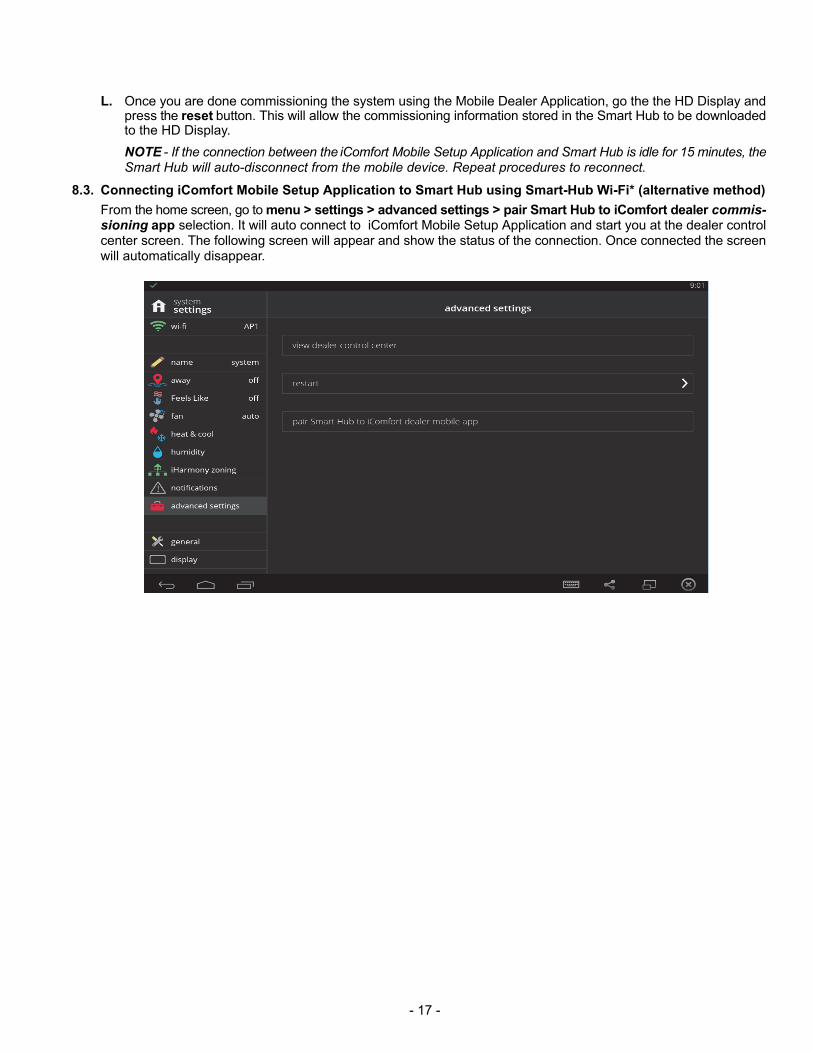
8.3. Connecting iComfort Mobile Setup Application to Smart Hub using Smart-Hub Wi-Fi* (alternative method)
From the home screen, go to menu > settings > advanced settings > pair Smart Hub to iComfort dealer commissioning app selection. It will auto connect to iComfort Mobile Setup Application and start you at the dealer controlcenter screen. The following screen will appear and show the status of the connection. Once connected the screenwill automatically disappear.
- 18 -
8.4. Service
To use Lennox iComfort® Mobile Setup Application as a service tool the commissioning of the system must have already been completed.
A. Download and install the iComfort® Mobile Setup Application if not already installed.
B. Go to the Smart Hub and press the center Lennox button once.
C. The center ring LED will start blinking green for two minutes. During that time the Smart Hub will broadcast itsWi-Fi identifier (SSID).
D. If this is the first time connecting to the target Smart Hub then go to your mobile device's Wi-Fi connection tooland locate the Smart Hub Wi-Fi broadcast identifier. The identifier (SSID) is Direct E300-5200 for example. Ifyour mobile device had already connected previously to the target Smart Hub, then select the applicable SmartHub SSID on the list and skip to step F.
NOTE - Refer to your mobile device's owners manual on how to use your Wi-Fi Connection tool.
E. To connect to the Smart Hub use the last eight digits of the Smart Hub SSID as the password (E3005200).
F. Once connected to the mobile device the Smart Hub center ring LED turns solid green.
G. Start the iComfort® Mobile Setup Application and make sure you connected to the correct Smart hub by checkingthe serial number and pushing on the displayed Smart Hub.
H. Press the remote in tab on the iComfort® Mobile Setup Application home screen. This will take you to the dealercontrol center.
I. Once servicing is completed, exit the iComfort® Mobile Setup Application.
J. Go to the mobile device's Wi-Fi tool and manually disconnect from the Smart Hub.
K. Once disconnected or after three minutes of inactivity the Smart Hub LED turns to a solid blue.
NOTE - If the connection between the iComfort® Mobile Setup Application and Smart Hub is idle for 15 minutes, theSmart Hub will auto-disconnect from the mobile device. Repeat entire procedure to reconnect.
- 19 -
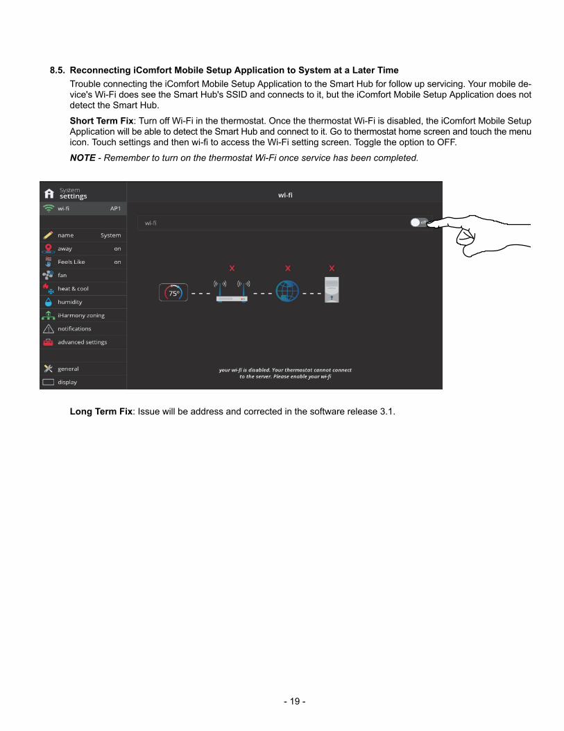
8.5. Reconnecting iComfort Mobile Setup Application to System at a Later Time
Trouble connecting the iComfort Mobile Setup Application to the Smart Hub for follow up servicing. Your mobile device's Wi-Fi does see the Smart Hub's SSID and connects to it, but the iComfort Mobile Setup Application does notdetect the Smart Hub.
Short Term Fix: Turn off Wi-Fi in the thermostat. Once the thermostat Wi-Fi is disabled, the iComfort Mobile SetupApplication will be able to detect the Smart Hub and connect to it. Go to thermostat home screen and touch the menuicon. Touch settings and then wi-fi to access the Wi-Fi setting screen. Toggle the option to OFF.
NOTE - Remember to turn on the thermostat Wi-Fi once service has been completed.
Long Term Fix: Issue will be address and corrected in the software release 3.1.
- 20 -
Troubleshooting
1. Wireless Connection between Mobile Device and Smart Hub
Issue: Your mobile device (smart phone or tablet) will not connect to the Smart Hub using the procedures in the installation
and setup guide. Then try the following possible solution.
Solution: Disable mobile data on your device if applicable.
� Android 4.4 - Go to Settings > Wireless & Networks > More > Mobile Networks > Data Enabled and un-checkthis option
� Android 5.x - Go to Settings > Connections > More Networks > Mobile Networks > Mobile Data and uncheckedthis option.
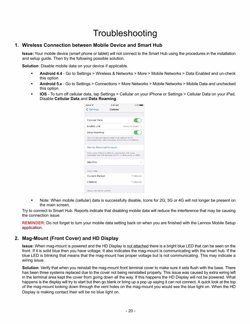
� IOS - To turn off cellular data, tap Settings > Cellular on your iPhone or Settings > Cellular Data on your iPad.Disable Cellular Data and Data Roaming.
� Note: When mobile (cellular) data is successfully disable, Icons for 2G, 3G or 4G will not longer be present onthe main screen.
Try to connect to Smart Hub. Reports indicate that disabling mobile data will reduce the interference that may be causingthe connection issue.
REMINDER: Do not forget to turn your mobile data setting back on when you are finished with the Lennox Mobile Setupapplication.
2. Mag-Mount (Front Cover) and HD Display
Issue: When mag-mount is powered and the HD Display is not attached there is a bright blue LED that can be seen on thefront. If it is solid blue then you have voltage. It also indicates the mag-mount is communicating with the smart hub. If theblue LED is blinking that means that the mag-mount has proper voltage but is not communicating. This may indicate awiring issue.
Solution: Verify that when you reinstall the mag-mount front terminal cover to make sure it sets flush with the base. Therehas been three systems replaced due to the cover not being reinstalled properly. This issue was caused by extra wiring leftin the terminal area kept the cover from going down all the way. If this happens the HD Display will not be powered. Whathappens is the display will try to start but then go blank or bring up a pop up saying it can not connect. A quick look at the topof the mag-mount looking down through the vent holes on the mag-mount you would see the blue light on. When the HD
Display is making contact their will be no blue light on.
- 21 -
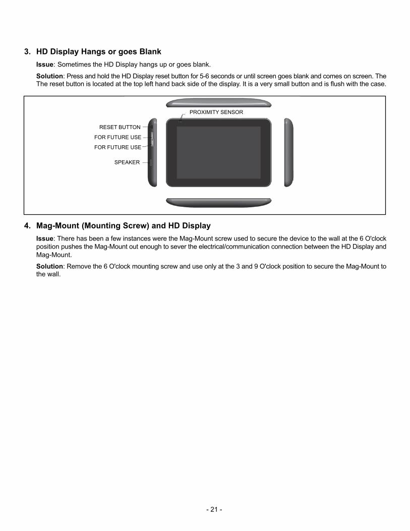
3. HD Display Hangs or goes Blank
Issue: Sometimes the HD Display hangs up or goes blank.
Solution: Press and hold the HD Display reset button for 5-6 seconds or until screen goes blank and comes on screen. TheThe reset button is located at the top left hand back side of the display. It is a very small button and is flush with the case.
PROXIMITY SENSOR
RESET BUTTON
SPEAKER
FOR FUTURE USE
FOR FUTURE USE
4. Mag-Mount (Mounting Screw) and HD Display
Issue: There has been a few instances were the Mag-Mount screw used to secure the device to the wall at the 6 O'clock
position pushes the Mag-Mount out enough to sever the electrical/communication connection between the HD Display and
Mag-Mount.
Solution: Remove the 6 O'clock mounting screw and use only at the 3 and 9 O'clock position to secure the Mag-Mount tothe wall.