charmed: a multi-objective co-synthesis framework for ... · charmed: a multi-objective...
TRANSCRIPT
CHARMED: A Multi-objective Co-synthesis Framework forMulti-mode Embedded Systems
Vida Kianzad, Shuvra S. BhattacharyyaECE Department and Institute for Advanced Computer Studies
University of Maryland, College Park, MD 20742vida, [email protected]
Abstract
In this paper, we present a modular co-synthesis framework called CHARMED that solvesthe problem of hardware-software co-synthesis of periodic, multi-mode, distributed, embed-ded systems. In this framework we perform the synthesis under several constraints whileoptimizing for a set of objectives. We allow the designer to fully control the performanceevaluation process, constraint parameters, and optimization goals. Once the synthesis isperformed, we provide the designer a non-dominated set (Pareto front) of implementationson streamlined architectures that are in general heterogeneous and distributed. We alsoemploy two different techniques, namely clustering and parallelization, to reduce the com-plexity of the solution space and expedite the search. The experimental results demonstratethe effectiveness of the CHARMED framework in computing efficient co-synthesis solutionswithin a reasonable amount of time.
1. Introduction
Modern embedded systems must increasingly accommodate dynamically changing oper-ating environments, high computational requirements, flexibility (e.g., for the emergence ofnew standards and services), and tight time-to-market windows. Such trends and the ever-increasing design complexity of embedded systems have challenged designers to replacetraditional ad-hoc approaches with more efficient techniques such as hardware-software(HW-SW) co-synthesis. HW-SW co-synthesis is the automated process of concurrentlydefining the hardware and software portions of an embedded system. Current and emerg-ing embedded systems often involve multiple application subsystems. Such applicationsmay either run concurrently (single-mode) or in a mutually exclusive fashion, dependingon operational modes (multi-mode). A high-frequency (HF) radio communications systemis one example of such a multi-mode application. It provides a single integrated systemsolution to current and future HF voice and data communications requirements for mili-tary airborne operations. The integrated multi-mode system provides data communicationscapability over HF with modems, video imaging systems, secure voice devices, and dataencryption devices, while continuing to provide voice HF communications capability. Mo-bile telephony, audio decoding systems and video encoding systems are other examples ofmulti-mode applications.
Embedded systems have a variety of constraints and optimization goals such as memory,performance, price, area, power, runtime, number of physical links, etc. to be accommo-
dated. To satisfy such pressing design demands, researchers have shifted from optimalapproaches such as MILP that could handle only a subset of such requirements for smalltask graphs [12] to deterministic heuristic [10][2][7][6] and probabilistic search heuristic[13][4][14] approaches. Many of these approaches only focus on single-mode systems orregard multi-mode systems as multiple single-mode systems and optimize them separately([2] [9] [4] [14]). However, if a task is commonly used across different modes then thesealgorithms may not be able to find the most efficient solutions. Additionally, sharing ofhardware resources among tasks that are not active simultaneously can greatly reduce sys-tem cost. [13], [10] and [7] consider multi-mode applications while optimizing only for asmall set of costs concerning embedded systems. All of the deterministic heuristic methods,convert the multi-dimensional optimization problem to a single-dimensional optimizationproblem by forming a linear combination of the objectives (e.g. power, cost). The maindisadvantage of this technique is that it cannot generate all Pareto-optimal solutions withnon-convex trade-off surfaces, which typically underlie hardware-software co-synthesis sce-narios. Furthermore, forming these linear combinations can be awkward because theyinvolve computing weighted sums of values associated with heterogeneous metrics. Thereis no clear methodology for formulating the linear combinations, and their physical interpre-tation is ambiguous. [13], [4] and [14] employ evolutionary algorithms to overcome the twodrawbacks mentioned above and target significantly larger problem instances. However,they optimize for a significantly smaller set of system costs compared to what we considerin this paper.
Our contribution in this work is as follows: We propose a modular co-synthesis frame-work that synthesizes multi-mode, multi-task embedded systems under a number of hardconstraints; optimizes a comprehensive set of objectives; and provides a set of alternativetrade-off points, generally known as Pareto-optimal solutions. Our framework allows thedesigner to independently configure each dimension of the design evaluation space as anoptimization objective (to be minimized or maximized) or as a constraint (to be satisfied).Furthermore, we employ a pre-processing step of clustering and a parallelization techniqueto expedite the co-synthesis process.
The remainder of this paper is organized as follows: In Section 2 we present prelim-inary concepts and definitions. In Section 3 we describe the implementation details ofour co-synthesis algorithm. In Section 4 we introduce the parallel version of our synthesisalgorithm. We give the experimental results in Section 5 and conclude the paper withSection 6.
2. Preliminaries
2.1 System specification
We represent the embedded system applications that are to be mapped into parallelimplementations in terms of the widely-used task graph model. Each system is characterizedby multiple modes of functionality, where each mode can comprise of several task graphs.The directed acyclic graph Gm,i(V,E) represents the ith task graph of mode m. We assumethere are M different modes of operation and |Gm(V,E)| task graphs in each mode. V isthe set of task nodes, which are in one-to-one correspondence with the computational tasksin the application (V = v1, v2, ..., v|V |) and E is the set of communication edges. Thereis also a period associated with each task graph (π(m, i)). For each mode we form a hyper
task graph GHm(V,E) that consists of copies of high rate task graphs that are active forthe hyper-period given in the following equation:
πH(m) =|Gm(V,E)|−1
LCMi=0
π(m, i). (1)
The target architecture we consider, consists of different processing elements (PE) suchas programmable microprocessors and ASICs and communication resources (CR) such aslinks and buses. PEs and CRs can be of various types. A final solution may be constitutedof multiple instances of each PE or CR type. We represent the number of available PEand CR types by |PEtype| and |CRtype| respectively. Each PE can be characterized by thefollowing attribute vector:
PEattr = [α, κ, µd, µi, ℘idle]T , (2)
where α denotes the area of the processor, κ denotes the price of the processor, µd denotesthe size of data memory, µi denotes the instruction memory size and ℘idle denotes the idlepower consumption of the processor. µi = 0 for ASICs. Each CR also has an attributevector:
CRattr = [℘, ℘idle, ϑ]T , (3)
where ℘ denotes the average power consumption per each unit of data to be transferred,℘idle denotes idle power consumption and ϑ denotes the worst case transmission rate orspeed per each unit of data. Each task is also characterized by a set of attributes given inthe following equation:
Vattr = [type, µi,WCET, ℘avg]T , (4)
where type denotes the type of the task or its functionality, and µi denotes the amountof instruction memory required to store the task. WCET and ℘avg denote the worst-caseexecution time and average power consumption, respectively. These values depend on thePE the task is running on. Task-PE relations are provided in two matrices ΓV and ΦV ofsize |Vtype| × |PEtype|, where |Vtype| denotes the number of available task types. Each edgeis also characterized by a single attribute given in the following equation:
Eattr = [δ], (5)
where δ denotes the size of data communicated in terms of the data unit used to characterizeCRs. Once the edge is assigned to a CR, the worst case communication time and averagepower consumption can be computed using the corresponding CRattr.
2.2 Problem statement
The co-synthesis problem considered in this paper is defined as the problem of optimallymapping the task-level specification of the embedded system onto a heterogeneous hard-ware software architecture. The optimization goal is to find a set of implementations thatsimultaneously minimize multiple objectives for which the corresponding objective vectorscannot be improved in any dimensions without degradation in another. An implementationis described by selection of a set of processing elements (PE) and communication resources(CR) (allocation), mapping of the application onto the selected architecture (assignment)and scheduling each task and data communication on the system resources. Each imple-mentation, represented by solution vector ~x, is evaluated with respect to a set of objectives
that are as follows: area (α(~x)), price (κ(~x)), number of links (`n(~x)), memory require-ment of each PE (−→µ (~x)), power consumption (℘(~x)) and parallel-time or completion-time(τpar(~x)).
Initially all of these goals are defined explicitly as separate optimization criteria, however,our framework allows the designer to formulate any of these goals as a constraint, e.g., thatthe size of the system must not exceed given dimensions. The algorithm always takes the up-per bound (not to be violated if the optimization goal is formulated as a constraint) for eachoptimization goal as an input. However, the input vector Ω0 = [α0, κ0, `n0 ,
−→µ 0, ℘0, τpar0]
will determine the optimization/constraint setting. An entry of 0 means strictly optimiza-tion, an entry of 1 means formulate as a constraint and an entry of 2 means optimizewhile satisfying the constraint. An entry of −1 means to discard that goal for the currentproblem instance. For example Ω0 = [α0, κ0, `n0 ,
−→µ 0, ℘0, τpar0] = [0, 0, 1,−1, 0, 2] configures
CHARMED to find an implementation such that it minimizes the area, dollar cost, powerconsumption and parallel-time; meets the deadline; and does not exceed the given numberof inter-processor links.
2.3 Evolutionary multi-objective optimization
The complex, combinatorial nature of the co-synthesis problem and the need for simul-taneous optimization of several incommensurable and often competing objectives has ledmany researchers to experiment with evolutionary algorithms (EAs) as a solution method.EAs seem to be especially suited to multi-objective optimization as due to their inher-ent parallelism, they have the potential to capture multiple Pareto-optimal solutions in asingle simulation run and may exploit similarities of solutions by recombination. Hence,we have adapted the Strength Pareto Evolutionary Algorithm (SPEA), an evolutionaryalgorithm for multi-objective optimization shown to have superiority over other existingmulti-objective EAs [15]. SPEA uses a mixture of established and new techniques in orderto find multiple Pareto-optimal solutions in parallel and it is characterized by
(a) Storing non-dominated solutions externally in a second, continuously updated popula-tion,
(b) Evaluating an individual’s fitness dependent on the number of external non-dominatedpoints that dominate it,
(c) Preserving population diversity using the Pareto dominance relationship, and(d) Incorporating a grouping procedure in order to reduce the non-dominated set without
destroying its characteristics.
The dominance relation used in the SPEA algorithm is defined as follows:Definition 1: Given two solutions a and b and a minimization problem, then a is said todominate b iff
∀i ∈ 1, 2, ..., n : fi(a) ≤ fi(b) ∧
∃j ∈ 1, 2, ..., n : fj(a) < fj(b). (6)
All solutions that are not dominated by another solution are called non-dominated. Thesolutions that are non-dominated within the entire search space are denoted as Paretooptimal and constitute the Pareto-optimal set. SPEA however does not handle constraintsand only concentrates on unconstrained optimization problems. Hence, we have modified
CHARMED
OUTPUT
2. Technology Lib.
MCFA: Task Clustering
CoreEA: Allocation Assignment Scheduling
Performance Evaluation
TerminationCondition notmet
TerminationCondition met
p1
1
2 7
p2
34
p3
5
p4
6
p11
2 7
p2
3 4
p3
56
INPUT1
7
6
2 5
3
4
1. Application Graph
3. Optimization Vector
...GPPs DSPs
ASICsBUSes
...
Parsing
A non-dominated set of implementations
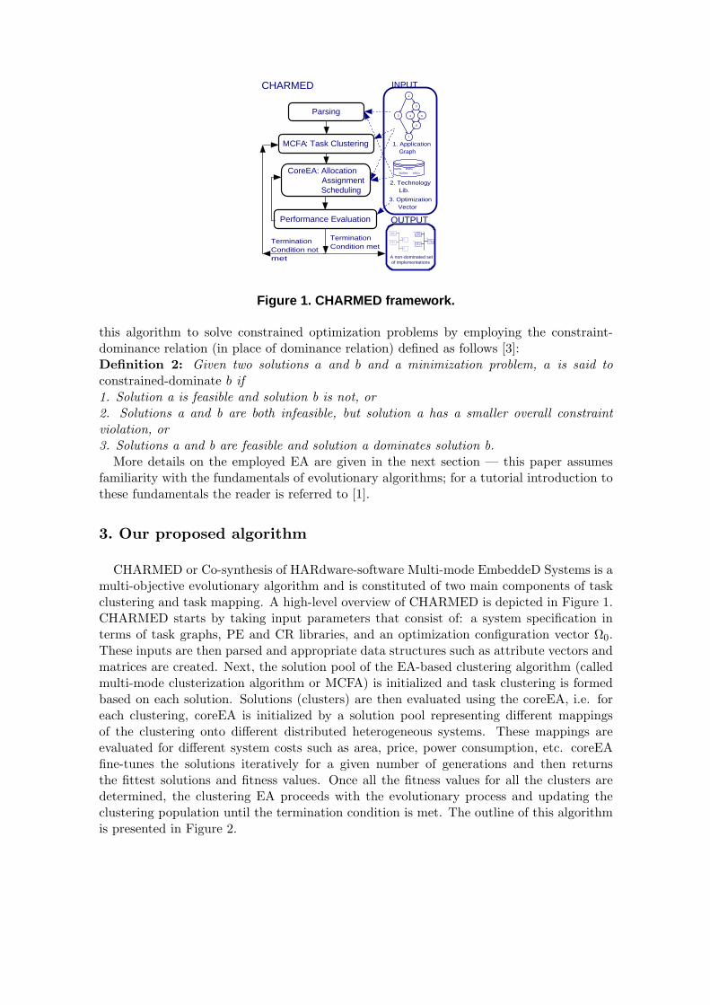
Figure 1. CHARMED framework.
this algorithm to solve constrained optimization problems by employing the constraint-dominance relation (in place of dominance relation) defined as follows [3]:Definition 2: Given two solutions a and b and a minimization problem, a is said toconstrained-dominate b if1. Solution a is feasible and solution b is not, or2. Solutions a and b are both infeasible, but solution a has a smaller overall constraintviolation, or3. Solutions a and b are feasible and solution a dominates solution b.
More details on the employed EA are given in the next section — this paper assumesfamiliarity with the fundamentals of evolutionary algorithms; for a tutorial introduction tothese fundamentals the reader is referred to [1].
3. Our proposed algorithm
CHARMED or Co-synthesis of HARdware-software Multi-mode EmbeddeD Systems is amulti-objective evolutionary algorithm and is constituted of two main components of taskclustering and task mapping. A high-level overview of CHARMED is depicted in Figure 1.CHARMED starts by taking input parameters that consist of: a system specification interms of task graphs, PE and CR libraries, and an optimization configuration vector Ω0.These inputs are then parsed and appropriate data structures such as attribute vectors andmatrices are created. Next, the solution pool of the EA-based clustering algorithm (calledmulti-mode clusterization algorithm or MCFA) is initialized and task clustering is formedbased on each solution. Solutions (clusters) are then evaluated using the coreEA, i.e. foreach clustering, coreEA is initialized by a solution pool representing different mappingsof the clustering onto different distributed heterogeneous systems. These mappings areevaluated for different system costs such as area, price, power consumption, etc. coreEAfine-tunes the solutions iteratively for a given number of generations and then returnsthe fittest solutions and fitness values. Once all the fitness values for all the clusters aredetermined, the clustering EA proceeds with the evolutionary process and updating theclustering population until the termination condition is met. The outline of this algorithmis presented in Figure 2.
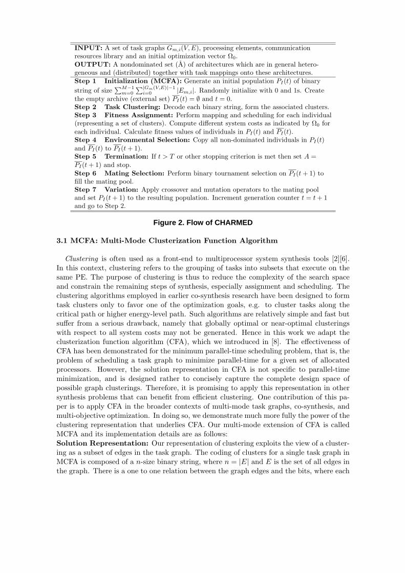
INPUT: A set of task graphs Gm,i(V,E), processing elements, communicationresources library and an initial optimization vector Ω0.OUTPUT: A nondominated set (A) of architectures which are in general hetero-geneous and (distributed) together with task mappings onto these architectures.Step 1 Initialization (MCFA): Generate an initial population PI(t) of binarystring of size
∑M−1m=0
∑|Gm(V,E)|−1i=0 |Em,i|. Randomly initialize with 0 and 1s. Create
the empty archive (external set) PI(t) = ∅ and t = 0.Step 2 Task Clustering: Decode each binary string, form the associated clusters.Step 3 Fitness Assignment: Perform mapping and scheduling for each individual(representing a set of clusters). Compute different system costs as indicated by Ω0 foreach individual. Calculate fitness values of individuals in PI(t) and PI(t).Step 4 Environmental Selection: Copy all non-dominated individuals in PI(t)and PI(t) to PI(t + 1).Step 5 Termination: If t > T or other stopping criterion is met then set A =PI(t + 1) and stop.Step 6 Mating Selection: Perform binary tournament selection on PI(t + 1) tofill the mating pool.Step 7 Variation: Apply crossover and mutation operators to the mating pooland set PI(t + 1) to the resulting population. Increment generation counter t = t + 1and go to Step 2.
Figure 2. Flow of CHARMED
3.1 MCFA: Multi-Mode Clusterization Function Algorithm
Clustering is often used as a front-end to multiprocessor system synthesis tools [2][6].In this context, clustering refers to the grouping of tasks into subsets that execute on thesame PE. The purpose of clustering is thus to reduce the complexity of the search spaceand constrain the remaining steps of synthesis, especially assignment and scheduling. Theclustering algorithms employed in earlier co-synthesis research have been designed to formtask clusters only to favor one of the optimization goals, e.g. to cluster tasks along thecritical path or higher energy-level path. Such algorithms are relatively simple and fast butsuffer from a serious drawback, namely that globally optimal or near-optimal clusteringswith respect to all system costs may not be generated. Hence in this work we adapt theclusterization function algorithm (CFA), which we introduced in [8]. The effectiveness ofCFA has been demonstrated for the minimum parallel-time scheduling problem, that is, theproblem of scheduling a task graph to minimize parallel-time for a given set of allocatedprocessors. However, the solution representation in CFA is not specific to parallel-timeminimization, and is designed rather to concisely capture the complete design space ofpossible graph clusterings. Therefore, it is promising to apply this representation in othersynthesis problems that can benefit from efficient clustering. One contribution of this pa-per is to apply CFA in the broader contexts of multi-mode task graphs, co-synthesis, andmulti-objective optimization. In doing so, we demonstrate much more fully the power of theclustering representation that underlies CFA. Our multi-mode extension of CFA is calledMCFA and its implementation details are as follows:Solution Representation: Our representation of clustering exploits the view of a cluster-ing as a subset of edges in the task graph. The coding of clusters for a single task graph inMCFA is composed of a n-size binary string, where n = |E| and E is the set of all edges inthe graph. There is a one to one relation between the graph edges and the bits, where each
bit represents the presence or absence of the edge in a cluster. Assuming M modes and|Gm(V,E)| task graphs for each mode, the total size of the binary string that would capturethe clustering for all task graphs across different modes is nall =
∑M−1m=0
∑|Gm(V,E)|−1i=0 |Em,i|.
Initial Population: The initial population of MCFA consists of NI (to be set experi-mentally) binary strings that represent different clusterings. Each binary array is initializedrandomly with equal probability for a bit of 1 or 0.
Genetic Operators: We will discuss the crossover and mutation operators in Sec-tion 3.3. For the selection operator we use binary tournament with replacement [1]. Here,two individuals are selected randomly, and the best of the two individuals (according totheir fitness values) is the winner and is used for reproduction. Both winner and loser arereturned to the pool for the next selection operation of that generation.
Fitness Evaluation: Clusterings are evaluated using coreEA, which is described indetail in the next section(3.2).
The key characteristic of MCFA (or CFA) is the natural, binary representation for clus-terings that, unlike previous approaches to clustering in co-synthesis, is not specializedfor one specific optimization objective (e.g., critical path minimization), but rather, canbe configured for different, possibly multi-dimensional, co-synthesis contexts based on howfitness evaluation is performed.
3.2 coreEA: mapping and scheduling
coreEA is the heart of the CHARMED framework and its goal is to find a set of imple-mentations for each member of the MCFA solution pool (or each clustering). It runs oncefor each member. coreEA starts by creating a PE and a CR allocation string for the givensolution (or clustering). The lengths of these string are equal to the number of PE andCR types, respectively. We initialize them such that every cluster and every inter-clustercommunication (ICC) edge has at least one instance of PE or CR that it can execute on.Each entry of the string represents the number of available instances of the associated PEtype. Based on these allocation strings and the numbers of clusters and ICC edges we theninitialize the population of coreEA. Further design details of this EA are as follows:Solution Representation: Solutions in coreEA represent the assignment of clusters toPEs and ICCs to CRs. These assignments are encoded in two different binary matrices,hence each solution is represented with a pair of matrices. Using the allocation arrays wecompute the total number of available PEs (|PEavail|) and CRs (|CRavail|)(including dif-ferent instances of a same type). The assignment matrix for clusters is of size |PEavail| ×|clusters| and for ICCs is of size |CRavail| × |ICC|. |clusters| denotes the number of clus-ters in the solution and |ICC| denotes number of ICC edges. Each column of the cluster(ICC) assignment matrix corresponds to a cluster (ICC) that has to be assigned to a PE(CR). Each row of this matrix corresponds to an available PE (CR). Each column of thePE (CR) assignment matrix possesses exactly one non-zero row that determines the PE(CR) that the cluster (ICC) is assigned to.
Initial Population:The initial population of coreEA consists of NII (to be set experi-mentally) pair of assignment matrices (one for clusters and one for ICCs). For each solution,exactly one 1 is randomly assigned to each column of each assignment matrix.
Genetic Operators: The crossover and mutation operators of coreEA are discussed inSection 3.3. For the selection operator, we use a technique similar to the one described inSection 3.1.
Fitness Evaluation: Each member of the solution pool of coreEA that is a pair ofassignment matrices representing cluster-to-PE and ICC-to-CR mapping, is employed toconstruct a schedule for each clustering. Once the ordering and assignment of each taskis known we calculate other objectives and constraints given in Ω0. Since the modes aremutually exclusive, it is possible to employ scheduling methods that are used for singlemode systems. Scheduling a task graph for a given allocation and for a single mode isa well-known problem which has been extensively studied and for which good heuristicsare available. Hence, we employ a deterministic method that is based on the classic listscheduling heuristic.
Once clusters are mapped and scheduled to the target architecture, we compute differ-ent system costs across different modes and check for constraint violations of individualmodes. Next, using the constrained-dominance relation we calculate the fitness value foreach individual [15]. In certain problems, the non-dominated set can be extremely largeand maintaining the whole set when its size exceeds reasonable bounds is not advantageous.Too many non-dominated individuals might also reduce selection pressure and slow downthe search. Thus, pruning the external set while maintaining its characteristics, before pro-ceeding to the next generation is necessary [15]. The pruning process is based on computingthe phenotypic distance of the objective values. Since the magnitude of each objective cri-terion is quite different, we normalize the distance with respect to each objective function.More formally, for a given objective value f1(~x), the distance between two solutions ~xi and~xj with respect to f1 is normalized as follows:
(f1(~xi)− f1( ~xj))2
(max(f1(t))−min(f1(t)))2 . (7)
For area, price, power consumption and parallel-time, the max(f1(t)) and min(f1(t)) denotethe worst and best case values of the corresponding system cost among all the membersin generation t, respectively. The maximum number of links or max(`n(t)) is computedfrom the maximum possible number of physical inter-processor links for the given graphset Gm,i(V,E) and the processor configuration, i.e.
max(`n(t)) = max(|PEused| × (|PEused| − 1), |Em,i|), (8)
where |Em,i| is the number of edges in the graph. The equation implies that the maximumnumber of inter-processor links that make sense for a network is not necessarily that corre-sponding to a fully connected-network; depending on the number of edges in the graph, thisnumber can be smaller. Minimum number of links is equal to |PEused|−1). The maximumvalue for the memory requirement is equal to the size of data and instruction memory.The minimum value is computed using the smallest amount of memory used among thesolutions in generation t. If optimization goals are formulated as constraints, the maximumvalues are replaced by the given constraint values.
The flow of coreEA is given in Figure 3. coreEA can be employed without the pre-processing step of clustering by simply substituting groups of tasks (clusters) by individualtasks.
3.3 Multi-mode genetic operators
The design of genetic operators for manipulating multi-mode systems requires specialconsiderations that take into account both the global aspects of the systems, while re-
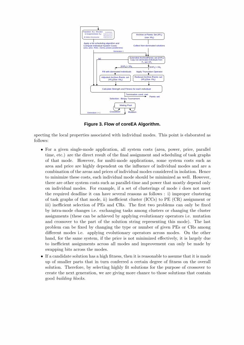
Population (PII) : Allocation& Assignment(size NII)
2D -Matrix Chromosome
Compute Individual System Costs: [area, price, #links , memry, power, parallel-time]
Archive or Pareto Set (XPII)
Extended Archive/Pareto set (XXPII)Copy non-dominated individuals fromP II and XPII
(size XNII)
Collect Non-dominated solutionsApply a list scheduling algorithm and
Reduced Archive /Pareto set(XPII)(Size XNII)
|XXPII| > XNII
Apply Truncation Operator
|XXPII| < XNII
Adjusted Archive /Pareto set (XPII)(Size XNII)
Fill with dominated individuals
NO
Calculate Strength and Fitness for each individual
Mating Pool
Selection : Binary Tournament
Mutation
Pareto setTermination cond. met
0 1 1 0 01 0 0 1 00 0 0 0 1
P1P2P3
c1 c2c3c4 c5
Generation t
Generation t + 1 Crossover
Figure 3. Flow of coreEA Algorithm.
specting the local properties associated with individual modes. This point is elaborated asfollows:
• For a given single-mode application, all system costs (area, power, price, paralleltime, etc.) are the direct result of the final assignment and scheduling of task graphsof that mode. However, for multi-mode applications, some system costs such asarea and price are highly dependent on the influence of individual modes and are acombination of the areas and prices of individual modes considered in isolation. Henceto minimize these costs, each individual mode should be minimized as well. However,there are other system costs such as parallel-time and power that mostly depend onlyon individual modes. For example, if a set of clusterings of mode i does not meetthe required deadline it can have several reasons as follows : i) improper clusteringof task graphs of that mode, ii) inefficient cluster (ICCs) to PE (CR) assignment oriii) inefficient selection of PEs and CRs. The first two problems can only be fixedby intra-mode changes i.e. exchanging tasks among clusters or changing the clusterassignments (these can be achieved by applying evolutionary operators i.e. mutationand crossover to the part of the solution string representing this mode). The lastproblem can be fixed by changing the type or number of given PEs or CRs amongdifferent modes i.e. applying evolutionary operators across modes. On the otherhand, for the same system, if the price is not minimized effectively, it is largely dueto inefficient assignments across all modes and improvement can only be made byswapping bits across the modes.
• If a candidate solution has a high fitness, then it is reasonable to assume that it is madeup of smaller parts that in turn conferred a certain degree of fitness on the overallsolution. Therefore, by selecting highly fit solutions for the purpose of crossover tocreate the next generation, we are giving more chance to those solutions that containgood building blocks.
Host Workstation
PARALLEL CHARMEDGeneration Process
The Internet
Evaluation Process: Wait on Generationt to be evaluated
Workstation 1
1. Construct Clusters2.Map and Schedule3.Compute Fitness4. Return FitnessCoreGA:Allocation Assignment Scheduling
Workstation 2
1. Construct Clusters2.Map and Schedule3.Compute Fitness4. Return FitnessCoreGA:Allocation Assignment Scheduling Workstation N
1. Construct Clusters2.Map and Schedule3.Compute Fitness4. Return FitnessCoreGA:Allocation Assignment Scheduling
...
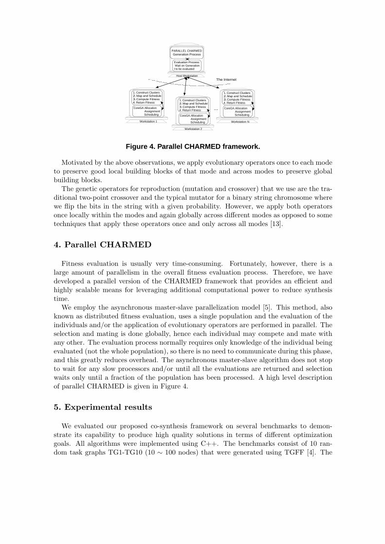
Figure 4. Parallel CHARMED framework.
Motivated by the above observations, we apply evolutionary operators once to each modeto preserve good local building blocks of that mode and across modes to preserve globalbuilding blocks.
The genetic operators for reproduction (mutation and crossover) that we use are the tra-ditional two-point crossover and the typical mutator for a binary string chromosome wherewe flip the bits in the string with a given probability. However, we apply both operatorsonce locally within the modes and again globally across different modes as opposed to sometechniques that apply these operators once and only across all modes [13].
4. Parallel CHARMED
Fitness evaluation is usually very time-consuming. Fortunately, however, there is alarge amount of parallelism in the overall fitness evaluation process. Therefore, we havedeveloped a parallel version of the CHARMED framework that provides an efficient andhighly scalable means for leveraging additional computational power to reduce synthesistime.
We employ the asynchronous master-slave parallelization model [5]. This method, alsoknown as distributed fitness evaluation, uses a single population and the evaluation of theindividuals and/or the application of evolutionary operators are performed in parallel. Theselection and mating is done globally, hence each individual may compete and mate withany other. The evaluation process normally requires only knowledge of the individual beingevaluated (not the whole population), so there is no need to communicate during this phase,and this greatly reduces overhead. The asynchronous master-slave algorithm does not stopto wait for any slow processors and/or until all the evaluations are returned and selectionwaits only until a fraction of the population has been processed. A high level descriptionof parallel CHARMED is given in Figure 4.
5. Experimental results
We evaluated our proposed co-synthesis framework on several benchmarks to demon-strate its capability to produce high quality solutions in terms of different optimizationgoals. All algorithms were implemented using C++. The benchmarks consist of 10 ran-dom task graphs TG1-TG10 (10 ∼ 100 nodes) that were generated using TGFF [4]. The
population size of MCFA and coreEA are 100 and 50. MCFA runs for 1000 generationsand coreEA runs for 500 generations. In case of parallel CHARMED, the fraction of thepopulation that the algorithm waits on, is 80% of the original population, in other wordsonce it receives the results from 80 members (running remotely) it proceeds to the nextgeneration.
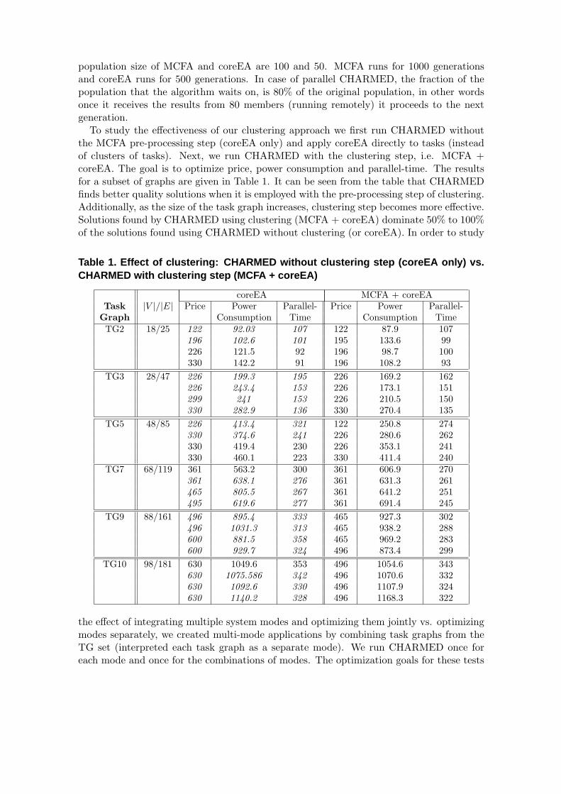
To study the effectiveness of our clustering approach we first run CHARMED withoutthe MCFA pre-processing step (coreEA only) and apply coreEA directly to tasks (insteadof clusters of tasks). Next, we run CHARMED with the clustering step, i.e. MCFA +coreEA. The goal is to optimize price, power consumption and parallel-time. The resultsfor a subset of graphs are given in Table 1. It can be seen from the table that CHARMEDfinds better quality solutions when it is employed with the pre-processing step of clustering.Additionally, as the size of the task graph increases, clustering step becomes more effective.Solutions found by CHARMED using clustering (MCFA + coreEA) dominate 50% to 100%of the solutions found using CHARMED without clustering (or coreEA). In order to study
Table 1. Effect of clustering: CHARMED without clustering step (coreEA only) vs.CHARMED with clustering step (MCFA + coreEA)
coreEA MCFA + coreEATask |V |/|E| Price Power Parallel- Price Power Parallel-
Graph Consumption Time Consumption TimeTG2 18/25 122 92.03 107 122 87.9 107
196 102.6 101 195 133.6 99226 121.5 92 196 98.7 100330 142.2 91 196 108.2 93
TG3 28/47 226 199.3 195 226 169.2 162226 243.4 153 226 173.1 151299 241 153 226 210.5 150330 282.9 136 330 270.4 135
TG5 48/85 226 413.4 321 122 250.8 274330 374.6 241 226 280.6 262330 419.4 230 226 353.1 241330 460.1 223 330 411.4 240
TG7 68/119 361 563.2 300 361 606.9 270361 638.1 276 361 631.3 261465 805.5 267 361 641.2 251495 619.6 277 361 691.4 245
TG9 88/161 496 895.4 333 465 927.3 302496 1031.3 313 465 938.2 288600 881.5 358 465 969.2 283600 929.7 324 496 873.4 299
TG10 98/181 630 1049.6 353 496 1054.6 343630 1075.586 342 496 1070.6 332630 1092.6 330 496 1107.9 324630 1140.2 328 496 1168.3 322
the effect of integrating multiple system modes and optimizing them jointly vs. optimizingmodes separately, we created multi-mode applications by combining task graphs from theTG set (interpreted each task graph as a separate mode). We run CHARMED once foreach mode and once for the combinations of modes. The optimization goals for these tests
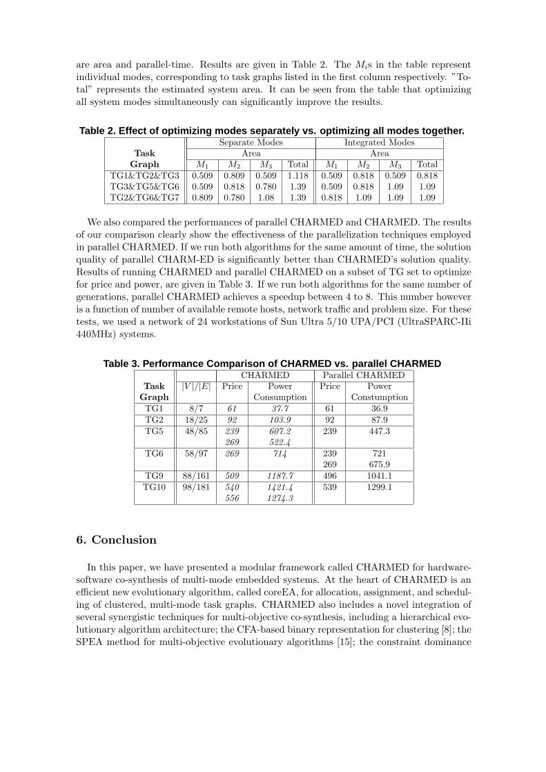
are area and parallel-time. Results are given in Table 2. The Mis in the table representindividual modes, corresponding to task graphs listed in the first column respectively. ”To-tal” represents the estimated system area. It can be seen from the table that optimizingall system modes simultaneously can significantly improve the results.
Table 2. Effect of optimizing modes separately vs. optimizing all modes together.Separate Modes Integrated Modes
Task Area AreaGraph M1 M2 M3 Total M1 M2 M3 Total
TG1&TG2&TG3 0.509 0.809 0.509 1.118 0.509 0.818 0.509 0.818TG3&TG5&TG6 0.509 0.818 0.780 1.39 0.509 0.818 1.09 1.09TG2&TG6&TG7 0.809 0.780 1.08 1.39 0.818 1.09 1.09 1.09
We also compared the performances of parallel CHARMED and CHARMED. The resultsof our comparison clearly show the effectiveness of the parallelization techniques employedin parallel CHARMED. If we run both algorithms for the same amount of time, the solutionquality of parallel CHARM-ED is significantly better than CHARMED’s solution quality.Results of running CHARMED and parallel CHARMED on a subset of TG set to optimizefor price and power, are given in Table 3. If we run both algorithms for the same number ofgenerations, parallel CHARMED achieves a speedup between 4 to 8. This number howeveris a function of number of available remote hosts, network traffic and problem size. For thesetests, we used a network of 24 workstations of Sun Ultra 5/10 UPA/PCI (UltraSPARC-IIi440MHz) systems.
Table 3. Performance Comparison of CHARMED vs. parallel CHARMEDCHARMED Parallel CHARMED
Task |V |/|E| Price Power Price PowerGraph Consumption ConstumptionTG1 8/7 61 37.7 61 36.9TG2 18/25 92 103.9 92 87.9TG5 48/85 239 607.2 239 447.3
269 522.4TG6 58/97 269 714 239 721
269 675.9TG9 88/161 509 1187.7 496 1041.1TG10 98/181 540 1421.4 539 1299.1
556 1274.3
6. Conclusion
In this paper, we have presented a modular framework called CHARMED for hardware-software co-synthesis of multi-mode embedded systems. At the heart of CHARMED is anefficient new evolutionary algorithm, called coreEA, for allocation, assignment, and schedul-ing of clustered, multi-mode task graphs. CHARMED also includes a novel integration ofseveral synergistic techniques for multi-objective co-synthesis, including a hierarchical evo-lutionary algorithm architecture; the CFA-based binary representation for clustering [8]; theSPEA method for multi-objective evolutionary algorithms [15]; the constraint dominance
concepts of Deb et al. [3]; and optionally, the asynchronous master-slave parallelizationmodel [5]. Our framework allows the designer to flexibly control the performance evalua-tion process by configuring design evaluation metrics as optimization goals or constraints,as desired. This flexibility enables the designer to narrow down the search to special regionsof interest. Our parallelization technique, parallel CHARMED, is shown to provide an ef-ficient means for applying additional computational resources to the co-synthesis process.This enables application of CHARMED to large instances of co-synthesis problems.
For future work, we are planning to add a refinement step that uses the possibly sub-optimal solutions generated by the allocation/assignment phase as the starting point forits local search. We will also be looking into another method of parallelizing EAs thatsearches different subspaces of the search space in parallel and is less likely to get trappedin low-quality subspaces.
References
[1] T. Back, U. Hammel, and H.-P. Schwefel, ”Evolutionary computation: comments on the history andcurrent state,” IEEE Transactions on Evolutionary Computation, vol. 1, pp. 3-17, 1997.
[2] B. P. Dave, G. Lakshminarayana, and N. K. Jha, ”COSYN: Hardware-software co-synthesis of het-erogeneous distributed embedded systems,” IEEE Trans. on VLSI Systems, vol. 7, pp. 92104, Mar.1999.
[3] K. Deb, A. Pratap, and T. Meyarivan, ”Constrained test problems for multi-objective evolutionaryoptimization,” First International Conference on Evolutionary Multi-Criterion Optimization, pp 284–298. Springer Verlag, 2001.
[4] R. Dick, D. Rhodes, and W. Wolf, ”TGFF: Task Graphs for Free,” In Proc. Int. Workshop Hard-ware/Software Codesign, P.97-101, March 1998.
[5] D. Goldberg, Genetic Algorithms in Search, Optimization, and Machine Learning, Addison-Wesley,1989.
[6] J. Hou and W. Wolf, ”Process partitioning for distributed embedded systems,” in Proc. of Int. Workshopon Hardware/Software Co-Design, pp. 7076, Mar, 1996.
[7] A. Kalavade and P. A. Subrahmanyam, Hardware/Software Partitiong for Multifunction Systems. IEEETrans. on Computer-Aided Design, 17(9):819836, Sep 1998.
[8] V. Kianzad and S. S. Bhattacharyya, ”Multiprocessor clustering for embedded systems,” Proc. of theEuropean Conference on Parallel Computing, 697-701, Manchester, United Kingdom, August 2001.
[9] H. Oh and S. Ha, ”Hardware-software co-synthesis technique based on heterogeneous multiprocessorscheduling,” in Proc. of Int. Workshop on Hardware/ Software Co-Design, pp. 1831878, May 1999.
[10] H. Oh and S. Ha, ”Hardware-software co-synthesis of multi-mode multi-task embedded systems withreal-time constraints,” in Proc. of the Int. symposium on Hardware/software codesign, pp. 133-138,May 2002.
[11] P. Marwedel and G. Goossens, Code Generation for Embedded Processors. Kluwer Academic Publish-ers, 1995.
[12] S. Prakash and A. Parker, ”SOS: Synthesis of application-specific heterogeneous multiprocessor sys-tems,” J. of Parallel & Distributed Computing, vol. 16, pp. 338351, Dec. 1992.
[13] M. Schmitz, B. Al-Hashimi, and P. Eles, ”A Co-Design Methodology for Energy-Efficient Multi-ModeEmbedded Systems with Consideration of Mode Execution Probabilities,” Proc. Design, Automationand Test in Europe, 2003.
[14] J. Teich, T. Blickle, and L. Thiele, ”An evolutionary approach to system-level synthesis,” in Proc. ofInt. Workshop on Hardware/Software Co-Design, pp. 167 171, Mar. 1997.
[15] E. Zitzler, M. Laumanns, L. Thiele, ”SPEA2: Improving the Strength Pareto Evolutionary Algorithmfor Multiobjective Optimization,” Evolutionary Methods for Design, Optimisation, and Control, pp.95-100, 2002.