characteristics of evaporators - amick racing conditioning/characteristics of... · characteristics...
TRANSCRIPT
Characteristics of Evaporators Roger D. Holder, CM, MSME
10-28-2003 Heat or Energy
In this paper, we will discuss the characteristics of an evaporator coil. The variance of the operational condenses of the system and discusses the different energy in which it operates under.
An evaporator is any heat transfer surface in which a liquid is vaporized for the purpose of removing heat from a refrigerated space or product. Heat is a form of energy. Energy is defined as the capacity for doing work. (First Law of Thermodynamics) The conservation of energy law states that energy can neither be created nor destroyed, but it can change forms. Heat or energy can only be moved, but based on the law for any system, open or closed; there must be an energy balance. Air conditioning and refrigeration systems are balanced systems. The total heat or energy absorbed by the evaporator and suction line, plus the heat or energy that the compressor imparts in to the refrigerant, must be rejected out of the condenser in order to maintain a balanced system. If the evaporator cannot absorb heat or if the condenser cannot reject heat, the system will not be balanced and a loss of efficiency and capacity occurs. (Second Law of Thermodynamics) The Second Law of Thermodynamics states that heat flows from a warmer substance to a cooler substance. The relative temperature of the substance determines the direction of heat flow. The speed of the heat flow is determined by the difference between those temperatures and the insulation value of the substance, causing heat to be transmitted. The amount of heat transmitted by a material divided by the difference in temperature of the surfaces of the material is called Thermal conductance. The heat that flows across a surface per unit area per unit time, divided by the negative of the rate of change of temperature with distance in direction perpendicular to the surface called Thermal conductivity. Given the above definitions of what energy is and that, it moves in one direction, irreversibility must be considered. Irreversibility can be defined as the difference in temperature between the condenser and evaporator. For example, the larger the irreversibility in a refrigeration cycle, operating with a given refrigeration load between two fixed temperature levels, would result in a larger the amount of energy being required to operate the
1
refrigerant cycle. To improve the cycle performance a total reduction of the irreversibility in the refrigerant cycle, must occur. The capacity of any evaporator or cooling coil is defined by the rate at which heat will pass through the evaporator walls from the refrigerated space or product to the liquid refrigerant that is vaporizing. This is usually expressed in watts or in BTUH (British Thermal Unit per hour). BTU is a measurement of a quantity of energy. This quantity of energy will raise one pound of water one degree. To meet the specified design conditions of a system BTUH requires the correct selection of an evaporator. An evaporator selected for any specific application must have sufficient heat transfer capacity to allow the vaporizing refrigerant to absorb heat at the rate necessary to produce the required cooling and dehumidification. Heat transfer is an important component in the evaporation process. Heat reaches the evaporator by three methods of heat transfer:
1. Thermal Conduction: is the flow of thermal energy through a substance molecule to molecule from a higher to a lower temperature region.
2. Thermal Convection: is the transfer of thermal energy by actual physical movement from one location to anther of a substance such as air or water which thermal energy is stored.
3. Thermal Radiation: is the energy radiated by solids, liquid and gas in the form of electromagnetic waves, which transfer energy because of their temperature. This energy transfer heat through a space without heating the space but is absorbed by objects that it reaches.
Most of the heat in air-cooling applications is carried to the evaporator by Thermal convection currents. The Thermal convection currents set up in the refrigerant space either by action of a fan or by gravity circulation resulting from the difference in temperature between the evaporator and the space. In addition, some heat is Thermal radiated directly to the evaporator from the product and from the walls of the space. When the product is in thermal contact with the outer surface of the evaporator, heat is transferred from the product to the evaporator by direct Thermal conduction. For a liquid cooling application, where the liquid is being cooled, there must always be contact with the evaporator surface and some circulation of the cooled fluid either by gravity or by action of a pump. Regardless of how the heat reaches the outside surface of the evaporator, it must pass through the wall of the evaporator to the refrigerant inside by conduction. Therefore, the capacity of the evaporator (the rate at which heat passes through the walls) is determined by the same factors that governing the rate of heat flow by Thermal conduction through any heat transfer surface.
2
Evaporative Coil The evaporator coil is a critical component of an air conditioning and refrigeration system. The refrigerant enters the evaporator as a boiling low-pressure liquid. At about 70% to 80% liquid and 20% to 30% vapor. To find the exact liquid vapor mixture, the refrigerant cycle must be plotted on a pressure-enthalpy diagram. The lower the vapor percentage, the more liquid the evaporator has to vaporize in the vaporization cooling process. The process of vaporizing a liquid at low boiling point so that heat can be carried away is known as Vaporization cooling. The vapor released in the expansion device is called flash gas or flash vaporization. Flash gas is the liquid refrigerant that flashes (changing of densities) to a vapor because of the presser drop in an expansion device. Energy exchange does not remove heat or gain heat. This energy exchange drops the temperature of the liquid refrigerant to the evaporator temperature (an exchange of density). The vapor and liquid mixture has the same total energy. By exchanging liquid for vapor, a density change always changes the temperature, but not the total energy. The greater the temperatures change between the high-pressure liquid refrigerant and the low-pressure liquid vapor refrigerant, the greater the densities change and a decrease of efficiency and capacity. The decrease in efficiency and capacity can be overcome by subcooling of the refrigerant in the liquid line. For every 1ºF of subcooling at the same condensing pressure an increase of .5% system efficiency is achieved. Increasing the subcooling with an increase of compression ratio decreases system efficiency and capacity. When a condenser is dirty or unable to reject heat or energy, heat increases both the temperature and pressure of the refrigerant liquid line. The higher total energy increases the flash gas that decreases system efficiency and capacity. The liquid refrigerant continues to boil at one temperature as long as the pressure remains the same. Latent heat of the refrigerant in an evaporator accounts for 96% to 97% of the total heat that the refrigerant adsorbs in an evaporator. Evaporators are designed to have a 2-Fahrenheit degrees change in the evaporator. 2-Fahrenheit degrees change is a pressure change from the entering of the evaporator to the leaving of the evaporator. (See Table 1) Pressure is read at the leaving of the evaporator because it is the closest to the end of saturation. At saturation, refrigerant is absorbing latent heat, is the change of state heat. The refrigerant changes state at one temperature (for any one pressure) from the beginning of the evaporator until the liquid refrigerant has become a vapor. The only variable that can change a
3
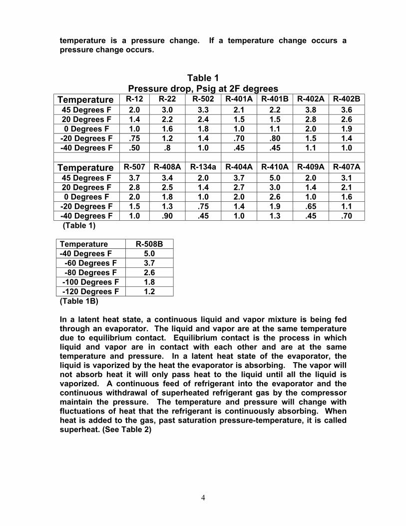
temperature is a pressure change. If a temperature change occurs a pressure change occurs.
Table 1 Pressure drop, Psig at 2F degrees
Temperature R-12 R-22 R-502 R-401A R-401B R-402A R-402B 45 Degrees F 2.0 3.0 3.3 2.1 2.2 3.8 3.6 20 Degrees F 1.4 2.2 2.4 1.5 1.5 2.8 2.6 0 Degrees F 1.0 1.6 1.8 1.0 1.1 2.0 1.9
-20 Degrees F .75 1.2 1.4 .70 .80 1.5 1.4 -40 Degrees F .50 .8 1.0 .45 .45 1.1 1.0
Temperature R-507 R-408A R-134a R-404A R-410A R-409A R-407A
45 Degrees F 3.7 3.4 2.0 3.7 5.0 2.0 3.1 20 Degrees F 2.8 2.5 1.4 2.7 3.0 1.4 2.1 0 Degrees F 2.0 1.8 1.0 2.0 2.6 1.0 1.6
-20 Degrees F 1.5 1.3 .75 1.4 1.9 .65 1.1 -40 Degrees F 1.0 .90 .45 1.0 1.3 .45 .70 (Table 1)
Temperature R-508B -40 Degrees F 5.0
-60 Degrees F 3.7 -80 Degrees F 2.6
-100 Degrees F 1.8 -120 Degrees F 1.2
(Table 1B)
In a latent heat state, a continuous liquid and vapor mixture is being fed through an evaporator. The liquid and vapor are at the same temperature due to equilibrium contact. Equilibrium contact is the process in which liquid and vapor are in contact with each other and are at the same temperature and pressure. In a latent heat state of the evaporator, the liquid is vaporized by the heat the evaporator is absorbing. The vapor will not absorb heat it will only pass heat to the liquid until all the liquid is vaporized. A continuous feed of refrigerant into the evaporator and the continuous withdrawal of superheated refrigerant gas by the compressor maintain the pressure. The temperature and pressure will change with fluctuations of heat that the refrigerant is continuously absorbing. When heat is added to the gas, past saturation pressure-temperature, it is called superheat. (See Table 2)
4
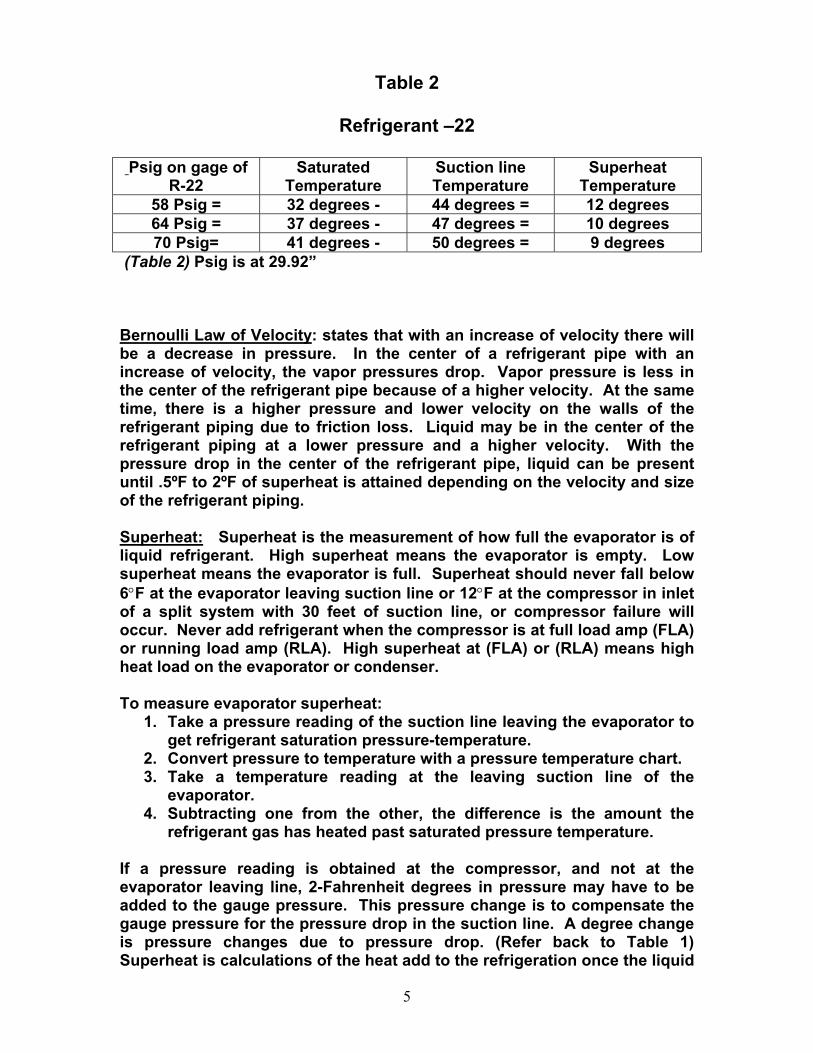
Table 2
Refrigerant –22
Psig on gage of R-22
Saturated Temperature
Suction line Temperature
Superheat Temperature
58 Psig = 32 degrees - 44 degrees = 12 degrees 64 Psig = 37 degrees - 47 degrees = 10 degrees 70 Psig= 41 degrees - 50 degrees = 9 degrees
(Table 2) Psig is at 29.92”
Bernoulli Law of Velocity: states that with an increase of velocity there will be a decrease in pressure. In the center of a refrigerant pipe with an increase of velocity, the vapor pressures drop. Vapor pressure is less in the center of the refrigerant pipe because of a higher velocity. At the same time, there is a higher pressure and lower velocity on the walls of the refrigerant piping due to friction loss. Liquid may be in the center of the refrigerant piping at a lower pressure and a higher velocity. With the pressure drop in the center of the refrigerant pipe, liquid can be present until .5ºF to 2ºF of superheat is attained depending on the velocity and size of the refrigerant piping. Superheat: Superheat is the measurement of how full the evaporator is of liquid refrigerant. High superheat means the evaporator is empty. Low superheat means the evaporator is full. Superheat should never fall below 6°F at the evaporator leaving suction line or 12°F at the compressor in inlet of a split system with 30 feet of suction line, or compressor failure will occur. Never add refrigerant when the compressor is at full load amp (FLA) or running load amp (RLA). High superheat at (FLA) or (RLA) means high heat load on the evaporator or condenser. To measure evaporator superheat:
1. Take a pressure reading of the suction line leaving the evaporator to get refrigerant saturation pressure-temperature.
2. Convert pressure to temperature with a pressure temperature chart. 3. Take a temperature reading at the leaving suction line of the
evaporator. 4. Subtracting one from the other, the difference is the amount the
refrigerant gas has heated past saturated pressure temperature.
If a pressure reading is obtained at the compressor, and not at the evaporator leaving line, 2-Fahrenheit degrees in pressure may have to be added to the gauge pressure. This pressure change is to compensate the gauge pressure for the pressure drop in the suction line. A degree change is pressure changes due to pressure drop. (Refer back to Table 1) Superheat is calculations of the heat add to the refrigeration once the liquid
5
has vaporized. All pressure drops in a system suction line must be in the calculation of superheat.
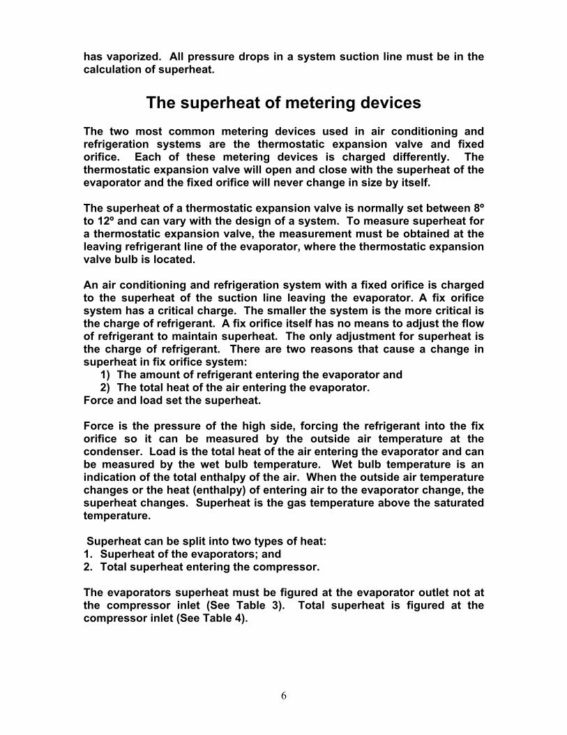
The superheat of metering devices
The two most common metering devices used in air conditioning and refrigeration systems are the thermostatic expansion valve and fixed orifice. Each of these metering devices is charged differently. The thermostatic expansion valve will open and close with the superheat of the evaporator and the fixed orifice will never change in size by itself. The superheat of a thermostatic expansion valve is normally set between 8º to 12º and can vary with the design of a system. To measure superheat for a thermostatic expansion valve, the measurement must be obtained at the leaving refrigerant line of the evaporator, where the thermostatic expansion valve bulb is located. An air conditioning and refrigeration system with a fixed orifice is charged to the superheat of the suction line leaving the evaporator. A fix orifice system has a critical charge. The smaller the system is the more critical is the charge of refrigerant. A fix orifice itself has no means to adjust the flow of refrigerant to maintain superheat. The only adjustment for superheat is the charge of refrigerant. There are two reasons that cause a change in superheat in fix orifice system:
1) The amount of refrigerant entering the evaporator and 2) The total heat of the air entering the evaporator.
Force and load set the superheat. Force is the pressure of the high side, forcing the refrigerant into the fix orifice so it can be measured by the outside air temperature at the condenser. Load is the total heat of the air entering the evaporator and can be measured by the wet bulb temperature. Wet bulb temperature is an indication of the total enthalpy of the air. When the outside air temperature changes or the heat (enthalpy) of entering air to the evaporator change, the superheat changes. Superheat is the gas temperature above the saturated temperature. Superheat can be split into two types of heat: 1. Superheat of the evaporators; and 2. Total superheat entering the compressor. The evaporators superheat must be figured at the evaporator outlet not at the compressor inlet (See Table 3). Total superheat is figured at the compressor inlet (See Table 4).
6
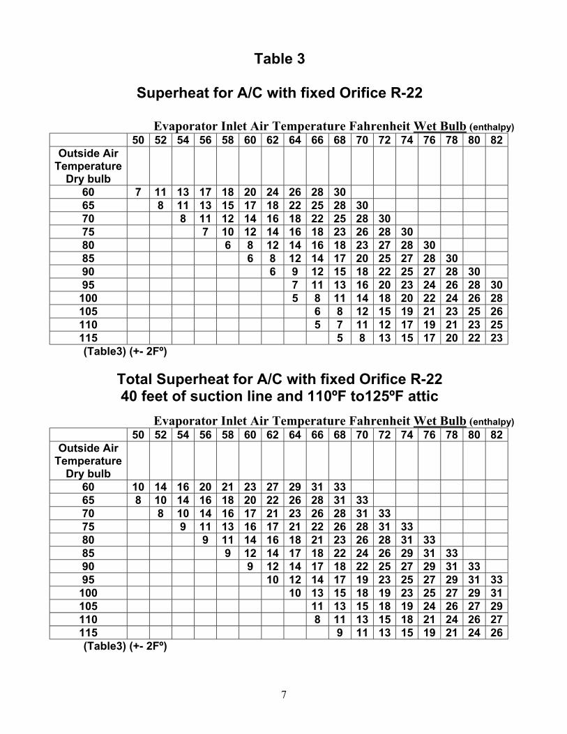
Table 3
Superheat for A/C with fixed Orifice R-22
Evaporator Inlet Air Temperature Fahrenheit Wet Bulb (enthalpy) 50 52 54 56 58 60 62 64 66 68 70 72 74 76 78 80 82
Outside Air Temperature
Dry bulb
60 7 11 13 17 18 20 24 26 28 30 65 8 11 13 15 17 18 22 25 28 30 70 8 11 12 14 16 18 22 25 28 30 75 7 10 12 14 16 18 23 26 28 30 80 6 8 12 14 16 18 23 27 28 30 85 6 8 12 14 17 20 25 27 28 30 90 6 9 12 15 18 22 25 27 28 30 95 7 11 13 16 20 23 24 26 28 30
100 5 8 11 14 18 20 22 24 26 28 105 6 8 12 15 19 21 23 25 26 110 5 7 11 12 17 19 21 23 25 115 5 8 13 15 17 20 22 23 (Table3) (+- 2Fº)
Total Superheat for A/C with fixed Orifice R-22 40 feet of suction line and 110ºF to125ºF attic
Evaporator Inlet Air Temperature Fahrenheit Wet Bulb (enthalpy) 50 52 54 56 58 60 62 64 66 68 70 72 74 76 78 80 82
Outside Air Temperature
Dry bulb
60 10 14 16 20 21 23 27 29 31 33 65 8 10 14 16 18 20 22 26 28 31 33 70 8 10 14 16 17 21 23 26 28 31 33 75 9 11 13 16 17 21 22 26 28 31 33 80 9 11 14 16 18 21 23 26 28 31 33 85 9 12 14 17 18 22 24 26 29 31 33 90 9 12 14 17 18 22 25 27 29 31 33 95 10 12 14 17 19 23 25 27 29 31 33
100 10 13 15 18 19 23 25 27 29 31 105 11 13 15 18 19 24 26 27 29 110 8 11 13 15 18 21 24 26 27 115 9 11 13 15 19 21 24 26 (Table3) (+- 2Fº)
7
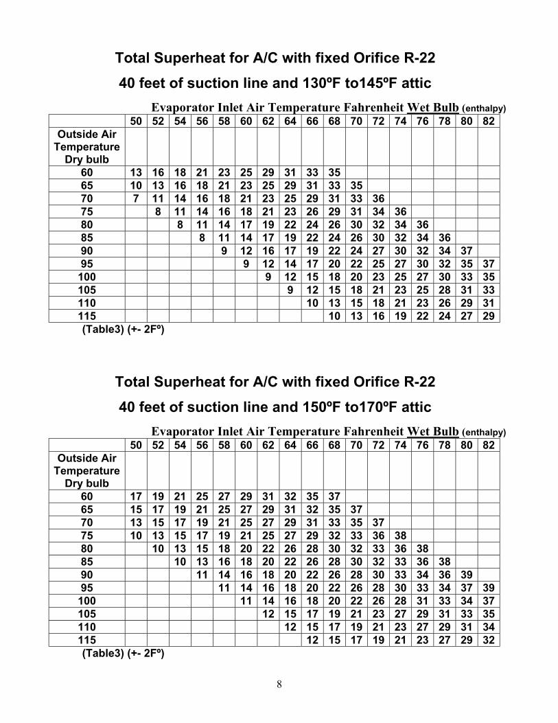
Total Superheat for A/C with fixed Orifice R-22 40 feet of suction line and 130ºF to145ºF attic
Evaporator Inlet Air Temperature Fahrenheit Wet Bulb (enthalpy) 50 52 54 56 58 60 62 64 66 68 70 72 74 76 78 80 82
Outside Air Temperature
Dry bulb
60 13 16 18 21 23 25 29 31 33 35 65 10 13 16 18 21 23 25 29 31 33 35 70 7 11 14 16 18 21 23 25 29 31 33 36 75 8 11 14 16 18 21 23 26 29 31 34 36 80 8 11 14 17 19 22 24 26 30 32 34 36 85 8 11 14 17 19 22 24 26 30 32 34 36 90 9 12 16 17 19 22 24 27 30 32 34 37 95 9 12 14 17 20 22 25 27 30 32 35 37
100 9 12 15 18 20 23 25 27 30 33 35 105 9 12 15 18 21 23 25 28 31 33 110 10 13 15 18 21 23 26 29 31 115 10 13 16 19 22 24 27 29 (Table3) (+- 2Fº)
Total Superheat for A/C with fixed Orifice R-22 40 feet of suction line and 150ºF to170ºF attic
Evaporator Inlet Air Temperature Fahrenheit Wet Bulb (enthalpy) 50 52 54 56 58 60 62 64 66 68 70 72 74 76 78 80 82
Outside Air Temperature
Dry bulb
60 17 19 21 25 27 29 31 32 35 37 65 15 17 19 21 25 27 29 31 32 35 37 70 13 15 17 19 21 25 27 29 31 33 35 37 75 10 13 15 17 19 21 25 27 29 32 33 36 38 80 10 13 15 18 20 22 26 28 30 32 33 36 38 85 10 13 16 18 20 22 26 28 30 32 33 36 38 90 11 14 16 18 20 22 26 28 30 33 34 36 39 95 11 14 16 18 20 22 26 28 30 33 34 37 39
100 11 14 16 18 20 22 26 28 31 33 34 37 105 12 15 17 19 21 23 27 29 31 33 35 110 12 15 17 19 21 23 27 29 31 34 115 12 15 17 19 21 23 27 29 32 (Table3) (+- 2Fº)
8
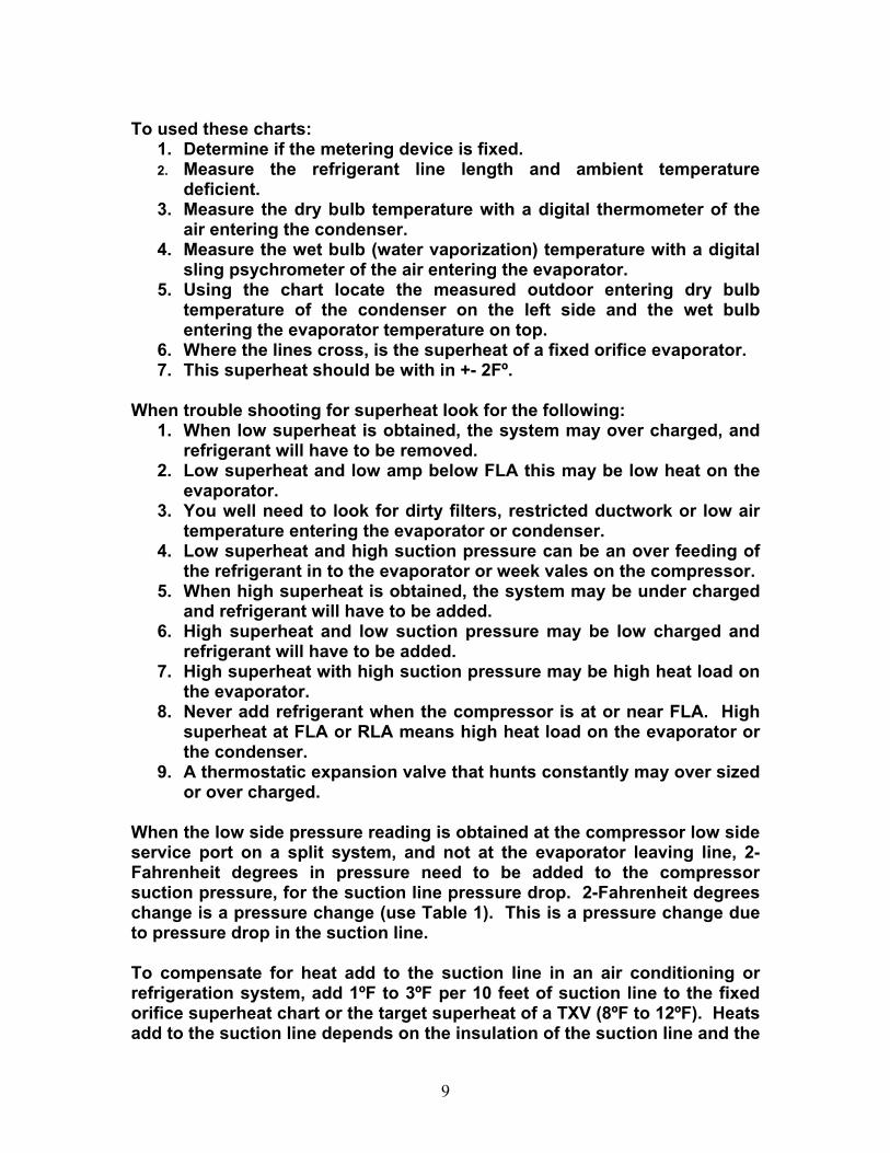
To used these charts: 1. Determine if the metering device is fixed. 2. Measure the refrigerant line length and ambient temperature
deficient. 3. Measure the dry bulb temperature with a digital thermometer of the
air entering the condenser. 4. Measure the wet bulb (water vaporization) temperature with a digital
sling psychrometer of the air entering the evaporator. 5. Using the chart locate the measured outdoor entering dry bulb
temperature of the condenser on the left side and the wet bulb entering the evaporator temperature on top.
6. Where the lines cross, is the superheat of a fixed orifice evaporator. 7. This superheat should be with in +- 2Fº.
When trouble shooting for superheat look for the following:
1. When low superheat is obtained, the system may over charged, and refrigerant will have to be removed.
2. Low superheat and low amp below FLA this may be low heat on the evaporator.
3. You well need to look for dirty filters, restricted ductwork or low air temperature entering the evaporator or condenser.
4. Low superheat and high suction pressure can be an over feeding of the refrigerant in to the evaporator or week vales on the compressor.
5. When high superheat is obtained, the system may be under charged and refrigerant will have to be added.
6. High superheat and low suction pressure may be low charged and refrigerant will have to be added.
7. High superheat with high suction pressure may be high heat load on the evaporator.
8. Never add refrigerant when the compressor is at or near FLA. High superheat at FLA or RLA means high heat load on the evaporator or the condenser.
9. A thermostatic expansion valve that hunts constantly may over sized or over charged.
When the low side pressure reading is obtained at the compressor low side service port on a split system, and not at the evaporator leaving line, 2-Fahrenheit degrees in pressure need to be added to the compressor suction pressure, for the suction line pressure drop. 2-Fahrenheit degrees change is a pressure change (use Table 1). This is a pressure change due to pressure drop in the suction line. To compensate for heat add to the suction line in an air conditioning or refrigeration system, add 1ºF to 3ºF per 10 feet of suction line to the fixed orifice superheat chart or the target superheat of a TXV (8ºF to 12ºF). Heats add to the suction line depends on the insulation of the suction line and the
9
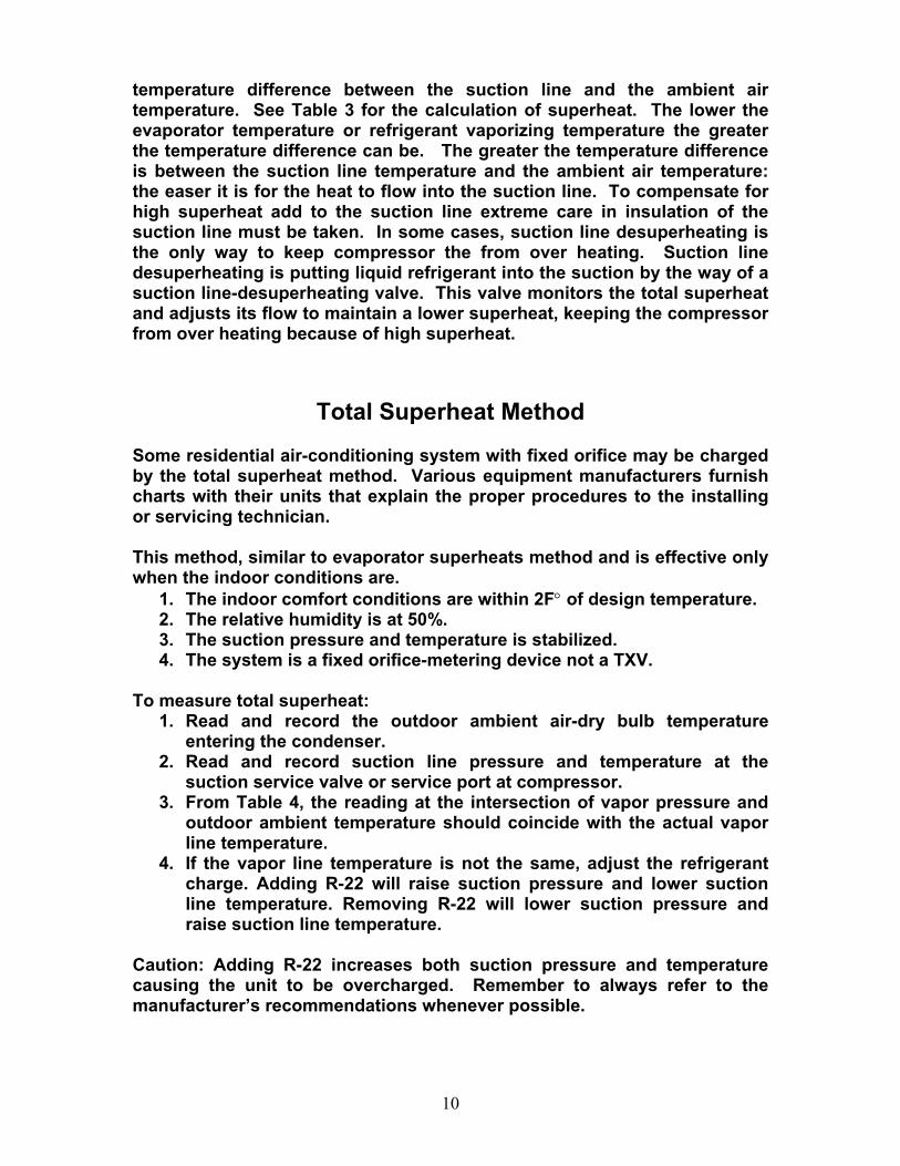
temperature difference between the suction line and the ambient air temperature. See Table 3 for the calculation of superheat. The lower the evaporator temperature or refrigerant vaporizing temperature the greater the temperature difference can be. The greater the temperature difference is between the suction line temperature and the ambient air temperature: the easer it is for the heat to flow into the suction line. To compensate for high superheat add to the suction line extreme care in insulation of the suction line must be taken. In some cases, suction line desuperheating is the only way to keep compressor the from over heating. Suction line desuperheating is putting liquid refrigerant into the suction by the way of a suction line-desuperheating valve. This valve monitors the total superheat and adjusts its flow to maintain a lower superheat, keeping the compressor from over heating because of high superheat.
Total Superheat Method Some residential air-conditioning system with fixed orifice may be charged by the total superheat method. Various equipment manufacturers furnish charts with their units that explain the proper procedures to the installing or servicing technician. This method, similar to evaporator superheats method and is effective only when the indoor conditions are.
1. The indoor comfort conditions are within 2F° of design temperature. 2. The relative humidity is at 50%. 3. The suction pressure and temperature is stabilized. 4. The system is a fixed orifice-metering device not a TXV.
To measure total superheat:
1. Read and record the outdoor ambient air-dry bulb temperature entering the condenser.
2. Read and record suction line pressure and temperature at the suction service valve or service port at compressor.
3. From Table 4, the reading at the intersection of vapor pressure and outdoor ambient temperature should coincide with the actual vapor line temperature.
4. If the vapor line temperature is not the same, adjust the refrigerant charge. Adding R-22 will raise suction pressure and lower suction line temperature. Removing R-22 will lower suction pressure and raise suction line temperature.
Caution: Adding R-22 increases both suction pressure and temperature causing the unit to be overcharged. Remember to always refer to the manufacturer’s recommendations whenever possible.
10
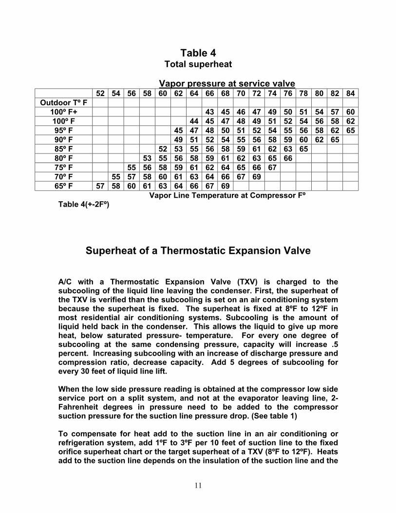
Table 4
Total superheat Vapor pressure at service valve
52 54 56 58 60 62 64 66 68 70 72 74 76 78 80 82 84 Outdoor Tº F
100º F+ 43 45 46 47 49 50 51 54 57 60 100º F 44 45 47 48 49 51 52 54 56 58 62 95º F 45 47 48 50 51 52 54 55 56 58 62 65 90º F 49 51 52 54 55 56 58 59 60 62 65 85º F 52 53 55 56 58 59 61 62 63 65 80º F 53 55 56 58 59 61 62 63 65 66 75º F 55 56 58 59 61 62 64 65 66 67 70º F 55 57 58 60 61 63 64 66 67 69 65º F 57 58 60 61 63 64 66 67 69
Vapor Line Temperature at Compressor Fº Table 4(+-2Fº)
Superheat of a Thermostatic Expansion Valve
A/C with a Thermostatic Expansion Valve (TXV) is charged to the subcooling of the liquid line leaving the condenser. First, the superheat of the TXV is verified than the subcooling is set on an air conditioning system because the superheat is fixed. The superheat is fixed at 8ºF to 12ºF in most residential air conditioning systems. Subcooling is the amount of liquid held back in the condenser. This allows the liquid to give up more heat, below saturated pressure- temperature. For every one degree of subcooling at the same condensing pressure, capacity will increase .5 percent. Increasing subcooling with an increase of discharge pressure and compression ratio, decrease capacity. Add 5 degrees of subcooling for every 30 feet of liquid line lift. When the low side pressure reading is obtained at the compressor low side service port on a split system, and not at the evaporator leaving line, 2-Fahrenheit degrees in pressure need to be added to the compressor suction pressure for the suction line pressure drop. (See table 1) To compensate for heat add to the suction line in an air conditioning or refrigeration system, add 1ºF to 3ºF per 10 feet of suction line to the fixed orifice superheat chart or the target superheat of a TXV (8ºF to 12ºF). Heats add to the suction line depends on the insulation of the suction line and the
11
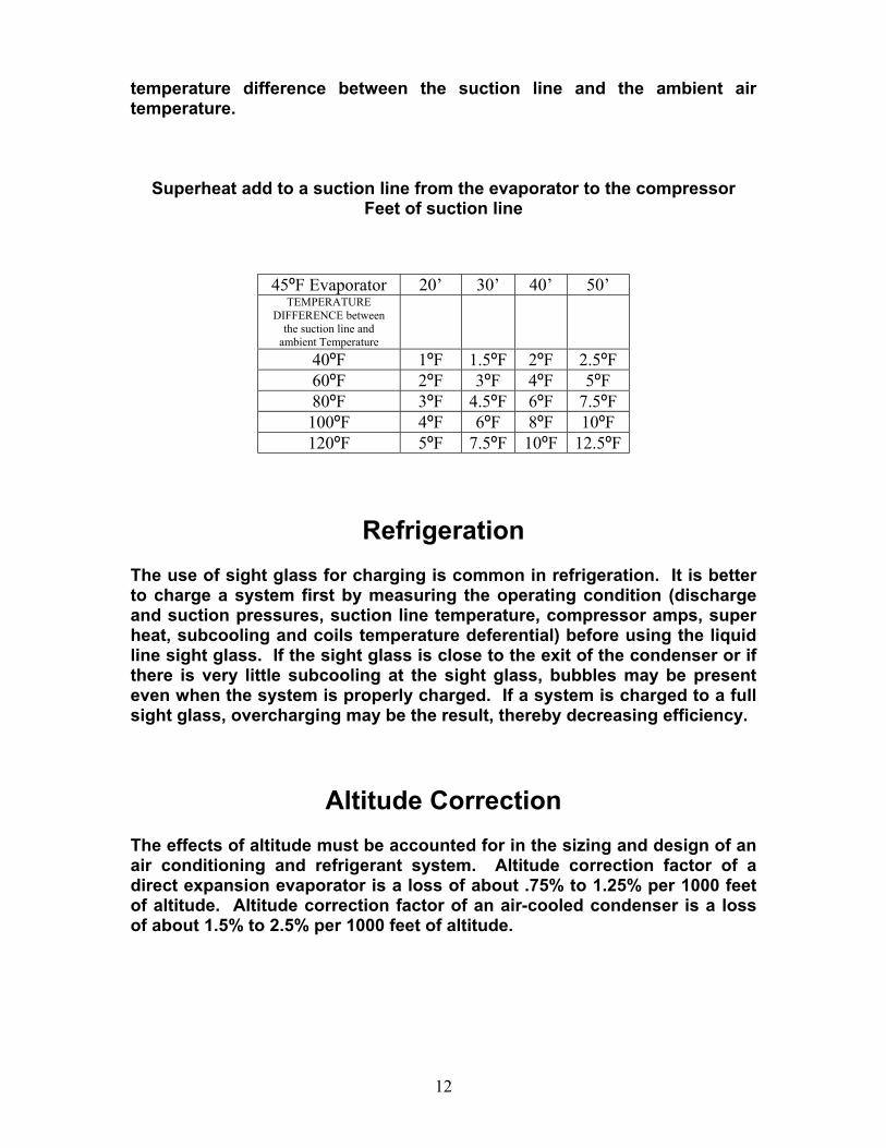
temperature difference between the suction line and the ambient air temperature.
Superheat add to a suction line from the evaporator to the compressor Feet of suction line
45ºF Evaporator 20’ 30’ 40’ 50’ TEMPERATURE
DIFFERENCE between the suction line and
ambient Temperature
40ºF 1ºF 1.5ºF 2ºF 2.5ºF 60ºF 2ºF 3ºF 4ºF 5ºF 80ºF 3ºF 4.5ºF 6ºF 7.5ºF 100ºF 4ºF 6ºF 8ºF 10ºF 120ºF 5ºF 7.5ºF 10ºF 12.5ºF
Refrigeration
The use of sight glass for charging is common in refrigeration. It is better to charge a system first by measuring the operating condition (discharge and suction pressures, suction line temperature, compressor amps, super heat, subcooling and coils temperature deferential) before using the liquid line sight glass. If the sight glass is close to the exit of the condenser or if there is very little subcooling at the sight glass, bubbles may be present even when the system is properly charged. If a system is charged to a full sight glass, overcharging may be the result, thereby decreasing efficiency.
Altitude Correction The effects of altitude must be accounted for in the sizing and design of an air conditioning and refrigerant system. Altitude correction factor of a direct expansion evaporator is a loss of about .75% to 1.25% per 1000 feet of altitude. Altitude correction factor of an air-cooled condenser is a loss of about 1.5% to 2.5% per 1000 feet of altitude.
12

Temperature Difference in A/C Temperature difference of an evaporator coil will vary with the total heat of the air entering the evaporator and the load on the condenser. This temperature will vary from 10º F to 30º F depending on total heat of the air entering the evaporator. The temperature of air decreases progressively as the air passes through an evaporator coil. The drop in air temperature is greatest across the first row of the coil and diminishes as the air passes across each succeeding row. The fact that the temperature difference between the air and the refrigerant is greatest across the first row, and becomes less and less as the temperature of the air is reduced in passing across each succeeding row. The temperature difference is least across the last row of the coil. External factors effect coil performance. Principal among these are the circulation, velocity, and distribution of air in the refrigerated space and over the coil. These factors are closely related and in many cases is dependent one on the other. Heat from the product or condition space is carried to the evaporator by air circulation. When air circulation is inadequate, heat is not carried from the product or condition space to the evaporator at a rate sufficient to allow the evaporator to perform at peak efficiency or capacity. It is important also that the circulation of air is evenly distributed in all parts of the refrigerated space and over the coil. Poor distribution of the air circulating can result in uneven temperatures and dead spots in the air condition space. Uneven distribution of air over the coil surface causes some parts of the surface to function less efficiently than other and lowers evaporator capacity and efficiency. When air velocity is low, the air passing over the coil stays in contact with the coil surface longer. More heat is removed and is cooled with a greater range. Thus, the temperature difference increases, the refrigerant temperature decreases, resulting in a loss of capacity and efficiency because the rate of heat transfer is lowered. As air velocity increases, a greater quantity of air is brought into contact with the evaporator coil. Consequently, the temperature difference decreases, the refrigerant temperature increases, resulting in a gain of capacity and efficiency because the rate of heat transfer is increases. Air volume change across the coil will increase or decrease the refrigerant temperature that increases or decreases the efficiency and capacity of a system. Increasing the heat by increasing the airflow or increasing the evaporating coil size by 10% will be decrease of water removed from the air
13
by 2% to 4%, but there will be a 4% to 8% capacity increase. This will result in a change of the load in the system from a 72% to 74% sensible heat increase and from a 28% to 26% latent heat decrease. An increase of the refrigerant temperature of 1ºF will increase compressor efficiency by 1% to 2%. The reason for the increase in heat and the increase in refrigeration temperature is due to the increasing size and/or airflow of the overall coil. Over size an evaporating coil or increase airflow, decreases the water removing capacity of a coil. Decrease heat by a decrease of airflow or an evaporating coil size by 10% will result in a 2% to 4% increase of water removed from the air, will cause a 4% to 8% capacity decrease. The capacity decrease results in a 72% to 70% decrease of sensible heat change to the load in the system, thereby causing a 28% to 30% latent heat increases. A decrease of the refrigerant temperature of 1ºF will decrease compressor efficiency by 1% to 2%. The decrease compression efficiency is caused by the decrease in heat, and the refrigeration temperature that is due to the decreasing size and/or airflow of the overall coil. Under sizing an evaporating coil or a decrease of refrigerant temperature, increases the water removing capacity of a coil. Lowering the refrigeration below the airs dew point in an existing evaporator coil to remove more water from the air or to increase water-removing capacity. This can be done by lowing the airflow or downsizing the coil but not increasing the coil size. The coolest refrigerant temperature is 34 degrees (no ice on the coil). It is possible to check the airflow of an evaporator coil by knowing the air entering dry bulb and well bulb temperature. (See Table 5) This chart is from an air condition system that is design at 400 CFM per ton, which will remove 6.667 enthalpy (BTU) per pound of air, and is 72% sensible 28% latent load.
14
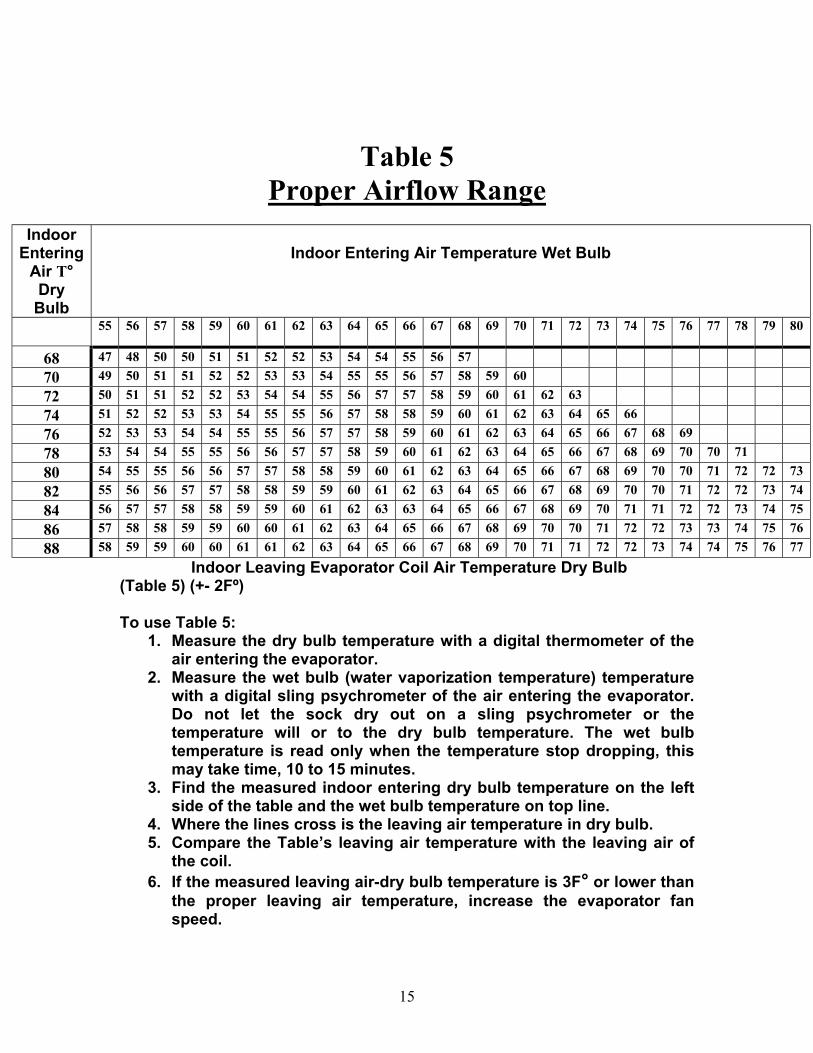
Table 5 Proper Airflow Range
Indoor
Entering Air T° Dry
Bulb
Indoor Entering Air Temperature Wet Bulb
55 56 57 58 59 60 61 62 63 64 65 66 67 68 69 70 71 72 73 74 75 76 77 78 79 80
68 47 48 50 50 51 51 52 52 53 54 54 55 56 57 70 49 50 51 51 52 52 53 53 54 55 55 56 57 58 59 60 72 50 51 51 52 52 53 54 54 55 56 57 57 58 59 60 61 62 63 74 51 52 52 53 53 54 55 55 56 57 58 58 59 60 61 62 63 64 65 66 76 52 53 53 54 54 55 55 56 57 57 58 59 60 61 62 63 64 65 66 67 68 69 78 53 54 54 55 55 56 56 57 57 58 59 60 61 62 63 64 65 66 67 68 69 70 70 71 80 54 55 55 56 56 57 57 58 58 59 60 61 62 63 64 65 66 67 68 69 70 70 71 72 72 73 82 55 56 56 57 57 58 58 59 59 60 61 62 63 64 65 66 67 68 69 70 70 71 72 72 73 74 84 56 57 57 58 58 59 59 60 61 62 63 63 64 65 66 67 68 69 70 71 71 72 72 73 74 75 86 57 58 58 59 59 60 60 61 62 63 64 65 66 67 68 69 70 70 71 72 72 73 73 74 75 76 88 58 59 59 60 60 61 61 62 63 64 65 66 67 68 69 70 71 71 72 72 73 74 74 75 76 77
Indoor Leaving Evaporator Coil Air Temperature Dry Bulb (Table 5) (+- 2Fº)
To use Table 5: 1. Measure the dry bulb temperature with a digital thermometer of the
air entering the evaporator. 2. Measure the wet bulb (water vaporization temperature) temperature
with a digital sling psychrometer of the air entering the evaporator. Do not let the sock dry out on a sling psychrometer or the temperature will or to the dry bulb temperature. The wet bulb temperature is read only when the temperature stop dropping, this may take time, 10 to 15 minutes.
3. Find the measured indoor entering dry bulb temperature on the left side of the table and the wet bulb temperature on top line.
4. Where the lines cross is the leaving air temperature in dry bulb. 5. Compare the Table’s leaving air temperature with the leaving air of
the coil. 6. If the measured leaving air-dry bulb temperature is 3F° or lower than
the proper leaving air temperature, increase the evaporator fan speed.
15
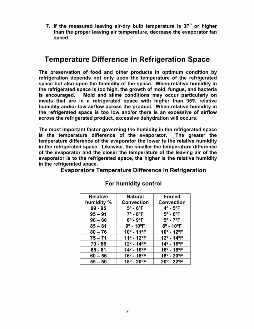
7. If the measured leaving air-dry bulb temperature is 3F° or higher than the proper leaving air temperature, decrease the evaporator fan speed.
Temperature Difference in Refrigeration Space The preservation of food and other products in optimum condition by refrigeration depends not only upon the temperature of the refrigerated space but also upon the humidity of the space. When relative humidity in the refrigerated space is too high, the growth of mold, fungus, and bacteria is encouraged. Mold and slime conditions may occur particularly on meats that are in a refrigerated space with higher than 95% relative humidity and/or low airflow across the product. When relative humidity in the refrigerated space is too low and/or there is an excessive of airflow across the refrigerated product, excessive dehydration will occurs. The most important factor governing the humidity in the refrigerated space is the temperature difference of the evaporator. The greater the temperature difference of the evaporator the lower is the relative humidity in the refrigerated space. Likewise, the smaller the temperature difference of the evaporator and the closer the temperature of the leaving air of the evaporator is to the refrigerated space, the higher is the relative humidity in the refrigerated space.
Evaporators Temperature Difference in Refrigeration
For humidity control
Relative humidity %
Natural Convection
Forced Convection
99 - 95 5º - 6ºF 4º - 5ºF 95 – 91 7º - 8ºF 5º - 6ºF 90 – 86 8º - 9ºF 5º - 7ºF 85 – 81 9º - 10ºF 8º - 10ºF 80 – 76 10º - 11ºF 10º - 12ºF 75 – 71 11º - 12ºF 12º - 14ºF 70 - 66 12º - 14ºF 14º - 16ºF 65 - 61 14º - 16ºF 16º - 18ºF 60 – 56 16º - 18ºF 18º - 20ºF 55 – 50 18º - 20ºF 20º - 22ºF
16
For temperature and relative humidity for refrigerated product
spaces see ASHRAE 2002 Refrigeration Handbook (Chapter 10) Commodity Storage Requirements
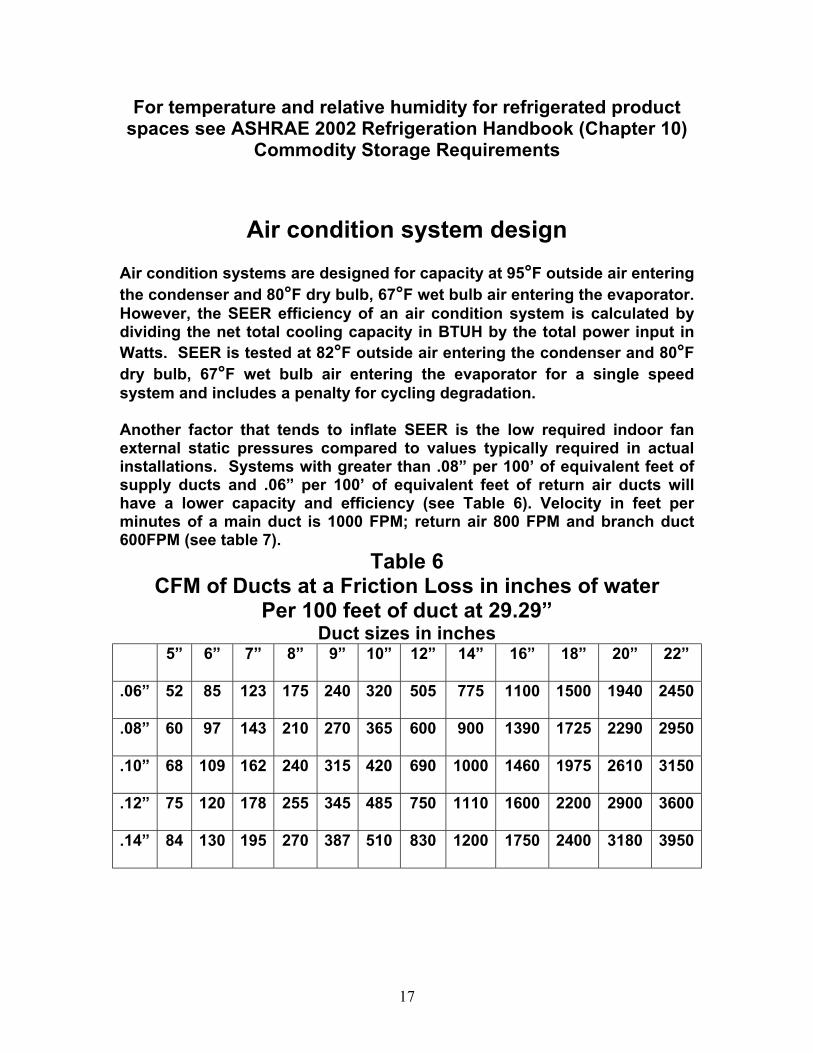
Air condition system design Air condition systems are designed for capacity at 95°F outside air entering the condenser and 80°F dry bulb, 67°F wet bulb air entering the evaporator. However, the SEER efficiency of an air condition system is calculated by dividing the net total cooling capacity in BTUH by the total power input in Watts. SEER is tested at 82°F outside air entering the condenser and 80°F dry bulb, 67°F wet bulb air entering the evaporator for a single speed system and includes a penalty for cycling degradation. Another factor that tends to inflate SEER is the low required indoor fan external static pressures compared to values typically required in actual installations. Systems with greater than .08” per 100’ of equivalent feet of supply ducts and .06” per 100’ of equivalent feet of return air ducts will have a lower capacity and efficiency (see Table 6). Velocity in feet per minutes of a main duct is 1000 FPM; return air 800 FPM and branch duct 600FPM (see table 7).
Table 6 CFM of Ducts at a Friction Loss in inches of water
Per 100 feet of duct at 29.29” Duct sizes in inches
5” 6” 7” 8” 9” 10” 12” 14” 16” 18” 20” 22”
.06” 52 85 123 175 240 320 505 775 1100 1500 1940 2450
.08” 60 97 143 210 270 365 600 900 1390 1725 2290 2950
.10” 68 109 162 240 315 420 690 1000 1460 1975 2610 3150
.12” 75 120 178 255 345 485 750 1110 1600 2200 2900 3600
.14” 84 130 195 270 387 510 830 1200 1750 2400 3180 3950
17
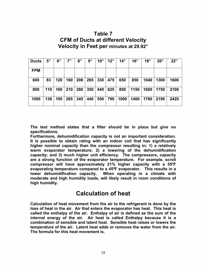
Table 7 CFM of Ducts at different Velocity
Velocity in Feet per minutes at 29.92”
Ducts 5” 6” 7” 8” 9” 10” 12” 14” 16” 18” 20” 22”
FPM
600 83 120 160 208 265 330 475 650 850 1040 1300 1600
800 110 160 210 280 350 440 625 850 1150 1600 1750 2100
1000 138 195 265 345 440 550 790 1090 1400 1780 2190 2420
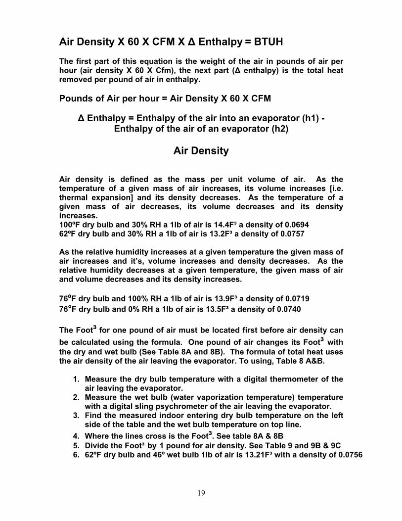
The test method states that a filter should be in place but give no specifications. Furthermore, dehumidification capacity is not an important consideration. It is possible to obtain rating with an indoor coil that has significantly higher nominal capacity than the compressor resulting in: 1) a relatively warm evaporator temperature; 2) a lowering of the dehumidification capacity; and 3) much higher unit efficiency. The compressors, capacity are a strong function of the evaporator temperature. For example, scroll compressor will have approximately 21% higher capacity with a 55ºF evaporating temperature compared to a 45ºF evaporator. This results in a lower dehumidification capacity. When operating in a climate with moderate and high humidity loads, will likely result in room conditions of high humidity.
Calculation of heat Calculation of heat movement from the air to the refrigerant is done by the loss of heat in the air. Air that enters the evaporator has heat. This heat is called the enthalpy of the air. Enthalpy of air is defined as the sum of the internal energy of the air. Air heat is called Enthalpy because it is a combination of sensible and latent heat. Sensible heat raises or lowers the temperature of the air. Latent heat adds or removes the water from the air. The formula for this heat movement is.
18
Air Density X 60 X CFM X ∆ Enthalpy = BTUH The first part of this equation is the weight of the air in pounds of air per hour (air density X 60 X Cfm), the next part (∆ enthalpy) is the total heat removed per pound of air in enthalpy. Pounds of Air per hour = Air Density X 60 X CFM
∆ Enthalpy = Enthalpy of the air into an evaporator (h1) -
Enthalpy of the air of an evaporator (h2)
Air Density Air density is defined as the mass per unit volume of air. As the temperature of a given mass of air increases, its volume increases [i.e. thermal expansion] and its density decreases. As the temperature of a given mass of air decreases, its volume decreases and its density increases. 100ºF dry bulb and 30% RH a 1lb of air is 14.4F³ a density of 0.0694 62ºF dry bulb and 30% RH a 1lb of air is 13.2F³ a density of 0.0757 As the relative humidity increases at a given temperature the given mass of air increases and it’s, volume increases and density decreases. As the relative humidity decreases at a given temperature, the given mass of air and volume decreases and its density increases. 76ºF dry bulb and 100% RH a 1lb of air is 13.9F³ a density of 0.0719 76°F dry bulb and 0% RH a 1lb of air is 13.5F³ a density of 0.0740 The Foot³ for one pound of air must be located first before air density can be calculated using the formula. One pound of air changes its Foot³ with the dry and wet bulb (See Table 8A and 8B). The formula of total heat uses the air density of the air leaving the evaporator. To using, Table 8 A&B.
1. Measure the dry bulb temperature with a digital thermometer of the air leaving the evaporator.
2. Measure the wet bulb (water vaporization temperature) temperature with a digital sling psychrometer of the air leaving the evaporator.
3. Find the measured indoor entering dry bulb temperature on the left side of the table and the wet bulb temperature on top line.
4. Where the lines cross is the Foot³. See table 8A & 8B 5. Divide the Foot³ by 1 pound for air density. See Table 9 and 9B & 9C 6. 62ºF dry bulb and 46º wet bulb 1lb of air is 13.21F³ with a density of 0.0756
19

Foot³ of one pound of air Table 8A
Dry Bulb on left, Wet Bulb on top
70 68 66 64 62 60 58 56 54 52 50 48 46 44 70 13.69 13.65 13.62 13.59 13.56 13.54 13.51 13.49 13.46 13.44 13.42 13.39 13.37 13.35 69 13.63 13.60 13.57 13.54 13.52 13.49 13.44 13.42 13.39 13.37 13.35 13.33 68 13.61 13.58 13.55
13.46 13.52 13.49 13.67 13.44 13.42 13.39 13.37 13.35 13.33 13.31
67 13.56 13.53 13.50 13.47 13.45 13.42 13.40 13.78 13.35 13.33 13.31 13.29 66 13.54 13.51 13.48 13.45 13.43 13.40 13.38 13.36 13.31 13.29 13.27 65 13.49 13.46 13.43 13.41 13.38 13.36 13.33 13.31 13.27 13.25 64 13.47 13.44 13.41 13.39 13.36 13.34 13.31 13.29 13.27 13.23 63 13.42 13.39 13.37 13.34 13.32 13.29 13.27 13.25 13.23
13.33 13.29
13.25 13.21
62 13.40 13.37 13.35 13.32 13.30 13.27 13.25 13.23 13.21 13.19 61 13.35 13.32 13.30 13.28 13.25 13.23 13.21 13.19 13.17 60 13.33 13.30 13.28 13.25 13.23 13.21 13.19 13.17 13.15
Foot³ of one pound of air at 29.92”
Table 8B Dry Bulb on left, Wet Bulb on top
60 58 56 54 52 50 48 46 44 42 40 38 36 34 65 13.43 13.40 13.38 13.35 13.33 13.31 13.29 13.27 13.25 13.23 64 13.41 13.38 13.36 13.33 13.31 13.29 13.27 13.25 13.23 13.21 63 13.39 13.36 13.34 13.31 13.29 13.27 13.25 13.23 13.21 13.19 13.17 62 13.37 13.34 13.32 13.29 13.27 13.25 13.22 13.21 13.19 13.17 13.15 61 13.35 13.32 13.29 13.27 13.25 13.23 13.21 13.19 13.17 13.15 13.13 60 13.33 13.30 13.27 13.25 13.23 13.21 13.19 13.17 13.15 13.13 13.11 59 13.28 13.25 13.23 13.21 13.19 13.17 13.15 13.13 13.11 13.09 13.08 58 13.26 13.23 13.21 13.19 13.17 13.15 13.13 13.11 13.09 13.07 13.05 57 13.21 13.19 13.17 13.15 13.13 13.11 13.09 13.07 13.05 13.03 56 13.19 13.17 13.15 13.13 13.11 13.8 13.07 13.05 13.03 13.01 55 13.15 13.13 13.11 13.08 13.06 13.04 13.03 13.01 12.99 12.97 54 13.13 13.11 13.08 13.06 13.04 13.03 13.01 12.98 12.97 12.95 53 13.08 13.06 13.04 13.03 13.00 12.98 12.97 12.95 12.93 52 13.06 13.04 13.03 13.00 12.98 12.96 12.95 12.93 12.91 12.89 51 13.02 13.00 12.98 12.96 12.95 12.93 12.91 12.89 12.87 50 13.00 12.98 12.96 12.94 12.92 12.91 12.88 12.87 12.85 49 12.96 12.94 12.92 12.90 12.88 12.87 12.85 12.83 48 12.94 12.92 12.90 12.88 12.87 12.85 12.83 12.81 47 12.90 12.88 12.86 12.84 12.83 12.81 12.79 46 12.88 12.86 12.84 12.82 12.80 12.79 12.77 45 12.84 12.82 12.80 12.78 12.77 12.75 44 12.82 12.80 12.78 12.76 12.75 12.73
20
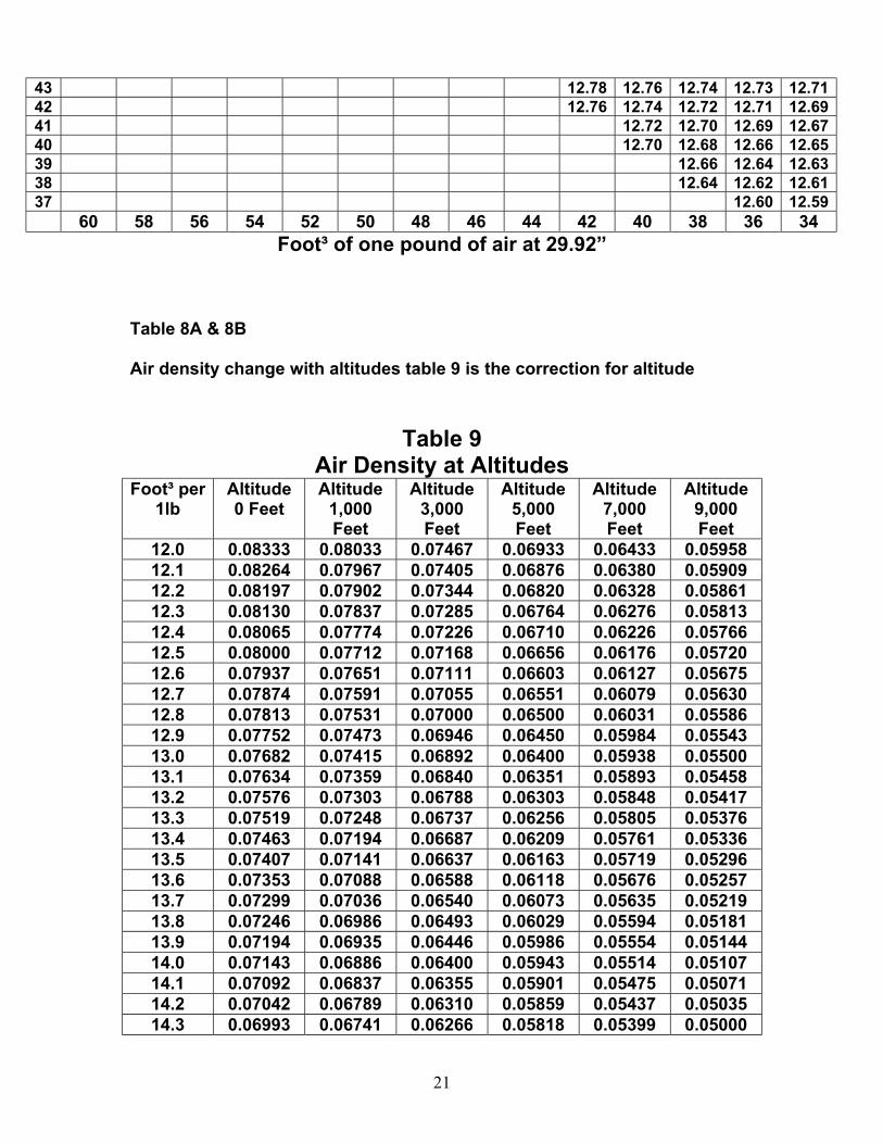
43 12.78 12.76 12.74 12.73 12.71 42 12.76 12.74 12.72 12.71 12.69 41 12.72 12.70 12.69 12.67 40 12.70 12.68 12.66 12.65 39 12.66 12.64 12.63 38 12.64 12.62 12.61 37 12.60 12.59
60 58 56 54 52 50 48 46 44 42 40 38 36 34 Foot³ of one pound of air at 29.92”
Table 8A & 8B
Air density change with altitudes table 9 is the correction for altitude
Table 9
Air Density at Altitudes Foot³ per
1lb Altitude 0 Feet
Altitude 1,000 Feet
Altitude 3,000 Feet
Altitude 5,000 Feet
Altitude 7,000 Feet
Altitude 9,000 Feet
12.0 0.08333 0.08033 0.07467 0.06933 0.06433 0.05958 12.1 0.08264 0.07967 0.07405 0.06876 0.06380 0.05909 12.2 0.08197 0.07902 0.07344 0.06820 0.06328 0.05861 12.3 0.08130 0.07837 0.07285 0.06764 0.06276 0.05813 12.4 0.08065 0.07774 0.07226 0.06710 0.06226 0.05766 12.5 0.08000 0.07712 0.07168 0.06656 0.06176 0.05720 12.6 0.07937 0.07651 0.07111 0.06603 0.06127 0.05675 12.7 0.07874 0.07591 0.07055 0.06551 0.06079 0.05630 12.8 0.07813 0.07531 0.07000 0.06500 0.06031 0.05586 12.9 0.07752 0.07473 0.06946 0.06450 0.05984 0.05543 13.0 0.07682 0.07415 0.06892 0.06400 0.05938 0.05500 13.1 0.07634 0.07359 0.06840 0.06351 0.05893 0.05458 13.2 0.07576 0.07303 0.06788 0.06303 0.05848 0.05417 13.3 0.07519 0.07248 0.06737 0.06256 0.05805 0.05376 13.4 0.07463 0.07194 0.06687 0.06209 0.05761 0.05336 13.5 0.07407 0.07141 0.06637 0.06163 0.05719 0.05296 13.6 0.07353 0.07088 0.06588 0.06118 0.05676 0.05257 13.7 0.07299 0.07036 0.06540 0.06073 0.05635 0.05219 13.8 0.07246 0.06986 0.06493 0.06029 0.05594 0.05181 13.9 0.07194 0.06935 0.06446 0.05986 0.05554 0.05144 14.0 0.07143 0.06886 0.06400 0.05943 0.05514 0.05107 14.1 0.07092 0.06837 0.06355 0.05901 0.05475 0.05071 14.2 0.07042 0.06789 0.06310 0.05859 0.05437 0.05035 14.3 0.06993 0.06741 0.06266 0.05818 0.05399 0.05000
21
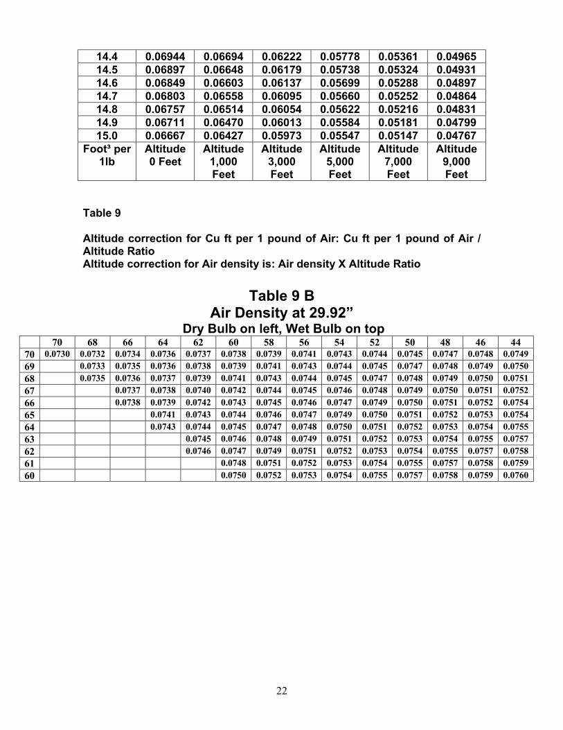
14.4 0.06944 0.06694 0.06222 0.05778 0.05361 0.04965 14.5 0.06897 0.06648 0.06179 0.05738 0.05324 0.04931 14.6 0.06849 0.06603 0.06137 0.05699 0.05288 0.04897 14.7 0.06803 0.06558 0.06095 0.05660 0.05252 0.04864 14.8 0.06757 0.06514 0.06054 0.05622 0.05216 0.04831 14.9 0.06711 0.06470 0.06013 0.05584 0.05181 0.04799 15.0 0.06667 0.06427 0.05973 0.05547 0.05147 0.04767
Foot³ per 1lb
Altitude 0 Feet
Altitude 1,000 Feet
Altitude 3,000 Feet
Altitude 5,000 Feet
Altitude 7,000 Feet
Altitude 9,000 Feet
Table 9
Altitude correction for Cu ft per 1 pound of Air: Cu ft per 1 pound of Air / Altitude Ratio Altitude correction for Air density is: Air density X Altitude Ratio
Table 9 B
Air Density at 29.92” Dry Bulb on left, Wet Bulb on top
70 68 66 64 62 60 58 56 54 52 50 48 46 44 70 0.0730 0.0732 0.0734 0.0736 0.0737 0.0738 0.0739 0.0741 0.0743 0.0744 0.0745 0.0747 0.0748 0.0749 69 0.0733 0.0735 0.0736 0.0738 0.0739 0.0741 0.0743 0.0744 0.0745 0.0747 0.0748 0.0749 0.0750 68 0.0735 0.0736 0.0737 0.0739 0.0741 0.0743 0.0744 0.0745 0.0747 0.0748 0.0749 0.0750 0.0751 67 0.0737 0.0738 0.0740 0.0742 0.0744 0.0745 0.0746 0.0748 0.0749 0.0750 0.0751 0.0752 66 0.0738 0.0739 0.0742 0.0743 0.0745 0.0746 0.0747 0.0749 0.0750 0.0751 0.0752 0.0754 65 0.0741 0.0743 0.0744 0.0746 0.0747 0.0749 0.0750 0.0751 0.0752 0.0753 0.0754 64 0.0743 0.0744 0.0745 0.0747 0.0748 0.0750 0.0751 0.0752 0.0753 0.0754 0.0755 63 0.0745 0.0746 0.0748 0.0749 0.0751 0.0752 0.0753 0.0754 0.0755 0.0757 62 0.0746 0.0747 0.0749 0.0751 0.0752 0.0753 0.0754 0.0755 0.0757 0.0758 61 0.0748 0.0751 0.0752 0.0753 0.0754 0.0755 0.0757 0.0758 0.0759 60 0.0750 0.0752 0.0753 0.0754 0.0755 0.0757 0.0758 0.0759 0.0760
22
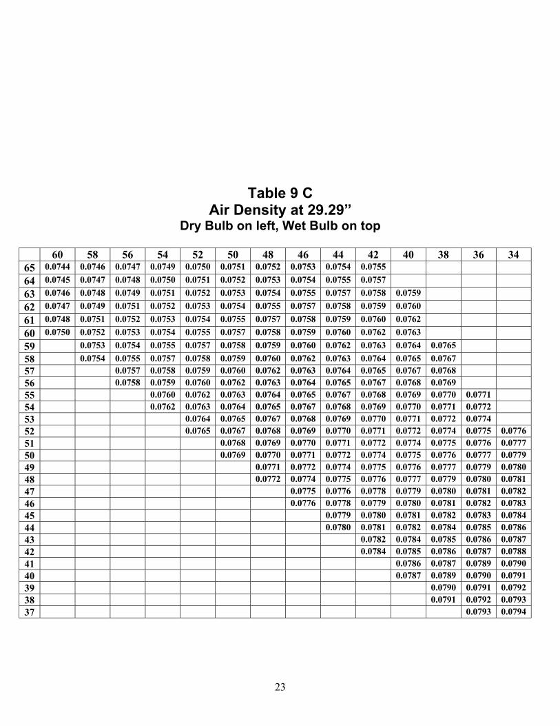
Table 9 C Air Density at 29.29”
Dry Bulb on left, Wet Bulb on top
60 58 56 54 52 50 48 46 44 42 40 38 36 34 65 0.0744 0.0746 0.0747 0.0749 0.0750 0.0751 0.0752 0.0753 0.0754 0.0755 64 0.0745 0.0747 0.0748 0.0750 0.0751 0.0752 0.0753 0.0754 0.0755 0.0757 63 0.0746 0.0748 0.0749 0.0751 0.0752 0.0753 0.0754 0.0755 0.0757 0.0758 0.0759 62 0.0747 0.0749 0.0751 0.0752 0.0753 0.0754 0.0755 0.0757 0.0758 0.0759 0.0760 61 0.0748 0.0751 0.0752 0.0753 0.0754 0.0755 0.0757 0.0758 0.0759 0.0760 0.0762 60 0.0750 0.0752 0.0753 0.0754 0.0755 0.0757 0.0758 0.0759 0.0760 0.0762 0.0763 59 0.0753 0.0754 0.0755 0.0757 0.0758 0.0759 0.0760 0.0762 0.0763 0.0764 0.0765 58 0.0754 0.0755 0.0757 0.0758 0.0759 0.0760 0.0762 0.0763 0.0764 0.0765 0.0767 57 0.0757 0.0758 0.0759 0.0760 0.0762 0.0763 0.0764 0.0765 0.0767 0.0768 56 0.0758 0.0759 0.0760 0.0762 0.0763 0.0764 0.0765 0.0767 0.0768 0.0769 55 0.0760 0.0762 0.0763 0.0764 0.0765 0.0767 0.0768 0.0769 0.0770 0.0771 54 0.0762 0.0763 0.0764 0.0765 0.0767 0.0768 0.0769 0.0770 0.0771 0.0772 53 0.0764 0.0765 0.0767 0.0768 0.0769 0.0770 0.0771 0.0772 0.0774 52 0.0765 0.0767 0.0768 0.0769 0.0770 0.0771 0.0772 0.0774 0.0775 0.0776 51 0.0768 0.0769 0.0770 0.0771 0.0772 0.0774 0.0775 0.0776 0.0777 50 0.0769 0.0770 0.0771 0.0772 0.0774 0.0775 0.0776 0.0777 0.0779 49 0.0771 0.0772 0.0774 0.0775 0.0776 0.0777 0.0779 0.0780 48 0.0772 0.0774 0.0775 0.0776 0.0777 0.0779 0.0780 0.0781 47 0.0775 0.0776 0.0778 0.0779 0.0780 0.0781 0.0782 46 0.0776 0.0778 0.0779 0.0780 0.0781 0.0782 0.0783 45 0.0779 0.0780 0.0781 0.0782 0.0783 0.0784 44 0.0780 0.0781 0.0782 0.0784 0.0785 0.0786 43 0.0782 0.0784 0.0785 0.0786 0.0787 42 0.0784 0.0785 0.0786 0.0787 0.0788 41 0.0786 0.0787 0.0789 0.0790 40 0.0787 0.0789 0.0790 0.0791 39 0.0790 0.0791 0.0792 38 0.0791 0.0792 0.0793 37 0.0793 0.0794
23
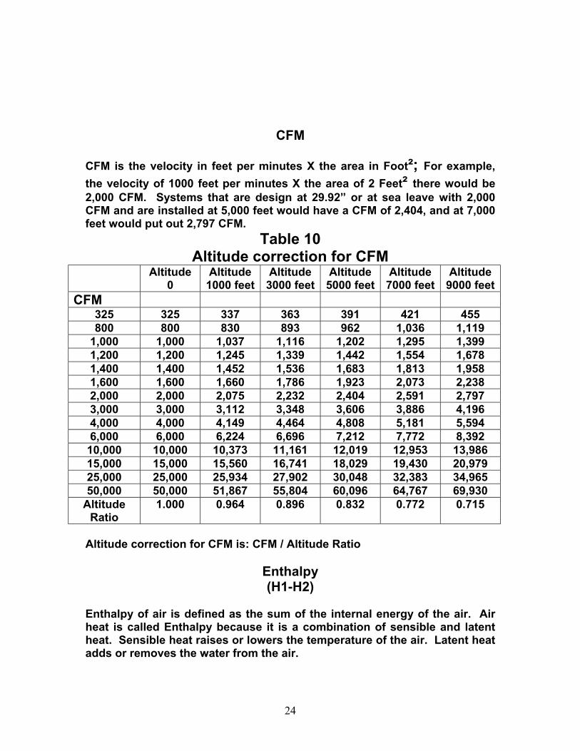
CFM CFM is the velocity in feet per minutes X the area in Foot²; For example, the velocity of 1000 feet per minutes X the area of 2 Feet² there would be 2,000 CFM. Systems that are design at 29.92” or at sea leave with 2,000 CFM and are installed at 5,000 feet would have a CFM of 2,404, and at 7,000 feet would put out 2,797 CFM.
Table 10 Altitude correction for CFM
Altitude 0
Altitude 1000 feet
Altitude 3000 feet
Altitude 5000 feet
Altitude 7000 feet
Altitude 9000 feet
CFM 325 325 337 363 391 421 455 800 800 830 893 962 1,036 1,119
1,000 1,000 1,037 1,116 1,202 1,295 1,399 1,200 1,200 1,245 1,339 1,442 1,554 1,678 1,400 1,400 1,452 1,536 1,683 1,813 1,958 1,600 1,600 1,660 1,786 1,923 2,073 2,238 2,000 2,000 2,075 2,232 2,404 2,591 2,797 3,000 3,000 3,112 3,348 3,606 3,886 4,196 4,000 4,000 4,149 4,464 4,808 5,181 5,594 6,000 6,000 6,224 6,696 7,212 7,772 8,392
10,000 10,000 10,373 11,161 12,019 12,953 13,986 15,000 15,000 15,560 16,741 18,029 19,430 20,979 25,000 25,000 25,934 27,902 30,048 32,383 34,965 50,000 50,000 51,867 55,804 60,096 64,767 69,930
Altitude Ratio
1.000 0.964 0.896 0.832 0.772 0.715
Altitude correction for CFM is: CFM / Altitude Ratio
Enthalpy (H1-H2)
Enthalpy of air is defined as the sum of the internal energy of the air. Air heat is called Enthalpy because it is a combination of sensible and latent heat. Sensible heat raises or lowers the temperature of the air. Latent heat adds or removes the water from the air.
24
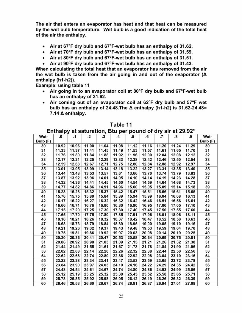
The air that enters an evaporator has heat and that heat can be measured by the wet bulb temperature. Wet bulb is a good indication of the total heat of the air the enthalpy.
• Air at 67ºF dry bulb and 67ºF-wet bulb has an enthalpy of 31.62. • Air at 70ºF dry bulb and 67ºF-wet bulb has an enthalpy of 31.59. • Air at 80ºF dry bulb and 67ºF-wet bulb has an enthalpy of 31.51. • Air at 90ºF dry bulb and 67ºF-wet bulb has an enthalpy of 31.43.
When calculating the total heat that an evaporator has removed from the air the wet bulb is taken from the air going in and out of the evaporator (∆ enthalpy (h1-h2)). Example: using table 11
• Air going in to an evaporator coil at 80ºF dry bulb and 67ºF-wet bulb has an enthalpy of 31.62.
• Air coming out of an evaporator coil at 62ºF dry bulb and 57ºF wet bulb has an enthalpy of 24.48.The ∆ enthalpy (h1-h2) is 31.62-24.48= 7.14 ∆ enthalpy.
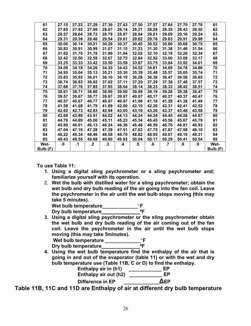
Table 11
Enthalpy at saturation, Btu per pound of dry air at 29.92” Wet-
Bulb (F) .0 .1 .2 .3 .4 .5 .6 .7 .8 .9 Wet-
Bulb (F) 30 31 32 33 34
10.92 11.33 11.76 12.17 12.59
10.96 11.37 11.80 12.21 12.63
11.00 11.41 11.84 12.25 12.67
11.04 11.45 11.88 12.29 12.71
11.08 11.49 11.92 12.33 12.75
11.12 11.53 11.96 12.38 12.80
11.16 11.57 12.00 12.42 12.84
11.20 11.61 12.04 12.46 12.88
11.24 11.65 12.08 12.50 12.92
11.29 11.70 12.12 12.54 12.97
30 31 32 33 34
35 36 37 38 39
13.01 13.44 13.87 14.32 14.77
13.05 13.48 13.92 14.36 14.82
13.09 13.53 13.96 14.41 14.86
13.14 13.57 14.01 14.45 14.91
13.18 13.61 14.05 14.50 14.96
13.22 13.66 14.10 14.54 15.00
13.27 13.70 14.14 14.59 15.05
13.31 13.74 14.19 14.64 15.09
13.35 13.79 14.23 14.68 15.14
13.40 13.83 14.28 14.73 15.18
35 36 37 38 39
40 41 42 43 44
15.23 15.70 16.17 16.66 17.15
15.28 15.75 16.22 16.71 17.20
15.32 15.80 16.27 16.76 17.25
15.37 15.84 16.32 16.80 17.30
15.42 15.89 16.32 16.80 17.30
15.47 15.94 16.42 16.90 17.40
15.51 15.99 16.46 16.95 17.45
15.56 16.04 16.51 17.00 17.50
15.61 16.08 16.56 17.05 17.55
15.65 16.13 16.61 17.10 17.60
40 41 42 43 44
45 46 47 48 49
17.65 18.16 18.68 19.21 19.75
17.70 18.21 18.73 19.26 19.81
17.75 18.26 18.79 19.32 19.86
17.80 18.32 18.84 19.37 19.92
17.85 18.37 18.89 19.43 19.97
17.91 18.42 18.95 19.48 20.03
17.96 18.47 19.00 19.53 20.08
18.01 18.52 19.05 19.59 20.14
18.06 18.58 19.10 19.64 20.19
18.11 18.63 19.16 19.70 20.25
45 46 47 48 49
50 51 52 53 54
20.30 20.86 21.44 22.02 22.62
20.36 20.92 21.49 22.08 22.68
20.41 20.98 21.55 22.14 22.74
20.47 21.03 21.61 22.20 22.80
20.53 21.09 21.67 22.26 22.86
20.58 21.15 21.73 22.32 22.92
20.64 21.21 21.78 22.38 22.98
20.69 21.26 21.84 22.44 23.04
20.75 21.32 21.90 22.50 23.10
20.81 21.38 21.96 22.56 23.16
50 51 52 53 54
55 56 57 58 59
23.22 23.84 24.48 25.12 25.78
23.28 23.90 24.54 25.19 25.85
23.34 23.97 24.61 25.25 25.92
23.41 24.03 24.67 25.32 25.98
23.47 24.10 24.74 25.38 26.05
23.53 24.16 24.80 25.45 26.12
23.59 24.22 24.86 25.52 26.19
23.65 24.29 24.93 25.58 26.26
23.72 24.35 24.99 25.65 26.32
23.78 24.42 25.06 25.71 26.39
55 56 57 58 59
60 26.46 26.53 26.60 26.67 26.74 26.81 26.87 26.94 27.01 27.08 60
25
61 62 63 64
27.15 27.85 28.57 29.31
27.22 27.92 28.64 29.39
27.29 27.99 28.72 29.46
27.36 28.07 28.79 29.54
27.43 28.14 28.87 29.61
27.50 28.21 28.94 29.62
27.57 28.28 29.01 29.76
27.64 28.35 29.09 29.83
27.70 28.43 29.16 29.91
27.78 28.50 29.24 29.98
61 62 63 64
65 66 67 68 69
30.06 30.83 31.62 32.42 33.25
30.14 30.91 31.70 32.50 33.33
30.21 30.99 31.78 32.59 33.42
30.29 31.07 31.86 32.67 33.50
30.37 31.15 31.94 32.75 33.59
30.45 31.23 32.02 32.84 33.67
30.52 31.30 32.10 32.92 33.75
30.60 31.38 32.18 33.00 33.84
30.68 31.46 32.26 33.08 33.92
30.75 31.54 32.34 33.17 34.01
65 66 67 68 69
70 71 72 73 74
34.09 34.95 35.83 36.74 37.66
34.18 35.04 35.92 36.83 37.76
34.26 35.13 36.01 36.92 37.85
34.35 35.21 36.10 37.02 37.95
34.43 35.30 36.19 37.11 38.04
34.52 35.39 36.28 37.20 38.14
34.61 35.48 36.38 37.29 38.23
34.69 35.57 36.47 37.38 38.33
34.78 35.65 36.56 37.48 38.42
34.86 35.74 36.65 37.57 38.51
70 71 72 73 74
75 76 77 78 79
38.61 39.57 40.57 41.58 42.62
38.71 39.67 40.67 41.68 42.73
38.80 39.77 40.77 41.79 42.83
38.90 39.87 40.87 41.89 42.94
39.00 39.97 40.97 42.00 43.05
39.09 40.07 41.08 42.10 43.16
39.19 40.17 41.18 42.20 43.26
39.28 40.27 41.28 42.31 43.37
39.38 40.37 41.38 42.41 43.48
39.47 40.47 41.48 42.52 43.58
75 76 77 78 79
80 81 82 83 84 85
43.69 44.78 45.90 47.04 48.22 49.43
43.80 44.89 46.01 47.16 48.34 49.55
43.91 45.00 46.13 47.28 48.46 49.68
44.02 45.11 46.24 47.39 48.58 49.80
44.13 45.23 46.36 47.51 48.70 49.92
44.24 45.34 46.48 47.63 48.82 50.04
44.34 45.45 46.59 47.75 48.95 50.17
44.45 45.56 46.70 47.87 49.07 50.29
44.56 45.67 46.81 47.98 49.19 50.41
44.67 45.79 46.93 48.10 49.31 50.54
80 81 82 83 84 85
Wet-Bulb (F)
.0 .1 .2 .3 .4 .5 .6 .7 .8 .9 Wet-Bulb (F)
To use Table 11:
1. Using a digital sling psychrometer or a sling psychrometer and; familiarize yourself with its operation.
2. Wet the bulb with distilled water for a sling psychrometer; obtain the wet bulb and dry bulb reading of the air going into the fan coil. Leave the psychrometer in the air until the wet bulb stops moving (this may take 5 minutes). Wet bulb temperature_____________°F Dry bulb temperature ºF
3. Using a digital sling psychrometer or the sling psychrometer obtain the wet bulb and dry bulb reading of the air coming out of the fan coil. Leave the psychrometer in the air until the wet bulb stops moving (this may take 5minutes). Wet bulb temperature _____________°F Dry bulb temperature ºF
4. Using the wet bulb temperature find the enthalpy of the air that is going in and out of the evaporator (table 11) or with the wet and dry bulb temperature use (Table 11B, C or D) to find the enthalpy.
Enthalpy air in (h1) ____________ EP Enthalpy air out (h2) ____________ EP Difference in EP _____________∆EP
Table 11B, 11C and 11D are Enthalpy of air at different dry bulb temperature
26
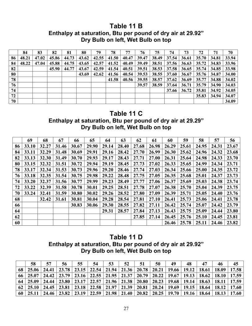
Table 11 B Enthalpy at saturation, Btu per pound of dry air at 29.92”
Dry Bulb on left, Wet Bulb on top
84 83 82 81 80 79 78 77 76 75 74 73 72 71 70 86 48.21 47.02 45.86 44.73 43.62 42.55 41.50 40.47 39.47 38.49 37.54 36.61 35.70 34.81 33.94 84 48.22 47.04 45.88 44.75 43.65 42.57 41.52 40.49 39.49 38.51 37.56 36.63 35.72 34.83 33.96 82 45.90 44.77 43.67 42.59 41.54 40.51 39.51 38.53 37.58 36.65 35.74 34.85 33.98 80 43.69 42.62 41.56 40.54 39.53 38.55 37.60 36.67 35.76 34.87 34.00 78 41.58 40.56 39.55 38.57 37.62 36.69 35.77 34.88 34.02 76 39.57 38.59 37.64 36.71 35.79 34.90 34.03 74 37.66 36.72 35.81 34.92 34.05 72 35.83 34.94 34.07 70 34.09
Table 11 C
Enthalpy at saturation, Btu per pound of dry air at 29.29” Dry Bulb on left, Wet Bulb on top
69 68 67 66 65 64 63 62 61 60 59 58 57 56 86 33.10 32.27 31.46 30.67 29.90 29.14 28.40 27.68 26.98 26.29 25.61 24.95 24.31 23.67 84 33.11 32.29 31.48 30.69 29.91 29.16 28.42 27.70 26.99 26.30 25.62 24.96 24.32 23.68 82 33.13 32.30 31.49 30.70 29.93 29.17 28.43 27.71 27.00 26.31 25.64 24.98 24.33 23.70 80 33.15 32.32 31.51 30.72 29.94 29.19 28.45 27.73 27.02 26.33 25.65 24.99 24.34 23.71 78 33.17 32.34 31.53 30.73 29.96 29.20 28.46 27.74 27.03 26.34 25.66 25.00 24.35 23.72 76 33.18 32.35 31.54 30.75 29.98 29.22 28.48 27.75 27.05 26.35 25.68 25.01 24.37 23.73 74 33.20 32.37 31.56 30.77 29.99 29.23 28.49 27.77 27.06 26.37 25.69 25.03 24.38 23.74 72 33.22 32.39 31.58 30.78 30.01 29.25 28.51 27.78 27.07 26.38 25.70 25.04 24.39 23.75 70 33.24 32.41 31.59 30.80 30.02 29.26 28.52 27.80 27.09 26.39 25.71 25.05 24.40 23.76 68 32.42 31.61 30.81 30.04 29.28 28.54 27.81 27.10 26.41 25.73 25.06 24.41 23.78 66 30.83 30.06 29.30 28.55 27.82 27.11 26.42 25.74 25.07 24.42 23.79 64 29.31 28.57 27.84 27.13 26.43 25.75 25.09 24.44 23.80 62 27.85 27.14 26.45 25.76 25.10 24.45 23.81 60 26.46 25.78 25.11 24.46 23.82
Table 11 D
Enthalpy at saturation, Btu per pound of dry air at 29.92” Dry Bulb on left, Wet Bulb on top
58 57 56 55 54 53 52 51 50 49 48 47 46 45 68 25.06 24.41 23.78 23.15 22.54 21.94 21.36 20.78 20.21 19.66 19.12 18.61 18.09 17.58 66 25.07 24.42 23.79 23.16 22.55 21.95 21.37 20.79 20.22 19.67 19.13 18.62 18.10 17.59 64 25.09 24.44 23.80 23.17 22.57 21.96 21.38 20.80 20.23 19.68 19.14 18.63 18.11 17.59 62 25.10 24.45 23.81 23.18 22.58 21.97 21.39 20.81 20.24 19.69 19.15 18.64 18.12 17.60 60 25.11 24.46 23.82 23.19 22.59 21.98 21.40 20.82 20.25 19.70 19.16 18.64 18.13 17.60
27
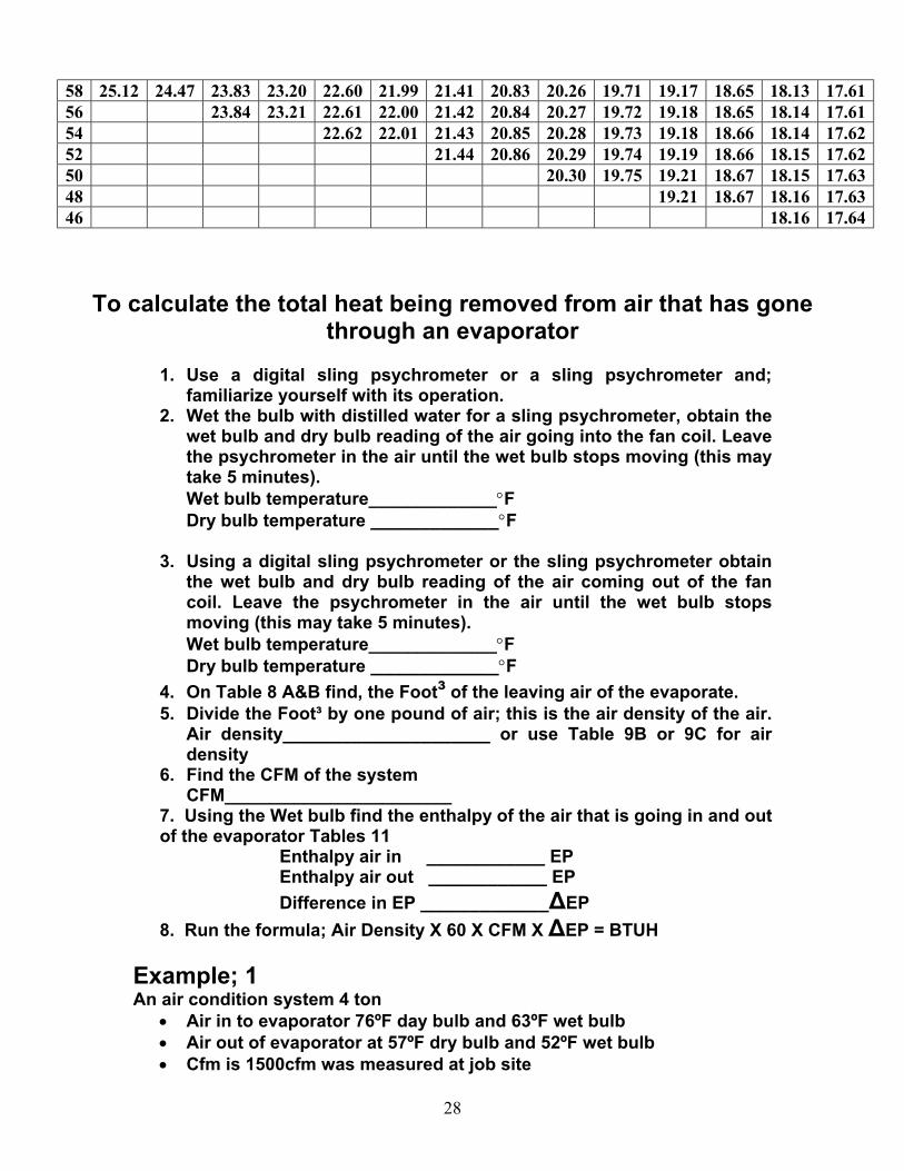
58 25.12 24.47 23.83 23.20 22.60 21.99 21.41 20.83 20.26 19.71 19.17 18.65 18.13 17.61 56 23.84 23.21 22.61 22.00 21.42 20.84 20.27 19.72 19.18 18.65 18.14 17.61 54 22.62 22.01 21.43 20.85 20.28 19.73 19.18 18.66 18.14 17.62 52 21.44 20.86 20.29 19.74 19.19 18.66 18.15 17.62 50 20.30 19.75 19.21 18.67 18.15 17.63 48 19.21 18.67 18.16 17.63 46 18.16 17.64
To calculate the total heat being removed from air that has gone through an evaporator
1. Use a digital sling psychrometer or a sling psychrometer and;
familiarize yourself with its operation. 2. Wet the bulb with distilled water for a sling psychrometer, obtain the
wet bulb and dry bulb reading of the air going into the fan coil. Leave the psychrometer in the air until the wet bulb stops moving (this may take 5 minutes). Wet bulb temperature_____________°F Dry bulb temperature _____________°F
3. Using a digital sling psychrometer or the sling psychrometer obtain the wet bulb and dry bulb reading of the air coming out of the fan coil. Leave the psychrometer in the air until the wet bulb stops moving (this may take 5 minutes). Wet bulb temperature_____________°F Dry bulb temperature _____________°F
4. On Table 8 A&B find, the Foot³ of the leaving air of the evaporate. 5. Divide the Foot³ by one pound of air; this is the air density of the air.
Air density_____________________ or use Table 9B or 9C for air density
6. Find the CFM of the system CFM_______________________
7. Using the Wet bulb find the enthalpy of the air that is going in and out of the evaporator Tables 11
Enthalpy air in ____________ EP Enthalpy air out ____________ EP Difference in EP _____________∆EP
8. Run the formula; Air Density X 60 X CFM X ∆EP = BTUH Example; 1 An air condition system 4 ton
• Air in to evaporator 76ºF day bulb and 63ºF wet bulb • Air out of evaporator at 57ºF dry bulb and 52ºF wet bulb • Cfm is 1500cfm was measured at job site
28
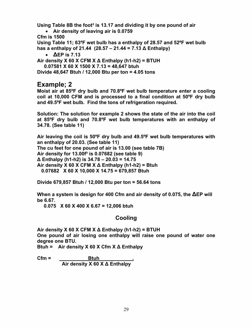
Using Table 8B the foot³ is 13.17 and dividing it by one pound of air • Air density of leaving air is 0.0759
Cfm is 1500 Using Table 11; 63ºF wet bulb has a enthalpy of 28.57 and 52ºF wet bulb has a enthalpy of 21.44 (28.57 – 21.44 = 7.13 ∆ Enthalpy)
• ∆EP is 7.13 Air density X 60 X CFM X ∆ Enthalpy (h1-h2) = BTUH 0.07581 X 60 X 1500 X 7.13 = 48,647 btuh Divide 48,647 Btuh / 12,000 Btu per ton = 4.05 tons Example; 2 Moist air at 85ºF dry bulb and 70.8ºF wet bulb temperature enter a cooling coil at 10,000 CFM and is processed to a final condition at 50ºF dry bulb and 49.5ºF wet bulb. Find the tons of refrigeration required. Solution: The solution for example 2 shows the state of the air into the coil at 85ºF dry bulb and 70.8ºF wet bulb temperatures with an enthalpy of 34.78. (See table 11) Air leaving the coil is 50ºF dry bulb and 49.5ºF wet bulb temperatures with an enthalpy of 20.03. (See table 11) The cu feet for one pound of air is 13.00 (see table 7B) Air density for 13.00f³ is 0.07682 (see table 9) ∆ Enthalpy (h1-h2) is 34.78 – 20.03 = 14.75 Air density X 60 X CFM X ∆ Enthalpy (h1-h2) = Btuh 0.07682 X 60 X 10,000 X 14.75 = 679,857 Btuh Divide 679,857 Btuh / 12,000 Btu per ton = 56.64 tons When a system is design for 400 Cfm and air density of 0.075, the ∆EP will be 6.67.
0.075 X 60 X 400 X 6.67 = 12,006 btuh
Cooling Air density X 60 X CFM X ∆ Enthalpy (h1-h2) = BTUH One pound of air losing one enthalpy will raise one pound of water one degree one BTU. Btuh = Air density X 60 X Cfm X ∆ Enthalpy Cfm = Btuh . Air density X 60 X ∆ Enthalpy
29
30
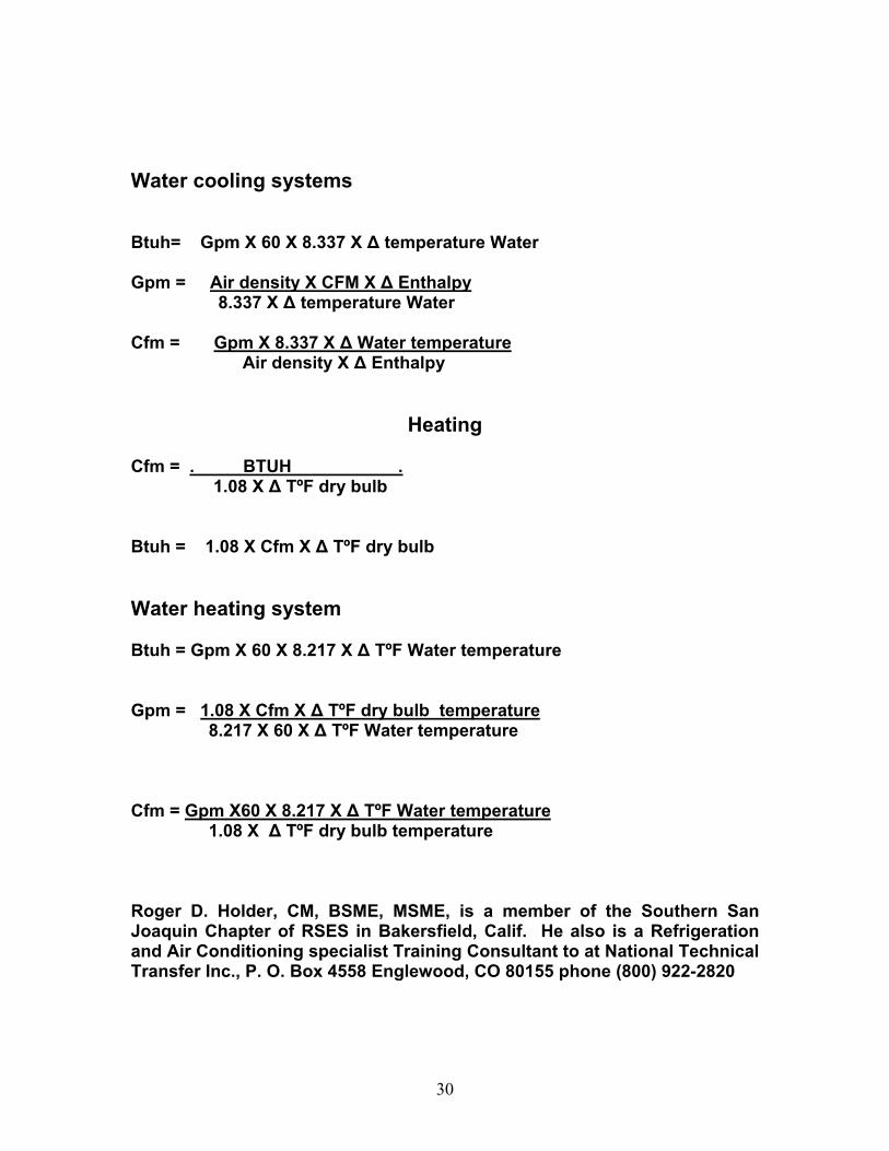
Water cooling systems Btuh= Gpm X 60 X 8.337 X ∆ temperature Water Gpm = Air density X CFM X ∆ Enthalpy 8.337 X ∆ temperature Water Cfm = Gpm X 8.337 X ∆ Water temperature Air density X ∆ Enthalpy
Heating Cfm = . BTUH . 1.08 X ∆ TºF dry bulb Btuh = 1.08 X Cfm X ∆ TºF dry bulb Water heating system Btuh = Gpm X 60 X 8.217 X ∆ TºF Water temperature Gpm = 1.08 X Cfm X ∆ TºF dry bulb temperature 8.217 X 60 X ∆ TºF Water temperature Cfm = Gpm X60 X 8.217 X ∆ TºF Water temperature 1.08 X ∆ TºF dry bulb temperature Roger D. Holder, CM, BSME, MSME, is a member of the Southern San Joaquin Chapter of RSES in Bakersfield, Calif. He also is a Refrigeration and Air Conditioning specialist Training Consultant to at National Technical Transfer Inc., P. O. Box 4558 Englewood, CO 80155 phone (800) 922-2820