chapter three materials and methods - university of...
TRANSCRIPT
51
Chapter Three
Materials and Methods
52
3.1 Materials
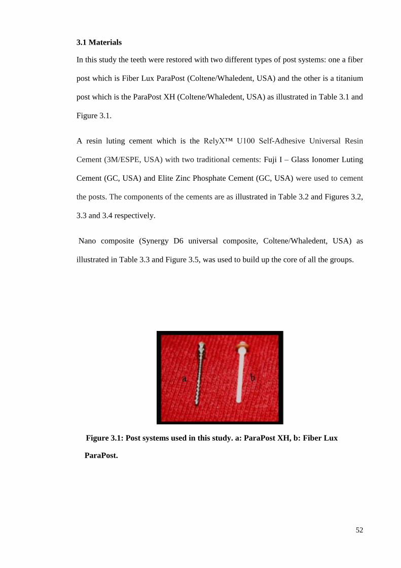
In this study the teeth were restored with two different types of post systems: one a fiber
post which is Fiber Lux ParaPost (Coltene/Whaledent, USA) and the other is a titanium
post which is the ParaPost XH (Coltene/Whaledent, USA) as illustrated in Table 3.1 and
Figure 3.1.
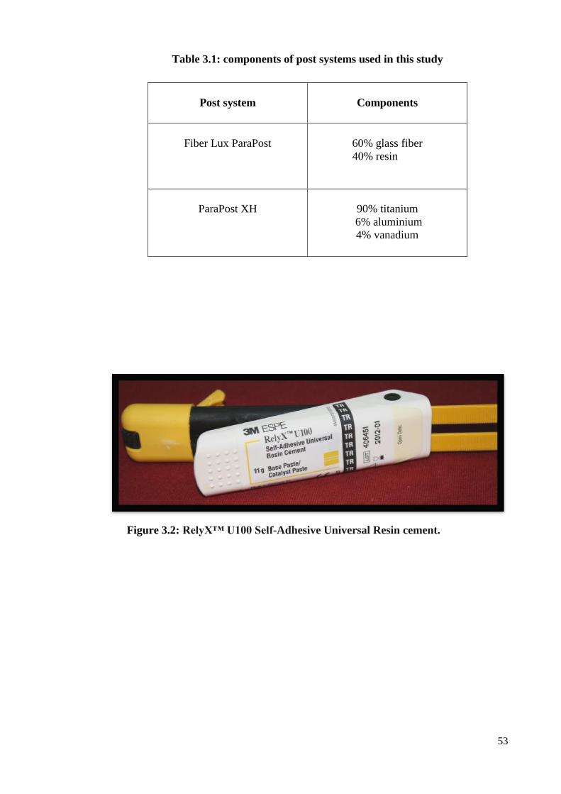
A resin luting cement which is the RelyX™ U100 Self-Adhesive Universal Resin
Cement (3M/ESPE, USA) with two traditional cements: Fuji I – Glass Ionomer Luting
Cement (GC, USA) and Elite Zinc Phosphate Cement (GC, USA) were used to cement
the posts. The components of the cements are as illustrated in Table 3.2 and Figures 3.2,
3.3 and 3.4 respectively.
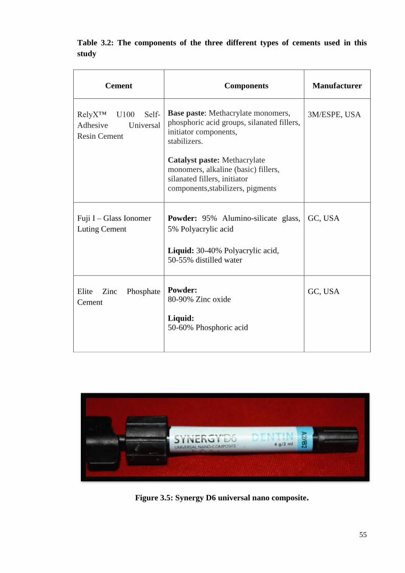
Nano composite (Synergy D6 universal composite, Coltene/Whaledent, USA) as
illustrated in Table 3.3 and Figure 3.5, was used to build up the core of all the groups.
Figure 3.1: Post systems used in this study. a: ParaPost XH, b: Fiber Lux
ParaPost.
53
Table 3.1: components of post systems used in this study
Figure 3.2: RelyX™ U100 Self-Adhesive Universal Resin cement.
Post system
Components
Fiber Lux ParaPost
60% glass fiber
40% resin
ParaPost XH
90% titanium
6% aluminium
4% vanadium

54
Figure 3.3: Fuji I –Glass Ionomer Luting Cement.
Figure 3.4: Elite Zinc Phosphate Cement.
55
Table 3.2: The components of the three different types of cements used in this
study
Figure 3.5: Synergy D6 universal nano composite.
Cement
Components
Manufacturer
RelyX™ U100 Self-
Adhesive Universal
Resin Cement
Base paste: Methacrylate monomers,
phosphoric acid groups, silanated fillers,
initiator components,
stabilizers.
Catalyst paste: Methacrylate
monomers, alkaline (basic) fillers,
silanated fillers, initiator
components,stabilizers, pigments
3M/ESPE, USA
Fuji I – Glass Ionomer
Luting Cement
Powder: 95% Alumino-silicate glass,
5% Polyacrylic acid
Liquid: 30-40% Polyacrylic acid,
50-55% distilled water
GC, USA
Elite Zinc Phosphate
Cement
Powder:
80-90% Zinc oxide
Liquid: 50-60% Phosphoric acid
GC, USA

56
Table 3.3: The components of the composite core buildup material
3.2 Method
3.2.1 Tooth Collection
One hundred and fifty extracted teeth were collected. Teeth were immersed in 0.5%
Chloramine trihydrate solution for disinfection for one week. After that, all the external
hard and soft debris were removed by using an ultrasonic scaler (Dentsply® Cavitron®
BOBCAT® PRO 130B, USA).
3.2.2 Tooth Selection
Seventy teeth were selected which involved only single-rooted mandibular premolar
teeth. Any teeth with gross caries and fractures were discarded. The buccolingual and
mesiodistal dimensions at the cementoenamel junction of each tooth were measured
with an electronic digital calliper (Mitutoyo, Japan). Those with comparable
buccolingual (7-7.5 mm) and mesiodistal (5-5.5 mm) dimensions were selected.
Buccolingual and mesiodistal radiographs were taken to check the number of canals, the
root integrity and the canal morphology of all teeth. Only caries-free teeth with straight
single canal were chosen for the investigation (Fig. 3.6).
Composite type
Components
Synergy D6 universal nano composite
Filler: Barium glass, silanized
amorphous silica
Matrix: Methacrylates

57
Figure 3.6: Mesiodistal and buccolingual radiographs
3.2.3 Decoronation of teeth
In order to obtain a standard root length for all the specimens, the crowns of teeth were
removed with a straight handpiece and disc (Hidi, England) at the CEJ perpendicular to
the long axis of the root (Fig. 3.7).
Figure 3.7 Decoronation of teeth.
58
3.2.4 Root Canal Preparation and Obturation
The remaining pulpal tissue was removed from the root canal of each tooth with barbed
broaches (Shofu, Japan). The patency of the apical foramen was determined by inserting
a size 10 K- file (NTI, Germany) through the apex. The file was drawn back into the
tooth until it is just visible at the apical foramen. The working length was set 1.0 mm
short of this file‘s length. The sectioned root face was the reference point from which all
measurements were taken. The root canals were then prepared chemomechanically
using the step-back technique (Fig. 3.8). The procedure was repeated with each canal
using larger file in order of increasing size and shaping the area of apical foramen. All
the root canal specimens were cleaned and shaped to a size 40 K-file at the apex. The
canals were irrigated with 3.0 ml of a 2.5% sodium hypochlorite (NaOCl) solution
(Clorox, Malaysia Sdn. Bhd) between each instrumentation of the canal.
After the apical preparation was finished, flaring of the canal was done using the step-
back technique. The next file used was larger than the previous one and 1mm shorter
than the working length. This procedure was repeated by using the next larger file and
1mm shorter than working length until size 55 K-file.
Each K-file kit was used only for preparation of five canals. The canals were irrigated
with 3.0 ml of a 17% ethylenediaminetetraacetic acid (EDTA System, UK) for
removing the smear layer. Then, the final irrigation was done with distilled water to
remove any trace of irrigants left in the canal. The instrumented teeth were then kept in
distilled water until the obturation time.
The canals were dried with paper points (Sure-Endo, Korea). The teeth were obturated
using the lateral condensation technique by using gutta-percha cones (Sure-Endo,
Korea) (Fig. 3.9) and resin-based canal sealer (Pulpdent Root Canal Sealer,
Coltene/Whaledent, USA) (Fig.3.10). The gutta-percha at the canal orifices was

59
vertically condensed with a heated condenser (Nordent, USA). The canal orifices were
sealed with temporary cement (Cavit™ W, 3M ESPE, USA). The teeth were then stored
in a 100% humid environment at 37° C for 24 hours to ensure full setting of the sealer.
Figure 3.8 Chemomechanical preparation of the teeth.
Figure 3.9 gutta-percha cones.
60
Figure 3.10 Pulpdent Root Canal Sealer.
3.2.4 Groups
The total samples were divided into three groups; two of them consist of 30 teeth and
were restored with two different post systems; Fiber Lux ParaPost (F) and ParaPost XH
(P).
Then each group was subdivided into 3 subgroups of 10 teeth, each one cemented with
different luting agents; RelyX™ U100 Self-Adhesive Universal Resin Cement (R), Elite
Zinc Phosphate Cement (ZP), and Fuji I- Glass Ionomer Luting Cement (GI).
For the third main group which consisted of 10 teeth only, endodontic treatment was
done only and was the control group (RCT). The groups were as illustrated in figure
3.11
61
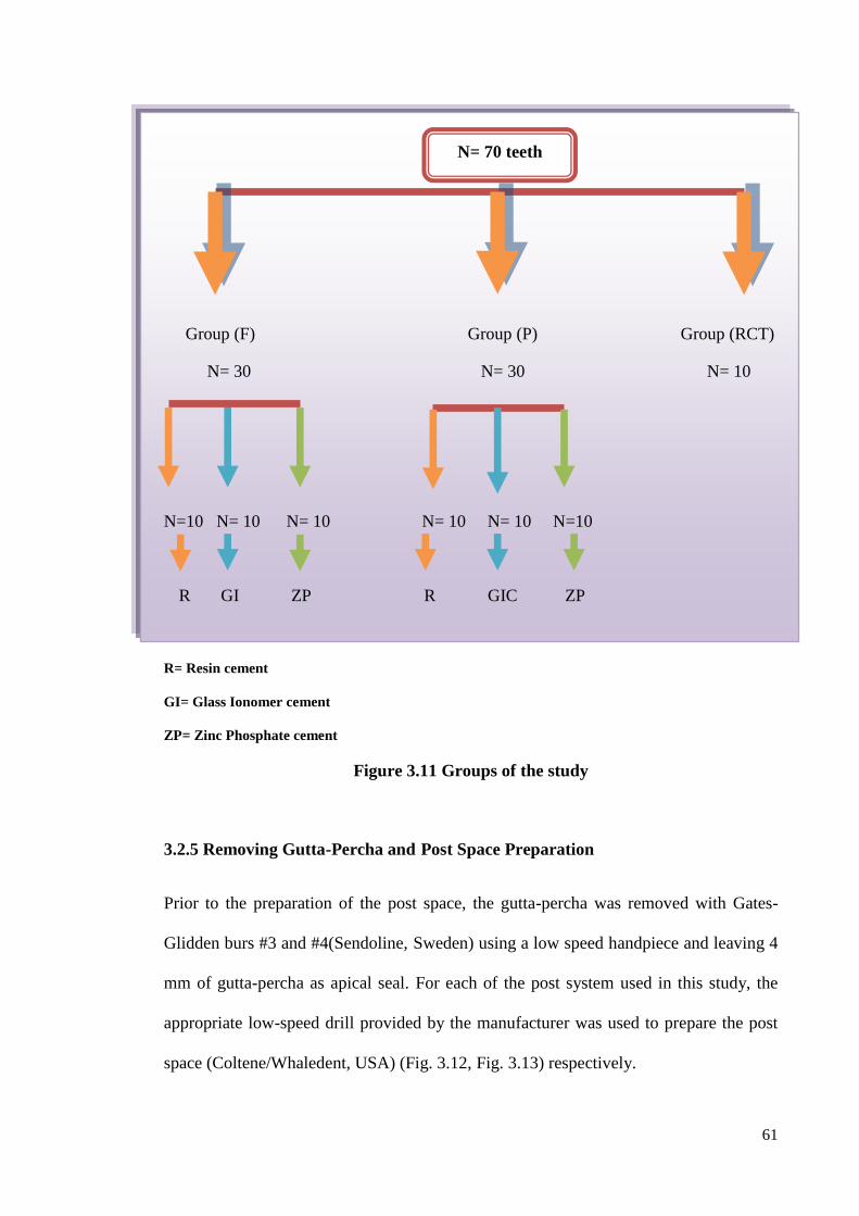
Group (F) Group (P) Group (RCT)
N= 30 N= 30 N= 10
N=10 N= 10 N= 10 N= 10 N= 10 N=10
R GI ZP R GIC ZP
R= Resin cement
GI= Glass Ionomer cement
ZP= Zinc Phosphate cement
Figure 3.11 Groups of the study
3.2.5 Removing Gutta-Percha and Post Space Preparation
Prior to the preparation of the post space, the gutta-percha was removed with Gates-
Glidden burs #3 and #4(Sendoline, Sweden) using a low speed handpiece and leaving 4
mm of gutta-percha as apical seal. For each of the post system used in this study, the
appropriate low-speed drill provided by the manufacturer was used to prepare the post
space (Coltene/Whaledent, USA) (Fig. 3.12, Fig. 3.13) respectively.
N= 70 teeth

62
The canals were irrigated by using distilled water and dried by air. After the preparation,
the resulted post space depth was 9 mm from the sectioned root surface. The post was
tried-in before cementation to ensure that the depth of the post was 9 mm.
Figure 3.12 Parapost XH with matching drill.
Figure 3.13 Fiber Lux ParaPost with matching drill

63
3.2.6 Post Cementation
The posts of each group were cemented using the RelyX™ U100 Self -Adhesive
Universal Resin Cement (3M/ESPE, USA), Elite Zinc Phosphate Cement (GC, USA),
and Fuji I – Glass Ionomer Luting Cement (GC, USA). The post was tried-in before
final cementation to ensure that the post can be inserted to a final depth of 9 mm. The
excess part of the post was then cut using a diamond bur. The posts were cemented
following the manufacturer‘s instructions while maintaining finger pressure on the post
until the cement had set.
The excess cement was then removed and the teeth were cleaned with a moist cotton
roll. All the specimens were stored in distilled water at 37°C with 100% humidity in an
incubator for two days to ensure full cement setting.
3.2.7 Core buildup
A 35% phosphoric acid gel (Swiss TEC, Coltene/Whaledent, USA) was used for
etching the root surface. According to the manufacturer‘s instructions, the etching time
used was for 15 seconds, then rinsed thoroughly with water for 20 seconds and dried by
using oil-free air. One layer of bonding agent (Swiss TEC, Coltene/Whaledent, USA)
was applied to the etched root surface using a brush with massaging movement for 20
seconds and lightly air dried. It was then cured with a halogen light (Valo, China) for 30
seconds.
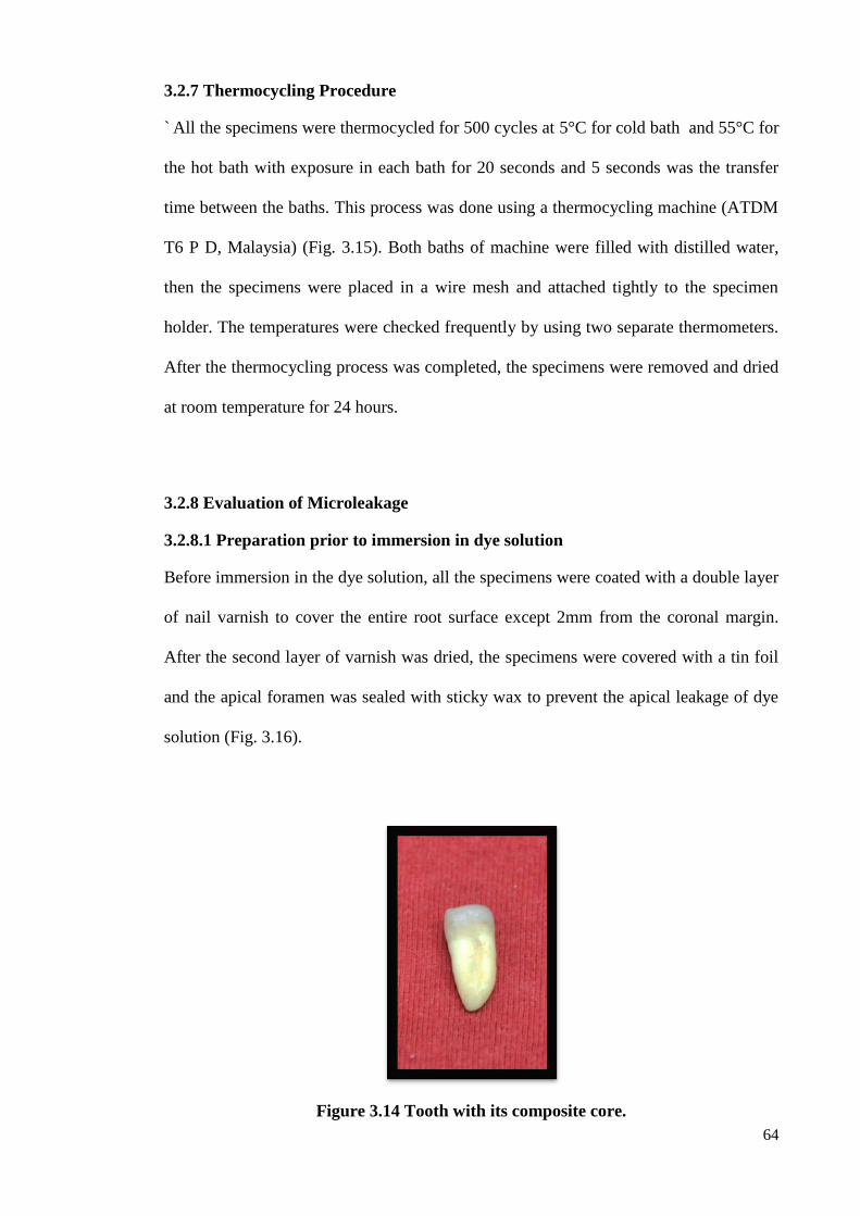
Finally, the composite (Synergy D6 universal composite, Coltene /Whaledent, USA)
was packed incrementally by using the same copper band for all the specimens to form
standardized cores and light cured for 30 seconds. They were then finished and polished
(Fig. 3.14).
64
3.2.7 Thermocycling Procedure
` All the specimens were thermocycled for 500 cycles at 5°C for cold bath and 55°C for
the hot bath with exposure in each bath for 20 seconds and 5 seconds was the transfer
time between the baths. This process was done using a thermocycling machine (ATDM
T6 P D, Malaysia) (Fig. 3.15). Both baths of machine were filled with distilled water,
then the specimens were placed in a wire mesh and attached tightly to the specimen
holder. The temperatures were checked frequently by using two separate thermometers.
After the thermocycling process was completed, the specimens were removed and dried
at room temperature for 24 hours.
3.2.8 Evaluation of Microleakage
3.2.8.1 Preparation prior to immersion in dye solution
Before immersion in the dye solution, all the specimens were coated with a double layer
of nail varnish to cover the entire root surface except 2mm from the coronal margin.
After the second layer of varnish was dried, the specimens were covered with a tin foil
and the apical foramen was sealed with sticky wax to prevent the apical leakage of dye
solution (Fig. 3.16).
Figure 3.14 Tooth with its composite core.

65
Figure 3.15 Thermocycling machine.
Figure 3.16 Tooth covered with a tin foil
66
3.2.8.2 Microleakage Test
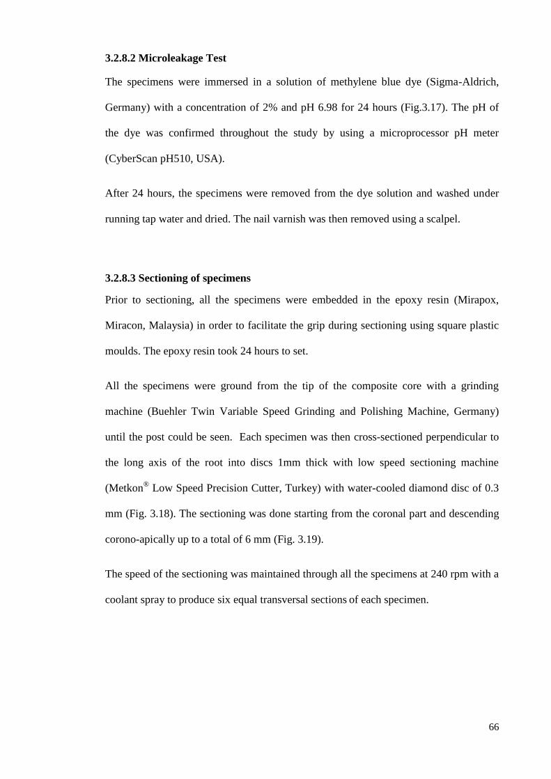
The specimens were immersed in a solution of methylene blue dye (Sigma-Aldrich,
Germany) with a concentration of 2% and pH 6.98 for 24 hours (Fig.3.17). The pH of
the dye was confirmed throughout the study by using a microprocessor pH meter
(CyberScan pH510, USA).
After 24 hours, the specimens were removed from the dye solution and washed under
running tap water and dried. The nail varnish was then removed using a scalpel.
3.2.8.3 Sectioning of specimens
Prior to sectioning, all the specimens were embedded in the epoxy resin (Mirapox,
Miracon, Malaysia) in order to facilitate the grip during sectioning using square plastic
moulds. The epoxy resin took 24 hours to set.
All the specimens were ground from the tip of the composite core with a grinding
machine (Buehler Twin Variable Speed Grinding and Polishing Machine, Germany)
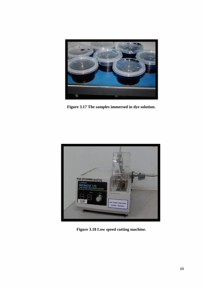
until the post could be seen. Each specimen was then cross-sectioned perpendicular to
the long axis of the root into discs 1mm thick with low speed sectioning machine
(Metkon® Low Speed Precision Cutter, Turkey) with water-cooled diamond disc of 0.3
mm (Fig. 3.18). The sectioning was done starting from the coronal part and descending
corono-apically up to a total of 6 mm (Fig. 3.19).
The speed of the sectioning was maintained through all the specimens at 240 rpm with a
coolant spray to produce six equal transversal sections of each specimen.

67
3.2.8.4 Micoleakage Evaluation Procedure
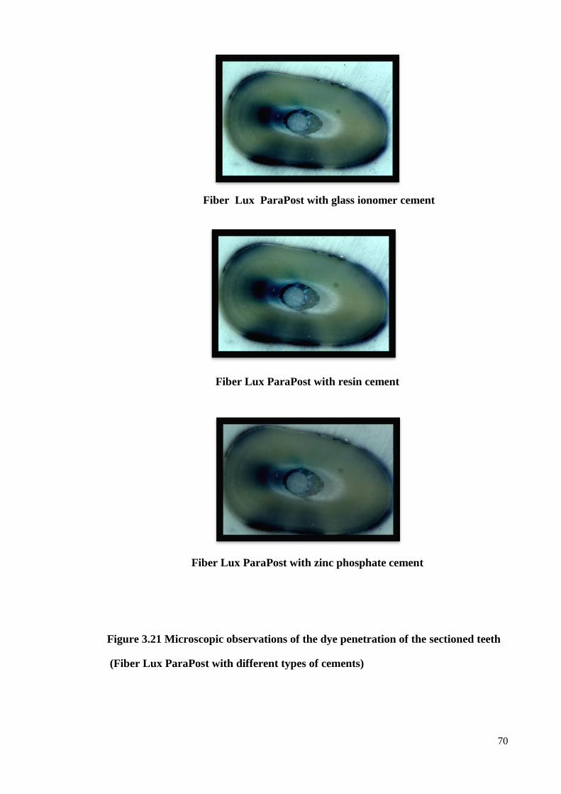
The microleakage was evaluated by investigating the coronal surface of each section
under a Stereomicroscope (Olympus, Japan) (Fig. 3.20) at 8x magnification and
photographs were taken (Figs.3.21 & 3.22). The infiltrated and the total canal area were
determined and measured in square millimetres using Cell^D imaging software for life
science (Olympus, Japan).
The degree of coronal microleakage between post and luting agent was then quantified
by calculating the dye penetration as the percentage of the methylene blue infiltrated
surface divided by the total canal area. The mean of each sample was taken and the
resultant coronal microleakage was checked statistically and compared between the
groups.
3.2.9 Reliability measurements:
Intra-examiner reliability test was done by re-evaluating randomly 10% of all samples
for two days at one week intervals without the knowledge of the previous readings. The
collected data was then statistically analyzed (Appendix IV).
3.2.10 Data Analysis
The Statistical Packages for Social Science (SPSS) version 12.0 was used in this study
to analyse the collected data. The collected data was subjected to statistical analysis
using Two-way ANOVA test.
However, the homogeneity of the assumption was not similar. Thus, the nonparametric
analysis test (Kruskal–Wallis test) was used with setting the significance of test at 5%
(p<0.05).
68
Figure 3.17 The samples immersed in dye solution.
Figure 3.18 Low speed cutting machine.

69
Figure 3.19 Six equal transversal sections.
Figure 3.20 Stereomicroscope.
70
Fiber Lux ParaPost with glass ionomer cement
Fiber Lux ParaPost with resin cement
Fiber Lux ParaPost with zinc phosphate cement
Figure 3.21 Microscopic observations of the dye penetration of the sectioned teeth
(Fiber Lux ParaPost with different types of cements)

71
Parapost XH with glass ionomer cement
Parapost XH with resin cement
Parapost XH with zinc phosphate cement
Figure 3.22 Microscopic observations of the dye penetration of the sectioned teeth
(Parapost XH with different types of cements)