chapter thirteen flexible pavement design · 2015-03-10 · 13-1 december 2007 flexible pavement...
TRANSCRIPT
December 2007
CCHHAAPPTTEERR TTHHIIRRTTEEEENN
FFLLEEXXIIBBLLEE PPAAVVEEMMEENNTT DDEESSIIGGNN

13-i December 2007 FLEXIBLE PAVEMENT DESIGN
Chapter Thirteen
TABLE OF CONTENTS Section Page 13-1 INTRODUCTION ......................................................................................................... 13-1 13-1.1 Purpose ............................................................................................................ 13-1 13-1.2 Pavement Design History................................................................................ 13-1 13-1.3 Flexible Pavement – Definition....................................................................... 13-1 13-2 DATA COLLECTION .................................................................................................. 13-2 13-2.1 Traffic Data ..................................................................................................... 13-2 13-2.2 Pavement Management Section ...................................................................... 13-2 13-2.3 Project History................................................................................................. 13-2 13-2.4 Field Data ........................................................................................................ 13-2 13-3 PAVEMENT TREATMENTS ...................................................................................... 13-3 13-3.1 Highway Development.................................................................................... 13-3 13-3.2 Highway Rehabilitation................................................................................... 13-3 13-3.3 Highway Preservation ..................................................................................... 13-3 13-4 RECYCLING BITUMINOUS PAVEMENT ................................................................ 13-3 13-4.1 Full Depth Reclamation with Foamed Asphalt ................................................ 13-4 13-4.2 Full Depth Reclamation with Cement .............................................................. 13-5 13-4.3 Plant Mix Recycled Asphalt Pavement (PMRAP)........................................... 13-5 13-4.4 Cold-in-Place Recycled Pavement (CIPR)....................................................... 13-6 13-4.5 Weather Limitations ......................................................................................... 13-6 13-4.6 Curing............................................................................................................... 13-7 13-4.7 Design............................................................................................................... 13-7 13-5 FROST CONSIDERATIONS ....................................................................................... 13-8 13-5.1 Design Information........................................................................................... 13-9 13-5.1.1 Site Inspection ................................................................................... 13-9 13-5.1.2 Subsurface Investigations and Soils Classification ........................... 13-9 13.5.1.3 Design Freezing Index and Frost Depth ............................................ 13-9 13-5.2 Mitigating Frost Action .................................................................................. 13-10 13-5.2.1 Frost Heaving .................................................................................. 13-10 13-5.2.2 Thaw Weakening............................................................................. 13-11 13-6 PAVEMENT DESIGN................................................................................................ 13-11 13-6.1 Design Software .............................................................................................. 13-11 13-6.2 Pavement Structure Thickness ........................................................................ 13-11 13-6.3 Structural Number Design - Input Variables................................................... 13-12 13-6.3.1 18-kip ESAL’s................................................................................. 13-12 13-6.3.2 Initial Serviceability ........................................................................ 13-13 13-6.3.3 Terminal Serviceability ................................................................... 13-13

13-ii December 2007 FLEXIBLE PAVEMENT DESIGN 13-6.3.4 Reliability ........................................................................................ 13-13 13-6.3.5 Overall Standard Deviation ............................................................. 13-14 13-6.3.6 Subgrade Resilient Modulus ........................................................... 13-14 13-6.3.7 Number of Construction Stages ...................................................... 13-15 13-6.4 Specified Thickness Design Method................................................................ 13-15 13-6.4.1 Structural Layer Coefficients ........................................................... 13-15 13-6.5 Pavement Design Resources ............................................................................ 13-15 13-7 HOT MIX ASPHALT.................................................................................................. 13-16 13-7.1 HMA Layer Thicknesses................................................................................. 13-16 13-7.2 Weather Limitations ........................................................................................ 13-16 13-7.3 Smoothness...................................................................................................... 13-17 13-8 SHOULDERS .............................................................................................................. 13-17 13-8.1 Shoulder Features .............................................................................................. 13-17 13-8.2 Shoulder Design ................................................................................................ 13-18 13-9 CONTRACT DOCUMENTS....................................................................................... 13-18 APPENDIX
Figure 13-1 Traffic Request Form Figure 13-2 Maine Design Freezing Index Figure 13-3 Frost Depth Chart Figure 13-4 Layer Coefficients for Recycled Material Figure 13-5 SP 403 Request Form

13-1 December 2007 FLEXIBLE PAVEMENT DESIGN
Chapter Thirteen
FLEXIBLE PAVEMENT DESIGN 13-1 INTRODUCTION 13-1.1 Purpose This chapter will provide pavement design policies and guidance in order for the highway designer to effectively complete the pavement design on a given project. Effective pavement design begins with proper project scoping and includes pavement and roadway data collection and analysis, identification of alternative treatments and selection of the most economical treatment, as well as other steps described in this chapter. The basic information is provided here. For more detailed information please see the references and resources provided. A pavement design needs to be completed during the early phase of project development. This step ensures that pavement design is used to calculate project cost rather than project cost dictating pavement design. 13-1.2 Pavement Design History In the late 1950’s, AASHO (American Association of State Highway Officials) conducted tests on flexible and rigid pavements in Ottawa, Illinois to determine how traffic contributed to the deterioration of highway pavements. The information obtained was crucial in advancing the knowledge of pavement structural design, pavement performance, load equivalencies, climate effects, and much more.
The results from the AASHO road test were used to develop empirical equations to be used for the design of pavement structures and to develop structural pavement design guides, including the AASHTO Guide for the Design of Pavement Structures. MaineDOT currently uses the 1993 version of that guide for pavement design. 13-1.3 Flexible Pavement – Definition A flexible pavement structure typically consists of layers of different materials that increase with strength as you move towards the surface (weakest layer on the bottom, strongest layer at the surface). A flexible pavement relies on a layered system to distribute traffic loads over the subgrade. The load carrying capacity of a flexible pavement is brought about by the load-distributing characteristics of each layer in the layered system. The layers of a flexible pavement structure typically consists of hot mix asphalt (HMA) at the surface, with a stabilized base, base course gravel, and/or subbase course gravel.

13-2 December 2007 FLEXIBLE PAVEMENT DESIGN 13-2 DATA COLLECTION FOR PAVEMENT DESIGN The following sections contain information that can be collected early in the pavement design process to help determine the necessary scope of work and the treatment selection for the pavement structure. 13-2.1 Traffic Data Traffic data is requested from the Bureau of Planning using the form in Figure 13-1. The information reported back to the pavement designer on the Traffic Data sheet includes AADT, truck volumes, and the 18-kip Equivalent values at P 2.0 and P 2.5. The 18-kip Equivalent value is needed to calculate the design ESAL’s for the pavement design and FWD Analysis. 13-2.2 Pavement Management Section Pavement distress data is collected on Federal and State owned roads on a two year cycle using an ARAN (Automated Road Analyzer). The data collected includes images of the roadway, pavement distresses such as rut depth and cracking, and ride quality information. This data is collected and managed by the Pavement Management Section in the Bureau of Planning. This data should be examined to identify existing pavement distresses. These distresses should always be verified with field checks and the appropriate investigations to determine best approach to mitigating those distresses. 13-2.3 Project History All available historical information should be investigated before beginning the design of the pavement structure. The following are sources that can be used to find historical data for roadway projects:
• The Vault – The vault contains as-built plans for projects back as far as the 1940’s. The usefulness of this information depends on what can be found and what type of project is being contemplated. Most of these plans have been scanned and are now available electronically via the E-Plans Archive on the MaineDOT Intranet page or at the following link: http://dot0dta1asiis03/plansweb/dpr.asp. The electronic as-built plans contain the plan views, typicals, notes and drainage sheets. Cross sections are available on microfiche film. The microfiche reels are located in the vault and the viewer is located in Room 419 at the Augusta office.
• TIDE - Project history information is available through TIDE. This information generally only goes back to projects done since 1990.
• Department Resources – Many construction and maintenance personnel have a long personal history with a particular area or road. Maintenance personnel are an excellent resource for gathering information on existing drainage, frost, or pavement problems.
13-2.4 Field Data Subsurface information should be collected on all projects requiring a pavement design. The amount of subsurface information needed greatly depends on the scope and location of the project. The geotechnical team member can make recommendations for and coordinate the subsurface exploration program. Field information that should be considered for the pavement design includes:

13-3 December 2007 FLEXIBLE PAVEMENT DESIGN
• Falling Weight Deflectometer (FWD- for pavement condition and the Resilient Modulus • Borings – to determine the soil types, layer thicknesses, and material properties • Groundwater Elevations • Subgrade Soil Type – to determine the anticipated foundation support for the pavement
structure as well as construction equipment. • Areas of Distress and Distress Type – Structural or functional distress • Frost depths , Frost heave locations, Thaw weakening locations • Existing aggregate quality – to determine if it meets MaineDOT Standard Specifications
13-3 PAVEMENT TREATMENTS The Department utilizes a variety of different pavement treatments depending on the roadway facility and the work type associated with each facility. Roadway facilities include the Interstate, Urban Highways, Minor Collectors, and Rural Highways. Work types for each of these facilities include Development, Preservation, and Rehabilitation. 13-3.1 Highway Development Development projects are those where there is a creation or substantial replacement of a transportation facility that results in a functional or structural upgrade. Development projects include new construction and reconstruction of a roadway. The pavement will be new for the full depth. 13-3.2 Highway Rehabilitation Rehabilitation projects are those where the existing structural core of a facility is restored to a previous level of service. Pavement treatments for rehabilitation projects include recycling of existing materials, highway widening with an overlay, and structural overlays. 13-3.3 Highway Preservation Preservation projects are those where the facility’s functional or structural integrity and appearance is maintained. Pavement treatments for preservation projects include overlays, chip seals, crack sealing, Maintenance Surface Treatments (MST), microsurfacing, and mill and fills. 13-4 RECYCLING BITUMINOUS ASPHALT PAVEMENT Recycling and reusing hot mix asphalt pavements can provide excellent engineering, economic, and environmental benefits for highway rehabilitation and reconstruction projects. In the recycling process, the existing hot mix asphalt of a structurally failed pavement is uniformly pulverized or processed and blended with asphalt binder or emulsion to produce a new, stronger, stabilized base course gravel. For economic reasons, recycled materials should be considered first for the pavement design in all highway rehabilitation and reconstruction (full or partial) projects. Both asphalt and aggregate are a non-renewable resource, and as resources diminish, costs of these materials increase. The supply of suitable aggregate is rapidly being depleted in Maine. Many roadways were originally constructed with
13-4 December 2007 FLEXIBLE PAVEMENT DESIGN valuable high quality aggregate, and since the Department owns all materials existing in our roadways, reusing these materials as part of the pavement structure design and construction is economical. Recycling is also environmentally beneficial. Since it is a cold procedure, it reduces the quantity of material to be disposed of in landfills and saves on the energy needed to produce new roadway materials (fuel for mining, trucking, crushing, Hot Mix Asphalt Plants, etc.). Another benefit of recycling is that many of the current recycling methods allow fewer traffic delays during the construction phase. Once the design densities have been achieved, traffic can immediately run on the recycled material. Using recycled material also means less maintenance for the contractor since the recycled material is more stable than granular material, thus resulting in lower costs for the maintenance of traffic during construction and a decrease in construction time. MaineDOT has been using various recycling methods to create a stabilized base course gravel including Full Depth Reclamation with Foamed Asphalt, Full Depth Reclamation with Cement, Plant Mix Recycled Asphalt Pavement (PMRAP), and Cold-in-Place Recycled Pavement (CIPR).The selection of the most applicable recycling process depends on many factors including the size and location of the project, the amount of vertical and horizontal realignment, traffic volumes and ESALS, the material properties of the existing pavement structure, recycled material availability, and the required depth of recycled material to meet structural needs. A summary of recycling methods and processes are described below. When designing a project, select a recycling method that is applicable to the majority of a project. Small quantities or short sections of a project are typically not cost effective for recycling. In the decision making process, consideration also should be given for overhead clearances, the roadway width needed for the equipment to perform the work, and maintenance of traffic during construction. The designer also needs to be aware of the cost effectiveness of the individual methods as it pertains to the particular project being designed. The applications described below are general conditions which would dictate which process should be used and should be viewed as a guideline. There may be project specific reasons to use a method outside the conditions recommended, particularly on full reconstruction projects. 13-4.1 Full Depth Reclamation with Foamed Asphalt The Foamed Asphalt stabilization process involves full depth reclamation of all of the existing hot mix asphalt (HMA) and some (usually 2”) of the underlying sub-base gravel, shaping this material to the desired grade and slope and compacting the material to specifications. Cement and/or crusher dust is added as per mix design, the material is reclaimed again to the desired depth being treated with expanded bitumen and water (expanded bitumen and water to be added in amounts as required by mix design), followed by final grading and compaction. This processed material then undergoes a curing period, followed by the placement of an HMA course. For a more detailed description of this work refer to Special Provision 309 and 108. Foamed Asphalt recycling is generally used in the following conditions:
• the horizontal and vertical alignments of the road are to standards or minimal adjustments are needed
13-5 December 2007 FLEXIBLE PAVEMENT DESIGN
• the existing subbase is sufficient in depth, has a fine content (percent passing the #200 sieve) greater than 5%, and a Plasticity Index (PI) less than 10
• the existing drainage is adequate or drainage improvements will be part of the project design • the existing pavement structure is deteriorated with extensive cracking, potholing, major
deformation (rutting & shoving), raveling, and/or cross slope problems • the existing HMA depth is sufficient to foam the depth of treatment to be specified.
Foamed asphalt treatments are typically 5 inches to 8 inches thick. Existing HMA depths should be collected during the design phase to determine the depth of the foamed asphalt treatment and for estimating purposes. These depths should also be provided in the contract documents for the bidders use. 13-4.2 Full Depth Reclamation with Cement The cement stabilization process involves full depth reclamation of all of the existing hot mix asphalt (HMA) and some (usually 2”) of the underlying sub-base gravel, shaping this material to the desired grade and slope and compacting the material to specifications. Cement and water are then added as per mix design, the material is reclaimed again to the desired depth being treated, followed by final grading and compaction. This processed material then undergoes a curing period, which includes microfracturing the recycled material to reduce shrinkage cracks, followed by the placement of an HMA surface course. For a more detailed description of this work refer to Special Provision 308 and 108. Cement stabilization is generally used in the following conditions:
• the horizontal and vertical alignments of the road are to standards or minimal adjustments are needed
• the existing subbase is sufficient in depth, has a fine content (percent passing the #200 sieve) greater than 5%, and a Plasticity Index (PI) less than 10
• the existing drainage is adequate or drainage improvements will be part of the project design • the existing pavement structure is deteriorated with extensive cracking, potholing, major
deformation (rutting & shoving), raveling, and/or cross slope problems • the existing HMA depth is sufficient to stabilize the depth of treatment to be specified.
Cement treatments are typically 5 inches to 8 inches thick. Existing HMA depths should be collected during the design phase to determine the depth of the cement treatment and for estimating purposes. These depths should also be provided in the contract documents for the bidders use. 13-4.3 Plant Mix Recycled Asphalt Pavement (PMRAP) The PMRAP process involves removing the existing asphalt pavement, hauling it to a processing site, and processing the asphalt along with additives (cement, emulsified asphalt, and water) to meet mix design specifications. Once processed, the PMRAP material is hauled back to the project location, where it is placed t o the specified depth with typical paving equipment, and compacted to meet density requirements. This processed material then undergoes a curing period, followed by the placement of an HMA course. For a more detailed discussion of this treatment refer to Special Provision 310 and 108.

13-6 December 2007 FLEXIBLE PAVEMENT DESIGN PMRAP is generally used in the following conditions:
• major adjustments to the horizontal and vertical alignments of the road are needed to meet standards
• the existing subbase is inadequate in depth or does not meet MaineDOT aggregate specifications; hence material needs to be added
• the existing drainage is adequate or drainage improvements will be part of the project design • the existing pavement structure is deteriorated with extensive cracking, potholing, major
deformation (rutting & shoving), raveling, and/or cross slope problems • the existing HMA depth is sufficient to supply the specified depth of PMRAP the full width of
the roadway, including the shoulders, or additional RAP material is available to supplement the need.
Recommended PMRAP depths are 3”, 4”, 5” and 6”. Lifts of more than 4” must be done in two layers. Existing HMA depths should be collected during the design phase to determine the appropriate PMRAP thickness and for estimating purposes. These depths should also be provided in the contract documents for the bidders use. 13-4.4 Cold-in-Place Recycled Pavement (CIPR) The Cold-in-Place recycling is completed with a rolling train consisting of equipment that will remove, size, mix, place, and compact the processed material to meet design requirements. The equipment in the CIP rolling train includes a Cold Milling Machine, a screening and sizing unit, a portable mixing unit, a paver, and vibratory and pneumatic tire rollers. This process consists of 1) milling 3 to 5 inches (70% to 80%) off the existing bituminous pavement, 2) pulverizing and sizing the millings, 3) mixing the millings with emulsified asphalt, water and cement as per mix design requirements, and 4) placing and compacting the mixture to the specified grade and density. An HMA surface layer is placed following a minimum curing period of four days. CIP is generally used in the following conditions:
• no adjustments to the horizontal and vertical alignments of the road are needed • the existing subbase is adequate in depth meets MaineDOT aggregate specifications • the existing drainage is adequate or drainage improvements will be part of the project design • the existing pavement structure is deteriorated with extensive cracking, potholing, major
deformation (rutting & shoving), raveling, and/or cross slope problems • only minor adjustments are needed to correct the cross slope.
Existing HMA depths should be collected during the design phase to determine the depth of the HMA and for estimating purposes. These depths should also be provided in the contract documents for the bidders use. . 13-4.5 Weather Limitations When any recycling method is used, work shall be performed when:
• Foaming operations will be allowed between May 15th and September 15th inclusive in Zone 1 (areas north of US Route 2 from Gilead to Bangor and north of Route 9 from Bangor to Calais). Foaming operations will be allowed between May 1st and September 30th inclusive in Zone 2 (areas south of Zone 1 including the US Route 2 and Route 9 boundaries).
• The atmospheric temperature is 50° F and rising.

13-7 December 2007 FLEXIBLE PAVEMENT DESIGN
• When there is no standing water on the surface. • During generally dry conditions. • When the surface is not frozen and when overnight temperatures are expected to be above
32° F. • Wind conditions will not adversely affect the operation.
13-4.6 Curing All recycling methods have a period of time, called a curing period, where no new HMA shall be placed until a curing period has elapsed. The curing period for all recycling methods is different (see the Special Provisions for specific information). Cold weather, damp weather, rain, and freeze-thaw cycles can severely damage the recycled material and affect the curing process. Before selecting a recycling method, the construction schedule should be carefully considered to ensure that the recycling process does not affect the anticipated construction schedule. 13-4.7 Design The following table can be used by the Designer as a tool for the preliminary selection of the recycling method that best applies to the project scope and location. To be cost effective, the selection should be based on the recycling method that is applicable to the majority of a project. There may be project specific reasons to use a method other than what is recommended, particularly on full reconstruction projects, projects where a significant depth of HMA is required to meet the design structural requirements, or the existing HMA is extremely thick. Recycled material should be placed the full width of the roadway for all the mentioned recycling methods. A 3 inch minimum HMA wearing course is recommended over all recycled materials. The actual wearing course thickness can be determined using the design method in section 13-6, Pavement Design. The designer should make a preliminary determination whether or not recycled materials will be used and which recycling technique may be appropriate early enough in the life of the project to allow time for a design to be done. Samples of existing material will be taken and tested by the Bangor Lab to produce a mix design for the project prior to advertisement.
Criteria FDR w/Foamed Asphalt or Cement PMRAP CIPR
If major alignment adjustments are needed √ If existing subbase depth is adequate √ √ If existing subbase meets specifications √ √ If the existing drainage is adequate or will be improved √ √ √ If the existing pavement is deteriorated √ √ √ If there is macadam present √ If there is penetrated gravel present √ √ √

13-8 December 2007 FLEXIBLE PAVEMENT DESIGN
Criteria FDR w/Foamed Asphalt or Cement PMRAP CIPR
Structural Coefficient for design .26 to .32 .26 to .32 .26 to .32
Depth of recycled material 5 to 6 inches 3 to 6 inches
(greater than 4 inches requires 2 lifts)
70 – 80% of existing
HMA layer (√-indicates process is suited for) 13-5 FROST CONSIDERATIONS Frost action can cause damaging effects to pavement structures in cold climates and in turn reduce the long term performance and increase roadway maintenance costs. Frost action can produce differential heaving, cracking, a rough and irregular surface, blocked drainage during the freezing or frozen period, and a reduction in bearing capacity during the thawing period. Frost heaving is caused by the formation of ice lenses in the soils within or beneath the pavement structure. In order for frost heaves to develop, the following three conditions must exist: 1) there are frost susceptible soils present to the depth of frost penetration, 2) there is an available source of water from below that can be drawn up to the freezing front (capillary rise), can infiltrate into the pavement through cracks in the asphalt or unpaved shoulders, and/or move laterally into the freezing zone, and 3) there are temperatures below freezing for an extended period of time. If one of these conditions can be eliminated, frost heaving will not occur. Frost heaves are most often located at:
• Transitions from cut to fill • Areas with shallow ledge transitions to frost susceptible soils • At culvert pipes • Areas where ditches and/or underdrain are inadequate or non-existent • Areas adjacent to driveways that dam roadside ditches and/or collect water
Thaw weakening occurs during the thawing period when the underlying soils are saturated or supersaturated due to the increase in water content from melting ice lenses. Soils become significantly weaker and unable to support traffic loads when in a saturated condition. Thawing generally takes place from the surface downward underneath pavements, with the rate of thaw dependent on the pavement surface temperature and air temperature. Thermal energy allows the heating of the black asphalt layer resulting in higher surface temperatures and a rapid melting of the ice lenses in the upper soils. This type of thawing produces adverse drainage conditions since the melted ice water becomes trapped between the asphalt surface layer and the underlying frozen layer. Therefore, the only means of drainage is laterally or through the surface. If the shoulders remain frozen because of thermal differences between vegetated shoulders and the asphalt or the insulating effects of snow cover, lateral drainage may be restricted. Water that is trapped between the asphalt surface and underlying frozen soil is “squeezed” when traffic loads are applied. Very high water pressures can develop and cause destructive forces to be exerted on the bottom of the asphalt layer. If cracking is present in the asphalt layer, water pressure can be released by a mechanism known as pumping. Pumping is the ejection of water and fine materials under

13-9 December 2007 FLEXIBLE PAVEMENT DESIGN pressure from applied traffic loads through surface cracks. As the water is ejected through the cracks, it carries fine subbase material out with it, resulting in progressive loss of subbase material. Eventually enough subbase material will be lost that pavement deterioration will occur due to lack of support for traffic loads. Areas visible on the surface of the pavement that appear wet or have the accumulation of subbase material close to crack locations is evidence of pumping. 13-5.1 Design Information The need for protection against frost action should be determined in the preliminary design phase for roadway projects. Information is collected by the geotechnical team member to determine frost susceptibility, followed by recommendations to the highway designer in the Preliminary Design Report for appropriate methods of frost mitigation. Information that needs to be collected includes field locations where frost problems exist, areas with moderate to severe pavement deterioration, the depth to the groundwater table, the depth of frost penetration, soil type and its measure of frost susceptibility, and locations where there are changes in soil type or ledge. 13-5.1.1 Site Inspection Areas where frost problems occur should be identified during the freezing and thawing periods. The team geotechnical member or pavement designer should conduct a frost survey periodically to collect and record information at:
• Locations of frost heave (cross pipes, soil type changes) • Locations with pavement cracking, where there is a rough and irregular ride, and pavement
breakup • Locations where pumping is evident • Locations with significant rutting during thawing • Locations where drainage appears to be blocked
13-5.1.2 Subsurface Investigations and Soils Classification Subsurface investigations for frost design considerations should include the collection of subsurface information to determine soil types, the soil profile, location of the groundwater table, and the soil index properties necessary for frost classification. The geotechnical team member will request the subsurface investigations and laboratory testing necessary to determine frost susceptibility rating. Frost ratings range from zero (non-frost susceptible), to Class IV (highly frost susceptible). The pavement designer can find the soil classifications and frost susceptibility ratings on the MaineDOT Laboratory Testing Summary Sheet typically included in the Preliminary Geotechnical Report. 13-5.1.3 Design Freezing Index and Frost Depth Depth of freezing is determined by the rate of heat loss from the soil surface. Heat loss depends on the thermal properties of the soil, and climatic variables such as solar radiation, snow cover, wind, and air temperature. Air temperature records from the State of Maine can be used to gauge the severity of ground freezing by using the degree-day concept. The Design Freezing Index is simply the accumulated total of degree-
13-10 December 2007 FLEXIBLE PAVEMENT DESIGN days of freezing for a given winter. Figure 13-2 illustrates the Maine Design Freezing Index that can be used to determine the depth of frost for design. Correlations between frost depth and Freezing Index can be useful as guides for estimating total frost depth. Figure 13-3, developed by the Army Corps of Engineers, can be used to get a general and approximate depth of frost for the project location based on soil type and surface conditions. EXAMPLE 1: Depth of Frost Project location: Gray, Maine Subgrade soil: Sand and Gravel From Figure 13-2, the Design Freezing Index is approximately 1350. From Figure 13-3, using a DFI of 1350, Pavement-Snow Free, and the plot for Granular soil, the depth of frost penetration is 72 inches. 13-5.2 Mitigating Frost Action By eliminating one of the three conditions necessary for frost action to develop in roadways (the presence of frost susceptible soils, an available source of water, and an extended period of freezing temperatures), frost heaves and thaw weakening will not occur. By reducing or eliminating frost action under roadways, the life of the pavement structure will be extended and maintenance costs will be greatly reduced. Frost heaving is most damaging to a pavement when the heave is differential. A uniform heave will not damage the pavement. However, regardless if heaving is uniform or differential, thaw weakening can develop if the above conditions exist. Thaw weakening is more significant in some soil types than others and will be most destructive under heavy traffic loads. The following are methods that can be used to mitigate frost action. Not all of the methods eliminate frost action, but offer a reduction in frost damage to the pavement structure. The Highway Designer should discuss these methods with the project geotechnical engineer or geologist to determine the best solution for site conditions and those that will be within budget constraints. 13-5.2.1 Frost Heaving
• Increase the depth of the pavement section. A thicker pavement section will limit the depth of frost penetration into the subgrade.
• Remove and replace highly susceptible soils to the depth or reduced depth of frost penetration. A reduced depth design approach limits the depth of frost penetration into the subgrade. This reduced depth can be determined using various design charts correlated with soil properties.
• Provide adequate drainage to lower the groundwater table and remove surface water. • Provide transition zones between frost susceptible and non-frost susceptible soils, including
ledge • Provide transition zones between frost susceptible and non-frost susceptible soils at culvert
locations. • Provide a capillary break within the depth of frost penetration. A stone layer or drainage
geotextile can be placed within or below the frost zone to interrupt the flow of water from the groundwater table to the freezing front.
• Pave roadway shoulders to reduce water infiltration from the surface.

13-11 December 2007 FLEXIBLE PAVEMENT DESIGN
• Use insulating materials to reduce or eliminate frost penetration below the pavement. If heat loss can be prevented or reduced, frost-susceptible soils may not experience freezing temperatures.
13-5.2.2 Thaw Weakening
• Design the pavement structure based on a reduced subgrade resilient modulus. This method simply increases the pavement thickness to account for the damage and loss of support caused by frost action.
• Provide adequate drainage to lower the groundwater table and remove surface water. • Restrict pavement loading during thaw conditions when the subgrade support is weak. • Chemically stabilize certain subgrade soil types to the depth or reduced depth of frost.
Chemical stabilization will reduce the water content and thaw recovery time. • Incorporate a geotextile into the pavement design to give the structure added strength during
thawing conditions. • Use a select base course material such as crushed stone or another dense graded aggregate
directly below the asphalt layer that will provide rapid drainage and will not experience a reduction in strength when saturated.
13-6 PAVEMENT DESIGN The following sections give the pavement designer guidance for the design variables, performance criteria, material properties for structural design, and structural characteristics needed to complete pavement designs using the AASHTOWare DARWin 3.1 (Pavement Design, Analysis and Rehabilitation for Windows) software. 13-6.1 Design Software MaineDOT designs flexible pavement structures using the AASHTOWare DARWin 3.1 (Pavement Design, Analysis and Rehabilitation for Windows) software. This software was developed from the design procedures in the 1993 AASHTO Guide for the Design of Pavement Structures. DARWin 3.1 allows designers to quickly produce pavement designs and compare alternative designs. This software is located at \\Dot0dta1fsaug01\$com-design\Darwin31. 13-6.2 Pavement Structure Thickness The DARWin program is based on data extrapolated from the AASHO Road Test where pavement structures of about 26 to 28 inches of combined pavement, base and subbase aggregate were used. To account for Maine’s climate and to fall within reasonable limits of the extrapolated AASHO data, MaineDOT should generally design pavement structures comprising approximately 30 inches of pavement, base and subbase aggregates. There may be situations where different pavement structure thicknesses would be acceptable.

13-12 December 2007 FLEXIBLE PAVEMENT DESIGN 13-6.3 Structural Number Design - Input Variables In the AASHTO design procedure, the pavement design calculation produces a structural number. That structural number expresses the structural strength of a flexible pavement. This value, which is the output of the AASHTO design equation, is then used to determine the individual layer thicknesses. The structural number represents the ability of a flexible pavement to withstand structural loadings. Using the DARWin program , the “Calculate SN” option is used for pavement design. In this mode, given ESALs, initial serviceability, terminal serviceability, reliability level, overall standard deviation, and resilient modulus, a design (SN) can be calculated. The design SN is then used to design the pavement layers using the “Thickness Design” option in the “Design” pull-down The values and interpretation for each specified design input presented in the succeeding paragraphs represent MaineDOT practice which is consistent with the 1993 AASHTO Guide for Design of Pavement Structures and regional pavement design procedures. The AASHTO design guide discusses the range of values in greater detail. The DARWin program uses the following input variables:
• 18-kip ESALs Over Design Period • Initial Serviceability • Terminal Serviceability • Reliability Level (%) • Overall Standard Deviation • Subgrade Resilient Modulus (psi) • Stage Construction • Layer Coefficients
13-6.3.1 18-kip ESAL’s Over Design Period The design 80-kN (18-kip) ESAL applications are the cumulative number of 80-kN (18-kip) ESALs that the pavement is expected to carry over its initial performance period (the time from opening to traffic until major rehabilitation). Traffic data to use for pavement design is requested from the Traffic section in the MaineDOT Bureau of Planning. This group estimates the projected daily 18-kip ESALs based on traffic counts, weigh-in-motion station data, and other traffic experience local to the project. The traffic estimates are provided as daily counts for both 2.5 and 2.0 terminal serviceability. For example, the Traffic group estimates 274 daily 18-kip ESAL’s for a terminal serviceability of 2.5 and the project design life is 20 years. The DARWin traffic volume input is:
Example: (ESAL’s P 2.5) x (#days per year) x (design life)
(274) x (365 days/year) x (20 years) = 2,000,020 ESAL’s

13-13 December 2007 FLEXIBLE PAVEMENT DESIGN 13-6.3.2 Initial Serviceability Initial serviceability is a measure of the pavement's smoothness or rideability immediately after construction. Serviceability is rated on a scale of 0.0 to 5.0, with 5.0 being a perfectly smooth pavement and 0.0 being a very rough or impassable pavement. In most cases, the initial serviceability of a new pavement should be above 4.0. The design Initial Serviceability value used by MaineDOT is 4.5. 13-6.3.3 Terminal Serviceability Terminal serviceability is the minimum tolerable serviceability of a pavement, on the same 0.0 to 5.0 scale. When the serviceability of a pavement reaches its terminal value, rehabilitation is required. In contrast to initial serviceability, which is measured or based on construction records, terminal serviceability is a function of many factors, including pavement classification, traffic volume, and location. Typical terminal serviceabilities are between 2.0 and 3.0, depending upon the functional classification of the roadway. AASHTO’s recommendations for the selection of the terminal serviceability are: High Volume (> 10,000 ADT): 3.0 - 3.5 Medium Volume (3000 - 10,000 ADT): 2.5 - 3.0 Low Volume (< 3000 ADT): 2.0 - 2.5 The design Terminal Serviceability used by MaineDOT is 2.5 or 2.0, depending on traffic volumes and roadway classification (2.5 for higher traffic and higher classifications, 2.0 for lower traffic or lower classifications). 13-6.3.4 Reliability Level (%) The inclusion of a reliability input in the pavement design process is a means of addressing variability. As defined by the AASHTO Design Guide, reliability (R) is the probability (expressed as a percentage) that a pavement structure will survive the design period traffic. Generally, as traffic volumes become larger, the consequences of premature pavement failure increase dramatically; therefore, high-volume roadways must be constructed with a much higher level of reliability than low-volume roadways. The design reliability levels used by Maine DOT based on the roadway functional classifications are as follows:
Functional Classification AADT Reliability Level %
National Highway System 95 Interstate 95 Freeway 95
Functional Classification AADT Reliability Level % Principal Arterial > 15000 95
Minor Arterial < 15000 90 Major Collector 6000 - 8000 90 Minor Collector 1000 - 6000 90

13-14 December 2007 FLEXIBLE PAVEMENT DESIGN
Functional Classification AADT Reliability Level % Minor Collector ≤ 1000 85
Local 100 - 500 80 13-6.3.5 Overall Standard Deviation The overall standard deviation accounts for all error or variability associated with design and construction inputs, including variability in material properties, roadbed soil properties, traffic estimates, climatic conditions, and quality of construction. Ideally, these values should be based on local conditions; however, in the absence of other values, the AASHTO Design Guide does provide recommended values. For the case where the variance of projected future traffic is not considered, the AASHTO Design Guide recommends a value of 0.44. In situations where the variance of projected future traffic is considered, a value of 0.49 is recommended. The two different values reflect the designer’s confidence in the projected ESALs. If there is strong confidence in the ESAL calculation, then the lower value of 0.44 should be used. Because the overall standard deviation incorporates all of the design variability, average values for all material properties and other design inputs should be used. The Overall Standard Deviation used by MaineDOT is 0.45 for all projects. 13-6.3.6 Subgrade Resilient Modulus (MR) The resilient modulus is the material property used to characterize the support characteristics of the roadbed soil in flexible pavement design. In general terms, it is a measure of the soil’s deformation in response to repeated (cyclic) applications of loads much smaller than a failure load. The AASHTO design procedure requires the input of an effective roadbed soil resilient modulus. This effective resilient modulus is a means of representing the combined effect of all the seasonal modulus values by a type of weighted average. MaineDOT calculates the subgrade resilient modulus to use for pavement designs by analyzing deflection data collected with a Falling Weight Deflectometer (FWD) with the DARWin software, and then applies a correction factor to account for seasonal variability. In some cases, such as a new alignment, it is not possible to obtain the resilient modulus with the FWD. Also, if there are underground utility trenches in urban areas or a rigid pavement below the HMA surface layer, resilient modulus values will not be representative of the actual subgrade soils. In these cases, the resilient modulus can be estimated by correlating the existing subgrade soil types to resilient modulus values based on soil type and their related soil support value. The FWD analysis that includes the resilient modulus values is typically requested from the project geotechnical engineer or geologist. When the resilient moduli from the FWD analysis vary at every test location, the resilient modulus (MR) to be used in the pavement design can be calculated using the 75th or 85th percentile of the field values. Field MR values lower that 3000 psi and higher than 8500 psi can be eliminated from the calculations. In sections where the MR is lower than 3000 psi, there are probably poor subgrade soils or drainage conditions. Improvements should be made to the subgrade or drainage at these locations. MR values higher than 8500 typically indicate the presence of ledge.

13-15 December 2007 FLEXIBLE PAVEMENT DESIGN The formulas to use in a Microsoft Excel spreadsheet are: 75th percentile 85th percentile =ROUND(PERCENTILE(AX:AXX,0.25),-1) =ROUND(PERCENTILE(AX:AXX,0.15),-1) 13-6.3.7 Number of Construction Stages Regardless of the structural capacity of some pavements, there may be a maximum performance period associated with a given initial structure subjected to significant levels of heavy truck traffic. If this performance period is less than the analysis period, there may be a need to consider staged construction or planned rehabilitation in the design analysis. Staged construction is also appropriate when the structure that is needed to carry the projected traffic cannot be constructed for economic reasons. At this time, the MaineDOT does not use the staged construction approach for pavement design. A value of 1 is used for pavement design. 13-6.4 Specified Thickness Design Method Using the DARWin software, the Specified Thickness Design method allows the direct input of layer thicknesses, structural coefficients, and drainage coefficients in order to satisfy the structural number requirement of a flexible pavement. In this case, the program will not calculate layer thicknesses, but rather will allow the user to input any number of combinations to satisfy the design structural number requirements. The sum of the SN of the individual layers should be equal to the design SN. This is an iterative process, therefore the pavement designer will likely go through a process of trial and error in order to make the design SN equal to the calculated SN. 13-6.4.1 Structural Layer Coefficients The MaineDOT uses the following layer coefficients for pavement design inputs:
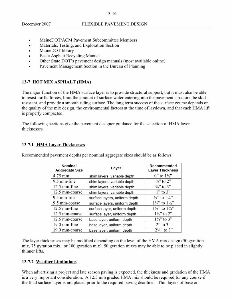
Hot mix asphalt (HMA), top 4 inches maximum 0.44 Hot mix asphalt below top 4 inches 0.34 Aggregate subbase course gravel (Type D/E) 0.09 Base Course Gravel (Type A or B, crushed or screened) 0.12 Dense-Graded Aggregate 0.14 Recycled Materials See Figure 13-4
13–6.5 Pavement Design Resources The following is a list of resources that the pavement designer can use to obtain pavement design information:
• AASHTO Guide for Design of Pavement Structures • Highway Program Support Unit
13-16 December 2007 FLEXIBLE PAVEMENT DESIGN
• MaineDOT/ACM Pavement Subcommittee Members • Materials, Testing, and Exploration Section • MaineDOT library • Basic Asphalt Recycling Manual • Other State DOT’s pavement design manuals (most available online) • Pavement Management Section in the Bureau of Planning
13-7 HOT MIX ASPHALT (HMA) The major function of the HMA surface layer is to provide structural support, but it must also be able to resist traffic forces, limit the amount of surface water entering into the pavement structure, be skid resistant, and provide a smooth riding surface. The long term success of the surface course depends on the quality of the mix design, the environmental factors at the time of laydown, and that each HMA lift is properly compacted. The following sections give the pavement designer guidance for the selection of HMA layer thicknesses. 13-7.1 HMA Layer Thicknesses Recommended pavement depths per nominal aggregate sizes should be as follows:
Nominal Aggregate Size Layer Recommended
Layer Thickness 4.75 mm shim layers, variable depth 0” to 1½” 9.5 mm-fine shim layers, variable depth ½” to 2” 12.5 mm-fine shim layers, variable depth ¾” to 3” 12.5 mm-coarse shim layers, variable depth 1” to 3” 9.5 mm-fine surface layers, uniform depth ¾” to 1¼” 9.5 mm-coarse surface layers, uniform depth 1¼” to 1½” 12.5 mm-fine surface layer, uniform depth 1½” to 1¾” 12.5 mm-coarse surface layer, uniform depth 1½” to 2” 12.5 mm-coarse base layer, uniform depth 1¾” to 3” 19.0 mm-fine base layer, uniform depth 2” to 3” 19.0 mm-coarse base layer, uniform depth 2¼” to 3”
The layer thicknesses may be modified depending on the level of the HMA mix design (50 gyration mix, 75 gyration mix, or 100 gyration mix). 50 gyration mixes may be able to be placed in slightly thinner lifts.
13-7.2 Weather Limitations When advertising a project and late season paving is expected, the thickness and gradation of the HMA is a very important consideration. A 12.5 mm graded HMA mix should be required for any course if the final surface layer is not placed prior to the required paving deadline. Thin layers of base or

13-17 December 2007 FLEXIBLE PAVEMENT DESIGN binder courses will cool off quickly in late season paving and may result in poor densities, poor surface texture and poor ride ability. A minimum of 2” of HMA should be placed over any recycled product if the project is to lay over the winter. See Standard Specification 401.06 Weather and Seasonal Limitations for complete details on HMA placement dates. 13-7.3 Smoothness To be used in future updates 13-8 SHOULDERS As defined by AASHTO, the shoulder is the portion of the roadway adjacent with the traveled way for accommodation of stopped vehicles for emergency use, and for lateral support of the subbase and surface courses. Paved shoulders also promote surface drainage, improve overall safety, and lower maintenance costs. Shoulders should be durable, compatible with the adjacent mainline pavement, and strong enough to handle heavy truck encroachment and maintenance traffic. 13-8.1 Shoulder Features Shoulder features such as width, break, cross-slope, and surface types are discussed in more detail in Volume One (National Standards) and Volume Two (State Standards) in the MaineDOT Highway Design Guide. Shoulder widths vary according to the roadway functional classification and traffic volumes. The shoulder width is typically the distance from the edge of the travel lane to the shoulder break. Refer to Section 6-1.02 and to the design tables in Chapters 7 and 11 in Volume One, and to Sections B and C in Volume Two of the MaineDOT Highway Design Guide for guidelines on standard shoulder widths. The shoulder break is the intersection of the shoulder slope and the embankment slope. The shoulder break typically begins at the edge of the shoulder pavement. Refer to Section 6-3.01 in Volume One, and to Section B in Volume Two of the MaineDOT Highway Design Guide for guidelines on shoulder breaks. The cross-slope is the slope of the pavement towards the roadside. An increase in the shoulder cross-slope provides quicker drain off of water from the travel lanes. The cross-slope break should be at the edge of the travel way and the typical shoulder cross-slope used for design is 4%. Refer to Sections 6-1.01, 6-1.02, and to the design tables in Chapters 7 and 11 in Volume One, and to Section B in Volume Two of the MaineDOT Highway Design Guide for guidelines on travel lane and shoulder cross-slopes. Shoulder surface types include paved and gravel surfaces. Refer to Section 6-1.02 and to the design tables in Chapters 7 and 11 in Volume One, and to Section C in Volume Two of the MaineDOT Highway Design Guide for guidelines on surface type selection.

13-18 December 2007 FLEXIBLE PAVEMENT DESIGN 13-8.2 Shoulder Design Full-depth shoulders are HMA shoulders that have the same cross-sectional thickness and material types as the adjacent travel lane and are designed to have the same design life as the mainline. Full depth shoulders are often an economical alternative if shoulder widths are 4’ wide or less. From a constructability standpoint, these shoulders can be paved concurrently with the mainline, resulting in some potential savings and ease of construction. If shoulder widths are greater than 4’, the recommended thickness of HMA is 3”. Partial-depth shoulders are HMA shoulders that have an HMA thickness less than the adjacent travel lane thickness. For new construction/reconstruction projects, the shoulder surface and intermediate HMA courses correspond to the travel lane HMA course thicknesses. To account for heavy truck wander, the full-depth section should be extended 24 inches into the shoulder. Some shoulders are subjected to above normal traffic use, such as across from commercial entrances, the inside of curves, including ramps, in intersections, or opposite the leg of “T” intersections. To prevent the HMA on the shoulders from deteriorating prematurely, these locations should have full-depth shoulders even if the traffic information warrants partial-depth shoulders. Full-depth shoulders should be used for intersections with safety widenings and should begin 20 feet before the Point of Curve (P.C.) and terminate 10 feet beyond the Point of Tangent (P.T.). When safety widenings are not provided, full-depth shoulders should be used 50 feet in advance of the P.C. and end 10 feet beyond the P.T. Where right-turning traffic may illegally use the shoulder as a turn lane, full-depth shoulders should begin 165 feet in advance of the P.C. Where large vehicles will have trouble negotiating curves and corners without encroaching onto the shoulders, the designer should use truck templates to determine whether full-depth shoulders should extend beyond the limits given above. 13-9 CONTRACT DOCUMENTS Once the pavement design has been finalized and approved, a HMA pavement Special Provision (Section 403) must be generated for the contract documents. Since each project may have differing material and lift thickness requirements, a Special Provision must be generated for each project that addresses the project specific requirements for the Hot Mix Asphalt (HMA) used in the project. Special Provisions override the Standard Specifications, so it is extremely important that the 403 Special Provision accurately reflect the materials, quantities, and construction requirements of the project. Once the pavement design has been approved and the HMA quantities have been determined, this information should be submitted to the Support Section to generate Special Provision-Section 403-HOT MIX ASPHALT. The Special Provision 403 request form outlines the type of materials to be utilized in the contract, the lift thicknesses of each type of material, quantity breakdown of each material between travel ways, widenings, ramps, shoulders, or other areas of material placement. An example of this request form is shown in Figure 13-5. This request form is located at \\Dot0dta1fsaug01\$com-cons\~O D G the New Millennium\403 Request Forms.

December 2007 FLEXIBLE PAVEMENT DESIGN
APPENDIX

December 2007 FLEXIBLE PAVEMENT DESIGN
FIGURE 13-1


December 2007 FLEXIBLE PAVEMENT DESIGN
FIGURE 13-3
December 2007 FLEXIBLE PAVEMENT DESIGN
FIGURE 13-4
Structural Coefficient Guidance The structural coefficients for these recycled treatments vary depending on the existing conditions of the roadway. The designer must use engineering judgment to determine the proper structural coefficient to use for a given application, within the assigned range. The following three things need to be considered:
1) Type of mix being recycled. If the existing HMA layers consist of designed mixes with good quality aggregates then a higher structural coefficient can be used. Conversely, if the existing HMA layer consists primarily of sand mix (Maintenance Mulch) then a lower number should be considered.
2) Underlying Material. If the underlying material is new, or the existing material meets
current Department standards, then a higher structural number can be assumed. If the underlying material is of a lower quality, then a lower structural number should be considered.
3) Drainage characteristics: If you have a well drained pavement structure, you can assume a
higher structural number (i.e. under drain or adequate depth ditches). If you do not have adequate drainage, or there is a high probability of saturated subgrade soils being present, a lower number should be considered.

December 2007 FLEXIBLE PAVEMENT DESIGN
FIGURE 13-5 To: Brian Luce; Bituminous Special Provisions ([email protected]) Note: Please include Typical Sections for Bituminous Items. From: Bureau, Office or Division: Subject: Pavement Design Information, (Special Provision, Sec. 403) for the following project:
Project #: Town(s)/City(s) Pin #: Route #(s) Project Level Traffic Data Level: 80-kN ESALs Over 20 Years (18 kip @ 2.5 x 365 x 20 yr = ESAL’s) Approx. Mg or Tonnage Quantities for Item - 403.208 12.5mm Surface Mix Approx. Mg or Tonnage Quantities for Item - 403.207 19.0mm Base Mix Approx. Mg or Tonnage Quantities for Item - 403.211 9.5mm Shim and Leveling Mix
Mainline Overlay Shoulders Approach Roads Shim (Leveling mix) Paved Surface Course Paved Surface Course: Paved Surface Course: YES NO Depth: _____ Depth: _____ Depth: _____ Variable Depth ( ) Type Mix :______ Type Mix: ______ Type Mix: ______ ½” minimum ( ) Quantity: Quantity: Quantity: Other
Overlay ( )orGravel ( ) Paved Base Course: Paved Base Course: Paved Base Course: Depth: _____ Depth: _____ Depth: _____ Type Mix: ______ Type Mix: ______ Type Mix: ______ Quantity : Quantity: Quantity:
Full Construction Recycled Pavements (C.I.P; R.A.P) Paved Shoulders Paved Surface Course: Paved Surface Course: Paved Surface Course: Depth: _____ Depth: _____ Depth: _____ Type Mix: ______ Type Mix: ______ Type Mix: ______ Quantity: Quantity: Quantity: Paved Base Course: Paved Base Course: Paved Base Course: Depth: _____ Depth: _____ Depth: _____ Type Mix: ______ Type Mix: ______ TypeMix: Quantity: Quantity: Quantity:
Please check Y or N if the following apply: Is this project to take more than one construction season? YES ( ) NO ( )
YES NO DEPTH Sidewalks ( ) ( ) ______ Will this project require the use of note # 20 Drives ( ) ( ) ______ Open centerline joint on ¾ inch (20mm) surface course YES ( ) Islands ( ) ( ) ______ NO ( ) Miscellaneous ( ) ( ) ______ Will this project require the use of note # 20 Quantity: _ Open centerline joint on shim. YES ( )
NO ( ) Is this Project a Ride Quality Candidate ? YES ( ) NO ( )
Comments:_