chapter motherboards 5 - cengage.com · motherboards •about the different types of motherboards...
TRANSCRIPT
175
Motherboards
• About the different typesof motherboardsand how toselect one
• How to supportand configure amotherboard
• How to install orreplace a mother-board
• How to trou-bleshoot a motherboardand processor
In this chapter,you will learn:
CHAPTER
5
In the last chapter, we looked at the two most important compo-nents on the motherboard: the processor and chipset. In this chap-
ter, we turn our attention to the motherboard itself. You’ll learnabout the buses and expansion slots on the motherboard and how toconfigure these and other components on the board. The mother-board is considered a field replaceable unit. So, in this chapter, you’lllearn to troubleshoot problems with the motherboard and how toinstall and replace one.
SELECTING A MOTHERBOARD
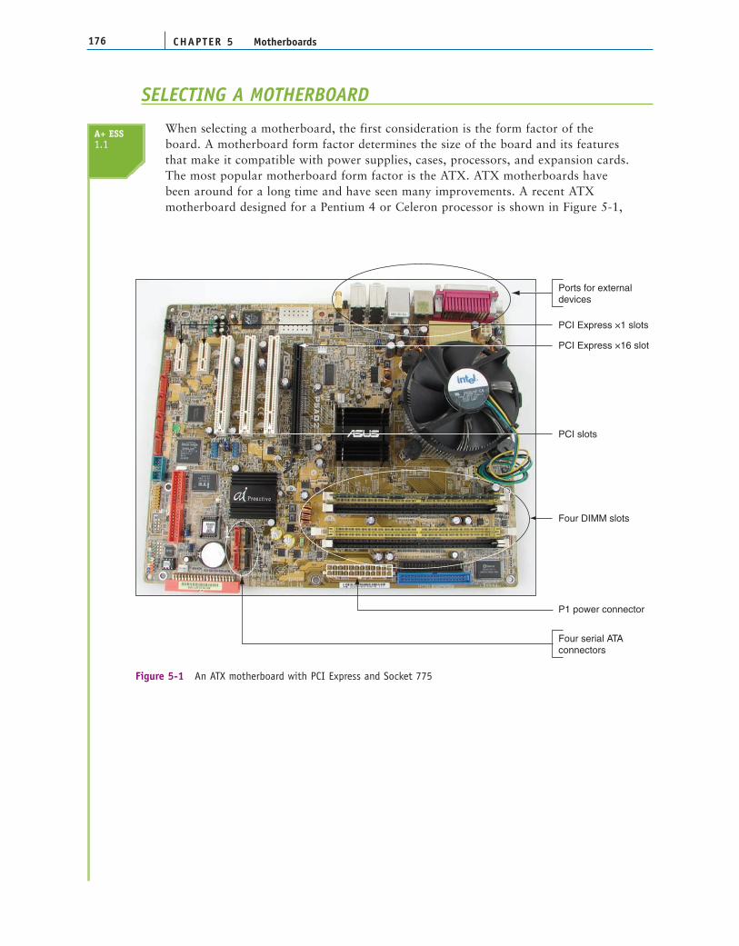
When selecting a motherboard, the first consideration is the form factor of theboard. A motherboard form factor determines the size of the board and its featuresthat make it compatible with power supplies, cases, processors, and expansion cards.The most popular motherboard form factor is the ATX. ATX motherboards havebeen around for a long time and have seen many improvements. A recent ATXmotherboard designed for a Pentium 4 or Celeron processor is shown in Figure 5-1,
CHAPTER 5176 Motherboards
Four serial ATA connectors
Four DIMM slots
P1 power connector
PCI Express ×1 slots
Ports for external devices
PCI Express ×16 slot
PCI slots
Figure 5-1 An ATX motherboard with PCI Express and Socket 775
A+ ESS1.1
5
177Selecting a Motherboard
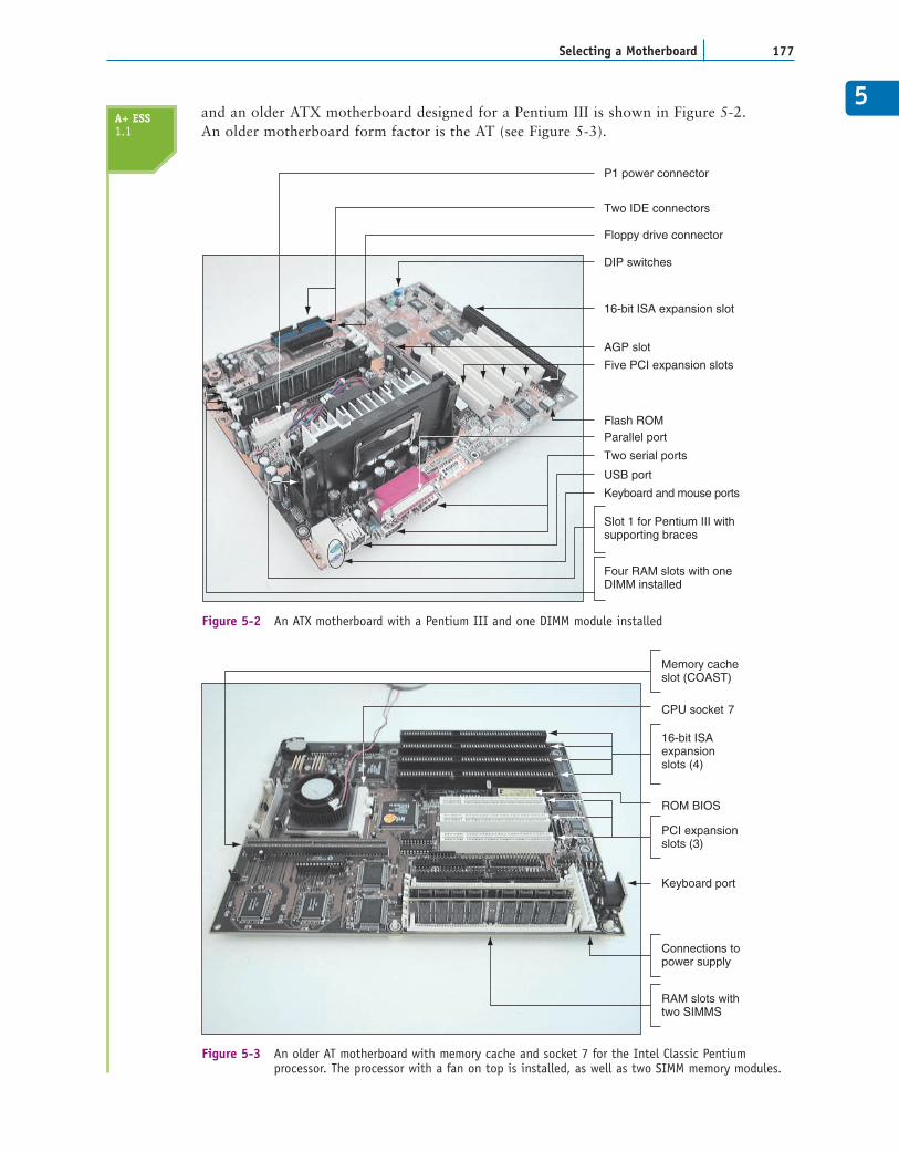
and an older ATX motherboard designed for a Pentium III is shown in Figure 5-2.An older motherboard form factor is the AT (see Figure 5-3).
P1 power connector
Slot 1 for Pentium III withsupporting braces
Two IDE connectors
Floppy drive connector
DIP switches
Flash ROM
16-bit ISA expansion slot
Five PCI expansion slots
AGP slot
Parallel port
Two serial ports
USB port
Keyboard and mouse ports
Four RAM slots with oneDIMM installed
Figure 5-2 An ATX motherboard with a Pentium III and one DIMM module installed
CPU socket 7
RAM slots withtwo SIMMS
ROM BIOS
Connections topower supply
16-bit ISAexpansionslots (4)
PCI expansionslots (3)
Memory cacheslot (COAST)
Keyboard port
Figure 5-3 An older AT motherboard with memory cache and socket 7 for the Intel Classic Pentium processor. The processor with a fan on top is installed, as well as two SIMM memory modules.
A+ ESS1.1
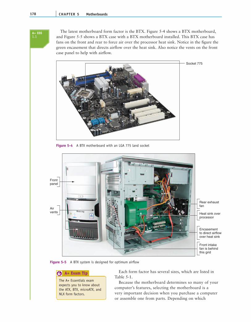
The latest motherboard form factor is the BTX. Figure 5-4 shows a BTX motherboard,and Figure 5-5 shows a BTX case with a BTX motherboard installed. This BTX case hasfans on the front and rear to force air over the processor heat sink. Notice in the figure thegreen encasement that directs airflow over the heat sink. Also notice the vents on the frontcase panel to help with airflow.
CHAPTER 5178 Motherboards
Socket 775
Figure 5-4 A BTX motherboard with an LGA 775 land socket
Heat sink overprocessor
Rear exhaustfan
Encasementto direct airflowover heat sink
Front intakefan is behindthis grid
Frontpanel
Airvents
Figure 5-5 A BTX system is designed for optimum airflow
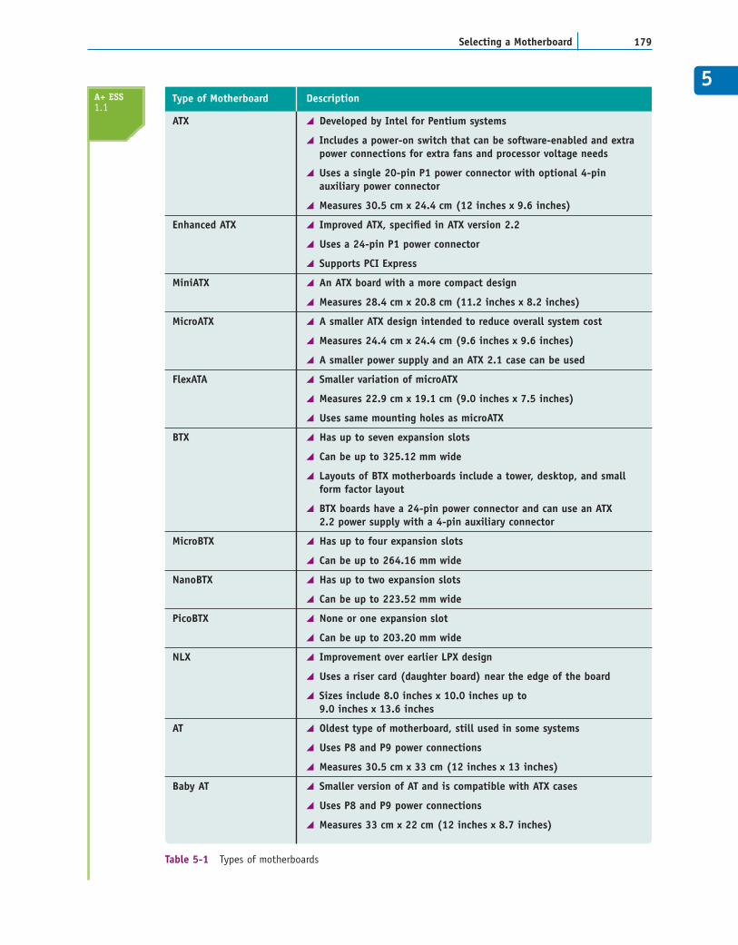
Each form factor has several sizes, which are listed inTable 5-1.
Because the motherboard determines so many of yourcomputer’s features, selecting the motherboard is avery important decision when you purchase a computeror assemble one from parts. Depending on which
A+ ESS1.1
The A+ Essentials examexpects you to know aboutthe ATX, BTX, microATX, andNLX form factors.
A+ Exam Tip6
5
179Selecting a Motherboard
ATX Developed by Intel for Pentium systems
Includes a power-on switch that can be software-enabled and extra power connections for extra fans and processor voltage needs
Uses a single 20-pin P1 power connector with optional 4-pin auxiliary power connector
Measures 30.5 cm x 24.4 cm (12 inches x 9.6 inches)
Enhanced ATX Improved ATX, specified in ATX version 2.2
Uses a 24-pin P1 power connector
Supports PCI Express
MiniATX An ATX board with a more compact design
Measures 28.4 cm x 20.8 cm (11.2 inches x 8.2 inches)
MicroATX A smaller ATX design intended to reduce overall system cost
Measures 24.4 cm x 24.4 cm (9.6 inches x 9.6 inches)
A smaller power supply and an ATX 2.1 case can be used
FlexATA Smaller variation of microATX
Measures 22.9 cm x 19.1 cm (9.0 inches x 7.5 inches)
Uses same mounting holes as microATX
BTX Has up to seven expansion slots
Can be up to 325.12 mm wide
Layouts of BTX motherboards include a tower, desktop, and small form factor layout
BTX boards have a 24-pin power connector and can use an ATX2.2 power supply with a 4-pin auxiliary connector
MicroBTX Has up to four expansion slots
Can be up to 264.16 mm wide
NanoBTX Has up to two expansion slots
Can be up to 223.52 mm wide
PicoBTX None or one expansion slot
Can be up to 203.20 mm wide
NLX Improvement over earlier LPX design
Uses a riser card (daughter board) near the edge of the board
Sizes include 8.0 inches x 10.0 inches up to 9.0 inches x 13.6 inches
AT Oldest type of motherboard, still used in some systems
Uses P8 and P9 power connections
Measures 30.5 cm x 33 cm (12 inches x 13 inches)
Baby AT Smaller version of AT and is compatible with ATX cases
Uses P8 and P9 power connections
Measures 33 cm x 22 cm (12 inches x 8.7 inches)
Type of Motherboard Description
Table 5-1 Types of motherboards
A+ ESS1.1
applications and peripheral devices you plan to use with the computer, you can take oneof three approaches to selecting a motherboard. The first approach is to select the boardthat provides the most room for expansion, so you can upgrade and exchange compo-nents and add devices easily. A second approach is to select the board that best suits theneeds of the computer’s current configuration, knowing that when you need to upgrade,you will likely switch to new technology and a new motherboard. The third approachis to select a motherboard that meets your present needs with moderate room forexpansion.
Ask the following questions when selecting a motherboard:
What form factor does the motherboard use?Does the motherboard support the number and type of processor you plan to use (forexample, Socket LGA 775 for the Intel Pentium 4 up to 3.3 GHz)?What are the supported frequencies of the system bus (for example, 1066/800/533 MHz)?What chipset does the board use?What type of memory does the board support (DDR or DDR2), and how muchmemory can the board hold?What type and how many expansion slots are on the board (for example, PCI,PCI Express, and AGP)?What hard drive controllers and connectors are on the board (for example, IDE, serialATA, RAID, and SCSI)?What are the embedded devices on the board and what internal slots or connec-tions does the board have? (For example, the board might provide a network port,wireless antenna port, FireWire port, two or more USB ports, modem port, and soforth.)What type of BIOS does the motherboard use?Does the board fit the case you plan to use?What is the warranty on the board?How extensive and user-friendly is the documentation?How much support does the manufacturer supply for the board?
Sometimes a motherboard contains a component more commonly offered as a separatedevice. A component on the board is called an embedded component or an on-board
component. One example is support for video. The videoport might be on the motherboard or might require avideo card. The cost of a motherboard with an embeddedcomponent is usually less than the combined cost of amotherboard with no embedded component and anexpansion card. If you plan to expand, be cautious aboutchoosing a proprietary board that has many embeddedcomponents. Often such boards do not easily accept add-on devices from other manufacturers. For example, if youplan to add a more powerful video card, you might notwant to choose a motherboard that contains an embed-ded video controller. Even though you can often use ajumper or CMOS setup to disable the proprietary videocontroller, there is little advantage to paying the extramoney for it.
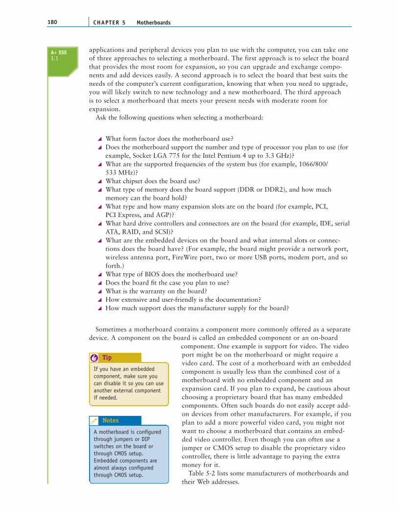
Table 5-2 lists some manufacturers of motherboards andtheir Web addresses.
CHAPTER 5180 Motherboards
A+ ESS1.1
If you have an embeddedcomponent, make sure youcan disable it so you can useanother external componentif needed.
Tip6
A motherboard is configuredthrough jumpers or DIPswitches on the board orthrough CMOS setup.Embedded components arealmost always configuredthrough CMOS setup.
Notes
5
CONFIGURING AND SUPPORTING A MOTHERBOARD
The components on the motherboard that you must know how to configure and support arethe expansion slots and other internal and external connectors. In this section, you’ll learnabout the expansion slots and the buses that support them, and then you’ll learn how toconfigure these expansion slots and other components and connectors on the board. In laterchapters, you’ll learn more about the other connectors on the board, including memorymodule slots, and the various drive, USB, FireWire, serial, and parallel connectors.
BUSES AND EXPANSION SLOTSAs cities grow, so do their transportation systems. Small villages have only simple, two-laneroads, but large cities have one-way streets, four-lane roads, and major freeways, each withtheir own set of traffic laws, including minimum and maximum speeds, access methods, andprotocols. As microcomputer systems have evolved, so too have their “transportation” sys-tems. The earliest PC had only a single simple bus. Today’s PCs have four or five buses, eachwith different speeds, access methods, and protocols. As you have seen in previous chapters,backward compatibility dictates that older buses be supported on a motherboard, evenwhen faster, better buses exist. All this makes for a maze of buses on a motherboard.
WHAT A BUS DOESLook on the bottom of the motherboard, and you see a maze of circuits that make up a bus.These embedded wires carry four kinds of cargo:
Electrical power. Chips on the motherboard require power to function. These chipstap into a bus’s power lines and draw what they need.
181Configuring and Supporting a Motherboard
Abit www.abit.com.tw
American Megatrends, Inc. (AMI) www.megatrends.com or www.ami.com
ASUS www.asus.com
BIOSTAR Group www.biostar.com.tw
Dell www.dell.com
First International Computer www.fica.comof America, Inc.
Gateway www.gateway.com
Gigabyte Technology Co., Ltd. us.giga-byte.com
IBM www.ibm.com
Intel Corporation www.intel.com
Iwill Corporation www.iwill.net
MicroStar International www.msicomputer.com
Motherboards.com www.motherboards.com
Supermicro Computer, Inc. www.supermicro.com
Tyan Computer Corporation www.tyan.com
Manufacturer Web Address
Table 5-2 Major manufacturers of motherboards
A+ ESS1.1
Control signals. Some wires on a bus carry control signals that coordinate all theactivity.Memory addresses. Components pass memory addresses to one another, tellingeach other where to access data or instructions. The number of wires that make upthe memory address lines of the bus determines how many bits can be used for amemory address. The number of wires thus limits the amount of memory the buscan address.Data. Data passes over a bus in a group of wires, just as memory addresses do. Thenumber of lines in the bus used to pass data determines how much data can be passedin parallel at one time. The number of lines depends on the type of processor anddetermines the number of bits in the data path. (Remember that a data path is the partof the bus on which the data is placed; it can be 8, 16, 32, 64, or more bits wide.)
BUS EVOLUTIONJust as a city’s road system improves to increase the speed and number of lanes of traffic,buses have evolved around similar issues, data path and speed. Cars on a freeway generallytravel at a continuous speed, but traffic on a computer’s processor or bus is digital (on andoff), rather than analog (continuous). The system clock keeps the beat for components. If acomponent on the motherboard works by the beat, or clock cycle, then it is synchronized,or in sync, with the processor. For example, the back-side bus of the Pentium works at halfthe speed of the processor. This means that the processor does something on each clockcycle, but the back-side bus is doing something on every other clock cycle.
Some components don’t attempt to keep in sync with the processor, even to work at one-half or one-third of clock cycles. These components work asynchronously with the proces-sor. They might work at a rate determined by the system clock or by another crystal on oroff the motherboard. Either way, the frequency is much slower than the processor’s and notin sync with it. If the processor requests something from one of these devices and the deviceis not ready, the device issues a wait state, which is a command to the processor to wait forslower devices to catch up.
The first expansion slots on early PCs were Industry Standard Architecture (ISA) slots.These slots had an 8-bit data path and ran at 4.77 MHz. Later, the 16-bit ISA slots wereadded that ran at 8.33 MHz. The 16-bit slots were backward-compatible with 8-bit cards;an 8-bit card used only a portion of the 16-bit slot. These 16-bit ISA slots are still in use onsome older motherboards. To know how to support these legacy slots and cards, seeAppendix C, “Supporting Legacy Devices.”
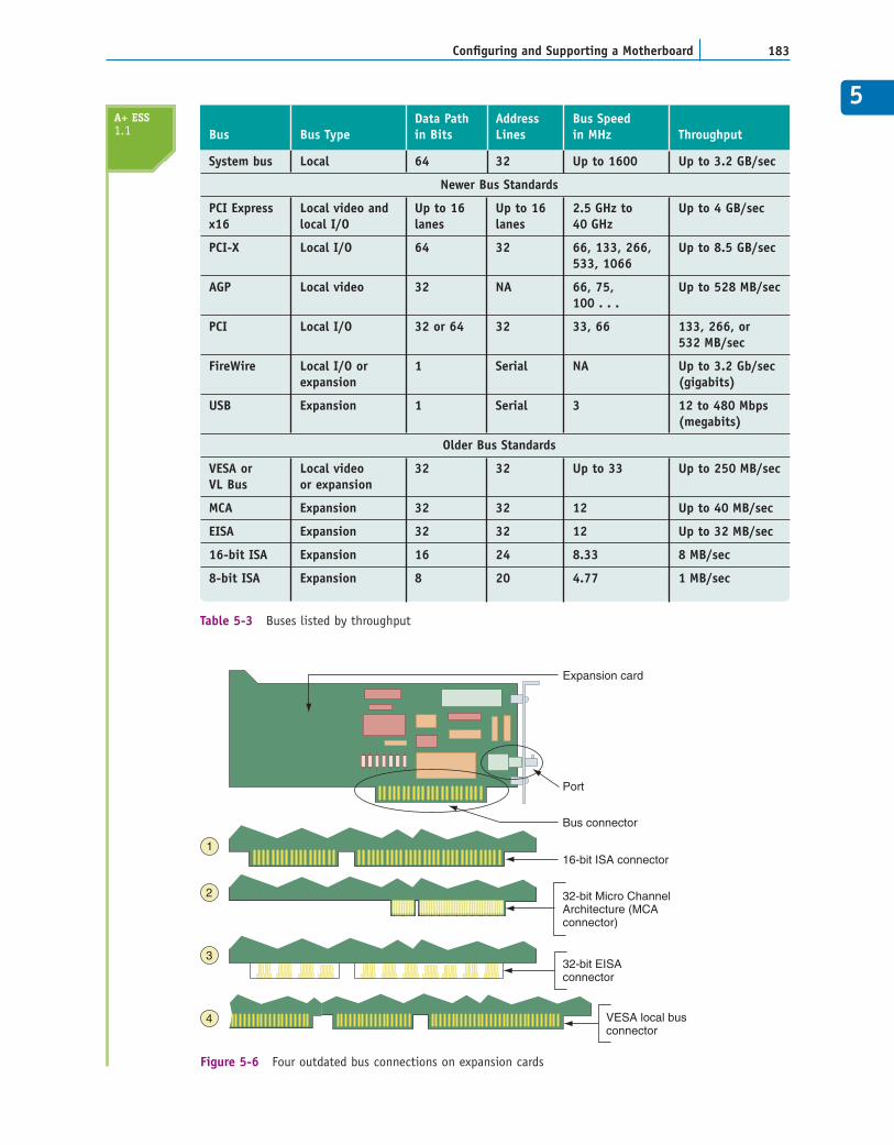
Table 5-3 lists the various buses, in order of throughput speed from fastest to slowest.The evolution of buses includes earlier proprietary designs and the outdated ISA, EISA,MCA, and VESA buses. In Figure 5-6, you can see the shape of each of these bus connec-tors. Current buses include the USB bus, the IEEE 1394 (FireWire) bus, the original PCI bus,the AGP bus (for video only), the PCI-X, and the newer PCI Express bus. The USB,FireWire, and AGP buses are discussed in Chapter 8.
Looking at the second column of Table 5-3, you can see that a bus is called an expansionbus, local bus, local I/O bus, or local video bus. A bus that does not run in sync with thesystem clock is called an expansion bus and always connects to the slow end of the chipset,the South Bridge. Most buses today are local buses, meaning they run in sync with the sys-tem clock. If a local bus connects to the slower I/O controller hub or South Bridge of thechipset, it is called a local I/O bus. Because the video card needs to run at a faster rate thanother expansion cards, this one slot always connects to the faster end of the chipset, theNorth Bridge. This video slot can be either an AGP slot or a PCI Express x16 slot, and thebus is called a local video bus. Several PCI buses are covered next.
CHAPTER 5182 Motherboards
A+ ESS1.1
5
183Configuring and Supporting a Motherboard
System bus Local 64 32 Up to 1600 Up to 3.2 GB/sec
Newer Bus Standards
PCI Express Local video and Up to 16 Up to 16 2.5 GHz to Up to 4 GB/secx16 local I/O lanes lanes 40 GHz
PCI-X Local I/O 64 32 66, 133, 266, Up to 8.5 GB/sec533, 1066
AGP Local video 32 NA 66, 75, Up to 528 MB/sec100 . . .
PCI Local I/O 32 or 64 32 33, 66 133, 266, or 532 MB/sec
FireWire Local I/O or 1 Serial NA Up to 3.2 Gb/sec expansion (gigabits)
USB Expansion 1 Serial 3 12 to 480 Mbps (megabits)
Older Bus Standards
VESA or Local video 32 32 Up to 33 Up to 250 MB/secVL Bus or expansion
MCA Expansion 32 32 12 Up to 40 MB/sec
EISA Expansion 32 32 12 Up to 32 MB/sec
16-bit ISA Expansion 16 24 8.33 8 MB/sec
8-bit ISA Expansion 8 20 4.77 1 MB/sec
Data Path Address Bus SpeedBus Bus Type in Bits Lines in MHz Throughput
Table 5-3 Buses listed by throughput
Expansion card
Bus connector
32-bit Micro ChannelArchitecture (MCAconnector)
16-bit ISA connector
32-bit EISAconnector
VESA local busconnector
Port
1
2
3
4
Figure 5-6 Four outdated bus connections on expansion cards
A+ ESS1.1
THE PCI BUSESThe original PCI bus was introduced by Intel in 1991, intended to replace the 16-bit ISAbus. For many years, most motherboards had both ISA and PCI slots. You can see an exam-ple of one of these boards in Chapter 1, Figure 1-12, which has three black 16-bit ISA slots,four white PCI slots, and an early version of an AGP slot. PCI has been improved severaltimes; there are currently three major categories and within each category, several variationsof PCI. In the following sections, we discuss each category in turn.
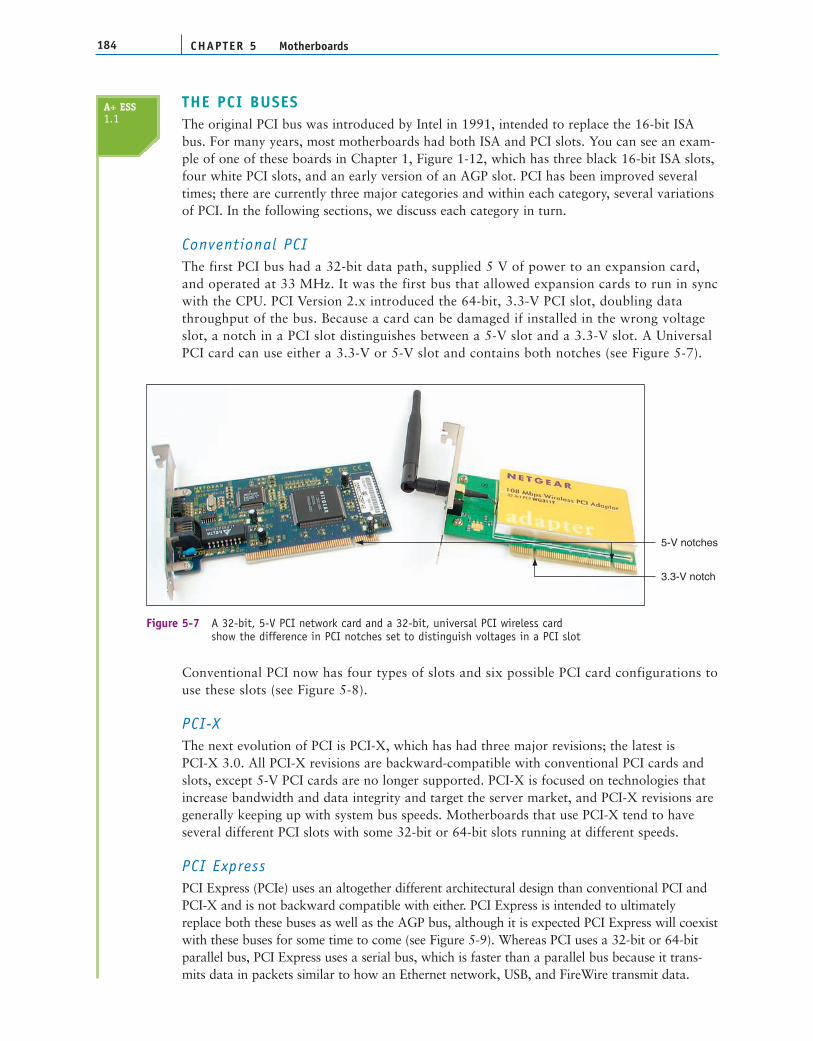
Conventional PCIThe first PCI bus had a 32-bit data path, supplied 5 V of power to an expansion card,and operated at 33 MHz. It was the first bus that allowed expansion cards to run in syncwith the CPU. PCI Version 2.x introduced the 64-bit, 3.3-V PCI slot, doubling datathroughput of the bus. Because a card can be damaged if installed in the wrong voltageslot, a notch in a PCI slot distinguishes between a 5-V slot and a 3.3-V slot. A UniversalPCI card can use either a 3.3-V or 5-V slot and contains both notches (see Figure 5-7).
CHAPTER 5184 Motherboards
5-V notches
3.3-V notch
Figure 5-7 A 32-bit, 5-V PCI network card and a 32-bit, universal PCI wireless card show the difference in PCI notches set to distinguish voltages in a PCI slot
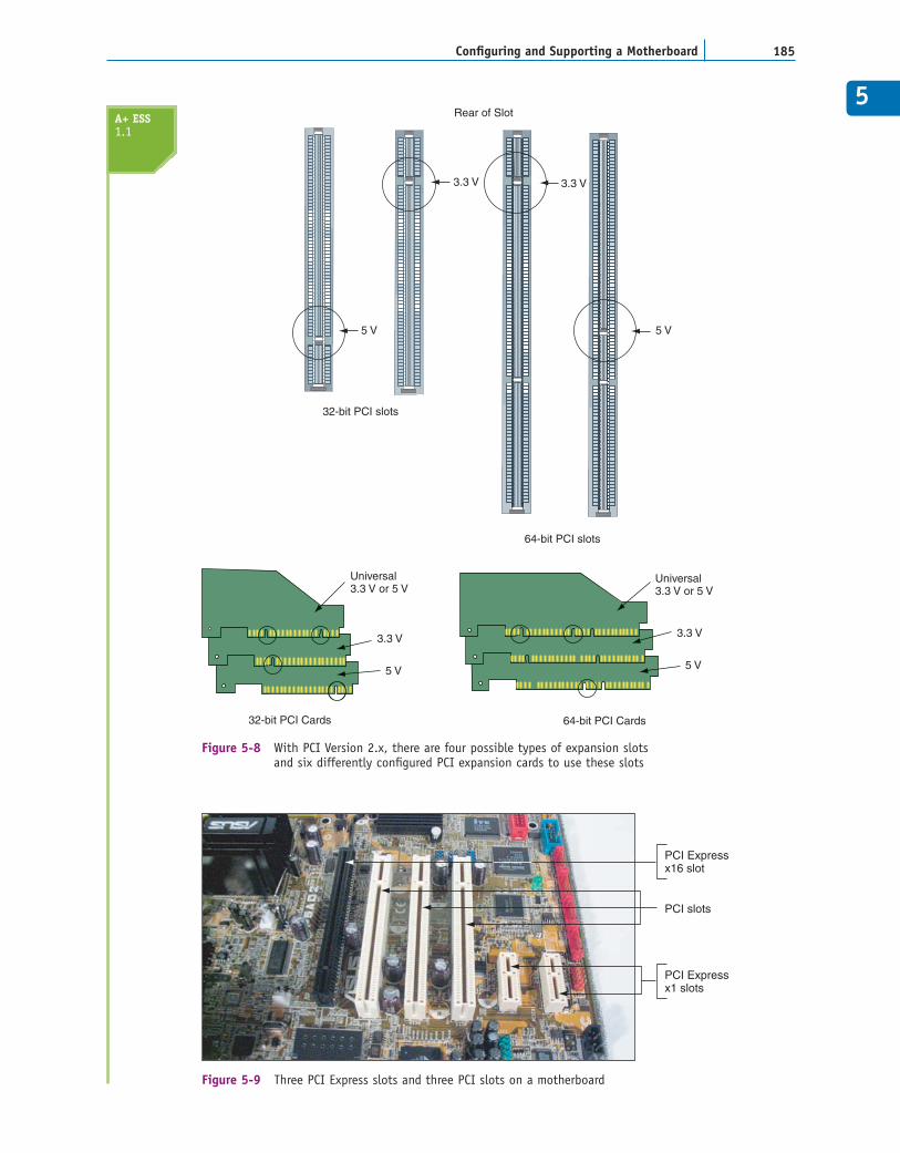
Conventional PCI now has four types of slots and six possible PCI card configurations touse these slots (see Figure 5-8).
PCI-XThe next evolution of PCI is PCI-X, which has had three major revisions; the latest is PCI-X 3.0. All PCI-X revisions are backward-compatible with conventional PCI cards andslots, except 5-V PCI cards are no longer supported. PCI-X is focused on technologies thatincrease bandwidth and data integrity and target the server market, and PCI-X revisions aregenerally keeping up with system bus speeds. Motherboards that use PCI-X tend to haveseveral different PCI slots with some 32-bit or 64-bit slots running at different speeds.
PCI ExpressPCI Express (PCIe) uses an altogether different architectural design than conventional PCI andPCI-X and is not backward compatible with either. PCI Express is intended to ultimatelyreplace both these buses as well as the AGP bus, although it is expected PCI Express will coexistwith these buses for some time to come (see Figure 5-9). Whereas PCI uses a 32-bit or 64-bitparallel bus, PCI Express uses a serial bus, which is faster than a parallel bus because it trans-mits data in packets similar to how an Ethernet network, USB, and FireWire transmit data.
A+ ESS1.1
5
185Configuring and Supporting a Motherboard
Rear of Slot
5 V 5 V
3.3 V 3.3 V
32-bit PCI slots
64-bit PCI slots
64-bit PCI Cards32-bit PCI Cards
Universal3.3 V or 5 V
Universal3.3 V or 5 V
3.3 V3.3 V
5 V5 V
Figure 5-8 With PCI Version 2.x, there are four possible types of expansion slots and six differently configured PCI expansion cards to use these slots
PCI Expressx16 slot
PCI slots
PCI Expressx1 slots
Figure 5-9 Three PCI Express slots and three PCI slots on a motherboard
A+ ESS1.1
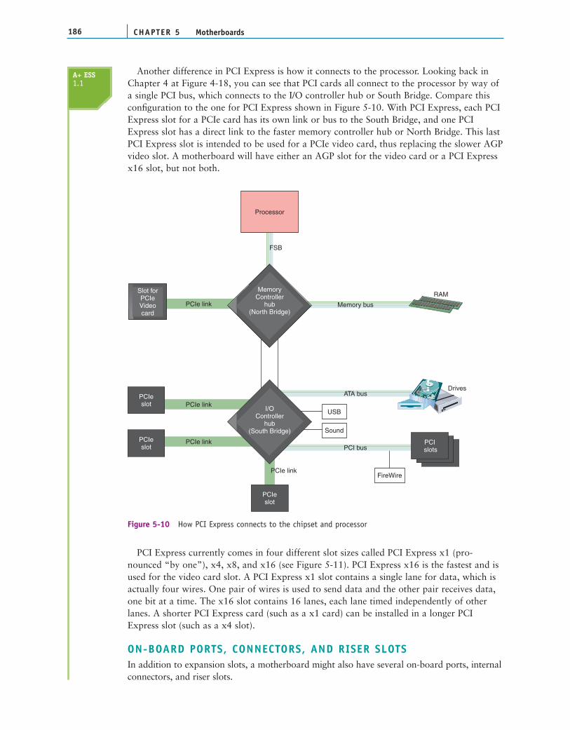
Another difference in PCI Express is how it connects to the processor. Looking back inChapter 4 at Figure 4-18, you can see that PCI cards all connect to the processor by way ofa single PCI bus, which connects to the I/O controller hub or South Bridge. Compare thisconfiguration to the one for PCI Express shown in Figure 5-10. With PCI Express, each PCIExpress slot for a PCIe card has its own link or bus to the South Bridge, and one PCIExpress slot has a direct link to the faster memory controller hub or North Bridge. This lastPCI Express slot is intended to be used for a PCIe video card, thus replacing the slower AGPvideo slot. A motherboard will have either an AGP slot for the video card or a PCI Expressx16 slot, but not both.
CHAPTER 5186 Motherboards
PC I slots
PC I slots
PCIe link
PCIe link
Processor
PCIeslot
Slot forPCIeVideocard
MemoryController
hub(North Bridge)
I/OController
hub(South Bridge)
PCIeslot
PCIeslot
PCI slots
PCIe link
PCIe link
Memory bus
ATA bus
PCI bus
Drives
USB
Sound
FireWire
FSB
RAM
Figure 5-10 How PCI Express connects to the chipset and processor
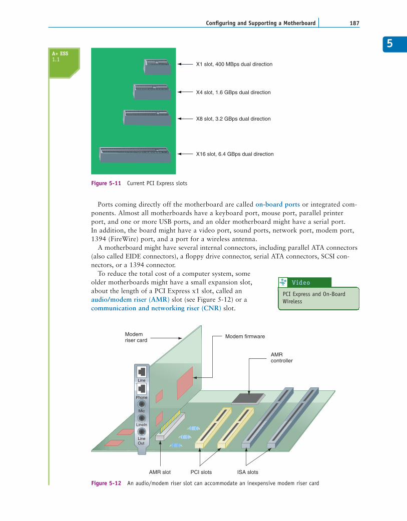
PCI Express currently comes in four different slot sizes called PCI Express x1 (pro-nounced “by one”), x4, x8, and x16 (see Figure 5-11). PCI Express x16 is the fastest and isused for the video card slot. A PCI Express x1 slot contains a single lane for data, which isactually four wires. One pair of wires is used to send data and the other pair receives data,one bit at a time. The x16 slot contains 16 lanes, each lane timed independently of otherlanes. A shorter PCI Express card (such as a x1 card) can be installed in a longer PCIExpress slot (such as a x4 slot).
ON-BOARD PORTS, CONNECTORS, AND RISER SLOTSIn addition to expansion slots, a motherboard might also have several on-board ports, internalconnectors, and riser slots.
A+ ESS1.1
5
187Configuring and Supporting a Motherboard
X1 slot, 400 MBps dual direction
X4 slot, 1.6 GBps dual direction
X8 slot, 3.2 GBps dual direction
X16 slot, 6.4 GBps dual direction
Figure 5-11 Current PCI Express slots
Ports coming directly off the motherboard are called on-board ports or integrated com-ponents. Almost all motherboards have a keyboard port, mouse port, parallel printerport, and one or more USB ports, and an older motherboard might have a serial port.In addition, the board might have a video port, sound ports, network port, modem port,1394 (FireWire) port, and a port for a wireless antenna.
A motherboard might have several internal connectors, including parallel ATA connectors(also called EIDE connectors), a floppy drive connector, serial ATA connectors, SCSI con-nectors, or a 1394 connector.
To reduce the total cost of a computer system, someolder motherboards might have a small expansion slot,about the length of a PCI Express x1 slot, called anaudio/modem riser (AMR) slot (see Figure 5-12) or acommunication and networking riser (CNR) slot.
AMRcontroller
AMR slot PCI slots ISA slots
Modemriser card
Modem firmware
Line
LineIn
LineOut
Mic
Phone
Figure 5-12 An audio/modem riser slot can accommodate an inexpensive modem riser card
A+ ESS1.1
PCI Express and On-BoardWireless
Video 8
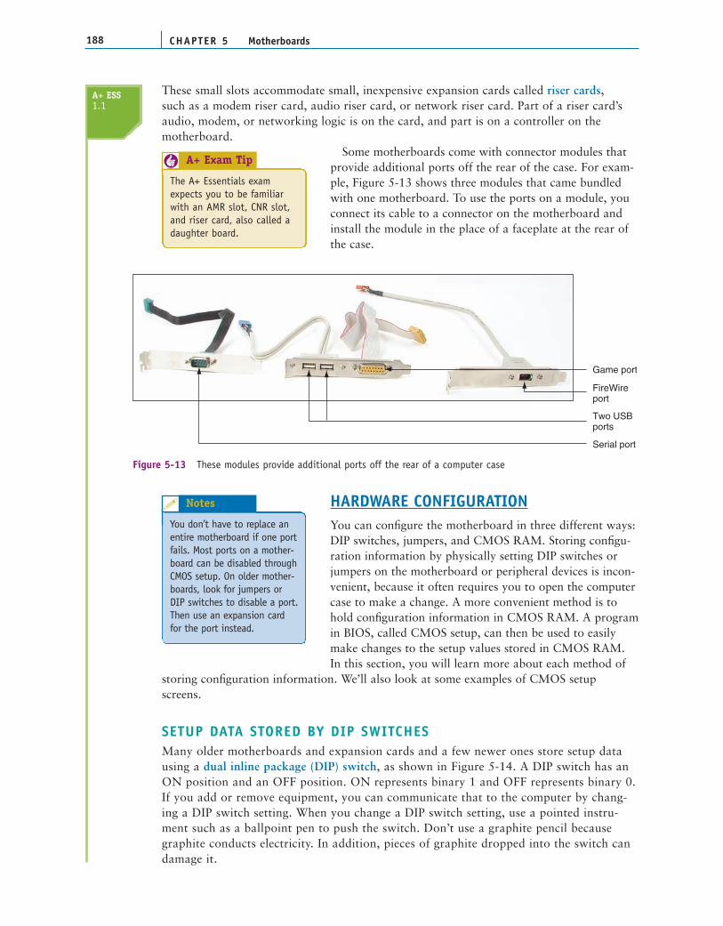
These small slots accommodate small, inexpensive expansion cards called riser cards,such as a modem riser card, audio riser card, or network riser card. Part of a riser card’saudio, modem, or networking logic is on the card, and part is on a controller on themotherboard.
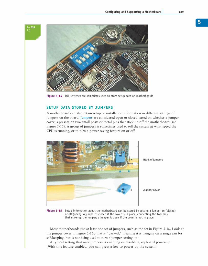
Some motherboards come with connector modules thatprovide additional ports off the rear of the case. For exam-ple, Figure 5-13 shows three modules that came bundledwith one motherboard. To use the ports on a module, youconnect its cable to a connector on the motherboard andinstall the module in the place of a faceplate at the rear ofthe case.
CHAPTER 5188 Motherboards
Serial port
Two USBports
FireWireport
Game port
Figure 5-13 These modules provide additional ports off the rear of a computer case
HARDWARE CONFIGURATIONYou can configure the motherboard in three different ways:DIP switches, jumpers, and CMOS RAM. Storing configu-ration information by physically setting DIP switches orjumpers on the motherboard or peripheral devices is incon-venient, because it often requires you to open the computercase to make a change. A more convenient method is tohold configuration information in CMOS RAM. A programin BIOS, called CMOS setup, can then be used to easilymake changes to the setup values stored in CMOS RAM.In this section, you will learn more about each method of
storing configuration information. We’ll also look at some examples of CMOS setupscreens.
SETUP DATA STORED BY DIP SWITCHESMany older motherboards and expansion cards and a few newer ones store setup datausing a dual inline package (DIP) switch, as shown in Figure 5-14. A DIP switch has anON position and an OFF position. ON represents binary 1 and OFF represents binary 0.If you add or remove equipment, you can communicate that to the computer by chang-ing a DIP switch setting. When you change a DIP switch setting, use a pointed instru-ment such as a ballpoint pen to push the switch. Don’t use a graphite pencil becausegraphite conducts electricity. In addition, pieces of graphite dropped into the switch candamage it.
A+ ESS1.1
The A+ Essentials examexpects you to be familiarwith an AMR slot, CNR slot,and riser card, also called adaughter board.
A+ Exam Tip6
You don’t have to replace anentire motherboard if one portfails. Most ports on a mother-board can be disabled throughCMOS setup. On older mother-boards, look for jumpers orDIP switches to disable a port.Then use an expansion cardfor the port instead.
Notes
5
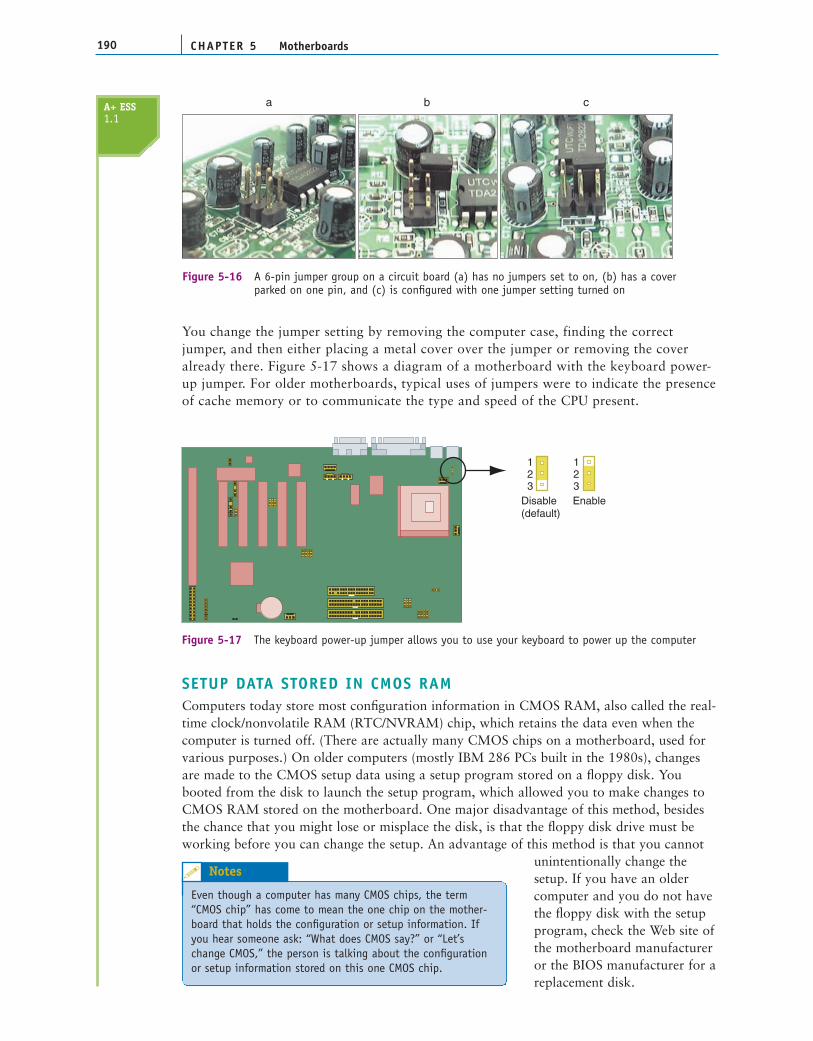
SETUP DATA STORED BY JUMPERSA motherboard can also retain setup or installation information in different settings ofjumpers on the board. Jumpers are considered open or closed based on whether a jumpercover is present on two small posts or metal pins that stick up off the motherboard (seeFigure 5-15). A group of jumpers is sometimes used to tell the system at what speed theCPU is running, or to turn a power-saving feature on or off.
189Configuring and Supporting a Motherboard
Figure 5-14 DIP switches are sometimes used to store setup data on motherboards
Bank of jumpers
Jumper cover
Figure 5-15 Setup information about the motherboard can be stored by setting a jumper on (closed) or off (open). A jumper is closed if the cover is in place, connecting the two pins that make up the jumper; a jumper is open if the cover is not in place.
Most motherboards use at least one set of jumpers, such as the set in Figure 5-16. Look atthe jumper cover in Figure 5-16b that is “parked,” meaning it is hanging on a single pin forsafekeeping, but is not being used to turn a jumper setting on.
A typical setting that uses jumpers is enabling or disabling keyboard power-up.(With this feature enabled, you can press a key to power up the system.)
A+ ESS1.1
CHAPTER 5190 Motherboards
a cb
Figure 5-16 A 6-pin jumper group on a circuit board (a) has no jumpers set to on, (b) has a cover parked on one pin, and (c) is configured with one jumper setting turned on
You change the jumper setting by removing the computer case, finding the correctjumper, and then either placing a metal cover over the jumper or removing the coveralready there. Figure 5-17 shows a diagram of a motherboard with the keyboard power-up jumper. For older motherboards, typical uses of jumpers were to indicate the presenceof cache memory or to communicate the type and speed of the CPU present.
123
123
Disable(default)
Enable
Figure 5-17 The keyboard power-up jumper allows you to use your keyboard to power up the computer
SETUP DATA STORED IN CMOS RAMComputers today store most configuration information in CMOS RAM, also called the real-time clock/nonvolatile RAM (RTC/NVRAM) chip, which retains the data even when thecomputer is turned off. (There are actually many CMOS chips on a motherboard, used forvarious purposes.) On older computers (mostly IBM 286 PCs built in the 1980s), changesare made to the CMOS setup data using a setup program stored on a floppy disk. Youbooted from the disk to launch the setup program, which allowed you to make changes toCMOS RAM stored on the motherboard. One major disadvantage of this method, besidesthe chance that you might lose or misplace the disk, is that the floppy disk drive must beworking before you can change the setup. An advantage of this method is that you cannot
unintentionally change thesetup. If you have an oldercomputer and you do not havethe floppy disk with the setupprogram, check the Web site ofthe motherboard manufactureror the BIOS manufacturer for areplacement disk.
A+ ESS1.1
Even though a computer has many CMOS chips, the term“CMOS chip” has come to mean the one chip on the mother-board that holds the configuration or setup information. Ifyou hear someone ask: “What does CMOS say?” or “Let’schange CMOS,” the person is talking about the configurationor setup information stored on this one CMOS chip.
Notes
5Changing CMOS Using the Setup ProgramThe CMOS setup does not normally need to be changed except, for example, when there isa problem with hardware, a new floppy drive is installed, or a power-saving feature needs tobe disabled or enabled. The CMOS setup can also hold one or two power-on passwords tohelp secure a system. Know that these passwords are not the same password that can berequired by a Windows OS at startup.
On newer computers, you usually change the data stored in CMOS by accessing the setupprogram stored in ROM BIOS. You access the program by pressing a key or combination ofkeys during the boot process. The exact way to enter setup varies from one motherboardmanufacturer to another. Table 5-4 lists the keystrokes needed to access CMOS setup forsome common BIOS types.
191Configuring and Supporting a Motherboard
AMI BIOS Del
Award BIOS Del
Older Phoenix BIOS Ctrl+Alt+Esc or Ctrl+Alt+s
Newer Phoenix BIOS F2 or F1
Dell computers using Phoenix BIOS Ctrl+Alt+Enter
Older Compaq computers such as Place the diagnostics disk in the disk drive, reboot yourthe Deskpro 286 or 386 system, and choose Computer Setup from the menu
Newer Compaq computers such as Press the F10 key while the cursor is in the upper-rightthe ProLinea, Deskpro, Deskpro XL, corner of the screen, which happens just after the twoDeskpro XE, or Presario beeps during booting*
All other older computers Use a setup program on the disk that came with the PC
*For Compaq computers, the CMOS setup program is stored on the hard drive in a small, non-DOS partition of about3 MB. If this partition becomes corrupted, you must run setup from a bootable CD or floppy disk that comes with thesystem. If you cannot run setup by pressing F10 at startup, suspect a damaged partition or a virus taking up space inconventional memory.
BIOS Key to Press During POST to Access Setup
Table 5-4 How to access CMOS setup
For the exact method you need to use to enter setup, see the documentation for yourmotherboard. A message such as the following usually appears on the screen near the begin-ning of the boot:
Press DEL to change Setup
or
Press F8 for Setup
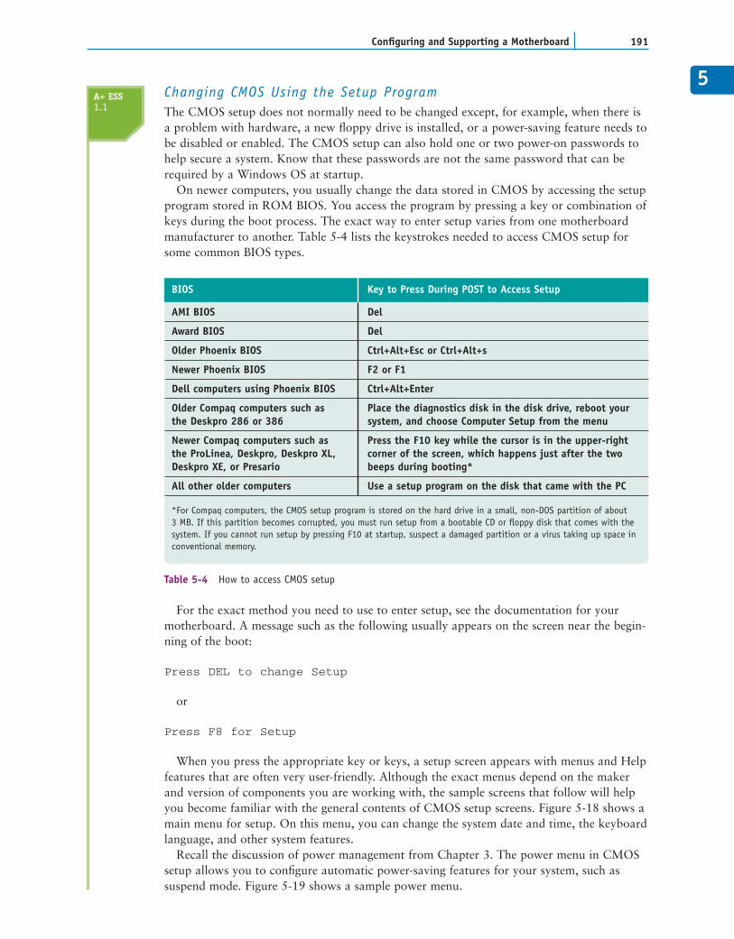
When you press the appropriate key or keys, a setup screen appears with menus and Helpfeatures that are often very user-friendly. Although the exact menus depend on the makerand version of components you are working with, the sample screens that follow will helpyou become familiar with the general contents of CMOS setup screens. Figure 5-18 shows amain menu for setup. On this menu, you can change the system date and time, the keyboardlanguage, and other system features.
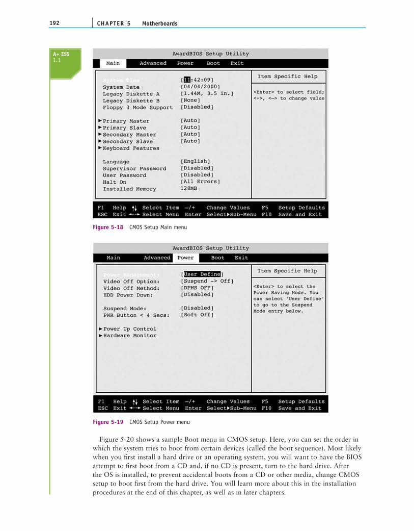
Recall the discussion of power management from Chapter 3. The power menu in CMOSsetup allows you to configure automatic power-saving features for your system, such assuspend mode. Figure 5-19 shows a sample power menu.
A+ ESS1.1
CHAPTER 5192 Motherboards
Figure 5-18 CMOS Setup Main menu
Figure 5-19 CMOS Setup Power menu
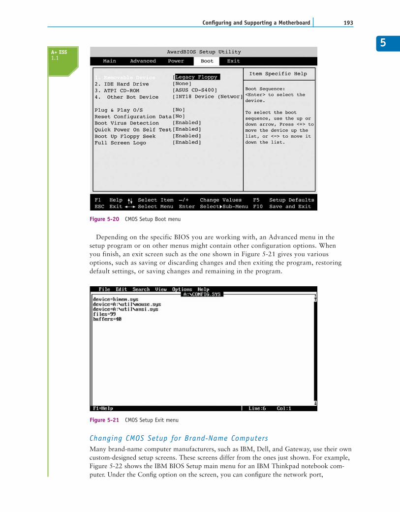
Figure 5-20 shows a sample Boot menu in CMOS setup. Here, you can set the order inwhich the system tries to boot from certain devices (called the boot sequence). Most likelywhen you first install a hard drive or an operating system, you will want to have the BIOSattempt to first boot from a CD and, if no CD is present, turn to the hard drive. Afterthe OS is installed, to prevent accidental boots from a CD or other media, change CMOSsetup to boot first from the hard drive. You will learn more about this in the installationprocedures at the end of this chapter, as well as in later chapters.
A+ ESS1.1
5
Depending on the specific BIOS you are working with, an Advanced menu in thesetup program or on other menus might contain other configuration options. Whenyou finish, an exit screen such as the one shown in Figure 5-21 gives you variousoptions, such as saving or discarding changes and then exiting the program, restoringdefault settings, or saving changes and remaining in the program.
193Configuring and Supporting a Motherboard
Figure 5-20 CMOS Setup Boot menu
Figure 5-21 CMOS Setup Exit menu
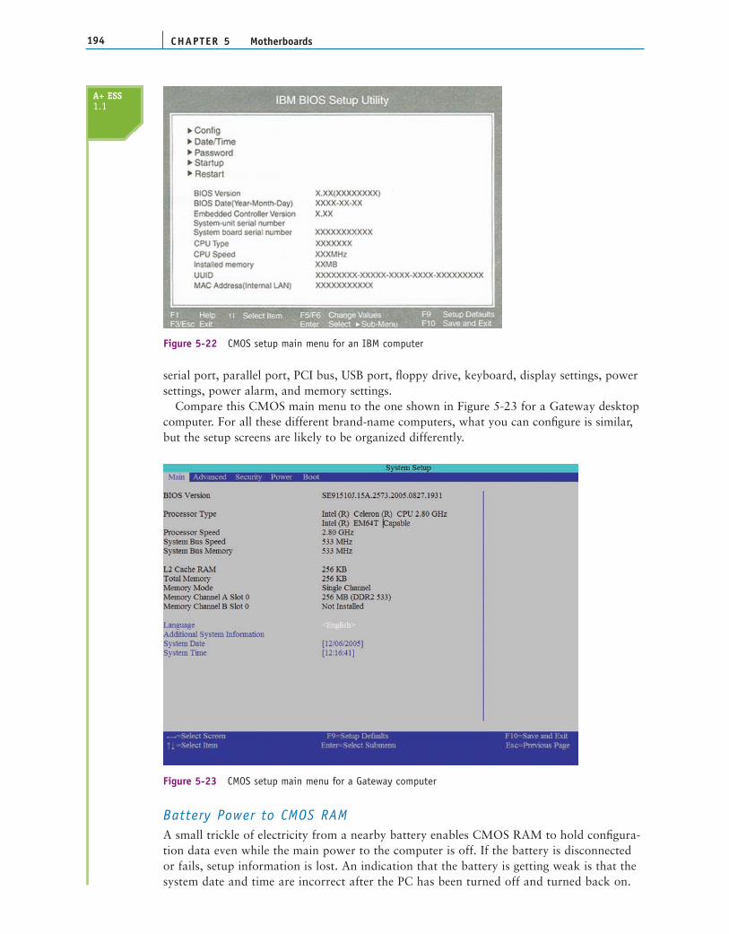
Changing CMOS Setup for Brand-Name ComputersMany brand-name computer manufacturers, such as IBM, Dell, and Gateway, use their owncustom-designed setup screens. These screens differ from the ones just shown. For example,Figure 5-22 shows the IBM BIOS Setup main menu for an IBM Thinkpad notebook com-puter. Under the Config option on the screen, you can configure the network port,
A+ ESS1.1
CHAPTER 5194 Motherboards
serial port, parallel port, PCI bus, USB port, floppy drive, keyboard, display settings, powersettings, power alarm, and memory settings.
Compare this CMOS main menu to the one shown in Figure 5-23 for a Gateway desktopcomputer. For all these different brand-name computers, what you can configure is similar,but the setup screens are likely to be organized differently.
Figure 5-22 CMOS setup main menu for an IBM computer
Figure 5-23 CMOS setup main menu for a Gateway computer
Battery Power to CMOS RAMA small trickle of electricity from a nearby battery enables CMOS RAM to hold configura-tion data even while the main power to the computer is off. If the battery is disconnectedor fails, setup information is lost. An indication that the battery is getting weak is that thesystem date and time are incorrect after the PC has been turned off and turned back on.
A+ ESS1.1
5
195Configuring and Supporting a Motherboard
Coin cell battery
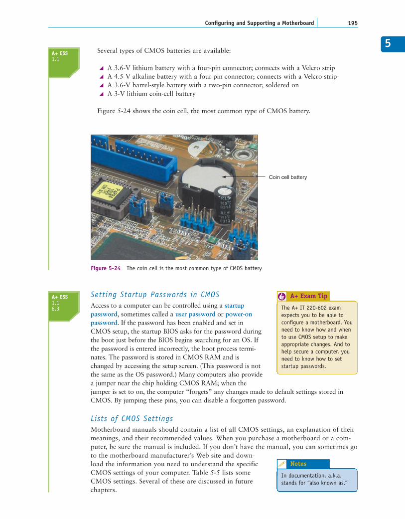
Figure 5-24 The coin cell is the most common type of CMOS battery
Setting Startup Passwords in CMOSAccess to a computer can be controlled using a startup password, sometimes called a user password or power-onpassword. If the password has been enabled and set inCMOS setup, the startup BIOS asks for the password duringthe boot just before the BIOS begins searching for an OS. Ifthe password is entered incorrectly, the boot process termi-nates. The password is stored in CMOS RAM and ischanged by accessing the setup screen. (This password is notthe same as the OS password.) Many computers also providea jumper near the chip holding CMOS RAM; when thejumper is set to on, the computer “forgets” any changes made to default settings stored inCMOS. By jumping these pins, you can disable a forgotten password.
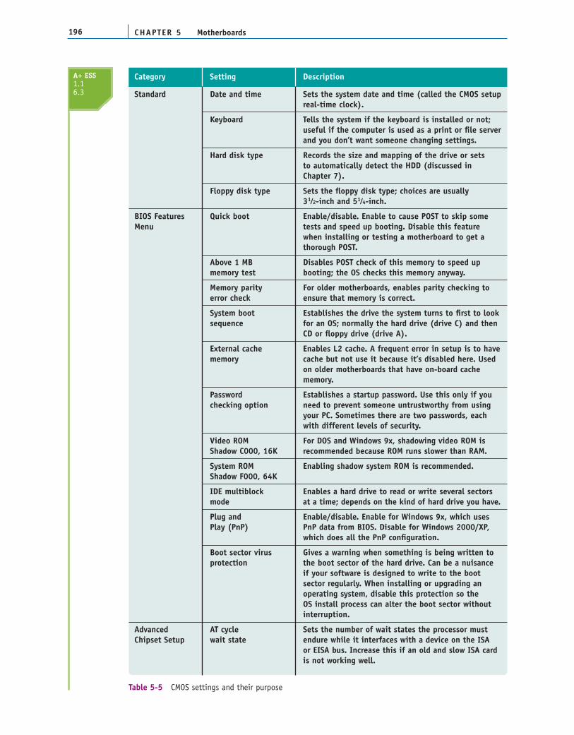
Lists of CMOS SettingsMotherboard manuals should contain a list of all CMOS settings, an explanation of theirmeanings, and their recommended values. When you purchase a motherboard or a com-puter, be sure the manual is included. If you don’t have the manual, you can sometimes goto the motherboard manufacturer’s Web site and down-load the information you need to understand the specificCMOS settings of your computer. Table 5-5 lists someCMOS settings. Several of these are discussed in futurechapters.
Several types of CMOS batteries are available:
A 3.6-V lithium battery with a four-pin connector; connects with a Velcro stripA 4.5-V alkaline battery with a four-pin connector; connects with a Velcro stripA 3.6-V barrel-style battery with a two-pin connector; soldered onA 3-V lithium coin-cell battery
Figure 5-24 shows the coin cell, the most common type of CMOS battery.
A+ ESS1.1
The A+ IT 220-602 examexpects you to be able toconfigure a motherboard. Youneed to know how and whento use CMOS setup to makeappropriate changes. And tohelp secure a computer, youneed to know how to setstartup passwords.
A+ Exam Tip6
In documentation, a.k.a.stands for “also known as.”
Notes
A+ ESS1.16.3
CHAPTER 5196 Motherboards
Standard Date and time Sets the system date and time (called the CMOS setupreal-time clock).
Keyboard Tells the system if the keyboard is installed or not; useful if the computer is used as a print or file serverand you don’t want someone changing settings.
Hard disk type Records the size and mapping of the drive or sets to automatically detect the HDD (discussed in Chapter 7).
Floppy disk type Sets the floppy disk type; choices are usually 31⁄2-inch and 51⁄4-inch.
BIOS Features Quick boot Enable/disable. Enable to cause POST to skip some Menu tests and speed up booting. Disable this feature
when installing or testing a motherboard to get a thorough POST.
Above 1 MB Disables POST check of this memory to speed upmemory test booting; the OS checks this memory anyway.
Memory parity For older motherboards, enables parity checking to error check ensure that memory is correct.
System boot Establishes the drive the system turns to first to looksequence for an OS; normally the hard drive (drive C) and then
CD or floppy drive (drive A).
External cache Enables L2 cache. A frequent error in setup is to havememory cache but not use it because it’s disabled here. Used
on older motherboards that have on-board cache memory.
Password Establishes a startup password. Use this only if you checking option need to prevent someone untrustworthy from using
your PC. Sometimes there are two passwords, each with different levels of security.
Video ROM For DOS and Windows 9x, shadowing video ROM is Shadow C000, 16K recommended because ROM runs slower than RAM.
System ROM Enabling shadow system ROM is recommended.Shadow F000, 64K
IDE multiblock Enables a hard drive to read or write several sectorsmode at a time; depends on the kind of hard drive you have.
Plug and Enable/disable. Enable for Windows 9x, which usesPlay (PnP) PnP data from BIOS. Disable for Windows 2000/XP,
which does all the PnP configuration.
Boot sector virus Gives a warning when something is being written toprotection the boot sector of the hard drive. Can be a nuisance
if your software is designed to write to the boot sector regularly. When installing or upgrading an operating system, disable this protection so the OS install process can alter the boot sector without interruption.
Advanced AT cycle Sets the number of wait states the processor must Chipset Setup wait state endure while it interfaces with a device on the ISA
or EISA bus. Increase this if an old and slow ISA card is not working well.
Category Setting Description
Table 5-5 CMOS settings and their purpose
A+ ESS1.16.3
5
197Configuring and Supporting a Motherboard
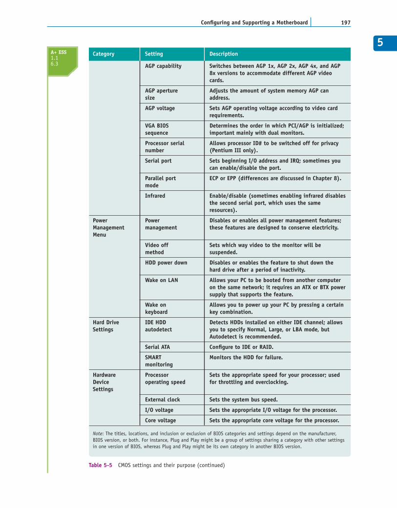
Table 5-5 CMOS settings and their purpose (continued)
AGP capability Switches between AGP 1x, AGP 2x, AGP 4x, and AGP 8x versions to accommodate different AGP video cards.
AGP aperture Adjusts the amount of system memory AGP can size address.
AGP voltage Sets AGP operating voltage according to video card requirements.
VGA BIOS Determines the order in which PCI/AGP is initialized;sequence important mainly with dual monitors.
Processor serial Allows processor ID# to be switched off for privacy number (Pentium III only).
Serial port Sets beginning I/O address and IRQ; sometimes you can enable/disable the port.
Parallel port ECP or EPP (differences are discussed in Chapter 8).mode
Infrared Enable/disable (sometimes enabling infrared disablesthe second serial port, which uses the same resources).
Power Power Disables or enables all power management features;Management management these features are designed to conserve electricity.Menu
Video off Sets which way video to the monitor will be method suspended.
HDD power down Disables or enables the feature to shut down the hard drive after a period of inactivity.
Wake on LAN Allows your PC to be booted from another computer on the same network; it requires an ATX or BTX powersupply that supports the feature.
Wake on Allows you to power up your PC by pressing a certainkeyboard key combination.
Hard Drive IDE HDD Detects HDDs installed on either IDE channel; allowsSettings autodetect you to specify Normal, Large, or LBA mode, but
Autodetect is recommended.
Serial ATA Configure to IDE or RAID.
SMART Monitors the HDD for failure.monitoring
Hardware Processor Sets the appropriate speed for your processor; used Device operating speed for throttling and overclocking.Settings
External clock Sets the system bus speed.
I/O voltage Sets the appropriate I/O voltage for the processor.
Core voltage Sets the appropriate core voltage for the processor.
Note: The titles, locations, and inclusion or exclusion of BIOS categories and settings depend on the manufacturer,BIOS version, or both. For instance, Plug and Play might be a group of settings sharing a category with other settingsin one version of BIOS, whereas Plug and Play might be its own category in another BIOS version.
Category Setting DescriptionA+ ESS1.16.3
PROTECTING DOCUMENTATION AND CONFIGURATION SETTINGSIf the battery goes bad or is disconnected, you can lose the settings saved in CMOS RAM.If you are using default settings, reboot with a good battery and instruct setup to restore thedefault settings. Setup has to autodetect the hard drive present, and you need to set the dateand time, but you can easily recover from the problem. However, if you have customizedsome CMOS settings, you need to restore them. The most reliable way to restore settings isto keep a written record of all the changes you make to CMOS.
If you are permanently responsible for a computer, you should consider keeping a writ-ten record of what you have done to maintain it. Use a small notebook or similar docu-ment to record CMOS settings that are not the default settings, hardware and softwareinstalled, network settings, and similar information. Suppose someone decides to tinkerwith a PC for which you are responsible, changes a jumper on the motherboard, and can-not remember which jumper she changed. The computer no longer works, and the docu-mentation for the board is now invaluable. Lost or misplaced documentation greatlycomplicates the otherwise simple job of reading the settings for each jumper and checkingthem on the board. Keep the documentation well labeled in a safe place. If you have sev-eral computers to maintain, you might consider a filing system for each computer.
CHAPTER 5198 Motherboards
Saving and Restoring CMOS SettingsUsing Third-Party Utility Software
If you lose CMOS settings, another way to restore them is to use a backup of the settings that youhave previously saved on a floppy disk. One third-party utility that allows you to save CMOS set-tings is Norton Utilities by Symantec (www.symantec.com). Sometimes the support CD that comeswith a motherboard has a utility on it to save CMOS settings to a floppy disk.
You can also download a shareware utility to record CMOS settings. One example follows, butknow that the files might change with new releases of the software.
1. Access the Internet and use a search engine to find a site offering Cmos.zip. Two currentlocations are: www.programmersheaven.com/zone24/cat31/4174.htm andwww.computerhope.com/downlod.htm.
2. Select and download Cmos.zip. You can then exit the Internet.
3. Unzip the compressed file and print the contents of the documentation file.
4. Double-click the Cmos.exe file you unzipped. The program shows the current contents ofCMOS memory in a DOS box.
5. Enter S (for Save) at the command line. Enter the drive letter of your floppy drive and a file-name to save the current CMOS settings to floppy disk. A sample path and filename mightbe A:MYCMOS.
6. Enter Q to quit the program.
APPLYING CONCEPTS
A+ ESS1.16.3
When you want to retrieve the contents of the file from thefloppy disk, run the Cmos.exe program again, and enter L (forLoad) at the command line, specifying the name of the fileyou saved on the floppy disk.
Notes
5Another method is to carefully tape a cardboard folder to the inside top or side of the com-puter case and safely tuck the hardware documentation there. This works well if you areresponsible for several computers spread over a wide area.
Regardless of the method you use, it’s important that you keep your written record up todate and stored with the hardware documentation in a safe place. Leaving it in the care ofusers who might not realize its value is probably not a good idea. The notebook and docu-mentation will be invaluable as you solve future problems with this PC.
FLASHING ROM BIOSRecall that ROM BIOS includes the CMOS setup program, the startup BIOS that managesthe startup process, and the system BIOS that manages basic I/O functions of the system.
199Configuring and Supporting a Motherboard
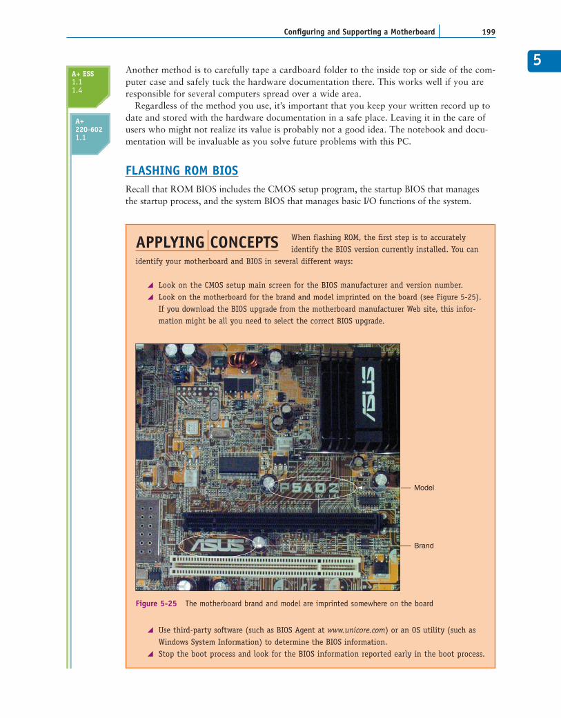
When flashing ROM, the first step is to accuratelyidentify the BIOS version currently installed. You can
identify your motherboard and BIOS in several different ways:
Look on the CMOS setup main screen for the BIOS manufacturer and version number.Look on the motherboard for the brand and model imprinted on the board (see Figure 5-25).If you download the BIOS upgrade from the motherboard manufacturer Web site, this infor-mation might be all you need to select the correct BIOS upgrade.
Use third-party software (such as BIOS Agent at www.unicore.com) or an OS utility (such asWindows System Information) to determine the BIOS information.Stop the boot process and look for the BIOS information reported early in the boot process.
APPLYING CONCEPTS
Model
Brand
Figure 5-25 The motherboard brand and model are imprinted somewhere on the board
A+ ESS1.11.4
A+220-6021.1
CHAPTER 5200 Motherboards
To stop the boot process early so you can read the BIOS information, first try the following:
1. Turn off the system power and then turn it back on.
2. While memory is counting on the screen, hold down the Pause/Break key to stop the startupprocess.
3. Look for the long string of numbers in the lower-left corner of your screen that identifies themotherboard.
4. Look for the BIOS manufacturer and version number somewhere near the top of the screen.
If the above list doesn’t work, try turning off the PC, unplugging the keyboard, and then turningon the PC. For older systems, the resulting keyboard error stops the boot process.
To flash ROM, carefully read the motherboard documentation, as different motherboards use differ-ent methods. If you can’t find the documentation, check the motherboard manufacturer’s Web site,and check the directions that came with the upgrade software. Generally, you perform these tasks:
1. Download the BIOS upgrade from the motherboard manufacturer Web site. If you can’t findan upgrade on this site, try the BIOS manufacturer Web site or a third-party site. Most oftenyou are instructed to save this upgrade to a bootable floppy disk.
2. Set a jumper on the motherboard, or change a setting in CMOS setup to tell BIOS to expectan upgrade.
3. Boot from the floppy disk and follow the menu options to upgrade BIOS. If the menu givesyou the option to save the old BIOS to disk, do so in case you need to revert to the old BIOS.
4. Set the jumper back to its original setting, reboot the system, and verify that all is working.
Makers of BIOS code are likely to change BIOS frequently because providing the upgrade on theInternet is so easy for them. You can get upgraded BIOS code from manufacturers’ Web sites ordisks, or from third-party BIOS resellers’ Web sites or disks. Generally, however, follow the principlethat “if it’s not broke, don’t fix it”; update your BIOS only if you’re having a problem with yourmotherboard or there’s a new BIOS feature you want to use.
A+ ESS1.11.4
A+220-6021.1
After flashing BIOS, if the motherboard gives problems, youneed to consider that the chipset drivers might also needupdating. To update the chipset drivers, go to the Web site ofthe motherboard manufacturer and download the chipsetdriver files for the OS you are using. Then follow the manufac-turer’s instructions to perform the update.
Notes
Be very careful that you upgrade BIOS with the correctupgrade and that you follow the manufacturer’s instructionscorrectly. Upgrading with the wrong file could make your sys-tem BIOS useless. If you’re not sure that you’re using the cor-rect upgrade, don’t guess. Check with the technical support foryour BIOS before moving forward. Before you call technicalsupport, have the information that identifies your BIOS andmotherboard available.
Caution
5
201Configuring and Supporting a Motherboard
All these programs are considered firmware and are stored on a chip on the motherboard,called the ROM BIOS chip or firmware chip. If a motherboard becomes unstable (such as whenthe system hangs at odd times), some functions are lost (such as a USB port stops working), oryou want to incorporate some new feature or component on the board (such as when youupgrade the processor), you might need to upgrade the programming stored on the ROM BIOSchip. The process of upgrading or refreshing the ROM BIOS chip is called flashing ROM.
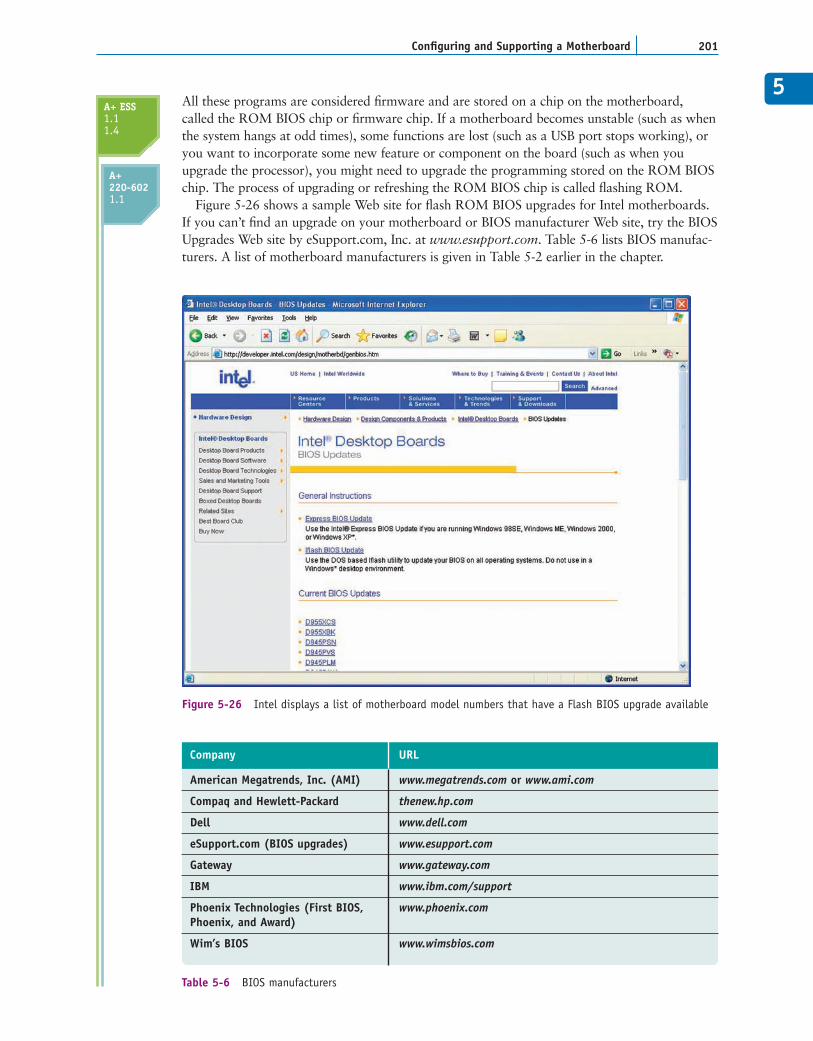
Figure 5-26 shows a sample Web site for flash ROM BIOS upgrades for Intel motherboards.If you can’t find an upgrade on your motherboard or BIOS manufacturer Web site, try the BIOSUpgrades Web site by eSupport.com, Inc. at www.esupport.com. Table 5-6 lists BIOS manufac-turers. A list of motherboard manufacturers is given in Table 5-2 earlier in the chapter.
Figure 5-26 Intel displays a list of motherboard model numbers that have a Flash BIOS upgrade available
American Megatrends, Inc. (AMI) www.megatrends.com or www.ami.com
Compaq and Hewlett-Packard thenew.hp.com
Dell www.dell.com
eSupport.com (BIOS upgrades) www.esupport.com
Gateway www.gateway.com
IBM www.ibm.com/support
Phoenix Technologies (First BIOS, www.phoenix.comPhoenix, and Award)
Wim’s BIOS www.wimsbios.com
Company URL
Table 5-6 BIOS manufacturers
A+ ESS1.11.4
A+220-6021.1
CHAPTER 5202 Motherboards
MOTHERBOARD DRIVERSA motherboard comes bundled with a CD that contains drivers for all the onboard com-ponents. Most likely Windows can use its own internal drivers for these components, butif you have trouble with an onboard component or want to use a feature that is notworking, use the motherboard CD to install the manufacturer drivers into Windows.Also, the motherboard manufacturer updates motherboard drivers from time to time. Foran unstable motherboard, you can try downloading and installing updated chipset driversand other drivers for onboard components.
The motherboard CD might also contain useful utilities such as a utility that you caninstall under Windows to monitor the CPU temperature and alert you if overheating occurs.
REPLACING A MOTHERBOARD
When you replace a motherboard, you pretty much have to disassemble an entire com-puter, install the new motherboard, and reassemble thesystem. The following list is meant to be a generaloverview of the process and is not meant to include thedetails of all possible installation scenarios, which canvary according to the components and OS you are using.The general process for replacing a motherboard is asfollows:
1. Verify that you have selected the right motherboard to install in the system. The newmotherboard should have the same form factor as the case, support the RAM mod-ules and processor you want to install on it, and have other internal and externalconnectors you need for your system.
2. Determine proper configuration settings for the motherboard. Especially importantare any jumpers, DIP switches, or CMOS settings specifically for the processor, andRAM speeds and timing. Read the motherboard manual from cover to cover. Youcan also check the manufacturer Web site for answers to any questions you mighthave.
3. Remove components so you can reach the old motherboard. Turn off the system anddisconnect all cables and cords. Open the case cover and remove all internal cablesand cords connected to the motherboard. Remove all expansion cards. To safelyremove the old motherboard, you might have to remove drives.
4. Set any jumpers or switches on the new motherboard. This is much easier to dobefore you put the board in the case.
5. Install the processor and processor cooler. The processor comes already installedon some motherboards, in which case you just need to install the cooler. Youmight need to add thermal compound. Also, if you are working with a heavycooling assembly, some manufacturers suggest you install the motherboard inthe case before installing the cooler. Follow motherboard and processor installa-tion instructions. Processor instructions take precedent over motherboardinstructions.
6. Install RAM into the appropriate slots on the motherboard.
7. Install the motherboard. Place the motherboard into the case and, using spacers orscrews, securely fasten the board to the case.
A+ ESS1.11.4
A+220-6021.1
The A+ IT 220-602 examexpects you to know howto select and install a motherboard.
A+ Exam Tip6
58. Attach cabling that goes from the case switches to the motherboard, and from the
power supply and drives to the motherboard. Pay attention to how cables are labeledand to any information in the documentation about where to attach them. Position andtie cables neatly together to make sure they don’t obstruct the fans and the air flow.
9. Install the video card on the motherboard. Usually this card goes into the AGP slotor PCI Express x16 slot.
10. Plug the computer into a power source, and attach the monitor and keyboard. Notethat you do not attach the mouse now, for the initial setup. Although the mouse gen-erally does not cause problems during setup, initially install only the things youabsolutely need.
11. Boot the system and enter CMOS setup. As you learned earlier in the chapter, youcan do this using several methods, depending on what type of system you have.
12. Make sure settings are set to the default. If the motherboard comes new from themanufacturer, it will already be at default settings. If you are salvaging a mother-board from another system, you might need to reset settings to the default. Generallya jumper or switch sets all CMOS settings to default settings. You will need to do thefollowing while you are in CMOS:
Check the time and date.Check the floppy drive type.Make sure abbreviated POST is disabled. While you’re installing a motherboard,you generally want it to do as many tests as possible. After you know the systemis working, you can choose to abbreviate POST.Set the boot order to the hard drive, then a CD, if you will be booting the OSfrom the hard drive.Make sure “autodetect hard disk” is set so that the system automatically looks fordrives.Leave everything else at their defaults unless you know that particular settingsshould be otherwise.Save and exit.
13. Observe POST and verify that no errors occur.
14. Check for conflicts with system resources. For Windows, use Device Manager toverify that the OS recognizes all devices and that no conflicts are reported.
15. Install the motherboard drives. If your motherboard comes with a CD that containssome motherboard drivers, install them now.
16. Install any other expansion cards and drives. Install each device and its drivers, onedevice at a time, rebooting and checking for conflicts after each installation.
17. Verify that everything isoperating properly, andmake any final OS andCMOS adjustments,such as power manage-ment settings.
Now let’s look at the detailsof installing the motherboardinto the computer case.
203Replacing a Motherboard
A+220-6021.1
Whenever you install or uninstall software or hardware, keep anotebook with details about the components you are workingon, configuration settings, manufacturer specifications, andother relevant information. This helps if you need to back-track later, and can also help you document and troubleshootyour computer system. Keep all hardware documentation forthis system together with the notebook in an envelope in asafe place.
Notes
PREPARING THE MOTHERBOARD TO GO INTO THE CASEBefore you begin preparing themotherboard, read the manualthat comes with it from begin-ning to end. The steps listed in
this section are general, and you will need to know informa-tion specific to your motherboard. Visually familiarize your-self with the configuration of the case and the motherboard.
SETTING THE JUMPERSThe first step in preparing the motherboard to go in the case
is to set the jumpers or DIP switches. When doing an installation, read the motherboard doc-umentation carefully, looking for explanations of how jumpers and DIP switches on theboard are used. This information differs from one motherboard to another. For older boards,a jumper group might control the system bus frequency and another group might control theCPU frequency multiplier. Set the jumpers and DIP switches according to the hardware youwill be installing.
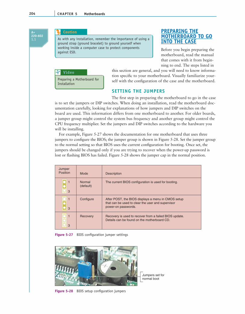
For example, Figure 5-27 shows the documentation for one motherboard that uses threejumpers to configure the BIOS; the jumper group is shown in Figure 5-28. Set the jumper groupto the normal setting so that BIOS uses the current configuration for booting. Once set, thejumpers should be changed only if you are trying to recover when the power-up password islost or flashing BIOS has failed. Figure 5-28 shows the jumper cap in the normal position.
CHAPTER 5204 Motherboards
JumperPosition Mode Description
Normal(default)
The current BIOS configuration is used for booting.
Configure After POST, the BIOS displays a menu in CMOS setupthat can be used to clear the user and supervisorpower-on passwords.
Recovery is used to recover from a failed BIOS update.Details can be found on the motherboard CD.
Recovery
1
3
1
3
1
3
Figure 5-27 BIOS configuration jumper settings
Jumpers set fornormal boot
Figure 5-28 BIOS setup configuration jumpers
A+220-6021.1
Preparing a Motherboard forInstallation
Video 8
As with any installation, remember the importance of using aground strap (ground bracelet) to ground yourself whenworking inside a computer case to protect componentsagainst ESD.
Caution
5
205Replacing a Motherboard
ADDING THE PROCESSOR, FAN, HEAT SINK, AND MEMORY MODULESNow that you have set the jumpers on the motherboard, you are ready to add the
processor itself. Check out Chapter 4 for information onhow to install a processor and cooler assembly. Youthen need to install RAM in the memory slots. Chapter 6covers how to buy and install RAM for a specificmotherboard.
INSTALLING THE MOTHERBOARD IN THE CASEHere are the general steps for installing the motherboard in the case:
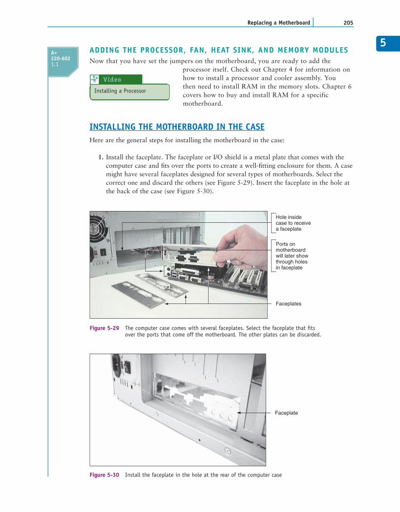
1. Install the faceplate. The faceplate or I/O shield is a metal plate that comes with thecomputer case and fits over the ports to create a well-fitting enclosure for them. A casemight have several faceplates designed for several types of motherboards. Select thecorrect one and discard the others (see Figure 5-29). Insert the faceplate in the hole atthe back of the case (see Figure 5-30).
Faceplates
Hole insidecase to receivea faceplate
Ports onmotherboardwill later showthrough holesin faceplate
Figure 5-29 The computer case comes with several faceplates. Select the faceplate that fits over the ports that come off the motherboard. The other plates can be discarded.
Faceplate
Figure 5-30 Install the faceplate in the hole at the rear of the computer case
A+220-6021.1
Installing a Processor
Video 8
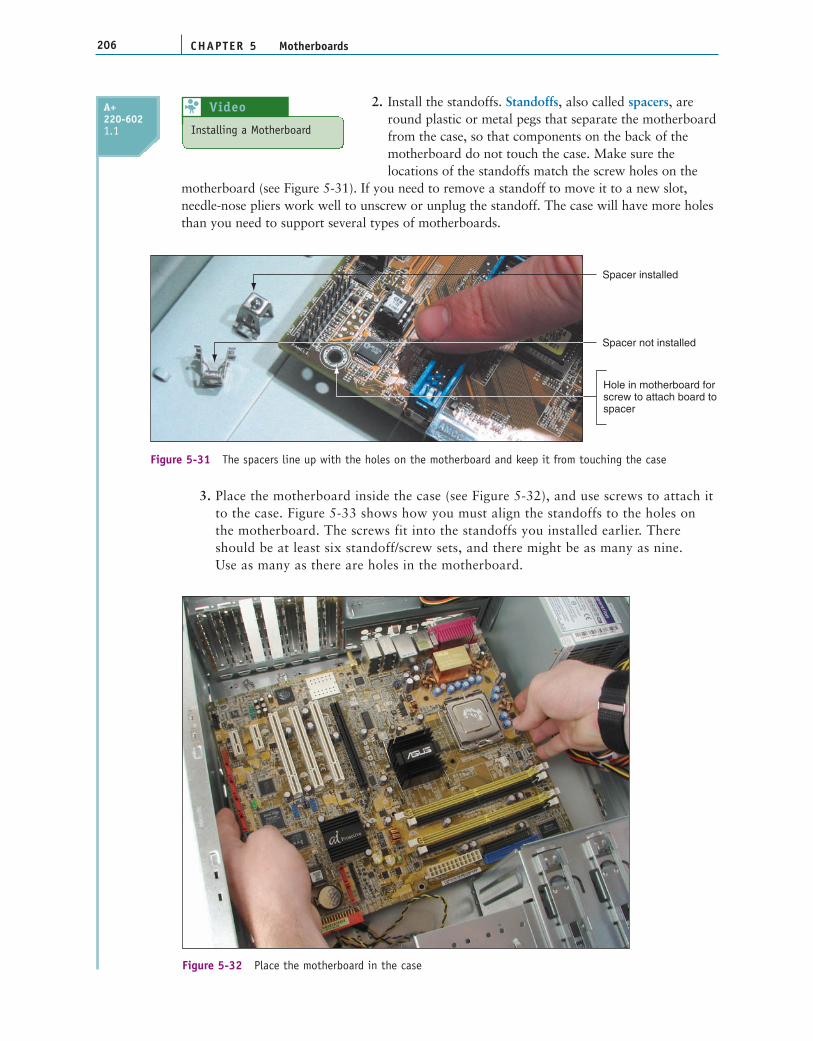
2. Install the standoffs. Standoffs, also called spacers, are round plastic or metal pegs that separate the motherboard from the case, so that components on the back of the motherboard do not touch the case. Make sure the locations of the standoffs match the screw holes on the
motherboard (see Figure 5-31). If you need to remove a standoff to move it to a new slot,needle-nose pliers work well to unscrew or unplug the standoff. The case will have more holesthan you need to support several types of motherboards.
CHAPTER 5206 Motherboards
3. Place the motherboard inside the case (see Figure 5-32), and use screws to attach itto the case. Figure 5-33 shows how you must align the standoffs to the holes onthe motherboard. The screws fit into the standoffs you installed earlier. Thereshould be at least six standoff/screw sets, and there might be as many as nine.Use as many as there are holes in the motherboard.
Spacer not installed
Hole in motherboard forscrew to attach board tospacer
Spacer installed
Figure 5-31 The spacers line up with the holes on the motherboard and keep it from touching the case
Figure 5-32 Place the motherboard in the case
Installing a Motherboard
Video 8A+220-6021.1
5
207Replacing a Motherboard
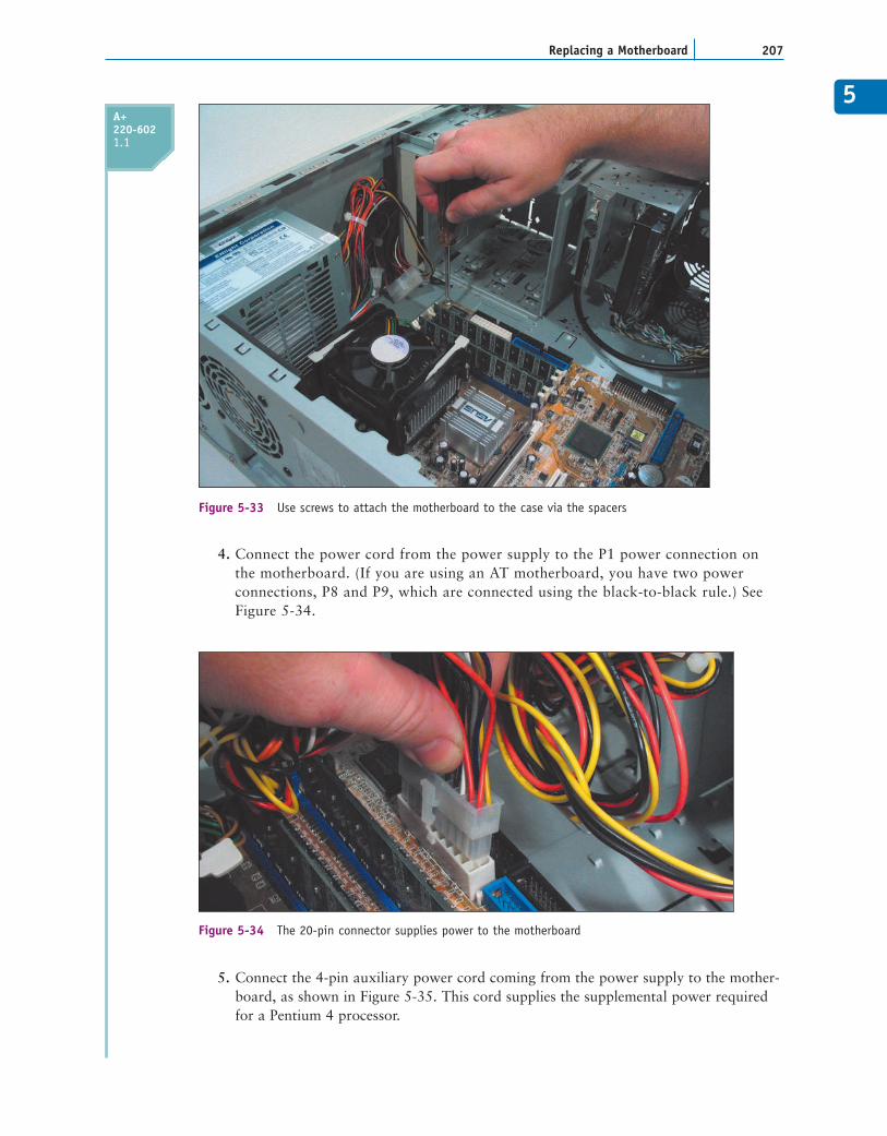
Figure 5-34 The 20-pin connector supplies power to the motherboard
Figure 5-33 Use screws to attach the motherboard to the case via the spacers
4. Connect the power cord from the power supply to the P1 power connection onthe motherboard. (If you are using an AT motherboard, you have two powerconnections, P8 and P9, which are connected using the black-to-black rule.) SeeFigure 5-34.
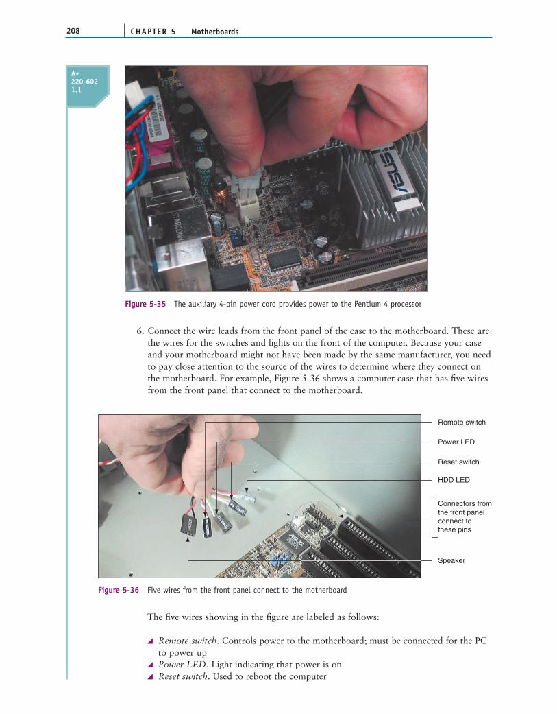
5. Connect the 4-pin auxiliary power cord coming from the power supply to the mother-board, as shown in Figure 5-35. This cord supplies the supplemental power requiredfor a Pentium 4 processor.
A+220-6021.1
CHAPTER 5208 Motherboards
Remote switch
Connectors from the front panelconnect tothese pins
Power LED
Reset switch
HDD LED
Speaker
Figure 5-36 Five wires from the front panel connect to the motherboard
6. Connect the wire leads from the front panel of the case to the motherboard. These arethe wires for the switches and lights on the front of the computer. Because your caseand your motherboard might not have been made by the same manufacturer, you needto pay close attention to the source of the wires to determine where they connect onthe motherboard. For example, Figure 5-36 shows a computer case that has five wiresfrom the front panel that connect to the motherboard.
Figure 5-35 The auxiliary 4-pin power cord provides power to the Pentium 4 processor
A+220-6021.1
The five wires showing in the figure are labeled as follows:
Remote switch. Controls power to the motherboard; must be connected for the PCto power upPower LED. Light indicating that power is onReset switch. Used to reboot the computer
5
209Replacing a Motherboard
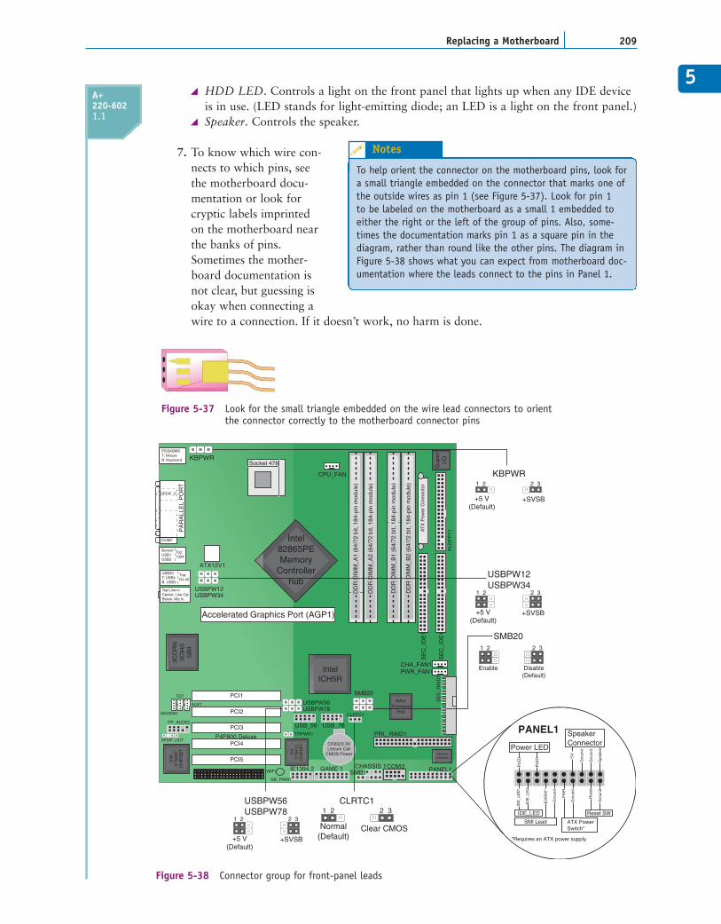
Figure 5-37 Look for the small triangle embedded on the wire lead connectors to orient the connector correctly to the motherboard connector pins
CHASSIS 1 SMB1
GAME 1
VIA
VT
6307
CH
IPS
ET
VIA
VT
6410
CH
IPS
ET
4Mbi tFirmware
Hub
P4P800 Deluxe
3CO
RN
3C94
0G
Bit
CR2023 3VLithium Cell
CMOS Power
COM2
CLRTC1
USB_78USB_56PRI_ RAID1
PANEL1
SpeechControlle
TRPWR1
SMB20
IE1394.2
SB_PWR1
WIFI
PCI5
PCI4
PCI3
PCI2
PCI1USBPW56USBPW78
IntelICH5R
SPDIF_OUT
FP_AUDIO
CD1
MODEM1
AUX1
Socket 478
CPU_FAN
DD
R D
IMM
_A1
(64/
72 b
it, 1
84-p
in m
odul
e)
DD
R D
IMM
_A2
(64/
72 b
it, 1
84-p
in m
odul
e)
DD
R D
IMM
_B1
(64/
72 b
it, 1
84-p
in m
odul
e)
DD
R D
IMM
_B2
(64/
72 b
it, 1
84-p
in m
odul
e)
Sup
erI/O
AT
X P
ower
Con
nect
or
FLO
PP
Y1
SE
C_I
DE
1
SE
C_I
DE
1
CHA_FAN1PWR_FAN1
SE
C_R
AID
1
USBPW12USBPW34
KBPWR
Top:Line inCenter: Line OutBelow: Mic In
USB2.0T: USB4B: USB3
Top:RJ-45
Bottom:USB1USB2
Top:1394
COM1
SPDIF_O
PA
RA
LLE
L P
OR
T
PS/2KBMST: MouseB: Keyboard KBPWR
ATX12V1
Intel82865PEMemory
Controllerhub
Accelerated Graphics Port (AGP1)
USBPW12USBPW34
SMB20
+5 V(Default)
+SVSB
1 2 2 3
2 31 2
Disable(Default)
Enable
USBPW56USBPW78
CLRTC1
Normal(Default)
Clear CMOS
2 31 2
+5 V(Default)
+SVSB
1 2 2 3
+5 V(Default)
+SVSB
1 2 2 3
PANEL1
PLE
D
PLE
D
IDE
_LE
D*
IDE
_LE
D
Ext
SM
I*
Gro
und
PW
R
Gro
und
Res
et
Gro
und
Gro
und
Spe
aker
Gro
und
*5V
Power LED
*Requires an ATX power supply.
SMI Lead
IDE_LED Reset SW
ATX PowerSwitch*
SpeakerConnector
Figure 5-38 Connector group for front-panel leads
A+220-6021.1
HDD LED. Controls a light on the front panel that lights up when any IDE deviceis in use. (LED stands for light-emitting diode; an LED is a light on the front panel.)Speaker. Controls the speaker.
7. To know which wire con-nects to which pins, seethe motherboard docu-mentation or look forcryptic labels imprintedon the motherboard nearthe banks of pins.Sometimes the mother-board documentation isnot clear, but guessing isokay when connecting awire to a connection. If it doesn’t work, no harm is done.
To help orient the connector on the motherboard pins, look fora small triangle embedded on the connector that marks one ofthe outside wires as pin 1 (see Figure 5-37). Look for pin 1to be labeled on the motherboard as a small 1 embedded toeither the right or the left of the group of pins. Also, some-times the documentation marks pin 1 as a square pin in thediagram, rather than round like the other pins. The diagram inFigure 5-38 shows what you can expect from motherboard doc-umentation where the leads connect to the pins in Panel 1.
Notes
CHAPTER 5210 Motherboards
COMPLETING THE INSTALLATIONAfter you install the motherboard and connect all cables and cords, next you install thevideo card and plug in the keyboard and monitor. You are now ready to turn on the systemand observe POST occurs with no errors. After the Windows desktop loads, insert the CDthat came bundled with the motherboard and execute any setup program on the CD. Followthe steps onscreen to install any drivers, which might include drivers for onboard devicesand ports such as video, network, audio, USB, RAID, or the chipset.
Look back at the general list of steps to replace a motherboard at the beginning of thissection for the list of things to check and do to complete the installation and return the sys-tem to good working order.
TROUBLESHOOTING THE MOTHERBOARD AND PROCESSOR
Items that can be exchanged without returning the motherboard to the factory are calledfield replaceable units (FRUs). On older AT motherboards, these FRU components were theprocessor, RAM, RAM cache, ROM BIOS chip, and CMOS battery. On newer mother-boards, FRU components are the processor, RAM, and CMOS battery. Also, the mother-board itself is an FRU. As you troubleshoot the motherboard and discover that some
component is not working, such as a network port, youmight be able to disable that component in CMOS setupand install a card to take its place.
When troubleshooting the motherboard, use whateverclues POST can give you. Recall that, before it checks video,POST reports any error messages as beep codes. When a PCboots, one beep indicates that all is well after POST.
Two USB ports onthe front of the case
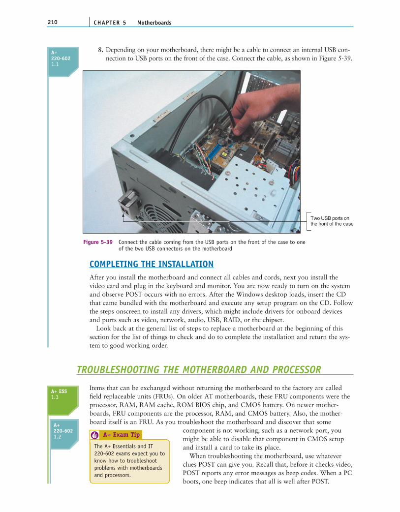
Figure 5-39 Connect the cable coming from the USB ports on the front of the case to one of the two USB connectors on the motherboard
The A+ Essentials and IT220-602 exams expect you toknow how to troubleshootproblems with motherboardsand processors.
A+ Exam Tip6
A+220-6021.1
A+220-6021.2
A+ ESS1.3
8. Depending on your motherboard, there might be a cable to connect an internal USB con-nection to USB ports on the front of the case. Connect the cable, as shown in Figure 5-39.
5
211Troubleshooting the Motherboard and Processor
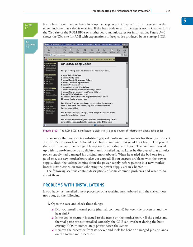
Figure 5-40 The ROM BIOS manufacturer’s Web site is a good source of information about beep codes
If you hear more than one beep, look up the beep code in Chapter 2. Error messages on thescreen indicate that video is working. If the beep code or error message is not in Chapter 2, trythe Web site of the ROM BIOS or motherboard manufacturer for information. Figure 5-40shows the Web site for AMI with explanations of beep codes produced by its startup BIOS.
Remember that you can try substituting good hardware components for those you suspectare bad. Be cautious here. A friend once had a computer that would not boot. He replacedthe hard drive, with no change. He replaced the motherboard next. The computer bootedup with no problem; he was delighted, until it failed again. Later he discovered that a faultypower supply had damaged his original motherboard. When he traded the bad one for agood one, the new motherboard also got zapped! If you suspect problems with the powersupply, check the voltage coming from the power supply before putting in a new mother-board! (Instructions on troubleshooting the power supply are in Chapter 3.)
The following sections contain descriptions of some common problems and what to doabout them.
PROBLEMS WITH INSTALLATIONSIf you have just installed a new processor on a working motherboard and the system doesnot boot, do the following:
1. Open the case and check these things:
Did you install thermal paste (thermal compound) between the processor and theheat sink?Is the cooler securely fastened to the frame on the motherboard? If the cooler andthermal paste are not installed correctly, the CPU can overheat during the boot,causing BIOS to immediately power down the system.Remove the processor from its socket and look for bent or damaged pins or landson the socket and processor.
A+ ESS1.3
A+220-6021.2
CHAPTER 5212 Motherboards
2. Reinstall the processor and try the boot again.
3. Reinstall the old processor, flash BIOS, and then try the new processor again.
If you have just installed a new motherboard that is not working, check the following:
Have you installed the front cover on the case? Sometimes a system refuses to powerup until this cover is in place.Is there a power switch on the back of the case that is not turned on?Study the documentation and verify all connections are correct. Most likely this isthe problem. Remember the Power Switch lead from the front of the case must be con-nected to the panel on the motherboard.Verify the processor, thermal compound, and cooler are all installed correctly.Remove RAM and reinstall the modules.Verify a standoff that is not being used by the motherboard is not under the mother-board and causing a short.If the system can boot into Windows, install all motherboard drivers on the CD thatcame bundled with the board.Check the motherboard Web site for other things you can check or try.
PROBLEMS WITH THE MOTHERBOARD AND PROCESSORSymptoms that a motherboard or processor is failing can appear as:
The system begins to boot but then powers down.An error message displays during the boot. Investigate this message.The system becomes unstable, hangs, or freezes at odd times.Intermittent Windows or hard drive errors occur.Components on the motherboard or devices connected to it don’t work.
The motherboard might have come bundled with a support CD. Look on it for drivers ofboard components that are not working. For example, if the USB ports are not working, tryupdating the USB drivers with those stored on the support CD. Load the CD and followdirections onscreen.
If this doesn’t resolve the problem, try the following:
A power-saving feature might be the source of the problem. Ask yourself, “Is the sys-tem in a doze or sleep mode?” Many “green,” or environmentally friendly, systemscan be programmed through CMOS to suspend the monitor or even the drive if thekeyboard or processor has been inactive for a few minutes. Pressing any key usuallycauses operations to resume exactly where the user left off.If the fan is running, reseat or replace the processor, BIOS, or RAM. Try installing aDIMM in a different slot. A POST code diagnostic card is a great help at this point.These cards are discussed in Chapter 2.Sometimes a dead computer can be fixed by simply disassembling it and reseatingcables, adapter cards, socketed chips, and SIMMs, DIMMs, or RIMMs. Bad connec-tions and corrosion are common problems.Check jumpers, DIP switches, and CMOS settings.Look for physical damage on the motherboard. Look for frayed traces on the bottomof the board or brown or burnt capacitors on the board.Check CMOS for a temperature reading that indicates overheating.
A+ ESS1.3
A+220-6021.2
5
213Troubleshooting the Motherboard and Processor
Flash BIOS.A dead or dying battery may cause problems. Sometimes, after a long holiday, a weakbattery causes the CMOS to forget its configuration.Try using the CD that came with the motherboard, which most likely has diagnostictests on it that might identify the problem with the motherboard.Reduce the system to essentials. Remove any unnecessary hardware, such as expansioncards, and then try to boot again.Exchange the processor.If an onboard component isn’t working but the motherboard is stable, go into CMOSsetup and disable the component. Then install a replacement component using a portor expansion slot.Exchange the motherboard, but before you do, measure the voltage output of thepower supply or simply replace it, in case it is producing too much power and hasdamaged the board.
Jessica complained to Wally, her PC support technician,that Windows was occasionally giving errors, data
would get corrupted, or an application would not work as it should. At first Wally suspected Jessicamight need a little more training in how to open and close an application or save a file, but he dis-covered user error was not the problem. He tried reinstalling the application software Jessica most
often used, and even reinstalled Windows, but the problemspersisted.
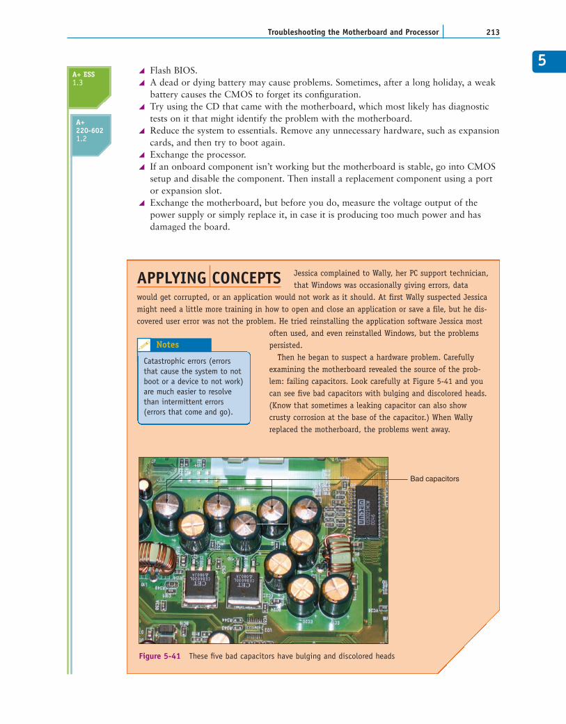
Then he began to suspect a hardware problem. Carefullyexamining the motherboard revealed the source of the prob-lem: failing capacitors. Look carefully at Figure 5-41 and youcan see five bad capacitors with bulging and discolored heads.(Know that sometimes a leaking capacitor can also showcrusty corrosion at the base of the capacitor.) When Wallyreplaced the motherboard, the problems went away.
APPLYING CONCEPTS
Catastrophic errors (errorsthat cause the system to notboot or a device to not work)are much easier to resolvethan intermittent errors(errors that come and go).
Notes
Bad capacitors
Figure 5-41 These five bad capacitors have bulging and discolored heads
A+ ESS1.3
A+220-6021.2
CHAPTER 5214 Motherboards
>> KEY TERMS
audio/modem riser (AMR)communication and networking
riser (CNR)dual inline package (DIP) switchIndustry Standard Architecture
(ISA) slot
jumperon-board portspower-on passwordriser cardspacersstandoffs
startup passworduser passwordwait state
For explanations of key terms, see the Glossary near the end of the book.
>> CHAPTER SUMMARY
The motherboard is the most complicated of all components inside the computer. It con-tains the processor and accompanying chipset, real-time clock, ROM BIOS, CMOSconfiguration chip, RAM, RAM cache, system bus, expansion slots, jumpers, ports, andpower supply connections. The motherboard you select determines both the capabilitiesand limitations of your system.
Some components can be built in to the motherboard, in which case they are called on-board components. Other components can be attached to the system in some otherway, such as on an expansion card.
A bus is a path on the motherboard that carries electrical power, control signals, memoryaddresses, and data to different components on the board.
A bus can be 16, 32, 64, or more bits wide. The first ISA bus had an 8-bit data path.The second ISA slot had a 16-bit data path.
Some outdated buses are the 16-bit ISA, 32-bit MCA and EISA buses, and VESA bus.Current buses are the PCI bus, AGP bus, and PCI Express. A local bus runs in sync withthe system clock and is designed to allow fast devices quicker and more direct access tothe processor than other buses. In addition, if the bus connects to the North Bridge ofthe chipset, it has more direct and faster access to the processor than if it attaches to theslower South Bridge. A bus slot used for a PCI Express x16 or AGP video card connectsto the North Bridge.
The most common method of configuring components on a motherboard is CMOSsetup. Some motherboards also use jumpers or DIP switches to contain configurationsettings.
Jumpers on older motherboards can be used to set the motherboard speed and the proces-sor frequency multiplier, which determines the processor speed. For newer boards, thesesettings are autodetected without the use of jumpers.
ROM chips contain the programming code to manage POST and the system BIOSand to change CMOS settings. The setup or CMOS chip holds configuration information.
Sometimes ROM BIOS programming stored on the firmware chip needs updating orrefreshing. This process is called flashing BIOS.
When installing a motherboard, first study the motherboard and set jumpers and DIPswitches on the board. Sometimes the processor and cooler are best installed beforeinstalling the motherboard in the case. When the cooling assembly is heavy and bulky, itis best to install it after the motherboard is securely seated in the case.
5
215Thinking Critically
1. What are three main categories of form factors used for motherboards?
2. How many power cords connect to a Baby AT motherboard?
3. On the Enhanced ATX motherboard that supports PCI Express, how many pins does theP1 power connector have?
4. What are the names of the two power connectors used on the AT motherboard form factors?
5. What is the name of the one power connector on the ATX motherboard form factor?
6. How many pins does the regular ATX power connector to the motherboard have? Howmany pins does the Enhanced ATX power connector to the motherboard have?
7. What are the three versions of the BTX form factor for motherboards?
8. Name 10 components that are contained on a motherboard.
9. What are two data bus widths used by the conventional PCI bus?
10. When people speak of bus size, to what are they specifically referring?
11. What are the four speeds of the most popular motherboards currently available on themarket that support Intel processors?
12. Name the three most popular manufacturers of the system BIOS programs.
13. Which is faster, a PCI Express x16 bus or the latest AGP bus?
14. What is one reason to flash BIOS?
15. What is the easiest way to obtain the latest software to upgrade BIOS?
16. When examining a PCI expansion card, how can you tell what voltage(s) the card can use?
17. What are the four categories of cargo that are carried over a bus?
18. What bus is expected to replace AGP to support the video card in a system?
19. What is the name of the BIOS program that edits the values in CMOS RAM?
20. Describe how you can access the CMOS setup program.
>> REVIEWING THE BASICS
>> THINKING CRITICALLY
1. Why does a motherboard sometimes support more than one system bus speed?
2. Why don’t all buses on a motherboard operate at the same speed?
3. When you turn off a computer at night, it loses the date, and you must reenter it eachmorning. What is the problem and how do you solve it?
4. Why do you think the trend is to store configuration information on a motherboard inCMOS setup rather than by using jumpers or switches?
5. When troubleshooting a motherboard, you discover the modem port no longer works.What is the best and least expensive solution to this problem?
a. Replace the motherboard.
b. Disable the modem port and install a modem card in an expansion slot.
CHAPTER 5216 Motherboards
>> HANDS-ON PROJECTS
PROJECT 5-1: Recognizing Motherboard Components
Obtain the manual for a motherboard. If you don’t have a printed manual, use the Internetto search for a motherboard Web site, then download and print a manual. For example, tryASUS at www.asus.com or Abit at www.abit.com.tw. Look for a diagram of the mother-board components. Identify as many components from your diagram as you can. Copy thediagram and circle the components you recognize.
PROJECT 5-2: Examining the Motherboard in Detail
1. Look at the back of your computer. Without opening the case, list the ports that youbelieve come directly from the motherboard.
2. Remove the cover of the case, which you learned to do in Chapter 2. List the differentcircuit boards in the expansion slots. Was your guess correct about which ports comefrom the motherboard?
3. To expose the motherboard so you can identify its parts, remove all the expansionboards, as discussed in Chapter 2.
4. Draw a diagram of the motherboard and label these parts:
Processor (include the prominent label on the processor housing)RAM (SIMMs, DIMMs, or RIMMs)CMOS batteryExpansion slots (identify the slots as PCI, PCIe, AGP, ISA, EISA, MCA)Each port coming directly from the motherboardPower supply connectionsHard drive data connectors and floppy drive connector
5. Draw a rectangle on the diagram to represent each bank of jumpers on the board.
6. You can complete the following activity only if you have the documentation for themotherboard: Locate the jumper on the board that erases CMOS and/or the startup pass-word, and label this jumper on your diagram. It is often found near the battery. Someboards might have more than one, and some have none.
7. Reassemble the computer, as you learned to do in Chapter 2.
c. Use an external modem that connects to the serial or USB port.
d. Return the motherboard to the factory for repair.
6. A computer freezes at odd times. At first you suspect the power supply or overheating, butyou have eliminated overheating and replaced the power supply without solving the prob-lem. What do you do next?
a. Replace the processor.
b. Replace the motherboard.
c. Reinstall Windows.
d. Replace the memory modules.
e. Flash BIOS.
5
217Hands-On Projects
PROJECT 5-3: Saving and Restoring CMOS Settings
Save your CMOS settings on a disk, using either Norton Utilities or the shareware programcontained in Cmos.zip that you can download from the Web. This chapter includes instructionsin the section “Saving and Restoring CMOS Settings Using Third-Party Utility Software.”
PROJECT 5-4: Inserting and Removing Motherboards
Using old or defective expansion cards and motherboards, practice inserting and removingexpansion cards and motherboards.
PROJECT 5-5: Understanding Hardware Documentation
Obtain the manual for the motherboard for your PC. (If you cannot find the manual, trydownloading it from the motherboard manufacturer’s Web site.) List at least three functionsof jumpers on the board as well as the corresponding jumper settings. List the processorsthat the board supports.
PROJECT 5-6: Using the Internet for Research
In this project, you will learn how useful the Internet can be for a PC support technician.
1. Using your own or a lab computer, pretend that the motherboard manual is not avail-able and you need to know the settings for the jumpers on the motherboard. Identifythe manufacturer and model of the motherboard by looking for the manufacturername and model number stamped on the board. Research the Web site for that manu-facturer. Print the jumper settings for the motherboard from the Web site.
2. Research the Web site for your motherboard and print the instructions for flashing BIOS.
3. Research the Abit Web site (www.abit.com.tw) and print a photograph of a mother-board that has a riser slot. Also print the photograph of the riser card that fits thisslot. What is the function of the riser card?
PROJECT 5-7: Exchanging the CMOS Battery
To practice the steps for exchanging a CMOS battery, do the following:
1. Locate the CMOS battery on your computer’s motherboard. What is written on top ofthe battery?
2. Using the Internet, find a replacement for this battery. Print the Web page showing thebattery. How much does the new battery cost?
3. Enter CMOS setup on your computer. Write down any CMOS settings that are notdefault settings. You’ll need these settings later when you reinstall the battery.
4. Turn off the PC, remove the battery, and boot the PC. What error messages appear?What is the system date and time?
5. Power down the PC, replace the battery, and boot the PC. Return CMOS settings to theway you found them.
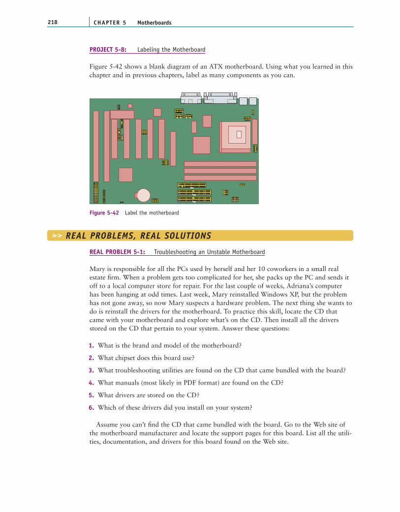
REAL PROBLEM 5-1: Troubleshooting an Unstable Motherboard
Mary is responsible for all the PCs used by herself and her 10 coworkers in a small realestate firm. When a problem gets too complicated for her, she packs up the PC and sends itoff to a local computer store for repair. For the last couple of weeks, Adriana’s computerhas been hanging at odd times. Last week, Mary reinstalled Windows XP, but the problemhas not gone away, so now Mary suspects a hardware problem. The next thing she wants todo is reinstall the drivers for the motherboard. To practice this skill, locate the CD thatcame with your motherboard and explore what’s on the CD. Then install all the driversstored on the CD that pertain to your system. Answer these questions:
1. What is the brand and model of the motherboard?
2. What chipset does this board use?
3. What troubleshooting utilities are found on the CD that came bundled with the board?
4. What manuals (most likely in PDF format) are found on the CD?
5. What drivers are stored on the CD?
6. Which of these drivers did you install on your system?
Assume you can’t find the CD that came bundled with the board. Go to the Web site ofthe motherboard manufacturer and locate the support pages for this board. List all the utili-ties, documentation, and drivers for this board found on the Web site.
CHAPTER 5218 Motherboards
>> REAL PROBLEMS, REAL SOLUTIONS
Figure 5-42 Label the motherboard
PROJECT 5-8: Labeling the Motherboard
Figure 5-42 shows a blank diagram of an ATX motherboard. Using what you learned in thischapter and in previous chapters, label as many components as you can.

5REAL PROBLEM 5-2: Selecting a Replacement Motherboard
When a motherboard fails, you can select and buy a new board to replace it. Suppose themotherboard used in Real Problem 5-1 has failed and you want to buy a replacement andkeep your repair costs to a minimum. Try to find a replacement motherboard on the Internetthat can use the same case, power supply, processor, memory, and expansion cards as yourcurrent system. If you cannot find a good match, what other components might have to bereplaced (for example, the processor or memory)? What is the total cost of the repair? PrintWeb pages showing what you need to purchase.
219Real Problems, Real Solutions
